US10723045B2 - Vehicular lamp and vehicle comprising same - Google Patents
Vehicular lamp and vehicle comprising same Download PDFInfo
- Publication number
- US10723045B2 US10723045B2 US16/310,695 US201716310695A US10723045B2 US 10723045 B2 US10723045 B2 US 10723045B2 US 201716310695 A US201716310695 A US 201716310695A US 10723045 B2 US10723045 B2 US 10723045B2
- Authority
- US
- United States
- Prior art keywords
- film
- optical film
- vehicular lamp
- unit optical
- patterns
- Prior art date
- Legal status (The legal status is an assumption and is not a legal conclusion. Google has not performed a legal analysis and makes no representation as to the accuracy of the status listed.)
- Active
Links
- 238000002372 labelling Methods 0.000 claims abstract description 5
- 239000012788 optical film Substances 0.000 claims description 176
- 239000010408 film Substances 0.000 claims description 135
- 238000000926 separation method Methods 0.000 claims description 33
- 239000010410 layer Substances 0.000 claims description 17
- 230000003647 oxidation Effects 0.000 claims description 16
- 238000007254 oxidation reaction Methods 0.000 claims description 16
- 230000002265 prevention Effects 0.000 claims description 12
- 239000012790 adhesive layer Substances 0.000 claims description 9
- 238000002347 injection Methods 0.000 claims description 5
- 239000007924 injection Substances 0.000 claims description 5
- 229910000976 Electrical steel Inorganic materials 0.000 claims description 3
- XAGFODPZIPBFFR-UHFFFAOYSA-N aluminium Chemical compound [Al] XAGFODPZIPBFFR-UHFFFAOYSA-N 0.000 claims description 3
- 229910052782 aluminium Inorganic materials 0.000 claims description 3
- 238000002310 reflectometry Methods 0.000 claims description 3
- 239000010703 silicon Substances 0.000 claims description 3
- 229910052709 silver Inorganic materials 0.000 claims description 3
- 239000004332 silver Substances 0.000 claims description 3
- 229910001220 stainless steel Inorganic materials 0.000 claims description 3
- 239000010935 stainless steel Substances 0.000 claims description 3
- 238000004519 manufacturing process Methods 0.000 abstract description 10
- 238000013461 design Methods 0.000 abstract description 7
- 230000003287 optical effect Effects 0.000 description 20
- 238000000034 method Methods 0.000 description 19
- 239000011347 resin Substances 0.000 description 7
- 229920005989 resin Polymers 0.000 description 7
- 230000032798 delamination Effects 0.000 description 5
- 238000001746 injection moulding Methods 0.000 description 5
- 238000005286 illumination Methods 0.000 description 4
- 239000000463 material Substances 0.000 description 4
- 230000000694 effects Effects 0.000 description 2
- 238000012986 modification Methods 0.000 description 2
- 230000004048 modification Effects 0.000 description 2
- 229920003229 poly(methyl methacrylate) Polymers 0.000 description 2
- 239000004926 polymethyl methacrylate Substances 0.000 description 2
- 238000000149 argon plasma sintering Methods 0.000 description 1
- 238000005520 cutting process Methods 0.000 description 1
- 238000000151 deposition Methods 0.000 description 1
- 238000011161 development Methods 0.000 description 1
- 238000010586 diagram Methods 0.000 description 1
- 230000002708 enhancing effect Effects 0.000 description 1
- 239000004033 plastic Substances 0.000 description 1
- 229920003023 plastic Polymers 0.000 description 1
- 239000004417 polycarbonate Substances 0.000 description 1
- 229920000515 polycarbonate Polymers 0.000 description 1
- 230000001681 protective effect Effects 0.000 description 1
- 238000012827 research and development Methods 0.000 description 1
- 238000007493 shaping process Methods 0.000 description 1
- 239000000243 solution Substances 0.000 description 1
Images


Classifications
-
- F—MECHANICAL ENGINEERING; LIGHTING; HEATING; WEAPONS; BLASTING
- F21—LIGHTING
- F21S—NON-PORTABLE LIGHTING DEVICES; SYSTEMS THEREOF; VEHICLE LIGHTING DEVICES SPECIALLY ADAPTED FOR VEHICLE EXTERIORS
- F21S41/00—Illuminating devices specially adapted for vehicle exteriors, e.g. headlamps
-
- F—MECHANICAL ENGINEERING; LIGHTING; HEATING; WEAPONS; BLASTING
- F21—LIGHTING
- F21S—NON-PORTABLE LIGHTING DEVICES; SYSTEMS THEREOF; VEHICLE LIGHTING DEVICES SPECIALLY ADAPTED FOR VEHICLE EXTERIORS
- F21S43/00—Signalling devices specially adapted for vehicle exteriors, e.g. brake lamps, direction indicator lights or reversing lights
- F21S43/20—Signalling devices specially adapted for vehicle exteriors, e.g. brake lamps, direction indicator lights or reversing lights characterised by refractors, transparent cover plates, light guides or filters
- F21S43/26—Refractors, transparent cover plates, light guides or filters not provided in groups F21S43/235 - F21S43/255
-
- B—PERFORMING OPERATIONS; TRANSPORTING
- B29—WORKING OF PLASTICS; WORKING OF SUBSTANCES IN A PLASTIC STATE IN GENERAL
- B29C—SHAPING OR JOINING OF PLASTICS; SHAPING OF MATERIAL IN A PLASTIC STATE, NOT OTHERWISE PROVIDED FOR; AFTER-TREATMENT OF THE SHAPED PRODUCTS, e.g. REPAIRING
- B29C37/00—Component parts, details, accessories or auxiliary operations, not covered by group B29C33/00 or B29C35/00
- B29C37/0025—Applying surface layers, e.g. coatings, decorative layers, printed layers, to articles during shaping, e.g. in-mould printing
- B29C37/0028—In-mould coating, e.g. by introducing the coating material into the mould after forming the article
-
- B—PERFORMING OPERATIONS; TRANSPORTING
- B29—WORKING OF PLASTICS; WORKING OF SUBSTANCES IN A PLASTIC STATE IN GENERAL
- B29C—SHAPING OR JOINING OF PLASTICS; SHAPING OF MATERIAL IN A PLASTIC STATE, NOT OTHERWISE PROVIDED FOR; AFTER-TREATMENT OF THE SHAPED PRODUCTS, e.g. REPAIRING
- B29C37/00—Component parts, details, accessories or auxiliary operations, not covered by group B29C33/00 or B29C35/00
- B29C37/005—Compensating volume or shape change during moulding, in general
-
- B—PERFORMING OPERATIONS; TRANSPORTING
- B29—WORKING OF PLASTICS; WORKING OF SUBSTANCES IN A PLASTIC STATE IN GENERAL
- B29C—SHAPING OR JOINING OF PLASTICS; SHAPING OF MATERIAL IN A PLASTIC STATE, NOT OTHERWISE PROVIDED FOR; AFTER-TREATMENT OF THE SHAPED PRODUCTS, e.g. REPAIRING
- B29C45/00—Injection moulding, i.e. forcing the required volume of moulding material through a nozzle into a closed mould; Apparatus therefor
- B29C45/0053—Injection moulding, i.e. forcing the required volume of moulding material through a nozzle into a closed mould; Apparatus therefor combined with a final operation, e.g. shaping
- B29C45/0055—Shaping
-
- B—PERFORMING OPERATIONS; TRANSPORTING
- B29—WORKING OF PLASTICS; WORKING OF SUBSTANCES IN A PLASTIC STATE IN GENERAL
- B29C—SHAPING OR JOINING OF PLASTICS; SHAPING OF MATERIAL IN A PLASTIC STATE, NOT OTHERWISE PROVIDED FOR; AFTER-TREATMENT OF THE SHAPED PRODUCTS, e.g. REPAIRING
- B29C45/00—Injection moulding, i.e. forcing the required volume of moulding material through a nozzle into a closed mould; Apparatus therefor
- B29C45/17—Component parts, details or accessories; Auxiliary operations
- B29C45/26—Moulds
- B29C45/37—Mould cavity walls, i.e. the inner surface forming the mould cavity, e.g. linings
- B29C45/372—Mould cavity walls, i.e. the inner surface forming the mould cavity, e.g. linings provided with means for marking or patterning, e.g. numbering articles
-
- F—MECHANICAL ENGINEERING; LIGHTING; HEATING; WEAPONS; BLASTING
- F21—LIGHTING
- F21K—NON-ELECTRIC LIGHT SOURCES USING LUMINESCENCE; LIGHT SOURCES USING ELECTROCHEMILUMINESCENCE; LIGHT SOURCES USING CHARGES OF COMBUSTIBLE MATERIAL; LIGHT SOURCES USING SEMICONDUCTOR DEVICES AS LIGHT-GENERATING ELEMENTS; LIGHT SOURCES NOT OTHERWISE PROVIDED FOR
- F21K9/00—Light sources using semiconductor devices as light-generating elements, e.g. using light-emitting diodes [LED] or lasers
- F21K9/60—Optical arrangements integrated in the light source, e.g. for improving the colour rendering index or the light extraction
- F21K9/65—Optical arrangements integrated in the light source, e.g. for improving the colour rendering index or the light extraction specially adapted for changing the characteristics or the distribution of the light, e.g. by adjustment of parts
-
- F—MECHANICAL ENGINEERING; LIGHTING; HEATING; WEAPONS; BLASTING
- F21—LIGHTING
- F21S—NON-PORTABLE LIGHTING DEVICES; SYSTEMS THEREOF; VEHICLE LIGHTING DEVICES SPECIALLY ADAPTED FOR VEHICLE EXTERIORS
- F21S41/00—Illuminating devices specially adapted for vehicle exteriors, e.g. headlamps
- F21S41/20—Illuminating devices specially adapted for vehicle exteriors, e.g. headlamps characterised by refractors, transparent cover plates, light guides or filters
-
- F—MECHANICAL ENGINEERING; LIGHTING; HEATING; WEAPONS; BLASTING
- F21—LIGHTING
- F21V—FUNCTIONAL FEATURES OR DETAILS OF LIGHTING DEVICES OR SYSTEMS THEREOF; STRUCTURAL COMBINATIONS OF LIGHTING DEVICES WITH OTHER ARTICLES, NOT OTHERWISE PROVIDED FOR
- F21V5/00—Refractors for light sources
-
- G—PHYSICS
- G02—OPTICS
- G02B—OPTICAL ELEMENTS, SYSTEMS OR APPARATUS
- G02B30/00—Optical systems or apparatus for producing three-dimensional [3D] effects, e.g. stereoscopic images
-
- G—PHYSICS
- G02—OPTICS
- G02B—OPTICAL ELEMENTS, SYSTEMS OR APPARATUS
- G02B30/00—Optical systems or apparatus for producing three-dimensional [3D] effects, e.g. stereoscopic images
- G02B30/20—Optical systems or apparatus for producing three-dimensional [3D] effects, e.g. stereoscopic images by providing first and second parallax images to an observer's left and right eyes
- G02B30/26—Optical systems or apparatus for producing three-dimensional [3D] effects, e.g. stereoscopic images by providing first and second parallax images to an observer's left and right eyes of the autostereoscopic type
- G02B30/27—Optical systems or apparatus for producing three-dimensional [3D] effects, e.g. stereoscopic images by providing first and second parallax images to an observer's left and right eyes of the autostereoscopic type involving lenticular arrays
-
- B—PERFORMING OPERATIONS; TRANSPORTING
- B29—WORKING OF PLASTICS; WORKING OF SUBSTANCES IN A PLASTIC STATE IN GENERAL
- B29C—SHAPING OR JOINING OF PLASTICS; SHAPING OF MATERIAL IN A PLASTIC STATE, NOT OTHERWISE PROVIDED FOR; AFTER-TREATMENT OF THE SHAPED PRODUCTS, e.g. REPAIRING
- B29C45/00—Injection moulding, i.e. forcing the required volume of moulding material through a nozzle into a closed mould; Apparatus therefor
- B29C45/14—Injection moulding, i.e. forcing the required volume of moulding material through a nozzle into a closed mould; Apparatus therefor incorporating preformed parts or layers, e.g. injection moulding around inserts or for coating articles
- B29C2045/1486—Details, accessories and auxiliary operations
- B29C2045/14901—Coating a sheet-like insert smaller than the dimensions of the adjacent mould wall
- B29C2045/14918—Coating a sheet-like insert smaller than the dimensions of the adjacent mould wall in-mould-labelling
-
- B—PERFORMING OPERATIONS; TRANSPORTING
- B29—WORKING OF PLASTICS; WORKING OF SUBSTANCES IN A PLASTIC STATE IN GENERAL
- B29L—INDEXING SCHEME ASSOCIATED WITH SUBCLASS B29C, RELATING TO PARTICULAR ARTICLES
- B29L2011/00—Optical elements, e.g. lenses, prisms
-
- B—PERFORMING OPERATIONS; TRANSPORTING
- B29—WORKING OF PLASTICS; WORKING OF SUBSTANCES IN A PLASTIC STATE IN GENERAL
- B29L—INDEXING SCHEME ASSOCIATED WITH SUBCLASS B29C, RELATING TO PARTICULAR ARTICLES
- B29L2011/00—Optical elements, e.g. lenses, prisms
- B29L2011/0016—Lenses
-
- F—MECHANICAL ENGINEERING; LIGHTING; HEATING; WEAPONS; BLASTING
- F21—LIGHTING
- F21V—FUNCTIONAL FEATURES OR DETAILS OF LIGHTING DEVICES OR SYSTEMS THEREOF; STRUCTURAL COMBINATIONS OF LIGHTING DEVICES WITH OTHER ARTICLES, NOT OTHERWISE PROVIDED FOR
- F21V5/00—Refractors for light sources
- F21V5/002—Refractors for light sources using microoptical elements for redirecting or diffusing light
- F21V5/003—Refractors for light sources using microoptical elements for redirecting or diffusing light using holograms
-
- F—MECHANICAL ENGINEERING; LIGHTING; HEATING; WEAPONS; BLASTING
- F21—LIGHTING
- F21V—FUNCTIONAL FEATURES OR DETAILS OF LIGHTING DEVICES OR SYSTEMS THEREOF; STRUCTURAL COMBINATIONS OF LIGHTING DEVICES WITH OTHER ARTICLES, NOT OTHERWISE PROVIDED FOR
- F21V5/00—Refractors for light sources
- F21V5/008—Combination of two or more successive refractors along an optical axis
Definitions
- the present relates to a vehicular lamp in which a three-dimensional film is disposed and a vehicle including the same.
- three-dimensional lighting apparatuses such as a three-dimensionally curled and twisted fluorescent lamp or a three-dimensional structure in which a plurality of light emitting diode (LED) light sources are disposed is being carried out after development of an incandescent lamp in the form of a point light source, a fluorescent lamp in the form of a line light source, and an LED flat light in the form of a surface light source.
- LED light emitting diode
- the three-dimensional lighting apparatus may generally refer to that a plurality of light sources are three-dimensionally disposed and the plurality of three-dimensionally disposed light sources are turned on in various shapes. Such a three-dimensional lighting apparatus may be applied to an outer wall of a building or a vehicular lighting apparatus.
- a vehicular lighting apparatus applied to some luxury vehicles includes a three-dimensional structure such as a step-like structure which is installed along a curved surface of a vehicle and in which a plurality of LED light sources are disposed and light is reflected by a mirror formed on an inner surface of the three-dimensional structure to provide illumination.
- a complex structure in which a plurality of LED light sources are densely disposed between gaps in the three-dimensional structure and a complex control process in which the plurality of LED light sources become gradually brighter or darker are required in order to generate natural three-dimensional illumination, and this environment becomes a cause of a disadvantage in that a cost increases.
- the present invention is directed to providing a vehicular lamp of which a degree of design freedom is improved to enhance aesthetics and a manufacturing process is simplified to improve productivity.
- the present invention is directed to providing a vehicular lamp of which a spatial utilization is improved using a film capable of forming a three-dimensional image when a three-dimensional image is formed.
- a vehicular lamp including a lens portion and a light source portion configured to emit light toward the lens portion
- the lens portion includes a body including at least one curved surface and a film portion disposed on one side of the body and configured to form a three-dimensional image using the light
- the film portion includes a plurality of unit optical films configured to form the three-dimensional image and a base film interposed between the unit optical film and the body, and the plurality of unit optical films are disposed apart from each other by a predetermined separation distance (d 2 ) to form a slit between the unit optical films.
- the unit optical film may be printed on one side of the base film.
- a separation distance (d 2 ) between the unit optical films to form the slit on the basis of a width (W) of the unit optical film may be in a range of 0.01 ⁇ W to 0.05 ⁇ W, wherein W is the width of the unit optical film and d 2 is the separation distance of the unit optical films.
- patterns configured to form the three-dimensional image may be formed on at least any one of one side and the other side of the unit optical film.
- the plurality of patterns may be disposed apart from each other by a predetermined separation distance (d).
- patterns configured to form the three-dimensional image may be formed on each of one side and the other side of the unit optical film, and the patterns formed on the other side may be obliquely formed at a predetermined angle with respect to a longitudinal direction of the patterns formed on one side thereof.
- the plurality of patterns may be disposed apart from each other by a predetermined separation distance (d 1 ).
- a vehicular lamp including a lens portion and a light source portion configured to emit light toward the lens portion, wherein the lens portion includes a body having at least one curved surface and a film portion disposed on one side of the body and configured to form a three-dimensional image using the light; the film portion includes a plurality of first unit optical films configured to form the three-dimensional image, a plurality of second unit optical films configured to form the three-dimensional image, and a base film; and the first unit optical film and the second unit optical film are disposed apart from each other by a predetermined separation distance (d 3 ) on one side of the base film.
- d 3 predetermined separation distance
- the first unit optical film disposed on one side of the base film may be formed in at least one shape among a triangular shape, a rectangular shape, and a trapezoidal shape.
- patterns configured to form the three-dimensional image may be formed on at least one of one side and the other side of each of the first unit optical film and the second unit optical film.
- the plurality of patterns may be disposed apart from each other by a predetermined separation distance (d).
- patterns configured to form the three-dimensional image may be formed on one side and the other side of each of the first unit optical film and the second unit optical film, and the patterns formed on the other side may be obliquely formed at a predetermined angle with respect to a longitudinal direction of the patterns formed on one side thereof.
- the plurality of patterns may be disposed apart from each other by a predetermined separation distance (d 1 ).
- Still another aspect of the present invention provides a vehicular lamp including a lens portion and a light source portion configured to emit light toward the lens portion, wherein the lens portion includes a body having at least one curved surface and a film portion disposed on one side of the body and configured to form a three-dimensional image using the light, and the lens portion is injection molded through in-mold labelling (IML) using a mold.
- IML in-mold labelling
- the film portion may include an optical film configured to form the three-dimensional image and a base film interposed between the optical film and the body.
- patterns configured to form the three-dimensional image may be formed on at least any one of one side and the other side of the optical film.
- the plurality of patterns may be disposed apart from each other by a predetermined separation distance (d).
- the patterns formed on the other side may be obliquely formed at a predetermined angle with respect to a longitudinal direction of the patterns formed on one side thereof.
- the plurality of patterns may be disposed apart from each other by a predetermined separation distance (d 1 ).
- an adhesive layer may be further interposed between the base film and the body to improve adhesion by which the base film is adhered to the body.
- the vehicular lamp may further include a protection film disposed on one side of the optical film and configured to protect the optical film.
- a reflective layer may be further interposed between the optical film and the protection film to improve a reflectivity to enhance a light efficiency of the light.
- an oxidation prevention film may be further interposed between the reflective layer and the protection film to prevent oxidation of the reflective layer which contains aluminum or silver.
- the oxidation prevention film may contain silicon or stainless steel.
- Yet another aspect of the present invention provides a vehicle including a housing, a lens portion, and a light source portion configured to emit light toward the lens portion, wherein the lens portion includes a body having at least one curved surface and a film portion disposed on one side of the body and configured to form the three-dimensional image using the light, and the lens portion is injection molded through an IML using a mold.
- the light source portion may be disposed on at least any one location of one side and the other side of the body, and light emitted by the light source portion may transmit through the body and be emitted toward the film portion.
- a vehicular lamp having the above-described configuration according to the embodiment uses a film capable of forming a three-dimensional image, a degree of design freedom can be improved to enhance aesthetics, and a manufacturing process can be simplified to improve productivity.
- the vehicular lamp according to the embodiment uses the film capable of forming the three-dimensional image, a degree of arrangement freedom of a light source can be improved. Accordingly, a spatial utilization of the vehicular lamp according to the embodiment can be improved from that of a conventional vehicular lamp using a three-dimensional structure.
- a lens portion of the vehicular lamp may be formed by injection molding through an in-mold labelling (IML) method using a mold. Therefore, since injected objects for forming variously designed lens portions can be formed by only changing optical films configured to form three-dimensional images, the lens portion can be applied to a design of the vehicular lamp which is largely changed.
- IML in-mold labelling
- the vehicular lamp is manufactured through the IML method, a curved surface in the vehicular lamp is advantageous for being injection molded.
- FIG. 1 is a perspective view illustrating a vehicular lamp according to an embodiment.
- FIG. 2 is a view illustrating a lens portion of the vehicular lamp according to the embodiment.
- FIG. 3 is a view illustrating a structure of the lens portion taken along line A-A of FIG. 2 .
- FIG. 4 is a view illustrating a first example in which a light source portion and patterns of an optical film of the vehicular lamp according to the embodiment are disposed on a side of the light source portion.
- FIG. 5 is a view illustrating a second example in which the light source portion and the patterns of the optical film of the vehicular lamp according to the embodiment are disposed on a side opposite the light source portion.
- FIG. 6 is a view illustrating a third example in which the light source portion and the patterns of the optical film of the vehicular lamp according to the embodiment are formed on one side and the other side of the optical film.
- FIG. 7 is a view illustrating a fourth example in which the light source portion and the patterns of the optical film of the vehicular lamp according to the embodiment are formed on one side and the other side of the optical film, and directions of the patterns are different.
- FIG. 8 is a view illustrating another example of the lens portion disposed in the vehicular lamp according to the embodiment.
- FIG. 9 is a view illustrating a base film and a plurality of unit optical films of the vehicular lamp according to the embodiment.
- FIG. 10 is a cross-sectional view illustrating the lens portion of the vehicular lamp according to the embodiment.
- FIG. 11 is a view illustrating still another example of the lens portion disposed in the vehicular lamp according to the embodiment.
- FIG. 12 is a view illustrating a base film, a plurality of first unit optical films, and a plurality of second unit optical films of the vehicular lamp according to the embodiment.
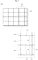
- FIG. 13 is a block diagram for describing a process of manufacturing the lens portion of the vehicular lamp according to the embodiment.
- FIG. 14 is a view illustrating the process of manufacturing the lens portion of the vehicular lamp according to the embodiment.
- FIG. 15 is a view illustrating the light source portion installed in the lens portion of the vehicular lamp according to the embodiment.
- any one element in a case in which any one element is described as being formed on (or under) another element, such a description includes both a case in which the two elements are formed to be in direct contact with each other and a case in which the two elements are in indirect contact with each other such that one or more other elements are interposed between the two elements.
- such a description may include a case in which the one element is formed on an upper side or a lower side with respect to another element.
- a vehicular lamp 1 may use a film capable of forming a three-dimensional image to improve a degree of design freedom of the vehicular lamp to enhance aesthetics.
- the vehicular lamp 1 may include a lens portion 100 , 100 a , or 100 b , and a light source portion 200 .
- the lens portion 100 , 100 a , or 100 b may include a body 110 having at least one curved surface and a film portion 120 , 120 a , or 120 b configured to form a three-dimensional image using light emitted by the light source portion 200 .
- the light source portion 200 may emit the light toward the lens portion 100 , 100 a , or 100 b . Therefore, the lens portion 100 , 100 a , or 100 b may be disposed on a line along which the light is emitted by the light source portion 200 .
- a light emitting diode may be used as a light source 210 of the light source portion 200 .
- the light source 210 may be disposed on a printed circuit board (PCB) 220 to receive power.
- PCB printed circuit board
- the lens portion 100 illustrated in FIGS. 3 to 7 may be formed by injection molding through an in-mold labelling (IML) method using a mold.
- IML in-mold labelling
- the IML, method used when the lens portion 100 is formed is a method in which a thermally shaped film is cut and inserted into the mold and the body 110 is injection molded. Therefore, the film portion 120 may be easily disposed in the body 110 in which curved surfaces are formed on both edge portions. Therefore, a delamination phenomenon occurring between the body 110 and the film portion 120 due to the curved surfaces can be prevented.
- the body 110 may be formed to include at least one curved surface.
- the body 110 may form an exterior of the lens portion 100 and may be formed of a plastic material.
- the body 110 may be formed of a resin, and the resin may include polycarbonate (PC), polymethyl methacrylate (PMMA), or the like.
- the body 110 may be formed by inserting the thermally shaped and cut film portion 120 into the mold and applying the resin on the film portion 120 .
- the film portion 120 of the lens portion 100 may include an optical film 121 and a base film 125 .
- the optical film 121 may form a three-dimensional image using the light.
- the optical film 121 may be formed on the base film 125 through a printing method.
- patterns 123 , 124 , or 124 a configured to form a three-dimensional image may also be formed on at least any one of one side and the other side of the optical film body 122 constituting the optical film 121 .
- the patterns 123 , 124 , or 124 a may be formed on at least any one of one side and the other side of the optical film body 122 through a printing method.
- the optical film 121 may be formed as an optical film 121 a according to a first example, an optical film 121 b according to a second example, an optical film 121 c according to a third example, and an optical film 121 d according to a fourth example on the basis of an arrangement position and a direction of the patterns 123 , 124 , or 124 a.
- FIG. 4 is a view illustrating the first example in which the light source portion and patterns of the optical film of the vehicular lamp according to the embodiment are disposed on a side of the light source portion.
- FIG. 4A is a view illustrating an arrangement of the light source portion and the patterns of the optical film of the vehicular lamp according to the first example of the optical film
- FIG. 4B is a view illustrating an optical image of the lens portion according to the FIG. 4A .
- FIG. 4 is the view illustrating the first example of the optical film 121 a according to a position at which the patterns are formed, and in the first example, the patterns 123 may be formed on one side of the optical film body 122 as illustrated in FIG. 4A .
- the patterns 123 of the optical film 121 a may be disposed on the optical film body 122 to face the light source 210 of the light source portion 200 .
- the light source 210 may be disposed apart from the patterns 123 .
- the plurality of patterns 123 disposed on one side of the optical film body 122 may be disposed apart from each other by a predetermined separation distance d.
- the patterns 123 may be longitudinally formed in a predetermined direction.
- the optical image of the lens portion may be formed by the optical film 121 a . That is, one portion of the optical image may be bright due to the patterns 123 , and a position at which the light source 210 is disposed may be brighter.
- FIG. 5 is a view illustrating the second example in which the light source portion and the patterns of the optical film of the vehicular lamp according to the embodiment are disposed on a side opposite the light source portion.
- FIG. 5A is a view illustrating an arrangement of the light source portion and the patterns of the optical film of the vehicular lamp according to the second example
- FIG. 5B is a view illustrating an optical image of the lens portion according to FIG. 5A .
- the patterns 124 of the optical film 121 b may be disposed on the other side of the optical film body 122 with respect to the light source 210 of the light source portion 200 .
- the plurality of patterns 124 disposed on the other side of the optical film body 122 may be disposed apart from each other by a predetermined separation distance d.
- the optical image of the lens portion may be formed by the optical film 121 b .
- the optical image formed by the optical film 121 b according to the second example is different from the optical image of the optical film 121 according to the first example.
- FIG. 6 is a view illustrating the third example in which the light source portion and the patterns of the optical film of the vehicular lamp according to the embodiment are formed on one side and the other side of the optical film.
- FIG. 6A is a view illustrating an arrangement of the light source portion and the patterns of the optical film of the vehicular lamp according to the third example
- FIGS. 6B and 6C are views illustrating optical images of the lens portion according to FIG. 6A .
- patterns 123 and 124 may be formed on one side and the other side of the optical film body 122 .
- the optical images of the lens portion may be formed by the optical film 121 c .
- the separation distance d between the patterns 123 and 124 is greater than the separation distance d between those of FIG. 6B .
- various optical images may be formed according to the separation distance d between the patterns 123 and 124 .
- FIG. 7 is a view illustrating the fourth example in which the light source portion and the patterns of the optical film of the vehicular lamp according to the embodiment are formed on one side and the other side of the optical film, and directions of the patterns are different.
- FIG. 7A is a view illustrating an arrangement of the light source portion and the patterns of the optical film of the vehicular lamp according to the fourth example
- FIGS. 7B and 7C are views illustrating optical images of the lens portion according to FIG. 7A .
- the patterns 123 and 124 a are formed on one side and the other side of the optical film body 122 , and the patterns 123 and 124 a may be formed in different directions.
- the patterns 123 may be disposed on the optical film body 122 to face the light source 210 , but are not limited thereto.
- the plurality of patterns 123 and 124 a formed on one side and the other side of the optical film body 122 may be disposed apart from each other by a predetermined separation distance d 1 .
- the patterns 123 and 124 a configured to form a three-dimensional image may be formed on one side and the other side of the optical film 121 d .
- the patterns 124 a formed on the other side may be disposed to intersect with the patterns 123 formed on one side in a longitudinal direction when seen from a line along which the light is emitted.
- the patterns 124 a may be obliquely disposed at a predetermined angle with respect to the patterns 123 disposed on one side of the optical film body 122 .
- the optical images of the lens portion illustrated in FIGS. 7B and 7C may be formed.
- the optical image of the lens portion illustrated in FIG. 7C shows that a separation distance d 1 between the patterns 123 and 124 a illustrated in FIG. 7B is greater than the separation distance d 1 between the patterns 123 and 124 a illustrated in FIG. 7C .
- a light scattering effect at an edge of the optical image formed by the optical film 121 d according to the fourth example is further improved from that of the optical image formed by the optical film 121 c according to the third example so that a smooth optical image can be formed.
- the lens portion 100 may include an adhesive layer 130 .
- the adhesive layer 130 may be interposed between the body 110 and the base film 125 .
- the adhesive layer 130 enhances adhesion by which the base film 125 is adhered to the body 110 .
- a primer of the adhesive layer 130 may be the same as a material of the body 110 .
- the lens portion 100 may further include a protection film 140 disposed on one side of the optical film 121 .
- the protection film 140 may be disposed on a side opposite the optical film body 122 with the optical film 121 interposed therebetween.
- the protection film 140 may prevent the optical film 121 from being damaged due to an external force, a high temperature, a high humidity, and the like which are externally applied.
- the protection film 140 may be formed of a material which is resistant against heat, humidity, and the like.
- the protection film 140 may also prevent the unit optical films 126 , 128 , or 129 from being damaged due to an external force, a high temperature, a high humidity, and the like which are externally applied.
- the lens portion 100 may further include a reflective layer 150 configured to increase an optical efficiency of the light by enhancing a reflectivity.
- the reflective layer 150 may be interposed between the optical film 121 and the protection film 140 .
- the reflective layer 150 may also be interposed between the plurality of unit optical films 126 , 128 , or 129 and the protection film 140 .
- the reflective layer 150 may be formed of a material containing aluminum or silver.
- the reflective layer 150 may also be disposed as a film type.
- the lens portion 100 may further include an oxidation prevention film 160 which prevents oxidation of the reflective layer 150 .
- the oxidation prevention film 160 may be interposed between the protection film 140 and the reflective layer 150 .
- the oxidation prevention film 160 may prevent the oxidation of the reflective layer 150 to improve reliability against a high temperature and a high humidity, and the like.
- the oxidation prevention film 160 may contain silicon or stainless steel.
- the oxidation prevention film 160 may be formed through a deposition method.
- FIG. 8 is a view illustrating a lens portion disposed in a vehicular lamp according to another embodiment
- FIG. 9 is a view illustrating a base film and a plurality of unit optical films of the vehicular lamp according to the embodiment.
- lens portion 100 a When the lens portion 100 a is described with reference to FIGS. 8 and 9 , components of the lens portion 100 a which are the same as those of the lens portion 100 are described with numerals which are the same as those of the components of the lens portion 100 , and specific descriptions thereof will be omitted.
- the lens portion 100 a may be formed by injection molding through an IML method using a mold.
- the lens portion 100 a may include a body 110 and the film portion 120 a.
- the film portion 120 a of the lens portion 100 a may also include the base film 125 and the plurality of unit optical films 126 disposed on one side of the base film 125 and spaced apart from each other.
- the film portion 120 a may be disposed instead of the film portion 120 illustrated in FIG. 3 .
- the unit optical films 126 may be formed on the base film 125 through a printing method.
- the plurality of unit optical films 126 may also include the optical film body 122 and patterns 123 , 124 , or 124 a formed on at least any one of one side and the other side of the optical film body 122 as described above.
- the patterns 123 , 124 , or 124 a may be formed on at least any one of one side and the other side of the optical film body 122 through a printing method.
- the plurality of unit optical films 126 may be disposed apart from each other by a predetermined separation distance d 2 . Therefore, slits 127 may be formed between the unit optical films 126 .
- the slits 127 are formed to allow an expanding surface of the unit optical film 126 to expand.
- the film portion 120 may be folded inward at a region B. Therefore, a phenomenon in which the optical film 121 is delaminated from the base film 125 at the region B may occur.
- the delamination phenomenon of the film portion 120 a due to the folding may be prevented using the unit optical films 126 disposed apart from each other.
- the unit optical films 126 should be disposed so as to maintain the predetermined separation distance d 2 .
- the separation distance d 2 between the unit optical films 126 for forming the slits 127 may be in the following range based on a width W of the unit optical film. Therefore, the lens portion 100 a may secure an illuminance while allowing the unit optical films 126 to expand.
- d 2 is in the range of 0.01 ⁇ W to 0.05 ⁇ W.
- W is a width of a unit optical film
- d 2 is a separation distance between the unit optical films.
- the separation distance d 2 between the unit optical films 126 in which the slits 127 are formed may be in the range of 0.01 to 0.05 in consideration of the above-described delamination phenomenon.
- the lens portion 100 a may further include the adhesive layer 130 , the protection film 140 , the reflective layer 150 , and the oxidation prevention film 160 .
- FIG. 11 is a view illustrating a lens portion disposed in a vehicular lamp according to still another embodiment
- FIG. 12 is a view illustrating a base film, a plurality of first unit optical films, and a plurality of second unit optical films of the vehicular lamp according to the embodiment.
- the lens portion 100 b may be formed by injection molding through an IML method using a mold.
- the lens portion 100 b may include the body 110 and the film portion 120 b.
- the film portion 120 b of the lens portion 100 may include the base film 125 , the plurality of first unit optical films 128 , and the plurality of second unit optical films 129 which are disposed apart from each other on one side of the base film 125 .
- the first unit optical films 128 and the second unit optical films 129 may form a three-dimensional image like the unit optical films 126 .
- the patterns 123 , 124 , or 124 a configured to form a three-dimensional image may be formed on at least one of one side and the other side of the optical film body 122 in each of the first unit optical films 128 and the second unit optical films 129 .
- first unit optical films 128 and the second unit optical film 129 may be disposed apart from each other by a predetermined separation distance d 3 .
- slits 127 a may be formed between the first unit optical films 128 and the second unit optical films 129 .
- the slits 127 a may be formed to have the predetermined separation distance d 3 in consideration of a delamination phenomenon as described above.
- the first unit optical film 128 may be formed in a trapezoidal shape, and the second unit optical film 129 may be formed in a triangular shape. Therefore, the film portion 120 b may be formed such that the first unit optical films 128 and the second unit optical films 129 are disposed on the base film 125 to form the slits 127 a.
- the first unit optical film 128 is formed in a trapezoidal shape and the second unit optical film 129 is formed in a triangular shape as an example, but the present invention is not limited thereto.
- the unit optical films having various shapes such as a pentagonal shape and a hexagonal shape may also be used in the film portion 120 b in consideration of a shape of the body 110 .
- the film portion 120 b may also include only any one of the first unit optical film 128 and the second unit optical film 129 or may additionally include a third unit optical film (not shown).
- the lens portion 100 b may further include the adhesive layer 130 , the protection film 140 , the reflective layer 150 , and the oxidation prevention film 160 .
- a manufacturing method S 1 of the lens portion using an IML method will be described with reference to FIGS. 13 and 14 .
- the components of the lens portion 100 , 100 a , or 100 b of the vehicular lamp 1 are described with the numerals which are the same as those of the components of the previous descriptions, and specific descriptions will be omitted.
- the lens portion manufacturing method S 1 may include disposing the optical film on the base film to form the film portion (S 10 ), shaping the film portion (S 20 ), cutting the film portion (S 30 ), inserting the film portion into a mold (S 40 ), applying a resin to form the body (S 50 ), and outputting the body (S 60 ).
- the optical film 121 may be disposed on one side of the base film 125 to form the film portion 120 .
- the optical film 121 may be formed on the base film 125 through a printing method.
- the film portion 120 a or 120 b may also be used instead of the film portion 120 according to another embodiment.
- the protective film 140 and the like may also be further disposed on one side of the film portion 120 .
- the film portion 120 may be formed using heat and the like. That is, it is preferable that a shape of the film portion 120 be formed in consideration of a shape of the lens portion 100 .
- one region of the film portion 120 may be cut in consideration of the shape of the lens portion 100 as illustrated in FIG. 11 .
- the adhesive layer 130 may be further disposed on the film portion 120 .
- the lens portion 100 formed of the body 110 and the film portion 120 is output from the mold 10 .
- the lens portion 100 , 100 a , or 100 b may be formed through the IML method through the above-described process.
- a vehicle (not shown) according to the embodiment may include the vehicular lamp 1 and a housing 2 .
- the vehicular lamp 1 is disposed in the housing 2 , and thus the vehicular lamp 1 may be installed in a vehicle using the housing 2 .
- the housing 2 may be formed in various shapes in consideration of a structure of the vehicle.
- the vehicular lamp 1 may include the lens portion 100 , 100 a , or 100 b and the light source portion 200 .
- the lens portion 100 may be formed by the injection molding through the IML method using the mold 10 .
- the body 110 of the lens portion 100 , 100 a , or 100 b may be formed to have at least one curved surface.
- the light source portion 200 may be disposed on at least any one location of one side and the other side of the body 110 .
- the light source portion 200 may include the light source 210 and the PCB 220 .
- An LED may be used as the light source 210 .
- the light source 210 may be disposed on the PCB 220 to receive power.
- the vehicle (not shown) can form a three-dimensional image through the film portion 120 , 120 a , or 120 b of the vehicular lamp 1 .
- the vehicular lamp 1 of the vehicle may form the three-dimensional image using the film portion 120 , 120 a , or 120 b and may also enhance a spatial utilization because the light source 210 is installed on one side of the body 110 . Therefore, a degree of design freedom of the vehicular lamp 1 can also be enhanced.
- FILM PORTION 121 OPTICAL FILM
- PROTECTION FILM 150 REFLECTIVE LAYER
- LIGHT SOURCE PORTION 210 LIGHT SOURCE
Abstract
Description
Claims (14)
Applications Claiming Priority (3)
| Application Number | Priority Date | Filing Date | Title |
|---|---|---|---|
| KR1020160078668A KR102565788B1 (en) | 2016-06-23 | 2016-06-23 | Impact Easing Unit and Drone having the same |
| KR10-2016-0078668 | 2016-06-23 | ||
| PCT/KR2017/006113 WO2017222227A1 (en) | 2016-06-23 | 2017-06-13 | Vehicular lamp and vehicle comprising same |
Publications (2)
| Publication Number | Publication Date |
|---|---|
| US20190143566A1 US20190143566A1 (en) | 2019-05-16 |
| US10723045B2 true US10723045B2 (en) | 2020-07-28 |
Family
ID=60783443
Family Applications (1)
| Application Number | Title | Priority Date | Filing Date |
|---|---|---|---|
| US16/310,695 Active US10723045B2 (en) | 2016-06-23 | 2017-06-13 | Vehicular lamp and vehicle comprising same |
Country Status (5)
| Country | Link |
|---|---|
| US (1) | US10723045B2 (en) |
| EP (1) | EP3477185B1 (en) |
| JP (1) | JP7005532B2 (en) |
| KR (1) | KR102565788B1 (en) |
| WO (1) | WO2017222227A1 (en) |
Families Citing this family (2)
| Publication number | Priority date | Publication date | Assignee | Title |
|---|---|---|---|---|
| EP3324103B1 (en) * | 2016-11-22 | 2021-06-16 | odelo GmbH | Vehicle lamp with an illuminating function having an effect of depth |
| GB2603775A (en) * | 2021-02-11 | 2022-08-17 | Iqs Group S R O | Injection moulding of optical components |
Citations (16)
| Publication number | Priority date | Publication date | Assignee | Title |
|---|---|---|---|---|
| US4722037A (en) * | 1986-08-15 | 1988-01-26 | Davis Charles S | Holographic device for generating multiple beams of light |
| US5383039A (en) * | 1992-12-22 | 1995-01-17 | Hughes Aircraft Company | Focused illumination, reduced light leakage floodlit center high mounted stoplight |
| US5455747A (en) * | 1993-06-24 | 1995-10-03 | Koito Manufacturing Co., Ltd. | Vehicle lighting device |
| US5571277A (en) * | 1995-06-12 | 1996-11-05 | General Motors Corporation | Automotive holographic signal lamp |
| US20060044825A1 (en) | 2002-12-06 | 2006-03-02 | Sl Lcd Co., Ltd | Lamp for vehicle |
| JP2007007988A (en) | 2005-06-30 | 2007-01-18 | Three M Innovative Properties Co | Minute structure and method for producing the same |
| US20100214797A1 (en) * | 2007-05-01 | 2010-08-26 | Koninklijke Philips Electronics N.V. | Car lighting unit for generating a beam of light and a holographic 3d image |
| DE202012007518U1 (en) | 2011-08-10 | 2012-10-24 | Faurecia Interieur Industrie | Backlit vehicle interior structure |
| DE102012003200A1 (en) | 2012-02-17 | 2013-08-22 | Audi Ag | Translucent panel of outer structure of motor vehicle, has external coating made of transparent or translucent material is coated on outer surface of light-emitting element, so that light-emitting element is translucent to light |
| KR20140078930A (en) | 2012-12-18 | 2014-06-26 | 엘지이노텍 주식회사 | Illuminating device |
| KR101503038B1 (en) | 2014-08-20 | 2015-03-16 | 주식회사 에스티씨 | Vehicle Lamp of Slim Type with 3D Multi-level Effect |
| US20150167918A1 (en) | 2013-12-18 | 2015-06-18 | Hyundai Motor Company | Light source module of lamp for vehicle |
| US20150219827A1 (en) | 2014-02-05 | 2015-08-06 | Lg Innotek Co., Ltd. | Optical member and lighting device using the same |
| US20150346422A1 (en) | 2014-06-02 | 2015-12-03 | Lg Innotek Co., Ltd. | Lighting device |
| WO2016071063A1 (en) | 2014-11-06 | 2016-05-12 | Lisa Dräxlmaier GmbH | Lighting apparatus |
| US20160229137A1 (en) * | 2013-09-27 | 2016-08-11 | Leonhard Kurz Stiftung & Co. Kg | Method, Mold Insert and Injection Mold for Producing a Plastics Molding |
Family Cites Families (4)
| Publication number | Priority date | Publication date | Assignee | Title |
|---|---|---|---|---|
| JPS59126742U (en) * | 1983-02-17 | 1984-08-25 | トヨタ自動車株式会社 | lamp lens device |
| JP2000299004A (en) * | 1999-04-15 | 2000-10-24 | Ichikoh Ind Ltd | Device for vehicle |
| KR200308620Y1 (en) * | 2002-12-06 | 2003-03-26 | 사종엽 | Lamp for vehicle |
| JP2014010918A (en) * | 2012-06-27 | 2014-01-20 | Sharp Corp | Luminaire and vehicle headlight |
-
2016
- 2016-06-23 KR KR1020160078668A patent/KR102565788B1/en active IP Right Grant
-
2017
- 2017-06-13 EP EP17815640.2A patent/EP3477185B1/en active Active
- 2017-06-13 JP JP2018566376A patent/JP7005532B2/en active Active
- 2017-06-13 WO PCT/KR2017/006113 patent/WO2017222227A1/en unknown
- 2017-06-13 US US16/310,695 patent/US10723045B2/en active Active
Patent Citations (19)
| Publication number | Priority date | Publication date | Assignee | Title |
|---|---|---|---|---|
| US4722037A (en) * | 1986-08-15 | 1988-01-26 | Davis Charles S | Holographic device for generating multiple beams of light |
| US5383039A (en) * | 1992-12-22 | 1995-01-17 | Hughes Aircraft Company | Focused illumination, reduced light leakage floodlit center high mounted stoplight |
| US5455747A (en) * | 1993-06-24 | 1995-10-03 | Koito Manufacturing Co., Ltd. | Vehicle lighting device |
| US5571277A (en) * | 1995-06-12 | 1996-11-05 | General Motors Corporation | Automotive holographic signal lamp |
| US20060044825A1 (en) | 2002-12-06 | 2006-03-02 | Sl Lcd Co., Ltd | Lamp for vehicle |
| JP2007007988A (en) | 2005-06-30 | 2007-01-18 | Three M Innovative Properties Co | Minute structure and method for producing the same |
| US20100214797A1 (en) * | 2007-05-01 | 2010-08-26 | Koninklijke Philips Electronics N.V. | Car lighting unit for generating a beam of light and a holographic 3d image |
| DE202012007518U1 (en) | 2011-08-10 | 2012-10-24 | Faurecia Interieur Industrie | Backlit vehicle interior structure |
| DE102012003200A1 (en) | 2012-02-17 | 2013-08-22 | Audi Ag | Translucent panel of outer structure of motor vehicle, has external coating made of transparent or translucent material is coated on outer surface of light-emitting element, so that light-emitting element is translucent to light |
| KR20140078930A (en) | 2012-12-18 | 2014-06-26 | 엘지이노텍 주식회사 | Illuminating device |
| US20160229137A1 (en) * | 2013-09-27 | 2016-08-11 | Leonhard Kurz Stiftung & Co. Kg | Method, Mold Insert and Injection Mold for Producing a Plastics Molding |
| US20150167918A1 (en) | 2013-12-18 | 2015-06-18 | Hyundai Motor Company | Light source module of lamp for vehicle |
| KR20150071587A (en) | 2013-12-18 | 2015-06-26 | 현대자동차주식회사 | Light source module of lamp for vehicle |
| US20150219827A1 (en) | 2014-02-05 | 2015-08-06 | Lg Innotek Co., Ltd. | Optical member and lighting device using the same |
| US20150346422A1 (en) | 2014-06-02 | 2015-12-03 | Lg Innotek Co., Ltd. | Lighting device |
| KR20150138710A (en) | 2014-06-02 | 2015-12-10 | 엘지이노텍 주식회사 | Lighting device |
| KR101503038B1 (en) | 2014-08-20 | 2015-03-16 | 주식회사 에스티씨 | Vehicle Lamp of Slim Type with 3D Multi-level Effect |
| WO2016071063A1 (en) | 2014-11-06 | 2016-05-12 | Lisa Dräxlmaier GmbH | Lighting apparatus |
| US20170349095A1 (en) | 2014-11-06 | 2017-12-07 | Lisa Draexlmaier Gmbh | Lighting apparatus |
Non-Patent Citations (2)
| Title |
|---|
| European Search Report dated May 22, 2019 issued in Application No. 17815640.2. |
| International Search Report (with English Translation) and Written Opinion dated Sep. 15, 2017 issued in Application No. PCT/KR2017/006113. |
Also Published As
| Publication number | Publication date |
|---|---|
| EP3477185A1 (en) | 2019-05-01 |
| KR102565788B1 (en) | 2023-08-10 |
| KR20180000547A (en) | 2018-01-03 |
| JP7005532B2 (en) | 2022-02-04 |
| EP3477185A4 (en) | 2019-06-19 |
| JP2019525388A (en) | 2019-09-05 |
| EP3477185B1 (en) | 2022-08-10 |
| WO2017222227A1 (en) | 2017-12-28 |
| US20190143566A1 (en) | 2019-05-16 |
Similar Documents
| Publication | Publication Date | Title |
|---|---|---|
| KR102408240B1 (en) | Illumination multilayer structure comprising a built-in surface light source | |
| KR102366619B1 (en) | Illumination multilayer structure with built-in light source | |
| CN104819423A (en) | Stereoscopic lighting device and vehicle lighting device using the same | |
| JP6987762B2 (en) | Lighting equipment and vehicle lamps including it | |
| US10006603B2 (en) | Light reflector arrangement | |
| EP3026328B1 (en) | Light source module of lamp for vehicle | |
| EP3469250B1 (en) | Lit image projection devices and lamp assemblies containing the same for generation of three dimensional images | |
| US10723045B2 (en) | Vehicular lamp and vehicle comprising same | |
| WO2011086042A1 (en) | Light cover, manufacturing method thereof, and lamp having such a cover | |
| US9791122B2 (en) | Rear lamp for vehicle | |
| CN108698536A (en) | The lighting device of vehicle | |
| US20100246203A1 (en) | System and method for exterior lighting of vehicles | |
| EP3517826B1 (en) | Lighting member using light-guiding film | |
| US8956015B2 (en) | Light-emitting apparatus and lighting system | |
| JP2008059882A (en) | Vehicle lamp | |
| US9261255B2 (en) | Light source module and lamp for vehicle having the same | |
| JP6311884B2 (en) | Lighting device | |
| CN202598398U (en) | Light emitting structure | |
| US20080106396A1 (en) | Signal light for vehicle side-view mirror | |
| JP6390396B2 (en) | LED lights | |
| US20170309205A1 (en) | Led module and sign box | |
| US20110254426A1 (en) | Wide-angle illumination light-emitting diode (led) light bulb | |
| JP6761429B2 (en) | Vehicle lighting device | |
| JP2023164074A (en) | Light emitting emblem | |
| JP2016122498A (en) | Lighting device |
Legal Events
| Date | Code | Title | Description |
|---|---|---|---|
| FEPP | Fee payment procedure |
Free format text: ENTITY STATUS SET TO UNDISCOUNTED (ORIGINAL EVENT CODE: BIG.); ENTITY STATUS OF PATENT OWNER: LARGE ENTITY |
|
| AS | Assignment |
Owner name: LG INNOTEK CO., LTD., KOREA, REPUBLIC OF Free format text: ASSIGNMENT OF ASSIGNORS INTEREST;ASSIGNORS:CHOI, YOUNG JAE;PARK, KWANG HO;JANG, JAE HYUK;AND OTHERS;REEL/FRAME:048335/0087 Effective date: 20181210 |
|
| STPP | Information on status: patent application and granting procedure in general |
Free format text: DOCKETED NEW CASE - READY FOR EXAMINATION |
|
| STPP | Information on status: patent application and granting procedure in general |
Free format text: NON FINAL ACTION MAILED |
|
| STPP | Information on status: patent application and granting procedure in general |
Free format text: RESPONSE TO NON-FINAL OFFICE ACTION ENTERED AND FORWARDED TO EXAMINER |
|
| STPP | Information on status: patent application and granting procedure in general |
Free format text: NOTICE OF ALLOWANCE MAILED -- APPLICATION RECEIVED IN OFFICE OF PUBLICATIONS |
|
| STPP | Information on status: patent application and granting procedure in general |
Free format text: PUBLICATIONS -- ISSUE FEE PAYMENT RECEIVED |
|
| STPP | Information on status: patent application and granting procedure in general |
Free format text: PUBLICATIONS -- ISSUE FEE PAYMENT VERIFIED |
|
| STCF | Information on status: patent grant |
Free format text: PATENTED CASE |
|
| MAFP | Maintenance fee payment |
Free format text: PAYMENT OF MAINTENANCE FEE, 4TH YEAR, LARGE ENTITY (ORIGINAL EVENT CODE: M1551); ENTITY STATUS OF PATENT OWNER: LARGE ENTITY Year of fee payment: 4 |