JP2017172974A - Flow rate measurement device and operational method thereof - Google Patents
Flow rate measurement device and operational method thereof Download PDFInfo
- Publication number
- JP2017172974A JP2017172974A JP2016055590A JP2016055590A JP2017172974A JP 2017172974 A JP2017172974 A JP 2017172974A JP 2016055590 A JP2016055590 A JP 2016055590A JP 2016055590 A JP2016055590 A JP 2016055590A JP 2017172974 A JP2017172974 A JP 2017172974A
- Authority
- JP
- Japan
- Prior art keywords
- flow rate
- time
- change
- time point
- target
- Prior art date
- Legal status (The legal status is an assumption and is not a legal conclusion. Google has not performed a legal analysis and makes no representation as to the accuracy of the status listed.)
- Granted
Links
Images


Abstract
Description
本発明は、流路に流れるガスの流量を計測し、この流量の変化を検出する流量測定装置およびその運転方法に関する。 The present invention relates to a flow rate measuring device that measures the flow rate of a gas flowing in a flow path and detects a change in the flow rate, and an operation method thereof.
従来、ガスメータは、ガスの流量が所定の時間に亘って継続してほぼ一定であるときに、ガス漏洩などの異常が発生したとしてガスの流路を遮断する安全機能を備えている。この安全機能では、たとえば、ガスの流量を計測し、流量が増加すると、ガス器具の使用が開始されたと判定する。そして、その時点からの経過時間をガスの使用時間として計測し、ガスの使用時間が過度に長くなると、ガス漏れの疑いがあるとしてガス流路を遮断する。 2. Description of the Related Art Conventionally, a gas meter has a safety function of shutting off a gas flow path when an abnormality such as gas leakage occurs when the gas flow rate is substantially constant for a predetermined time. In this safety function, for example, the flow rate of gas is measured, and when the flow rate increases, it is determined that the use of the gas appliance has started. Then, the elapsed time from that time is measured as the gas use time, and if the gas use time becomes excessively long, the gas flow path is shut off because there is a suspicion of gas leakage.
また、計測したガスの流量から流量の変化率および/または変化量を求め、ガスの流量変化を監視する。たとえば、ガスの流量の変化率が3%以上である、または、ガスの流量の差が51.82L/h以上であると、使用者の意図に応じたガスの流量変化があったと判定する。そして、計測していたガスの使用時間をリセットした上、ガスの使用時間の計測を再度、開始する。これにより、使用者の意図に反したガス流路の遮断が行われず、ガス器具の運転が継続される。 Further, the rate of change and / or amount of change in flow rate is obtained from the measured gas flow rate, and the change in gas flow rate is monitored. For example, if the rate of change in gas flow rate is 3% or more, or if the difference in gas flow rate is 51.82 L / h or more, it is determined that there is a change in gas flow rate according to the user's intention. Then, after resetting the measured use time of the gas, the measurement of the use time of the gas is started again. As a result, the gas flow path is not blocked against the user's intention, and the operation of the gas appliance is continued.
しかしながら、燃料電池など流量変化が小さいガス器具では、流量の変化量および変化率が小さい。このため、ガス器具が正常に運転されていても、そのガスの流量変化をガスメータは検知することができない。よって、ガスの使用時間がリセットされずに所定の時間に達し、使用者の意図に反してガス流路が遮断されてしまう。 However, in a gas appliance with a small change in flow rate such as a fuel cell, the change amount and change rate of the flow rate are small. For this reason, even if the gas appliance is operating normally, the gas meter cannot detect a change in the flow rate of the gas. Therefore, the gas usage time reaches a predetermined time without being reset, and the gas flow path is blocked against the user's intention.
このような不具合に対応するものとして、たとえば、特許文献1のガス遮断装置が知られている。このガス遮断装置では、予め設定されたしきい値として比例制御器具の流量変化の最低レベルを表す流量変化最低値(30L/h)を用いている。これにより、平均流量が変化前の流量から当該流量変化最低値以上変化した場合、流量変化を検出する。そして、この流量変化の回数をカウントし、これが予め設定された所定の回数に達した場合、実質的な流量変化ありと判定する。そして、継続時間計測用のタイマをリセットすることにより、継続時間計測のスタートポイントを更新し、ガス流路の遮断を回避している。
For example, a gas shut-off device disclosed in
しかしながら、通常、ガスメータが設けられている測定対象のガス需要家へのガスの流路は、隣家などのガス需要家へのガスの流路とも接続されている。このため、他のガス需要家に供給されるガスの流量の変化を受けて、測定対象のガス需要家に供給されるガスの流量に脈動が発生する。この脈動によってガスメータが計測するガスの流量が変動してしまう。このため、特許文献1のように、流量変化のしきい値を下げただけでは、脈動によるガスの流量変化の影響により、流量変化が小さいガス器具の使用によるガスの流量変化を適切に検出することができない。
However, normally, the gas flow path to the gas consumer of the measurement object provided with the gas meter is also connected to the gas flow path to the gas consumer such as a neighbor. For this reason, in response to a change in the flow rate of the gas supplied to another gas consumer, a pulsation occurs in the flow rate of the gas supplied to the gas consumer to be measured. This pulsation changes the flow rate of the gas measured by the gas meter. For this reason, as in
本発明はこのような課題を解決するためになされたものであり、流量変化が小さいガス器具の使用によるガスの流量変化を適切に検出することができる流量測定装置およびその運転方法を提供することを目的としている。 The present invention has been made to solve such a problem, and provides a flow rate measuring apparatus and an operation method thereof capable of appropriately detecting a change in the flow rate of gas due to the use of a gas appliance having a small flow rate change. It is an object.
本発明のある態様に係る流量測定装置は、流路に流れるガスの流量を所定の第1時間毎に計測する計測部と、所定の第2時間、離れて計測された2つの前記流量の差である対象流量差を演算する第1演算部と、前記第2時間中の前記流量の変化率である対象変化率を演算する第2演算部と、前記対象流量差が第1閾値以上であり、かつ、前記対象変化率が第2閾値以上であるときに、前記流量が変化したと判定する判定部と、を備えている。 A flow rate measuring device according to an aspect of the present invention includes a measurement unit that measures a flow rate of a gas flowing in a flow path every predetermined first time, and a difference between the two flow rates measured apart by a predetermined second time. A first calculation unit that calculates a target flow rate difference, a second calculation unit that calculates a target change rate that is a change rate of the flow rate during the second time, and the target flow rate difference is greater than or equal to a first threshold value. And the determination part which determines with the said flow volume having changed when the said object change rate is more than a 2nd threshold value is provided.
この流量測定装置では、前記計測部により計測された流量を蓄積する記憶部をさらに備え、前記第1演算部は、第1時点における前記流量の平均値である第1平均流量と、前記第1時点から前記第2時間前の第2時点における前記流量の平均値である第2平均流量との差を、前記対象流量差として求めてもよい。 The flow measurement device further includes a storage unit that accumulates the flow rate measured by the measurement unit, and the first calculation unit includes a first average flow rate that is an average value of the flow rate at a first time point, and the first A difference from the second average flow rate that is an average value of the flow rates at the second time point before the second time from the time point may be obtained as the target flow rate difference.
また、流量測定装置では、前記第2演算部は、前記第1時点と前記第2時点との間の第3時点における前記流量の平均値と、前記第3時点と前記第2時点との間の第4時点における前記流量の平均値とを用いた、前記第3時点と前記第4時点との間の流量の変化率を、前記対象変化率として求め、前記判定部は、前記対象流量差が前記第1閾値以上であり、かつ、前記対象変化率が前記第2閾値以上である、と連続で判定された回数が所定の複数回に達したときに、前記流量が変化したと判定してもよい。 Further, in the flow rate measuring device, the second calculation unit is configured to obtain an average value of the flow rate at a third time point between the first time point and the second time point, and between the third time point and the second time point. The change rate of the flow rate between the third time point and the fourth time point using the average value of the flow rate at the fourth time point is obtained as the target change rate, and the determination unit is configured to determine the target flow rate difference. Is determined to be changed when the number of times of continuous determination that the target change rate is equal to or greater than the second threshold reaches a predetermined plurality of times. May be.
流量測定装置では、前記第2演算部は、前記第1時点と前記第2時点との間の第5時点における前記流量の変化率を、前記対象変化率として求め、前記判定部は、前記対象流量差が前記第1閾値以上であり、かつ、前記対象変化率が前記第2閾値以上である、と連続で判定された回数が所定の複数回に達したときに、前記流量が変化したと判定してもよい。 In the flow rate measuring device, the second calculation unit obtains a change rate of the flow rate at a fifth time point between the first time point and the second time point as the target change rate, and the determination unit includes the target When the number of times that the flow rate difference is equal to or greater than the first threshold and the target change rate is equal to or greater than the second threshold reaches a predetermined number of times, the flow rate has changed. You may judge.
流量測定装置では、前記第2演算部は、前記第2時間中の所定の期間に複数の前記対象変化率を演算し、前記判定部は、前記対象流量差が前記第1閾値以上であり、かつ、複数の前記対象変化率のうち連続して前記第2閾値以上である前記対象変化率が所定の複数回に達したときに、前記流量が変化したと判定してもよい。 In the flow rate measuring device, the second calculation unit calculates a plurality of the target change rates in a predetermined period during the second time, and the determination unit has the target flow rate difference equal to or greater than the first threshold value, In addition, it may be determined that the flow rate has changed when the target change rate that is continuously equal to or greater than the second threshold among the plurality of target change rates reaches a predetermined number of times.
さらに、流量測定装置では、前記第1時点は、前記判定部が判定する時点より所定の時間遡った時点であってもよい。流量測定装置では、前記第1平均流量が第5閾値以上であり、かつ、前記第2平均流量が第6閾値未満であるときに前記判定部は判定してもよい。 Furthermore, in the flow rate measuring device, the first time point may be a time point that is a predetermined time later than the time point determined by the determination unit. In the flow rate measuring device, the determination unit may determine when the first average flow rate is equal to or greater than a fifth threshold value and the second average flow rate is less than a sixth threshold value.
流量測定装置は、前記計測部により計測された流量が0から増加した時、または、前記判定部により前記流量が変化した判定された時からの経過時間を計測するタイマと、前記経過時間が第7閾値に達したときに前記流路を遮断する遮断部と、を備え、前記経過時間は、前記判定部により前記流量が変化したと判定した時にリセットされてもよい。 The flow rate measuring device includes a timer that measures an elapsed time from when the flow rate measured by the measurement unit increases from 0 or when the determination unit determines that the flow rate has changed, A blocking unit that blocks the flow path when the threshold value is reached, and the elapsed time may be reset when the determination unit determines that the flow rate has changed.
流量測定装置は、前記判定部とは別に、前記流量の変化を検出する検出部をさらに備え、前記流量が0であるとき、または、前記検出部により前記流量の変化が検出されたとき、前記記憶部に蓄積されていた前記流量を消去してもよい。 The flow measurement device further includes a detection unit that detects a change in the flow rate separately from the determination unit, and when the flow rate is 0 or when the change in the flow rate is detected by the detection unit, The flow rate accumulated in the storage unit may be erased.
本発明のある態様に係る流量測定装置の運転方法では、流路に流れるガスの流量を所定の第1時間毎に計測し、所定の第2時間、離れて計測された2つの前記流量の差である対象流量差を演算し、前記第2時間中の前記流量の変化率である対象変化率を演算し、前記対象流量差が第1閾値以上であり、かつ、前記対象変化率が第2閾値以上であるときに、前記流量が変化したと判定する。 In the operation method of the flow rate measuring device according to an aspect of the present invention, the flow rate of the gas flowing in the flow path is measured every predetermined first time, and the difference between the two flow rates measured apart by a predetermined second time is measured. The target flow rate difference is calculated, the target change rate that is the rate of change of the flow rate during the second time is calculated, the target flow rate difference is greater than or equal to a first threshold value, and the target change rate is the second When it is equal to or greater than the threshold, it is determined that the flow rate has changed.
本発明は、以上の構成を有し、流量変化が小さいガス器具の使用によるガスの流量変化を適切に検出することができる流量測定装置およびその運転方法を提供することができるという効果を奏する。 The present invention has the above-described configuration, and produces an effect that it is possible to provide a flow rate measuring device that can appropriately detect a change in the flow rate of gas due to the use of a gas appliance having a small flow rate change, and an operation method thereof.
本発明の上記目的、他の目的、特徴および利点は、添付図面参照の下、以下の好適な実施態様の詳細な説明から明らかにされる。 The above object, other objects, features and advantages of the present invention will become apparent from the following detailed description of preferred embodiments with reference to the accompanying drawings.
以下、本発明の実施の形態を、図面を参照しながら具体的に説明する。なお、以下では全ての図面を通じて同一または相当する要素には同一の参照符号を付して、その重複する説明を省略する。 Hereinafter, embodiments of the present invention will be specifically described with reference to the drawings. In the following description, the same or corresponding elements are denoted by the same reference symbols throughout the drawings, and redundant description thereof is omitted.
(実施の形態1)
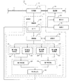
まず、実施の形態1に係る流量測定装置10の構成について、図1を参照して説明する。流量測定装置10は、ガスの流路11に設けられている。ガスの流路11は、ガス供給源(図示せず)と消費者の需要家とを繋ぎ、ガス供給源から需要家に設けられたガス器具(図示せず)にガスを供給する管路である。
(Embodiment 1)
First, the configuration of the
ガス器具としては、燃料電池などが挙げられる。この燃料電池は、正常に運転されているにも関わらず、ガスの流量変化が小さく、この流量変化が長時間に亘って検知されずに、ガスの流路11が遮断されてしまうことを防止するため、ある時間(たとえば、10時間)毎に所定の変動パターンでガスの消費量を一時的に変動させている。これにより、流路11からガス器具に供給されるガスの流量が所定の変動パターンで変動する。
Examples of the gas appliance include a fuel cell. Although the fuel cell is operating normally, the change in the gas flow rate is small, and the change in the flow rate is not detected over a long period of time, thereby preventing the
たとえば、図2に示すように、ガス器具は、流路11から供給されるガスの流量を、所定の時間(第1増加時間)Ti1に亘って所定の変化率で基準流量から増加させてから、所定の時間Th(たとえば、1分)に亘り一定の流量(高流量)に維持する。その後、ガスの流量を、所定の時間(減少時間)Td(たとえば、39秒)に亘って所定の変化率で減少させて、さらに、所定の時間Tl(たとえば、111秒)に亘り一定の流量(低流量)に維持してから、所定の時間(第2増加時間)Ti2に亘って所定の変化率で基準流量まで増加させる。これにより、流量が一定である2つの区間と、これに挟まれた、流量が所定の割合で変化する区間とを有する、流量の変動パターンが形成される。
For example, as shown in FIG. 2, the gas appliance increases the flow rate of the gas supplied from the
以下、一般家庭に供給されるガスの使用量を求めるガスメータ12に本発明に係る流量測定装置10を適用した場合について説明する。ただし、流量測定装置10はガスメータ12に限定されない。ガスメータ12は、遮断部13、表示部14、通信部15および流量測定装置10を備えている。
Hereinafter, the case where the flow
遮断部13は、流量測定装置10からの制御指示に基づきガスの流路11を開放したり塞いだりする。たとえば、遮断部13は、遮断弁を有し、流量測定装置10からガス器具までの間でガス漏れなどの異常が検出された場合、遮断弁で流路11を塞ぎ、ガスの流れを遮断する。
The blocking
表示部14は、たとえば、ガスメータ12の表面に設けられた表示盤であり、流量測定装置10から出力された総消費量などの情報を表示する。通信部15は、たとえば、通信器具であって、流量測定装置10から出力された総消費量などの情報をガス供給事業者に通信回線を介して送信する。
The
流量測定装置10は、計測部16、制御器17および記憶部18を備えている。計測部16は、ガスの流路11に設けられ、流路11を単位時間当たりに通過するガスの体積または質量((瞬時)流量)を計測する流量計であり、その計測方法に超音波式が採用される。計測部16は、制御部22と通信可能に信号線により接続されている。計測部16は、たとえば、2秒などの所定の第1時間毎にガスの流量を計測し、その計測した流量(計測流量)を制御部22へ出力する。また、記憶部18は、たとえば、バッファであって、計測部16により計測された流量を蓄積する。
The
制御器17は、第1演算部19、第2演算部20および判定部21を備えている。さらに、制御器17は、制御部22および管理部23を備えていてもよい。制御器17は、演算処理機能を備え、たとえば、マイクロコントローラ、CPU、MPU、論理回路、PLC(Programmable Logic Controller)等が例示される。なお、制御部22は、集中制御を行う単独の制御器で構成されていてもよく、互いに協働して分散制御を行う複数の制御器で構成されていてもよい。また、制御器17は、実行するためのプログラムおよび各種データを記憶するメモリ(図示せず)を備えていてもよい。このメモリは、制御部22からアクセス可能であれば、制御器17に内蔵されていてもよいし、制御器17の外に設けられていてもよい。
The controller 17 includes a
制御部22は、計測部16による計測流量に基づいて遮断部13、表示部14および通信部15を制御する。たとえば、制御部22は、計測流量を積算し、その積算値を需要家における消費量(総消費量)として表示部14や通信部15へ出力する。また、制御部22は、経過時間を計測するタイマ31を有している。制御部22は、計測流量に基づいてガス器具の運転開始を検出し、運転開始からの経過時間をタイマ31により計測する。また、制御部22は、後述する判定部21によりガス器具の運転継続が判定されたら、経過時間をリセットする。そして、経過時間が第7閾値に達したら、流路11の遮断指示を遮断部13へ出力する。
The
管理部23は、計測部16から入力された計測流量を管理する。たとえば、計測部16から入力された計測流量を取得して記憶部18に順次、記憶する。また、管理部23は、記憶部18に蓄積された計測流量を第1演算部19および第2演算部20に適宜、出力する。
The
第1演算部19は、所定の第2時間p1、離れて計測された2つの流量の差(対象流量差)を演算する。第1演算部19は、2つの流量の一方を取得する第1流量取得部24、および、他方を取得する第2流量取得部25を備える。この2つの流量はそれぞれ、瞬時流量である計測流量であってもよいし、複数の計測流量の平均値であってもよい。
The
所定の第2時間p1は、図2に示す流量の変動パターンのうち、高流量と低流量との差が最も大きいため、この流量の差を検出できるように設定することが好ましい。この場合、所定の第2時間p1は、ガス器具に供給されるガスの流量を高流量から低流量に減少させる間の減少時間Td以上であり、高流量から低流量までの間の時間(Th+Td+Tl)以下に設定される。ただし、所定の第2時間p1は、ガス器具の特定の流量の変動パターンを検出できれば、これに限定されない。たとえば、基準流量と高流量との差を検出できるように、所定の第2時間p1を第1増加時間Ti1以上に設定してもよい。または、低流量と基準流量との差を検出できるように、所定の第2時間p1を第2増加時間Ti2以上に設定してもよい。 The predetermined second time p1 is preferably set so that the difference between the high flow rate and the low flow rate is the largest in the flow rate variation pattern shown in FIG. 2, so that this flow rate difference can be detected. In this case, the predetermined second time p1 is equal to or longer than the decrease time Td during which the flow rate of the gas supplied to the gas appliance is decreased from the high flow rate to the low flow rate, and the time between the high flow rate and the low flow rate (Th + Td + Tl). ) Set to: However, the predetermined second time p1 is not limited to this as long as a specific flow rate variation pattern of the gas appliance can be detected. For example, the predetermined second time p1 may be set to be equal to or longer than the first increase time Ti1 so that the difference between the reference flow rate and the high flow rate can be detected. Alternatively, the predetermined second time p1 may be set to be equal to or longer than the second increase time Ti2 so that the difference between the low flow rate and the reference flow rate can be detected.
第2演算部20は、所定の第2時間p1中の流量の変化率(対象変化率)を演算する。対象変化率は、たとえば、ある時間離れて計測された2つの流量の平均変化率であり、(流量の差)/(時間の差)で表せる。時間の差は2つの流量をそれぞれ計測した時間の差である。第2演算部20は、2つの流量の一方の取得する第3流量取得部26、および、他方を取得する第4流量取得部27を備える。この2つの流量はそれぞれ、瞬時流量である計測流量であってもよいし、複数の計測流量の平均値であってもよい。
The
判定部21は、対象流量差が第1閾値以上であり、かつ、対象変化率が第2閾値以上であるときに流量が変化したと判定する。たとえば、判定部21は第1判定部28、第2判定部29および第3判定部30を備える。
The
第1判定部28は、対象流量差が第1閾値以上であると判定すると、判定結果を第3判定部30へ出力する。第2判定部29は、対象変化率が第2閾値以上であると判定すると、判定結果を第3判定部30へ出力する。第3判定部30は、第1判定部28からの判定結果および第2判定部29からの判定結果を得ると、ガス器具に供給されている流量が変化したと判定し、この判定結果を制御部22に出力する。
If the
次に、流量測定装置10の運転方法を、図2〜図4を参照して説明する。図3に示す流量測定装置10の運転方法は、制御器17により実行される。まず、制御器17の制御部22は、計測部16から計測流量を所定の第1時間毎に取得する(ステップS1)。たとえば、図2に示す現時点t0において最新の計測流量が計測部16により計測されて制御部22へ出力される。制御部22は、計測流量を積算し、この積算値をガスの総消費量として表示部14および通信部15へ出力する。これにより、ガスの総消費量が表示部14に表示されると共に、通信部15によりガス供給事業者に報知される。
Next, an operation method of the flow
また、制御部22は、計測流量に基づきガス器具の運転を監視する(ステップS2)。たとえば、計測流量が0であれば、制御部22はガス器具が停止していると判定する(ステップS2:NO)。この場合、ステップS1の処理に戻り、ガス器具の運転の監視を継続する。
Further, the
一方、計測流量が0から増加すると、制御部22はガス器具が運転を開始したと判定する(ステップS2)。これにより、制御部22は、この開始時点からの経過時間をタイマ31によりカウントし、経過時間をガス器具の運転時間として記憶する(ステップS3)。
On the other hand, when the measured flow rate increases from 0, the
さらに、計測部16からの計測流量は、管理部23により記憶部18に格納される。これにより、記憶部18には、最新の計測流量およびこれから遡って取得された一定期間または一定個数の複数の計測流量が蓄積される。また、管理部23は、第1演算部19および第2演算部20のそれぞれが必要な計測流量を記憶部18から取得して、各演算部19、20に出力する。
Further, the measured flow rate from the
第1演算部19は、管理部23から出力された計測流量により対象流量差を演算する(ステップS4)。たとえば、第1演算部19の第1流量取得部24が、図2の第1区間時間b1に蓄積された計測流量を管理部23から取得し、この平均値(第1平均流量)を演算する。この第1区間時間b1は、第1時点t1とこの第1時点t1から第1区間時間b1遡った第1’時点t1’との間の時間である。第1時点t1は、判定部21が判定する現時点t0より所定の時間d1遡った時点である。なお、第1時点t1は、現時点t0であってもよい。
The
第2流量取得部25が、第2区間時間b2に蓄積された計測流量を管理部23から取得し、この平均値(第2平均流量)を演算する。この第2区間時間b2は、第2時点t2とこの第2時点t2から第2区間時間b2遡った第2’時点t2’との間の時間である。第2時点t2は、現時点t0より所定の時間d2遡った時点であり、第1時点t1から所定の第2時間p1前の時点である。つまり、所定の第2時間p1は、第1時点t1と第2時点t2との間の時間である。
The second flow
第1演算部19は、第1流量所得部からの第1平均流量と、第2流量所得部からの第2平均流量との差を演算し、この差を対象流量差として判定部21へ出力する。なお、第1流量所得部による第1平均流量の演算、第2流量所得部による第2平均流量の演算、ならびに、第1演算部19による対象流量差の演算および出力は、所定の第1時間毎に行われる。
The
また、第2演算部20は、管理部23から出力された計測流量により対象変化率を演算する(ステップS5)。たとえば、第2演算部20の第3流量取得部26は、第3区間時間b3に蓄積された計測流量を管理部23から取得し、この平均値(第3平均流量)を演算する。この第3区間時間b3は、たとえば、30秒であって、第3時点t3とこの第3時点t3から第3区間時間b3遡った第3’時点t3’との間の時間である。第3時点t3は、計測部16により流量が計測された現時点t0より所定の時間d3遡った時点であり、第1時点t1と第2時点t2との間の時点である。
Moreover, the 2nd calculating
第4流量取得部27は、第4区間時間b4に蓄積された計測流量を管理部23から取得し、この平均値(第4平均流量)を演算する。この第4区間時間b4は、たとえば、30秒であって、第4時点t4とこの第4時点から第4区間時間b4遡った第4’時点t4’との間の時間である。第4時点t4は、現時点t0より所定の時間d4遡った時点であり、第3時点t3と第2時点t2との間の時点である。なお、第4時点t4が第2時間p1にあれば、第4’時点t4’が第2時間p1の中になくても、第4時点t4と第4’時点t4’との間の第4平均流量に基づく流量の変化率は、所定の第2時間p1中における対象変化率に含まれる。
The fourth flow
第2演算部20は、第3平均流量と第4平均流量との差を、第3時点t3と第4時点t4との差で割って、この商を対象変化率として判定部21へ出力する。なお、第3流量所得部による第3平均流量の演算、第4流量所得部による第4平均流量の演算、ならびに、第2演算部20による対象変化率の演算および出力は、所定の第1時間毎に行われる。
The
判定部21は、第1演算部19からの対象流量差および第2演算部20からの対象変化率に基づいて、流量が変化したか否かを判定する(ステップS6)。具体的には、判定部21の第1判定部28は、対象流量差が第1閾値以上であるか否かを判定する。そして、対象流量差が第1閾値以上であれば、この判定結果を第3判定部30に出力する。
The
第1閾値は、たとえば、図2に示す高流量と低流量との流量の差を検出できるようにこの差以下に設定されたり、基準流量と高流量との流量の差を検出できるようにこの差以下に設定されたり、基準流量と低流量との流量の差を検出できるようにこの差以下に設定されたりする。なお、図2に示す流量の変動パターンでは、高流量と低流量との流量の差が、基準流量と高流量とおよび基準流量と低流量との流量の差より大きい。このため、基準流量と高流量または低流量との差以下に第1閾値を設定すれば、高流量と低流量との流量の差も検出することができる。 For example, the first threshold is set to be equal to or smaller than this difference so that the difference between the high flow rate and the low flow rate shown in FIG. 2 can be detected, or the first threshold value can be detected so that the difference between the reference flow rate and the high flow rate can be detected. It is set below the difference, or set below this difference so that the difference in flow rate between the reference flow rate and the low flow rate can be detected. In the flow rate variation pattern shown in FIG. 2, the difference between the high flow rate and the low flow rate is larger than the difference between the reference flow rate and the high flow rate and between the reference flow rate and the low flow rate. For this reason, if the first threshold value is set to be equal to or less than the difference between the reference flow rate and the high flow rate or the low flow rate, the flow rate difference between the high flow rate and the low flow rate can also be detected.
第2判定部29は、対象変化率が第2閾値以上であるか否かを判定する。そして、対象変化率が第2閾値以上であれば、この判定結果を第3判定部30に出力する。第2閾値は、高流量と低流量との間の流量の変化率を検出できるようにこの変化率以下に設定されたり、基準流量と高流量との流量の変化率を検出できるようにこの変化率以下に設定されたり、基準流量と低流量との流量の変化率を検出できるようにこの変化率以下に設定されたりする。なお、図2に示す流量の変動パターンでは、高流量から低流量へ減少する流量の変化率は、基準流量から高流量へおよび低流量から基準流量へ増加する流量の変化率より小さい。このため、減少する流量の変化率以下に第2閾値を設定すれば、増加する流量の変化率を検出することができる。
The
第3判定部30は、第1判定部28からの判定結果および第2判定部29からの判定結果が連続で出力された回数が第3閾値に達したときに流量が変化したと判定する。つまり、対象流量差および対象変化率は第1時間毎に連続して判定部21に出力され、第1判定部28および第2判定部29は対象流量差または対象変化率に基づいて第1時間毎に連続して判定する。これに対して、第1判定部28および第2判定部29の判定結果は条件を満たしたときのみ出力される。この両方の判定結果が出力され、かつ、その連続回数が第3閾値に達すると、第3判定部30は流量変化があったと判定する。
The
たとえば、図4に示す計測流量では、ガス器具から出力される流量の変動パターンに加えて、周りの環境により影響される流量の脈動が見られる。この図4では、丸印で示す第1判定部28の判定結果のように、時間m1から時間m3までの間、および、時間m4から時間m8までの間では、対象流量差が第1閾値以上であるとの判定結果が第1判定部28から連続的に出力されている。この時間m1から時間m3までの間は、基準流量から高流量へ流量が増加している際の対象流量差が第1閾値以上になり、この判定結果が第1時間毎に出力されている。時間m4から時間m8までの間は、高流量から低流量へ流量が減少している際の対象流量差が第1閾値以上になり、この判定結果が第1時間毎に出力されている。このように、脈動により流量が変化しているため、広い範囲に亘って流量の変化が検出されている。
For example, in the measured flow rate shown in FIG. 4, in addition to the fluctuation pattern of the flow rate output from the gas appliance, pulsation of the flow rate affected by the surrounding environment is seen. In FIG. 4, as in the determination result of the
また、三角印で示す第2判定部29の判定結果のように、時間m2から時間m3までの間、および、時間m5から時間m7までの間、対象変化率が第2閾値以上であるとの判定結果が第2判定部29から連続的に出力されている。この時間m2から時間m3までの間は、基準流量から高流量へ流量が増加している際の対象変化率が第2閾値以上になり、この判定結果が第1時間毎に出力されている。時間m5から時間m7までの間は、高流量から低流量へ流量が減少している際の対象変化率が第2閾値以上になり、この判定結果が第1時間毎に出力されている。
In addition, as in the determination result of the
このように、時間m2から時間m3までの間、および、時間m5から時間m7までの間では、第1判定部28および第2判定部29から共に判定結果が連続的に出力されている。たとえば、第3閾値が7回に設定されている場合、時間m5から時間m7までの間の時間m6で連続回数が7回になる。ここで、第3判定部30は、第1判定部28および第2判定部29の判定結果の連続回数が第3閾値に達したとし、流量が変化したと判定する(ステップS6:Yes)。
As described above, the determination results are continuously output from the
そして、第3判定部30はこの判定結果を制御部22へ出力する。制御部22は、流量が変化したとの判定結果により、使用者の意図に沿ったガス器具の運転が継続されているものとして、記憶されているガス器具の運転時間をクリアして0に設定する(ステップS7)。その後、制御部22は、この運転継続の判定時点からの経過時間を再びタイマ31によりカウントし直し、経過時間をガス器具の運転時間として記憶する(ステップS3)。以下、ステップS4〜S6の処理を行う。
Then, the
一方、制御部22は、第3判定部30から流量が変化したとの判定結果が出力されない場合(ステップS6:NO)、ガス器具の運転時間が第7閾値に達したか否かを判定する(ステップS8)。運転時間が第7閾値に達していない間(ステップS8:NO)、流量の変化を監視する(ステップS4〜S6)。
On the other hand, when the determination result that the flow rate has changed is not output from the third determination unit 30 (step S6: NO), the
これに対して、運転時間が第7閾値に達すると(ステップS8:YES)、制御部22は遮断部13によりガスの流路11を遮断する(ステップS9)。ステップS1の処理に戻る。これにより、ガス漏れなどの異常事態を的確に判断して安全が確保される。
On the other hand, when the operating time reaches the seventh threshold (step S8: YES), the
上記実施の形態によれば、対象流量差が第1閾値以上であり、かつ、対象変化率が第2閾値以上であるときに流量が変化したと判定する。これにより、ガスの流量が脈動していても、燃料電池のようなガスの流量変化が小さなガス器具の使用によるガスの流量変化を適切に検出することができる。 According to the above embodiment, it is determined that the flow rate has changed when the target flow rate difference is equal to or greater than the first threshold value and the target change rate is equal to or greater than the second threshold value. Thereby, even if the gas flow rate is pulsating, it is possible to appropriately detect the gas flow rate change due to the use of a gas appliance having a small gas flow rate change such as a fuel cell.
また、第1演算部19は、対象流量差に第1平均流量および第2平均流量を用いている。また、第2演算部20は、対象変化率に第3平均流量および第4平均流量を用いている。さらに、判定部21は、第1判定部28による判定結果および第2判定部29による判定結果が複数回、連続で得られた場合に流量が変化したと判定している。よって、脈動による誤判定を低減し、ガス器具によるガスの流量変化をより精度良く検出することができる。
Moreover, the
さらに、判定部21により流量が変化したと判定した時にガス器具の運転時間がリセットされる。これにより、使用者の意図に沿ってガス器具が正常に運転されているにかかわらず、小さなガスの流量変化が検出されずにガスの流路11が遮断されることを防止することができる。
Furthermore, when the
(実施の形態2)
実施の形態2に係る流量測定装置10の構成および運転方法について、図5を参照して説明する。第2演算部20は、第5時点t5における流量の変化率を対象変化率として演算している。この第5時点t5は第1時点t1と第2時点t2との間の時点である。
(Embodiment 2)
The configuration and operation method of the flow
たとえば、対象変化率は、第5時点t5における計測流量と、第5’時点t5’における計測流量との平均変化率である。第5’時点t5’は第5時点t5から第1時間後の時点である。なお、第5時点t5と第5’時点t5’との間は第1時間より長くてもよい。 For example, the target change rate is an average change rate between the measured flow rate at the fifth time point t5 and the measured flow rate at the fifth 'time point t5'. The fifth time point t5 'is a time point after the first time from the fifth time point t5. Note that the interval between the fifth time point t5 and the fifth 'time point t5' may be longer than the first time.
具体的には、第2演算部20の第3流量取得部26は第5時点t5の計測流量を管理部23から取得し、第4流量取得部27は第5’時点t5’の計測流量を管理部23から取得する。そして、第2演算部20は、第5時点t5の計測流量と第5’時点t5’の計測流量との差を、第5時点t5と第5’時点t5’との差(第1時間)で割って、この商を対象変化率として判定部21へ出力する。判定部21は、対象流量差が第1閾値以上であり、かつ、対象変化率が第2閾値以上であると連続で判定された回数が第3閾値に達したときに流量が変化したと判定する。
Specifically, the third flow
上記実施の形態によれば、第2演算部20は対象変化率に第5時点t5および第5’時点t5’の計測流量を用い、これに基づき判定部21は流量の変化を判定している。よって、より迅速に流量変化の判定を行うことができる。
According to the above embodiment, the
(実施の形態3)
実施の形態3に係る流量測定装置10の構成および運転方法について、図6を参照して説明する。第2演算部20は、第2時間p1中の所定の期間における複数の対象変化率を演算する。この所定の期間は、第1時点t1と第2時点t2との間の第6時点t6と第6’時点t6’との間の期間であって、第1時間より長い。
(Embodiment 3)
The configuration and operation method of the flow
具体的には、第2演算部20の第3流量取得部26は第6時点t6の計測流量を管理部23から取得し、第4流量取得部27は第6時点t6から第1時間後の第7時点t7の計測流量を管理部23から取得する。そして、第2演算部20は、これらの計測流量の差を第1時間で割って、この商を対象変化率として判定部21へ出力する。また、第3流量取得部26は第7時点t7の計測流量を管理部23から取得し、第4流量取得部27は第7時点t7から第1時間後の第8時点t8の計測流量を管理部23から取得する。そして、第2演算部20は、これらの計測流量の差を第1時間で割って、この商を対象変化率として判定部21へ出力する。
Specifically, the third flow
この対象変化率の演算および出力を、第6時点t6から第6’時点t6’までの所定の期間における計測流量について実行する。この実施の形態では、5つの対象変化率が演算されて、判定部21へ出力される。なお、第6時点t6と第7時点t7との差、および、第7時点t7と第8時点t8との差など、対象変化率に用いられる計測流量の時間間隔は第1時間より長くてもよい。
This calculation and output of the target change rate is executed for the measured flow rate during a predetermined period from the sixth time point t6 to the sixth 'time point t6'. In this embodiment, five target change rates are calculated and output to the
そして、判定部21は、対象流量差が第1閾値以上であり、かつ、複数の対象変化率のうち連続して第2閾値以上である対象変化率が複数回(第4閾値)に達したときに、流量が変化したと判定する。すなわち、判定部21の第1判定部28は、対象流量差が第1閾値以上であるか否かを判定する。そして、対象流量差が第1閾値以上であれば、この判定結果を第3判定部30に出力する。
Then, the
第2判定部29は、複数の対象変化率のそれぞれが第2閾値以上であるか否かを判定する。この実施の形態では、5つの対象変化率が第2演算部20から出力される。このため、この各対象変化率のそれぞれが第2閾値以上であるか否かを判定する。このうち、連続している第2閾値以上の対象変化率の個数を求め、この個数が第4閾値に達したら、この判定結果を第3判定部30に出力する。第3判定部30は、第1判定部28から判定結果が出力され、かつ、第2判定部29から判定結果が出力されると、流量が変化したと判定する。
The
上記実施の形態によれば、対象流量差が第1閾値以上である場合に、所定期間における第4閾値以上の対象変化率が連続して第2閾値以上であると、流量が変化したと判定する。よって、より迅速に流量の判定を行うことができる。 According to the above embodiment, when the target flow rate difference is equal to or greater than the first threshold, if the target change rate equal to or greater than the fourth threshold in the predetermined period is continuously equal to or greater than the second threshold, it is determined that the flow rate has changed. To do. Therefore, the flow rate can be determined more quickly.
(実施の形態4)
実施の形態4に係る流量測定装置10では、第1平均流量が第5閾値以上であり、かつ、第2平均流量が第6閾値未満であるときに判定部21は判定する。この判断基準は、実施の形態1〜3の流量測定装置10に採用することができる。また、この判定部21以外に、流量測定装置10は、図7に示すように、通常の流量の変化の検出部32を備えていてもよい。検出部32は、たとえば、ガスの流量の変化率が3%以上である場合、または、ガスの流量の差が51.82L/h以上である場合、ガスの流量変化を検出する。
(Embodiment 4)
In the flow
たとえば、流量変化が小さい燃料電池などの対象のガス器具が運転している際に、流量変化が大きい他のガス器具が運転している。この場合、他のガス器具によるガスの流量の変化は、第2平均流量が第6閾値以上になり、対象のガス器具によるガスの流量の変化より大きく変化する。このため、検出部32が流量変化を検出可能なガスの流量範囲では、判定部21は流量の変化の判定を行わない。
For example, when a target gas appliance such as a fuel cell having a small flow rate change is operating, another gas appliance having a large flow rate change is operating. In this case, the change in the gas flow rate due to the other gas appliances is greater than the change in the gas flow rate due to the target gas appliance because the second average flow rate is equal to or greater than the sixth threshold value. For this reason, the
また、流量変化が小さい対象のガス器具であっても運転していれば、第1平均流量が第5閾値以上になる。このため、対象のガス器具に供給されていないガスの流量範囲では、判定部21は流量の変化の判定を行わない。
Moreover, if it is driving | operating even if it is a target gas appliance with a small flow volume change, a 1st average flow volume will become 5th threshold value or more. For this reason, in the flow range of the gas that is not supplied to the target gas appliance, the
一方、第1平均流量が第5閾値以上であり、かつ、第2平均流量が第6閾値未満である場合、対象のガス器具が運転しているが、他のガス器具は運転していない。このような場合に、判定部21は、第1演算部19からの対象流量差および第2演算部20からの対象変化率に基づいて対象のガス器具のガスの流量変化を判定する。
On the other hand, when the first average flow rate is equal to or greater than the fifth threshold value and the second average flow rate is less than the sixth threshold value, the target gas appliance is operating, but other gas appliances are not operating. In such a case, the
上記実施の形態によれば、他のガス器具が運転せず、対象のガス器具が運転している場合に、判定部21が対象のガス器具のガスの流量変化を検出する。よって、判定部21および検出部32から共にガスの流量変化が検出されることがなく、ガスの流量変化に対する処理を簡素がすることができる。
According to the above embodiment, when the other gas appliance is not operated and the target gas appliance is operating, the
(実施の形態5)
実施の形態5に係る流量測定装置10では、判定部21とは別に、図7に示す流量の変化を検出する検出部32をさらに備えている。また、計測部16により計測された流量が0であるとき、または、検出部32により流量の変化が検出されたとき、記憶部18に蓄積されていた流量を消去する。これは、実施の形態1〜4の流量測定装置10に採用することができる。
(Embodiment 5)
The
検出部32は、判定部21が対象としている流量の変化より大きな流量変化を検出する。たとえば、ガスの流量の変化率が3%以上である、または、ガスの流量の差が51.82L/h以上である場合、流量変化であると検出する。
The
記憶部18は、管理部23により順次記憶された計測流量を蓄えている。これに対し、制御部22は、計測流量を監視し、計測流量が0になったら、記憶部18に蓄えられている複数の計測流量のデータを管理部23により消去する。この消去は、計測流量が0になった時と0から増加する時との間の計測流量が0である期間に行われればよい。これにより、ガス器具の運転が終了した後にこれとは別のガス器具が運転を開始した場合、別のガス器具の流量の判定に、この前に運転していた別のガス器具の計測流量が用いられることが防がれる。よって、より精度良く流量の変化を検出することができる。
The
また、検出部32が流量の変化を検出するまでに記憶部18に蓄えられた計測流量は、検出部32の検出対象のデータである。このため、このデータを消去することにより、判定部21の判定対象のガス器具の流量の変化判定に検出部32の検出対象のデータが含まれない。よって、より精度良く流量の変化を検出することができる。
The measured flow rate stored in the
(その他の実施の形態)
上記全ての実施の形態の流量測定装置10が、判定部21とは別に、流量の変化を検出する検出部32をさらに備えていてもよい。この場合、この検出部32が流量の変化を検出したときに、判定部21が流量の変化を判定すると、判定部21の判定を不成立と処理してもよい。これにより、流量変化の判定結果を一本化することにより、処理の効率化が図られる。
(Other embodiments)
The flow
また、上記全ての実施の形態では、第3判定部30は、第1判定部28からの判定結果および第2判定部29からの判定結果を得ると、ガス器具に供給されている流量が変化したと判定し、この判定結果を制御部22に出力した。この判定のタイミングまたは判定結果を出力するタイミングを他の任意の処理タイミングに合わせてもよい。たとえば、流量測定装置10の他の部の動作タイミングが第1時間とは異なる時間間隔で行われている場合、この異なる時間間隔で第3判定部30は判定結果を出力してもよい。これにより、流量変化の判定を他の動作と連動させることができる。
In all the above embodiments, when the
なお、上記全実施の形態は、互いに相手を排除しない限り、互いに組み合わせてもよい。上記説明から、当業者にとっては、本発明の多くの改良や他の実施の形態が明らかである。従って、上記説明は、例示としてのみ解釈されるべきであり、本発明を実行する最良の態様を当業者に教示する目的で提供されたものである。本発明の精神を逸脱することなく、その構造および/または機能の詳細を実質的に変更できる。 Note that all the above embodiments may be combined with each other as long as they do not exclude each other. From the foregoing description, many modifications and other embodiments of the present invention are apparent to persons skilled in the art. Accordingly, the foregoing description should be construed as illustrative only and is provided for the purpose of teaching those skilled in the art the best mode of carrying out the invention. The details of the structure and / or function may be substantially changed without departing from the spirit of the invention.
本発明の流量測定装置およびその運転方法は、流量変化が小さいガス器具の使用によるガスの流量変化を適切に検出することができる流量測定装置およびその運転方法等として有用である。 The flow rate measuring device and the operating method thereof according to the present invention are useful as a flow rate measuring device capable of appropriately detecting a change in gas flow rate due to the use of a gas appliance having a small flow rate change, and an operating method thereof.
10 :流量測定装置
11 :流路
13 :遮断部
16 :計測部
18 :記憶部
19 :第1演算部
20 :第2演算部
21 :判定部
31 :タイマ
32 :検出部
DESCRIPTION OF SYMBOLS 10: Flow measuring device 11: Flow path 13: Blocking part 16: Measuring part 18: Memory | storage part 19: 1st calculating part 20: 2nd calculating part 21: Determination part 31: Timer 32: Detection part
Claims (10)
所定の第2時間、離れて計測された2つの前記流量の差である対象流量差を演算する第1演算部と、
前記第2時間中の前記流量の変化率である対象変化率を演算する第2演算部と、
前記対象流量差が第1閾値以上であり、かつ、前記対象変化率が第2閾値以上であるときに、前記流量が変化したと判定する判定部と、を備えた、流量測定装置。 A measurement unit that measures the flow rate of the gas flowing in the flow path at predetermined first times;
A first calculation unit that calculates a target flow rate difference that is a difference between two flow rates measured apart for a predetermined second time;
A second calculation unit that calculates a target change rate that is a change rate of the flow rate during the second time;
And a determination unit that determines that the flow rate has changed when the target flow rate difference is greater than or equal to a first threshold value and the target change rate is greater than or equal to a second threshold value.
前記第1演算部は、第1時点における前記流量の平均値である第1平均流量と、前記第1時点から前記第2時間前の第2時点における前記流量の平均値である第2平均流量との差を、前記対象流量差として求める、請求項1に記載の流量測定装置。 A storage unit for accumulating the flow rate measured by the measurement unit;
The first calculation unit includes a first average flow rate that is an average value of the flow rate at a first time point, and a second average flow rate that is an average value of the flow rate at a second time point before the second time from the first time point. The flow rate measuring device according to claim 1, wherein the difference is calculated as the target flow rate difference.
前記判定部は、前記対象流量差が前記第1閾値以上であり、かつ、前記対象変化率が前記第2閾値以上である、と連続で判定された回数が所定の複数回に達したときに、前記流量が変化したと判定する、請求項2に記載の流量測定装置。 The second calculation unit is configured to calculate an average value of the flow rate at a third time point between the first time point and the second time point, and the flow rate at a fourth time point between the third time point and the second time point. The change rate of the flow rate between the third time point and the fourth time point is obtained as the target change rate using the average value of
When the number of times that the determination unit continuously determines that the target flow rate difference is equal to or greater than the first threshold and the target change rate is equal to or greater than the second threshold reaches a predetermined plurality of times. The flow rate measuring device according to claim 2, wherein the flow rate is determined to have changed.
前記判定部は、前記対象流量差が前記第1閾値以上であり、かつ、前記対象変化率が前記第2閾値以上である、と連続で判定された回数が所定の複数回に達したときに、前記流量が変化したと判定する、請求項2に記載の流量測定装置。 The second calculation unit obtains a change rate of the flow rate at a fifth time point between the first time point and the second time point as the target change rate,
When the number of times that the determination unit continuously determines that the target flow rate difference is equal to or greater than the first threshold and the target change rate is equal to or greater than the second threshold reaches a predetermined plurality of times. The flow rate measuring device according to claim 2, wherein the flow rate is determined to have changed.
前記判定部は、前記対象流量差が前記第1閾値以上であり、かつ、複数の前記対象変化率のうち連続して前記第2閾値以上である前記対象変化率が所定の複数回に達したときに、前記流量が変化したと判定する、請求項1または2に記載の流量測定装置。 The second calculation unit calculates a plurality of the target change rates during a predetermined period in the second time,
The determination unit has the target flow rate difference equal to or greater than the first threshold value, and the target change rate that is continuously equal to or greater than the second threshold value among the plurality of target change rates has reached a predetermined multiple times. The flow rate measuring device according to claim 1 or 2, wherein it is determined that the flow rate has sometimes changed.
前記経過時間が第7閾値に達したときに前記流路を遮断する遮断部と、を備え、
前記経過時間は、前記判定部により前記流量が変化したと判定した時にリセットされる、請求項1〜7のいずれか一項に記載の流量測定装置。 A timer that measures an elapsed time from when the flow rate measured by the measurement unit increases from 0 or when the determination unit determines that the flow rate has changed;
A blocking portion that blocks the flow path when the elapsed time reaches a seventh threshold value,
The flow rate measuring apparatus according to claim 1, wherein the elapsed time is reset when the determination unit determines that the flow rate has changed.
前記流量が0であるとき、または、前記検出部により前記流量の変化が検出されたとき、前記記憶部に蓄積されていた前記流量を消去する、請求項2〜8のいずれか一項に記載の流量測定装置。 Aside from the determination unit, further comprising a detection unit for detecting a change in the flow rate,
9. The flow rate accumulated in the storage unit is deleted when the flow rate is 0 or when the change in the flow rate is detected by the detection unit. Flow measurement device.
所定の第2時間、離れて計測された2つの前記流量の差である対象流量差を演算し、
前記第2時間中の前記流量の変化率である対象変化率を演算し、
前記対象流量差が第1閾値以上であり、かつ、前記対象変化率が第2閾値以上であるときに、前記流量が変化したと判定する、流量測定装置の運転方法。 Measure the flow rate of the gas flowing in the flow path every predetermined first time,
Calculating a target flow rate difference that is a difference between two flow rates measured apart for a predetermined second time;
Calculating a target rate of change that is a rate of change of the flow rate during the second time;
A method for operating a flow rate measuring apparatus, wherein when the target flow rate difference is equal to or greater than a first threshold and the target change rate is equal to or greater than a second threshold, it is determined that the flow rate has changed.
Priority Applications (1)
| Application Number | Priority Date | Filing Date | Title |
|---|---|---|---|
| JP2016055590A JP6546869B2 (en) | 2016-03-18 | 2016-03-18 | Flow measurement device and operating method thereof |
Applications Claiming Priority (1)
| Application Number | Priority Date | Filing Date | Title |
|---|---|---|---|
| JP2016055590A JP6546869B2 (en) | 2016-03-18 | 2016-03-18 | Flow measurement device and operating method thereof |
Publications (2)
| Publication Number | Publication Date |
|---|---|
| JP2017172974A true JP2017172974A (en) | 2017-09-28 |
| JP6546869B2 JP6546869B2 (en) | 2019-07-17 |
Family
ID=59970809
Family Applications (1)
| Application Number | Title | Priority Date | Filing Date |
|---|---|---|---|
| JP2016055590A Active JP6546869B2 (en) | 2016-03-18 | 2016-03-18 | Flow measurement device and operating method thereof |
Country Status (1)
| Country | Link |
|---|---|
| JP (1) | JP6546869B2 (en) |
Citations (9)
| Publication number | Priority date | Publication date | Assignee | Title |
|---|---|---|---|---|
| JP2008096109A (en) * | 2006-10-05 | 2008-04-24 | Tokyo Gas Co Ltd | Electronic gas meter and flow rate variation determination method |
| EP2241866A1 (en) * | 2009-04-16 | 2010-10-20 | Actaris Gaszählerbau GmbH | Gas meter |
| JP4581882B2 (en) * | 2005-07-21 | 2010-11-17 | パナソニック株式会社 | Flow measuring device |
| JP4788459B2 (en) * | 2006-04-19 | 2011-10-05 | パナソニック株式会社 | Gas usage status identification device |
| JP4930001B2 (en) * | 2006-11-17 | 2012-05-09 | パナソニック株式会社 | Gas meter device |
| JP4994875B2 (en) * | 2007-02-14 | 2012-08-08 | 東京瓦斯株式会社 | Gas appliance identification device |
| JP5341403B2 (en) * | 2008-06-10 | 2013-11-13 | 東京瓦斯株式会社 | Gas shut-off device, flow rate change determination method therefor, and controller for gas shut-off device |
| JP5662493B2 (en) * | 2013-01-25 | 2015-01-28 | 東京瓦斯株式会社 | Gas shut-off device, flow rate change determination method therefor, and controller for gas shut-off device |
| JP6498387B2 (en) * | 2014-04-23 | 2019-04-10 | 矢崎エナジーシステム株式会社 | Gas meter |
-
2016
- 2016-03-18 JP JP2016055590A patent/JP6546869B2/en active Active
Patent Citations (10)
| Publication number | Priority date | Publication date | Assignee | Title |
|---|---|---|---|---|
| JP4581882B2 (en) * | 2005-07-21 | 2010-11-17 | パナソニック株式会社 | Flow measuring device |
| JP4788459B2 (en) * | 2006-04-19 | 2011-10-05 | パナソニック株式会社 | Gas usage status identification device |
| JP2008096109A (en) * | 2006-10-05 | 2008-04-24 | Tokyo Gas Co Ltd | Electronic gas meter and flow rate variation determination method |
| JP4921102B2 (en) * | 2006-10-05 | 2012-04-25 | 東京瓦斯株式会社 | Electronic gas meter and flow rate change judgment method |
| JP4930001B2 (en) * | 2006-11-17 | 2012-05-09 | パナソニック株式会社 | Gas meter device |
| JP4994875B2 (en) * | 2007-02-14 | 2012-08-08 | 東京瓦斯株式会社 | Gas appliance identification device |
| JP5341403B2 (en) * | 2008-06-10 | 2013-11-13 | 東京瓦斯株式会社 | Gas shut-off device, flow rate change determination method therefor, and controller for gas shut-off device |
| EP2241866A1 (en) * | 2009-04-16 | 2010-10-20 | Actaris Gaszählerbau GmbH | Gas meter |
| JP5662493B2 (en) * | 2013-01-25 | 2015-01-28 | 東京瓦斯株式会社 | Gas shut-off device, flow rate change determination method therefor, and controller for gas shut-off device |
| JP6498387B2 (en) * | 2014-04-23 | 2019-04-10 | 矢崎エナジーシステム株式会社 | Gas meter |
Also Published As
| Publication number | Publication date |
|---|---|
| JP6546869B2 (en) | 2019-07-17 |
Similar Documents
| Publication | Publication Date | Title |
|---|---|---|
| JP2002093465A (en) | Battery life estimating device for gas meter | |
| JP2007024807A (en) | Flow measuring instrument | |
| US8386084B2 (en) | Gas shutoff device | |
| JP5184764B2 (en) | Electronic gas meter | |
| JP6753791B2 (en) | Maintenance time prediction device, flow control device and maintenance time prediction method | |
| JP4956342B2 (en) | Gas shut-off device | |
| JP4129114B2 (en) | Abnormality judgment method for gas meter and gas supply | |
| JP6546869B2 (en) | Flow measurement device and operating method thereof | |
| JP5468156B2 (en) | Gas flow rate change judgment device | |
| JP5125077B2 (en) | Gas shut-off device | |
| JP4626606B2 (en) | Gas shut-off device | |
| WO2013057939A1 (en) | Fuel-use instrument discrimination device, flow-measurement device, gas meter, and method for discriminating between fuel-use instruments | |
| JP7022892B2 (en) | Gas appliance discriminator | |
| JP6917558B2 (en) | Gas appliance management device and its operation method | |
| JP2010008200A (en) | Gas meter | |
| JP6986673B2 (en) | Gas appliance management device and its operation method | |
| JPWO2019031371A1 (en) | State analysis device, state analysis method and program | |
| JP5286171B2 (en) | Gas flow rate change judgment device | |
| JP7117599B2 (en) | Flow measurement device | |
| JP2009008622A (en) | Flow measuring instrument and fluid supply system | |
| JP2008134123A (en) | Gas circuit breaker | |
| JP2020193947A (en) | Gas meter | |
| JP5131976B2 (en) | Flow measuring device | |
| JP2019144043A (en) | Gas appliance discrimination device | |
| JP5094483B2 (en) | Flow measuring device |
Legal Events
| Date | Code | Title | Description |
|---|---|---|---|
| A621 | Written request for application examination |
Free format text: JAPANESE INTERMEDIATE CODE: A621 Effective date: 20180802 |
|
| A131 | Notification of reasons for refusal |
Free format text: JAPANESE INTERMEDIATE CODE: A131 Effective date: 20190423 |
|
| A977 | Report on retrieval |
Free format text: JAPANESE INTERMEDIATE CODE: A971007 Effective date: 20190424 |
|
| A521 | Request for written amendment filed |
Free format text: JAPANESE INTERMEDIATE CODE: A523 Effective date: 20190605 |
|
| TRDD | Decision of grant or rejection written | ||
| A01 | Written decision to grant a patent or to grant a registration (utility model) |
Free format text: JAPANESE INTERMEDIATE CODE: A01 Effective date: 20190618 |
|
| A61 | First payment of annual fees (during grant procedure) |
Free format text: JAPANESE INTERMEDIATE CODE: A61 Effective date: 20190624 |
|
| R150 | Certificate of patent or registration of utility model |
Ref document number: 6546869 Country of ref document: JP Free format text: JAPANESE INTERMEDIATE CODE: R150 |
|
| R250 | Receipt of annual fees |
Free format text: JAPANESE INTERMEDIATE CODE: R250 |
|
| R250 | Receipt of annual fees |
Free format text: JAPANESE INTERMEDIATE CODE: R250 |