JP4129114B2 - Abnormality judgment method for gas meter and gas supply - Google Patents
Abnormality judgment method for gas meter and gas supply Download PDFInfo
- Publication number
- JP4129114B2 JP4129114B2 JP2000287287A JP2000287287A JP4129114B2 JP 4129114 B2 JP4129114 B2 JP 4129114B2 JP 2000287287 A JP2000287287 A JP 2000287287A JP 2000287287 A JP2000287287 A JP 2000287287A JP 4129114 B2 JP4129114 B2 JP 4129114B2
- Authority
- JP
- Japan
- Prior art keywords
- flow rate
- gas
- determination
- difference
- fuel gas
- Prior art date
- Legal status (The legal status is an assumption and is not a legal conclusion. Google has not performed a legal analysis and makes no representation as to the accuracy of the status listed.)
- Expired - Fee Related
Links
Images


Description
【0001】
【発明の属する技術分野】
本発明は、燃料ガスの流量を測定すると共にガス燃焼機器の稼働状態に基づいて燃料ガスを利用する消費者の安全を監視するためのガスメータおよびガス供給に係る異常判定方法に関する。
【0002】
【従来の技術】
近年、消費者による家庭用燃料ガス(以下、単に「ガス」ともいう。)の消費量(ガス流量)を測定するために、膜式流量計などを搭載したガスメータが各消費者宅ごとに設置されている。最近では、ガス流量を測定する他、ガスを利用する消費者の安全を確保するために、ガスの消費状態を監視する機能(保安機能)を有するものも知られている。この保安機能は、例えば、ガスメータに搭載されたマイクロコンピュータにより実行される。
【0003】
保安機能を有するガスメータは、例えば、ガス流量の変化(増加,減少)を検出することによりガス器具(ガス燃焼機器)の稼働状態(稼働,停止)を認識するようになっている。そして、ガスメータは、ガス流量の増加量が所定の増加量(基準流量)以上であるかどうかを判定し、ガス流量の増加量が基準流量以上となったときに、通常のガスの利用状態では生じないような過大なガスの消費状態を検知したものと判断し、ガス供給の遮断や警告音の発令などの警告動作を行うようになっている。この種のガスメータによれば、消費者に対して危険をともなう不慮の事態における過大なガスの供給状態が検知される。
【0004】
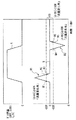
ここで、図5を参照して、従来の膜式流量計を搭載したガスメータにおける警告動作の実行に係る判定手順について説明する。図5は、ガスメータによって検出されるガス流量変化の一例を表すものであり、図中における「横軸」は時間T(秒)を表し、「縦軸」はガス流量Q(瞬時流量;L(リットル)/h(時間))を表している。図5では、例えば、時間T1よりも以前からガス器具Uが稼働している状態において時間T2の経過後からガス器具Vが稼働し、時間T4において双方のガス器具が停止した場合を示している。膜式流量計を搭載したガスメータは、例えば、瞬間的なガス流量(瞬時流量)を把握することができないため、ガスの消費に応じて入力される流量パルスを所定の時間間隔(約30秒間)ごとにカウントし、この流量パルスに対して所定のパルスレートを乗ずることによりガス流量の演算を行っている。すなわち、例えば、時間T2に到達した時点において、時間T1〜T2間に消費されたガス流量Q1が演算され、同様にガス流量Q2,Q3が演算される。ここで、流量パルスのカウント間隔を「約30秒間」としたのは、流量パルスのカウントは、必ずしも30秒間ごとに行われるものとは限らず、30秒を経過したのちに次の流量パルスを検出する時点まで行われるためである。
【0005】
まず、ガスメータは、時間T3において、最も新しく測定したガス流量Q2とその直前に測定したガス流量Q1との流量差(すなわちガス流量の増加量;Q2−Q1)を演算し、この流量差の絶対値(|Q2−Q1|)がガス流量Q1の所定倍(例えば0.03倍;0.03Q1)よりも大きいかどうかを判定する。このとき、ガスメータは、流量差の絶対値がガス流量Q1の0.03倍よりも大きい場合(|Q2−Q1|>0.03Q1)にはガスの消費状態に変化が生じた(1のガス器具Vが新たに稼働した)ものと判断し、一方、流量差の絶対値がガス流量Q1の0.03倍以下であった場合(|Q2−Q1|≦0.03Q1)にはガスの消費状態に変化が生じなかった(新たに稼働したガス器具は存在しない)ものと判断する。ガスの消費状態に変化が生じたものと判断した場合には、ガスメータは、時間T4において、最も新しく測定したガス流量Q3とその2つ前(約60秒前)に測定したガス流量Q1との流量差(Q3−Q1)を演算し、この流量差を新たに稼働したガス器具Vの個別流量として登録する。続いて、ガスメータは、登録した個別流量が所定の流量(安全流量)以上であるかどうかを判定する。個別流量が安全流量である場合には、ガスメータは、通常のガスの利用状態では生じないような過大なガスの消費状態を検知したものと判断し、一連の警告動作を実行する。なお、ガスメータは、所定の流量以下のガスの消費状態を検出した時点(時間T5)において、全てのガス器具が停止したものと判断する。
【0006】
【発明が解決しようとする課題】
ところで、ガスを利用する消費者の利便性を考慮するならば、警告動作の実行に係る判定の信頼性を高め、警告動作の誤動作を回避する必要がある。しかしながら、従来のガスメータでは、以下のような理由により、警告動作の実行に係る判定の信頼性が十分なものではないという問題があった。すなわち、図6に示したように、例えば、時間T2〜T3間において、ガス器具Vの稼働後、さらに他のガス器具Wが稼働した場合には、ガスメータは、2台のガス器具(ガス器具V,ガス器具W)が稼働しているにもかかわらず、時間T4において、あたかも流量差Q5−Q1に相当する個別流量を有する1台のガス器具が稼働しているものと判断してしまう。このときの個別流量は、2台のガス器具の個別流量の総和となるため、比較的大きな流量となる。このような場合には、個別流量が安全流量以上となり、2台のガス器具が正常に稼働しているにもかからわず警告動作が誤って実行される可能性が高くなる。
【0007】
本発明はかかる問題点に鑑みてなされたもので、その目的は、警告動作の実行に係る判定の信頼性を向上させることが可能なガスメータおよびガス供給に係る異常判定方法を提供することにある。
【0008】
【課題を解決するための手段】
本発明のガスメータは、1または2以上のガス燃焼機器によって消費される燃料ガスの流量を所定の時間間隔ごとに測定する流量測定手段と、この流量測定手段により測定された燃料ガスの流量のうちの最も新しく測定された対象流量とこれよりも以前に測定された比較流量との流量差を演算する流量差演算手段と、この流量差演算手段によって演算された流量差の絶対値を基準流量と比較することにより燃料ガスの消費状態に変化が生じたかどうかを判定する流量差判定手段と、この流量差判定手段による判断結果を監視し、燃料ガスの消費状態に変化が生じなかったものとする判断から変化が生じたものとする判断へ移行する第1の判断移行状態を検出したのち、燃料ガスの消費状態に変化が生じたものとする判断から変化が生じなかったものとする判断へ移行する第2の判断移行状態を検出したときに、1または2以上のガス燃焼機器のうちの1のガス燃焼機器の稼働状態が変化したものと判断する第1の稼動判断手段と、この第1の稼働判定手段により1のガス燃焼機器の稼働状態が変化したものと判断されたときに、この判断に至る流量差の変化過程において流量差が正の領域内において変化している場合には1のガス燃焼機器が稼働したものと判断し、一方、流量差が負の領域内において変化している場合には1のガス燃焼機器が停止したものと判断する第2の稼働判断手段と、この第2の稼働判断手段段によって1のガス燃焼機器の稼働が判断されたときに、最も新しく検出された判断移行状態に対応する燃料ガスの流量とこれよりも以前に検出された判断移行状態に対応する燃料ガスの流量との差として稼働している1のガス燃焼機器の個別流量を演算する個別流量演算手段と、この個別流量演算手段によって演算された個別流量が安全流量以上であるかどうかを判定する安全判定手段と、この安全判定手段によって個別流量が安全流量以上であると判定されたときに1または2以上のガス燃焼機器に対する燃料ガスの供給を遮断する遮断手段とを備えるようにしたものである。
【0009】
本発明のガスメータでは、流量測定手段により、1または2以上のガス燃焼機器によって消費される燃料ガスの瞬時流量が所定の時間間隔ごとに測定され、流量差演算手段により、燃料ガスの流量のうちの最も新しく測定された対象流量とこれよりも以前に測定された比較流量との流量差が演算され、流量差判定手段により、流量差の絶対値が基準流量と比較されることにより燃料ガスの消費状態に変化が生じたかどうか判定される。この流量差判定手段による判断結果は第1の稼動判断手段により監視され、燃料ガスの消費状態に変化が生じなかったものとする判断から変化が生じたものとする判断へ移行する第1の判断移行状態が検出されたのち、燃料ガスの消費状態に変化が生じたものとする判断から変化が生じなかったものとする判断へ移行する第2の判断移行状態が検出されたときに、1または2以上のガス燃焼機器のうちの1のガス燃焼機器の稼働状態が変化したものと判断される。1のガス燃焼機器の稼働状態が変化したものと判断されたときには、第2の稼働判断手段により、この判断に至る流量差の変化過程において流量差が正の領域内において変化している場合には1のガス燃焼機器が稼働したものと判断され、一方、流量差が負の領域内において変化している場合には1のガス燃焼機器が停止したものと判断される。1のガス燃焼機器の稼働が判断されたときには、個別流量演算手段により、最も新しく検出された第2の判断移行状態に対応する燃料ガスの流量とこれよりも以前に検出された他の第2の判断移行状態に対応する燃料ガスの流量との差として稼働している1のガス燃焼機器の個別流量が演算され、安全判定手段により、個別流量が安全流量以上であるかどうかが判定される。個別流量が安全流量以上であると判定されたときには、遮断手段により、1または2以上のガス燃焼機器に対する燃料ガスの供給が遮断される。
【0010】
本発明のガスメータでは、流量差判定手段が、流量差演算手段によって演算された流量差の絶対値が基準流量以上であったときに燃料ガスの消費状態に変化が生じたものと判定し、一方、流量差の絶対値が基準流量より小さいときに燃料ガスの消費状態に変化が生じなかったものと判定するようにしてもよい。
【0011】
また、本発明のガスメータでは、基準流量が比較流量の所定倍に相当するものであるようにしてもよい。
【0012】
また、本発明のガスメータでは、流量差演算手段が、対象流量を用いて所定の演算処理を行ったのち、演算処理後の対象流量と比較流量との流量差を演算するものであるようにしてもよい。
【0013】
また、本発明のガスメータでは、流量差演算手段が、演算した流量差を用いて所定の演算処理を行うものであるようにしてもよい。
【0014】
また、本発明のガスメータでは、第1の稼動判断手段が、第2の判断移行状態を検出したのち、燃料ガスの消費状態に変化が生じなかったものとする判断を所定の回数に渡って連続して検出したときに1のガス燃焼機器の稼働状態が変化したものと判断するものであるようにし、個別流量演算手段が、流量差判定手段による燃料ガスの消費状態に変化が生じなかったものとする判断タイミングごとに測定された燃料ガスの流量の平均値を用いて個別流量を演算するものであるようにしてもよい。
【0015】
また、本発明のガスメータでは、第1の稼動判断手段が、最も新しく検出された第2の判断移行状態の検出タイミングが、これよりも以前に検出された他の第2の判断移行状態の検出タイミングから所定の時間以内であった場合には、最も新しく検出された第2の判断移行状態に関する認識を消去するものであるようにしてもよい。
【0016】
本発明のガス供給に係る異常判定方法は、1または2以上のガス燃焼機器によって消費される燃料ガスの流量を所定の時間間隔ごとに測定する第1のステップと、燃料ガスの流量のうちの最も新しく測定した対象流量とこれよりも以前に測定した比較流量との流量差を演算する第2のステップと、流量差の絶対値を基準流量と比較することにより燃料ガスの消費状態に変化が生じたかどうかを判定する第3のステップと、燃料ガスの消費状態に変化が生じなかったものとする判断から変化が生じたものとする判断へ移行する第1の判断移行状態を検出したのち、燃料ガスの消費状態に変化が生じたものとする判断から変化が生じなかったものとする判断へ移行する第2の判断移行状態を検出したときに、1または2以上のガス燃焼機器のうちの1のガス燃焼機器の稼働状態が変化したものと判断する第4のステップと、1のガス燃焼機器の稼働状態が変化したものと判断したときに、この判断に至る流量差の変化過程において、流量差が正の領域内において変化している場合には1のガス燃焼機器が稼働したものと判断し、一方、流量差が負の領域内において変化している場合には1のガス燃焼機器が停止したものと判断する第5のステップと、1のガス燃焼機器の稼働を判断したときに、最も新しく検出した第2の判断移行状態に対応する燃料ガスの流量とこれよりも以前に検出した他の第2の判断移行状態に対応する燃料ガスの流量との差として稼働している1のガス燃焼機器の個別流量を演算する第6のステップと、この個別流量が安全流量以上であるかどうかを判定する第7のステップと、個別流量が安全流量以上であると判定したときに1または2以上のガス燃焼機器に対する燃料ガスの供給を遮断する第8のステップとを含むようにしたものである。
【0017】
本発明のガス供給に係る異常判定方法では、第1のステップにおいて、1または2以上のガス燃焼機器によって消費される燃料ガスの流量が所定の時間間隔ごとに測定され、第2のステップにおいて、燃料ガスの流量のうちの最も新しく測定された対象流量とこれよりも以前に測定された比較流量との流量差が演算され、第3のステップにおいて、流量差の絶対値が基準流量と比較されることにより燃料ガスの消費状態に変化が生じたかどうかが判定される。続いて、第4のステップにおいて、燃料ガスの消費状態に変化が生じなかったものとする判断から変化が生じたものとする判断へ移行する第1の判断移行状態が検出されたのち、燃料ガスの消費状態に変化が生じたものとする判断から変化が生じなかったものとする判断へ移行する第2の判断移行状態が検出されたときに、1または2以上のガス燃焼機器のうちの1のガス燃焼機器の稼働状態が変化したものと判断される。続いて、第5のステップにおいて、1のガス燃焼機器の稼働状態が変化したものと判断されたときに、この判断に至る流量差の変化過程において、流量差が正の領域内において変化している場合には1のガス燃焼機器が稼働したものと判断され、一方、流量差が負の領域内において変化している場合には1のガス燃焼機器が停止したものと判断される。続いて、第6のステップにおいて、1のガス燃焼機器の稼働が判断されたときに、最も新しく検出された第2の判断移行状態に対応する燃料ガスの流量とこれよりも以前に検出された他の第2の判断移行状態に対応する燃料ガスの流量との差として稼働している1のガス燃焼機器の個別流量が演算され、第7のステップにおいて、この個別流量が安全流量以上であるかどうかが判定される。最後に、第8のステップにおいて、個別流量が安全流量以上であると判定されたときに1または2以上のガス燃焼機器に対する燃料ガスの供給が遮断される。
【0018】
本発明によるガス供給に係る異常判定方法では、第3のステップにおいて、流量差の絶対値が基準流量以上であったときに燃料ガスの消費状態に変化が生じたものと判定し、一方、流量差の絶対値が基準流量より小さいときに燃料ガスの消費状態に変化が生じなかったものと判定するようにしてもよい。
【0019】
また、本発明のガス供給に係る異常判定方法では、比較流量の所定倍に相当するように基準流量を設定するようにしてもよい。
【0020】
また、本発明のガス供給に係る異常判定方法では、第2のステップにおいて、対象流量を用いて所定の演算処理を行ったのち、演算処理後の対象流量と比較流量との流量差を演算するようにしてもよい。
【0021】
また、本発明のガス供給に係る異常判定方法では、さらに、第2のステップと第3のステップとの間に、演算した流量差を用いて所定の演算処理を行う第10のステップを含むようにしてもよい。
【0022】
また、本発明のガス供給に係る異常判定方法では、第4のステップにおいて、第2の判断移行状態を検出したのち、燃料ガスの消費状態に変化が生じなかったものとする判断を所定の回数に渡って連続して検出したときに1のガス燃焼機器の稼働状態が変化したものと判断し、第6のステップにおいて、第3のステップにおける燃料ガスの消費状態に変化が生じなかったものとする判断タイミングごとに取得された燃料ガスの流量の平均値を用いて個別流量を演算するようにしてもよい。
【0023】
また、本発明のガス供給に係る異常判定方法では、第4のステップにおいて、最も新しく検出した第2の判断移行状態の検出タイミングが、これよりも以前に検出した他の第2の判断移行状態の検出タイミングから所定の時間以内であった場合には、最も新しく検出した第2の判断移行状態に関する認識を消去するようにしてもよい。
【0024】
【発明の実施の形態】
以下、本発明の実施の形態について、図面を参照して詳細に説明する。
【0025】
図1は、本発明の一実施の形態に係るガスメータ10の要部の概略構成を表すものである。なお、本実施の形態に係る「ガス供給に係る異常判定方法」は、このガスメータ10によって具現化されるので、以下、併せて説明する。
【0026】
ガスメータ10は、筐体の内部に、配管中を流れるガスGの流量を測定するための計量部11と、ガスメータ10全体の動作を制御するためのCPU(Central Proccessing Unit;中央演算処理装置)12と、各種情報を格納するためのRAM(Random Access Memory)13と、時間計測を行うためのクロック14と、CPU12等に電力供給を行うためのリチウムバッテリ15と、ガスメータ10よりも下流側へのガスGの供給状態を切り替えるための遮断弁16とを備えている。また、筐体の外側の表面には、ガスメータ10に関する各種情報を表示するための表示部17が設けられている。なお、図示しないが、このガスメータには、配管を介して1または2以上のガス器具(例えば、ガスレンジ,ガス湯沸し器,ガス暖房器等)が設置されているものとする。ここで、計量部11が本発明における「流量測定手段」の一具体例に対応し、遮断弁16が本発明における「遮断手段」の一具体例に対応する。
【0027】
計量部11は、例えば、フルイディック素子や熱式のフローセンサよりなるものであり、配管中を流れるガスGの流量に応じて、CPU12に対して流量信号を出力するようになっている。このような構成を有する計量部11を用いることにより、膜式流量計などの場合とは異なり、ガスGの瞬時流量QSを測定することが可能となる。
【0028】
CPU12は、主に、例えば、クロック14から出力されるクロック信号に基づいて、所定の時間間隔(例えば1秒)ごとに、計量部11から出力される流量信号を取り込み、この流量信号に基づいてガスGの瞬時流量QSを演算するようになっている。また、CPU12は、例えば、所定の時間間隔(例えば1時間)ごとに瞬時流量QSを積算してガスGの積算流量QKを演算するようになっている。CPU12は、取得した一連の流量データ(QS,QK)を表示部17に対して出力すると共にRAM13に随時格納する。
【0029】
このCPU12は、特に、ガスGの使用にともなう消費者の安全を確保することを目的とした以下のような保安機能を有している。すなわち、CPU12は、例えば、まず、ガスGの瞬時流量QSを演算したのち、最も新しく演算した瞬時流量QSを含めた過去10回分の瞬時流量の平均値として平均流量QSRを演算する(移動平均演算処理)。この移動平均演算処理は、例えば、CPU12による瞬時流量QSの演算開始後、10個の流量データ(10個の瞬時流量QS)を取得した時点から開始される。もちろん、この移動平均演算処理は、瞬時流量QSの演算タイミングごとに繰り返し行われる。
【0030】
続いて、CPU12は、最も新しく演算した平均流量QSR(対象流量)と、これよりも以前(例えば10秒前)に演算した平均流量QSR(比較流量)との流量差ΔQSを演算する。ここで、図2は、ガスGの平均流量QSRの変化(A)および流量差ΔQSの変化(B)の一例を表すものであり、両者の相関を説明するためのものである。図2において、「横軸」は時間T(秒)を表し、「縦軸」は平均流量QSRまたは流量差ΔQS(L/h)を表している。いずれのガス器具も稼働していない状態において1のガス器具Xが稼働・停止する場合には、平均流量QSRは、ガス器具Xの稼働に応じて増加してほぼ一定となったのち、ガス器具Xの停止に応じて減少する。このとき、流量差ΔQSは、平均流量QSRの増加に応じて増加したのち、平均流量QSRが一定になると減少する。また、稼働していたガス器具Xが停止する場合には、流量差ΔQSは、平均流量QSRの減少に応じて減少したのち増加する。ここで、CPU12が、本発明における「流量差演算手段」の一具体例に対応する。
【0031】
続いて、CPU12は、例えば、演算した流量差ΔQSを用いて所定の平均化演算処理を行う。この平均化演算処理は、例えば、以下のような演算式を用いて行われる。
【0032】
ΔQS=1/4ΔQS1+3/4ΔQS2
【0033】
上記の式中において、「ΔQS」は平均化演算処理後の流量差、「ΔQS1」は最も新しく演算した流量差、「ΔQS2」は「ΔQS」よりも1つ前(例えば1秒前)に平均化演算処理を行った流量差をそれぞれ表している。
【0034】
続いて、CPU12は、例えば、平均化演算処理後の流量差ΔQSを用いて所定の切り捨て演算処理を行う。この切り捨て演算処理としては、例えば、流量差ΔQSの「1の桁」を切り捨てるようにする。具体的には、例えば、平均化演算処理前の流量差ΔQSが「96L/h」である場合には、これを「90L/h」とする。ただし、切り捨て演算処理を適用する「桁」は必ずしも「1の桁」に限らず、例えば、「1の桁」以外の桁(例えば、「10の桁」)に適用してもよいし、または複数の桁(例えば、「1の桁」および「10の桁」)に適用するようにしてもよい。もちろん、上記の平均化演算処理および切り捨て演算処理は、流量差ΔQSの演算タイミングごとに繰り返し行われる。
【0035】
続いて、CPU12は、切り捨て演算処理後の流量差ΔQSの絶対値(|ΔQS|)を基準流量QSKと比較することによりガスGの消費状態に変化が生じたかどうかを判定する。具体的には、CPU12は、例えば、切り捨て演算処理後の流量差ΔQSの絶対値(|ΔQS|)が基準流量QSK以上であるかどうかを判定する。この基準流量ΔQSKは、ガスGの消費状態の変化を検出するための検出基準となるものであり、例えば、予めガス事業者等により設定され、RAM13に格納されている。基準流量ΔQSKとしては、例えば、所定の流量(例えば100L/h)を固定して登録するようにしてもよいし、または流量差ΔQSの演算タイミングごとに平均流量QSR(比較流量)の所定倍(例えば0.03倍)の流量が演算されるようにしてもよい。このとき、CPU12は、流量差ΔQSの絶対値が基準流量QSK以上である場合(|ΔQS|≧QSK)には、ガスGの消費状態に変化が生じたもの(流量変化有)と判断し、一方、流量差ΔQSの絶対値が基準流量より小さい場合(|ΔQS|<QSK)にはガスGの消費状態に変化が生じなかったもの(流量変化無)と判断する。ここで、CPU12が、本発明における「流量差判定手段」,「消費状態判断」の一具体例に対応する。
【0036】
ここで、再び図2を参照して、流量差ΔQSの変化とガスGの消費状態の変化(ガス器具の稼働状態の変化)との相関について説明する。図2に示したように、上記した「流量差ΔQSの絶対値(|ΔQS|)が基準流量QSK以上であるかどうか」の判定結果として、流量差ΔQSの変化パターン中の各領域について、以下のように、CPU12によりガスGの消費状態の変化(「流量変化有」または「流量変化無」)が判断されることとなる。すなわち、流量差ΔQSの変化パターンのうち、流量差ΔQSが+QSR以上(ΔQS≧+QSR)の領域R1および流量差ΔQSが−QSR以下(ΔQS≦−QSR)の領域R2では、流量差ΔQSの絶対値が基準流量QSK以上(|ΔQS|≧QSK)となるため、これらの領域R1および領域R2は「流量変化有」と判断される。一方、流量差ΔQSが−QSRより大きく+QSRよりも小さい範囲内(−QSR<ΔQS<+QSR)である領域R3では、流量差ΔQSの絶対値が基準流量QSKよりも小さく(|ΔQS|<QSK)なるため、この領域R3は「流量変化無」と判断される。図中の点M1は、「流量変化無」から「流量変化有」へ判断内容が移行した状態に相当し、点M2は、点M1以降における最後の「流量変化有」の判断状態に対応し、点M3は、「流量変化有」から「流量変化無」へ判断内容が移行した状態に相当する。流量差ΔQSは点M1〜点M2間において正の領域内で変化することとなり、このときの流量差ΔQSの変化はガス器具の「稼働」に対応するものである。また、図中の点M4,M5,M6は、上記の点M1,M2,M3にそれぞれ対応するものである。流量差ΔQSは点M4〜点M5間において負の領域内で変化することとなり、このときの流量差ΔQSの変化はガス器具の「停止」に対応するものである。ガスGの消費状態の変化に関する判断(「流量変化有」または「流量変化無」)を監視することにより、ガス器具の稼働状態(稼働,停止)を判断することが可能となる。
【0037】
続いて、CPU12は、ガスGの消費状態の変化に関する判断結果(「流量変化有」または「流量変化無」)を監視し、「流量変化無」から「流量変化有」へ判断内容が移行する「第1の判断移行状態」を検出する。そして、CPU12は、「第1の判断移行状態」を検出したのち、ガスGの消費状態の変化に関する判断結果を継続して監視し、「流量変化有」から「流量変化無」へ判断内容が移行する「第2の判断移行状態」を検出する。「第1の判断移行状態」〜「第2の判断移行状態」間では、例えば、「流量変化有」の判断が連続して検出される。「第1の判断移行状態」を検出したのち「第2の判断移行状態」を検出した場合には、CPU12は、1のガス器具の稼働状態に変化が生じたものと判断する。ここで、CPU12が、本発明における「第1の稼動判断手段」の一具体例に対応する。
【0038】
続いて、CPU12は、例えば、最も新しく検出した「第2の判断移行状態」よりも以前に他の「第2の判断移行状態」を検出していなかったかどうかを確認する。このとき、他の「第2の判断移行状態」を検出していた場合において、例えば、他の「第2の判断移行状態」の検出タイミングから最も新しく検出した「第2の判断移行状態」の検出タイミングまでの時間(検出間隔TH)が所定の時間(検出許容時間TY;例えば5秒)以下であった場合(TH≦TY)には、CPU12は、最も新しく検出した「第2の判断移行状態」がガスGの利用以外の要因(例えばガスGの脈動等)によるものであると判断し、このときの「第2の判断移行状態」に関する認識を消去する。なお、検出間隔THが検出許容時間TYより大きい場合(TH>TY)ときには、CPU12は、最も新しく検出した「第2の判断移行状態」がガス器具の稼働または停止に応じて発生したものであると判断する。このような「第2の判断移行状態」の検出間隔THに関する判定は、「第2の判断移行状態」の検出タイミングごとに行われる。
【0039】
続いて、消去対象外の「第2の判断移行状態」を検出した場合には、CPU12は、「第1の判断移行状態」〜「第2の判断移行状態」間における流量差ΔQSの変化過程において、流量差ΔQSが正の領域内で変化していたか、あるいは負の領域内で変化していたかを判定する。このとき、CPU12は、流量差ΔQSが正の領域内で変化していた場合には1のガス器具Xが新たに稼働したものと判断し、一方、流量差ΔQSが負の領域内で変化していた場合には1のガス器具Xが停止したものと判断する。ここで、CPU12が、本発明における「第2の稼働判断手段」の一具体例に対応する。
【0040】
続いて、CPU12は、「第2の判断移行状態」に対応するガスGの平均流量QSRを流量増加量、すなわちガス器具Xの個別流量QBXとして登録し、RAM13に格納する。
【0041】
続いて、CPU12は、個別流量QBXが安全流量QZ以上であるかどうかを判定する。この「安全流量QZ」は、例えば、消費者宅内に設置されている複数のガス器具のうち、ガス消費量の大きい任意の2つのガス器具が同時に稼働した場合におけるガスGの瞬時流量QSの増加量よりも大きい範囲の流量となるようにガス事業者等により設定され、予めRAM13に格納されている。個別流量QBXが安全流量QZ以上である場合(QBX≧QZ)には、CPU12は、通常のガスGの利用状態では生じないような過大なガスGの消費状態を検知したものと判断して警告動作を実行する。このとき、CPU12は、警告動作として、例えば、遮断弁16に対して弁駆動信号Sを出力し、遮断弁16を駆動させることによりガス器具に対するガスGの供給を遮断する(個別流量オーバー遮断)。なお、個別流量QBXが安全流量QZより小さい場合(QBX<QZ)には、CPU12は、正常なガスGの利用状態を検知したものと判断する。ここで、CPU12が、本発明における「安全判定手段」の一具体例に対応する。
【0042】
なお、上記ではいずれのガス器具も稼働していない状態において1のガス器具Xが稼働する場合について説明したが、1のガス器具Xが先行して稼働している状態において他のガス器具Yが稼働するような場合には、CPU12は、ガス器具Yの稼働に応じて検出した「第2の判断移行状態」に対応するガスGの平均流量QSRと、ガス器具Xの稼働に応じて検出した「第2の判断移行状態」に対応するガスGの平均流量QSR(すなわち、ガス器具Xの稼働時において登録済みの個別流量QBX)との差としてガス器具Yの個別流量QBY(=QSR−QBY)を演算し、登録する。もちろん、3以上のガス器具が順次稼働する場合においても同様に各ガス器具の稼働が随時認識され、それらの個別流量が順次演算される。ここで、CPU12が、本発明における「個別流量演算手段」の一具体例に対応する。
【0043】
上記した「瞬時流量QSの測定タイミング(例えば1秒)」、「平均流量QSRを演算する際に用いる瞬時流量QSの個数(移動平均幅;例えば10個)」、「流量差ΔQSを演算する際に用いる瞬時流量QS(比較流量)の選択タイミング(例えば10秒前の瞬時流量QS)」、「切り捨て演算処理における切り捨て対象桁(例えば1の桁)」および「検出許容時間TY(例えば5秒)」等の各パラメータ値は自由に変更可能になっている。
【0044】
なお、CPU12は、上記した個別流量オーバー遮断機構以外の各種の遮断機構も備えている。具体的には、例えば、ガスGの消費量(例えば、個別流量または合計流量)ごとにガスGを継続して消費可能な時間(継続時間)が予め登録されており、ガスGの消費時間が継続時間に到達したときにガスGの供給を遮断するもの(継続時間オーバー遮断)や、ガスGの合計流量が予め設定された流量(安全最大流量)に到達したときにガスGの供給を遮断するもの(合計流量オーバー遮断)などである。
【0045】
引き続き、図1を参照して、ガスメータ10の構成例について説明する。遮断弁16は、CPU12から出力される弁駆動信号Sに応じて駆動し、ガス器具に対するガスGの供給を遮断するようになっている。
【0046】
表示部17は、例えば表示パネル等よりなるものであり、ガスGの流量データ(QS,QK)や遮断弁16の駆動状況等の情報を表示するようになっている。消費者またはガス事業者等は、表示部17を目視にて確認することにより、ガスGの利用状況を把握することができる。
【0047】
次に、図1〜図4を参照して、本実施の形態に係るガスメータ10の動作について説明する。ここで、図3および図4は、ガスメータ10の動作を説明するための流れ図である。以下では、主に、例えば、1のガス器具Xが先行して稼働している状態(ガス器具Xの個別流量QBXが登録済み)において、他のガス器具Yが稼働する場合における保安機能(個別流量オーバー遮断機構)に係るCPU12の動作について説明する。
【0048】
このガスメータ10では、まず、計量部11を作動させ、所定の時間間隔(例えば1秒)ごとにガスGの瞬時流量QSを演算する(図3;ステップS101)。続いて、例えば、最も新しく演算した瞬時流量QSを含めた過去10回分の瞬時流量の平均値として平均流量QSRを演算する(移動平均演算処理,図3;ステップS102)。続いて、最も新しく演算した平均流量QSR(対象流量)と、これよりも以前(例えば10秒前)に演算した平均流量QSR(比較流量)との流量差ΔQSを演算する(図3;ステップS103)。
【0049】
続いて、演算した流量差ΔQSを用いて所定の平均化演算処理を施す(図3;ステップS104)。この平均化演算処理としては、例えば、平均化演算処理後の流量差を「ΔQS」,最も新しく演算した流量差を「ΔQS1」,「ΔQS」よりも1つ前(例えば1秒前)に平均化演算処理を行った流量差を「ΔQS2」とした場合、「ΔQS=1/4ΔQS1+3/4ΔQS2」よりなる演算を行う。続いて、平均化演算後の流量差ΔQSを用いて所定の切り捨て演算処理を行う(図3;ステップS105)。この切り捨て演算処理としては、例えば、流量差ΔQSの「1の桁」を切り捨てるようにする。
【0050】
続いて、切り捨て演算処理後の流量差ΔQSの絶対値(|ΔQS|)が基準流量QSK以上であるかどうかを判定する(図3;ステップS106)。このとき、流量差ΔQSの絶対値が基準流量QSK以上である場合(|ΔQSR|≧QSK,図3;ステップS106Y)には、ガスGの消費状態に変化が生じたもの(流量変化有)と判断し、「流量変化無」から「流量変化有」へ判断内容が変化する「第1の判断以降状態」を検出する(図3;ステップS107)。続いて、CPU12は、「流量変化有」から「流量変化無」へ判断内容が変化する「第2の判断以降状態」を検出する(図3;ステップS108)。なお、流量差ΔQSの絶対値が基準流量QSKより小さい場合(|ΔQS|<QSK,図3;ステップS106N)には、ガスGの消費状態に変化が生じなかったものと判断し、瞬時流量QSの測定(ステップS101)に回帰する。
【0051】
続いて、最も新しく検出した「第2の判断以降状態」よりも以前に他の「第2の判断以降状態」を検出していなかったかどうかを確認する(図4;ステップS109)。このとき、他の「第2の判断以降状態」を検出していた場合(図4;ステップS109Y)には、他の「第2の判断以降状態」の検出タイミングから最も新しく検出した「第2の判断以降状態」の検出タイミングまでの時間(検出間隔TH)が所定の時間(検出許容時間TY;例えば5秒)以下であるかどうかを判定する(図4;ステップS110)。検出間隔THが検出許容時間TH以下であった場合(TH≦TY,図4;ステップS110Y)には、最も新しく検出した「第2の判断以降状態」がガスGの利用以外の要因(例えばガスGの脈動等)によるものであると判断し、このときの「第2の判断以降状態」に関する認識を消去する。なお、検出間隔THが検出許容時間TYより大きい場合(TH>TY,図4;ステップS110N)には、検出した「第2の判断以降状態」がガス器具の稼働または停止に応じて発生したものであると判断する。
【0052】
続いて、「第1の判断移行状態」〜「第2の判断移行状態」における流量差ΔQSの変化過程において、流量差ΔQSが正の領域内で変化していたかどうかを判定する(図4;ステップS111)。なお、上記した他の「第2の判断移行状態」の検出確認(ステップS109)」時において、最も新しく検出した「第2の判断移行状態」よりも以前に他の「第2の判断移行状態」を検出していなかった場合(図4;ステップS109N)には、上記した「検出間隔THに関する判定(ステップS110)」を省略して「流量差ΔQSの変化領域の確認に関する判定(ステップS111)」に移行する。このとき、流量差ΔQSが正の領域内で変化していた場合(図4;ステップS111Y)には、1のガス器具Yが新たに稼働したものと判断し、ガス器具Yの稼働に応じて検出された「第2の判断移行状態」に対応する平均流量QSRと、ガス器具Xの稼働に応じて検出された「第2の判断移行状態」に対応する平均流量QSR(すなわち、ガス器具Xの稼働時において登録済みの個別流量QBX)との差としてガス器具Yの個別流量QBY(=QSR−QBX)を演算する(図4;ステップS112)。この個別流量QBYは、新たなガスGの消費量の増加量として登録され、RAM13に格納される。なお、流量差ΔQSが正の領域内で変化していなかった場合(流量差ΔQSが負の領域内で変化していた場合,図4;ステップS111N)には、先行して稼働していたガス器具Xが停止したものと判断し、登録されていたガス器具Xの個別流量QBXを消去する。
【0053】
続いて、演算した個別流量QBYが安全流量QZ以上であるかどうかを判定する(図4;ステップS113)。このとき、個別流量QBYが安全流量QZ以上である場合(QBY≧QZ,図4;ステップS113Y)には、通常のガスGの利用状態では生じないような過大なガスGの消費状態を検知したものと判断し、遮断弁16に対して弁駆動信号Sを出力する(図4;ステップS114)。これにより、遮断弁16が駆動し、ガス器具に対するガスGの供給が遮断される。なお、個別流量QBYが安全流量QZより小さい場合(QBY<QZ,図4;ステップS113N)には、正常なガスGの利用状態を検知したものと判断し、瞬時流量QSの測定(図3;ステップS101)に回帰する。
【0054】
以上説明したように、本実施の形態のガスメータ10およびガス供給に係る異常判定方法では、ガスGの消費状態の変化(「流量変化有」または「流量変化無」)を監視することにより「第1の判断移行状態」および「第2の判断移行状態」を順次検出したときに1のガス器具の稼働状態が変化したものと判断すると共に、特に、「第1の判断移行状態」〜「第2の判断移行状態」間において流量差ΔQSが正の領域内で変化したときに1のガス器具が新たに稼働したものと判断するようにしている。このような場合には、連続して稼働した複数のガス器具によるガスGの消費状態を1台のガス器具によるガスGの消費状態と誤判断してしまう従来の場合とは異なり、各ガス器具の稼働が随時的確に認識されるため、各ガス器具の個別流量が正確に演算され、警告動作が適正に実行される。したがって、警告動作の実行に係る判定の信頼性を向上させることができる。これにより、ガスGを利用する消費者の利便性が向上することとなる。
【0055】
また、本実施の形態では、以下のような理由により、稼働したガス器具の個別流量を演算するまでに要する時間を短縮することができる。すなわち、従来のガスメータ(図5参照)では、膜式流量計の構造的な制約により約30秒ごとにガスGの流量測定が行われるため、ガス器具Vの稼働にともないガス流量が増加してから時間T4においてガス器具Vの個別流量が演算されるまでに約60秒程度かかる。これに対して、本実施の形態(図2参照)では、ガス器具Xの稼働にともないガス流量(平均流量QSR)が増加してからガス器具Xの個別流量QBXが演算されるまで(点M3まで)に要する時間は、30秒以下である。
【0056】
また、本実施の形態では、ガスGの瞬時流量QS(対象流量)を用いて移動平均演算処理を行うことにより平均流量QSRを演算したのち、この平均流量QSRを用いて流量差ΔQSを演算するようにしたので、ガスGの脈動等に起因する平均流量QSRの変動が抑制される。このため、流量差ΔQSの変動が抑制され、ガス器具の稼働状態を正確に判断することができる。なお、上記の効果は、流量差ΔQSを用いて平均化演算処理および切り捨て演算処理を行うことによっても同様に得られる。
【0057】
また、本実施の形態では、「第2の判断移行状態」の検出タイミングごとに検出間隔THが検出許容時間TY以下であるかどうかの判定を行い、検出間隔THが検出許容時間TY以下であった場合に「第2の判断移行状態」に関する認識をを消去するようにしたので、ガスGの脈動等に起因して流量差ΔQSが変動したとしても、このときの流量差ΔQSの変動を警告動作の実行判定対象から除外することができる。
【0058】
なお、本実施の形態では、ガスGの瞬時流量QSを測定したのち、移動平均演算処理を行うようにしたが、必ずしもこれに限られるものではなく、例えば、移動平均演算処理を行わずに、瞬時流量QSをそのまま用いて流量差ΔQSの演算を行うようにしてもよい。ただし、ガスGの脈動等に起因する流量差ΔQSの変動を抑制したいならば、移動平均演算処理を行うようにするのが好ましい。
【0059】
また、本実施の形態では、流量差ΔQSを演算したのち、この流量差ΔQSを用いて平均化演算処理および切り捨て演算処理の双方を行うようにしたが、必ずしもこれに限られるものではない。例えば、平均化演算処理または切り捨て演算処理のいずれか一方のみを行うようにしてよいし、またはいずれの演算処理も行わないようにしてもよい。ただし、ガスGの脈動等に起因する流量差ΔQSの変動を抑制したいならば、平均化演算処理および切り捨て演算処理の双方を行うようにするのが好ましい。なお、演算処理の実行順は自由であり、切り捨て演算処理を行ったのちに平均化演算処理を行うようにしてもよい。さらに、流量差ΔQSを演算したのち、この流量差ΔQSを用いて移動平均演算処理を行うようにしてもよい。
【0060】
また、本実施の形態では、「第1の判断移行状態」を検出したのち「第2の判断移行状態」を検出したときに、1のガス器具の稼働状態に変化が生じたものと判断するようにしたが、必ずしもこれに限られるものではない。例えば、「第2の判断移行状態」を検出したのち、ガスGの消費状態に変化が生じなかったものとする判断(流量変化無)を所定の回数(例えば2回)に渡って連続して検出したときに、1のガス器具の稼働状態に変化が生じたものと判断するようにしてもよい。これにより、ガスGの脈動等に起因して流量差ΔQSが変動したとしても、このときの流量差ΔQSの変動を警告動作の実行判定対象から除外することができると共に、ガス器具の稼働状態をより正確に判断することができる。なお、上記のような場合には、ガスGの消費状態に変化が生じなかったものとする判断タイミング(「流量変化無」とする判断タイミング)ごとに測定されたガス流量(平均流量QSR)の平均値を用いて個別流量QBYを演算するようにしてもよい。あるいは、ガス流量(平均流量QSR)を用いて複数の個別流量QBYを演算したのち、これらの複数の個別流量QBYの平均値を演算するようにしてもよい。
【0061】
また、本実施の形態では、切り捨て演算処理の替わりに切り上げ演算処理または四捨五入演算処理などを行うようにしてもよい。いずれの演算処理を行う場合においても、例えば、流量差ΔQSの「1の桁」を切り上げまたは四捨五入するようにする。具体的に、切り上げ演算処理としては、例えば、平均化演算処理前の流量差ΔQSが「92L/h」である場合には、これを「100L/h」とする。
【0062】
以上、実施の形態を挙げて本発明を説明してきたが、本発明は上記実施の形態において説明したものに限定されるものではなく、種々の変形が可能である。例えば、上記実施の形態では、ガスGの脈動等に起因する流量差ΔQSの変動を抑制することを目的として、警告動作の実行に係る一連の判定過程において、移動平均演算処理、平均化演算処理および切り捨て演算処理等を行うようにしているが、演算処理の種類は必ずしもこれらのものに限られるものではなく、上記以外の各種の演算処理を行うようにしてもよい。
【0063】
【発明の効果】
以上説明したように、請求項1ないし請求項7のいずれか1項に記載のガスメータまたは請求項8ないし請求項14のいずれか1項に記載のガス供給に係る異常判定方法によれば、流量差の絶対値と基準流量との比較判定により得られる燃料ガスの消費状態の変化に関する判断に基づき、燃料ガスの消費状態に変化が生じなかったものとする判断から変化が生じたものとする判断へ移行する第1の判断移行状態を検出したのち、燃料ガスの消費状態に変化が生じたものとする判断から変化が生じなかったものとする判断へ移行する第2の判断移行状態を検出したときに1のガス燃焼機器の稼働状態が変化したものと判断するようにしている。このような場合には、複数のガス燃焼機器が稼働する場合において各ガス燃焼機器の稼働が随時的確に認識されるため、各ガス燃焼機器の個別流量が正確に演算され、警告動作が適正に実行される。したがって、警告動作の実行に係る判定の信頼性を向上させることができる。
【0064】
特に、請求項4記載のガスメータまたは請求項11記載のガス供給に係る異常判定方法によれば、対象流量を用いて所定の演算処理を行ったのち、演算後の対象流量と比較流量との流量差を演算するようにしたので、燃料ガスの脈動等に起因する流量差のばらつきが抑制され、ガス燃焼機器の稼働状態の判断を正確に行うことができる。
【0065】
また、請求項5記載のガスメータまたは請求項12記載のガス供給に係る異常判定方法によれば、演算した流量差を用いて所定の演算処理を行うようにしたので、燃料ガスの脈動等に起因する流量差のばらつきが抑制され、ガス燃焼機器の稼働状態を正確に判断することができる。
【0066】
また、請求項6記載のガスメータまたは請求項13記載のガス供給に係る異常判定方法によれば、第2の判断移行状態を検出したのち、燃料ガスの消費状態に変化が生じなかったものとする判断を所定の回数に渡って連続して検出したときに1のガス燃焼機器の稼働状態が変化したものと判断するようにしたので、燃料ガスの脈動等に起因して流量差が変動したとしても、このときの流量差の変動を警告動作の実行判定対象から除外することができると共に、ガス燃焼機器の稼働状態をより正確に判断することができる。
【0067】
また、請求項7記載のガスメータまたは請求項14記載のガス供給に係る異常判定方法によれば、最も新しく検出した第2の判断移行状態の検出タイミングが、これよりも以前に検出した他の第2の判断移行状態の検出タイミングから所定の時間以内であった場合には、最も新しく検出した第2の判断移行状態に関する認識を消去するようにしたので、燃料ガスの脈動等に起因して発生する流量差の変動を警告動作の実行判定対象から除外することができる。
【図面の簡単な説明】
【図1】本発明の一実施の形態に係るガスメータの概略構成を表すブロック図である。
【図2】平均流量と流量差との相関を説明するための図である。
【図3】ガスメータの動作を説明するための流れ図である。
【図4】図3に続く動作を説明するための流れ図である。
【図5】従来のガスメータにおける警告動作の実行に係る判定手順を説明するための図である。
【図6】従来のガスメータの警告動作の実行に係る判定手順における問題点を説明するための図である。
【符号の説明】
10…ガスメータ、11…計量部、12…CPU、13…RAM、14…クロック、15…リチウムバッテリ、16…遮断弁、17…表示部、検出間隔…TH、TY…検出許容時間、QBX,QBY…個別流量、QK…積算流量、QS…瞬時流量、QSK…基準流量、QSR…平均流量、QZ…安全流量、ΔQS…流量差。[0001]
BACKGROUND OF THE INVENTION
The present invention relates to a gas meter for measuring the flow rate of a fuel gas and monitoring the safety of consumers who use the fuel gas based on the operating state of a gas combustion device, and an abnormality determination method related to gas supply.
[0002]
[Prior art]
In recent years, gas meters equipped with membrane-type flow meters have been installed at each consumer's home to measure the consumption (gas flow rate) of household fuel gas (hereinafter also simply referred to as “gas”) by consumers. Has been. Recently, in addition to measuring the gas flow rate, in order to ensure the safety of consumers who use the gas, there is also known one having a function (security function) for monitoring the gas consumption state. This security function is executed by, for example, a microcomputer mounted on a gas meter.
[0003]
A gas meter having a safety function recognizes the operating state (operation, stop) of a gas appliance (gas combustion device) by detecting, for example, a change (increase or decrease) in the gas flow rate. Then, the gas meter determines whether or not the increase amount of the gas flow rate is equal to or greater than a predetermined increase amount (reference flow rate). When the increase amount of the gas flow rate exceeds the reference flow rate, It is determined that an excessive gas consumption state that does not occur is detected, and a warning operation such as shutting off the gas supply or issuing a warning sound is performed. According to this type of gas meter, an excessive gas supply state in an unforeseen situation with danger to the consumer is detected.
[0004]
Here, with reference to FIG. 5, the determination procedure which concerns on execution of the warning operation | movement in the gas meter which mounts the conventional membrane type flow meter is demonstrated. FIG. 5 shows an example of a change in gas flow rate detected by a gas meter. In the figure, the “horizontal axis” represents time T (seconds), and the “vertical axis” represents gas flow rate Q (instantaneous flow rate; L ( Liters) / h (hours)). In FIG. 5, for example, in a state where the gas appliance U has been operating before the time T1, the gas appliance V has been operated after the elapse of the time T2, and both gas appliances have been stopped at the time T4. . For example, a gas meter equipped with a membrane flow meter cannot grasp an instantaneous gas flow rate (instantaneous flow rate), and therefore, a flow rate pulse input according to gas consumption is set at a predetermined time interval (about 30 seconds). The gas flow rate is calculated by multiplying the flow rate pulse by a predetermined pulse rate. That is, for example, when the time T2 is reached, the gas flow rate Q1 consumed during the time T1 to T2 is calculated, and similarly the gas flow rates Q2 and Q3 are calculated. Here, the flow pulse count interval is set to “about 30 seconds”. The flow pulse count is not necessarily performed every 30 seconds, and the next flow pulse is counted after 30 seconds. This is because the process is performed until the time of detection.
[0005]
First, at time T3, the gas meter calculates a flow rate difference between the most recently measured gas flow rate Q2 and the gas flow rate Q1 measured immediately before (i.e., an increase in gas flow rate; Q2-Q1). It is determined whether or not the value (| Q2-Q1 |) is larger than a predetermined multiple (for example, 0.03 times; 0.03Q1) of the gas flow rate Q1. At this time, when the absolute value of the flow rate difference is larger than 0.03 times the gas flow rate Q1 (| Q2-Q1 |> 0.03Q1), the gas meter changes in the gas consumption state (1 gas). On the other hand, if the absolute value of the flow rate difference is 0.03 times or less of the gas flow rate Q1 (| Q2-Q1 | ≦ 0.03Q1), the gas consumption It is determined that the state has not changed (there is no newly operated gas appliance). If it is determined that a change has occurred in the gas consumption state, the gas meter determines that the gas flow rate Q3 measured most recently and the gas flow rate Q1 measured two times before (approximately 60 seconds before) at time T4. The flow rate difference (Q3-Q1) is calculated, and this flow rate difference is registered as the individual flow rate of the newly operated gas appliance V. Subsequently, the gas meter determines whether or not the registered individual flow rate is equal to or higher than a predetermined flow rate (safety flow rate). When the individual flow rate is a safe flow rate, the gas meter determines that an excessive gas consumption state that does not occur in the normal gas usage state has been detected, and performs a series of warning operations. Note that the gas meter determines that all the gas appliances have stopped at the time (time T5) when the consumption state of the gas below the predetermined flow rate is detected.
[0006]
[Problems to be solved by the invention]
By the way, if the convenience of the consumer using gas is taken into consideration, it is necessary to improve the reliability of the determination relating to the execution of the warning operation and to avoid the malfunction of the warning operation. However, the conventional gas meter has a problem that the reliability of the determination relating to the execution of the warning operation is not sufficient for the following reasons. That is, as shown in FIG. 6, for example, when another gas appliance W is operated after the operation of the gas appliance V during the time T2 to T3, the gas meter includes two gas appliances (gas appliances). Despite the operation of V, gas appliance W), at time T4, it is determined that one gas appliance having an individual flow rate corresponding to the flow rate difference Q5-Q1 is operating. Since the individual flow rate at this time is the sum of the individual flow rates of the two gas appliances, the flow rate is relatively large. In such a case, the individual flow rate is equal to or higher than the safe flow rate, and there is a high possibility that the warning operation is erroneously executed even though the two gas appliances are operating normally.
[0007]
The present invention has been made in view of such problems, and an object thereof is to provide a gas meter capable of improving the reliability of determination relating to execution of a warning operation and an abnormality determination method relating to gas supply. .
[0008]
[Means for Solving the Problems]
The gas meter according to the present invention includes a flow rate measuring unit that measures a flow rate of fuel gas consumed by one or more gas combustion devices at predetermined time intervals, and a flow rate of the fuel gas measured by the flow rate measuring unit. The flow rate difference calculating means for calculating the flow rate difference between the latest measured target flow rate and the comparative flow rate measured before this time, and the absolute value of the flow rate difference calculated by the flow rate difference calculating means as the reference flow rate. It is assumed that by comparing the flow rate difference determining means for determining whether or not the fuel gas consumption state has changed by the comparison and the determination result by the flow rate difference determining means, the fuel gas consumption state has not changed. No change occurs from the determination that the fuel gas consumption state has changed after detecting the first determination transition state in which the determination shifts to the determination that the change has occurred. The first operation determination for determining that the operating state of one of the one or more gas combustion devices has changed when the second determination transition state to be shifted to the determination is detected When the operation state of the first gas combustion device is determined to have changed by the first operation determining unit and the first operation determining unit, the flow rate difference changes within a positive region in the process of changing the flow rate difference leading to this determination. If it is determined that the gas combustion device is in operation, the first gas combustion device is determined to have been operated. When the operation of the one gas combustion device is determined by the operation determination means and the second operation determination means stage, the flow rate of the fuel gas corresponding to the most recently detected determination transition state is detected before this. Decision transition state Individual flow rate calculation means for calculating the individual flow rate of one gas combustion device that is operating as a difference from the flow rate of the corresponding fuel gas, and whether the individual flow rate calculated by this individual flow rate calculation means is greater than or equal to the safe flow rate And a safety judging means for judging whether or not the individual flow rate is judged to be equal to or higher than the safe flow rate, and a shutting means for shutting off the supply of fuel gas to one or more gas combustion devices. It is a thing.
[0009]
In the gas meter of the present invention, the instantaneous flow rate of the fuel gas consumed by one or more gas combustion devices is measured at predetermined time intervals by the flow rate measuring means, and the flow rate difference calculating means measures the fuel gas flow rate. The flow rate difference between the latest measured target flow rate and the comparison flow rate measured before this is calculated, and the absolute value of the flow rate difference is compared with the reference flow rate by the flow rate difference determining means. It is determined whether a change has occurred in the consumption state. The determination result by the flow rate difference determination means is monitored by the first operation determination means, and the first determination is made to shift from the determination that the fuel gas consumption state has not changed to the determination that the change has occurred. 1 or when a second judgment transition state is detected in which a transition is made from the judgment that the fuel gas consumption state has changed to the judgment that no change has occurred after the transition state has been detected. It is determined that the operating state of one of the two or more gas combustion devices has changed. When it is determined that the operating state of the first gas combustion device has changed, the second operation determining means determines that the flow rate difference has changed in the positive region in the process of changing the flow rate difference leading to this determination. Is determined that one gas combustion device has been operated. On the other hand, if the flow rate difference has changed in the negative region, it is determined that one gas combustion device has stopped. When the operation of one gas combustion device is determined, the flow rate of the fuel gas corresponding to the second determination transition state detected most recently by the individual flow rate calculating means and the other second detected before this are determined. The individual flow rate of one gas combustion device operating as the difference from the flow rate of the fuel gas corresponding to the determination transition state is calculated, and it is determined by the safety determination means whether the individual flow rate is equal to or higher than the safe flow rate. . When it is determined that the individual flow rate is equal to or higher than the safe flow rate, the supply of fuel gas to one or more gas combustion devices is shut off by the shut-off means.
[0010]
In the gas meter of the present invention, the flow rate difference determining means determines that the fuel gas consumption state has changed when the absolute value of the flow rate difference calculated by the flow rate difference calculating means is greater than or equal to the reference flow rate, When the absolute value of the flow rate difference is smaller than the reference flow rate, it may be determined that the fuel gas consumption state has not changed.
[0011]
In the gas meter of the present invention, the reference flow rate may correspond to a predetermined multiple of the comparison flow rate.
[0012]
In the gas meter of the present invention, the flow rate difference calculating means performs a predetermined calculation process using the target flow rate, and then calculates a flow rate difference between the target flow rate after the calculation process and the comparison flow rate. Also good.
[0013]
In the gas meter of the present invention, the flow rate difference calculating means may perform a predetermined calculation process using the calculated flow rate difference.
[0014]
Further, in the gas meter of the present invention, after the first operation determining means detects the second determination transition state, the determination that the fuel gas consumption state has not changed continues for a predetermined number of times. The operation state of the gas combustion device 1 is determined to have changed, and the individual flow rate calculation means has no change in the fuel gas consumption state by the flow rate difference determination means. The individual flow rate may be calculated using the average value of the flow rate of the fuel gas measured at each determination timing.
[0015]
Further, in the gas meter of the present invention, the first operation determining means detects the second determination transition state that is detected most recently before the detection timing of the second determination transition state detected most recently. If it is within a predetermined time from the timing, the recognition regarding the second determination transition state detected most recently may be deleted.
[0016]
The abnormality determination method according to the gas supply of the present invention includes a first step of measuring a flow rate of fuel gas consumed by one or more gas combustion devices at predetermined time intervals, A second step of calculating a flow rate difference between the latest measured target flow rate and a comparative flow rate measured before this time, and comparing the absolute value of the flow rate difference with the reference flow rate Disappear A third step for determining whether or not a change has occurred in the cost state, and a first determination transition state for shifting from a determination that no change has occurred in the fuel gas consumption state to a determination that a change has occurred 1 or 2 or more gases are detected when a second judgment transition state is detected in which a transition is made from the judgment that the fuel gas consumption state has changed to the judgment that no change has occurred. The fourth step of determining that the operating state of one gas combustion device among the combustion devices has changed, and the flow rate difference leading to this determination when determining that the operating state of one gas combustion device has changed When the flow rate difference is changing in the positive region, it is determined that one gas combustion device has been operated. On the other hand, if the flow rate difference is changing in the negative region, 1 Gas combustion equipment The fifth step for determining that the engine has stopped and the flow rate of the fuel gas corresponding to the most recently detected second determination transition state when the operation of the first gas combustion device is determined, and the previous detection. A sixth step of calculating the individual flow rate of one gas combustion device that is operating as a difference from the flow rate of the fuel gas corresponding to the other second determination transition state, and whether this individual flow rate is greater than or equal to the safe flow rate A seventh step for determining whether or not, and an eighth step for shutting off the supply of fuel gas to one or more gas combustion devices when it is determined that the individual flow rate is greater than or equal to the safe flow rate It is.
[0017]
In the abnormality determination method according to the gas supply of the present invention, in the first step, one or more gas combustion devices are used. In Accordingly, the flow rate of the consumed fuel gas is measured at predetermined time intervals, and in the second step, the latest measured target flow rate among the flow rates of the fuel gas and the comparative flow rate measured before this are calculated. In the third step, it is determined whether or not a change has occurred in the fuel gas consumption state by comparing the absolute value of the flow rate difference with the reference flow rate. Subsequently, in the fourth step, after detecting the first judgment transition state in which the transition is made from the judgment that the fuel gas consumption state has not changed to the judgment that the change has occurred, the fuel gas One of one or more gas combustion devices is detected when a second determination transition state is detected that shifts from a determination that the consumption state has changed to a determination that no change has occurred. It is determined that the operating state of the gas combustion equipment has changed. Subsequently, in the fifth step, when it is determined that the operating state of one gas combustion device has changed, in the process of changing the flow rate difference leading to this determination, the flow rate difference changes within the positive region. If it is, it is determined that one gas combustion device has been operated. On the other hand, if the flow rate difference is changing in the negative region, it is determined that one gas combustion device has been stopped. Subsequently, in the sixth step, when the operation of one gas combustion device is determined, the flow rate of the fuel gas corresponding to the most recently detected second determination transition state and detected earlier than this. The individual flow rate of one gas combustion device operating as the difference from the flow rate of the fuel gas corresponding to the other second judgment transition state is calculated, and in the seventh step, this individual flow rate is equal to or higher than the safe flow rate. It is determined whether or not. Finally, in the eighth step, when it is determined that the individual flow rate is equal to or higher than the safe flow rate, the supply of fuel gas to one or more gas combustion devices is shut off.
[0018]
In the abnormality determination method relating to gas supply according to the present invention, in the third step, it is determined that a change has occurred in the fuel gas consumption state when the absolute value of the flow rate difference is equal to or greater than the reference flow rate. When the absolute value of the difference is smaller than the reference flow rate, it may be determined that the fuel gas consumption state has not changed.
[0019]
In the abnormality determination method according to the gas supply of the present invention, the reference flow rate may be set so as to correspond to a predetermined multiple of the comparison flow rate.
[0020]
In the abnormality determination method according to the gas supply of the present invention, in the second step, after performing a predetermined calculation process using the target flow rate, a flow rate difference between the target flow rate after the calculation process and the comparison flow rate is calculated. You may do it.
[0021]
The abnormality determination method according to the gas supply of the present invention further includes a tenth step of performing a predetermined calculation process using the calculated flow rate difference between the second step and the third step. Also good.
[0022]
In the abnormality determination method according to the gas supply of the present invention, in the fourth step, after detecting the second determination transition state, the determination that the fuel gas consumption state has not changed is performed a predetermined number of times. It is determined that the operating state of one gas combustion device has changed when continuously detected over a period of time, and in the sixth step, the fuel gas consumption state in the third step has not changed. The individual flow rate may be calculated using the average value of the flow rate of the fuel gas acquired at each determination timing.
[0023]
Further, in the abnormality determination method according to the gas supply of the present invention, in the fourth step, the detection timing of the second determination transition state detected most recently is another second determination transition state detected earlier than this. If it is within a predetermined time from the detection timing, the recognition regarding the most recently detected second determination transition state may be deleted.
[0024]
DETAILED DESCRIPTION OF THE INVENTION
Hereinafter, embodiments of the present invention will be described in detail with reference to the drawings.
[0025]
FIG. 1 shows a schematic configuration of a main part of a
[0026]
The
[0027]
The measuring
[0028]
The
[0029]
The
[0030]
Subsequently, the
[0031]
Subsequently, the
[0032]
ΔQS = 1 / 4ΔQS1 + 3 / 4ΔQS2
[0033]
In the above formula, “ΔQS” is the flow rate difference after the averaging calculation process, “ΔQS1” is the flow rate difference calculated most recently, and “ΔQS2” is the average one before (eg, 1 second) before “ΔQS”. The flow rate difference obtained by performing the calculation processing is shown respectively.
[0034]
Subsequently, the
[0035]
Subsequently, the
[0036]
Here, referring to FIG. 2 again, the correlation between the change in the flow rate difference ΔQS and the change in the consumption state of the gas G (change in the operating state of the gas appliance) will be described. As shown in FIG. 2, as a determination result of “whether the absolute value (| ΔQS |) of the flow rate difference ΔQS is greater than or equal to the reference flow rate QSK” as described above, for each region in the change pattern of the flow rate difference ΔQS, As described above, the
[0037]
Subsequently, the
[0038]
Subsequently, for example, the
[0039]
Subsequently, when detecting a “second determination transition state” that is not an erasure target, the
[0040]
Subsequently, the
[0041]
Subsequently, the
[0042]
In the above description, the case where one gas appliance X is operated in a state where none of the gas appliances is operating has been described. However, in the state where one gas appliance X is operating in advance, another gas appliance Y is In such a case, the
[0043]
“Measurement timing of instantaneous flow rate QS (for example, 1 second)”, “Number of instantaneous flow rates QS used when calculating average flow rate QSR (moving average width; for example, 10)”, “When calculating flow rate difference ΔQS Selection timing of instantaneous flow rate QS (comparative flow rate) used for (for example, instantaneous flow rate QS before 10 seconds), “digits to be discarded in truncation calculation processing (for example, 1 digit)” and “allowable detection time TY (for example, 5 seconds)” Each parameter value such as “” can be freely changed.
[0044]
Note that the
[0045]
Next, a configuration example of the
[0046]
The
[0047]
Next, with reference to FIGS. 1-4, operation | movement of the
[0048]
In the
[0049]
Subsequently, a predetermined averaging calculation process is performed using the calculated flow rate difference ΔQS (FIG. 3; step S104). As the averaging calculation process, for example, the flow rate difference after the averaging calculation process is averaged “ΔQS”, and the most recently calculated flow rate difference is averaged one time before “ΔQS1” and “ΔQS” (for example, one second before). When the flow rate difference obtained by performing the calculation operation is “ΔQS2”, the calculation “ΔQS = 1 / 4ΔQS1 + 3 / 4ΔQS2” is performed. Subsequently, a predetermined truncation calculation process is performed using the flow rate difference ΔQS after the averaging calculation (FIG. 3; step S105). As this rounding-down calculation process, for example, the “1 digit” of the flow rate difference ΔQS is rounded down.
[0050]
Subsequently, it is determined whether or not the absolute value (| ΔQS |) of the flow rate difference ΔQS after the truncation calculation process is greater than or equal to the reference flow rate QSK (FIG. 3; step S106). At this time, if the absolute value of the flow rate difference ΔQS is greater than or equal to the reference flow rate QSK (| ΔQSR | ≧ QSK, FIG. 3; step S106Y), the change in the consumption state of the gas G (with flow rate change) A determination is made to detect a “first determination and subsequent state” in which the determination changes from “no change in flow rate” to “with change in flow rate” (FIG. 3; step S107). Subsequently, the
[0051]
Subsequently, it is confirmed whether or not another “second determination and subsequent state” was detected before the most recently detected “second determination and subsequent state” (FIG. 4; step S109). At this time, if another “second determination and subsequent state” has been detected (FIG. 4; step S109Y), the “second determination” most recently detected from the detection timing of the other “second determination and subsequent state” is detected. It is determined whether or not the time (detection interval TH) until the detection timing of “state after determination” is equal to or shorter than a predetermined time (detection allowable time TY; for example, 5 seconds) (FIG. 4; step S110). When the detection interval TH is equal to or shorter than the detection allowable time TH (TH ≦ TY, FIG. 4; step S110Y), the most recently detected “state after the second determination” is a factor other than the use of the gas G (for example, gas G pulsation or the like), and the recognition regarding the “state after the second determination” at this time is deleted. When the detection interval TH is greater than the detection allowable time TY (TH> TY, FIG. 4; step S110N), the detected “second determination and subsequent state” occurs according to the operation or stop of the gas appliance. It is judged that.
[0052]
Subsequently, in the changing process of the flow rate difference ΔQS in the “first determination transition state” to the “second determination transition state”, it is determined whether or not the flow rate difference ΔQS has changed within a positive region (FIG. 4; Step S111). It should be noted that at the time of the detection confirmation of the other “second judgment transition state” (step S109) described above, another “second judgment transition state” before the most recently detected “second judgment transition state”. "Is not detected (FIG. 4; step S109N), the above" determination regarding detection interval TH (step S110) "is omitted and" determination regarding confirmation of change region of flow rate difference ΔQS (step S111) " ”. At this time, if the flow rate difference ΔQS has changed within the positive region (FIG. 4; step S111Y), it is determined that one gas appliance Y has been newly operated, and according to the operation of the gas appliance Y. The detected average flow rate QSR corresponding to the “second determination transition state” and the average flow rate QSR corresponding to the “second determination transition state” detected according to the operation of the gas appliance X (that is, the gas appliance X The individual flow rate QBY (= QSR−QBX) of the gas appliance Y is calculated as a difference from the registered individual flow rate QBX) during the operation (FIG. 4; step S112). The individual flow rate QBY is registered as an increase amount of new gas G consumption and is stored in the
[0053]
Subsequently, it is determined whether or not the calculated individual flow rate QBY is equal to or greater than the safe flow rate QZ (FIG. 4; step S113). At this time, when the individual flow rate QBY is equal to or greater than the safe flow rate QZ (QBY ≧ QZ, FIG. 4; step S113Y), an excessive consumption state of the gas G that does not occur in the normal use state of the gas G is detected. The valve drive signal S is output to the shutoff valve 16 (FIG. 4; step S114). Thereby, the
[0054]
As described above, in the
[0055]
In the present embodiment, the time required to calculate the individual flow rate of the operated gas appliance can be shortened for the following reason. That is, in the conventional gas meter (see FIG. 5), the flow rate of the gas G is measured about every 30 seconds due to the structural limitations of the membrane flow meter, so that the gas flow rate increases with the operation of the gas appliance V. From time T4, it takes about 60 seconds until the individual flow rate of the gas appliance V is calculated. In contrast, in the present embodiment (see FIG. 2), the gas flow rate (average flow rate QSR) increases with the operation of the gas appliance X until the individual flow rate QBX of the gas appliance X is calculated (point M3). Time) is 30 seconds or less.
[0056]
In the present embodiment, the average flow rate QSR is calculated by performing the moving average calculation process using the instantaneous flow rate QS (target flow rate) of the gas G, and then the flow rate difference ΔQS is calculated using the average flow rate QSR. Since it did in this way, the fluctuation | variation of the average flow volume QSR resulting from the pulsation of the gas G etc. is suppressed. For this reason, the fluctuation | variation of flow volume difference (DELTA) QS is suppressed and the operating state of a gas appliance can be judged correctly. In addition, said effect is acquired similarly by performing an average calculation process and a truncation calculation process using flow volume difference (DELTA) QS.
[0057]
In the present embodiment, it is determined whether the detection interval TH is equal to or shorter than the detection allowable time TY at each detection timing of the “second determination transition state”, and the detection interval TH is equal to or shorter than the detection allowable time TY. In this case, since the recognition regarding the “second judgment transition state” is deleted, even if the flow rate difference ΔQS fluctuates due to the pulsation of the gas G or the like, the change in the flow rate difference ΔQS is warned. It can be excluded from the operation execution determination target.
[0058]
In the present embodiment, the moving average calculation process is performed after measuring the instantaneous flow rate QS of the gas G. However, the present invention is not necessarily limited to this. For example, without performing the moving average calculation process, The calculation of the flow rate difference ΔQS may be performed using the instantaneous flow rate QS as it is. However, if it is desired to suppress fluctuations in the flow rate difference ΔQS caused by the pulsation of the gas G, it is preferable to perform a moving average calculation process.
[0059]
In this embodiment, after calculating the flow rate difference ΔQS, both the averaging calculation process and the truncation calculation process are performed using the flow rate difference ΔQS. However, the present invention is not limited to this. For example, only one of the averaging calculation process and the truncation calculation process may be performed, or none of the calculation processes may be performed. However, if it is desired to suppress the fluctuation of the flow rate difference ΔQS caused by the pulsation of the gas G, it is preferable to perform both the averaging calculation process and the truncation calculation process. The execution order of the arithmetic processing is arbitrary, and the averaging arithmetic processing may be performed after the truncation arithmetic processing. Furthermore, after calculating the flow rate difference ΔQS, the moving average calculation process may be performed using the flow rate difference ΔQS.
[0060]
Further, in the present embodiment, when the “second determination transition state” is detected after the “first determination transition state” is detected, it is determined that a change has occurred in the operating state of one gas appliance. Although it did, it is not necessarily restricted to this. For example, after detecting the “second determination transition state”, a determination that the consumption state of the gas G has not changed (no change in flow rate) is continuously performed a predetermined number of times (for example, twice). When detected, it may be determined that a change has occurred in the operating state of one gas appliance. Thereby, even if the flow rate difference ΔQS fluctuates due to the pulsation of the gas G, the fluctuation of the flow rate difference ΔQS at this time can be excluded from the execution determination target of the warning operation, and the operating state of the gas appliance can be changed. More accurate judgment can be made. In the above case, the gas flow rate (average flow rate QSR) measured at every determination timing (determination timing that “no flow rate change”) assumes that the consumption state of the gas G has not changed. The individual flow rate QBY may be calculated using the average value. Alternatively, after calculating a plurality of individual flow rates QBY using the gas flow rate (average flow rate QSR), an average value of the plurality of individual flow rates QBY may be calculated.
[0061]
In the present embodiment, a round-up calculation process or a rounding calculation process may be performed instead of the round-down calculation process. In any of the calculation processes, for example, the “1 digit” of the flow rate difference ΔQS is rounded up or rounded off. Specifically, as the rounding-up calculation process, for example, when the flow rate difference ΔQS before the averaging calculation process is “92 L / h”, this is set to “100 L / h”.
[0062]
The present invention has been described with reference to the embodiment. However, the present invention is not limited to that described in the above embodiment, and various modifications can be made. For example, in the above embodiment, for the purpose of suppressing fluctuations in the flow rate difference ΔQS caused by the pulsation of the gas G, in the series of determination processes related to the execution of the warning operation, the moving average calculation process, the averaging calculation process However, the types of calculation processes are not necessarily limited to these, and various calculation processes other than those described above may be performed.
[0063]
【The invention's effect】
As described above, according to the gas meter according to any one of claims 1 to 7 or the abnormality determination method relating to the gas supply according to any one of claims 8 to 14, the flow rate is determined. Judging that the change has occurred from the judgment that the fuel gas consumption state has not changed, based on the judgment on the change in the fuel gas consumption state obtained by comparing the absolute value of the difference with the reference flow rate After detecting the first judgment transition state that shifts to, the second judgment transition state is detected that transitions from the judgment that the fuel gas consumption state has changed to the judgment that the change has not occurred. Sometimes, it is determined that the operating state of one gas combustion device has changed. In such a case, when multiple gas combustion devices are operating, the operation of each gas combustion device is accurately recognized as needed, so the individual flow rate of each gas combustion device is accurately calculated and the warning operation is properly performed. Executed. Therefore, it is possible to improve the reliability of the determination relating to the execution of the warning operation.
[0064]
In particular, according to the gas meter according to claim 4 or the abnormality determination method relating to the gas supply according to
[0065]
Further, according to the gas meter according to
[0066]
Further, according to the abnormality determination method relating to the gas meter according to claim 6 or the gas supply according to
[0067]
Further, according to the gas meter according to claim 7 or the abnormality determination method according to gas supply according to
[Brief description of the drawings]
FIG. 1 is a block diagram showing a schematic configuration of a gas meter according to an embodiment of the present invention.
FIG. 2 is a diagram for explaining a correlation between an average flow rate and a flow rate difference.
FIG. 3 is a flowchart for explaining the operation of the gas meter.
FIG. 4 is a flowchart for explaining the operation following FIG. 3;
FIG. 5 is a diagram for explaining a determination procedure related to execution of a warning operation in a conventional gas meter.
FIG. 6 is a diagram for explaining a problem in a determination procedure related to execution of a warning operation of a conventional gas meter.
[Explanation of symbols]
DESCRIPTION OF
Claims (14)
この流量測定手段によって測定された燃料ガスの流量のうちの最も新しく測定された対象流量とこれよりも以前に測定された比較流量との流量差を演算する流量差演算手段と、
この流量差演算手段によって演算された流量差の絶対値を基準流量と比較することにより、燃料ガスの消費状態に変化が生じたかどうかを判定する流量差判定手段と、
この流量差判定手段による判定結果を監視し、燃料ガスの消費状態に変化が生じなかったものとする判断から変化が生じたものとする判断へ移行する第1の判断移行状態を検出したのち、燃料ガスの消費状態に変化が生じたものとする判断から変化が生じなかったものとする判断へ移行する第2の判断移行状態を検出したときに、前記1または2以上のガス燃焼機器のうちの1のガス燃焼機器の稼働状態が変化したものと判断する第1の稼動判断手段と、
この第1の稼働判定手段によって1のガス燃焼機器の稼働状態が変化したものと判断されたときに、この判断に至る流量差の変化過程において、流量差が正の領域内において変化している場合には1のガス燃焼機器が稼働したものと判断し、一方、流量差が負の領域内において変化している場合には1のガス燃焼機器が停止したものと判断する第2の稼働判断手段と、
この第2の稼働判断手段段によって1のガス燃焼機器の稼働が判断されたときに、最も新しく検出された第2の判断移行状態に対応する燃料ガスの流量とこれよりも以前に検出された他の第2の判断移行状態に対応する燃料ガスの流量との差として稼働している1のガス燃焼機器の個別流量を演算する個別流量演算手段と、
この個別流量演算手段によって演算された個別流量が安全流量以上であるかどうかを判定する安全判定手段と、
この安全判定手段によって個別流量が安全流量以上であると判定されたときに、前記1または2以上のガス燃焼機器に対する燃料ガスの供給を遮断する遮断手段と
を備えたことを特徴とするガスメータ。Flow rate measuring means for measuring the flow rate of fuel gas consumed by one or more gas combustion devices at predetermined time intervals;
A flow rate difference calculating means for calculating a flow rate difference between the latest measured target flow rate of the fuel gas flow rates measured by the flow rate measuring unit and a comparative flow rate measured before this;
By comparing the absolute value of the flow rate difference calculated by the flow rate difference calculation unit with the reference flow rate, a flow rate difference determination unit that determines whether a change has occurred in the consumption state of the fuel gas;
After monitoring the determination result by the flow rate difference determination means and detecting the first determination transition state that shifts from the determination that the fuel gas consumption state has not changed to the determination that the change has occurred, Among the one or more gas combustion devices when detecting a second judgment transition state in which a transition is made from the judgment that the fuel gas consumption state has changed to the judgment that no change has occurred First operation determining means for determining that the operating state of the one gas combustion device has changed;
When it is determined by the first operation determining means that the operating state of one gas combustion device has changed, the flow rate difference changes within a positive region in the process of changing the flow rate difference leading to this determination. In this case, it is determined that one gas combustion device has been operated. On the other hand, if the flow rate difference is changed in the negative region, it is determined that the first gas combustion device has been stopped. Means,
When the operation of one gas combustion device is determined by the second operation determining means stage, the flow rate of the fuel gas corresponding to the most recently detected second determination transition state and detected earlier than this Individual flow rate calculation means for calculating the individual flow rate of one gas combustion device operating as a difference from the flow rate of the fuel gas corresponding to the other second judgment transition state;
Safety judging means for judging whether or not the individual flow calculated by the individual flow calculating means is equal to or higher than the safe flow;
A gas meter, comprising: a shut-off means for shutting off the supply of fuel gas to the one or more gas combustion devices when the individual flow rate is determined to be greater than or equal to the safe flow rate by the safety determination means.
ことを特徴とする請求項1記載のガスメータ。The flow rate difference determining means determines that a change has occurred in the fuel gas consumption state when the absolute value of the flow rate difference calculated by the flow rate difference calculating means is greater than or equal to a reference flow rate, 2. The gas meter according to claim 1, wherein when the absolute value is smaller than the reference flow rate, it is determined that the fuel gas consumption state has not changed.
ことを特徴とする請求項1または請求項2に記載のガスメータ。The gas meter according to claim 1, wherein the reference flow rate corresponds to a predetermined multiple of the comparison flow rate.
ことを特徴とする請求項1ないし請求項3のいずれか1項に記載のガスメータ。The flow rate difference calculating means calculates a flow rate difference between the target flow rate after the calculation process and the comparison flow rate after performing a predetermined calculation process using the target flow rate. The gas meter according to any one of claims 1 to 3.
ことを特徴とする請求項1ないし請求項4のいずれか1項に記載のガスメータ。5. The gas meter according to claim 1, wherein the flow rate difference calculation means performs a predetermined calculation process using the calculated flow rate difference.
前記個別流量演算手段は、前記流量差判定手段による燃料ガスの消費状態に変化が生じなかったものとする判断タイミングごとに測定された燃料ガスの流量の平均値を用いて個別流量を演算するものである
ことを特徴とする請求項1ないし請求項4のいずれか1項に記載のガスメータ。The first operation determining means detects the second determination transition state, and then 1 when the determination that the fuel gas consumption state has not changed has been detected continuously for a predetermined number of times. It is judged that the operating state of the gas combustion equipment has changed,
The individual flow rate calculation means calculates an individual flow rate using an average value of the flow rates of the fuel gas measured at each determination timing assuming that no change has occurred in the fuel gas consumption state by the flow rate difference determination means. The gas meter according to claim 1, wherein the gas meter is a gas meter.
ことを特徴とする請求項1ないし請求項6のいずれか1項に記載のガスメータ。The first operation determining means has a detection timing of the most recently detected second determination transition state within a predetermined time from a detection timing of another second determination transition state detected before this. The gas meter according to any one of claims 1 to 6, wherein if there is, the recognition regarding the second judgment transition state detected most recently is erased.
燃料ガスの流量のうちの最も新しく測定した対象流量とこれよりも以前に測定した比較流量との流量差を演算する第2のステップと、
流量差の絶対値を基準流量と比較することにより燃料ガスの消費状態に変化が生じたかどうかを判定する第3のステップと、
燃料ガスの消費状態に変化が生じなかったものとする判断から変化が生じたものとする判断へ移行する第1の判断移行状態を検出したのち、燃料ガスの消費状態に変化が生じたものとする判断から変化が生じなかったものとする判断へ移行する第2の判断移行状態を検出したときに、前記1または2以上のガス燃焼機器のうちの1のガス燃焼機器の稼働状態が変化したものと判断する第4のステップと、
1のガス燃焼機器の稼働状態が変化したものと判断したときに、この判断に至る流量差の変化過程において、流量差が正の領域内において変化している場合には1のガス燃焼機器が稼働したものと判断し、一方、流量差が負の領域内において変化している場合には1のガス燃焼機器が停止したものと判断する第5のステップと、
1のガス燃焼機器の稼働を判断したときに、最も新しく検出した第2の判断移行状態に対応する燃料ガスの流量とこれよりも以前に検出した他の第2の判断移行状態に対応する燃料ガスの流量との差として稼働している1のガス燃焼機器の個別流量を演算する第6のステップと、
この個別流量が安全流量以上であるかどうかを判定する第7のステップと、
前記個別流量が安全流量以上であると判定したときに、前記1または2以上のガス燃焼機器に対する燃料ガスの供給を遮断する第8のステップと
を含むことを特徴とするガス供給に係る異常判定方法。A first step of measuring the flow rate of fuel gas consumed by one or more gas combustion devices at predetermined time intervals;
A second step of calculating a flow rate difference between the latest measured target flow rate of the fuel gas flow rate and a comparative flow rate measured before this;
A third step of determining whether a change has occurred in the fuel gas consumption state by comparing the absolute value of the flow rate difference with a reference flow rate;
A change in the fuel gas consumption state is detected after detecting a first determination transition state that shifts from a determination that the fuel gas consumption state has not changed to a determination that a change has occurred. The operating state of one of the one or more gas combustion devices has changed when a second determination transition state is detected that shifts from the determination to the determination that no change has occurred. A fourth step of judging
When it is determined that the operating state of one gas combustion device has changed, in the process of changing the flow rate difference leading to this determination, if the flow rate difference changes within a positive region, one gas combustion device is A fifth step of determining that the gas combustion device has been stopped when it is determined that the flow rate difference has changed in the negative region;
When the operation of one gas combustion device is judged, the flow rate of the fuel gas corresponding to the second judgment transition state detected most recently and the fuel corresponding to the other second judgment transition state detected before this A sixth step of calculating an individual flow rate of one gas combustion device operating as a difference from a gas flow rate;
A seventh step of determining whether the individual flow rate is equal to or higher than a safe flow rate;
And an eighth step of shutting off the supply of fuel gas to the one or more gas combustion devices when it is determined that the individual flow rate is equal to or greater than a safe flow rate. Method.
流量差の絶対値が基準流量以上であったときに燃料ガスの消費状態に変化が生じたものと判定し、一方、流量差の絶対値が基準流量より小さいときに燃料ガスの消費状態に変化が生じなかったものと判定する
ことを特徴とする請求項8記載のガス供給に係る異常判定方法。In the third step,
When the absolute value of the flow rate difference is greater than or equal to the reference flow rate, it is determined that the fuel gas consumption state has changed. On the other hand, when the absolute value of the flow rate difference is less than the reference flow rate, the fuel gas consumption state changes. The abnormality determination method according to claim 8, wherein it is determined that the gas has not occurred.
ことを特徴とする請求項8または請求項9に記載のガス供給に係る異常判定方法。10. The abnormality determination method according to claim 8, wherein the reference flow rate is set so as to correspond to a predetermined multiple of the comparison flow rate.
前記対象流量を用いて所定の演算処理を行ったのち、演算処理後の前記対象流量と前記比較流量との流量差を演算する
ことを特徴とする請求項8ないし請求項10のいずれか1項に記載のガス供給に係る異常判定方法。In the second step,
11. The flow rate difference between the target flow rate after the calculation process and the comparison flow rate is calculated after performing a predetermined calculation process using the target flow rate. 11. An abnormality determination method related to gas supply described in 1.
前記第2のステップと前記第3のステップとの間に、演算した流量差を用いて所定の演算処理を行う第10のステップを含む
ことを特徴とする請求項8ないし請求項11のいずれか1項に記載のガス供給に係る異常判定方法。further,
12. The tenth step of performing a predetermined calculation process using the calculated flow rate difference between the second step and the third step. The abnormality determination method relating to the gas supply according to Item 1.
前記第6のステップにおいて、前記第3のステップにおける燃料ガスの消費状態に変化が生じなかったものとする判断タイミングごとに測定された燃料ガスの流量を用いて複数の個別流量を演算したのち、これらの複数の個別流量の平均値を演算する
ことを特徴とする請求項8ないし請求項12のいずれか1項に記載のガス供給に係る異常判定方法。In the fourth step, after detecting the second judgment transition state, one gas is detected when it is detected continuously that the fuel gas consumption state has not changed for a predetermined number of times. Judging that the operating state of the combustion equipment has changed,
In the sixth step, after calculating a plurality of individual flow rates using the flow rate of the fuel gas measured at each determination timing assuming that the fuel gas consumption state in the third step has not changed, The abnormality determination method according to any one of claims 8 to 12, wherein an average value of the plurality of individual flow rates is calculated.
ことを特徴とする請求項8ないし請求項13のいずれか1項に記載のガス供給に係る異常判定方法。In the fourth step, when the detection timing of the second determination transition state detected most recently is within a predetermined time from the detection timing of another second determination transition state detected earlier than this. 14. The abnormality determination method according to any one of claims 8 to 13, wherein the recognition regarding the second determination transition state detected most recently is deleted.
Priority Applications (1)
| Application Number | Priority Date | Filing Date | Title |
|---|---|---|---|
| JP2000287287A JP4129114B2 (en) | 2000-09-21 | 2000-09-21 | Abnormality judgment method for gas meter and gas supply |
Applications Claiming Priority (1)
| Application Number | Priority Date | Filing Date | Title |
|---|---|---|---|
| JP2000287287A JP4129114B2 (en) | 2000-09-21 | 2000-09-21 | Abnormality judgment method for gas meter and gas supply |
Publications (3)
| Publication Number | Publication Date |
|---|---|
| JP2002098567A JP2002098567A (en) | 2002-04-05 |
| JP2002098567A5 JP2002098567A5 (en) | 2005-12-08 |
| JP4129114B2 true JP4129114B2 (en) | 2008-08-06 |
Family
ID=18771061
Family Applications (1)
| Application Number | Title | Priority Date | Filing Date |
|---|---|---|---|
| JP2000287287A Expired - Fee Related JP4129114B2 (en) | 2000-09-21 | 2000-09-21 | Abnormality judgment method for gas meter and gas supply |
Country Status (1)
| Country | Link |
|---|---|
| JP (1) | JP4129114B2 (en) |
Families Citing this family (9)
| Publication number | Priority date | Publication date | Assignee | Title |
|---|---|---|---|---|
| JP4625307B2 (en) * | 2004-11-04 | 2011-02-02 | 愛知時計電機株式会社 | Gas counter and gas meter |
| JP4665642B2 (en) * | 2005-07-20 | 2011-04-06 | パナソニック株式会社 | Gas meter device |
| JP4929975B2 (en) * | 2006-10-25 | 2012-05-09 | パナソニック株式会社 | Flow measuring device |
| CN102116646B (en) | 2006-10-25 | 2012-12-05 | 松下电器产业株式会社 | Flow measurement instrument |
| JP6767806B2 (en) * | 2016-08-09 | 2020-10-14 | パナソニック株式会社 | Flow measuring device |
| JP2018025438A (en) * | 2016-08-09 | 2018-02-15 | パナソニック株式会社 | Flow rate measuring device |
| JP2018025436A (en) * | 2016-08-09 | 2018-02-15 | パナソニック株式会社 | Flow rate measuring device |
| JP7249760B2 (en) * | 2018-11-12 | 2023-03-31 | 大阪瓦斯株式会社 | gas meter |
| CN111461456B (en) * | 2020-04-16 | 2022-08-12 | 中煤科工集团重庆研究院有限公司 | Method for early warning outburst danger based on gas monitoring data instantaneous change characteristics |
-
2000
- 2000-09-21 JP JP2000287287A patent/JP4129114B2/en not_active Expired - Fee Related
Also Published As
| Publication number | Publication date |
|---|---|
| JP2002098567A (en) | 2002-04-05 |
Similar Documents
| Publication | Publication Date | Title |
|---|---|---|
| US8515692B2 (en) | Flow rate measuring apparatus and program thereof | |
| JP5094374B2 (en) | Flow measurement device and gas supply system | |
| JP4492648B2 (en) | Gas shut-off device | |
| JP4129114B2 (en) | Abnormality judgment method for gas meter and gas supply | |
| US8386084B2 (en) | Gas shutoff device | |
| JP5186760B2 (en) | Gas shut-off device | |
| JP5428518B2 (en) | Gas shut-off device | |
| JP4956342B2 (en) | Gas shut-off device | |
| JP5125077B2 (en) | Gas shut-off device | |
| JP4626606B2 (en) | Gas shut-off device | |
| JP4167881B2 (en) | Gas meter and control method thereof | |
| JP5074791B2 (en) | Gas leak detection device | |
| JP2002062176A (en) | Gas meter and method for deciding abnormality regarding gas supply | |
| JP2008267740A (en) | Gas shut-off device | |
| JP3179950B2 (en) | Flow rate change determination device | |
| JP4935576B2 (en) | Gas shut-off device | |
| JP4439195B2 (en) | Utility consumer equipment operation recognition device | |
| JP5186759B2 (en) | Gas shut-off device | |
| JP2009168703A (en) | Flow rate measuring apparatus and program of same | |
| JP4893523B2 (en) | Gas shut-off device and gas supply system | |
| JP5046057B2 (en) | Gas shut-off device | |
| JP5259297B2 (en) | Gas shut-off device | |
| JP2001281089A (en) | Gas meter and method for detecting gas leakage | |
| JP5617185B2 (en) | Gas shut-off device | |
| JP2009156667A (en) | Gas interrupting device |
Legal Events
| Date | Code | Title | Description |
|---|---|---|---|
| A521 | Written amendment |
Free format text: JAPANESE INTERMEDIATE CODE: A523 Effective date: 20051025 |
|
| A621 | Written request for application examination |
Free format text: JAPANESE INTERMEDIATE CODE: A621 Effective date: 20051025 |
|
| A977 | Report on retrieval |
Free format text: JAPANESE INTERMEDIATE CODE: A971007 Effective date: 20080402 |
|
| TRDD | Decision of grant or rejection written | ||
| A01 | Written decision to grant a patent or to grant a registration (utility model) |
Free format text: JAPANESE INTERMEDIATE CODE: A01 Effective date: 20080502 |
|
| A01 | Written decision to grant a patent or to grant a registration (utility model) |
Free format text: JAPANESE INTERMEDIATE CODE: A01 |
|
| A61 | First payment of annual fees (during grant procedure) |
Free format text: JAPANESE INTERMEDIATE CODE: A61 Effective date: 20080516 |
|
| FPAY | Renewal fee payment (event date is renewal date of database) |
Free format text: PAYMENT UNTIL: 20110523 Year of fee payment: 3 |
|
| R150 | Certificate of patent or registration of utility model |
Free format text: JAPANESE INTERMEDIATE CODE: R150 Ref document number: 4129114 Country of ref document: JP Free format text: JAPANESE INTERMEDIATE CODE: R150 |
|
| FPAY | Renewal fee payment (event date is renewal date of database) |
Free format text: PAYMENT UNTIL: 20110523 Year of fee payment: 3 |
|
| S111 | Request for change of ownership or part of ownership |
Free format text: JAPANESE INTERMEDIATE CODE: R313115 |
|
| FPAY | Renewal fee payment (event date is renewal date of database) |
Free format text: PAYMENT UNTIL: 20110523 Year of fee payment: 3 |
|
| R371 | Transfer withdrawn |
Free format text: JAPANESE INTERMEDIATE CODE: R371 |
|
| S111 | Request for change of ownership or part of ownership |
Free format text: JAPANESE INTERMEDIATE CODE: R313115 |
|
| FPAY | Renewal fee payment (event date is renewal date of database) |
Free format text: PAYMENT UNTIL: 20110523 Year of fee payment: 3 |
|
| R350 | Written notification of registration of transfer |
Free format text: JAPANESE INTERMEDIATE CODE: R350 |
|
| FPAY | Renewal fee payment (event date is renewal date of database) |
Free format text: PAYMENT UNTIL: 20110523 Year of fee payment: 3 |
|
| FPAY | Renewal fee payment (event date is renewal date of database) |
Free format text: PAYMENT UNTIL: 20120523 Year of fee payment: 4 |
|
| R250 | Receipt of annual fees |
Free format text: JAPANESE INTERMEDIATE CODE: R250 |
|
| FPAY | Renewal fee payment (event date is renewal date of database) |
Free format text: PAYMENT UNTIL: 20130523 Year of fee payment: 5 |
|
| R250 | Receipt of annual fees |
Free format text: JAPANESE INTERMEDIATE CODE: R250 |
|
| FPAY | Renewal fee payment (event date is renewal date of database) |
Free format text: PAYMENT UNTIL: 20140523 Year of fee payment: 6 |
|
| R250 | Receipt of annual fees |
Free format text: JAPANESE INTERMEDIATE CODE: R250 |
|
| R250 | Receipt of annual fees |
Free format text: JAPANESE INTERMEDIATE CODE: R250 |
|
| R250 | Receipt of annual fees |
Free format text: JAPANESE INTERMEDIATE CODE: R250 |
|
| R250 | Receipt of annual fees |
Free format text: JAPANESE INTERMEDIATE CODE: R250 |
|
| S531 | Written request for registration of change of domicile |
Free format text: JAPANESE INTERMEDIATE CODE: R313531 |
|
| R350 | Written notification of registration of transfer |
Free format text: JAPANESE INTERMEDIATE CODE: R350 |
|
| R250 | Receipt of annual fees |
Free format text: JAPANESE INTERMEDIATE CODE: R250 |
|
| R250 | Receipt of annual fees |
Free format text: JAPANESE INTERMEDIATE CODE: R250 |
|
| LAPS | Cancellation because of no payment of annual fees |