JP2017172731A - Braking device - Google Patents

Braking device Download PDF

Info

Publication number
JP2017172731A
JP2017172731A JP2016060676A JP2016060676A JP2017172731A JP 2017172731 A JP2017172731 A JP 2017172731A JP 2016060676 A JP2016060676 A JP 2016060676A JP 2016060676 A JP2016060676 A JP 2016060676A JP 2017172731 A JP2017172731 A JP 2017172731A
Authority
JP
Japan
Prior art keywords
brake
clamp
support pin
pressing
force
Prior art date
Legal status (The legal status is an assumption and is not a legal conclusion. Google has not performed a legal analysis and makes no representation as to the accuracy of the status listed.)
Granted
Application number
JP2016060676A
Other languages
Japanese (ja)
Other versions
JP6663266B2 (en
Inventor
大河原 義之
Yoshiyuki Ogawara
義之 大河原
Current Assignee (The listed assignees may be inaccurate. Google has not performed a legal analysis and makes no representation or warranty as to the accuracy of the list.)
KYB Corp
Original Assignee
KYB Corp
Priority date (The priority date is an assumption and is not a legal conclusion. Google has not performed a legal analysis and makes no representation as to the accuracy of the date listed.)
Filing date
Publication date
Application filed by KYB Corp filed Critical KYB Corp
Priority to JP2016060676A priority Critical patent/JP6663266B2/en
Publication of JP2017172731A publication Critical patent/JP2017172731A/en
Application granted granted Critical
Publication of JP6663266B2 publication Critical patent/JP6663266B2/en
Active legal-status Critical Current
Anticipated expiration legal-status Critical

Links

Images

Abstract

PROBLEM TO BE SOLVED: To improve a service life of a brake lining of a braking device.SOLUTION: A braking device 100 comprises: a braking body 10 which has first and second caliper arms 12 and 14 which respectively support first and second brake linings 3 and 4; first and second support pins 21 and 22 which are supported by a support frame 20 installed on a trolley so as to be movable in an axial direction and support the brake body 10; a pressing section 35 which is installed on the first caliper arm 12 and presses the first and second brake linings 3 and 4 against a brake disk 2; a clamp section 40 which can clamp the first support pin 21; and a release spring 60 which energizes the clamp section 40 in a manner that resists movement of the brake body 10 with reaction force against the movement of the brake body 10 during braking operation.SELECTED DRAWING: Figure 3

Description

本発明は、ブレーキ装置に関するものである。   The present invention relates to a brake device.

特許文献1には、鉄道車両の台車に固着される支持枠と、支持枠に対して2本の支持ピンにより支持ピンの軸線方向に摺動自在に支持されるキャリパブレーキ本体と、キャリパブレーキ本体に設けられて車両の車輪を挟む2本のアームと、第1のアームに備えられるシリンダと、2本のアームに保持される制輪子と、を備える鉄道車両用キャリパブレーキ装置が開示されている。特許文献1に開示のディスクブレーキ装置では、ブレーキライニングを有する制輪子と車輪にとりつけられるロータとの間の隙間を自動的に調整する隙間調整装置が第1のアームに設けられる。   Patent Document 1 discloses a support frame that is fixed to a carriage of a railway vehicle, a caliper brake body that is slidably supported in the axial direction of the support pin by two support pins with respect to the support frame, and a caliper brake body. There is disclosed a caliper brake device for a railway vehicle that includes two arms that are provided on the vehicle and sandwiches the wheels of the vehicle, a cylinder that is provided in the first arm, and a brake that is held by the two arms. . In the disc brake device disclosed in Patent Document 1, the first arm is provided with a gap adjusting device that automatically adjusts the gap between the brake member having a brake lining and the rotor attached to the wheel.

特開平08−226467号公報Japanese Patent Laid-Open No. 08-226467

特許文献1に開示のブレーキ装置のようなフローティング式のブレーキ装置では、ブレーキ本体の第1、第2キャリパアームが車輪を跨ぐように設けられ、一方のキャリパアームにのみブレーキライニングを進退させる押圧部が設けられる。フローティング型ブレーキ装置では、押圧部が一方のブレーキライニングをブレーキディスクに向けて押圧すると共に、その反力によってブレーキ本体を移動させて他方のブレーキライニングをブレーキディスクに向けて引き寄せる。これにより、ブレーキディスクがブレーキライニングによって両側から押圧され、制動力としての摩擦力が発生する。   In a floating brake device such as the brake device disclosed in Patent Document 1, the first and second caliper arms of the brake body are provided so as to straddle the wheels, and a pressing portion that advances and retracts the brake lining only in one caliper arm Is provided. In the floating brake device, the pressing portion presses one brake lining toward the brake disc, and the brake body is moved by the reaction force to draw the other brake lining toward the brake disc. As a result, the brake disc is pressed from both sides by the brake lining, and a frictional force is generated as a braking force.

押圧部が設けられるキャリパアームには、隙間調整装置が設けられる。ブレーキ装置の非制動時において、一方のブレーキライニングとブレーキディスクとの間の隙間が隙間調整装置によって一定に保たれる。   A caliper arm provided with the pressing portion is provided with a gap adjusting device. When the brake device is not braked, the gap between one brake lining and the brake disc is kept constant by the gap adjusting device.

これに対し、押圧部が設けられない他方のキャリパアームには、隙間調整機構が設けられない。このため、ブレーキ装置の非制動時であっても、他方のブレーキライニングとブレーキディスクとが接触することがある。これにより、ブレーキライニングが摩耗しやすくなり、ブレーキライニングの寿命低下を招くおそれがある。   On the other hand, the gap adjusting mechanism is not provided in the other caliper arm where the pressing portion is not provided. For this reason, even when the brake device is not braked, the other brake lining and the brake disc may come into contact with each other. As a result, the brake lining is likely to be worn, and the life of the brake lining may be reduced.

本発明は、上記の問題点に鑑みてなされたものであり、ブレーキ装置のブレーキライニングの寿命を向上させることを目的とする。   The present invention has been made in view of the above problems, and an object thereof is to improve the life of the brake lining of the brake device.

第1の発明は、車輪とともに回転するブレーキディスクに摩擦力を付与するブレーキ装置であって、ブレーキディスクの両側からブレーキディスクに摺接して摩擦力を付与可能な第1及び第2ブレーキライニングをそれぞれ支持する第1及び第2キャリパアームを有するブレーキ本体と、車体又は台車に取り付けられる支持枠に軸方向に移動自在に支持されると共にブレーキ本体を支持する支持ピンと、第1キャリパアームに設けられ第1ブレーキライニングをブレーキディスクに押圧すると共にブレーキ本体を支持ピンの軸方向に移動させて第2ブレーキライニングをブレーキディスクに押圧する押圧部と、支持ピンをクランプ可能なクランプ部と、制動時のブレーキ本体の移動に対して反力を発揮して、ブレーキ本体の移動に抗するようにクランプ部を付勢する付勢部材と、を備え、支持ピンは、第2ブレーキライニングがブレーキディスクに近づく押圧方向へのブレーキ本体の移動量が予め定められた基準移動量以下の状態では、クランプ部によってクランプされ、ブレーキ本体が基準移動量を超えて押圧方向へ移動する際には、クランプ部によるクランプが解除され、クランプ部は、支持ピンの軸方向に沿って間隔が徐々に狭くなるくさび空間を支持ピンの外周面との間で形成するくさび面を有するくさび部材と、くさび空間に収容される転動体と、転動体がくさび面に軸方向から押し付けられるようにくさび部材または転動体を押圧する押付部材と、押付部材の押し付け力に抗してくさび部材または転動体を押圧してクランプを解除可能な解除部と、を有することを特徴とする。   1st invention is a brake device which gives frictional force to the brake disk which rotates with a wheel, Comprising: The 1st and 2nd brake lining which can be slidably contacted to a brake disk from both sides of a brake disk, and can give frictional force, respectively A brake body having first and second caliper arms to be supported, a support pin that is movably supported in an axial direction on a support frame attached to the vehicle body or the carriage, and a brake pin that is provided on the first caliper arm. 1 pressing the brake lining against the brake disc and moving the brake body in the axial direction of the support pin to press the second brake lining against the brake disc; a clamp portion capable of clamping the support pin; and braking during braking Demonstrate the reaction force against the movement of the body and resist the movement of the brake body An urging member for urging the clamp portion, and the support pin is clamped in a state where the movement amount of the brake body in the pressing direction in which the second brake lining approaches the brake disc is equal to or less than a predetermined reference movement amount. When the brake body moves in the pressing direction beyond the reference movement amount, the clamp is released from the clamp, and the clamp is a wedge whose interval gradually decreases along the axial direction of the support pin. A wedge member having a wedge surface that forms a space with the outer peripheral surface of the support pin; a rolling element housed in the wedge space; and the wedge member or the rolling element so that the rolling element is pressed against the wedge surface from the axial direction. It has a pressing member to be pressed, and a release portion that can resist the pressing force of the pressing member and can release the clamp by pressing the wedge member or the rolling element. To.

第2の発明は、解除部が、ブレーキ本体が基準移動量を超えて移動すると、押付部材の押し付け力に抗してくさび部材または転動体を押圧してクランプ部のクランプを解除することを特徴とする。   The second invention is characterized in that when the brake body moves beyond the reference movement amount, the release part presses the wedge member or the rolling element against the pressing force of the pressing member to release the clamp of the clamp part. And

第3の発明は、クランプ部が、くさび部材と支持ピンとの間に設けられ内外周面に開口する貫通孔を有する筒状のインナー部材をさらに有し、転動体は、貫通孔を通じて支持ピンの外周面に接触し、インナー部材は、くさび部材との間で押付部材を支持する受け部と、支持枠との間で付勢部材を支持する支持部と、を有することを特徴とする。   According to a third aspect of the present invention, the clamp portion further includes a cylindrical inner member that is provided between the wedge member and the support pin and has a through hole that opens to the inner and outer peripheral surfaces. The inner member is in contact with the outer peripheral surface, and the inner member includes a receiving portion that supports the pressing member with the wedge member, and a support portion that supports the urging member with the support frame.

第4の発明は、解除部が、インナー部材に係止する窪み部と、窪み部を挟んで両側に設けられる第1及び第2当接部と、を有するレバー部材であり、レバー部材は、ブレーキ本体が基準移動量を超えて移動すると、第1当接部が押圧されて窪み部を支点に回動し、第2当接部がくさび部材を押付部材の付勢力に抗して押圧することによりクランプ部のクランプを解除することを特徴とする。   4th invention is a lever member in which a release part has a hollow part latched to an inner member, and the 1st and 2nd contact part provided in both sides on both sides of a hollow part, When the brake body moves beyond the reference movement amount, the first abutting portion is pressed to rotate around the depression, and the second abutting portion presses the wedge member against the urging force of the pressing member. Thus, the clamp of the clamp part is released.

第1から第4の発明では、制動時のブレーキ本体の移動に伴う付勢部材の反力がクランプ部を介して支持ピンに付与される。これにより、ブレーキ装置の制動を解除すると、反力によって第2ブレーキライニングとブレーキディスクとが離間する方向にブレーキ本体が移動する。また、解除部によってクランプ部による支持ピンのクランプを容易に解除することができる。   In the first to fourth inventions, the reaction force of the urging member accompanying the movement of the brake main body during braking is applied to the support pin via the clamp portion. As a result, when the braking of the brake device is released, the brake body moves in a direction in which the second brake lining and the brake disc are separated by a reaction force. Moreover, the clamp of the support pin by the clamp part can be easily released by the release part.

第5の発明は、クランプ部が、支持枠の外側に設けられる。   In the fifth invention, the clamp portion is provided outside the support frame.

第5の発明によれば、ブレーキ装置へのクランプ部及び付勢部材の組付けが容易となり、既存のブレーキ装置にも容易に後付けすることができる。   According to the fifth aspect, the assembly of the clamp portion and the urging member to the brake device is facilitated, and the brake device can be easily retrofitted to the existing brake device.

第6の発明は、クランプ部が、支持枠の内側に設けられる。   In the sixth invention, the clamp portion is provided inside the support frame.

第6の発明によれば、支持枠周辺の省スペース化を図ることができ、ブレーキ装置を小型化することができる。   According to the sixth invention, the space around the support frame can be saved, and the brake device can be reduced in size.

本発明によれば、ブレーキ装置のブレーキライニングの寿命を向上させることができる。   ADVANTAGE OF THE INVENTION According to this invention, the lifetime of the brake lining of a brake device can be improved.

本発明の第1実施形態に係るブレーキ装置の平面図である。1 is a plan view of a brake device according to a first embodiment of the present invention. 本発明の第1実施形態に係るブレーキ装置の正面図である。1 is a front view of a brake device according to a first embodiment of the present invention. 図1におけるA−A線に沿った断面図であり、第1支持ピン周辺を示した図である。It is sectional drawing along the AA in FIG. 1, and is the figure which showed the 1st support pin periphery. 本発明の第1実施形態に係るクランプ部周辺を示す拡大断面図であり、非制動状態を示す。It is an expanded sectional view which shows the clamp part periphery which concerns on 1st Embodiment of this invention, and shows a non-braking state. 本発明の第1実施形態に係るクランプ部周辺を示す拡大断面図であり、ブレーキ本体が基準移動量以下で移動して制動状態となった場合を示す。It is an expanded sectional view showing the clamp part circumference concerning a 1st embodiment of the present invention, and shows the case where a brake main part moves below a standard movement amount, and will be in a braking state. 本発明の第1実施形態に係るクランプ部周辺を示す拡大断面図であり、ブレーキ本体が基準移動量だけ移動した状態を示す。It is an expanded sectional view showing the clamp part circumference concerning a 1st embodiment of the present invention, and shows the state where the brake body moved only the standard amount of movement. 本発明の第1実施形態に係るクランプ部周辺を示す拡大断面図であり、ブレーキ本体が基準移動量を超えて移動して制動状態となった場合を示す。It is an expanded sectional view showing the clamp part circumference concerning a 1st embodiment of the present invention, and shows the case where a brake main part moved over the standard amount of movement, and became a braking state. 本発明の第2実施形態に係るクランプ部周辺を示す拡大断面図であり、非制動状態を示す。It is an expanded sectional view which shows the clamp part periphery which concerns on 2nd Embodiment of this invention, and shows a non-braking state. 本発明の第2実施形態に係るクランプ部周辺を示す拡大断面図であり、ブレーキ本体が基準移動量以下で移動して制動状態となった場合を示す。It is an expanded sectional view which shows the clamp part periphery which concerns on 2nd Embodiment of this invention, and shows the case where a brake main body moves below a reference | standard moving amount, and will be in a braking state. 本発明の第2実施形態に係るクランプ部周辺を示す拡大断面図であり、ブレーキ本体が基準移動量だけ移動した状態を示す。It is an expanded sectional view showing the clamp part circumference concerning a 2nd embodiment of the present invention, and shows the state where the brake body moved only the standard amount of movement. 本発明の第2実施形態に係るクランプ部周辺を示す拡大断面図であり、ブレーキ本体が基準移動量を超えて移動して制動状態となった場合を示す。It is an expanded sectional view which shows the clamp part periphery which concerns on 2nd Embodiment of this invention, and shows the case where a brake main body moved exceeding a reference | standard moving amount and was in the braking state.

以下、添付図面を参照しながら本発明の実施形態について説明する。   Hereinafter, embodiments of the present invention will be described with reference to the accompanying drawings.

(第1実施形態)
まず、図1から図4を参照して、第1実施形態に係るブレーキ装置100の構成について説明する。
(First embodiment)
First, the configuration of the brake device 100 according to the first embodiment will be described with reference to FIGS. 1 to 4.

ブレーキ装置100は、作動流体として圧縮空気が用いられる鉄道車両用のフローティング型空気圧ブレーキである。圧縮空気に代えて、作動油など他の作動流体を用いてもよい。   The brake device 100 is a floating pneumatic brake for railway vehicles that uses compressed air as a working fluid. Instead of compressed air, other working fluid such as hydraulic oil may be used.

ブレーキ装置100は、車輪1とともに回転するブレーキディスク2に摩擦力を付与するものである。具体的には、ブレーキ装置100は、ブレーキディスク2の両側からブレーキディスクに摺接して摩擦力を付与可能な第1,第2ブレーキライニング3,4によってブレーキディスク2に摩擦力を付与して、車輪1の回転を制動する。   The brake device 100 applies a frictional force to the brake disc 2 that rotates together with the wheels 1. Specifically, the brake device 100 applies friction force to the brake disc 2 by the first and second brake linings 3 and 4 that can apply friction force by sliding contact with the brake disc from both sides of the brake disc 2, The rotation of the wheel 1 is braked.

ブレーキディスク2は、車輪1の表裏両面に形成されて車輪1と一体に回転する。ブレーキディスク2を車輪1と一体に形成する構成に代えて、車輪1とともに回転する別体のブレーキディスク2を設けてもよい。   The brake disc 2 is formed on both the front and back surfaces of the wheel 1 and rotates integrally with the wheel 1. Instead of the configuration in which the brake disk 2 is formed integrally with the wheel 1, a separate brake disk 2 that rotates together with the wheel 1 may be provided.

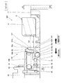
ブレーキ装置100は、図1及び図2に示すように、ガイドプレート5を介して第1,第2ブレーキライニング3,4をそれぞれ支持する第1,第2キャリパアーム12,14を有するブレーキ本体10と、台車(図示省略)取り付けられる支持枠20に軸方向に移動自在に支持されると共にブレーキ本体10を支持する第1,第2支持ピン21,22と、第1ブレーキライニングに支持されるガイドプレート5をブレーキ本体10に進退自在に支持する一対のアンカピン33と、圧縮空気の圧力によって第1,第2ブレーキライニング3,4をブレーキディスク2に押圧する押圧部35と、を備える。   As shown in FIGS. 1 and 2, the brake device 100 includes a brake body 10 having first and second caliper arms 12 and 14 that respectively support first and second brake linings 3 and 4 via a guide plate 5. And first and second support pins 21 and 22 that are supported by a support frame 20 attached to a carriage (not shown) so as to be movable in the axial direction and that support the brake body 10, and guides supported by the first brake lining. A pair of anchor pins 33 that support the plate 5 so as to be able to advance and retreat on the brake body 10 and a pressing portion 35 that presses the first and second brake linings 3 and 4 against the brake disc 2 by the pressure of compressed air are provided.

ブレーキ本体10は、ブレーキ装置100が鉄道車両に適用される場合には、支持枠20を介して台車に支持される。ブレーキ本体10は、ブレーキ装置100が鉄道車両以外の車両に適用される場合には、車体(図示省略)に支持される。   The brake body 10 is supported by the carriage via the support frame 20 when the brake device 100 is applied to a railway vehicle. The brake body 10 is supported by a vehicle body (not shown) when the brake device 100 is applied to a vehicle other than a railway vehicle.

ブレーキ本体10は、図1に示すように、ブレーキディスク2に跨るようにして延びる第1キャリパアーム12及び第2キャリパアーム14と、第1キャリパアーム12と第2キャリパアーム14とを連結するヨーク部13と、ブレーキ本体10を台車上に支持するための第1,第2ブラケット部15,16と、を有する。   As shown in FIG. 1, the brake body 10 includes a first caliper arm 12 and a second caliper arm 14 that extend across the brake disc 2, and a yoke that connects the first caliper arm 12 and the second caliper arm 14. Part 13 and first and second bracket parts 15 and 16 for supporting brake body 10 on the carriage.

第1支持ピン21の周辺構造と第2支持ピン22の周辺構造とは、後述するクランプ部40及びリリーススプリング60が取り付けられるか否かを除き、基本的な構成は同一である。よって、以下では、クランプ部40及びリリーススプリング60が取り付けられる第1支持ピン21の周辺構造について具体的に説明し、第2支持ピン22に関しては説明を省略する。   The basic structure of the peripheral structure of the first support pin 21 and the peripheral structure of the second support pin 22 is the same except that a clamp part 40 and a release spring 60 described later are attached. Therefore, below, the peripheral structure of the 1st support pin 21 to which the clamp part 40 and the release spring 60 are attached is demonstrated concretely, and description regarding the 2nd support pin 22 is abbreviate | omitted.

第1支持ピン21は、図3に示すように、支持枠20の挿通孔20aに挿通される。第1支持ピン21の両端部は、ブレーキ本体10の第1,第2ブラケット部15,16に各々連結される。第1支持ピン21は、車輪1の回転軸と平行に設けられると共に軸方向に移動可能に支持枠20に支持される。これにより、ブレーキ本体10は、第1支持ピン21の軸方向への移動が可能なように支持枠20に支持される。   As shown in FIG. 3, the first support pin 21 is inserted through the insertion hole 20 a of the support frame 20. Both end portions of the first support pin 21 are connected to the first and second bracket portions 15 and 16 of the brake body 10, respectively. The first support pin 21 is provided in parallel with the rotation axis of the wheel 1 and is supported by the support frame 20 so as to be movable in the axial direction. Accordingly, the brake body 10 is supported by the support frame 20 so that the first support pins 21 can move in the axial direction.

第1支持ピン21の露出部は、図1に示すように、ゴム製のブーツ25によって覆われ、ダスト等から保護されている。このようにして、ブレーキ本体10は、第1支持ピン21によって支持枠20に対して摺動可能にフローティング支持される。なお、図1を除き、ブーツ25の図示は省略する。   As shown in FIG. 1, the exposed portion of the first support pin 21 is covered with a rubber boot 25 and protected from dust and the like. In this manner, the brake body 10 is floating supported by the first support pins 21 so as to be slidable with respect to the support frame 20. Except for FIG. 1, illustration of the boot 25 is omitted.

第1,第2ブレーキライニング3,4は、ガイドプレート5に固定される裏板部3a,4aと、制動時にブレーキディスク2に当接する摩擦部材3b,4bと、を有する。摩擦部材3b,4bは、複数のセグメントからなり、裏板部3a,4aの表面に固定される。第1,第2ブレーキライニング3,4は、摩擦部材3b及び4bとブレーキディスク2との当接によって発生する摩擦力によって、車輪1の回転を制動する。   The first and second brake linings 3 and 4 have back plate portions 3a and 4a fixed to the guide plate 5, and friction members 3b and 4b that come into contact with the brake disc 2 during braking. The friction members 3b and 4b are composed of a plurality of segments, and are fixed to the surfaces of the back plate portions 3a and 4a. The first and second brake linings 3 and 4 brake the rotation of the wheel 1 by the frictional force generated by the contact between the friction members 3 b and 4 b and the brake disk 2.

第1,第2ブレーキライニング3,4は、非制動時には、それぞれブレーキディスク2と予め設定された所定の間隔をあけて対向する(図1に示す状態)。第1及び第2ブレーキライニング3,4は、制動時には、押圧部35による押圧力を受けてブレーキディスク2に向かってそれぞれ移動し、ブレーキディスク2に平行に当接して押圧される。   The first and second brake linings 3 and 4 are opposed to the brake disc 2 with a predetermined interval (state shown in FIG. 1) when not braking. During braking, the first and second brake linings 3 and 4 are each moved toward the brake disc 2 under the pressing force of the pressing portion 35 and are pressed against the brake disc 2 in parallel.

ガイドプレート5は、長手方向に沿って形成され第1ブレーキライニング3の裏板部3aが係合するアリ溝5aを有する。ガイドプレート5は、長手方向の両端部が、一対のアンカピン33によってブレーキ本体10に支持される。一方のアンカピン33は、ガイドプレート5の一端(図2では上端)をブレーキ本体10に回動可能に支持し、他方のアンカピン33は、ガイドプレート5の他端(図2では下端)をブレーキ本体10に係止する。   The guide plate 5 has a dovetail groove 5 a formed along the longitudinal direction and engaged with the back plate portion 3 a of the first brake lining 3. Both ends of the guide plate 5 in the longitudinal direction are supported by the brake body 10 by a pair of anchor pins 33. One anchor pin 33 rotatably supports one end (upper end in FIG. 2) of the guide plate 5 on the brake body 10, and the other anchor pin 33 supports the other end (lower end in FIG. 2) of the guide plate 5 on the brake body. 10 is locked.

ブレーキ本体10の第1キャリパアーム12には、長手方向(図2中上下方向)の両端部に配置される一対のアジャスタ30と、一対のアジャスタ30の間に配置される押圧部35と、が設けられる。   The first caliper arm 12 of the brake main body 10 includes a pair of adjusters 30 disposed at both ends in the longitudinal direction (vertical direction in FIG. 2) and a pressing portion 35 disposed between the pair of adjusters 30. Provided.

アジャスタ30は、非制動時にブレーキディスク2に対する第1ブレーキライニング3の相対位置を一定に調整するものである。アジャスタ30は、アンカボルト32によってブレーキ本体10の上下端部にそれぞれ締結される。   The adjuster 30 adjusts the relative position of the first brake lining 3 with respect to the brake disc 2 to a constant level when not braking. The adjusters 30 are fastened to the upper and lower ends of the brake body 10 by anchor bolts 32, respectively.

アジャスタ30は、図1に示すように、アンカボルト32によってブレーキ本体10に固定されるライニング受け31と、ライニング受け31に対して進退可能に設けられて第1ブレーキライニング3をブレーキ本体10に支持するアンカピン33と、第1ブレーキライニング3をブレーキディスク2から離間する方向に付勢するリターンスプリング(図示省略)と、非制動時に第1ブレーキライニング3とブレーキディスク2との隙間を一定に調整する隙間調整機構(図示省略)と、を備える。   As shown in FIG. 1, the adjuster 30 is provided with a lining receiver 31 fixed to the brake body 10 by an anchor bolt 32, and is provided so as to be able to advance and retreat with respect to the lining receiver 31. The anchor pin 33, the return spring (not shown) for urging the first brake lining 3 away from the brake disc 2, and the gap between the first brake lining 3 and the brake disc 2 are adjusted to be constant during non-braking. A gap adjusting mechanism (not shown).

アンカピン33は、第1ブレーキライニング3がブレーキディスク2に近接する際に、第1ブレーキライニング3とともに変位するガイドプレート5によってライニング受け31から引き出されて軸方向に変位する。アンカピン33は、第1ブレーキライニング3がブレーキディスク2に摺接する制動時に、摩擦力によってブレーキディスク2が第1ブレーキライニング3を周方向に移動させようとするのに抗して、第1ブレーキライニング3を保持する。アンカピン33の内周に、リターンスプリングと隙間調整機構とが収装される。   When the first brake lining 3 is close to the brake disc 2, the anchor pin 33 is pulled out from the lining receiver 31 by the guide plate 5 that is displaced together with the first brake lining 3 and is displaced in the axial direction. The anchor pin 33 resists the brake disc 2 from moving the first brake lining 3 in the circumferential direction by frictional force during braking when the first brake lining 3 is in sliding contact with the brake disc 2. 3 is held. A return spring and a gap adjusting mechanism are accommodated on the inner periphery of the anchor pin 33.

リターンスプリングは、アンカピン33の内周に圧縮して介装されるコイルばねである。ブレーキ装置100が制動状態から非制動状態になったときには、リターンスプリングの付勢力によって、アンカピン33がガイドプレート5を介して第1ブレーキライニング3を押し戻し、第1ブレーキライニング3をブレーキディスク2から所定の距離だけ離間させる。これにより、非制動時における第1ブレーキライニング3とブレーキディスク2との距離を調整して、ブレーキディスク2の放熱性を良好にすることができる。なお、制動状態とは、後述する押圧部35によって第1,第2ブレーキライニング3,4がブレーキディスク2に押圧されている状態のことである。また、非制動状態とは、押圧部35によってブレーキディスク2に押圧される押圧力が第1,第2ブレーキライニング3,4に作用しない状態のことである。   The return spring is a coil spring that is compressed and interposed on the inner periphery of the anchor pin 33. When the brake device 100 changes from the braking state to the non-braking state, the anchor pin 33 pushes back the first brake lining 3 via the guide plate 5 by the biasing force of the return spring, and the first brake lining 3 is removed from the brake disc 2 by a predetermined amount. Are separated by a distance of. Thereby, the distance of the 1st brake lining 3 and the brake disc 2 at the time of non-braking can be adjusted, and the heat dissipation of the brake disc 2 can be made favorable. The braking state is a state in which the first and second brake linings 3 and 4 are pressed against the brake disc 2 by a pressing portion 35 described later. The non-braking state is a state in which the pressing force pressed against the brake disk 2 by the pressing portion 35 does not act on the first and second brake linings 3 and 4.

隙間調整機構は、非制動時におけるリターンスプリングの付勢力による第1ブレーキライニング3の戻し量を一定に調整する。つまり、隙間調整機構は、非制動時における第1ブレーキライニング3とブレーキディスク2の間隔を常に一定に保つ。   The clearance adjustment mechanism adjusts the return amount of the first brake lining 3 to be constant by the urging force of the return spring during non-braking. That is, the gap adjusting mechanism always keeps the distance between the first brake lining 3 and the brake disc 2 during non-braking.

第1ブレーキライニング3の摩耗量が小さく、制動時におけるアンカピン33のストローク量が小さいうちは、非制動時には、アンカピン33が制動前における元の位置まで戻る。   While the amount of wear of the first brake lining 3 is small and the stroke amount of the anchor pin 33 at the time of braking is small, the anchor pin 33 returns to the original position before braking at the time of non-braking.

これに対して、第1ブレーキライニング3の摩耗が進行し、制動時におけるアンカピン33の移動量が大きくなった場合において、非制動時には、隙間調整機構が非制動時における第1ブレーキライニング3の位置を、摩耗した厚さの分だけ前進させる。これにより、非制動時における第1ブレーキライニング3とブレーキディスク2との間隔を常に一定に保つことができる。   On the other hand, when wear of the first brake lining 3 progresses and the amount of movement of the anchor pin 33 during braking increases, the position of the first brake lining 3 during non-braking when the clearance adjustment mechanism is not braked. Is advanced by the worn thickness. Thereby, the space | interval of the 1st brake lining 3 and the brake disc 2 at the time of non-braking can be always kept constant.

押圧部35は、圧縮空気の圧力により第1ブレーキライニング3をブレーキディスク2に押圧すると共にその反力によってブレーキ本体10を第1支持ピン21の軸方向に移動させて第2ブレーキライニング4をブレーキディスク2に押圧する。   The pressing portion 35 presses the first brake lining 3 against the brake disc 2 by the pressure of the compressed air and moves the brake body 10 in the axial direction of the first support pin 21 by the reaction force to brake the second brake lining 4. Press against the disc 2.

押圧部35は、第1、第2ブレーキライニング3,4をブレーキディスク2に押圧するものであれば、任意の構成とすることができる。このため、押圧部35の詳細な説明は省略するが、例えば、押圧部35は、内部に設けられる圧力室おける空気圧を調整することでダイヤフラムを変形させ、ダイヤフラムの変形によってピストンをシリンダから退出させる。これにより、押圧部35は、ガイドプレート5を介して第1ブレーキライニング3をブレーキディスク2に向けて図1中右方向に押圧し、その反力によってブレーキ本体10を図1中左方向へ移動させて第2ブレーキライニング4をブレーキディスク2に向けて引き寄せる。このようにして、ブレーキディスク2が第1,第2ブレーキライニング3,4によって挟持されて、制動力としての摩擦力が発揮される。   The pressing part 35 can have any configuration as long as it presses the first and second brake linings 3, 4 against the brake disk 2. For this reason, although detailed description of the press part 35 is abbreviate | omitted, for example, the press part 35 deform | transforms a diaphragm by adjusting the air pressure in the pressure chamber provided inside, and makes a piston retract from a cylinder by the deformation | transformation of a diaphragm. . Thus, the pressing portion 35 presses the first brake lining 3 toward the brake disk 2 via the guide plate 5 in the right direction in FIG. 1, and the reaction force causes the brake body 10 to move in the left direction in FIG. 1. Then, the second brake lining 4 is pulled toward the brake disc 2. In this way, the brake disc 2 is sandwiched between the first and second brake linings 3 and 4, and a frictional force as a braking force is exhibited.

なお、以下では、図1に示すように、ブレーキ装置100の制動時におけるブレーキ本体10の移動方向、言い換えれば第2ブレーキライニング4がブレーキディスク2に近づいて押圧されるようなブレーキ本体10の移動方向を「押圧方向」と称する。また、反対に第2ブレーキライニング4とブレーキディスク2とが離間するようなブレーキ本体10の移動方向を「解除方向」と称する。   In the following, as shown in FIG. 1, the movement direction of the brake body 10 during braking of the brake device 100, in other words, the movement of the brake body 10 such that the second brake lining 4 approaches and presses the brake disk 2. The direction is referred to as a “pressing direction”. On the contrary, the moving direction of the brake body 10 in which the second brake lining 4 and the brake disc 2 are separated from each other is referred to as a “release direction”.

ブレーキ装置100は、図3に示すように、支持枠20の挿通孔20a内に設けられ第1支持ピン21を摺動自在に支持する球面ベアリング26と、支持枠20の挿通孔20a内であって球面ベアリング26の軸方向両側に設けられ第1支持ピン21を摺動自在に支持する一対のゴム製ブッシュ27,28と、支持枠20外の露出部に設けられ第1支持ピン21をクランプ可能なクランプ部40と、制動時のブレーキ本体10の移動に抗するように反力を発揮してクランプ部40を付勢する付勢部材としてのリリーススプリング60と、をさらに備える。   As shown in FIG. 3, the brake device 100 includes a spherical bearing 26 provided in the insertion hole 20 a of the support frame 20 and slidably supporting the first support pin 21, and the insertion hole 20 a of the support frame 20. A pair of rubber bushes 27 and 28 provided on both axial sides of the spherical bearing 26 for slidably supporting the first support pin 21 and an exposed portion outside the support frame 20 for clamping the first support pin 21 It further includes a possible clamp portion 40 and a release spring 60 as an urging member that exerts a reaction force to urge the clamp portion 40 against the movement of the brake body 10 during braking.

また、支持枠20は、第2ブラケット部16側の端部に設けられクランプ部40との間でリリーススプリング60を軸方向に支持するカバー部23を有する。カバー部23は、径方向内側に延びる環状部23aと、軸方向に延びる円筒部23bと、を有する(図4参照)。   The support frame 20 includes a cover portion 23 that is provided at an end portion on the second bracket portion 16 side and supports the release spring 60 in the axial direction between the support frame 20 and the clamp portion 40. The cover part 23 has an annular part 23a extending radially inward and a cylindrical part 23b extending in the axial direction (see FIG. 4).

図3に示すように、球面ベアリング26は、互いに摺動可能に嵌合する軸受面を有する外輪26a及び内輪26bを備える。外輪26aと内輪26bとは、相対回転可能に係合する。   As shown in FIG. 3, the spherical bearing 26 includes an outer ring 26a and an inner ring 26b having bearing surfaces that are slidably fitted to each other. The outer ring 26a and the inner ring 26b are engaged with each other so as to be relatively rotatable.

外輪26aは、支持枠20の挿通孔20aの内周面に嵌合して設けられる。内輪26bには、第1支持ピン21が摺動自在に挿通する。これにより、球面ベアリング26は、支持枠20に対してブレーキ本体10を揺動可能に支持すると共に支持枠20に対して第1支持ピン21の軸方向(車輪1の回転軸方向)に摺動可能にフローティング支持する。   The outer ring 26 a is provided by being fitted to the inner peripheral surface of the insertion hole 20 a of the support frame 20. The first support pin 21 is slidably inserted into the inner ring 26b. Accordingly, the spherical bearing 26 supports the brake body 10 so as to be swingable with respect to the support frame 20 and slides in the axial direction of the first support pin 21 (the rotation axis direction of the wheel 1) with respect to the support frame 20. Support floating as possible.

リリーススプリング60は、第1支持ピン21をクランプするクランプ部40を解除方向に向けて付勢するコイルばねである。   The release spring 60 is a coil spring that biases the clamp portion 40 that clamps the first support pin 21 in the release direction.

制動時においてブレーキ本体10及び第1支持ピン21が押圧方向へ移動すると、その移動に対してリリーススプリング60が反力を発生して、ブレーキ本体10及び第1支持ピン21がクランプ部40を介して解除方向に付勢される。これにより、非制動時にリリーススプリング60の付勢力によってブレーキ本体10及び第1支持ピン21が解除方向に移動し、第2ブレーキライニング4とブレーキディスク2との間に所定の隙間が形成される。   When the brake body 10 and the first support pin 21 move in the pressing direction during braking, the release spring 60 generates a reaction force against the movement, and the brake body 10 and the first support pin 21 are interposed via the clamp portion 40. Is biased in the release direction. As a result, the brake body 10 and the first support pin 21 are moved in the release direction by the urging force of the release spring 60 during non-braking, so that a predetermined gap is formed between the second brake lining 4 and the brake disc 2.

また、ブレーキ本体10及び第1支持ピン21は、非制動状態であっても、リリーススプリング60によって解除方向に付勢される。これにより、非制動時において、車両の振動等によりブレーキ本体10及び第1支持ピン21が押圧方向に移動することが防止される。   Further, the brake body 10 and the first support pin 21 are biased in the release direction by the release spring 60 even in the non-braking state. This prevents the brake main body 10 and the first support pin 21 from moving in the pressing direction due to vehicle vibration or the like during non-braking.

クランプ部40は、図4に示すように、くさび空間を第1支持ピン21の外周面との間で形成するくさび面41aを有するくさび部材としてのリテーナ41と、くさび空間に収容される転動体42と、転動体42が第1支持ピン21の軸方向からくさび面41aに押し付けられるようにリテーナ41を押圧する押付部材としてのクランプスプリング43と、リテーナ41と第1支持ピン21との径方向の間に設けられ内外周面に開口する貫通孔45aを有する筒状のインナー部材44と、を有する。   As shown in FIG. 4, the clamp portion 40 includes a retainer 41 as a wedge member having a wedge surface 41 a that forms a wedge space with the outer peripheral surface of the first support pin 21, and a rolling element accommodated in the wedge space. 42, a radial direction of the retainer 41 and the first support pin 21, a clamp spring 43 as a pressing member that presses the retainer 41 so that the rolling element 42 is pressed against the wedge surface 41 a from the axial direction of the first support pin 21. And a cylindrical inner member 44 having a through hole 45a that is open between the inner and outer peripheral surfaces.

リテーナ41は、インナー部材44の外周に設けられる筒状の部材である。リテーナ41は、第1支持ピン21の軸方向に対して傾斜するテーパ状のくさび面41aを有する。リテーナ41は、くさび面41aによって、第1支持ピン21の軸方向に沿って径方向の間隔が徐々に狭くなるくさび空間を第1支持ピン21の外周面との間で形成する。   The retainer 41 is a cylindrical member provided on the outer periphery of the inner member 44. The retainer 41 has a tapered wedge surface 41 a that is inclined with respect to the axial direction of the first support pin 21. The retainer 41 forms a wedge space with the outer peripheral surface of the first support pin 21 by the wedge surface 41 a, in which the radial distance gradually decreases along the axial direction of the first support pin 21.

転動体42は、球状に形成され、貫通孔45aを通じて第1支持ピン21の外周面とくさび面41aとの両方に接触する。なお、転動体42は、球状に限らず円筒形状に形成されてもよい。また、図4では、単一の転動体42を図示しているが、転動体42の数はこれに限らず、複数設けられてもよい。複数の転動体42が設けられることにより、クランプ部40が安定して第1支持ピン21を支持することができる。   The rolling element 42 is formed in a spherical shape, and contacts both the outer peripheral surface of the first support pin 21 and the wedge surface 41a through the through hole 45a. In addition, the rolling element 42 may be formed not only in a spherical shape but in a cylindrical shape. 4 shows a single rolling element 42, the number of rolling elements 42 is not limited to this, and a plurality of rolling elements 42 may be provided. By providing the plurality of rolling elements 42, the clamp portion 40 can stably support the first support pin 21.

インナー部材44は、貫通孔45aが形成される筒状の本体部45と、本体部45の外周面から径方向外側に延びて形成されリテーナ41との間でクランプスプリング43を支持する受け部としてのばね受け部46と、本体部45の一端から径方向外側に延びて形成され支持枠20のカバー部23との間でリリーススプリング60を支持する支持部としてのフランジ部47と、ばね受け部46に対してフランジ部47とは反対側における本体部45の外周面から径方向外側に延びて形成される規制部48と、を有する。   The inner member 44 is formed as a receiving portion that supports the clamp spring 43 between the cylindrical main body 45 in which the through hole 45 a is formed and the retainer 41 that is formed to extend radially outward from the outer peripheral surface of the main body 45. A spring receiving portion 46, a flange portion 47 as a supporting portion for supporting the release spring 60 between the one end of the main body portion 45 and the cover portion 23 of the support frame 20 formed to extend radially outward, and a spring receiving portion. And a regulating portion 48 formed to extend radially outward from the outer peripheral surface of the main body portion 45 on the opposite side of the flange portion 47 with respect to 46.

ばね受け部46は、貫通孔45aを挟んでフランジ部47とは反対側に設けられる。クランプスプリング43は、ばね受け部46とリテーナ41との間に圧縮状態で介装され、転動体42がくさび面41aに押し付けられるようにリテーナ41を図4中右方向に付勢する。これにより、転動体42は、くさび空間において幅が狭い部分(図4中左側部分)に向けて押し込まれる。よって、クランプ部40と第1支持ピン21との相対移動がくさび効果によって規制される。クランプ部40は、このようにして第1支持ピン21をクランプする。   The spring receiving portion 46 is provided on the side opposite to the flange portion 47 across the through hole 45a. The clamp spring 43 is interposed between the spring receiving portion 46 and the retainer 41 in a compressed state, and urges the retainer 41 rightward in FIG. 4 so that the rolling element 42 is pressed against the wedge surface 41a. Thereby, the rolling element 42 is pushed toward the narrow part (the left part in FIG. 4) in the wedge space. Therefore, the relative movement between the clamp part 40 and the first support pin 21 is restricted by the wedge effect. The clamp part 40 clamps the first support pin 21 in this way.

ばね受け部46と規制部48とは、カバー部23の環状部23aを挟んで軸方向の両側に配置される。図4に示すように、ブレーキ装置100の非制動状態では、規制部48と環状部23aとが当接する。規制部48と環状部23aとが当接することにより、解除方向へのクランプ部40のそれ以上の移動が規制される。また、クランプ部40がブレーキ本体10及び第1支持ピン21と共に押圧方向へ移動して、ばね受け部46が環状部23aに当接すると、押圧方向へのそれ以上のブレーキ本体10及び第1支持ピン21の移動が規制される。つまり、第1支持ピン21の軸方向へのクランプ部40の移動は、ばね受け部46と規制部48との軸方向の距離によって規定される。   The spring receiving portion 46 and the restricting portion 48 are disposed on both sides in the axial direction with the annular portion 23a of the cover portion 23 interposed therebetween. As shown in FIG. 4, when the brake device 100 is in a non-braking state, the restricting portion 48 and the annular portion 23a come into contact with each other. When the restricting portion 48 and the annular portion 23a abut, further movement of the clamp portion 40 in the releasing direction is restricted. Further, when the clamp part 40 moves in the pressing direction together with the brake body 10 and the first support pin 21 and the spring receiving part 46 comes into contact with the annular part 23a, the brake body 10 and the first support further in the pressing direction. The movement of the pin 21 is restricted. That is, the movement of the clamp portion 40 in the axial direction of the first support pin 21 is defined by the axial distance between the spring receiving portion 46 and the restricting portion 48.

次に、図4から図7を参照して、ブレーキ装置100の作用について説明する。   Next, the operation of the brake device 100 will be described with reference to FIGS.

図5から図8では、非制動状態における第1支持ピン21を破線で示す。また、以下では、クランプ部40のフランジ部47とブレーキ本体10の第2ブラケット部16との間の軸方向距離を、クランプ部40とブレーキ本体10との間の「相対距離」と称する。また、図4に示すように、第2ブレーキライニング4が摩耗していない状態における相対距離を「L0」とする。   5 to 8, the first support pin 21 in the non-braking state is indicated by a broken line. Hereinafter, the axial distance between the flange portion 47 of the clamp portion 40 and the second bracket portion 16 of the brake body 10 is referred to as a “relative distance” between the clamp portion 40 and the brake body 10. Also, as shown in FIG. 4, the relative distance when the second brake lining 4 is not worn is “L0”.

鉄道車両の走行時には、車輪1は高速で回転している。ここで、運転士の操作等によってブレーキ装置100が制動状態に切り換えられると、空気圧源から供給される圧縮空気によって、押圧部35(図1参照)がガイドプレート5を介して第1ブレーキライニング3を車輪1に設けられたブレーキディスク2に向けて押圧する。   When the railway vehicle travels, the wheel 1 rotates at a high speed. Here, when the brake device 100 is switched to the braking state by an operation of the driver or the like, the pressing portion 35 (see FIG. 1) is pressed via the guide plate 5 by the compressed air supplied from the air pressure source to the first brake lining 3. Is pressed toward the brake disc 2 provided on the wheel 1.

この際、ブレーキ本体10には、押圧部35が第1ブレーキライニング3を押圧する反力が作用する。これにより、ブレーキ本体10は、図5に示すように、クランプ部40との相対距離L0を保ったまま、押圧部35の反力によって第1支持ピン21及びクランプ部40と共にリリーススプリング60の付勢力に抗して押圧方向に移動する。よって、第2ブレーキライニング4がブレーキディスク2に向けて引き寄せられ、第1、第2ブレーキライニング3,4がブレーキディスク2の両側から当接して摩擦力が発生し、車輪1の回転は制動される。これにより、鉄道車両は、速度が低下してやがて停止することとなる。   At this time, a reaction force that the pressing portion 35 presses the first brake lining 3 acts on the brake body 10. Accordingly, as shown in FIG. 5, the brake main body 10 is attached with the release spring 60 together with the first support pin 21 and the clamp portion 40 by the reaction force of the pressing portion 35 while maintaining the relative distance L0 with the clamp portion 40. It moves in the pressing direction against the force. Therefore, the second brake lining 4 is drawn toward the brake disc 2, the first and second brake linings 3 and 4 come into contact with both sides of the brake disc 2, and frictional force is generated, and the rotation of the wheel 1 is braked. The As a result, the railway vehicle will eventually stop due to a decrease in speed.

運転士の操作等によってブレーキ装置100による車輪1の制動が解除されると、アジャスタ30内部に設けられたリターンスプリングの復元力によって、第1ブレーキライニング3はブレーキディスク2に当接した状態から離間する。また、圧力室内の圧縮空気は通孔(図示省略)から排出されて、第1ブレーキライニング3は制動前の位置に戻る。   When the braking of the wheel 1 by the brake device 100 is released by the driver's operation or the like, the first brake lining 3 is separated from the state in contact with the brake disc 2 by the restoring force of the return spring provided in the adjuster 30. To do. Also, the compressed air in the pressure chamber is discharged from a through hole (not shown), and the first brake lining 3 returns to the position before braking.

これにより、ブレーキディスク2と第1ブレーキライニング3とは、隙間調整機構の作用によって再び一定の間隔をもって対峙する。   As a result, the brake disc 2 and the first brake lining 3 face each other at a constant interval again by the action of the gap adjusting mechanism.

一方、圧力室内の圧縮空気が排出されることにより、ブレーキ本体10、第1支持ピン21、及びクランプ部40は、制動時に圧縮されたリリーススプリング60の付勢力を復元力として受けて、解除方向に向けて移動する。ブレーキ本体10、第1支持ピン21、及びクランプ部40は、規制部48が環状部23aに当接するまで解除方向に向けて移動して、制動前の状態(図4に示す状態)に戻る。   On the other hand, when the compressed air in the pressure chamber is discharged, the brake body 10, the first support pin 21, and the clamp portion 40 receive the urging force of the release spring 60 compressed during braking as a restoring force, and the release direction Move towards The brake body 10, the first support pin 21, and the clamp part 40 move in the release direction until the restricting part 48 contacts the annular part 23a, and return to the state before braking (the state shown in FIG. 4).

これにより、ブレーキディスク2と第2ブレーキライニング4とは、互いに離間して再び一定の隙間をもって対峙する。よって、ブレーキ装置100の解除時における第2ブレーキライニング4とブレーキディスク2との接触が防止される。これにより、第2ブレーキライニング4の摩耗が抑制されて、第2ブレーキライニング4の寿命を向上させることができる。また、車輪1は、ブレーキ装置100の影響を受けることなく回転することが可能となる。   Thereby, the brake disc 2 and the second brake lining 4 are separated from each other and face each other with a certain gap again. Therefore, contact between the second brake lining 4 and the brake disc 2 when the brake device 100 is released is prevented. Thereby, abrasion of the 2nd brake lining 4 is suppressed and the life of the 2nd brake lining 4 can be improved. Further, the wheel 1 can rotate without being affected by the brake device 100.

第1ブレーキライニング3の摩擦部材3bが摩耗すると、隙間調整機構によりガイドプレート5は、摩擦部材3bが摩耗した分だけブレーキディスク2に向かって前進する。このため、第1ブレーキライニング3とブレーキディスク2との間の隙間は、一定に保たれる。   When the friction member 3b of the first brake lining 3 is worn, the guide plate 5 moves forward toward the brake disk 2 by the amount of wear of the friction member 3b by the gap adjusting mechanism. For this reason, the gap between the first brake lining 3 and the brake disc 2 is kept constant.

これに対し、第2キャリパアーム14には隙間調整機構が設けられないため、第2ブレーキライニング4の摩耗部材4bが摩耗(以下、単に「第2ブレーキライニング4が摩耗」とする。)すると、第2ブレーキライニング4とブレーキディスク2との間の隙間は大きくなる。このため、非制動状態から第2ブレーキライニング4とブレーキディスク2とを接触させて制動状態とするために押圧方向へ向けて移動するブレーキ本体10の移動量が大きくなる。   In contrast, since the gap adjusting mechanism is not provided in the second caliper arm 14, when the wear member 4b of the second brake lining 4 is worn (hereinafter simply referred to as “the second brake lining 4 is worn”). The gap between the second brake lining 4 and the brake disc 2 is increased. For this reason, the amount of movement of the brake body 10 that moves in the pressing direction in order to bring the second brake lining 4 and the brake disc 2 into contact with each other from the non-braking state to make the braking state increases.

ここで、ブレーキ装置100では、非制動状態(図4に示す状態)からブレーキ本体10が予め定められた基準移動量S0だけ押圧方向に移動すると、第1支持ピン21とクランプ部40とを相対移動させる力が、クランプ部40による第1支持ピン21をクランプする力(以下、「クランプ力」と称する。)と釣り合うように、クランプ部40及びリリーススプリング60が構成される。   Here, in the brake device 100, when the brake main body 10 moves in the pressing direction by a predetermined reference movement amount S0 from the non-braking state (the state shown in FIG. 4), the first support pin 21 and the clamp portion 40 are moved relative to each other. The clamp part 40 and the release spring 60 are configured so that the force to be moved is balanced with the force (hereinafter referred to as “clamping force”) that clamps the first support pin 21 by the clamp part 40.

具体的に説明すると、制動時において、第1支持ピン21とクランプ部40とを相対移動させる力(以下、単に「相対移動させる力」と称する。)は、押圧部35からブレーキ本体10に作用する反力と、クランプ部40に作用しクランプ部40の移動量に応じて変化するリリーススプリング60の付勢力と、によるものである。つまり、相対移動させる力は、ブレーキ本体10及び第1支持ピン21に対して押圧方向に作用する押圧部35の反力と、クランプ部40に対して解除方向に作用するリリーススプリング60の付勢力と、によるものである。押圧部35の反力は、所望の制動力に応じて定められるため、相対移動させる力は、主にリリーススプリング60の付勢力によって決定される。   More specifically, during braking, a force that moves the first support pin 21 and the clamp portion 40 relative to each other (hereinafter simply referred to as “relatively moving force”) acts on the brake body 10 from the pressing portion 35. And the urging force of the release spring 60 that acts on the clamp portion 40 and changes according to the amount of movement of the clamp portion 40. In other words, the relative moving force is the reaction force of the pressing portion 35 that acts on the brake body 10 and the first support pin 21 in the pressing direction, and the biasing force of the release spring 60 that acts on the clamping portion 40 in the releasing direction. It is due to. Since the reaction force of the pressing portion 35 is determined according to a desired braking force, the force for relative movement is mainly determined by the urging force of the release spring 60.

クランプ部40のクランプ力は、相対移動させる力に対して転動体42と第1支持ピン21との間で生じる摩擦力である。クランプ力は、クランプスプリング43の付勢力、くさび面41aの形状、転動体42の形状、及び第1支持ピン21と転動体42との間の摩擦係数などにより決定される。これらを適切に設定することにより、所望のクランプ力を得ることができる。クランプ部40のクランプ力は、ブレーキ本体10の移動量に関わらず、一定である。なお、図4から図7では、クランプ力及び相対移動させる力を模式的に矢印で示している。   The clamping force of the clamp part 40 is a frictional force generated between the rolling element 42 and the first support pin 21 with respect to the force of relative movement. The clamping force is determined by the biasing force of the clamp spring 43, the shape of the wedge surface 41a, the shape of the rolling element 42, the coefficient of friction between the first support pin 21 and the rolling element 42, and the like. By appropriately setting these, a desired clamping force can be obtained. The clamping force of the clamping unit 40 is constant regardless of the amount of movement of the brake body 10. 4 to 7, the clamping force and the relative moving force are schematically indicated by arrows.

以下、クランプ部40の作用について具体的に説明する。   Hereinafter, the operation of the clamp unit 40 will be specifically described.

図5に示すように、第2ブレーキライニング4の摩耗が小さくブレーキ本体10の移動量が基準移動量S0よりも小さい移動量S1である場合には、制動状態における相対移動させる力がクランプ部40のクランプ力を上回らず、クランプ部40と第1支持ピン21とは相対移動しない。つまり、制動時には、第1支持ピン21がクランプ部40によってクランプされた状態を維持し相対距離L0を保ったまま、ブレーキ本体10、第1支持ピン21、及びクランプ部40が一体となって押圧方向へ移動する。   As shown in FIG. 5, when the wear of the second brake lining 4 is small and the movement amount of the brake body 10 is the movement amount S <b> 1 smaller than the reference movement amount S <b> 0, the relative movement force in the braking state is the clamp portion 40. The clamping force and the first support pin 21 do not move relative to each other. That is, at the time of braking, the brake body 10, the first support pin 21, and the clamp part 40 are pressed together while maintaining the state in which the first support pin 21 is clamped by the clamp part 40 and maintaining the relative distance L0. Move in the direction.

図6に示すように、制動時のブレーキ本体10の移動量が基準移動量S0となると、リリーススプリング60による付勢力と押圧部35の反力とによる相対移動させる力がクランプ部40のクランプ力と釣り合う。以下、ブレーキ本体10が基準移動量S0だけ移動した際のリリーススプリング60の付勢力を「基準付勢力」と称する。   As shown in FIG. 6, when the amount of movement of the brake body 10 at the time of braking becomes the reference amount of movement S 0, the force of relative movement by the urging force by the release spring 60 and the reaction force of the pressing portion 35 is the clamping force of the clamping portion 40. Balance with. Hereinafter, the urging force of the release spring 60 when the brake body 10 moves by the reference movement amount S0 is referred to as “reference urging force”.

ブレーキ本体10が基準移動量S0を超えて押圧方向へ移動しようとすると、リリーススプリング60がさらに圧縮されることになるため、相対移動させる力が転動体42と第1支持ピン21との間で生じる摩擦力(クランプ力)を上回る。これにより、クランプ部40のクランプが解除されることとなり、第1支持ピン21及びブレーキ本体10は基準移動量S0を超えて押圧方向へ移動する一方で、クランプ部40はそれ以上押圧方向には移動しない。このようにして、クランプ部40と第1支持ピン21及びブレーキ本体10との相対移動が許容される。   When the brake body 10 tries to move in the pressing direction beyond the reference movement amount S0, the release spring 60 is further compressed, so that the relative moving force is generated between the rolling element 42 and the first support pin 21. The friction force (clamping force) generated is exceeded. As a result, the clamp of the clamp portion 40 is released, and the first support pin 21 and the brake body 10 move in the pressing direction beyond the reference movement amount S0, while the clamp portion 40 does not move in the pressing direction any more. Do not move. In this way, relative movement between the clamp portion 40, the first support pin 21, and the brake body 10 is allowed.

このように、第1実施形態に係るブレーキ装置100では、相対移動させる力が転動体42と第1支持ピン21との間の摩擦力(クランプ力)を上回ることで、クランプ部40と第1支持ピン21とが相対移動する状態が、クランプ部40による第1支持ピンのクランプが解除された状態である。なお、リリーススプリング60は、ブレーキ本体10及び第1支持ピン21が基準移動量S0を超えて移動しても、クランプ部40が押圧方向へ移動しないため、基準付勢力を発揮する状態からさらに圧縮されることはない。   As described above, in the brake device 100 according to the first embodiment, the force of relative movement exceeds the frictional force (clamping force) between the rolling element 42 and the first support pin 21, so The state in which the support pin 21 moves relative to the support pin 21 is a state in which the clamp of the first support pin by the clamp unit 40 is released. The release spring 60 is further compressed from a state in which the reference urging force is exerted because the clamp portion 40 does not move in the pressing direction even when the brake body 10 and the first support pin 21 move beyond the reference movement amount S0. It will never be done.

第1支持ピン21及びブレーキ本体10は、図7に示すように、ブレーキ装置100が制動状態となるような移動量S2までクランプ部40に対して相対移動する。この際、ブレーキ本体10とクランプ部40との相対距離は、L0よりも小さいL1になる。ブレーキ装置100の制動が解除されると、押圧部35からブレーキ本体10に作用する反力がなくなる。このため、ブレーキ本体10及び第1支持ピン21とクランプ部40とを相対移動させる力がなくなり、相対移動させる力がクランプ力を下回る。よって、再び、第1支持ピン21がクランプ部40と相対移動しないクランプされた状態となる。これにより、リリーススプリング60の基準付勢力によって、ブレーキ本体10、第1支持ピン21、及びクランプ部40が解除方向に向けて一体となって移動する。したがって、ブレーキディスク2と第2ブレーキライニング4とが互いに離間して再び一定の隙間をもって対峙する。   As shown in FIG. 7, the first support pin 21 and the brake main body 10 move relative to the clamp portion 40 up to a movement amount S <b> 2 so that the brake device 100 enters a braking state. At this time, the relative distance between the brake body 10 and the clamp portion 40 is L1 which is smaller than L0. When the braking of the brake device 100 is released, the reaction force acting on the brake body 10 from the pressing portion 35 disappears. For this reason, the force which moves the brake main body 10 and the 1st support pin 21, and the clamp part 40 relatively is lost, and the force which moves relatively is less than a clamp force. Therefore, the first support pin 21 is again clamped so as not to move relative to the clamp portion 40. As a result, the brake body 10, the first support pin 21, and the clamp portion 40 move together in the release direction by the reference biasing force of the release spring 60. Therefore, the brake disc 2 and the second brake lining 4 are separated from each other and again face each other with a certain gap.

図5から図7を参照してより詳細に説明すると、クランプ部40は、クランプが解除された状態では押圧方向へ移動せず、ブレーキ本体10及び第1支持ピン21は、基準移動量S0を超えて押圧方向へ移動する。クランプが解除されたクランプ部40は、ブレーキ装置100の制動が解除された後に、再び第1支持ピン21をクランプする。   More specifically, referring to FIGS. 5 to 7, the clamp portion 40 does not move in the pressing direction when the clamp is released, and the brake body 10 and the first support pin 21 have the reference movement amount S0. It moves beyond the pressing direction. The clamp part 40 whose clamp is released clamps the first support pin 21 again after the braking of the brake device 100 is released.

図5及び図6に示すように、クランプ部40は、ブレーキ本体10の移動量が基準移動量S0以下のクランプ解除前では、ブレーキ本体10とクランプ部40との相対距離がL0の位置で第1支持ピン21をクランプしている。これに対し、図7に示すように、クランプ部40がブレーキ本体10及び第1支持ピン21と相対移動して再び第1支持ピン21をクランプした状態では、相対距離がL0よりも小さいL1の位置で第1支持ピン21をクランプする。つまり、第1支持ピン21をクランプする位置が、クランプが解除される前と比べて、クランプ部40とブレーキ本体10との相対移動距離Tだけずれる。このため、リリーススプリング60によってブレーキ本体10が解除方向に戻されると、制動解除後のブレーキ本体10の位置は、押圧方向に相対移動距離T分だけずれた位置となる。   As shown in FIG. 5 and FIG. 6, the clamp unit 40 is positioned at a position where the relative distance between the brake body 10 and the clamp unit 40 is L0 before the release of the clamp where the movement amount of the brake body 10 is equal to or less than the reference movement amount S0. 1 The support pin 21 is clamped. On the other hand, as shown in FIG. 7, in a state where the clamp portion 40 moves relative to the brake body 10 and the first support pin 21 and clamps the first support pin 21 again, the relative distance is L1 which is smaller than L0. The first support pin 21 is clamped in position. That is, the position where the first support pin 21 is clamped is shifted by the relative movement distance T between the clamp portion 40 and the brake body 10 as compared to before the clamp is released. For this reason, when the brake body 10 is returned to the release direction by the release spring 60, the position of the brake body 10 after the release of the brake is a position shifted by the relative movement distance T in the pressing direction.

ここで、図7に示すように、ブレーキ本体10が基準移動量S0を超えて移動した状態であっても、クランプ部40は押圧方向に移動しないため、リリーススプリング60の解除方向への戻し量は、基準移動量S0で一定である。よって、ブレーキ本体10が基準移動量S0を超えて移動して車輪1を制動し、その制動が解除されると、再びブレーキディスク2と第2ブレーキライニング4とは、戻し量(基準移動量S0)に応じた一定の隙間をもって対峙することになる。このように、リリーススプリング60とクランプ部40とは、第2ブレーキライニング4とブレーキディスク2との間の隙間を調整する隙間調整機能を発揮することができる。これにより、第2ブレーキライニング4の摩耗が進展しても、第2ブレーキライニングとブレーキディスク2との間の隙間を適切に確保することができる。   Here, as shown in FIG. 7, even when the brake main body 10 has moved beyond the reference movement amount S0, the clamp portion 40 does not move in the pressing direction, so the return amount of the release spring 60 in the release direction. Is constant at the reference movement amount S0. Therefore, when the brake body 10 moves beyond the reference movement amount S0 to brake the wheel 1 and the braking is released, the brake disc 2 and the second brake lining 4 again return to the return amount (reference movement amount S0). ) Face each other with a certain gap. Thus, the release spring 60 and the clamp part 40 can exhibit a gap adjusting function for adjusting the gap between the second brake lining 4 and the brake disc 2. Thereby, even if wear of the second brake lining 4 progresses, a gap between the second brake lining and the brake disc 2 can be appropriately secured.

制動時におけるブレーキ本体10の移動量が大きくなると、その分リリーススプリング60の圧縮量も大きくなり、クランプ部40を付勢するリリーススプリング60の付勢力も大きくなる。リリーススプリング60の付勢力は、制動時のブレーキ本体10の移動の抵抗となるため、過大になるとブレーキディスク2への第2ブレーキライニング4の押し付け力が低下して、制動力が不安定になるおそれがある。   When the amount of movement of the brake body 10 during braking increases, the amount of compression of the release spring 60 increases accordingly, and the biasing force of the release spring 60 that biases the clamp portion 40 also increases. Since the urging force of the release spring 60 becomes a resistance to the movement of the brake body 10 during braking, if it becomes excessive, the pressing force of the second brake lining 4 against the brake disc 2 decreases, and the braking force becomes unstable. There is a fear.

これに対し、ブレーキ装置100では、第2ブレーキライニング4の摩耗量が大きくなって、制動時のブレーキ本体10の移動量が基準移動量S0を超えると、クランプ部40によるクランプが解除される。このため、リリーススプリング60の付勢力が基準付勢力を超えることはない。言い換えれば、第2ブレーキライニング4の摩耗量が大きくなっても、リリーススプリング60からの反力が基準付勢力以下に抑制され、ブレーキ本体10の移動に対する抵抗の増加を抑制することができる。このように、ブレーキ本体10が基準移動量S0を超えて押圧方向に移動しても、リリーススプリング60の付勢力が基準付勢力以下に抑制されるため、制動力の安定性が確保される。   On the other hand, in the brake device 100, when the amount of wear of the second brake lining 4 increases and the amount of movement of the brake body 10 during braking exceeds the reference amount of movement S0, clamping by the clamp unit 40 is released. For this reason, the urging force of the release spring 60 does not exceed the reference urging force. In other words, even if the amount of wear of the second brake lining 4 increases, the reaction force from the release spring 60 is suppressed below the reference urging force, and an increase in resistance to the movement of the brake body 10 can be suppressed. As described above, even when the brake body 10 moves in the pressing direction beyond the reference movement amount S0, the urging force of the release spring 60 is suppressed to be equal to or less than the reference urging force, so that the stability of the braking force is ensured.

以上のように、ブレーキ装置100では、押圧方向へのブレーキ本体10の移動量が基準移動量S0を超えても、リリーススプリング60の付勢力が基準付勢力を超えることがない。リリーススプリング60がクランプ部40を付勢することにより、非制動時に第2ブレーキライニング4とブレーキディスク2とを離間させると共に、基準移動量S0を超えるとクランプが解除されてリリーススプリング60の反力を抑制することができる。つまり、制動時のブレーキ本体10の移動に対する抵抗が抑制されると共に、非制動時にはリリーススプリング60の付勢力によって第2ブレーキライニング4とブレーキディスク2とを離間させることができる。   As described above, in the brake device 100, even if the movement amount of the brake body 10 in the pressing direction exceeds the reference movement amount S0, the urging force of the release spring 60 does not exceed the reference urging force. When the release spring 60 biases the clamp portion 40, the second brake lining 4 and the brake disk 2 are separated from each other during non-braking, and when the reference movement amount S0 is exceeded, the clamp is released and the reaction force of the release spring 60 is released. Can be suppressed. That is, resistance to movement of the brake body 10 during braking is suppressed, and the second brake lining 4 and the brake disc 2 can be separated by the urging force of the release spring 60 during non-braking.

基準移動量S0は、制動力の安定性及び第2ブレーキライニング4の寿命が所望のものとなるように定められる。具体的には、許容されるリリーススプリング60の反力やブレーキ本体10の移動量(第2ブレーキライニング4の摩耗量)に応じて、クランプ部40の構成に基づいて決定されるクランプ力とリリーススプリング60によって決定される相対移動させる力との関係を調整して予め定められる。   The reference movement amount S0 is determined so that the stability of the braking force and the life of the second brake lining 4 become desired. Specifically, the clamping force and the release determined based on the configuration of the clamp portion 40 according to the allowable reaction force of the release spring 60 and the amount of movement of the brake body 10 (the amount of wear of the second brake lining 4). It is predetermined by adjusting the relationship with the relative moving force determined by the spring 60.

以下、クランプ力と相対移動させる力について、具体例を示して詳細に説明する。   Hereinafter, the clamping force and the force for relative movement will be described in detail with specific examples.

クランプスプリング43の付勢力は、例えば、200N以下に設定される。これにより、クランプ部40のクランプ力、つまり転動体42と第1支持ピン21との間の摩擦力は800N程度となる。   The urging force of the clamp spring 43 is set to 200 N or less, for example. Thereby, the clamping force of the clamp part 40, ie, the frictional force between the rolling element 42 and the 1st support pin 21, becomes about 800N.

非制動状態におけるリリーススプリング60の付勢力(セット荷重)は、例えば、500N程度に設定される。リリーススプリング60の付勢力は、基準移動量S0以下の移動量でブレーキ本体10が移動して第2ブレーキライニング4がブレーキディスク2に接触した状態では、800Nを超えないように設定される。例えば、リリーススプリング60の付勢力は、第2ブレーキライニング4に摩耗が生じていない状態で第2ブレーキライニング4がブレーキディスク2に接触して制動状態となると、700N程度の付勢力となる。   The urging force (set load) of the release spring 60 in the non-braking state is set to about 500 N, for example. The urging force of the release spring 60 is set so as not to exceed 800 N when the brake main body 10 is moved by a movement amount equal to or less than the reference movement amount S0 and the second brake lining 4 is in contact with the brake disc 2. For example, the urging force of the release spring 60 becomes an urging force of about 700 N when the second brake lining 4 comes into contact with the brake disc 2 and enters the braking state in a state where the second brake lining 4 is not worn.

ブレーキ本体10が基準移動量S0だけ押圧方向に移動すると、その分リリーススプリング60が圧縮されて、クランプ力と釣り合う800Nの基準付勢力を発揮するようになる。   When the brake body 10 moves in the pressing direction by the reference movement amount S0, the release spring 60 is compressed by that amount, and a reference urging force of 800N that balances the clamping force is exerted.

ブレーキ本体10が基準移動量S0を超えて移動すると、リリーススプリング60がさらに圧縮されて、800Nよりもわずかに大きく1000N程度の付勢力を発揮する。このため、800Nのクランプ力では、クランプ部40と第1支持ピン21との相対移動を規制できず、両者が相対移動して、クランプが解除される。   When the brake body 10 moves beyond the reference movement amount S0, the release spring 60 is further compressed and exerts an urging force of about 1000N, slightly larger than 800N. For this reason, with a clamping force of 800 N, the relative movement between the clamp portion 40 and the first support pin 21 cannot be restricted, and both of them move relative to each other to release the clamp.

クランプ部40によるクランプが解除されると、クランプ部40は押圧方向へそれ以上移動せず、リリーススプリング60の反力が増加しなくなる。つまり、リリーススプリング60の付勢力は、800Nを大きく超えることはない。よって、制動時においてブレーキ本体10の移動量が基準移動量S0を超えて大きくなっても、ブレーキ本体10の移動に対する反力は800N程度に抑制される。したがって、ブレーキ装置100の制動力の安定性を確保しつつ、非制動時の第2ブレーキライニング4とブレーキディスク2との接触が防止される。   When the clamp by the clamp portion 40 is released, the clamp portion 40 does not move further in the pressing direction, and the reaction force of the release spring 60 does not increase. That is, the urging force of the release spring 60 does not greatly exceed 800N. Therefore, even if the amount of movement of the brake body 10 increases beyond the reference movement amount S0 during braking, the reaction force against the movement of the brake body 10 is suppressed to about 800N. Therefore, contact between the second brake lining 4 and the brake disc 2 during non-braking is prevented while ensuring the stability of the braking force of the brake device 100.

なお、以上の具体例は、クランプ力と相対移動させる力についての一例を示したにすぎず、ブレーキ装置100の構成は、上記具体例に限られるものではない。また、第1実施形態においても、クランプ力と相対移動させる力を、上記具体例のように構成してもよいし、その他の構成としてもよい。   In addition, the above specific example showed only an example about the force moved relative to a clamping force, and the structure of the brake device 100 is not restricted to the said specific example. Also in the first embodiment, the clamping force and the force for relative movement may be configured as in the above specific example, or may be other configurations.

次に、第1実施形態における変形例について説明する。   Next, a modification of the first embodiment will be described.

上記第1実施形態では、クランプ部40は、第1支持ピン21をクランプするものである。これに代えて、ブレーキ装置100は、第2支持ピン22をクランプするクランプ部40が設けられ、このクランプ部40がリリーススプリング60で付勢されるものでもよい。また、第1支持ピン21及び第2支持ピン22をそれぞれクランプするクランプ部40が設けられ、2つのクランプ部40のそれぞれがリリーススプリング60で付勢されてもよい。このように、クランプ部40は、第1支持ピン21及び第2支持ピン22のいずれか一方に設けられてもよいし、両方に設けられてもよい。   In the first embodiment, the clamp portion 40 clamps the first support pin 21. Instead of this, the brake device 100 may be provided with a clamp portion 40 that clamps the second support pin 22, and the clamp portion 40 may be biased by a release spring 60. Moreover, the clamp part 40 which clamps the 1st support pin 21 and the 2nd support pin 22, respectively may be provided, and each of the two clamp parts 40 may be urged by the release spring 60. Thus, the clamp part 40 may be provided in any one of the 1st support pin 21 and the 2nd support pin 22, and may be provided in both.

また、上記第1実施形態では、クランプ部40は、第1支持ピン21のうち支持枠20から露出する部分をクランプするように設けられる。つまり、クランプ部40及びリリーススプリング60は、支持枠20の挿通孔20aの外に設けられる。これに代えて、クランプ部40及びリリーススプリング60は、支持枠20の挿通孔20a内に設けられてもよい。例えば、球面ベアリング26と一方のゴム製ブッシュ28との間における挿通孔20a内にクランプ部40及びリリーススプリング60が設けられてもよい。この場合には、支持枠20周辺の省スペース化を図ることができ、ブレーキ装置100を小型化することができる。   Moreover, in the said 1st Embodiment, the clamp part 40 is provided so that the part exposed from the support frame 20 among the 1st support pins 21 may be clamped. That is, the clamp part 40 and the release spring 60 are provided outside the insertion hole 20 a of the support frame 20. Instead of this, the clamp part 40 and the release spring 60 may be provided in the insertion hole 20 a of the support frame 20. For example, the clamp part 40 and the release spring 60 may be provided in the insertion hole 20a between the spherical bearing 26 and one rubber bush 28. In this case, space saving around the support frame 20 can be achieved, and the brake device 100 can be downsized.

一方、クランプ部40及びリリーススプリング60を支持枠20外に設けた場合には、ブレーキ装置100への組付けが容易となり、既存のブレーキ装置100にも容易に後付けすることができる。さらには、クランプ部40及びリリーススプリング60の各部品のメンテナンスや交換も容易に行うことができる。   On the other hand, when the clamp part 40 and the release spring 60 are provided outside the support frame 20, the assembly to the brake device 100 is facilitated, and the existing brake device 100 can be easily retrofitted. Furthermore, maintenance and replacement of each component of the clamp part 40 and the release spring 60 can be easily performed.

以上の第1実施形態によれば、以下に示す効果を生じる。   According to the first embodiment described above, the following effects are produced.

ブレーキ装置100では、制動時のブレーキ本体10の移動に伴うリリーススプリング60の反力がクランプ部40を介して第1支持ピン21に付与される。これにより、ブレーキ装置100の制動を解除すると、反力によって第2ブレーキライニング4とブレーキディスク2とが離間する方向にブレーキ本体10が移動する。よって、ブレーキ装置100の非制動時における第2ブレーキライニング4とブレーキディスク2との接触が防止される。したがって、非制動時における第2ブレーキライニング4の摩耗が抑制され、第2ブレーキライニング4の寿命を向上させることができる。   In the brake device 100, the reaction force of the release spring 60 that accompanies the movement of the brake body 10 during braking is applied to the first support pin 21 via the clamp portion 40. Thus, when the braking of the brake device 100 is released, the brake body 10 moves in a direction in which the second brake lining 4 and the brake disc 2 are separated by a reaction force. Therefore, the contact between the second brake lining 4 and the brake disc 2 when the brake device 100 is not braked is prevented. Therefore, wear of the second brake lining 4 during non-braking is suppressed, and the life of the second brake lining 4 can be improved.

また、第2ブレーキライニング4の摩耗により制動に必要なブレーキ本体10の移動量が増加し、基準移動量S0を超えてブレーキ本体10が押圧方向へ移動すると、第1支持ピン21とクランプ部40とを相対移動させる力が第1支持ピン21とクランプ部40の転動体42との間の摩擦力を上回る。クランプ部40は押圧方向へ移動せずに第1支持ピン21と相対移動するため、ブレーキ本体10が基準移動量S0を超えて移動しても、リリーススプリング60の反力が増加しなくなる。これにより、制動時においてブレーキ本体10の移動量が基準移動量S0を超えて大きくなっても、ブレーキ本体10の移動に対する反力の増加が抑制される。したがって、ブレーキ装置100の制動力の安定性を確保しつつ、非制動時の第2ブレーキライニング4とブレーキディスク2との間の隙間を適切に確保し両者の接触を防止して、第2ブレーキライニング4の寿命を向上させることができる。   Further, when the amount of movement of the brake body 10 necessary for braking increases due to wear of the second brake lining 4 and the brake body 10 moves in the pressing direction beyond the reference movement amount S0, the first support pin 21 and the clamp portion 40 are moved. Is greater than the frictional force between the first support pin 21 and the rolling element 42 of the clamp portion 40. Since the clamp part 40 moves relative to the first support pin 21 without moving in the pressing direction, the reaction force of the release spring 60 does not increase even if the brake body 10 moves beyond the reference movement amount S0. Thereby, even if the movement amount of the brake main body 10 exceeds the reference movement amount S0 during braking, an increase in the reaction force with respect to the movement of the brake main body 10 is suppressed. Therefore, while ensuring the stability of the braking force of the brake device 100, the gap between the second brake lining 4 and the brake disc 2 during non-braking is appropriately secured to prevent contact between the two brakes. The life of the lining 4 can be improved.

また、ブレーキ装置100では、ブレーキ本体10の移動量が基準移動量S0を超えると第1支持ピン21とクランプ部40とが相対移動するように、相対移動させる力とクランプ力とを設定している。このため、クランプを解除するための解除機構を設けなくてもクランプを解除でき、クランプ部40周辺を省スペース化して、ブレーキ装置100を小型化することができる。   Further, in the brake device 100, the relative movement force and the clamping force are set so that the first support pin 21 and the clamp portion 40 move relative to each other when the movement amount of the brake body 10 exceeds the reference movement amount S0. Yes. For this reason, the clamp can be released without providing a release mechanism for releasing the clamp, the space around the clamp portion 40 can be saved, and the brake device 100 can be downsized.

(第2実施形態)
次に、図8から図11を参照して本発明の第2実施形態に係るブレーキ装置200について説明する。以下では、上記第1実施形態と異なる点を中心に説明し、上記第1実施形態のブレーキ装置100と同一の構成には同一の符号を付して説明を省略する。また、図9から図11では、非制動状態における第1支持ピン21を破線で示す。
(Second Embodiment)
Next, a brake device 200 according to a second embodiment of the present invention will be described with reference to FIGS. Below, it demonstrates centering on a different point from the said 1st Embodiment, the same code | symbol is attached | subjected to the structure same as the brake device 100 of the said 1st Embodiment, and description is abbreviate | omitted. 9 to 11, the first support pin 21 in the non-braking state is indicated by a broken line.

上記第1実施形態では、ブレーキ装置100は、ブレーキ本体10が基準移動量S0を超えて移動すると、リリーススプリング60の付勢力が増加することにより、クランプ部40のクランプが解除されてブレーキ本体10及び第1支持ピン21とクランプ部140とが相対移動する。   In the first embodiment, when the brake main body 10 moves beyond the reference movement amount S0, the brake device 100 releases the clamp of the clamp portion 40 by increasing the urging force of the release spring 60, so that the brake main body 10 is released. And the 1st support pin 21 and the clamp part 140 move relatively.

これに対し、第2実施形態に係るブレーキ装置200は、ブレーキ本体10が基準移動量S0を超えて移動するとクランプスプリング43の付勢力に抗してリテーナ41を押圧してクランプ部140のクランプを解除可能な解除部としてのレバー部材50を有する。ブレーキ装置200では、ブレーキ本体10が基準移動量S0を超えて押圧方向に移動すると、クランプ部140のクランプがレバー部材50によって解除されることにより、第1支持ピン21とクランプ部140との軸方向に相対移動が許容される。このように、第2実施形態に係るブレーキ装置200は、クランプ部140による第1支持ピン21のクランプが解除される構成が第1実施形態に係るブレーキ装置100とは相違する。   In contrast, in the brake device 200 according to the second embodiment, when the brake body 10 moves beyond the reference movement amount S0, the retainer 41 is pressed against the urging force of the clamp spring 43 to clamp the clamp portion 140. A lever member 50 is provided as a releasable release portion. In the brake device 200, when the brake body 10 moves in the pressing direction beyond the reference movement amount S 0, the clamp of the clamp part 140 is released by the lever member 50, so that the axis of the first support pin 21 and the clamp part 140 is Relative movement is allowed in the direction. Thus, the brake device 200 according to the second embodiment is different from the brake device 100 according to the first embodiment in the configuration in which the clamp of the first support pin 21 by the clamp unit 140 is released.

図8に示すように、ブレーキ装置200のクランプ部140は、上記第1実施形態のクランプ部40の構成に加え、リテーナ41とインナー部材144とによって軸方向に挟持されるレバー部材50をさらに備える。   As shown in FIG. 8, the clamp unit 140 of the brake device 200 further includes a lever member 50 that is clamped in the axial direction by the retainer 41 and the inner member 144 in addition to the configuration of the clamp unit 40 of the first embodiment. .

レバー部材50は、インナー部材144の周方向に並んで複数設けられる。レバー部材50は、インナー部材144のフランジ部147に形成される径方向溝147bに収容される板状部材であり、リリーススプリング60には接触しない。なお、図8から図11では、単一のレバー部材50を図示し、その他のレバー部材50の図示を省略している。レバー部材50の数は、クランプ部140のクランプを安定して解除するためには、複数であることが望ましいが、これに限らず、1つであってもよい。   A plurality of lever members 50 are provided side by side in the circumferential direction of the inner member 144. The lever member 50 is a plate-like member accommodated in the radial groove 147 b formed in the flange portion 147 of the inner member 144 and does not contact the release spring 60. 8 to 11, the single lever member 50 is shown, and the other lever members 50 are not shown. The number of the lever members 50 is preferably plural in order to stably release the clamp of the clamp part 140, but is not limited thereto, and may be one.

レバー部材50は、フランジ部147に対向する面に形成される窪み部50aと、窪み部50aを挟んで両側に設けられる第1、第2当接部50b,50cと、を有する。   The lever member 50 includes a recessed portion 50a formed on a surface facing the flange portion 147, and first and second contact portions 50b and 50c provided on both sides of the recessed portion 50a.

窪み部50aは、フランジ部147の径方向溝147bに形成される球状突起147aに回動可能に係止される。第1当接部50bは、カバー部23の円筒部23bに軸方向に対向する。第2当接部50cは、クランプ部140が第1支持ピン21をクランプした状態でリテーナ41とフランジ部147とによって第1支持ピン21の軸方向に挟持される。   The hollow portion 50a is rotatably engaged with a spherical protrusion 147a formed in the radial groove 147b of the flange portion 147. The first contact portion 50 b faces the cylindrical portion 23 b of the cover portion 23 in the axial direction. The second contact portion 50 c is sandwiched between the retainer 41 and the flange portion 147 in the axial direction of the first support pin 21 in a state where the clamp portion 140 clamps the first support pin 21.

レバー部材50は、第1当接部50bが解除方向にむけて押圧されると、第2当接部50cが解除方向に移動するように窪み部50aを中心に回動する。これにより、レバー部材50は、クランプスプリング43の付勢力に抗してリテーナ41を押圧する。レバー部材50が設けられることにより、後述するような制動時においてクランプ部140のクランプが解除される場合以外の非制動時の場合、例えば、ブレーキ装置200のメンテナンス時などの場合であっても、作業者がレバー部材50の第1当接部50bを押圧することでクランプ部140によるクランプを容易に解除することができる。よって、ブレーキ装置200のメンテナンス作業を容易に行うことができる。   When the first contact portion 50b is pressed toward the release direction, the lever member 50 rotates around the recessed portion 50a so that the second contact portion 50c moves in the release direction. Thereby, the lever member 50 presses the retainer 41 against the urging force of the clamp spring 43. By providing the lever member 50, in the case of non-braking other than the case where the clamp of the clamp part 140 is released during braking as described later, for example, in the case of maintenance of the brake device 200, When the operator presses the first contact part 50b of the lever member 50, the clamp by the clamp part 140 can be easily released. Therefore, the maintenance work of the brake device 200 can be easily performed.

次に、ブレーキ装置200の作用について説明する。   Next, the operation of the brake device 200 will be described.

ブレーキ装置200では、クランプ部140のクランプが解除されるブレーキ本体10の基準移動量S0は、レバー部材50とカバー部23の円筒部23bとの間の距離によって、定められる。レバー部材50やカバー部23の形状を変更することにより、両者の間の距離を変更して基準移動量S0を容易に調整することができる。   In the brake device 200, the reference movement amount S0 of the brake body 10 at which the clamp of the clamp part 140 is released is determined by the distance between the lever member 50 and the cylindrical part 23b of the cover part 23. By changing the shape of the lever member 50 and the cover part 23, the distance between them can be changed and the reference movement amount S0 can be easily adjusted.

図9に示すように、第2ブレーキライニング4の摩耗が小さくブレーキ本体10の移動量が基準移動量S0よりも小さい移動量S1である場合には、レバー部材50と円筒部23bとが当接する前にブレーキ装置200が制動状態となる。この場合には、第1支持ピン21がクランプ部40によってクランプされた状態を維持して相対距離L0を保ったまま、ブレーキ本体10、第1支持ピン21、及びクランプ部40が一体となって押圧方向へ移動する。   As shown in FIG. 9, when the wear of the second brake lining 4 is small and the movement amount of the brake body 10 is the movement amount S1 smaller than the reference movement amount S0, the lever member 50 and the cylindrical portion 23b come into contact with each other. Before, the brake device 200 enters a braking state. In this case, the brake body 10, the first support pin 21, and the clamp portion 40 are integrated while maintaining the relative distance L 0 while maintaining the state where the first support pin 21 is clamped by the clamp portion 40. Move in the pressing direction.

ブレーキ本体10が基準移動量S0だけ押圧方向へ移動すると、図10に示すように、レバー部材50の第1当接部50bとカバー部23の円筒部23bとが接触する。   When the brake main body 10 moves in the pressing direction by the reference movement amount S0, the first contact portion 50b of the lever member 50 and the cylindrical portion 23b of the cover portion 23 come into contact with each other as shown in FIG.

ブレーキ本体10が基準移動量S0を超えて押圧方向へ移動すると、図11に示すように、窪み部50aを支点としてレバー部材50が図11中時計回りに回動する。このため、第2当接部50cがリテーナ41をクランプスプリング43の付勢力に抗して図11中左方向へ移動させる。   When the brake body 10 moves in the pressing direction beyond the reference movement amount S0, as shown in FIG. 11, the lever member 50 rotates clockwise in FIG. 11 with the recessed portion 50a as a fulcrum. For this reason, the second contact portion 50 c moves the retainer 41 to the left in FIG. 11 against the urging force of the clamp spring 43.

これにより、リテーナ41のくさび面41aと転動体42とが離間してくさび効果が生じなくなり、クランプ部140による第1支持ピン21のクランプが解除される。よって、第1支持ピン21とクランプ部140との軸方向への相対移動が許容される。   As a result, the wedge surface 41a of the retainer 41 and the rolling element 42 are separated from each other so that the wedge effect does not occur, and the clamp of the first support pin 21 by the clamp portion 140 is released. Therefore, relative movement in the axial direction between the first support pin 21 and the clamp portion 140 is allowed.

第1支持ピン21及びブレーキ本体10は、図12に示すように、ブレーキ装置200が制動状態となるような移動量S2までクランプ部140に対して相対移動する。ブレーキ装置200の制動が解除されると、クランプスプリング43の付勢力によって第2当接部50cが押され、レバー部材50は図1中反時計回りに回動する。これにより、クランプスプリング43の付勢力によって転動体42が再びくさび面41aに押し付けられ、くさび効果によってクランプ部140は第1支持ピン21をクランプする。よって、再びクランプ部140と第1支持ピン21との相対移動が規制される。   As shown in FIG. 12, the first support pin 21 and the brake main body 10 move relative to the clamp portion 140 up to a movement amount S <b> 2 that causes the brake device 200 to be in a braking state. When the braking of the brake device 200 is released, the second contact portion 50c is pushed by the urging force of the clamp spring 43, and the lever member 50 rotates counterclockwise in FIG. Thereby, the rolling element 42 is again pressed against the wedge surface 41a by the urging force of the clamp spring 43, and the clamp part 140 clamps the first support pin 21 by the wedge effect. Therefore, the relative movement between the clamp part 140 and the first support pin 21 is restricted again.

クランプ部140が第1支持ピン21を再びクランプすると、リリーススプリング60の基準付勢力がクランプ部140を介してブレーキ本体10及び第1支持ピン21に作用する。このため、ブレーキ本体10の移動量が基準移動量S0以下である場合と同様に、ブレーキ本体10、第1支持ピン21、及びクランプ部140が解除方向に向けて移動する。よって、ブレーキディスク2と第2ブレーキライニング4とは、互いに離間して再び一定の隙間をもって対峙する。   When the clamp part 140 clamps the first support pin 21 again, the reference biasing force of the release spring 60 acts on the brake body 10 and the first support pin 21 via the clamp part 140. For this reason, the brake main body 10, the 1st support pin 21, and the clamp part 140 move toward a cancellation | release direction similarly to the case where the movement amount of the brake main body 10 is below reference | standard movement amount S0. Therefore, the brake disc 2 and the second brake lining 4 are separated from each other and face each other again with a certain gap.

次に、上記第2実施形態の変形例について説明する。   Next, a modification of the second embodiment will be described.

上記第2実施形態では、ブレーキ装置200は、ブレーキ本体10が基準移動量S0だけ移動すると、レバー部材50がカバー部23に当接して回動することで、リテーナ41を押圧してクランプ部140のクランプが解除される。これに対し、ブレーキ装置200は、ブレーキ本体10が基準移動量S0だけ移動した状態ではレバー部材50がリテーナ41を押圧せず、上記第1実施形態に係るブレーキ装置100と同様に、ブレーキ本体10が基準移動量S0を超えて移動することによるリリーススプリング60の付勢力の増加によって、クランプ部140のクランプが解除されるものでもよい。言い換えれば、上記第1実施形態と上記第2実施形態とを組み合わせて、ブレーキ本体10が基準移動量S0だけ押圧方向に移動した状態におけるクランプ部140のクランプの解除は、リリーススプリング60の付勢力によって行われ、レバー部材50は非制動時におけるクランプ部140の解除に用いられるように構成してもよい。このような場合には、第2ブレーキライニング4の摩耗進展時に、第2ブレーキライニング4とブレーキディスク2との間の隙間を適切に保つことができると共に、非制動時においてレバー部材50によりクランプ部140のクランプを容易に解除してブレーキ装置200のメンテナンス性を向上させることができる。   In the second embodiment, when the brake main body 10 moves by the reference movement amount S0, the brake device 200 presses the retainer 41 and rotates the clamp portion 140 by the lever member 50 abutting on the cover portion 23 and rotating. The clamp of is released. On the other hand, in the brake device 200, the lever member 50 does not press the retainer 41 when the brake main body 10 is moved by the reference movement amount S0, and the brake main body 10 is the same as the brake device 100 according to the first embodiment. The clamp of the clamp part 140 may be released by an increase in the urging force of the release spring 60 due to the movement of exceeding the reference movement amount S0. In other words, in combination with the first embodiment and the second embodiment, when the brake body 10 is moved in the pressing direction by the reference movement amount S0, the clamping force of the release spring 60 is released. The lever member 50 may be configured to be used for releasing the clamp portion 140 during non-braking. In such a case, the gap between the second brake lining 4 and the brake disc 2 can be appropriately maintained when the wear of the second brake lining 4 progresses, and the clamp member is clamped by the lever member 50 during non-braking. It is possible to easily release the 140 clamps and improve the maintainability of the brake device 200.

以上の第2の実施形態によれば、以下に示す効果を奏する。   According to the above 2nd Embodiment, there exists the effect shown below.

ブレーキ装置200では、制動時のブレーキ本体10の移動に伴うリリーススプリング60の反力がクランプ部140を介して第1支持ピン21に付与される。これにより、ブレーキ装置100の制動を解除すると、反力によって第2ブレーキライニング4とブレーキディスク2とが離間する方向にブレーキ本体10が移動する。よって、ブレーキ装置100の非制動時における第2ブレーキライニング4とブレーキディスク2との接触が防止される。したがって、非制動時における第2ブレーキライニング4の摩耗が抑制され、第2ブレーキライニング4の寿命を向上させることができる。   In the brake device 200, the reaction force of the release spring 60 that accompanies the movement of the brake body 10 during braking is applied to the first support pin 21 via the clamp portion 140. Thus, when the braking of the brake device 100 is released, the brake body 10 moves in a direction in which the second brake lining 4 and the brake disc 2 are separated by a reaction force. Therefore, the contact between the second brake lining 4 and the brake disc 2 when the brake device 100 is not braked is prevented. Therefore, wear of the second brake lining 4 during non-braking is suppressed, and the life of the second brake lining 4 can be improved.

また、ブレーキ装置200では、第2ブレーキライニング4の摩耗により制動に必要なブレーキ本体10の移動量が増加し、基準移動量S0を超えてブレーキ本体10が押圧方向へ移動すると、レバー部材50によってクランプが解除される。これにより、クランプ部140と第1支持ピン21との相対移動が許容される。このため、ブレーキ本体10が基準移動量S0を超えて移動しても、クランプ部140は押圧方向へ移動せず、リリーススプリング60の反力が増加しなくなる。よって、制動時においてブレーキ本体10の移動量が基準移動量S0を超えて大きくなっても、ブレーキ本体10の移動に対する反力の増加が抑制される。したがって、ブレーキ装置200の制動力の安定性を確保しつつ、非制動時の第2ブレーキライニング4とブレーキディスク2との接触を防止して、第2ブレーキライニング4の寿命を向上させることができる。   Further, in the brake device 200, when the amount of movement of the brake body 10 necessary for braking increases due to wear of the second brake lining 4, and the brake body 10 moves in the pressing direction beyond the reference movement amount S0, the lever member 50 causes The clamp is released. Thereby, relative movement between the clamp part 140 and the first support pin 21 is allowed. For this reason, even if the brake body 10 moves beyond the reference movement amount S0, the clamp part 140 does not move in the pressing direction, and the reaction force of the release spring 60 does not increase. Therefore, even when the amount of movement of the brake body 10 increases beyond the reference movement amount S0 during braking, an increase in the reaction force with respect to the movement of the brake body 10 is suppressed. Therefore, it is possible to prevent the contact between the second brake lining 4 and the brake disc 2 during non-braking and improve the life of the second brake lining 4 while ensuring the stability of the braking force of the brake device 200. .

また、ブレーキ装置200では、ブレーキ本体10が基準移動量S0を超えて移動すると、レバー部材50によってリテーナ41がクランプスプリング43の付勢力に抗して押し下げられる。このため、ブレーキ装置200の作動時には、確実にクランプ部140のクランプを解除して、第1支持ピン21とクランプ部140とを確実に相対移動させると共に、ブレーキ装置200が作動しない状態では、レバー部材50によって容易にクランプ部140のクランプが解除でき、メンテナンス性を向上させることができる。   In the brake device 200, when the brake body 10 moves beyond the reference movement amount S 0, the retainer 41 is pushed down against the biasing force of the clamp spring 43 by the lever member 50. For this reason, when the brake device 200 is operated, the clamp of the clamp part 140 is reliably released, the first support pin 21 and the clamp part 140 are reliably moved relative to each other, and the lever is not operated when the brake device 200 is not operated. The clamp of the clamp part 140 can be easily released by the member 50, and the maintainability can be improved.

以下、本発明の実施形態の構成、作用、及び効果をまとめて説明する。   Hereinafter, the configuration, operation, and effect of the embodiment of the present invention will be described together.

車輪1とともに回転するブレーキディスク2に摩擦力を付与するブレーキ装置200は、ブレーキディスク2の両側からブレーキディスク2に摺接して摩擦力を付与可能な第1及び第2ブレーキライニング3,4をそれぞれ支持する第1及び第2キャリパアーム12,14を有するブレーキ本体10と、台車に取り付けられる支持枠20に軸方向に移動自在に支持されると共にブレーキ本体10を支持する第1支持ピン21と、第1キャリパアーム12に設けられ第1ブレーキライニング3をブレーキディスク2に押圧すると共にブレーキ本体10を第1支持ピン21の軸方向に移動させて第2ブレーキライニング4をブレーキディスクに押圧する押圧部35と、第1支持ピン21をクランプ可能なクランプ部140と、制動時のブレーキ本体10の移動に対して反力を発揮して、ブレーキ本体10の移動に抗するようにクランプ部140を付勢するリリーススプリング60と、を備え、第1支持ピン21は、第2ブレーキライニング4がブレーキディスク2に近づく押圧方向へのブレーキ本体10の移動量が予め定められた基準移動量S0以下の状態では、クランプ部140によってクランプされ、ブレーキ本体10が基準移動量S0を超えて押圧方向へ移動する際には、クランプ部140によるクランプが解除され、クランプ部140が、第1支持ピン21の軸方向に沿って間隔が徐々に狭くなるくさび空間を第1支持ピン21の外周面との間で形成するくさび面41aを有するリテーナ41と、くさび空間に収容される転動体42と、転動体42がくさび面41aに軸方向から押し付けられるようにリテーナ41を押圧するクランプスプリング43と、ブレーキ本体10が基準移動量S0を超えて移動すると、リリーススプリング60の押し付け力に抗してリテーナ41を押圧してクランプを解除する解除部(レバー部材50)と、を有する。   The brake device 200 that applies frictional force to the brake disc 2 that rotates together with the wheel 1 includes first and second brake linings 3 and 4 that are capable of applying frictional force by slidingly contacting the brake disc 2 from both sides of the brake disc 2. A brake body 10 having first and second caliper arms 12 and 14 to be supported; a first support pin 21 which is supported by a support frame 20 attached to the carriage so as to be movable in the axial direction and which supports the brake body 10; A pressing portion that is provided on the first caliper arm 12 and presses the first brake lining 3 against the brake disc 2 and moves the brake body 10 in the axial direction of the first support pin 21 to press the second brake lining 4 against the brake disc. 35, a clamp part 140 capable of clamping the first support pin 21, and a brake book during braking And a release spring 60 that exerts a reaction force against the movement of the brake 10 and biases the clamp part 140 so as to resist the movement of the brake body 10, and the first support pin 21 includes the second brake lining 4. When the amount of movement of the brake main body 10 in the pressing direction approaching the brake disc 2 is equal to or less than a predetermined reference movement amount S0, the clamp body 140 is clamped, and the brake main body 10 exceeds the reference movement amount S0 and is pressed in the pressing direction. When moving to, the clamp portion 140 is released from the clamp, and the clamp portion 140 moves along the axial direction of the first support pin 21 through the wedge space in which the interval gradually decreases from the outer peripheral surface of the first support pin 21. A retainer 41 having a wedge surface 41a formed between, a rolling element 42 accommodated in the wedge space, and whether the rolling element 42 is axially disposed on the wedge surface 41a. A clamp spring 43 that presses the retainer 41 so as to be pressed, and a release portion that releases the clamp by pressing the retainer 41 against the pressing force of the release spring 60 when the brake body 10 moves beyond the reference movement amount S0. (Lever member 50).

また、ブレーキ装置200は、クランプ部140が、リテーナ41と第1支持ピン21との間に設けられ内外周面に開口する貫通孔45aを有する筒状のインナー部材144をさらに有し、転動体42は、貫通孔45aを通じて第1支持ピン21の外周面に接触し、インナー部材144は、リテーナ41との間でクランプスプリング43を支持するばね受け部46と、支持枠20のカバー部23との間でリリーススプリング60を支持するフランジ部147と、を有する。   In addition, the brake device 200 further includes a cylindrical inner member 144 having a through hole 45a provided between the retainer 41 and the first support pin 21 and having an opening on the inner and outer peripheral surfaces. 42 contacts the outer peripheral surface of the first support pin 21 through the through hole 45a, and the inner member 144 includes a spring receiving portion 46 that supports the clamp spring 43 with the retainer 41, and a cover portion 23 of the support frame 20. And a flange portion 147 for supporting the release spring 60 therebetween.

また、ブレーキ装置200では、解除部が、インナー部材44に係止する窪み部50aと、窪み部50aを挟んで両側に設けられる第1及び第2当接部50b,50cと、を有するレバー部材50であり、レバー部材50は、ブレーキ本体10が基準移動量S0を超えて移動すると、第1当接部50bが押圧されて窪み部50aを支点に回動し、第2当接部50cがリテーナ41をクランプスプリング43の付勢力に抗して押圧することによりクランプ部40のクランプを解除する。   In the brake device 200, the release member includes a recess 50a that is engaged with the inner member 44, and first and second contact portions 50b and 50c that are provided on both sides of the recess 50a. 50, when the brake body 10 moves beyond the reference movement amount S0, the lever member 50 is pressed by the first contact portion 50b and rotated around the recess portion 50a, and the second contact portion 50c The clamp of the clamp part 40 is released by pressing the retainer 41 against the urging force of the clamp spring 43.

これらの構成では、制動時のブレーキ本体10の移動に伴うリリーススプリング60の反力がクランプ部140を介して第1支持ピン21に付与される。これにより、ブレーキ装置200の制動を解除すると、反力によって第2ブレーキライニング4とブレーキディスク2とが離間する方向にブレーキ本体10が移動する。よって、ブレーキ装置200の解除時における第2ブレーキライニング4とブレーキディスク2との接触が防止される。また、ブレーキ本体10が基準移動量S0を超えて押圧方向に移動すると、解除部によってクランプ部140による第1支持ピン21のクランプが解除され、第1支持ピン21とクランプ部140とを確実に相対移動させることができる。これにより、第2ブレーキライニング4の摩耗が進展しても、第2ブレーキライニング4とブレーキディスク2との間の隙間を適切に保つことができる。したがって、ブレーキ装置200の第2ブレーキライニング4の寿命を向上させることができる。   In these configurations, the reaction force of the release spring 60 that accompanies the movement of the brake body 10 during braking is applied to the first support pin 21 via the clamp portion 140. Accordingly, when the braking of the brake device 200 is released, the brake body 10 moves in a direction in which the second brake lining 4 and the brake disc 2 are separated by a reaction force. Therefore, the contact between the second brake lining 4 and the brake disc 2 when the brake device 200 is released is prevented. Further, when the brake body 10 moves in the pressing direction beyond the reference movement amount S0, the clamp of the first support pin 21 by the clamp unit 140 is released by the release unit, and the first support pin 21 and the clamp unit 140 are securely connected. It can be moved relative. Thereby, even if the wear of the second brake lining 4 progresses, the gap between the second brake lining 4 and the brake disc 2 can be appropriately maintained. Therefore, the lifetime of the second brake lining 4 of the brake device 200 can be improved.

また、ブレーキ装置200では、クランプ部140が、支持枠20の外側に設けられる。   Further, in the brake device 200, the clamp part 140 is provided outside the support frame 20.

この構成によれば、ブレーキ装置200へのクランプ部140及びリリーススプリング60の組付けが容易となり、既存のブレーキ装置200にも容易に後付けすることができる。   According to this structure, the clamp part 140 and the release spring 60 can be easily assembled to the brake device 200, and can be easily retrofitted to the existing brake device 200.

また、ブレーキ装置200では、クランプ部140が、支持枠20の内側に設けられてもよい。   In the brake device 200, the clamp unit 140 may be provided inside the support frame 20.

この構成によれば、支持枠20周辺の省スペース化を図ることができ、ブレーキ装置200を小型化することができる。   According to this configuration, the space around the support frame 20 can be saved, and the brake device 200 can be downsized.

また、ブレーキ装置200は、クランプ部140が、ブレーキ本体10が基準移動量S0を超えて移動すると、リリーススプリング60の押し付け力に抗してリテーナ41を押圧してクランプを解除する解除部(レバー部材50)をさらに有する。   In addition, the brake device 200 includes a release portion (lever) that releases the clamp by pressing the retainer 41 against the pressing force of the release spring 60 when the clamp body 140 moves beyond the reference movement amount S0. It further has a member 50).

また、ブレーキ装置200では、解除部が、インナー部材144に係止する窪み部50aと、窪み部50aを挟んで両側に設けられる第1及び第2当接部50b,50cと、を有するレバー部材50であり、レバー部材50は、ブレーキ本体10が基準移動量S0を超えて移動すると、第1当接部50bが押圧されて窪み部50aを支点に回動し、第2当接部50cがリテーナ41をクランプスプリング43の付勢力に抗して押圧することによりクランプ部140のクランプを解除する。   In the brake device 200, the release member includes a recess 50a that is engaged with the inner member 144, and first and second contact portions 50b and 50c that are provided on both sides of the recess 50a. 50, when the brake body 10 moves beyond the reference movement amount S0, the lever member 50 is pressed by the first contact portion 50b and rotated around the recess portion 50a, and the second contact portion 50c The clamp of the clamp part 140 is released by pressing the retainer 41 against the urging force of the clamp spring 43.

これらの構成では、ブレーキ本体10が基準移動量S0を超えて押圧方向に移動すると、解除部(レバー部材50)によってクランプ部140による第1支持ピン21のクランプが解除される。したがって、確実に第1支持ピン21とクランプ部140との相対移動を許容することができる。   In these configurations, when the brake body 10 moves in the pressing direction beyond the reference movement amount S0, the clamp of the first support pin 21 by the clamp part 140 is released by the release part (lever member 50). Accordingly, the relative movement between the first support pin 21 and the clamp part 140 can be allowed with certainty.

以上、本発明の実施形態について説明したが、上記実施形態は本発明の適用例の一部を示したに過ぎず、本発明の技術的範囲を上記実施形態の具体的構成に限定する趣旨ではない。   The embodiment of the present invention has been described above. However, the above embodiment only shows a part of application examples of the present invention, and the technical scope of the present invention is limited to the specific configuration of the above embodiment. Absent.

1…車輪、2…ブレーキディスク、3…第1ブレーキライニング、4…第2ブレーキライニング、10…ブレーキ本体、12…第1キャリパアーム、14…第2キャリパアーム、20…支持枠、21…第1支持ピン(支持ピン)、22…第2支持ピン(支持ピン)、35…押圧部、40,140…クランプ部、41…リテーナ(くさび部材)、41a…くさび面、42…転動体、43…クランプスプリング(押付部材)、44,144…インナー部材、45a…貫通孔、50…レバー部材(解除部)、50a…窪み部、50b…第1当接部、50c…第2当接部、60…リリーススプリング(付勢部材)、100,200…ブレーキ装置   DESCRIPTION OF SYMBOLS 1 ... Wheel, 2 ... Brake disc, 3 ... 1st brake lining, 4 ... 2nd brake lining, 10 ... Brake body, 12 ... 1st caliper arm, 14 ... 2nd caliper arm, 20 ... Support frame, 21 ... 1st DESCRIPTION OF SYMBOLS 1 Support pin (support pin), 22 ... 2nd support pin (support pin), 35 ... Press part, 40, 140 ... Clamp part, 41 ... Retainer (wedge member), 41a ... Wedge surface, 42 ... Rolling body, 43 ... Clamp spring (pressing member), 44, 144 ... Inner member, 45a ... Through hole, 50 ... Lever member (release part), 50a ... Depression part, 50b ... First contact part, 50c ... Second contact part, 60 ... Release spring (biasing member), 100, 200 ... Brake device

Claims (6)

車輪とともに回転するブレーキディスクに摩擦力を付与するブレーキ装置であって、
前記ブレーキディスクの両側から前記ブレーキディスクに摺接して摩擦力を付与可能な第1及び第2ブレーキライニングをそれぞれ支持する第1及び第2キャリパアームを有するブレーキ本体と、
車体又は台車に取り付けられる支持枠に軸方向に移動自在に支持されると共に前記ブレーキ本体を支持する支持ピンと、
前記第1キャリパアームに設けられ前記第1ブレーキライニングを前記ブレーキディスクに押圧すると共に前記ブレーキ本体を前記支持ピンの軸方向に移動させて前記第2ブレーキライニングを前記ブレーキディスクに押圧する押圧部と、
前記支持ピンをクランプ可能なクランプ部と、
制動時の前記ブレーキ本体の移動に対して反力を発揮して、前記ブレーキ本体の移動に抗するように前記クランプ部を付勢する付勢部材と、を備え、
前記支持ピンは、前記第2ブレーキライニングが前記ブレーキディスクに近づく押圧方向への前記ブレーキ本体の移動量が予め定められた基準移動量以下の状態では、前記クランプ部によってクランプされ、前記ブレーキ本体が前記基準移動量を超えて前記押圧方向へ移動する際には、前記クランプ部によるクランプが解除され、
前記クランプ部は、
前記支持ピンの軸方向に沿って間隔が徐々に狭くなるくさび空間を前記支持ピンの外周面との間で形成するくさび面を有するくさび部材と、
前記くさび空間に収容される転動体と、
前記転動体が前記くさび面に軸方向から押し付けられるように前記くさび部材または前記転動体を押圧する押付部材と、
前記押付部材の押し付け力に抗して前記くさび部材または前記転動体を押圧してクランプを解除可能な解除部と、を有することを特徴とするブレーキ装置。
A brake device that applies frictional force to a brake disk that rotates with a wheel,
A brake body having first and second caliper arms that respectively support first and second brake linings capable of applying frictional force by sliding contact with the brake disc from both sides of the brake disc;
A support pin that is supported by the support frame attached to the vehicle body or the carriage so as to be movable in the axial direction and supports the brake body;
A pressing portion that is provided on the first caliper arm and presses the first brake lining against the brake disc and moves the brake body in the axial direction of the support pin to press the second brake lining against the brake disc; ,
A clamp part capable of clamping the support pin;
An urging member that exerts a reaction force against the movement of the brake main body during braking and urges the clamp portion to resist the movement of the brake main body,
The support pin is clamped by the clamp portion when the movement amount of the brake body in the pressing direction in which the second brake lining approaches the brake disc is equal to or less than a predetermined reference movement amount, and the brake body is When moving in the pressing direction beyond the reference movement amount, the clamp by the clamp part is released,
The clamp part is
A wedge member having a wedge surface that forms a wedge space with the outer peripheral surface of the support pin, the wedge space of which the interval gradually decreases along the axial direction of the support pin;
Rolling elements housed in the wedge space;
A pressing member that presses the wedge member or the rolling element such that the rolling element is pressed against the wedge surface from the axial direction;
A brake device comprising: a release portion capable of releasing the clamp by pressing the wedge member or the rolling element against the pressing force of the pressing member.
前記解除部は、前記ブレーキ本体が前記基準移動量を超えて移動すると、前記押付部材の押し付け力に抗して前記くさび部材または前記転動体を押圧して前記クランプ部のクランプを解除することを特徴とする請求項1に記載のブレーキ装置。   When the brake body moves beyond the reference movement amount, the release unit presses the wedge member or the rolling element against the pressing force of the pressing member to release the clamp of the clamp unit. The brake device according to claim 1. 前記クランプ部は、前記くさび部材と前記支持ピンとの間に設けられ内外周面に開口する貫通孔を有する筒状のインナー部材をさらに有し、
前記転動体は、前記貫通孔を通じて前記支持ピンの外周面に接触し、
前記インナー部材は、
前記くさび部材との間で前記押付部材を支持する受け部と、
前記支持枠との間で前記付勢部材を支持する支持部と、を有することを特徴とする請求項1または2に記載のブレーキ装置。
The clamp part further includes a cylindrical inner member having a through-hole provided between the wedge member and the support pin and opening in an inner and outer peripheral surface,
The rolling element contacts the outer peripheral surface of the support pin through the through hole,
The inner member is
A receiving part for supporting the pressing member between the wedge member;
The brake device according to claim 1, further comprising a support portion that supports the biasing member between the support frame and the support frame.
前記解除部は、前記インナー部材に係止する窪み部と、前記窪み部を挟んで両側に設けられる第1及び第2当接部と、を有するレバー部材であり、
前記レバー部材は、前記ブレーキ本体が前記基準移動量を超えて移動すると、前記第1当接部が押圧されて前記窪み部を支点に回動し、前記第2当接部が前記くさび部材を前記押付部材の付勢力に抗して押圧することにより前記クランプ部のクランプを解除することを特徴とする請求項3に記載のブレーキ装置。
The release portion is a lever member having a hollow portion that is engaged with the inner member, and first and second contact portions that are provided on both sides of the hollow portion.
When the brake body moves beyond the reference movement amount, the lever member is pressed by the first contact portion and pivoted about the recess portion, and the second contact portion moves the wedge member. The brake device according to claim 3, wherein the clamp of the clamp portion is released by pressing against the urging force of the pressing member.
前記クランプ部は、前記支持枠の外側に設けられることを特徴とする請求項1から4のいずれか一つに記載のブレーキ装置。   The brake device according to any one of claims 1 to 4, wherein the clamp part is provided outside the support frame. 前記クランプ部は、前記支持枠の内側に設けられることを特徴とする請求項1から4のいずれか一つに記載のブレーキ装置。   The brake device according to any one of claims 1 to 4, wherein the clamp portion is provided inside the support frame.
JP2016060676A 2016-03-24 2016-03-24 Brake equipment Active JP6663266B2 (en)

Priority Applications (1)

Application Number Priority Date Filing Date Title
JP2016060676A JP6663266B2 (en) 2016-03-24 2016-03-24 Brake equipment

Applications Claiming Priority (1)

Application Number Priority Date Filing Date Title
JP2016060676A JP6663266B2 (en) 2016-03-24 2016-03-24 Brake equipment

Publications (2)

Publication Number Publication Date
JP2017172731A true JP2017172731A (en) 2017-09-28
JP6663266B2 JP6663266B2 (en) 2020-03-11

Family

ID=59970781

Family Applications (1)

Application Number Title Priority Date Filing Date
JP2016060676A Active JP6663266B2 (en) 2016-03-24 2016-03-24 Brake equipment

Country Status (1)

Country Link
JP (1) JP6663266B2 (en)

Cited By (3)

* Cited by examiner, † Cited by third party
Publication number Priority date Publication date Assignee Title
WO2018216704A1 (en) * 2017-05-23 2018-11-29 新日鐵住金株式会社 Floating caliper brake device for railway vehicle
JP2021516315A (en) * 2018-04-13 2021-07-01 中車青島四方机車車輛股▲フン▼有限公司 High-speed train variable gauge bogie for track vehicles
CN117140030A (en) * 2023-10-31 2023-12-01 万向钱潮股份公司 Brake gear installation method and device

Cited By (6)

* Cited by examiner, † Cited by third party
Publication number Priority date Publication date Assignee Title
WO2018216704A1 (en) * 2017-05-23 2018-11-29 新日鐵住金株式会社 Floating caliper brake device for railway vehicle
US11505221B2 (en) 2017-05-23 2022-11-22 Nippon Steel Corporation Floating caliper brake device for railroad vehicle
JP2021516315A (en) * 2018-04-13 2021-07-01 中車青島四方机車車輛股▲フン▼有限公司 High-speed train variable gauge bogie for track vehicles
JP7036932B2 (en) 2018-04-13 2022-03-15 中車青島四方机車車輛股▲フン▼有限公司 High-speed train variable gauge trolley for track vehicles
CN117140030A (en) * 2023-10-31 2023-12-01 万向钱潮股份公司 Brake gear installation method and device
CN117140030B (en) * 2023-10-31 2024-01-12 万向钱潮股份公司 Brake gear installation method and device

Also Published As

Publication number Publication date
JP6663266B2 (en) 2020-03-11

Similar Documents

Publication Publication Date Title
US7631733B2 (en) Brake assembly
US9599176B2 (en) Disc brake having a restoring device and a brake pad
EP2020524B1 (en) Caliper brake system
JP5149016B2 (en) Spot type disc brake
JPS591823A (en) Disk brake
US9062726B2 (en) Disc brake device and caliper
US7380644B2 (en) Disc sliding mechanism
US6491138B1 (en) Disc brake
JP2017172731A (en) Braking device
JP2005326012A (en) Parking brake assembly
JP2020034043A (en) Disc brake
JP4880250B2 (en) Vehicle disc brake
US20220299073A1 (en) Disc brake
WO2008079087A1 (en) Method and device for disc brakes and vehicle
JP2017172725A (en) Braking device
JP2001065613A (en) Disk brake device and band-like elastic device therefor
JP2017172728A (en) Brake device
US20230108312A1 (en) Brake pad retainer system, brake pad, and vehicle
JP2019056435A (en) Brake device
WO2010137715A1 (en) Disc brake for vehicles
US20190063518A1 (en) Disc brake
JP2017172726A (en) Brake device
JP2017172729A (en) Brake device
JP4969520B2 (en) Caliper brake device
JP2008051169A (en) Railroad vehicle caliper brake device

Legal Events

Date Code Title Description
RD02 Notification of acceptance of power of attorney

Free format text: JAPANESE INTERMEDIATE CODE: A7422

Effective date: 20161216

A621 Written request for application examination

Free format text: JAPANESE INTERMEDIATE CODE: A621

Effective date: 20190124

A977 Report on retrieval

Free format text: JAPANESE INTERMEDIATE CODE: A971007

Effective date: 20200109

TRDD Decision of grant or rejection written
A01 Written decision to grant a patent or to grant a registration (utility model)

Free format text: JAPANESE INTERMEDIATE CODE: A01

Effective date: 20200121

A61 First payment of annual fees (during grant procedure)

Free format text: JAPANESE INTERMEDIATE CODE: A61

Effective date: 20200214

R151 Written notification of patent or utility model registration

Ref document number: 6663266

Country of ref document: JP

Free format text: JAPANESE INTERMEDIATE CODE: R151