JP2017171631A - Method for recovering ethanol - Google Patents
Method for recovering ethanol Download PDFInfo
- Publication number
- JP2017171631A JP2017171631A JP2016062094A JP2016062094A JP2017171631A JP 2017171631 A JP2017171631 A JP 2017171631A JP 2016062094 A JP2016062094 A JP 2016062094A JP 2016062094 A JP2016062094 A JP 2016062094A JP 2017171631 A JP2017171631 A JP 2017171631A
- Authority
- JP
- Japan
- Prior art keywords
- ethanol
- membrane
- separation device
- selective permeable
- membrane separation
- Prior art date
- Legal status (The legal status is an assumption and is not a legal conclusion. Google has not performed a legal analysis and makes no representation as to the accuracy of the status listed.)
- Granted
Links
Images

Classifications
-
- Y—GENERAL TAGGING OF NEW TECHNOLOGICAL DEVELOPMENTS; GENERAL TAGGING OF CROSS-SECTIONAL TECHNOLOGIES SPANNING OVER SEVERAL SECTIONS OF THE IPC; TECHNICAL SUBJECTS COVERED BY FORMER USPC CROSS-REFERENCE ART COLLECTIONS [XRACs] AND DIGESTS
- Y02—TECHNOLOGIES OR APPLICATIONS FOR MITIGATION OR ADAPTATION AGAINST CLIMATE CHANGE
- Y02E—REDUCTION OF GREENHOUSE GAS [GHG] EMISSIONS, RELATED TO ENERGY GENERATION, TRANSMISSION OR DISTRIBUTION
- Y02E50/00—Technologies for the production of fuel of non-fossil origin
- Y02E50/10—Biofuels, e.g. bio-diesel
-
- Y—GENERAL TAGGING OF NEW TECHNOLOGICAL DEVELOPMENTS; GENERAL TAGGING OF CROSS-SECTIONAL TECHNOLOGIES SPANNING OVER SEVERAL SECTIONS OF THE IPC; TECHNICAL SUBJECTS COVERED BY FORMER USPC CROSS-REFERENCE ART COLLECTIONS [XRACs] AND DIGESTS
- Y02—TECHNOLOGIES OR APPLICATIONS FOR MITIGATION OR ADAPTATION AGAINST CLIMATE CHANGE
- Y02P—CLIMATE CHANGE MITIGATION TECHNOLOGIES IN THE PRODUCTION OR PROCESSING OF GOODS
- Y02P20/00—Technologies relating to chemical industry
- Y02P20/50—Improvements relating to the production of bulk chemicals
- Y02P20/59—Biological synthesis; Biological purification
Landscapes
- Separation Using Semi-Permeable Membranes (AREA)
- Gas Separation By Absorption (AREA)
- Silicates, Zeolites, And Molecular Sieves (AREA)
- Organic Low-Molecular-Weight Compounds And Preparation Thereof (AREA)
Abstract
Description
本発明はエタノールの回収方法に関し、例えばバイオマス原料からエタノールを製造するプロセスにおいて、エタノールの回収率を向上させる方法に関する。 The present invention relates to a method for recovering ethanol, for example, a method for improving the recovery rate of ethanol in a process for producing ethanol from biomass raw materials.
サトウキビやとうもろこしなどのバイオマス原料から製造されるバイオエタノールはガソリンに代替する自動車用燃料として用いられている。その製造プロセスは、一般に、まずサトウキビの糖質やトウモロコシのデンプン質を原料としてエタノール発酵させる。これにより得られたエタノールは、もろみ塔、濃縮塔などの蒸留塔を経て、必要により、さらに吸着装置を経た後に製品として使用される純度の高いエタノールとなる。 Bioethanol produced from biomass raw materials such as sugar cane and corn is used as a fuel for automobiles replacing gasoline. In general, the production process generally involves ethanol fermentation using sugarcane sugar or corn starch. The ethanol thus obtained passes through a distillation column such as a mash column or a concentration column, and if necessary, after passing through an adsorption device, becomes high purity ethanol used as a product.
例えば、非特許文献1では、バイオエタノールプラントの概要が記載されており、もろみ塔及び濃縮塔を経たエタノールをさらに、膜分離装置に導入することにより、エタノールを脱水し高濃度のエタノールを製造する方法が提案されている。
また、特許文献1では、蒸留塔と吸着装置の間に膜分離装置を介在させる方法が提案されている。この方法では吸着装置から排出されたパージガスを膜分離手段に供給して、高濃度のエタノールを得る方法が提案されている。
For example, Non-Patent
いずれの方法もエタノールをできるだけ高い濃度で回収する方法が提案されているが、プロセス全体における回収率の向上については更なる検討の余地がある。 Each method proposes a method for recovering ethanol at as high a concentration as possible, but there is room for further study on improving the recovery rate in the entire process.
本発明では、エタノール製造プロセスにおいて、エタノールの回収率を向上させることを課題とする。 An object of the present invention is to improve the ethanol recovery rate in the ethanol production process.
本発明者が鋭意検討した結果、発酵過程で生成する二酸化炭素を発酵槽から取り除く際に付随するエタノールに着目し、これを膜分離装置または蒸留塔で回収することにより、エタノール製造プロセスにおいて更にエタノールの回収率を高めることができることが分かり本発明に到達した。
すなわち、本発明の要旨は以下のとおりである。
As a result of intensive studies by the present inventors, attention is paid to ethanol accompanying the removal of carbon dioxide generated in the fermentation process from the fermenter, and this is recovered by a membrane separator or a distillation column, thereby further increasing ethanol in the ethanol production process. It has been found that the recovery rate can be increased, and the present invention has been achieved.
That is, the gist of the present invention is as follows.
(1) バイオマス原料からエタノールを製造するプロセスにおいて、発酵槽で発生する二酸化炭素及びエタノールを含む混合ガスをスクラバーに導入してエタノール水溶液を得た後、該エタノール水溶液を膜分離装置または蒸留塔に導入し、エタノールを回収することを特徴とする、エタノールの回収方法。
(2) 膜分離装置に配置される分離膜がエタノール選択透過膜である、(1)に記載のエタノールの回収方法。
(3) 発酵槽、エタノール選択透過膜を有する膜分離装置及び蒸留塔をこの順に有し、
該エタノール水溶液を該膜分離装置に導入し、エタノール選択透過膜を透過した透過液を蒸留塔へ導入する、(2)に記載のエタノールの回収方法。
(4) 膜分離装置を複数配置し、エタノール選択透過膜を有する膜分離装置と水選択透過膜を有する膜分離装置がこの順に配置される、(1)〜(3)のいずれかに記載のエタノールの回収方法。
(5) エタノール選択透過膜がMFI型ゼオライト膜である、(2)〜(4)のいずれか一項に記載のエタノールの回収方法。
(6) 発酵槽、蒸留塔及び膜分離装置をこの順に有し、膜分離装置に配置される分離膜が水選択透過膜であり、前記エタノール水溶液を該蒸留塔に導入し、該蒸留塔の流出液を該膜分離装置に導入する、(1)に記載のエタノールの回収方法。
(7) 水選択透過膜がCHA型またはLTA型ゼオライト膜であることを特徴とする(4)または(6)に記載のエタノールの回収方法。
(1) In a process of producing ethanol from biomass raw material, a mixed gas containing carbon dioxide and ethanol generated in a fermenter is introduced into a scrubber to obtain an aqueous ethanol solution, and then the aqueous ethanol solution is supplied to a membrane separator or distillation column. A method for recovering ethanol, comprising introducing and recovering ethanol.
(2) The method for recovering ethanol according to (1), wherein the separation membrane disposed in the membrane separation device is an ethanol selective permeable membrane.
(3) It has a fermenter, a membrane separator having an ethanol selective permeable membrane, and a distillation tower in this order,
The ethanol recovery method according to (2), wherein the ethanol aqueous solution is introduced into the membrane separation apparatus, and the permeate that has permeated the ethanol selective permeable membrane is introduced into a distillation column.
(4) The membrane separator according to any one of (1) to (3), wherein a plurality of membrane separators are arranged, and a membrane separator having an ethanol selective permeable membrane and a membrane separator having a water selective permeable membrane are arranged in this order. Ethanol recovery method.
(5) The ethanol recovery method according to any one of (2) to (4), wherein the ethanol selective permeable membrane is an MFI type zeolite membrane.
(6) It has a fermenter, a distillation tower and a membrane separation device in this order, the separation membrane arranged in the membrane separation device is a water selective permeable membrane, the ethanol aqueous solution is introduced into the distillation tower, The ethanol recovery method according to (1), wherein the effluent is introduced into the membrane separation apparatus.
(7) The method for recovering ethanol according to (4) or (6), wherein the water selective permeable membrane is a CHA type or LTA type zeolite membrane.
本発明によれば、エタノール製造プロセスにおいて、エタノールの回収率を向上させることができる。 According to the present invention, the ethanol recovery rate can be improved in the ethanol production process.
以下に記載する構成要件の説明は、本発明の実施態様の一例(代表例)であり、これらの内容に特定はされない。
本発明のエタノールの回収方法は、バイオマス原料からエタノールを製造するプロセスにおいて、発酵槽で発生する二酸化炭素及びエタノールを含む混合ガスをスクラバーに導入してエタノール水溶液を得た後、該エタノール水溶液を膜分離装置または蒸留塔に導入し、エタノールを回収することを特徴とする。
The description of the constituent requirements described below is an example (representative example) of the embodiment of the present invention, and the contents are not specified.
The ethanol recovery method of the present invention is a process for producing ethanol from a biomass raw material. After introducing a mixed gas containing carbon dioxide and ethanol generated in a fermenter into a scrubber to obtain an aqueous ethanol solution, the aqueous ethanol solution is converted into a membrane. It is introduced into a separation apparatus or a distillation column, and ethanol is collected.
本発明の対象となるエタノールは、特に限定されるものではなく、種々の合成プロセスで製造された粗アルコールや、発酵菌などの微生物によってアルコール発酵で生成されたアルコール、特に、バイオマスを原料として得られるバイオエタノールが挙げられる。
バイオエタノールは、バイオマス原料を、発酵菌などの微生物によってアルコール発酵することで製造されるエタノール含有液である。バイオマス原料としては、サトウキビ、テンサイなどの糖質、トウモロコシ、麦、米、サツマイモ、ジャガイモなどのデンプン質、セルロースなどが挙げられる。
Ethanol that is the subject of the present invention is not particularly limited, and is obtained from crude alcohol produced by various synthetic processes, alcohol produced by alcohol fermentation by microorganisms such as fermenting bacteria, especially biomass as a raw material. Bioethanol that can be obtained.
Bioethanol is an ethanol-containing liquid produced by subjecting a biomass raw material to alcohol fermentation with microorganisms such as fermenting bacteria. Examples of biomass raw materials include sugars such as sugar cane and sugar beet, starches such as corn, wheat, rice, sweet potato, and potato, and cellulose.
発酵菌としてはグルコースおよびグルコースの2量体、多量体のいずれか1以上を炭素源としてアルコール発酵を行う微生物であれば何でもよく、一例として酵母菌やザイモモナスがあげられる。バイオエタノールには、アルコール、水の他、酸などの不純物が含まれている場合がある。
原料はそれぞれの特性に合わせ、必要に応じて、洗浄、粉砕、糖化などの処理が行われた後に、酵母を加えて発酵槽においてエタノール発酵を行う。これにより、糖分がエタノールと二酸化炭素(炭酸ガス)に分解されるが、この際発生する二酸化炭素は、エタノールを伴い揮発する。本発明では、この二酸化炭素に付随するエタノールを回収することを特徴とする。
Any microorganism may be used as long as it is a microorganism that performs alcohol fermentation using any one or more of glucose, glucose dimer, and multimer as a carbon source, and examples thereof include yeast and Zymomonas. Bioethanol may contain impurities such as acids in addition to alcohol and water.
The raw material is subjected to treatments such as washing, pulverization, saccharification, and the like according to the respective characteristics, and yeast is added to carry out ethanol fermentation in a fermentor as necessary. As a result, the sugar content is decomposed into ethanol and carbon dioxide (carbon dioxide gas), and the carbon dioxide generated at this time volatilizes with ethanol. In the present invention, ethanol accompanying the carbon dioxide is recovered.
この二酸化炭素とエタノールを含む混合ガスは、二酸化炭素を除去するために、スクラバーに導入される。スクラバーにより二酸化炭素と分離されたエタノールは、水溶液とし
て排出される。このエタノール水溶液中のエタノール濃度は、通常は3〜8質量%程度である。本発明ではこのエタノール水溶液中に含まれるエタノールを回収する。
本発明における第一の実施態様では、このエタノール水溶液を膜分離装置に導入して、エタノールと水に分離し、エタノールを回収する。このエタノールは、そのまま製品として使用してもよいが、後段に蒸留塔や吸着装置、あるいはさらなる膜分離装置などが設置されている場合は、それらに導入しさらに濃縮してもよい。例えば、該エタノール水溶液を該膜分離装置に導入し、エタノール選択透過膜を透過した透過液を蒸留塔へ導入することにより濃度の高いエタノールを得てもよい。
This mixed gas containing carbon dioxide and ethanol is introduced into a scrubber in order to remove carbon dioxide. Ethanol separated from carbon dioxide by the scrubber is discharged as an aqueous solution. The ethanol concentration in the ethanol aqueous solution is usually about 3 to 8% by mass. In the present invention, ethanol contained in the ethanol aqueous solution is recovered.
In the first embodiment of the present invention, this aqueous ethanol solution is introduced into a membrane separation device, separated into ethanol and water, and ethanol is recovered. This ethanol may be used as a product as it is, but if a distillation column, an adsorption device, a further membrane separation device, or the like is installed in the subsequent stage, it may be introduced and further concentrated. For example, high-concentration ethanol may be obtained by introducing the aqueous ethanol solution into the membrane separation apparatus and introducing a permeate that has permeated through the ethanol selective permeable membrane into a distillation column.
本発明における第二の実施態様では、上記エタノール水溶液を蒸留塔に導入する。このエタノール水溶液は単独で蒸留塔に導入してもよいし、発酵槽で得られたエタノールとともに蒸留塔に導入してもよい。また、エタノール水溶液を蒸留塔に導入する場合、蒸留塔の後段に水選択透過膜を有する膜分離装置を設け、蒸留塔からの流出液として得られる濃縮されたエタノール水溶液をさらに濃縮することが好ましい。 In the second embodiment of the present invention, the aqueous ethanol solution is introduced into a distillation column. This aqueous ethanol solution may be introduced alone into the distillation column, or may be introduced into the distillation column together with ethanol obtained in the fermenter. In addition, when an aqueous ethanol solution is introduced into a distillation column, it is preferable to provide a membrane separation device having a water permselective membrane at the subsequent stage of the distillation column and further concentrate the concentrated aqueous ethanol solution obtained as an effluent from the distillation column. .
次に、膜分離装置について説明する。膜分離装置は分離膜を有するものであればよく、例えば、ポリイミド膜などの高分子膜、ゼオライト膜などが挙げられ、その形状も特定されるものではなく、平板状、管状、ハニカム状、モノリス、中空糸状のいずれであってもよい。
膜分離装置を用いた分離は、パーベーパレーション(PV)法またはパーベーパーミエーション(VP)法が採用されるが、上記エタノール水溶液を直接導入でき、装置を簡略化するという理由からパーベーパレーション(PV)法が好ましい。
Next, the membrane separator will be described. The membrane separation device only needs to have a separation membrane, and examples thereof include polymer membranes such as polyimide membranes, zeolite membranes, etc., and the shape thereof is not specified, and is flat, tubular, honeycomb, monolithic, etc. Any of hollow fiber shapes may be used.
For the separation using a membrane separator, a pervaporation (PV) method or a pervaporation (VP) method is adopted, but the pervaporation can be performed because the ethanol aqueous solution can be directly introduced and the device is simplified. The (PV) method is preferred.
分離膜としては、エタノール選択透過膜または水選択透過膜が使用されるが、前記エタノール水溶液を直接、膜分離装置に導入する場合には、蒸留塔と同じく10〜90質量%程度のエタノール水溶液を容易に得ることができるという点で、該膜分離装置にはエタノール選択透過膜が配置されることが好ましい。
また、膜分離装置は複数配置してもよく、その場合、エタノール選択透過膜を有する膜分離装置と水選択透過膜を有する膜分離装置を組合せてもよい。一般に、エタノール選択透過膜のエタノール選択性より、水選択透過膜の水選択性の方が高いことから、エタノールの回収率向上のため、エタノール選択透過膜を有する膜分離装置と水選択透過膜を有する膜分離装置をこの順に配置することが好ましく、エタノール選択透過膜にて透過した透過液を水選択透過膜を有する膜分離装置に導入して所望のエタノール濃度にまで脱水処理することが好ましい。
As the separation membrane, an ethanol selective permeable membrane or a water selective permeable membrane is used. When the ethanol aqueous solution is directly introduced into the membrane separation apparatus, an ethanol aqueous solution of about 10 to 90% by mass is used as in the distillation column. It is preferable that an ethanol permselective membrane is disposed in the membrane separation device in that it can be easily obtained.
A plurality of membrane separation devices may be arranged. In that case, a membrane separation device having an ethanol selective permeable membrane and a membrane separation device having a water selective permeable membrane may be combined. In general, since the water selectivity of the water selective permeable membrane is higher than the ethanol selectivity of the ethanol selective permeable membrane, a membrane separation device having an ethanol selective permeable membrane and a water selective permeable membrane are used to improve the ethanol recovery rate. It is preferable to arrange the membrane separation apparatus having this order, and it is preferable to introduce the permeate permeated through the ethanol selective permeation membrane into the membrane separation apparatus having the water selective permeation membrane and dehydrate it to a desired ethanol concentration.
また、水選択透過膜を有する膜分離装置を複数設置し、2種類以上の分離膜を使用してもよい。例えば後述するCHA型ゼオライト膜を有する膜分離装置の後に、LTA型ゼオライト膜を有する膜分離装置を設置してもよい。
エタノール選択透過膜及び水選択透過膜としては、上記の通り高分子膜であっても、ゼオライト膜であってもよく、両方を組合せて用いてもよい。
A plurality of membrane separation apparatuses having a water selective permeable membrane may be installed, and two or more types of separation membranes may be used. For example, a membrane separation device having an LTA type zeolite membrane may be installed after a membrane separation device having a CHA type zeolite membrane described later.
As described above, the ethanol selective permeable membrane and the water selective permeable membrane may be a polymer membrane, a zeolite membrane, or a combination of both.
エタノール選択透過膜及び水選択透過膜としてゼオライト膜を使用する場合について以下に説明する。
ゼオライト膜中のゼオライトの含有量は、通常0.01質量%以上、好ましくは0.1質量%以上、より好ましくは0.4質量%以上、特に好ましくは1質量%以上、通常100質量%以下であるが、実質ゼオライトのみからなる膜であることが好ましい。実質的にゼオライトのみからなる膜とは、通常、膜中の90質量%以上がゼオライトである膜であり、好ましくは95質量%以上、より好ましくは98質量%以上、特に好ましくは99質量%以上である。
The case where a zeolite membrane is used as the ethanol selective permeable membrane and the water selective permeable membrane will be described below.
The content of zeolite in the zeolite membrane is usually 0.01% by mass or more, preferably 0.1% by mass or more, more preferably 0.4% by mass or more, particularly preferably 1% by mass or more, and usually 100% by mass or less. However, it is preferable that the membrane consists essentially of zeolite. The membrane consisting essentially of zeolite is usually a membrane in which 90% by mass or more of the membrane is zeolite, preferably 95% by mass or more, more preferably 98% by mass or more, and particularly preferably 99% by mass or more. It is.
まず、エタノール選択透過膜であるゼオライト膜について説明する。この場合、ゼオライトのSiO2/Al2O3モル比は、通常50以上、好ましくは100以上、より好ましくは200以上、さらに好ましくは300以上であり、通常10000以下である。ゼオライトのSiO2/Al2O3モル比がこの範囲にあるとき、疎水性に優れかつ耐酸性、耐水性も優れ、エタノールを選択的に透過させることに好適に用いられる。 First, the zeolite membrane which is an ethanol selective permeable membrane will be described. In this case, the SiO 2 / Al 2 O 3 molar ratio of the zeolite is usually 50 or more, preferably 100 or more, more preferably 200 or more, still more preferably 300 or more, and usually 10,000 or less. When the SiO 2 / Al 2 O 3 molar ratio of the zeolite is in this range, it is excellent in hydrophobicity, excellent in acid resistance and water resistance, and is suitably used for selectively allowing ethanol to permeate.
ゼオライト膜の構造としては、AEL、AFI、ATO、BEA、EPI、EUO、FER、FAU、HEU、GME、LTL、MOR、MTW、MEL、MFI、MWW、NES、OFF、STI、TON、WEIであり、より好ましい構造は、BEA、EUO、FER、FAU、MOR、MTW、MEL、MFI、MWW、NESであり、さらに好ましい構造は、BEA、FAU、MOR、MEL、MFIであり、最も好ましい構造はMFI型である。これらの構造の中でも、ほとんどアルミが含まれていない、いわゆるシリカライトが特に望ましい。シリカライトは一般的にはMFI型である。 The structure of the zeolite membrane is AEL, AFI, ATO, BEA, EPI, EUO, FER, FAU, HEU, GME, LTL, MOR, MTW, MEL, MFI, MWW, NES, OFF, STI, TON, WEI More preferred structures are BEA, EUO, FER, FAU, MOR, MTW, MEL, MFI, MWW, NES, more preferred structures are BEA, FAU, MOR, MEL, MFI, and the most preferred structure is MFI. It is a type. Among these structures, so-called silicalite that contains almost no aluminum is particularly desirable. Silicalite is generally of the MFI type.
次に水選択透過膜であるゼオライト膜について説明する。この場合、ゼオライトのSiO2/Al2O3モル比は、通常1以上、好ましくは2以上、より好ましくは6以上、通常40以下、好ましくは20以下、より好ましくは10以下、特に好ましくは8以下である。
ゼオライトの構造としては、好ましくは、AEI、CHA、KFI、LEV、LTA、PAU、RHO、RTH、UFIであり、さらに好ましくは、CHA、LEV、LTA、UFIであり、より好ましくはCHA型またはLTA型である。
Next, the zeolite membrane which is a water selective permeable membrane will be described. In this case, the SiO 2 / Al 2 O 3 molar ratio of the zeolite is usually 1 or more, preferably 2 or more, more preferably 6 or more, usually 40 or less, preferably 20 or less, more preferably 10 or less, and particularly preferably 8 It is as follows.
The structure of the zeolite is preferably AEI, CHA, KFI, LEV, LTA, PAU, RHO, RTH, UFI, more preferably CHA, LEV, LTA, UFI, more preferably CHA type or LTA. It is a type.
これらゼオライト膜の厚さとしては、特に制限されるものではないが、通常、0.1μm以上であり、好ましくは0.6μm以上、さらに好ましくは1.0μm以上、より好ましくは5μm以上、特に好ましくは7μm以上である。また通常100μm以下であり、好ましくは60μm以下、さらに好ましくは20μm以下、特に好ましくは10μm以下の範囲である。膜厚が大きすぎると透過量が低下する傾向があり、小さすぎると選択性や膜強度が低下する傾向がある。 The thickness of these zeolite membranes is not particularly limited, but is usually 0.1 μm or more, preferably 0.6 μm or more, more preferably 1.0 μm or more, more preferably 5 μm or more, particularly preferably. Is 7 μm or more. Further, it is usually 100 μm or less, preferably 60 μm or less, more preferably 20 μm or less, and particularly preferably 10 μm or less. If the film thickness is too large, the amount of permeation tends to decrease, and if it is too small, the selectivity and film strength tend to decrease.
ゼオライト膜としては、多孔質支持体上に形成された多孔質支持体−ゼオライト膜複合体(以下、ゼオライト膜複合体という)を用いることが好ましい。
多孔質支持体としては、表面にゼオライトを膜状に固着、好ましくは結晶化できるような化学的安定性があり、多孔質であれば特に制限されるものではない。なかでも無機多孔質支持体が好ましく、たとえば、シリカ、α−アルミナ、γ−アルミナなどのアルミナ、ムライト、ジルコニア、チタニア、イットリア、窒化珪素、炭化珪素などのセラミックス焼結体、鉄、ブロンズ、ステンレス等の焼結金属や、ガラス、カーボン成型体などが挙げられる。特に、アルミナやムライトが好ましい。
As the zeolite membrane, it is preferable to use a porous support-zeolite membrane composite (hereinafter referred to as a zeolite membrane composite) formed on a porous support.
The porous support is not particularly limited as long as it has chemical stability such that zeolite can be fixed on the surface in a film form, preferably crystallized, and is porous. Among these, inorganic porous supports are preferable, for example, alumina such as silica, α-alumina, and γ-alumina, sintered ceramics such as mullite, zirconia, titania, yttria, silicon nitride, and silicon carbide, iron, bronze, and stainless steel. Examples thereof include sintered metals such as glass, glass, and carbon molded bodies. In particular, alumina and mullite are preferable.
発酵槽の後段には、通常は蒸留塔が設置され、発酵槽で得られたエタノールを導入する。蒸留塔は、もろみ塔、濃縮塔などからなり、もろみ塔にて固形分を除去した後に、濃縮塔にて水とエタノールに分離される。
もろみ塔に導入される水−エタノール混合物中のアルコール濃度は、特に限定されるものではないが、例えば、通常10質量%以下、好ましくは8質量%以下であり、通常1質量%以上、好ましくは2質量%以上、より好ましくは3質量%以上である。エタノール濃度が上限以下であることにより、前段の蒸留塔などの負荷が少なく、全体のエネルギー効率が向上する傾向にある。
A distillation tower is usually installed at the subsequent stage of the fermenter, and ethanol obtained in the fermenter is introduced. The distillation tower is composed of a moromi tower, a concentrating tower, and the like. After the solid content is removed by the moromi tower, it is separated into water and ethanol by the concentrating tower.
The alcohol concentration in the water-ethanol mixture introduced into the mash tower is not particularly limited, but is usually 10% by mass or less, preferably 8% by mass or less, and usually 1% by mass or more, preferably It is 2% by mass or more, more preferably 3% by mass or more. When the ethanol concentration is less than or equal to the upper limit, the load on the previous distillation column or the like is small, and the overall energy efficiency tends to be improved.
尚、もろみ塔からの排出物をスクラバーにて処理する場合、そのスクラバーより得られるエタノール水溶液は上記と同様に膜分離装置または蒸留塔に導入して、エタノールを回収してもよい。
濃縮塔に導入される水−エタノール混合物中のアルコール濃度は、特に限定されるものではないが、通常40質量%程度である。
When the effluent from the moromi tower is treated with a scrubber, the ethanol aqueous solution obtained from the scrubber may be introduced into a membrane separator or distillation tower in the same manner as described above to recover the ethanol.
The alcohol concentration in the water-ethanol mixture introduced into the concentrating tower is not particularly limited, but is usually about 40% by mass.
蒸留塔の後段には、吸着装置及び/または膜分離装置を設置して、さらにエタノール濃度を高めてもよい。
吸着装置は、圧力スイング吸着(PSA)によるもの、温度スイング吸着(TSA)によるもの、両者を組み合わせた圧力温度スイング吸着(PTSA)のいずれであってもよい。
An adsorption device and / or a membrane separation device may be installed at the subsequent stage of the distillation column to further increase the ethanol concentration.
The adsorption device may be any of pressure swing adsorption (PSA), temperature swing adsorption (TSA), or pressure / temperature swing adsorption (PTSA) in which both are combined.
PSAは、圧力を高くすることにより水などを吸着剤に吸着させ、圧力を低くすることにより吸着剤から水などを脱着させる機能を備えている。一方、TSAは、水などを吸着剤に吸着させ、加熱ガス(窒素など)を供給して温度を高くすることにより吸着剤から水などを脱着させる機能を備えている。
PSA、TSA、PTSAは、装置構成が比較的簡単であるために広く使用されており、吸着剤としては、脱水能力が高いことから合成ゼオライトである「モレキュラシーブ」(商品名)が好適に使用される。
The PSA has a function of adsorbing water or the like on the adsorbent by increasing the pressure and desorbing water or the like from the adsorbent by decreasing the pressure. On the other hand, TSA has a function of desorbing water and the like from the adsorbent by adsorbing water and the like onto the adsorbent and supplying a heated gas (such as nitrogen) to raise the temperature.
PSA, TSA, and PTSA are widely used due to their relatively simple equipment configuration, and “Molecular Sieve” (trade name), which is a synthetic zeolite, is preferably used as the adsorbent because of its high dehydrating ability. The
吸着装置に導入される水−エタノール混合物中のアルコール濃度は、特に限定されるものではないが、例えば、通常95質量%以下、好ましくは92質量%以下であり、通常50質量%以上、好ましくは70質量%以上、より好ましくは80質量%以上、さらに好ましくは85質量%以上である。エタノール濃度が上限以下であることにより、前段の蒸留塔などの負荷が少なく、全体のエネルギー効率が向上する傾向にある。エタノール濃度が下限以上であることにより、水濃度が高すぎず、吸着材の充填量が増加することなく、吸着設備が大型化し設備面コストが増加する恐れが回避できる。そのため、吸着装置の吸着剤の再生頻度を抑えられ、運転コストも抑制できる傾向にある。 The alcohol concentration in the water-ethanol mixture introduced into the adsorption device is not particularly limited, but is usually 95% by mass or less, preferably 92% by mass or less, and usually 50% by mass or more, preferably It is 70 mass% or more, More preferably, it is 80 mass% or more, More preferably, it is 85 mass% or more. When the ethanol concentration is less than or equal to the upper limit, the load on the previous distillation column or the like is small, and the overall energy efficiency tends to be improved. When the ethanol concentration is equal to or higher than the lower limit, the water concentration is not too high, and the adsorbent filling amount does not increase, so that it is possible to avoid the possibility of increasing the size of the adsorption facility and increasing the equipment cost. Therefore, the frequency of regeneration of the adsorbent in the adsorption device can be suppressed, and the operating cost tends to be suppressed.
膜分離装置としては、上記と同様のものを使用することができる。膜分離装置には、蒸留塔から直接水−エタノール混合物を導入してもよいし、吸着装置を介して導入してもよい。
以下、具体的な実施態様について説明するが、本発明はこの実施態様に限定されるものではない。
As the membrane separator, the same ones as described above can be used. The membrane separator may be introduced with a water-ethanol mixture directly from the distillation column or may be introduced via an adsorption device.
Hereinafter, although a specific embodiment is described, the present invention is not limited to this embodiment.
図1のプロセスでは、膜分離装置を用いて上記エタノール水溶液からエタノールを回収する。図1〜3中における濃度は、各段階におけるエタノール濃度である。スクラバーから排出されるエタノール水溶液1をエタノール選択透過膜を有する膜分離装置2へ導入し、エタノール濃度が高まった透過液5(エタノール濃度60〜90質量%)と排水4を得る。このプロセスでは透過液5を更に水選択透過膜を有する膜分離装置3へ導入し、高濃度のエタノール6(エタノール濃度99質量%以上)を回収することができる。
In the process of FIG. 1, ethanol is recovered from the aqueous ethanol solution using a membrane separator. The concentration in FIGS. 1 to 3 is the ethanol concentration at each stage. The
前記透過液5のエタノール濃度が約85質量%以下である場合には水選択透過膜としてCHA型のゼオライト膜を用いることが好ましい。該CHA型のゼオライト膜のみで脱水を行ってもよく、その後段にLTA型のゼオライト膜を用いて脱水してもよい。尚、前記透過液5のエタノール濃度が85質量%より大きい場合はLTA型のゼオライト膜を用いることが好ましい。
When the ethanol concentration of the
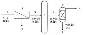
図2のプロセスでは、膜分離装置、蒸留塔、吸着装置を組合せて、上記エタノール水溶液からエタノールを回収する。スクラバーから排出されるエタノール水溶液1をエタノール選択透過膜を有する膜分離装置2へ導入し、エタノール濃度が高まった透過液5(エタノール濃度60〜90質量%)と排水4を得る。透過液5を蒸留塔7へ導入し、エタノール濃度85〜95質量%の留出液8を得る。留出液8は吸着装置9へ導入することにより
、脱水され、高濃度のエタノール6(エタノール濃度99質量%以上)を回収することができる。
In the process of FIG. 2, ethanol is recovered from the aqueous ethanol solution by combining a membrane separation device, a distillation column, and an adsorption device. The
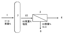
図3のプロセスでは、蒸留塔、膜分離装置を組合せて、上記エタノール水溶液からエタノールを回収する。スクラバーから排出されるエタノール水溶液1を蒸留塔7へ導入して、エタノール濃度85質量%程度の留出液10を得る。留出液10を水選択透過膜を有する膜分離装置3へ導入して、高濃度のエタノール6(エタノール濃度99質量%以上)を回収することができる。
In the process of FIG. 3, ethanol is recovered from the ethanol aqueous solution by combining a distillation column and a membrane separator. The
1.エタノール水溶液
2.エタノール選択透過膜を有する膜分離装置
3.水選択透過膜を有する膜分離装置
4.排水
5.透過液
6.エタノール
7.蒸留塔
8.留出液
9.吸着装置
10.留出液
1. 1.
Claims (7)
Priority Applications (1)
| Application Number | Priority Date | Filing Date | Title |
|---|---|---|---|
| JP2016062094A JP6816372B2 (en) | 2016-03-25 | 2016-03-25 | How to recover ethanol |
Applications Claiming Priority (1)
| Application Number | Priority Date | Filing Date | Title |
|---|---|---|---|
| JP2016062094A JP6816372B2 (en) | 2016-03-25 | 2016-03-25 | How to recover ethanol |
Publications (2)
| Publication Number | Publication Date |
|---|---|
| JP2017171631A true JP2017171631A (en) | 2017-09-28 |
| JP6816372B2 JP6816372B2 (en) | 2021-01-20 |
Family
ID=59971756
Family Applications (1)
| Application Number | Title | Priority Date | Filing Date |
|---|---|---|---|
| JP2016062094A Active JP6816372B2 (en) | 2016-03-25 | 2016-03-25 | How to recover ethanol |
Country Status (1)
| Country | Link |
|---|---|
| JP (1) | JP6816372B2 (en) |
Cited By (2)
| Publication number | Priority date | Publication date | Assignee | Title |
|---|---|---|---|---|
| KR102116878B1 (en) * | 2020-01-30 | 2020-05-29 | (주)세프라텍 | equipment and method of production high concentration bio alcohol using a pervaporation and distillation |
| CN116764398A (en) * | 2023-08-18 | 2023-09-19 | 中国华能集团清洁能源技术研究院有限公司 | Carbon dioxide dehydration drying system and process |
Citations (12)
| Publication number | Priority date | Publication date | Assignee | Title |
|---|---|---|---|---|
| JPS55120791A (en) * | 1979-02-27 | 1980-09-17 | Alfa Laval Ab | Ethanol making method |
| JPS6211088A (en) * | 1985-07-08 | 1987-01-20 | Hitachi Zosen Corp | Method of concentrating alcohol |
| JPS62223138A (en) * | 1986-01-17 | 1987-10-01 | ユナイティド ディスティラーズ パブリック リミティド カンパニー | Method and apparatus for removing water from ethanol mixture |
| JPH01155928A (en) * | 1987-12-10 | 1989-06-19 | Hitachi Zosen Corp | Concentration and dehydration device for organic substance-water mixed solution |
| JP2006263561A (en) * | 2005-03-23 | 2006-10-05 | Mitsui Eng & Shipbuild Co Ltd | Distillation-membrane separation hybrid apparatus and separation method in which distillation and membrane separation are combined |
| JP2007275690A (en) * | 2006-04-03 | 2007-10-25 | Ngk Insulators Ltd | Method for separating and recovering organic liquid from organic liquid aqueous solution |
| JP2010207776A (en) * | 2009-03-12 | 2010-09-24 | Hiroshima Univ | Organic acid hardly adsorbable porous body and method of selectively separating alcohol |
| JP2011121045A (en) * | 2009-11-11 | 2011-06-23 | Mitsubishi Chemicals Corp | Method and apparatus for separating water-containing organic compound |
| JP2012080824A (en) * | 2010-10-12 | 2012-04-26 | Actree Corp | Device for producing ethanol and production method using the same |
| JP2013521828A (en) * | 2010-03-19 | 2013-06-13 | バックマン・ラボラトリーズ・インターナショナル・インコーポレーテッド | Processes using antibiotic substitutes in bioethanol production |
| JP2015501643A (en) * | 2011-12-09 | 2015-01-19 | ビュータマックス・アドバンスド・バイオフューエルズ・エルエルシー | Method for removing product alcohol from fermentation broth |
| JP2016010404A (en) * | 2006-10-26 | 2016-01-21 | キシレコ インコーポレイテッド | Method of processing biomass |
-
2016
- 2016-03-25 JP JP2016062094A patent/JP6816372B2/en active Active
Patent Citations (12)
| Publication number | Priority date | Publication date | Assignee | Title |
|---|---|---|---|---|
| JPS55120791A (en) * | 1979-02-27 | 1980-09-17 | Alfa Laval Ab | Ethanol making method |
| JPS6211088A (en) * | 1985-07-08 | 1987-01-20 | Hitachi Zosen Corp | Method of concentrating alcohol |
| JPS62223138A (en) * | 1986-01-17 | 1987-10-01 | ユナイティド ディスティラーズ パブリック リミティド カンパニー | Method and apparatus for removing water from ethanol mixture |
| JPH01155928A (en) * | 1987-12-10 | 1989-06-19 | Hitachi Zosen Corp | Concentration and dehydration device for organic substance-water mixed solution |
| JP2006263561A (en) * | 2005-03-23 | 2006-10-05 | Mitsui Eng & Shipbuild Co Ltd | Distillation-membrane separation hybrid apparatus and separation method in which distillation and membrane separation are combined |
| JP2007275690A (en) * | 2006-04-03 | 2007-10-25 | Ngk Insulators Ltd | Method for separating and recovering organic liquid from organic liquid aqueous solution |
| JP2016010404A (en) * | 2006-10-26 | 2016-01-21 | キシレコ インコーポレイテッド | Method of processing biomass |
| JP2010207776A (en) * | 2009-03-12 | 2010-09-24 | Hiroshima Univ | Organic acid hardly adsorbable porous body and method of selectively separating alcohol |
| JP2011121045A (en) * | 2009-11-11 | 2011-06-23 | Mitsubishi Chemicals Corp | Method and apparatus for separating water-containing organic compound |
| JP2013521828A (en) * | 2010-03-19 | 2013-06-13 | バックマン・ラボラトリーズ・インターナショナル・インコーポレーテッド | Processes using antibiotic substitutes in bioethanol production |
| JP2012080824A (en) * | 2010-10-12 | 2012-04-26 | Actree Corp | Device for producing ethanol and production method using the same |
| JP2015501643A (en) * | 2011-12-09 | 2015-01-19 | ビュータマックス・アドバンスド・バイオフューエルズ・エルエルシー | Method for removing product alcohol from fermentation broth |
Non-Patent Citations (1)
| Title |
|---|
| 岡部和弘 , 湯塩泰久, 細谷俊史, 金澤進一, 柏原秀樹 , 中井龍資: "ゼオライト膜を用いたバイオエタノールの濃縮脱水プロセスの経済性評価", 化学工学論文集, vol. 36, no. 5, JPN7020000239, 2010, pages 486 - 493, ISSN: 0004203051 * |
Cited By (3)
| Publication number | Priority date | Publication date | Assignee | Title |
|---|---|---|---|---|
| KR102116878B1 (en) * | 2020-01-30 | 2020-05-29 | (주)세프라텍 | equipment and method of production high concentration bio alcohol using a pervaporation and distillation |
| WO2021153848A1 (en) * | 2020-01-30 | 2021-08-05 | 주식회사 세프라텍 | Facility and method for producing high-concentration bio-alcohol using pervaporation and distillation processes |
| CN116764398A (en) * | 2023-08-18 | 2023-09-19 | 中国华能集团清洁能源技术研究院有限公司 | Carbon dioxide dehydration drying system and process |
Also Published As
| Publication number | Publication date |
|---|---|
| JP6816372B2 (en) | 2021-01-20 |
Similar Documents
| Publication | Publication Date | Title |
|---|---|---|
| Kujawska et al. | ABE fermentation products recovery methods—a review | |
| US7732173B2 (en) | Ethanol recovery process | |
| Vane | Separation technologies for the recovery and dehydration of alcohols from fermentation broths | |
| US10836694B2 (en) | Method for producing high concentration alcohol | |
| Vane | A review of pervaporation for product recovery from biomass fermentation processes | |
| US8628642B2 (en) | Processing plant for performing membrane-based hybrid process for separation of mixtures of organics, solids, and water | |
| Kang et al. | Hydrophilic membranes to replace molecular sieves in dewatering the bio-ethanol/water azeotropic mixture | |
| Kang et al. | Hybrid operation of the bio-ethanol fermentation | |
| Van der Bruggen et al. | Pervaporation | |
| Strathmann et al. | Continuous removal of ethanol from bioreactor by pervaporation | |
| JP2020075864A (en) | Method for producing alcohol | |
| Yu et al. | Very high flux MFI membranes for alcohol recovery via pervaporation at high temperature and pressure | |
| Cai et al. | Separation of butanol, acetone, and ethanol | |
| JP6816372B2 (en) | How to recover ethanol | |
| WO2018168978A1 (en) | Water-alcohol separation system and water-alcohol separation method for producing alcohol | |
| US20090239288A1 (en) | Integrated membrane separation - bioreactor for selective removal of organic products and by-products | |
| Gonçalves et al. | Developments in downstream butanol separation from acetone, butanol, and ethanol fermentation | |
| JP2017165671A (en) | Method for producing high-concentration alcohol | |
| JP2018020985A (en) | Process for producing alcohol | |
| Huang et al. | Separation and purification processes for lignocellulose-to-bioalcohol production | |
| EP3679150B1 (en) | Method and apparatus for in situ product recovery | |
| JP5897130B2 (en) | Alcohol purification apparatus and alcohol purification method | |
| Izquierdo‐Gil | Membrane distillation | |
| Bello et al. | Effect of operating variables on the pervaporation of ethanol produced by lignocellulosic residue | |
| KR20120084822A (en) | Efficient method of recovery, concentration, and dehydration of low-concentrated biochemical |
Legal Events
| Date | Code | Title | Description |
|---|---|---|---|
| A711 | Notification of change in applicant |
Free format text: JAPANESE INTERMEDIATE CODE: A712 Effective date: 20170421 |
|
| A621 | Written request for application examination |
Free format text: JAPANESE INTERMEDIATE CODE: A621 Effective date: 20190314 |
|
| A977 | Report on retrieval |
Free format text: JAPANESE INTERMEDIATE CODE: A971007 Effective date: 20200114 |
|
| A131 | Notification of reasons for refusal |
Free format text: JAPANESE INTERMEDIATE CODE: A131 Effective date: 20200204 |
|
| A601 | Written request for extension of time |
Free format text: JAPANESE INTERMEDIATE CODE: A601 Effective date: 20200327 |
|
| A521 | Request for written amendment filed |
Free format text: JAPANESE INTERMEDIATE CODE: A523 Effective date: 20200603 |
|
| A521 | Request for written amendment filed |
Free format text: JAPANESE INTERMEDIATE CODE: A523 Effective date: 20200604 |
|
| TRDD | Decision of grant or rejection written | ||
| A01 | Written decision to grant a patent or to grant a registration (utility model) |
Free format text: JAPANESE INTERMEDIATE CODE: A01 Effective date: 20201124 |
|
| A61 | First payment of annual fees (during grant procedure) |
Free format text: JAPANESE INTERMEDIATE CODE: A61 Effective date: 20201207 |
|
| R151 | Written notification of patent or utility model registration |
Ref document number: 6816372 Country of ref document: JP Free format text: JAPANESE INTERMEDIATE CODE: R151 |