JP2017171045A - Slide device for vehicle and rolling element circulation unit for slide device - Google Patents
Slide device for vehicle and rolling element circulation unit for slide device Download PDFInfo
- Publication number
- JP2017171045A JP2017171045A JP2016057653A JP2016057653A JP2017171045A JP 2017171045 A JP2017171045 A JP 2017171045A JP 2016057653 A JP2016057653 A JP 2016057653A JP 2016057653 A JP2016057653 A JP 2016057653A JP 2017171045 A JP2017171045 A JP 2017171045A
- Authority
- JP
- Japan
- Prior art keywords
- rolling
- annular
- annular housing
- rail
- rolling element
- Prior art date
- Legal status (The legal status is an assumption and is not a legal conclusion. Google has not performed a legal analysis and makes no representation as to the accuracy of the status listed.)
- Pending
Links
Images


Classifications
-
- B—PERFORMING OPERATIONS; TRANSPORTING
- B60—VEHICLES IN GENERAL
- B60N—SEATS SPECIALLY ADAPTED FOR VEHICLES; VEHICLE PASSENGER ACCOMMODATION NOT OTHERWISE PROVIDED FOR
- B60N2/00—Seats specially adapted for vehicles; Arrangement or mounting of seats in vehicles
- B60N2/02—Seats specially adapted for vehicles; Arrangement or mounting of seats in vehicles the seat or part thereof being movable, e.g. adjustable
- B60N2/04—Seats specially adapted for vehicles; Arrangement or mounting of seats in vehicles the seat or part thereof being movable, e.g. adjustable the whole seat being movable
- B60N2/06—Seats specially adapted for vehicles; Arrangement or mounting of seats in vehicles the seat or part thereof being movable, e.g. adjustable the whole seat being movable slidable
- B60N2/07—Slide construction
Landscapes
- Engineering & Computer Science (AREA)
- Aviation & Aerospace Engineering (AREA)
- Transportation (AREA)
- Mechanical Engineering (AREA)
- Seats For Vehicles (AREA)
Abstract
Description
本発明は、車両用スライド装置、及びスライド装置用転動体循環ユニットに関する。 The present invention relates to a slide device for a vehicle and a rolling element circulation unit for the slide device.
従来、車両用シートを前後方向に移動自在に支持する車両用スライド装置、及びそのスライド装置に用いられる転動体循環ユニットがある。例えば、特許文献1には、第1レール及び第2レールを有する車両用シートスライド装置において、第2レールに固定され複数の転動体をそれぞれ転動循環自在に環状に配置可能な一対の環状収容部を有している転動体循環ユニットを有する構成が記載されている。この構成によれば、転動体は、第1レールに設けられた作動面と、転動体循環ユニットの環状収容部に当接して環状収容部を転動循環することにより、第1レールと第2レールが相対移動し、円滑なスライド前後移動を可能にする。
2. Description of the Related Art Conventionally, there are a vehicle slide device that supports a vehicle seat movably in the front-rear direction, and a rolling element circulation unit used in the slide device. For example, in
特許文献1には、転動体循環ユニットは第1レール及び第2レールとの間に設けられ、転動体がそれぞれ転動循環可能に配置されている一対の環状収容部が、第1ケース及び第2ケースの対向面かつ同一面に設けられていることが記載されている。
In
しかしながら、特許文献1に開示される転動体循環ユニットは、第1レール及び第2レールの間に配置され、さらに、一対の環状収容部が同一面に形成されている。したがって、一対の環状収容部が設けられるスペースが限られてしまう。一対の環状収容部の形成スペースが限られているため、環状収容部の円弧部の大きさが十分に確保できない場合がある。したがって、環状収容部の円弧部が十分に確保できない場合、転動体が環状収容部を円滑に転動循環できないため、第1レールと第2レールとの円滑な相対移動ができないという懸念があった。
However, the rolling element circulation unit disclosed in
本発明はこうした事情に鑑みてなされたものであり、その目的は、転動体循環ユニットに環状収容部を形成する場合、転動体循環ユニットを大型化することなく、第1レールと第2レールとを円滑に相対移動させることができる車両用スライド装置、及びスライド装置用転動体循環ユニットを提供する。 This invention is made | formed in view of such a situation, The objective is, when forming an annular accommodating part in a rolling element circulation unit, without enlarging a rolling element circulation unit, a 1st rail and a 2nd rail Provided are a vehicle slide device and a rolling device circulation unit for the slide device that can smoothly move relative to each other.
上記の課題を解決するために、本発明の課題解決手段は、車両に設けられる第1レールと、前記第1レールの延在方向に相対的に移動自在に該第1レールに支持される第2レールと、第1及び第2環状収容部が設けられたハウジング部、並びに前記第1及び第2環状収容部内にそれぞれ収容される複数の転動体を有する転動体循環ユニットと、を備え、前記ハウジング部は、第1ケース部と、該第1ケース部に係合される第2ケース部及び第3ケース部とを有し、前記第1ケース部及び前記第2ケース部の対向面に前記第1環状収容部が前記転動体をそれぞれ転動循環自在に環状に配置可能にするように設けられるとともに、前記第1ケース部及び前記第3ケース部の対向面に前記第2環状収容部が前記転動体をそれぞれ転動循環自在に環状に配置可能にするように設けられ、前記第1及び第2環状収容部に収容された前記転動体が、前記第1レールに設けられた作動面と前記環状収容部とに当接し、該作動面と該環状収容部との間で転動移動することにより前記第1及び第2環状収容部内をそれぞれ転動循環する構造をなし、前記第1及び第2環状収容部は、前記転動体循環ユニットが前記第2レールに固定された状態における水平方向において互いに重なる位置関係となるように設けられることが望ましい。 In order to solve the above-described problems, the problem-solving means of the present invention includes a first rail provided in a vehicle and a first rail supported by the first rail so as to be relatively movable in the extending direction of the first rail. Two rolling elements, a housing part provided with first and second annular accommodating parts, and a rolling element circulation unit having a plurality of rolling elements respectively accommodated in the first and second annular accommodating parts, The housing portion includes a first case portion, and a second case portion and a third case portion that are engaged with the first case portion, and the housing portion has an opposing surface on the first case portion and the second case portion. A first annular housing portion is provided so as to allow the rolling elements to be arranged in an annular manner so as to be able to roll and circulate, respectively, and the second annular housing portion is provided on opposing surfaces of the first case portion and the third case portion. Each of the rolling elements is annular and can be circulated freely. The rolling elements, which are provided so as to be arranged and accommodated in the first and second annular accommodating portions, abut against the operating surface provided on the first rail and the annular accommodating portion, and the operating surface And the annular housing portion are configured to roll and circulate in the first and second annular housing portions respectively by rolling and moving between the annular housing portion and the first and second annular housing portions. Are preferably provided so as to overlap each other in the horizontal direction when fixed to the second rail.
上記構成によると、第1及び第2環状収容部は、転動体循環ユニットが第2レールに固定された状態における水平方向において互いに重なる位置関係となるため、該水平方向において互いに重ならないように形成されている場合に比べ、ハウジングの垂直方向への大きさを変更することなく、第1及び第2環状収容部の形成面が大きく確保できる。すなわち、ハウジングの大型化を要せずに第1及び第2環状収容部の円弧部を大きく設定することができる。よって、転動体循環ユニット、ひいては第1レール及び第2レールの大型化を要することなく、各転動体を各環状収容部内で円滑に転動循環させることができ、第1レールと第2レールとを円滑に相対移動させることができる。 According to the above configuration, the first and second annular housing portions are formed so as not to overlap each other in the horizontal direction because the rolling element circulation unit is in a positional relationship overlapping with each other in the horizontal direction in a state where the rolling element circulation unit is fixed to the second rail. Compared with the case where it is made, the formation surface of the 1st and 2nd annular accommodating part can be largely ensured, without changing the magnitude | size to the perpendicular direction of a housing. That is, the arc portions of the first and second annular housing portions can be set large without requiring an increase in the size of the housing. Therefore, each rolling element can be smoothly rolled and circulated in each annular housing portion without requiring an increase in the size of the rolling element circulation unit, and thus the first rail and the second rail, and the first rail and the second rail. Can be moved relative to each other smoothly.
また、本発明の課題解決手段として、前記第1及び第2環状収容部は、前記転動体循環ユニットが前記第2レールに固定された状態における垂直方向においても互いに重なる位置関係となるように設けられることが好ましい。 Further, as a means for solving the problems of the present invention, the first and second annular accommodating portions are provided so as to overlap each other even in a vertical direction in a state where the rolling element circulation unit is fixed to the second rail. It is preferred that
上記構成によれば、第1及び第2環状収容部は、転動体循環ユニットが第2レールに固定された状態における垂直方向において互いに重なる位置関係となるため、該垂直方向において互いに重ならないように形成されている場合に比べ、ハウジングの水平方向への大きさを変更することなく、第1及び第2環状収容部の形成面が大きく確保できる。 According to the above configuration, the first and second annular housing portions are in a positional relationship in which the rolling element circulation units overlap with each other in the vertical direction in a state where the rolling element circulation unit is fixed to the second rail, so that they do not overlap with each other in the vertical direction. Compared with the case where it is formed, a large formation surface of the first and second annular housing portions can be secured without changing the size of the housing in the horizontal direction.
また、本発明の課題解決手段として、前記転動体は、第1の直径でかつ金属材料によって形成された第1球体と、第1の直径よりも小径である第2の直径でかつ樹脂材料によって形成された第2球体とを含んで構成され、かつ、前記第1及び第2環状収容部において前記第1球体及び第2球体がそれぞれ交互になるように配置されていることが好ましい。 Moreover, as a problem-solving means of the present invention, the rolling element has a first sphere formed of a metal material with a first diameter, and a second diameter smaller than the first diameter and a resin material. Preferably, the first sphere and the second sphere are alternately arranged in the first and second annular housing portions.
上記構成によれば、第1の直径の金属製球体と、該金属製球体よりも小さい直径である樹脂製球体が環状収容部に交互に配置されている。樹脂製球体が金属製球体よりも小さい直径であることから、樹脂製球体が環状収容部及び作動面との摩擦を抑制することができ、樹脂製球体の摩耗による変形を抑制することができる。 According to the above configuration, the metal spheres having the first diameter and the resin spheres having a smaller diameter than the metal spheres are alternately arranged in the annular housing portion. Since the resin sphere has a smaller diameter than the metal sphere, the resin sphere can suppress friction between the annular housing portion and the operating surface, and deformation due to wear of the resin sphere can be suppressed.
また、本発明の課題解決手段として、前記第1及び第2環状収容部は、前記転動体を介して前記作動面に当接する当接面と、前記転動体を介して前記作動面と当接しない非当接面とを有し、前記当接面は前記非当接面よりも大きい剛性を有していることが好ましい。 Further, as means for solving the problems of the present invention, the first and second annular accommodating portions are in contact with the operating surface via the rolling element, and are in contact with the operating surface via the rolling element. It is preferable that the contact surface has a rigidity higher than that of the non-contact surface.
上記構成によれば、第1レールと第2レールとの間に備えられている転動体循環ユニットの環状収容部における当接面は、転動体を介して第1レールの作動面に当接している。すなわち、当接面は、第1レールからの荷重を転動体を介して受承している。当接面を構成する部位は、第1レールからの荷重を受けない非当接面を構成する部位よりも高い剛性を有する材料によって形成されている。これより、当接面は、第1レールから転動体を介して加わる荷重を十分に受承することができるため、環状収容部の耐久性低下を抑制することができる。 According to the above configuration, the contact surface in the annular housing portion of the rolling element circulation unit provided between the first rail and the second rail is in contact with the operating surface of the first rail via the rolling element. Yes. That is, the contact surface receives the load from the first rail via the rolling elements. The part constituting the contact surface is formed of a material having higher rigidity than the part constituting the non-contact surface that does not receive a load from the first rail. As a result, the contact surface can sufficiently receive the load applied from the first rail via the rolling elements, and therefore, it is possible to suppress a decrease in durability of the annular housing portion.
また、本発明の課題解決手段として、第1及び第2環状収容部が設けられたハウジング部、並びに前記第1及び第2環状収容部内にそれぞれ収容される複数の転動体を有する転動体循環ユニットと、を備え、前記ハウジング部は、第1ケースと、該第1ケースに係合される第2ケース及び第3ケースとを有し、前記第1ケース及び前記第2ケースの対向面に前記第1環状収容部が前記転動体をそれぞれ転動循環自在に環状に配置可能にするように設けられるとともに、前記第1ケース及び前記第3ケースの対向面に前記第2環状収容部が前記転動体をそれぞれ転動循環自在に環状に配置可能にするように設けられ、前記第1及び第2環状収容部に収容された前記転動体が、前記第1レールに設けられた作動面と前記環状収容部とに当接し、該作動面と該環状収容部との間で転動移動することにより前記第1及び第2環状収容部内をそれぞれ転動循環する構造をなし、前記第1及び第2環状収容部は、前記転動体循環ユニットが前記第2レールに固定された状態における水平方向において互いに重なる位置関係となるように設けられるスライド装置用転動体ユニットであることが好ましい。 Further, as means for solving the problems of the present invention, a rolling element circulation unit having a housing part provided with first and second annular accommodating parts and a plurality of rolling elements respectively accommodated in the first and second annular accommodating parts. And the housing part includes a first case, and a second case and a third case engaged with the first case, and the housing portion is provided on an opposing surface of the first case and the second case. A first annular housing portion is provided so that the rolling elements can be annularly arranged so as to be capable of rolling and circulating, respectively, and the second annular housing portion is disposed on the opposing surfaces of the first case and the third case. The rolling elements are provided so as to be arranged in an annular shape so as to be capable of rolling and circulating, respectively, and the rolling elements accommodated in the first and second annular accommodating portions are connected to the operating surface provided on the first rail and the annular shape. Abutting against the housing part, The first and second annular housing portions are configured to circulate and circulate in the first and second annular housing portions by rolling between the moving surface and the annular housing portion, respectively. It is preferable that the circulation unit is a rolling device unit for a slide device that is provided so as to overlap with each other in the horizontal direction when the circulation unit is fixed to the second rail.
本発明によれば、転動体循環ユニットを大型化することなく、各転動体を各環状収容部内で円滑に転動循環させることができ、第1レールと第2レールとを円滑に相対移動させることができる。 According to the present invention, each rolling element can be smoothly rolled and circulated within each annular housing portion without increasing the size of the rolling element circulation unit, and the first rail and the second rail can be relatively moved relative to each other. be able to.
以下、本発明を具体化した一実施形態を図に従って説明する。 Hereinafter, an embodiment embodying the present invention will be described with reference to the drawings.
(車両用シート全体)
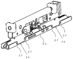
図1に示すように、車両用スライド装置は、車両のフロア1の前後方向に固定される左右一対のロアレール(本願発明「第1レール」)10と、車両のシート2に固定され、ロアレール10に対し相対移動自在に支持される左右一対のアッパレール(本願発明「第2レール」)20を有している。また、図2に示すように、アッパレール20をロアレール10に対しスムーズにかつガタ無く移動させるため、アッパレール20とロアレール10との間に転動体循環ユニット40が設けられている。
(Whole vehicle seat)
As shown in FIG. 1, the vehicle slide device is fixed to a pair of left and right lower rails (the “first rail” of the present invention) 10 fixed in the front-rear direction of a
(ロアレールの構成)
図2に示すように、ロアレール10は、車両のフロア1に水平な基底部11と、基底部11の両端からそれぞれ上方に延びる側部12と、両側部12における下端にはそれぞれ内方に傾斜して基底部11に接続すされる傾斜部13と、両側部12の上端から内方に車両のフロア1に水平に延びる水平部14と、水平部14から下方に延びる垂下部15とを有している。転動体100が当接する両側部12及び両傾斜部13の内側面が作動面16に設定されている。
(Configuration of lower rail)
As shown in FIG. 2, the
(アッパレールの構成)
図2に示すように、アッパレール20は、第1レール片20aと第2レール片20bとを備えている。第1レール片20aは、車両のフロア1に対して水平な基盤部21と、該基盤部21における両レール片20a、20bとが対向していない側の一端から上方に延びる側壁22と、該基盤部21における両レール片20a、20bとが対向していない側の他端から上方に延びる起立部23と、該起立部23から上方の内方向に延びる連結部24とを有している。第2レール片20bは、第1レール片20aと同様に、基盤部21と、側壁22と、起立部23と、連結部24を有している。第1レール片20aと第2レール片20bの互いの連結部24が重ね合わせられることにより、両起立部23に包囲された空間Cを有するアッパレール20が構成されている。両側壁部22のロアレール10に対向する面が非作動面25として設定されている。該非作動面25は、ロアレール10に設けている作動面16と対向するように構成されている。
(Upper rail configuration)
As shown in FIG. 2, the
また、図3に示すように、アッパレール20の両側壁部22の長手方向の両端の近傍には、それぞれ転動体循環ユニット40が取着される取着部26が設けられている。各取着部26は、転動体循環ユニット40が取着される穴部27が2箇所ずつ設けられている。該取着部26は、両レール片20a、20bに設けられている両非作動面25を略矩形形状に切り取られるように設けられている。図4に示すように、転動体循環ユニット40が穴部27に取着されることによって、本実施形態におけるアッパレール20には、4つの転動体循環ユニット40が取着されている。なお、転動体循環ユニット40の個数は、両レールの長さ等によって必要であれば適宜変更されてもよい。
Further, as shown in FIG. 3,
(転動体循環ユニット)
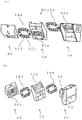
図5(a)及び(b)に示すように、転動体循環ユニット40は、ボディ50(本願発明「第1ケース」)と、該ボディ50に係合して組み付けられるカバー60(本願発明「第2ケース」)を備えている。さらに、ボディ50において、カバー60が組み付けられている側と逆側と対向する面に、ベース70(本願発明「第3ケース」)が係合して組み付けられている。ボディ50においてカバー60と対向する面には、複数の転動体100が転動循環する第1環状収容部41を構成する第1環状収容路41aが設けられている。また、該第1環状収容路41aに伴い、カバー60のボディ50と対向する面には、第1環状収容部41を構成する第1環状収容溝41bが設けられている。すなわち、該第1環状収容路41a及び該第1環状収容溝41bが対向し空間が形成されることにより、複数の転動体100が転動循環する第1環状収容部41が構成されている。さらに、ボディ50においてベース70と対向する面には、複数の転動体100を転動循環自在に収容する第2環状収容路42を構成する第2環状収容路42aが形成されている。該第2環状収容路42aに伴い、ボディ50のベース70に対向する面には、第2環状収容溝42bが設けられている。ここで、該第2環状収容路42a及び該第2環状収容溝42bが対向し空間が形成されることにより、複数の転動体100が転動循環する第2環状収容部42が構成されている。第1環状収容路41及び第2環状収容路42は、それぞれ略楕円状に形成されている。なお、ボディ50、カバー60及びベース70は、例えば、接着剤や嵌合構造などにより互いに係合可能に構成されている。
(Rolling body circulation unit)
As shown in FIGS. 5A and 5B, the rolling
図6(a)及び(b)に示すように、ボディ50は、第1ボディ51と、第2ボディ56から構成されている。
As shown in FIGS. 6A and 6B, the
第1ボディ51は、図6(a)に示すように、カバー60に対向する面と、ベース70の対向する面を有している。第1ボディ51は、第2ボディ56が組付けられるように、略U字形状に形成されている。第1ボディ51のカバー60と対向する面に、第1環状収容路41aの一部である第1非当接面52が形成されている。第1非当接面52は、転動体100を介してロアレール10の作動面16と当接しない。さらに、第1ボディ51には、ビス等(図示しない)を挿入することにより、第1ボディ51、カバー60及び第1ベース71を係合させることが可能な、第1挿入孔53が形成されている。該第1挿入孔53は、第1ボディ51を貫通するように設けられている。
As shown in FIG. 6A, the first body 51 has a surface facing the
また、第1ボディ51は、図6(b)に示すように、ベース70と対向する面に、第2環状収容溝42bが形成されている。さらに、第1ボディ51の端部には、第2環状収容路42aに収容された転動体100が、ロアレール10の作動面16と当接するため、転動体100と作動面16との間の第1ボディ51に開口するよう、切り欠き54が設けられている。また、第1ボディ51は、ベース70に対向する面において、第1挿入孔53の両側には、第1ベース71に設けられている一対の第2係止片76を係合させるための一対の第2係止孔55が設けられている。
In addition, as shown in FIG. 6B, the first body 51 has a second annular housing groove 42 b formed on the surface facing the
また、第2ボディ56は、図6(a)に示すように、第1ボディ51が略U字形状に形成されている端部間に組み付けられるような四角形状によって形成されている。第2ボディ52のカバー60と対向する面には、第1環状収容路41aの一部である第1当接面57が形成されている。該第1当接面57は、転動体100を介してロアレール10の作動面16と当接する。すなわち、第1ボディ51に形成されている第1非当接面52及び第2ボディ56に形成されている第1当接面57が連結されることより、第1環状収容路41aが形成されている。さらに、第2ボディ56には、カバー60及びベース70と係合させるためのビス等(図示しない)が挿入する第1挿通孔58が設けられている。該第1挿通孔58は、第2ボディ56を貫通するように形成されている。さらに、該第1挿通孔58の両側には、カバー60に設けられている一対の第1係止孔62が係止するための一対の第1係止片59が設けられている。
Further, as shown in FIG. 6A, the
ここで、第1ボディ51は、樹脂製の材料によって形成され、第2ボディ56は、金属製の材料によって形成されている。第2ボディ56には、ロアレール10の作動面16と転動体100を介して当接する第1当接面57が形成されているため、第1ボディ51よりも剛性が高い材料によって形成されていることが好ましい。第1ボディ51は、ロアレール10の作動面16と転動体100を介して当接することがないため、第2ボディ56よりも剛性が低い材料である、例えば、樹脂製の材料であってもよい。
Here, the first body 51 is formed of a resin material, and the
次に、カバー60は、図6(a)及び(b)に示すように、ボディ50に対向する面を有している。カバー60のボディ50に対向する面には、第1環状収容溝41bが設けられている。また、図6(a)に示すように、カバー60は、カバー60のロアレール10の作動面16及びロアレール10の傾斜部13の形状に合わせた第1傾斜面64及び第2傾斜面65が形成されている。図6(b)に示すように、カバー60のボディ50と対向する面において、該第1環状収容溝41bの内周側の中央には、ボディ50及びベース70を係合させるためのビス等(図示しない)を挿通する第2挿通孔61が設けられている。第2挿通孔61は、カバー60を貫通するように設けられている。さらに、カバー60のボディ50に対向する面において、第2挿通孔61の両側には第2ボディ56に構成されている一対の第1係止片59を係合させるための第1係止孔62が設けられている。さらに、カバー60のボディ50に対向する面において、第1環状収容溝41bには、長孔63が形成されている。該長孔63は、第1傾斜面64に貫通するように形成されている。また、該長孔63は、転動体100の直径よりも幅狭に設定されており、第1環状収容溝41bから各転動体100が抜け出さないようになっている。また、長孔63は、長手方向の両端部位が湾曲しつつ、中央部位が長手方向に沿って略直線状に延びる形状をなしている。すなわち、該長孔63によって、転動体100がカバー60から露出することにより、ロアレール10の作動面16に接することができる。さらに、第2傾斜面65の端部には、ボディ50及びベース70を係合させるためのビス等(図示しない)を挿通させる第2挿入孔66が形成されている。
Next, as shown in FIGS. 6A and 6B, the
次に、ベース70は、図6(a)及び(b)に示すように、第1ベース71と、第2ベース80から構成されている。
Next, as shown in FIGS. 6A and 6B, the
第1ベース71は、図6(a)に示すように、底部72と、底部72の両端側に壁部73を備えている。底部72には、第2環状収容路42aの一部を形成する第2当接面74が設けられている。第2環状収容路42aを形成する同一面に、ボディ50及びカバー60を係合させるためのビス等(図示しない)を挿通する第3挿入孔75が設けられている。該第3挿入孔75は、第1ベース71を貫通するように設けられている。第3挿入孔75の両側には、第1ボディ51に形成されている第2係止孔55に係合させることにより、第1ボディ51及び第1ベース71を一体構成させることが可能な第2係止片76が設けられている。また、底部72には、ボディ50及びカバー60を係合させるためのビス等(図示しない)を挿通させる第3挿通孔77が形成されている。さらに、両壁部73には、延出するフランジ部78が設けられている。両フランジ部78には、アッパレール20の穴部27に対して例えばビス等が挿通することによって固定可能となる貫通孔79が形成されている。
As shown in FIG. 6A, the
第2ベース80は、図6(a)に示すように、第1ベース71の設けられている第2当接面74に係合させることが可能な略U字型形状を成している。第2ベース80のボディ50と対向する面には、第2環状収容路42aの一部を成す第2非当接面81が設けられている。該第2非当接面81は、転動体100を介してロアレール10の作動面16に当接する。第2非当接面81及び第2当接面74が連結することにより、ベース70における第2環状収容路42aが形成される。
As shown in FIG. 6A, the
ここで、第2当接面74が設けられる第1ベース71は金属材料によって構成され、第2非当接面81が設けられる第2ベース80は樹脂材料によって構成されていることが好ましい。第2ベース80は、ロアレール10の作動面16と転動体100を介して当接することがないため、第1ベース71よりも剛性が低い材料である樹脂製であってもよい。
Here, it is preferable that the
本実施形態において、転動体100は、金属材料によって形成されている金属製球体101(本願発明「第1球体」)及び樹脂材料によって形成されている樹脂製球体102(本願発明 「第2球体」)から構成されている。該金属製球体101は直径R1とし、該樹脂製球体102の直径はR2とし、「R1>R2」が成立するように、金属製球体101及び樹脂製球体102が設けられている。なお、図5(a)及び(b)においては、樹脂製球体102をハッチングにて示す。さらに、図5(a)及び(b)に示すように、第1環状収容路41a及び第2環状収容路42a内には、金属製球体101及び樹脂製球体102がそれぞれ交互に配置されている。転動体循環ユニット40は、第1環状収容路41a及び第2環状収容路42aに転動体100を収容し、ボディ50、カバー60及びベース70に係合することにより一体構成されている。
In this embodiment, the rolling
図7に示すように、転動体循環ユニット40は、第1環状収容路41a及び第1環状収容溝41bに収容された各転動体100が第1ボディ51の切り欠き部54から露出するように構成されている。また、第2環状収容路42a及び第2環状収容溝41bに収容されている各転動体100がカバー60の長孔63から露出するように構成されている。
As shown in FIG. 7, the rolling
図3及び図4に示すように、アッパレール20の取着部26の穴部27と、転動体循環ユニット40の第1ベース71のフランジ部78に設けられている貫通孔79とをビス等(図示なし)を挿通させることによって固定される。
As shown in FIGS. 3 and 4, the
図8には、転動体循環ユニット40がアッパレール20に取着され、ロアレール10の作動面16に対して転動体100が当接するように組み付けられている状態の断面図を示す。図8に示すように、第1環状収容部41及び第2環状収容部42は、水平方向及び垂直方向において互いに重なる位置関係となるように設けられている。第1ボディ51において、第1環状収容路41a及び第2環状収容溝42bが、カバー60及びベース70に対向する面にそれぞれ互いに重なるように形成されている。すなわち、転動体循環ユニット40がアッパレール20に組み付けられている状態において、転動体100が、水平方向及び垂直方向において互いに重なる位置関係となっている。
FIG. 8 shows a cross-sectional view of a state in which the rolling
(車両用スライド装置の動作)
次に、本実施形態における車両用スライド装置の動作について説明する。
(Operation of vehicle sliding device)
Next, the operation of the vehicle slide device according to the present embodiment will be described.
図8に示すように、転動体循環ユニット40は、アッパレール20の取着部26に取着されると、第1環状収容部41に収容されている転動体100は、第2ボディ56の第1当接面57に当接しながら、ロアレール10の作動面16に接する。また、第2環状収容部42に収容されている転動体100は、第1ベース71の第2当接面74に当接しながら、ロアレール10の作動面16に接する。
As shown in FIG. 8, when the rolling
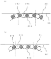
ここで、図9(a)及び(b)に示すように、転動体100が作動面16に当接する際、転動体100は作動面16に対して5個対面するように第1環状収容部41及び第2環状収容部42が形成されている。図9(a)は、転動体100が作動面16に当接する際、金属製球体101が2個、樹脂製球体102が3個ずつそれぞれ対面する場合を表す。さらに、図9(b)は、ロアレール10がアッパレール20に対してスライド移動した場合を示す。すなわち、転動体100が作動面16に当接する際、金属製球体101が3個、樹脂製球体102が2個ずつそれぞれ対面する場合を示す。したがって、作動面16に対して、金属製球体101が少なくとも2個はかならず対面するようになっている。
Here, as shown in FIGS. 9A and 9B, when the rolling
ロアレール10に対しアッパレール20がスライド移動すると、作動面16及び第1当接面57、並びに作動面16及び第2当接面74にそれぞれ接するとともに、第1環状収容部41及び第2環状収容部42にそれぞれ収容された各転動体100が転動しながら循環する。
When the
以上、本実施形態によれば、以下のような効果を得ることができる。 As described above, according to the present embodiment, the following effects can be obtained.
(1)本実施形態によれば、転動体循環ユニット40の第2ボディ56のカバー60及びベース70に対向する面において、転動体循環ユニット40がアッパレール20に取着された状態における第1環状収容部41及び第2環状収容部42が、水平方向において互いに重なる位置関係となるため、第1環状収容路41a及び第1環状収容溝41b、並びに第2環状収容路42a及び第2環状収容溝41bの形成面の大きさが、転動体循環ユニット40を水平方向に大型化することなく、大きく確保できる。
(1) According to this embodiment, the first annular shape in a state where the rolling
(2)本実施形態によれば、第1環状収容路41a及び第1環状収容溝41b、並びに第2環状収容路42a及び第2環状収容溝42bの形成面が大きく確保できる。すなわち、各環状収容路及び環状収容溝の円弧部を大きく設定することができる。これより、転動体100が円弧部を転動循環する際、転動体100が転動循環する速さを緩める必要が少なくなるため、転動体100が第1環状収容部41及び第2環状収容部42を円滑に転動循環させることができる。すなわち、ロアレール10及びアッパレール20が円滑に相対移動させることができる。
(2) According to the present embodiment, it is possible to ensure a large formation surface of the first annular housing passage 41a and the first annular housing groove 41b, and the second annular housing passage 42a and the second annular housing groove 42b. That is, the circular arc part of each annular accommodating path and the annular accommodating groove can be set large. Accordingly, when the rolling
(3)本実施形態によれば、第1環状収容路41a及び第1環状収容溝41b、並びに第2環状収容路42a及び第2環状収容溝42bの形成面が大きく確保できる。各転動体100が接触する作動面16に対して、各転動体100が非接触状態から接触状態となる際の進入角度を小さくさせ、各転動体100を作動面に対して徐々に接触させることにより、転動体100が第1環状収容部41及び第2環状収容部42aを転動循環する際の転動体100及び作動面16の当接音による異音の発生を抑制することができる。
(3) According to the present embodiment, it is possible to ensure a large formation surface of the first annular housing passage 41a and the first annular housing groove 41b, and the second annular housing passage 42a and the second annular housing groove 42b. The approach angle when each rolling
(4)本実施形態によれば、第1環状収容路41a及び第1環状収容溝41b、並びに第2環状収容路42a及び第2環状収容溝42bを水平方向及び垂直方向に互いに重なるように配置されている。これより、転動体循環ユニット40が水平方向及び垂直方向への大型化を抑制することができる。
(4) According to this embodiment, the first annular housing passage 41a and the first annular housing groove 41b, and the second annular housing passage 42a and the second annular housing groove 42b are arranged so as to overlap each other in the horizontal direction and the vertical direction. Has been. Thereby, the rolling
(5)本実施形態によれば、第1環状収容路41aの第1当接面57及び第2環状収容路42aの第2当接面74が金属材料によって構成されている。また、第1環状収容路41aの第1非当接面52及び第2環状収容路42aの第2非当接面81は樹脂材料によって構成されている。第1当接面57及び第2当接面74は、ロアレール10からの荷重を転動体100を介して受承している。一方、第1非当接面52及び第2非当接面81は、ロアレール10からの荷重を受承しない。これより、第1当接面57及び第2当接面74を第1非当接面52及び第2非当接面81よりも高い剛性を有する金属材料によって形成することにより、ロアレール10からの荷重を十分に受承することができ、転動体循環ユニット40の耐久性の低下を抑制することができる。
(5) According to the present embodiment, the
(6)本実施形態によれば、第1非当接面52及び第2非当接面81を第1当接面57及び第2当接面74よりも低い剛性を有する樹脂材料によって構成する。これより、転動体100が第1非当接面52及び第2非当接面81と当接する衝撃を緩和することができることから、転動体100が第1環状収容路41a及び第2環状収容路42aを転動循環する際の当接音による異音の発生を抑制させることができる。
(6) According to the present embodiment, the first non-contact surface 52 and the second non-contact surface 81 are made of a resin material having lower rigidity than the
(7)本実施形態によれば、転動体循環ユニット40第2ボディ56及び第1ベース71のみを金属材料によって形成し、その他部分を樹脂材料によって形成している。これより、転動体循環ユニット40をすべて金属材料によって形成する場合よりも軽量化することができる。
(7) According to this embodiment, only the rolling
(8)本実施形態によれば、転動体100は、金属製球体101と樹脂製球体102により構成され、金属製球体101は樹脂製球体102よりも大きい直径で形成されている。この構成によれば、転動体100は第1環状収容路41a及び第2環状収容路42aを転動循環する際に、金属製球体101よりも樹脂製球体102の方が第1環状収容路41a及び第2環状収容路42aとの摩擦力が少なくなるため、転動体100がすべて金属製球体101によって形成されている場合に比べ、転動体100が第1環状収容路41a及び第2環状収容路42aを転動循環する際の当接音による異音の発生を抑制させることができる。
(8) According to this embodiment, the rolling
(9)本実施形態によれば、転動体100は、金属製球体101と樹脂製球体102により構成され、金属製球体101は樹脂製球体102よりも大きい直径で形成されている。これにより、転動体100が第1環状収容路41a及び第2環状収容路42aを転動循環する際、樹脂製球体102が金属製球体101よりも小さい直径であることより、第1当接面57及び第2当接面74と摩擦することが抑制することができる。すなわち、樹脂製球体102が摩耗によって変形することを抑制することができる。
(9) According to the present embodiment, the rolling
(10)本実施形態によれば、金属製球体101の直径が樹脂製球体102の直径よりも大きく設けられている。金属製球体101と樹脂製球体102を異なる直径に設定することにより、公差を広範囲に設定することができ、製作精度の高い転動体100とする必要がないため、低コストの転動体循環ユニット40を提供することができる。
(10) According to this embodiment, the diameter of the metal sphere 101 is larger than the diameter of the
(11)本実施形態によれば、転動体100は作動面16に対して少なくとも5個は対面するように設けられている。これより、転動体100は環状収容部41の作動面16に対して、少なくとも5個は平行に対面しながら転動循環することができるため、円滑な転動体100の転動循環をすることができる。さらに、転動体100は金属製球体101及び樹脂製球体102が交互に配置されていることから、図9(a)及び(b)に示すように、金属製球体101は作動面16に対して少なくとも2個は当接する。これより、金属製球体101よりも剛性が低い材料である樹脂製球体102が作動面16に当接することがないため、樹脂製球体102が摩耗及び変形することを抑制することができる。
(11) According to the present embodiment, at least five
(12)本実施形態によれば、金属製球体102は作動面16に対して少なくとも2個は当接する。これより、作動面16に対して金属製球体102が1個のみ当接する場合と比べ、作動面16に当接する金属製球体102の1個に対してロアレール10からの荷重が付与する場合よりも、金属製球体102が変形することを抑制することができる。
(12) According to this embodiment, at least two
(13)本実施形態によれば、転動体循環ユニット40は、アッパレール20の取着部26の穴部27と、転動体循環ユニット40の貫通孔79とをビス等(図示なし)を挿通させることによって固定されている。すなわち、取着部26は穴部27を形成するのみでよく、転動体循環ユニット40を設けるためにアッパレール20に、例えば打ち抜き又は折り曲げ加工することがない。したがって、取着部26形成をする際に、アッパレール20の加工過程を省略することができる。
(13) According to this embodiment, the rolling
なお、上記実施形態は以下のように変更してもよい。 In addition, you may change the said embodiment as follows.
・本実施形態において、アッパレール20に取着された状態における第1環状収容部41及び第2環状収容部42は、水平方向及び垂直方向において互いに重なるように配置されている。しかしながら、必ずしも水平方向及び垂直方向において互いに重なるように配置される必要はなく、ロアレール10及びアッパレール20の形状に応じて水平方向又は垂直方向のみ互いに重なるように配置されていてもよい。
-In this embodiment, the 1st cyclic |
・本実施形態において、転動体100は、金属製球体101と樹脂製球体102とにより構成されている。しかしながら、必ずしも金属製球体101と樹脂製球体102とにより構成されている必要はなく、例えば金属製球体101又は樹脂製球体102のみで構成され、各転動体100が異なる直径により構成されていてもよい。
-In this embodiment, the rolling
・本実施形態において、金属製球体101及び樹脂製球体102は交互に配置されている。ここで、本実施形態における「交互」とは、例えば、樹脂製球体102が金属製球体101の間に2つずつ配置される場合も含まれている。樹脂製球体102が金属製球体101の間に2個ずつ配置される場合、樹脂製球体102が作動面16に当接しないよう、転動体100が作動面16に対面する個数を適宜変更してもよい。すなわち、金属製球体101及び樹脂製球体102の配置関係は、上記実施形態に限定されるものではない。さらに、転動体100が作動面16に対面する位置関係も、上記実施形態に限定されるものではない。
In the present embodiment, the metal spheres 101 and the
・本実施形態において、転動体循環ユニット40をアッパレール20の取着部26に取着する場合、例えば、フランジ52と取着部26との間に弾性体(図示なし)を介在させることにより、転動体循環ユニット40のがたつきを抑制するようにしてもよい。
-In this embodiment, when attaching the rolling
・本実施形態において、第1ボディ51を樹脂材料によって構成し、第2ボディ56を金属材料によって構成すること、並びに第1ベース71を金属材料によって構成し、第2ベース80を樹脂材料によって構成するように記載されている。しかしながら、ボディ50及びベース70を異なる剛性の材料によって構成しなくてもよい。例えば、ボディ50及びベース70をそれぞれ、金属材料又は樹脂材料によって構成されるようにしてもよい。
In the present embodiment, the first body 51 is made of a resin material, the
・本実施形態において、金属製球体101及び樹脂製球体102をそれぞれ異なる直径から設けられることを記載している。しかしながら、転動体100を、金属製球体101及び樹脂製球体102によって構成しなくてもよい。例えば、転動体100を金属製球体101又は樹脂製球体102のみから構成されるようにしてもよい。
In the present embodiment, it is described that the metal sphere 101 and the
・本実施形態において、金属製球体101を樹脂製球体102よりも直径を大きく構成することが記載されている。しかしながら、金属製球体101及び樹脂製球体102の直径の大小関係は問わない。例えば、金属製球体101及び樹脂製球体102が同一の直径から構成されていてもよい。
In the present embodiment, it is described that the metal sphere 101 is configured to have a larger diameter than the
・本実施形態において、転動体は、金属製球体101と樹脂製球体102とにより構成されている。樹脂製球体72は、ゴム製材料によって形成されてもよい。
In this embodiment, the rolling element is composed of a metal sphere 101 and a
1…フロア、2…シート、10…ロアレール(本願発明「第1レール」)、11…基底部、12…側部、13…傾斜部、14…水平部、15…垂下部、16…作動面、20…アッパレール(本願発明「第2レール」)、20a…第1レール片、20b…第2レール片、21…基盤部、22…側壁、23…起立部、24…連結部、25…非作動面、26…取着部、27…穴部、40…転動体循環ユニット、41…第1環状収容部、41a…第1環状収容路、41b…第1環状収容溝、42…第2環状収容部、42a…第2環状収容路、42b…第2環状収容溝、50…ボディ(本願発明「第1ケース部」)、51…第1ボディ、 52…第1非当接面、53…第1挿入孔、54…切り欠き部、55…第1係止孔、56…第2ボディ、 57…第1非当接面、58…第1挿通孔、59…第1係止片、 60…カバー(本願発明「第2ケース部」)、61…第2挿通孔、62…第1係止孔、63…長孔、64…第1傾斜面、65…第2傾斜面、66…第2挿入孔、70…ベース(本願発明「第3ケース部」)、71…第1ベース、72…底部、73…壁部、74…第2当接面、75…挿入孔、76…第2係止片、77…第3挿通孔、78…フランジ部、79…貫通孔、80…第2ベース、81…第2非当接面、100…転動体、101…金属製球体(本願発明「第1球体」)、102…樹脂製球体(本願発明「第2球体」)。
DESCRIPTION OF
Claims (5)
前記第1レールの延在方向に相対的に移動自在に該第1レールに支持される第2レールと、
第1及び第2環状収容部が設けられたハウジング部、並びに前記第1及び第2環状収容部内にそれぞれ収容される複数の転動体を有する転動体循環ユニットと、を備え、
前記ハウジング部は、第1ケース部と、該第1ケース部に係合される第2ケース部及び第3ケース部とを有し、前記第1ケース部及び前記第2ケース部の対向面に前記第1環状収容部が前記転動体をそれぞれ転動循環自在に環状に配置可能にするように設けられるとともに、前記第1ケース部及び前記第3ケース部の対向面に前記第2環状収容部が前記転動体をそれぞれ転動循環自在に環状に配置可能にするように設けられ、
前記第1及び第2環状収容部に収容された前記転動体が、前記第1レールに設けられた作動面と前記環状収容部とに当接し、該作動面と該環状収容部との間で転動移動することにより前記第1及び第2環状収容部内をそれぞれ転動循環する構造をなし、
前記第1及び第2環状収容部は、前記転動体循環ユニットが前記第2レールに固定された状態における水平方向において互いに重なる位置関係となるように設けられる車両用スライド装置。 A first rail provided in the vehicle;
A second rail supported by the first rail so as to be relatively movable in the extending direction of the first rail;
A housing part provided with first and second annular housing parts, and a rolling element circulation unit having a plurality of rolling elements housed in the first and second annular housing parts, respectively.
The housing part includes a first case part, and a second case part and a third case part that are engaged with the first case part, and the housing part is disposed on an opposing surface of the first case part and the second case part. The first annular housing portion is provided so as to allow the rolling elements to be annularly arranged so as to be capable of rolling and circulating, respectively, and the second annular housing portion is provided on the opposing surface of the first case portion and the third case portion. Is provided so as to be able to arrange the rolling elements in an annular manner so as to be capable of rolling and circulating, respectively.
The rolling elements housed in the first and second annular housing portions are in contact with the working surface provided on the first rail and the annular housing portion, and between the working surface and the annular housing portion. A structure that circulates and circulates in each of the first and second annular accommodating portions by rolling and moving,
The said 1st and 2nd annular accommodating part is a vehicle slide apparatus provided so that it may become the positional relationship which mutually overlaps in the horizontal direction in the state in which the said rolling element circulation unit was fixed to the said 2nd rail.
請求項1に記載の車両用スライド装置。 2. The vehicle slide according to claim 1, wherein the first and second annular housing portions are provided so as to overlap each other even in a vertical direction in a state where the rolling element circulation unit is fixed to the second rail. apparatus.
第1の直径でかつ金属材料によって形成された第1球体と、第1の直径よりも小径である第2の直径でかつ樹脂材料によって形成された第2球体とを含んで構成され、かつ、前記第1及び第2環状収容部において前記第1球体及び第2球体がそれぞれ交互になるように配置されている
請求項1又は2に記載の車両用スライド装置。 The rolling element is
A first sphere formed of a metal material with a first diameter, and a second sphere formed of a resin material with a second diameter smaller than the first diameter, and The vehicle slide device according to claim 1 or 2, wherein the first sphere and the second sphere are alternately arranged in the first and second annular housing portions.
前記転動体を介して前記作動面に当接する当接面と、前記転動体を介して前記作動面と当接しない非当接面とを有し、
前記当接面は前記非当接面よりも大きい剛性を有している請求項1から3のいずれか1項に記載の車両用スライド装置
The first and second annular housing portions are
A contact surface that contacts the operating surface via the rolling element; and a non-contact surface that does not contact the operating surface via the rolling element;
The vehicular slide device according to any one of claims 1 to 3, wherein the abutting surface has rigidity higher than that of the non-abutting surface.
前記ハウジング部は、第1ケース部と、該第1ケース部に係合される第2ケース部及び第3ケース部とを有し、前記第1ケース部及び前記第2ケース部の対向面に前記第1環状収容部が前記転動体をそれぞれ転動循環自在に環状に配置可能にするように設けられるとともに、前記第1ケース部及び前記第3ケース部の対向面に前記第2環状収容部が前記転動体をそれぞれ転動循環自在に環状に配置可能にするように設けられ、
前記第1及び第2環状収容部に収容された前記転動体が、前記第1レールに設けられた作動面と前記環状収容部とに当接し、該作動面と該環状収容部との間で転動移動することにより前記第1及び第2環状収容部内をそれぞれ転動循環する構造をなし、
前記第1及び第2環状収容部は、前記転動体循環ユニットが前記第2レールに固定された状態における水平方向において互いに重なる位置関係となるように設けられる
スライド装置用転動体ユニット。 A housing part provided with first and second annular housing parts, and a rolling element circulation unit having a plurality of rolling elements housed in the first and second annular housing parts, respectively.
The housing part includes a first case part, and a second case part and a third case part that are engaged with the first case part, and the housing part is disposed on an opposing surface of the first case part and the second case part. The first annular housing portion is provided so as to allow the rolling elements to be annularly arranged so as to be capable of rolling and circulating, respectively, and the second annular housing portion is provided on the opposing surface of the first case portion and the third case portion. Is provided so as to be able to arrange the rolling elements in an annular manner so as to be capable of rolling and circulating, respectively.
The rolling elements housed in the first and second annular housing portions are in contact with the working surface provided on the first rail and the annular housing portion, and between the working surface and the annular housing portion. A structure that circulates and circulates in each of the first and second annular accommodating portions by rolling and moving,
The first and second annular housing portions are rolling device units for a slide device that are provided so as to have a positional relationship in which the rolling body circulation units overlap each other in a horizontal direction in a state where the rolling body circulation unit is fixed to the second rail.
Priority Applications (2)
| Application Number | Priority Date | Filing Date | Title |
|---|---|---|---|
| JP2016057653A JP2017171045A (en) | 2016-03-22 | 2016-03-22 | Slide device for vehicle and rolling element circulation unit for slide device |
| PCT/JP2017/009121 WO2017163867A1 (en) | 2016-03-22 | 2017-03-08 | Vehicular slide device, and rolling element circulation unit |
Applications Claiming Priority (1)
| Application Number | Priority Date | Filing Date | Title |
|---|---|---|---|
| JP2016057653A JP2017171045A (en) | 2016-03-22 | 2016-03-22 | Slide device for vehicle and rolling element circulation unit for slide device |
Publications (1)
| Publication Number | Publication Date |
|---|---|
| JP2017171045A true JP2017171045A (en) | 2017-09-28 |
Family
ID=59901229
Family Applications (1)
| Application Number | Title | Priority Date | Filing Date |
|---|---|---|---|
| JP2016057653A Pending JP2017171045A (en) | 2016-03-22 | 2016-03-22 | Slide device for vehicle and rolling element circulation unit for slide device |
Country Status (2)
| Country | Link |
|---|---|
| JP (1) | JP2017171045A (en) |
| WO (1) | WO2017163867A1 (en) |
Family Cites Families (8)
| Publication number | Priority date | Publication date | Assignee | Title |
|---|---|---|---|---|
| JPS59172825U (en) * | 1983-05-06 | 1984-11-19 | 寺町 博 | Linear sliding bearing |
| US4787667A (en) * | 1987-06-11 | 1988-11-29 | Tachi-S Co. | Seat slide device |
| US4907776A (en) * | 1988-08-11 | 1990-03-13 | Tachi-S Co., Ltd. | Seat adjusting device |
| CN100554708C (en) * | 2005-03-24 | 2009-10-28 | Thk株式会社 | Thin slide unit |
| JP2009144902A (en) * | 2007-11-21 | 2009-07-02 | Thk Co Ltd | Expansion device |
| JP4743345B2 (en) * | 2008-08-27 | 2011-08-10 | アイシン精機株式会社 | Vehicle sliding device |
| JP5327002B2 (en) * | 2009-11-05 | 2013-10-30 | アイシン精機株式会社 | Vehicle seat slide device |
| JP5621472B2 (en) * | 2010-09-28 | 2014-11-12 | アイシン精機株式会社 | Slide device for vehicle and rolling element circulation unit for slide device |
-
2016
- 2016-03-22 JP JP2016057653A patent/JP2017171045A/en active Pending
-
2017
- 2017-03-08 WO PCT/JP2017/009121 patent/WO2017163867A1/en active Application Filing
Also Published As
| Publication number | Publication date |
|---|---|
| WO2017163867A1 (en) | 2017-09-28 |
Similar Documents
| Publication | Publication Date | Title |
|---|---|---|
| JP5621472B2 (en) | Slide device for vehicle and rolling element circulation unit for slide device | |
| JP2009101955A (en) | Seat slide device for vehicle | |
| JP4500278B2 (en) | Finite linear motion guide unit equipped with cage slip prevention mechanism | |
| CN104271972B (en) | Motion guide device | |
| JP6475533B2 (en) | Linear motion guidance unit | |
| US10837491B2 (en) | Multi-row rolling element housing band and motion guide apparatus | |
| JP2017171045A (en) | Slide device for vehicle and rolling element circulation unit for slide device | |
| JP6329364B2 (en) | Linear motion guide unit with separators between rolling elements | |
| JP6876370B2 (en) | Linear guidance unit | |
| WO2017163866A1 (en) | Vehicular slide device, and rolling element circulation unit | |
| WO2017163865A1 (en) | Vehicular slide device, and rolling element circulation unit | |
| JP7251101B2 (en) | Linear guide | |
| JP6381814B2 (en) | Exercise guidance device | |
| JP2018004001A (en) | Finite linear motion guide unit with retainer deviation prevention mechanism | |
| JP5717467B2 (en) | Bearing device | |
| JP2010107026A (en) | Rolling device | |
| JP2021139443A (en) | Motion guide device | |
| JP3140597U (en) | Linear motion bearing device | |
| JP2016098863A (en) | Slide rail and game machine | |
| JP6288579B2 (en) | Seismic isolation structure | |
| JP2019017745A (en) | Chair backrest device and chair | |
| CN110873121B (en) | Motion guide device | |
| JP2018079851A (en) | Vehicle slide device | |
| JP2006300164A (en) | Linear guide device | |
| JP2006316943A (en) | Horizontal displacement device or base isolation device and method of assembling device |
Legal Events
| Date | Code | Title | Description |
|---|---|---|---|
| A621 | Written request for application examination |
Free format text: JAPANESE INTERMEDIATE CODE: A621 Effective date: 20190208 |
|
| A131 | Notification of reasons for refusal |
Free format text: JAPANESE INTERMEDIATE CODE: A131 Effective date: 20200114 |
|
| A02 | Decision of refusal |
Free format text: JAPANESE INTERMEDIATE CODE: A02 Effective date: 20200714 |