JP6876370B2 - Linear guidance unit - Google Patents
Linear guidance unit Download PDFInfo
- Publication number
- JP6876370B2 JP6876370B2 JP2016021832A JP2016021832A JP6876370B2 JP 6876370 B2 JP6876370 B2 JP 6876370B2 JP 2016021832 A JP2016021832 A JP 2016021832A JP 2016021832 A JP2016021832 A JP 2016021832A JP 6876370 B2 JP6876370 B2 JP 6876370B2
- Authority
- JP
- Japan
- Prior art keywords
- casing
- circulator
- side wall
- track
- linear motion
- Prior art date
- Legal status (The legal status is an assumption and is not a legal conclusion. Google has not performed a legal analysis and makes no representation as to the accuracy of the status listed.)
- Active
Links
- 238000005096 rolling process Methods 0.000 claims description 33
- 230000013011 mating Effects 0.000 claims description 17
- 229910000831 Steel Inorganic materials 0.000 claims description 14
- 239000010959 steel Substances 0.000 claims description 14
- 238000004519 manufacturing process Methods 0.000 description 4
- 229920003002 synthetic resin Polymers 0.000 description 4
- 239000000057 synthetic resin Substances 0.000 description 4
- 238000005452 bending Methods 0.000 description 3
- 229910052751 metal Inorganic materials 0.000 description 3
- 239000002184 metal Substances 0.000 description 3
- 239000004065 semiconductor Substances 0.000 description 3
- 230000005540 biological transmission Effects 0.000 description 2
- 238000006243 chemical reaction Methods 0.000 description 2
- 229910001220 stainless steel Inorganic materials 0.000 description 2
- 239000010935 stainless steel Substances 0.000 description 2
- 238000012360 testing method Methods 0.000 description 2
- 230000002411 adverse Effects 0.000 description 1
- 229910052782 aluminium Inorganic materials 0.000 description 1
- XAGFODPZIPBFFR-UHFFFAOYSA-N aluminium Chemical compound [Al] XAGFODPZIPBFFR-UHFFFAOYSA-N 0.000 description 1
- 230000000694 effects Effects 0.000 description 1
- 238000012423 maintenance Methods 0.000 description 1
- 239000000463 material Substances 0.000 description 1
- 238000005259 measurement Methods 0.000 description 1
- 230000007246 mechanism Effects 0.000 description 1
- 230000036316 preload Effects 0.000 description 1
- 239000013585 weight reducing agent Substances 0.000 description 1
Images


Description
この発明は,例えば,半導体製造装置,各種組立装置,測定・試験装置等の摺動部に適用される軌道レールに対して長手方向に沿って相対移動するスライダを備えた直動案内ユニットに関する。 The present invention relates to, for example, a linear motion guide unit provided with a slider that moves relative to a track rail applied to a sliding portion of a semiconductor manufacturing apparatus, various assembling apparatus, a measuring / testing apparatus, or the like.
近年,直動案内ユニットは,半導体製造装置,各種の組立装置等の往復運動機構の各種装置の摺動部へ適用するようになった。これらの各種の装置については,省エネであり,装置そのものの構造をシンプルにして低コストであると共に,設備維持コストを削減することが要望されおり,それと共に,それらの装置に使用される直動案内ユニットについても同様に低コストで,軽量で小形化を実現することが望まれている。 In recent years, linear motion guide units have come to be applied to sliding parts of various devices of reciprocating motion mechanisms such as semiconductor manufacturing devices and various assembly devices. For these various devices, it is required to save energy, simplify the structure of the device itself, reduce the cost, and reduce the equipment maintenance cost, and at the same time, the direct operation used for those devices. Similarly, it is desired that the guide unit be low-cost, lightweight, and compact.
本出願人は,かかる観点から,薄肉板製の軌道レールにスライダを摺動可能に配設した直動案内ユニットを開発し,先に特許出願した。該直動案内ユニットは,薄肉板でU字状に形成された軌道レール,薄肉板で形成されたスライダ,及び軌道レールとスライダとの軌道溝で形成された負荷路の軌道路を転動する転動体から構成されている。スライダは,上部とその両側からそれぞれ屈曲垂下した側壁部から形成されたケーシングと,該ケーシングの下側に配設されたサーキュレータとから構成されている。サーキュレータは,上下二分割に形成された合成樹脂から成るサーキュレータ上部とサーキュレータ下部とが互いに整合して合体して構成されている。サーキュレータには,方向転換路とリターン路とが形成されている。転動体は,軌道レールとケーシングとで形成された軌道路,及びサーキュレータに形成された方向転換路とリターン路から成る循環路を転動するように構成されている(例えば,特許文献1参照)。 From this point of view, the applicant has developed a linear motion guide unit in which a slider is slidably arranged on a track rail made of a thin plate, and has previously applied for a patent. The linear motion guide unit rolls on a track rail formed in a U shape with a thin-walled plate, a slider formed with a thin-walled plate, and a track path of a load path formed by a track rail and a track groove between the slider. It is composed of rolling elements. The slider is composed of a casing formed from a side wall portion bent and hung from the upper portion and both sides thereof, and a circulator arranged on the lower side of the casing. The circulator is configured such that the upper part of the circulator made of synthetic resin formed into upper and lower parts and the lower part of the circulator are aligned and united with each other. The circulator has a turning path and a return path. The rolling element is configured to roll on a track path formed by a track rail and a casing, and a circulation path including a direction change path and a return path formed on a circulator (see, for example, Patent Document 1). ..
また,本出願人に係る薄肉鋼板製のXYテーブルを開発し,先に特許出願した。該XYテーブルは,極めて小形のものであり,四角平板から垂直上方へ互いに平行に折り曲げられ,かつ第1軌道溝が設けられた第1折曲片が形成されている薄肉鋼板製のベッドと,四角平板から垂直下方へ互いに平行に折り曲げられ,かつ第2軌道溝が設けられた第2折曲片が形成されている薄肉鋼板製のテーブルと,ベッドとテーブルとの間に配設された薄肉鋼板製のクロステーブルとから構成されている。クロステーブルは,四角平板から第1折曲片の第1軌道溝に対峙する第3軌道溝が設けられ,かつ垂直下方へ互いに平行に折り曲げられた第3折曲片が形成されると共に,四角平板の反対面において,第3折曲片と直角方向に第2折曲片の第2軌道溝に対峙する第4軌道溝が設けられ,かつ垂直上方へ互いに平行に折り曲げられた第4折曲片が形成されている。また,ベッドとクロステーブルとテーブルとは,各々対峙した軌道溝間に転動体群がそれぞれ挟持されて一体化された三重体として形成されている。クロステーブルは,一方の転動体群を介してベッド上をX方向へ直動自在とされ,かつテーブルは,他方の転動体群を介してクロステーブル上をX方向と直角方向であるY方向へ直動自在に構成されている(例えば,特許文献2参照)。 In addition, we have developed an XY table made of thin steel plate according to the applicant and filed a patent application earlier. The XY table is extremely small, and has a bed made of a thin steel plate, which is bent vertically upward from a square flat plate in parallel with each other and in which a first bent piece having a first track groove is formed. A thin-walled steel plate table that is bent vertically downward from a square flat plate in parallel with each other and has a second bent piece provided with a second track groove, and a thin-walled table arranged between the bed and the table. It consists of a steel plate cross table. The cross table is provided with a third orbital groove facing the first orbital groove of the first bent piece from the square flat plate, and a third bent piece bent vertically downward in parallel with each other is formed, and a square is formed. On the opposite surface of the flat plate, a fourth orbital groove facing the second orbital groove of the second bent piece in a direction perpendicular to the third bent piece is provided, and the fourth bent piece is bent vertically upward in parallel with each other. Pieces are formed. In addition, the bed, the cross table, and the table are formed as a triple body in which a group of rolling elements is sandwiched between the orbital grooves facing each other and integrated. The cross table can move linearly in the X direction on the bed via one rolling element group, and the table moves in the Y direction perpendicular to the X direction on the cross table via the other rolling element group. It is configured to be linearly movable (see, for example, Patent Document 2).
更に,本出願人が開発した薄肉鋼板製の軌道部材から成る直動転がり軸受が知られている。該直動転がり軸受は,薄肉鋼板を断面略U字状に形成してテーブルとベッドを形成し,これらの側面に略V字状の軌道溝を形成し,テーブル内には転動体が各を通って無限循環する無限循環路を備えたサーキュレータが固着され,サーキュレータの無限循環路には多数の転動体が配設され,テーブルとベッドとが転動体を介して摺動自在に構成されている(例えば,特許文献3参照)。 Further, a linear rolling bearing made of a track member made of a thin steel plate developed by the applicant is known. In the linear rolling bearing, a thin steel plate is formed in a substantially U-shaped cross section to form a table and a bed, and a substantially V-shaped track groove is formed on these side surfaces, and each rolling element is placed in the table. A circulator equipped with an infinite circulation path that circulates infinitely through the loop is fixed, and a large number of rolling elements are arranged in the infinite circulation path of the circulator, and the table and the bed are slidably configured via the rolling elements. (See, for example, Patent Document 3).
また,本出願人が開発した直線運動用転がり軸受の固定装置が知られている。該直線運動用転がり軸受は,薄肉の軌道部材をほぼ同一な断面形状でU字状に形成し,双方をボールを介して重ね合わせて構成し,軌道部材の取付け面の両側に長手方向のスリットが形成されている(例えば,特許文献4参照)。 In addition, a fixing device for rolling bearings for linear motion developed by the applicant is known. The rolling bearing for linear motion is formed by forming thin-walled track members in a U-shape with substantially the same cross-sectional shape, and superimposing both of them via balls, and slits in the longitudinal direction on both sides of the mounting surface of the track members. Is formed (see, for example, Patent Document 4).
ところで,直動案内ユニットでは,薄板で構成された断面樋状即ちU字状の軌道レールに対して,薄板でプレスタイプで構成されたスライダを相対往復移動可能に配設し,低コスト,軽量で高さ低断面を実現したものが要望されている。 By the way, in the linear motion guide unit, a slider made of a thin plate and made of a press type is arranged so as to be relatively reciprocating with respect to a gutter-shaped cross-section or U-shaped track rail made of a thin plate, which is low cost and lightweight. There is a demand for a product that achieves a low cross section in height.
この発明の目的は,上記の課題を解決することであり,長手方向に延びる第1側壁部を備えた断面U字状の軌道レールと該軌道レールに対して相対移動するスライダを構成するケーシングとを薄肉鋼板を折り曲げ加工して作製し,ケーシングをケーシング上部とそれから垂下折曲した第2軌道溝を備えた第2側壁部から構成し,ケーシング上部の下面に方向転換路とリターン路とを形成した合成樹脂製のサーキュレータを配設し,軌道路,方向転換路及びリターン路から成る循環路を転動体が転走するように構成し,ユニット自体を低コスト,軽量で小形に構成し,特に,ケーシング上部に取り付ける相手部材を安定して堅固にケーシングに固定するため,ケーシング上部を軌道レール上面の幅方向に延び出す形状に形成し,ケーシング上部に相手部材を取り付ける取付け時の変形が第2軌道溝を形成した第2側壁部へ伝達するのを防止するため,ケーシング上部の幅方向に延びる切欠き部をそれぞれ形成したことから成る直動案内ユニットを提供することである。 An object of the present invention is to solve the above-mentioned problems, and to provide a casing having a U-shaped track rail having a first side wall extending in the longitudinal direction and a slider that moves relative to the track rail. Is manufactured by bending a thin-walled steel plate, and the casing is composed of an upper part of the casing and a second side wall portion having a second track groove that is vertically bent from the upper part of the casing, and a direction change path and a return path are formed on the lower surface of the upper part of the casing. The synthetic resin circulator is arranged so that the rolling element rolls on the circulation path consisting of the track path, the direction change path and the return path, and the unit itself is constructed to be low cost, lightweight and compact, especially. , In order to fix the mating member to be attached to the upper part of the casing to the casing in a stable and firm manner, the upper part of the casing is formed in a shape extending in the width direction of the upper surface of the track rail, and the mating member is attached to the upper part of the casing. It is an object of the present invention to provide a linear motion guide unit including notches extending in the width direction of the upper part of the casing in order to prevent transmission to the second side wall portion where the raceway groove is formed.
この発明は,底部の長手方向両側に第1側壁部が形成された断面U字状に形成され且つ前記第1側壁部の内側面に長手方向に沿って第1軌道溝が形成された薄肉板で形成された軌道レール,及び前記第1軌道溝に対向する第2軌道溝を有し且つ前記第1軌道溝と前記第2軌道溝とで形成される軌道路を転動する転動体を介して前記軌道レールに対して相対摺動自在なスライダを有する直動案内ユニットにおいて,
前記スライダは,前記第2軌道溝が形成された薄肉板で形成されたケーシング,及び前記ケーシングに固定され且つ前記第2軌道溝に平行に延びるリターン路と前記リターン路と前記軌道路とを連通する方向転換路が形成されたサーキュレータから構成され,前記転動体が前記軌道路,前記方向転換路及び前記リターン路で構成される循環路を転走し,
前記ケーシングは,前記軌道レールの上方で且つ幅方向に延び出したフランジ部を備えたケーシング上部と,前記軌道レールの前記第1側壁部にそれぞれ対向して前記ケーシング上部から折り曲げられた第2側壁部とから構成され,前記ケーシング上部は,前記軌道レールの上面を覆って幅方向に突出した四角形状の平板に形成されており,前記平板の四隅には,相手部材を取り付けるための取付けねじ孔が形成され,
前記サーキュレータは,前記軌道レールの前記第1側壁部間に配設され且つ前記リターン路の上側半分と前記方向転換路の上側半分が形成されたサーキュレータ上部と,前記軌道レールの前記第1側壁部間に配設され且つ前記サーキュレータ上部の下面に接して配設された前記リターン路の下側半分と前記方向転換路の下側半分が形成されたサーキュレータ下部とから構成され,
前記第2側壁部の長手方向両端に位置する前記ケーシング上部には,前記相手部材の前記ケーシング上部への取付け時の変形が前記第2側壁部に形成された前記第2軌道溝に影響するのを防止するため,前記ケーシング上部の幅方向に延びる切欠き部がそれぞれ形成されていることを特徴とする直動案内ユニットに関する。
In the present invention, a thin plate having a U-shaped cross section in which first side wall portions are formed on both sides in the longitudinal direction of the bottom portion and a first track groove formed along the longitudinal direction on the inner side surface of the first side wall portion. Through a track rail formed by the above, and a rolling element having a second track groove facing the first track groove and rolling on a track path formed by the first track groove and the second track groove. In a linear motion guide unit having a slider that is slidable relative to the track rail.
The slider communicates a casing formed of a thin-walled plate on which the second track groove is formed, a return path fixed to the casing and extending parallel to the second track groove, the return path, and the track path. It is composed of a circulator in which a direction change path is formed, and the rolling element travels in a circulation path composed of the track path, the direction change path, and the return path.
The casing has an upper casing having a flange portion extending above the track rail and extending in the width direction, and a second side wall bent from the upper casing so as to face the first side wall portion of the track rail. The upper part of the casing is formed of a quadrangular flat plate that covers the upper surface of the track rail and protrudes in the width direction. Is formed,
The circulator is arranged between the first side wall portions of the track rail, and the upper half of the return path and the upper half of the direction change path are formed, and the first side wall portion of the track rail. It is composed of a lower half of the return path and a lower half of the circulator formed with the lower half of the direction change path, which are arranged between them and are arranged in contact with the lower surface of the upper part of the circulator.
In the upper part of the casing located at both ends in the longitudinal direction of the second side wall portion, the deformation of the mating member at the time of attachment to the upper part of the casing affects the second track groove formed in the second side wall portion. The present invention relates to a linear motion guide unit characterized in that notches extending in the width direction of the upper part of the casing are formed in order to prevent the above-mentioned.
また,この直動案内ユニットは,前記サーキュレータ上部には長手方向に隔置して第1位置決め凸部と第1位置決め凹部が設けられ,前記サーキュレータ下部には長手方向に隔置して第2位置決め凹部と第2位置決め凸部が形成され,前記第1位置決め凸部が前記第2位置決め凹部に嵌入し,前記第2位置決め凸部が前記第1位置決め用凹部に嵌入することによって前記サーキュレータ上部と前記サーキュレータ下部とが互いに位置決めされている。 Further, in this linear motion guide unit, a first positioning convex portion and a first positioning concave portion are provided in the upper part of the circulator so as to be separated in the longitudinal direction, and a second positioning is provided in the lower part of the circulator so as to be separated in the longitudinal direction. The concave portion and the second positioning convex portion are formed, the first positioning convex portion is fitted into the second positioning concave portion, and the second positioning convex portion is fitted into the first positioning concave portion, whereby the upper portion of the circulator and the said The lower part of the circulator is positioned with each other.
また,前記サーキュレータ上部と前記サーキュレータ下部は,四角形状に形成され,四隅が前記ケーシングにかしめによって固定されている。 Further, the upper part of the circulator and the lower part of the circulator are formed in a square shape , and the four corners are fixed to the casing by caulking.
また,前記軌道レール及び前記ケーシング上部は,薄肉鋼板で形成されており,前記第1側壁部に形成された前記第1軌道溝と前記第2側壁部に形成された前記第2軌道溝とはV字形の軌道溝に形成されている。 Further, the track rail and the upper part of the casing are formed of a thin steel plate, and the first track groove formed on the first side wall portion and the second track groove formed on the second side wall portion are It is formed in a V-shaped track groove.
また,この直動案内ユニットは,前記サーキュレータ上部に上方に突出したノック凸部が前記ケーシングに形成されたノック用孔に嵌合して,前記ケーシングと前記サーキュレータ上部とが位置決めして固定されている。 Further, in this linear motion guide unit, a knock convex portion protruding upward on the upper part of the circulator is fitted into a knock hole formed in the casing, and the casing and the upper part of the circulator are positioned and fixed. There is.
また,この直動案内ユニットは,前記ケーシング上部の前記平板の四隅に形成された取付けねじ孔間に,前記相手部材を取り付けるための別の取付けねじ孔が形成されており,前記別の取付けねじ孔の周囲には,前記別の取付けねじ孔に螺入する取付けねじの締め付け力が前記第2側壁部の前記第2軌道溝に伝達しないように円弧状のスリットが形成されている。 Further, in this linear motion guide unit, another mounting screw hole for mounting the mating member is formed between the mounting screw holes formed at the four corners of the flat plate on the upper part of the casing, and the other mounting screw is formed. An arc-shaped slit is formed around the hole so that the tightening force of the mounting screw screwed into the other mounting screw hole is not transmitted to the second raceway groove of the second side wall portion.
また,この直動案内ユニットにおいて,前記ケーシングの前記ケーシング上部から折り曲げられた前記第2側壁部は,前記ケーシング上部の中央部に形成された第1開口を形成して下方に延びて形成され,前記第2軌道溝は,前記第2側壁部の幅方向に外側面に形成されている。或いは,前記ケーシングの前記ケーシング上部から折り曲げられた前記第2側壁部は,前記ケーシング上部の中央部を残して幅方向に隔置して長手方向に延びる一対の第2開口を形成して下方に延びて形成され,前記第2軌道溝は,前記第2側壁部の幅方向に外側に形成されている。 Further, in this linear motion guide unit, the second side wall portion of the casing bent from the upper portion of the casing is formed by forming a first opening formed in the central portion of the upper portion of the casing and extending downward. The second raceway groove is formed on the outer surface in the width direction of the second side wall portion. Alternatively, the second side wall portion of the casing bent from the upper part of the casing forms a pair of second openings extending in the longitudinal direction, which are separated in the width direction, leaving the central portion of the upper part of the casing, and downward. It is formed so as to extend, and the second raceway groove is formed outward in the width direction of the second side wall portion.
この発明による直動案内ユニットは,上記のように構成されているので,断面U字状の軌道レールとスライダを構成するケーシングとを薄肉鋼板でプレス加工し,ケーシングのケーシング上部を軌道レールの幅方向から突出したフランジ部を備えた形状に形成し,ケーシング上部に取り付ける相手部材に応じてケーシング上部に取付けねじ孔の位置を自由に選定することを可能にし,ケーシング上部の下面にサーキュレータを配設し,ユニット自体の断面高さを低く構成し,低コストに作製して軽量化を達成することができた。特に,ケーシングの第2側壁部の長手方向両端に位置するケーシング上部にその幅方向に延びる切欠き部をそれぞれ形成したので,ケーシング上部に固定する相手部材の取付け時の変形が第2側壁部に形成した第2軌道溝へ伝達即ち影響するのを防止すると共に,相手部材に掛かる負荷変動が第2側壁部の軌道溝に悪影響されず,軌道路を転動する転動体への影響,例えば,軌道レールの軌道溝とスライダの軌道溝との間の距離に変動が発生せず,軌道溝間の軌道路の転動体への予圧量に変動が発生せず,軌道溝間の軌道路の転動体への影響を最小限にとどめることができ,スライダが軌道レール上をスムーズに安定して相対摺動することができる。 Since the linear motion guide unit according to the present invention is configured as described above, the track rail having a U-shaped cross section and the casing constituting the slider are pressed with a thin steel plate, and the upper part of the casing of the casing is the width of the track rail. Formed in a shape with a flange protruding from the direction, it is possible to freely select the position of the mounting screw hole on the upper part of the casing according to the mating member to be attached to the upper part of the casing, and the circulator is arranged on the lower surface of the upper part of the casing. However, the cross-sectional height of the unit itself was made low, and it was possible to manufacture it at low cost and achieve weight reduction. In particular, since notches extending in the width direction are formed on the upper portions of the casing located at both ends in the longitudinal direction of the second side wall portion of the casing, the deformation of the mating member fixed to the upper portion of the casing during attachment to the second side wall portion is formed on the second side wall portion. While preventing transmission or influence to the formed second track groove, the load fluctuation applied to the mating member is not adversely affected by the track groove on the second side wall portion, and the influence on the rolling elements rolling on the track, for example, The distance between the track groove of the track rail and the track groove of the slider does not fluctuate, the preload amount of the track path between the track grooves to the rolling element does not change, and the track path rolls between the track grooves. The effect on the moving body can be minimized, and the slider can slide smoothly and stably on the track rail.
この発明による直動案内ユニットは,例えば,半導体製造装置,各種組立装置,NC加工機,測定・試験装置等の各種の装置の摺動部に適用でき,薄肉鋼板で形成された軌道レールに対して長手方向に沿って相対移動するスライダを備えているものである。 The linear motion guide unit according to the present invention can be applied to sliding parts of various devices such as semiconductor manufacturing devices, various assembly devices, NC processing machines, measurement / test devices, etc., and can be applied to track rails made of thin steel plates. It is equipped with a slider that moves relative to the longitudinal direction.
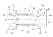
以下,図1〜図11を参照して,この発明による直動案内ユニットの第1実施例を説明する。この直動案内ユニットは,主として,底部31の長手方向両側に側壁部9(第1側壁部)が断面U字状に形成され且つ側壁部9の内側面32に長手方向に沿って軌道溝11(第1軌道溝)が形成された軌道レール1,軌道溝11に対向する軌道溝12(第2軌道溝)を側壁部10の幅方向外側面44に備え且つ軌道レール1の側壁部9間に相対摺動自在なスライダ2,及び軌道溝11と軌道溝12との間に構成される負荷路である軌道路13を転動するボールでなる転動体8から構成されている。軌道レール1は,ステンレス鋼等の金属製の薄肉鋼板の両側を屈曲して対向した側壁部9を備えた断面U字状に形成されている。スライダ2は,軌道溝12が形成された薄肉鋼板で形成されたケーシング3,及びケーシング3に固定され且つ軌道溝12に平行に延びるリターン路14と方向転換路15が形成されたサーキュレータ5から構成されている。転動体8(実施例ではボール)は,軌道路13,方向転換路54及びリターン路14で構成される循環路16を転走する。軌道溝11,12は,例えば,転動体8のボールが摺動抵抗を低減して転動できるように,断面V字状に形成することができる。また,軌道レール1の底部31には,軌道レール1をベッド,フレーム等のベース(図示せず)にねじで螺合して取り付けるための取付け用孔42が形成されている。軌道レール1の側壁部9には,その内側面32に,例えば,長手方向に延びる断面V字状の軌道溝11が形成されている。なお,図示していないが,本出願人に係る特開2003−329036号公報に開示したように,軌道レール1の両端にストッパを設け,軌道レール1からスライダ2が抜け出すのを防止するように構成することもできる。
Hereinafter, a first embodiment of the linear motion guide unit according to the present invention will be described with reference to FIGS. 1 to 11. In this linear motion guide unit, side wall portions 9 (first side wall portions) are mainly formed on both sides of the
この直動案内ユニットにおいて,スライダ2は,ステンレス鋼等の金属製の薄肉鋼板でプレス加工されたケーシング3及びケーシング3を構成するケーシング上部4の下面34に固着された合成樹脂製のサーキュレータ5から構成されている。ケーシング3は,軌道レール1の上方に位置するフランジ部53を備えたケーシング上部4と,軌道レール1の側壁部9にそれぞれ対向してケーシング上部4から中央部に開口29(第1開口)を形成するように幅方向両側にそれぞれ屈曲加工して形成された側壁部10(第2側壁部)とから構成されている。側壁部10には,全長にわたって幅方向外側面44に,例えば,断面V字状の軌道溝12が形成されている。ケーシング上部4には,ワーク,機器,部品等の相手部材(図示せず)を取り付けるため,複数の取付けねじ孔18が形成されている。この直動案内ユニットにおいて,軌道溝11,12は,断面V字状に限らず,断面R字状即ち断面半円形状に形成することもできる。軌道溝11,12を断面半円形状に形成すると,ボールの転動体8と軌道溝11,12との接触面積が大きくなるので,ユニットが負荷を受けるのに有利に働くが,摺動抵抗が大きくなる。また,軌道溝11,12を断面V字状に形成すると,転動体8と軌道溝11,12との接触面積が小さいので,摺動抵抗が小さくなる。この直動案内ユニットでは,軌道レール1とケーシング上部4とを金属製の薄板で形成しているので,軌道溝11,12の形状は摺動抵抗の小さい断面V字状の方が好ましい。
In this linear motion guide unit, the slider 2 is formed from a
この直動案内ユニットは,ケーシング3のケーシング上部4と側壁部10との境界部分には,ケーシング上部4の幅方向に延びる切欠き部19がそれぞれ形成されている。即ち,ケーシング3の側壁部10の長手方向両端に位置するケーシング上部4には,ケーシング上部4の上面35に配設される相手部材のケーシング上部4への取付け時の変形が,側壁部10へ影響するのを防止するため,ケーシング上部4の幅方向に延びる切欠き部19がそれぞれ形成されている。切欠き部19は,特に,ワーク,機器等の相手部材のケーシング上部4への取付け時の変形が側壁部10,特に軌道溝12へ影響して変形するのを防止すると共に,ケーシング上部4からの側壁部10の折り曲げ加工が容易に行えるように形成されている。また,ケーシング3のケーシング上部4には,軌道レール1の上面33を覆って幅方向外側へ突出した四角形状の平板のフランジ部53に形成されており,フランジ部53の平板の四隅には,ワーク,機器,部品等の相手部材を取り付けるため,複数個(実施例では四隅の箇所に1個ずつ)の取付け用ねじ孔18が形成されている。また,ケーシング上部4には,サーキュレータ5をケーシング上部4にリベットを挿入してかしめによって固着するため,複数個のかしめ用孔39が形成されている。サーキュレータ上部6には複数個のかしめ用孔40が形成され,また,サーキュレータ下部7には複数個のかしめ用孔46が形成されている。ケーシング3のケーシング上部4から折り曲げられた側壁部10は,ケーシング上部3の中央部に形成された開口29を形成して下方に延びて形成されており,軌道溝12は,側壁部10の幅方向に外側面44に形成されている。
In this linear motion guide unit, a
スライダ2は,ケーシング3及びケーシング3の下側に配設されたサーキュレータ5から構成されている。サーキュレータ5には,軌道溝11と軌道溝12との間に形成される軌道路13に連通する無負荷路を構成する方向転換路15,及び方向転換路15に連通する無負荷路を構成するリターン路14が形成されている。また,転動体8は,軌道路10,方向転換路15及びリターン路14からなる無限循環路16を転走するように組み込まれている。サーキュレータ5には,転動体8がボールである場合には,ボールの循環をガタが無く滑らかに案内するため,リターン路14と方向転換路15とを断面円形通路に形成する必要がある。そこで,サーキュレータ5に断面円形通路のリターン路14と方向転換路15とを形成するため,サーキュレータ5の加工上から,サーキュレータ5を,通常,上下二分割に形成されたサーキュレータ上部6とサーキュレータ下部7とから合成樹脂材から作製されている。サーキュレータ上部6とサーキュレータ下部7には,半リターン路14Uと14L及び半方向転換路15Uと15Lとの断面半円形通路がそれぞれ形成されており,半リターン路14Uと14L及び半方向転換路15Uと15Lとの断面半円形通路を互いに整合させて合体することによって断面円形通路として,リターン路14と方向転換路15とが形成されることになる。即ち,サーキュレータ5は,サーキュレータ上部6とサーキュレータ下部7とを互いに整合して合体することによって構成され,また,サーキュレータ5にリターン路14と方向転換路15とが形成される。
The slider 2 is composed of a
また,サーキュレータ上部6には,サーキュレータ5をケーシング上部4にリベットを挿入してかしめによって固着するため,複数個のかしめ用孔40が形成されている。ケーシング3のかしめ用孔39とサーキュレータ5のかしめ用孔40とに,リベットを装着してリベットをかしめることによって,ケーシング3にサーキュレータ5を固着するように構成されている。サーキュレータ5を構成するサーキュレータ上部6とサーキュレータ下部7には,ケーシング3の側壁部10が嵌入配設する側面凹部51,52がそれぞれ形成されている。サーキュレータ上部6には,下面26の整合面36に位置決め凸部20と位置決め凸部20から長手方向に隔置して位置決め凹部21されている。サーキュレータ下部7には,上面27の整合面36に位置決め凸部20に嵌入する位置決め凹部23と位置決め凹部21に嵌入する位置決め凸部22が形成されている。サーキュレータ上部6とサーキュレータ下部7とは,位置決め凸部20に位置決め凹部23が嵌入し,且つ位置決め凹部21に位置決め凸部22が嵌入するすることによって,互いに位置決めされて合体することができる。サーキュレータ上部6とサーキュレータ下部7とが整合して合体することによって,断面半円形通路即ち半リターン路14Uと14Lとが整合してリターン路14が形成され,及び断面半円形通路即ち半方向転換路15Uと15Lとが整合して方向転換路15が形成されると共に,サーキュレータ上部6の側面凹部51とサーキュレータ下部7の側面凹部52とが整合して,ケーシング3の側壁部10間にサーキュレータ5が嵌入することができる。
Further, in the
また,この直動案内ユニットは,ケーシング3とサーキュレータ5とを位置決めして固定するため,ケーシング3のケーシング上部4にはノック用孔25が形成され,サーキュレータ5のサーキュレータ上部6にはノック凸部24が形成されている。この直動案内ユニットは,ケーシング3に対してサーキュレータ5を位置決めするため,ケーシング3の側壁部10間に,サーキュレータ5を構成するサーキュレータ上部6の側面凹部51とサーキュレータ下部7の側面凹部52を嵌入すると共に,ケーシング3のノック用孔25にノック凸部24を嵌入させて位置決めしてケーシング3にサーキュレータ5を組み込むことができる。図1に示すように,軌道レール1に形成された取付け用ねじ孔42は,軌道レール1をベース等の構造体に取り付けるためのねじ孔になっている(図8)。ベース側からねじで取り付ける場合にねじ孔を利用する。また,軌道レール1の底部31の上面側からねじで取り付ける場合に,ねじの頭が軌道レール1の底部6の上面から出てしまうので,サーキュレータ5を構成するサーキュレータ下部7の下面38の中央には,長手方向に沿って逃げ溝41(図2)が形成され,サーキュレータ5が取付け用のねじに干渉しないように構成する。
Further, in this linear motion guide unit, since the
スライダ2は,ケーシング3にサーキュレータ5を固定することによって組み立てられるが,例えば,次のようにして,ケーシング3とサーキュレータ5との両者を組み立てることができる。まず,サーキュレータ上部6とサーキュレータ下部7とを整合合体させてサーキュレータ5を形成し,サーキュレータ5のサーキュレータ上部6の側面凹部51とサーキュレータ下部7の側面凹部52とを整合させ,サーキュレータ5の側面凹部51,52をケーシング3の側壁部10間に嵌入すると共に,サーキュレータ上部6の上面37に突出して形成されたノック凸部24をケーシング3のノック用孔25に嵌合して両者を位置決めし,次いで,サーキュレータ5の四隅のかしめ用孔40と,かしめ用孔40に一致した位置にあるケーシング3のかしめ用孔39とに,アルミ製リベットを装着し,リベットをかしめてサーキュレータ5をケーシング3に固着する。更に,転動体8のボールを無限循環路16に組み込み,ボールが脱落しないようにしながらスライダ2を軌道レール1に挿入する。場合によっては,スライダ2を軌道レール1に挿入した後に,無限循環路16に転動体8を組み込むことも可能である。
The slider 2 is assembled by fixing the
次に,図12を参照して,この発明による直動案内ユニットの第2実施例を説明する。この直動案内ユニットは,スライダ2Aを構成するケーシング3のケーシング上部4の平板には,該平板の四隅に形成された取付けねじ孔18が形成されていると共に,更に,ワーク等の相手部材(図示せず)を更に堅固に取り付けるために別の取付けねじ孔47が形成されている。第2実施例は,第1実施例と比較して,別の取付けねじ孔47とスリット28を形成した以外は,実質的に同一構造を有するものである。取付けねじ孔47の周囲には,取付けねじ孔47に螺入する取付けねじの締め付け力が側壁部10の軌道溝12に影響しないように円弧状のスリット28が形成されている。ケーシング上部4の取付けねじ孔47の回りに円弧状のスリット28を形成することによって,ワーク等の相手部材をケーシング上部4にねじ止めする時に,取付けねじ孔47にねじを螺入しても,螺合時のケーシング上部4の変形が,側壁部10に形成した軌道溝12に伝達されずに,軌道溝12の変形が発生しない。
Next, a second embodiment of the linear motion guide unit according to the present invention will be described with reference to FIG. In this linear motion guide unit, mounting screw holes 18 formed at the four corners of the
次に,図13及び図14を参照して,この発明による直動案内ユニットの第3実施例を説明する。この直動案内ユニットにおいて,スライダ2Bを構成するケーシング3のケーシング上部4から折り曲げられた側壁部50(第2側壁部)は,ケーシング上部4の中央部45を残して幅方向に隔置して長手方向に延びる一対の開口30(第2開口)を形成して下方に延びて形成されており,軌道溝12は,側壁部50の幅方向の外側面44に形成されている。第3実施例は,第1実施例がケーシング上部4の中央に開口部29を形成するように側壁部10をプレス加工したのに対して,ケーシング上部4の中央部45を残して中央部45の幅方向両側に開口30を形成するように側壁部50をプレス加工した点で相違している。第3実施例では,ケーシング上部4に形成された取付けねじ孔18,48,特に,ケーシング上部4の中央に形成された取付けねじ孔48は,軌道溝12が形成された側壁部50との間に開口30が存在しているので,ケーシング上部4に相手部材を取り付ける際に,取付け時のケーシング上部4の変形を受け難い構造になっている。従って,第3実施例では,取付けねじ孔48の回りに第2実施例のようなスリットを形成する必要なく,また,側壁部50の両側に位置するケーシング上部4に形成した切欠き部49は,第1実施例や第2実施例に形成した切欠き部19の長さ程は,幅方向に切り込む必要は無い構造に構成されている。
Next, a third embodiment of the linear motion guide unit according to the present invention will be described with reference to FIGS. 13 and 14. In this linear motion guide unit, the side wall portion 50 (second side wall portion) bent from the casing
この発明による曲動転がり案内ユニットは,例えば,各種の組立装置,各種の産業ロボット,精密機械,医療機器等の各種の装置における摺動部に組み込んで利用して好ましいものである。 The bending / rolling guide unit according to the present invention is preferably used by being incorporated into a sliding portion in various devices such as various assembly devices, various industrial robots, precision machines, and medical devices.
1 軌道レール
2 スライダ(第1実施例)
2A スライダ(第2実施例)
2B スライダ(第3実施例)
3 ケーシング
4 ケーシング上部
5 サーキュレータ
6 サーキュレータ上部
7 サーキュレータ下部
8 転動体
9 側壁部(第1側壁部)
10,50 側壁部(第2側壁部)
11 軌道溝(第1軌道溝)
12 軌道溝(第2軌道溝)
13 軌道路
14 リターン路
14U リターン路
14L リターン路
15 方向転換路
15U 方向転換路
15L 方向転換路
16 循環路
18,47,48 取付けねじ孔
19,49 切欠き部(第2側壁部)
20 位置決め凸部(第1位置決め凸部)
21 位置決め凹部(第1位置決め凹部)
22 位置決め凸部(第2位置決め凸部)
23 位置決め凹部(第2位置決め凹部)
24 ノック凸部
25 ノック用孔
26 下面
28 スリット
29 開口(第1開口)
30 開口(第2開口)
31 底部
32 内側面
34 下面
36 整合面
39,40,46 かしめ用孔
43 内側面
44 外側面
45 中央部
51,52 側面凹部
53 フランジ部
1 Track rail 2 Slider (1st embodiment)
2A slider (second embodiment)
2B slider (third embodiment)
3
10,50 side wall (second side wall)
11 Track groove (1st track groove)
12 Orbital groove (second orbital groove)
13
20 Positioning convex part (first positioning convex part)
21 Positioning recess (first positioning recess)
22 Positioning convex part (second positioning convex part)
23 Positioning recess (second positioning recess)
24 Knock
30 openings (second opening)
31
Claims (8)
部の内側面に長手方向に沿って第1軌道溝が形成された薄肉板で形成された軌道レール,
及び前記第1軌道溝に対向する第2軌道溝を有し且つ前記第1軌道溝と前記第2軌道溝と
で形成される軌道路を転動する転動体を介して前記軌道レールに対して相対摺動自在なス
ライダを有する直動案内ユニットにおいて,
前記スライダは,前記第2軌道溝が形成された薄肉板で形成されたケーシング,及び前
記ケーシングに固定され且つ前記第2軌道溝に平行に延びるリターン路と前記リターン路
と前記軌道路とを連通する方向転換路が形成されたサーキュレータから構成され,前記転
動体が前記軌道路,前記方向転換路及び前記リターン路で構成される循環路を転走し,
前記ケーシングは,前記軌道レールの上方で且つ幅方向に延び出したフランジ部を備え
たケーシング上部と,前記軌道レールの前記第1側壁部にそれぞれ対向して前記ケーシン
グ上部から折り曲げられた第2側壁部とから構成され,前記ケーシング上部は,前記軌道
レールの上面を覆って幅方向に突出した四角形状の平板に形成されており,前記平板の四
隅には,相手部材を取り付けるための取付けねじ孔が形成され,
前記サーキュレータは,前記軌道レールの前記第1側壁部間に配設され且つ前記リター
ン路の上側半分と前記方向転換路の上側半分が形成されたサーキュレータ上部と,前記軌
道レールの前記第1側壁部間に配設され且つ前記サーキュレータ上部の下面に接して配設
された前記リターン路の下側半分と前記方向転換路の下側半分が形成されたサーキュレー
タ下部とから構成され,
前記第2側壁部の長手方向両端に位置する前記ケーシング上部には,前記相手部材の前
記ケーシング上部への取付け時の変形が前記第2側壁部に形成された前記第2軌道溝に影
響するのを防止するため,前記ケーシング上部の幅方向に延びる切欠き部がそれぞれ形成
されていることを特徴とする直動案内ユニット。 It was formed of a thin plate having a U-shaped cross section in which first side wall portions were formed on both sides in the longitudinal direction of the bottom portion and a first track groove formed along the longitudinal direction on the inner side surface of the first side wall portion. Track rail,
And with respect to the track rail via a rolling element having a second track groove facing the first track groove and rolling on a track path formed by the first track groove and the second track groove. In a linear motion guide unit having a slider that can slide relative to each other,
The slider communicates a casing formed of a thin-walled plate on which the second track groove is formed, a return path fixed to the casing and extending parallel to the second track groove, the return path, and the track path. It is composed of a circulator in which a direction change path is formed, and the rolling element travels in a circulation path composed of the track path, the direction change path, and the return path.
The casing has an upper casing having a flange portion extending above the track rail and extending in the width direction, and a second side wall bent from the upper casing so as to face the first side wall portion of the track rail. is composed of a part, the casing top, the are formed over a flat plate top surface overlying like square protruding in the width direction of the track rail, the four corners of the flat plate, mounting for attaching the mating member Screw holes are formed
The circulator is arranged between the first side wall portions of the track rail, and the upper half of the return path and the upper half of the direction change path are formed, and the first side wall portion of the track rail. It is composed of a lower half of the return path and a lower half of the circulator formed with the lower half of the direction change path, which are arranged between them and are arranged in contact with the lower surface of the upper part of the circulator.
In the upper part of the casing located at both ends in the longitudinal direction of the second side wall portion, the deformation of the mating member at the time of attachment to the upper part of the casing affects the second track groove formed in the second side wall portion. A linear motion guide unit characterized in that notches extending in the width direction of the upper part of the casing are formed in order to prevent the casing.
が設けられ,前記サーキュレータ下部には長手方向に隔置して第2位置決め凹部と第2位
置決め凸部が形成され,前記第1位置決め凸部が前記第2位置決め凹部に嵌入し,前記第
2位置決め凸部が前記第1位置決め用凹部に嵌入することによって前記サーキュレータ上
部と前記サーキュレータ下部とが互いに位置決めされていることを特徴とする請求項1に
記載の直動案内ユニット。 A first positioning convex portion and a first positioning concave portion are provided on the upper portion of the circulator so as to be separated in the longitudinal direction, and a second positioning concave portion and a second positioning convex portion are formed on the lower portion of the circulator so as to be separated in the longitudinal direction. The first positioning convex portion is fitted into the second positioning concave portion, and the second positioning convex portion is fitted into the first positioning concave portion so that the upper portion of the circulator and the lower portion of the circulator are positioned with each other. The linear motion guide unit according to claim 1, wherein the linear motion guide unit is characterized in that.
記ケーシングにかしめによって固定されていることを特徴とする請求項1又は2に記載の
直動案内ユニット。 The linear motion guide unit according to claim 1 or 2, wherein the upper portion of the circulator and the lower portion of the circulator are formed in a square shape, and four corners are fixed to the casing by caulking.
部に形成された前記第1軌道溝と前記第2側壁部に形成された前記第2軌道溝とはV字形
の軌道溝に形成されていることを特徴とする請求項1〜3のいずれか1項に記載の直動案
内ユニット。 The track rail and the upper part of the casing are formed of a thin steel plate, and the first track groove formed on the first side wall portion and the second track groove formed on the second side wall portion are V-shaped. The linear motion guide unit according to any one of claims 1 to 3, wherein the linear motion guide unit is formed in the track groove of the above.
ック用孔に嵌合して,前記ケーシングと前記サーキュレータ上部とが位置決めして固定さ
れていることを特徴とする請求項1〜4のいずれか1項に記載の直動案内ユニット。 Claim 1 is characterized in that a knock convex portion protruding upward on the upper part of the circulator is fitted into a knock hole formed in the casing, and the casing and the upper part of the circulator are positioned and fixed. The linear motion guide unit according to any one of 1 to 4.
取り付けるための別の取付けねじ孔が形成されており,前記別の取付けねじ孔の周囲には
,前記別の取付けねじ孔に螺入する取付けねじの締め付け力が前記第2側壁部の前記第2
軌道溝に伝達しないように円弧状のスリットが形成されていることを特徴とする請求項1
〜5のいずれか1項に記載の直動案内ユニット。 Another mounting screw hole for mounting the mating member is formed between the mounting screw holes formed at the four corners of the flat plate on the upper part of the casing, and the other mounting screw hole is surrounded by the other mounting screw hole. The tightening force of the mounting screw screwed into the mounting screw hole is the second side wall portion.
Claim 1 characterized in that an arcuate slit is formed so as not to be transmitted to the raceway groove.
The linear motion guide unit according to any one of 5 to 5.
シング上部の中央部に形成された第1開口を形成して下方に延びて形成され,前記第2軌
道溝は,前記第2側壁部の幅方向に外側面に形成されていることを特徴とする請求項1〜
6のいずれか1項に記載の直動案内ユニット。 The second side wall portion of the casing bent from the upper portion of the casing is formed by forming a first opening formed in the central portion of the upper portion of the casing and extending downward, and the second track groove is formed by the second track groove. 2. Claims 1 to be characterized in that the side wall portion is formed on the outer surface in the width direction.
The linear motion guide unit according to any one of 6.
シング上部の中央部を残して幅方向に隔置して長手方向に延びる一対の第2開口を形成し
て下方に延びて形成され,前記第2軌道溝は,前記第2側壁部の幅方向に外側に形成され
ていることを特徴とする請求項1〜6のいずれか1項に記載の直動案内ユニット。 The second side wall portion of the casing, which is bent from the upper part of the casing, forms a pair of second openings extending in the longitudinal direction, separated in the width direction, leaving the central portion of the upper part of the casing, and extends downward. The linear motion guide unit according to any one of claims 1 to 6, wherein the second track groove is formed on the outer side in the width direction of the second side wall portion.
Priority Applications (1)
| Application Number | Priority Date | Filing Date | Title |
|---|---|---|---|
| JP2016021832A JP6876370B2 (en) | 2016-02-08 | 2016-02-08 | Linear guidance unit |
Applications Claiming Priority (1)
| Application Number | Priority Date | Filing Date | Title |
|---|---|---|---|
| JP2016021832A JP6876370B2 (en) | 2016-02-08 | 2016-02-08 | Linear guidance unit |
Publications (3)
| Publication Number | Publication Date |
|---|---|
| JP2017141854A JP2017141854A (en) | 2017-08-17 |
| JP2017141854A5 JP2017141854A5 (en) | 2019-02-21 |
| JP6876370B2 true JP6876370B2 (en) | 2021-05-26 |
Family
ID=59629071
Family Applications (1)
| Application Number | Title | Priority Date | Filing Date |
|---|---|---|---|
| JP2016021832A Active JP6876370B2 (en) | 2016-02-08 | 2016-02-08 | Linear guidance unit |
Country Status (1)
| Country | Link |
|---|---|
| JP (1) | JP6876370B2 (en) |
Families Citing this family (3)
| Publication number | Priority date | Publication date | Assignee | Title |
|---|---|---|---|---|
| WO2019017473A1 (en) | 2017-07-21 | 2019-01-24 | 日本精工株式会社 | Dye-sensitized photoelectric conversion element |
| JP7168471B2 (en) * | 2019-01-30 | 2022-11-09 | 日本トムソン株式会社 | Linear guide unit and its manufacturing method |
| JP7437972B2 (en) | 2020-02-27 | 2024-02-26 | 日本発條株式会社 | Tension balancer for overhead lines |
-
2016
- 2016-02-08 JP JP2016021832A patent/JP6876370B2/en active Active
Also Published As
| Publication number | Publication date |
|---|---|
| JP2017141854A (en) | 2017-08-17 |
Similar Documents
| Publication | Publication Date | Title |
|---|---|---|
| US4630872A (en) | Linear slide bearing | |
| JP4500278B2 (en) | Finite linear motion guide unit equipped with cage slip prevention mechanism | |
| JP6876370B2 (en) | Linear guidance unit | |
| JP3547209B2 (en) | Linear motion rolling guide unit | |
| US9714678B2 (en) | Linear motion guide unit | |
| JP5739205B2 (en) | Crossed roller finite linear motion guide unit | |
| JP4867785B2 (en) | Linear motion guide device | |
| US5088839A (en) | Overrun preventing device of a linear guide apparatus | |
| JP4071975B2 (en) | Linear motion guidance unit | |
| JPH0646050B2 (en) | Linear sliding bearing and linear sliding table | |
| JP4035370B2 (en) | Linear motion guidance unit | |
| WO2018216519A1 (en) | Band for containing plurality of rows of rolling bodies, and motion guide device | |
| JPH07190056A (en) | Track rail mounting structure in direct-acting unit | |
| JP4071974B2 (en) | Linear motion guidance unit | |
| JPS6244171Y2 (en) | ||
| JPH07243443A (en) | Direct acting rolling guide unit | |
| US6939045B1 (en) | Slider of linear guideway | |
| JPS6224646B2 (en) | ||
| US10316889B2 (en) | Finite linear motion guide unit having retainer straying prevention mechanism | |
| JP2015206456A (en) | rolling device | |
| JP7251101B2 (en) | Linear guide | |
| JPS6157137B2 (en) | ||
| JP7027274B2 (en) | Limited linear motion guidance unit | |
| JP2575926B2 (en) | Linear guide device | |
| JPS6224649B2 (en) |
Legal Events
| Date | Code | Title | Description |
|---|---|---|---|
| A521 | Request for written amendment filed |
Free format text: JAPANESE INTERMEDIATE CODE: A523 Effective date: 20190111 |
|
| A621 | Written request for application examination |
Free format text: JAPANESE INTERMEDIATE CODE: A621 Effective date: 20190111 |
|
| A977 | Report on retrieval |
Free format text: JAPANESE INTERMEDIATE CODE: A971007 Effective date: 20191108 |
|
| A131 | Notification of reasons for refusal |
Free format text: JAPANESE INTERMEDIATE CODE: A131 Effective date: 20191210 |
|
| A521 | Request for written amendment filed |
Free format text: JAPANESE INTERMEDIATE CODE: A523 Effective date: 20200122 |
|
| A131 | Notification of reasons for refusal |
Free format text: JAPANESE INTERMEDIATE CODE: A131 Effective date: 20200804 |
|
| A521 | Request for written amendment filed |
Free format text: JAPANESE INTERMEDIATE CODE: A523 Effective date: 20200824 |
|
| RD03 | Notification of appointment of power of attorney |
Free format text: JAPANESE INTERMEDIATE CODE: A7423 Effective date: 20201016 |
|
| RD04 | Notification of resignation of power of attorney |
Free format text: JAPANESE INTERMEDIATE CODE: A7424 Effective date: 20201025 |
|
| A521 | Request for written amendment filed |
Free format text: JAPANESE INTERMEDIATE CODE: A523 Effective date: 20201128 |
|
| TRDD | Decision of grant or rejection written | ||
| A01 | Written decision to grant a patent or to grant a registration (utility model) |
Free format text: JAPANESE INTERMEDIATE CODE: A01 Effective date: 20210413 |
|
| A61 | First payment of annual fees (during grant procedure) |
Free format text: JAPANESE INTERMEDIATE CODE: A61 Effective date: 20210426 |
|
| R150 | Certificate of patent or registration of utility model |
Ref document number: 6876370 Country of ref document: JP Free format text: JAPANESE INTERMEDIATE CODE Ref document number: 6876370 Country of ref document: JP Free format text: JAPANESE INTERMEDIATE CODE: R150 |
|
| R250 | Receipt of annual fees |
Free format text: JAPANESE INTERMEDIATE CODE: R250 |