JP2017169691A - Vehicle seat and its manufacturing method - Google Patents
Vehicle seat and its manufacturing method Download PDFInfo
- Publication number
- JP2017169691A JP2017169691A JP2016057392A JP2016057392A JP2017169691A JP 2017169691 A JP2017169691 A JP 2017169691A JP 2016057392 A JP2016057392 A JP 2016057392A JP 2016057392 A JP2016057392 A JP 2016057392A JP 2017169691 A JP2017169691 A JP 2017169691A
- Authority
- JP
- Japan
- Prior art keywords
- trim cover
- mold pad
- vehicle seat
- film
- manufacturing
- Prior art date
- Legal status (The legal status is an assumption and is not a legal conclusion. Google has not performed a legal analysis and makes no representation as to the accuracy of the status listed.)
- Granted
Links
- 238000004519 manufacturing process Methods 0.000 title claims abstract description 16
- 239000000463 material Substances 0.000 claims abstract description 38
- 239000000853 adhesive Substances 0.000 claims abstract description 30
- 230000001070 adhesive effect Effects 0.000 claims abstract description 30
- 239000010985 leather Substances 0.000 claims abstract description 18
- XLYOFNOQVPJJNP-UHFFFAOYSA-N water Substances O XLYOFNOQVPJJNP-UHFFFAOYSA-N 0.000 claims abstract description 17
- 238000009958 sewing Methods 0.000 claims description 18
- 239000004831 Hot glue Substances 0.000 claims description 13
- 239000004744 fabric Substances 0.000 claims description 9
- 238000000034 method Methods 0.000 claims description 9
- 238000010438 heat treatment Methods 0.000 claims description 5
- -1 The trim cover Substances 0.000 claims description 3
- 239000004698 Polyethylene Substances 0.000 claims description 3
- 239000004952 Polyamide Substances 0.000 claims description 2
- 229920002647 polyamide Polymers 0.000 claims description 2
- 229920006267 polyester film Polymers 0.000 claims description 2
- 229920000573 polyethylene Polymers 0.000 claims description 2
- 229920006264 polyurethane film Polymers 0.000 claims description 2
- 230000000694 effects Effects 0.000 description 3
- 239000000155 melt Substances 0.000 description 2
- 230000002093 peripheral effect Effects 0.000 description 2
- JOYRKODLDBILNP-UHFFFAOYSA-N Ethyl urethane Chemical compound CCOC(N)=O JOYRKODLDBILNP-UHFFFAOYSA-N 0.000 description 1
- 206010037660 Pyrexia Diseases 0.000 description 1
- 238000010586 diagram Methods 0.000 description 1
- 238000002844 melting Methods 0.000 description 1
- 230000008018 melting Effects 0.000 description 1
- 238000012986 modification Methods 0.000 description 1
- 230000004048 modification Effects 0.000 description 1
- 239000013518 molded foam Substances 0.000 description 1
- 239000004814 polyurethane Substances 0.000 description 1
Images


Classifications
-
- A—HUMAN NECESSITIES
- A47—FURNITURE; DOMESTIC ARTICLES OR APPLIANCES; COFFEE MILLS; SPICE MILLS; SUCTION CLEANERS IN GENERAL
- A47C—CHAIRS; SOFAS; BEDS
- A47C31/00—Details or accessories for chairs, beds, or the like, not provided for in other groups of this subclass, e.g. upholstery fasteners, mattress protectors, stretching devices for mattress nets
- A47C31/02—Upholstery attaching means
-
- B—PERFORMING OPERATIONS; TRANSPORTING
- B29—WORKING OF PLASTICS; WORKING OF SUBSTANCES IN A PLASTIC STATE IN GENERAL
- B29C—SHAPING OR JOINING OF PLASTICS; SHAPING OF MATERIAL IN A PLASTIC STATE, NOT OTHERWISE PROVIDED FOR; AFTER-TREATMENT OF THE SHAPED PRODUCTS, e.g. REPAIRING
- B29C65/00—Joining or sealing of preformed parts, e.g. welding of plastics materials; Apparatus therefor
- B29C65/02—Joining or sealing of preformed parts, e.g. welding of plastics materials; Apparatus therefor by heating, with or without pressure
- B29C65/40—Applying molten plastics, e.g. hot melt
-
- B—PERFORMING OPERATIONS; TRANSPORTING
- B68—SADDLERY; UPHOLSTERY
- B68G—METHODS, EQUIPMENT, OR MACHINES FOR USE IN UPHOLSTERING; UPHOLSTERY NOT OTHERWISE PROVIDED FOR
- B68G7/00—Making upholstery
- B68G7/05—Covering or enveloping cores of pads
Abstract
Description
本発明は、車両用シートに係り、特にモールドパッドに表皮材を接着して形成する接着型車両用シートに関する。 The present invention relates to a vehicle seat, and more particularly, to an adhesive vehicle seat formed by bonding a skin material to a mold pad.
車両用シートとして、モールドパッドに表皮材を接着して形成する接着型車両用シートがある。当該技術分野の先行技術として、例えば、実開平5−85833号公報(特許文献1)がある。特許文献1には、下型の型面にセットされたシートカバーに対しモールドパッドがその表面に塗布されたホットメルト接着剤を対面させて重ねられた後、下型に対し上型が型締めされ、上型に配列されたニードルがモールドパッド内に突入された状態のもとで、各ニードルからスチームが噴出され、ホットメルト接着剤が溶融することで接着される接着シートが開示されている。
As a vehicle seat, there is an adhesive vehicle seat formed by adhering a skin material to a mold pad. As prior art in this technical field, for example, there is Japanese Utility Model Publication No. 5-85833 (Patent Document 1). In
しかし、特許文献1では、蒸気を用いてホットメルト接着剤を溶かすため、例えば、熱や水に弱い革の表皮材では、長時間蒸気をあてることが出来ず十分に接着出来なかったり、表面が硬化するという不具合があり、その点について考慮されていなかった。
However, in
本発明はこれらの課題に鑑みなされたものであって、熱や水に弱い表皮材であっても十分な接着ができ、接触面の感触が良い接着型車両用シートを提供することを目的とする。 The present invention has been made in view of these problems, and an object of the present invention is to provide an adhesive-type vehicle seat that can be sufficiently bonded even with a skin material that is weak against heat and water, and has a good contact surface feel. To do.
上記課題を解決するために、本発明は、その一例を挙げるならば、車両用シートであって、モールドパッドと、モールドパッドを覆うトリムカバーを有し、トリムカバーは表皮材として革を用いており、トリムカバーがフィルムを介してモールドパッドと接着されている構成とする。 In order to solve the above-described problems, the present invention is, as an example, a vehicle seat having a mold pad and a trim cover that covers the mold pad, and the trim cover uses leather as a skin material. The trim cover is bonded to the mold pad via a film.
本発明によれば、モールドパッドに表皮材を接着する接着型車両用シートにおいて、熱や水に弱い表皮材であっても十分な接着ができ、接触面の感触が良い車両用シート及びその製造方法を提供することが出来る。 ADVANTAGE OF THE INVENTION According to this invention, in the adhesive-type vehicle seat which adhere | attaches a skin material on a mold pad, even if it is a skin material weak to a heat | fever and water, sufficient adhesion | attachment is possible, and the vehicle seat which has the touch of a contact surface, and its manufacture A method can be provided.
以下、本発明の実施例を図面を用いて説明する。 Embodiments of the present invention will be described below with reference to the drawings.
まず、従来のモールドパッドに表皮材を接着して形成する接着型車両用シートについて説明する。図4は、一般的な車両用シートのシートバックの外観図である。図4において、シートバックは、シート状のカバーが縫製されたトリムカバー1で覆われている。また、2はデザイン性向上のための意匠溝である。
First, an adhesive type vehicle seat formed by adhering a skin material to a conventional mold pad will be described. FIG. 4 is an external view of a seat back of a general vehicle seat. In FIG. 4, the seat back is covered with a
図5は、図4のA―A面での断面図を示している。図5において、3はモールド成形した発泡体製パッドであるモールドパッド、4は意匠溝2を構成するためのモールドパッド3に設けた溝、5は表皮材、6はウレタン等のワディングで、表皮材5とワディング6でトリムカバー1を構成している。また、トリムカバーは複数枚の表皮材とワディングを繋ぎ合わせて構成されており、その縫製部を7に示している。また、溝4には接着剤8が付加されており、その接着剤によりトリムカバー1の縫製部7が溝4に接着される。その接着方法は、まず、押込み板9によりトリムカバー1の縫製部7をモールドパッド3の溝4内に押し込む。ここで、接着剤8はホットメルト接着剤であり、蒸気ノズル10をモールドパッド3内に挿入し、蒸気ノズル10から蒸気11を噴出させ、その蒸気11または加熱によって溝4内の接着剤8を溶融させる。その後、接着剤8が冷却固化することでトリムカバー1が溝4内に接着される。
FIG. 5 is a cross-sectional view taken along plane AA in FIG. In FIG. 5, 3 is a mold pad which is a molded foam pad, 4 is a groove provided in the
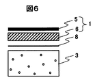
図6に、図5に示すB部における部分断面拡大図を示す。図6は、トリムカバー1を構成する表皮材5及びワディング6と、接着剤8と、モールドパッド3との関係を示した断面図である。図6からもわかるように、従来は蒸気を用いて接着剤8を溶かすため、その蒸気による熱や水が表皮材5にも影響を与え、表皮材5が熱や水に弱い革の場合には、長時間蒸気をあてることが出来ず十分に接着することが出来ないという問題がある。また、熱や水により表面が硬化するという不具合が生じる可能性がある。
FIG. 6 is an enlarged view of a partial cross section in a portion B shown in FIG. FIG. 6 is a cross-sectional view showing the relationship between the
そこで、それを解決する構成について、以下本実施例を説明する。 Therefore, the present embodiment will be described below with regard to a configuration for solving this problem.
図1は本実施例における、図6に対応した、トリムカバー、接着剤及びモールドパッドとの関係を示した断面図である。 FIG. 1 is a cross-sectional view showing the relationship between a trim cover, an adhesive, and a mold pad corresponding to FIG. 6 in this embodiment.
図1において、図6と異なる点は、ワディング6と接着剤8との間にフィルム12を設けた点である。フィルム12は、耐熱性、耐水性、伸縮性を備えたフィルムであり、例えば、PUフィルム(ポリウレタン フィルム)やPEフィルム(ポリエチレン フィルム)やポリエステルフィルムやPAフィルム(ポリアミド フィルム)等である。
1 is different from FIG. 6 in that a
ここで、表皮材5とワディング6は周囲縫いによりトリムカバー1として一体化しており、フィルム12はトリムカバー1のワディング6に溶着または接着されている。また、トリムカバー1とモールドパッド3との間に配置された接着剤8はホットメルト接着剤である。
Here, the
トリムカバー1のモールドパッド3への接着方法は、モールドパッド3のトリムカバー1で覆う反対面からモールドパッド3に蒸気ノズルを挿入し、蒸気ノズルからの加熱または蒸気によってホットメルト接着剤を溶融させてトリムカバー1をフィルム12を介してモールドパッド3に接着させる。
The method of adhering the
ここで、蒸気ノズルからの蒸気による熱や水は、フィルム12により遮られ表皮材5には届かないので、表皮材5が熱や水に弱い革の場合でもその影響を低減できる。よって、接着剤には溶融させるために十分な時間だけ蒸気をあてることが出来るので、十分な接着が可能となる。また、熱や水に弱い革の場合でも蒸気による影響がないので、柔軟性が損なわれることがなく、シート接触面の感触が良い車両用シートを提供することができる。また、蒸気対策としての革の部位指定が必要なく、歩留まりが良くなるという効果や、水分の浸入を防ぐためカビの発生を軽減する効果もある。
Here, since the heat and water by the steam from the steam nozzle are blocked by the
このように、トリムカバー1がフィルム12を介してモールドパッド3に接着される構成とすることで、トリムカバー1の表皮材5を、接着剤を溶融させるための蒸気から保護できるので、十分な接着ができ、表面が硬化するという不具合を解消することができる。
As described above, the
すなわち、本実施例によれば、モールドパッドに表皮材を接着する接着型車両用シートにおいて、熱や水に弱い表皮材であっても十分な接着ができ、接触面の感触が良い車両用シート及びその製造方法を提供することが出来る。 That is, according to the present embodiment, in the adhesive-type vehicle seat for adhering the skin material to the mold pad, even the skin material that is weak against heat and water can be sufficiently adhered and the vehicle seat has a good contact surface feel. And a manufacturing method thereof.
本実施例は、表皮材とワディングの周囲縫いを行う縫製時の作業性向上や接着剤のくいつき向上を図ったトリムカバーの構成について説明する。 In the present embodiment, the configuration of the trim cover for improving the workability at the time of sewing for performing the peripheral sewing of the skin material and the wadding and for improving the adhesion of the adhesive will be described.
図2は本実施例における、トリムカバー、フィルム、接着剤及びモールドパッドとの関係を示した断面図である。 FIG. 2 is a cross-sectional view showing the relationship between the trim cover, film, adhesive, and mold pad in this embodiment.
図2において、図1と異なる点は、ワディング6と接着剤8との間に裏基布13を設け、フィルム12は表皮材5とワディング6の間に設けた点である。
2 is different from FIG. 1 in that a backing base fabric 13 is provided between the
裏基布13をワディング6とともに縫製することで、表皮材5とワディング6の周囲縫い時のミシンの滑りを良くし、縫製の作業性を向上することができる。また、トリムカバーが裏基布13側で裏基布13を介してモールドパッド3と接着することになるので、接着剤のくいつき向上を図ることができる。
By sewing the back base fabric 13 together with the
また、フィルム12は表皮材5とワディング6の間に設けたので、実施例1と同様に、蒸気ノズルからの蒸気による熱や水は、フィルム12により遮られ表皮材5に届かないので、実施例1と同様の、表皮材5が熱や水に弱い革の場合でもその影響を低減できるという効果がある。
In addition, since the
本実施例は、フィルムをワディングに溶着させるのではなく、トリムカバーの剥ぎ合わせ箇所に接着剤と同時に縫い付ける例について説明する。 In this embodiment, an example will be described in which the film is not welded to the wadding, but is sewn together with the adhesive to the trim cover where it is peeled off.
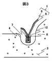
図3は本実施例における、トリムカバー、フィルム、接着剤及びモールドパッドとの関係を示した断面図である。 FIG. 3 is a cross-sectional view showing the relationship between the trim cover, film, adhesive, and mold pad in this embodiment.
図3において、モールドパッド3は溝4を有しており、トリムカバー1の剥ぎ合わせ箇所にフィルム12とシート状のホットメルトの接着剤8とを同時に縫い付けて縫製部7を構成する。そして、その縫製部7を溝4に押し込み、モールドパッド3のトリムカバー1で覆う反対面からモールドパッド3に蒸気ノズルを挿入して、蒸気ノズルからの加熱または蒸気によって溝4のシート状のホットメルト接着剤を溶融させてトリムカバーの縫製部7をフィルム12を介してモールドパッド3の溝4内で接着させる。
In FIG. 3, the
これにより、革の切り口である端面からの蒸気の進入を防ぐことができる。また、トリムカバー1はモールドパッド3の溝4内のみで接着され、他の部分は接着されないため、接着剤の硬化によりトリムカバーの柔軟性が損なわれシートの接触面の感触が悪くなるという不具合も解消できる。
Thereby, the approach of the vapor | steam from the end surface which is a leather cut can be prevented. Further, since the
なお、上記、溝へのトリムカバーの接着方法の説明では、シート状の接着剤をトリムカバーを縫製する際に同時に縫い付ける方法を前提に説明したが、溝内へ接着剤を流し込む方法や、シート状接着剤を溝内に押し込み仮置きとする方法にも適用可能である。 In the above description of the method for adhering the trim cover to the groove, the description has been made on the assumption that the sheet-like adhesive is sewn at the same time when the trim cover is sewn, but the method of pouring the adhesive into the groove, The present invention can also be applied to a method in which a sheet-like adhesive is pushed into a groove and temporarily placed.
以上実施例について説明したが、本発明は上記した実施例に限定されるものではなく、様々な変形例が含まれる。例えば、上記説明では、車両用シートのシートバックについて説明したが、シートバック以外の車両用シートであっても、熱や水に弱い表皮材を接着する際に適用できるのは明らかである。また、上記説明では、表皮材とワディングでトリムカバーを構成しているとして説明したが、これに限定されるものではなく、例えば、モールドパッドを覆う表皮材をトリムカバーとしても良い。 Although the embodiments have been described above, the present invention is not limited to the above-described embodiments, and includes various modifications. For example, in the above description, the seat back of the vehicle seat has been described, but it is obvious that even a vehicle seat other than the seat back can be applied when a skin material that is weak against heat and water is bonded. In the above description, the trim cover is configured by the skin material and the wadding. However, the present invention is not limited to this. For example, the skin material covering the mold pad may be used as the trim cover.
また、上記した実施例は本発明を分かりやすく説明するために詳細に説明したものであり、必ずしも説明した全ての構成を備えるものに限定されるものではない。また、実施例の構成の一部を他の構成に置き換えることも可能である。 The above-described embodiments have been described in detail for easy understanding of the present invention, and are not necessarily limited to those having all the configurations described. In addition, a part of the configuration of the embodiment can be replaced with another configuration.
1…トリムカバー、2…意匠溝、3…モールドパッド、4…溝、5…表皮材、6…ワディング、7…縫製部、8…接着剤、9…押込み板、10…蒸気ノズル、11…蒸気、12…フィルム、13…裏基布
DESCRIPTION OF
Claims (11)
該モールドパッドを覆うトリムカバーを有し、
該トリムカバーは表皮材として革を用いており、
前記トリムカバーがフィルムを介して前記モールドパッドと接着されていることを特徴とする車両用シート。 Mold pad,
A trim cover covering the mold pad;
The trim cover uses leather as the skin material,
The vehicle seat, wherein the trim cover is bonded to the mold pad via a film.
前記フィルムは前記トリムカバーに溶着されていることを特徴とする車両用シート。 The vehicle seat according to claim 1,
The vehicle seat, wherein the film is welded to the trim cover.
前記トリムカバーは革とワディングで構成され、該ワディング側が前記モールドパッドと接着されていることを特徴とする車両用シート。 The vehicle seat according to claim 1 or 2,
The vehicle seat according to claim 1, wherein the trim cover is made of leather and wadding, and the wadding side is bonded to the mold pad.
該モールドパッドを覆うトリムカバーを有し、
該トリムカバーは革とフィルムとワディングと裏基布で構成され、
前記トリムカバーが前記裏基布側で前記モールドパッドと接着されていることを特徴とする車両用シート。 Mold pad,
A trim cover covering the mold pad;
The trim cover is composed of leather, film, wadding and back base fabric,
The vehicle seat, wherein the trim cover is bonded to the mold pad on the back base fabric side.
該モールドパッドを覆うトリムカバーを有し、
前記モールドパッドは溝を有しており、
前記トリムカバーは表皮材として革を用いており、
前記トリムカバーとフィルムとシート状の接着剤とを該トリムカバーの縫製時に同時に縫い付け縫製部を構成し、
前記縫製部が前記溝内に配置され、前記トリムカバーが前記フィルムを介して前記モールドパッドの溝内で接着されていることを特徴とする車両用シート。 Mold pad,
A trim cover covering the mold pad;
The mold pad has a groove,
The trim cover uses leather as the skin material,
The trim cover, the film, and the sheet-like adhesive are sewn at the same time when the trim cover is sewn to form a sewing portion,
The vehicle seat, wherein the sewing portion is disposed in the groove, and the trim cover is bonded in the groove of the mold pad via the film.
該トリムカバーは表皮材として革を用いており、
前記トリムカバーにフィルムが溶着されており、
前記トリムカバーと前記モールドパッドの間にホットメルト接着剤を配置し、
前記モールドパッドの前記トリムカバーで覆う反対面から該モールドパッドに蒸気ノズルを挿入し、
前記蒸気ノズルからの加熱または蒸気によって前記ホットメルト接着剤を溶融させて前記トリムカバーを前記フィルムを介して前記モールドパッドと接着させることを特徴とする車両用シートの製造方法。 A method of manufacturing a vehicle seat having a mold pad and a trim cover that covers the mold pad,
The trim cover uses leather as the skin material,
A film is welded to the trim cover,
Place hot melt adhesive between the trim cover and the mold pad,
Inserting a steam nozzle into the mold pad from the opposite surface covered with the trim cover of the mold pad,
The vehicle seat manufacturing method, wherein the hot melt adhesive is melted by heating from the steam nozzle or steam to bond the trim cover to the mold pad through the film.
前記トリムカバーは革とワディングで構成され、該ワディング側を前記モールドパッドと接着することを特徴とする製造方法。 It is a manufacturing method of the vehicular seat according to claim 6,
The manufacturing method, wherein the trim cover is made of leather and wadding, and the wadding side is bonded to the mold pad.
該トリムカバーは革とフィルムとワディングと裏基布で構成され、
前記トリムカバーと前記モールドパッドの間にホットメルト接着剤を配置し、
前記モールドパッドの前記トリムカバーで覆う反対面から該モールドパッドに蒸気ノズルを挿入し、
前記蒸気ノズルからの加熱または蒸気によって前記ホットメルト接着剤を溶融させて前記トリムカバーを前記裏基布側で前記モールドパッドと接着させることを特徴とする車両用シートの製造方法。 A method of manufacturing a vehicle seat having a mold pad and a trim cover that covers the mold pad,
The trim cover is composed of leather, film, wadding and back base fabric,
Place hot melt adhesive between the trim cover and the mold pad,
Inserting a steam nozzle into the mold pad from the opposite surface covered with the trim cover of the mold pad,
The vehicle seat manufacturing method, wherein the hot melt adhesive is melted by heating from the steam nozzle or steam to bond the trim cover to the mold pad on the back base fabric side.
前記モールドパッドは溝を有しており、
該トリムカバーは表皮材として革を用いており、
前記トリムカバーとフィルムとシート状のホットメルト接着剤とを該トリムカバーの縫製時に同時に縫い付け縫製部を構成し、
前記縫製部を前記溝内に配置し、
前記モールドパッドの前記トリムカバーで覆う反対面から該モールドパッドに蒸気ノズルを挿入し、
前記蒸気ノズルからの加熱または蒸気によって前記溝内のシート状のホットメルト接着剤を溶融させて前記トリムカバーを前記フィルムを介して前記モールドパッドの溝内で接着させることを特徴とする車両用シートの製造方法。 A method of manufacturing a vehicle seat having a mold pad and a trim cover that covers the mold pad,
The mold pad has a groove,
The trim cover uses leather as the skin material,
The trim cover, film, and sheet-like hot melt adhesive are sewn at the same time when the trim cover is sewn to constitute a sewing part,
Arranging the sewing portion in the groove;
Inserting a steam nozzle into the mold pad from the opposite surface covered with the trim cover of the mold pad,
A vehicle seat characterized in that the sheet-like hot melt adhesive in the groove is melted by heating from the steam nozzle or steam to bond the trim cover in the groove of the mold pad through the film. Manufacturing method.
前記フィルムは、耐熱性、耐水性、伸縮性を備えたフィルムであることを特徴とする車両用シートまたは車両用シートの製造方法。 A method for manufacturing a vehicle seat or a vehicle seat according to any one of claims 1 to 9,
The said film is a film provided with heat resistance, water resistance, and elasticity, The manufacturing method of the vehicle seat or the vehicle seat characterized by the above-mentioned.
前記フィルムは、ポリウレタン フィルム、ポリエチレン フィルム、ポリエステルフィルム、ポリアミド フィルムのいずれかであることを特徴とする車両用シートまたは車両用シートの製造方法。 A method for manufacturing a vehicle seat or a vehicle seat according to claim 10,
The said film is a polyurethane film, a polyethylene film, a polyester film, and a polyamide film, The manufacturing method of the vehicle seat or the vehicle seat characterized by the above-mentioned.
Priority Applications (2)
| Application Number | Priority Date | Filing Date | Title |
|---|---|---|---|
| JP2016057392A JP6632440B2 (en) | 2016-03-22 | 2016-03-22 | Vehicle seat and manufacturing method thereof |
| PCT/JP2017/006913 WO2017163750A1 (en) | 2016-03-22 | 2017-02-23 | Vehicle seat and method for manufacturing same |
Applications Claiming Priority (1)
| Application Number | Priority Date | Filing Date | Title |
|---|---|---|---|
| JP2016057392A JP6632440B2 (en) | 2016-03-22 | 2016-03-22 | Vehicle seat and manufacturing method thereof |
Publications (2)
| Publication Number | Publication Date |
|---|---|
| JP2017169691A true JP2017169691A (en) | 2017-09-28 |
| JP6632440B2 JP6632440B2 (en) | 2020-01-22 |
Family
ID=59901260
Family Applications (1)
| Application Number | Title | Priority Date | Filing Date |
|---|---|---|---|
| JP2016057392A Active JP6632440B2 (en) | 2016-03-22 | 2016-03-22 | Vehicle seat and manufacturing method thereof |
Country Status (2)
| Country | Link |
|---|---|
| JP (1) | JP6632440B2 (en) |
| WO (1) | WO2017163750A1 (en) |
Cited By (1)
| Publication number | Priority date | Publication date | Assignee | Title |
|---|---|---|---|---|
| JP2019214296A (en) * | 2018-06-13 | 2019-12-19 | 株式会社タチエス | Seat |
Citations (12)
| Publication number | Priority date | Publication date | Assignee | Title |
|---|---|---|---|---|
| JPS6211489A (en) * | 1985-07-10 | 1987-01-20 | 日産自動車株式会社 | Production of button |
| JPH0233698U (en) * | 1988-08-26 | 1990-03-02 | ||
| JPH02200296A (en) * | 1989-01-31 | 1990-08-08 | Tachi S Co Ltd | Assembling method for seat |
| JPH04253892A (en) * | 1990-12-31 | 1992-09-09 | Tokyo Seat Kk | Fixing method for hanging member of seat skin |
| JPH0585833U (en) * | 1992-04-22 | 1993-11-19 | アラコ株式会社 | Adhesive structure of adhesive sheet |
| JPH06170068A (en) * | 1992-12-01 | 1994-06-21 | Araco Corp | Mold structure for needle type skin adhesive sheet |
| JPH06182067A (en) * | 1992-12-21 | 1994-07-05 | Inoac Corp | Cushion material and manufacture thereof |
| JP2003088689A (en) * | 2001-09-19 | 2003-03-25 | Nhk Spring Co Ltd | Production method of seat |
| US20090096261A1 (en) * | 2007-10-12 | 2009-04-16 | Tim Abraham | Apparatus for Preventing Transfer of Odors From a Vehicle to a Hunter |
| JP2013031689A (en) * | 2006-05-11 | 2013-02-14 | Kci Licensing Inc | Multi-layered support system |
| JP2016120844A (en) * | 2014-12-25 | 2016-07-07 | 株式会社タチエス | Vehicle seat and manufacturing method of the same |
| JP2017056773A (en) * | 2015-09-15 | 2017-03-23 | 株式会社タチエス | Vehicle seat and method for manufacturing the same |
Family Cites Families (2)
| Publication number | Priority date | Publication date | Assignee | Title |
|---|---|---|---|---|
| JPH085074B2 (en) * | 1986-08-08 | 1996-01-24 | 株式会社タチエス | Seat body manufacturing method |
| JP3242984B2 (en) * | 1992-04-27 | 2001-12-25 | 株式会社ブリヂストン | Manufacturing method of laminate |
-
2016
- 2016-03-22 JP JP2016057392A patent/JP6632440B2/en active Active
-
2017
- 2017-02-23 WO PCT/JP2017/006913 patent/WO2017163750A1/en active Application Filing
Patent Citations (12)
| Publication number | Priority date | Publication date | Assignee | Title |
|---|---|---|---|---|
| JPS6211489A (en) * | 1985-07-10 | 1987-01-20 | 日産自動車株式会社 | Production of button |
| JPH0233698U (en) * | 1988-08-26 | 1990-03-02 | ||
| JPH02200296A (en) * | 1989-01-31 | 1990-08-08 | Tachi S Co Ltd | Assembling method for seat |
| JPH04253892A (en) * | 1990-12-31 | 1992-09-09 | Tokyo Seat Kk | Fixing method for hanging member of seat skin |
| JPH0585833U (en) * | 1992-04-22 | 1993-11-19 | アラコ株式会社 | Adhesive structure of adhesive sheet |
| JPH06170068A (en) * | 1992-12-01 | 1994-06-21 | Araco Corp | Mold structure for needle type skin adhesive sheet |
| JPH06182067A (en) * | 1992-12-21 | 1994-07-05 | Inoac Corp | Cushion material and manufacture thereof |
| JP2003088689A (en) * | 2001-09-19 | 2003-03-25 | Nhk Spring Co Ltd | Production method of seat |
| JP2013031689A (en) * | 2006-05-11 | 2013-02-14 | Kci Licensing Inc | Multi-layered support system |
| US20090096261A1 (en) * | 2007-10-12 | 2009-04-16 | Tim Abraham | Apparatus for Preventing Transfer of Odors From a Vehicle to a Hunter |
| JP2016120844A (en) * | 2014-12-25 | 2016-07-07 | 株式会社タチエス | Vehicle seat and manufacturing method of the same |
| JP2017056773A (en) * | 2015-09-15 | 2017-03-23 | 株式会社タチエス | Vehicle seat and method for manufacturing the same |
Cited By (2)
| Publication number | Priority date | Publication date | Assignee | Title |
|---|---|---|---|---|
| JP2019214296A (en) * | 2018-06-13 | 2019-12-19 | 株式会社タチエス | Seat |
| JP7013328B2 (en) | 2018-06-13 | 2022-01-31 | 株式会社タチエス | Seat |
Also Published As
| Publication number | Publication date |
|---|---|
| WO2017163750A1 (en) | 2017-09-28 |
| JP6632440B2 (en) | 2020-01-22 |
Similar Documents
| Publication | Publication Date | Title |
|---|---|---|
| JP6552826B2 (en) | Vehicle seat and method of manufacturing the same | |
| JP6339694B2 (en) | Method for manufacturing an element having a cover and such an element | |
| JP2017518910A5 (en) | ||
| JP2008001001A (en) | Method for manufacturing vehicle interior material | |
| JP2016129645A5 (en) | ||
| WO2007032071A1 (en) | Slip preventive for waistcloth and waistcloth with this slip preventive attached thereto | |
| WO2017163750A1 (en) | Vehicle seat and method for manufacturing same | |
| JP2016120843A (en) | Vehicle seat | |
| US20180148313A1 (en) | Base fabric material having pad member with core and manufacturing method thereof | |
| JP7013328B2 (en) | Seat | |
| KR101331588B1 (en) | A fabric | |
| JP2003088689A (en) | Production method of seat | |
| CN109153344B (en) | Edge strip, seat cover and seat comprising seat cover | |
| JP3136098U (en) | shorts | |
| JP7060883B2 (en) | How to apply the skin material | |
| JP2000342381A (en) | Seat with heater | |
| JP2004119264A (en) | Plane heating element | |
| JP6093698B2 (en) | Method for manufacturing slip prevention tool and slip prevention tool | |
| JP2008018655A (en) | Skin material for vehicle seat | |
| KR20160072856A (en) | Method and structure for assembling rear seat cover of vehicle | |
| KR20160055364A (en) | Steering wheel heater for vehicle | |
| JP5627939B2 (en) | Manufacturing method of adhesive sheet | |
| JPH06134071A (en) | Method for manufacturing supporter or the like provided with protective member | |
| JP3118382U (en) | Shock absorbing pad | |
| JPH0426268Y2 (en) |
Legal Events
| Date | Code | Title | Description |
|---|---|---|---|
| A621 | Written request for application examination |
Free format text: JAPANESE INTERMEDIATE CODE: A621 Effective date: 20180801 |
|
| A131 | Notification of reasons for refusal |
Free format text: JAPANESE INTERMEDIATE CODE: A131 Effective date: 20190702 |
|
| A521 | Request for written amendment filed |
Free format text: JAPANESE INTERMEDIATE CODE: A523 Effective date: 20190805 |
|
| TRDD | Decision of grant or rejection written | ||
| A01 | Written decision to grant a patent or to grant a registration (utility model) |
Free format text: JAPANESE INTERMEDIATE CODE: A01 Effective date: 20191119 |
|
| A61 | First payment of annual fees (during grant procedure) |
Free format text: JAPANESE INTERMEDIATE CODE: A61 Effective date: 20191210 |
|
| R150 | Certificate of patent or registration of utility model |
Ref document number: 6632440 Country of ref document: JP Free format text: JAPANESE INTERMEDIATE CODE: R150 |
|
| R250 | Receipt of annual fees |
Free format text: JAPANESE INTERMEDIATE CODE: R250 |
|
| S531 | Written request for registration of change of domicile |
Free format text: JAPANESE INTERMEDIATE CODE: R313531 |
|
| R350 | Written notification of registration of transfer |
Free format text: JAPANESE INTERMEDIATE CODE: R350 |
|
| R250 | Receipt of annual fees |
Free format text: JAPANESE INTERMEDIATE CODE: R250 |