JP2017169310A - Stator - Google Patents
Stator Download PDFInfo
- Publication number
- JP2017169310A JP2017169310A JP2016050966A JP2016050966A JP2017169310A JP 2017169310 A JP2017169310 A JP 2017169310A JP 2016050966 A JP2016050966 A JP 2016050966A JP 2016050966 A JP2016050966 A JP 2016050966A JP 2017169310 A JP2017169310 A JP 2017169310A
- Authority
- JP
- Japan
- Prior art keywords
- teeth
- stator
- axial direction
- wound
- wound around
- Prior art date
- Legal status (The legal status is an assumption and is not a legal conclusion. Google has not performed a legal analysis and makes no representation as to the accuracy of the status listed.)
- Granted
Links
Images

Classifications
-
- Y—GENERAL TAGGING OF NEW TECHNOLOGICAL DEVELOPMENTS; GENERAL TAGGING OF CROSS-SECTIONAL TECHNOLOGIES SPANNING OVER SEVERAL SECTIONS OF THE IPC; TECHNICAL SUBJECTS COVERED BY FORMER USPC CROSS-REFERENCE ART COLLECTIONS [XRACs] AND DIGESTS
- Y02—TECHNOLOGIES OR APPLICATIONS FOR MITIGATION OR ADAPTATION AGAINST CLIMATE CHANGE
- Y02T—CLIMATE CHANGE MITIGATION TECHNOLOGIES RELATED TO TRANSPORTATION
- Y02T10/00—Road transport of goods or passengers
- Y02T10/60—Other road transportation technologies with climate change mitigation effect
- Y02T10/64—Electric machine technologies in electromobility
Abstract
Description
本発明は、電動モータに用いられるステータに関する。 The present invention relates to a stator used for an electric motor.
近年、エンジンと電動モータとを併用することで車両の燃料消費率(燃費)を効果的に向上させることができるハイブリッド自動車(HEV)が広く実用化されている。また、電動モータのみを動力源とし、排気ガスを排出しない電気自動車(EV)も実用化されている。 In recent years, hybrid vehicles (HEV) that can effectively improve the fuel consumption rate (fuel consumption) of a vehicle by using an engine and an electric motor in combination have been widely put into practical use. In addition, an electric vehicle (EV) that uses only an electric motor as a power source and does not discharge exhaust gas has been put into practical use.
このようなハイブリッド自動車や電気自動車では、例えば、小型で高効率な永久磁石式同期モータ(PM同期モータ)などが好適に用いられている。永久磁石式同期モータは、ロータ(回転子)に永久磁石(Permanent Magnet)を内蔵し、ステータ(固定子)に電機子巻線(ステータ巻線)を設けた回転界磁形の電動機である。 In such hybrid vehicles and electric vehicles, for example, a small and highly efficient permanent magnet type synchronous motor (PM synchronous motor) is suitably used. The permanent magnet type synchronous motor is a rotating field type electric motor in which a permanent magnet (Permanent Magnet) is built in a rotor (rotor) and an armature winding (stator winding) is provided in a stator (stator).
ここで、特許文献1には、ステータ巻線の占積率(コイル断面積に占める導体断面積の割合)を向上させる技術(ステータ巻線)が開示されている。より詳細には、このステータ巻線は、ステータの円周方向に所定間隔毎に配置された複数のティース毎に平角線が複数列かつ複数層に集中的に巻回されたステータ巻線であって、ステータの径方向に沿った複数列の各列毎に、平角線が複数層を成すように渦巻状に巻回された渦状コイル部を備え、複数の渦状コイル部が複数列を成すようにステータの径方向に沿って配列されている。
Here,
この構成のステータ巻線では、例えば列方向で隣り合う渦状コイル部同士を接続する接続部のみにおいて平角線を隣り合う列に列替わりさせることにより、例えば平角線が複数列かつ複数層に巻回されたステータ巻線の各層において列替わり部が形成されてしまうことを防止している。これにより、平角線の列替わりの回数に応じて増大する平角線の変形の累積量や単位周回あたりの巻線長が過剰に増大してしまうことを防止して、ステータ巻線の占積率を向上させている。 In the stator winding of this configuration, for example, by switching the flat wire to the adjacent row only in the connecting portion that connects the spiral coil portions adjacent in the row direction, for example, the flat wire is wound in multiple rows and multiple layers. Thus, it is possible to prevent replacement parts from being formed in each layer of the stator winding. This prevents the cumulative amount of deformation of the rectangular wire that increases with the number of replacements of the rectangular wire and the winding length per unit turn from excessively increasing, and the stator winding space factor. Has improved.
しかしながら、上述したステータ巻線の構成では、隣り合うティースそれぞれに巻回されたステータ巻線間の距離(絶縁距離/相間距離)を、ティースの軸線方向に沿って均一(又は略均一)にすることが困難である。ここで、ステータ巻線の絶縁特性は、通常、最も短い距離に基づいて決定されるため、上記距離が離れている箇所ではオーバースペックとなるおそれがある。すなわち、余分な絶縁距離が生じるおそれがある。 However, in the configuration of the stator winding described above, the distance between the stator windings wound around each adjacent tooth (insulation distance / interphase distance) is made uniform (or substantially uniform) along the axial direction of the teeth. Is difficult. Here, since the insulation characteristic of the stator winding is usually determined based on the shortest distance, there is a possibility that the specification is over-specificated at a location where the distance is long. That is, an extra insulation distance may occur.
本発明は、上記問題点を解消する為になされたものであり、隣り合うティースそれぞれに巻回されたステータ巻線間の距離をより均一にすることが可能なステータを提供することを目的とする。 The present invention has been made to solve the above problems, and an object of the present invention is to provide a stator capable of making the distance between the stator windings wound around adjacent teeth more uniform. To do.
本発明に係るステータは、周方向に沿って所定の間隔を空けて配置され径方向内方に延伸する複数のティースを有する、円環状のステータコアと、ティースに巻回されたステータ巻線とを備え、ティースが、先端部の断面積が基端部の断面積よりも小さくなるようにテーパ状に形成されており、ステータ巻線が、ティースの軸線と直行する平面に対して所定の傾斜角を持ちつつ、ティースの軸線方向に沿って、螺旋状に巻回されていることを特徴とする。 A stator according to the present invention includes an annular stator core having a plurality of teeth arranged at predetermined intervals along the circumferential direction and extending radially inward, and a stator winding wound around the teeth. The teeth are tapered so that the cross-sectional area of the tip end portion is smaller than the cross-sectional area of the base end portion, and the stator winding has a predetermined inclination angle with respect to a plane perpendicular to the tooth axis. It is characterized by being wound spirally along the axial direction of the teeth.
本発明に係るステータによれば、先端部(一方の端部)の断面積が基端部(他方の端部)の断面積よりも小さくなるように、ティースがテーパ状に形成されており、かつ、ステータ巻線が、ティースの軸線と直行する平面に対して所定の傾斜角を持ちつつ、ティースの軸線方向に沿って、螺旋状に巻回されている。そのため、隣り合うティースに巻回されたステータ巻線それぞれの凸部と凸部とが、ティースの軸線方向に沿って、互い違いに配置されるように(すなわち互いの位相がずれるように)巻回することができる。その結果、隣り合うティースそれぞれに巻回されたステータ巻線間の距離を、拡げることなくより均一にすることが可能となる。また、その結果、最短絶縁距離を拡大すること、又はステータ巻線の占積率を向上させることも可能となる。 According to the stator according to the present invention, the teeth are formed in a tapered shape so that the cross-sectional area of the distal end portion (one end portion) is smaller than the cross-sectional area of the base end portion (the other end portion), The stator winding is wound spirally along the axial direction of the teeth while having a predetermined inclination angle with respect to a plane perpendicular to the axial line of the teeth. Therefore, winding is performed so that the convex portions and the convex portions of the stator windings wound around the adjacent teeth are alternately arranged along the axial direction of the teeth (that is, the phases thereof are shifted). can do. As a result, the distance between the stator windings wound around the adjacent teeth can be made more uniform without increasing. As a result, the shortest insulation distance can be increased, or the space factor of the stator winding can be improved.
また、本発明に係るステータでは、ティースの軸線方向に沿って、ティースの外側面に階段状の段差が形成されており、該軸線方向に沿った断面で見た場合に、両側面に形成された階段状の段差の位置が軸線方向に対してオフセットされていることが好ましい。 Further, in the stator according to the present invention, a stepped step is formed on the outer surface of the tooth along the axial direction of the tooth, and is formed on both side surfaces when viewed in a cross section along the axial direction. It is preferable that the position of the stepped step is offset with respect to the axial direction.
この場合、ティースの軸線方向に沿って、外側面に階段状の段差が形成されており、該軸線方向に沿った断面で見た場合に、両側面に形成された階段状の段差の位置が軸線方向に対してオフセットされている。すなわち、ティースの外側面に階段状の段差が螺旋状に形成されている。そのため、該段差に合わせてステータ巻線を巻回することにより、隣り合うティースに巻回されたステータ巻線それぞれの凸部と凸部が、ティースの軸線方向に沿って互い違いに配置されるように(互いに位相がずれるように)巻回することが可能となる。 In this case, a stepped step is formed on the outer surface along the axial direction of the teeth, and when viewed in a cross section along the axial direction, the position of the stepped step formed on both side surfaces is It is offset with respect to the axial direction. That is, a stepped step is spirally formed on the outer surface of the tooth. Therefore, by winding the stator winding in accordance with the step, the convex portions and the convex portions of the stator windings wound around the adjacent teeth are arranged alternately along the axial direction of the teeth. (So that the phases are shifted from each other).
特に、本発明に係るステータでは、上記ステータ巻線が、平角線からなり、隣り合うティースそれぞれの軸線を通る断面で見た場合に、隣り合うティースそれぞれに巻回された各平角線の角部と角部とが、ティースの軸線方向に沿って互い違いに配置されていることが好ましい。 In particular, in the stator according to the present invention, when the stator winding is formed of a flat wire and viewed in a cross section passing through the axis of each adjacent tooth, the corner portion of each flat wire wound around each adjacent tooth. And the corners are preferably arranged alternately along the axial direction of the teeth.
この場合、ステータ巻線が、平角線からなり、隣り合うティースそれぞれの軸線を通る断面で見た場合(すなわちステータコアの中心軸方向から見た場合)に、隣り合うティースそれぞれに巻回された各平角線(ステータ巻線)の角部と角部とが、ティースの軸線方向に沿って互い違いに(すなわち互いに位相がずれるように)配置されている。そのため、隣り合うティースそれぞれに巻回されたステータ巻線間(平角線間)の距離を、拡げることなくより均一にすることが可能となる。 In this case, when the stator winding is a flat wire and viewed in a cross section passing through the axis of each adjacent tooth (that is, viewed from the direction of the central axis of the stator core), each wound around each adjacent tooth Corners and corners of the flat wire (stator winding) are arranged alternately (that is, out of phase with each other) along the axial direction of the teeth. Therefore, it becomes possible to make the distance between the stator windings (between the rectangular wires) wound around the adjacent teeth more uniform without increasing the distance.
特に、本発明に係るステータでは、テーパ状に形成されたティースのテーパ角が、隣り合うティースそれぞれに巻回された平角線間の距離が略一定となるように設定されていることが好ましい。 In particular, in the stator according to the present invention, it is preferable that the taper angle of the teeth formed in a tapered shape is set so that the distance between the rectangular wires wound around the adjacent teeth is substantially constant.
この場合、ティースのテーパ角が、隣り合うティースそれぞれに巻回された平角線間(ステータ巻線間)の距離が略一定となるように設定されているため、ステータ巻線の占積率をより向上させることが可能となる。 In this case, the taper angle of the teeth is set so that the distance between the rectangular wires wound between the adjacent teeth (between the stator windings) is substantially constant. This can be further improved.
また、本発明に係るステータでは、上記所定の傾斜角が、平角線の厚みに応じて、螺旋状に巻回される平角線を隙間なく巻回することができる角度に設定されていることが好ましい。 Further, in the stator according to the present invention, the predetermined inclination angle may be set to an angle at which the rectangular wire wound spirally can be wound without a gap depending on the thickness of the rectangular wire. preferable.
この場合、上記所定の傾斜角が、平角線の厚みに応じて、螺旋状に巻回される平角線を隙間なく巻回することができる角度に設定されているため、ステータ巻線の占積率をより向上させることが可能となる。 In this case, since the predetermined inclination angle is set to an angle at which the rectangular wire wound spirally can be wound without gaps in accordance with the thickness of the rectangular wire, The rate can be further improved.
なお、本発明に係るステータでは、ティースに巻回されるn層目(ただしnは自然数)の平角線が、ティースの基端側から先端側に巻回され、n+1層目の平角線が、ティースの先端側から基端側へ巻回されることが好ましい。 In the stator according to the present invention, the n-th layer (where n is a natural number) rectangular wire wound around the teeth is wound from the proximal end side to the distal end side of the teeth, and the n + 1-th layer rectangular wire is It is preferable that the teeth are wound from the distal end side to the proximal end side.
このようにすれば、例えば、層替わりを行う際に、斜め掛けなどを行うことなく、平角線を整列して連続的に巻回することができる。 In this way, for example, when the layers are changed, the rectangular wires can be aligned and wound continuously without performing oblique hanging or the like.
本発明によれば、隣り合うティースそれぞれに巻回されたステータ巻線間の距離をより均一にすることが可能となる。 According to the present invention, it is possible to make the distance between the stator windings wound around the adjacent teeth more uniform.
以下、図面を参照して本発明の好適な実施形態について詳細に説明する。なお、特に区別する必要がある場合を除いて、図中、同一又は相当部分には同一符号を用いることとする。また、各図において、同一要素には同一符号を付して重複する説明を省略する。 DESCRIPTION OF EMBODIMENTS Hereinafter, preferred embodiments of the present invention will be described in detail with reference to the drawings. Note that the same reference numerals are used for the same or corresponding parts in the drawings, unless otherwise required. Moreover, in each figure, the same code | symbol is attached | subjected to the same element and the overlapping description is abbreviate | omitted.
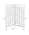
まず、図1、図2を併せて用いて、実施形態に係るステータ1の構成について説明する。図1は、実施形態に係るステータの構造(要部)を示す断面図である。また、図2は、図1のスロット部(図1の長方形部)を拡大して示した図である。
First, the configuration of the
ステータ1は、断面形状が略矩形の平角線を用いた集中巻きのステータであって、例えば、永久磁石(Permanent Magnet)を内蔵し該ステータ1の内側に配設されるロータ(回転子)(図示省略)を有する永久磁石式同期モータ(PM同期モータ)などにおいて好適に用いられる。
The
ステータ1は、主として、複数のティース202を有する円環状(円筒状)のステータコア10と、各ティース202それぞれに巻回されたステータ巻線30とを有して構成されている。
The
ステータコア10は、例えば、ステータセグメント(分割コア)20がステータ1の周方向に複数(例えば12個等)配列されることにより、円環状(円筒状)に構成されている。各ステータセグメント20は、ステータコア10の周方向に延出する円弧状のヨーク201と、ステータコア10の径方向内方に向けて突出する複数のティース202とを含んで構成されている。また、各ステータセグメント20は、例えば、珪素鋼板等の方向性を有する電磁鋼板が積層されて構成される。
The
上述したように構成されることにより、ステータコア10には、周方向に沿って、所定の間隔毎に、径方向内方に延伸する複数のティース202が配置される。なお、ティース202はステータコア10の全内周に亘って形成されているが、図1では、その中の2つのステータセグメント20(ティース202)のみを示した。
By being configured as described above, the
ティース202は、ステータコア10の半径方向(ティース202の軸線)に直交する平面によって切断した場合に、略矩形(又は円形)の断面形状を示すように形成されている。また、ティース202は、先端部(一方の端部)の断面積(ティース202の軸線と直交する断面の断面積)(又は径)が基端部(他方の端部)の断面積(又は径)よりも小さくなるようにテーパ状に形成されている。ここで、テーパ状に形成されたティース202のテーパ角(図1中のθ1)は、隣り合うティース202それぞれに巻回されたステータ巻線30間(平角線間)の距離(詳細は後述する)が略一定となるように設定されることが好ましい。
The
また、ティース202には、軸線方向に沿って、外側面に階段状の段差(ガイド凸部)が形成されており、軸線方向に沿った断面で見た場合に、両側面に形成された階段状の段差の位置(すなわち巻線位置)が、軸線方向(すなわちステータコア10の径方向)に対してオフセットされている(位相差が設けられている)。すなわち、ティース202の外側面には階段状の段差が螺旋状に形成されている。なお、上記段差(ガイド凸部)は、例えば、平角線の寸法や、巻線形状などに応じて設定することが好ましい。
Further, the
ティース202の側面には、銅等の高導電性線材をエナメル等の絶縁材料で被覆した巻線からなるステータ巻線(固定子巻線)30が巻装されている。本実施形態においては、短手方向の断面形状が略矩形に形成されたいわゆる平角線が各ティース202に集中巻きで巻回されてステータ巻線30を形成している。すなわち、本実施形態に係るステータ1は、いわゆる突極集中巻き分割ステータである。
A stator winding (stator winding) 30 is wound around the side surface of the
より詳細には、ステータ巻線30は、ティース202の軸線と直行する平面に対して所定の傾斜角(図1中のθ2)を持ちつつ、ティース202の軸線方向に沿って、平角線が螺旋状に巻回されて形成されている。ここで、上記所定の傾斜角は、平角線の厚みに応じて、螺旋状に巻回される平角線を隙間なく巻回することができる角度に設定されることが好ましい。
More specifically, the stator winding 30 has a rectangular wire spiral along the axial direction of the
そのため、ステータ巻線30は、隣り合うティース202それぞれの軸線を通る断面で見た場合(すなわち、ステータコア10の中心軸方向から見た場合に)に、隣り合うティース202それぞれに巻回された各平角線(ステータ巻線30)の角部(凸部)と角部(凸部)とが、ティース202の軸線方向に沿って互い違いに、すなわち互いに位相がずれるように巻回されている。
Therefore, when the stator winding 30 is viewed in a cross section passing through the axis of each adjacent tooth 202 (that is, when viewed from the central axis direction of the stator core 10), each of the
なお、ティース202に平角線(ステータ巻線30)が巻回される際に、ティース202に巻回されるn層目(ただしnは自然数)の平角線は、ティース202の基端側から先端側に巻回され、n+1層目の平角線は、ティース202の先端側から基端側へ巻回される。このように、ティース202の外周上で平角線が複数段に亘って積み重なるように多層巻きされて平角線多層巻コイル(図1の例では平角線二層巻コイル)とされる。なお、図1(図2)において、ステータ巻線30(平角線)の断面に付した「1」〜「20」の数字は、ステータ巻線30がティース202に巻回される際の順番を示している。
When the rectangular wire (stator winding 30) is wound around the
なお、ここで、ティース202(ステータコア10)とステータ巻線30との間に絶縁材料からなるインシュレータを介装する構成としてもよい。また、その場合には、ティース202自体には上記階段状の段差を設けることなく、インシュレータの外側面に階段状の段差を設ける構成としてもよい。すなわち、このような場合、特許請求の範囲に記載のティースという用語はインシュレータを含む意として用いる。
Here, an insulator made of an insulating material may be interposed between the teeth 202 (stator core 10) and the stator winding 30. In this case, the
上述したように構成されることにより、ステータ巻線30が、隣り合うティース202それぞれの軸線を通る断面で見た場合(すなわちステータコア10の中心軸方向から見た場合)に、隣り合うティース202それぞれに巻回された各平角線(ステータ巻線30)の角部と角部とが、ティース202の軸線方向に沿って、互い違いに、すなわち互いに位相がずれるように巻回される。そのため、隣り合うティース202それぞれに巻回された平角線間(ステータ巻線30間)の距離がより均一になる。また、最短絶縁距離を拡大すること、又はステータ巻線30の占積率を向上させることもできる。
By being configured as described above, when the stator winding 30 is viewed in a cross section passing through the axis of each of the adjacent teeth 202 (that is, when viewed from the central axis direction of the stator core 10), each of the
ここで、従来のステータのように、ティースが円筒状の場合には、隣り合うティースそれぞれに巻回されたステータ巻線間(平角線間)の距離(相間距離/絶縁距離)を、ティースの軸線方向に沿って均一(又は略均一)にすることが困難である。特に、ティースが円筒状の場合、ティースの先端側と基端側とで上記距離が異なってしまうため、余分な絶縁距離が生じていた。 Here, when the teeth are cylindrical as in the conventional stator, the distance (interphase distance / insulation distance) between the stator windings (between the rectangular wires) wound around the adjacent teeth is calculated as follows. It is difficult to make uniform (or substantially uniform) along the axial direction. In particular, when the teeth are cylindrical, the above-mentioned distance is different between the distal end side and the proximal end side of the teeth, resulting in an extra insulation distance.
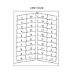
このような問題を解決するため、次に、ティースをテーパ状に形成した場合の例を図3に示す。ここで、図3は、上述した所定の傾斜角を設けることなく、ティースの軸線に対して垂直に巻回した場合のステータ巻線(比較例)を示す図である。図3の比較例に示されるように、ティースをテーパ状にしただけでは、まだ十分な程度には絶縁距離(相間距離)を均一にすることができない。すなわち、対向する平角線が同位相となるため、ステータ巻線30(平角線)の凸部と凸部、凹部と凹部が対向し、凸部と凸部とが対向する箇所では絶縁距離が短く、凹部と凹部とが対向する箇所では絶縁距離が長くなる。すなわち、絶縁距離が十分に均一にならない。よって、凸部と凸部とが対向する箇所の絶縁距離を大きく取ろうとした場合、ステータ巻線30の占積率が低下する。 In order to solve such a problem, an example in which the teeth are formed in a tapered shape is shown in FIG. Here, FIG. 3 is a diagram showing a stator winding (comparative example) when wound perpendicularly to the tooth axis without providing the above-described predetermined inclination angle. As shown in the comparative example of FIG. 3, the insulation distance (interphase distance) cannot be made uniform to a sufficient extent only by making the teeth tapered. That is, since the opposing rectangular wires have the same phase, the convex portion and the convex portion, the concave portion and the concave portion of the stator winding 30 (rectangular wire) face each other, and the insulating distance is short at the portion where the convex portion and the convex portion face each other. The insulation distance becomes longer at the location where the recess and the recess face each other. That is, the insulation distance is not sufficiently uniform. Therefore, when it is going to take the insulation distance of the location where a convex part and a convex part oppose large, the space factor of the stator winding 30 falls.
これに対して、本実施形態に係るステータ1によれば、図1,2に示されるように、ティース202をテーパ状に形成するとともに、ステータ巻線30を螺旋状に巻回することにより、絶縁距離がより均一になる。すなわち、ステータ巻線30(平角線)の凸部と凹部とが対向するように配置されることにより、絶縁距離(相間距離)がより均一になる。その結果、絶縁距離をより拡大することができ、又はステータ巻線30の占積率を向上させることもできる。
On the other hand, according to the
以上、説明したように、本実施形態によれば、先端部の断面積(又は径)が基端部の断面積(又は径)よりも小さくなるように、ティース202がテーパ状に形成されており、かつ、ステータ巻線30(平角線)が、ティース202の軸線と直行する平面に対して所定の傾斜角を持ちつつ、軸線方向に沿って螺旋状に巻回されている。そのため、隣り合うティース202に巻回された平角線(ステータ巻線30)それぞれの角部と角部とを、ティース202の軸線方向に沿って、互い違いに(互いに位相がずれるように)配置することができる。その結果、隣り合うティース202それぞれに巻回された平角線間(ステータ巻線30間)の距離(絶縁距離/相間距離)を、拡げることなくより均一にすることが可能となる。また、その結果、最短絶縁距離を拡大すること、又はステータ巻線の占積率を向上させることも可能となる。
As described above, according to the present embodiment, the
また、本実施形態によれば、ティース202の軸線方向に沿って、ティース202の外側面に階段状の段差が形成されており、軸線方向に沿った断面で見た場合に、両側面に形成された階段状の段差の位置(すなわち巻線位置)が、ティース202の軸線方向に対してオフセットされている(すなわち、ティース202の外側面に階段状の段差が螺旋状に形成されている)。そのため、当該階段状の段差に合わせて平角線を巻回することにより、隣り合うティース202に巻回された平角線(ステータ巻線30)それぞれの角部と角部とを、ティース202の軸線方向に沿って互い違いに、すなわち互いに位相がずれるように配置することが可能となる。
Further, according to the present embodiment, stepped steps are formed on the outer surface of the
また、本実施形態によれば、ティース202のテーパ角が、隣り合うティース202それぞれに巻回された平角線間(ステータ巻線30間)の距離が略一定となるように設定されているため、ステータ巻線30の占積率をより向上させることが可能となる。
Further, according to the present embodiment, the taper angle of the
さらに、本実施形態によれば、上記所定の傾斜角が、平角線の厚みに応じて、螺旋状に巻回される平角線を隙間なく巻回することができる角度に設定されているため、ステータ巻線30の占積率をより高めることが可能となる。 Furthermore, according to the present embodiment, the predetermined inclination angle is set to an angle at which the rectangular wire wound spirally can be wound without a gap depending on the thickness of the rectangular wire. The space factor of the stator winding 30 can be further increased.
本実施形態によれば、ティース202に巻回されるn層目(ただしnは自然数)の平角線が、ティース202の基端側から先端側に巻回され、n+1層目の平角線が、ティース202の先端側から基端側へ巻回される。そのため、例えば、層替わりを行う際に、斜め掛けなどを行うことなく、平角線を整列して連続的に巻回することができる。
According to the present embodiment, the rectangular wire of the nth layer (where n is a natural number) wound around the
以上、本発明の実施の形態について説明したが、本発明は、上記実施形態に限定されるものではなく種々の変形が可能である。例えば、上記実施形態では、ステータ1を、永久磁石式同期モータ(PM同期モータ)に適用したが、ステータ1は、例えば、誘導モータ(IMモータ)などの他の形式の電動モータ(電動機)にも適用することもできる。
Although the embodiment of the present invention has been described above, the present invention is not limited to the above embodiment, and various modifications can be made. For example, in the above embodiment, the
また、例えば、ティース202に形成される段差の数や、形状、大きさ等、及びスタータ巻線30(平角線)のサイズや巻線形状等は任意に設定することができ、上記実施形態には限られない。
Further, for example, the number, shape, size, and the like of the steps formed in the
1 ステータ
10 ステータコア
20 ステータセグメント
201 ヨーク
202 ティース
30 ステータ巻線(平角線)
DESCRIPTION OF
Claims (6)
前記ティースに巻回されたステータ巻線と、を備え、
前記ティースは、先端部の断面積が基端部の断面積よりも小さくなるようにテーパ状に形成されており、
前記ステータ巻線は、前記ティースの軸線と直行する平面に対して所定の傾斜角を持ちつつ、前記ティースの軸線方向に沿って、螺旋状に巻回されていることを特徴とするステータ。 An annular stator core having a plurality of teeth arranged at predetermined intervals along the circumferential direction and extending radially inward;
A stator winding wound around the teeth,
The teeth are formed in a tapered shape so that the cross-sectional area of the distal end portion is smaller than the cross-sectional area of the proximal end portion,
The stator winding is spirally wound along the axial direction of the teeth while having a predetermined inclination angle with respect to a plane orthogonal to the axial line of the teeth.
The rectangular wire of the nth layer (where n is a natural number) wound around the teeth is wound from the proximal end side to the distal end side of the teeth, and the rectangular wire of the (n + 1) th layer is derived from the distal end side of the teeth. The stator according to any one of claims 3 to 5, wherein the stator is wound toward an end side.
Priority Applications (1)
| Application Number | Priority Date | Filing Date | Title |
|---|---|---|---|
| JP2016050966A JP6747834B2 (en) | 2016-03-15 | 2016-03-15 | Stator |
Applications Claiming Priority (1)
| Application Number | Priority Date | Filing Date | Title |
|---|---|---|---|
| JP2016050966A JP6747834B2 (en) | 2016-03-15 | 2016-03-15 | Stator |
Publications (2)
| Publication Number | Publication Date |
|---|---|
| JP2017169310A true JP2017169310A (en) | 2017-09-21 |
| JP6747834B2 JP6747834B2 (en) | 2020-08-26 |
Family
ID=59909299
Family Applications (1)
| Application Number | Title | Priority Date | Filing Date |
|---|---|---|---|
| JP2016050966A Active JP6747834B2 (en) | 2016-03-15 | 2016-03-15 | Stator |
Country Status (1)
| Country | Link |
|---|---|
| JP (1) | JP6747834B2 (en) |
Cited By (1)
| Publication number | Priority date | Publication date | Assignee | Title |
|---|---|---|---|---|
| KR20170029003A (en) * | 2014-08-27 | 2017-03-14 | 제이에프이 스틸 가부시키가이샤 | Method for injecting pulverized coal into oxygen blast furnace |
-
2016
- 2016-03-15 JP JP2016050966A patent/JP6747834B2/en active Active
Cited By (1)
| Publication number | Priority date | Publication date | Assignee | Title |
|---|---|---|---|---|
| KR20170029003A (en) * | 2014-08-27 | 2017-03-14 | 제이에프이 스틸 가부시키가이샤 | Method for injecting pulverized coal into oxygen blast furnace |
Also Published As
| Publication number | Publication date |
|---|---|
| JP6747834B2 (en) | 2020-08-26 |
Similar Documents
| Publication | Publication Date | Title |
|---|---|---|
| JP5314908B2 (en) | Rotating electric machine stator and rotating electric machine | |
| US20150042196A1 (en) | Rotating electrical machine and method of manufacturing the same | |
| NZ591332A (en) | Method for manufacturing a stator for an energy converting apparatus with stator windings which increase in cross-sectional area radially outwards | |
| CN108141082B (en) | Rotating electrical machine | |
| JP5641341B2 (en) | Armature | |
| TW201445855A (en) | Stator and electric motor using the same | |
| JP2015154582A (en) | Stator for three-phase rotary electric machine | |
| KR20140018780A (en) | Rotary electric machine | |
| JP2009011064A (en) | Stator of rotating electric machine, and manufacturing method thereof | |
| JP2008245489A (en) | Stator for electrical rotating machine | |
| JP6293576B2 (en) | Stator for rotating electrical machine | |
| US9373983B2 (en) | Rotating electrical machine | |
| JP2010506549A (en) | Stator for rotating electrical machine | |
| US10153673B2 (en) | Production method for rotating electrical machine | |
| CN109478813B (en) | Axial gap type rotating electric machine | |
| JP2015139243A (en) | Rotary electric machine stator | |
| JP2014036559A (en) | Stator for rotary electric machine | |
| US20220263356A1 (en) | Motor | |
| JP6210705B2 (en) | Rotating electric machine and stator used therefor | |
| JP2017046508A (en) | Rotary electric machine and manufacturing method therefor | |
| JP4986974B2 (en) | Stator | |
| JP2009011151A (en) | Stator of rotating electric machine | |
| JP2017169310A (en) | Stator | |
| JP2017118640A (en) | Electric motor having wave winding coil and manufacturing method therefor | |
| US10128712B2 (en) | Rotating electrical machine and method of manufacturing the same |
Legal Events
| Date | Code | Title | Description |
|---|---|---|---|
| A621 | Written request for application examination |
Free format text: JAPANESE INTERMEDIATE CODE: A621 Effective date: 20181211 |
|
| A131 | Notification of reasons for refusal |
Free format text: JAPANESE INTERMEDIATE CODE: A131 Effective date: 20191001 |
|
| A977 | Report on retrieval |
Free format text: JAPANESE INTERMEDIATE CODE: A971007 Effective date: 20190927 |
|
| A521 | Request for written amendment filed |
Free format text: JAPANESE INTERMEDIATE CODE: A523 Effective date: 20191127 |
|
| A131 | Notification of reasons for refusal |
Free format text: JAPANESE INTERMEDIATE CODE: A131 Effective date: 20200128 |
|
| A521 | Request for written amendment filed |
Free format text: JAPANESE INTERMEDIATE CODE: A523 Effective date: 20200327 |
|
| TRDD | Decision of grant or rejection written | ||
| A01 | Written decision to grant a patent or to grant a registration (utility model) |
Free format text: JAPANESE INTERMEDIATE CODE: A01 Effective date: 20200714 |
|
| A61 | First payment of annual fees (during grant procedure) |
Free format text: JAPANESE INTERMEDIATE CODE: A61 Effective date: 20200806 |
|
| R150 | Certificate of patent or registration of utility model |
Ref document number: 6747834 Country of ref document: JP Free format text: JAPANESE INTERMEDIATE CODE: R150 |
|
| R250 | Receipt of annual fees |
Free format text: JAPANESE INTERMEDIATE CODE: R250 |