JP2017167883A - Monitoring system and monitoring method - Google Patents
Monitoring system and monitoring method Download PDFInfo
- Publication number
- JP2017167883A JP2017167883A JP2016053530A JP2016053530A JP2017167883A JP 2017167883 A JP2017167883 A JP 2017167883A JP 2016053530 A JP2016053530 A JP 2016053530A JP 2016053530 A JP2016053530 A JP 2016053530A JP 2017167883 A JP2017167883 A JP 2017167883A
- Authority
- JP
- Japan
- Prior art keywords
- health monitoring
- monitoring system
- physical quantity
- devices
- structural health
- Prior art date
- Legal status (The legal status is an assumption and is not a legal conclusion. Google has not performed a legal analysis and makes no representation as to the accuracy of the status listed.)
- Granted
Links
Images

Classifications
-
- H—ELECTRICITY
- H04—ELECTRIC COMMUNICATION TECHNIQUE
- H04W—WIRELESS COMMUNICATION NETWORKS
- H04W84/00—Network topologies
- H04W84/18—Self-organising networks, e.g. ad-hoc networks or sensor networks
-
- G—PHYSICS
- G08—SIGNALLING
- G08C—TRANSMISSION SYSTEMS FOR MEASURED VALUES, CONTROL OR SIMILAR SIGNALS
- G08C17/00—Arrangements for transmitting signals characterised by the use of a wireless electrical link
- G08C17/02—Arrangements for transmitting signals characterised by the use of a wireless electrical link using a radio link
Landscapes
- Engineering & Computer Science (AREA)
- Computer Networks & Wireless Communication (AREA)
- Signal Processing (AREA)
- Physics & Mathematics (AREA)
- General Physics & Mathematics (AREA)
- Arrangements For Transmission Of Measured Signals (AREA)
- Testing Of Devices, Machine Parts, Or Other Structures Thereof (AREA)
- Selective Calling Equipment (AREA)
Abstract
【課題】従来の構造ヘルスモニタリングシステムでは、多数のセンサ装置からの計測データが1つの計算機または中継装置に収集される場合に、センサ装置の通信距離が長くなる結果、通信時の消費電力が著しく増加してしまう。【解決手段】複数の構造物のそれぞれに対して少なくとも1つずつ設置され、対象となる構造物の物理量を検出する複数のセンサ装置と、複数の構造物のうち少なくとも1つの構造物をそれぞれ含む構造物群毎に対応付けて設けられ、対象となる構造物群に含まれる各構造物に設置された各センサ装置が検出した物理量のデータを無線によりそれぞれ収集する複数の収集装置と、複数の収集装置に接続され、複数の収集装置により収集された物理量のデータを複数の収集装置から受信するデータ処理装置と、を備える構造ヘルスモニタリングシステム、および構造ヘルスモニタリング方法を提供する。【選択図】図1In a conventional structural health monitoring system, when measurement data from a large number of sensor devices is collected in one computer or relay device, the communication distance of the sensor device is increased, resulting in a significant increase in power consumption during communication. It will increase. A plurality of sensor devices installed at least one for each of a plurality of structures to detect a physical quantity of the target structure and at least one of the plurality of structures are included. A plurality of collection devices that are provided in association with each structure group, and each collect wirelessly the physical quantity data detected by each sensor device installed in each structure included in the target structure group, and a plurality of collection devices A structural health monitoring system and a structural health monitoring method are provided that include a data processing device that is connected to a collection device and receives physical quantity data collected by a plurality of collection devices from the plurality of collection devices. [Selection] Figure 1
Description
本発明は、構造ヘルスモニタリングシステム、収集装置および構造ヘルスモニタリング方法に関する。 The present invention relates to a structural health monitoring system, a collection device, and a structural health monitoring method.
構造ヘルスモニタリングシステムは、建物などの構造物の振動を監視して構造物の損傷、経年劣化等の構造性能を診断する。構造ヘルスモニタリングシステムは、例えば、構造物の振動を検出する加速度センサ等を含むセンサ装置、センサ装置による計測データを解析する計算機を含んで構築される(例えば、特許文献1、2)。
The structural health monitoring system monitors structural vibrations such as buildings and diagnoses structural performance such as structural damage and aging. A structural health monitoring system is constructed including, for example, a sensor device including an acceleration sensor that detects vibration of a structure, and a computer that analyzes measurement data from the sensor device (for example,
このような構造ヘルスモニタリングシステムでは、各センサ装置が計測データを有線又は無線で送信することで、計算機、または中継装置が複数のセンサ装置による計測データを収集している。
[特許文献1]特開2015−111091号公報
[特許文献2]特開2014−174715号公報
In such a structural health monitoring system, each sensor device transmits measurement data by wire or wireless, so that a computer or a relay device collects measurement data from a plurality of sensor devices.
[Patent Document 1] JP-A-2015-111091 [Patent Document 2] JP-A-2014-174715
しかしながら、従来の構造ヘルスモニタリングシステムでは、対象とする構造物の配置によっては、多数のセンサ装置から1つの計算機または中継装置へと計測データを無線送信する場合に、センサ装置の通信距離が長くなる結果、通信時の消費電力が著しく増加してしまう。 However, in the conventional structural health monitoring system, depending on the arrangement of the target structure, when the measurement data is wirelessly transmitted from a large number of sensor devices to one computer or relay device, the communication distance of the sensor device becomes long. As a result, power consumption during communication is significantly increased.
本発明の第1の態様においては、複数の構造物のそれぞれに対して少なくとも1つずつ設置され、対象となる構造物の物理量を検出する複数のセンサ装置と、複数の構造物のうち少なくとも1つの構造物をそれぞれ含む構造物群毎に対応付けて設けられ、対象となる構造物群に含まれる各構造物に設置された各センサ装置が検出した物理量のデータを無線によりそれぞれ収集する複数の収集装置と、複数の収集装置に接続され、複数の収集装置により収集された物理量のデータを複数の収集装置から受信するデータ処理装置と、を備える構造ヘルスモニタリングシステム、収集装置および構造ヘルスモニタリング方法を提供する。 In the first aspect of the present invention, at least one sensor is installed for each of the plurality of structures and detects a physical quantity of the target structure, and at least one of the plurality of structures. A plurality of units each of which collects data of physical quantities detected by each sensor device installed in each structure included in each target structure group in association with each structure group including two structures. Structural health monitoring system, collection device, and structural health monitoring method comprising: a collection device; and a data processing device connected to the plurality of collection devices and receiving physical quantity data collected by the plurality of collection devices from the plurality of collection devices I will provide a.
なお、上記の発明の概要は、本発明の特徴の全てを列挙したものではない。また、これらの特徴群のサブコンビネーションもまた、発明となりうる。 The summary of the invention does not enumerate all the features of the present invention. In addition, a sub-combination of these feature groups can also be an invention.
以下、発明の実施の形態を通じて本発明を説明するが、以下の実施形態は特許請求の範囲にかかる発明を限定するものではない。また、実施形態の中で説明されている特徴の組み合わせの全てが発明の解決手段に必須であるとは限らない。 Hereinafter, the present invention will be described through embodiments of the invention, but the following embodiments do not limit the invention according to the claims. In addition, not all the combinations of features described in the embodiments are essential for the solving means of the invention.
[構造ヘルスモニタリングシステムの概要]
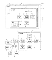
図1は、本実施形態に係る構造ヘルスモニタリングシステム1を示すブロック図である。構造ヘルスモニタリングシステム1は、複数の構造物101の構造性能を診断するものであり、複数のセンサ装置2と、複数の収集装置3と、データ処理装置4と、診断サーバ5と、雨量計6と、風向風速計7と、温度計8とを備える。なお、雨量計6、風向風速計7、温度計8は、センサ装置2と一体型としてもよい。
[Outline of structural health monitoring system]
FIG. 1 is a block diagram showing a structural
ここで、複数の構造物101は、本実施の形態においては、一例として建物である。建物とは、それぞれ建物、すなわち、居住、オフィス、店舗、工場、倉庫などの目的で利用される、土地に定着した建造物であって、屋根および周壁を有するものである。この構造物101は、例えば、道路102(図3参照)に面して設けられている。
Here, the plurality of
複数のセンサ装置2は、複数の構造物101のそれぞれに対して少なくとも1つずつ、好ましくは複数設置され、対象となる構造物101の物理量、例えば、構造物が地震などで振動するときの加速度および構造物の傾き等を検出する。複数のセンサ装置2が1つの構造物101に対して設置される場合には、これらのセンサ装置2は、例えば低層階(例えば1階)、及び高層階(例えば最上階)に設けられ、好ましくは、さらに1以上の中層階、ならびに/または、地盤および地下などにも設けられる。
The plurality of
各センサ装置2は、例えば、クロック部20、メモリ23、センサ部24、データ処理部25および通信部26を有しており、好ましくは、さらに独立の電源200を有している。
Each
クロック部20は、時計機能を持った回路であり、内部に時刻データを保持すると共に、クロック信号を装置内の各部、例えばセンサ部24、データ処理部25、通信部26等に出力する。各センサ装置2のクロック部20は、それぞれの時刻データが同期した状態となるよう維持される。
The
メモリ23は、センサ装置2の各種機能を実現するためのプログラムおよびデータを記憶する。例えば、メモリ23は、センサ部24により検出された物理量データを記憶する。
The
センサ部24は、対象となる構造物101についての上述の物理量を検出する。例えば、センサ部24は、構造物が地震などで振動するときの加速度を検出する加速度センサである。一例として、このセンサは、一つのシリコン基板、ガラス基板、有機材料などの上に集積化されたMEMSデバイスであってよく、更に言えば、静電容量型のセンサであってもよい。以上のセンサ部24は、検出した物理量データをデータ処理部25に供給する。
The
データ処理部25は、一例としてマイクロコントローラまたはマイクロプロセッサを有し、種々のデータ処理を行う。例えば、データ処理部25は、センサ部24から受信した物理量データをメモリ23に記憶させる。また、データ処理部25は、物理量データをメモリ23から読み出し、収集装置3に送信すべく通信部26に供給する。
The
通信部26は、複数の収集装置3のうち対応する一の収集装置3と無線通信する。例えば、通信部26は、メモリ23内の物理量データをデータ処理部25から受け取って、収集装置3に送信する。
The
以上の通信部26は、任意の通信規格による無線通信によって収集装置3と通信してよく、好ましくは近距離無線通信によって通信する。近距離無線通信としては、2.5GHz帯を使用するBluetooth(登録商標)のクラス1(通信距離約100m)、クラス2(通信距離約10m)またはクラス3(通信距離約1m)、2.5GHz帯または5GHz帯を使用するWi−fi(通信距離数十〜数百m)、赤外波長帯を使用する赤外線通信(通信距離約1m未満)、または、27MHz帯、150MHz帯、400MHz帯、900MHz帯、920MHz帯、950MHz帯または50GHz帯を使用する簡易無線通信などを用いることができる。本実施の形態においては、通信部26は、920MHz帯の簡易無線通信により収集装置3と通信する。
The
電源200は、環境エネルギーによって発電し、電力を蓄積すると共にセンサ装置2の各部に供給する。環境エネルギーとしては、例えば光、風力、および/または、構造物の常時振動などを用いることができる。例えば、電源200は、太陽光などの自然光および/または照明装置による照明光などの光を受けて発電するソーラーパネル201を有する。このソーラーパネル201は、センサ装置2の筐体に対して一体的に設けられてもよいし、別体的に設けられてもよい。
The
複数の収集装置3は、少なくとも1つの構造物101を含む構造物群1000に対応付けてそれぞれ設けられている。例えば、複数の収集装置3は、1つのみの構造物101を含む構造物群1000に対応付けてそれぞれ設けられている、つまり、複数の構造物101のそれぞれに1対1に対応付けて設けられている。但し、複数の収集装置3は、道路102を挟んだ2つの構造物101を含む構造物群1000に対応付けてそれぞれ設けられてもよい。
The plurality of collecting
複数の収集装置3のそれぞれは、対応する構造物群1000に含まれる各構造物101から100m以内、好ましくは50m以内に設置されてよい。なお、通常の場合、構造物群1000同士の間の最小距離は、それぞれの構造物群1000に設置された各センサ装置2と、当該構造物群1000に対応する収集装置3との距離のうちの最大の距離よりも長い。つまり、構造物群1000同士の間の最小距離は、それぞれの構造物群1000に設置された各センサ装置2が物理量のデータを無線送信する最大無線送信距離よりも長くなっている。これにより、離れた構造物群1000の間で収集装置3を共有した場合に、センサ装置2の無線通信距離が長くなってセンサ装置2の電力消費量が増えてしまうのを防ぐことができる。また、一の構造物群1000に設置されたセンサ装置2からの無線送信と、他の構造物群1000に設置されたセンサ装置2からの無線送信との輻輳を回避することも可能となる。
Each of the plurality of collecting
各収集装置3は、対象となる構造物群1000に含まれる各構造物101に設置された各センサ装置2から無線送信される物理量データを無線によりそれぞれ収集するようになっており、クロック部30、時刻受信部31は、無線通信部32、メモリ33、制御部35およびデータ送信部36を有している。
Each
クロック部30は、時計機能を持った回路であり、内部に時刻データを保持すると共に、クロック信号を装置内の各部、例えば制御部35に出力する。なお、クロック部30内の時刻データは、後述のように制御部35によって外部の基準時刻に対して同期される。
The clock unit 30 is a circuit having a clock function, holds time data therein, and outputs a clock signal to each unit in the apparatus, for example, the
時刻受信部31は、外部機器から時刻データを受信して制御部35に供給する。一例として、時刻受信部31は、GPS(Global Positioning System)からGPS電波を受信することで、この電波に含まれる時刻データを受信してよい。
The
無線通信部32は、複数のセンサ装置2の通信部26と無線通信する。例えば、無線通信部32は、複数のセンサ装置2から物理量データを収集して制御部35に供給する。
The
メモリ33は、収集装置3の各種機能を実現するためのプログラムおよびデータを記憶する。例えば、メモリ33は、複数のセンサ装置2から収集した物理量データを記憶する。
The
制御部35は、一例としてマイクロコントローラまたはマイクロプロセッサを有し、各部の制御を行う。例えば、制御部35は、クロック部30を外部の基準時刻に対して同期させる。一例として、制御部35は、時刻受信部31にGPS電波を受信させ、この電波に含まれる時刻データを時刻受信部31から受信してクロック部30に供給することで、この時刻データにクロック部30内の時刻データを合わせる。
The
また、制御部35は、無線通信部32が受信した物理量データを、送信元のセンサ装置2を識別するための識別子に対応付けてメモリ33に記憶させる。そして、制御部35は、物理量データをメモリ33から読み出して識別子と共にデータ送信部36に供給する。
In addition, the
データ送信部36は、制御部35から供給される物理量データを、収集装置3に接続されたデータ処理装置4へと有線または無線により送信する。
The
データ処理装置4は、複数の収集装置3に接続されている。このデータ処理装置4は、複数の収集装置3により収集された物理量のデータを、複数の収集装置3から受信して、構造物101の物理量データに対する種々の処理を行う。例えば、データ処理装置4は、受信した物理量データを構造物101ごと、かつ、センサ装置2ごとに振り分けて診断サーバ5に提供する。
The
診断サーバ5は、データ処理装置4からの物理量データを構造物101ごとに解析することで、構造物101の構造性能を診断する。例えば、診断サーバ5は、センサ装置2で検出された加速度データを定期的に解析して構造物101の共振周波数を算出し、その経年変化より構造物の構造性能を診断してもよい。また、診断サーバ5は、加速度データを解析して複数のセンサ装置2のそれぞれが設けられた階層の変位を算出し、その経年変化より構造物の構造性能を診断してもよい。より具体的には、診断サーバ5は、最大加速度、最大層間変形角(地震時での構造物の水平変位を階高で割った値の最大値。例えば加速度検出値の2回積分値)、固有振動数、および、モード(固有振動数で振動する時の振幅形状)等についての算出結果および/またはその変化から構造性能(剛性の低下)を診断するとよい。また、診断サーバ5は、診断結果を表示して保守業者にメンテナンスを促してもよいし、構造物101の利用者に危険を報知してもよい。なお、この診断サーバ5は、データ処理装置4と一体化されてもよい。
The
なお、データ処理装置4および診断サーバ5は、データ解析結果を履歴として管理してよいし、センサ部24の設定およびその履歴も管理してよい。更に、データ処理装置4および診断サーバ5は、これらのデータと共に、雨量計6、風向風速計7および温度計8の測定データも保持してよい。
The
ここで、雨量計6は、構造物群1000が含まれる地域の降水量を計測するものである。また、風向風速計7は、構造物群1000が含まれる地域の風向きおよび風速を計測するものである。また、温度計8は、構造物群1000が含まれる地域の気温を計測するものである。これらの雨量計6、風向風速計7および温度計8は、計測を常時行ってもよいし、センサ装置2による後述の間欠的な観測期間に同期して行ってもよい。また、雨量計6、風向風速計7および温度計8は、測定データと、測定時の時刻データとを対応付けて診断サーバ5に送信してよい。
Here, the rain gauge 6 measures the amount of precipitation in an area including the
[構造ヘルスモニタリングシステムの動作]
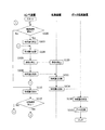
続いて、構造ヘルスモニタリングシステム1の動作について説明する。図2は、構造ヘルスモニタリングシステム1の動作を示すフローチャートである。
[Operation of structural health monitoring system]
Next, the operation of the structural
まず、センサ装置2は、クロック部20を参照し、間欠的な観測期間が開始するか否かを判定する(S100)。例えば、間欠的な観測期間とは、1時間ごとに3分などであってよい。一例として、センサ装置2は、クロック部20で示される時刻が正時、つまり毎時の0分0秒である場合に観測期間が開始すると判定する。
First, the
S100で観測期間が開始すると判定した場合(S100;Yes)には、センサ部24は、観測期間が継続している間、構造物101の物理量の検出を継続して行う(S102)。また、センサ部24は、検出した物理量をデータ処理部25に供給する。なお、センサ部24は、アナログの物理量データに対する変調、復調およびゼロ点調整などを行ってから、物理量データをデータ処理部25に供給してよい。このように間欠的な観測期間に物理量の検出を行うことにより、電源200の消費電力が低減される。
If it is determined that the observation period starts in S100 (S100; Yes), the
次に、データ処理部25が物理量データをメモリ23に記録する(S104)。例えば、データ処理部25は、センサ部24から受信したアナログの物理量データをAD変換してメモリ23に記憶させてよい。また、データ処理部25は、センサ部24から受信した物理量データをクロック部20から受信した時刻データと対応付けてメモリ23に記憶させてよい。以上のS102、S104の処理により、間欠的な各観測期間において検出される物理量がメモリ23に記録される。
Next, the
次に、センサ装置2および収集装置3は、互いの間で通信を確立する(S106、S120)。例えば、センサ装置2は、クロック部20を参照し、当該センサ装置2に対して収集装置3から予め割り当てられたタイミングで収集装置3と通信を確立してよい。
Next, the
次に、センサ装置2が、検出した物理量データを収集装置3に送信する(S108)。例えば、データ処理部25が、物理量データおよび時刻データの組み合わせをメモリ23から読み出し、当該センサ装置2の識別子とともに通信部26に供給する。そして、通信部26が、供給された物理量データなどを収集装置3に送信する。収集装置3による物理量データの受信以降の処理については、説明を後述する。
Next, the
以上のS106〜S108の処理により、複数のセンサ装置2のそれぞれは、測定した物理量のデータを、当該センサ装置2に割り当てられた識別情報に応じたタイミングで、収集装置3に送信する。そして、S108の処理が終了したら、センサ装置2は、上述のS100に処理を移行する。
Through the processes of S106 to S108 described above, each of the plurality of
一方、上述のS100において観測期間が開始しないと判定した場合(S100;No)には、突発事象(例えば、地震や台風などの災害、および交通事故等)の発生の有無を監視すべくセンサ部24が物理量の検出を行う(S110)。例えば、センサ部24は、一の継続時間(例えば10ms)内に継続して物理量を検出してもよいし、瞬間的に物理量を1回検出してもよい。
On the other hand, when it is determined that the observation period does not start in S100 described above (S100; No), the sensor unit monitors whether or not a sudden event (for example, a disaster such as an earthquake or a typhoon or a traffic accident) has occurred. 24 detects a physical quantity (S110). For example, the
次に、センサ部24は、突発事象が発生したか否かを判定する(S112)。例えば、センサ部24は、S110で検出した物理量が基準閾値よりも大きい場合に突発事象の発生を示すと判断してよい。また、センサ部24は、検出した物理量が直前の物理量に対して基準割合よりも大きく変化している場合に、突発事象の発生を示すと判断してもよい。
Next, the
このS112において突発事象が発生しないと判定された場合(S112;No)には、センサ装置2は上述のS100に処理を戻す。これにより、観測期間が開始しない限り(S100;No)、S110の処理が繰り返し行われることになる。この場合には、S110の処理は基準間隔ごと(例えば5秒ごと)に行われてよい。
When it is determined in S112 that no sudden event occurs (S112; No), the
また、S112において突発事象が発生したと判定された場合(S112;Yes)には、センサ装置2は上述のS104に処理を移行する。これにより、間欠的な観測期間外においてもS110で物理量の検出が行われ、検出した物理量が突発事象の発生を示すとS112で判断されることに応じて物理量がメモリ23に記録される。
If it is determined in S112 that a sudden event has occurred (S112; Yes), the
なお、センサ装置2は、上述のS100の処理で観測期間が開始していないと判定された場合(S100;No)にS110,S112の処理を行わずにS100の処理を繰り返してもよい。また、センサ装置2は、上述のS100、S112の処理を行わずにS102(またはS110)〜S108を常時行ってもよい。
In addition, the
ここで、上述のS108の処理により各センサ装置2から物理量データが送信されると、収集装置3はこれらの物理量データをそれぞれ受信して収集する(S122)。例えば、収集装置3の制御部35は、無線通信部32が受信した物理量データをメモリ33に記憶させてよい。また、センサ装置2から物理量データ、時刻データおよびセンサ装置2の識別子が対応付けて送信される場合には、制御部35は、これらの組み合わせをメモリ33に記憶させて良い。
Here, when physical quantity data is transmitted from each
次に、収集装置3は、複数のセンサ装置2から収集された物理量データをデータ処理装置4に送信する(S124)。例えば、収集装置3の制御部35は、メモリ33から物理量、時刻データおよびセンサ装置2の識別子の組み合わせをメモリ33から読みだして、データ送信部36に供給する。そして、データ送信部36は、供給された物理量データなどをデータ処理装置4に送信する。
Next, the
次に、データ処理装置4は、複数の収集装置3からの物理量データを受信する(S130)。例えば、データ処理装置4は、収集装置3から受信した物理量データを内部の記憶装置に記憶させてよい。また、収集装置3から物理量データ、時刻データおよびセンサ装置2の識別子が対応付けて送信される場合には、データ処理装置4は、これらの組み合わせを記憶させて良い。
Next, the
そして、データ処理装置4は、受信した物理量データに対するデータ処理を行う(S132)。例えば、データ処理装置4は、受信した物理量データを構造物101ごと、かつ、センサ装置2ごとに振り分けて診断サーバ5に提供する。但し、データ処理装置4は、物理量データをセンサ装置2ごとに解析することで、構造物101の構造性能を診断してもよい。
Then, the
以上の構造ヘルスモニタリングシステム1によれば、少なくとも1つの構造物101をそれぞれ含む構造物群1000毎に対応付けて設けられた収集装置3が、対象となる構造物群1000に含まれる各構造物101に設置された各センサ装置2が検出した物理量のデータを無線によりそれぞれ収集するので、センサ装置2の通信距離が長くなって通信時の消費電力が著しく増加してしまうのを防止することができる。
According to the structural
[構造ヘルスモニタリングシステムの設置例]
図3は、本実施形態に係る構造ヘルスモニタリングシステム1の設置例を示す図である。この図に示すように、本実施形態における構造ヘルスモニタリングシステム1のセンサ装置2は、高層ビルの建物である構造物101の低層階、中層階および高層階にそれぞれ設置されている(地下に設置される場合もある)。また、これらのセンサ装置2と通信可能な状態で、1つの収集装置3が設置されている。なお、図3では、1つの構造物101を含む構造物群1000に1つの収集装置3が対応付けられているが、複数の構造物101を含む構造物群1000に1つの収集装置3が対応付けられてもよい。
[Example of structural health monitoring system installation]
FIG. 3 is a diagram illustrating an installation example of the structural
[構造ヘルスモニタリングシステムの設置例の変形例(1)]
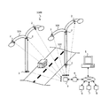
図4は、変形例(1)における構造ヘルスモニタリングシステム1の設置例を示す図である。
[Modified example of installation example of structural health monitoring system (1)]
FIG. 4 is a diagram illustrating an installation example of the structural
この図に示すように、本変形例(1)における構造ヘルスモニタリングシステム1のセンサ装置2は、複数の構造物101のうちの第1構造物105と、第1構造物105に対して道路102の向かい側にある第2構造物106とにそれぞれ設置されている。
As shown in this figure, the
ここで、第1構造物105および第2構造物106は、道路付帯構造物である。道路付帯構造物とは、道路102の表面、上部、側部に設けられる構造物であり、例えば信号、案内表示板、照明設備、ガードレールなどである。本変形例(1)において、第1構造物105および第2構造物106は、道路102の照明設備となっている。
Here, the
センサ装置2は、第1構造物105および第2構造物106の土台部分と、支柱上部と、照明部の近傍とに設置されている。なお、支柱上部および照明部近傍に設置されたセンサ装置2のソーラーパネル201は、一日当たりの受光量が最も多くなるよう、太陽光の他、照明部からの照明光を受光可能な向きに向けられている。
The
また、複数の収集装置3のうちの一の収集装置3は、これらの第1構造物105および第2構造物106を含む構造物群1000に対応して設けられ、第1構造物105および第2構造物106のセンサ装置2と通信可能となっている。
One of the plurality of collecting
[構造ヘルスモニタリングシステムの設置例の変形例(2)]
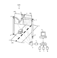
図5は、変形例(2)における構造ヘルスモニタリングシステム1の設置例を示す図である。
[Modified example of installation of structural health monitoring system (2)]
FIG. 5 is a diagram illustrating an installation example of the structural
この図に示すように、本変形例(2)における構造ヘルスモニタリングシステム1のセンサ装置2は、道路102の一方向への車線に設けられた第1構造物107と、反対車線における第1構造物107の対応位置に設けられた第2構造物108とにそれぞれ設置されている。例えば、本変形例において第1構造物107および第2構造物108は、道路付帯構造物であり、一例として、道路の案内表示板である。
As shown in this figure, the
また、複数の収集装置3のうちの一の収集装置3は、これらの第1構造物107および第2構造物108に対応して設けられ、第1構造物107および第2構造物108のセンサ装置2と通信可能となっている。
One of the plurality of collecting
なお、上記の実施形態および変形例(1)、(2)では、構造物101、105〜108を建物または道路付帯構造物として説明したが、他の構造物であってもよい。ここで、他の構造物は、例えば複数の材料や部材などから構成され、基礎などにより重量を支えられた構造で造作されたものであってよい。一例として、構造物は、空港の管制塔、飛行場灯台、高速道路、駅、鉄道のレール、鉄道信号、港湾のクレーン、プラント(石油化学、製鉄)、鋼橋、ダム、堤防、盛土、法面、土手などであってよい。
In addition, in said embodiment and modification (1), (2), although the
以上、本発明を実施の形態を用いて説明したが、本発明の技術的範囲は上記実施の形態に記載の範囲には限定されない。上記実施の形態に、多様な変更または改良を加えることが可能であることが当業者に明らかである。その様な変更または改良を加えた形態も本発明の技術的範囲に含まれ得ることが、特許請求の範囲の記載から明らかである。 As mentioned above, although this invention was demonstrated using embodiment, the technical scope of this invention is not limited to the range as described in the said embodiment. It will be apparent to those skilled in the art that various modifications or improvements can be added to the above-described embodiment. It is apparent from the scope of the claims that the embodiments added with such changes or improvements can be included in the technical scope of the present invention.
特許請求の範囲、明細書、および図面中において示した装置、システム、プログラム、および方法における動作、手順、ステップ、および段階等の各処理の実行順序は、特段「より前に」、「先立って」等と明示しておらず、また、前の処理の出力を後の処理で用いるのでない限り、任意の順序で実現しうることに留意すべきである。特許請求の範囲、明細書、および図面中の動作フローに関して、便宜上「まず、」、「次に、」等を用いて説明したとしても、この順で実施することが必須であることを意味するものではない。 The order of execution of each process such as operations, procedures, steps, and stages in the apparatus, system, program, and method shown in the claims, the description, and the drawings is particularly “before” or “prior to”. It should be noted that the output can be realized in any order unless the output of the previous process is used in the subsequent process. Regarding the operation flow in the claims, the description, and the drawings, even if it is described using “first”, “next”, etc. for convenience, it means that it is essential to carry out in this order. It is not a thing.
1 構造ヘルスモニタリングシステム、2 センサ装置、3 収集装置、4 データ処理装置、5 診断サーバ、6 雨量計、7 風向風速計、8 温度計、20 クロック部、23 メモリ、24 センサ部、25 データ処理部、26 通信部、30 クロック部、31 時刻受信部、32 無線通信部、33 メモリ、35 制御部、36 データ送信部、101 構造物、102 道路、105 構造物、106 構造物、107 構造物、108 構造物、200 電源、201 ソーラーパネル、1000 構造物群 1 structural health monitoring system, 2 sensor device, 3 collection device, 4 data processing device, 5 diagnostic server, 6 rain gauge, 7 wind direction anemometer, 8 thermometer, 20 clock unit, 23 memory, 24 sensor unit, 25 data processing Unit, 26 communication unit, 30 clock unit, 31 time reception unit, 32 wireless communication unit, 33 memory, 35 control unit, 36 data transmission unit, 101 structure, 102 road, 105 structure, 106 structure, 107 structure , 108 structure, 200 power supply, 201 solar panel, 1000 structure group
本発明は、モニタリングシステムおよびモニタリング方法に関する。 The present invention relates to a monitoring system and monitoring method.
複数の収集装置3のそれぞれは、対応する構造物群1000に含まれる各構造物101から100m以内、好ましくは50m以内に設置されてよい。なお、通常の場合、構造物群1000同士の間の最小距離は、それぞれの構造物群1000に設置された各センサ装置2と、当該構造物群1000に対応する収集装置3との距離のうちの最大の距離よりも長い。つまり、構造物群1000同士の間の最小距離は、それぞれの構造物群1000に設置された各センサ装置2が物理量のデータを無線送信する最大無線送信距離よりも長くなっている。これにより、一の構造物群1000に設置されたセンサ装置2からの無線送信と、他の構造物群1000に設置されたセンサ装置2からの無線送信との輻輳を回避することが可能となる。
Each of the plurality of collecting
Claims (16)
前記複数の構造物のうち少なくとも1つの構造物をそれぞれ含む構造物群毎に対応付けて設けられ、対象となる構造物群に含まれる各構造物に設置された各センサ装置が検出した物理量のデータを無線によりそれぞれ収集する複数の収集装置と、
前記複数の収集装置に接続され、前記複数の収集装置により収集された物理量のデータを前記複数の収集装置から受信するデータ処理装置と、
を備える構造ヘルスモニタリングシステム。 A plurality of sensor devices installed at least one for each of the plurality of structures and detecting physical quantities of the target structure;
A physical quantity detected by each sensor device installed in each structure included in each structure group provided in association with each structure group including at least one structure among the plurality of structures. A plurality of collecting devices for collecting data wirelessly;
A data processing device connected to the plurality of collection devices and receiving physical quantity data collected by the plurality of collection devices from the plurality of collection devices;
Structural health monitoring system with.
前記構造物群に含まれる各構造物に対して少なくとも1つずつ設置されて対象となる構造物の物理量を検出する複数のセンサ装置から、検出した物理量のデータを無線により収集する無線通信部と、
収集した物理量のデータを記憶するメモリと、
前記メモリに記憶された物理量のデータを、複数の前記収集装置に接続されるデータ処理装置へと送信するデータ送信部と、
を備える収集装置。 A collection device provided in association with a structure group including at least one structure,
A wireless communication unit that wirelessly collects data of detected physical quantities from a plurality of sensor devices that are installed at least one for each structure included in the structure group and detect physical quantities of the target structure; ,
A memory for storing collected physical quantity data;
A data transmission unit that transmits data of a physical quantity stored in the memory to a plurality of data processing devices connected to the collection device;
A collection device comprising:
前記複数の構造物のうち少なくとも1つの構造物をそれぞれ含む構造物群毎に対応付けて設けられた複数の収集装置により、対象となる構造物群に含まれる各構造物に設置された各センサ装置が検出した物理量のデータを無線でそれぞれ収集する段階と、
前記複数の収集装置に接続されたデータ処理装置により、前記複数の収集装置により収集された物理量のデータを前記複数の収集装置から受信する段階と、
を備える構造ヘルスモニタリング方法。 Detecting each physical quantity of the target structure with a plurality of sensor devices installed at least one for each of the plurality of structures;
Each sensor installed in each structure included in the target structure group by a plurality of collecting devices provided in association with each structure group including at least one structure among the plurality of structures. Wirelessly collecting physical quantity data detected by the device;
Receiving physical quantity data collected by the plurality of collection devices from the plurality of collection devices by a data processing device connected to the plurality of collection devices;
A structural health monitoring method comprising:
Priority Applications (2)
| Application Number | Priority Date | Filing Date | Title |
|---|---|---|---|
| JP2016053530A JP6032380B1 (en) | 2016-03-17 | 2016-03-17 | Monitoring system and monitoring method |
| CN201710111244.0A CN107205285A (en) | 2016-03-17 | 2017-02-28 | Structural healthy monitoring system, collection device and structure health monitoring method |
Applications Claiming Priority (1)
| Application Number | Priority Date | Filing Date | Title |
|---|---|---|---|
| JP2016053530A JP6032380B1 (en) | 2016-03-17 | 2016-03-17 | Monitoring system and monitoring method |
Publications (2)
| Publication Number | Publication Date |
|---|---|
| JP6032380B1 JP6032380B1 (en) | 2016-11-30 |
| JP2017167883A true JP2017167883A (en) | 2017-09-21 |
Family
ID=57419771
Family Applications (1)
| Application Number | Title | Priority Date | Filing Date |
|---|---|---|---|
| JP2016053530A Expired - Fee Related JP6032380B1 (en) | 2016-03-17 | 2016-03-17 | Monitoring system and monitoring method |
Country Status (2)
| Country | Link |
|---|---|
| JP (1) | JP6032380B1 (en) |
| CN (1) | CN107205285A (en) |
Cited By (5)
| Publication number | Priority date | Publication date | Assignee | Title |
|---|---|---|---|---|
| JP2020119231A (en) * | 2019-01-23 | 2020-08-06 | 東電設計株式会社 | Disaster information system |
| JP2020143895A (en) * | 2019-03-04 | 2020-09-10 | 大成建設株式会社 | Building health assessment system |
| JP2022019324A (en) * | 2020-07-17 | 2022-01-27 | オムロン株式会社 | Inspection and diagnostic system |
| JP2023510917A (en) * | 2020-01-15 | 2023-03-15 | ザ リージェンツ オブ ザ ユニバーシティ オブ カリフォルニア | SENSOR SYSTEM AND METHOD FOR MEASURING FOUNDATION DISPLACEMENT |
| JP7509487B1 (en) | 2024-03-26 | 2024-07-02 | 株式会社I-deate&eng. | Structural Performance Evaluation Device |
Families Citing this family (5)
| Publication number | Priority date | Publication date | Assignee | Title |
|---|---|---|---|---|
| CN110114283B (en) | 2016-12-22 | 2021-05-11 | 荷兰联合利华有限公司 | package |
| USD826720S1 (en) | 2016-12-22 | 2018-08-28 | Conopco, Inc. | Bottle |
| USD824779S1 (en) | 2016-12-22 | 2018-08-07 | 800 Sylvan Avenue | Package |
| DE202017003463U1 (en) * | 2017-06-30 | 2017-07-26 | Kurotec - Kts Kunststofftechnik Gmbh | Nondestructive condition monitoring system for fiber reinforced structures, such as fiber reinforced hollow bodies |
| CN108519119A (en) * | 2018-03-26 | 2018-09-11 | 王智华 | Detection device |
Family Cites Families (6)
| Publication number | Priority date | Publication date | Assignee | Title |
|---|---|---|---|---|
| JP2001202587A (en) * | 1999-11-02 | 2001-07-27 | Metropolitan Expressway Public Corp | Long-term continuous measurement equipment for structures |
| JP2001338381A (en) * | 2000-05-29 | 2001-12-07 | Takenaka Komuten Co Ltd | Physical quantity collection system and structure |
| US6950767B2 (en) * | 2002-11-15 | 2005-09-27 | Renesas Technology Corp. | Quality monitoring system for building structure, quality monitoring method for building structure and semiconductor integrated circuit device |
| JP2008241394A (en) * | 2007-03-27 | 2008-10-09 | Matsushita Electric Works Ltd | Acceleration sensor, seismo-discrimination system, and locking control device |
| CN101532835B (en) * | 2009-04-24 | 2011-09-14 | 武汉理工大学 | Wireless sensing multifunctional high-precision horizontal measuring instrument |
| JP6058408B2 (en) * | 2013-01-30 | 2017-01-11 | 株式会社四国総合研究所 | Monitoring system |
-
2016
- 2016-03-17 JP JP2016053530A patent/JP6032380B1/en not_active Expired - Fee Related
-
2017
- 2017-02-28 CN CN201710111244.0A patent/CN107205285A/en active Pending
Cited By (10)
| Publication number | Priority date | Publication date | Assignee | Title |
|---|---|---|---|---|
| JP2020119231A (en) * | 2019-01-23 | 2020-08-06 | 東電設計株式会社 | Disaster information system |
| JP7152718B2 (en) | 2019-01-23 | 2022-10-13 | 東電設計株式会社 | Disaster information system |
| JP2020143895A (en) * | 2019-03-04 | 2020-09-10 | 大成建設株式会社 | Building health assessment system |
| JP6995792B2 (en) | 2019-03-04 | 2022-01-17 | 大成建設株式会社 | Building health assessment system |
| US11255989B2 (en) | 2019-03-04 | 2022-02-22 | Yokogawa Electric Corporation | Building integrity assessment system |
| JP2023510917A (en) * | 2020-01-15 | 2023-03-15 | ザ リージェンツ オブ ザ ユニバーシティ オブ カリフォルニア | SENSOR SYSTEM AND METHOD FOR MEASURING FOUNDATION DISPLACEMENT |
| JP2022019324A (en) * | 2020-07-17 | 2022-01-27 | オムロン株式会社 | Inspection and diagnostic system |
| JP7484524B2 (en) | 2020-07-17 | 2024-05-16 | オムロン株式会社 | Inspection and diagnosis system |
| JP7509487B1 (en) | 2024-03-26 | 2024-07-02 | 株式会社I-deate&eng. | Structural Performance Evaluation Device |
| JP2025149383A (en) * | 2024-03-26 | 2025-10-08 | 株式会社I-deate&eng. | Structural Performance Evaluation Device |
Also Published As
| Publication number | Publication date |
|---|---|
| CN107205285A (en) | 2017-09-26 |
| JP6032380B1 (en) | 2016-11-30 |
Similar Documents
| Publication | Publication Date | Title |
|---|---|---|
| JP6032380B1 (en) | Monitoring system and monitoring method | |
| JP2017220081A (en) | Sensor device, sensor system and measurement method | |
| KR101008251B1 (en) | Remote automatic measurement method of civil engineering structure using wireless sensor network and its system | |
| JP6995792B2 (en) | Building health assessment system | |
| CN104316108B (en) | Method for establishing and analyzing online monitoring system for 500kv power transmission tower in mountain environment | |
| JP4997444B2 (en) | Rockfall risk assessment system | |
| KR102108115B1 (en) | Vibration Sensing Multi Sensor Module for Bridge Safety Monotoring System | |
| RU2584756C1 (en) | System for monitoring railway infrastructure | |
| US20140067284A1 (en) | Structural monitoring | |
| KR102365368B1 (en) | System for monitoring displacement of slope | |
| CN203858732U (en) | Mountain torrent mud-rock flow geological hazard monitoring and early warning device | |
| JP2004226157A (en) | Sensor network, sensor, radiowave transmitting body, and computer program | |
| CN103996269A (en) | Wireless data collecting control system | |
| JP2013044739A (en) | Inclination change measuring sensor network device and inclination change measuring sensor network system | |
| CN112964220A (en) | Road surface deformation monitoring devices | |
| WO2023280666A1 (en) | Scaffolding safety sensor system and method | |
| Brownjohn | Lateral loading and response for a tall building in the non-seismic doldrums | |
| JP7070120B2 (en) | Sensor device and sensor system | |
| JP6593139B2 (en) | Ground displacement observation method and information processing apparatus | |
| CN203849835U (en) | Wireless data acquisition control system | |
| WO2018069897A1 (en) | Measurement system and method for measuring displacements of a structure elements | |
| CN106781289A (en) | Blow out monitoring device of the construction to the motion of massif talus in a kind of tunnel | |
| JP2019002732A (en) | Landslide detection member and landslide detection method | |
| CN115480293B (en) | Rockfall monitoring and early warning system and method based on MEMS sensing technology | |
| JPH10132947A (en) | Earthquake information system |
Legal Events
| Date | Code | Title | Description |
|---|---|---|---|
| TRDD | Decision of grant or rejection written | ||
| A01 | Written decision to grant a patent or to grant a registration (utility model) |
Free format text: JAPANESE INTERMEDIATE CODE: A01 Effective date: 20160927 |
|
| A61 | First payment of annual fees (during grant procedure) |
Free format text: JAPANESE INTERMEDIATE CODE: A61 Effective date: 20161010 |
|
| R150 | Certificate of patent or registration of utility model |
Ref document number: 6032380 Country of ref document: JP Free format text: JAPANESE INTERMEDIATE CODE: R150 |
|
| R250 | Receipt of annual fees |
Free format text: JAPANESE INTERMEDIATE CODE: R250 |
|
| R250 | Receipt of annual fees |
Free format text: JAPANESE INTERMEDIATE CODE: R250 |
|
| R250 | Receipt of annual fees |
Free format text: JAPANESE INTERMEDIATE CODE: R250 |
|
| LAPS | Cancellation because of no payment of annual fees |