JP2017166633A - Transmission belt - Google Patents
Transmission belt Download PDFInfo
- Publication number
- JP2017166633A JP2017166633A JP2016053979A JP2016053979A JP2017166633A JP 2017166633 A JP2017166633 A JP 2017166633A JP 2016053979 A JP2016053979 A JP 2016053979A JP 2016053979 A JP2016053979 A JP 2016053979A JP 2017166633 A JP2017166633 A JP 2017166633A
- Authority
- JP
- Japan
- Prior art keywords
- belt
- rubber
- woven fabric
- yarn
- wrapped
- Prior art date
- Legal status (The legal status is an assumption and is not a legal conclusion. Google has not performed a legal analysis and makes no representation as to the accuracy of the status listed.)
- Pending
Links
Images


Landscapes
- Compositions Of Macromolecular Compounds (AREA)
Abstract
Description
本発明は伝動ベルトに関する。 The present invention relates to a transmission belt.
ゴム製の平ベルトの抗張体として織布心体を用いることが知られている。例えば、特許文献1〜3には、有機繊維の平織の織布心体を抗張体とするゴム製の平ベルトが開示されている。 It is known to use a woven fabric core as a tensile member of a rubber flat belt. For example, Patent Documents 1 to 3 disclose rubber flat belts in which a plain weave core of organic fibers is used as a tensile body.
本発明の課題は、軸間距離が固定されたプーリレイアウトに容易に組み付けることができる一方、ベルト走行時に優れた動力伝達能力を得ることができる伝動ベルトを提供することである。 An object of the present invention is to provide a transmission belt that can be easily assembled to a pulley layout with a fixed center distance while obtaining excellent power transmission capability during belt running.
本発明は、ゴム製のベルト本体と、前記ベルト本体の厚さ方向の中間部に層を形成するように埋設された織布心体とを備えた伝動ベルトであって、前記織布心体を構成する経糸及び緯糸のなす狭角が20〜35°であると共に、前記狭角がベルト長さ方向を向いて開口している。 The present invention is a transmission belt comprising a rubber belt main body and a woven fabric core embedded in a layer at an intermediate portion in the thickness direction of the belt main body, the woven fabric core The narrow angle formed by the warp and the weft constituting the belt is 20 to 35 °, and the narrow angle opens toward the belt length direction.
本発明によれば、ベルト本体に埋設された織布心体を構成する経糸及び緯糸のなす狭角が20〜35°であると共に、その狭角がベルト長さ方向を向いて開口していることにより、ベルト特性として引張初期が低弾性率となることから、軸間距離が固定されたプーリレイアウトに容易に組み付けることができる一方、ベルト走行時に更に伸ばされた際には高弾性率となり、優れた動力伝達能力を得ることができる。 According to the present invention, the narrow angle formed by the warp and the weft constituting the woven fabric core embedded in the belt main body is 20 to 35 °, and the narrow angle opens toward the belt length direction. As a result, the initial tension as a belt characteristic has a low elastic modulus, so that it can be easily assembled to a pulley layout with a fixed inter-axis distance, while it becomes a high elastic modulus when further extended during belt running, Excellent power transmission capability can be obtained.
実施形態について図面に基づいて詳細に説明する。 Embodiments will be described in detail with reference to the drawings.
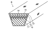
図1は、実施形態に係るラップドVベルトB(伝動ベルト)を示す。実施形態に係るラップドVベルトBは、例えば、送風機やコンプレッサーに使用されるエンドレスのものである。実施形態に係るラップドVベルトBは、例えば、ベルト長さが500〜2500mm、ベルト幅が10.0〜23.0mm、及びベルト厚さが5.5〜14.0mmである。 FIG. 1 shows a wrapped V-belt B (power transmission belt) according to the embodiment. The wrapped V-belt B according to the embodiment is, for example, an endless one used for a blower or a compressor. The wrapped V-belt B according to the embodiment has, for example, a belt length of 500 to 2500 mm, a belt width of 10.0 to 23.0 mm, and a belt thickness of 5.5 to 14.0 mm.
実施形態に係るラップドVベルトBは、ベルト内周側の圧縮ゴム層11と、中間の接着ゴム層12と、ベルト外周側の伸張ゴム層13との三重の層に構成された横断面形状が台形のゴム製のベルト本体10を備えている。ベルト本体10の厚さ方向の中間部、より具体的には、接着ゴム層12の厚さ方向の中間部には、層を形成するように織布心体14が埋設されている。ベルト本体10は、全体が外被補強布15によって覆われている。
The wrapped V-belt B according to the embodiment has a cross-sectional shape configured as a triple layer of a
圧縮ゴム層11、接着ゴム層12、及び伸張ゴム層13は、ゴム成分に各種のゴム配合剤が配合されて混練された未架橋ゴム組成物が加熱及び加圧されて架橋剤により架橋したゴム組成物で形成されている。
The
ゴム成分としては、例えば、天然ゴム(NR)、EPDMやEPMのエチレン−α−オレフィンエラストマー、クロロプレンゴム(CR)、水素化ニトリルゴム(H−NBR)、イソプレンゴム(IR)、スチレンブタジエンゴム(SBR)、ブタジエンゴム(BR)、アクリロニトリルブタジエンゴム(NBR)、ブチルゴム(IIR)等が挙げられる。ゴム成分は、これらのうちの1種又は2種以上のブレンドゴムであることが好ましい。 Examples of rubber components include natural rubber (NR), EPDM and EPM ethylene-α-olefin elastomers, chloroprene rubber (CR), hydrogenated nitrile rubber (H-NBR), isoprene rubber (IR), styrene butadiene rubber ( SBR), butadiene rubber (BR), acrylonitrile butadiene rubber (NBR), butyl rubber (IIR) and the like. The rubber component is preferably a blend rubber of one or more of these.
ゴム配合剤としては、カーボンブラックなどの補強材、充填剤、軟化剤、加工助剤、加硫促進助剤、老化防止剤、架橋剤、加硫促進剤等が挙げられる。 Examples of rubber compounding agents include reinforcing materials such as carbon black, fillers, softeners, processing aids, vulcanization acceleration aids, anti-aging agents, crosslinking agents, and vulcanization accelerators.
図2は織布心体14を示す。
FIG. 2 shows the
織布心体14は、経糸14a及び緯糸14bにより構成された織布である。織布心体14の織物組織としては、例えば、平織、斜文織、朱子織、及びそれらの変化織等が挙げられる。これらのうち平織が好ましい。
The
経糸14a及び緯糸14bを形成する繊維材料としては、綿、麻等の天然繊維;6,6−ナイロン、4,6−ナイロン又は6−ナイロンなどのナイロン繊維(脂肪族ポリアミド繊維)、ポリエステル繊維、アラミド繊維(芳香族ポリアミド繊維)、PBO繊維等の合成繊維等が挙げられる。経糸14a及び緯糸14bは、天然繊維の紡績糸であっても、合成繊維の紡績糸又はフィラメント糸であっても、天然繊維及び合成繊維の混紡糸であっても、いずれでもよい。より具体的な織布心体14としては、例えば、経糸14a及び緯糸14bを綿の紡績糸で構成した織布、綿及びポリエステル繊維の混紡糸で構成した織布、綿及びアラミド繊維の混紡糸で構成した織布、アラミド繊維のフィラメント糸で構成した織布等が挙げられる。経糸14a及び緯糸14bの糸構成は、片撚り糸であっても、諸撚り糸であっても、ラング撚り糸であっても、いずれでもよい。経糸14a及び緯糸14bの繊度は、例えば100〜1200dtexである。経糸14a及び緯糸14bの糸密度は、例えば30〜85本/5cmである。経糸14a及び緯糸14bは、繊維材料、糸構成、繊度、及び糸密度が同一であることが好ましいが、それらが異なっていてもよい。
Examples of the fiber material forming the
織布心体14を構成する経糸14a及び緯糸14bのなす角は90°ではなく、それらのなす狭角θは20〜35°である。そして、織布心体14は、その狭角θがベルト長さ方向を向いて開口するように設けられている。このように実施形態に係るラップドVベルトによれば、ベルト本体に埋設された織布心体を構成する経糸14a及び緯糸14bのなす狭角θが20〜35°であると共に、その狭角θがベルト長さ方向を向いて開口していることにより、ベルト特性として引張初期が低弾性率となることから、軸間距離が固定されたプーリレイアウトに容易に組み付けることができる一方、ベルト走行時に更に伸ばされた際には高弾性率となり、優れた動力伝達能力を得ることができる。
The angle formed by the
経糸14a及び緯糸14bのなす狭角θは、かかる観点から、好ましくは15°以上、より好ましくは20°以上であり、また、好ましくは40°以下、より好ましくは35°以下である。また、経糸14aがベルト長さ方向に対してなす狭角及び緯糸14bがベルト長さ方向に対してなす狭角は同一であることが好ましい。
From this viewpoint, the narrow angle θ formed by the
織布心体14には、ベルト本体10に対する接着性を付与するため、成形加工前に接着処理が施されている。かかる接着処理としては、エポキシ樹脂やイソシアネート樹脂を含む下地接着処理液に浸漬して加熱する下地接着処理、いわゆるRFL水溶液に浸漬して加熱するRFL接着処理、ゴム糊に浸漬して乾燥させるソーキングゴム糊接着処理、ベルト本体10側となる面にゴム糊をコーティングして乾燥させるコーティングゴム糊接着処理が挙げられる。織布心体14に施される接着処理は、これらのうち1種又は2種以上であることが好ましい。
The
外被補強布15は、例えば、綿、ポリアミド繊維、ポリエステル繊維、アラミド繊維等の糸で形成された織布、編物、不織布等によって構成されている。
The
外被補強布15には、ベルト本体10に対する接着性を付与するため、成形加工前に接着処理が施されている。かかる接着処理としては、エポキシ樹脂やイソシアネート樹脂を含む下地接着処理液に浸漬して加熱する下地接着処理、いわゆるRFL水溶液に浸漬して加熱するRFL接着処理、ゴム糊に浸漬して乾燥させるソーキングゴム糊接着処理、ベルト本体10側となる面にゴム糊をコーティングして乾燥させるコーティングゴム糊接着処理が挙げられる。外被補強布15に施される接着処理は、これらのうち1種又は2種以上であることが好ましい。なお、外被補強布15には、防かび剤等を含むゴム組成物を擦り込むフリクション処理が施されていてもよい。
In order to impart adhesion to the belt
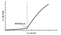
実施形態に係るラップドVベルトBは、上記の通り、引張初期が低弾性率であるものの、図3に示すように、ベルト伸び率が2〜4%の範囲において、弾性率が急激に高くなる弾性率変化点を有することが好ましい。この弾性率変化点は、ベルト伸び率が2.5〜3.5%の範囲にあることがより好ましい。 As described above, the wrapped V-belt B according to the embodiment has a low elastic modulus at the initial stage of tension. However, as shown in FIG. 3, the elastic modulus rapidly increases in the range of 2 to 4% as shown in FIG. It is preferable to have an elastic modulus change point. The elastic modulus change point is more preferably in the range of the belt elongation of 2.5 to 3.5%.
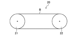
図4は、実施形態に係るラップドVベルトBを用いたベルト伝動装置20を示す。
FIG. 4 shows a
このベルト伝動装置20は、各々、外周にV溝が形成された駆動プーリ21及び従動プーリ22を備えている。これらの駆動プーリ21及び従動プーリ22は、それぞれ固定軸に取り付けられているため、軸間距離が固定されたプーリレイアウトを構成している。このような軸間距離が固定されたプーリレイアウトのベルト伝動装置20における実施形態に係るラップドVベルトBの組み付け時には、実施形態に係るラップドVベルトBは、ベルト特性として引張初期が低弾性率であることから、引っ張って伸ばすことにより容易に組み付けることができる。そして、組み付けられたラップドVベルトBは、ベルト伸び率が弾性率変化点よりも低いやや伸びた状態で、駆動プーリ21及び従動プーリ22に巻き掛けられることとなるが、ベルト走行時には、張り側部分では更に伸ばされて高弾性率となり、その結果、優れた動力伝達能力を得ることができる。
The
次に、実施形態に係るラップドVベルトBの製造方法を説明する。 Next, the manufacturing method of the wrapped V belt B which concerns on embodiment is demonstrated.
まず、圧縮ゴム層用のゴムシート11’、接着ゴム層用のゴムシート12’、及び伸張ゴム層用のゴムシート13’、並びに経糸14a及び緯糸14bのなす狭角θが20〜35°である織布心体14’及び外被補強布15’を準備する。なお、織布心体14’及び外被補強布15’には所定の接着処理を施す。
First, the narrow angle θ formed by the
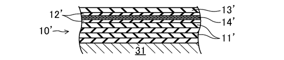
次いで、図5Aに示すように、マントル31に、圧縮ゴム層用のゴムシート11’を複数回巻き付け、その上に、接着ゴム層用のゴムシート12’を巻き付ける。その上に、図5Bに示すように、織布心体14’を巻き付ける。この織布心体14’の巻き付け回数は2〜3回である。また、織布心体14’は、経糸14a及び緯糸14bのなす狭角θがベルト長さ方向を向いて開口するように設ける。更にその上に、図5Cに示すように、接着ゴム層用のゴムシート12’及び伸張ゴム層用のゴムシート13’を順に巻き付けて円筒状の積層構造体10’を作製する。
Next, as shown in FIG. 5A, the rubber sheet 11 'for the compression rubber layer is wound around the mantle 31 a plurality of times, and the rubber sheet 12' for the adhesive rubber layer is wound thereon. On top of that, as shown in FIG. 5B, a woven fabric core 14 'is wound. The number of windings of the woven fabric core 14 'is 2 to 3 times. Further, the woven fabric core 14 'is provided so that the narrow angle θ formed by the
次いで、図5Dに示すように、円筒状の積層構造体10’をマントル31上で所定幅に輪切りにした後、それらをマントル31から取り外す。
Next, as shown in FIG. 5D, the cylindrical
次いで、環状の積層構造体10’を、圧縮ゴム層用のゴムシート11’側を外側にして一対のプーリ間に巻き掛けて回転させながら、図5Eに示すように、圧縮ゴム層用のゴムシート11’の積層部分の両側をV型に斜めに切除して体積を調整する。
Next, as shown in FIG. 5E, the annular
続いて、図5Fに示すように、環状の積層構造体10’の外周を外被補強布15’で被覆する。
Subsequently, as shown in FIG. 5F, the outer periphery of the annular
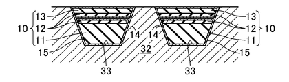
そして、図5Gに示すように、ラッピングした環状の積層構造体10’を円筒金型32の溝33に嵌め入れ、それを加硫缶に入れて加熱及び加圧する。このとき、環状の積層構造体10’のゴム成分が架橋してベルト本体10を形成し、且つ織布心体14’及び外被補強布15’がベルト本体10に接着一体化して実施形態に係るラップドVベルトBが製造される。
Then, as shown in FIG. 5G, the wrapping annular
なお、以上の実施形態では、ラップドVベルトBを示したが、特にこれに限定されるものではなく、ローエッジVベルト、Vリブドベルト、平ベルト、歯付ベルト等であってもよい。 In the above embodiment, the wrapped V-belt B is shown. However, the present invention is not particularly limited thereto, and may be a low-edge V-belt, a V-ribbed belt, a flat belt, a toothed belt, or the like.
本発明は伝動ベルトの技術分野において有用である。 The present invention is useful in the technical field of power transmission belts.
B ラップドVベルト(伝動ベルト)
10 ベルト本体
14 織布心体
14a 経糸
14b 緯糸
B Wrapped V belt (power transmission belt)
10
Claims (2)
前記織布心体を構成する経糸及び緯糸のなす狭角が20〜35°であると共に、前記狭角がベルト長さ方向を向いて開口した伝動ベルト。 A transmission belt comprising a rubber belt main body and a woven fabric core embedded so as to form a layer in an intermediate portion in the thickness direction of the belt main body,
A transmission belt in which a narrow angle formed by warps and wefts constituting the woven fabric core is 20 to 35 °, and the narrow angle is open in a belt length direction.
前記経糸がベルト長さ方向に対してなす狭角及び前記緯糸がベルト長さ方向に対してなす狭角が同一である伝動ベルト。 The power transmission belt according to claim 1,
A transmission belt in which the narrow angle formed by the warp with respect to the belt length direction and the narrow angle formed by the weft with respect to the belt length direction are the same.
Priority Applications (1)
| Application Number | Priority Date | Filing Date | Title |
|---|---|---|---|
| JP2016053979A JP2017166633A (en) | 2016-03-17 | 2016-03-17 | Transmission belt |
Applications Claiming Priority (1)
| Application Number | Priority Date | Filing Date | Title |
|---|---|---|---|
| JP2016053979A JP2017166633A (en) | 2016-03-17 | 2016-03-17 | Transmission belt |
Publications (1)
| Publication Number | Publication Date |
|---|---|
| JP2017166633A true JP2017166633A (en) | 2017-09-21 |
Family
ID=59909966
Family Applications (1)
| Application Number | Title | Priority Date | Filing Date |
|---|---|---|---|
| JP2016053979A Pending JP2017166633A (en) | 2016-03-17 | 2016-03-17 | Transmission belt |
Country Status (1)
| Country | Link |
|---|---|
| JP (1) | JP2017166633A (en) |
-
2016
- 2016-03-17 JP JP2016053979A patent/JP2017166633A/en active Pending
Similar Documents
| Publication | Publication Date | Title |
|---|---|---|
| KR101735084B1 (en) | Power transmission belt and belt transmission system including the power transmission belt | |
| US11828349B2 (en) | Banded friction power transmission belt | |
| KR102151822B1 (en) | Electric belt | |
| CN103511555A (en) | Cover fabric for power transmission belt and toothed belt | |
| JPWO2007142318A1 (en) | Toothed belt canvas and toothed belt including the same | |
| JP2016164455A (en) | Transmission belt, manufacturing method of transmission belt, reinforcing fabric and manufacturing method of reinforcing fabric | |
| JPH07228725A (en) | Rubber composition and power transmission belt using the same | |
| CN107532682B (en) | Wrapping cloth V belt and manufacturing method thereof | |
| JP6334595B2 (en) | Wrapped V-belt and method for manufacturing wrapped V-belt | |
| JP5730645B2 (en) | Aramid core wire and power transmission belt | |
| JP7487137B2 (en) | V-ribbed belt | |
| JP2017166633A (en) | Transmission belt | |
| WO2019193881A1 (en) | Friction transmission belt | |
| US10975933B2 (en) | Transmission belt and method for producing same | |
| TWI225536B (en) | Belt | |
| JP7430849B1 (en) | toothed belt | |
| JP6530877B1 (en) | Friction transmission belt | |
| WO2024009663A1 (en) | V-ribbed belt and method for manufacturing same | |
| JP2010255739A (en) | Transmission belt | |
| JP6603350B2 (en) | Low edge V belt | |
| WO2016136975A1 (en) | Transmission belt, method for manufacturing transmission belt, reinforcing fabric, and method for manufacturing reinforcing fabric | |
| JP5669814B2 (en) | Transmission belt |