JP2017166399A - Engine driven work machine - Google Patents
Engine driven work machine Download PDFInfo
- Publication number
- JP2017166399A JP2017166399A JP2016051821A JP2016051821A JP2017166399A JP 2017166399 A JP2017166399 A JP 2017166399A JP 2016051821 A JP2016051821 A JP 2016051821A JP 2016051821 A JP2016051821 A JP 2016051821A JP 2017166399 A JP2017166399 A JP 2017166399A
- Authority
- JP
- Japan
- Prior art keywords
- engine
- muffler
- exhaust
- cover
- tail pipe
- Prior art date
- Legal status (The legal status is an assumption and is not a legal conclusion. Google has not performed a legal analysis and makes no representation as to the accuracy of the status listed.)
- Granted
Links
Images
Classifications
-
- F—MECHANICAL ENGINEERING; LIGHTING; HEATING; WEAPONS; BLASTING
- F02—COMBUSTION ENGINES; HOT-GAS OR COMBUSTION-PRODUCT ENGINE PLANTS
- F02B—INTERNAL-COMBUSTION PISTON ENGINES; COMBUSTION ENGINES IN GENERAL
- F02B77/00—Component parts, details or accessories, not otherwise provided for
- F02B77/11—Thermal or acoustic insulation
- F02B77/13—Acoustic insulation
-
- H—ELECTRICITY
- H02—GENERATION; CONVERSION OR DISTRIBUTION OF ELECTRIC POWER
- H02K—DYNAMO-ELECTRIC MACHINES
- H02K5/00—Casings; Enclosures; Supports
- H02K5/24—Casings; Enclosures; Supports specially adapted for suppression or reduction of noise or vibrations
-
- F—MECHANICAL ENGINEERING; LIGHTING; HEATING; WEAPONS; BLASTING
- F01—MACHINES OR ENGINES IN GENERAL; ENGINE PLANTS IN GENERAL; STEAM ENGINES
- F01N—GAS-FLOW SILENCERS OR EXHAUST APPARATUS FOR MACHINES OR ENGINES IN GENERAL; GAS-FLOW SILENCERS OR EXHAUST APPARATUS FOR INTERNAL-COMBUSTION ENGINES
- F01N1/00—Silencing apparatus characterised by method of silencing
- F01N1/24—Silencing apparatus characterised by method of silencing by using sound-absorbing materials
-
- F—MECHANICAL ENGINEERING; LIGHTING; HEATING; WEAPONS; BLASTING
- F01—MACHINES OR ENGINES IN GENERAL; ENGINE PLANTS IN GENERAL; STEAM ENGINES
- F01N—GAS-FLOW SILENCERS OR EXHAUST APPARATUS FOR MACHINES OR ENGINES IN GENERAL; GAS-FLOW SILENCERS OR EXHAUST APPARATUS FOR INTERNAL-COMBUSTION ENGINES
- F01N13/00—Exhaust or silencing apparatus characterised by constructional features
- F01N13/002—Apparatus adapted for particular uses, e.g. for portable devices driven by machines or engines
-
- F—MECHANICAL ENGINEERING; LIGHTING; HEATING; WEAPONS; BLASTING
- F01—MACHINES OR ENGINES IN GENERAL; ENGINE PLANTS IN GENERAL; STEAM ENGINES
- F01N—GAS-FLOW SILENCERS OR EXHAUST APPARATUS FOR MACHINES OR ENGINES IN GENERAL; GAS-FLOW SILENCERS OR EXHAUST APPARATUS FOR INTERNAL-COMBUSTION ENGINES
- F01N13/00—Exhaust or silencing apparatus characterised by constructional features
- F01N13/007—Apparatus used as intake or exhaust silencer
-
- F—MECHANICAL ENGINEERING; LIGHTING; HEATING; WEAPONS; BLASTING
- F01—MACHINES OR ENGINES IN GENERAL; ENGINE PLANTS IN GENERAL; STEAM ENGINES
- F01N—GAS-FLOW SILENCERS OR EXHAUST APPARATUS FOR MACHINES OR ENGINES IN GENERAL; GAS-FLOW SILENCERS OR EXHAUST APPARATUS FOR INTERNAL-COMBUSTION ENGINES
- F01N13/00—Exhaust or silencing apparatus characterised by constructional features
- F01N13/14—Exhaust or silencing apparatus characterised by constructional features having thermal insulation
-
- F—MECHANICAL ENGINEERING; LIGHTING; HEATING; WEAPONS; BLASTING
- F01—MACHINES OR ENGINES IN GENERAL; ENGINE PLANTS IN GENERAL; STEAM ENGINES
- F01P—COOLING OF MACHINES OR ENGINES IN GENERAL; COOLING OF INTERNAL-COMBUSTION ENGINES
- F01P1/00—Air cooling
- F01P1/06—Arrangements for cooling other engine or machine parts
-
- F—MECHANICAL ENGINEERING; LIGHTING; HEATING; WEAPONS; BLASTING
- F01—MACHINES OR ENGINES IN GENERAL; ENGINE PLANTS IN GENERAL; STEAM ENGINES
- F01P—COOLING OF MACHINES OR ENGINES IN GENERAL; COOLING OF INTERNAL-COMBUSTION ENGINES
- F01P5/00—Pumping cooling-air or liquid coolants
- F01P5/02—Pumping cooling-air; Arrangements of cooling-air pumps, e.g. fans or blowers
- F01P5/06—Guiding or ducting air to, or from, ducted fans
-
- F—MECHANICAL ENGINEERING; LIGHTING; HEATING; WEAPONS; BLASTING
- F16—ENGINEERING ELEMENTS AND UNITS; GENERAL MEASURES FOR PRODUCING AND MAINTAINING EFFECTIVE FUNCTIONING OF MACHINES OR INSTALLATIONS; THERMAL INSULATION IN GENERAL
- F16M—FRAMES, CASINGS OR BEDS OF ENGINES, MACHINES OR APPARATUS, NOT SPECIFIC TO ENGINES, MACHINES OR APPARATUS PROVIDED FOR ELSEWHERE; STANDS; SUPPORTS
- F16M1/00—Frames or casings of engines, machines or apparatus; Frames serving as machinery beds
-
- H—ELECTRICITY
- H02—GENERATION; CONVERSION OR DISTRIBUTION OF ELECTRIC POWER
- H02K—DYNAMO-ELECTRIC MACHINES
- H02K7/00—Arrangements for handling mechanical energy structurally associated with dynamo-electric machines, e.g. structural association with mechanical driving motors or auxiliary dynamo-electric machines
- H02K7/18—Structural association of electric generators with mechanical driving motors, e.g. with turbines
- H02K7/1807—Rotary generators
- H02K7/1815—Rotary generators structurally associated with reciprocating piston engines
-
- F—MECHANICAL ENGINEERING; LIGHTING; HEATING; WEAPONS; BLASTING
- F01—MACHINES OR ENGINES IN GENERAL; ENGINE PLANTS IN GENERAL; STEAM ENGINES
- F01N—GAS-FLOW SILENCERS OR EXHAUST APPARATUS FOR MACHINES OR ENGINES IN GENERAL; GAS-FLOW SILENCERS OR EXHAUST APPARATUS FOR INTERNAL-COMBUSTION ENGINES
- F01N2260/00—Exhaust treating devices having provisions not otherwise provided for
- F01N2260/02—Exhaust treating devices having provisions not otherwise provided for for cooling the device
- F01N2260/022—Exhaust treating devices having provisions not otherwise provided for for cooling the device using air
-
- F—MECHANICAL ENGINEERING; LIGHTING; HEATING; WEAPONS; BLASTING
- F01—MACHINES OR ENGINES IN GENERAL; ENGINE PLANTS IN GENERAL; STEAM ENGINES
- F01N—GAS-FLOW SILENCERS OR EXHAUST APPARATUS FOR MACHINES OR ENGINES IN GENERAL; GAS-FLOW SILENCERS OR EXHAUST APPARATUS FOR INTERNAL-COMBUSTION ENGINES
- F01N2590/00—Exhaust or silencing apparatus adapted to particular use, e.g. for military applications, airplanes, submarines
- F01N2590/06—Exhaust or silencing apparatus adapted to particular use, e.g. for military applications, airplanes, submarines for hand-held tools or portables devices
-
- F—MECHANICAL ENGINEERING; LIGHTING; HEATING; WEAPONS; BLASTING
- F02—COMBUSTION ENGINES; HOT-GAS OR COMBUSTION-PRODUCT ENGINE PLANTS
- F02B—INTERNAL-COMBUSTION PISTON ENGINES; COMBUSTION ENGINES IN GENERAL
- F02B63/00—Adaptations of engines for driving pumps, hand-held tools or electric generators; Portable combinations of engines with engine-driven devices
- F02B63/04—Adaptations of engines for driving pumps, hand-held tools or electric generators; Portable combinations of engines with engine-driven devices for electric generators
- F02B63/044—Adaptations of engines for driving pumps, hand-held tools or electric generators; Portable combinations of engines with engine-driven devices for electric generators the engine-generator unit being placed on a frame or in an housing
Landscapes
- Engineering & Computer Science (AREA)
- General Engineering & Computer Science (AREA)
- Mechanical Engineering (AREA)
- Chemical & Material Sciences (AREA)
- Combustion & Propulsion (AREA)
- Power Engineering (AREA)
- Physics & Mathematics (AREA)
- Acoustics & Sound (AREA)
- Exhaust Silencers (AREA)
Abstract
Description
本発明は、外装ケースの内部にエンジンおよびマフラーが収納されるエンジン駆動作業機に関する。 The present invention relates to an engine-driven work machine in which an engine and a muffler are housed inside an exterior case.
エンジン駆動作業機として、外装ケースの内部にマフラーが収納され、マフラーからテールパイプが消音室に延ばされ、テールパイプの排気口が排出口に対向するように横向きに開口される発電機が知られている。また、消音室には吸音材が設けられている。このエンジン駆動作業機によれば、テールパイプの排気口から消音室に排気ガスが導かれ、導かれた排気ガスが消音室を経て排出口から外装ケースの外部に排出される(例えば、特許文献1参照。)。 As an engine-driven work machine, there is known a generator in which a muffler is housed inside an exterior case, a tail pipe is extended from the muffler to a silencer chamber, and the tail pipe exhaust port is opened sideways so as to face the discharge port. It has been. Further, a sound absorbing material is provided in the sound deadening chamber. According to this engine-driven work machine, exhaust gas is guided from the tail pipe exhaust port to the silencer chamber, and the exhaust gas thus guided is exhausted from the exhaust port to the outside of the exterior case through the silencer chamber (for example, Patent Documents). 1).
特許文献1のエンジン駆動作業機によれば、テールパイプの排気口から消音室に排気ガスを導くことにより、排気ガスの排気音を消音室である程度遮音することが可能である。さらに、消音室には吸音材が設けられることにより、排気ガスの排気音を吸音材である程度吸音することが可能である。 According to the engine-driven working machine of Patent Document 1, it is possible to block the exhaust sound of the exhaust gas to some extent in the silencer chamber by introducing the exhaust gas from the exhaust port of the tail pipe to the silencer chamber. Furthermore, the sound absorbing chamber is provided with a sound absorbing material, so that the exhaust sound of the exhaust gas can be absorbed to some extent by the sound absorbing material.
しかし、特許文献1のエンジン駆動作業機は、テールパイプの排気口が排出口に対向するように横向きに開口される。よって、排気ガスの排気音を消音室で良好に遮音することが難しい。このため、排気音(すなわち、騒音)を低減する工夫が要求され、この観点から改良の余地が残されている。 However, the engine-driven working machine of Patent Document 1 is opened sideways so that the exhaust port of the tail pipe faces the exhaust port. Therefore, it is difficult to properly isolate the exhaust sound of the exhaust gas in the silencer chamber. For this reason, a device for reducing exhaust noise (that is, noise) is required, and there is room for improvement from this viewpoint.
本発明は、排気音(すなわち、騒音)を良好に低減できるエンジン駆動作業機を提供することを課題とする。 An object of the present invention is to provide an engine-driven work machine that can satisfactorily reduce exhaust noise (that is, noise).
請求項1に係る発明は、外装ケースの内部にエンジンおよびマフラーが収納されるエンジン駆動作業機において、前記マフラーの下部に設けられるテールパイプと、該テールパイプの上方に配置され、前記外装ケースに形成された排出口と、該排出口に対向するように配置され、冷却ファンから送風される冷却風を前記マフラーの下方へ導く導風板と、を備える、エンジン駆動作業機が提供される。 The invention according to claim 1 is an engine-driven work machine in which an engine and a muffler are housed in an exterior case, a tail pipe provided at a lower portion of the muffler, and disposed above the tail pipe, An engine-driven work machine is provided that includes the formed discharge port and an air guide plate that is disposed so as to face the discharge port and guides the cooling air blown from the cooling fan to the lower side of the muffler.
このように、マフラーの下部にテールパイプを設け、テールパイプの上方に排出口を配置した。よって、テールパイプの排気口を排出口から下方に離すことができる。この排気口から排気ガスが排出される。これにより、排気ガスを排出口から離れた位置に排出できるので、排気音の遮音を高め、排気音(すなわち、騒音)を良好に低減できる。 Thus, a tail pipe was provided at the lower part of the muffler, and a discharge port was disposed above the tail pipe. Therefore, the exhaust port of the tail pipe can be separated downward from the discharge port. Exhaust gas is discharged from this exhaust port. Thereby, since exhaust gas can be discharged | emitted to the position away from the discharge port, the sound insulation of exhaust sound can be improved and exhaust sound (namely, noise) can be reduced favorably.
また、排出口に対向するように導風板を配置し、導風板で冷却風をマフラーの下方へ導くようにした。よって、テールパイプや、テールパイプの周囲に冷却風を導くことができる。これにより、テールパイプの周囲の部材が排気熱により劣化することを防止できる。 In addition, an air guide plate is arranged so as to face the discharge port, and the cooling air is guided to the lower side of the muffler by the air guide plate. Therefore, the cooling air can be guided to the tail pipe or around the tail pipe. Thereby, it can prevent that the member around a tail pipe deteriorates by exhaust heat.
請求項2に係る発明では、好ましくは、前記エンジン駆動作業機は、さらに、前記マフラーおよび前記テールパイプを覆うプロテクタと、該プロテクタの内面に設けられる吸音材と、を備える。 In the invention according to claim 2, preferably, the engine-driven work machine further includes a protector that covers the muffler and the tail pipe, and a sound absorbing material provided on an inner surface of the protector.
このように、マフラーおよびテールパイプをプロテクタで覆い、プロテクタの内面に吸音材を設けた。これにより、排出口から排出される排気音を吸音材で吸音でき、排気音を一層良好に低減できる。
また、冷却風を導風板でテールパイプや、テールパイプの周囲に冷却風を導くことにより、プロテクタおよび吸音材に冷却風を導くことができる。これにより、プロテクタおよび吸音材が排気熱により劣化することを防止できる。
Thus, the muffler and the tail pipe were covered with the protector, and the sound absorbing material was provided on the inner surface of the protector. Thereby, the exhaust sound discharged from the discharge port can be absorbed by the sound absorbing material, and the exhaust sound can be further reduced.
Further, the cooling air can be guided to the protector and the sound absorbing material by guiding the cooling air to the tail pipe or the periphery of the tail pipe with the air guide plate. Thereby, it can prevent that a protector and a sound-absorbing material deteriorate by exhaust heat.
請求項3に係る発明では、好ましくは、前記テールパイプは、該テールパイプの排気口が前記排出口の開口方向に対して交差するように開口される。 In the invention which concerns on Claim 3, Preferably, the said tail pipe is opened so that the exhaust port of this tail pipe may cross | intersect with the opening direction of the said discharge port.
このように、テールパイプの排気口を排出口の開口方向に対して交差するように開口させた。よって、排気音の進行方向から排出口の向きをずらすことができる。これにより、排気音の遮音を高め、排気音を一層良好に低減できる。 In this way, the tail pipe exhaust port was opened so as to intersect the opening direction of the discharge port. Therefore, the direction of the discharge port can be shifted from the traveling direction of the exhaust sound. Thereby, the sound insulation of the exhaust sound can be increased, and the exhaust sound can be further reduced.
本発明によれば、マフラーの下部にテールパイプを設け、テールパイプの上方に排出口を配置した。これにより、排気音(すなわち、騒音)を良好に低減できることができる。 According to the present invention, the tail pipe is provided at the lower portion of the muffler, and the discharge port is disposed above the tail pipe. Thereby, exhaust sound (namely, noise) can be reduced favorably.
本発明を実施するための最良の形態を添付図に基づいて以下に説明する。
なお、図中に示す「前(Fr)」、「後(Rr)」、「左(L)」、「右(R)」はエンジン駆動作業機10の操作盤27側を前(Fr)とする。
ここで、本発明に係るエンジン駆動作業機10を実施例において「発電機10」に適用する例について説明するが、エンジン駆動作業機10を草刈機、除雪機、耕耘機などの他の作業機に適用することも可能である。
The best mode for carrying out the present invention will be described below with reference to the accompanying drawings.
In addition, “front (Fr)”, “rear (Rr)”, “left (L)”, and “right (R)” shown in the figure are the front (Fr) on the
Here, an example in which the engine-driven
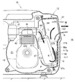
実施例に係るエンジン駆動作業機(具体的には、発電機)10について説明する。
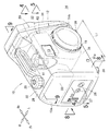
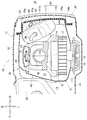
図1、図2に示すように、発電機10は、発電機10の外枠を形成する外装ケース12と、外装ケース12の内部13に収納されるエンジン15(図3参照)と、エンジン15の左側に設けられる発電部(作業部)16と、発電部16の左側に設けられる冷却ファン17と、冷却ファン17の左側に設けられるリコイルスタータ18と、エンジン15を覆うカバーユニット20とを備える。
リコイルスタータ18がリコイルカバー19で覆われる。
An engine-driven work machine (specifically, a generator) 10 according to an embodiment will be described.
As shown in FIGS. 1 and 2, the
The
また、発電機10は、エンジン15に連通する吸気系(吸気系部品)22と、エンジン15に連結する排気系(排気系部品)24(図4参照)と、エンジン15の前方に配置される燃料タンク26と、外装ケース12の前壁12aに設けられる操作盤27とを備える。
The
発電機10によれば、リコイルスタータ18を手動で回転することにより、エンジン15(図3参照)が駆動する。エンジン15が駆動することによりクランクシャフト41(図5参照)が回転する。クランクシャフト41に発電部16のロータが連結される。よって、クランクシャフト41が回転することにより発電部16のロータが回転する。
According to the
発電部16のロータが回転することにより、ロータとステータとに起電力が発生し、発電部16で発電がおこなわれる。発電部16で発電された直流電力がインバータで交流電力に変換され、操作盤27のコネクタ28から外部に給電される。
When the rotor of the
また、発電部16のロータに冷却ファン17が連結される。よって、発電部16のロータが回転することにより、冷却ファン17が回転する。冷却ファン17が回転することにより、外装ケース12の外部14から内部13に外気を吸い込み、吸い込んだ外気を冷却風として吸気系22、エンジン15や排気系24に送風する。
A
ここで、発電機10(すなわち、エンジン15)が駆動することにより、クランクシャフト41(図5参照)の周りに振動が発生する。クランクシャフト41の周りに発生する振動は発電機10で抑えられる。
なお、クランクシャフト41の周りに発生する振動を抑える手段については後で詳しく説明する。
Here, the generator 10 (that is, the engine 15) is driven to generate vibration around the crankshaft 41 (see FIG. 5). Vibration generated around the
A means for suppressing vibration generated around the
外装ケース12は、外装ケース12の左半部を形成する左ケース31と、外装ケース12の右半部を形成する右ケース32と、左ケース31および右ケース32の前端部に取り付けられる前ケース33と、左ケース31および右ケース32の後端部に取り付けられる後ケース34と、各ケース31〜34を支持するアンダカバー35(図3参照)とを備える。
後ケース34は、後壁34aの上部に略矩形状の排出口37(図9参照)を有する。すなわち、後壁34aの上部が排出口37で略矩形状に開口される。
The
The
左ケース31、右ケース32、前ケース33、後ケース34およびアンダカバー35で外装ケース12が前後方向(一方向)へ延びるように平面視略矩形状に形成される。具体的には、外装ケース12が前後方向へ延びる略矩形枠体状に形成される。
外装ケース12の前後方向に対して交差(具体的には、直交)するようにクランクシャフト41(図5参照)が配置される。
The
The crankshaft 41 (see FIG. 5) is disposed so as to intersect (specifically, orthogonally) with the front-rear direction of the
外装ケース12の内部13にエンジン15(図3参照)、カバーユニット20、燃料タンク26が収納される。この状態において、燃料タンク26のタンクキャップ29が外装ケース12の上方へ突出(露出)される。
また、外装ケース12の前壁12aが前ケース33の前壁で形成される。この前ケース33の前壁12aに操作盤27が設けられる。
An engine 15 (see FIG. 3), a
Further, the
アンダカバー35の前端部の左右側に前ラバー支持部38(左側の前ラバー支持部38のみを図示する)が取り付けられる。また、アンダカバー35の後端部の左右側に後ラバー支持部39(左側の後ラバー支持部39のみを図示する)が取り付けられる。左右側の前ラバー支持部38および左右側の後ラバー支持部39で発電機10が床面などに支持される。
A front rubber support portion 38 (only the left front
ここで、外装ケース12が前後方向へ延びるように平面視略矩形状に形成されている。よって、アンダカバー35の前端部と後端部との間が大きく確保される。
これにより、アンダカバー35の前端部に取り付けられる前ラバー支持部38と、アンダカバー35の後端部に取り付けられる後ラバー支持部39と間の間隔L1が大きく確保される。
Here, the
Thereby, the space | interval L1 between the front
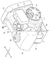
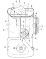
図3、図4に示すように、エンジン15がカバーユニット20の内部21に収納される。また、カバーユニット20が外装ケース12の内部13に収納される。
エンジン15は、外装ケース12の左右方向へ延びるクランクシャフト41(図5参照)と、クランクシャフト41の上方に配置されるシリンダ42と、シリンダ42の上端部に設けられるシリンダヘッド43と、シリンダヘッド43に設けられる吸気ポート44および排気ポート45と、クランクシャフト41に連結される動弁機構46とを備える。
As shown in FIGS. 3 and 4, the
The
図5に示すように、クランクシャフト41は、外装ケース12の前後方向に対して交差(具体的には、直交)するように配置される。換言すれば、外装ケース12の左右方向へ延びるようにクランクシャフト41が配置される。
すなわち、外装ケース12の内部13にエンジン15が収納された状態において、エンジン15が外装ケース12に対して横向きに配置される。
As shown in FIG. 5, the
That is, the
図4、図5に示すように、動弁機構46は、クランクシャフト41に同軸上に設けられる駆動タイミングプーリ51と、駆動タイミングプーリ51の上方に設けられる従動タイミングプーリ52と、駆動タイミングプーリ51および従動タイミングプーリ52に掛け渡されるカム駆動ベルト53とを備える。
駆動タイミングプーリ51、従動タイミングプーリ52およびカム駆動ベルト53がカムケース54の内部に収納される。カムケース54はシリンダ42と一体に形成される。
As shown in FIGS. 4 and 5, the
The
また、動弁機構46は、従動タイミングプーリ52を支持するカムシャフト56と、カムシャフト56のカムで駆動する吸気バルブ57および排気バルブ58とを備える。すなわち、動弁機構46は、オーバヘッドカムシャフト(OHC)型の機構である。
カムシャフト56の一方側(すなわち、カムシャフト56に交差する方向の一方側)に吸気バルブ57が配置される。また、カムシャフト56の他方側(すなわち、カムシャフト56に交差する方向の他方側)に排気バルブ58が配置される。
The
An
さらに、動弁機構46のカムシャフト56がクランクシャフト41に対して平行に配置される。よって、カムシャフト56の前方側に吸気バルブ57が配置される。また、カムシャフト56の後方側に排気バルブ58が配置される。
これにより、吸気ポート44が外装ケース12の前後方向において、シリンダヘッド43(すなわち、エンジン15)の前側に配置される。また、排気ポート45が外装ケース12の前後方向において、シリンダヘッド43(すなわち、エンジン15)の後側に配置される。
Further, the
Thus, the
吸気ポート22に吸気系22の気化器61が直接連結される。気化器61は、吸気ポート44の前側(すなわち、エンジン15の前側)で、かつ、カバーユニット20の外側に配置される。具体的には、カバーユニット20にファンカバー81(後述する)が含まれ、ファンカバー81の外側に気化器61が配置される。
The
ここで、外装ケース12が前後方向に延びるように平面視略矩形状に形成されている。よって、吸気ポート44の前側に空間64を確保し易い。これにより、気化器61を配置する空間64を比較的容易に確保できる。
さらに、吸気ポート44側に気化器61が配置され、吸気ポート44に気化器61が直接連結される。これにより、気化器61から吸気ポート44へ流れる吸気の通気抵抗が小さく抑えられる。
Here, the
Further, the
また、気化器61には吸気系22のエアクリーナ62が連結される。エアクリーナ62は、エンジン15の左側で、かつ、冷却ファン17や発電部16の上方で、かつ、カバーユニット20の外側に配置される。
具体的には、カバーユニット20に含まれるファンカバー81の外側にエアクリーナ62が配置される。
The
Specifically, the
排気ポート45に排気系24の排気流路(排気マニホールド)66が連結される。排気流路66は、排気ポート45の後側(すなわち、エンジン15の後側)に配置される。また、排気流路66には排気系24のマフラー67が連結される。
マフラー67は、排気ポート45の後側(すなわち、エンジン15の後側)に配置され、かつ、カバーユニット20の内部21に収納される。マフラー67の下部67aにテールパイプ68が設けられる。テールパイプ68はマフラー67に連通される。
An exhaust passage (exhaust manifold) 66 of the
The
マフラー67の下部67aからテールパイプ68が上方へ向けて立ち上げられ、テールパイプ68の上端に排気口68aが上向きに開口される。マフラー67の下部67aからテールパイプ68に排気ガスが導かれ、導かれた配置ガスがテールパイプ68を経て排気口68aから排出される。
A
マフラー67の下部67aにテールパイプ68が設けられることにより、テールパイプ68の排気口68aが後ケース34の後壁34aの下部34b側に配置される。一方、後壁34aの上部に排出口37(図9参照)が開口される。
よって、テールパイプ68の排気口68aの上方に排出口37が配置される。
By providing the
Therefore, the
ここで、外装ケース12が前後方向に延びるように平面視略矩形状に形成されている。よって、排気ポートの後側に空間71を確保し易い。これにより、排気流路66やマフラー67を配置する空間71を比較的容易に確保できる。
さらに、排気ポート45側にマフラー67が配置される。よって、マフラー67を排気ポート45に連通する排気流路66を大きく湾曲させる必要がなく簡素化できる。これにより、排気流路66を流れる排気の通気抵抗が小さく抑えられる。
Here, the
Further, a
このように、外装ケース12の内部13にエンジン15が横向きに配置されることにより、気化器61を配置する空間64を容易に確保でき、かつ、排気流路66やマフラー67を配置する空間71を容易に確保できる。よって、空間64や空間71を確保するために外装ケース12を大形化する必要がない。
As described above, the
また、エンジン15が横向きに配置されることにより、吸気、排気の通気抵抗が小さく抑えられ、エンジン15の出力が確保される。よって、エンジン15の出力を確保するためにエンジン15を大形化する必要がない。
外装ケース12の大形化やエンジン15の大形化を抑えることにより、発電機10を持ち運びに適したスリムな構成とすることができる。
Further, by arranging the
By suppressing the increase in size of the
また、エンジン15の左側で、かつ、クランクシャフト41の延長線73側に発電部16が配置される。具体的には、クランクシャフト41と同軸上に発電部16が設けられる。
さらに、発電部16の左側で、かつ、クランクシャフト41の延長線73側に冷却ファン17が配置される。具体的には、クランクシャフト41と同軸上に冷却ファン17が設けられる。
Further, the
Further, the cooling
ここで、冷却ファン17から冷却風を吹き出す出口75が気化器61に対向するように配置される。すなわち、冷却風を吹き出す出口75がシリンダ42の左側で、かつ、シリンダ42の前側に配置される。換言すれば、冷却風を吹き出す出口75がシリンダ42の左前側に配置される。
Here, the
よって、冷却ファン17の出口75から送風された冷却風が、カバーユニット20で案内されてシリンダ42の左前側から発電部16に導かれる。発電部16に導かれた冷却風が、カバーユニット20で案内されて発電部16を経てシリンダ42の前側へ湾曲状に導かれる。これにより、冷却風で発電部16やシリンダ42を冷却できる。
また、シリンダ42の前側に導かれた冷却風が、カバーユニット20で案内されてシリンダ42を経てマフラー67へ導かれる。これにより、冷却ファン17の出口75から送風された冷却風で発電部16、シリンダ42およびマフラー67を効率よく冷却できる。
Therefore, the cooling air blown from the
The cooling air guided to the front side of the
図3、図6に示すように、エンジン15、気化器61およびマフラー67がカバーユニット20の内部21(図4参照)に収納される。
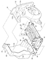
カバーユニット20は、エンジン15の左側に設けられるファンカバー81と、エンジン15の右側に設けられるシュラウド82と、ファンカバー81およびシュラウド82の各後端部に設けられるマフラーカバー83と、マフラーカバー83の前方に設けられる導風板84(図10も参照)とを備える。
As shown in FIGS. 3 and 6, the
The
ファンカバー81で冷却ファン17と発電部16とが覆われる。また、ファンカバー81の反対側(右側)にシュラウド82が設けられる。シュラウド82でエンジン15が右側から覆われる。
さらに、ファンカバー81の後端部とシュラウド82の後端部とにマフラーカバー83が設けられる。マフラーカバー83でマフラー67が覆われる。また、カバーユニット20の内部21で、かつ、マフラーカバー83の前方に導風板84が設けられる。
ファンカバー81、シュラウド82、マフラーカバー83、および導風板84については後で詳しく説明する。
The
Further, a
The
ファンカバー81およびシュラウド82が一体に連結された状態において、ファンカバー81およびシュラウド82は、第1取付手段85と、第2取付手段86とを含む。
第1取付手段85は、一体に連結されたファンカバー81およびシュラウド82の前下部に形成される。具体的には、第1取付手段85は、ファンカバー81の前下部に形成される第1カバー取付部87と、シュラウド82の前下部に形成される第1シュラウド取付部88とで構成される。
In a state where the
The first attachment means 85 is formed at the front lower portion of the
また、第2取付手段86は、一体に連結されたファンカバー81およびシュラウド82の後下部に形成される。具体的には、第2取付手段86は、ファンカバー81の後下部に形成される第2カバー取付部91と、シュラウド82の後下部に形成される第2シュラウド取付部92とで構成される。
The second attachment means 86 is formed at the lower rear portion of the
ファンカバー81およびシュラウド82の下方にアンダカバー35が配置される。このアンダカバー35にファンカバー81およびシュラウド82が支持される。
アンダカバー35は、平面視略矩形状に形成され、前端部35a側(外装ケースの一方向において一端側)に設けられる第1支持部94と、後端部35b側(外装ケースの一方向において他端側)に設けられる第2支持部95とを有する。
An under
The under
第1支持部94は、アンダカバー35の前左端部側に設けられる第1左支持部96と、アンダカバー35の前右端部側に設けられる第1右支持部97とを備える。
第2支持部95は、アンダカバー35の後左端部側に設けられる第2左支持部98と、アンダカバー35の後右端部側に設けられる第2右支持部99とを備える。
The
The
図7、図8に示すように、第1左支持部96と第1右支持部97との間に、第1カバー取付部87、第1シュラウド取付部88が介在される。この状態において、各取付部87,88が各支持部96,97にボルト102、ナット103で連結される。
また、ボルト102にスペーサ104が嵌合される。さらに、第1カバー取付部87とスペーサ104との間に左衝撃吸収部105が介在される。また、第1シュラウド取付部88とスペーサ104との間に右衝撃吸収部106が介在される。
As shown in FIGS. 7 and 8, a first
A
これにより、第1支持部94に第1取付手段85が取り付けられる。この状態において、第1支持部94に左ケース31の前取付部31aおよび右ケース32の前取付部32aがボルト102、ナット103で共締めされる。
同様に、第2支持部95に第2取付手段86が取り付けられる。この状態において、第1支持部94に左ケース31の後取付部31b(図1参照)および右ケース32の後取付部(図示せず)がボルト、ナットで共締めされる。
As a result, the first attachment means 85 is attached to the
Similarly, the second attachment means 86 is attached to the
これにより、アンダカバー35の左側に左ケース31が取り付けられ、アンダカバー35の右側に右ケース32が取り付けられる。
この状態において、ファンカバー81とシュラウド82とが一体に組み付けられる。さらに、外装ケース12の左ケース31および右ケース32が一体に組み付けられる。
As a result, the
In this state, the
このように、アンダカバー35に第1支持部94、第2支持部95が形成される。また、ファンカバー81およびシュラウド82に、第1取付手段85、第2取付手段86が形成される。さらに、第1取付手段85が第1支持部94に取り付けられ、第2取付手段が第2支持部に取り付けられる。
よって、ファンカバー81およびシュラウド82がアンダカバー35に取り付けられるために、取付部材を個別に用意する必要がない。これにより、発電機10の部品点数を一層減らすことができる。
As described above, the
Therefore, since the
つぎに、ファンカバー81とシュラウド82とについて説明する。
図4に示すように、外装ケース12の前後方向に交差させてクランクシャフト41が配置される。さらに、クランクシャフト41の延長線73上に冷却ファン17が設けられる。ここで、外装ケース12の前後方向において、エンジン15の後側にマフラー67が設けられる。
よって、冷却ファン17の軸線(すなわち、クランクシャフト41の延長線73)上からずれた位置にマフラー67が配置される。
Next, the
As shown in FIG. 4, the
Therefore, the
これにより、冷却ファン17側にファンカバー81を設け、ファンカバー81の反対側にシュラウド82を設けることが可能になる。したがって、ファンカバー81、シュラウド82の2部材で、エンジン15、発電部16、冷却ファン17を覆うことができ、部品点数を減らすことができる。
これにより、ファンカバー81とシュラウド82との組立工数を減らすことができ、コスト低減を図ることができる。
As a result, the
Thereby, the assembly man-hour of the
一方、通常の発電機は、ファンカバーとシュラウドとが別体で形成される。さらに、シュラウドが左シュラウドと右シュラウドとに分割される。このため、部品点数が増し、そのことがファンカバーとシュラウドとの組立工数を減らす妨げになっていた。 On the other hand, a normal generator has a fan cover and a shroud formed separately. Further, the shroud is divided into a left shroud and a right shroud. For this reason, the number of parts increased, which hindered the reduction of man-hours for assembling the fan cover and the shroud.
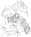
図7に示すように、ファンカバー81は、冷却ファン17および発電部16(図3参照)を覆う円筒状のカバー部111と、カバー部111の上部から後下部にかけて一体形成される左シュラウド部112と、カバー部111の前下部に形成される第1カバー取付部87と、カバー部111の後下部に形成される第2カバー取付部91とを有する。
As shown in FIG. 7, the
左シュラウド部112は、カバー部111の上部から上方へ立ち上げられる第1左壁112aと、第1左壁112aの上辺からシリンダヘッド43(図3参照)の上方へ張り出される左頂部112bと、左頂部112bの内辺から上方に立ち上げられる第2左壁112cと、第1左壁112a、左頂部112bおよび第2左壁112cの各後辺に一体に形成される左後シュラウド部112dとを有する。
The
左シュラウド部112がエンジン15の左側に配置される(図4参照)。ここで、左シュラウド部112とカバー部111とで凹部114が形成される。この凹部114にエアクリーナ62(図2参照)が配置される。
The
シュラウド82は、エンジン15(図3参照)の右側に配置される右側壁115と、右側壁115の下辺からアンダカバー35に沿って張り出される右底部116と、右側壁115の上辺からエンジン15側に張り出される右頂部117と、右側壁115からエンジン15側に張り出される前壁118と、右底部116の前部に形成される第1シュラウド取付部88と、右底部116の後部に形成される第2シュラウド取付部92とを有する。
シュラウド82でエンジン15が右側から覆われる。
The
The
図4、図5に示すように、ファンカバー81とシュラウド82とが一体に組み付けられる。この状態において、ファンカバー81とシュラウド82との後端部に後開口116が形成される。後開口116にマフラーカバー83が取り付けられる。
また、ファンカバー81、シュラウド82およびマフラーカバー83の内部21(すなわち、カバーユニット20の内部)に空間が形成される。内部21の空間に、エンジン15、発電部16、冷却ファン17およびマフラー67が収納される。
As shown in FIGS. 4 and 5, the
In addition, a space is formed in the inside 21 of the
この状態において、外装ケース12の前後方向に交差させてクランクシャフト41が配置される。すなわち、外装ケース12に対してエンジン15が横向きに配置される。この外装ケース12が前後方向に延びる平面視略矩形状に形成されている。
よって、前ラバー支持部38および後ラバー支持部39間の間隔L1が大きく確保される。
In this state, the
Therefore, the space | interval L1 between the front
ここで、発電機10(すなわち、エンジン15)が駆動することにより、クランクシャフト41の周りに振動が発生する。よって、外装ケース12に対してエンジン15が横向きに配置されることにより、クランクシャフト41の周りの振動を、外装ケース12の前後方向に作用させることができる。
これにより、エンジン駆動作業機10の振動を前ラバー支持部38および後ラバー支持部39で好適に抑えることができる。したがって、運転中における発電機10の振動を小さく抑えることができ、発電機10の商品性が高められる。
Here, vibration is generated around the
Thereby, the vibration of the engine
マフラー67は、排気ポート45に排気流路66を介して連通され、排気ポート45およびエンジン15の後側に配置される。この状態において、マフラー67が後開口116に配置される。
マフラー67やテールパイプ68がマフラーカバー83で覆われる。マフラーカバー83は、後開口116に取り付けられるプロテクタ117と、プロテクタ117の内面117aに取り付けられる吸音材118とを備える。
The
The
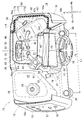
図9に示すように、プロテクタ117は、マフラー67および前記テールパイプ68を後方から覆うように形成される。プロテクタ117は、上部に形成される外形略矩形状のルーバ121を有する。ルーバ121は、後ケース34の排出口37の内側に位置し、かつ、排出口37に対向するように配置される。
さらに、プロテクタ117は、ファンカバー81の後端部81aとシュラウド82の後端部82bとに開口周縁部117bが一体に取り付けられる(図10も参照)。
As shown in FIG. 9, the
Further, the
また、テールパイプ68の排気口68aの上方に排出口37が配置される。すなわち、排出口37やルーバ121がテールパイプ68の排気口68aの上方に配置される。よって、テールパイプ68の排気口68aが排出口37から下方に離される。
これにより、排気口68aの排気ガスを排出口37やルーバ121から離れた位置に排気できる。
Further, the
Thereby, the exhaust gas of the
ここで、テールパイプ68の排気口68aが排出口37の開口方向(矢印A方向)に対して交差するように開口される。よって、排気音の進行方向(矢印B方向)から排出口37の向きをずらすことができる。これにより、プロテクタ117で排気音の遮音を一層高めることができる。
さらに、プロテクタ117の内面117aに吸音材118が取り付けられる。これにより、排気口68aから排気される排気音を吸音材118で吸音できる。
Here, the
Further, a
図9、図10に示すように、カバーユニット20の内部21に導風板84が設けられる。具体的には、導風板84は、ファンカバー81の後端部81aとシュラウド82の後端部82aとの略上半部に、プロテクタ117の開口周縁部117bと重ね合わされる状態で一体に取り付けられる。
As shown in FIGS. 9 and 10, an
この状態において、導風板84がルーバ121や排出口37に対向するように配置される。導風板84の下端84aがマフラー67の上端67bの上近傍に配置され、かつ、上端67bに沿って左右方向へ延びる。
また、導風板84の左下部84bが、マフラー67と、ファンカバー81の後端部81aとの間に配置される。さらに、導風板84が後方へ向けて下り勾配に傾斜される。
また、導風板84と同様に、マフラー67が導風板84の下端84aの近傍から後方へ向けて下り勾配に傾斜される。
In this state, the
Further, the lower
Similarly to the
ファンカバー81の後端部81aとシュラウド82の後端部82aとの略上半部に導風板84が設けられる。よって、カバーユニット20の内部21の上半部が、エンジン15側の空間21aとルーバ121側の空間21bとに導風板84で仕切られる。
これにより、冷却ファン17から送風される冷却風を導風板84でマフラー67の下方へ導くことができる。
An
Thereby, the cooling air blown from the cooling
一方、カバーユニット20の内部21の下半部は、エンジン15側の空間21aとルーバ121側の空間21bとが連通される。特に、エンジン15側の空間21aとルーバ121側の空間21bとが、マフラー67の下部67aの下方空間21cを経て連通される。
よって、マフラー67の下方へ導かれた冷却風を、下方空間21cを経て空間21bへ導くことができる。
On the other hand, in the lower half of the interior 21 of the
Therefore, the cooling air guided to the lower side of the
つぎに、エンジン駆動作業機10の吸気系22から燃焼室へ吸気が流れ、燃焼室から排気系24へ排気が流れる例を図11に基づいて説明する。
図11に示すように、吸気ポート44側に気化器61が配置されることにより、吸気ポート44に気化器61が直接取り付けられる。これにより、気化器61から吸気ポート44を経て燃焼室へ流れる吸気Cの通気抵抗を小さく抑えることができる。
Next, an example in which intake air flows from the
As shown in FIG. 11, the
また、排気ポート45側にマフラー67が配置される。よって、排気流路66を大きく湾曲させることなく、マフラー67が排気ポート45に連通される。これにより、燃焼室から排気ポート45、排気流路66を経てマフラー67へ流れる排気Dの通気抵抗を小さく抑えることができる。
このように、吸気Cの通気抵抗を小さく抑え、かつ、排気Dの通気抵抗を小さく抑えることによりエンジン15の出力を確保できる。
A
Thus, the output of the
ついで、エンジン駆動作業機10の冷却ファン17から送風される冷却風で発電部16、シリンダ42およびマフラー67を冷却する例を図12に基づいて説明する。
図12に示すように、冷却ファン17が矢印Eの如く回転することにより、冷却ファン17に矢印Fの如く外気が吸い込まれる。
吸い込まれた外気がファンカバー81で案内され、冷却ファン17の出口75から発電部16へ向けて冷却風として矢印Gの如く送風される。発電部16に冷却風が送風されることにより、冷却風で発電部16を冷却する。
Next, an example of cooling the
As shown in FIG. 12, when the cooling
The sucked outside air is guided by the
発電部16を冷却した冷却風がシュラウド82の前壁118やカムケース54で案内され、シリンダ42へ向けて矢印Hの如く導かれる。シリンダ42に冷却風が導かれることにより、冷却風でシリンダ42を冷却する。シリンダ42を冷却した冷却風がマフラーへ向けて矢印Iの如く導かれる。マフラーに冷却風が導かれることにより、冷却風でマフラーを冷却する。
これにより、冷却ファン17の出口75から送風された冷却風で発電部16、シリンダ42およびマフラー67を効率よく冷却できる。
Cooling air that has cooled the
Thereby, the
つぎに、エンジン駆動作業機10で排気音を減少し、さらに、プロテクタ117や吸音材118を冷却する例を図13に基づいて説明する。
Next, an example in which the engine-driven
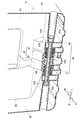
まず、エンジン駆動作業機10で排気音を減少させる例について説明する。
図13に示すように、排気流路66からマフラー67に排気ガスが矢印Jの如く導かれる。マフラー67に導かれた排気ガスがテールパイプ68を経て排気口68aから空間21bに矢印Kの如く排気される。
排気された排気ガスが空間21bを経てルーバ121に矢印Lの如く導かれる。ルーバ121に導かれた排気ガスは、ルーバ121や排出口37を経て外装ケース12の外部14に矢印Mの如く排出される。
First, an example in which the engine-driven
As shown in FIG. 13, the exhaust gas is guided from the
The exhaust gas exhausted is guided to the
ここで、排気口68aの上方にルーバ121や排出口37が配置される。よって、排気口68aが排出口37から下方に離される。これにより、排気口68aの排気ガスを排出口37やルーバ121から離れた位置に排気できる。
また、排気口68aが排出口37の開口方向(矢印A方向)に交差するように開口されることにより、排気音の進行方向から排出口37の向きをずらすことができる。
Here, the
Further, by opening the
このように、排気ガスを排出口37やルーバ121から離れた位置に排気し、排気音の進行方向から排出口37の向きをずらすことにより、プロテクタ117で排気音の遮音を高めることができる。
さらに、プロテクタ117の内面117aに吸音材118が取り付けられることにより、排気口68aから排気される排気音を吸音材118で吸音できる。
Thus, the exhaust gas is exhausted to a position away from the
Furthermore, the
このように、プロテクタ117で排気音を遮音し、かつ、排気音を吸音材118で吸音することにより、排気音(すなわち、騒音)を一層良好に低減できる。これにより、カバーユニット20の外部(すなわち、外装ケース12の外部14)に伝わる排気音を小さく抑えることができる。
As described above, the exhaust sound is insulated by the
つぎに、プロテクタ117や吸音材118を冷却する例について説明する。
図13に示すように、冷却ファン17(図10参照)から送風された冷却風がシリンダ42を経て導風板84側に矢印Nの如く導かれる。導風板84側に導かれた冷却風が、導風板84でマフラー67側(すなわち、下方)へ向けて矢印Oの如く導かれる。
特に、導風板84が後方へ向けて下り勾配に傾斜されている。よって、導風板84側に導かれた冷却風が、導風板84でマフラー67側へ向けて効率よく導かれる。
Next, an example of cooling the
As shown in FIG. 13, the cooling air blown from the cooling fan 17 (see FIG. 10) is guided to the
In particular, the
マフラー側に導かれた冷却風は、マフラー67とエンジン15との間の空間21dを経てマフラー67の下部67aまで矢印Pの如く導かれる。マフラー67の下部67aまで導かれた冷却風が下方空間21cを経て空間21bに矢印Qの如く導かれる。
The cooling air guided to the muffler side is guided as indicated by an arrow P to the
空間21bに冷却風を導くことにより、テールパイプ68や、プロテクタ117および吸音材118に冷却風を導くことができる。これにより、プロテクタ117および吸音材118が排気熱により劣化することを防止できる。
空間21bに導かれた冷却風がルーバ121や排気口68aを経て外装ケース12の外部14に矢印Rの如く排出される。
By guiding the cooling air to the
The cooling air guided to the
なお、本発明に係るエンジン駆動作業機は、前述した実施例に限定されるものではなく適宜変更、改良などが可能である。
例えば、前記実施例では、吸気ポート44に気化器61を直接設けた例について説明したが、これに限定するものではなく、吸気ポート44に吸気流路(吸気マニホールド)を介して気化器61を連通させることも可能である。
この場合でも、吸気ポート44側に気化器61が配置されるので、気化器61を吸気ポート44に連通する吸気流路を大きく湾曲させる必要がなく簡素化できる。これにより、吸気流路を流れる吸気の通気抵抗が小さく抑えられ、エンジンの出力を確保できる。
The engine-driven work machine according to the present invention is not limited to the above-described embodiments, and can be changed or improved as appropriate.
For example, in the above-described embodiment, the example in which the
Even in this case, since the
また、前記実施例では、外装ケース12の前後方向に対してクランクシャフト41を直交させて配置する例について説明したが、これに限定するものではない。例えば、外装ケース12の前後方向に対してクランクシャフト41を傾斜状に交差させることも可能である。
Moreover, although the said Example demonstrated the example which has arrange | positioned the
さらに、前記実施例で示した発電機、外装ケース、エンジン、冷却ファン、排出口、マフラー、テールパイプ、テールパイプの排気口、導風板、プロテクタおよび吸音材などの形状や構成は例示したものに限定するものではなく適宜変更が可能である。 Further, the shape and configuration of the generator, exterior case, engine, cooling fan, exhaust port, muffler, tail pipe, tail pipe exhaust port, wind guide plate, protector, and sound absorbing material shown in the above embodiment are illustrated. It is not limited to this, and can be changed as appropriate.
本発明は、外装ケースの内部にエンジンとマフラーとが収納され、マフラーのテールパイプから排気ガスを排気するエンジン駆動作業機への適用に好適である。 The present invention is suitable for application to an engine-driven work machine in which an engine and a muffler are housed in an exterior case and exhaust gas is exhausted from a tail pipe of the muffler.
10 発電機(エンジン駆動作業機)
12 外装ケース
13 外装ケースの内部
15 エンジン
17 冷却ファン
37 排出口
67 マフラー
67a マフラーの下部
68 テールパイプ
68a テールパイプの排気口
84 導風板
117 プロテクタ
117a プロテクタの内面
118 吸音材
10 Generator (Engine-driven work machine)
DESCRIPTION OF
Claims (3)
前記マフラーの下部に設けられるテールパイプと、
該テールパイプの上方に配置され、前記外装ケースに形成された排出口と、
該排出口に対向するように配置され、冷却ファンから送風される冷却風を前記マフラーの下方へ導く導風板と、
を備える、ことを特徴とするエンジン駆動作業機。 In the engine-driven work machine in which the engine and muffler are housed inside the exterior case,
A tail pipe provided at the bottom of the muffler;
A discharge port disposed above the tail pipe and formed in the exterior case;
An air guide plate that is arranged to face the exhaust port and guides the cooling air blown from the cooling fan to the lower side of the muffler;
An engine-driven work machine comprising:
前記マフラーおよび前記テールパイプを覆うプロテクタと、
該プロテクタの内面に設けられる吸音材と、
を備える、請求項1記載のエンジン駆動作業機。 The engine driven work machine further includes:
A protector covering the muffler and the tail pipe;
A sound absorbing material provided on the inner surface of the protector;
The engine-driven work machine according to claim 1, comprising:
該テールパイプの排気口が前記排出口の開口方向に対して交差するように開口される、請求項1または請求項2記載のエンジン駆動作業機。 The tail pipe is
The engine-driven work machine according to claim 1 or 2, wherein an exhaust port of the tail pipe is opened so as to intersect an opening direction of the discharge port.
Priority Applications (4)
| Application Number | Priority Date | Filing Date | Title |
|---|---|---|---|
| JP2016051821A JP6687433B2 (en) | 2016-03-16 | 2016-03-16 | Engine driven work machine |
| EP17154766.4A EP3219945B1 (en) | 2016-03-16 | 2017-02-06 | Engine-driven working machine |
| CN201710102213.9A CN107201948B (en) | 2016-03-16 | 2017-02-24 | engine driven work machine |
| US15/454,489 US10224783B2 (en) | 2016-03-16 | 2017-03-09 | Engine-driven working machine |
Applications Claiming Priority (1)
| Application Number | Priority Date | Filing Date | Title |
|---|---|---|---|
| JP2016051821A JP6687433B2 (en) | 2016-03-16 | 2016-03-16 | Engine driven work machine |
Publications (2)
| Publication Number | Publication Date |
|---|---|
| JP2017166399A true JP2017166399A (en) | 2017-09-21 |
| JP6687433B2 JP6687433B2 (en) | 2020-04-22 |
Family
ID=57965818
Family Applications (1)
| Application Number | Title | Priority Date | Filing Date |
|---|---|---|---|
| JP2016051821A Expired - Fee Related JP6687433B2 (en) | 2016-03-16 | 2016-03-16 | Engine driven work machine |
Country Status (4)
| Country | Link |
|---|---|
| US (1) | US10224783B2 (en) |
| EP (1) | EP3219945B1 (en) |
| JP (1) | JP6687433B2 (en) |
| CN (1) | CN107201948B (en) |
Families Citing this family (12)
| Publication number | Priority date | Publication date | Assignee | Title |
|---|---|---|---|---|
| CN111636958A (en) * | 2018-03-30 | 2020-09-08 | 本田技研工业株式会社 | General Purpose Engine |
| JP7061675B2 (en) * | 2018-08-30 | 2022-04-28 | 本田技研工業株式会社 | General-purpose engine |
| JP2020105997A (en) * | 2018-12-28 | 2020-07-09 | 本田技研工業株式会社 | Power generator |
| US11437887B2 (en) * | 2019-09-12 | 2022-09-06 | Rv Mobile Power, Llc | Ventilation for electric generator system |
| US11530636B2 (en) | 2020-05-06 | 2022-12-20 | Kohler Co. | Engine exhaust heat management system |
| USD1085007S1 (en) | 2023-10-11 | 2025-07-22 | Northern Tool & Equipment Company, Inc. | Generator assembly |
| USD1085010S1 (en) | 2023-10-11 | 2025-07-22 | Northern Tool & Equipment Company, Inc. | Generator assembly |
| USD1085006S1 (en) | 2023-10-11 | 2025-07-22 | Northern Tool & Equipment Company, Inc. | Generator assembly |
| USD1085008S1 (en) | 2023-10-11 | 2025-07-22 | Northern Tool & Equipment Company, Inc. | Generator assembly |
| USD1085011S1 (en) | 2023-10-11 | 2025-07-22 | Northern Tool & Equipment Company, Inc. | Generator assembly |
| USD1085009S1 (en) | 2023-10-11 | 2025-07-22 | Northern Tool & Equipment Company, Inc. | Generator assembly |
| USD1085012S1 (en) | 2023-10-11 | 2025-07-22 | Northern Tool & Equipment Company, Inc. | Generator assembly |
Citations (7)
| Publication number | Priority date | Publication date | Assignee | Title |
|---|---|---|---|---|
| JPS59175638U (en) * | 1983-05-11 | 1984-11-24 | 本田技研工業株式会社 | Soundproof cooling structure for motor generator |
| JPS59181232U (en) * | 1983-05-20 | 1984-12-03 | 本田技研工業株式会社 | Soundproof structure of motor generator |
| JPH0688524A (en) * | 1992-09-08 | 1994-03-29 | Kubota Corp | Engine part structure of farm working vehicle |
| JPH1136881A (en) * | 1997-07-24 | 1999-02-09 | Honda Motor Co Ltd | Engine generator |
| JP2005042644A (en) * | 2003-07-24 | 2005-02-17 | Fuji Heavy Ind Ltd | Engine generator |
| JP2008051024A (en) * | 2006-08-25 | 2008-03-06 | Honda Motor Co Ltd | Engine-driven work machine |
| JP2013024077A (en) * | 2011-07-19 | 2013-02-04 | Kobelco Contstruction Machinery Ltd | Exhaust structure for construction machine |
Family Cites Families (14)
| Publication number | Priority date | Publication date | Assignee | Title |
|---|---|---|---|---|
| JPS59181232A (en) | 1983-03-31 | 1984-10-15 | Nippon Steel Chem Co Ltd | Method for producing o-methylated phenols |
| GB2141782B (en) * | 1983-05-11 | 1987-01-07 | Honda Motor Co Ltd | Portable engine-generator sets |
| US4677940A (en) * | 1985-08-09 | 1987-07-07 | Kohler Co. | Cooling system for a compact generator |
| US4741411A (en) * | 1987-01-14 | 1988-05-03 | Deere & Company | Muffler system |
| JP2664102B2 (en) * | 1991-07-11 | 1997-10-15 | 株式会社クボタ | Power structure of lawn mower |
| US5689953A (en) * | 1995-03-29 | 1997-11-25 | Kubota Corporation | Cooling system for a liquid-cooled engine |
| JP3531716B2 (en) * | 1998-04-17 | 2004-05-31 | 本田技研工業株式会社 | Engine driven work machine |
| JP2001026944A (en) * | 1999-07-16 | 2001-01-30 | Kobelco Contstruction Machinery Ltd | Exhaust system structure for construction equipment |
| JP4313133B2 (en) * | 2003-09-19 | 2009-08-12 | 川崎重工業株式会社 | Engine cooling structure |
| JP4767791B2 (en) * | 2006-08-25 | 2011-09-07 | 本田技研工業株式会社 | Engine-driven work machine |
| CA2668536C (en) * | 2008-06-27 | 2016-11-15 | Honda Motor Co., Ltd. | Engine-driven power generator apparatus |
| CN101603461B (en) * | 2009-04-30 | 2011-07-20 | 蔡建平 | Mute diesel generator set |
| CN202228183U (en) * | 2011-08-19 | 2012-05-23 | 浙江康思特动力机械有限公司 | Portable engine generator |
| JP6628651B2 (en) * | 2016-03-15 | 2020-01-15 | 本田技研工業株式会社 | Engine driven work machine |
-
2016
- 2016-03-16 JP JP2016051821A patent/JP6687433B2/en not_active Expired - Fee Related
-
2017
- 2017-02-06 EP EP17154766.4A patent/EP3219945B1/en not_active Not-in-force
- 2017-02-24 CN CN201710102213.9A patent/CN107201948B/en not_active Expired - Fee Related
- 2017-03-09 US US15/454,489 patent/US10224783B2/en active Active
Patent Citations (7)
| Publication number | Priority date | Publication date | Assignee | Title |
|---|---|---|---|---|
| JPS59175638U (en) * | 1983-05-11 | 1984-11-24 | 本田技研工業株式会社 | Soundproof cooling structure for motor generator |
| JPS59181232U (en) * | 1983-05-20 | 1984-12-03 | 本田技研工業株式会社 | Soundproof structure of motor generator |
| JPH0688524A (en) * | 1992-09-08 | 1994-03-29 | Kubota Corp | Engine part structure of farm working vehicle |
| JPH1136881A (en) * | 1997-07-24 | 1999-02-09 | Honda Motor Co Ltd | Engine generator |
| JP2005042644A (en) * | 2003-07-24 | 2005-02-17 | Fuji Heavy Ind Ltd | Engine generator |
| JP2008051024A (en) * | 2006-08-25 | 2008-03-06 | Honda Motor Co Ltd | Engine-driven work machine |
| JP2013024077A (en) * | 2011-07-19 | 2013-02-04 | Kobelco Contstruction Machinery Ltd | Exhaust structure for construction machine |
Also Published As
| Publication number | Publication date |
|---|---|
| US20170271942A1 (en) | 2017-09-21 |
| EP3219945B1 (en) | 2018-10-17 |
| EP3219945A1 (en) | 2017-09-20 |
| JP6687433B2 (en) | 2020-04-22 |
| US10224783B2 (en) | 2019-03-05 |
| CN107201948A (en) | 2017-09-26 |
| CN107201948B (en) | 2019-08-30 |
Similar Documents
| Publication | Publication Date | Title |
|---|---|---|
| JP6687433B2 (en) | Engine driven work machine | |
| JP2017166400A (en) | Engine drive work machine | |
| JP6687432B2 (en) | Engine driven work machine | |
| AU2004255717B2 (en) | Engine-driven electric generator | |
| CA2538275C (en) | Engine-driven working machine | |
| AU2004255716B2 (en) | Engine-driven electric generator | |
| CN1129707C (en) | Portable generator | |
| JP2008255831A (en) | Soundproof engine generator | |
| JP4546352B2 (en) | Swing tricycle | |
| JP3871829B2 (en) | Engine generator | |
| JP2006009809A (en) | Engine working machine | |
| JP4466998B2 (en) | Fuel tank support structure for forced air cooling engine | |
| JP6193713B2 (en) | Air-cooled engine | |
| JP2005344575A (en) | Forced air cooling engine | |
| JP2020070750A (en) | Sound insulation structure of internal combustion engine | |
| JP2005282581A (en) | Engine working machine | |
| JP2006009808A (en) | Engine working machine |
Legal Events
| Date | Code | Title | Description |
|---|---|---|---|
| RD02 | Notification of acceptance of power of attorney |
Free format text: JAPANESE INTERMEDIATE CODE: A7422 Effective date: 20160406 |
|
| A621 | Written request for application examination |
Free format text: JAPANESE INTERMEDIATE CODE: A621 Effective date: 20181127 |
|
| A131 | Notification of reasons for refusal |
Free format text: JAPANESE INTERMEDIATE CODE: A131 Effective date: 20191001 |
|
| A977 | Report on retrieval |
Free format text: JAPANESE INTERMEDIATE CODE: A971007 Effective date: 20190930 |
|
| A521 | Request for written amendment filed |
Free format text: JAPANESE INTERMEDIATE CODE: A523 Effective date: 20191128 |
|
| TRDD | Decision of grant or rejection written | ||
| A01 | Written decision to grant a patent or to grant a registration (utility model) |
Free format text: JAPANESE INTERMEDIATE CODE: A01 Effective date: 20200317 |
|
| A61 | First payment of annual fees (during grant procedure) |
Free format text: JAPANESE INTERMEDIATE CODE: A61 Effective date: 20200402 |
|
| R150 | Certificate of patent or registration of utility model |
Ref document number: 6687433 Country of ref document: JP Free format text: JAPANESE INTERMEDIATE CODE: R150 |
|
| LAPS | Cancellation because of no payment of annual fees |