JP2017166336A - Variable displacement swash plate compressor - Google Patents

Variable displacement swash plate compressor Download PDF

Info

Publication number
JP2017166336A
JP2017166336A JP2016049793A JP2016049793A JP2017166336A JP 2017166336 A JP2017166336 A JP 2017166336A JP 2016049793 A JP2016049793 A JP 2016049793A JP 2016049793 A JP2016049793 A JP 2016049793A JP 2017166336 A JP2017166336 A JP 2017166336A
Authority
JP
Japan
Prior art keywords
chamber
passage
swash plate
control
path
Prior art date
Legal status (The legal status is an assumption and is not a legal conclusion. Google has not performed a legal analysis and makes no representation as to the accuracy of the status listed.)
Pending
Application number
JP2016049793A
Other languages
Japanese (ja)
Inventor
裕之 仲井間
Hiroyuki Nakaima
裕之 仲井間
山本 真也
Shinya Yamamoto
真也 山本
隆容 鈴木
Takayasu Suzuki
隆容 鈴木
久弥 近藤
Hisaya Kondo
久弥 近藤
和也 本田
Kazuya Honda
和也 本田
Current Assignee (The listed assignees may be inaccurate. Google has not performed a legal analysis and makes no representation or warranty as to the accuracy of the list.)
Toyota Industries Corp
Original Assignee
Toyota Industries Corp
Priority date (The priority date is an assumption and is not a legal conclusion. Google has not performed a legal analysis and makes no representation as to the accuracy of the date listed.)
Filing date
Publication date
Application filed by Toyota Industries Corp filed Critical Toyota Industries Corp
Priority to JP2016049793A priority Critical patent/JP2017166336A/en
Publication of JP2017166336A publication Critical patent/JP2017166336A/en
Pending legal-status Critical Current

Links

Images

Landscapes

  • Compressors, Vaccum Pumps And Other Relevant Systems (AREA)
  • Control Of Positive-Displacement Pumps (AREA)

Abstract

PROBLEM TO BE SOLVED: To provide a variable displacement swash plate compressor capable of developing high controllability.SOLUTION: The compressor includes a housing 1 in which a first suction chamber 27a, a second suction chamber 27b, a first discharge chamber 29a, and a second discharge chamber 29b are formed. The compressor further includes a control pressure chamber 13c, and a control mechanism 15. The control mechanism 15 has a control path 55 communicated with the control pressure chamber 13c, a first passage 59a communicating the control path 55 with the first discharge chamber 29a, and a second passage 59b communicating the control path 55 with the second suction chamber 27b. The control mechanism 15 also has a control valve 24a capable of changing the opening of the second passage 59b, and a restriction passage 20 as a restriction for restricting the opening of the first passage 59a.SELECTED DRAWING: Figure 1

Description

本発明は容量可変型斜板式圧縮機に関する。   The present invention relates to a variable displacement swash plate compressor.

特許文献1に従来の容量可変型斜板式圧縮機(以下、単に圧縮機という。)が開示されている。この圧縮機は、ハウジングと、駆動軸と、斜板と、リンク機構と、複数のピストンと、区画体と、移動体と、制御圧室と、制御機構とを備えている。ハウジングは、フロントハウジング、リヤハウジング及びシリンダブロックによって構成されている。フロントハウジングは、斜板の一面側に配置されており、第1吸入室と第1吐出室とが形成されている。リヤハウジングは斜板の他面側に配置されており、第2吸入室と第2吐出室と圧力調整室とが形成されている。シリンダブロックは、フロントハウジングとリヤハウジングとの間に配置されている。シリンダブロックには、第1吸入室及び第1吐出室に連通する複数の第1シリンダボアと、第2吸入室及び第2吐出室に連通する複数の第2シリンダボアとが形成されている他、斜板室が形成されている。   Patent Document 1 discloses a conventional variable displacement swash plate compressor (hereinafter simply referred to as a compressor). The compressor includes a housing, a drive shaft, a swash plate, a link mechanism, a plurality of pistons, a partition body, a moving body, a control pressure chamber, and a control mechanism. The housing includes a front housing, a rear housing, and a cylinder block. The front housing is disposed on one side of the swash plate, and has a first suction chamber and a first discharge chamber. The rear housing is disposed on the other side of the swash plate, and a second suction chamber, a second discharge chamber, and a pressure adjustment chamber are formed. The cylinder block is disposed between the front housing and the rear housing. The cylinder block has a plurality of first cylinder bores communicating with the first suction chamber and the first discharge chamber and a plurality of second cylinder bores communicating with the second suction chamber and the second discharge chamber. A board chamber is formed.

駆動軸はハウジングに回転可能に支承されている。斜板は、斜板室内に設けられており、駆動軸の回転によって回転可能となっている。リンク機構は、駆動軸と斜板との間に設けられており、斜板の傾斜角度の変更を許容する。ここで、傾斜角度とは、駆動軸の回転軸心に直交する方向に対する斜板の角度である。各ピストンは、第1頭部と第2頭部とを有している。第1頭部は、第1シリンダボア内を往復動して、第1シリンダボア内に第1圧縮室を区画する。第2頭部は、第2シリンダボア内を往復動して、第2シリンダボア内に第2圧縮室を区画する。各ピストンと斜板との間には、変換機構としてのシューが設けられている。シューは、ピストン毎に対をなしており、斜板の回転によって、傾斜角度に応じたストロークで各ピストンを往復動させる。区画体は、駆動軸に設けられており、斜板室内で駆動軸と一体回転可能となっている。移動体は、駆動軸に設けられており、斜板室内で駆動軸と一体回転可能となっているとともに、回転軸心方向に移動して傾斜角度を変更する。制御圧室は、区画体と移動体とにより区画されており、内部の圧力によって移動体を移動させる。   The drive shaft is rotatably supported on the housing. The swash plate is provided in the swash plate chamber and can be rotated by rotation of the drive shaft. The link mechanism is provided between the drive shaft and the swash plate, and allows the inclination angle of the swash plate to be changed. Here, the inclination angle is an angle of the swash plate with respect to a direction orthogonal to the rotation axis of the drive shaft. Each piston has a first head and a second head. The first head reciprocates in the first cylinder bore to partition the first compression chamber in the first cylinder bore. The second head reciprocates in the second cylinder bore to partition the second compression chamber in the second cylinder bore. A shoe as a conversion mechanism is provided between each piston and the swash plate. The shoe makes a pair for each piston, and reciprocates each piston with a stroke corresponding to the inclination angle by the rotation of the swash plate. The partition is provided on the drive shaft, and can rotate integrally with the drive shaft in the swash plate chamber. The moving body is provided on the drive shaft, can rotate integrally with the drive shaft in the swash plate chamber, and moves in the direction of the rotation axis to change the tilt angle. The control pressure chamber is partitioned by a partition body and a moving body, and moves the moving body by an internal pressure.

制御機構は、制御路、給気路、抽気路、制御弁及びオリフィスを有している。制御路は、駆動軸の内部に形成されており、制御圧室と圧力調整室とに連通している。給気路は第2吐出室と圧力調整室とに連通している。抽気路は第2吸入室と圧力調整室とに連通している。制御弁は、第2吸入室の圧力により自己の開度を変更可能となっている。オリフィスは抽気路に設けられている。制御機構は、圧力調整室内の圧力を制御することによって、制御圧室内の圧力を制御する。   The control mechanism has a control path, an air supply path, an extraction path, a control valve, and an orifice. The control path is formed inside the drive shaft and communicates with the control pressure chamber and the pressure adjustment chamber. The air supply path communicates with the second discharge chamber and the pressure adjustment chamber. The extraction passage communicates with the second suction chamber and the pressure adjustment chamber. The control valve can change its opening degree by the pressure in the second suction chamber. The orifice is provided in the bleed passage. The control mechanism controls the pressure in the control pressure chamber by controlling the pressure in the pressure adjustment chamber.

この圧縮機では、制御機構の制御弁が自己の開度を大きくすれば、第2吐出室内の圧力によって、圧力調整室内の圧力が増大する。このため、制御圧室の圧力が増大し、移動体が区画体から離れるように回転軸心方向に移動する。これにより、リンク機構は、斜板の傾斜角度を増大させる。こうして、この圧縮機では、駆動軸の1回転当たりの吐出容量が増大する。一方、制御弁が自己の開度を小さくすれば、圧力調整室内の圧力が減少するため、制御圧室の圧力も減少する。これにより、移動体が区画体に近づくように移動するため、リンク機構は、斜板の傾斜角度を減少させる。こうして、この圧縮機では、駆動軸の1回転当たりの吐出容量が減少する。   In this compressor, if the control valve of the control mechanism increases its own opening, the pressure in the pressure adjustment chamber increases due to the pressure in the second discharge chamber. For this reason, the pressure of the control pressure chamber increases, and the moving body moves in the direction of the rotation axis so as to move away from the partitioning body. Thereby, the link mechanism increases the inclination angle of the swash plate. Thus, in this compressor, the discharge capacity per rotation of the drive shaft increases. On the other hand, if the control valve reduces its own opening, the pressure in the pressure adjustment chamber decreases, so the pressure in the control pressure chamber also decreases. Thereby, since a mobile body moves so that a division body may be approached, a link mechanism reduces the inclination-angle of a swash plate. Thus, in this compressor, the discharge capacity per rotation of the drive shaft is reduced.

特開2014−92104号公報JP 2014-92104 A

この種の圧縮機では、必要に応じて素早く吐出容量を増減し得る高い制御性が要求される。この点、上記従来の圧縮機では、制御圧室が圧力調整室を介して第2吸入室及び第2吐出室と連通していることから、吐出容量を増減するに当たって、圧力調整室内の圧力を制御する必要がある。このため、この圧縮機では、制御弁が開度を変更した際、吐出容量が増減されるまでに遅れが生じ易い。   This type of compressor is required to have high controllability that can quickly increase or decrease the discharge capacity as needed. In this regard, in the above-described conventional compressor, the control pressure chamber communicates with the second suction chamber and the second discharge chamber via the pressure adjustment chamber. Therefore, when the discharge capacity is increased or decreased, the pressure in the pressure adjustment chamber is reduced. Need to control. For this reason, in this compressor, when the control valve changes the opening, a delay is likely to occur until the discharge capacity is increased or decreased.

本発明は、上記従来の実情に鑑みてなされたものであって、高い制御性を発揮可能な容量可変型斜板式圧縮機を提供することを解決すべき課題としている。   The present invention has been made in view of the above-described conventional situation, and an object to be solved is to provide a variable displacement swash plate compressor capable of exhibiting high controllability.

本発明の容量可変型斜板式圧縮機は、吸入室、吐出室、斜板室及び複数のシリンダボアが形成されたハウジングと、
前記ハウジングに回転可能に支承された駆動軸と、
前記斜板室内に配置されて前記駆動軸とともに回転される斜板と、
前記駆動軸の回転軸心に直交する方向に対する前記斜板の傾斜角度の変更を許容するリンク機構と、
前記各シリンダボアに収納され、前記斜板の回転によって前記傾斜角度に応じたストロークで往復動して前記各シリンダボア内に圧縮室を形成するピストンと、
前記斜板室内で前記駆動軸と一体回転可能に設けられた区画体と、
前記斜板室内で前記駆動軸と一体回転可能であり、かつ前記区画体に対して前記回転軸心方向に移動して前記傾斜角度を変更する移動体と、
前記区画体と前記移動体とにより区画され、内部の圧力によって前記移動体を移動させる制御圧室と、
前記制御圧室内の圧力を制御する制御機構とを備え、
前記吸入室は、前記斜板の一面側に位置する第1吸入室と、前記斜板の他面側に位置する第2吸入室とからなり、
前記吐出室は、前記斜板の前記一面側に位置する第1吐出室と、前記斜板の前記他面側に位置する第2吐出室とからなり、
前記各シリンダボアは、前記斜板の前記一面側に設けられ、前記第1吸入室及び前記第1吐出室と連通する第1シリンダボアと、前記斜板の前記他面側に設けられ、前記第2吸入室及び前記第2吐出室と連通する第2シリンダボアとからなり、
前記各ピストンは、前記第1シリンダボア内を往復動して、前記第1シリンダボア内に第1圧縮室を区画する第1頭部と、前記第2シリンダボア内を往復動して、前記第2シリンダボア内に第2圧縮室を区画する第2頭部とを有し、
前記制御機構は、前記駆動軸の内部に形成され、前記制御圧室に連通する制御路と、
前記ハウジング及び前記駆動軸の少なくとも一方に形成され、前記制御路を前記第1吐出室又は前記第1吸入室に連通させる第1通路と、
前記ハウジング及び前記駆動軸の少なくとも一方に形成され、前記第1通路が前記第1吐出室に連通すれば前記制御路を前記第2吸入室に連通させ、前記第1通路が前記第1吸入室に連通すれば前記制御路を前記第2吐出室に連通させる第2通路と、
前記第1通路及び前記第2通路のうちの一方側の通路に設けられ、前記一方側の通路の開度を変更可能な制御弁と、
前記第1通路及び前記第2通路のうちの他方側の通路に設けられ、前記他方側の通路の開度を絞る絞り又は前記他方側の通路の開度を変更可能な前記制御弁とを有していることを特徴とする。
The capacity variable swash plate compressor of the present invention includes a suction chamber, a discharge chamber, a swash plate chamber and a housing in which a plurality of cylinder bores are formed,
A drive shaft rotatably supported on the housing;
A swash plate disposed in the swash plate chamber and rotated together with the drive shaft;
A link mechanism that allows a change in the inclination angle of the swash plate with respect to the direction orthogonal to the rotational axis of the drive shaft;
A piston that is housed in each cylinder bore and reciprocates at a stroke according to the tilt angle by rotation of the swash plate to form a compression chamber in each cylinder bore;
A partition provided in the swash plate chamber so as to be integrally rotatable with the drive shaft;
A movable body that is integrally rotatable with the drive shaft in the swash plate chamber and that moves in the direction of the rotational axis relative to the partition body to change the tilt angle;
A control pressure chamber that is partitioned by the partition body and the moving body and moves the moving body by an internal pressure;
A control mechanism for controlling the pressure in the control pressure chamber,
The suction chamber comprises a first suction chamber located on one side of the swash plate and a second suction chamber located on the other side of the swash plate,
The discharge chamber is composed of a first discharge chamber located on the one surface side of the swash plate and a second discharge chamber located on the other surface side of the swash plate,
The cylinder bores are provided on the one surface side of the swash plate, provided on the other surface side of the swash plate, a first cylinder bore communicating with the first suction chamber and the first discharge chamber, and the second A second cylinder bore communicating with the suction chamber and the second discharge chamber;
Each piston reciprocates within the first cylinder bore, reciprocates within the first cylinder bore and a first head that defines a first compression chamber, and the second cylinder bore, and the second cylinder bore. A second head that defines a second compression chamber therein,
The control mechanism is formed inside the drive shaft and communicates with the control pressure chamber;
A first passage formed in at least one of the housing and the drive shaft and communicating the control path with the first discharge chamber or the first suction chamber;
If formed in at least one of the housing and the drive shaft, and the first passage communicates with the first discharge chamber, the control passage communicates with the second suction chamber, and the first passage communicates with the first suction chamber. A second passage for communicating the control path with the second discharge chamber if communicating with the second discharge chamber;
A control valve provided in one of the first and second passages and capable of changing an opening of the one passage;
Provided in a passage on the other side of the first passage and the second passage, and has a throttle for restricting the opening of the other passage or the control valve capable of changing the opening of the other passage. It is characterized by that.

本発明の圧縮機では、第1通路が制御路を第1吐出室に連通させれば、第2通路は制御路を第2吸入室に連通させる。これにより、制御圧室内には第1通路及び制御路を経た第1吐出室内の冷媒が直接導入されるとともに、制御圧室内の冷媒は制御路及び第2通路を経て第2吸入室へ直接導出される。また、第1通路が制御路を第1吸入室に連通させれば、第2通路は制御路を第2吐出室に連通させる。これにより、制御圧室内には第2通路及び制御路を経た第2吐出室内の冷媒が直接導入されるとともに、制御圧室内の冷媒は制御路及び第1通路を経て第1吸入室へ直接導出される。そして、第1通路及び第2通路のうちの一方側の通路には制御弁が設けられ、第1通路及び第2通路のうちの他方側の通路には絞り又は制御弁が設けられる。これにより、制御圧室内に導入される冷媒の流量と、第2吸入室へ導出される冷媒の流量とが調整される。こうして、この圧縮機では、制御圧室内の圧力が調整される。   In the compressor according to the present invention, when the first passage communicates the control path with the first discharge chamber, the second passage communicates the control path with the second suction chamber. As a result, the refrigerant in the first discharge chamber that has passed through the first passage and the control passage is directly introduced into the control pressure chamber, and the refrigerant in the control pressure chamber is directly led out to the second suction chamber through the control passage and the second passage. Is done. In addition, if the first passage communicates the control path with the first suction chamber, the second passage communicates the control path with the second discharge chamber. As a result, the refrigerant in the second discharge chamber that has passed through the second passage and the control passage is directly introduced into the control pressure chamber, and the refrigerant in the control pressure chamber is directly led out to the first suction chamber through the control passage and the first passage. Is done. A control valve is provided in one of the first passage and the second passage, and a throttle or control valve is provided in the other passage of the first passage and the second passage. Thereby, the flow rate of the refrigerant introduced into the control pressure chamber and the flow rate of the refrigerant led out to the second suction chamber are adjusted. Thus, in this compressor, the pressure in the control pressure chamber is adjusted.

こうして、この圧縮機では、制御圧室が圧力調整室を介して第1吸入室及び第2吐出室と連通したり、制御圧室が圧力調整室を介して第2吸入室及び第1吐出室と連通したりする場合と比較して、制御圧室内の圧力を素早く調整することができる。このため、この圧縮機では、必要に応じて移動体が斜板の傾斜角度を素早く変更できるため、素早く吐出容量を増減することができる。   Thus, in this compressor, the control pressure chamber communicates with the first suction chamber and the second discharge chamber via the pressure adjustment chamber, or the control pressure chamber communicates with the second suction chamber and the first discharge chamber via the pressure adjustment chamber. The pressure in the control pressure chamber can be quickly adjusted as compared with the case of communicating with the control pressure chamber. For this reason, in this compressor, since a moving body can change the inclination-angle of a swash plate quickly as needed, discharge capacity can be increased / decreased rapidly.

したがって、本発明の容量可変型斜板式圧縮機は高い制御性を発揮する。   Therefore, the variable capacity swash plate compressor of the present invention exhibits high controllability.

本発明の圧縮機において、第1通路は、制御路を第1吐出室に連通させ得る。また、第2通路は、制御路を第2吸入室に連通させ得る。さらに、制御弁は、第2通路に設けられ得る。また、第1通路には、絞りが設けられ得る。そして、制御路には、第1吐出室の冷媒が制御圧室へ至る給気経路と、制御圧室の冷媒が第2吸入室へ至る抽気経路と、給気経路と抽気経路とを隔てる隔壁とが形成されていることが好ましい。   In the compressor of the present invention, the first passage can communicate the control path with the first discharge chamber. The second passage can connect the control path to the second suction chamber. Furthermore, a control valve can be provided in the second passage. The first passage can be provided with a throttle. The control path includes an air supply path for the refrigerant in the first discharge chamber to reach the control pressure chamber, an air extraction path for the refrigerant in the control pressure chamber to the second suction chamber, and a partition that separates the air supply path and the air extraction path. And are preferably formed.

この場合には、制御圧室内の圧力を調整するに当たって、制御弁が第2通路の開度を大きくすることにより、制御圧室内の圧力を素早く低下させることが可能となる。また、制御路に隔壁が形成されることにより、給気経路を流通する冷媒が制御圧室内に至らずに抽気経路へ流通することを防止できる。これらのため、この圧縮機では制御圧室内の圧力を好適に調整することができ、吐出容量を好適に増減することができる。また、この圧縮機では、第1通路に絞りが設けられることにより、第1通路及び第2通路の両方に制御弁が設けられる場合に比べて、製造コストを低廉化することが可能となる。   In this case, when adjusting the pressure in the control pressure chamber, the control valve increases the opening of the second passage, whereby the pressure in the control pressure chamber can be quickly reduced. Further, by forming the partition wall in the control path, it is possible to prevent the refrigerant flowing through the air supply path from flowing into the extraction path without reaching the control pressure chamber. For these reasons, in this compressor, the pressure in the control pressure chamber can be suitably adjusted, and the discharge capacity can be suitably increased or decreased. Further, in this compressor, by providing the throttle in the first passage, the manufacturing cost can be reduced as compared with the case where the control valves are provided in both the first passage and the second passage.

また、本発明の圧縮機において、第1通路は、制御路を第1吸入室に連通させ得る。さらに、第2通路は、制御路を第2吐出室に連通させ得る。また、制御弁は、第2通路に設けられ得る。さらに、第1通路には、絞りが設けられ得る。そして、制御路には、第2吐出室の冷媒が制御圧室へ至る給気経路と、制御圧室の冷媒が第1吸入室へ至る抽気経路と、給気経路と抽気経路とを隔てる隔壁とが形成されていることも好ましい。   In the compressor of the present invention, the first passage can connect the control path to the first suction chamber. Further, the second passage can connect the control path to the second discharge chamber. The control valve can be provided in the second passage. Furthermore, a throttle can be provided in the first passage. The control path includes an air supply path for the refrigerant in the second discharge chamber to reach the control pressure chamber, an air extraction path for the refrigerant in the control pressure chamber to the first suction chamber, and a partition that separates the air supply path and the air extraction path. It is also preferable that these are formed.

この場合には、制御圧室内の圧力を調整するに当たって、制御弁が第2通路の開度を大きくすることにより、制御圧室内の圧力を素早く増大させることが可能となる。また、隔壁によって、給気経路を流通する冷媒が制御圧室に至らずに抽気経路へ流通することを防止できる。これらのため、この圧縮機でも制御圧室内の圧力を好適に調整することができ、吐出容量を好適に増減することができる。また、この圧縮機でも、第1通路及び第2通路の両方に制御弁が設けられる場合に比べて、製造コストを低廉化することが可能となる。   In this case, when adjusting the pressure in the control pressure chamber, the control valve increases the opening of the second passage, so that the pressure in the control pressure chamber can be quickly increased. Further, the partition wall can prevent the refrigerant flowing through the air supply path from flowing into the extraction path without reaching the control pressure chamber. For these reasons, even in this compressor, the pressure in the control pressure chamber can be suitably adjusted, and the discharge capacity can be suitably increased or decreased. Further, even in this compressor, it is possible to reduce the manufacturing cost as compared with the case where the control valves are provided in both the first passage and the second passage.

また、この場合、第1吐出室は第1吸入室の外周に配置され得る。さらに、駆動軸は第1吸入室内に挿通され得る。そして、絞りは、駆動軸に設けられていることが好ましい。これにより、第1通路に絞りを容易に設けることが可能となる。ここで、第1吐出室を第1吸入室の外周に配置した構成において、第1通路が制御路を第1吐出室に連通させた場合、第1吐出室から制御路へ流通する冷媒が第1吸入室等へ流入することを防止するための封止部材が必要となる。この点、この圧縮室では、第1通路は制御路を第1吸入室に連通させており、駆動軸は第1吸入室内に挿通されるため、上記のような封止部材が不要となる。これらのため、この圧縮機では製造を容易化することができる。   In this case, the first discharge chamber can be disposed on the outer periphery of the first suction chamber. Further, the drive shaft can be inserted into the first suction chamber. The diaphragm is preferably provided on the drive shaft. Thereby, it is possible to easily provide a restriction in the first passage. Here, in the configuration in which the first discharge chamber is arranged on the outer periphery of the first suction chamber, when the first passage communicates the control path with the first discharge chamber, the refrigerant flowing from the first discharge chamber to the control path is the first. 1 A sealing member for preventing inflow into the suction chamber or the like is required. In this respect, in this compression chamber, the first passage communicates the control path with the first suction chamber, and the drive shaft is inserted into the first suction chamber, so that the sealing member as described above is unnecessary. For these reasons, the compressor can be easily manufactured.

本発明の容量可変型斜板式圧縮機は高い制御性を発揮する。   The variable capacity swash plate compressor of the present invention exhibits high controllability.

図1は、実施例1の圧縮機において、傾斜角度が最小の状態を示す断面図である。FIG. 1 is a cross-sectional view showing a state where the inclination angle is minimum in the compressor of the first embodiment. 図2は、実施例1の圧縮機において、傾斜角度が最大の状態を示す断面図である。FIG. 2 is a cross-sectional view showing a state where the inclination angle is maximum in the compressor of the first embodiment. 図3は、実施例1の圧縮機に係り、制御機構を示す模式図である。FIG. 3 is a schematic diagram illustrating a control mechanism according to the compressor of the first embodiment. 図4は、実施例1の圧縮機に係り、ハウジングを示す図1におけるA−A断面を示す断面図である。FIG. 4 is a cross-sectional view illustrating the AA cross section in FIG. 1 illustrating the housing according to the compressor of the first embodiment. 図5は、実施例1の圧縮機に係り、第1通路等を示す要部拡大断面図である。FIG. 5 is an enlarged cross-sectional view of a main part illustrating the first passage and the like according to the compressor of the first embodiment. 図6は、実施例1の圧縮機に係り、給気経路、抽気経路及び隔壁等を示す要部拡大断面図である。FIG. 6 is an enlarged cross-sectional view of a main part illustrating an air supply path, a bleed air path, a partition wall, and the like according to the compressor of the first embodiment. 図7は、比較例の圧縮機に係り、制御機構を示す模式図である。FIG. 7 is a schematic diagram illustrating a control mechanism according to the compressor of the comparative example. 図8は、実施例2の圧縮機において、傾斜角度が最小の状態を示す断面図である。FIG. 8 is a cross-sectional view showing a state where the inclination angle is minimum in the compressor of the second embodiment. 図9は、実施例2の圧縮機に係り、制御機構を示す模式図である。FIG. 9 is a schematic diagram illustrating a control mechanism according to the compressor of the second embodiment. 図10は、実施例2の圧縮機に係り、第1通路等を示す要部拡大断面図である。FIG. 10 is an enlarged cross-sectional view of a main part illustrating a first passage and the like according to the compressor of the second embodiment.

以下、本発明を具体化した実施例1、2を図面を参照しつつ説明する。これらの圧縮機は、いずれも車両に搭載されており、車両用空調装置の冷凍回路を構成している。   Embodiments 1 and 2 embodying the present invention will be described below with reference to the drawings. All of these compressors are mounted on a vehicle, and constitute a refrigeration circuit of a vehicle air conditioner.

(実施例1)
図1及び図2に示すように、実施例1の圧縮機は、ハウジング1と、駆動軸3と、斜板5と、リンク機構7と、複数のピストン9と、複数対のシュー11a、11bと、アクチュエータ13と、制御機構15とを備えている。
Example 1
As shown in FIGS. 1 and 2, the compressor of the first embodiment includes a housing 1, a drive shaft 3, a swash plate 5, a link mechanism 7, a plurality of pistons 9, and a plurality of pairs of shoes 11a and 11b. And an actuator 13 and a control mechanism 15.

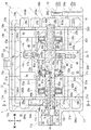
ハウジング1は、フロントハウジング17と、リヤハウジング19と、第1シリンダブロック21と、第2シリンダブロック23と、第1弁形成プレート39と、第2弁形成プレート41とを有している。なお、本実施例では、フロントハウジング17が位置する側を圧縮機の前方側とし、リヤハウジング19が位置する側を圧縮機の後方側として、圧縮機の前後方向を規定している。また、図1及び図2の紙面の上方を圧縮機の上方側とし、紙面の下方を圧縮機の下方側として、圧縮機の上下方向を規定している。そして、図4以降では、図1及び図2に対応させて前後方向及び上下方向を表示する。なお、実施例1における前後方向等は一例であり、本発明の圧縮機は、搭載される車両等に対応して、その姿勢が適宜変更される。   The housing 1 includes a front housing 17, a rear housing 19, a first cylinder block 21, a second cylinder block 23, a first valve forming plate 39, and a second valve forming plate 41. In this embodiment, the front-rear direction of the compressor is defined with the side where the front housing 17 is located as the front side of the compressor and the side where the rear housing 19 is located as the rear side of the compressor. 1 and 2 is defined as the upper side of the compressor, and the lower side of the page is defined as the lower side of the compressor to define the vertical direction of the compressor. In FIG. 4 and subsequent figures, the front-rear direction and the vertical direction are displayed in correspondence with FIGS. In addition, the front-back direction in Example 1 is an example, and the attitude | position of the compressor of this invention is suitably changed according to the vehicle etc. which are mounted.

フロントハウジング17には、前方に向かって突出するボス17aが形成されている他、駆動軸3を挿通させる第1軸孔17bが形成されている。ボス17a内には軸封装置25が設けられている。   The front housing 17 is formed with a boss 17a protruding forward and a first shaft hole 17b through which the drive shaft 3 is inserted. A shaft seal device 25 is provided in the boss 17a.

また、フロントハウジング17内には、第1連通室18aと、第1吸入室27aと、第1吐出室29aと、壁部17cとが形成されている。第1連通室18aは、フロントハウジング17の後端面17dから前方に向かって円柱状に凹設されており、フロントハウジング17の中心側に位置している。   In the front housing 17, a first communication chamber 18a, a first suction chamber 27a, a first discharge chamber 29a, and a wall portion 17c are formed. The first communication chamber 18 a is recessed in a columnar shape from the rear end surface 17 d of the front housing 17 toward the front, and is located on the center side of the front housing 17.

第1吸入室27aは、フロントハウジング17の後端面17dから前方に向かって円環状に凹設されており、図4に示すように、第1連通室18aの外周側に配置されている。第1吐出室29aについても、フロントハウジング17の後端面17dから前方に向かって円環状に凹設されており、第1吸入室27aの外周側に配置されている。壁部17cは第1吸入室27a内に位置しており、上下方向に延びている。壁部17c内には、壁部17cを上下に貫通する絞り通路20が形成されている。この絞り通路20を通じて、第1連通室18aと第1吐出室29aとが連通している。絞り通路20は本発明における絞りの一例である。   The first suction chamber 27a is recessed in an annular shape from the rear end surface 17d of the front housing 17 toward the front, and is disposed on the outer peripheral side of the first communication chamber 18a as shown in FIG. The first discharge chamber 29a is also recessed in an annular shape from the rear end surface 17d of the front housing 17 toward the front, and is disposed on the outer peripheral side of the first suction chamber 27a. The wall portion 17c is located in the first suction chamber 27a and extends in the vertical direction. A throttle passage 20 is formed in the wall portion 17c so as to vertically penetrate the wall portion 17c. Through the throttle passage 20, the first communication chamber 18a and the first discharge chamber 29a communicate with each other. The throttle passage 20 is an example of a throttle in the present invention.

また、図1及び図2に示すように、フロントハウジング17には、第1前方側連通路12aが形成されている。第1前方側連通路12aは、前端が第1吐出室29aに連通しており、後端がフロントハウジング17の後端面17dに開口している。   As shown in FIGS. 1 and 2, the front housing 17 is formed with a first front communication path 12 a. The first front communication passage 12 a has a front end communicating with the first discharge chamber 29 a and a rear end opening on the rear end surface 17 d of the front housing 17.

第2ハウジング19には、第2連通室18b、第2吸入室27b及び第2吐出室29bが形成されている。第2連通室18bは、リヤハウジング19の前端面19aから後方に向かって円柱状に凹設されており、リヤハウジング19の中心側に位置している。なお、上記の第1連通室18a及び第2連通室18bの大きさ等は適宜設計することができる。   In the second housing 19, a second communication chamber 18b, a second suction chamber 27b, and a second discharge chamber 29b are formed. The second communication chamber 18 b is recessed in a columnar shape from the front end surface 19 a of the rear housing 19 to the rear, and is located on the center side of the rear housing 19. The size and the like of the first communication chamber 18a and the second communication chamber 18b can be appropriately designed.

第2吸入室27b及び第2吐出室29bについても、それぞれリヤハウジング19の前端面19aから後方に向かって円環状に凹設されている。第2吸入室27bは、第2連通室18bの外周側に配置されている。第2吐出室29bは、第2吸入室27bの外周側に配置されている。   The second suction chamber 27b and the second discharge chamber 29b are also recessed in an annular shape from the front end surface 19a of the rear housing 19 to the rear. The second suction chamber 27b is disposed on the outer peripheral side of the second communication chamber 18b. The second discharge chamber 29b is disposed on the outer peripheral side of the second suction chamber 27b.

また、リヤハウジング19には、抽気路22及び制御弁24aが設けられている。抽気路22は、第1抽気路22aと第2抽気路22bとで構成されている。第1抽気路22aは、第2吸入室27bと制御弁24aとに接続している。第2抽気路22bは、制御弁24aと第2連通室18bとに接続している。制御弁24aは、第2吸入室27b内の圧力に基づいて自己の開度を変更することにより、抽気路22の開度を変更することが可能となっている。   The rear housing 19 is provided with a bleed passage 22 and a control valve 24a. The bleed passage 22 includes a first bleed passage 22a and a second bleed passage 22b. The first bleed passage 22a is connected to the second suction chamber 27b and the control valve 24a. The second bleed passage 22b is connected to the control valve 24a and the second communication chamber 18b. The control valve 24a can change the opening degree of the extraction passage 22 by changing its own opening degree based on the pressure in the second suction chamber 27b.

さらに、リヤハウジング19には、第1後方側連通路14aが形成されている。この第1後方側連通路14aは、後端が第2吐出室29bに連通しており、前端がリヤハウジング19の前端面19aに開口している。   Further, the rear housing 19 is formed with a first rear communication path 14a. The first rear communication passage 14 a has a rear end communicating with the second discharge chamber 29 b and a front end opening on the front end surface 19 a of the rear housing 19.

第1シリンダブロック21は、フロントハウジング17と第2シリンダブロック23との間に設けられている。第1シリンダブロック21には、駆動軸3の回転軸心O方向に延びる複数個の第1シリンダボア21aが形成されている。各第1シリンダボア21aは、それぞれ周方向に等角度間隔で配置されている。   The first cylinder block 21 is provided between the front housing 17 and the second cylinder block 23. The first cylinder block 21 is formed with a plurality of first cylinder bores 21 a extending in the direction of the rotational axis O of the drive shaft 3. The first cylinder bores 21a are arranged at equiangular intervals in the circumferential direction.

また、第1シリンダブロック21には、駆動軸3を挿通させる第2軸孔21bが形成されている。さらに、第1シリンダブロック21には、第2軸孔21bに圧縮機の後方側から連通する第1凹部21cが形成されている。第1凹部21cは第2軸孔21bと同軸をなしている。第1凹部21cは、第2軸孔21bよりも内径が大きくされている。第1凹部21c内には、第1スラスト軸受35aが設けられている。   The first cylinder block 21 is formed with a second shaft hole 21b through which the drive shaft 3 is inserted. Further, the first cylinder block 21 is formed with a first recess 21c communicating with the second shaft hole 21b from the rear side of the compressor. The first recess 21c is coaxial with the second shaft hole 21b. The first recess 21c has an inner diameter larger than that of the second shaft hole 21b. A first thrust bearing 35a is provided in the first recess 21c.

また、第1シリンダブロック21には、前後方向に延びる第1連絡路37aと第2前方側連通路12bとが形成されている。これらの第1連絡路37a及び第2前方側連通路12bは、それぞれ前端が第1シリンダブロック21の前端面21dに開口しており、後端が第1シリンダブロック21の後端面21eに開口している。   The first cylinder block 21 is formed with a first communication path 37a and a second front side communication path 12b extending in the front-rear direction. Each of the first communication path 37a and the second front communication path 12b has a front end opened to the front end face 21d of the first cylinder block 21 and a rear end opened to the rear end face 21e of the first cylinder block 21. ing.

第2シリンダブロック23は、第1シリンダブロック21とリヤハウジング19との間に設けられている。第2シリンダブロック23は、第1シリンダブロック21に接合されることにより、第1シリンダブロック21との間に斜板室33を形成している。斜板室33は第1凹部21cと連通している。これにより、第1凹部21cは斜板室33の一部を構成している。また、斜板室33は第1連絡路37aと連通している。   The second cylinder block 23 is provided between the first cylinder block 21 and the rear housing 19. The second cylinder block 23 is joined to the first cylinder block 21, thereby forming a swash plate chamber 33 with the first cylinder block 21. The swash plate chamber 33 communicates with the first recess 21c. Thereby, the first recess 21 c constitutes a part of the swash plate chamber 33. The swash plate chamber 33 communicates with the first communication path 37a.

第2シリンダブロック23には、駆動軸3の回転軸心O方向に延びる複数個の第2シリンダボア23aが形成されている。各第2シリンダボア23aは、各第1シリンダボア21aと同様、周方向に等角度間隔でそれぞれ配置されており、各第1シリンダボア21aと同軸かつ前後で対になっている。また、各第1シリンダボア21aと各第2シリンダボア23aとは同径に形成されている。なお、第1シリンダボア21aと第2シリンダボア23aとが対をなしていれば、これらの個数は適宜設計することができる。また、各第1シリンダボア21aと各第2シリンダボア23aとで異なる径の大きさに形成しても良い。さらに、対をなす第1シリンダボア21a及び第2シリンダボア23aの軸心は、ずれていても良い。   The second cylinder block 23 is formed with a plurality of second cylinder bores 23 a extending in the direction of the rotation axis O of the drive shaft 3. Like the first cylinder bores 21a, the second cylinder bores 23a are arranged at equiangular intervals in the circumferential direction, and are coaxially and paired with the first cylinder bores 21a in the front-rear direction. Each first cylinder bore 21a and each second cylinder bore 23a are formed to have the same diameter. In addition, if the 1st cylinder bore 21a and the 2nd cylinder bore 23a have made a pair, these numbers can be designed suitably. Moreover, you may form in the magnitude | size of a different diameter in each 1st cylinder bore 21a and each 2nd cylinder bore 23a. Furthermore, the axial centers of the paired first cylinder bore 21a and second cylinder bore 23a may be shifted.

第2シリンダブロック23には、駆動軸3を挿通させる第3軸孔23bが形成されている。なお、図示を省略しているものの、第1軸孔17b、第2軸孔21b及び第3軸孔23b内には、それぞれ滑り軸受が設けられている。   The second cylinder block 23 is formed with a third shaft hole 23b through which the drive shaft 3 is inserted. Although not shown, sliding bearings are provided in the first shaft hole 17b, the second shaft hole 21b, and the third shaft hole 23b, respectively.

また、第2シリンダブロック23には、第3軸孔23bに圧縮機の前方側から連通する第2凹部23cが形成されている。第2凹部23cは第3軸孔23bと同軸をなしている。第2凹部23cは、第3軸孔23bよりも内径が大きくされている。第2凹部23cも斜板室33と連通しており、斜板室33の一部を構成している。第2凹部23c内には、第2スラスト軸受35bが設けられている。   Further, the second cylinder block 23 is formed with a second recess 23c communicating with the third shaft hole 23b from the front side of the compressor. The second recess 23c is coaxial with the third shaft hole 23b. The second recess 23c has an inner diameter larger than that of the third shaft hole 23b. The second recess 23 c is also in communication with the swash plate chamber 33 and constitutes a part of the swash plate chamber 33. A second thrust bearing 35b is provided in the second recess 23c.

また、第2シリンダブロック23には、吸入ポート330と、第2連絡路37bとが形成されている。斜板室33は、吸入ポート330を介して管路を構成する図示しない蒸発器と接続している。第2連絡路37bは、前後方向に延びており、斜板室33と連通している。   The second cylinder block 23 is formed with a suction port 330 and a second communication path 37b. The swash plate chamber 33 is connected via an intake port 330 to an evaporator (not shown) constituting a pipe line. The second communication path 37 b extends in the front-rear direction and communicates with the swash plate chamber 33.

さらに、第2シリンダブロック23には、吐出ポート230と、合流吐出室231と、第3前方側連通路12cと、第2後方側連通路14bとが形成されている。吐出ポート230と合流吐出室231とは、互いに連通している。合流吐出室231は、吐出ポート230を介して管路を構成する図示しない凝縮器と接続している。   Further, the second cylinder block 23 is formed with a discharge port 230, a merged discharge chamber 231, a third front side communication path 12c, and a second rear side communication path 14b. The discharge port 230 and the merged discharge chamber 231 communicate with each other. The merged discharge chamber 231 is connected to a condenser (not shown) that forms a pipe line via a discharge port 230.

第3前方側連通路12cは、前端が第2シリンダブロック23の前端面23eに開口しており、後端が合流吐出室231に連通している。そして、第3前方側連通路12cは、第1シリンダブロック21と第2シリンダブロック23とが接合されることにより、第2前方側連通路12bと連通する。第2後方側連通路14bは、前端が合流吐出室231に連通しており、後端が第2シリンダブロック23の後端面23dに開口している。   The third front communication path 12c has a front end that opens to the front end surface 23e of the second cylinder block 23, and a rear end that communicates with the merged discharge chamber 231. The third front communication path 12c communicates with the second front communication path 12b by joining the first cylinder block 21 and the second cylinder block 23 together. The second rear communication passage 14 b has a front end communicating with the merged discharge chamber 231 and a rear end opening on the rear end surface 23 d of the second cylinder block 23.

図5に示すように、第1弁形成プレート39は、フロントハウジング17の後端面17dと第1シリンダブロック21の前端面21dとの間に設けられている。この第1弁形成プレート39を介して、フロントハウジング17と第1シリンダブロック21とが接合されている。   As shown in FIG. 5, the first valve forming plate 39 is provided between the rear end surface 17 d of the front housing 17 and the front end surface 21 d of the first cylinder block 21. The front housing 17 and the first cylinder block 21 are joined via the first valve forming plate 39.

第1弁形成プレート39は、バルブプレート390と、吸入弁プレート391と、吐出弁プレート392と、リテーナプレート393とを有している。バルブプレート390、吐出弁プレート392及びリテーナプレート393には、第1シリンダボア21aと同数の第1吸入孔390aが形成されている。バルブプレート390及び吸入弁プレート391には、第1シリンダボア21aと同数の第1吐出孔390bが形成されている。さらに、バルブプレート390、吸入弁プレート391、吐出弁プレート392及びリテーナプレート393には、第1吸入連通孔390cと第1吐出連通孔390dとが形成されている。   The first valve forming plate 39 includes a valve plate 390, a suction valve plate 391, a discharge valve plate 392, and a retainer plate 393. The valve plate 390, the discharge valve plate 392, and the retainer plate 393 are formed with the same number of first suction holes 390a as the first cylinder bores 21a. The valve plate 390 and the intake valve plate 391 are formed with the same number of first discharge holes 390b as the first cylinder bores 21a. Further, the valve plate 390, the suction valve plate 391, the discharge valve plate 392, and the retainer plate 393 are formed with a first suction communication hole 390c and a first discharge communication hole 390d.

各第1シリンダボア21aは、各第1吸入孔390aを通じて第1吸入室27aと連通する。また、各第1シリンダボア21aは、各第1吐出孔390bを通じて第1吐出室29aと連通する。そして、第1吸入連通孔390cを通じて、第1吸入室27aと第1連絡路37aとが連通する。また、第1吐出連通孔390dを通じて、第1前方側連通路12aと第2前方側連通路12bとが連通する。   Each first cylinder bore 21a communicates with the first suction chamber 27a through each first suction hole 390a. Each first cylinder bore 21a communicates with the first discharge chamber 29a through each first discharge hole 390b. The first suction chamber 27a and the first communication path 37a communicate with each other through the first suction communication hole 390c. Further, the first front communication path 12a and the second front communication path 12b communicate with each other through the first discharge communication hole 390d.

吸入弁プレート391は、バルブプレート390の後面に設けられている。吸入弁プレート391には、弾性変形により各第1吸入孔390aを開閉可能な吸入リード弁391aが複数形成されている。吐出弁プレート392は、バルブプレート390の前面に設けられている。吐出弁プレート392には、弾性変形により各第1吐出孔390bを開閉可能な吐出リード弁392aが複数形成されている。リテーナプレート393は、吐出弁プレート392の前面に設けられている。リテーナプレート393は、各吐出リード弁392aの最大開度を規制する。また、第1シリンダブロック21には、各吸入リード弁391aの最大開度を規制するリテーナ21fが凹設されている。なお、説明を容易にするため、図1、図2及び図8では、吸入弁プレート391、吐出弁プレート392、リテーナプレート393及びリテーナ溝21fの図示を省略している。   The suction valve plate 391 is provided on the rear surface of the valve plate 390. The suction valve plate 391 is formed with a plurality of suction reed valves 391a that can open and close the first suction holes 390a by elastic deformation. The discharge valve plate 392 is provided on the front surface of the valve plate 390. The discharge valve plate 392 is formed with a plurality of discharge reed valves 392a that can open and close each first discharge hole 390b by elastic deformation. The retainer plate 393 is provided on the front surface of the discharge valve plate 392. The retainer plate 393 regulates the maximum opening degree of each discharge reed valve 392a. The first cylinder block 21 is recessed with a retainer 21f that regulates the maximum opening of each suction reed valve 391a. For ease of explanation, illustration of the intake valve plate 391, the discharge valve plate 392, the retainer plate 393, and the retainer groove 21f is omitted in FIGS.

図1及び図2に示すように、第2弁形成プレート41は、リヤハウジング19の前端面19aと第2シリンダブロック23の後端面23dとの間に設けられている。この第2弁形成プレート41を介して、リヤハウジング19と第1シリンダブロック23とが接合されている。   As shown in FIGS. 1 and 2, the second valve forming plate 41 is provided between the front end surface 19 a of the rear housing 19 and the rear end surface 23 d of the second cylinder block 23. The rear housing 19 and the first cylinder block 23 are joined via the second valve forming plate 41.

詳細な図示を省略するものの、第2弁形成プレート41は、バルブプレート410を有している他、第1弁形成プレート39と同様に、吸入弁プレート、吐出弁プレート及びリテーナプレートを有している。また、第1シリンダブロック21と同様、第2シリンダブロック23にもリテーナ溝が凹設されている。   Although not shown in detail, the second valve forming plate 41 includes a valve plate 410 and, similarly to the first valve forming plate 39, includes a suction valve plate, a discharge valve plate, and a retainer plate. Yes. Similarly to the first cylinder block 21, the second cylinder block 23 is also provided with a retainer groove.

第2弁形成プレート41には、第2シリンダボア23aと同数の第2吸入孔410aと第2吐出孔410bとが形成されている他、第2吸入連通孔410cと第2吐出連通孔410dとが形成されている。各第2シリンダボア23aは、各第2吸入孔410aを通じて第2吸入室27bと連通する。また、各第2シリンダボア23aは、各第2吐出孔410bを通じて第2吐出室29bと連通する。そして、第2吸入連通孔410cを通じて、第2吸入室27bと第2連絡路37bとが連通する。また、第2吐出連通孔410dを通じて、第1後方側連通路14aと第2後方側連通路14bとが連通する。   The second valve forming plate 41 is formed with the same number of second suction holes 410a and second discharge holes 410b as the second cylinder bores 23a, and has a second suction communication hole 410c and a second discharge communication hole 410d. Is formed. Each second cylinder bore 23a communicates with the second suction chamber 27b through each second suction hole 410a. Each second cylinder bore 23a communicates with the second discharge chamber 29b through each second discharge hole 410b. The second suction chamber 27b and the second communication path 37b communicate with each other through the second suction communication hole 410c. Further, the first rear communication path 14a and the second rear communication path 14b communicate with each other through the second discharge communication hole 410d.

この圧縮機では、第1、2連絡路37a、37b及び第1、2吸入連通孔390c、410cにより、第1、2吸入室27a、27bと斜板室33とが互いに連通している。このため、第1、2吸入室27a、27b内と斜板室33内とは、圧力がほぼ等しくなっている。そして、斜板室33には、吸入ポート330を通じて蒸発器を経た低圧の冷媒ガスが流入することから、斜板室33内及び第1、2吸入室27a、27b内は、第1、2吐出室29a、29b内よりも低圧である。   In this compressor, the first and second suction chambers 27a and 27b and the swash plate chamber 33 communicate with each other through the first and second communication paths 37a and 37b and the first and second suction communication holes 390c and 410c. Therefore, the pressures in the first and second suction chambers 27a and 27b and the swash plate chamber 33 are substantially equal. Since the low-pressure refrigerant gas that has passed through the evaporator flows into the swash plate chamber 33 through the suction port 330, the first and second discharge chambers 29a are provided in the swash plate chamber 33 and the first and second suction chambers 27a and 27b. , 29b.

また、この圧縮機では、第1前方側連通路12a、第1吐出連通孔390d、第2前方側連通路12b及び第3前方側連通路12cによって、第1吐出連通路12が形成されている。さらに、第1後方側連通路14a、第2吐出連通孔410d及び第2後方側連通路14bによって、第2吐出連通路14が形成されている。そして、第1吐出室29aと第2吐出室29bとは、第1吐出連通路12、第2吐出連通路14及び合流吐出室231を通じて、互いに連通している。   In this compressor, the first discharge communication passage 12 is formed by the first front communication passage 12a, the first discharge communication hole 390d, the second front communication passage 12b, and the third front communication passage 12c. . Further, a second discharge communication path 14 is formed by the first rear communication path 14a, the second discharge communication hole 410d, and the second rear communication path 14b. The first discharge chamber 29a and the second discharge chamber 29b communicate with each other through the first discharge communication path 12, the second discharge communication path 14, and the merged discharge chamber 231.

駆動軸3は、駆動軸本体30と第1支持部材43aと第2支持部材43bとで構成されている。また、駆動軸3の前端には、ねじ部3aが形成されている。このねじ部3aを介して駆動軸3は、図示しないプーリ又は電磁クラッチと連結されている。また、駆動軸3には、制御路55が形成されている。なお、制御路55の詳細は後述する。   The drive shaft 3 includes a drive shaft main body 30, a first support member 43a, and a second support member 43b. A screw portion 3 a is formed at the front end of the drive shaft 3. The drive shaft 3 is connected to a pulley or an electromagnetic clutch (not shown) via the screw portion 3a. A control path 55 is formed on the drive shaft 3. Details of the control path 55 will be described later.

駆動軸本体30は、軸方向でハウジング1の前方側から後方側に向かって延びている。駆動軸本体30の前方側には、第1小径部30aが形成されている。駆動軸本体30の後方側には、第2小径部30bが形成されている。   The drive shaft main body 30 extends from the front side of the housing 1 toward the rear side in the axial direction. A first small diameter portion 30 a is formed on the front side of the drive shaft main body 30. A second small diameter portion 30 b is formed on the rear side of the drive shaft main body 30.

また、駆動軸本体30には、上記の斜板5とリンク機構7とアクチュエータ13とが設けられている。これらの斜板5とリンク機構7とアクチュエータ13とは、それぞれ斜板室33内に配置されている。   The drive shaft body 30 is provided with the swash plate 5, the link mechanism 7, and the actuator 13. The swash plate 5, the link mechanism 7, and the actuator 13 are respectively disposed in the swash plate chamber 33.

第1支持部材43aは、駆動軸3の回転軸心Oを中心軸とする円筒状に形成されている。第1支持部材43aは、駆動軸本体30の第1小径部30aに圧入されている。第1支持部材43aの後端には、第1フランジ430が形成されている。また、図5に示すように、第1支持部材43aの外周面には、第1環状溝431と第2環状溝432とが形成されている。第1環状溝431内には、第1封止部材44aが設けられている。第2環状溝432内には、第2封止部材44bが設けられている。   The first support member 43 a is formed in a cylindrical shape with the rotation axis O of the drive shaft 3 as the central axis. The first support member 43 a is press-fitted into the first small diameter portion 30 a of the drive shaft main body 30. A first flange 430 is formed at the rear end of the first support member 43a. As shown in FIG. 5, a first annular groove 431 and a second annular groove 432 are formed on the outer peripheral surface of the first support member 43a. A first sealing member 44 a is provided in the first annular groove 431. A second sealing member 44 b is provided in the second annular groove 432.

図1及び図2に示すように、第2支持部材43bについても、駆動軸3の回転軸心Oを中心軸とする円筒状に形成されている。第2支持部材43bは、駆動軸本体30の第2小径部30bの後端側に圧入されている。第2支持部材43bには、第2フランジ433が形成されている他、後述する第2ピン47bが挿通される取付部(図示略)が形成されている。   As shown in FIGS. 1 and 2, the second support member 43 b is also formed in a cylindrical shape with the rotation axis O of the drive shaft 3 as the central axis. The second support member 43 b is press-fitted to the rear end side of the second small diameter portion 30 b of the drive shaft main body 30. The second support member 43b is provided with a second flange 433 and an attachment portion (not shown) through which a second pin 47b described later is inserted.

駆動軸3は、ハウジング1内において、軸封装置25、第1、2連通室18a、18b、第1〜3軸孔17b、21b、23b、第1、2弁形成プレート39、41、斜板室33及び第1、2スラスト軸受35a、35bに挿通されている。これにより、図5に示すように、駆動軸3では、第1支持部材43aが軸封装置25、第1連通室18a、第1弁形成プレート39及び第1スラスト軸受35aに挿通されつつ、第1、2軸孔17b、21bに支持されている。また、第1封止部材44aは第1軸孔17b内に配置され、第2封止部材44bは第2軸孔21b内に配置される。これにより、第1、2封止部材44a、44bは、第1連通室18a内の冷媒ガスが斜板室33等の第1連通室18aの外部へ漏れることを防止する。   In the housing 1, the drive shaft 3 includes a shaft sealing device 25, first and second communication chambers 18a and 18b, first to third shaft holes 17b, 21b and 23b, first and second valve forming plates 39 and 41, and a swash plate chamber. 33 and first and second thrust bearings 35a and 35b. As a result, as shown in FIG. 5, in the drive shaft 3, the first support member 43a is inserted into the shaft seal device 25, the first communication chamber 18a, the first valve forming plate 39, and the first thrust bearing 35a. It is supported by the 1 and 2 shaft holes 17b and 21b. The first sealing member 44a is disposed in the first shaft hole 17b, and the second sealing member 44b is disposed in the second shaft hole 21b. Thus, the first and second sealing members 44a and 44b prevent the refrigerant gas in the first communication chamber 18a from leaking outside the first communication chamber 18a such as the swash plate chamber 33.

一方、図1及び図2に示すように、第2支持部材43aは第2スラスト軸受35b及び第2弁形成プレート41に挿通されつつ、第3軸孔23bに支持されている。駆動軸3の後端は、第2連通室18b内に突出している。こうして、駆動軸3はハウジング1に支承されており、圧縮機の前後方向と平行な回転軸心O周りで回転可能となっている。また、駆動軸3がハウジング1に支承されることにより、第1フランジ430は、第1凹部21cの前壁との間で、第1スラスト軸受35aを軸方向から挟持する。第2フランジ433は、第2凹部23cの後壁との間で、第2スラスト軸受35bを軸方向から挟持する。なお、図示を省略するものの、第2支持部材43bと第3軸受23bとの間には、第2連通室18bと斜板室33との間を封止する封止部材が設けられている。   On the other hand, as shown in FIGS. 1 and 2, the second support member 43a is supported by the third shaft hole 23b while being inserted through the second thrust bearing 35b and the second valve forming plate 41. The rear end of the drive shaft 3 protrudes into the second communication chamber 18b. Thus, the drive shaft 3 is supported by the housing 1 and can rotate around the rotation axis O parallel to the front-rear direction of the compressor. In addition, when the drive shaft 3 is supported by the housing 1, the first flange 430 sandwiches the first thrust bearing 35a from the axial direction between the first flange 430 and the front wall of the first recess 21c. The second flange 433 sandwiches the second thrust bearing 35b from the axial direction between the second flange 433 and the rear wall of the second recess 23c. Although not shown, a sealing member that seals between the second communication chamber 18b and the swash plate chamber 33 is provided between the second support member 43b and the third bearing 23b.

斜板5は環状の平板形状をなしており、前面5aと後面5bとを有している。前面5aは、斜板室33内において圧縮機の前方側、つまり、フロントハウジング17側に面している。後面5bは、斜板室33内において圧縮機の後方側、つまり、リヤハウジング19側に面している。   The swash plate 5 has an annular flat plate shape and has a front surface 5a and a rear surface 5b. The front surface 5 a faces the front side of the compressor in the swash plate chamber 33, that is, the front housing 17 side. The rear surface 5 b faces the rear side of the compressor in the swash plate chamber 33, that is, the rear housing 19 side.

斜板5はリングプレート45を有している。このリングプレート45は環状の平板形状に形成されており、中心部に挿通孔45aが形成されている。斜板5は、斜板室33内において挿通孔45aに駆動軸本体30が挿通されることにより、駆動軸3に取り付けられている。また、リングプレート45には、斜板5の前面5a側から後面5b側まで貫通する溝部45bが形成されている。また、リングプレート45と、第2支持部材43bの第2フランジ433との間には、駆動軸3周りで復帰ばね(図示略)が設けられている。   The swash plate 5 has a ring plate 45. The ring plate 45 is formed in an annular flat plate shape, and an insertion hole 45a is formed at the center. The swash plate 5 is attached to the drive shaft 3 by inserting the drive shaft main body 30 through the insertion hole 45 a in the swash plate chamber 33. Further, the ring plate 45 is formed with a groove portion 45b penetrating from the front surface 5a side to the rear surface 5b side of the swash plate 5. A return spring (not shown) is provided around the drive shaft 3 between the ring plate 45 and the second flange 433 of the second support member 43b.

リンク機構7はラグアーム49を有している。ラグアーム49は、斜板室33内において、斜板5よりも後方に配置されており、斜板5と第2支持部材43bとの間に位置している。ラグアーム49は、前方から後方に向かって略L字形状となるように形成されている。また、ラグアーム49には、ウェイト部49aが形成されている。なお、ウェイト部49aの形状は適宜設計することが可能である。   The link mechanism 7 has a lug arm 49. The lug arm 49 is disposed behind the swash plate 5 in the swash plate chamber 33, and is located between the swash plate 5 and the second support member 43b. The lug arm 49 is formed so as to be substantially L-shaped from the front to the rear. The lug arm 49 has a weight portion 49a. The shape of the weight portion 49a can be designed as appropriate.

ラグアーム49の前端側は、第1ピン47aによってリングプレート45と連結されている。これにより、ラグアーム49は、第1ピン47aの軸心を第1揺動軸心M1として、リングプレート45、すなわち斜板5に対し、第1揺動軸心M1周りで揺動可能に支持されている。   The front end side of the lug arm 49 is connected to the ring plate 45 by the first pin 47a. Thereby, the lug arm 49 is supported by the ring plate 45, that is, the swash plate 5 so as to be swingable around the first swing axis M1 with the first pin 47a as the first swing axis M1. ing.

ラグアーム49の後端側は、第2ピン47bによって第2支持部材43bと連結されている。これにより、ラグアーム49は、第2ピン47bの軸心を第2揺動軸心M2として、第2支持部材43b、すなわち駆動軸3に対し、第2揺動軸心M2周りで揺動可能に支持されている。これらのラグアーム49、第1、2ピン47a、47bに加えて、後述する連結アーム132及び第3ピン47cによって、本発明におけるリンク機構7が構成されている。   The rear end side of the lug arm 49 is connected to the second support member 43b by the second pin 47b. As a result, the lug arm 49 can swing around the second swing axis M2 with respect to the second support member 43b, that is, the drive shaft 3, with the second pivot 47b serving as the second pivot axis M2. It is supported. In addition to the lug arm 49 and the first and second pins 47a and 47b, the link arm 7 and the third pin 47c, which will be described later, constitute the link mechanism 7 in the present invention.

ウェイト部49aは、ラグアーム49の前端側、つまり、第1揺動軸心M1を基準として第2揺動軸心M2とは反対側に延在して設けられている。このため、ラグアーム49が第1ピン47aによってリングプレート45に支持されることで、ウェイト部49aはリングプレート45の溝部45bを通って、リングプレート45の前面、つまり斜板5の前面5a側に位置する。そして、斜板5が回転軸心O周りに回転することにより発生する遠心力が斜板5の前面5a側でウェイト部49aにも作用する。   The weight portion 49a is provided to extend to the front end side of the lug arm 49, that is, on the opposite side of the second swing axis M2 with respect to the first swing axis M1. For this reason, the lug arm 49 is supported by the ring plate 45 by the first pin 47 a, so that the weight portion 49 a passes through the groove portion 45 b of the ring plate 45 and faces the front surface of the ring plate 45, ie, the front surface 5 a side of the swash plate 5. To position. Then, the centrifugal force generated when the swash plate 5 rotates around the rotation axis O also acts on the weight portion 49a on the front surface 5a side of the swash plate 5.

この圧縮機では、斜板5と駆動軸3とがリンク機構7によって連結されることにより、斜板5は駆動軸3と共に回転することが可能となっている。また、ラグアーム49の両端がそれぞれ第1揺動軸心M1及び第2揺動軸心M2周りで揺動することにより、斜板5は、図1に示す最小値から図2に示す最大値まで傾斜角度を変更することが可能となっている。   In this compressor, the swash plate 5 and the drive shaft 3 are connected by the link mechanism 7 so that the swash plate 5 can rotate together with the drive shaft 3. Further, the both ends of the lug arm 49 swing around the first swing axis M1 and the second swing axis M2, respectively, so that the swash plate 5 moves from the minimum value shown in FIG. 1 to the maximum value shown in FIG. The inclination angle can be changed.

図1及び図2に示すように、各ピストン9は、それぞれ前端に第1頭部9aを有しており、後端に第2頭部9bを有している。つまり、各ピストン9は両頭ピストンである。各第1頭部9aは、それぞれ各第1シリンダボア21a内を往復動可能に収納されている。これらの各第1頭部9aと第1弁形成プレート39とにより、第1シリンダボア21a内にそれぞれ第1圧縮室53aが形成されている。各第2頭部9bは、それぞれ第2シリンダボア23a内を往復動可能に収納されている。これらの各第2頭部9bと第2弁形成プレート41とにより、第2シリンダボア23a内にそれぞれ第2圧縮室53bが形成されている。   As shown in FIG.1 and FIG.2, each piston 9 has the 1st head 9a in the front end, respectively, and has the 2nd head 9b in the rear end. That is, each piston 9 is a double-headed piston. Each first head portion 9a is accommodated in each first cylinder bore 21a so as to reciprocate. The first compression chambers 53a are formed in the first cylinder bore 21a by the first heads 9a and the first valve forming plate 39, respectively. Each of the second heads 9b is housed so as to reciprocate within the second cylinder bore 23a. The second compression chambers 53b are formed in the second cylinder bores 23a by the second heads 9b and the second valve forming plate 41, respectively.

また、各ピストン9の中央には係合部9cが形成されている。各係合部9c内には、半球状のシュー11a、11bがそれぞれ設けられている。これらのシュー11a、11bは、変換機構として斜板5の回転をピストン9の往復動に変換する。こうして、斜板5の傾斜角度に応じたストロークで、各第1頭部9aがそれぞれ第1シリンダボア21a内を往復動することが可能となっているとともに、各第2頭部9bがそれぞれ第2シリンダボア23a内を往復動することが可能となっている。   In addition, an engaging portion 9 c is formed at the center of each piston 9. In each engaging portion 9c, hemispherical shoes 11a and 11b are provided. These shoes 11 a and 11 b convert the rotation of the swash plate 5 into the reciprocating motion of the piston 9 as a conversion mechanism. Thus, the first heads 9a can reciprocate in the first cylinder bores 21a with a stroke corresponding to the inclination angle of the swash plate 5, and the second heads 9b are secondly moved. It is possible to reciprocate within the cylinder bore 23a.

ここで、この圧縮機では、斜板5の傾斜角度の変更に伴い各ピストン9のストロークが変化することで、リンク機構7は、各第1頭部9aと各第2頭部9bとの各上死点位置を移動させる。具体的には、図1に示すように、リンク機構7は、斜板5の傾斜角度が小さくなるに伴って、各第2頭部9bの上死点位置よりも各第1頭部9aの上死点位置を大きく移動させる。   Here, in this compressor, the stroke of each piston 9 changes with the change of the inclination angle of the swash plate 5, so that the link mechanism 7 is connected to each of the first head 9 a and each second head 9 b. Move the top dead center position. Specifically, as shown in FIG. 1, as the inclination angle of the swash plate 5 becomes smaller, the link mechanism 7 moves each first head 9 a than the top dead center position of each second head 9 b. Move the top dead center position greatly.

アクチュエータ13は、斜板室33内において斜板5よりも前方側に配置されている。より具体的には、アクチュエータ13は、斜板室33内において、斜板5を基準として第1シリンダブロック21側に位置している。これにより、アクチュエータ13は、第1凹部21c内に進入することが可能となっている。   The actuator 13 is disposed in front of the swash plate 5 in the swash plate chamber 33. More specifically, the actuator 13 is located on the first cylinder block 21 side in the swash plate chamber 33 with respect to the swash plate 5. Thereby, the actuator 13 can enter the first recess 21c.

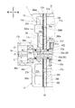
図6に示すように、アクチュエータ13は、移動体13aと区画体13bと制御圧室13cとを有している。制御圧室13cは、移動体13aと区画体13bとの間に形成されている。   As shown in FIG. 6, the actuator 13 includes a moving body 13a, a partitioning body 13b, and a control pressure chamber 13c. The control pressure chamber 13c is formed between the movable body 13a and the partition body 13b.

移動体13aは、前壁130と、周壁131と、一対の連結アーム132とを有している。なお、図1、図2、図6及び図8では、連結アーム132の一方のみを図示している。   The moving body 13a includes a front wall 130, a peripheral wall 131, and a pair of connecting arms 132. 1, 2, 6, and 8, only one of the connecting arms 132 is shown.

図6に示すように、前壁130は移動体13aの前方に位置しており、回転軸心Oから離れる方向で径方向に延びている。また、前壁130には挿通孔130aが貫設されている。挿通孔130a内にはOリング51aが設けられている。周壁131は、前壁130の外周縁と連続し、移動体13aの後方に向かって延びている。これらの前壁130及び周壁131により、移動体13aは有底の円筒状をなしている。各連結アーム132は周壁131の後端にそれぞれ形成されており、周壁131から圧縮機の後方に向かって延びている。各連結アーム132には、後述する第3ピン47cを挿通する挿通孔132aが形成されている。   As shown in FIG. 6, the front wall 130 is located in front of the moving body 13 a and extends in the radial direction in a direction away from the rotation axis O. Further, an insertion hole 130a is provided in the front wall 130. An O-ring 51a is provided in the insertion hole 130a. The peripheral wall 131 is continuous with the outer peripheral edge of the front wall 130 and extends toward the rear of the movable body 13a. Due to the front wall 130 and the peripheral wall 131, the movable body 13a has a bottomed cylindrical shape. Each connecting arm 132 is formed at the rear end of the peripheral wall 131 and extends from the peripheral wall 131 toward the rear of the compressor. Each connecting arm 132 is formed with an insertion hole 132a through which a third pin 47c described later is inserted.

区画体13bは、移動体13aの内径とほぼ同径をなす略円板状に形成されている。区画体13bは中心に挿通孔133が貫設されている。また、区画体13bの外周にはOリング51bが設けられている。さらに、区画体13bには前方から後方に向かって凹む凹面134が形成されている。   The partition body 13b is formed in a substantially disc shape having substantially the same diameter as the inner diameter of the moving body 13a. The partition 13b has an insertion hole 133 extending through the center. An O-ring 51b is provided on the outer periphery of the partition 13b. Further, the partition 13b is formed with a concave surface 134 that is recessed from the front to the rear.

移動体13aの挿通孔130aには、駆動軸本体30が挿通されている。これにより、移動体13aは、駆動軸本体30を回転軸心O方向に移動することが可能となっている。一方、区画体13bの挿通孔133に対して、駆動軸本体30が圧入されている。これにより、区画体13bは駆動軸本体30に固定され、区画体13bは駆動軸本体30と共に回転可能となっている。なお、区画体13bについても回転軸心O方向に移動可能に駆動軸本体30に挿通する構成としても良い。   The drive shaft main body 30 is inserted through the insertion hole 130a of the moving body 13a. Thereby, the moving body 13a can move the drive shaft main body 30 in the direction of the rotation axis O. On the other hand, the drive shaft main body 30 is press-fitted into the insertion hole 133 of the partition 13b. As a result, the partition body 13 b is fixed to the drive shaft main body 30, and the partition body 13 b can rotate together with the drive shaft main body 30. The partition 13b may also be configured to be inserted through the drive shaft main body 30 so as to be movable in the direction of the rotation axis O.

区画体13bは、移動体13a内に配置されており、その周囲が周壁131によって取り囲まれた状態となっている。これにより、移動体13aが回転軸心O方向に移動するに当たり、周壁131の内周面と、区画体13bの外周面とが摺動する。   The partition body 13b is disposed in the moving body 13a and is surrounded by the peripheral wall 131. Thereby, when the moving body 13a moves in the rotation axis O direction, the inner peripheral surface of the peripheral wall 131 and the outer peripheral surface of the partition 13b slide.

そして、区画体13bが周壁131によって取り囲まれることにより、移動体13aと区画体13bとの間に制御圧室13cが形成されている。この制御圧室13cは、前壁130と周壁131と区画体13bとによって斜板室33から区画されている。   And the control body 13c is formed between the mobile body 13a and the division body 13b because the division body 13b is surrounded by the surrounding wall 131. FIG. The control pressure chamber 13c is partitioned from the swash plate chamber 33 by the front wall 130, the peripheral wall 131, and the partition body 13b.

図1及び図2に示すように、各牽引アーム132と、リングプレート45とは、第3ピン47cによって連結されている。これにより、斜板5は、第3ピン47cの軸心を第3軸心M3として、第3軸心M3周りで移動体13aに揺動可能に連結されている。ここで、第1ピン47aと第3ピン47cとは、駆動軸本体30を挟んで対向して配置されている。つまり、各牽引アーム132は、回転軸心Oを基準として、溝部45bとは反対側でリングプレート45に連結されている。また、区画体13bとリングプレート45との間には、駆動軸3周りで傾角減少ばね(図示略)が設けられている。   As shown in FIGS. 1 and 2, each pulling arm 132 and the ring plate 45 are connected by a third pin 47c. As a result, the swash plate 5 is pivotally connected to the moving body 13a around the third axis M3 with the third pin 47c as the third axis M3. Here, the first pin 47a and the third pin 47c are arranged to face each other with the drive shaft body 30 in between. That is, each traction arm 132 is connected to the ring plate 45 on the side opposite to the groove 45b with the rotation axis O as a reference. In addition, an inclination-decreasing spring (not shown) is provided around the drive shaft 3 between the partition 13b and the ring plate 45.

制御路55は、第1、2軸路55a、55bと第1、2径路55c、55dとで構成されている。第1軸路55aは、駆動軸本体30の内部に形成されており、駆動軸本体30の軸方向で、駆動軸本体30の前後方向の略中央から駆動軸本体30の前端側まで延びている。第2軸路55bも駆動軸本体30に形成されている。第2軸路55bは、第1軸路55aよりも大径に形成されており、駆動軸本体30の後端面に開口している。第2軸路55bは、第1軸路55aと同軸で駆動軸本体30の後端面から駆動軸本体30の前後方向の略中央まで延びており、第1軸路55aに接続している。図6に示すように、第2軸路55b内には隔壁部材57が設けられている。隔壁部材57は、第2軸路55bの前端、すなわち、第1軸路55aと第2軸路55bとの間に配置されている。隔壁部材57は本発明における隔壁の一例である。なお、隔壁部材57を省略し、第1軸路55aと第2軸路55bとを同径に形成しても良い。   The control path 55 includes first and second axial paths 55a and 55b and first and second radial paths 55c and 55d. The first axial path 55 a is formed inside the drive shaft main body 30, and extends from the approximate center of the drive shaft main body 30 in the front-rear direction to the front end side of the drive shaft main body 30 in the axial direction of the drive shaft main body 30. . The second axial path 55 b is also formed in the drive shaft main body 30. The second axial path 55 b is formed to have a larger diameter than the first axial path 55 a and opens on the rear end surface of the drive shaft main body 30. The second axial path 55b is coaxial with the first axial path 55a and extends from the rear end surface of the drive shaft main body 30 to the approximate center in the front-rear direction of the drive shaft main body 30 and is connected to the first axial path 55a. As shown in FIG. 6, a partition wall member 57 is provided in the second axial path 55b. The partition member 57 is disposed at the front end of the second axis 55b, that is, between the first axis 55a and the second axis 55b. The partition member 57 is an example of a partition wall in the present invention. The partition member 57 may be omitted, and the first axial path 55a and the second axial path 55b may be formed to have the same diameter.

第1径路55cは、駆動軸本体30の前後方向の略中央に形成されている。第1径路55cは、第1軸路55aの後端側と接続しつつ駆動軸本体30の径方向に延びており、駆動軸本体30の外周面に開口している。第2径路55dは、駆動軸本体30の前後方向の略中央であって、第1径路55cよりも後方に形成されている。第2径路55dは、第2軸路55bの前端側と接続しつつ駆動軸本体30の径方向に延びており、駆動軸本体30の外周面に開口している。上記のように駆動軸3にアクチュエータ13が設けられることにより、第1径路55cは、第1軸路55aと制御圧室13cとを連通している。また、第2径路55dは、第2軸路55bと制御圧室13cとを連通している。   The first path 55 c is formed at the approximate center in the front-rear direction of the drive shaft body 30. The first path 55 c extends in the radial direction of the drive shaft body 30 while being connected to the rear end side of the first axis 55 a, and is open to the outer peripheral surface of the drive shaft body 30. The second path 55d is substantially in the center in the front-rear direction of the drive shaft main body 30, and is formed behind the first path 55c. The second path 55 d extends in the radial direction of the drive shaft body 30 while being connected to the front end side of the second axis 55 b, and is open to the outer peripheral surface of the drive shaft body 30. By providing the actuator 13 on the drive shaft 3 as described above, the first path 55c communicates the first axis 55a and the control pressure chamber 13c. The second path 55d communicates the second axial path 55b and the control pressure chamber 13c.

また、図5に示すように、駆動軸3には、第3径路55eが形成されている。第3径路55eは、駆動軸3の前端側に形成されている。第3径路55eは、第1軸路55aの前端側と接続しつつ駆動軸本体30及び第1支持部材43aの径方向に延びており、第1支持部材43aの外周面に開口している。第3径路55eは、上記のように駆動軸3がハウジング1に支承されることにより、第1連通室18a内に位置して、第1連通室18aと第1軸路55aとを連通している。   As shown in FIG. 5, the drive shaft 3 is formed with a third path 55 e. The third path 55 e is formed on the front end side of the drive shaft 3. The third path 55e extends in the radial direction of the drive shaft main body 30 and the first support member 43a while being connected to the front end side of the first axis 55a, and opens on the outer peripheral surface of the first support member 43a. The third path 55e is located in the first communication chamber 18a by connecting the drive shaft 3 to the housing 1 as described above, and communicates the first communication chamber 18a and the first axis 55a. Yes.

図1及び図2に示すように、この圧縮機では、第3径路55e、第1連通室18a及び絞り通路20によって、第1軸路55a及び第1径路55cが第1吐出室29aと連通している。また、第2連通室18b、抽気路22及び制御弁24aによって、第2軸路55b及び第2径路55dが第2吸入室27bと連通している。つまり、この圧縮機では、第3径路55e、第1連通室18a及び絞り通路20によって、制御路55を第1吐出室29aに連通させる第1通路59aが構成されている。また、第2連通室18b、抽気路22及び制御弁24aによって、制御路55を第2吸入室27bに連通させる第2通路59bが構成されている。   As shown in FIGS. 1 and 2, in this compressor, the first axial path 55a and the first radial path 55c communicate with the first discharge chamber 29a by the third radial path 55e, the first communication chamber 18a, and the throttle path 20. ing. Further, the second communication passage 18b, the extraction passage 22, and the control valve 24a communicate the second axial passage 55b and the second passage 55d with the second suction chamber 27b. In other words, in this compressor, the third passage 55e, the first communication chamber 18a, and the throttle passage 20 constitute a first passage 59a that communicates the control passage 55 with the first discharge chamber 29a. Further, the second communication chamber 18b, the bleed passage 22 and the control valve 24a constitute a second passage 59b for communicating the control passage 55 with the second suction chamber 27b.

そして、図6に示すように、この圧縮機では、制御路55のうち、第1軸路55a及び第1径路55cによって、第1吐出室29a内の冷媒ガスが制御圧室13c内へ至る給気経路61aが構成されている。また、制御路55のうち、第2軸路55b及び第2径路55dによって、制御圧室13c内の冷媒ガスが第2吸入室27b内へ至る抽気経路61bが構成されている。これらの給気経路61aと抽気経路61bとは、上記の隔壁部材57によって隔てられている。   As shown in FIG. 6, in this compressor, the refrigerant gas in the first discharge chamber 29 a is supplied to the control pressure chamber 13 c by the first axial path 55 a and the first radial path 55 c in the control path 55. An air path 61a is configured. Of the control path 55, the second axial path 55b and the second path 55d constitute an extraction path 61b through which the refrigerant gas in the control pressure chamber 13c reaches the second suction chamber 27b. The air supply path 61a and the extraction path 61b are separated by the partition member 57 described above.

図3に示すように、制御機構15は、制御路55と、第1通路59aと、第2通路59bとを有している。制御機構15は、第1通路59a及び制御路55を流通させて、第1吐出室29a内の冷媒ガスを制御圧室13c内に導入するとともに、制御路55及び第2通路59bを流通させて、制御圧室13c内の冷媒ガスを第2吸入室27b内へ導出する。具体的には、制御機構15は、絞り通路20、第1連通室18a、第3径路55e、第1軸路55a及び第1径路55cを流通させて、第1吐出室29a内の冷媒ガスを制御圧室13c内に導入する。そして、第2径路55d、第2軸路55b、第2連通室18b及び抽気路22を流通させて、制御圧室13c内の冷媒ガスを第2吸入室27b内へ導出する。この際、絞り通路20は第1通路59aの開度を絞り、制御弁24aは第2通路59bの開度を変更する。こうして、制御機構15は、制御圧室13c内の圧力を制御する。なお、制御機構15による制御圧室13c内の圧力制御の詳細は後述する。   As shown in FIG. 3, the control mechanism 15 includes a control path 55, a first passage 59a, and a second passage 59b. The control mechanism 15 circulates the first passage 59a and the control passage 55 to introduce the refrigerant gas in the first discharge chamber 29a into the control pressure chamber 13c, and circulates the control passage 55 and the second passage 59b. Then, the refrigerant gas in the control pressure chamber 13c is led out into the second suction chamber 27b. Specifically, the control mechanism 15 causes the refrigerant gas in the first discharge chamber 29a to flow through the throttle passage 20, the first communication chamber 18a, the third passage 55e, the first axial passage 55a, and the first passage 55c. It introduce | transduces in the control pressure chamber 13c. Then, the refrigerant gas in the control pressure chamber 13c is led into the second suction chamber 27b through the second path 55d, the second axial path 55b, the second communication chamber 18b, and the extraction passage 22. At this time, the throttle passage 20 throttles the opening of the first passage 59a, and the control valve 24a changes the opening of the second passage 59b. Thus, the control mechanism 15 controls the pressure in the control pressure chamber 13c. Details of the pressure control in the control pressure chamber 13c by the control mechanism 15 will be described later.

この圧縮機では、図1及び図2に示す吸入ポート330に対して蒸発器に繋がる配管が接続されるとともに、吐出ポート230に対して凝縮器に繋がる配管が接続される。凝縮器は配管及び膨張弁を介して蒸発器と接続される。これらの圧縮機、蒸発器、膨張弁、凝縮器等によって車両用空調装置の冷凍回路が構成されている。なお、蒸発器、膨張弁、凝縮器及び各配管の図示は省略する。   In this compressor, a pipe connected to the evaporator is connected to the suction port 330 shown in FIGS. 1 and 2, and a pipe connected to the condenser is connected to the discharge port 230. The condenser is connected to the evaporator via a pipe and an expansion valve. These compressors, evaporators, expansion valves, condensers and the like constitute a refrigeration circuit for a vehicle air conditioner. In addition, illustration of an evaporator, an expansion valve, a condenser, and each piping is abbreviate | omitted.

以上のように構成された圧縮機では、駆動軸3が回転することにより、斜板5が回転する。これにより、各ピストン9では、各第1頭部9aが各第1シリンダボア21a内を往復動し、各第2頭部9bが各第2シリンダボア23a内を往復動する。このため、第1、2圧縮室53a、53bがピストン9のストロークに応じて容積変化を生じる。このため、この圧縮機では、第1、2吸入室27a、27bから第1、2圧縮室53a、53bへ冷媒ガスを吸入する吸入行程と、第1、2圧縮室53a、53bにおいて冷媒ガスが圧縮される圧縮行程と、圧縮された冷媒ガスが第1、2吐出室29a、29bに吐出される吐出行程等とが繰り返し行われることとなる。第1吐出室29aに吐出された冷媒ガスは、第1吐出連通路12を経て合流吐出室231に至る。同様に、第2吐出室29bに吐出された冷媒ガスは、第2吐出連通路14を経て合流吐出室231に至る。そして、合流吐出室231に至った冷媒ガスは、吐出ポート230から配管を介して凝縮器に吐出される。   In the compressor configured as described above, the swash plate 5 rotates as the drive shaft 3 rotates. Thereby, in each piston 9, each 1st head 9a reciprocates within each 1st cylinder bore 21a, and each 2nd head 9b reciprocates within each 2nd cylinder bore 23a. For this reason, the first and second compression chambers 53 a and 53 b change in volume according to the stroke of the piston 9. For this reason, in this compressor, the suction process of sucking the refrigerant gas from the first and second suction chambers 27a and 27b to the first and second compression chambers 53a and 53b, and the refrigerant gas in the first and second compression chambers 53a and 53b. The compression stroke to be compressed and the discharge stroke in which the compressed refrigerant gas is discharged into the first and second discharge chambers 29a and 29b are repeatedly performed. The refrigerant gas discharged into the first discharge chamber 29 a reaches the merged discharge chamber 231 through the first discharge communication path 12. Similarly, the refrigerant gas discharged into the second discharge chamber 29 b reaches the merged discharge chamber 231 through the second discharge communication path 14. Then, the refrigerant gas reaching the merged discharge chamber 231 is discharged from the discharge port 230 to the condenser via the pipe.

そして、これらの吸入行程等が行われる間、斜板5、リングプレート45、ラグアーム49及び第1ピン47aからなる回転体には斜板5の傾斜角度を小さくするピストン圧縮力が作用する。そして、斜板5の傾斜角度が変更されれば、ピストン9のストロークの増減による容量制御を行うことが可能である。   During these suction strokes and the like, a piston compression force that reduces the inclination angle of the swash plate 5 acts on the rotating body including the swash plate 5, the ring plate 45, the lug arm 49, and the first pin 47a. If the inclination angle of the swash plate 5 is changed, it is possible to perform capacity control by increasing or decreasing the stroke of the piston 9.

具体的には、制御機構15は、第1通路59a及び給気経路61a、すなわち、絞り通路20、第1連通室18a、第3径路55e、第1軸路55a及び第1径路55cを流通させて、第1吐出室29a内の冷媒ガスを制御圧室13c内に導入する。この際、絞り通路20によって、第1吐出室29a内から制御圧室13c内へ導入される冷媒ガスの流量が調整されることで、第1吐出室29a内から制御圧室13c内に導入される冷媒ガスの圧力が調整される。また、制御機構15は、抽気経路61b及び第2通路59b、すなわち、第2径路55d、第2軸路55b、第2連通室18b及び抽気路22を流通させて、制御圧室13c内の冷媒ガスを第2吸入室27b内へ導出する。   Specifically, the control mechanism 15 causes the first passage 59a and the air supply passage 61a, that is, the throttle passage 20, the first communication chamber 18a, the third passage 55e, the first axial passage 55a, and the first passage 55c to circulate. Thus, the refrigerant gas in the first discharge chamber 29a is introduced into the control pressure chamber 13c. At this time, the flow rate of the refrigerant gas introduced from the first discharge chamber 29a into the control pressure chamber 13c is adjusted by the throttle passage 20 to be introduced from the first discharge chamber 29a into the control pressure chamber 13c. The pressure of the refrigerant gas is adjusted. Further, the control mechanism 15 circulates the extraction passage 61b and the second passage 59b, that is, the second passage 55d, the second axial passage 55b, the second communication chamber 18b, and the extraction passage 22, and the refrigerant in the control pressure chamber 13c. The gas is led out into the second suction chamber 27b.

ここで、制御機構15において、制御弁24aが第2吸入室27b内の冷媒ガスの圧力に基づき、抽気路22の開度を大きくすれば、制御圧室13c内から第2吸入室27b内へ導出される冷媒ガスの流量が増大する。この結果、制御圧室13c内の圧力は、第2吸入室27b内の圧力とほぼ等しくなり、制御圧室13c内と斜板室33内との差圧である可変差圧が小さくなる。このため、斜板5に作用するピストン圧縮力によって、図1に示すように、アクチュエータ13の移動体13aが斜板室33の後方に向かって移動する。   Here, in the control mechanism 15, if the control valve 24a increases the degree of opening of the extraction passage 22 based on the pressure of the refrigerant gas in the second suction chamber 27b, the control pressure chamber 13c enters the second suction chamber 27b. The flow rate of the derived refrigerant gas increases. As a result, the pressure in the control pressure chamber 13c is substantially equal to the pressure in the second suction chamber 27b, and the variable differential pressure, which is the differential pressure between the control pressure chamber 13c and the swash plate chamber 33, is reduced. Therefore, the moving body 13a of the actuator 13 moves toward the rear of the swash plate chamber 33 by the piston compression force acting on the swash plate 5, as shown in FIG.

これにより、この圧縮機では、各ピストン9を介して斜板5に作用する圧縮反力によって、斜板5は傾斜角度が減少する方向に付勢される。なお、圧縮反力は、各ピストン9によって斜板5に作用するピストン圧縮力の合力である。このため、各連結アーム132を通じて、移動体13aは斜板5に牽引される状態となり、回転軸心O方向で斜板室33の後方へ移動する。そして、移動体13aが斜板室33の後方へ移動することにより、この圧縮機では、斜板5が作用軸心M3周りで揺動する。また、ラグアーム49の前端側が第1揺軸心M1周りで揺動するとともに、ラグアーム49の後端側が第2揺動軸心M2周りで揺動する。このため、ラグアーム49の後端側が第2支持部材43bの第2フランジ433に近づく。これらにより、斜板5は、作用軸心M3を作用点とし、第1揺動軸心M1を支点として揺動する。このため、駆動軸3の回転軸心Oに直交する方向に対する斜板5の傾斜角度が減少し、各ピストン9のストロークが減少する。このため、この圧縮機では、駆動軸3の1回転当たりの吐出容量が減少する。   Thereby, in this compressor, the swash plate 5 is urged in a direction in which the inclination angle decreases by the compression reaction force acting on the swash plate 5 via each piston 9. The compression reaction force is a resultant force of piston compression force that acts on the swash plate 5 by each piston 9. For this reason, the movable body 13 a is pulled by the swash plate 5 through each connecting arm 132 and moves to the rear of the swash plate chamber 33 in the direction of the rotation axis O. Then, as the moving body 13a moves to the rear of the swash plate chamber 33, in this compressor, the swash plate 5 swings around the action axis M3. Further, the front end side of the lug arm 49 swings around the first swing axis M1, and the rear end side of the lug arm 49 swings around the second swing axis M2. For this reason, the rear end side of the lug arm 49 approaches the second flange 433 of the second support member 43b. As a result, the swash plate 5 swings with the operating axis M3 as the operating point and the first swinging axis M1 as the fulcrum. For this reason, the inclination angle of the swash plate 5 with respect to the direction orthogonal to the rotational axis O of the drive shaft 3 decreases, and the stroke of each piston 9 decreases. For this reason, in this compressor, the discharge capacity per one rotation of the drive shaft 3 decreases.

また、この圧縮機では、ウェイト部49aに作用した遠心力も斜板5に付与される。このため、この圧縮機では、斜板5が傾斜角度を減少させる方向に変位し易くなっている。   Moreover, in this compressor, the centrifugal force which acted on the weight part 49a is also given to the swash plate 5. For this reason, in this compressor, it is easy to displace the swash plate 5 in the direction to reduce the inclination angle.

そして、この圧縮機では、斜板5の傾斜角度が小さくなり、各ピストン9のストロークが減少することにより、各第1頭部9aの上死点位置が第1弁形成プレート39から遠ざかる。このため、この圧縮機では、斜板5の傾斜角度がゼロ度に近づくことで、第2圧縮室53b側では、冷媒ガスが吐出リード弁を僅かに開いて圧縮仕事を行うものの、第1圧縮室53aでは、冷媒ガスが図5に示す吐出リード弁392aを開くことができず、圧縮仕事を行わない。上記のように、この圧縮機では、第1吐出連通路12、第2吐出連通路14及び合流吐出室231を通じて、第1吐出室29aと第2吐出室29bとが連通している。このため、第1吐出室29aと第2吐出室29bとの間で冷媒ガスが流通する。これにより、第1圧縮室53aで圧縮仕事が行われない場合であっても、第2吐出室29bに吐出された冷媒ガスが第1吐出室29aへ流通する。   In this compressor, the inclination angle of the swash plate 5 is reduced and the stroke of each piston 9 is reduced, whereby the top dead center position of each first head 9 a is moved away from the first valve forming plate 39. For this reason, in this compressor, when the inclination angle of the swash plate 5 approaches zero degrees, the refrigerant gas performs the compression work by slightly opening the discharge reed valve on the second compression chamber 53b side. In the chamber 53a, the refrigerant gas cannot open the discharge reed valve 392a shown in FIG. 5, and does not perform compression work. As described above, in this compressor, the first discharge chamber 29a and the second discharge chamber 29b communicate with each other through the first discharge communication passage 12, the second discharge communication passage 14, and the merged discharge chamber 231. For this reason, the refrigerant gas flows between the first discharge chamber 29a and the second discharge chamber 29b. Thereby, even when the compression work is not performed in the first compression chamber 53a, the refrigerant gas discharged into the second discharge chamber 29b flows into the first discharge chamber 29a.

一方、制御機構15において、制御弁24aが抽気路22の開度を小さくすれば、制御圧室13c内から第2吸入室27b内へ導出される冷媒ガスの流量が減少する。この結果、第1吐出室29a内の冷媒ガスの圧力によって、制御圧室13c内の圧力が増大する。このため、可変差圧が大きくなる。これにより、アクチュエータ13では、斜板5に作用するピストン圧縮力に抗して、移動体13aが図1に示す位置から斜板室33を回転軸心O方向で前方に向かって移動し、図2に示すように、第1凹部21c内に侵入する。   On the other hand, in the control mechanism 15, if the control valve 24a reduces the opening degree of the extraction passage 22, the flow rate of the refrigerant gas led out from the control pressure chamber 13c into the second suction chamber 27b decreases. As a result, the pressure in the control pressure chamber 13c increases due to the pressure of the refrigerant gas in the first discharge chamber 29a. For this reason, the variable differential pressure increases. Thereby, in the actuator 13, the moving body 13a moves from the position shown in FIG. 1 to the front in the direction of the rotation axis O against the piston compressive force acting on the swash plate 5, and FIG. As shown in FIG.

これにより、この圧縮機では、各連結アーム132を通じて、移動体13aは斜板5を回転軸心O方向で斜板室33の前方へ牽引する。このため、この圧縮機では、傾斜角度が小さくなる場合とは反対方向で斜板5が作用軸心M3周りに揺動する。また、傾斜角度が小さくなる場合とは反対方向でラグアーム49の前端側が第1揺動軸心M1周りで揺動するとともに、ラグアーム49の後端側が第2揺動軸心M2周りで揺動する。このため、ラグアーム49の後端側が第2支持部材43bの第2フランジ433から前方に遠ざかる。これらにより、斜板5は、作用軸心M3及び第1揺動軸心M1をそれぞれ作用点及び支点として、傾斜角度が小さくなる場合と反対方向に揺動する。このため、駆動軸3の回転軸心Oに直交する方向に対する斜板5の傾斜角度が増大し、各ピストン9のストロークが増大する。このため、この圧縮機では、駆動軸3の1回転当たりの吐出容量が増大する。   Thereby, in this compressor, the movable body 13 a pulls the swash plate 5 forward of the swash plate chamber 33 in the direction of the rotation axis O through each connecting arm 132. For this reason, in this compressor, the swash plate 5 swings around the action axis M3 in the opposite direction to the case where the inclination angle becomes small. Further, the front end side of the lug arm 49 swings around the first swing axis M1 in the opposite direction to the case where the inclination angle becomes smaller, and the rear end side of the lug arm 49 swings around the second swing axis M2. . For this reason, the rear end side of the lug arm 49 moves away from the second flange 433 of the second support member 43b. As a result, the swash plate 5 swings in the opposite direction to the case where the tilt angle becomes small, with the action axis M3 and the first swing axis M1 as the action point and the fulcrum, respectively. For this reason, the inclination angle of the swash plate 5 with respect to the direction orthogonal to the rotational axis O of the drive shaft 3 increases, and the stroke of each piston 9 increases. For this reason, in this compressor, the discharge capacity per one rotation of the drive shaft 3 increases.

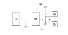
図7に比較例の圧縮機を示す。詳細な図示を省略するものの、比較例の圧縮機は実施例1の圧縮機とほぼ同様に構成されている。ここで、比較例の圧縮機では、実施例1の圧縮機における第1、2連通室18a、18b、壁部17c及び絞り通路20に換えて、ハウジング(図示略)に圧力調整室100、給気路101、抽気路102、制御弁103が設けられている。また、実施例1の圧縮機における制御路55に換えて、駆動軸(図示略)に制御路104が形成されている。比較例の圧縮機では、制御圧室13cと圧力調整室100とが制御路104によって連通している。また、圧力調整室100と第2吐出室29bとが給気路101によって連通している。さらに、圧力調整室100は抽気路102によって第2吸入室27bとも連通している。制御弁103は、第2吸入室27bの圧力により自己の開度を変更することにより、給気路101の開度を変更可能となっている。また、抽気路102には、オリフィス105が設けられている。比較例の圧縮機では、制御路104、給気路101、抽気路102、制御弁103及びオリフィス105によって制御機構150が構成されている。   FIG. 7 shows a compressor of a comparative example. Although the detailed illustration is omitted, the compressor of the comparative example is configured in substantially the same manner as the compressor of the first embodiment. Here, in the compressor of the comparative example, instead of the first and second communication chambers 18a and 18b, the wall portion 17c, and the throttle passage 20 in the compressor of the first embodiment, the pressure adjustment chamber 100 and the supply air are supplied to a housing (not shown). An air passage 101, an extraction passage 102, and a control valve 103 are provided. Further, a control path 104 is formed on a drive shaft (not shown) instead of the control path 55 in the compressor of the first embodiment. In the compressor of the comparative example, the control pressure chamber 13 c and the pressure adjustment chamber 100 communicate with each other through the control path 104. Further, the pressure adjusting chamber 100 and the second discharge chamber 29 b communicate with each other through the air supply path 101. Further, the pressure adjustment chamber 100 communicates with the second suction chamber 27b through the extraction passage 102. The control valve 103 can change the opening degree of the air supply path 101 by changing its own opening degree by the pressure of the second suction chamber 27b. The bleed passage 102 is provided with an orifice 105. In the compressor of the comparative example, a control mechanism 150 is configured by the control path 104, the supply path 101, the extraction path 102, the control valve 103, and the orifice 105.

比較例の圧縮機では、制御機構150は、圧力調整室100内の圧力を制御することによって、制御圧室13c内の圧力を制御する。具体的には、制御機構150において、制御弁103が自己の開度を小さくして給気路101の開度を小さくすれば、圧力調整室100内の圧力が減少する。このため、制御路104を通じて制御圧室13c内の圧力が減少することで、実施例1の圧縮機と同様に吐出容量が減少する。また、制御機構150において、制御弁103が自己の開度を大きくして給気路101の開度を大きくすれば、圧力調整室100内の圧力が増大するため、制御圧室13c内の圧力も増大する。このため、実施例1の圧縮機と同様に吐出容量が増大する。このように、比較例の圧縮機では、吐出容量を増減するに当たって、圧力調整室100内の圧力を調整する必要がある。このため、比較例の圧縮機では、制御弁103が開度を変更した際、吐出容量が増減されるまでに遅れが生じ易い。   In the compressor of the comparative example, the control mechanism 150 controls the pressure in the control pressure chamber 13c by controlling the pressure in the pressure adjustment chamber 100. Specifically, in the control mechanism 150, when the control valve 103 reduces the opening degree of the control valve 103 to reduce the opening degree of the air supply path 101, the pressure in the pressure regulation chamber 100 decreases. For this reason, when the pressure in the control pressure chamber 13c decreases through the control path 104, the discharge capacity decreases as in the compressor of the first embodiment. Further, in the control mechanism 150, if the control valve 103 increases its own opening to increase the opening of the air supply passage 101, the pressure in the pressure regulation chamber 100 increases, so Will also increase. For this reason, the discharge capacity increases as in the compressor of the first embodiment. Thus, in the compressor of the comparative example, it is necessary to adjust the pressure in the pressure adjusting chamber 100 when increasing or decreasing the discharge capacity. For this reason, in the compressor of the comparative example, when the control valve 103 changes the opening, a delay is likely to occur until the discharge capacity is increased or decreased.

これに対し、図1及び図2に示すように、実施例1の圧縮機では、作動時に第1通路59a及び給気経路61aを通じて、第1吐出室29a内の冷媒ガスが制御圧室13c内へ直接導入される。上記のように、この圧縮機では、第1、2吐出連通路12、14及び合流吐出室231を通じて第1吐出室29aと第2吐出室29bとが連通しているため、第2圧縮室53bで圧縮されて第2吐出室29bに吐出された冷媒ガスは、第1吐出室29aへ流通可能となっている。このため、実施例1の圧縮機では、たとえ第1圧縮室53aにおいて圧縮仕事が行われない場合であっても、第1吐出室29a内の冷媒ガスを制御圧室13c内へ導入することが可能となっている。そして、抽気経路61b及び第2通路59bを通じて制御圧室13c内の冷媒ガスが第2吸入室27b内へ直接導出される。これにより、実施例1の圧縮機では、比較例の圧縮機のように、制御圧室13cが圧力調整室100を介して第2吸入室27b及び第2吐出室29bと連通する場合と比較して、制御圧室13c内の圧力を素早く調整することができる。ここで、実施例1の圧縮機では、第1連通路18aを経由して第1吐出室29a内の冷媒ガスが制御圧室13c内へ導入され、制御圧室13c内の冷媒ガスは、第2連通路18bを経由して第2吸入室27b内へ導出される。しかし、第1、2連通路18a、18bは、上記の圧力調整室100のような制御圧室13c内の圧力の調整を行わない。   On the other hand, as shown in FIG. 1 and FIG. 2, in the compressor of the first embodiment, the refrigerant gas in the first discharge chamber 29a flows into the control pressure chamber 13c through the first passage 59a and the air supply passage 61a during operation. Introduced directly into. As described above, in this compressor, since the first discharge chamber 29a and the second discharge chamber 29b communicate with each other through the first and second discharge communication passages 12 and 14 and the merged discharge chamber 231, the second compression chamber 53b. The refrigerant gas compressed and discharged into the second discharge chamber 29b can flow to the first discharge chamber 29a. For this reason, in the compressor of the first embodiment, the refrigerant gas in the first discharge chamber 29a can be introduced into the control pressure chamber 13c even if the compression work is not performed in the first compression chamber 53a. It is possible. Then, the refrigerant gas in the control pressure chamber 13c is directly led into the second suction chamber 27b through the extraction passage 61b and the second passage 59b. Thereby, in the compressor of Example 1, compared with the case where the control pressure chamber 13c communicates with the second suction chamber 27b and the second discharge chamber 29b via the pressure adjustment chamber 100 as in the compressor of the comparative example. Thus, the pressure in the control pressure chamber 13c can be quickly adjusted. Here, in the compressor of the first embodiment, the refrigerant gas in the first discharge chamber 29a is introduced into the control pressure chamber 13c via the first communication path 18a, and the refrigerant gas in the control pressure chamber 13c is It is led into the second suction chamber 27b via the two communication passages 18b. However, the first and second communication passages 18a and 18b do not adjust the pressure in the control pressure chamber 13c like the pressure adjustment chamber 100 described above.

このため、実施例1の圧縮機では、必要に応じて移動体13aが斜板5の傾斜角度を素早く変更できるため、素早く吐出容量を増減することができる。また、この圧縮機では、制御路55に隔壁部材57が設けられているため、給気経路61aと抽気経路61bとが隔てられている。これにより、この圧縮機では、第1軸路55aを流通する冷媒ガスが第1径路55c及び制御圧室13cを経由せずに、直接第2軸路55bへ流通することが防止される。このため、この圧縮機では、制御圧室13c内の圧力を好適に調整することが可能となっている。   For this reason, in the compressor of Example 1, since the moving body 13a can change the inclination-angle of the swash plate 5 quickly as needed, discharge capacity can be increased / decreased rapidly. Moreover, in this compressor, since the partition member 57 is provided in the control path 55, the air supply path 61a and the extraction path 61b are separated. Thereby, in this compressor, it is prevented that the refrigerant gas which distribute | circulates the 1st axial path 55a distribute | circulates directly to the 2nd axial path 55b, without passing through the 1st path 55c and the control pressure chamber 13c. For this reason, in this compressor, it is possible to adjust the pressure in the control pressure chamber 13c suitably.

したがって、実施例1の圧縮機は高い制御性を発揮する。   Therefore, the compressor of Example 1 exhibits high controllability.

また、この圧縮機では、制御圧室13c内の圧力を調整するに当たって、制御弁24aによって抽気路22の開度を大きくすることにより、制御圧室13c内の圧力を素早く低下させることが可能となっている。また、この圧縮機では、第1吐出室29a内から制御圧室13c内へ導入する冷媒ガスの流量は、絞り通路20によって調整される。このため、制御圧室13b内から第2吸入室27b内へ導出される冷媒ガスの流量のみを制御弁24aで調整すれば足りる。このため、この圧縮機では、リヤハウジング19に制御弁24aを1つ設ければ良く、製造コストを低廉化することが可能となっている。   Moreover, in this compressor, when adjusting the pressure in the control pressure chamber 13c, it is possible to quickly reduce the pressure in the control pressure chamber 13c by increasing the opening degree of the extraction passage 22 by the control valve 24a. It has become. In this compressor, the flow rate of the refrigerant gas introduced from the first discharge chamber 29 a into the control pressure chamber 13 c is adjusted by the throttle passage 20. Therefore, it is sufficient to adjust only the flow rate of the refrigerant gas led out from the control pressure chamber 13b to the second suction chamber 27b by the control valve 24a. For this reason, in this compressor, it is only necessary to provide one control valve 24a in the rear housing 19, and the manufacturing cost can be reduced.

(実施例2)
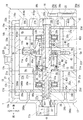
図8及び図9に示すように、実施例2の圧縮機では、制御機構15に換えて制御機構16を備えている。また、図10に示すように、この圧縮機では、フロントハウジング17に対して、第1軸孔17b、第1連通室18a、壁部17c及び絞り通路20が形成されていない。これにより、この圧縮機では、第1吸入室27aがフロントハウジング17の中心側に配置されている。
(Example 2)
As shown in FIGS. 8 and 9, the compressor according to the second embodiment includes a control mechanism 16 instead of the control mechanism 15. Further, as shown in FIG. 10, in this compressor, the first shaft hole 17 b, the first communication chamber 18 a, the wall portion 17 c, and the throttle passage 20 are not formed in the front housing 17. Thus, in this compressor, the first suction chamber 27 a is disposed on the center side of the front housing 17.

また、図8に示すように、この圧縮機では、リヤハウジング19に対して、抽気路22及び制御弁24aに換えて給気路26及び制御弁24bが設けられている。給気路26は、第1給気路26aと第2給気路26bとで構成されている。第1給気路26aは、第2吐出室29bと制御弁24bとに接続している。第2給気路26bは、制御弁24bと第2連通室18bとに接続している。また、リヤハウジング19には、第2吸入室27bと制御弁24bとを接続する接続路28が形成されている。制御弁24bは、第2吸入室27b内の冷媒ガスの圧力に基づいて自己の開度を変更することにより、給気路26の開度を調整することが可能となっている。   Further, as shown in FIG. 8, in this compressor, an air supply passage 26 and a control valve 24b are provided for the rear housing 19 in place of the extraction passage 22 and the control valve 24a. The air supply path 26 includes a first air supply path 26a and a second air supply path 26b. The first air supply path 26a is connected to the second discharge chamber 29b and the control valve 24b. The second air supply path 26b is connected to the control valve 24b and the second communication chamber 18b. The rear housing 19 is formed with a connection path 28 that connects the second suction chamber 27b and the control valve 24b. The control valve 24b can adjust the opening of the air supply passage 26 by changing its own opening based on the pressure of the refrigerant gas in the second suction chamber 27b.

この圧縮機では、駆動軸3は、ハウジング1内において、軸封装置25、第1吸入室27a、第2連通室18b、第2、3軸孔21b、23b、第1、2弁形成プレート39、41、斜板室33及び第1、2スラスト軸受35a、35bに挿通されている。これにより、図10に示すように、第1支持部材43aは、軸封装置25、第1吸入室27a、第1弁形成プレート39及び第1スラスト軸受35aに挿通されつつ、第2軸孔21bに支持されている。また、実施例1の圧縮機と異なり、この圧縮機では、第1支持部材43aに第1、2環状溝431、432及び第1、2封止部材44a、44bが設けられていない。   In this compressor, in the housing 1, the drive shaft 3 includes a shaft seal device 25, a first suction chamber 27 a, a second communication chamber 18 b, second and third shaft holes 21 b and 23 b, first and second valve forming plates 39. 41, the swash plate chamber 33 and the first and second thrust bearings 35a and 35b. As a result, as shown in FIG. 10, the first support member 43a is inserted into the shaft seal device 25, the first suction chamber 27a, the first valve forming plate 39, and the first thrust bearing 35a, and the second shaft hole 21b. It is supported by. Further, unlike the compressor of the first embodiment, in this compressor, the first and second annular grooves 431 and 432 and the first and second sealing members 44a and 44b are not provided in the first support member 43a.

さらに、駆動軸3には、第3径路55eに換えて、第4径路55f及び絞り通路32が形成されている。第4径路55f及び絞り通路32は、駆動軸3の前端側に形成されている。第4径路55fは、第1支持部43aの径方向に延びており、第1支持部43aの外周面に開口している。絞り通路32は、第1軸路55a及び第4径路55fよりも小径に形成されている。絞り通路32は、第4径路55fと同軸で駆動軸本体30の径方向に延びて、第1軸路55aの前端側と第4径路55fとに接続している。絞り通路32も本発明における絞りの一例である。第4径路55f及び絞り通路32は、上記のように駆動軸3がハウジング1に支承されることにより、第1吸入室27a内に位置する。   Further, the drive shaft 3 is formed with a fourth path 55f and a throttle path 32 instead of the third path 55e. The fourth path 55 f and the throttle path 32 are formed on the front end side of the drive shaft 3. The fourth path 55f extends in the radial direction of the first support portion 43a and opens on the outer peripheral surface of the first support portion 43a. The throttle passage 32 is formed with a smaller diameter than the first axial path 55a and the fourth radial path 55f. The throttle passage 32 is coaxial with the fourth path 55f and extends in the radial direction of the drive shaft main body 30, and is connected to the front end side of the first axis 55a and the fourth path 55f. The throttle passage 32 is also an example of a throttle in the present invention. The fourth passage 55f and the throttle passage 32 are located in the first suction chamber 27a when the drive shaft 3 is supported by the housing 1 as described above.

図8に示すように、この圧縮機では、第4径路55f及び絞り通路32によって、第1軸路55a及び第1径路55cが第1吸入室27aと連通している。また、第2連通室18b、給気路26及び制御弁24bによって、第2軸路55b及び第2径路55cが第2吐出室29bと連通している。つまり、この圧縮機では、第4径路55f及び絞り通路32によって、制御路55を第1吸入室27aに連通させる第1通路60aが構成されている。また、第2連通室18b、給気路26及び制御弁24bによって、制御路55を第2吐出室29aに連通させる第2通路60bが構成されている。   As shown in FIG. 8, in this compressor, the first axial path 55a and the first radial path 55c are communicated with the first suction chamber 27a by the fourth path 55f and the throttle path 32. The second axial path 55b and the second radial path 55c communicate with the second discharge chamber 29b by the second communication chamber 18b, the air supply path 26, and the control valve 24b. In other words, in the compressor, the fourth passage 55f and the throttle passage 32 constitute a first passage 60a that allows the control passage 55 to communicate with the first suction chamber 27a. Further, the second communication chamber 18b, the air supply passage 26, and the control valve 24b constitute a second passage 60b that allows the control passage 55 to communicate with the second discharge chamber 29a.

そして、この圧縮機では、制御路55のうち、第2軸路55b及び第2径路55dによって、第2吐出室29b内の冷媒ガスが制御圧室13c内へ至る給気経路63aが構成されている。また、制御路55のうち、第1軸路55a及び第1径路55cによって、制御圧室13c内の冷媒ガスが第1吸入室27a内へ至る抽気経路63bが構成されている。実施例1の圧縮機と同様、これらの給気経路63aと抽気経路63bとについても、隔壁部材57によって隔てられている。   In this compressor, an air supply path 63a through which the refrigerant gas in the second discharge chamber 29b reaches the control pressure chamber 13c is configured by the second axial path 55b and the second path 55d in the control path 55. Yes. Further, in the control path 55, the first axial path 55a and the first path 55c constitute an extraction path 63b through which the refrigerant gas in the control pressure chamber 13c reaches the first suction chamber 27a. As with the compressor of the first embodiment, the air supply path 63a and the extraction path 63b are also separated by a partition wall member 57.

図9に示すように、制御機構16は、制御路55と、第1通路60aと、第2通路60bとを有している。制御機構16は、第2通路60b及び制御路55を流通させて、第2吐出室29b内の冷媒ガスを制御圧室13c内に導入するとともに、制御路55及び第1通路60aを流通させて、制御圧室13c内の冷媒ガスを第1吸入室27a内へ導出する。この際、制御弁24bは第2通路60bの開度を変更し、絞り通路32は第1通路60aの開度を絞る。こうして、制御機構16は、制御圧室13c内の圧力を制御する。この圧縮機における他の構成は実施例1の圧縮機と同様であり、同一の構成については同一の符号を付して構成に関する詳細な説明を省略する。   As shown in FIG. 9, the control mechanism 16 includes a control path 55, a first passage 60a, and a second passage 60b. The control mechanism 16 circulates the second passage 60b and the control passage 55 to introduce the refrigerant gas in the second discharge chamber 29b into the control pressure chamber 13c, and circulates the control passage 55 and the first passage 60a. Then, the refrigerant gas in the control pressure chamber 13c is led out into the first suction chamber 27a. At this time, the control valve 24b changes the opening degree of the second passage 60b, and the throttle passage 32 restricts the opening degree of the first passage 60a. Thus, the control mechanism 16 controls the pressure in the control pressure chamber 13c. Other configurations of the compressor are the same as those of the compressor according to the first embodiment, and the same components are denoted by the same reference numerals and detailed description thereof is omitted.

この圧縮機では、制御機構16は、第2通路60b及び給気経路63a、すなわち、給気路26、第2連通室18b、第2軸路55b及び第2径路55dを流通させて、第2吐出室29b内の冷媒ガスが制御圧室13c内に導入する。そして、抽気経路63b及び第1通路60a、すなわち、第1径路55c、第1軸路55a、絞り通路32及び第4径路55fを流通させて、制御圧室13c内の冷媒ガスを第1吸入室27a内へ導出する。この際、絞り通路32によって、制御圧室13c内から第1吸入室27a内へ導出される冷媒ガスの流量が調整される。   In this compressor, the control mechanism 16 causes the second passage 60b and the air supply path 63a, that is, the air supply path 26, the second communication chamber 18b, the second axial path 55b, and the second path 55d to circulate, and the second. The refrigerant gas in the discharge chamber 29b is introduced into the control pressure chamber 13c. Then, the refrigerant passage in the control pressure chamber 13c is circulated through the extraction passage 63b and the first passage 60a, that is, the first passage 55c, the first axial passage 55a, the throttle passage 32, and the fourth passage 55f. Derived into 27a. At this time, the flow rate of the refrigerant gas led out from the control pressure chamber 13c into the first suction chamber 27a is adjusted by the throttle passage 32.

ここで、制御機構16において、制御弁24bが第2吸入室27b内の冷媒ガスの圧力に基づいて給気路26の開度を小さくすれば、第2吐出室29b内から制御圧室13c内へ導入される冷媒ガスの流量が減少する。この結果、制御圧室13c内の圧力が減少し、可変差圧が小さくなる。このため、実施例1の圧縮機と同様、移動体13aが斜板室33の後方に向かって移動し、斜板5の傾斜角度が減少して、駆動軸3の1回転当たりの吐出容量が減少する。   Here, in the control mechanism 16, if the control valve 24b reduces the opening of the air supply passage 26 based on the pressure of the refrigerant gas in the second suction chamber 27b, the inside of the control pressure chamber 13c from the second discharge chamber 29b. The flow rate of the refrigerant gas introduced into is reduced. As a result, the pressure in the control pressure chamber 13c decreases and the variable differential pressure becomes smaller. Therefore, like the compressor of the first embodiment, the moving body 13a moves toward the rear of the swash plate chamber 33, the inclination angle of the swash plate 5 decreases, and the discharge capacity per one rotation of the drive shaft 3 decreases. To do.

一方、制御機構16において、制御弁24bが給気路26の開度を大きくすれば、第2吐出室29b内から制御圧室13c内へ導入される冷媒ガスの流量が増大する。この結果、第2吐出室29b内の冷媒ガスの圧力によって、制御圧室13c内の圧力が増大し、可変差圧が大きくなる。これにより、移動体13aが斜板室33の前方に向かって移動し、斜板5の傾斜角度が増大して、駆動軸3の1回転当たりの吐出容量が増大する。   On the other hand, in the control mechanism 16, when the control valve 24b increases the opening of the air supply passage 26, the flow rate of the refrigerant gas introduced from the second discharge chamber 29b into the control pressure chamber 13c increases. As a result, the pressure in the control pressure chamber 13c increases due to the pressure of the refrigerant gas in the second discharge chamber 29b, and the variable differential pressure increases. Thereby, the moving body 13a moves toward the front of the swash plate chamber 33, the inclination angle of the swash plate 5 increases, and the discharge capacity per one rotation of the drive shaft 3 increases.

このように、この圧縮機では、作動時に第2通路60b及び給気経路63aを通じて、第2吐出室29b内の冷媒ガスが制御圧室13c内へ直接導入される。また、抽気経路63b及び第1通路60aを通じて制御圧室13c内の冷媒ガスが第1吸入室27a内へ直接導出される。このため、実施例1の圧縮機と同様、この圧縮機でも、必要に応じて移動体13aが斜板5の傾斜角度を素早く変更できるため、素早く吐出容量を増減することができる。また、この圧縮機でも、隔壁部材57によって、給気経路63aと抽気経路63bとが隔てられているため、第2軸路55bを流通する冷媒ガスが第2径路55d及び制御圧室13cを経由せずに、直接第1軸路55aへ流通することが防止される。このため、この圧縮機でも、制御圧室13c内の圧力を好適に調整することが可能となっている。   Thus, in this compressor, the refrigerant gas in the second discharge chamber 29b is directly introduced into the control pressure chamber 13c through the second passage 60b and the air supply path 63a during operation. Further, the refrigerant gas in the control pressure chamber 13c is directly led into the first suction chamber 27a through the extraction passage 63b and the first passage 60a. For this reason, like the compressor of Example 1, also in this compressor, since the moving body 13a can change the inclination-angle of the swash plate 5 quickly as needed, discharge capacity can be increased / decreased quickly. Also in this compressor, since the air supply path 63a and the extraction path 63b are separated by the partition wall member 57, the refrigerant gas flowing through the second axial path 55b passes through the second path 55d and the control pressure chamber 13c. Without flowing, it is prevented from flowing directly to the first axis 55a. For this reason, even in this compressor, it is possible to suitably adjust the pressure in the control pressure chamber 13c.

また、この圧縮機では、制御圧室13c内の圧力を調整するに当たって、制御弁24bによって給気路26の開度を大きくすることにより、制御圧室13c内の圧力を素早く増大させることが可能となっている。そして、制御圧室13c内から第1吸入室27a内へ導出される冷媒ガスの流量は、絞り通路32によって調整されるため、この圧縮機でもリヤハウジング19に制御弁24bを1つ設ければ足りる。このため、この圧縮機でも製造コストを低廉化することが可能となっている。   Further, in this compressor, when adjusting the pressure in the control pressure chamber 13c, it is possible to quickly increase the pressure in the control pressure chamber 13c by increasing the opening of the air supply passage 26 by the control valve 24b. It has become. Since the flow rate of the refrigerant gas led out from the control pressure chamber 13c into the first suction chamber 27a is adjusted by the throttle passage 32, even if this compressor is provided with one control valve 24b in the rear housing 19. It ’s enough. For this reason, the manufacturing cost can be reduced even with this compressor.

さらに、この圧縮機では、第1吸入室27a内に駆動軸3が挿通されており、第1吸入室27a内において、第1軸路55aは第4径路55f及び絞り通路32を通じて第1吸入室27aと連通している。このため、この圧縮機では、実施例1の圧縮機と異なり、フロントハウジング17aに第1連通室18a、壁部17c及び絞り通路20を設ける必要がないとともに、第1支持部材43aに第1、2封止部材44a、44bを設ける必要がない。また、駆動軸本体30に絞り通路32を形成することにより、第1通路60aの開度を絞るための絞り通路32を容易に設けることが可能となっている。このため、この圧縮機では、製造を容易化することができ、この点においても製造コストを低廉化することが可能となっている。この圧縮機における他の作用は実施例1の圧縮機と同様である。   Further, in this compressor, the drive shaft 3 is inserted into the first suction chamber 27a. In the first suction chamber 27a, the first shaft path 55a passes through the fourth path 55f and the throttle passage 32, and the first suction chamber 27a. It communicates with 27a. Therefore, in this compressor, unlike the compressor of the first embodiment, it is not necessary to provide the first communication chamber 18a, the wall portion 17c, and the throttle passage 20 in the front housing 17a, and the first support member 43a has the first, 2 There is no need to provide the sealing members 44a and 44b. Further, by forming the throttle passage 32 in the drive shaft main body 30, it is possible to easily provide the throttle passage 32 for narrowing the opening degree of the first passage 60a. For this reason, in this compressor, manufacture can be facilitated, and also in this respect, manufacturing cost can be reduced. Other functions of this compressor are the same as those of the compressor of the first embodiment.

以上において、本発明を実施例1、2に即して説明したが、本発明は上記実施例1、2に制限されるものではなく、その趣旨を逸脱しない範囲で適宜変更して適用できることはいうまでもない。   In the above, the present invention has been described with reference to the first and second embodiments. However, the present invention is not limited to the first and second embodiments, and can be appropriately modified and applied without departing from the spirit of the present invention. Needless to say.

例えば、実施例1、2の圧縮機において、第1シリンダブロック21や第2シリンダブロック23に制御弁24aや制御弁24bを配置しても良い。   For example, in the compressors of the first and second embodiments, the control valve 24a and the control valve 24b may be arranged in the first cylinder block 21 and the second cylinder block 23.

また、実施例1、2の圧縮機において、斜板室33内において、アクチュエータ13を斜板5よりも後方に配置し、リンク機構7を斜板5よりも前方に配置する構成としても良い。   In the compressors of the first and second embodiments, the actuator 13 may be disposed behind the swash plate 5 and the link mechanism 7 may be disposed forward of the swash plate 5 in the swash plate chamber 33.

さらに、実施例1の圧縮機において、制御弁24aをフロントハウジング17に配置するとともに、絞り通路20を抽気路22に設ける構成としても良い。   Further, in the compressor according to the first embodiment, the control valve 24 a may be disposed in the front housing 17 and the throttle passage 20 may be provided in the extraction passage 22.

また、実施例1の圧縮機において、絞り通路20に換えて、第1吐出室29a内から制御圧室13c内へ導入される冷媒ガスの流量を制御弁24aとは別の制御弁によって調整しても良い。   In the compressor of the first embodiment, the flow rate of the refrigerant gas introduced from the first discharge chamber 29a into the control pressure chamber 13c is adjusted by a control valve different from the control valve 24a, instead of the throttle passage 20. May be.

さらに、実施例2の圧縮機において、制御弁24bをフロントハウジング17に配置するとともに、絞り通路32を給気路26に設ける構成としても良い。   Furthermore, in the compressor according to the second embodiment, the control valve 24b may be disposed in the front housing 17 and the throttle passage 32 may be provided in the air supply passage 26.

また、実施例2の圧縮機において、絞り通路32に換えて、制御圧室13c内から第1吸入室27a内へ導出される冷媒ガスの流量を制御弁24bとは別の制御弁によって調整しても良い。   In the compressor of the second embodiment, the flow rate of the refrigerant gas led out from the control pressure chamber 13c into the first suction chamber 27a is adjusted by a control valve different from the control valve 24b instead of the throttle passage 32. May be.

さらに、実施例1の圧縮機では、第2吸入室27b内の圧力に基づいて、抽気路22、すなわち、第2通路59bの開度を変更する制御弁24aを採用している。しかし、これに限らず、流量制御弁を採用して抽気路22の開度を変更しても良い。この場合、冷凍回路の吐出領域内に第1圧力監視点が設定されるとともに、冷凍回路の吐出領域内において、第1圧力監視点よりも冷媒ガスの流通方向の下流であって、第1圧力監視点よりも低圧となる箇所に第2圧力監視点が設定される。これにより、流量制御弁は、第1圧力監視点と第2圧力監視点との差圧に基づき、抽気路22の開度を変更することが可能となる。実施例2の圧縮機についても同様に、流量制御弁によって給気路26の開度を変更しても良い。   Furthermore, in the compressor of Example 1, the control valve 24a which changes the opening degree of the extraction path 22, ie, the 2nd channel | path 59b based on the pressure in the 2nd suction chamber 27b is employ | adopted. However, the present invention is not limited to this, and the opening degree of the bleed passage 22 may be changed by employing a flow rate control valve. In this case, a first pressure monitoring point is set in the discharge region of the refrigeration circuit, and the first pressure is further downstream in the flow direction of the refrigerant gas than the first pressure monitoring point in the discharge region of the refrigeration circuit. A second pressure monitoring point is set at a location where the pressure is lower than the monitoring point. Thereby, the flow control valve can change the opening degree of the extraction passage 22 based on the differential pressure between the first pressure monitoring point and the second pressure monitoring point. Similarly, in the compressor of the second embodiment, the opening degree of the air supply path 26 may be changed by the flow rate control valve.

本発明は空調装置等に利用可能である。   The present invention can be used for an air conditioner or the like.

1…ハウジング
3…駆動軸
5…斜板
7…リンク機構
9…ピストン
9a…第1頭部
9b…第2頭部
13a…移動体
13b…区画体
13c…制御圧室
15、16…制御機構
20…絞り通路(絞り)
21a…第1シリンダボア
23a…第2シリンダボア
24a、24b…制御弁
27a…第1吸入室
27b…第2吸入室
29a…第1吐出室
29b…第2吐出室
32…絞り通路(絞り)
55…制御路
57…隔壁部材(隔壁)
59a、60a…第1通路
59b、60b…第2通路
61a、63a…給気経路
61b、63b…抽気経路
DESCRIPTION OF SYMBOLS 1 ... Housing 3 ... Drive shaft 5 ... Swash plate 7 ... Link mechanism 9 ... Piston 9a ... 1st head 9b ... 2nd head 13a ... Moving body 13b ... Partition body 13c ... Control pressure chamber 15, 16 ... Control mechanism 20 ... throttle passage (throttle)
21a ... first cylinder bore 23a ... second cylinder bores 24a, 24b ... control valve 27a ... first suction chamber 27b ... second suction chamber 29a ... first discharge chamber 29b ... second discharge chamber 32 ... throttle passage (throttle)
55 ... Control path 57 ... Partition member (partition wall)
59a, 60a ... 1st passage 59b, 60b ... 2nd passage 61a, 63a ... Air supply route 61b, 63b ... Extraction route

Claims (4)

吸入室、吐出室、斜板室及び複数のシリンダボアが形成されたハウジングと、
前記ハウジングに回転可能に支承された駆動軸と、
前記斜板室内に配置されて前記駆動軸とともに回転される斜板と、
前記駆動軸の回転軸心に直交する方向に対する前記斜板の傾斜角度の変更を許容するリンク機構と、
前記各シリンダボアに収納され、前記斜板の回転によって前記傾斜角度に応じたストロークで往復動して前記各シリンダボア内に圧縮室を形成するピストンと、
前記斜板室内で前記駆動軸と一体回転可能に設けられた区画体と、
前記斜板室内で前記駆動軸と一体回転可能であり、かつ前記区画体に対して前記回転軸心方向に移動して前記傾斜角度を変更する移動体と、
前記区画体と前記移動体とにより区画され、内部の圧力によって前記移動体を移動させる制御圧室と、
前記制御圧室内の圧力を制御する制御機構とを備え、
前記吸入室は、前記斜板の一面側に位置する第1吸入室と、前記斜板の他面側に位置する第2吸入室とからなり、
前記吐出室は、前記斜板の前記一面側に位置する第1吐出室と、前記斜板の前記他面側に位置する第2吐出室とからなり、
前記各シリンダボアは、前記斜板の前記一面側に設けられ、前記第1吸入室及び前記第1吐出室と連通する第1シリンダボアと、前記斜板の前記他面側に設けられ、前記第2吸入室及び前記第2吐出室と連通する第2シリンダボアとからなり、
前記各ピストンは、前記第1シリンダボア内を往復動して、前記第1シリンダボア内に第1圧縮室を区画する第1頭部と、前記第2シリンダボア内を往復動して、前記第2シリンダボア内に第2圧縮室を区画する第2頭部とを有し、
前記制御機構は、前記駆動軸の内部に形成され、前記制御圧室に連通する制御路と、
前記ハウジング及び前記駆動軸の少なくとも一方に形成され、前記制御路を前記第1吐出室又は前記第1吸入室に連通させる第1通路と、
前記ハウジング及び前記駆動軸の少なくとも一方に形成され、前記第1通路が前記第1吐出室に連通すれば前記制御路を前記第2吸入室に連通させ、前記第1通路が前記第1吸入室に連通すれば前記制御路を前記第2吐出室に連通させる第2通路と、
前記第1通路及び前記第2通路のうちの一方側の通路に設けられ、前記一方側の通路の開度を変更可能な制御弁と、
前記第1通路及び前記第2通路のうちの他方側の通路に設けられ、前記他方側の通路の開度を絞る絞り又は前記他方側の通路の開度を変更可能な前記制御弁とを有していることを特徴とする容量可変型斜板式圧縮機。
A housing in which a suction chamber, a discharge chamber, a swash plate chamber and a plurality of cylinder bores are formed;
A drive shaft rotatably supported on the housing;
A swash plate disposed in the swash plate chamber and rotated together with the drive shaft;
A link mechanism that allows a change in the inclination angle of the swash plate with respect to the direction orthogonal to the rotational axis of the drive shaft;
A piston that is housed in each cylinder bore and reciprocates at a stroke according to the tilt angle by rotation of the swash plate to form a compression chamber in each cylinder bore;
A partition provided in the swash plate chamber so as to be integrally rotatable with the drive shaft;
A movable body that is integrally rotatable with the drive shaft in the swash plate chamber and that moves in the direction of the rotational axis relative to the partition body to change the tilt angle;
A control pressure chamber that is partitioned by the partition body and the moving body and moves the moving body by an internal pressure;
A control mechanism for controlling the pressure in the control pressure chamber,
The suction chamber comprises a first suction chamber located on one side of the swash plate and a second suction chamber located on the other side of the swash plate,
The discharge chamber is composed of a first discharge chamber located on the one surface side of the swash plate and a second discharge chamber located on the other surface side of the swash plate,
The cylinder bores are provided on the one surface side of the swash plate, provided on the other surface side of the swash plate, a first cylinder bore communicating with the first suction chamber and the first discharge chamber, and the second A second cylinder bore communicating with the suction chamber and the second discharge chamber;
Each piston reciprocates within the first cylinder bore, reciprocates within the first cylinder bore and a first head that defines a first compression chamber, and the second cylinder bore, and the second cylinder bore. A second head that defines a second compression chamber therein,
The control mechanism is formed inside the drive shaft and communicates with the control pressure chamber;
A first passage formed in at least one of the housing and the drive shaft and communicating the control path with the first discharge chamber or the first suction chamber;
If formed in at least one of the housing and the drive shaft, and the first passage communicates with the first discharge chamber, the control passage communicates with the second suction chamber, and the first passage communicates with the first suction chamber. A second passage for communicating the control path with the second discharge chamber if communicating with the second discharge chamber;
A control valve provided in one of the first and second passages and capable of changing an opening of the one passage;
Provided in a passage on the other side of the first passage and the second passage, and has a throttle for restricting the opening of the other passage or the control valve capable of changing the opening of the other passage. This is a variable capacity swash plate compressor.
前記第1通路は、前記制御路を前記第1吐出室に連通させ、
前記第2通路は、前記制御路を前記第2吸入室に連通させ、
前記制御弁は、前記第2通路に設けられ、
前記第1通路には、前記絞りが設けられ、
前記制御路には、前記第1吐出室の冷媒が前記制御圧室へ至る給気経路と、前記制御圧室の前記冷媒が前記第2吸入室へ至る抽気経路と、前記給気経路と前記抽気経路とを隔てる隔壁とが形成されている請求項1記載の容量可変型斜板式圧縮機。
The first passage communicates the control path with the first discharge chamber,
The second passage communicates the control path with the second suction chamber,
The control valve is provided in the second passage,
The throttle is provided in the first passage,
The control path includes an air supply path for the refrigerant in the first discharge chamber to reach the control pressure chamber, an air extraction path for the refrigerant in the control pressure chamber to reach the second suction chamber, the air supply path, and the The variable capacity swash plate compressor according to claim 1, wherein a partition wall separating the bleed passage is formed.
前記第1通路は、前記制御路を前記第1吸入室に連通させ、
前記第2通路は、前記制御路を前記第2吐出室に連通させ、
前記制御弁は、前記第2通路に設けられ、
前記第1通路には、前記絞りが設けられ、
前記制御路には、前記第2吐出室の冷媒が前記制御圧室へ至る給気経路と、前記制御圧室の前記冷媒が前記第1吸入室へ至る抽気経路と、前記給気経路と前記抽気経路とを隔てる隔壁とが形成されている請求項1記載の容量可変型斜板式圧縮機。
The first passage communicates the control path with the first suction chamber,
The second passage communicates the control path with the second discharge chamber,
The control valve is provided in the second passage,
The throttle is provided in the first passage,
The control path includes an air supply path for the refrigerant in the second discharge chamber to reach the control pressure chamber, an air extraction path for the refrigerant in the control pressure chamber to reach the first suction chamber, the air supply path, and the The variable capacity swash plate compressor according to claim 1, wherein a partition wall separating the bleed passage is formed.
前記第1吐出室は前記第1吸入室の外周に配置され、
前記駆動軸は前記第1吸入室内に挿通され、
前記絞りは、前記駆動軸に設けられている請求項3記載の容量可変型斜板式圧縮機。
The first discharge chamber is disposed on an outer periphery of the first suction chamber;
The drive shaft is inserted into the first suction chamber;
4. The variable displacement swash plate compressor according to claim 3, wherein the throttle is provided on the drive shaft.
JP2016049793A 2016-03-14 2016-03-14 Variable displacement swash plate compressor Pending JP2017166336A (en)

Priority Applications (1)

Application Number Priority Date Filing Date Title
JP2016049793A JP2017166336A (en) 2016-03-14 2016-03-14 Variable displacement swash plate compressor

Applications Claiming Priority (1)

Application Number Priority Date Filing Date Title
JP2016049793A JP2017166336A (en) 2016-03-14 2016-03-14 Variable displacement swash plate compressor

Publications (1)

Publication Number Publication Date
JP2017166336A true JP2017166336A (en) 2017-09-21

Family

ID=59910104

Family Applications (1)

Application Number Title Priority Date Filing Date
JP2016049793A Pending JP2017166336A (en) 2016-03-14 2016-03-14 Variable displacement swash plate compressor

Country Status (1)

Country Link
JP (1) JP2017166336A (en)

Cited By (1)

* Cited by examiner, † Cited by third party
Publication number Priority date Publication date Assignee Title
CN113677889A (en) * 2019-03-27 2021-11-19 株式会社丰田自动织机 Piston type compressor

Cited By (1)

* Cited by examiner, † Cited by third party
Publication number Priority date Publication date Assignee Title
CN113677889A (en) * 2019-03-27 2021-11-19 株式会社丰田自动织机 Piston type compressor

Similar Documents

Publication Publication Date Title
JP6003547B2 (en) Variable capacity swash plate compressor
JP6028525B2 (en) Variable capacity swash plate compressor
JP2014092105A (en) Variable displacement swash plate type compressor
JP2018204439A (en) Variable displacement swash plate-type compressor
JP6194837B2 (en) Variable capacity swash plate compressor
JP5983657B2 (en) Variable capacity swash plate compressor
JP2017166336A (en) Variable displacement swash plate compressor
KR101597266B1 (en) Swash plate type variable displacement compressor
JP6287483B2 (en) Variable capacity swash plate compressor
JP6201852B2 (en) Variable capacity swash plate compressor
WO2014156799A1 (en) Variable-capacity swash plate-type compressor
JP6179438B2 (en) Variable capacity swash plate compressor
JP2017166335A (en) Variable displacement swash plate compressor
JP2017172367A (en) Variable displacement swash plate compressor
JP5949678B2 (en) Variable capacity swash plate compressor
JP2016160749A (en) Variable displacement swash plate compressor
JP6179439B2 (en) Variable capacity swash plate compressor
JP2018159277A (en) Variable displacement swash plate compressor
JP2017172366A (en) Variable displacement swash plate compressor
JP6115397B2 (en) Variable capacity swash plate compressor
JP6107528B2 (en) Variable capacity swash plate compressor
JP2018150902A (en) Capacity variable swash plate compressor
JP2017180095A (en) Variable displacement swash plate compressor
JP2018145929A (en) Variable capacity-type swash plate compressor
JP2017172420A (en) Variable displacement swash plate compressor