JP2017166327A - Honeycomb-type heating device and method of use and manufacturing thereof - Google Patents
Honeycomb-type heating device and method of use and manufacturing thereof Download PDFInfo
- Publication number
- JP2017166327A JP2017166327A JP2016049311A JP2016049311A JP2017166327A JP 2017166327 A JP2017166327 A JP 2017166327A JP 2016049311 A JP2016049311 A JP 2016049311A JP 2016049311 A JP2016049311 A JP 2016049311A JP 2017166327 A JP2017166327 A JP 2017166327A
- Authority
- JP
- Japan
- Prior art keywords
- honeycomb
- outer peripheral
- peripheral surface
- heater
- heaters
- Prior art date
- Legal status (The legal status is an assumption and is not a legal conclusion. Google has not performed a legal analysis and makes no representation as to the accuracy of the status listed.)
- Granted
Links
Images


Classifications
-
- F—MECHANICAL ENGINEERING; LIGHTING; HEATING; WEAPONS; BLASTING
- F01—MACHINES OR ENGINES IN GENERAL; ENGINE PLANTS IN GENERAL; STEAM ENGINES
- F01N—GAS-FLOW SILENCERS OR EXHAUST APPARATUS FOR MACHINES OR ENGINES IN GENERAL; GAS-FLOW SILENCERS OR EXHAUST APPARATUS FOR INTERNAL-COMBUSTION ENGINES
- F01N3/00—Exhaust or silencing apparatus having means for purifying, rendering innocuous, or otherwise treating exhaust
- F01N3/08—Exhaust or silencing apparatus having means for purifying, rendering innocuous, or otherwise treating exhaust for rendering innocuous
- F01N3/10—Exhaust or silencing apparatus having means for purifying, rendering innocuous, or otherwise treating exhaust for rendering innocuous by thermal or catalytic conversion of noxious components of exhaust
- F01N3/24—Exhaust or silencing apparatus having means for purifying, rendering innocuous, or otherwise treating exhaust for rendering innocuous by thermal or catalytic conversion of noxious components of exhaust characterised by constructional aspects of converting apparatus
- F01N3/28—Construction of catalytic reactors
- F01N3/2803—Construction of catalytic reactors characterised by structure, by material or by manufacturing of catalyst support
- F01N3/2825—Ceramics
- F01N3/2828—Ceramic multi-channel monoliths, e.g. honeycombs
-
- B—PERFORMING OPERATIONS; TRANSPORTING
- B01—PHYSICAL OR CHEMICAL PROCESSES OR APPARATUS IN GENERAL
- B01D—SEPARATION
- B01D53/00—Separation of gases or vapours; Recovering vapours of volatile solvents from gases; Chemical or biological purification of waste gases, e.g. engine exhaust gases, smoke, fumes, flue gases, aerosols
- B01D53/34—Chemical or biological purification of waste gases
- B01D53/92—Chemical or biological purification of waste gases of engine exhaust gases
- B01D53/94—Chemical or biological purification of waste gases of engine exhaust gases by catalytic processes
-
- B—PERFORMING OPERATIONS; TRANSPORTING
- B01—PHYSICAL OR CHEMICAL PROCESSES OR APPARATUS IN GENERAL
- B01J—CHEMICAL OR PHYSICAL PROCESSES, e.g. CATALYSIS OR COLLOID CHEMISTRY; THEIR RELEVANT APPARATUS
- B01J27/00—Catalysts comprising the elements or compounds of halogens, sulfur, selenium, tellurium, phosphorus or nitrogen; Catalysts comprising carbon compounds
- B01J27/20—Carbon compounds
- B01J27/22—Carbides
- B01J27/224—Silicon carbide
-
- B—PERFORMING OPERATIONS; TRANSPORTING
- B01—PHYSICAL OR CHEMICAL PROCESSES OR APPARATUS IN GENERAL
- B01J—CHEMICAL OR PHYSICAL PROCESSES, e.g. CATALYSIS OR COLLOID CHEMISTRY; THEIR RELEVANT APPARATUS
- B01J35/00—Catalysts, in general, characterised by their form or physical properties
- B01J35/40—Catalysts, in general, characterised by their form or physical properties characterised by dimensions, e.g. grain size
-
- B—PERFORMING OPERATIONS; TRANSPORTING
- B01—PHYSICAL OR CHEMICAL PROCESSES OR APPARATUS IN GENERAL
- B01J—CHEMICAL OR PHYSICAL PROCESSES, e.g. CATALYSIS OR COLLOID CHEMISTRY; THEIR RELEVANT APPARATUS
- B01J35/00—Catalysts, in general, characterised by their form or physical properties
- B01J35/50—Catalysts, in general, characterised by their form or physical properties characterised by their shape or configuration
- B01J35/56—Foraminous structures having flow-through passages or channels, e.g. grids or three-dimensional [3D] monoliths
- B01J35/57—Honeycombs
-
- B—PERFORMING OPERATIONS; TRANSPORTING
- B01—PHYSICAL OR CHEMICAL PROCESSES OR APPARATUS IN GENERAL
- B01J—CHEMICAL OR PHYSICAL PROCESSES, e.g. CATALYSIS OR COLLOID CHEMISTRY; THEIR RELEVANT APPARATUS
- B01J37/00—Processes, in general, for preparing catalysts; Processes, in general, for activation of catalysts
- B01J37/02—Impregnation, coating or precipitation
- B01J37/0215—Coating
- B01J37/0221—Coating of particles
-
- F—MECHANICAL ENGINEERING; LIGHTING; HEATING; WEAPONS; BLASTING
- F01—MACHINES OR ENGINES IN GENERAL; ENGINE PLANTS IN GENERAL; STEAM ENGINES
- F01N—GAS-FLOW SILENCERS OR EXHAUST APPARATUS FOR MACHINES OR ENGINES IN GENERAL; GAS-FLOW SILENCERS OR EXHAUST APPARATUS FOR INTERNAL-COMBUSTION ENGINES
- F01N3/00—Exhaust or silencing apparatus having means for purifying, rendering innocuous, or otherwise treating exhaust
- F01N3/08—Exhaust or silencing apparatus having means for purifying, rendering innocuous, or otherwise treating exhaust for rendering innocuous
- F01N3/10—Exhaust or silencing apparatus having means for purifying, rendering innocuous, or otherwise treating exhaust for rendering innocuous by thermal or catalytic conversion of noxious components of exhaust
- F01N3/18—Exhaust or silencing apparatus having means for purifying, rendering innocuous, or otherwise treating exhaust for rendering innocuous by thermal or catalytic conversion of noxious components of exhaust characterised by methods of operation; Control
- F01N3/20—Exhaust or silencing apparatus having means for purifying, rendering innocuous, or otherwise treating exhaust for rendering innocuous by thermal or catalytic conversion of noxious components of exhaust characterised by methods of operation; Control specially adapted for catalytic conversion
- F01N3/2006—Periodically heating or cooling catalytic reactors, e.g. at cold starting or overheating
- F01N3/2013—Periodically heating or cooling catalytic reactors, e.g. at cold starting or overheating using electric or magnetic heating means
- F01N3/2026—Periodically heating or cooling catalytic reactors, e.g. at cold starting or overheating using electric or magnetic heating means directly electrifying the catalyst substrate, i.e. heating the electrically conductive catalyst substrate by joule effect
-
- H—ELECTRICITY
- H05—ELECTRIC TECHNIQUES NOT OTHERWISE PROVIDED FOR
- H05B—ELECTRIC HEATING; ELECTRIC LIGHT SOURCES NOT OTHERWISE PROVIDED FOR; CIRCUIT ARRANGEMENTS FOR ELECTRIC LIGHT SOURCES, IN GENERAL
- H05B3/00—Ohmic-resistance heating
- H05B3/10—Heating elements characterised by the composition or nature of the materials or by the arrangement of the conductor
- H05B3/16—Heating elements characterised by the composition or nature of the materials or by the arrangement of the conductor the conductor being mounted on an insulating base
-
- H—ELECTRICITY
- H05—ELECTRIC TECHNIQUES NOT OTHERWISE PROVIDED FOR
- H05B—ELECTRIC HEATING; ELECTRIC LIGHT SOURCES NOT OTHERWISE PROVIDED FOR; CIRCUIT ARRANGEMENTS FOR ELECTRIC LIGHT SOURCES, IN GENERAL
- H05B2203/00—Aspects relating to Ohmic resistive heating covered by group H05B3/00
- H05B2203/017—Manufacturing methods or apparatus for heaters
-
- H—ELECTRICITY
- H05—ELECTRIC TECHNIQUES NOT OTHERWISE PROVIDED FOR
- H05B—ELECTRIC HEATING; ELECTRIC LIGHT SOURCES NOT OTHERWISE PROVIDED FOR; CIRCUIT ARRANGEMENTS FOR ELECTRIC LIGHT SOURCES, IN GENERAL
- H05B2203/00—Aspects relating to Ohmic resistive heating covered by group H05B3/00
- H05B2203/022—Heaters specially adapted for heating gaseous material
- H05B2203/024—Heaters using beehive flow through structures
Landscapes
- Chemical & Material Sciences (AREA)
- Engineering & Computer Science (AREA)
- Chemical Kinetics & Catalysis (AREA)
- Materials Engineering (AREA)
- Organic Chemistry (AREA)
- Combustion & Propulsion (AREA)
- Health & Medical Sciences (AREA)
- Mechanical Engineering (AREA)
- Toxicology (AREA)
- General Engineering & Computer Science (AREA)
- Ceramic Engineering (AREA)
- Biomedical Technology (AREA)
- Environmental & Geological Engineering (AREA)
- Analytical Chemistry (AREA)
- General Chemical & Material Sciences (AREA)
- Oil, Petroleum & Natural Gas (AREA)
- Exhaust Gas After Treatment (AREA)
- Exhaust Gas Treatment By Means Of Catalyst (AREA)
- Catalysts (AREA)
Abstract
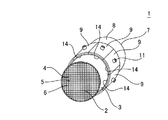
【課題】ヒーターの一部が破損しても加熱が可能であるとともに、ヒーターからハニカム基材に効率良く熱を伝達することが可能なハニカム型加熱装置並びにその使用方法及び製造方法を提供する。【解決手段】一方の端面から他方の端面まで延びる複数のセルを区画形成する隔壁と、前記隔壁を取り囲む外周壁3とを有する柱状のハニカム基材2、外周壁3の外側表面である外周面8の周方向に沿って、外周面8上に隣接配置された複数のヒーター9、及び、ハニカム基材2の外周面8と複数のヒーター9との間に挟み込まれた中間材14とを備え、ハニカム基材2の外周面8と複数のヒーター9との間において中間材14が外周面8を覆っている部分の面積の合計が、複数のヒーター9が外周面8を覆っている部分の面積の合計の20〜100%であるハニカム型加熱装置1。【選択図】図1The present invention provides a honeycomb type heating apparatus capable of heating even if a part of the heater is broken, and capable of efficiently transferring heat from the heater to a honeycomb substrate, and a method of using and a method of manufacturing the same. A columnar honeycomb substrate 2 having a partition wall defining a plurality of cells extending from one end surface to the other end surface, and an outer peripheral wall 3 surrounding the partition wall, and an outer peripheral surface which is an outer surface of the outer peripheral wall 3 8, a plurality of heaters 9 arranged adjacent to each other on the outer peripheral surface 8, and an intermediate member 14 sandwiched between the outer peripheral surface 8 of the honeycomb substrate 2 and the plurality of heaters 9. The total area of the portion where the intermediate material 14 covers the outer peripheral surface 8 between the outer peripheral surface 8 of the honeycomb substrate 2 and the plurality of heaters 9 is the portion of the portion where the plurality of heaters 9 cover the outer peripheral surface 8. A honeycomb type heating device 1 having a total area of 20 to 100%. [Selection] Figure 1
Description
本発明は、自動車等のエンジンから排出される排ガスの排気経路に設置され、排ガス浄化用の触媒を、その活性温度まで早期に昇温させるためのハニカム型加熱装置、当該ハニカム型加熱装置の使用方法、及び当該ハニカム型加熱装置の製造方法に関する。 The present invention is a honeycomb-type heating device that is installed in an exhaust path of exhaust gas discharged from an engine such as an automobile and quickly raises the catalyst for exhaust gas purification to its activation temperature, and use of the honeycomb-type heating device The present invention relates to a method and a method for manufacturing the honeycomb heating apparatus.
従来、自動車等のエンジンから排出される排ガス中に含まれるHC、CO、NOx等の有害物質の浄化処理のため、ハニカム構造体に触媒を担持したものが使用されている。このように、ハニカム構造体に担持した触媒によって排ガスを処理する場合、触媒をその活性温度まで昇温する必要があるが、エンジン始動時には、触媒が活性温度に達していないため、排ガスが十分に浄化されないという問題があった。特に、プラグインハイブリッド車(PHEV)やハイブリッド車(HV)は、その走行に、モーターのみによる走行を含むことから、エンジン始動頻度が少なく、エンジン始動時の触媒温度が低いため、エンジン始動直後の排ガス浄化性能が悪化し易い。 Conventional, HC contained in exhaust gas discharged from an engine of an automobile or the like, CO, for purification treatment of harmful substances such as NO x, those carrying a catalyst is used in the honeycomb structure. As described above, when the exhaust gas is treated with the catalyst supported on the honeycomb structure, it is necessary to raise the temperature of the catalyst to its activation temperature. However, when the engine is started, the catalyst has not reached the activation temperature. There was a problem that it was not purified. In particular, plug-in hybrid vehicles (PHEV) and hybrid vehicles (HV) include traveling only by a motor in their traveling, so the engine start frequency is low and the catalyst temperature at engine starting is low. Exhaust gas purification performance tends to deteriorate.
この問題を解決するため、導電性セラミックスからなるハニカム構造体に電極を配設し、通電によりハニカム構造体自体を発熱させることで、触媒をエンジン始動前に活性温度まで昇温できるようにした電気加熱触媒(EHC)が提案されている(特許文献1参照)。 In order to solve this problem, an electrode is arranged on a honeycomb structure made of conductive ceramics, and the honeycomb structure itself generates heat by energization so that the catalyst can be heated to an activation temperature before starting the engine. A heating catalyst (EHC) has been proposed (see Patent Document 1).
また、ハニカム構造体の外周壁を取り囲むように、筒状の抵抗加熱式ヒーターを配置し、ハニカム構造体の外周壁の壁面を加熱することで、内部のセル構造物に熱を伝達するようにした加熱装置も提案されている(特許文献2参照)。 In addition, a cylindrical resistance heater is disposed so as to surround the outer peripheral wall of the honeycomb structure, and heat is transferred to the internal cell structure by heating the wall surface of the outer peripheral wall of the honeycomb structure. A heating apparatus has also been proposed (see Patent Document 2).
しかしながら、通電によりハニカム構造体自体を発熱させる方式では、振動等によりハニカム構造体に軽度のクラックが生じただけでも、ハニカム構造体内を流れる電流の経路が変化して、温度の低下や温度分布の変化が生じるため、耐久性が十分とは言えない。 However, in the method of heating the honeycomb structure itself by energization, even if a slight crack is generated in the honeycomb structure due to vibration or the like, the path of the current flowing through the honeycomb structure changes, and the temperature drop or temperature distribution Since changes occur, the durability is not sufficient.
一方、ハニカム構造体の外周壁を取り囲むように、筒状の抵抗加熱式ヒーターを配置する方式では、ハニカム構造体は、外部のヒーターによって加熱されるため、振動等によりハニカム構造体に軽度のクラックが生じても、ハニカム構造体の温度変化は少ない。しかし、筒状のヒーターは、熱応力による破損が生じ易い。そして、単一(一体構造)の抵抗加熱式ヒーターによる加熱では、そのヒーターが破損して通電できなくなると、ハニカム構造体全体が全く加熱されなくなる。また、ヒーターとハニカム構造体との間に存在する隙間や、ハニカム構造体の外周壁表面(外周面)の微小な凹凸のため、ヒーターとハニカム構造体の外周壁表面との間の熱抵抗が大きく、ヒーターからハニカム構造体に効率良く熱を伝達することが困難であった。 On the other hand, in the system in which the cylindrical resistance heating heater is arranged so as to surround the outer peripheral wall of the honeycomb structure, since the honeycomb structure is heated by an external heater, a slight crack is caused in the honeycomb structure by vibration or the like. Even if this occurs, the temperature change of the honeycomb structure is small. However, the cylindrical heater is easily damaged by thermal stress. In the heating by a single (integrated structure) resistance heating type heater, if the heater is damaged and cannot be energized, the entire honeycomb structure is not heated at all. In addition, there is a gap between the heater and the honeycomb structure and minute irregularities on the outer peripheral wall surface (outer peripheral surface) of the honeycomb structure, so that the thermal resistance between the heater and the outer peripheral wall surface of the honeycomb structure is low. It is large and it is difficult to efficiently transfer heat from the heater to the honeycomb structure.
本発明は、このような従来の事情に鑑みてなされたものである。即ち、本発明は、ヒーターの一部が破損しても加熱が可能であるとともに、ヒーターからハニカム構造体(ハニカム基材)に効率良く熱を伝達することが可能なハニカム型加熱装置並びにその使用方法及び製造方法を提供することを目的とする。 The present invention has been made in view of such conventional circumstances. That is, the present invention provides a honeycomb type heating apparatus capable of heating even if a part of the heater is broken, and capable of efficiently transferring heat from the heater to the honeycomb structure (honeycomb base material), and use thereof. It is an object to provide a method and a manufacturing method.
上記目的を達成するため、本発明によれば、以下のハニカム型加熱装置、ハニカム型加熱装置の使用方法及びハニカム型加熱装置の製造方法が提供される。 In order to achieve the above object, according to the present invention, there are provided the following honeycomb type heating device, method of using the honeycomb type heating device, and method of manufacturing the honeycomb type heating device.
[1] 一方の端面から他方の端面まで延びる複数のセルを区画形成する隔壁と、前記隔壁を取り囲む外周壁とを有する柱状のハニカム基材、前記外周壁の外側表面である外周面の周方向に沿って、当該外周面上に隣接配置された複数のヒーター、及び、前記ハニカム基材の前記外周面と前記複数のヒーターとの間に挟み込まれた中間材を備え、前記ハニカム基材の前記外周面と前記複数のヒーターとの間において前記中間材が前記外周面を覆っている部分の面積の合計が、前記複数のヒーターが前記外周面を覆っている部分の面積の合計の20〜100%であるハニカム型加熱装置。 [1] A columnar honeycomb substrate having partition walls that form a plurality of cells extending from one end face to the other end face, and an outer peripheral wall that surrounds the partition walls, and a circumferential direction of the outer peripheral face that is the outer surface of the outer peripheral wall A plurality of heaters arranged adjacent to each other on the outer peripheral surface, and an intermediate member sandwiched between the outer peripheral surface of the honeycomb base material and the plurality of heaters, and the honeycomb base material The total area of the portion where the intermediate material covers the outer peripheral surface between the outer peripheral surface and the plurality of heaters is 20 to 100 of the total area of the portion where the plurality of heaters cover the outer peripheral surface. % Honeycomb type heating device.
[2] 前記中間材の少なくとも一部の熱伝導率が、1W/m・K以上である[1]に記載のハニカム型加熱装置。 [2] The honeycomb heating device according to [1], wherein the thermal conductivity of at least a part of the intermediate material is 1 W / m · K or more.
[3] 前記中間材のヤング率が、0.01〜30GPaである[1]又は[2]に記載のハニカム型加熱装置。 [3] The honeycomb heating apparatus according to [1] or [2], wherein the intermediate material has a Young's modulus of 0.01 to 30 GPa.
[4] 前記中間材の気孔率が、0〜70%である[1]〜[3]の何れかに記載のハニカム型加熱装置。 [4] The honeycomb heating apparatus according to any one of [1] to [3], wherein the porosity of the intermediate material is 0 to 70%.
[5] 前記中間材が、無機粒子と無機結合材とを含むものである[1]〜[4]の何れかに記載のハニカム型加熱装置。 [5] The honeycomb heating apparatus according to any one of [1] to [4], wherein the intermediate material includes inorganic particles and an inorganic binder.
[6] 前記無機粒子の平均粒子径が、1〜100μmである[5]に記載のハニカム型加熱装置。 [6] The honeycomb heating apparatus according to [5], wherein the inorganic particles have an average particle diameter of 1 to 100 μm.
[7] 前記各ヒーターが、通電により発熱する抵抗加熱式ヒーターである[1]〜[6]の何れかに記載のハニカム型加熱装置。 [7] The honeycomb heating device according to any one of [1] to [6], wherein each of the heaters is a resistance heating heater that generates heat when energized.
[8] 前記各ヒーターが、化学反応により発生する反応熱を利用して発熱する反応熱式ヒーターである[1]〜[6]の何れかに記載のハニカム型加熱装置。 [8] The honeycomb heating apparatus according to any one of [1] to [6], wherein each of the heaters is a reaction heat heater that generates heat using reaction heat generated by a chemical reaction.
[9] 前記複数のヒーターが、電気的に直列又は並列に接続されており、200V以上の高電圧を通電できるような電気抵抗を有する[7]に記載のハニカム型加熱装置。 [9] The honeycomb heating device according to [7], wherein the plurality of heaters are electrically connected in series or in parallel and have an electric resistance that allows a high voltage of 200 V or more to be passed.
[10] 前記各ヒーターが、前記各ヒーターから前記ハニカム基材へ電流が流れるのを防止するための絶縁機能を有する[7]又は[9]に記載のハニカム型加熱装置。 [10] The honeycomb heating apparatus according to [7] or [9], wherein each heater has an insulating function for preventing current from flowing from each heater to the honeycomb substrate.
[11] 前記ハニカム基材が、熱伝導率が20W/m・K以上のセラミック材料で構成されている[1]〜[10]の何れかに記載のハニカム型加熱装置。 [11] The honeycomb heating apparatus according to any one of [1] to [10], wherein the honeycomb substrate is made of a ceramic material having a thermal conductivity of 20 W / m · K or more.
[12] 前記外周壁の厚さが、前記隔壁の厚さよりも厚い[1]〜[11]の何れかに記載のハニカム型加熱装置。 [12] The honeycomb heating apparatus according to any one of [1] to [11], wherein the outer peripheral wall is thicker than the partition wall.
[13] 前記ハニカム基材に、ストレスレリーフが形成されている[1]〜[12]の何れかに記載のハニカム型加熱装置。 [13] The honeycomb heating apparatus according to any one of [1] to [12], wherein a stress relief is formed on the honeycomb substrate.
[14] 前記ハニカム基材に排ガス浄化用の触媒を担持させた[1]〜[13]の何れかに記載のハニカム型加熱装置。 [14] The honeycomb heating apparatus according to any one of [1] to [13], wherein a catalyst for exhaust gas purification is supported on the honeycomb substrate.
[15] エンジンから排出される排ガスの排気経路に設置され、前記エンジンの始動前に、前記各ヒーターを発熱させて、排ガス浄化用の触媒を担持させた前記ハニカム基材を、前記触媒の触媒活性温度以上の温度に昇温させるために使用される[14]に記載のハニカム型加熱装置。 [15] The honeycomb base material, which is installed in the exhaust path of exhaust gas discharged from the engine and heats each heater to carry the exhaust gas purification catalyst before starting the engine, is used as the catalyst catalyst. The honeycomb heating apparatus according to [14], which is used to raise the temperature to a temperature equal to or higher than the activation temperature.
[16] [1]〜[15]の何れかに記載のハニカム型加熱装置が、筒状のキャニングケースに収納されたキャニング済みハニカム型加熱装置。 [16] A canned honeycomb heating apparatus in which the honeycomb heating apparatus according to any one of [1] to [15] is housed in a cylindrical canning case.
[17] 一方の端面から他方の端面まで延びる複数のセルを区画形成する隔壁と、前記隔壁を取り囲む外周壁とを有する柱状のハニカム基材、前記外周壁の外側表面である外周面の周方向に沿って、当該外周面上に隣接配置された複数のヒーター、及び、前記ハニカム基材の前記外周面と前記複数のヒーターとの間に挟み込まれた中間材を備え、前記ハニカム基材の前記外周面と前記複数のヒーターとの間において前記中間材が前記外周面を覆っている部分の面積の合計が、前記複数のヒーターが前記外周面を覆っている部分の面積の合計の20〜100%であり、前記ハニカム基材に排ガス浄化用の触媒を担持させたハニカム型加熱装置を、エンジンから排出される排ガスの排気経路に設置し、前記エンジンの始動前に前記各ヒーターを発熱させて、前記ハニカム基材を、前記触媒の触媒活性温度以上の温度に昇温させるハニカム型加熱装置の使用方法。 [17] A columnar honeycomb substrate having partition walls that form a plurality of cells extending from one end face to the other end face, and an outer peripheral wall that surrounds the partition walls, and a circumferential direction of the outer peripheral face that is the outer surface of the outer peripheral wall A plurality of heaters arranged adjacent to each other on the outer peripheral surface, and an intermediate member sandwiched between the outer peripheral surface of the honeycomb base material and the plurality of heaters, and the honeycomb base material The total area of the portion where the intermediate material covers the outer peripheral surface between the outer peripheral surface and the plurality of heaters is 20 to 100 of the total area of the portion where the plurality of heaters cover the outer peripheral surface. A honeycomb type heating device in which a catalyst for exhaust gas purification is supported on the honeycomb base material is installed in an exhaust path of exhaust gas discharged from the engine, and each heater is turned on before starting the engine. Heated thereby and, the honeycomb substrate, the use of honeycomb heater for raising the temperature of the catalyst activation temperature or higher temperature of the catalyst.
[18] 一方の端面から他方の端面まで延びる複数のセルを区画形成する隔壁と、前記隔壁を取り囲む外周壁とを有する柱状のハニカム基材、前記外周壁の外側表面である外周面の周方向に沿って、当該外周面上に隣接配置された複数のヒーター、及び、前記ハニカム基材の前記外周面と前記複数のヒーターとの間に挟み込まれた中間材を備え、前記ハニカム基材の前記外周面と前記複数のヒーターとの間において前記中間材が前記外周面を覆っている部分の面積の合計が、前記複数のヒーターが前記外周面を覆っている部分の面積の合計の20〜100%であるハニカム型加熱装置を、前記ハニカム基材の外周面の前記各ヒーターが配置される部位、及び/又は前記各ヒーターの前記ハニカム基材の外周面と対向する面に、SiC粒子とコロイダルシリカとを含む中間材形成用のペーストを塗布するペースト塗布工程と、前記ペースト塗布工程後に、前記複数のヒーターを、前記ペーストを挟んで、前記ハニカム基材の前記外周面の周方向に沿って、前記外周面上に隣接配置するヒーター配置工程と、前記ヒーター配置工程後に、前記ペーストを加熱して乾燥させることにより、前記ペーストから前記中間材を形成する中間材形成工程とを含む方法によって製造するハニカム型加熱装置の製造方法。 [18] A columnar honeycomb substrate having partition walls that form a plurality of cells extending from one end face to the other end face, and an outer peripheral wall that surrounds the partition walls, and a circumferential direction of the outer peripheral face that is the outer surface of the outer peripheral wall A plurality of heaters arranged adjacent to each other on the outer peripheral surface, and an intermediate member sandwiched between the outer peripheral surface of the honeycomb base material and the plurality of heaters, and the honeycomb base material The total area of the portion where the intermediate material covers the outer peripheral surface between the outer peripheral surface and the plurality of heaters is 20 to 100 of the total area of the portion where the plurality of heaters cover the outer peripheral surface. % Of the honeycomb-type heating device on a portion of the outer peripheral surface of the honeycomb substrate on which the heaters are disposed and / or a surface of the heater facing the outer peripheral surface of the honeycomb substrate. A paste applying step of applying a paste for forming an intermediate material containing a toroidal silica; and after the paste applying step, the plurality of heaters are sandwiched between the pastes along the circumferential direction of the outer peripheral surface of the honeycomb substrate. Manufactured by a method including: a heater arranging step adjacently arranged on the outer peripheral surface; and an intermediate material forming step of forming the intermediate material from the paste by heating and drying the paste after the heater arranging step. A method for manufacturing a honeycomb heating apparatus.
[19] 前記ペースト塗布工程の前に、前記ハニカム基材の前記隔壁に、排ガス浄化用の触媒を担持させる触媒担持工程を更に含む[18]に記載のハニカム型加熱装置の製造方法。 [19] The method for manufacturing a honeycomb heating apparatus according to [18], further including a catalyst supporting step of supporting an exhaust gas purifying catalyst on the partition walls of the honeycomb base before the paste applying step.
本発明のハニカム型加熱装置においては、ハニカム基材の外周面と複数のヒーターとの間に挟み込まれた中間材により、複数のヒーターとハニカム基材との間の隙間が充填されるとともに、ハニカム基材の外周壁表面の微小な凹凸が吸収される。そして、その結果、複数のヒーターとハニカム基材の外周壁表面との間の熱抵抗が小さくなり、ヒーターの熱をハニカム基材に効率良く伝達できる。また、本発明のハニカム型加熱装置は、ハニカム基材自体が発熱するものではなく、ハニカム基材に取り付けられた複数のヒーターにより加熱されるものであるため、ハニカム基材に軽度のクラックが生じても、ハニカム基材の温度変化が少ない。更に、本発明のハニカム型加熱装置は、複数のヒーターによってハニカム基材を加熱するため、一部のヒーターが破損して発熱しなくなっても、残りの発熱可能なヒーターで、ハニカム基材を加熱することができる。また、それら複数のヒーターは、ハニカム基材の外周面の周方向において隣接しているものの、互いに分断された分割構造となっているため、個々のヒーターには大きな熱応力が生じ難く、ヒーターが破損し難い。 In the honeycomb heating device of the present invention, the intermediate material sandwiched between the outer peripheral surface of the honeycomb substrate and the plurality of heaters fills the gaps between the plurality of heaters and the honeycomb substrate, and Minute irregularities on the outer peripheral wall surface of the substrate are absorbed. As a result, the thermal resistance between the plurality of heaters and the outer peripheral wall surface of the honeycomb substrate is reduced, and the heat of the heater can be efficiently transferred to the honeycomb substrate. In the honeycomb heating apparatus of the present invention, the honeycomb base material itself does not generate heat, but is heated by a plurality of heaters attached to the honeycomb base material. However, the temperature change of the honeycomb substrate is small. Furthermore, since the honeycomb substrate heating apparatus of the present invention heats the honeycomb substrate with a plurality of heaters, even if some of the heaters break and do not generate heat, the remaining heater can heat the honeycomb substrate. can do. In addition, although the plurality of heaters are adjacent to each other in the circumferential direction of the outer peripheral surface of the honeycomb substrate, they have a divided structure that is divided from each other. Hard to break.
また、本発明のキャニング済みハニカム型加熱装置においては、本発明のハニカム型加熱装置が既にキャニングケース内に収納されているため、そのまま排ガスの排気経路に設置して使用することができる。 In the canned honeycomb heating apparatus of the present invention, since the honeycomb heating apparatus of the present invention is already stored in the canning case, it can be used as it is in the exhaust gas exhaust path.
更に、本発明のハニカム型加熱装置の使用方法によれば、エンジン始動前に各ヒーターを発熱させて、排ガス浄化用の触媒を担持させたハニカム基材を、触媒の触媒活性温度以上の温度に昇温させることができる。そして、その結果、エンジン始動直後から、活性化した触媒により、排ガス中に含まれる有害成分を効率良く浄化することが可能となる。 Furthermore, according to the method for using the honeycomb heating device of the present invention, the honeycomb substrate carrying the exhaust gas purifying catalyst is heated to a temperature equal to or higher than the catalyst activation temperature of the catalyst by causing each heater to generate heat before starting the engine. The temperature can be raised. As a result, it becomes possible to efficiently purify harmful components contained in the exhaust gas with the activated catalyst immediately after the engine is started.
更にまた、本発明のハニカム型加熱装置の製造方法によれば、上記のような優れた効果を有する本発明のハニカム型加熱装置を製造することができる。 Furthermore, according to the method for manufacturing a honeycomb type heating apparatus of the present invention, the honeycomb type heating apparatus of the present invention having the excellent effects as described above can be manufactured.
以下、本発明を具体的な実施形態に基づき説明するが、本発明は、それらの実施形態に限定されて解釈されるものではなく、本発明の趣旨を逸脱しない範囲で、当業者の通常の知識に基づいて、適宜設計の変更、改良等を加え得るものである。 Hereinafter, the present invention will be described based on specific embodiments. However, the present invention is not construed as being limited to these embodiments, and is within the scope of the present invention. Based on the knowledge, design changes and improvements can be added as appropriate.
(1)ハニカム型加熱装置:
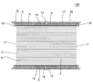
図1は、本発明のハニカム型加熱装置の実施形態の一例を示す概略斜視図である。また、図2は、本発明のハニカム型加熱装置の実施形態の一例を、当該装置の長さ方向(軸方向)に垂直な断面で示す概略断面図であり、図3は、本発明のハニカム型加熱装置の実施形態の一例を、当該装置の長さ方向(軸方向)に平行な断面で示す概略断面図である。これら図1〜3に示すように、本発明のハニカム型加熱装置1は、ハニカム基材2と、複数のヒーター9と中間材14とを備える。
(1) Honeycomb type heating device:
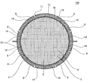
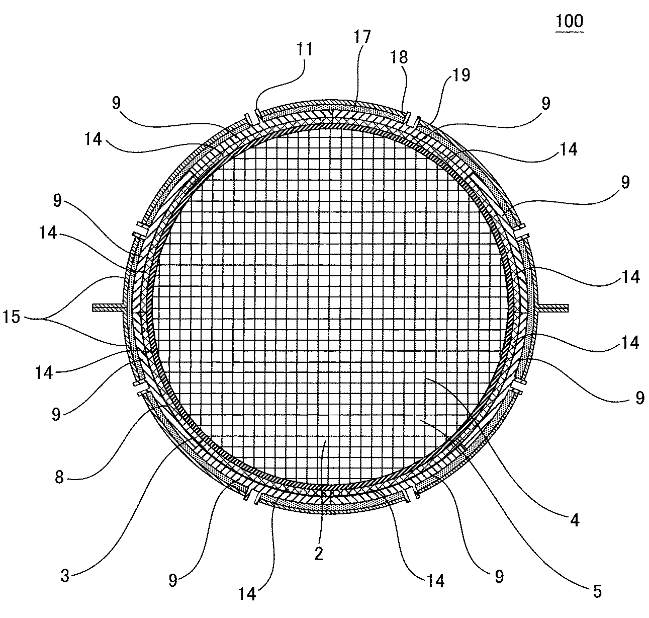
FIG. 1 is a schematic perspective view showing an example of an embodiment of a honeycomb type heating apparatus of the present invention. FIG. 2 is a schematic cross-sectional view showing an example of an embodiment of the honeycomb type heating apparatus of the present invention in a cross section perpendicular to the length direction (axial direction) of the apparatus, and FIG. 3 is a honeycomb of the present invention. It is a schematic sectional drawing which shows an example of embodiment of a type | mold heating apparatus with a cross section parallel to the length direction (axial direction) of the said apparatus. As shown in FIGS. 1 to 3, the
ハニカム基材2は、柱状で、一方の端面6から他方の端面7まで延びる複数のセル5を区画形成する隔壁4と、隔壁4を取り囲む外周壁3とを有する。セル5は、排ガス等の流体の流路となる。複数のヒーター9は、ハニカム基材2の外周壁3の外側表面(外部に露出している側の面)である外周面8の周方向に沿って、外周面8上に隣接配置されている。中間材14は、ハニカム基材2の外周面8と複数のヒーター9との間に挟み込まれた状態で配置されている。
The
図1〜3に示す実施形態において、各ヒーター9は、通電により発熱する抵抗加熱式ヒーターである。本実施形態においては、各ヒーター9に、電気配線を接続するための電極端子突起部11が設けられている。この電極端子突起部11は、筒状に形成されており、その内部にヒーター9の電極端子が配置されている。そして、この電極端子に接続された電気配線を通じて、電源から各ヒーター9に通電される。尚、本発明において使用可能なヒーターの種類は、抵抗加熱式ヒーターに限定されるものではない。例えば、前記のような抵抗加熱式ヒーターの代わりに、化学反応により発生する反応熱を利用して発熱する反応熱式ヒーター等を用いてもよい。反応熱式ヒーターの例としては、特開2014−111913号公報に開示されている化学蓄熱ユニットのような、NH3と、MgCl2、CaCl2、NiCl2、ZnCl2、SrCl2等とを化学反応させ、当該反応により発生する熱を利用して発熱させるものが挙げられる。
In the embodiment shown in FIGS. 1 to 3, each
本発明のハニカム型加熱装置1においては、ハニカム基材2の外周面8と複数のヒーター9との間に、中間材14が介在することにより、複数のヒーター9とハニカム基材2との間の隙間が充填されるとともに、ハニカム基材2の外周面8の微小な凹凸が吸収される。そして、その結果、複数のヒーター9とハニカム基材2の外周面8との間の熱抵抗が小さくなり、複数のヒーター9の熱をハニカム基材2に効率良く伝達できる。中間材14は、少なくともその一部が、1W/m・K以上の熱伝導率を有することが好ましく、1.5W/m・K以上の熱伝導率を有することがより好ましく、2W/m・K以上の熱伝導率を有することが更に好ましい。中間材14が、このような高い熱伝導率を有することにより、複数のヒーター9の熱をハニカム基材2により効率良く伝達できるようになる。中間材14の少なくとも一部における熱伝導率の上限については、特に限定はされない。但し、通常、ハニカム基材2の熱伝導率は、高くても150W/m・K程度であり、中間材14の熱伝導率を、ハニカム基材2の熱伝導率より高くしても、伝熱性能の大きな向上は見込めない。よって、中間材14の熱伝導率の上限は、150W/m・K程度とすることが好ましい。尚、本発明において、中間材の熱伝導率は、中間材から、直径5mm×厚さ1mmの円板状の測定用試料を切り出し、JIS R 1611に準拠した方法により測定した値である。
In the
また、本発明のハニカム型加熱装置1においては、複数のヒーター9によってハニカム基材2を加熱するため、一部のヒーター9が破損して発熱しなくなっても、残りの発熱可能なヒーター9で、ハニカム基材2を加熱することができる。尚、本発明のハニカム型加熱装置1は、ハニカム基材2自体が発熱するものではなく、ハニカム基材2に取り付けられた複数のヒーター9により加熱されるものであるため、ハニカム基材2に軽度のクラックが生じても、ハニカム基材2の温度変化は少ない。
Further, in the honeycomb
更に、本発明のハニカム型加熱装置1に使用される複数のヒーター9は、ハニカム基材2の外周面8の周方向において隣接しているものの、互いに分断された分割構造となっているため、個々のヒーター9には大きな熱応力が生じ難い。このため、これら複数のヒーター9は、特許文献2に開示されているような、筒状で単一のヒーターに比べ、熱応力による破損が起こり難く、耐久性に優れる。尚、本発明において、「隣接」とは、隣り合うヒーター同士が直接接触している状態だけでなく、ある程度の間隔をおいて近接している状態も含む。本発明のハニカム型加熱装置1においては、加熱効率の観点から、少なくとも一部の隣接しているヒーター9同士が直接接触していることが好ましく、全ての隣接しているヒーター9同士が直接接触していることがより好ましい。
Furthermore, although the plurality of
本発明のハニカム型加熱装置1においては、ハニカム基材2の外周面8と複数のヒーター9との間において中間材14が外周面8を覆っている部分の面積の合計が、複数のヒーター9が外周面8を覆っている部分の面積の合計の20〜100%である。以降の記載において、「ハニカム基材2の外周面8と複数のヒーター9との間において中間材14が外周面8を覆っている部分の面積の合計」のことを、「中間材設置面積」ということがある。また、「複数のヒーター9が外周面8を覆っている部分の面積の合計」のことを「ヒーター設置面積」ということがある。中間材設置面積は、ヒーター設置面積の50〜100%であることが好ましく、ヒーター設置面積の80〜100%であることが特に好ましい。ヒーター設置面積に対する中間材設置面積の割合が、このような範囲にあると、ハニカム基材2の外周面8と複数のヒーター9との間に中間材14を介在させたことによる熱伝達の向上効果が顕著に発現される。中間材設置面積が、ヒーター設置面積の20%未満だと、ハニカム基材2の外周面8と複数のヒーター9との間に中間材14を介在させたことによる熱伝達の向上効果が十分に得られないことがある。
In the
中間材14は、そのヤング率が、0.01〜30GPaであることが好ましく、0.1〜20GPaであることがより好ましく、0.1〜10GPaであることが特に好ましい。中間材14のヤング率がこのような範囲にあると、中間材14がハニカム基材2の外周面8及びヒーター9と密着し易く、複数のヒーター9とハニカム基材2の外周面8との間の熱抵抗を十分に小さくすることができる。尚、本発明において、中間材のヤング率は、JIS R 1602に準拠して、曲げ共振法によって測定した値である。測定用の試料(試験片)は、以下の方法で作製した。まず、中間材を形成する原料を用いてバルク体を作製した。そして、このバルク体から3mm×4mm×40mmの大きさに切り出したものを、測定用の試料とした。
The
中間材14は、その気孔率が、0〜70%であることが好ましく、5〜60%であることがより好ましく、10〜50%であることが特に好ましい。中間材14の気孔率がこのような範囲にあると、中間材14に必要な強度を確保し易くなるとともに、高い熱伝導率が得られ易くなる。尚、本発明において、中間材の気孔率は、アルキメデス法により測定した値である。
The porosity of the
中間材14の厚さは、100〜2000μmであることが好ましく、100〜1000μmであることがより好ましく、100〜500μmであることが特に好ましい。中間材14の厚さがこのような範囲にあると、中間材14によって、複数のヒーター9とハニカム基材2との間の隙間が充填され易くなり、その結果、複数のヒーター9とハニカム基材2の外周面8との間の熱抵抗が低下し易くなる。また、中間材14が過剰な厚さになることに起因する熱伝達効率の低下を防止することができる。
The thickness of the
本発明のハニカム型加熱装置1において、中間材14は、無機粒子と無機結合材とを含むものであることが好ましい。このような中間材14は、無機粒子と無機結合材のコロイドとを含むペーストを用いて形成することができるため、ハニカム基材2の外周面8及びヒーター9と密着させ易い。また、当該ペーストは、乾燥させることにより固化し、ハニカム基材2の外周面8とヒーター9とを接合するため、ハニカム基材2の外周面8上に、ヒーター9を固定し易い。
In the
中間材14に含まれる無機粒子としては、炭化珪素粒子等が好適に使用できる。また、中間材14に含まれる無機結合材としては、シリカ等が好適に使用できる。これらの無機粒子と無機結合材とを含ませることにより、高い熱伝導率を有する中間材14が得られ易くなる。
As the inorganic particles contained in the
中間材14に含まれる無機粒子の平均粒子径は、1〜100μmであることが好ましく、3〜50μmであることがより好ましく、5〜40μmであることが特に好ましい。中間材14に含まれる無機粒子の平均粒子径が、このような範囲にあると、前記のようなペーストを用いて中間材14を形成する際に、当該ペーストをハニカム基材2の外周面8及びヒーター9と密着させ易い。尚、本発明において、無機粒子の平均粒子径は、レーザー回折法で測定した値である。
The average particle size of the inorganic particles contained in the
中間材14の性状は、特に限定されない。本発明のハニカム型加熱装置1において使用可能な中間材14の具体例としては、前記のような無機粒子と無機結合材とを含むものの他、炭素、珪素等からなるシート、ステンレス鋼、銅、ニッケル等の無機繊維からなるマット等が挙げられる。また、前記ペーストを前記マットに含浸させることにより得られる、無機繊維間に無機粒子と無機結合材とが保持されたマットを、中間材14として用いてもよい。
The property of the
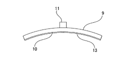
本発明のハニカム型加熱装置1に使用されるヒーター9の数は、複数であればよく、上限数は特に限定されないが、装置の組み立て易さ等を考慮すると、2〜16個程度とすることが好ましい。外周面が湾曲したハニカム基材(例えば円柱状のハニカム基材)を用いる場合には、図7に示すように、ヒーター9に、ハニカム基材の外周面と同程度に湾曲した凹円弧状の面10が形成されていることが好ましい。この凹円弧状の面10は、中間材14を介して、外周面8と対向する面である。このような面10を形成することにより、ヒーター9をハニカム基材2の外周面8上に配置したときに、ヒーター9と外周面8との間に大きな隙間が生じ難くなる。
The number of
また、本発明のハニカム型加熱装置1は、ハニカム基材2の周方向において、外周面8の50%以上がヒーター9により覆われている部分を有していることが好ましい。更に、本発明のハニカム型加熱装置1には、前記のような、「ハニカム基材2の周方向において、外周面8の50%以上がヒーター9により覆われている部分」が、ハニカム基材2の軸方向において、ハニカム基材2の全長の60%以上の長さに渡って存在することが好ましい。ハニカム基材2の外周面8において、ヒーター9により覆われる領域を、このように設定することにより、ハニカム基材2を目標とする温度まで加熱し易くなる。
In addition, the
通常、本発明のハニカム型加熱装置1を、自動車に搭載して使用する場合、ヒーター9の通電に、自動車の電気系統に使用される電源が共通で使用され、例えば200Vという高い電圧の電源が用いられる。このため、本発明のハニカム型加熱装置1において、ヒーター9に、抵抗加熱式ヒーターを用いる場合、複数のヒーター9が、電気的に直列又は並列に接続されており、200V以上の高電圧を通電できるような電気抵抗を有することが好ましい。ここで、「200V以上の高電圧を通電できる」とは、具体的には、200V通電時に電流を25A程度とすることが可能であることを意味する。
Normally, when the
尚、金属製のヒーターは、電気抵抗が低いため、このような高い電圧の電源を用いた場合、過剰に電流が流れ、電源回路を損傷させることがある。よって、本発明のハニカム型加熱装置1においては、セラミック部材の内部に発熱抵抗体が埋設されたセラミックヒーターを用いることが好ましい。セラミック部材の構成材料としては、ベリリア、窒化アルミニウム、窒化珪素、アルミナ等が好適に使用できる。また、発熱抵抗体の構成材料としては、銀(Ag)、アルミニウム(Al)、金(Au)、ベリリウム(Be)、銅(Cu)、マグネシウム(Mg)、モリブデン(Mo)、タングステン(W)、ルテニウム(Ru)、白金(Pt)等が好適に使用できる。また、発熱抵抗体の構成材料は、化合物であってもよく、この場合、ジルコニウム(Zr)、チタニウム(Ti)、ニオブ(Nb)、ハフニウム(Hf)、タンタル(Ta)、モリブデン(Mo)、タングステン(W)の窒化物、炭化物、硼化物、珪化物等が好適に使用できる。
Since the metal heater has a low electric resistance, when such a high voltage power supply is used, an excessive current flows and the power supply circuit may be damaged. Therefore, in the honeycomb
本発明のハニカム型加熱装置1に使用されるヒーター9が抵抗加熱式ヒーターであり、ハニカム基材2が導電性材料から形成されている場合、各ヒーター9は、各ヒーター9からハニカム基材2へ電流が流れるのを防止するための絶縁機能を有することが好ましい。各ヒーター9が絶縁機能を有していると、ハニカム基材2が導電性材料から形成されている場合においても、各ヒーター9からハニカム基材へ電流が流れて、短絡(ショート)するのを防止することができる。各ヒーター9に絶縁機能を付与する方法の一例としては、例えば、図8に示すように、各ヒーター9の、ハニカム基材の外周面と対向する面10に、絶縁材13を配設する方法が挙げられる。絶縁材13の材質としては、窒化珪素、アルミナ等が好適に使用できる。
When the
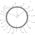
本発明のハニカム型加熱装置1では、ハニカム基材2の長さ方向(軸方向)に直交する断面において、ハニカム基材2の外周面8上に配置されている各ヒーター9の中心角αが、180゜以下であることが好ましい。また、この中心角αは、10〜180゜であることがより好ましく、10〜100゜であることが更に好ましい。ここで、「各ヒーター9の中心角α」とは、図10に示すように、ハニカム基材2の長さ方向に直交する断面において、各ヒーター9の両端とハニカム基材2の中心Oとを結ぶ2本の線分により形成される角である。また、「ハニカム基材2の中心O」とは、図10に示すように、ハニカム基材2の長さ方向に直交する断面の外周形状が円形である場合は、その円の中心を意味する。また、ハニカム基材2の長さ方向に直交する断面の外周形状が円形以外の形状である場合は、その断面に内包される最大の円の中心を意味する。各ヒーター9の中心角αが、180゜を超えると、ハニカム基材2とヒーター9との間に大きな隙間が生じ易くなる。また、各ヒーター9の中心角αが、10゜未満では、1つのヒーター9で覆うことができる外周面8の範囲が狭くなり、ハニカム基材2を目標の温度まで加熱するために必要なヒーター9の数が多くなりすぎる場合がある。尚、図10においては、ハニカム基材2の隔壁が省略されている。
In the honeycomb
本発明のハニカム型加熱装置1に使用されるハニカム基材2は、熱伝導率が20W/m・K以上のセラミック材料で構成されていることが好ましく、熱伝導率が50W/m・K以上のセラミック材料で構成されていることがより好ましい。ハニカム基材2が、このような熱伝導率の高い材料で構成されていることにより、ヒーター9の熱をハニカム基材2に効率良く伝達することができるとともに、ハニカム基材2全体を均一に発熱させることができる。尚、本発明において、ハニカム基材の熱伝導率は、ハニカム基材から、直径5mm×厚さ1mmの円板状の測定用試料を切り出し、JIS R 1611に準拠した方法により測定した値である。
The
ハニカム基材2の構成材料としては、熱伝導性、耐熱性、耐食性に優れたSiC(炭化珪素)を主成分とするものが好ましい。尚、ここで言う「主成分」とは、材料全体の50質量%以上であることを意味する。より具体的な構成材料としては、Si−SiC複合材、(Si+Al)−SiC複合材、金属複合SiC、再結晶SiC、Si3N4、SiC等が好適な材料として挙げられる。但し、ハニカム基材2の気孔率が高すぎる場合には、これらの材料を用いても、高い熱伝導率が得られないことがあるため、ハニカム基材2は緻密質(気孔率が20%以下)であることが好ましい。Si−SiC複合材は、SiCに金属Siが含浸されることで緻密に形成され、高い熱伝導率や耐熱性を示すため、ハニカム基材2の構成材料として特に好ましい。
As a constituent material of the
ハニカム基材2の外周壁3の厚さは、隔壁4の厚さよりも厚いことが好ましい。このように、外周壁3の厚さを、隔壁4の厚さよりも厚くすることで、ハニカム基材2の強度を高めることができ、ハニカム基材2に必要な強度を確保し易くなる。
The thickness of the outer
ハニカム基材2の外周壁3の厚さは、特に制限はないが、0.15〜2.0mmとすることが好ましく、0.3〜1.0mmとすることが更に好ましい。外周壁3の厚さを0.15mm以上とすることにより、ハニカム基材2の械的強度を十分なものとし、衝撃や熱応力によってハニカム基材2が破損するのを防止することができる。また、外周壁3の厚さを2.0mm以下とすることにより、ヒーター9の熱を外周壁3を介して隔壁4まで効率良く伝達できる。
The thickness of the outer
ハニカム基材2の隔壁4の厚さも、特に制限はないが、0.1〜1mmとすることが好ましく、0.2〜0.5mmとすることが更に好ましい。隔壁4の厚さを0.1mm以上とすることにより、ハニカム基材2の機械的強度を十分なものとし、衝撃や熱応力によってハニカム基材2が破損するのを防止することができる。また、隔壁4の厚さを1mm以下とすることにより、流体がセル5内を流れる際の圧力損失が大きくなるのを防止することができる。
The thickness of the
ハニカム基材2のセル密度(単位断面積当たりのセルの数)については特に制限はないが、25〜2000セル/平方インチ(4〜320セル/cm2)の範囲であることが好ましい。セル密度を25セル/平方インチ(4セル/cm2)以上とすることにより、隔壁4の強度、ひいてはハニカム基材2自体の強度及び有効GSA(幾何学的表面積)を十分なものとすることができる。また、セル密度を2000セル/平方インチ(320セル/cm2)以下とすることにより、流体がセル5内を流れる際の圧力損失が大きくなるのを防止することができる。
The cell density of the honeycomb substrate 2 (the number of cells per unit cross-sectional area) is not particularly limited, but is preferably in the range of 25 to 2000 cells / in 2 (4 to 320 cells / cm 2 ). By setting the cell density to 25 cells / in 2 (4 cells / cm 2 ) or more, the strength of the
ハニカム基材2の気孔率は、20%以下であることが好ましく、10%以下であることがより好ましい。ハニカム基材2の気孔率をこのような範囲とすることにより、ハニカム基材2に必要な強度を確保し易くなるとともに、高い熱伝導率を発現させ易くなる。尚、本発明において、ハニカム基材の気孔率は、アルキメデス法により測定した値である。
The porosity of the
ハニカム基材2の形状(外形)は、柱状であること以外は特に限定されず、例えば、円柱状、楕円柱状、多角柱状等の形状とすることができる。また、セル5のハニカム基材2の長さ方向に対して垂直な断面における形状(以下、「セル形状」という。)も特に限定されないが、四角形、六角形、八角形等の多角形あるいはそれらを組み合わせたもの、例えば四角形と八角形を組み合わせたもの等が好ましい。
The shape (outer shape) of the
ハニカム基材2の長さ方向に垂直な断面の直径(当該断面が円形以外の形状である場合は、当該断面に外接する円の直径)は、特に限定されるものではないが、300mm以下であることが好ましく、200mm以下であることがより好ましい。ハニカム基材2の長さ方向に垂直な断面の直径を、このような範囲とすることにより、ヒーター9の熱を、ハニカム基材2の内部の隔壁4まで、効率良く伝達することができる。
The diameter of the cross section perpendicular to the length direction of the honeycomb substrate 2 (when the cross section is a shape other than a circle, the diameter of a circle circumscribing the cross section) is not particularly limited, but is 300 mm or less. It is preferable that it is 200 mm or less. By setting the diameter of the cross section perpendicular to the length direction of the
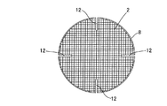
ハニカム基材2には、ストレスレリーフ(stress relief)が形成されていることが好ましい。ストレスレリーフを形成することにより、ハニカム基材2内での応力緩和が可能となる。ストレスレリーフの代表的なものとしては、例えば、図9に示すように、ハニカム基材2の外周面8から内部方向に切り込まれたスリット12が挙げられる。但し、ストレスレリーフは、このようなスリット12に限定されるものではなく、本発明を逸脱しない範囲で公知のストレスレリーフを形成することができる。
The
本発明のハニカム型加熱装置1を、エンジンから排出される排ガスの排気経路に設置して使用する場合、ハニカム基材2の隔壁4に排ガス浄化用の触媒を担持させることが好ましい。このように隔壁4に触媒を担持させると、排ガス中のCO、NOx、HC等の有害物質を、触媒反応によって無害な物質にすることが可能になる。ここで、ハニカム基材2の隔壁4に担持させる触媒の種類は特に限定されないが、例えば、自動車排ガス浄化用途に用いる場合、貴金属を用いることが好ましい。貴金属としては、白金、ロジウム若しくはパラジウム、又はこれらを組み合わせたものが好ましい。これら貴金属の担持量は、ハニカム基材2の単位体積当たり、0.1〜5g/Lとすることが好ましい。
When the
貴金属等の触媒は、隔壁4に高分散状態で担持させるため、一旦、アルミナ等の比表面積の大きな耐熱性無機酸化物の粒子(担体微粒子)に担持させた後、その粒子とともにハニカム基材2の隔壁4に担持させることが好ましい。
Since the catalyst such as a noble metal is supported on the
本発明のハニカム型加熱装置1の用途や使用形態は、特に限定されるものではないが、エンジンから排出される排ガスの排気経路に設置して使用することが、その効果を有効に活用する観点から好ましい。そして、その場合、本発明のハニカム型加熱装置1は、エンジンの始動前に各ヒーター9を発熱させて、排ガス浄化用の触媒を担持させたハニカム基材2を、その触媒の触媒活性温度以上の温度に昇温させるために使用することが好ましい。本発明のハニカム型加熱装置1を、このように使用すると、エンジン始動直後から、活性化した触媒により、排ガス中に含まれる有害成分を効率良く浄化することができる。
The application and use form of the honeycomb
(2)キャニング済みハニカム型加熱装置:
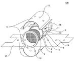
図4は、本発明のキャニング済みハニカム型加熱装置の実施形態の一例を示す概略分解図である。また、図5は、本発明のキャニング済みハニカム型加熱装置の実施形態の一例を、当該装置の長さ方向(軸方向)に垂直な断面で示す概略断面図であり、図6は、本発明のキャニング済みハニカム型加熱装置の実施形態の一例を、当該装置の長さ方向(軸方向)に平行な断面で示す概略断面図である。これら図4〜6に示すように、本発明のキャニング済みハニカム型加熱装置100は、本発明のハニカム型加熱装置1が、筒状のキャニングケース15に収容されたものである。
(2) Canned honeycomb heating device:
FIG. 4 is a schematic exploded view showing an example of an embodiment of the canned honeycomb heating apparatus of the present invention. FIG. 5 is a schematic cross-sectional view showing an example of an embodiment of the canned honeycomb-type heating device of the present invention in a cross section perpendicular to the length direction (axial direction) of the device, and FIG. It is a schematic sectional drawing which shows an example of embodiment of this canned honeycomb type heating apparatus with the cross section parallel to the length direction (axial direction) of the said apparatus. As shown in FIGS. 4 to 6, a canned
通常、排ガスの排気経路において使用する加熱装置は、筒状のキャニングケース15に収容された状態で設置される。本発明のキャニング済みハニカム型加熱装置100においては、本発明のハニカム型加熱装置1が既にキャニングケース15内に収納されているため、そのまま排ガスの排気経路に設置して使用することができる。
Usually, the heating device used in the exhaust gas exhaust path is installed in a state where it is accommodated in a
キャニングケースの構造は特に限定されないが、図4に示す実施形態では、ハニカム基材2の収納を容易にするため、クラムシェル構造のキャニングケース15が使用されている。このクラムシェル構造のキャニングケース15は、半円状に湾曲した部位を有する2つの部材から構成され、それらを組み合わせて結合することにより筒状となる。このキャニングケース15には、ヒーター9の電極端子突起部11をキャニングケース15の外部に突出させるための孔18が形成されていることが好ましい。この孔18を通じて、ヒーター9の電極端子突起部11をキャニングケース15の外部に突出させることにより、ヒーター9に通電するための電気配線の結線を、キャニングケース15の外部で行うことができる。尚、電極端子突起部11とキャニングケース15とを絶縁するため、電極端子突起部11には、その外周面を覆うことができるキャップ状の絶縁部材が装着されていることが好ましい。
The structure of the canning case is not particularly limited, but in the embodiment shown in FIG. 4, a
本発明のキャニング済みハニカム型加熱装置100においては、図6に示すように、キャニングケース15内において、ハニカム基材2の両端面にそれぞれ近接するようにリテナーリング(retainer ring)16を配設することが好ましい。このように、リテナーリング16を配設することによって、振動によるハニカム基材2の位置ずれを防止することができる。更に、このリテナーリング16によって、キャニングケース15と、ハニカム基材2と、リテナーリング16とにより区画形成される空間20内への流体の流入が防止される。その結果、本発明のハニカム型加熱装置1を、エンジンから排出される排ガスの排気経路に設置して使用する場合に、排ガスに含まれる凝縮水(水蒸気)にヒーター9が暴露されることを防止でき、ヒーターが劣化し難くなる。
In the canned
また、キャニング済みハニカム型加熱装置100においては、図4〜6に示すように、各ヒーター9とキャニングケース15との間に断熱材17を配設することが好ましい。このように、断熱材17を配設することによって、ヒーター9の熱が外部に逃げ難くなり、ヒーター9の熱を、ハニカム基材2に効率良く伝達することができる。断熱材17の材質は特に限定されないが、ハニカム基材2の外周に巻き付けることによって、各ヒーター9とキャニングケース15との間に容易に配設でき、断熱性も高いことから、セラミック繊維マットを用いることが好ましい。断熱材17を、ヒーター9を含めたハニカム基材2の外周全体に巻き付ける場合には、図4〜6に示すように、断熱材17にも、ヒーター9の電極端子突起部11をキャニングケース15の外部に突出させるための孔19を形成することが好ましい。
Moreover, in the canned
(3)ハニカム型加熱装置の製造方法:
本発明のハニカム型加熱装置の製造方法は、上述した本発明のハニカム型加熱装置1を製造する方法の一例である。即ち、この製造方法において製造するハニカム型加熱装置1は、図1〜3に示すように、ハニカム基材2、複数のヒーター9及び中間材14を備えるものである。ハニカム基材2は、柱状で、一方の端面6から他方の端面7まで延びる複数のセル5を区画形成する隔壁4と、隔壁4を取り囲む外周壁3とを有する。セル5は、排ガス等の流体の流路となる。複数のヒーター9は、ハニカム基材2の外周壁3の外側表面である外周面8の周方向に沿って、外周面8上に隣接配置されている。中間材14は、ハニカム基材2の外周面8と複数のヒーター9との間に挟み込まれた状態で配置されている。中間材14は、少なくともその一部が、1W/m・K以上の熱伝導率を有することが好ましい。また、このハニカム型加熱装置1では、ハニカム基材2の外周面8と複数のヒーター9との間において中間材14が外周面8を覆っている部分の面積の合計が、複数のヒーター9が外周面8を覆っている部分の面積の合計の20〜100%である。本発明のハニカム型加熱装置の製造方法においては、このようなハニカム型加熱装置1を、以下に説明する「ペースト塗布工程」と「ヒーター配置工程」と「中間材形成工程」とを含む方法によって製造する。尚、ハニカム基材に排ガス浄化用の触媒が担持されたハニカム型加熱装置を製造する場合には、前記工程に、更に後述する「触媒担持工程」を加えた製造方法を用いることが好ましい。
(3) Manufacturing method of honeycomb heating device:
The manufacturing method of the honeycomb type heating apparatus of the present invention is an example of a method of manufacturing the above-described honeycomb
(3−1)ペースト塗布工程:
この工程においては、ハニカム基材2の外周面8の各ヒーター9が配置される部位、又は各ヒーター9のハニカム基材2の外周面8と対向する面に、SiC粒子とコロイダルシリカとを含む中間材形成用のペーストを塗布する。あるいは、ハニカム基材2の外周面8の各ヒーター9が配置される部位と、各ヒーター9のハニカム基材2の外周面8と対向する面との両方に、SiC粒子とコロイダルシリカとを含む中間材形成用のペーストを塗布してもよい。このペーストには、乾燥後の熱伝導率が1W/m・K以上となるものを用いることが好ましい。このようなペーストは、例えば、SiC粒子とコロイダルシリカに含まれるシリカとの質量比(SiC粒子の質量:シリカの質量)が、30:70〜80:20程度となるように、SiC粒子とコロイダルシリカとを配合することにより得られる。尚、前記ペースト中に金属Si等の熱伝導率の高い材料からなる粒子を添加して、乾燥後の熱伝導率を調整してもよい。
(3-1) Paste application process:
In this step, SiC particles and colloidal silica are included in the portion of the outer
(3−2)ヒーター配置工程:
この工程は、前記ペースト塗布工程後に行われる。この工程においては、複数のヒーター9を、ハニカム基材2の外周面8の周方向に沿って、外周面8上に隣接配置する。複数のヒーター9は、前記ペースト塗布工程で塗布されたペーストを挟んだ状態で、外周面8上に配置される。
(3-2) Heater arrangement process:
This step is performed after the paste application step. In this step, a plurality of
(3−3)中間材形成工程:
この工程は、前記ヒーター配置工程後に行われる。この工程においては、ハニカム基材2の外周面8と、複数のヒーター9との間に挟まれた前記ペーストを加熱して乾燥させる。こうして前記ペーストを乾燥(固化)させることにより、前記ペーストから中間材14が形成される。ペーストを乾燥させる際の加熱温度は、600℃を超えない温度、例えば、400〜600℃程度とすることが好ましい。このような温度で加熱すれば、後述する触媒担持工程において、予めハニカム基材に排ガス浄化用の触媒が担持されていても、加熱による当該触媒の熱劣化を防止することができる。
(3-3) Intermediate material forming step:
This step is performed after the heater placement step. In this step, the paste sandwiched between the outer
(3−4)触媒担持工程:
この工程は、ハニカム基材2に排ガス浄化用の触媒が担持されたハニカム型加熱装置1を製造する場合において、前記ペースト塗布工程の前に行われる。この工程においては、ハニカム基材2の隔壁4に、排ガス浄化用の触媒を担持させる。具体的な担持方法としては、例えば、予め、担体微粒子となるセラミックス粉末に、貴金属等の触媒成分を含む水溶液を含浸させた後、乾燥し、焼成することにより触媒コート微粒子を得る。こうして得られた触媒コート微粒子に、分散媒(水等)、その他の添加剤を加えてコーティング液(スラリー)を調製する。そして、このスラリーを、吸引法等の従来公知のコーティング方法を用いて、ハニカム基材2の隔壁4にコーティングした後、乾燥し、焼成することによって、ハニカム基材2の隔壁4に触媒を担持させる。
(3-4) Catalyst supporting step:
This step is performed before the paste coating step in the case of manufacturing the
以上の工程を含む製造方法により、本発明のハニカム型加熱装置1を製造することができる。
With the manufacturing method including the above steps, the
尚、本発明のハニカム型加熱装置の製造方法において、ハニカム型加熱装置の構成要素として使用されるハニカム基材は、例えば、以下のようにして作製することができる。まず、ハニカム基材を作製するために、セラミック原料を含有する成形原料を作製する。セラミック原料には、先にハニカム基材の材料として例示したセラミックスを形成できるような粉末を好適に使用することができる。例えば、ハニカム基材の構成材料として、Si−SiC複合材を採用する場合には、SiC粉末をセラミック原料とすることが好ましい。成形原料は、このようなセラミック原料に、必要に応じて、分散媒、有機バインダ、無機バインダ、界面活性剤等の添加剤を混合して調製することが好ましい。 In the method for manufacturing a honeycomb type heating apparatus of the present invention, a honeycomb substrate used as a component of the honeycomb type heating apparatus can be manufactured, for example, as follows. First, in order to produce a honeycomb substrate, a forming raw material containing a ceramic raw material is produced. As the ceramic raw material, a powder capable of forming the ceramics exemplified above as the material for the honeycomb substrate can be preferably used. For example, when a Si—SiC composite material is employed as the constituent material of the honeycomb substrate, it is preferable to use SiC powder as a ceramic raw material. The forming raw material is preferably prepared by mixing such a ceramic raw material with additives such as a dispersion medium, an organic binder, an inorganic binder, and a surfactant as necessary.
次に、成形原料を混練して柱状の坏土を形成する。成形原料を混練して坏土を形成する方法には、特に制限はない。好適な方法としては、例えば、ニーダー、真空土練機等を用いる方法を挙げることができる。 Next, the forming raw material is kneaded to form a columnar clay. There is no particular limitation on the method of kneading the forming raw material to form the clay. Suitable methods include, for example, a method using a kneader, a vacuum kneader or the like.
次いで、格子状のスリットが形成された口金を用いて、坏土から、隔壁と外周壁とを有するハニカム成形体を押出成形し、このハニカム成形体を乾燥する。乾燥方法は、特に限定されるものではない。好適な乾燥方法としては、例えば、熱風乾燥、マイクロ波乾燥、誘電乾燥、減圧乾燥、真空乾燥、凍結乾燥等を挙げることができる。これらの内でも、誘電乾燥、マイクロ波乾燥、熱風乾燥を単独で又は組合せて行うことが好ましい。 Next, a honeycomb formed body having partition walls and an outer peripheral wall is extruded from the clay using a die in which lattice-shaped slits are formed, and the honeycomb formed body is dried. The drying method is not particularly limited. Suitable drying methods include, for example, hot air drying, microwave drying, dielectric drying, reduced pressure drying, vacuum drying, freeze drying and the like. Among these, dielectric drying, microwave drying, and hot air drying are preferably performed alone or in combination.
続いて、乾燥後のハニカム成形体(ハニカム乾燥体)を焼成して、ハニカム基材を作製する。尚、この焼成(本焼成)の前に、ハニカム成形体中に含まれているバインダ等を除去するため、仮焼(脱脂)を行うことが好ましい。仮焼の条件は、特に限定されるものではなく、ハニカム成形体中に含まれている有機物(有機バインダ等)を除去(燃焼)することができるような条件あればよい。ハニカム成形体を焼成(本焼成)する条件(温度、時間、雰囲気等)は、成形原料の種類により異なるため、その種類に応じて適当な条件を選択すればよい。例えば、Si−SiC複合材から構成されるハニカム基材を作製する場合は、SiC粉末を含むハニカム成形体上に、塊状の金属Siを載置して、減圧の不活性ガス又は真空中で焼成し、金属Siをハニカム成形体に含浸させる。この焼成により、SiC粒子の隙間に金属Siが充填された緻密質(低気孔率)のハニカム基材が得られる。尚、ハニカム基材には、必要に応じて、スリット等のストレスレリーフを形成してもよい。 Subsequently, the dried honeycomb formed body (honeycomb dried body) is fired to produce a honeycomb substrate. In addition, before this firing (main firing), it is preferable to perform calcination (degreasing) in order to remove the binder and the like contained in the honeycomb formed body. The conditions for the calcination are not particularly limited as long as the organic substances (such as an organic binder) contained in the honeycomb formed body can be removed (burned). Since the conditions (temperature, time, atmosphere, etc.) for firing (main firing) the honeycomb formed body vary depending on the type of the forming raw material, an appropriate condition may be selected according to the type. For example, when producing a honeycomb base material composed of a Si-SiC composite material, massive metal Si is placed on a honeycomb formed body containing SiC powder and fired in a vacuum inert gas or in vacuum. Then, the honeycomb formed body is impregnated with metal Si. By this firing, a dense (low porosity) honeycomb base material in which metal Si is filled in the gaps between the SiC particles is obtained. In addition, you may form stress reliefs, such as a slit, in a honeycomb base material as needed.
また、本発明のハニカム型加熱装置の製造方法において、ハニカム型加熱装置の構成要素として使用されるヒーターは、例えば、以下のようにして作製することができる。尚、以下に説明する作製方法は、抵抗加熱式ヒーターの一種であるセラミックヒーターを作製する方法の一例である。まず、窒化アルミニウム、窒化珪素、アルミナ等のセラミック原料に、適宜、焼結助剤、バインダ等を添加して成形原料を得る。この成形原料に、発熱抵抗体を埋没させ、プレス成形等により、例えば、ハニカム基材の外周面と同程度に湾曲した凹円弧状の面と、その凹円弧状の面と反対側の面に筒状の電極端子突起部とを有する成形体を得る。尚、成形は、発熱抵抗体の端部(電極端子)が、筒状の電極端子突起部内に露出するように位置調整して行う。発熱抵抗体としては、銀(Ag)、アルミニウム(Al)、金(Au)、ベリリウム(Be)、銅(Cu)、マグネシウム(Mg)、モリブデン(Mo)、タングステン(W)、ルテニウム(Ru)、白金(Pt)等からなるものが好適に使用できる。また、発熱抵抗体は、化合物からなるものであってもよく、この場合、ジルコニウム(Zr)、チタニウム(Ti)、ニオブ(Nb)、ハフニウム(Hf)、タンタル(Ta)、モリブデン(Mo)、タングステン(W)の窒化物、炭化物、硼化物、珪化物等からなるものが好適に使用できる。こうして得られた成形体を、必要に応じて、乾燥、仮焼した後、焼成し、セラミック部材の内部に発熱抵抗体が埋設されたセラミックヒーターを得る。尚、セラミックヒーターの凹円弧状の面には、必要に応じ、窒化珪素、アルミナ等からなる絶縁材を配設してもよい。 In addition, in the method for manufacturing a honeycomb type heating device of the present invention, a heater used as a component of the honeycomb type heating device can be manufactured as follows, for example. Note that the manufacturing method described below is an example of a method for manufacturing a ceramic heater which is a kind of resistance heating heater. First, a forming raw material is obtained by appropriately adding a sintering aid, a binder or the like to a ceramic raw material such as aluminum nitride, silicon nitride, or alumina. In this forming raw material, a heating resistor is buried, and, for example, by pressing, a concave arc-shaped surface curved to the same extent as the outer peripheral surface of the honeycomb substrate and a surface opposite to the concave arc-shaped surface are formed. A molded body having a cylindrical electrode terminal protrusion is obtained. In addition, shaping | molding performs position adjustment so that the edge part (electrode terminal) of a heating resistor may be exposed in a cylindrical electrode terminal protrusion part. As the heating resistor, silver (Ag), aluminum (Al), gold (Au), beryllium (Be), copper (Cu), magnesium (Mg), molybdenum (Mo), tungsten (W), ruthenium (Ru) , Platinum (Pt) or the like can be preferably used. The heating resistor may be made of a compound. In this case, zirconium (Zr), titanium (Ti), niobium (Nb), hafnium (Hf), tantalum (Ta), molybdenum (Mo), A tungsten (W) nitride, carbide, boride, silicide, or the like can be suitably used. The molded body thus obtained is dried and calcined as necessary, and then fired to obtain a ceramic heater in which a heating resistor is embedded in the ceramic member. Note that an insulating material made of silicon nitride, alumina, or the like may be provided on the concave arc-shaped surface of the ceramic heater, if necessary.
(4)キャニング済みハニカム型加熱装置の製造方法:
図4〜6に示すような、キャニング済みハニカム型加熱装置1を製造する方法の一例としては、まず、本発明のハニカム型加熱装置の製造方法により得られたハニカム型加熱装置1の外周に、セラミック繊維マット(断熱材17)を巻き付ける。次いで、ハニカム基材2の両端面にそれぞれ近接するようにリテナーリング16を配置する。そして、それらを、クラムシェル構造のキャニングケース15を構成する、半円状に湾曲した部位を有する2つの部材で挟み込み、その2つの部材を結合させる。このような方法により、ハニカム型加熱装置1が筒状のキャニングケース15に収納された、本発明のキャニング済みハニカム型加熱装置が得られる。
(4) Manufacturing method of canned honeycomb heating device:
As an example of a method for manufacturing the canned
(5)ハニカム型加熱装置の使用方法:
本発明のハニカム型加熱装置の使用方法において使用されるハニカム型加熱装置は、上述した本発明のハニカム型加熱装置である。即ち、当該使用方法においては、図1〜3に示すような、ハニカム基材2、複数のヒーター9及び中間材14を備えるハニカム型加熱装置1が使用される。このハニカム型加熱装置1において、ハニカム基材2は、柱状で、一方の端面6から他方の端面7まで延びる複数のセル5を区画形成する隔壁4と、隔壁4を取り囲む外周壁3とを有する。セル5は、排ガス等の流体の流路となる。複数のヒーター9は、ハニカム基材2の外周壁3の外側表面である外周面8の周方向に沿って、外周面8上に隣接配置されている。ハニカム基材2には、排ガス浄化用の触媒が担持されている。中間材14は、ハニカム基材2の外周面8と複数のヒーター9との間に挟み込まれた状態で配置されている。中間材14は、少なくともその一部が、1W/m・K以上の熱伝導率を有することが好ましい。また、このハニカム型加熱装置1では、ハニカム基材2の外周面8と複数のヒーター9との間において中間材14が外周面8を覆っている部分の面積の合計が、複数のヒーター9が外周面8を覆っている部分の面積の合計の20〜100%である。尚、このハニカム型加熱装置1の詳細は、上述のとおりである。
(5) How to use the honeycomb type heating device:
The honeycomb type heating device used in the method of using the honeycomb type heating device of the present invention is the above-described honeycomb type heating device of the present invention. That is, in the usage method, a
本発明のハニカム型加熱装置の使用方法においては、このようなハニカム型加熱装置1を、エンジンから排出される排ガスの排気経路に設置する。そして、エンジンの始動前に各ヒーター9を発熱させて、排ガス浄化用の触媒を担持させたハニカム基材2を、触媒の触媒活性温度以上の温度に昇温させる。
In the method for using the honeycomb type heating apparatus of the present invention, such a honeycomb
このような本発明のハニカム型加熱装置の使用方法により、エンジン始動直後から、活性化した触媒により、排ガス中に含まれる有害成分を効率良く浄化することが可能となる。 With such a method of using the honeycomb heating apparatus of the present invention, it becomes possible to efficiently purify harmful components contained in the exhaust gas with the activated catalyst immediately after starting the engine.
以下、本発明を実施例に基づいて更に詳細に説明するが、本発明はこれらの実施例に限定されるものではない。 EXAMPLES Hereinafter, although this invention is demonstrated further in detail based on an Example, this invention is not limited to these Examples.
(実施例1)
SiC粉末に、バインダ及び水を加えてハニカム基材用成形原料を作製し、それを真空土練機で混練して、円柱状の坏土を得た。この坏土から、押出成形により、一方の端面から他方の端面まで延びる複数のセルを区画形成する隔壁と、その隔壁を取り囲む外周壁とを有する円柱状のハニカム成形体を得た。その後、このハニカム成形体をマイクロ波及び熱風で乾燥することにより、ハニカム乾燥体を得た。次いで、このハニカム乾燥体上に、塊状の金属Siを載置し、真空炉中で焼成し、Si−SiC複合材から構成されたハニカム基材を得た。こうして得られたハニカム基材は、直径が93mm、長さが75mmの円柱状で、外周壁の厚さは2mm、隔壁の厚さは0.15mm(6mil)、セル形状は正六角形、セル密度は64セル/cm2(400セル/平方インチ)であった。また、このハニカム基材は、熱伝導率が150W/m・K、ヤング率が300GPa、熱膨張係数が4.2×10−6/℃であった。
Example 1
A binder and water were added to the SiC powder to prepare a forming material for a honeycomb substrate, which was kneaded with a vacuum kneader to obtain a cylindrical clay. From this kneaded material, a columnar honeycomb formed body having partition walls for partitioning a plurality of cells extending from one end face to the other end face and an outer peripheral wall surrounding the partition walls was obtained by extrusion molding. Thereafter, this honeycomb formed body was dried with microwaves and hot air to obtain a dried honeycomb body. Next, massive metal Si was placed on the dried honeycomb body and fired in a vacuum furnace to obtain a honeycomb substrate made of a Si—SiC composite material. The honeycomb substrate thus obtained has a columnar shape with a diameter of 93 mm and a length of 75 mm, an outer peripheral wall thickness of 2 mm, a partition wall thickness of 0.15 mm (6 mil), a cell shape of regular hexagon, and a cell density. Was 64 cells / cm 2 (400 cells / in 2 ). The honeycomb substrate had a thermal conductivity of 150 W / m · K, a Young's modulus of 300 GPa, and a thermal expansion coefficient of 4.2 × 10 −6 / ° C.
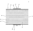
次に、Si3N4粉末に、バインダ及び水を加えてヒーター用成形原料を作製した。このヒーター用成形原料からハニカム基材の外周面と同程度に湾曲したプレート成形体を作製し焼成することで、Si3N4からなるセラミックプレートを作製した。そのセラミックプレートに、白金からなる発熱抵抗体を印刷した後に再度焼成し、発熱抵抗体の上にSi3N4からなるセラミックプレートを積層し接着することで、凹円弧状の面を有する抵抗加熱式のヒーター(セラミックヒーター)を得た。このヒーターの凹円弧状の面は、幅(円弧部分の長さ)が30mm、長さ(円弧部分に垂直な方向の長さ)が65mmであった。 Next, a binder and water were added to the Si 3 N 4 powder to produce a heater forming raw material. A ceramic plate made of Si 3 N 4 was produced by producing and firing a plate molded body curved to the same extent as the outer peripheral surface of the honeycomb base material from the forming raw material for heater. A heating resistor made of platinum is printed on the ceramic plate and then fired again, and a ceramic plate made of Si 3 N 4 is laminated on the heating resistor and bonded to form a resistive heating having a concave arc surface. A heater of the formula (ceramic heater) was obtained. The concave arc-shaped surface of this heater had a width (length of the arc portion) of 30 mm and a length (length in a direction perpendicular to the arc portion) of 65 mm.
次いで、平均粒径が20μmのSiC粒子とコロイダルシリカとを、SiC粒子とコロイダルシリカに含まれるシリカとの質量比(SiC粒子の質量:シリカの質量)が、30:70となるように配合して、中間材形成用ペーストを作製した。 Next, SiC particles having an average particle diameter of 20 μm and colloidal silica are blended so that the mass ratio of SiC particles to silica contained in the colloidal silica (the mass of SiC particles: the mass of silica) is 30:70. Thus, an intermediate material forming paste was prepared.
続いて、ハニカム基材の外周面の各ヒーターが配置される部位に、中間材形成用ペーストを塗布した。その後、前記のようにして得られた8個のヒーターを、この中間材形成用ペーストを挟むようにして、ハニカム基材の外周面上に配置した。これらのヒーターは、ハニカム基材の外周面の周方向に沿って隣接配置した。このとき、ハニカム基材の外周面の周方向において、隣接するヒーター間の間隔が全て等しくなるようにヒーターの位置を調整した。このように、中間材形成用ペーストを介して、ヒーターが外周面上に配置されたハニカム基材を、大気中、600℃で加熱して、中間材形成用ペーストを乾燥(固化)させることにより、中間材を形成した。 Subsequently, the intermediate material forming paste was applied to the portion of the outer peripheral surface of the honeycomb substrate where the heaters are arranged. Thereafter, the eight heaters obtained as described above were arranged on the outer peripheral surface of the honeycomb substrate so as to sandwich the intermediate material forming paste. These heaters were arranged adjacent to each other along the circumferential direction of the outer peripheral surface of the honeycomb substrate. At this time, the position of the heater was adjusted so that all the intervals between adjacent heaters were equal in the circumferential direction of the outer peripheral surface of the honeycomb substrate. Thus, the intermediate material forming paste is dried (solidified) by heating the honeycomb substrate on which the heater is disposed on the outer peripheral surface through the intermediate material forming paste at 600 ° C. in the atmosphere. An intermediate material was formed.
こうして得られたハニカム型加熱装置の中間材は、熱伝導率が0.1W/m・K、ヤング率が0.1GPa、気孔率が30%、熱膨張係数が4.2×10−6/℃で、厚さが500μmであった。また、各ヒーターの中心角は37゜で、ヒーター設置面積に対する中間材設置面積の割合は30%であった。 The intermediate material of the honeycomb type heating device thus obtained has a thermal conductivity of 0.1 W / m · K, a Young's modulus of 0.1 GPa, a porosity of 30%, and a thermal expansion coefficient of 4.2 × 10 −6 / The thickness was 500 μm at ° C. The central angle of each heater was 37 °, and the ratio of the intermediate material installation area to the heater installation area was 30%.
このハニカム型加熱装置のハニカム基材の外周に、セラミック繊維マット(断熱材)を巻き付けるとともに、ハニカム基材の両端面にそれぞれ近接するようにリテナーリングを配置した。そして、それらを、クラムシェル構造のキャニングケースを構成する、半円状に湾曲した部位を有する2つの部材で挟み込み、その2つの部材を結合させて、キャニングケース内に収納し、キャニング済みハニカム型加熱装置を得た。 A ceramic fiber mat (heat insulating material) was wound around the outer periphery of the honeycomb substrate of the honeycomb heating apparatus, and retainer rings were arranged so as to be close to both end faces of the honeycomb substrate. Then, they are sandwiched between two members having a semicircularly curved portion constituting a clamshell structure canning case, and the two members are combined and stored in the canning case. A heating device was obtained.
(評価)
得られたキャニング済みハニカム型加熱装置について、下記の方法により、基材中心温度及び基材平均温度を測定するとともに、耐熱衝撃性試験を実施した。
(Evaluation)
About the obtained canned honeycomb-type heating device, the substrate center temperature and the substrate average temperature were measured by the following method, and a thermal shock resistance test was performed.
[基材中心温度及び基材平均温度]
得られたキャニング済みハニカム型加熱装置の各ヒーター間を結線して直列に接続し、それらヒーターへの投入熱量が300kJとなるように通電した。そして、この通電によるヒーターの発熱によって加熱されたハニカム基材の長さ方向(軸方向)の中央部において、外周壁近傍部分と、軸心部分との温度を測定した。こうして測定された外周壁近傍部分の温度と軸心部分の温度との内、軸心部分の温度を「基材中心温度」として、表2に示した。また、外周壁近傍部分の温度と軸心部分の温度との平均温度を算出し、その値を「基材平均温度」として、表2に示した。
[Substrate center temperature and substrate average temperature]
The heaters of the obtained canned honeycomb heating apparatus were connected and connected in series, and energized so that the amount of heat input to these heaters was 300 kJ. And the temperature of the peripheral wall vicinity part and the axial center part was measured in the center part of the length direction (axial direction) of the honeycomb base material heated by heat_generation | fever of the heater by this electricity supply. Of the temperatures in the vicinity of the outer peripheral wall and the temperature of the shaft center portion measured in this way, the temperature of the shaft center portion is shown as “base material center temperature” and shown in Table 2. Further, an average temperature of the temperature in the vicinity of the outer peripheral wall and the temperature in the axial center portion was calculated, and the value is shown in Table 2 as “base material average temperature”.
[耐熱衝撃性試験(バーナー試験)]
キャニング済みハニカム型加熱装置のキャニングケース内に加熱ガスを供給することができるプロパンガスバーナーを備えたプロパンガスバーナー試験機を用いて、ハニカム型加熱装置の加熱冷却試験を実施した。上記加熱ガスは、ガスバーナー(プロパンガスバーナー)でプロパンガスを燃焼させることにより発生する燃焼ガスとした。そして、上記加熱冷却試験によって、ハニカム型加熱装置のハニカム基材にクラックが発生するか否かを確認することにより、耐熱衝撃性を評価した。具体的には、キャニング済みハニカム型加熱装置のキャニングケース内にプロパンガスバーナーにより加熱されたガス(燃焼ガス)を供給し、ハニカム基材内を通過するようにした。キャニングケースに流入する加熱ガスの温度条件(入口ガス温度条件)を以下のようにした。まず、5分で指定温度まで昇温し、指定温度で10分間保持し、その後、5分で100℃まで冷却し、100℃で10分間保持した。このような昇温、冷却、保持の一連の操作を「昇温、冷却操作」と称する。こ「昇温、冷却操作」の後、ハニカム基材にクラックが発生しているかどうかを調べた。そして、指定温度を825℃から25℃ずつ上昇させながら上記「昇温、冷却操作」を繰り返し、ハニカム基材にクラックが発生したことが確認されたときの指定温度を、「耐熱衝撃性」として、表2に示した。
[Thermal shock resistance test (burner test)]
A heating / cooling test of the honeycomb heating apparatus was performed using a propane gas burner testing machine equipped with a propane gas burner capable of supplying a heating gas into the canning case of the canned honeycomb heating apparatus. The heated gas was a combustion gas generated by burning propane gas with a gas burner (propane gas burner). Then, the thermal shock resistance was evaluated by confirming whether or not cracks occurred in the honeycomb substrate of the honeycomb heating apparatus by the heating and cooling test. Specifically, a gas (combustion gas) heated by a propane gas burner was supplied into a canning case of a canned honeycomb heating apparatus so as to pass through the honeycomb substrate. The temperature condition of the heated gas flowing into the canning case (inlet gas temperature condition) was as follows. First, the temperature was raised to a specified temperature in 5 minutes, held at the specified temperature for 10 minutes, then cooled to 100 ° C. in 5 minutes, and held at 100 ° C. for 10 minutes. Such a series of operations of raising temperature, cooling and holding is referred to as “temperature raising and cooling operation”. After this “temperature increase and cooling operation”, it was examined whether cracks occurred in the honeycomb substrate. Then, the above-mentioned “temperature increase and cooling operation” is repeated while increasing the specified temperature from 825 ° C. in increments of 25 ° C., and the specified temperature when cracks are confirmed to occur in the honeycomb substrate is defined as “thermal shock resistance”. The results are shown in Table 2.
(比較例1)
中間材を形成しなかった以外は実施例1と同様にして、比較例1のキャニング済みハニカム型加熱装置を得た。この比較例1のキャニング済みハニカム型加熱装置について、実施例1のキャニング済みハニカム型加熱装置と同様に、基材中心温度及び基材平均温度を測定するとともに、耐熱衝撃性試験を実施した。
(Comparative Example 1)
A canned honeycomb heating device of Comparative Example 1 was obtained in the same manner as Example 1 except that no intermediate material was formed. For the canned honeycomb type heating device of Comparative Example 1, as with the canned honeycomb type heating device of Example 1, the substrate center temperature and the substrate average temperature were measured, and the thermal shock resistance test was performed.
(実施例2〜9及び比較例2)
ヒーター設置面積に対する中間材設置面積の割合、及び中間材形成用ペースト中のSiC粒子とシリカとの質量比を表1に示すように変更した以外は実施例1と同様にして、実施例2〜9及び比較例2のキャニング済みハニカム型加熱装置を得た。これら実施例2〜9及び比較例2のキャニング済みハニカム型加熱装置について、実施例1のキャニング済みハニカム型加熱装置と同様に、基材中心温度及び基材平均温度を測定するとともに、耐熱衝撃性試験を実施した。
(Examples 2 to 9 and Comparative Example 2)
The ratio of the intermediate material installation area to the heater installation area and the mass ratio of SiC particles and silica in the intermediate material forming paste were changed as shown in Table 1 in the same manner as in Example 1 except that Example 2 9 and Comparative Example 2 were canned honeycomb type heating devices. For the canned honeycomb heating devices of Examples 2 to 9 and Comparative Example 2, the substrate center temperature and the substrate average temperature were measured in the same manner as the canned honeycomb heating device of Example 1, and the thermal shock resistance was measured. The test was conducted.
(実施例10)
ヒーター設置面積に対する中間材設置面積の割合を表1に示すように変更するとともに、中間材を炭素質のシートに変更した以外は実施例1と同様にして、実施例10のキャニング済みハニカム型加熱装置を得た。この実施例10のキャニング済みハニカム型加熱装置について、実施例1のキャニング済みハニカム型加熱装置と同様に、基材中心温度及び基材平均温度を測定するとともに、耐熱衝撃性試験を実施した。
(Example 10)
The ratio of the intermediate material installation area to the heater installation area was changed as shown in Table 1, and the canned honeycomb type heating of Example 10 was performed in the same manner as in Example 1 except that the intermediate material was changed to a carbonaceous sheet. Got the device. For the canned honeycomb heating apparatus of Example 10, the substrate center temperature and the substrate average temperature were measured and the thermal shock resistance test was performed in the same manner as the canned honeycomb heating apparatus of Example 1.
(実施例11)
ヒーター設置面積に対する中間材設置面積の割合を表1に示すように変更するとともに、中間材をステンレス質繊維からなるマットに変更した以外は実施例1と同様にして、実施例11のキャニング済みハニカム型加熱装置を得た。この実施例11のキャニング済みハニカム型加熱装置について、実施例1のキャニング済みハニカム型加熱装置と同様に、基材中心温度及び基材平均温度を測定するとともに、耐熱衝撃性試験を実施した。
(Example 11)
The ratio of the intermediate material installation area to the heater installation area is changed as shown in Table 1, and the canned honeycomb of Example 11 is the same as Example 1 except that the intermediate material is changed to a mat made of stainless steel fibers. A mold heating device was obtained. For the canned honeycomb type heating apparatus of Example 11, the substrate center temperature and the average substrate temperature were measured and the thermal shock resistance test was performed in the same manner as the canned honeycomb type heating apparatus of Example 1.
(考察)
表2に示すとおり、ヒーター設置面積に対する中間材設置面積の割合が20〜100%である実施例1〜11のハニカム型加熱装置は、何れも「基材平均温度」が300℃以上と触媒の活性温度より高く、ヒーターの熱が、ハニカム基材に効率良く伝達されていることが確認された。また、これら実施例1〜11のハニカム型加熱装置は、何れも「耐熱衝撃性」が900℃以上と高かった。これは、ハニカム基材全体が均一に昇温し、ハニカム基材内に大きな熱応力が生じ難いるためであると考えられる。更に、中間材の熱伝導率が1W/m・K以上である実施例6〜11のハニカム型加熱装置は、何れも「基材中心温度」が300℃以上と触媒の活性温度より高く、ヒーターの熱が特に効率良くハニカム基材に伝熱されていることが確認された。一方、中間材を形成しなかった比較例1のハニカム型加熱装置は、「基材平均温度」が250℃、「基材中心温度」が200℃であり、実施例1〜11のハニカム型加熱装置よりも低かった。更に、この比較例1のハニカム型加熱装置は、「耐熱衝撃性」が850℃であり、実施例1〜11のハニカム型加熱装置よりも低かった。また、ヒーター設置面積に対する中間材設置面積の割合が10%である比較例2のハニカム型加熱装置は、「基材平均温度」が290℃、「基材中心温度」が240℃であり、実施例1〜11のハニカム型加熱装置よりも低かった。更に、この比較例2のハニカム型加熱装置は、「耐熱衝撃性」が890℃であり、実施例1〜11のハニカム型加熱装置よりも低かった。
(Discussion)
As shown in Table 2, the honeycomb-type heating devices of Examples 1 to 11 in which the ratio of the intermediate material installation area to the heater installation area is 20 to 100%, the “substrate average temperature” is 300 ° C. or more and the catalyst It was confirmed that the temperature of the heater was higher than the activation temperature and the heat of the heater was efficiently transferred to the honeycomb substrate. In addition, all of the honeycomb type heating devices of Examples 1 to 11 had a “thermal shock resistance” as high as 900 ° C. or higher. This is presumably because the temperature of the entire honeycomb base material is raised uniformly and large thermal stress is hardly generated in the honeycomb base material. Furthermore, the honeycomb-type heating devices of Examples 6 to 11 in which the intermediate material has a thermal conductivity of 1 W / m · K or higher have a “substrate center temperature” of 300 ° C. or higher, which is higher than the catalyst activation temperature. It was confirmed that this heat was efficiently transferred to the honeycomb substrate. On the other hand, the honeycomb type heating device of Comparative Example 1 in which no intermediate material was formed had a “base material average temperature” of 250 ° C. and a “base material center temperature” of 200 ° C., and the honeycomb type heating of Examples 1 to 11 It was lower than the device. Furthermore, the honeycomb type heating device of Comparative Example 1 had a “thermal shock resistance” of 850 ° C., which was lower than the honeycomb type heating devices of Examples 1 to 11. In addition, the honeycomb type heating apparatus of Comparative Example 2 in which the ratio of the intermediate material installation area to the heater installation area is 10% has a “base material average temperature” of 290 ° C. and a “base material center temperature” of 240 ° C. It was lower than the honeycomb type heating apparatus of Examples 1-11. Furthermore, the honeycomb type heating device of Comparative Example 2 had a “thermal shock resistance” of 890 ° C., which was lower than the honeycomb type heating devices of Examples 1 to 11.
本発明は、自動車等のエンジンから排出される排ガスの排気経路に設置され、排ガス浄化用の触媒を、その活性温度まで早期に昇温させるためのハニカム型加熱装置並びにその使用方法及び製造方法として、好適に利用することができる。 The present invention is a honeycomb-type heating device that is installed in an exhaust path of exhaust gas discharged from an engine such as an automobile and quickly raises the catalyst for exhaust gas purification to its activation temperature, and a method for using and manufacturing the same. Can be suitably used.
1:ハニカム型加熱装置、2:ハニカム基材、3:外周壁、4:隔壁、5:セル、6:一方の端面、7:他方の端面、8:外周面、9:ヒーター、10:凹円弧状の面(ハニカム基材の外周面と対向する面)、11:電極端子突起部、12:スリット、13:絶縁材、14:中間材、15:キャニングケース、16:リテナーリング、17:断熱材、18:孔、19:孔、20:空間、100:キャニング済みハニカム型加熱装置、O:中心、α:中心角。 1: honeycomb type heating device, 2: honeycomb substrate, 3: outer peripheral wall, 4: partition wall, 5: cell, 6: one end surface, 7: the other end surface, 8: outer peripheral surface, 9: heater, 10: concave Arc-shaped surface (surface facing the outer peripheral surface of the honeycomb substrate), 11: electrode terminal protrusion, 12: slit, 13: insulating material, 14: intermediate material, 15: canning case, 16: retainer ring, 17: Insulating material, 18: hole, 19: hole, 20: space, 100: canned honeycomb heating device, O: center, α: center angle.
Claims (19)
前記ハニカム基材の前記外周面と前記複数のヒーターとの間において前記中間材が前記外周面を覆っている部分の面積の合計が、前記複数のヒーターが前記外周面を覆っている部分の面積の合計の20〜100%であるハニカム型加熱装置。 A columnar honeycomb substrate having partition walls that form a plurality of cells extending from one end face to the other end face, and an outer peripheral wall that surrounds the partition walls, along the circumferential direction of the outer peripheral face that is the outer surface of the outer peripheral wall A plurality of heaters arranged adjacently on the outer peripheral surface, and an intermediate material sandwiched between the outer peripheral surface of the honeycomb base material and the plurality of heaters,
The total area of the portion where the intermediate material covers the outer peripheral surface between the outer peripheral surface of the honeycomb substrate and the plurality of heaters is the area of the portion where the plurality of heaters cover the outer peripheral surface. Honeycomb type heating device which is 20 to 100% of the total.
前記ハニカム基材の外周面の前記各ヒーターが配置される部位、及び/又は前記各ヒーターの前記ハニカム基材の外周面と対向する面に、SiC粒子とコロイダルシリカとを含む中間材形成用のペーストを塗布するペースト塗布工程と、前記ペースト塗布工程後に、前記複数のヒーターを、前記ペーストを挟んで、前記ハニカム基材の前記外周面の周方向に沿って、前記外周面上に隣接配置するヒーター配置工程と、前記ヒーター配置工程後に、前記ペーストを加熱して乾燥させることにより、前記ペーストから前記中間材を形成する中間材形成工程とを含む方法によって製造するハニカム型加熱装置の製造方法。 A columnar honeycomb substrate having partition walls that form a plurality of cells extending from one end face to the other end face, and an outer peripheral wall that surrounds the partition walls, along the circumferential direction of the outer peripheral face that is the outer surface of the outer peripheral wall A plurality of heaters arranged adjacent to each other on the outer peripheral surface, and an intermediate member sandwiched between the outer peripheral surface of the honeycomb base material and the plurality of heaters, and the outer peripheral surface of the honeycomb base material The total area of the portions where the intermediate material covers the outer peripheral surface between the plurality of heaters is 20 to 100% of the total area of the portions where the plurality of heaters cover the outer peripheral surface. Honeycomb type heating device
For forming an intermediate material including SiC particles and colloidal silica on a portion of the outer peripheral surface of the honeycomb substrate on which the heaters are disposed and / or a surface of the heater facing the outer peripheral surface of the honeycomb substrate. A paste applying step for applying a paste, and after the paste applying step, the plurality of heaters are arranged adjacent to each other on the outer peripheral surface along the circumferential direction of the outer peripheral surface of the honeycomb substrate with the paste interposed therebetween. A method for manufacturing a honeycomb heating apparatus, which includes a heater arranging step and an intermediate material forming step of forming the intermediate material from the paste by heating and drying the paste after the heater arranging step.
Priority Applications (3)
| Application Number | Priority Date | Filing Date | Title |
|---|---|---|---|
| JP2016049311A JP6626377B2 (en) | 2016-03-14 | 2016-03-14 | Honeycomb-type heating apparatus, and method of using and manufacturing the same |
| DE102017200881.4A DE102017200881B4 (en) | 2016-03-14 | 2017-01-19 | HONEYCOMB HEATING DEVICE, METHOD OF USING THE SAME AND METHOD OF PRODUCING THE SAME |
| US15/409,854 US9976466B2 (en) | 2016-03-14 | 2017-01-19 | Honeycomb type heating device, method of using the same, and method of manufacturing the same |
Applications Claiming Priority (1)
| Application Number | Priority Date | Filing Date | Title |
|---|---|---|---|
| JP2016049311A JP6626377B2 (en) | 2016-03-14 | 2016-03-14 | Honeycomb-type heating apparatus, and method of using and manufacturing the same |
Publications (2)
| Publication Number | Publication Date |
|---|---|
| JP2017166327A true JP2017166327A (en) | 2017-09-21 |
| JP6626377B2 JP6626377B2 (en) | 2019-12-25 |
Family
ID=59700273
Family Applications (1)
| Application Number | Title | Priority Date | Filing Date |
|---|---|---|---|
| JP2016049311A Active JP6626377B2 (en) | 2016-03-14 | 2016-03-14 | Honeycomb-type heating apparatus, and method of using and manufacturing the same |
Country Status (3)
| Country | Link |
|---|---|
| US (1) | US9976466B2 (en) |
| JP (1) | JP6626377B2 (en) |
| DE (1) | DE102017200881B4 (en) |
Cited By (2)
| Publication number | Priority date | Publication date | Assignee | Title |
|---|---|---|---|---|
| JP2019163760A (en) * | 2018-03-20 | 2019-09-26 | 日本碍子株式会社 | Fluid heating component, and fluid heating component composite |
| US11310873B2 (en) | 2018-03-20 | 2022-04-19 | Ngk Insulators, Ltd. | Fluid heating component, and fluid heating component complex |
Families Citing this family (15)
| Publication number | Priority date | Publication date | Assignee | Title |
|---|---|---|---|---|
| DE102018104602A1 (en) * | 2018-02-28 | 2019-08-29 | Elringklinger Ag | Heating system and method for its production |
| US11856660B2 (en) | 2017-06-27 | 2023-12-26 | Elringklinger Ag | Heating system and process for manufacturing same |
| JP6879190B2 (en) * | 2017-12-19 | 2021-06-02 | 株式会社デンソー | Electric resistors, honeycomb structures, and electrically heated catalysts |
| JP7042671B2 (en) * | 2018-03-29 | 2022-03-28 | 日本碍子株式会社 | Conductive honeycomb structure |
| JP7220218B2 (en) * | 2018-08-13 | 2023-02-09 | 日本碍子株式会社 | Vehicle interior heating heater element, usage thereof, and vehicle interior heating heater |
| JP7155054B2 (en) * | 2019-03-18 | 2022-10-18 | 日本碍子株式会社 | Electrically heated carrier and exhaust gas purification device |
| JP7184707B2 (en) * | 2019-06-18 | 2022-12-06 | 日本碍子株式会社 | Honeycomb structure, electrically heated honeycomb structure, electrically heated carrier, and exhaust gas purification device |
| US12418962B2 (en) | 2019-09-16 | 2025-09-16 | Corning Incorporated | Systems and methods for electrically heating a catalyst with a honeycomb body having radial walls |
| US12452962B2 (en) * | 2020-03-25 | 2025-10-21 | Lockheed Martin Corporation | Robust versatile monolithic resistive system for tailored heating |
| US20210301702A1 (en) * | 2020-03-31 | 2021-09-30 | Johnson Matthey Public Limited Company | Exhaust gas joule heater |
| US11421575B2 (en) * | 2020-10-05 | 2022-08-23 | Ford Global Technologies, Llc | Emission treatment component support structure |
| DE102021213410A1 (en) * | 2021-02-26 | 2022-09-01 | Ngk Insulators, Ltd. | A tubular member for an exhaust treatment device, an exhaust treatment device using the tubular member, and a method of manufacturing a tubular member for an exhaust treatment device |
| JP2022141162A (en) * | 2021-03-15 | 2022-09-29 | 日本碍子株式会社 | Method of manufacturing tubular member for exhaust gas treatment device, and coating film forming device |
| KR102557863B1 (en) * | 2021-03-26 | 2023-07-24 | 한국과학기술원 | Catalyst structure for Liquid Organic Hydrogen Carrier(LOHC) dehydrogenation reactor |
| DE102021128796A1 (en) * | 2021-11-05 | 2023-05-11 | Elringklinger Ag | Electrical power feedthrough |
Citations (12)
| Publication number | Priority date | Publication date | Assignee | Title |
|---|---|---|---|---|
| JPH0294316U (en) * | 1989-01-17 | 1990-07-26 | ||
| JPH0754643A (en) * | 1993-08-18 | 1995-02-28 | Ibiden Co Ltd | Exhaust emission control device and structural body thereof |
| JPH0777036A (en) * | 1993-09-03 | 1995-03-20 | Ngk Insulators Ltd | Ceramic honeycomb catalytic converter |
| WO2001037971A1 (en) * | 1999-11-19 | 2001-05-31 | Ngk Insulators, Ltd. | Honeycomb structural body |
| JP2001261428A (en) * | 2000-03-14 | 2001-09-26 | Ngk Insulators Ltd | Ceramic honeycomb structure |
| JP2003033664A (en) * | 2001-07-25 | 2003-02-04 | Ngk Insulators Ltd | Honeycomb structure for purifying exhaust gas and honeycomb catalyst body for purifying exhaust gas |
| WO2011105567A1 (en) * | 2010-02-26 | 2011-09-01 | 日本碍子株式会社 | Honeycomb structure |
| JP2012061449A (en) * | 2010-09-17 | 2012-03-29 | Toyota Motor Corp | Electric heating catalyst device |
| JP2013124590A (en) * | 2011-12-14 | 2013-06-24 | Toyota Motor Corp | Honeycomb structure unit |
| JP2013238116A (en) * | 2012-05-11 | 2013-11-28 | Ngk Insulators Ltd | Fluid heating component |
| JP2014066162A (en) * | 2012-09-25 | 2014-04-17 | Toyota Industries Corp | Exhaust emission control device |
| JP2015028303A (en) * | 2013-07-30 | 2015-02-12 | トヨタ自動車株式会社 | Exhaust gas purification device for internal combustion engine |
Family Cites Families (16)
| Publication number | Priority date | Publication date | Assignee | Title |
|---|---|---|---|---|
| KR0130128B1 (en) * | 1991-07-16 | 1998-04-09 | 다니이 아끼오 | Heating element for deodorization |
| DE19646025C2 (en) | 1996-11-08 | 1999-07-01 | Heinrich Schuermann | Heating arrangement for a catalyst |
| US6328936B1 (en) * | 1999-10-05 | 2001-12-11 | Precision Combustion, Inc. | Catalytic reactor for promoting a chemical reaction on a fluid passing therethrough |
| JP5261256B2 (en) | 2009-03-30 | 2013-08-14 | 日本碍子株式会社 | Energized heat generating honeycomb body and manufacturing method thereof |
| JP5858608B2 (en) * | 2010-11-22 | 2016-02-10 | キヤノン株式会社 | Cleaning method for elastic member for ink jet |
| WO2012093480A1 (en) * | 2011-01-06 | 2012-07-12 | イビデン株式会社 | Exhaust gas treatment apparatus |
| US9046024B2 (en) * | 2011-02-08 | 2015-06-02 | Toyota Jidosha Kabushiki Kaisha | Electric heating catalyst |
| WO2012111071A1 (en) * | 2011-02-14 | 2012-08-23 | トヨタ自動車株式会社 | Electrically heated catalyst |
| JP5673852B2 (en) * | 2011-11-02 | 2015-02-18 | トヨタ自動車株式会社 | Control device for electrically heated catalyst |
| EP2832964B1 (en) * | 2012-03-30 | 2017-07-19 | NGK Insulators, Ltd. | Heating method of honeycomb structure |
| JP2014111913A (en) | 2012-12-05 | 2014-06-19 | Toyota Industries Corp | Exhaust emission control device |
| JP6259327B2 (en) * | 2014-03-13 | 2018-01-10 | 日本碍子株式会社 | Honeycomb structure |
| JP5967128B2 (en) * | 2014-04-11 | 2016-08-10 | トヨタ自動車株式会社 | Electric heating catalyst device and method for manufacturing the same |
| JP5967127B2 (en) * | 2014-04-11 | 2016-08-10 | トヨタ自動車株式会社 | Electric heating catalyst device and method for manufacturing the same |
| JP6406933B2 (en) | 2014-09-01 | 2018-10-17 | 東罐興業株式会社 | Cup for beverage cartridge |
| KR101724480B1 (en) * | 2015-10-28 | 2017-04-07 | 현대자동차 주식회사 | After tratment device of exhaust system for vehicle |
-
2016
- 2016-03-14 JP JP2016049311A patent/JP6626377B2/en active Active
-
2017
- 2017-01-19 DE DE102017200881.4A patent/DE102017200881B4/en active Active
- 2017-01-19 US US15/409,854 patent/US9976466B2/en active Active
Patent Citations (12)
| Publication number | Priority date | Publication date | Assignee | Title |
|---|---|---|---|---|
| JPH0294316U (en) * | 1989-01-17 | 1990-07-26 | ||
| JPH0754643A (en) * | 1993-08-18 | 1995-02-28 | Ibiden Co Ltd | Exhaust emission control device and structural body thereof |
| JPH0777036A (en) * | 1993-09-03 | 1995-03-20 | Ngk Insulators Ltd | Ceramic honeycomb catalytic converter |
| WO2001037971A1 (en) * | 1999-11-19 | 2001-05-31 | Ngk Insulators, Ltd. | Honeycomb structural body |
| JP2001261428A (en) * | 2000-03-14 | 2001-09-26 | Ngk Insulators Ltd | Ceramic honeycomb structure |
| JP2003033664A (en) * | 2001-07-25 | 2003-02-04 | Ngk Insulators Ltd | Honeycomb structure for purifying exhaust gas and honeycomb catalyst body for purifying exhaust gas |
| WO2011105567A1 (en) * | 2010-02-26 | 2011-09-01 | 日本碍子株式会社 | Honeycomb structure |
| JP2012061449A (en) * | 2010-09-17 | 2012-03-29 | Toyota Motor Corp | Electric heating catalyst device |
| JP2013124590A (en) * | 2011-12-14 | 2013-06-24 | Toyota Motor Corp | Honeycomb structure unit |
| JP2013238116A (en) * | 2012-05-11 | 2013-11-28 | Ngk Insulators Ltd | Fluid heating component |
| JP2014066162A (en) * | 2012-09-25 | 2014-04-17 | Toyota Industries Corp | Exhaust emission control device |
| JP2015028303A (en) * | 2013-07-30 | 2015-02-12 | トヨタ自動車株式会社 | Exhaust gas purification device for internal combustion engine |
Cited By (3)
| Publication number | Priority date | Publication date | Assignee | Title |
|---|---|---|---|---|
| JP2019163760A (en) * | 2018-03-20 | 2019-09-26 | 日本碍子株式会社 | Fluid heating component, and fluid heating component composite |
| US11310873B2 (en) | 2018-03-20 | 2022-04-19 | Ngk Insulators, Ltd. | Fluid heating component, and fluid heating component complex |
| JP7146657B2 (en) | 2018-03-20 | 2022-10-04 | 日本碍子株式会社 | Fluid heating component and fluid heating component composite |
Also Published As
| Publication number | Publication date |
|---|---|
| US20170260887A1 (en) | 2017-09-14 |
| DE102017200881A1 (en) | 2017-09-14 |
| US9976466B2 (en) | 2018-05-22 |
| JP6626377B2 (en) | 2019-12-25 |
| DE102017200881B4 (en) | 2024-10-10 |
Similar Documents
| Publication | Publication Date | Title |
|---|---|---|
| JP6626377B2 (en) | Honeycomb-type heating apparatus, and method of using and manufacturing the same | |
| JP6826537B2 (en) | Honeycomb type heating device and how to use it | |
| JP5692198B2 (en) | Honeycomb structure | |
| JP6716488B2 (en) | Conductive honeycomb structure | |
| US10287942B2 (en) | Honeycomb type heating device and method for using the same | |
| JP2016153622A (en) | Honeycomb type heater device and its method of application | |
| JP6956038B2 (en) | Carrier for electrically heated catalyst | |
| JP7155054B2 (en) | Electrically heated carrier and exhaust gas purification device | |
| JP2013238116A (en) | Fluid heating component | |
| CN112627944B (en) | Electric heating type carrier and exhaust gas purification device | |
| CN115151715A (en) | Electric heating converter and electric heating carrier | |
| JP7082597B2 (en) | Manufacturing method of electrically heated carrier, exhaust gas purification device and exhaust gas purification device | |
| JP2022053219A (en) | Electric heating-type catalyst | |
| JP2022072369A (en) | Joined body, and method of producing joined body | |
| JP7320154B1 (en) | Honeycomb structure, electrically heated carrier, and exhaust gas purifier | |
| US12577898B2 (en) | Honeycomb structure, electrically heated carrier, and exhaust gas purification device | |
| JP2022111744A (en) | Honeycomb structure, electrically heated carrier, and exhaust gas purification device | |
| JP2024075359A (en) | Electrically heated catalytic converter | |
| JP2022053220A (en) | Electric heating-type catalyst | |
| JP2022145495A (en) | Honey-comb structure and electric heating carrier using the honey-comb structure |
Legal Events
| Date | Code | Title | Description |
|---|---|---|---|
| A621 | Written request for application examination |
Free format text: JAPANESE INTERMEDIATE CODE: A621 Effective date: 20181012 |
|
| A977 | Report on retrieval |
Free format text: JAPANESE INTERMEDIATE CODE: A971007 Effective date: 20190730 |
|
| A131 | Notification of reasons for refusal |
Free format text: JAPANESE INTERMEDIATE CODE: A131 Effective date: 20190806 |
|
| A521 | Request for written amendment filed |
Free format text: JAPANESE INTERMEDIATE CODE: A523 Effective date: 20190910 |
|
| TRDD | Decision of grant or rejection written | ||
| A01 | Written decision to grant a patent or to grant a registration (utility model) |
Free format text: JAPANESE INTERMEDIATE CODE: A01 Effective date: 20191126 |
|
| A61 | First payment of annual fees (during grant procedure) |
Free format text: JAPANESE INTERMEDIATE CODE: A61 Effective date: 20191129 |
|
| R150 | Certificate of patent or registration of utility model |
Ref document number: 6626377 Country of ref document: JP Free format text: JAPANESE INTERMEDIATE CODE: R150 |