JP2017166324A - T-type leading end blade for turbine - Google Patents
T-type leading end blade for turbine Download PDFInfo
- Publication number
- JP2017166324A JP2017166324A JP2016049106A JP2016049106A JP2017166324A JP 2017166324 A JP2017166324 A JP 2017166324A JP 2016049106 A JP2016049106 A JP 2016049106A JP 2016049106 A JP2016049106 A JP 2016049106A JP 2017166324 A JP2017166324 A JP 2017166324A
- Authority
- JP
- Japan
- Prior art keywords
- blade
- turbine blade
- shaped tip
- turbine
- backward
- Prior art date
- Legal status (The legal status is an assumption and is not a legal conclusion. Google has not performed a legal analysis and makes no representation as to the accuracy of the status listed.)
- Pending
Links
- 239000012530 fluid Substances 0.000 description 4
- 238000000034 method Methods 0.000 description 3
- 238000010248 power generation Methods 0.000 description 3
- 238000010586 diagram Methods 0.000 description 2
- 238000005516 engineering process Methods 0.000 description 1
- 230000006698 induction Effects 0.000 description 1
Images
Classifications
-
- Y—GENERAL TAGGING OF NEW TECHNOLOGICAL DEVELOPMENTS; GENERAL TAGGING OF CROSS-SECTIONAL TECHNOLOGIES SPANNING OVER SEVERAL SECTIONS OF THE IPC; TECHNICAL SUBJECTS COVERED BY FORMER USPC CROSS-REFERENCE ART COLLECTIONS [XRACs] AND DIGESTS
- Y02—TECHNOLOGIES OR APPLICATIONS FOR MITIGATION OR ADAPTATION AGAINST CLIMATE CHANGE
- Y02E—REDUCTION OF GREENHOUSE GAS [GHG] EMISSIONS, RELATED TO ENERGY GENERATION, TRANSMISSION OR DISTRIBUTION
- Y02E10/00—Energy generation through renewable energy sources
- Y02E10/20—Hydro energy
-
- Y—GENERAL TAGGING OF NEW TECHNOLOGICAL DEVELOPMENTS; GENERAL TAGGING OF CROSS-SECTIONAL TECHNOLOGIES SPANNING OVER SEVERAL SECTIONS OF THE IPC; TECHNICAL SUBJECTS COVERED BY FORMER USPC CROSS-REFERENCE ART COLLECTIONS [XRACs] AND DIGESTS
- Y02—TECHNOLOGIES OR APPLICATIONS FOR MITIGATION OR ADAPTATION AGAINST CLIMATE CHANGE
- Y02E—REDUCTION OF GREENHOUSE GAS [GHG] EMISSIONS, RELATED TO ENERGY GENERATION, TRANSMISSION OR DISTRIBUTION
- Y02E10/00—Energy generation through renewable energy sources
- Y02E10/70—Wind energy
- Y02E10/72—Wind turbines with rotation axis in wind direction
Landscapes
- Turbine Rotor Nozzle Sealing (AREA)
- Hydraulic Turbines (AREA)
- Wind Motors (AREA)
Abstract
Description
本発明は翼性能を向上することができるタービン用T形先端翼に関する。 The present invention relates to a T-shaped tip blade for a turbine capable of improving blade performance.
これまで、JP 2012180770 風車翼およびこれを備えた風力発電装置並びに風車翼の設計方法のように、飛行機の翼に利用されているウィングレット技術を、風車などのタービンに応用する方法が提案されている。 So far, JP 2012180770 has proposed a method of applying winglet technology used for airplane wings to turbines such as windmills, such as JP 2012180770 windmill blades, wind turbine generators including the windmill blades, and wind turbine blade design methods. Yes.
しかしながら、プロペラ型タービン翼にウィングレットを装備すると、飛行機の翼と同様に揚力性能向上効果は期待できるものの、ウィングレットへの流入角が前縁側と後縁側とで円周上の角度差が生じることで、ウィングレット周辺の後流は乱流になりやすく、その結果ウィングレットの抗力が増加し易いという問題があった。 However, if the propeller turbine blade is equipped with winglets, the effect of improving lift performance can be expected, as with airplane wings. However, the angle of inflow into the winglet differs between the front edge and the rear edge. As a result, the wake around the winglet tends to be turbulent, and as a result, the drag of the winglet tends to increase.
本発明は、タービン翼の性能向上を課題としている。 An object of the present invention is to improve the performance of a turbine blade.
本発明はタービン翼をバックワードスキュー形状として、当該タービン翼の先端部円周に沿ってT形先端翼を配置する。 In the present invention, the turbine blade is formed in a backward skew shape, and the T-shaped tip blade is disposed along the circumference of the tip portion of the turbine blade.
本発明は、タービン翼にバックワードスキューをつけることで、飛行機の後退翼効果同様、タービン翼面上の揚力分布を外周方向に移動させて翼効率を上げることができる。 In the present invention, by adding backward skew to the turbine blade, it is possible to increase the blade efficiency by moving the lift distribution on the turbine blade surface in the outer circumferential direction, similar to the effect of the backward blade of the airplane.
バックワードスキュードタービン翼の翼面上ではバックワードスキュー形状に沿って流体が誘導されるため、タービン翼先端部に取り付けられたT形先端翼には、半径方向から強い誘導流が流入することになる。その結果、T形先端翼には回転方向から回転と軸方向流速とで合成された流れが入り、半径方向からバックワードスキューで誘導された流れが入ることになり、これらが合成された流れが流入することになる。
T形先端翼には流体の流入角に対して直角方向に揚力が発生する。したがって、半径方向から強い誘導流が流れ込むことによって、T形先端翼に発生した揚力の回転方向成分を、トルクとして得ることができる。
前述の、バックワードスキュー効果は飛行機の後退翼の効果にみることができ、T形先端翼からトルクを得る効果はダリウス風車の原理にみることができる。
Since the fluid is guided along the backward skew shape on the blade surface of the backward skewed turbine blade, a strong induced flow flows from the radial direction to the T-shaped tip blade attached to the turbine blade tip. become. As a result, the combined flow of rotation and axial flow velocity enters the T-shaped tip wing, and the flow induced by backward skew enters from the radial direction, and the combined flow of these flows. Will flow in.
T-shaped tip blades generate lift in the direction perpendicular to the fluid inflow angle. Therefore, when a strong induced flow flows from the radial direction, the rotational direction component of the lift generated in the T-shaped tip blade can be obtained as torque.
The backward skew effect described above can be seen in the effect of the reverse wing of the airplane, and the effect of obtaining torque from the T-shaped tip wing can be seen in the principle of the Darrieus wind turbine.
本発明のT形先端翼によってチップボルテックスの成長を抑制することができ、チップボルテックス騒音を抑制する効果が得られる。 The T-shaped tip wing of the present invention can suppress the growth of chip vortex, and the effect of suppressing chip vortex noise can be obtained.
本発明のタービン翼にT形先端翼を設けることで、回転面に対して直角の方向となる側面方向から、翼先端の動きを認識しやすくなり、バードストライクなどの事故抑制効果がある。 By providing the T-shaped tip blade on the turbine blade of the present invention, it becomes easier to recognize the movement of the blade tip from the side surface direction which is a direction perpendicular to the rotation surface, and there is an effect of suppressing accidents such as bird strike.
本発明のT形先端翼にフラップをつけることによって、タービン翼の揺れ、トルクの調整用としても利用することができる。 By attaching a flap to the T-shaped tip blade of the present invention, it can also be used for adjusting the vibration and torque of the turbine blade.
本発明のバックワードスキュードタービン翼の先端部円周に沿って配置するT形先端翼の輪郭形状、翼厚分布、キャンバー分布などの翼形状は問わない。 The shape of the T-shaped tip blade disposed along the circumference of the tip of the backward skewed turbine blade of the present invention may be any blade shape such as the blade shape distribution, the blade thickness distribution, and the camber distribution.
本発明について、図面を参照して形態説明を行う。
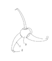
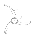
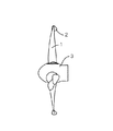
図1.は本発明のバックワードスキュードタービン翼(1)にT形先端翼(2)を装備した例の斜視図で、図2.は図1.の正面図、図3.は図1.の側面図である。
タービン翼(1)はバックワードスキューをつけた形状とし、その先端部円周に沿ってT形先端翼(2)を配置する。
The present invention will be described with reference to the drawings.
FIG. 1 is a perspective view of an example in which a backward-squeezed turbine blade (1) of the present invention is equipped with a T-shaped tip blade (2). FIG. FIG. FIG. FIG.
The turbine blade (1) is shaped with backward skew, and the T-shaped tip blade (2) is disposed along the circumference of the tip portion.
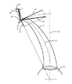
図4.は、本発明のバックワードスキュードタービン翼に装備されたT形先端翼(2)付近の流れと発生力のベクトル説明図である。T形先端翼(2)には軸方向の流速と回転方向速度が合成された回転速度(4)で接線方向から流入する。バックワードスキュードタービン翼(1)の回転によって半径方向から強い誘導速度(5)が流入する。流体は回転速度(4)と誘導速度(5)とで合成された流入速度(6)でT形先端翼(2)に流入することになり、T形先端翼(2)には、揚力(7)が発生し、同時に抗力(8)が発生する。これらを合成した揚抗合成力(9)から回転方向分力としてトルク(10)が得られる。 FIG. 4 is a vector explanatory diagram of the flow and generated force in the vicinity of the T-shaped tip blade (2) equipped in the backward skewed turbine blade of the present invention. The T-shaped tip wing (2) flows from the tangential direction at a rotational speed (4) obtained by combining the axial flow velocity and the rotational velocity. A strong induced velocity (5) flows in from the radial direction by the rotation of the backward skewed turbine blade (1). The fluid flows into the T-shaped tip wing (2) at the inflow velocity (6) synthesized by the rotational speed (4) and the induced velocity (5), and the T-shaped tip wing (2) has a lift ( 7) occurs, and drag (8) is generated at the same time. Torque (10) is obtained as a component in the rotational direction from the lift / drag combined force (9) obtained by combining these.
本発明のT形先端翼(2)の後縁側にフラップを装備することで、飛行機の翼制御のように、揺れ、捩じれ、トルク調整機能を持たせることができる。また、フラップをタービン翼(1)の圧力面側と背面側に分けて配置することでタービン翼(1)の揺れ、捩じれをより効果的に調整することができる。 By providing a flap on the trailing edge side of the T-shaped tip wing (2) of the present invention, it is possible to provide a function of adjusting the vibration, twisting, and torque as in airplane wing control. Moreover, the vibration and twist of the turbine blade (1) can be more effectively adjusted by arranging the flaps separately on the pressure surface side and the back surface side of the turbine blade (1).
以上の実施形態は、あくまでも要部の一例を示すものであり、本発明はかかる実施形態に限定されるものではなく、本発明の範囲を逸脱することなく変更および修正が可能である。 The above embodiment is merely an example of a main part, and the present invention is not limited to such an embodiment, and can be changed and modified without departing from the scope of the present invention.
海流発電、風力発電、水力発電など流体の種類を問わないT形先端翼付きバックワードスキュードタービン翼として、幅広い分野で利用することができる。 It can be used in a wide range of fields as a backward skewed turbine blade with a T-shaped tip blade regardless of the type of fluid, such as ocean current power generation, wind power generation, and hydroelectric power generation.
1 タービン翼
2 T形先端翼
3 ハブ
4 回転速度
5 誘導速度
6 流入速度
7 揚力
8 抗力
9 揚抗合成力
10 トルク
11 スキューライン
12 翼母線
1 Turbine blade 2 T-
Claims (1)
Priority Applications (1)
| Application Number | Priority Date | Filing Date | Title |
|---|---|---|---|
| JP2016049106A JP2017166324A (en) | 2016-03-14 | 2016-03-14 | T-type leading end blade for turbine |
Applications Claiming Priority (1)
| Application Number | Priority Date | Filing Date | Title |
|---|---|---|---|
| JP2016049106A JP2017166324A (en) | 2016-03-14 | 2016-03-14 | T-type leading end blade for turbine |
Publications (1)
| Publication Number | Publication Date |
|---|---|
| JP2017166324A true JP2017166324A (en) | 2017-09-21 |
Family
ID=59913147
Family Applications (1)
| Application Number | Title | Priority Date | Filing Date |
|---|---|---|---|
| JP2016049106A Pending JP2017166324A (en) | 2016-03-14 | 2016-03-14 | T-type leading end blade for turbine |
Country Status (1)
| Country | Link |
|---|---|
| JP (1) | JP2017166324A (en) |
Cited By (3)
| Publication number | Priority date | Publication date | Assignee | Title |
|---|---|---|---|---|
| JP2019210920A (en) * | 2018-06-08 | 2019-12-12 | 株式会社グローバルエナジー | Horizontal shaft rotor |
| CN111664052A (en) * | 2020-06-24 | 2020-09-15 | 曹正武 | Blade tip winglet propeller (fan) |
| JP2022158191A (en) * | 2021-04-01 | 2022-10-17 | 株式会社グローバルエナジー | Horizontal shaft windmill, horizontal shaft rotor and rotor blade |
-
2016
- 2016-03-14 JP JP2016049106A patent/JP2017166324A/en active Pending
Cited By (5)
| Publication number | Priority date | Publication date | Assignee | Title |
|---|---|---|---|---|
| JP2019210920A (en) * | 2018-06-08 | 2019-12-12 | 株式会社グローバルエナジー | Horizontal shaft rotor |
| KR20210016039A (en) * | 2018-06-08 | 2021-02-10 | 가부시키가이샤 글로벌 에너지 | Transverse rotor |
| KR102452988B1 (en) | 2018-06-08 | 2022-10-11 | 가부시키가이샤 글로벌 에너지 | transverse rotor |
| CN111664052A (en) * | 2020-06-24 | 2020-09-15 | 曹正武 | Blade tip winglet propeller (fan) |
| JP2022158191A (en) * | 2021-04-01 | 2022-10-17 | 株式会社グローバルエナジー | Horizontal shaft windmill, horizontal shaft rotor and rotor blade |
Similar Documents
| Publication | Publication Date | Title |
|---|---|---|
| US8777580B2 (en) | Secondary airfoil mounted on stall fence on wind turbine blade | |
| CN201461226U (en) | a leaf | |
| US9989033B2 (en) | Horizontal axis wind or water turbine with forked or multi-blade upper segments | |
| JP6154050B1 (en) | Wind turbine blade, wind turbine rotor, wind power generator, and vortex generator mounting method | |
| EP3037656B1 (en) | Rotor blade with vortex generators | |
| CN106536921B (en) | Turbine rotor for extracting wind energy and fluid power | |
| US10690112B2 (en) | Fluid turbine rotor blade with winglet design | |
| US10100808B2 (en) | Rotor blade extension body and wind turbine | |
| CN104736844A (en) | Wind turbine | |
| JP2017166324A (en) | T-type leading end blade for turbine | |
| JP6158019B2 (en) | Axial turbine generator | |
| EP3098436B1 (en) | Noise reducing flap with opening | |
| KR20130069812A (en) | Wind turbine blade, wind power generating device comprising same, and wind turbine blade design method | |
| WO2018046067A1 (en) | Wind turbine blade comprising an airfoil profile | |
| JP2009299650A (en) | Straightening fluid wheel | |
| JP5805913B1 (en) | Wind turbine blade and wind power generator equipped with the same | |
| KR20130008181A (en) | Wind power genelator | |
| JP2011089456A (en) | Vertical axis wind turbine with three-dimensional wing | |
| US12305611B2 (en) | Rotor blade of a wind turbine and corresponding wind turbine | |
| CN110173391A (en) | A kind of Large marine Axis Wind Turbine With A Tip Vane fusion winglet and wind energy conversion system | |
| CN103573530A (en) | Ocean current energy power generation type impeller of water turbine with flow guide cover | |
| Wang et al. | A numerical study on the performance improvement for a vertical-axis wind turbine at low tip-speed-ratios | |
| JP2017137809A (en) | Blade tip device for double blades | |
| KR101331133B1 (en) | Blade for aerogenerator | |
| JP2017015067A (en) | Wind turbine and water turbine utilizing flow |


