JP2017166317A - Vehicle door checker - Google Patents
Vehicle door checker Download PDFInfo
- Publication number
- JP2017166317A JP2017166317A JP2017078647A JP2017078647A JP2017166317A JP 2017166317 A JP2017166317 A JP 2017166317A JP 2017078647 A JP2017078647 A JP 2017078647A JP 2017078647 A JP2017078647 A JP 2017078647A JP 2017166317 A JP2017166317 A JP 2017166317A
- Authority
- JP
- Japan
- Prior art keywords
- door checker
- vehicle door
- stopper
- arm
- tip
- Prior art date
- Legal status (The legal status is an assumption and is not a legal conclusion. Google has not performed a legal analysis and makes no representation as to the accuracy of the status listed.)
- Granted
Links
- 229920005989 resin Polymers 0.000 claims abstract description 30
- 239000011347 resin Substances 0.000 claims abstract description 30
- 239000002184 metal Substances 0.000 claims abstract description 14
- NJPPVKZQTLUDBO-UHFFFAOYSA-N novaluron Chemical compound C1=C(Cl)C(OC(F)(F)C(OC(F)(F)F)F)=CC=C1NC(=O)NC(=O)C1=C(F)C=CC=C1F NJPPVKZQTLUDBO-UHFFFAOYSA-N 0.000 claims description 14
- 238000004519 manufacturing process Methods 0.000 description 9
- 238000005336 cracking Methods 0.000 description 4
- 230000004048 modification Effects 0.000 description 2
- 238000012986 modification Methods 0.000 description 2
- 229910000831 Steel Inorganic materials 0.000 description 1
- 239000013013 elastic material Substances 0.000 description 1
- 239000007769 metal material Substances 0.000 description 1
- 238000009751 slip forming Methods 0.000 description 1
- 229910001220 stainless steel Inorganic materials 0.000 description 1
- 239000010935 stainless steel Substances 0.000 description 1
- 239000010959 steel Substances 0.000 description 1
- 229920003002 synthetic resin Polymers 0.000 description 1
- 239000000057 synthetic resin Substances 0.000 description 1
Images
Landscapes
- Body Structure For Vehicles (AREA)
Abstract
【課題】ストッパ部における割れやひびの発生を抑制する。【解決手段】芯金26を樹脂28で包んでドアチェッカ20のアーム24を形成し、アーム24のストッパ部24bを、芯金26の先端面、先端面から連続する2つの面取り端面(2つの面取り端面のうちの一つが面取り端面26c)とが露出するよう形成する。これにより、ストッパ部24bを形成する樹脂28における残留応力を低減することができ、ストッパ部24bにおける割れやひびの発生を抑制することができる。【選択図】図5[PROBLEMS] To suppress the occurrence of cracks and cracks in a stopper portion. An arm 24 of a door checker 20 is formed by wrapping a core metal 26 with a resin 28, and a stopper portion 24b of the arm 24 is provided with two chamfered end faces (two One of the chamfered end faces is formed so that the chamfered end face 26c) is exposed. Thereby, the residual stress in the resin 28 forming the stopper portion 24b can be reduced, and the occurrence of cracks and cracks in the stopper portion 24b can be suppressed. [Selection] Figure 5
Description
本発明は、車両用ドアチェッカに関し、詳しくは、車体とドアとに取り付けられる車両用ドアチェッカに関する。 The present invention relates to a vehicle door checker, and more particularly to a vehicle door checker attached to a vehicle body and a door.
従来、この種の車両用ドアチェッカとしては、一端が自動車のボディに回動可能に取り付けられ先端に全開ストッパが設けられたチェックレバーと、チェックレバーが貫通されると共にドアに固着されるケースと、ケースに収納されチェックレバーの表面に摺接するシューとを備えるものが提案されている(例えば、特許文献1参照)。この車両用ドアチェッカでは、チェックレバーを、鋼板製の芯板と芯板を被覆する合成樹脂製の外皮とにより構成し、全開ストッパを、芯板の先端部に形成したピン穴に嵌合するアンカピンとチェックレバーの外皮に一体成形されアンカピンを被覆する合成樹脂製の膨大部とにより構成し、チェックレバーと全開ストッパとを一体成形している。これにより、全開ストッパをチェックレバーに取り付ける工程を行なう必要がないから、組立工程数の削減を図ることができる。 Conventionally, this type of vehicle door checker includes a check lever having one end rotatably attached to the body of an automobile and a fully open stopper provided at the tip, and a case through which the check lever penetrates and is fixed to the door. There has been proposed one including a shoe housed in a case and in sliding contact with the surface of the check lever (see, for example, Patent Document 1). In this vehicle door checker, the check lever is composed of a steel plate core plate and a synthetic resin outer cover that covers the core plate, and the fully open stopper is fitted into a pin hole formed at the tip of the core plate. The anchor pin and the check lever are integrally formed on the outer skin of the checker pin, and the checker pin and the fully open stopper are integrally formed. As a result, it is not necessary to perform a step of attaching the fully open stopper to the check lever, so that the number of assembly steps can be reduced.
上述の車両用ドアチェッカでは、全開ストッパの樹脂の内部に残留応力が生じ、製造時に割れやひびが生じる場合がある。製造時に割れやひびが生じない場合でも、残留応力により耐久期間を経過する前に割れやひびが生じて、所望の耐久性を発揮できない場合もある。こうした割れやひびは、製造歩留まりや製品の耐久性の低下を招くため、抑制されるのが望ましい。 In the above-described vehicle door checker, residual stress may be generated inside the resin of the fully-open stopper, and cracks and cracks may occur during manufacturing. Even when cracks and cracks do not occur at the time of manufacture, cracks and cracks may occur before the durability period elapses due to residual stress, and the desired durability may not be exhibited. Such cracks and cracks are preferably suppressed because they cause a reduction in manufacturing yield and product durability.
本発明の車両用ドアチェッカは、ストッパ部における割れやひびの発生を抑制することを主目的とする。 The main purpose of the vehicle door checker of the present invention is to suppress the occurrence of cracks and cracks in the stopper portion.
本発明の車両用ドアチェッカは、上述の主目的を達成するために以下の手段を採った。 The vehicle door checker of the present invention employs the following means in order to achieve the above-mentioned main object.
本発明の車両用ドアチェッカは、
車体とドアとに取り付けられる車両用ドアチェッカであって、
板状の芯金を樹脂で包むように形成され、前記車体に回動可能に取り付けられる取付部と、ドアの開角度を制限するストッパ部と、前記取付部と前記ストッパ部とを連結するアーム部と、を有するアームと、
前記ストッパ部が通過不能な貫通孔を有し、該貫通孔に前記アーム部を挿通した状態でドアに取り付けられるケースと、
前記アーム部に摺動可能に前記ケースに収納される摺動部材と、
を備え、
前記ストッパ部は、前記芯金の先端面が露出するように形成されている、
ことを要旨とする。
The vehicle door checker of the present invention is
A vehicle door checker attached to a vehicle body and a door,
A plate-shaped metal core is formed so as to be wrapped with resin, and is attached to the vehicle body so as to be able to rotate, a stopper unit that limits the opening angle of the door, and an arm unit that connects the mounting unit and the stopper unit. And an arm having
A case in which the stopper portion has a through-hole through which the passage is impossible and is attached to the door in a state where the arm portion is inserted through the through-hole;
A sliding member housed in the case so as to be slidable on the arm portion;
With
The stopper portion is formed so that the tip surface of the core bar is exposed.
This is the gist.
この本発明の車両用ドアチェッカでは、板状の芯金を樹脂で包むように形成されて車体に回動可能に取り付けられる取付部とドアの開角度を制限するストッパ部と取付部とストッパ部とを連結するアーム部とを有するアームと、ストッパ部が通過不能な貫通孔にアーム部を挿通した状態でドアに取り付けられるケースと、アーム部に摺動可能にケースに収納された摺動部材と、により構成されている。そして、アームのストッパ部は、芯金の先端面が露出するように形成されている。ストッパ部を形成する樹脂には、製造する過程で残留応力が生じる場合があるが、芯金の先端面が露出しているため、露出部縁部の樹脂には残留応力は発生せず、その近傍の樹脂には残留応力が発生してもその値は小さい。このため、製造時および使用時におけるストッパ部における割れやひびの発生を抑制することができる。 In the vehicle door checker of the present invention, a plate-shaped cored bar is formed so as to be wrapped with resin, and is attached to the vehicle body so as to be rotatable, a stopper portion for limiting an opening angle of the door, a mounting portion, and a stopper portion. An arm having an arm for connecting the arm, a case attached to the door in a state where the arm is inserted through a through-hole through which the stopper cannot pass, and a sliding member housed in the case slidably in the arm , Is configured. And the stopper part of an arm is formed so that the front end surface of a metal core may be exposed. Resin that forms the stopper part may cause residual stress during the manufacturing process, but since the tip of the core is exposed, no residual stress is generated in the resin at the edge of the exposed part. Even if residual stress occurs in the nearby resin, the value is small. For this reason, generation | occurrence | production of the crack in the stopper part at the time of manufacture and use can be suppressed.
こうした本発明の車両用ドアチェッカにおいて、前記芯金は、前記ストッパ部において前記アーム部より幅広となる幅広部が先端から連続して形成されており、前記ストッパ部は、前記幅広部の端面のうちの前記先端面から連続する一部の端面が前記先端面から連続して露出するよう形成されている、ものとすることもできる。こうすれば、芯金の露出部分が大きくなり、残留応力を発生しない樹脂部分や残留応力が発生してもその値が小さい樹脂部分を多くすることができる。この結果、製造時および使用時におけるストッパ部における割れやひびの発生をより抑制することができる。この態様の本発明の車両用ドアチェッカにおいて、前記先端面は、前記芯金の長さ方向に対して略垂直面となるよう形成されており、前記先端面から連続する端面は、前記先端面に対して面取りするように前記先端面の方向と前記芯金の長さ方向とに対して30度から60度の角度をもつ平面により形成されている、ものとすることもできる。 In such a vehicle door checker according to the present invention, the core metal is formed such that a wide portion that is wider than the arm portion in the stopper portion is continuously formed from the tip, and the stopper portion is formed on an end surface of the wide portion. Of these, a part of the end surface continuous from the tip surface may be formed so as to be continuously exposed from the tip surface. By doing this, the exposed portion of the core metal becomes large, and it is possible to increase the resin portion that does not generate residual stress and the resin portion that has a small value even when residual stress occurs. As a result, it is possible to further suppress the occurrence of cracks and cracks in the stopper portion during manufacture and use. In this aspect of the vehicle door checker of the present invention, the front end surface is formed to be a substantially vertical surface with respect to the length direction of the core metal, and the end surface continuous from the front end surface is the front end surface. It is also possible to be formed by a plane having an angle of 30 to 60 degrees with respect to the direction of the tip surface and the length direction of the core bar so as to be chamfered.
また、本発明の車両用ドアチェッカにおいて、前記ストッパ部は、前記芯金の先端面を有する先端部と、前記先端部から連続して樹脂が前記アーム部より肉厚になるように形成され前記ケースが当接する台座部と、を有する、ものとすることもできる。このようにケースが当接する台座部をアーム部より肉厚になるよう形成することにより、ストッパ部の強度をより高くすることができる。この場合、前記先端部は、略四角錐台形状となるよう形成されており、前記台座部は、略四角柱形状となるよう形成されている、ものとすることもできる。 Further, in the vehicle door checker according to the present invention, the stopper portion is formed so that a resin has a thickness thicker than that of the arm portion, and a tip portion having a tip surface of the cored bar and the tip portion. And a pedestal portion with which the case abuts. By forming the pedestal part with which the case comes into contact so as to be thicker than the arm part, the strength of the stopper part can be further increased. In this case, the tip portion may be formed in a substantially quadrangular pyramid shape, and the pedestal portion may be formed in a substantially quadrangular prism shape.
次に、本発明を実施するための形態を実施例を用いて説明する。 Next, the form for implementing this invention is demonstrated using an Example.
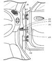
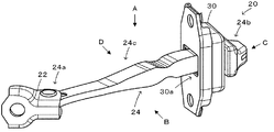
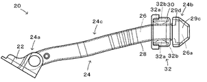
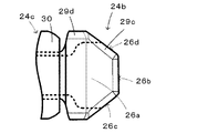
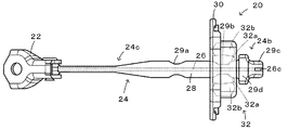
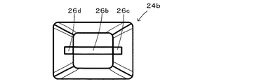
図1は、本発明の一実施例としてのドアチェッカ20が車体とドアとに取り付けられている様子を示す説明図であり、図2は、ドアチェッカ20の構成の概略を示す説明図であり、図3は、ドアチェッカ20を図2におけるA方向から視た外観の概略を示す上面図であり、図4は、図3のストッパ部24bを拡大した部分拡大図であり、図5は、ドアチェッカ20を図2におけるB方向から視た外観の概略を示す側面図であり、図6は、ストッパ部24bを図2におけるC方向から視た外観の概略を示す説明図である。
FIG. 1 is an explanatory view showing a state in which a
ドアチェッカ20は、車体とドアとに取り付けられる装置であり、図1に示すように、車体の取付部Bの中央とドアの取付部Dの中央とに取り付けられている。なお、ドアは、ドアチェッカ20の上方および下方で車体の取付部Bとドアの取付部Dに取り付けられた2つのドアヒンジH1,H2により、開閉可能に支持されている。
The
ドアチェッカ20は、図1〜図3,図5に示すように、ステンレスなどの金属材料により形成された板状の芯金26をプラスチックなどの樹脂28で包んで形成されたアーム24と、ドアDに取り付けられたケース30と、ケース30に収納された摺動部材32と、により構成されている。
As shown in FIGS. 1 to 3 and 5, the
アーム24は、図2,図3,図5に示すように、図中左端から右端まで延在するように芯金26を樹脂28で包んで形成されており、ブラケット22により車体Bに回動可能に取り付けられた取付部24aと、ドアの開角度を制限するストッパ部24bと、取付部24aとストッパ部24bとを連結するアーム部24cと、を有する。
2, 3, and 5, the
アーム部24cは、全体として樹脂28が取付部24aからストッパ部24bに向かって徐々に肉厚になるように形成されており、中央より若干ストッパ部24b側の位置にドアを中間開度で保持するための凹部29aと、ストッパ部24bの近傍の位置にドアを全開角度で保持するための凹部29bとが形成されている。
The
ストッパ部24bは、図2〜図6に示すように、芯金26の先端面26bと後述する面取り端面26c,26dとが露出するように略四角錐台形状に形成された先端部29cと、この先端部29cに連続するように且つアーム部24cより肉厚になるように略四角柱形状に形成された台座部29dと、により構成されている。このように、台座部29dの樹脂をアーム部24cより肉厚となるよう形成することにより、台座部29dの強度を高めることができる。
As shown in FIGS. 2 to 6, the
ストッパ部24bの芯金26は、図3,図4に示すように、台座部29dの中央から先端に向かってアーム部24cより幅広となるよう幅広部26aとして形成されており、その先端面26b側の端部は幅広の矩形端部の角が面取りされた形状となるように形成されている。即ち、芯金26の先端面26bは芯金26の長さ方向に対して直交する垂直面として形成されており、この先端面に連続する両側の面取り端面26c,26dは芯金26の長さ方向に対して略45度の角度をもった垂直面として形成されている。そして、この面取り端面26c,26dは共に先端面26bと同様に露出するように樹脂28が形成されている。このように、芯金26の先端面26bやこれに連続する面取り端面26c,26dを露出するのは、その近傍の樹脂に残留応力を生じさせないようにしたり残留応力が生じてもその値を小さなものとするためである。樹脂の内部に発生する残留応力は、樹脂が硬化する際の部位による温度差や樹脂と芯金との熱膨張率の差などに基づいて生じるが、芯金26の先端面26bや面取り端面26c,26dの縁部では樹脂は開放端となるために残留応力は生じない。また、その近傍では、残留応力が生じてもその値は小さくなる。このため、残留応力によって生じる樹脂の割れやひびを抑制することができる。
As shown in FIGS. 3 and 4, the
ケース30は、図2に示すように、アーム24のストッパ部24bの最大径より小さい径の貫通孔30aを備え、貫通孔30aにアーム24のアーム部24cを挿通した状態でドアDに取り付けられている。
As shown in FIG. 2, the
摺動部材32は、図3,図5に示すように、プラスチックなどにより形成されてアーム部24cを挟むように配置された2つのスライダ32aと、ゴムなどの弾性材料により形成されて2つのスライダ32aを図3,5における上下方向外側から押圧するダンパ32bとを備えている。スライダ32aは、ダンパ32bに押圧されることによりアーム部24cの表面を図3,図5における左右方向に摺動する。こうしたダンパ32bによるスライダ32aの押圧により、スライダ32aがアーム部24cの凹部29aに位置するとき(例えば、30度の中間開度のとき)にドアを中間開度で保持し、スライダ32aがアーム部24cの凹部29bに位置するとき(例えば、60度の全開角度のとき)にドアを全開角度で保持することができる。なお、スライダ32aがアーム部24cの凹部29bより図3,図5における右に摺動すると、ケース30がストッパ部24bに当接して、ドアの開角度が全開角度を大きく超えないよう制限される。
As shown in FIGS. 3 and 5, the sliding
以上説明した実施例のドアチェッカ20では、ストッパ部24bにおいて、芯金26の先端面26bや面取り端面26c,26dを露出するよう形成することにより、樹脂内部の残留応力を小さくすることができる。この結果、製造時や使用時に残留応力によって生じる樹脂の割れやひびを抑制することができる。
In the
また、ストッパ部24bの台座部29dの樹脂がアーム部24cより肉厚になるように形成したから、台座部29dの強度をより高めることができる。
Further, since the resin of the
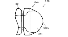
実施例のドアチェッカ20では、ストッパ部24bにおいて、芯金26の先端面26bを芯金26の長さ方向に対して直交する垂直面として形成し、この先端面26bに連続する両側の面取り端面26c,26dを芯金26の長さ方向に対して略45度の角度をもった垂直面として形成したが、面取り端面26c,26dの芯金26の長さ方向に対する角度は45度に限定されるものではなく、30度から60度の範囲の角度をもった垂直面として形成するものとしてもよい。また、図7の変形例のストッパ部124bに例示するように、先端面126bを曲面に形成し、この曲面の一部または全部が露出するようストッパ部124bを形成するものとしてもよい。
In the
実施例のドアチェッカ20では、ストッパ部24bを、芯金26の先端面26b,面取り端面26c,26dが露出するよう形成するものとしたが、先端面26bと面取り端面26c,26dの一部とが露出するものとしてもよいし、面取り端面26c,26dは露出せずに先端面26bのみが露出するものとしてもよい。
In the
実施例のドアチェッカ20では、ストッパ部24bの先端部29cを略四角錐台形状となるよう形成し、台座部29dを略四角柱形状となるよう形成するものとしたが、先端部29c,台座部29dの形状は適宜変更することができ、例えば、先端部29cを略四角柱形状となるよう形成し、台座部29dを先端部29cから連続する四角錘台形状となるよう形成してもよい。また、ストッパ部24bを先端部29cおよび台座部29dから形成するものに限定されるものではなく、例えば、ストッパ部24bの全体を四角錐台形状や四角柱形状に形成するものとしてもよい。
In the
実施例の主要な要素と課題を解決するための手段の欄に記載した発明の主要な要素との対応関係について説明する。実施例では、芯金26が「芯金」に相当し、樹脂28が「樹脂」に相当し、取付部24aが「取り付け部」に相当し、ストッパ部24bが「ストッパ部」に相当し、アーム部24cが「アーム部」に相当し、アーム24が「アーム」に相当し、ケース30が「ケース」に相当し、摺動部材32が「摺動部材」に相当する。
The correspondence between the main elements of the embodiment and the main elements of the invention described in the column of means for solving the problems will be described. In the embodiment, the
なお、実施例の主要な要素と課題を解決するための手段の欄に記載した発明の主要な要素との対応関係は、実施例が課題を解決するための手段の欄に記載した発明を実施するための形態を具体的に説明するための一例であることから、課題を解決するための手段の欄に記載した発明の要素を限定するものではない。即ち、課題を解決するための手段の欄に記載した発明についての解釈はその欄の記載に基づいて行なわれるべきものであり、実施例は課題を解決するための手段の欄に記載した発明の具体的な一例に過ぎないものである。 The correspondence between the main elements of the embodiment and the main elements of the invention described in the column of means for solving the problem is the same as that of the embodiment described in the column of means for solving the problem. Therefore, the elements of the invention described in the column of means for solving the problems are not limited. That is, the interpretation of the invention described in the column of means for solving the problems should be made based on the description of the column, and the examples are those of the invention described in the column of means for solving the problems. It is only a specific example.
以上、本発明を実施するための形態について実施例を用いて説明したが、本発明はこうした実施例に何等限定されるものではなく、本発明の要旨を逸脱しない範囲内において、種々なる形態で実施し得ることは勿論である。 As mentioned above, although the form for implementing this invention was demonstrated using the Example, this invention is not limited at all to such an Example, In the range which does not deviate from the summary of this invention, it is with various forms. Of course, it can be implemented.
本発明は、車両用ドアチェッカの製造産業などに利用可能である。 The present invention is applicable to the vehicle door checker manufacturing industry and the like.
20,120 ドアチェッカ、22 ブラケット、24 アーム、24a,B,D 取付部、24b,124b ストッパ部、24c アーム部,26 芯金、26a 幅広部、26b 先端面、26c,26d 面取り端面、28 樹脂、29a,29b 凹部、29c 先端部、29d 台座部、30 ケース、30a 貫通孔、32 摺動部材、32a スライダ、32b ダンパ、126b 先端面、H1,H2 ドアヒンジ。
20, 120 Door checker, 22 Bracket, 24 arm, 24a, B, D Mounting part, 24b, 124b Stopper part, 24c Arm part, 26 Core metal, 26a Wide part, 26b End face, 26c, 26d Chamfered end face, 28
Claims (6)
板状の芯金を樹脂で包むように形成され、前記車体に回動可能に取り付けられる取付部と、ドアの開角度を制限するストッパ部と、前記取付部と前記ストッパ部とを連結するアーム部と、を有するアームと、
前記ストッパ部が通過不能な貫通孔を有し、該貫通孔に前記アーム部を挿通した状態でドアに取り付けられるケースと、
前記アーム部に摺動可能に前記ケースに収納される摺動部材と、
を備え、
前記ストッパ部は、前記芯金の先端面が露出するように形成されている、
ことを特徴とする車両用ドアチェッカ。 A vehicle door checker attached to a vehicle body and a door,
A plate-shaped metal core is formed so as to be wrapped with resin, and is attached to the vehicle body so as to be able to rotate, a stopper unit that limits the opening angle of the door, and an arm unit that connects the mounting unit and the stopper unit. And an arm having
A case in which the stopper portion has a through-hole through which the passage is impossible and is attached to the door in a state where the arm portion is inserted through the through-hole;
A sliding member housed in the case so as to be slidable on the arm portion;
With
The stopper portion is formed so that the tip surface of the core bar is exposed.
A vehicle door checker characterized by the above.
前記芯金は、前記ストッパ部において前記アーム部より幅広となる幅広部が先端から連続して形成されており、
前記ストッパ部は、前記幅広部の端面のうちの前記先端面から連続する一部の端面が前記先端面から連続して露出するよう形成されている、
車両用ドアチェッカ。 The vehicle door checker according to claim 1,
The cored bar is formed continuously from the tip with a wide part that is wider than the arm part in the stopper part,
The stopper portion is formed such that a part of the end surface continuous from the tip surface of the wide portion is exposed continuously from the tip surface.
Vehicle door checker.
前記先端面は、前記芯金の長さ方向に対して略垂直面となるよう形成されており、
前記先端面から連続する端面は、前記先端面に対して面取りするように前記先端面の方向と前記芯金の長さ方向とに対して30度から60度の角度をもつ平面により形成されている、
車両用ドアチェッカ。 The vehicle door checker according to claim 2,
The tip surface is formed to be a substantially vertical surface with respect to the length direction of the cored bar,
An end surface continuous from the tip surface is formed by a plane having an angle of 30 to 60 degrees with respect to the direction of the tip surface and the length direction of the core bar so as to be chamfered with respect to the tip surface. Yes,
Vehicle door checker.
前記ストッパ部は、前記芯金のアーム部における幅以上の幅に亘って前記芯金の端面が露出している、
車両用ドアチェッカ。 The vehicle door checker according to claim 2 or 3,
The stopper part has an end face of the core bar exposed over a width equal to or greater than the width of the arm part of the core bar.
Vehicle door checker.
前記ストッパ部は、前記芯金の先端面を有する先端部と、前記先端部から連続して樹脂が前記アーム部より肉厚になるように形成され前記ケースが当接する台座部と、を有する、
車両用ドアチェッカ。 The vehicle door checker according to any one of claims 1 to 4,
The stopper portion includes a distal end portion having a distal end surface of the cored bar, and a pedestal portion that is formed so that a resin is thicker than the arm portion continuously from the distal end portion, and the case contacts.
Vehicle door checker.
前記先端部は、略四角錐台形状となるよう形成されており、
前記台座部は、略四角柱形状となるよう形成されている、
車両用ドアチェッカ。 The vehicle door checker according to claim 5,
The tip is formed to have a substantially quadrangular frustum shape,
The pedestal portion is formed to have a substantially quadrangular prism shape,
Vehicle door checker.
Priority Applications (1)
| Application Number | Priority Date | Filing Date | Title |
|---|---|---|---|
| JP2017078647A JP6495367B2 (en) | 2017-04-12 | 2017-04-12 | Vehicle door checker |
Applications Claiming Priority (1)
| Application Number | Priority Date | Filing Date | Title |
|---|---|---|---|
| JP2017078647A JP6495367B2 (en) | 2017-04-12 | 2017-04-12 | Vehicle door checker |
Related Parent Applications (1)
| Application Number | Title | Priority Date | Filing Date |
|---|---|---|---|
| JP2014005191U Continuation JP3194829U (en) | 2014-09-30 | 2014-09-30 | Vehicle door checker |
Publications (2)
| Publication Number | Publication Date |
|---|---|
| JP2017166317A true JP2017166317A (en) | 2017-09-21 |
| JP6495367B2 JP6495367B2 (en) | 2019-04-03 |
Family
ID=59909901
Family Applications (1)
| Application Number | Title | Priority Date | Filing Date |
|---|---|---|---|
| JP2017078647A Active JP6495367B2 (en) | 2017-04-12 | 2017-04-12 | Vehicle door checker |
Country Status (1)
| Country | Link |
|---|---|
| JP (1) | JP6495367B2 (en) |
Cited By (1)
| Publication number | Priority date | Publication date | Assignee | Title |
|---|---|---|---|---|
| JP2024072074A (en) * | 2022-11-15 | 2024-05-27 | スズキ株式会社 | Door opening degree regulation mechanism for vehicle and method for manufacturing the lever |
Citations (3)
| Publication number | Priority date | Publication date | Assignee | Title |
|---|---|---|---|---|
| JP2001317259A (en) * | 2000-05-08 | 2001-11-16 | Fec Chain:Kk | Arm for door checking apparatus, and method for producing the same |
| US20060150366A1 (en) * | 2005-01-13 | 2006-07-13 | Katsuhiro Matsuki | Door checker for automobile |
| JP2013217077A (en) * | 2012-04-06 | 2013-10-24 | Mitsui Kinzoku Act Corp | Check link device |
-
2017
- 2017-04-12 JP JP2017078647A patent/JP6495367B2/en active Active
Patent Citations (3)
| Publication number | Priority date | Publication date | Assignee | Title |
|---|---|---|---|---|
| JP2001317259A (en) * | 2000-05-08 | 2001-11-16 | Fec Chain:Kk | Arm for door checking apparatus, and method for producing the same |
| US20060150366A1 (en) * | 2005-01-13 | 2006-07-13 | Katsuhiro Matsuki | Door checker for automobile |
| JP2013217077A (en) * | 2012-04-06 | 2013-10-24 | Mitsui Kinzoku Act Corp | Check link device |
Cited By (2)
| Publication number | Priority date | Publication date | Assignee | Title |
|---|---|---|---|---|
| JP2024072074A (en) * | 2022-11-15 | 2024-05-27 | スズキ株式会社 | Door opening degree regulation mechanism for vehicle and method for manufacturing the lever |
| JP7811331B2 (en) | 2022-11-15 | 2026-02-05 | スズキ株式会社 | Vehicle door opening regulation mechanism and method for manufacturing the lever |
Also Published As
| Publication number | Publication date |
|---|---|
| JP6495367B2 (en) | 2019-04-03 |
Similar Documents
| Publication | Publication Date | Title |
|---|---|---|
| JP5239101B2 (en) | Automotive door check link device | |
| JP3194829U (en) | Vehicle door checker | |
| KR101636135B1 (en) | armrest hinge for automobile | |
| JP2014034865A (en) | Check link device | |
| JP6495367B2 (en) | Vehicle door checker | |
| JP5382542B2 (en) | Check link device | |
| CN101603390B (en) | A support member for window partition board and partition board having the support member | |
| CN206380061U (en) | A kind of stretching structure of earphone and the headphone with the structure | |
| EP3173560A1 (en) | Covering member for concealed hinges | |
| CN107489324B (en) | Door limiter devices for vehicles | |
| JP4522977B2 (en) | Inside door handle device | |
| JP6175692B2 (en) | Automotive door check link device | |
| JP6951588B2 (en) | Hinge device | |
| JP6060838B2 (en) | Stopper jig for automobile | |
| CN216128112U (en) | Vehicle door opening limit device | |
| JP6481358B2 (en) | Vehicle interior trim | |
| KR102109386B1 (en) | Bracket and Insert For Fixing of Vehicle Room Mirror | |
| JP5007711B2 (en) | Automotive door checker | |
| CN209538969U (en) | Limit link device | |
| JP6226806B2 (en) | Hinge positioning structure | |
| JP6354250B2 (en) | Door opening adjustment device | |
| EP3990731B1 (en) | Hinge for furniture | |
| CN106458016A (en) | Hatch for closing off access to a motor vehicle power supply interface | |
| JP6736219B2 (en) | Locking device | |
| CN213742823U (en) | Door opening limit device for automobiles |
Legal Events
| Date | Code | Title | Description |
|---|---|---|---|
| A521 | Request for written amendment filed |
Free format text: JAPANESE INTERMEDIATE CODE: A523 Effective date: 20170721 |
|
| A977 | Report on retrieval |
Free format text: JAPANESE INTERMEDIATE CODE: A971007 Effective date: 20180115 |
|
| A131 | Notification of reasons for refusal |
Free format text: JAPANESE INTERMEDIATE CODE: A131 Effective date: 20180313 |
|
| A02 | Decision of refusal |
Free format text: JAPANESE INTERMEDIATE CODE: A02 Effective date: 20181113 |
|
| A521 | Request for written amendment filed |
Free format text: JAPANESE INTERMEDIATE CODE: A523 Effective date: 20181227 |
|
| A911 | Transfer to examiner for re-examination before appeal (zenchi) |
Free format text: JAPANESE INTERMEDIATE CODE: A911 Effective date: 20190109 |
|
| TRDD | Decision of grant or rejection written | ||
| A01 | Written decision to grant a patent or to grant a registration (utility model) |
Free format text: JAPANESE INTERMEDIATE CODE: A01 Effective date: 20190205 |
|
| A61 | First payment of annual fees (during grant procedure) |
Free format text: JAPANESE INTERMEDIATE CODE: A61 Effective date: 20190306 |
|
| R150 | Certificate of patent or registration of utility model |
Ref document number: 6495367 Country of ref document: JP Free format text: JAPANESE INTERMEDIATE CODE: R150 |
|
| R250 | Receipt of annual fees |
Free format text: JAPANESE INTERMEDIATE CODE: R250 |
|
| R250 | Receipt of annual fees |
Free format text: JAPANESE INTERMEDIATE CODE: R250 |
|
| R250 | Receipt of annual fees |
Free format text: JAPANESE INTERMEDIATE CODE: R250 |
|
| R250 | Receipt of annual fees |
Free format text: JAPANESE INTERMEDIATE CODE: R250 |