JP2017165146A - Communication system and communication device - Google Patents
Communication system and communication device Download PDFInfo
- Publication number
- JP2017165146A JP2017165146A JP2016049875A JP2016049875A JP2017165146A JP 2017165146 A JP2017165146 A JP 2017165146A JP 2016049875 A JP2016049875 A JP 2016049875A JP 2016049875 A JP2016049875 A JP 2016049875A JP 2017165146 A JP2017165146 A JP 2017165146A
- Authority
- JP
- Japan
- Prior art keywords
- signal
- unit
- vehicle
- control unit
- target
- Prior art date
- Legal status (The legal status is an assumption and is not a legal conclusion. Google has not performed a legal analysis and makes no representation as to the accuracy of the status listed.)
- Granted
Links
Images


Classifications
-
- B—PERFORMING OPERATIONS; TRANSPORTING
- B60—VEHICLES IN GENERAL
- B60C—VEHICLE TYRES; TYRE INFLATION; TYRE CHANGING; CONNECTING VALVES TO INFLATABLE ELASTIC BODIES IN GENERAL; DEVICES OR ARRANGEMENTS RELATED TO TYRES
- B60C23/00—Devices for measuring, signalling, controlling, or distributing tyre pressure or temperature, specially adapted for mounting on vehicles; Arrangement of tyre inflating devices on vehicles, e.g. of pumps or of tanks; Tyre cooling arrangements
- B60C23/02—Signalling devices actuated by tyre pressure
- B60C23/04—Signalling devices actuated by tyre pressure mounted on the wheel or tyre
- B60C23/0408—Signalling devices actuated by tyre pressure mounted on the wheel or tyre transmitting the signals by non-mechanical means from the wheel or tyre to a vehicle body mounted receiver
- B60C23/0422—Signalling devices actuated by tyre pressure mounted on the wheel or tyre transmitting the signals by non-mechanical means from the wheel or tyre to a vehicle body mounted receiver characterised by the type of signal transmission means
- B60C23/0433—Radio signals
- B60C23/0435—Vehicle body mounted circuits, e.g. transceiver or antenna fixed to central console, door, roof, mirror or fender
- B60C23/0438—Vehicle body mounted circuits, e.g. transceiver or antenna fixed to central console, door, roof, mirror or fender comprising signal transmission means, e.g. for a bidirectional communication with a corresponding wheel mounted receiver
- B60C23/044—Near field triggers, e.g. magnets or triggers with 125 KHz
-
- B—PERFORMING OPERATIONS; TRANSPORTING
- B60—VEHICLES IN GENERAL
- B60C—VEHICLE TYRES; TYRE INFLATION; TYRE CHANGING; CONNECTING VALVES TO INFLATABLE ELASTIC BODIES IN GENERAL; DEVICES OR ARRANGEMENTS RELATED TO TYRES
- B60C23/00—Devices for measuring, signalling, controlling, or distributing tyre pressure or temperature, specially adapted for mounting on vehicles; Arrangement of tyre inflating devices on vehicles, e.g. of pumps or of tanks; Tyre cooling arrangements
- B60C23/02—Signalling devices actuated by tyre pressure
- B60C23/04—Signalling devices actuated by tyre pressure mounted on the wheel or tyre
- B60C23/0408—Signalling devices actuated by tyre pressure mounted on the wheel or tyre transmitting the signals by non-mechanical means from the wheel or tyre to a vehicle body mounted receiver
- B60C23/0422—Signalling devices actuated by tyre pressure mounted on the wheel or tyre transmitting the signals by non-mechanical means from the wheel or tyre to a vehicle body mounted receiver characterised by the type of signal transmission means
- B60C23/0433—Radio signals
- B60C23/0435—Vehicle body mounted circuits, e.g. transceiver or antenna fixed to central console, door, roof, mirror or fender
- B60C23/0444—Antenna structures, control or arrangements thereof, e.g. for directional antennas, diversity antenna, antenna multiplexing or antennas integrated in fenders
-
- B—PERFORMING OPERATIONS; TRANSPORTING
- B60—VEHICLES IN GENERAL
- B60C—VEHICLE TYRES; TYRE INFLATION; TYRE CHANGING; CONNECTING VALVES TO INFLATABLE ELASTIC BODIES IN GENERAL; DEVICES OR ARRANGEMENTS RELATED TO TYRES
- B60C23/00—Devices for measuring, signalling, controlling, or distributing tyre pressure or temperature, specially adapted for mounting on vehicles; Arrangement of tyre inflating devices on vehicles, e.g. of pumps or of tanks; Tyre cooling arrangements
- B60C23/02—Signalling devices actuated by tyre pressure
- B60C23/04—Signalling devices actuated by tyre pressure mounted on the wheel or tyre
- B60C23/0408—Signalling devices actuated by tyre pressure mounted on the wheel or tyre transmitting the signals by non-mechanical means from the wheel or tyre to a vehicle body mounted receiver
- B60C23/0422—Signalling devices actuated by tyre pressure mounted on the wheel or tyre transmitting the signals by non-mechanical means from the wheel or tyre to a vehicle body mounted receiver characterised by the type of signal transmission means
- B60C23/0433—Radio signals
- B60C23/0447—Wheel or tyre mounted circuits
- B60C23/0455—Transmission control of wireless signals
- B60C23/0461—Transmission control of wireless signals externally triggered, e.g. by wireless request signal, magnet or manual switch
-
- B—PERFORMING OPERATIONS; TRANSPORTING
- B60—VEHICLES IN GENERAL
- B60C—VEHICLE TYRES; TYRE INFLATION; TYRE CHANGING; CONNECTING VALVES TO INFLATABLE ELASTIC BODIES IN GENERAL; DEVICES OR ARRANGEMENTS RELATED TO TYRES
- B60C23/00—Devices for measuring, signalling, controlling, or distributing tyre pressure or temperature, specially adapted for mounting on vehicles; Arrangement of tyre inflating devices on vehicles, e.g. of pumps or of tanks; Tyre cooling arrangements
- B60C23/02—Signalling devices actuated by tyre pressure
- B60C23/04—Signalling devices actuated by tyre pressure mounted on the wheel or tyre
- B60C23/0408—Signalling devices actuated by tyre pressure mounted on the wheel or tyre transmitting the signals by non-mechanical means from the wheel or tyre to a vehicle body mounted receiver
- B60C23/0422—Signalling devices actuated by tyre pressure mounted on the wheel or tyre transmitting the signals by non-mechanical means from the wheel or tyre to a vehicle body mounted receiver characterised by the type of signal transmission means
- B60C23/0433—Radio signals
- B60C23/0447—Wheel or tyre mounted circuits
- B60C23/0455—Transmission control of wireless signals
- B60C23/0462—Structure of transmission protocol
-
- H—ELECTRICITY
- H04—ELECTRIC COMMUNICATION TECHNIQUE
- H04B—TRANSMISSION
- H04B1/00—Details of transmission systems, not covered by a single one of groups H04B3/00 - H04B13/00; Details of transmission systems not characterised by the medium used for transmission
- H04B1/38—Transceivers, i.e. devices in which transmitter and receiver form a structural unit and in which at least one part is used for functions of transmitting and receiving
- H04B1/3822—Transceivers, i.e. devices in which transmitter and receiver form a structural unit and in which at least one part is used for functions of transmitting and receiving specially adapted for use in vehicles
-
- H—ELECTRICITY
- H04—ELECTRIC COMMUNICATION TECHNIQUE
- H04W—WIRELESS COMMUNICATION NETWORKS
- H04W4/00—Services specially adapted for wireless communication networks; Facilities therefor
- H04W4/30—Services specially adapted for particular environments, situations or purposes
- H04W4/38—Services specially adapted for particular environments, situations or purposes for collecting sensor information
-
- H—ELECTRICITY
- H04—ELECTRIC COMMUNICATION TECHNIQUE
- H04W—WIRELESS COMMUNICATION NETWORKS
- H04W4/00—Services specially adapted for wireless communication networks; Facilities therefor
- H04W4/30—Services specially adapted for particular environments, situations or purposes
- H04W4/40—Services specially adapted for particular environments, situations or purposes for vehicles, e.g. vehicle-to-pedestrians [V2P]
- H04W4/48—Services specially adapted for particular environments, situations or purposes for vehicles, e.g. vehicle-to-pedestrians [V2P] for in-vehicle communication
-
- H—ELECTRICITY
- H04—ELECTRIC COMMUNICATION TECHNIQUE
- H04W—WIRELESS COMMUNICATION NETWORKS
- H04W4/00—Services specially adapted for wireless communication networks; Facilities therefor
- H04W4/80—Services using short range communication, e.g. near-field communication [NFC], radio-frequency identification [RFID] or low energy communication
-
- Y—GENERAL TAGGING OF NEW TECHNOLOGICAL DEVELOPMENTS; GENERAL TAGGING OF CROSS-SECTIONAL TECHNOLOGIES SPANNING OVER SEVERAL SECTIONS OF THE IPC; TECHNICAL SUBJECTS COVERED BY FORMER USPC CROSS-REFERENCE ART COLLECTIONS [XRACs] AND DIGESTS
- Y02—TECHNOLOGIES OR APPLICATIONS FOR MITIGATION OR ADAPTATION AGAINST CLIMATE CHANGE
- Y02D—CLIMATE CHANGE MITIGATION TECHNOLOGIES IN INFORMATION AND COMMUNICATION TECHNOLOGIES [ICT], I.E. INFORMATION AND COMMUNICATION TECHNOLOGIES AIMING AT THE REDUCTION OF THEIR OWN ENERGY USE
- Y02D30/00—Reducing energy consumption in communication networks
- Y02D30/70—Reducing energy consumption in communication networks in wireless communication networks
Abstract
Description
本発明は、複数の機器に信号が送信される通信システム、及び、該通信システムが備える通信装置に関する。 The present invention relates to a communication system in which signals are transmitted to a plurality of devices, and a communication apparatus provided in the communication system.
車両では、複数の電気機器がECU(Electronic Control Unit)にワイヤーハーネスによって接続されている。ECUは、複数の電気機器夫々に制御信号を、ワイヤーハーネスを介して送信し、これらの動作を制御する。 In a vehicle, a plurality of electric devices are connected to an ECU (Electronic Control Unit) by a wire harness. The ECU transmits a control signal to each of the plurality of electric devices via the wire harness to control these operations.
特許文献1では、車両に搭載された足元ランプ、ルームランプ及びカーテシランプが有線でECUに接続されている。ECUは、これらに制御信号を各別に送信することによって、前述したランプ夫々に点灯、点滅又は消灯を行わせる。
In
当然のことながら、車両が重い程、車両が同一の速度で同一距離を走行するために必要なガソリン又は電力の量は大きく、燃費が悪い。また、車両に搭載される装置が消費する電力は小さいことが好ましい。このため、ECUが複数の車載機器に信号を送信する車両用の通信システムとして、低消費電力であり、かつ、軽い通信システムが要求されている。 Of course, the heavier the vehicle, the greater the amount of gasoline or power required for the vehicle to travel the same distance at the same speed, resulting in poor fuel economy. Moreover, it is preferable that the power consumed by the device mounted on the vehicle is small. For this reason, a low-power consumption and light communication system is required as a vehicle communication system in which the ECU transmits signals to a plurality of in-vehicle devices.
本発明は斯かる事情に鑑みてなされたものであり、その目的とするところは、低消費電力を実現することが可能な軽い通信システム、及び、該通信システムが備える通信装置を提供することにある。 The present invention has been made in view of such circumstances, and an object of the present invention is to provide a light communication system capable of realizing low power consumption and a communication device included in the communication system. is there.
本発明に係る通信システムは、複数のアンテナから信号を無線で送信する送信部を有する通信装置と、該送信部によって信号が送信される複数の対象とを備える通信システムにおいて、前記通信装置は、前記複数の対象の中から、無線で信号を送信する対象を決定する決定部を有し、前記複数の対象夫々には、前記複数のアンテナ中の1つが予め対応付けられており、前記送信部は、前記決定部が決定した対象に対応する前記アンテナから該対象に信号を送信することを特徴とする。 The communication system according to the present invention is a communication system including a communication device having a transmission unit that wirelessly transmits signals from a plurality of antennas, and a plurality of targets to which signals are transmitted by the transmission unit. A determination unit configured to determine a target for wirelessly transmitting a signal from the plurality of targets, wherein each of the plurality of targets is associated with one of the plurality of antennas in advance; Is characterized in that a signal is transmitted to the target from the antenna corresponding to the target determined by the determination unit.
本発明にあっては、複数の対象夫々には、複数のアンテナ中の1つが予め対応付けられている。例えば、複数の対象夫々には、自身に最も近いアンテナが対応付けられている。通信装置は、複数の対象の中から、無線で信号を送信する対象を決定し、決定した対象に対応するアンテナから信号を該対象に送信する。
複数の対象夫々を通信装置に有線で接続する必要がないため、システムの重量が軽い。また、複数の対象夫々に自身に最も近いアンテナが対応付けられている場合においては、1つの対象に信号を送信するとき、該対象に最も近いアンテナが用いられるので、信号の送信距離が最短である。これにより、低消費電力が実現される。
In the present invention, one of a plurality of antennas is associated with each of a plurality of objects in advance. For example, an antenna closest to itself is associated with each of the plurality of objects. A communication apparatus determines the object which transmits a signal by radio | wireless from several object, and transmits a signal to this object from the antenna corresponding to the determined object.
Since there is no need to connect each of a plurality of objects to a communication device by wire, the system weight is light. In addition, in the case where an antenna closest to itself is associated with each of a plurality of targets, when transmitting a signal to one target, the antenna closest to the target is used, so the signal transmission distance is the shortest. is there. Thereby, low power consumption is realized.
本発明に係る通信システムは、前記送信部によって信号が送信される第2の対象を備え、前記通信装置は無線で信号を受信する受信部を有し、前記送信部は、前記複数のアンテナの少なくとも1つから信号の送信を要求する要求信号を前記第2の対象に繰り返し送信し、前記第2の対象は、前記要求信号を無線で受信する第2の受信部と、該第2の受信部が前記要求信号を受信した場合に特定の信号を前記受信部に送信する第2の送信部とを有し、前記送信部は、前記要求信号を送信してから、前記受信部が前記特定の信号を受信するまでの間、前記複数の対象への信号の送信を停止していることを特徴とする。 The communication system according to the present invention includes a second object to which a signal is transmitted by the transmission unit, the communication device includes a reception unit that wirelessly receives a signal, and the transmission unit includes the plurality of antennas. A request signal requesting transmission of a signal from at least one is repeatedly transmitted to the second target, and the second target includes a second receiving unit that wirelessly receives the request signal, and the second reception A second transmission unit that transmits a specific signal to the reception unit when the unit receives the request signal, and the transmission unit transmits the request signal, and then the reception unit The transmission of the signal to the plurality of objects is stopped until the signal is received.
本発明にあっては、通信装置は、複数のアンテナの少なくとも1つから要求信号を第2の対象に繰り返し送信する。通信装置は、要求信号を送信してから、第2の対象が送信した特定の信号を受信するまでの間、複数の対象への信号の送信を停止する。通信装置は、第2の対象と通信していない間に複数の対象に信号を送信する。 In the present invention, the communication device repeatedly transmits a request signal to the second target from at least one of the plurality of antennas. The communication device stops transmission of signals to a plurality of objects after transmitting the request signal until receiving the specific signal transmitted by the second object. The communication device transmits signals to a plurality of objects while not communicating with the second object.
本発明に係る通信システムは、前記第2の対象は、前記第2の受信部が前記要求信号を受信した場合に、車両のタイヤの空気圧を検出する検出部を有し、前記特定の信号は、該検出部が検出した空気圧を示す信号であることを特徴とする。 In the communication system according to the present invention, the second object includes a detection unit that detects a tire pressure of a vehicle when the second reception unit receives the request signal, and the specific signal is The signal indicating the air pressure detected by the detection unit.
本発明にあっては、第2の対象は、通信装置から要求信号を受信した場合、車両のタイヤの空気圧を検出し、検出した空気圧を示す特定の信号を通信装置へ送信する。通信装置は、タイヤの空気圧を監視しつつ、複数の対象へ信号を送信する。 In the present invention, when the second object receives a request signal from the communication device, the second object detects the tire air pressure of the vehicle and transmits a specific signal indicating the detected air pressure to the communication device. The communication device transmits signals to a plurality of objects while monitoring the tire air pressure.
本発明に係る通信装置は、複数のアンテナから信号を複数の対象に無線で送信する送信部を備える通信装置において、前記複数の対象の中から、無線で信号を送信する対象を決定する決定部を備え、前記複数の対象夫々には、前記複数のアンテナ中の1つが予め対応付けられており、前記送信部は、前記決定部が決定した対象に対応する前記アンテナから該対象に信号を送信することを特徴とする。 The communication device according to the present invention includes a transmission unit that wirelessly transmits signals from a plurality of antennas to a plurality of targets, and a determination unit that determines a target to transmit a signal wirelessly from among the plurality of targets. Each of the plurality of targets is associated with one of the plurality of antennas in advance, and the transmission unit transmits a signal to the target from the antenna corresponding to the target determined by the determination unit It is characterized by doing.
本発明にあっては、複数の対象夫々に複数のアンテナの1つが予め対応付けられている。複数の対象の中から、無線で信号を送信する対象を決定し、決定した対象に対応するアンテナから該対象に信号を送信する。
このため、複数の対象夫々を通信装置に有線で接続する必要がない。また、複数の対象夫々に自身に最も近いアンテナが対応付けられている場合においては、1つの対象に信号を送信するとき、該対象に最も近いアンテナから、該対象に信号が送信される。
In the present invention, one of a plurality of antennas is associated with each of a plurality of objects in advance. A target for transmitting a signal wirelessly is determined from a plurality of targets, and a signal is transmitted from the antenna corresponding to the determined target to the target.
For this reason, it is not necessary to connect each of the plurality of objects to the communication device by wire. Further, in the case where an antenna closest to itself is associated with each of a plurality of targets, when a signal is transmitted to one target, the signal is transmitted to the target from the antenna closest to the target.
本発明によれば、消費電力が低くて軽い通信システムを実現することができる。 According to the present invention, a light communication system with low power consumption can be realized.
以下、本発明をその実施の形態を示す図面に基づいて詳述する。
図1は、本実施の形態における通信システム1の要部構成を示すブロック図である。通信システム1は、通信装置10、4つの車載機11a,11b,11c,11d、4つの検出装置12a,12b,12c,12d、無線端末13及び4つの送信アンテナTa,Tb,Tc,Tdを備える。これらの中で、無線端末13を除く他の構成部は車両2に搭載されている。
Hereinafter, the present invention will be described in detail with reference to the drawings illustrating embodiments thereof.
FIG. 1 is a block diagram showing a main configuration of a
通信装置10は、例えばECUであり、送信アンテナTa,Tb,Tc,Tdから信号を無線で送信する。通信装置10は、車載機11a,11b,11c,11dに、種々の動作を指示する指示信号を無線で送信する。車載機11a,11b,11c,11d夫々は、指示信号を受信した場合、指示信号が指示する動作を行い、応答信号を通信装置10に無線で送信する。通信装置10は、車載機11a,11b,11c,11d夫々が送信した応答信号を無線で受信する。
The
車両2は図示しない4つのタイヤを備える。検出装置12a,12b,12c,12d夫々は4つのタイヤ中の1つに対応している。検出装置12a,12b,12c,12d夫々は、自装置に対応するタイヤの空気圧を検出する。通信装置10は、検出装置12a,12b,12c,12d夫々に、タイヤの空気圧を示す空気圧信号の送信を要求する空気圧要求信号を無線で送信する。検出装置12a,12b,12c,12d夫々は、空気圧要求信号を受信した場合、自装置に対応するタイヤの空気圧を検出し、検出した空気圧を示す空気圧信号を通信装置10に無線で送信する。
The
無線端末13は、所謂電子キーであり、車両2の内外に持ち運ばれる。通信装置10は無線端末13に信号を無線で送信する。無線端末13は、通信装置10から信号を無線で受信した場合、信号を通信装置10に送信する。通信装置10が無線端末13から受信した信号に基づいて、ドアの開閉、並びに、エンジンの始動及び停止が行われる。
The
通信装置10が無線で送信する信号は、例えば、搬送波の振幅を変調することによって生成される。通信装置10が無線で受信する信号は、例えば、搬送波の周波数を変調することによって生成される。
The signal transmitted by the
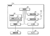
図2は車載機11aの要部構成を示すブロック図である。車載機11aは、無線送信部30、無線受信部31、入力部32、駆動部33、記憶部34及び制御部35を有する。無線送信部30、無線受信部31、入力部32、駆動部33及び記憶部34は、制御部35に各別に接続されている。入力部32は更にセンサ20に接続されている。駆動部33は駆動対象21に接続されている。センサ20及び駆動対象21も車両2に搭載されている。
FIG. 2 is a block diagram showing a main configuration of the in-
センサ20は、車両2の速度若しくは加速度、又は、車両2の外側の明るさ等を検出する。センサ20は、検出した検出値を示すセンサ情報を入力部32に出力する。入力部32に入力されたセンサ情報は、制御部35によって取得される。制御部35が入力部32から取得したセンサ情報が示す検出値は、取得時点においてセンサ20が検出した検出値と略一致している。
The
駆動対象21はランプ又はモータ等の電気機器である。駆動部33は、制御部35の指示に従って、駆動対象21の駆動と、該駆動の停止とを行う。
無線送信部30は、制御部35の指示に従って、応答信号を通信装置10に送信する。
無線受信部31は指示信号を受信する。
記憶部34には制御プログラムP1が記憶されている。
The
The
The
The
制御部35は、CPU(Central Processing Unit)を有し、制御プログラムP1を実行することによって、駆動対象21を駆動する駆動処理、駆動対象21の駆動を停止する停止処理、及び、センサ情報を取得する取得処理を実行する。
The
制御部35は、無線受信部31が、駆動対象21の駆動を指示する指示信号を受信した場合に駆動処理を実行する。駆動処理では、制御部35は、駆動部33に指示して、駆動対象21を駆動させる。次に、制御部35は、無線送信部30に指示して、駆動対象21が駆動したことを示す応答信号を通信装置10に送信し、駆動処理を終了する。
The
制御部35は、無線受信部31が、駆動対象21の駆動の停止を指示する指示信号を受信した場合に停止処理を実行する。停止処理では、制御部35は、駆動部33に指示して、駆動対象21の駆動を停止させる。次に、制御部35は、無線送信部30に指示して、駆動対象21の駆動が停止したことを示す応答信号を通信装置10に送信し、停止処理を終了する。
The
制御部35は、無線受信部31が、センサ情報の取得を指示する指示信号を受信した場合に取得処理を実行する。取得処理では、制御部35は、入力部32からセンサ情報を取得する。次に、制御部35は、無線送信部30に指示して、入力部32から取得したセンサ情報を含む応答信号を通信装置10に送信し、取得処理を終了する。
The
車載機11b,11c,11d夫々にも、車両2に搭載されているセンサ20及び駆動対象21が接続されている。車載機11b,11c,11d夫々は車載機11aと同様に構成されている。このため、これらの詳細な説明を省略する。
なお、車載機11a,11b,11c,11d夫々に接続されているセンサ20は相互に異なり、車載機11a,11b,11c,11d夫々に接続されている駆動対象21も相互に異なる。
A
The
図3は検出装置12aの要部構成を示すブロック図である。検出装置12aは、無線送信部40、無線受信部41、圧力検出部42、記憶部43及び制御部44を有する。無線送信部40、無線受信部41、圧力検出部42及び記憶部43は、制御部44に各別に接続されている。
無線送信部40は、制御部44の指示に従って、空気圧信号を無線で通信装置10に無線で送信する。
無線受信部41は空気圧要求信号を無線で受信する。無線受信部41は第2の受信部として機能する。
圧力検出部42は、制御部44の指示に従って、検出装置12aに対応する車両2のタイヤの空気圧を検出する。
記憶部43には制御プログラムP2が記憶されている。
FIG. 3 is a block diagram showing a main configuration of the
The
The
The
The
制御部44は、CPUを有し、制御プログラムP2を実行することによって、種々の処理を実行する。具体的には、制御部44は、無線受信部41が空気圧要求信号を受信した場合、圧力検出部42に指示して、車両2のタイヤの空気圧を検出させる。次に、制御部44は、無線送信部40に指示して、圧力検出部42が検出した空気圧を示す空気圧信号を通信装置10に送信させる。空気圧信号は特定の信号に相当し、無線送信部40は第2の送信部として機能する。
The
検出装置12b,12c,12d夫々は、検出装置12aと同様に構成されている。このため、これらの詳細な説明を省略する。
なお、検出装置12b,12c,12d夫々の圧力検出部42は、検出装置12aに対応するタイヤではなく、自身を有する検出装置に対応するタイヤの空気圧を検出する。
Each of the
In addition, each
図4は通信装置10の要部構成を示すブロック図である。通信装置10は、無線送信部50、無線受信部51、有線通信部52、通知部53、記憶部54、制御部55及び受信アンテナRtを有する。無線送信部50、無線受信部51、有線通信部52、通知部53及び記憶部54は、制御部55に各別に接続されている。無線送信部50は、更に、4つの送信アンテナTa,Tb,Tc,Tdに各別に接続されている。無線受信部51は、更に、受信アンテナRtに接続されている。有線通信部52は、更に、車両2内に設置された通信線L1に接続されている。通信線L1には、有線通信部52の他に、種々の装置が接続されている。
FIG. 4 is a block diagram showing a main configuration of the
無線送信部50は、制御部55の指示に従って、4つの送信アンテナTa,Tb,Tc,Td中の少なくとも1つから、信号を、車載機11a,11b,11c,11d夫々の無線受信部31と、検出装置12a,12b,12c,12d夫々の無線受信部41と、無線端末13とに無線で送信する。無線送信部50は前述した指示信号及び空気圧要求信号を送信する。
車載機11a,11b,11c,11d夫々は対象に相当し、検出装置12a,12b,12c,12d夫々は第2の対象に相当する。
The
Each of the vehicle-mounted
無線受信部51は、受信アンテナRtを介して信号を無線で受信する。無線受信部51は前述した応答信号及び空気圧信号を受信する。
The
有線通信部52は、通信線L1を介して、車載機11a,11b,11c,11dの少なくとも1つに種々の動作を要求する動作要求信号と、車両2のイグニッションスイッチがオン又はオフに切替わったことを示すイグニション信号とを受信する。動作要求信号は、車載機11aに接続されている駆動対象21の駆動、若しくは、該駆動の停止を要求する信号、又は、車載機11bに接続されているセンサ20のセンサ情報の取得を要求する信号である。イグニション信号は、イグニッションスイッチがオン又はオフに切替わる都度、有線通信部52に送信される。また、有線通信部52は、制御部55の指示に従って、通信線L1を介して信号を送信する。
In the
図5は通知部53の動作の説明図である。通知部53には、ハイレベル電圧及びローレベル電圧によって構成されるクロック信号が入力されている。図5にはクロック信号の波形が示されている。図5において、「H」はハイレベル電圧を示し、「L」はローレベル電圧を示す。クロック信号では、一定の周期で、電圧がローレベル電圧からハイレベル電圧に遷移する。
FIG. 5 is an explanatory diagram of the operation of the
通知部53は、タイヤの空気圧の確認を指示する確認信号を制御部55に出力する。通知部53は、更に、確認信号の出力を事前に通知する事前信号も制御部55に出力する。図5には、通知部53が確認信号を制御部53に出力する出力タイミングと、通知部53が事前信号を制御部53に出力する出力タイミングとが示されている。
図5に示すように、通知部53は、クロック信号のN周期(N:2以上の整数)が経過する都度、確認信号を制御部55に出力する。また、通知部53は、確認信号を出力してから、クロック信号のK周期(K:N未満である自然数)が経過した場合、事前信号を制御部55に出力する。
図5には、Nが5であり、かつ、Kが4である例が示されている。当然のことながら、Nは5に限定されず、Kは4に限定されない。
The
As shown in FIG. 5, the
FIG. 5 shows an example in which N is 5 and K is 4. Of course, N is not limited to 5, and K is not limited to 4.
記憶部54には制御プログラムP3が記憶されている。記憶部54には、更に、フラグの値が記憶されている。フラグの値は制御部55によってゼロ又は1に設定される。
制御部55は、CPUを有し、制御プログラムP3を実行することによって、タイヤの空気圧を確認する前に実行する事前処理、タイヤの空気圧を確認する確認処理、車載機11a,11b,11c,11dの少なくとも1つの動作を制御する制御処理、及び、無線端末13の位置を特定する特定処理を実行する。
The
The
図6は事前処理の手順を示すフローチャートである。制御部55には通知部53から事前信号及び確認信号が入力される。制御部55は、通知部53から事前信号が入力された場合に事前処理を実行する。まず、制御部55は、有線通信部52が受信した最新のイグニション信号が示す内容に基づいて、車両2のイグニッションスイッチがオンであるか否かを判定する(ステップS1)。
FIG. 6 is a flowchart showing the pre-processing procedure. A prior signal and a confirmation signal are input to the
ステップS1では、制御部55は、最新のイグニション信号によってイグニッションスイッチがオンに切替わったことが示されている場合、イグニッションスイッチがオンであると判定する。また、制御部55は、最新のイグニション信号によってイグニッションスイッチがオフに切替わったことが示されている場合、イグニッションスイッチがオフであると判定する。
In step S1, the
制御部55は、イグニッションスイッチがオンであると判定した場合(S1:YES)、フラグの値を1に設定する(ステップS2)。制御部55は、イグニッションスイッチがオンではない、即ち、イグニッションスイッチがオフであると判定した場合(S1:NO)、又は、ステップS2を実行した後、事前処理を終了する。
When it is determined that the ignition switch is on (S1: YES), the
図7は確認処理の手順を示すフローチャートである。制御部55は、通知部53から確認信号が入力された場合に確認処理を実行する。まず、制御部55は、事前処理のステップS1と同様に、イグニッションスイッチがオンであるか否かを判定する(ステップS11)。
FIG. 7 is a flowchart showing the procedure of the confirmation process. The
制御部55は、イグニッションスイッチがオンであると判定した場合(S11:YES)、無線送信部50に指示して、送信アンテナTa,Tb,Tc,Td中の少なくとも1つ、例えば、送信アンテナTb,Tcから空気圧要求信号を4つの検出装置12a,12b,12c,12dに送信させる(ステップS12)。検出装置12a,12b,12c,12d夫々では、無線受信部41が空気圧要求信号を受信した場合、制御部44は空気圧の検出に係る前述の処理を実行する。この処理では、圧力検出部42はタイヤの空気圧を検出し、無線送信部40は圧力検出部42が検出した空気圧を示す空気圧信号を通信装置10の無線受信部51に無線で送信する。
When the
前述したように、通知部53は、クロック信号のN周期が経過する都度、確認信号を制御部55に出力し、制御部55は、通知部53から確認信号が入力される都度、確認処理を実行する。確認処理では、イグニッションスイッチがオンである場合、ステップS12が実行される。このため、イグニッションスイッチがオンである場合においては、制御部55は、ステップS12を繰り返し実行し、無線送信部50は、4つの検出装置12a,12b,12c,12dに要求信号を繰り返し送信する。
As described above, the
制御部55は、ステップS12を実行した後、無線受信部51が、検出装置12a,12b,12c,12d夫々の無線送信部40から4つの空気圧信号を受信したか否かを判定する(ステップS13)。制御部55は、無線受信部51が4つの空気圧信号を受信していないと判定した場合(S13:NO)、ステップS13を再び実行し、無線受信部51が4つの空気圧信号を受信するまで待機する。
After executing Step S12, the
制御部55は、無線受信部51が4つの空気圧信号を受信したと判定した場合(S13:YES)、4つの空気圧信号夫々が示す4つの空気圧が正常であるか否かを判定する(ステップS14)。ステップS14では、制御部55は、4つの空気圧の全てが、予め設定されている基準値以上である場合、4つの空気圧は正常であると判定する。制御部55は、4つの空気圧中の少なくとも1つが基準値未満である場合、4つの空気圧は正常ではないと判定する。基準値は記憶部54に記憶されている。
When it is determined that the
なお、4つの空気圧の判定に用いる4つの基準値は同一でなくてもよい。例えば、車両2の前方に配置されている2つのタイヤの空気圧の判定に用いる基準値として、同一の第1基準値が用いられ、車両2の後方に配置されている2つのタイヤの空気圧の判定に用いる基準値として、同一の第2基準値が用いられ、第1基準値及び第2基準値が互いに異なっていてもよい。
The four reference values used for the determination of the four air pressures may not be the same. For example, the same first reference value is used as a reference value used to determine the air pressure of two tires arranged in front of the
制御部55は、4つの空気圧が正常ではないと判定した場合(S14:NO)、有線通信部52に指示して、4つの空気圧中の少なくとも1つが異常であることを報知する報知信号を、通信線L1を介して送信させる(ステップS15)。報知信号を受信した装置では、図示しないランプの点灯、又は、図示しない表示部へのメッセージの表示等が行われ、空気圧の異常が報知される。
When the
制御部55は、4つの空気圧が正常であると判定した場合(S14:YES)、又は、ステップS15を実行した後、フラグの値をゼロに設定する(ステップS16)。制御部55は、イグニッションスイッチがオフであると判定した場合(S11:NO)、又は、ステップS16を実行した後、確認処理を終了する。
When it is determined that the four air pressures are normal (S14: YES), or after executing Step S15, the
以上のように、事前処理においてフラグの値が1に設定され、確認処理においてフラグの値がゼロに設定される。イグニッションスイッチがオンである場合においては、フラグの値がゼロであることは、現在の時点が、確認処理が終了してから事前処理が開始されるまでの期間中の時点であることを示し、フラグの値が1であることは、現在の時点が、事前処理が開始されてから確認処理が終了するまでの期間中の時点であることを示す。 As described above, the flag value is set to 1 in the preliminary process, and the flag value is set to zero in the confirmation process. When the ignition switch is on, a flag value of zero indicates that the current time is a time during the period from the end of the confirmation process to the start of pre-processing, A flag value of 1 indicates that the current time point is a time point in the period from the start of the pre-processing to the end of the confirmation processing.
図8は制御処理の手順を示すフローチャートである。通信装置10の制御部55は、有線通信部52が動作要求信号を受信した場合に制御処理を実行する。まず、制御部55は、フラグの値がゼロであるか否かを判定する(ステップS21)。制御部55は、フラグの値がゼロであると判定した場合(S21:YES)、有線通信部52が受信した動作要求信号に基づいて、4つの車載機11a,11b,11c,11dの中から、無線で指示信号を送信する車載機を決定する(ステップS22)。制御部55は決定部として機能する。
FIG. 8 is a flowchart showing the procedure of the control process. The
一例として、車載機11aに接続されている駆動対象21がパワーウィンドウを開閉するモータである場合において、動作要求信号がパワーウィンドウの開放を要求する信号であるとき、制御部55は、指示信号を送信する車載機として車載機11aを決定する。また、他例として、車載機11bに接続されているセンサ20が車速を検出するように構成されている場合において、動作要求信号が車速を示すセンサ情報の取得を要求する信号であるとき、制御部55は、指示信号を送信する車載機として車載機11bを決定する。
As an example, when the
次に、制御部55は、送信アンテナTa,Tb,Tc,Tdの中から、ステップS22で決定した車載機に対応する送信アンテナを選択する(ステップS23)。4つの車載機11a,11b,11c,11d夫々には、4つの送信アンテナTa,Tb,Tc,Td中の1つが予め対応付けられている。記憶部54には、車載機11a,11b,11c,11dと送信アンテナTa,Tb,Tc,Tdとの対応関係が記憶されている。
Next, the
図9は、車載機11a,11b,11c,11dと送信アンテナTa,Tb,Tc,Tdとの対応関係を示す図表である。図9に示すように、車載機11a,11b,11c,11d夫々は送信アンテナTa,Tb,Tc,Tdに対応している。車載機11a,11b,11c,11d夫々には、送信アンテナTa,Tb,11c,11dの中で、最も近い送信アンテナが対応している。この対応関係が記憶部54に記憶されている。具体的には、車載機11a,11b,11c,11d夫々を示す情報が、送信アンテナTa,Tb,Tc,Td夫々を示す情報中の1つに対応付けられている。ステップS23では、記憶部54に記憶されている対応関係に基づいて、送信アンテナTa,Tb,Tc,Tdの中から送信アンテナを選択する。
FIG. 9 is a chart showing a correspondence relationship between the vehicle-mounted
次に、制御部55は、無線送信部50に指示して、ステップS23で選択した送信アンテナから、ステップS22で決定した車載機に指示信号を送信させる(ステップS24)。指示信号の内容は、有線通信部52が受信した動作要求信号の内容に基づく。動作要求信号が駆動対象21の駆動、又は、該駆動の停止を要求する信号である場合、指示信号は、駆動対象21の駆動、又は、該駆動の停止を指示する信号である。動作要求信号がセンサ情報の取得を要求する信号である場合、指示信号は、センサ情報の取得を指示する信号である。
Next, the
前述したように、車載機11a,11b,11c,11d夫々では、無線受信部31が、駆動対象21の駆動を指示する指示信号を受信した場合、制御部35は駆動処理を実行する。駆動部33は、駆動対象21を駆動し、無線送信部30は、駆動対象21の駆動を示す応答信号を通信装置10の無線受信部51に無線で送信する。
As described above, in each of the in-
また、無線受信部31が、駆動対象21の駆動の停止を指示する指示信号を受信した場合、制御部35は停止処理を実行する。駆動部33は駆動対象21の駆動を停止する。駆動部33は、駆動対象21の駆動を停止し、無線送信部30は、駆動対象21の駆動の停止を示す応答信号を通信装置10の無線受信部51に無線で送信する。
In addition, when the
更に、無線受信部31が、センサ20のセンサ情報の取得を指示する指示信号を受信した場合、制御部55は、取得処理を実行し、センサ20から入力部32に入力されたセンサ情報を取得する。無線送信部30は、制御部55が取得したセンサ情報を含む応答信号を通信装置10の無線受信部51に無線で送信する。
Further, when the
制御部55は、ステップS24を実行した後、無線受信部51が応答信号を受信したか否かを判定する(ステップS25)。制御部55は、無線受信部51が応答信号を受信しなかったと判定した場合(S25:NO)、ステップS25を再び実行し、無線受信部51が応答信号を受信するまで待機する。
After executing Step S24, the
制御部55は、フラグの値がゼロではない、即ち、フラグの値が1であると判定した場合(S21:NO)、又は、無線受信部51が応答信号を受信したと判定した場合(S25:YES)、制御処理を終了する。
制御部55は、無線受信部51が受信した応答信号に基づいて種々の処理を実行する。応答信号にセンサ情報が含まれている場合、例えば、制御部55は、有線通信部52に指示して、センサ情報を含む信号を、通信線L1を介して送信させる。これにより、センサ情報の取得を要求する動作要求信号を送信した装置にセンサ情報が通知される。
The
The
なお、制御処理のステップS22で制御部55が決定する車載機の数は、1つに限定されず、2以上であってもよい。この場合、ステップS23では、制御部55は、ステップS22で決定した複数の車載機夫々に対応する一又は複数の送信アンテナを選択する。ステップS24では、制御部55は、無線送信部50に指示して、指示信号を、ステップS23で選択した一又は複数の送信アンテナからを無線で送信させる。ステップS25では、制御部55は、無線受信部51が、ステップS22で決定した複数の車載機の全てから応答信号を受信したか否かを判定する。
Note that the number of in-vehicle devices determined by the
通信装置10の有線通信部52は、通信線L1を介して、無線端末13の位置の特定を指示する特定信号を受信する。制御部55は、有線通信部52が特定信号を受信した場合、特定処理を実行する。特定処理では、制御部55は、フラグの値が1である場合、無線端末13の位置を特定することはない。また、制御部55は、フラグの値がゼロである場合、無線送信部50に信号を無線で無線端末13に送信させ、無線受信部51が無線端末13から受信したか否かに基づいて、無線端末13の位置を特定する。
The
例えば、制御部55は、無線送信部50に指示して、送信アンテナTdから信号を無線端末13に送信させる。この送信によって、無線受信部51が無線端末13から信号を受信した場合、制御部55は無線端末13が車両2内に位置していると判定する。制御部55は、無線受信部51が無線端末13から信号を受信しなかった場合、無線送信部50に指示して、送信アンテナTb,Tcから信号を無線端末13に送信させる。この送信によって、無線受信部51が無線端末13から信号を受信した場合、制御部55は無線端末13が車両2の外側近傍に位置していると判定する。制御部55は、無線受信部51が無線端末13から信号を受信しなかった場合、無線端末13は車両2から十分に離れた場所に位置していると判定する。無線端末13の位置に関するこの判定結果に基づいて、車両2のエンジンの始動若しくは停止、又は、車両2の開閉等が行われる。
For example, the
通信システム1では、4つの車載機11a,11b,11c,11d夫々を通信装置10に有線で接続する必要がない。このため、通信システム1の重量が軽く、通信システム1の製造費用が安価である。また、配線が不要であるため、車載機の増設が容易である。また、通信装置10が4つの車載機11a,11b,11c,11d中の1つの車載機に信号を送信するとき、4つの送信アンテナTa,Tb,Tc,Tdの中で該車載機に最も近い送信アンテナが用いられるので、信号の送信距離が最短である。このため、通信システム1では低消費電力が実現される。
In the
また、制御処理では、通信装置10の制御部55は、フラグの値が1である場合、ステップS24を実行することはなく、無線送信部50は指示信号を車載機11a,11b,11c,11dに無線で送信することはない。言い換えると、イグニッションスイッチがオンである場合において、事前処理が開始されてから、確認処理が終了するまでの期間、無線送信部50は、車載機11a,11b,11c,11dへの指示信号の送信を停止している。この期間には、通信装置10の無線送信部50が空気圧要求信号を送信してから、無線受信部51が空気圧信号を受信するまでの期間が含まれる。
In the control process, when the value of the flag is 1, the
通信装置10の制御部55は、確認処理を実行していない間、即ち、通信装置10が検出装置12a,12b,12c,12d夫々と通信していない間に制御処理を実行し、無線送信部50は車載機11a,11b,11c,11dに指示信号を無線で送信する。
The
タイヤの空気圧は、車両2の安全な走行を実現するために必要なパラメータである。このため、タイヤの空気圧を確認する確認処理は、通信装置10の通知部53が確認信号を制御部55に出力した場合に、制御部55によって確実に実行されることが好ましい。
The tire air pressure is a parameter necessary for realizing safe traveling of the
通信システム1では、通知部53が事前信号を出力してから確認信号を出力するまでの期間は、制御部55が制御処理にかかる最大時間よりも長く、かつ、特定処理にかかる最大時間よりも長い。このため、通知部53が事前信号を制御部55に出力する直前に、有線通信部52が動作要求信号又は特定信号を受信した場合であっても、確認信号が通知部53から出力された時点で確認処理が確実に実行される。
通信装置10の制御部55は、車両2の4つのタイヤの空気圧を監視しつつ、無線送信部50に指示して、4つの車載機11a,11b,11c,11dへの指示信号を送信させる。
In the
The
なお、通信システム1が備える検出装置の数は4つに限定されない。検出装置の数は車両2のタイヤの数と同じである。従って、車両2が備えるタイヤの数に応じて検出装置の数も変更される。更に、検出装置は、タイヤの空気圧を検出する装置に限定されず、通信装置10と繰り返し通信する装置であればよい。この場合、検出装置の数は、1,2,3又は5以上であってもよい。検出装置は、例えば、車両2のラジエーター内を流れる水温を検出する装置であってもよい。
Note that the number of detection devices included in the
また、記憶部54に記憶されている対応関係について、車載機11a,11b,11c,11dの対応付けを、距離ではなく、送信アンテナTa,Tb,Tc,Tdから受信した受信強度に基づいて行ってもよい。車載機11a,11b,11c,11d夫々について、例えば、送信アンテナTa,Tb,Tc,Td夫々から強度が同一である信号を送信した場合に、無線受信部31が受信した信号の強度が最大である送信アンテナを対応付けてもよい。
更に、車載機11a,11b,11c,11d夫々に対応する送信アンテナは相互に異なっていなくてもよい。例えば、車載機11a,11b夫々に送信アンテナTaが対応していてもよい。
In addition, regarding the correspondence relationship stored in the
Furthermore, the transmission antennas corresponding to the
また、車載機11a,11b,11c,11d夫々にセンサ20及び駆動対象21の両方が接続されていなくてもよい。車載機11a,11b,11c,11d夫々には、センサ20及び駆動対象21中の少なくとも1つが接続されていればよい。
更に、通信システム1が備える車載機及び送信アンテナ夫々の数は、4つに限定されず、2、3、又は、5以上であってもよい。更に、車載機の数と送信アンテナの数とは異なっていてもよい。
Moreover, both the
Furthermore, the number of each of the in-vehicle device and the transmission antenna included in the
また、通信装置10の通知部53が制御部55に確認信号を周期的に出力しなくてもよい。通知部53は確認信号を繰り返し送信するように構成されていればよい。
In addition, the
開示された本実施の形態は、全ての点で例示であって制限的なものではないと考えられるべきである。本発明の範囲は上述の説明ではなくて特許請求の範囲によって示され、特許請求の範囲と均等の意味及び範囲内での全ての変更が含まれることが意図される。 The disclosed embodiment should be considered as illustrative in all points and not restrictive. The scope of the present invention is defined by the terms of the claims, rather than the description above, and is intended to include any modifications within the scope and meaning equivalent to the terms of the claims.
1 通信システム
10 通信装置
11a,11b,11c,11d 車載機(対象)
12a,12b,12c,12d 検出装置(第2の対象)
40 無線送信部(第2の送信部)
41 無線受信部(第2の受信部)
42 圧力検出部
50 無線送信部
51 無線受信部
55 制御部(決定部)
Ta,Tb,Tc,Td 送信アンテナ
DESCRIPTION OF
12a, 12b, 12c, 12d detection device (second object)
40 Wireless transmission unit (second transmission unit)
41 Wireless receiver (second receiver)
42
Ta, Tb, Tc, Td Transmit antenna
Claims (4)
前記通信装置は、前記複数の対象の中から、無線で信号を送信する対象を決定する決定部を有し、
前記複数の対象夫々には、前記複数のアンテナ中の1つが予め対応付けられており、
前記送信部は、前記決定部が決定した対象に対応する前記アンテナから該対象に信号を送信すること
を特徴とする通信システム。 In a communication system including a communication device having a transmission unit that wirelessly transmits signals from a plurality of antennas, and a plurality of targets to which signals are transmitted by the transmission unit,
The communication apparatus includes a determination unit that determines a target to wirelessly transmit a signal from among the plurality of targets.
Each of the plurality of objects is associated in advance with one of the plurality of antennas,
The transmission unit transmits a signal to the target from the antenna corresponding to the target determined by the determination unit.
前記通信装置は無線で信号を受信する受信部を有し、
前記送信部は、前記複数のアンテナの少なくとも1つから信号の送信を要求する要求信号を前記第2の対象に繰り返し送信し、
前記第2の対象は、
前記要求信号を無線で受信する第2の受信部と、
該第2の受信部が前記要求信号を受信した場合に特定の信号を前記受信部に送信する第2の送信部と
を有し、
前記送信部は、前記要求信号を送信してから、前記受信部が前記特定の信号を受信するまでの間、前記複数の対象への信号の送信を停止していること
を特徴とする請求項1に記載の通信システム。 A second object to which a signal is transmitted by the transmitter;
The communication device has a receiving unit for receiving a signal wirelessly,
The transmitter repeatedly transmits a request signal requesting transmission of a signal from at least one of the plurality of antennas to the second target;
The second object is:
A second receiver for wirelessly receiving the request signal;
A second transmitter that transmits a specific signal to the receiver when the second receiver receives the request signal;
The transmission unit stops transmission of signals to the plurality of targets from when the request signal is transmitted until the reception unit receives the specific signal. The communication system according to 1.
前記特定の信号は、該検出部が検出した空気圧を示す信号であること
を特徴とする請求項2に記載の通信システム。 The second object has a detection unit that detects a tire pressure of a vehicle when the second reception unit receives the request signal,
The communication system according to claim 2, wherein the specific signal is a signal indicating an air pressure detected by the detection unit.
前記複数の対象の中から、無線で信号を送信する対象を決定する決定部を備え、
前記複数の対象夫々には、前記複数のアンテナ中の1つが予め対応付けられており、
前記送信部は、前記決定部が決定した対象に対応する前記アンテナから該対象に信号を送信すること
を特徴とする通信装置。 In a communication device including a transmission unit that wirelessly transmits signals from a plurality of antennas to a plurality of targets,
A determination unit that determines a target to transmit a signal wirelessly from among the plurality of targets,
Each of the plurality of objects is associated in advance with one of the plurality of antennas,
The transmission unit transmits a signal to the target from the antenna corresponding to the target determined by the determination unit.
Priority Applications (4)
| Application Number | Priority Date | Filing Date | Title |
|---|---|---|---|
| JP2016049875A JP6572808B2 (en) | 2016-03-14 | 2016-03-14 | Communication system and communication apparatus |
| US16/081,776 US10266018B2 (en) | 2016-03-14 | 2017-02-22 | Communication system and communication apparatus |
| PCT/JP2017/006554 WO2017159250A1 (en) | 2016-03-14 | 2017-02-22 | Communication system and communication apparatus |
| CN201780014670.0A CN108781088A (en) | 2016-03-14 | 2017-02-22 | Communication system and communication device |
Applications Claiming Priority (1)
| Application Number | Priority Date | Filing Date | Title |
|---|---|---|---|
| JP2016049875A JP6572808B2 (en) | 2016-03-14 | 2016-03-14 | Communication system and communication apparatus |
Publications (3)
| Publication Number | Publication Date |
|---|---|
| JP2017165146A true JP2017165146A (en) | 2017-09-21 |
| JP2017165146A5 JP2017165146A5 (en) | 2018-08-30 |
| JP6572808B2 JP6572808B2 (en) | 2019-09-11 |
Family
ID=59851443
Family Applications (1)
| Application Number | Title | Priority Date | Filing Date |
|---|---|---|---|
| JP2016049875A Active JP6572808B2 (en) | 2016-03-14 | 2016-03-14 | Communication system and communication apparatus |
Country Status (4)
| Country | Link |
|---|---|
| US (1) | US10266018B2 (en) |
| JP (1) | JP6572808B2 (en) |
| CN (1) | CN108781088A (en) |
| WO (1) | WO2017159250A1 (en) |
Citations (3)
| Publication number | Priority date | Publication date | Assignee | Title |
|---|---|---|---|---|
| JP2004203225A (en) * | 2002-12-25 | 2004-07-22 | Pacific Ind Co Ltd | Monitor for tire condition |
| JP2005207223A (en) * | 2003-12-25 | 2005-08-04 | Omron Corp | Remote control system for vehicle and tire pneumatic pressure monitoring system |
| JP2008168826A (en) * | 2007-01-12 | 2008-07-24 | Honda Motor Co Ltd | Tire pneumatic pressure monitoring system |
Family Cites Families (5)
| Publication number | Priority date | Publication date | Assignee | Title |
|---|---|---|---|---|
| JP3201155B2 (en) * | 1994-07-20 | 2001-08-20 | 株式会社デンソー | Moving object identification device |
| JP4270284B2 (en) * | 2007-01-30 | 2009-05-27 | トヨタ自動車株式会社 | Wheel state monitoring system and wheel state detection device |
| CN103770741A (en) * | 2012-10-24 | 2014-05-07 | 联创汽车电子有限公司 | Passive entry passive start and tire pressure monitoring system |
| JP2015064764A (en) | 2013-09-25 | 2015-04-09 | 株式会社オートネットワーク技術研究所 | In-vehicle device |
| CN104924862A (en) * | 2014-03-21 | 2015-09-23 | 同致电子企业股份有限公司 | Passive triggered tire pressure monitoring system and method |
-
2016
- 2016-03-14 JP JP2016049875A patent/JP6572808B2/en active Active
-
2017
- 2017-02-22 WO PCT/JP2017/006554 patent/WO2017159250A1/en active Application Filing
- 2017-02-22 CN CN201780014670.0A patent/CN108781088A/en active Pending
- 2017-02-22 US US16/081,776 patent/US10266018B2/en active Active
Patent Citations (3)
| Publication number | Priority date | Publication date | Assignee | Title |
|---|---|---|---|---|
| JP2004203225A (en) * | 2002-12-25 | 2004-07-22 | Pacific Ind Co Ltd | Monitor for tire condition |
| JP2005207223A (en) * | 2003-12-25 | 2005-08-04 | Omron Corp | Remote control system for vehicle and tire pneumatic pressure monitoring system |
| JP2008168826A (en) * | 2007-01-12 | 2008-07-24 | Honda Motor Co Ltd | Tire pneumatic pressure monitoring system |
Also Published As
| Publication number | Publication date |
|---|---|
| JP6572808B2 (en) | 2019-09-11 |
| CN108781088A (en) | 2018-11-09 |
| WO2017159250A1 (en) | 2017-09-21 |
| US10266018B2 (en) | 2019-04-23 |
| US20190061442A1 (en) | 2019-02-28 |
Similar Documents
| Publication | Publication Date | Title |
|---|---|---|
| JP6331679B2 (en) | Tire pressure detector | |
| JP6547714B2 (en) | Tire pressure monitoring system | |
| JP2017074878A (en) | On-vehicle storage device and on-vehicle storage system | |
| JP2013028251A (en) | Tire pneumatic monitoring device and trigger device | |
| JP5405560B2 (en) | Method for wirelessly monitoring tire pressure, wireless tire pressure monitoring system and system component | |
| KR102367908B1 (en) | Universal tire pressure sensor | |
| JP2007302188A (en) | Tire air pressure detection device | |
| US9813119B1 (en) | Passive wireless accessory switch pack | |
| KR101565344B1 (en) | A vehicle interconnection terminal illumination control system and a control method | |
| JP2012252462A (en) | Wheel position detection device and tire pressure detection device provided with the same | |
| JP6572808B2 (en) | Communication system and communication apparatus | |
| JP2012171449A (en) | Electronic control device and failure diagnosis information transmission method in failure diagnosis system of vehicle | |
| JP2006242707A (en) | Tire air pressure detection device | |
| KR101365925B1 (en) | Identification Device For Tire Pressure Sensing Module | |
| US10065460B2 (en) | Method for monitoring an air pressure in at least one tyre of a motor vehicle | |
| JP2010144352A (en) | Battery warning system for vehicle keyless device | |
| US20110205046A1 (en) | Tire detection apparatus | |
| WO2016148039A1 (en) | Air pressure observation system and tire air pressure detection device | |
| JP2015229434A (en) | Tire condition monitoring device | |
| JP4321351B2 (en) | Tire condition monitoring system | |
| KR20110021457A (en) | Wireless control system and method of a trailer taillight | |
| JP2011126371A (en) | Tire air pressure monitoring system and tire air pressure detection method | |
| JP6593285B2 (en) | Tire pressure monitoring system | |
| CN106985822A (en) | For the method and apparatus for the starter motor for assessing internal combustion engine | |
| WO2013094417A1 (en) | Vehicle security device |
Legal Events
| Date | Code | Title | Description |
|---|---|---|---|
| A621 | Written request for application examination |
Free format text: JAPANESE INTERMEDIATE CODE: A621 Effective date: 20180628 |
|
| A521 | Request for written amendment filed |
Free format text: JAPANESE INTERMEDIATE CODE: A523 Effective date: 20180719 |
|
| A131 | Notification of reasons for refusal |
Free format text: JAPANESE INTERMEDIATE CODE: A131 Effective date: 20190528 |
|
| A521 | Request for written amendment filed |
Free format text: JAPANESE INTERMEDIATE CODE: A523 Effective date: 20190709 |
|
| TRDD | Decision of grant or rejection written | ||
| A01 | Written decision to grant a patent or to grant a registration (utility model) |
Free format text: JAPANESE INTERMEDIATE CODE: A01 Effective date: 20190716 |
|
| A61 | First payment of annual fees (during grant procedure) |
Free format text: JAPANESE INTERMEDIATE CODE: A61 Effective date: 20190729 |
|
| R150 | Certificate of patent or registration of utility model |
Ref document number: 6572808 Country of ref document: JP Free format text: JAPANESE INTERMEDIATE CODE: R150 |