JP2017164483A - Game machine - Google Patents
Game machine Download PDFInfo
- Publication number
- JP2017164483A JP2017164483A JP2016257353A JP2016257353A JP2017164483A JP 2017164483 A JP2017164483 A JP 2017164483A JP 2016257353 A JP2016257353 A JP 2016257353A JP 2016257353 A JP2016257353 A JP 2016257353A JP 2017164483 A JP2017164483 A JP 2017164483A
- Authority
- JP
- Japan
- Prior art keywords
- game
- special symbol
- jackpot
- gaming state
- mpu
- Prior art date
- Legal status (The legal status is an assumption and is not a legal conclusion. Google has not performed a legal analysis and makes no representation as to the accuracy of the status listed.)
- Withdrawn
Links
Images


Abstract
Description
本発明は、パチンコ機に代表される遊技機に関するものである。 The present invention relates to a gaming machine represented by a pachinko machine.
パチンコ機等の遊技機には、始動入賞口への遊技球の入賞に基づいて行われる抽選の結果が当たりだった場合に、当たり状態へと移行するものがある。かかる遊技機の中には、当たり状態の終了を契機として、当たり状態が通常の確率で抽選される通常状態と、当たり状態が通常状態よりも高い確率で抽選される確率変動状態とのいずれかに設定されるものがある。 Some gaming machines such as pachinko machines shift to a winning state when the result of a lottery performed based on the winning of a game ball at the start winning opening is a win. Among such gaming machines, one of a normal state in which the winning state is drawn with a normal probability and a probability fluctuation state in which the winning state is drawn with a higher probability than the normal state, triggered by the end of the winning state Some are set to.
しかしながら、上述した従来の遊技機では、当たり状態の終了を契機に通常状態が設定された場合に、確率変動状態よりも低い抽選確率で当たり状態が抽選される不利な状態が、少なくとも次に当たり状態となるまで続いてしまうため、通常状態となった場合に遊技者の遊技に対する興趣の向上を図ることができないという問題点があった。 However, in the conventional gaming machine described above, when the normal state is set at the end of the hit state, the disadvantageous state in which the win state is drawn with a lottery probability lower than the probability variation state is at least the next hit state Therefore, there is a problem that it is not possible to improve the interest of the player in the game in the normal state.
本発明は、上記例示した問題点を解決するためになされたものであり、遊技者の遊技に対する興趣を向上させることができる遊技機を提供することを目的とする。 The present invention has been made to solve the above-described problems, and an object of the present invention is to provide a gaming machine that can improve the interest of a player in games.
この目的を達成するために請求項1記載の遊技機は、判別条件の成立に基づいて判別を実行する判別手段と、その判別手段による判別で特定の判別結果となったことに基づいて遊技者に有利な特典遊技を実行する特典遊技実行手段と、前記特典遊技の実行中に遊技球が入球可能となる特定領域と、1の前記特典遊技において前記特定領域へと遊技球が入球した場合に、前記特典遊技の実行が終了した後の遊技状態として第1遊技状態を設定し、1の前記特典遊技において前記特定領域へと遊技球が入球しなかった場合に、前記第1遊技状態とは異なる第2遊技状態を設定する遊技状態設定手段と、前記特典遊技実行手段により実行される特典遊技の種別として、第1特典遊技を少なくとも含む複数の特典遊技の種別の中から1の種別を決定する種別決定手段と、前記第1特典遊技の実行中に前記特定領域へと遊技球が入球したことに基づいて設定される前記第1遊技状態の有利度合を、前記第1特典遊技の実行中に前記特定領域へと遊技球が入球しなかったことに基づいて設定される前記第2遊技状態の有利度合い以下に設定する有利度合設定手段とを備える。
In order to achieve this object, a gaming machine according to
請求項2記載の遊技機は、請求項1記載の遊技機において、前記第1遊技状態は、前記判別手段による判別で前記特定の判別結果となる確率が第1確率に設定されるものであり、前記第2遊技状態は、前記判別手段による判別で前記特定の判別結果となる確率が前記第1確率よりも低い第2確率に設定されるものである。
The gaming machine according to
請求項3記載の遊技機は、請求項1または2に記載の遊技機において、前記遊技状態設定手段は、前記第1遊技状態が設定されている状態で第1条件が成立した場合、および前記第2遊技状態が設定されている状態で第2条件が成立した場合に、前記第1遊技状態、および前記第2遊技状態のいずれよりも不利な第3遊技状態を設定するものであり、前記有利度合設定手段は、前記第1遊技状態が設定された場合における前記第1条件よりも、前記第2遊技状態が設定された場合における前記第2条件の方が成立し難くなるように設定するものである。
The gaming machine according to
請求項4記載の遊技機は、請求項3記載の遊技機において、前記第1条件、および前記第2条件は、前記判別手段による判別で前記特定の判別結果とは異なる外れ判別結果が連続する回数で規定されているものであり、前記有利度合設定手段は、前記第1条件よりも、前記第2条件の方が前記外れ判別結果の連続回数として多い回数を設定するものである。 According to a fourth aspect of the present invention, in the gaming machine of the third aspect, the first condition and the second condition are consecutively different from the specific determination result as determined by the determination means. The advantage degree setting means sets the number of times that the second condition is larger than the first condition as the number of consecutive times of the detachment determination result.
請求項5記載の遊技機は、請求項3又は4のいずれかに記載の遊技機において、前記有利度合設定手段は、前記第1条件として設定された前記判別手段による判別の回数以内に前記特定の判別結果となる期待値よりも、前記第2条件として設定された前記判別手段による判別の回数以内に前記特定の判別結果となる期待値の方が高くなるように、前記第1条件、および前記第2条件を設定するものである。
The gaming machine according to
請求項1記載の遊技機によれば、判別条件の成立に基づいて判別が実行され、その判別手段による判別で特定の判別結果となったことに基づいて特典遊技実行手段によって遊技者に有利な特典遊技が実行される。特典遊技の実行中に遊技球が入球可能となる特定領域が設けられている。1の特典遊技において特定領域へと遊技球が入球した場合に、特典遊技の実行が終了した後の遊技状態として遊技状態設定手段により第1遊技状態が設定される。一方、1の特典遊技において特定領域へと遊技球が入球しなかった場合に、第1遊技状態とは異なる第2遊技状態が遊技状態設定手段によって設定される。特典遊技実行手段により実行される特典遊技の種別として、第1特典遊技を少なくとも含む複数の特典遊技の種別の中から1の種別が種別決定手段によって決定される。第1特典遊技の実行中に特定領域へと遊技球が入球したことに基づいて設定される第1遊技状態の有利度合いが、有利度合設定手段によって、第1特典遊技の実行中に特定領域へと遊技球が入球しなかったことに基づいて設定される第2遊技状態の有利度合い以下に設定される。 According to the gaming machine of the first aspect, the discrimination is executed based on the establishment of the discrimination condition, and the benefit game execution means is advantageous to the player based on the fact that the discrimination by the discrimination means results in a specific discrimination result. A special game is executed. A specific area is provided in which a game ball can enter during a bonus game. When a game ball enters a specific area in one special game, the first game state is set by the game state setting means as the game state after the execution of the special game is completed. On the other hand, when a game ball does not enter a specific area in one privilege game, a second game state different from the first game state is set by the game state setting means. As a type of privilege game executed by the privilege game execution means, one type is determined by the type determination means from among a plurality of privilege game types including at least the first privilege game. The degree of advantage of the first game state set based on the game ball entering the specific area during execution of the first privilege game is determined by the advantage level setting means during the execution of the first privilege game. The game ball is set to be less than or equal to the advantageous degree of the second game state set based on the fact that the game ball has not entered.
これにより、遊技者の遊技に対する興趣を向上できるという効果がある。 Thereby, there exists an effect that the interest with respect to a player's game can be improved.
請求項2記載の遊技機によれば、請求項1に記載の遊技機の奏する効果に加え、次の効果を奏する。即ち、第1遊技状態では、判別手段による判別で特定の判別結果となる確率が第1確率に設定される。第2遊技状態では、判別手段による判別で特定の判別結果となる確率が第1確率よりも低い第2確率に設定される。 According to the gaming machine of the second aspect, in addition to the effect achieved by the gaming machine according to the first aspect, the following effect is achieved. That is, in the first gaming state, the probability that a specific determination result is obtained by the determination by the determination means is set as the first probability. In the second gaming state, the probability that a specific determination result is obtained by the determination by the determination means is set to a second probability that is lower than the first probability.
これにより、第1遊技状態の方が特定の判別結果となる確率が高いにもかかわらず、第1特典遊技が実行され、第2遊技状態が設定された場合には、第1遊技状態よりも有利度合いが高くなるので、特定の判別結果となる確率が低くなることを期待して遊技を行わせることができるという斬新な遊技性を実現することができる。 As a result, when the first privilege game is executed and the second game state is set despite the higher probability that the first game state is a specific determination result, the first game state is more than the first game state. Since the degree of advantage is high, it is possible to realize a novel gameability in which a game can be played with the expectation that the probability of a specific determination result will be low.
請求項3記載の遊技機によれば、請求項1または2に記載の遊技機が奏する効果に加え、次の効果を奏する。即ち、第1遊技状態が設定されている状態で第1条件が成立した場合、および第2遊技状態が設定されている状態で第2条件が成立した場合に、遊技状態設定手段により第1遊技状態、および第2遊技状態のいずれよりも不利な第3遊技状態が設定される。第1遊技状態が設定された場合における第1条件よりも、第2遊技状態が設定された場合における第2条件の方が成立し難くなるように有利度合設定手段によって有利度合いが設定される。 According to the gaming machine of the third aspect, in addition to the effect produced by the gaming machine according to the first or second aspect, the following effect is produced. That is, when the first condition is satisfied with the first game state set, and when the second condition is satisfied with the second game state set, the first game is set by the game state setting means. A third gaming state that is disadvantageous than both the state and the second gaming state is set. The degree of advantage is set by the degree-of-advantage setting means so that the second condition in the case where the second game state is set is less likely to be satisfied than the first condition in the case where the first game state is set.
これにより、第1特典遊技の実行中に特定領域へと遊技球が入球しなかった場合は、第2条件が成立し難くなるので、不利な第3遊技状態が設定され難くなる。よって、特定領域へと遊技球が入球しなかった場合に、遊技者が落胆してしまうことを抑制できるという効果がある。 As a result, if the game ball does not enter the specific area during the execution of the first privilege game, the second condition is difficult to be satisfied, so that it is difficult to set the disadvantageous third game state. Therefore, there is an effect that it is possible to prevent the player from being discouraged when the game ball does not enter the specific area.
請求項4記載の遊技機によれば、請求項3に記載の遊技機が奏する効果に加え、次の効果を奏する。即ち、第1条件、および第2条件は、判別手段による判別で特定の判別結果とは異なる外れ判別結果が連続する回数で規定されている。第1条件よりも、第2条件の方が外れ判別結果の連続回数として多い回数が有利度合設定手段によって設定される。 According to the gaming machine of the fourth aspect, in addition to the effect produced by the gaming machine according to the third aspect, the following effect is produced. In other words, the first condition and the second condition are defined by the number of consecutive outlier determination results different from the specific determination result by the determination by the determination means. The advantage degree setting means sets the number of times that the second condition is out of the first condition and the number of consecutive determination results is larger.
これにより、第1特典遊技の実行中に特定領域へと遊技球が入球しなかった場合に設定される第2遊技状態では、第3遊技状態へと移行するまでに、第1遊技状態よりも多くの回数、判別手段による判別を行わせることができるので、特定の判別結果となる可能性を高めることができるという効果がある。 Thereby, in the 2nd game state set when a game ball does not enter into a specific field during execution of the 1st privilege game, it will change from the 1st game state before shifting to the 3rd game state. Since the discrimination by the discrimination means can be performed many times, there is an effect that the possibility of a specific discrimination result can be increased.
請求項5記載の遊技機によれば、請求項3又は4に記載の遊技機が奏する効果に加え、第1条件として設定された判別手段による判別の回数以内に特定の判別結果となる期待値よりも、第2条件として設定された判別手段による判別の回数以内に特定の判別結果となる期待値の方が高くなるように、有利度合設定手段により第1条件、および第2条件が設定されるので、第1特典遊技が実行された場合には、遊技球が特定領域を通過しなかった方が、第3遊技状態へと移行する前に特定の判別結果となる期待値が高くなる。
According to the gaming machine according to
よって、特定領域を通過させないという選択を遊技者に行わせることができるという効果がある。 Therefore, there is an effect that the player can make a selection not to pass through the specific area.
<第1実施形態>
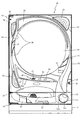
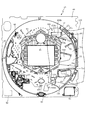
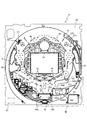
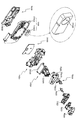
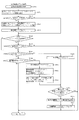
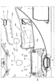
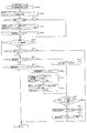
以下、本発明の実施形態について、添付図面を参照して説明する。まず、図1〜図58を参照し、第1実施形態として、本発明をパチンコ遊技機(以下、単に「パチンコ機」という)10に適用した場合の一実施形態について説明する。図1は、第1実施形態におけるパチンコ機10の正面図であり、図2はパチンコ機10の遊技盤13の正面図であり、図3はパチンコ機10の背面図である。
<First Embodiment>
Embodiments of the present invention will be described below with reference to the accompanying drawings. First, with reference to FIGS. 1 to 58, as a first embodiment, an embodiment in which the present invention is applied to a pachinko gaming machine (hereinafter simply referred to as “pachinko machine”) 10 will be described. 1 is a front view of a
パチンコ機10は、図1に示すように、略矩形状に組み合わせた木枠により外殻が形成される外枠11と、その外枠11と略同一の外形形状に形成され外枠11に対して開閉可能に支持された内枠12とを備えている。外枠11には、内枠12を支持するために正面視(図1参照)左側の上下2カ所に金属製のヒンジ18が取り付けられ、そのヒンジ18が設けられた側を開閉の軸として内枠12が正面手前側へ開閉可能に支持されている。
As shown in FIG. 1, the
内枠12には、多数の釘や、始動口630、631、640、67等を有する遊技盤13(図2参照)が裏面側から着脱可能に装着される。この遊技盤13の前面を球が流下することにより弾球遊技が行われる。なお、内枠12には、球を遊技盤13の前面領域に発射する球発射ユニット112a(図6参照)やその球発射ユニット112aから発射された球を遊技盤13の前面領域まで誘導する発射レール(図示せず)等が取り付けられている。
A game board 13 (see FIG. 2) having a large number of nails and start
内枠12の前面側には、その前面上側を覆う前面枠14と、その下側を覆う下皿ユニット15とが設けられている。前面枠14及び下皿ユニット15を支持するために正面視(図1参照)左側の上下2カ所に金属製のヒンジ19が取り付けられ、そのヒンジ19が設けられた側を開閉の軸として前面枠14及び下皿ユニット15が正面手前側へ開閉可能に支持されている。なお、内枠12の施錠と前面枠14の施錠とは、シリンダ錠20の鍵穴21に専用の鍵を差し込んで所定の操作を行うことでそれぞれ解除される。
On the front side of the
前面枠14は、装飾用の樹脂部品や電気部品等を組み付けたものであり、その略中央部には略楕円形状に開口形成された窓部14cが設けられている。前面枠14の裏面側には2枚の板ガラスを有するガラスユニット16が配設され、そのガラスユニット16を介して遊技盤13の前面がパチンコ機10の正面側に視認可能となっている。
The
前面枠14には、球を貯留する上皿17が前方へ張り出して上面を開放した略箱状に形成されており、この上皿17に賞球や貸出球などが排出される。上皿17の底面は正面視(図1参照)右側に下降傾斜して形成され、その傾斜により上皿17に投入された球が球発射ユニット112aへと案内される。また、上皿17の上面には、枠ボタン22(図11(a))と選択スイッチ600(図11(b)参照)が設けられている。この枠ボタン22は、例えば、後述する第3図柄表示装置81(図2)で表示される演出や背景などを可変させる場合などに、遊技者により操作される。
On the
選択スイッチ600は、図11(b)に示すように、演出等の選択を決定する決定スイッチ(a)、左方向の選択を指示するための左スイッチ600b、上方向の選択を指示するための上スイッチ600c、右方向の選択を指示するための右スイッチ600d下方向の選択を指示するための下スイッチ600eで構成されている。
As shown in FIG. 11 (b), the
前面枠14には、その周囲(例えばコーナー部分)に各種ランプ等の発光手段が設けられている。これら発光手段は、大当たり時や所定のリーチ時等における遊技状態の変化に応じて、点灯または点滅することにより発光態様が変更制御され、遊技中の演出効果を高める役割を果たす。窓部14cの周縁には、LED等の発光手段を内蔵した電飾部29〜33が設けられている。パチンコ機10においては、これら電飾部29〜33が大当たりランプ等の演出ランプとして機能し、大当たり時やリーチ演出時等には内蔵するLEDの点灯や点滅によって各電飾部29〜33が点灯または点滅して、大当たり中である旨、或いは大当たり一歩手前のリーチ中である旨が報知される。また、前面枠14の正面視(図1参照)左上部には、LED等の発光手段が内蔵され賞球の払い出し中とエラー発生時とを表示可能な表示ランプ34が設けられている。
The
また、右側の電飾部32下側には、前面枠14の裏面側を視認できるように裏面側より透明樹脂を取り付けて小窓35が形成され、遊技盤13前面の貼着スペースK1(図2参照)に貼付される証紙等はパチンコ機10の前面から視認可能とされている。また、パチンコ機10においては、より煌びやかさを醸し出すために、電飾部29〜33の周りの領域にクロムメッキを施したABS樹脂製のメッキ部材36が取り付けられている。
In addition, a
窓部14cの下方には、貸球操作部40が配設されている。貸球操作部40には、度数表示部41と、球貸しボタン42と、返却ボタン43とが設けられている。パチンコ機10の側方に配置されるカードユニット(球貸しユニット)(図示せず)に紙幣やカード等を投入した状態で貸球操作部40が操作されると、その操作に応じて球の貸出が行われる。具体的には、度数表示部41はカード等の残額情報が表示される領域であり、内蔵されたLEDが点灯して残額情報として残額が数字で表示される。球貸しボタン42は、カード等(記録媒体)に記録された情報に基づいて貸出球を得るために操作されるものであり、カード等に残額が存在する限りにおいて貸出球が上皿17に供給される。返却ボタン43は、カードユニットに挿入されたカード等の返却を求める際に操作される。なお、カードユニットを介さずに球貸し装置等から上皿17に球が直接貸し出されるパチンコ機、いわゆる現金機では貸球操作部40が不要となるが、この場合には、貸球操作部40の設置部分に飾りシール等を付加して部品構成は共通のものとしても良い。カードユニットを用いたパチンコ機と現金機との共通化を図ることができる。
A ball
上皿17の下側に位置する下皿ユニット15には、その中央部に上皿17に貯留しきれなかった球を貯留するための下皿50が上面を開放した略箱状に形成されている。下皿50の右側には、球を遊技盤13の前面へ打ち込むために遊技者によって操作される操作ハンドル51が配設され、かかる操作ハンドル51の内部には球発射ユニット112aの駆動を許可するためのタッチセンサ51aと、押下操作している期間中には球の発射を停止する押しボタン式の打ち止めスイッチ51bと、操作ハンドル51の回動操作量を電気抵抗の変化により検出する可変抵抗器(図示せず)とが内蔵されている。操作ハンドル51が遊技者によって右回りに回転操作されると、タッチセンサ51aがオンされると共に可変抵抗器の抵抗値が操作量に対応して変化し、操作ハンドル51の回動操作量に応じて変化する可変抵抗器の抵抗値に対応した強さで球が発射され、これにより遊技者の操作に対応した飛び量で遊技盤13の前面へ球が打ち込まれる。また、操作ハンドル51が遊技者により操作されていない状態においては、タッチセンサ51aおよび打ち止めスイッチ51bがオフとなっている。
In the
なお、本実施形態では、上記した構成としたが、それに限らず、主制御装置110や他の制御装置が球発射ユニット112aにより発射された遊技球を検出する構成や、球発射ユニット112aのソレノイドが遊技球を発射したことを検出するように構成してもよい。また、検出した遊技球の数をカウントして、RAMクリア等の処理が実行されるまで記憶するように構成してもよい。
In the present embodiment, the above-described configuration is used. However, the configuration is not limited thereto, and a configuration in which the
下皿50の正面下方部には、下皿50に貯留された球を下方へ排出する際に操作するための球抜きレバー52が設けられている。この球抜きレバー52は、常時、右方向に付勢されており、その付勢に抗して左方向へスライドさせることにより、下皿50の底面に形成された底面口が開口して、その底面口から球が自然落下して排出される。この球抜きレバー52の操作は、通常、下皿50の下方に下皿50から排出された球を受け取る箱(一般に「ドル箱」と称される)を置いた状態で行われる。下皿50の右方には、上述したように操作ハンドル51が配設され、下皿50の左方には灰皿53が取り付けられている。
In the lower part of the front of the
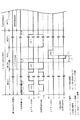
図2に示すように、遊技盤13は、正面視略正方形状に切削加工した木製のベース板60に、球案内用の多数の釘や風車およびレール61,62、第1始動口63a、第2始動口63b、第1可変入賞装置65、可変表示装置ユニット80等を組み付けて構成され、その周縁部が内枠12の裏面側に取り付けられる。第1始動口630、右第1始動口631、第2始動口640、第1可変入賞装置65、可変表示装置ユニット80は、ルータ加工によってベース板60に形成された貫通穴に配設され、遊技盤13の前面側から木ネジ等により固定されている。また、遊技盤13の前面中央部分は、前面枠14の窓部14c(図1参照)を通じて内枠12の前面側から視認することができる。以下に、主に図2を参照して、遊技盤13の構成について説明する。
As shown in FIG. 2, the
遊技盤13の前面には、帯状の金属板を略円弧状に屈曲加工して形成した外レール62が植立され、その外レール62の内側位置には外レール62と同様に帯状の金属板で形成した円弧状の内レール61が植立される。この内レール61と外レール62とにより遊技盤13の前面外周が囲まれ、遊技盤13とガラスユニット16(図1参照)とにより前後が囲まれることにより、遊技盤13の前面には、球の挙動により遊技が行われる遊技領域が形成される。遊技領域は、遊技盤13の前面であって2本のレール61,62と円弧部材とにより区画して形成される略円形状の領域(始動口等が配設され、発射された球が流下する領域)である。また、遊技領域は、戻り球防止部材68を通過した遊技球がアウト口66や入賞口を通過するまでに流下する領域はすべて含まれる。
An
2本のレール61,62は、球発射ユニット112a(図6参照)から発射された球を遊技盤13上部へ案内するために設けられたものである。内レール61の先端部分(図2の左上部)には戻り球防止部材68が取り付けられ、一旦、遊技盤13の上部へ案内された球が再度球案内通路内に戻ってしまうといった事態が防止される。外レール62の先端部(図2の右上部)には、球の最大飛翔部分に対応する位置に返しゴム69が取り付けられ、所定以上の勢いで発射された球は、返しゴム69に当たって、勢いが減衰されつつ中央部側へ跳ね返される。また、内レール61の右下側の先端部と外レール62の右上側の先端部との間には、レール間を繋ぐ円弧を内面側に設けて形成された樹脂製の円弧部材がベース板60に打ち込んで固定されている。
The two
遊技盤13の右側には、第1普通図柄始動口67aとその第1普通図柄始動口67aの下方に第2普通図柄始動口67bとが設けられている。第1普通図柄始動口67aと第2普通図柄始動口67bとは、同一の形状で構成されており、ゲート型で遊技球の通過を検出することができるセンサを有した始動口で構成されている。第1普通図柄始動口67aまたは第2普通図柄始動口67bを遊技球が通過した場合に、普通図柄(第2図柄)の抽選が行われる。第1普通図柄始動口67aまたは第2普通図柄始動口67bへ遊技球が通過したことに対して行われる抽選では、普通図柄の当たりか否かの当否判定が行われる。
On the right side of the
普通図柄(第2図柄)の抽選が行われると、後述する、可変表示装置ユニット80に設けられた第2図柄表示装置83において普通図柄の変動表示が開始されて、「○」と「×」の図柄が交互に所定時間(例えば、20秒)点灯した後に、抽選結果を示す普通図柄(本実施形態では「○」もしくは「×」の図柄)が停止表示(点灯表示)される。第2図柄表示装置83において変動表示が行われている間に第1普通図柄始動口67または第2普通図柄始動口67bに球が通過すると、その通過回数は、第1普通図柄始動口67aと第2普通図柄始動口67bとで合わせて最大4回まで保留される。その保留球数は第1図柄表示装置37により表示される。第2図柄表示装置83において変動表示が終了した場合に、普通図柄始動口67(第1普通図柄始動口67aまたは第2普通図柄始動口67b)についての保留球数が残っていれば、次の普通図柄の抽選が行われると共に、その抽選に応じた変動表示が開始される。
When the normal symbol (the second symbol) is drawn, the normal symbol variation display is started on the second
普通図柄の当たりと判定された場合には、第2図柄表示装置83に普通図柄の抽選が当たりであったことを示す図柄である「○」が点灯表示される。当たりである図柄が表示されると、第1普通電動役物632が作動する。第1普通電動役物632は、左誘導部材632aと右誘導部材632bとを有しており、その左誘導部材632aと右誘導部材632bとを左右に遊技球1球が通過可能な間隔を空けて通常時は上方に起立した状態で維持されている。左誘導部材632aと右誘導部材632bとが略垂直に起立した状態から所定角度(本実施形態では、左誘導部材632aが反時計回りに40度、右誘導部材632bが時計回りに40度)回動し(即ち、開状態へと可変され)、遊技球を左誘導部材632aと右誘導部材とが第2始動口640へ誘導することにより、第2始動口640内に遊技球が入球し易い状態(特別状態)になる。一方、普通図柄の外れと判定された場合には、第2図柄表示装置83に普通図柄の抽選が外れであったことを示す図柄である「×」が点灯表示される。このときには、第1普通電動役物632は作動されず、次の普通図柄(第2図柄)の変動が実行される。
If it is determined that the normal symbol is won, the second
遊技領域の正面視右側上部(図2の右側上部)には、発光手段である複数の発光ダイオード(以下、「LED」と略す)37aと7セグメント表示器37bとが設けられた第1図柄表示装置37が配設されている。第1図柄表示装置37は、後述する主制御装置110で行われる各制御に応じた表示がなされるものであり、主にパチンコ機10の遊技状態の表示が行われる。複数のLED37aは、第1始動口630、右始動口631、第2始動口640、第1普通図柄始動口(スルーゲート)67a、第2普通図柄始動口(スルーゲート)67bに入賞された球のうち変動表示が未実行である球(保留球)の数である保留球数を点灯状態により示すものである。また、大当たり中のラウンド数やエラー表示もそれに対応する点灯状態により示される。
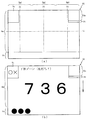
A first symbol display in which a plurality of light emitting diodes (hereinafter abbreviated as “LED”) 37a and a 7-
7セグメント表示器37bは、左右に2つの7セグメントLEDで構成されている。左側の7セグメントLEDは、第1始動口630または右始動口631への入賞に基づく抽選(以下、第1抽選遊技という)の判定(抽選)結果を示す第1特別図柄が変動表示(動的表示)される。具体的には、第1始動口630または右第1始動口631への入賞に基づいて決定された、変動時間(動的表示時間)が経過するまで変動表示(本実施形態では、7セグメントの中央のセグメントが点滅表示)した後に、判定結果を示す図柄で停止表示される。判定結果が外れの場合には中央の1セグメントが点灯表示する外れを示す図柄「−」が表示される。一方、判定結果が当たりである場合には、当たりに対応した図柄「3」、「7」などの外れを示す図柄とは異なる図柄が表示される。
The 7-
右側の7セグメントLEDには、第2始動口640への入賞に基づく抽選(第2抽選遊技)の判定(抽選)結果を示す第2特別図柄が(動的表示)される。具体的には、第2始動口640への入賞に基づいて決定された変動時間が経過するまで表示されるものであり、第1抽選遊技と同様に構成されている。なお、LED37aは、それぞれのLEDの発光色(例えば、赤、緑、青)が異なるよう構成され、その発光色の組み合わせにより、少ないLEDでパチンコ機10の各種遊技状態を示唆することができる。
On the right 7-segment LED, a second special symbol indicating the result of lottery (second lottery game) determination (lottery) based on winning at the
なお、第1抽選遊技の判定(抽選)結果を示す第1特別図柄と、第2抽選遊技の判定(抽選)結果を示す第2特別図柄とは、後述する第3図柄表示装置81(図2参照)にも表示される。これにより、第3図柄表示装置81では7セグメント表示器37bに比べて多様な変動表示を行うことができるので、遊技者の興趣を向上させることができる。
The first special symbol indicating the determination result (lottery) of the first lottery game and the second special symbol indicating the determination result (lottery) of the second lottery game are the third symbol display device 81 (FIG. 2) described later. (See). Thereby, since the 3rd
また、パチンコ機10における変動パターン(変動態様または動的表示態様)は、後述するが、変動態様毎に変動時間が設定されており、時間情報に関する動的表示態様に該当する。さらには、変動パターンは、リーチとなる変動パターンと非リーチとなる変動パターンとで、変動時間の比較的長い長時間変動パターンと比較的変動時間の短い短時間変動パターンとに分けることもできる。このように、大まかに、時間の一定基準(ここでは、リーチ、非リーチ、または、基準時間(例えば、10秒より長いか否か))で仕分けた場合に対しても、時間情報に関する動的表示態様に該当する。
Moreover, although the fluctuation pattern (variation mode or dynamic display mode) in the
また、後述するが、変動開始時間となるまでの時間情報については、正確な変動開始となる時間も該当するし、上記した、大まかな変動パターンの時間情報(例えば、長時間変動パターンであるか否か等)に基づいて決定される時間情報(例えば、変動開始までに行われる長時間変動パターンの回数等)についての情報も該当する。 As will be described later, the time information until the fluctuation start time corresponds to the time when the fluctuation starts accurately, and the time information of the rough fluctuation pattern described above (for example, whether it is a long-time fluctuation pattern). Information on time information (for example, the number of long-time variation patterns performed before the start of variation) is also applicable.
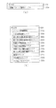
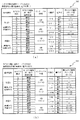
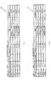
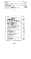
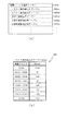
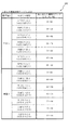
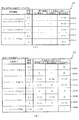
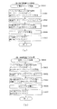
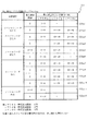
尚、本パチンコ機10では、第1始動口630、右第1始動口631、第2始動口640への入賞に対して行われる抽選(第1抽選遊技、第2抽選遊技)において、大当たりか否かの当否判定(大当たり抽選)を行うと共に、大当たり種別の判定も行う。ここで判定される大当たり種別としては、第1特別図柄(特図1)の大当たり種別として、大当たりA(15R大当たり確変大当たり)、大当たりB(15R通常大当たり)、大当たりE(15R通常大当たり(電サポ有り))の3種類が設定されている(図16(a)〜(c)参照)。ここで、大当たりEの電サポ有りとは、第1普通電動役物632が特別状態(開状態)に設定され易く設定される当たりであることを示している。大当たりEでは、15ラウンドの大当たり遊技後、第1抽選遊技と第2抽選遊技の回数が合わせて100回となるまで電サポ状態が設定される。
In the
第2特別図柄(特図2)の大当たり種別として、大当たりC(15R確変大当たり(電サポ有り))、大当たりD(15R確変大当たり(電サポ無し))の2種類が設定されている(図16(a)〜(c)参照)。 As the jackpot type of the second special symbol (special chart 2), two types of jackpot C (15R probability variation jackpot (with electric support)) and jackpot D (15R probability variation jackpot (without electric support)) are set (FIG. 16). (See (a) to (c)).
ここで、本実施形態の構成では、大当たり遊技中に開放状態に作動される入賞装置として第1可変入賞装置65が配置されている。第1可変入賞装置65は、大当たりA〜Eについて、第1特定入賞口65aが15回所定期間または所定数(本実施形態では10球)の遊技球が入球するまで開放されるように作動される。
Here, in the configuration of the present embodiment, the first variable winning
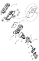
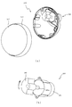
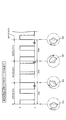
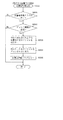
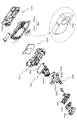
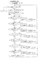
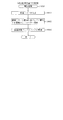
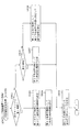
図4〜図6を参照して、この第1可変入賞装置65の構成について説明する。図4は、この第1可変入賞装置65の分解斜視図である。第1可変入賞装置65は、図4に示すように、遊技盤13の前面側に突出して配置される開口部形成部材65b、その開口部形成部材65bの背面側に組み合わされて、第1可変入賞装置65を遊技盤13にビス留めするためのベース部材65cと、そのベース部材65cの背面側に配置されてベース部材65cの背面側よりパチンコ機10の前面側に対してLEDを点灯させるためのLEDが複数配置されたLED基板65dと、そのLED基板65dをベース部材65cと狭持する裏カバー体65eと、開口部形成部材65bに形成されている第1特定入賞口65aを開閉するための開閉扉65f1を有した開閉ユニット65fと、裏カバー体65eの背面側に組み合わされて流路を形成する流路カバー体65gと、裏カバー体65eと流路カバー体65gとで形成された流路に突出して遊技球の流路を切り替える切替部材65hと、その切替部材65hと係止されるリンク部材65iと、流路カバー体65gの背面側に配置される背面カバー体65jと、その背面カバー体65jの背面側に固定されて、リンク部材65iを作動させる流路ソレノイド65kと、その流路ソレノイド65kを背面側から覆って背面カバー体65jにビスにより固定するための固定用カバー体65mとで構成されている。
The configuration of the first variable winning
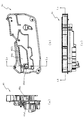
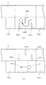
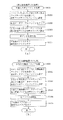
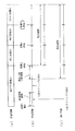
図5は、第1可変入賞装置65の断面図である。図5(c)は第1可変入賞装置65の上面図であり、図5(b)は、第1可変入賞装置65のLb−Lb断面図である。図5(b)に示すように、第1可変入賞装置65には、遊技球が入球可能な開口部である第1特定入賞口65aが形成されている。第1特定入賞口65aは、パチンコ機10の上方を略長方形状の開口が形成されており、その開口を通過した遊技球が図5(b)の左方向に誘導されるように左下方に傾斜した底面が形成されている。底面の左端部には、遊技球の入賞を検知するための磁気センサで構成された検出口65a1が配置されている。この検出口65a1を通過した遊技球は、図6(b)で示す裏カバー体65eの背面側に形成された振り分け流路へと誘導される。
FIG. 5 is a cross-sectional view of the first variable winning
なお、図5(b)に示すように第1特定入賞口65aの開口は、遊技盤13側より出没可能なシャッター機構で構成された開閉扉65f1により遊技球が入球可能な開放状態と入球不可能(入球困難)な閉鎖状態とに可変される。閉鎖状態では、開口が完全に開閉扉65f1によって覆われ、開閉扉の上部を遊技球が転動可能に構成される。また、開放状態では、開閉扉65f1は、ベース部材65cの内側(遊技盤13の内部)に退避されることにより第1特定入賞口65a内から退避されるように構成されている。
As shown in FIG. 5 (b), the opening of the first
このように構成することで、第1可変入賞装置65の開口が閉鎖されている場合には、遊技球が第1可変入賞装置65の上面を転動して、右第1始動口631側へと誘導されるように構成されている。よって、時短遊技中(確変遊技中含む)にも、右打ちした状態のまま、第2始動口640へと遊技球を入球させることが可能となり、大当たり遊技後に直ちに左打ちへと遊技方法を変更させる手間を軽減できる。従って、より楽に遊技を行うことができる。
With this configuration, when the opening of the first variable winning
また、開放状態においては、遊技球が流下する方向と直交する面を第1可変入賞装置65の開口として構成できるので、より多くの遊技球が効率よく第1特定入賞口65a内に入賞できる。よって、大当たり遊技に要する時間を短くすることができ、遊技の効率化をはかることができる。
Further, in the open state, the surface orthogonal to the direction in which the game ball flows down can be configured as the opening of the first variable winning
図5(a)は、図5(b)に示すLa−La断面図である。図5(a)に示すように検出口65a1を有する検出スイッチ65c1は、裏カバー体65eの振り分け流路側へと検出口65a1が傾くようにベース部材65cに固定されている。
Fig.5 (a) is La-La sectional drawing shown in FIG.5 (b). As shown in FIG. 5A, the detection switch 65c1 having the detection port 65a1 is fixed to the
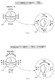
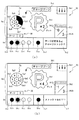
図6を参照して、裏カバー体65eの振り分け流路に誘導された遊技球が後述する通常排出口65e1と特別排出口65e2とに振り分けられる構成について説明する。
With reference to FIG. 6, the structure by which the game ball induced | guided | derived to the distribution flow path of the
図6(a)は、遊技球が特別排出口65e2に振り分けられるように切替部材65hが作動された状態を示す裏カバー体65eの背面図である。図6(a)に示すように、切替部材65hは、リンク部材65iの突部が挿入される係止穴65h1と遊技球を誘導する誘導片65h2とを有しており、流路カバー体65gに背面側より回動可能に軸支されている。ここで、流路カバー体65gには、この誘導片65h2を挿通することが可能な開口部が設けられており、流路カバー体65gの背面側より振り分け流路内に誘導片65h2を回動可能に配置することが可能に構成されている。
FIG. 6A is a rear view of the
図6(a)に示すように、検出口65a1より振り分け流路内に誘導された遊技球は、左斜め下方に配置された誘導片65h2の上面に誘導されて特別排出口65e2に誘導される。特別排出口65e2を通過した遊技球は特別排出口65e2に設けられた遊技球の通過を検出可能な磁気センサで構成された確変スイッチ65e3により検出されてアウト球としてパチンコ機10外へ排出される。
As shown in FIG. 6A, the game ball guided into the distribution channel from the detection port 65a1 is guided to the upper surface of the guide piece 65h2 arranged diagonally to the left and is guided to the special discharge port 65e2. . The game ball that has passed through the special discharge port 65e2 is detected by a probability change switch 65e3 configured by a magnetic sensor that can detect the passage of the game ball provided in the special discharge port 65e2, and is discharged out of the
ここで、詳細については後述するが、本実施形態におけるパチンコ機10では、大当たり遊技中に上記した確変スイッチ65e3を遊技球が通過することにより、大当たり遊技後の遊技状態が高確率遊技状態(確変遊技状態)に設定される。即ち、確変スイッチ65e3は、確変遊技状態を付与するための入賞口として構成されている。また、切替部材65hは、大当たり後の遊技状態を低確率遊技状態(通常遊技状態ST1)か確変遊技状態かに振り分けるための構成となる。
Here, although details will be described later, in the
このように、大当たり遊技中に第1特定入賞口65aに入賞した遊技球の流下ルートにより大当たり遊技後に設定される遊技状態が可変されるので、大当たり遊技中にも遊技者の興趣を向上させることができる。なお、第1可変入賞装置65の開口から特別排出口65e2の入り口(切替部材65hの誘導片65h2により閉鎖さる開口面)を通過するのに必要な時間は、最短でも1秒で構成されている。切替部材65hの作動は、大当たり種別により作動タイミングと作動時間が設定されている。本実施形態では、大当たりA、大当たりC、大当たりDに当選した場合には、14ラウンド目の開始における第1可変入賞装置65の開放タイミングに合わせて切替部材65hが5秒間作動されるように構成されている。また、大当たりB、大当たりEに当選した場合には、14ラウンド目の開始における第1可変入賞装置65の開放タイミングに合わせて切替部材65hが0.5秒間作動されるように構成されている。
In this way, since the gaming state set after the jackpot game is changed by the flow route of the game ball that won the first specific winning
よって、大当たりAでは、第1可変入賞装置65に入賞した遊技球が確変スイッチ65e3を通過することが可能に構成されているが、大当たりBでは、確変スイッチ65e3を通過することが不可能に構成されている。よって、大当たり種別により確変付与割合を制御することができ、過剰に有利不利が発生してしまわないように構成できる。
Therefore, in the jackpot A, it is configured that the game ball that has won the first variable winning
図6(b)を参照して、通常排出口65e1に遊技球が誘導される場合について説明する。図6(b)は、流路ソレノイド65kが非作動であり、特別排出口65e2の入り口の開口面を切替部材65hの誘導片65h2が塞いでいる状態を示す図である。
With reference to FIG.6 (b), the case where a game ball is guide | induced to the normal discharge port 65e1 is demonstrated. FIG. 6B is a diagram illustrating a state in which the
検出口65a1より振り分け流路に誘導された遊技球は、切替部材65hの誘導片65h2の上面に誘導されて通常排出口65e1に誘導される。この通常排出口65e1の端部には遊技球の通過を検出可能な磁気センサで構成された球排出口スイッチ65e4が設けられている。これにより、第1可変入賞装置65内に入球した遊技球が全て排出されたかを球排出口スイッチ65e4と確変スイッチ65e3との合計により判別できる。よって、14ラウンド前に入賞した遊技球が排出されていない状態で14ラウンド目に入賞して、大当たりBであっても確変スイッチ65e3に入賞する不具合を抑制できる。
The game ball guided to the distribution channel from the detection port 65a1 is guided to the upper surface of the guide piece 65h2 of the switching
このように、第1可変入賞装置65内に第1特定入賞口65aに入賞した遊技球が検出スイッチ65c1により検出され、それに基づいて、遊技者に特典として賞球(本実施形態では1球入賞に対して15個の賞球)を払い出すことができる。また、その検出された後の遊技球を利用して、確変スイッチ65e3に通過するか否かを振り分け可能に構成することで、確変遊技状態を付与するか否かの抽選も実行することができる。よって、確変遊技状態を付与するための専用の入賞口を第1可変入賞装置65とは別に設ける必要がなく、遊技盤13のスペースを有効に利用することができる。
In this way, the game ball that has won the first
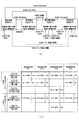
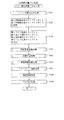
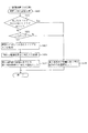
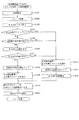
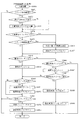
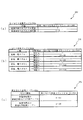
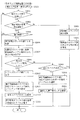
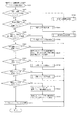
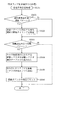
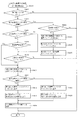
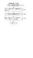
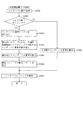
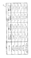
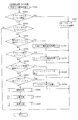
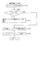
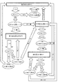
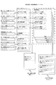
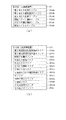
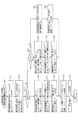
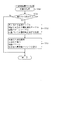
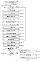
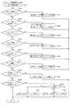
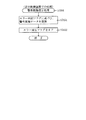
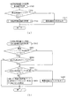
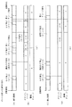
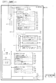
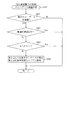
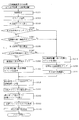
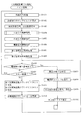
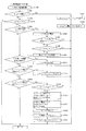
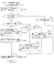
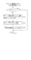
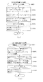
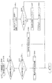
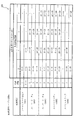
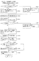
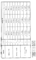
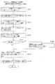
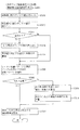
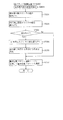
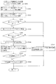
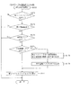
次に、図7を参照して、本実施形態における各種遊技状態について説明する。図7(a)は、各種遊技状態が設定される流れを示した図である。図7(b)は、各種遊技状態において、特別図柄毎に発生する大当たり種別と、その大当たりが発生した後に移行する遊技状態を示した図である。 Next, with reference to FIG. 7, various gaming states in the present embodiment will be described. FIG. 7A is a diagram illustrating a flow in which various game states are set. FIG. 7B is a diagram showing a jackpot type that occurs for each special symbol and a gaming state that shifts after the jackpot occurs in various gaming states.
本実施形態では、図7(a)に示す通り、遊技状態として次の4つの遊技状態が設定されるように構成されている。1つ目は、特別図柄の大当たり確率が低確率(通常)であり、電サポ無(第1普通電動役物632が特別状態(開状態)となりにくい)遊技状態である通常遊技状態ST1。2つ目は、通常遊技状態ST1と同じく特別図柄の大当たり確率が低確率(通常)であるものの、電サポ有(第1普通電動役物632が特別状態(開状態)となり易い)遊技状態である時短遊技状態ST1h。3つ目は、特別図柄の大当たり確率が高確率であり、電サポ無(第1普通電動役物632が特別状態(開状態)となりにくい)遊技状態である確変電サポ無遊技状態(所謂、潜伏確変遊技状態)ST2。4つ目は、特別図柄の大当たり確率が高確率であり、尚且つ、電サポ有(第1普通電動役物632が特別状態(開状態)となり易い)遊技状態である確変電サポ有遊技状態(所謂、確変遊技状態)ST3。
In the present embodiment, as shown in FIG. 7A, the following four gaming states are set as the gaming state. The first is a normal gaming state ST1 in which the jackpot probability of a special symbol is low (normal) and there is no electric support (the first ordinary
本実施形態では、第1特別図柄の変動と第2特別図柄の変動とを同時に実行することが可能に構成されている。しかし、各遊技状態においては、どちらか一方の特別図柄の変動が実質的に行われる(実質変動対象であるともいう)ように構成されている。具体的には、実質変動対象である特別図柄の変動時間に比べて、実質変動対象でない特別図柄の変動時間が長くなるように構成されている。また、実質変動対象でない特別図柄の抽選を行うための始動口へ遊技球が入球し難い遊技状態、または、実質変動対象である特別図柄の抽選を行うための始動口へ遊技球が入球し易い遊技状態となるように構成している。これにより、実質変動対象でない特別図柄の大当たりを実質的に発生させず(発生し難くし)、実質変動対象である特別図柄の大当たりを実質的に発生させる(発生し易くする)ことができる。 In the present embodiment, the first special symbol variation and the second special symbol variation can be executed simultaneously. However, each game state is configured such that one of the special symbols is substantially changed (also referred to as a subject of substantial change). Specifically, it is configured such that the variation time of the special symbol that is not the subject of substantial variation is longer than the variation time of the special symbol that is the subject of substantial variation. In addition, it is difficult for a game ball to enter the starting port for drawing a special symbol that is not subject to substantial variation, or a gaming ball enters the starting port for performing a lottery of a special symbol that is subject to substantial variation. It is configured to be in a gaming state that is easy to play. As a result, it is possible to substantially generate the jackpot of the special symbol that is not subject to substantial variation (to make it difficult to generate) and to substantially generate the jackpot of the special symbol that is subject to substantial variation (to make it easier to generate).
なお、いずれか一方の特別図柄を実質変動対象とする方法は、上述した方法に限られるものではない。例えば、第1特別図柄の抽選契機となる始動口と第2特別図柄の抽選契機となる始動口とにそれぞれ普通電動役物を設ける。そして、各遊技状態において、実質変動対象とする特別図柄に対応する始動口の普通電動役物のみを可動する(または、し易い)ようにすることが考えられる。これにより、実質変動対象である特別図柄に対応する始動口へは遊技球が入球し、実質変動対象でない特別図柄に対応する始動口へは遊技球が入球しない(入球し難い)ようにできる。この場合に、各始動口に設けられる普通電動役物を可動するための抽選を別々に行うようにしてもよい。例えば、一方の普通電動役物を可動するための抽選を第1普通図柄始動口への入球(通過)に基づいて行い(第1普通図柄の抽選という)、他方の普通電動役物を可動するための抽選を第2普通図柄始動口への入球(通過)で行う(第2普通図柄の抽選という)ようにしてもよい。さらに、第1普通図柄の抽選と第2普通図柄の抽選とは同時に実行可能としてもよく、本実施形態における特別図柄の抽選と同様に、一方の普通図柄の抽選が大当たりとなった場合には、他方の普通図柄の抽選が外れとなるようにしてもよい。これにより、遊技状態のバリエーションを増やすことができ、遊技者の興趣を向上できる。 In addition, the method which makes any one special symbol the object of substantial variation is not restricted to the method mentioned above. For example, a normal electric accessory is provided at each of a start opening serving as a lottery opportunity for the first special symbol and a start opening serving as a lottery opportunity for the second special symbol. Then, in each gaming state, it is conceivable to move (or easily) only the ordinary electric accessory at the start port corresponding to the special symbol to be substantially changed. As a result, the game ball enters the starting port corresponding to the special symbol that is the subject of substantial variation, and the gaming ball does not enter the starting port corresponding to the special symbol that is not the subject of substantial variation (it is difficult to enter). Can be. In this case, a lottery for moving the ordinary electric accessory provided at each start port may be performed separately. For example, a lottery for moving one ordinary electric accessory is performed based on a ball entering (passing) the first ordinary symbol start opening (referred to as a first ordinary symbol lottery), and the other ordinary electric accessory is movable. The lottery may be performed by entering (passing) the second normal symbol start opening (referred to as a second normal symbol lottery). Further, the lottery of the first normal symbol and the lottery of the second normal symbol may be executable simultaneously, and when the lottery of one normal symbol becomes a big hit, as in the case of the special symbol lottery in the present embodiment. The other normal symbol lottery may be excluded. Thereby, the variation of a game state can be increased and the interest of a player can be improved.
本実施形態では、第1特別図柄に基づく大当たりと、第2特別図柄に基づく大当たりとでは、確変スイッチ65e3を遊技球が通過可能な大当たりが選択される確率が異なる。即ち、高確率遊技状態(潜伏確変遊技状態ST2または確変遊技状態ST3)に移行(ループ)可能な確率が異なる。具体的には図16を参照して後述するが、第1特別図柄に基づく大当たりは高確率遊技状態(潜伏確変遊技状態ST2または確変遊技状態ST3)に移行(ループ)可能となる確率が低い(34%)、即ち、低確率状態(通常遊技状態ST1または時短遊技状態ST1h)に移行(転落)する確率が高い(66%)。一方、第2特別図柄に基づく大当たりは高確率遊技状態(潜伏確変遊技状態ST2または確変遊技状態ST3)に移行(ループ)可能となる確率が高い(100%)。なお、以下、各種遊技状態が設定される流れを説明するに当たり、便宜上、高確率遊技状態への移行可能(確変スイッチ65e3を遊技球が通過可能な)となる大当たりが選択された(発生した)場合には、高確率遊技状態へ移行する(確変スイッチ65e3を遊技球が通過する)ものとして説明する。 In the present embodiment, the probability that the jackpot that allows the game ball to pass through the probability variation switch 65e3 is different between the jackpot based on the first special symbol and the jackpot based on the second special symbol. That is, the probabilities of being able to shift (loop) to the high-probability gaming state (latent probability variation gaming state ST2 or probability variation gaming state ST3) differ. Specifically, as will be described later with reference to FIG. 16, the jackpot based on the first special symbol has a low probability of being able to shift (loop) to a high-probability gaming state (latent probability variation gaming state ST2 or probability variation gaming state ST3) ( 34%), that is, there is a high probability (66%) of transition (falling) to a low probability state (normal gaming state ST1 or short-time gaming state ST1h). On the other hand, the jackpot based on the second special symbol has a high probability (100%) of being able to shift (loop) to a high probability gaming state (latent probability variation gaming state ST2 or probability variation gaming state ST3). In the following, for explaining the flow of setting various gaming states, for the sake of convenience, a jackpot that allows transition to a high-probability gaming state (a gaming ball can pass through the probability variation switch 65e3) has been selected (occurred). In this case, description will be made on the assumption that the game state shifts to the high probability gaming state (the game ball passes through the probability change switch 65e3).
各遊技状態において、実質変動対象となる特別図柄を設定することにより、高確率遊技状態へ移行(ループ)し易いか、低確率状態へ移行(転落)しやすいかを調整(設定)できる。これにより、各遊技状態では、抽選結果が大当たりとなる確率として2種類(高確率、低確率)の状態に加え、大当たり後に高確率遊技状態に移行(ループ)する割合(確率)として2種類(高確率遊技状態への移行が高確率、低確率)の状態を設定できる。よって、遊技状態のバリエーションを増やすことができ、遊技者の興趣を向上できる。 In each gaming state, it is possible to adjust (set) whether a transition to a high probability gaming state (loop) or a transition to a low probability state (falling) is easy by setting a special symbol that is a substantial variation target. As a result, in each gaming state, in addition to two types (high probability, low probability) of probability that the lottery result will be a jackpot, two types (probability) of transition (loop) to a high probability gaming state after the jackpot (probability) It is possible to set a state of high probability and low probability of transition to a high probability gaming state. Therefore, the variation of a game state can be increased and the interest of a player can be improved.
具体的には、高確率遊技状態である確変遊技状態ST3では実質変動対象を特図1に設定することで、低確率状態へ移行(転落)し易い遊技状態とし、同じく高確率遊技状態である潜伏確変遊技状態ST2では実質変動対象を特図2に設定することで、高確率遊技状態へ移行(ループ)し易い遊技状態とすることが可能となる。つまり、同じ高確率遊技状態(または低確率状態)であったとしても、実質変動対象となる特別図柄を変更することにより、大当たり遊技の終了後に移行する遊技状態の振り分けを変えることができるため、遊技状態が移行するバリエーションを増やすことができ、遊技者の興趣を向上できる。 Specifically, in the probability variation gaming state ST3 that is a high-probability gaming state, by setting the real variation target in FIG. 1, a gaming state that is likely to shift (fall) to a low-probability state, which is also a high-probability gaming state. In the latent probability changing game state ST2, by setting the substantial change target in FIG. 2, it becomes possible to make the game state easy to shift (loop) to the high probability game state. In other words, even if it is the same high-probability gaming state (or low-probability state), by changing the special symbol that is subject to substantial change, it is possible to change the distribution of the gaming state that transitions after the jackpot game, Variations in the transition of the gaming state can be increased, and the interest of the player can be improved.
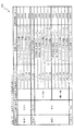
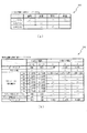
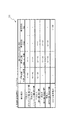
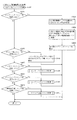
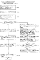
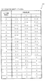
図7に戻り説明を続ける。まず、パチンコ機10が初期化された状態(RAMクリアスイッチが押下されて電源が投入された状態)では、通常遊技状態ST1が設定されている。通常遊技状態ST1では、第1特別図柄が実質変動対象となっている。即ち、高確率遊技状態へ移行する大当たりが発生する確率(確変割合)が低い(34%)遊技状態である。具体的には、第1特別図柄(特図1)の変動時間として、8000ms(8秒)から30000ms(30秒)の変動時間が選択される(図17参照)。そして、第1特別図柄の大当たりでは大当たり種別として、高確率遊技状態へ移行する大当たりA(15R確変大当たり)が34%の確率で選択され、低確率状態のままとなる大当たりB(15R通常大当たり)が66%の確率で選択される(図7(b)、図16参照)。
Returning to FIG. First, in a state where the
これに対し、通常遊技状態ST1では、実質変動対象ではない第2特別図柄(特図2)の変動時間は長く設定される。具体的には、当否判定(抽選)結果が外れである場合には、特図2の変動時間は、64800000ms(18時間)が選択される(図17参照)。よって、第2特別図柄の外れ変動が1回行われる間に、第1特別図柄では、2160〜8200回の抽選を実行することが可能となる。通常遊技状態ST1(低確率状態)での大当たり確率は、1/400であるので、通常の遊技であれば外れの第2特別図柄が1回変動終了するまでに、第1特別図柄で大当たりが発生するように構成されている。また、主に遊技店の営業時間は、朝9時から夜11までの15時間程度であるので、それよりも長い時間で設定されている。よって、通常遊技状態ST1において、第2抽選遊技が実行されても、特図2の外れ変動が営業時間内に終了しない。このように構成することで、通常遊技状態ST1において、実質変動対象である第1特別図柄(特図1)の大当たりが発生する(し易い)ようにしている。 On the other hand, in the normal gaming state ST1, the variation time of the second special symbol (special diagram 2) that is not the subject of substantial variation is set to be long. Specifically, when the result of the determination (lottery) is out of place, 64800000 ms (18 hours) is selected as the variation time in FIG. 2 (see FIG. 17). Therefore, the lottery of 2160 to 8200 times can be executed for the first special symbol while the variation of the second special symbol is performed once. Since the jackpot probability in the normal gaming state ST1 (low probability state) is 1/400, in the case of a normal game, the jackpot is hit with the first special symbol before the losing second special symbol ends once. Is configured to occur. In addition, since the business hours of the amusement shop are mainly about 15 hours from 9 am to 11 at night, they are set longer than that. Therefore, even if the second lottery game is executed in the normal game state ST1, the deviation fluctuation in FIG. 2 does not end within business hours. By configuring in this way, in the normal gaming state ST1, a big hit of the first special symbol (special diagram 1) that is the subject of substantial variation occurs (is easy to do).
仮に、第2抽選遊技が実行され、その当否判定結果が外れとならず、当たりとなった場合には、特図2の変動時間は600000ms(10分)が選択される(図17参照)。これは、具体的には後述するが、第1特別図柄と第2特別図柄とのうち、いずれか一方の特別図柄で大当たりに基づく変動が開始されると、他方の特別図柄に基づく変動は外れとなるように制御されるためである。特図2の当否判定結果が当たりの場合に、変動時間として64800000ms(18時間)が選択されると、特図2の大当たりに基づく変動が営業時間内に終了しない。よって、営業時間内に実行される特図1に基づく変動(第1抽選遊技)が全て外れとなる(大当たりとならない)ように制御されてしまうとの問題が生じる。そこで、特図2の大当たりに基づく変動は営業時間内に終了し得る時間(10分)とした。これにより、上述した問題を解消できる。 If the second lottery game is executed and the result of the determination of success / failure is not disapproved, and the winning time is a win, 60000 ms (10 minutes) is selected as the fluctuation time of FIG. 2 (see FIG. 17). This will be described in detail later, but if the variation based on the jackpot is started in one of the first special symbol and the second special symbol, the variation based on the other special symbol will be off. It is because it is controlled to become. If the determination result of special figure 2 is a win and if 64800000 ms (18 hours) is selected as the fluctuation time, the fluctuation based on the jackpot of special figure 2 does not end within business hours. Therefore, there arises a problem that control is performed such that all fluctuations (first lottery game) executed during business hours are out of place (not a big hit). Therefore, the fluctuation based on the jackpot of Special Figure 2 is defined as the time (10 minutes) that can be finished within business hours. Thereby, the problem mentioned above can be solved.
ただし、特図2の大当たりに基づく変動が短い場合(例えば、500ms(0.5秒))には、遊技者が特図2の当否判定結果を短時間で判別可能となるので、次の不正行為が実行される虞がある。例えば、第2始動口640へ遊技球を入球させ、その入球に基づく特図2の当否判定結果が外れであると判別した(特図2の変動表示が0.5秒より長く実行された)場合に、パチンコ機10をリセット(初期化)する不正行為(所謂、リセットゴト)を実行される虞がある。上述した通り、パチンコ機10のRAMクリアスイッチが押下されて電源が投入(リセット)された場合には、通常遊技状態ST1が設定され、各特別図柄の変動も初期化される(即ち、変動停止される)。よって、上記不正行為(リセットゴト)を繰り返すことで、実質変動対象でない特図2に基づく大当たりを発生させることができてしまう。そこで、本実施形態では、特図2の大当たりに基づく変動を10分とすることで、遊技者が特図2の当否判定(抽選)結果を短時間で判別可能できないようにしている。これにより、上記不正行為(リセットゴト)を実行するには最低でも10分の期間が必要となるので、上記不正行為(リセットゴト)の実行可能頻度を下げることができる。その結果、上記不正行為(リセットゴト)によって、不正に特図2の大当たりを発生させることを困難にできる。
However, when the fluctuation based on the jackpot of the special figure 2 is short (for example, 500 ms (0.5 seconds)), the player can determine the result of the special figure 2 for a short time. There is a risk of the action being performed. For example, a game ball is made to enter the
なお、特図2の変動時間は上述したものに限られず、適宜変更しても良い。例えば、意図して遊技球を発射(例えば右打ち遊技)しなければ第2抽選遊技を実行できない遊技機において、通常遊技状態ST1で右打ち遊技を行う(第2抽選遊技を行う)不正行為に対するペナルティとして、特図2の大当たりに基づく変動時間を600000ms(10分)よりも長い時間(例えば、1時間)に設定してもよい。さらにこの場合には、不正行為(通常遊技状態ST1において右打ち遊技)が実行されていること(または実行されたこと)を報知してもよい。 In addition, the fluctuation time of the special figure 2 is not limited to the above-described one, and may be changed as appropriate. For example, in a gaming machine in which the second lottery game cannot be executed unless the game ball is intentionally fired (for example, right-handed game), the player performs a right-handed game in the normal gaming state ST1 (performs the second lottery game). As a penalty, the variation time based on the jackpot of FIG. 2 may be set to a time (for example, 1 hour) longer than 600000 ms (10 minutes). Further, in this case, it may be notified that the cheating (right-handed game in the normal gaming state ST1) is being executed (or has been executed).
また、本パチンコ機10では、第2始動口640は可変表示装置ユニット80の右側に設けられている。よって、第2始動口640へ遊技球を入球させる(第2抽選遊技を行う)には、可変表示装置ユニット80の右側を通過させる遊技(右打ち遊技)を行う必要がある。通常遊技状態ST1では、可変表示装置ユニット80の右側に設けられる第1普通電動役物632が特別状態(開状態)に設定され難く構成されている(即ち、右第1始動口631へ入球し難い)。よって、通常遊技状態ST1で右打ち遊技を行った場合、実質変動対象である特図1による第1抽選遊技が実行され難く、実質変動対象でない特図2による第2抽選遊技が実行され易いことになる。即ち、通常遊技状態ST1における右打ち遊技は、遊技者にとって遊技球を可変表示装置ユニット80の左側を通過させて遊技(左打ち遊技)を行うことよりも不利となるように設定されている。よって、通常遊技状態ST1では、遊技者は左打ち遊技を行うこととなる。通常遊技状態ST1で左打ち遊技を行うと、第2始動口640へは遊技球が入球せず、第1始動口630へ遊技球が入球する。これにより、第2特別図柄の大当たりが発生せず(し難く)、第1特別図柄の大当たりが発生する(し易い)遊技状態(即ち、高確率遊技状態へ移行し難い遊技状態)とすることができる。
Further, in the
通常遊技状態ST1において、大当たりBが発生し、大当たりBの大当たり遊技が実行された後には、通常遊技状態ST1が設定(へ移行)される。一方、大当たりAが発生し、大当たり遊技が実行された後には、潜伏確変遊技状態ST2が設定(へ移行)される(図7(b)参照)。ただし、大当たりAに基づく大当たり遊技が実行された後に、遊技球が確変スイッチ65e3を通過しない場合には、通常遊技状態ST1が設定(へ移行)される。 In the normal gaming state ST1, a big hit B occurs, and after the big hit B big hit game is executed, the normal gaming state ST1 is set (shifted to). On the other hand, after the jackpot A is generated and the jackpot game is executed, the latent probability changing game state ST2 is set (shifted to) (see FIG. 7B). However, if the game ball does not pass the probability change switch 65e3 after the jackpot game based on the jackpot A is executed, the normal game state ST1 is set (shifted to).
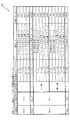
潜伏確変遊技状態ST2は、大当たり確率が通常遊技状態ST1の10倍高く(高確率遊技状態に)設定される遊技状態であり、第2特別図柄が実質変動対象となる遊技状態である。即ち、高確率遊技状態を継続可能な大当たりが発生する確率(確変割合)が高い遊技状態である。具体的には、第2特別図柄の変動時間が500ms(0.5秒)に設定される。これにより、潜伏確変遊技状態ST2では、右打ち遊技を行うことで、第2抽選遊技を効率よく行うことができる。そして、第2特別図柄の大当たりでは大当たり種別として、潜伏確変遊技状態ST2が継続(ループ)される大当たりC(15R確変大当たり)が66%の確率で選択され、確変遊技状態ST3へ移行される大当たりD(15R確変大当たり)が34%の確率で選択される。 The latent probability changing gaming state ST2 is a gaming state in which the jackpot probability is set 10 times higher than the normal gaming state ST1 (to a high probability gaming state), and the second special symbol is a gaming state that is a substantial variation target. That is, the gaming state has a high probability (probability change rate) that a jackpot capable of continuing the high probability gaming state is generated. Specifically, the variation time of the second special symbol is set to 500 ms (0.5 seconds). Thereby, in the latent probability changing game state ST2, the second lottery game can be efficiently performed by performing the right-handed game. Then, in the jackpot of the second special symbol, as a jackpot type, jackpot C (15R probability variation jackpot) in which the latent probability variation gaming state ST2 is continued (looped) is selected with a probability of 66%, and the jackpot transferred to the probability variation gaming state ST3 D (15R probability variation jackpot) is selected with a probability of 34%.
これに対し、潜伏確変遊技状態ST2では、実質変動対象ではない第1特別図柄の変動時間は長く設定される。具体的には、第1特別図柄の当否判定(抽選)結果が外れの場合には、変動時間は1800000ms(30分)が選択される(図18(a)参照)。よって、第1特別図柄の外れ変動が1回行われる間に、第2特別図柄では、最大3600回の抽選を実行することが可能となる。確変中(高確率遊技状態)での大当たり確率は、1/40であるので、通常の遊技であれば外れの第1特別図柄が1回変動終了するまでに、第2特別図柄で大当たりとすることができるように構成されている。一方、第1特別図柄の当否判定結果が当たりの場合には、変動時間は500ms(0.5秒)が選択される(図18(a)参照)。潜伏確変遊技状態ST2では、パチンコ機10をリセット(初期化)すると通常遊技状態ST1へ移行してしまうため、上述した不正行為(リセットゴト)を実行することができない。よって、第1特別図柄で大当たりとなった場合には、変動時間を500ms(0.5秒)と短く設定している。これにより、潜伏確変遊技状態ST2において第1特別図柄で大当たりが発生した場合にも、遊技の効率(回転率)を落とすことなく遊技を継続可能な遊技機にできる。
On the other hand, in the latent probability changing game state ST2, the variation time of the first special symbol that is not a substantial variation target is set to be long. Specifically, when the result of the first special symbol determination (lottery) is out of the range, 180000 ms (30 minutes) is selected as the variation time (see FIG. 18A). Therefore, it is possible to execute a lottery of a maximum of 3600 times in the second special symbol while the first special symbol is deviated once. Since the jackpot probability during probability change (high probability gaming state) is 1/40, if the game is a normal game, the second special symbol will be a jackpot before the first special symbol that has come off changes once It is configured to be able to. On the other hand, when the determination result of the first special symbol is a win, 500 ms (0.5 seconds) is selected as the variation time (see FIG. 18A). In the latent probability changing game state ST2, if the
また、詳細は後述するが、潜伏確変遊技状態ST2では、第2特別図柄の抽選結果として8/400の確率で小当たりとなるように構成されている。この潜伏確変遊技状態ST2における小当たりでは、第1可変入賞装置65の第1特定入賞口65aへ遊技球が約3球程度入球可能となっている。第1特定入賞口65aへの入球に基づいて払い出される賞球数は15球であるので、1回の小当たり遊技につき約45球が遊技者に対して払い出される。これにより、潜伏確変遊技状態ST2では、通常遊技状態ST1に比べて有利な状態(持ち球の消費が抑制された状態)で、右打ち遊技を実行することができる。
Further, as will be described in detail later, in the latent probability changing game state ST2, the lottery result of the second special symbol is configured to be a small hit with a probability of 8/400. In the small hit in the latent probability changing game state ST2, about 3 game balls can enter the first specific winning
潜伏確変遊技状態ST2において、第2特別図柄の大当たりとなり、大当たりD(15R確変大当たり)が選択されると、その後、再度、潜伏確変遊技状態ST2が設定される(ループ)する。一方、大当たりC(15R確変大当たり)が選択されると、その後には、確変電サポ有り遊技状態(確変遊技状態ST3)が設定される。 In the latent probability changing gaming state ST2, the second special symbol is a jackpot, and when the jackpot D (15R probability varying jackpot) is selected, the latent probability varying gaming state ST2 is set again (loop). On the other hand, when the jackpot C (15R probability variation jackpot) is selected, a gaming state with probability transformation support (probability gaming state ST3) is set thereafter.
確変遊技状態ST3は、特別図柄の抽選確率が10倍高く設定される(高確率遊技状態に設定される)遊技状態であり、第1特別図柄が実質変動対象となる遊技状態である。さらに、普通図柄の抽選確率も40倍高く設定され、普通図柄の変動時間も短い変動時間が選択され易くなる(図19参照)。また、第1普通電動役物632が特別状態(開状態)に維持される時間(開放時間)も通常遊技状態ST1、潜伏確変遊技状態ST2に比べて長く設定される。よって、右打ちした場合に、右第1始動口631に入賞し易く構成できる。本実施形態では、右打ちした遊技球の95%が右第1始動口631に入賞するように構成している。よって、残りの5%の遊技球のうちの85%が第2始動口640に入賞し、その残りの5%がアウト球となり消費される。よって、確変遊技状態では、右打ちされた遊技球のうち約99%が右第1始動口631または第2始動口640へ入賞することとなり、右打ちした遊技球の99%が賞球として遊技者に払い出される。よって、遊技者の持ち球の減少を抑制して遊技を行うことができる。
The probability variation gaming state ST3 is a gaming state in which the lottery probability of a special symbol is set 10 times higher (set to a high probability gaming state), and the first special symbol is a gaming state that is a substantial variation target. Further, the lottery probability of the normal symbol is set to be 40 times higher, and the fluctuation time of the normal symbol is also easily selected (see FIG. 19). In addition, the time during which the first ordinary
確変遊技状態ST3では、第2特別図柄の抽選結果として5/400の確率で小当たりとなるように構成されている。この確変遊技状態ST3における小当たりでは、第1可変入賞装置65の第1特定入賞口65aへの遊技球の入球が困難となっている。これにより、確変遊技状態ST3において、遊技者に対して有利となりすぎてしまうことを防止(抑制)できる。なお、これに限られず、第1特定入賞口65aへ遊技球が入球(例えば1球)可能としてもよい。これにより、遊技者に対する特典を増加させ、遊技者の興趣を向上させることができる。
In the probability variation gaming state ST3, the lottery result of the second special symbol is configured to be a small hit with a probability of 5/400. In the small hit in the probability variation game state ST3, it is difficult to enter a game ball into the first specific winning
確変遊技状態ST3では、実質変動対象でない第2特別図柄の変動時間は長く設定され、実質変動対象である第1特別図柄の変動時間は短く設定されている。具体的には、第2特別図柄の変動時間は、当否判定(抽選)結果に関わらず500ms(0.5秒)が選択される(図18(b)参照)。一方、第1特別図柄の変動時間は、当否判定(抽選)結果が外れの場合には、変動時間は1800000ms(30分)が選択される(図18(b)参照)。よって、第2特別図柄の外れ変動が1回行われる間に、第1特別図柄では、最大3600回の抽選を実行することが可能となる。確変中(高確率遊技状態)での大当たり確率は、1/40であるので、通常の遊技であれば外れの第2特別図柄が1回変動終了するまでに、第1特別図柄で大当たりとすることができるように構成されている。一方、第1特別図柄の当否判定(抽選)結果が当たりの場合には、変動時間は5000ms(5秒)が選択される(図18(b)参照)。上述したように、本パチンコ機10はリセット(初期化)すると通常遊技状態ST1へ移行してしまうため、上述した不正行為(リセットゴト)を実行することができない。よって、確変遊技状態ST3において第2特別図柄で大当たりとなった場合には、変動時間を5000ms(5秒)と短く設定している。これにより、確変遊技状態ST3において第2特別図柄で大当たりが発生した場合にも、遊技の効率(回転率)を落とすことなく遊技を継続可能な遊技機にできる。
In the probability variation gaming state ST3, the variation time of the second special symbol that is not the subject of substantial variation is set to be long, and the variation time of the first special symbol that is the subject of substantial variation is set to be short. Specifically, 500 ms (0.5 seconds) is selected as the variation time of the second special symbol regardless of the determination result (lottery) (see FIG. 18B). On the other hand, the variation time of the first special symbol is selected to be 1800000 ms (30 minutes) when the result of the determination (lottery) is off (see FIG. 18B). Therefore, it is possible to execute a lottery of a maximum of 3600 times for the first special symbol while the deviation variation of the second special symbol is performed once. The jackpot probability during probability change (high probability gaming state) is 1/40, so if it is a normal game, the first special symbol will be a big hit before the second special symbol that has been missed changes once It is configured to be able to. On the other hand, when the result of the first special symbol determination (lottery) is a win, 5000 ms (5 seconds) is selected as the variation time (see FIG. 18B). As described above, when the
また、上述したように、確変遊技状態ST3では、発射した遊技球のうち95%が右第1始動口631に入賞する。よって、第2始動口640へ遊技球が入球し難く、第2抽選遊技が実行され難いため、実質変動対象でない第2特別図柄の大当たりが発生することを抑制できる。
In addition, as described above, in the probability variation gaming state ST3, 95% of the launched gaming balls win the right first starting port 631. Therefore, since it is difficult for a game ball to enter the
確変遊技状態ST3で第1特別図柄の大当たりとなると、34%の割合で大当たりAが選択される。大当たりAに基づく大当たり遊技後には潜伏確変遊技状態ST2が設定(へ移行)される。よって、34%の確率で潜伏確変遊技状態ST2が選択(へ移行)されることとなり、再び最低2回の大当たりに当選するまでは、高確率で遊技を行うことが可能となる。一方、66%の確率で大当たりBが選択されると、大当たり遊技後に通常遊技状態ST1が設定される(所謂、転落する)ことになる。 When the first special symbol is a big hit in the probability variation gaming state ST3, the big hit A is selected at a rate of 34%. After the jackpot game based on the jackpot A, the latent probability changing game state ST2 is set (shifted to). Therefore, the latent probability changing game state ST2 is selected (shifted to) with a probability of 34%, and it becomes possible to play a game with a high probability until a win of at least two jackpots is won again. On the other hand, when the jackpot B is selected with a probability of 66%, the normal gaming state ST1 is set (so-called falling) after the jackpot game.
このように、本実施形態では、潜伏確変遊技状態ST2が設定されると、持ち球の消費が抑制された状態で、大当たりが2回実行されるまでは、遊技者に有利な高確率で第2抽選遊技(または第1抽選遊技)を実行することができる。よって、遊技者が通常遊技状態に比べて短期間で2回の大当たり遊技を実行できる可能性を高めることが可能となり、遊技者に優越感を提供することができるという効果がある。 As described above, in the present embodiment, when the latent probability changing game state ST2 is set, it is possible to increase the probability that is advantageous to the player until the jackpot is executed twice in a state where consumption of the holding ball is suppressed. Two lottery games (or first lottery games) can be executed. Therefore, it is possible to increase the possibility that the player can execute two jackpot games in a short period of time compared with the normal gaming state, and there is an effect that a superiority can be provided to the player.
さらに、大当たりが2回実行されるまで、遊技者に有利な高確率で抽選遊技が実行される旨を遊技者が把握できるよう表示することにより、遊技者に対して、最低2回の大当たりが保証されていると感じさせることができ、安心感を提供することができるという効果がある。 Further, by displaying the fact that the lottery game is executed with a high probability advantageous to the player until the jackpot is executed twice, the player can receive at least two jackpots for the player. There is an effect that it can feel assured and can provide a sense of security.
本実施形態では、潜伏確変遊技状態ST2において、第1特別図柄の大当たりBとなってしまうと、通常遊技状態ST1が設定(へ移行)されることとなる。即ち、2回の大当たりを得ることができない。潜伏確変遊技状態ST2では、上述したように第1抽選遊技が実行されにくい右打ち遊技が行われるようにしていると共に、長時間変動となる第1特別図柄の外れの変動中に、第2抽選遊技を複数回実行し、第2特別図柄の大当たりが発生する(し易い)ように構成されている(実質的に第1特別図柄の大当たりとならない)。しかし、潜伏確変遊技状態ST2において記憶されていた第1特別図柄の保留球などにより、第1特別図柄の大当たりとなってしまう場合がある。例えば、潜伏確変遊技状態ST2が設定された1回目の第2抽選遊技で大当たりとなる場合(1/40の確率)など。そこで、この場合には、潜伏確変遊技状態ST2において、第1特別図柄の大当たりとして34%の確率で大当たりAが選択され、66%の確率で大当たりEが選択されるように構成している(図7(b)、図16(b)参照)。大当たりAが選択されれば、その後高確率遊技状態である潜伏確変遊技状態ST2へ移行するので、2回の大当たりを得ることが可能となる。一方、大当たりEが選択された場合は、2回の大当たりを得ることができず、低確率状態へ移行される場合である。この場合には、大当たり遊技終了後に100回の時短遊技が付与されるようにしている。これにより、通常遊技状態ST1よりも遊技者に有利な状態が付与されるように構成されている。よって、遊技者が落胆して遊技への意欲が著しく低下する不具合を抑制できる。 In the present embodiment, in the latent probability changing game state ST2, when the big special bonus B of the first special symbol is reached, the normal game state ST1 is set (shifted to). In other words, two big hits cannot be obtained. In the latent probability changing game state ST2, as described above, a right-handed game in which the first lottery game is difficult to be executed is performed, and the second lottery is performed during the fluctuation of the first special symbol that changes for a long time. The game is executed a plurality of times, and the jackpot of the second special symbol is generated (easily) (substantially not the jackpot of the first special symbol). However, there may be a big hit of the first special symbol due to the holding ball of the first special symbol stored in the latent probability changing game state ST2. For example, in the case of a big win in the first second lottery game in which the latent probability changing game state ST2 is set (probability of 1/40). Therefore, in this case, in the latent probability changing game state ST2, the jackpot A is selected with a probability of 34% as the jackpot of the first special symbol, and the jackpot E is selected with a probability of 66% ( (Refer FIG.7 (b) and FIG.16 (b)). If the jackpot A is selected, the game proceeds to the latent probability changing gaming state ST2 which is a high probability gaming state, so that two jackpots can be obtained. On the other hand, when jackpot E is selected, two jackpots cannot be obtained, and a transition is made to a low probability state. In this case, 100 short-time games are awarded after the jackpot game ends. Thereby, it is comprised so that a state more advantageous to a player may be provided rather than normal game state ST1. Therefore, it is possible to suppress a problem that the player is discouraged and the willingness to play is significantly reduced.
図2に戻って説明を続ける。遊技領域には、球が入賞することにより5個から15個の球が賞球として払い出される複数の一般入賞口63が配設されている。また、遊技領域の中央部分には、可変表示装置ユニット80が配設されている。可変表示装置ユニット80には、第1始動口630、右第1始動口631、第2始動口640への入賞(始動入賞)をトリガとして、第1図柄表示装置37における変動表示と同期させながら、第3図柄(第1特別図柄、第2特別図柄)の変動表示を行う液晶ディスプレイ(以下単に「表示装置」と略す)で構成された第3図柄表示装置81が設けられている。
Returning to FIG. 2, the description will be continued. The game area is provided with a plurality of general winning
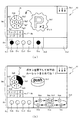
第3図柄表示装置81は8インチサイズの大型の液晶ディスプレイで構成されるものであり、表示制御装置114によって表示内容が制御されることにより、図4(a)に示すように、第1表示領域Dmに第3図柄の一つである第1特別図柄(特図1)または第2特別図柄(特図2)を示す、左(左側表示領域Dm1)、中(中表示領域Dm2)及び右(右側表示領域Dm3)の3つの図柄列が表示される。なお、第1表示領域(Dm)に表示される第3図柄の種別(特図1であるか、特図2であるか)は、遊技状態によって決定されて表示される。
The third
本実施形態では、通常遊技状態ST1(低確率遊技状態)と確変電サポ有り遊技状態(確変遊技状態)である場合には、第1特別図柄が第1表示領域Dmに表示され、確変電サポ無し遊技状態(潜伏確変遊技状態ST2)である場合には、第2特別図柄が第1表示領域Dmに表示されるように設定される。 In this embodiment, in the case of the normal gaming state ST1 (low probability gaming state) and the gaming state with probability transformation support (probability gaming state), the first special symbol is displayed in the first display area Dm, and the probability transformation support is provided. When the gaming state is none (latency probability changing gaming state ST2), the second special symbol is set to be displayed in the first display area Dm.
なお、本実施形態では、上記したように第1表示領域Dmに表示される特別図柄の種別が切り替えられるように設定したが、それに限らず、常に同じ特別図柄を表示するように構成してもよい。 In the present embodiment, the special symbol type displayed in the first display area Dm is set to be switched as described above. However, the present invention is not limited to this, and the same special symbol may be always displayed. Good.
各図柄列は複数の図柄によって構成され、これらの図柄が図柄列毎に縦スクロールして第3図柄表示装置81の第1表示領域Dm上にて第3図柄(第1特別図柄)が変動表示(動的表示)されるようになっている。
Each symbol row is composed of a plurality of symbols, and these symbols are vertically scrolled for each symbol row, and the third symbol (first special symbol) is displayed in a variable manner on the first display area Dm of the third
なお、第1表示領域Dmで表示される第3図柄(第1特別図柄または第2特別図柄)は、「0」から「9」の数字を付した10種類の特別図柄によりそれぞれ構成されている。また、本実施形態のパチンコ機10においては、後述する主制御装置110による抽選結果が大当たりであった場合に、同一の主図柄が揃う(例えば「777」)変動表示が行われ、その変動表示が終わった後に大当たりが発生するよう構成されている。
Note that the third symbol (the first special symbol or the second special symbol) displayed in the first display area Dm is composed of 10 types of special symbols with numbers “0” to “9”. . Further, in the
具体的には、第1表示領域Dmは、左・中・右のそれぞれ3つの図柄列Z1,Z2,Z3が表示される。各図柄列Z1〜Z3には、上述した第3図柄が規定の順序で表示される。即ち、各図柄列Z1〜Z3には、数字の昇順または降順に主図柄が配列され、各図柄列Z1〜Z3毎に周期性をもって上から下へとスクロールして変動表示が行われる。 Specifically, the first display area Dm displays three symbol rows Z1, Z2, and Z3 on the left, middle, and right, respectively. In each symbol row Z1 to Z3, the above-described third symbols are displayed in a prescribed order. That is, in each symbol row Z1 to Z3, main symbols are arranged in ascending order or descending order of numbers, and each symbol row Z1 to Z3 is scrolled from the top to the bottom with periodicity to perform variable display.
また、第1表示領域Dmには、有効ラインL1上に第3図柄が停止表示される。その第3図柄が有効ライン上に大当たり図柄の組合せ(本実施形態では、同一の主図柄の組合せ)で揃って停止されれば、大当たりとして大当たり動画が表示される。 In the first display area Dm, the third symbol is stopped and displayed on the effective line L1. If the third symbol is stopped with a combination of jackpot symbols on the active line (in this embodiment, the same main symbol combination), the jackpot moving image is displayed as a jackpot.
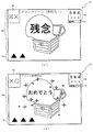
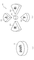
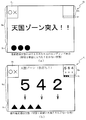
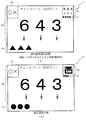
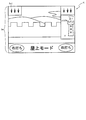
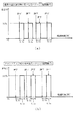
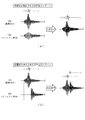
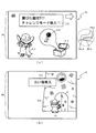
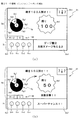
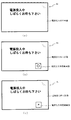
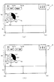
また、第1表示領域Dmの右上には、第2表示領域Dnとその下に第2副表示領域Dtが形成されている。この第2表示領域Dnには、第1特別図柄または第2特別図柄(遊技状態により異なる)を示す図柄列が表示される。また第2副表示領域Dtには、第2表示領域Dnに表示されている第1特別図柄または第2特別図柄(遊技状態により異なる)の保留球数を示す図柄が表示される。詳細については後述するが、確変遊技状態ST3である場合には、図9(a)〜(b)に示すように、第2特別図柄を示す第3図柄として、宝箱の図柄が第2表示領域Dnに表示される。そして第2特別図柄の変動が開始されると、図9(a)の状態と図9(b)の状態とを交互に短い周期(例えば1秒)で繰り替えし表示する点滅表示が実行される。そして、第2特別図柄の抽選結果が外れである場合には、変動時間が経過すると図9(a)で示す状態で停止表示される。一方、抽選結果が当たりである場合には、変動時間が経過すると図9(b)で示す状態で停止表示されるように構成されている。 A second display area Dn and a second sub display area Dt are formed below the second display area Dn at the upper right of the first display area Dm. In the second display area Dn, a symbol row indicating the first special symbol or the second special symbol (depending on the gaming state) is displayed. In the second sub display area Dt, a symbol indicating the number of reserved balls of the first special symbol or the second special symbol (which varies depending on the gaming state) displayed in the second display region Dn is displayed. Although details will be described later, in the case of the probability variation gaming state ST3, as shown in FIGS. 9A to 9B, the treasure box symbol is displayed in the second display area as the third symbol indicating the second special symbol. Dn is displayed. Then, when the variation of the second special symbol is started, a blinking display is performed in which the state of FIG. 9A and the state of FIG. 9B are alternately repeated with a short cycle (for example, 1 second). . Then, when the lottery result of the second special symbol is out of place, when the fluctuation time has elapsed, the lottery result is stopped and displayed in the state shown in FIG. On the other hand, when the lottery result is a win, the display is stopped and displayed in the state shown in FIG.
また、第1表示領域Dmの左上には、第3表示領域Duが形成されている。この第3表示領域Duには、図8(b)に示すような「○」、「×」の2種類の図柄列が並列して2列表示され、左側の図柄が第1特別図柄の抽選結果を示し、右側の図柄が第2特別図柄の抽選結果を示すように構成されている。なお、これに限られず、その他の態様によって第1特別図柄または第2特別図柄の抽選結果を示すようにしてもよい。例えば、「○」、「×」の2種類の図柄列が並列して2列表示され、「○」図柄が2つ左右列に表示されると、第1特別図柄または第2特別図柄(遊技状態により異なる)が当たりであったことを報知するように構成してもよい。また、第3表示領域Duと第2表示領域Dnとを共通化してもよい。例えば、通常遊技状態ST1では第2表示領域に「○」、「×」の2種類の図柄列が並列して2列表示するようにし、確変遊技状態ST3では、図9(a)〜(b)に示すように、第2特別図柄を示す第3図柄として、宝箱の図柄が第2表示領域Dnに表示するようにしてもよい。この場合には、大当たり遊技後に遊技状態が切り替えられるのに基づいて、表示領域が切り替えられるように構成すればよい。これにより、第1表示領域Dmの表示領域を広くすることができるので、第1表示領域Dmに表示される演出の演出効果を高めることができる。また、第2特別図柄に基づく変動が実行されていない場合(特図2の保留がない場合)には、第2表示領域Dnと、第2副表示領域Dtとを表示しないようにしてもよい。これにより、第1表示領域Dmの表示領域を広くすることができる。 A third display area Du is formed at the upper left of the first display area Dm. In the third display area Du, two types of symbol rows “◯” and “×” as shown in FIG. 8B are displayed in parallel, and the symbol on the left is the first special symbol lottery. A result is shown and it is comprised so that the symbol on the right side may show the lottery result of a 2nd special symbol. In addition, it is not restricted to this, You may make it show the lottery result of a 1st special symbol or a 2nd special symbol by another aspect. For example, when two types of symbol rows “○” and “×” are displayed in parallel and two “○” symbols are displayed in the left and right columns, the first special symbol or the second special symbol (game) You may comprise so that it may alert | report that it was a win. Further, the third display area Du and the second display area Dn may be shared. For example, in the normal gaming state ST1, two types of symbol rows “O” and “×” are displayed in parallel in the second display area, and in the probability changing gaming state ST3, FIGS. ) As shown in FIG. 3, the treasure box symbol may be displayed in the second display area Dn as the third symbol indicating the second special symbol. In this case, the display area may be switched based on the switching of the gaming state after the big hit game. Thereby, since the display area of the 1st display area Dm can be enlarged, the production effect of the effect displayed on the 1st display area Dm can be heightened. Moreover, when the fluctuation | variation based on a 2nd special symbol is not performed (when there is no suspension of special figure 2), you may make it not display 2nd display area Dn and 2nd sub display area Dt. . Thereby, the display area of the first display area Dm can be widened.
さらに、詳細については後述するが、本実施形態では、第1特別図柄と第2特別図柄との変動を同時に実行することが可能に構成されている。第1特別図柄と第2特別図柄とが同時に変動している場合に、一方が大当たり(または小当たり)を示す態様で停止表示されると、変動中の他方の特別図柄の変動も強制的に外れを示す態様で停止表示されるように構成されている。 Furthermore, although mentioned later for details, in this embodiment, it is comprised so that the fluctuation | variation with a 1st special symbol and a 2nd special symbol can be performed simultaneously. When the first special symbol and the second special symbol are changing at the same time, if one of them is stopped and displayed in a mode showing a big hit (or a small hit), the change of the other special symbol in the change is also forced It is configured so as to be stopped and displayed in a manner that indicates detachment.
ここで、大当たりでは第1可変入賞装置65の第1特定入賞口65aの開閉動作が15回(15ラウンドという)実行されるのに対して、小当たりでは、第1可変入賞装置65の第1特定入賞口65aの開閉動作が2回(例えば、2ラウンドという)実行される。また、大当たり遊技の1ラウンドは、30秒が経過するか、10球の遊技球が第1可変入賞装置65に入賞するまで実行される。これに対し、潜伏確変遊技状態ST2における小当たり遊技の1ラウンドは、1.8秒が経過するか、10球の遊技球が第1可変入賞装置65に入賞するまでに設定されている。よって、潜伏確変遊技状態ST2における小当たり遊技では、3球程度の遊技球が入球可能となっている。また、確変遊技状態ST3における小当たり遊技の1ラウンドは0.5秒が経過するか、10球の遊技球が第1可変入賞装置65に入賞するまでに設定されている。よって、確変遊技状態ST3における小当たり遊技では、ほとんど第1可変入賞装置65に遊技球を入球させることができず、賞球を得ることが困難に構成されている。
Here, in the big hit, the opening and closing operation of the first specific winning
確変遊技状態ST3においても、上述したように、第1特別図柄で小当たりを示す抽選結果で停止表示された場合には、変動中の第2特別図柄は強制的に外れを示す図柄(図9(a)参照)で停止表示される。この場合には、長時間(10分)の変動である実質変動対象でない第2特別図柄の外れ変動が停止され、特図1の小当たり遊技が終了した後、特図1の新たな変動と同時に、第2特別図柄の新たな保留(次の保留)球に基づいて第2抽選遊技が実行される。即ち、第2特別図柄に基づく大当たりが発生する可能性がある。本実施形態では、第2特別図柄での第2抽選遊技で大当たりとなった場合には、高確率遊技状態へ移行可能な大当たりC(15R確変大当たり)が必ず(100%)選択されるように構成されており(図16(c)参照)、遊技者に有利な場合となっている。よって、第2特別図柄の新たな保留(次の保留)に基づいて変動が開始される場合には、図10(a)〜(b)に示すように、第2表示領域Dnに第1特別図柄の変動が表示され、第1表示領域Dmに第2特別図柄の変動が表示されるように可変される。同様にして第1特別図柄の保留球数を示す図柄が第2副表示領域Dtに表示され、第2特別図柄の保留球数を示す図柄が副表示領域Dsに表示されるように可変される。なお、可変される態様としてはこれに限られず、第2特別図柄の変動が表示されている第2表示領域Dnの表示領域を拡大し、第1特別図柄の変動が表示されている第1表示領域Dmを縮小するようにしてもよい。 Even in the probable gaming state ST3, as described above, when the first special symbol is stopped and displayed in the lottery result indicating the small hit, the changing second special symbol is forcibly removed (FIG. 9). (See (a)). In this case, after the extra fluctuation of the second special symbol that is not subject to substantial fluctuation, which is a fluctuation for a long time (10 minutes), is stopped and the small hit game of special figure 1 ends, At the same time, the second lottery game is executed based on the new hold (next hold) ball of the second special symbol. That is, there is a possibility that a jackpot based on the second special symbol occurs. In this embodiment, when a big hit is made in the second lottery game with the second special symbol, the big hit C (15R probability variable big hit) that can be shifted to the high probability gaming state is always selected (100%). It is configured (see FIG. 16C), which is advantageous to the player. Therefore, when the change starts based on a new hold (next hold) of the second special symbol, as shown in FIGS. 10 (a) to 10 (b), the second special display area Dn has the first special display. The variation of the symbol is displayed, and the variation of the second special symbol is displayed in the first display area Dm. Similarly, a symbol indicating the number of reserved balls of the first special symbol is displayed in the second sub-display area Dt, and a symbol indicating the number of reserved balls of the second special symbol is displayed in the sub-display area Ds. . Note that the mode of change is not limited to this, and the display area of the second display area Dn in which the variation of the second special symbol is displayed is enlarged, and the first display in which the variation of the first special symbol is displayed. The area Dm may be reduced.
第1表示領域Dmに第2特別図柄の変動が表示されるように可変されると、宝箱が開く表示態様が実行され、当否判定結果が外れである場合には図10(a)に示すように「残念」の文字が宝箱の中より表示されて、遊技者に抽選結果が外れであったことが表示される。一方、当否判定結果が当たりである場合には、図10(b)に示すように「おめでとう」の文字が宝箱の中より表示されて、遊技者に抽選結果が当たりであったことが表示される。 When the first display area Dm is changed so that the variation of the second special symbol is displayed, a display mode in which the treasure box is opened is executed, and when the result of the determination is wrong, as shown in FIG. "Sorry" is displayed from the treasure box, and the player is informed that the lottery result has been missed. On the other hand, if the determination result is a win, as shown in FIG. 10B, the word “congratulations” is displayed from the treasure box, and the player is shown that the lottery result is a win. The
このように、確変遊技状態ST3において、第1特別図柄が小当たりに当選すると、第2特別図柄の変動は強制的に停止表示され、新たな第2特別図柄の変動が開始されるので、第2抽選遊技が実行される機会を増やすことができる。さらに、その場合には、図10(a)〜図10(b)に示すように第2特別図柄に基づく変動が強調して表示されるので、遊技者に第2特別図柄での大当たりを期待させることができる。 As described above, in the probability variation gaming state ST3, when the first special symbol is won in the small hit, the variation of the second special symbol is forcibly stopped and the variation of the new second special symbol is started. The chance that 2 lottery games are executed can be increased. Further, in that case, as shown in FIGS. 10 (a) to 10 (b), the fluctuation based on the second special symbol is highlighted and displayed, so the player is expected to win a big hit with the second special symbol. Can be made.
本実施形態の第3図柄表示装置81は、主制御装置110の制御に伴った遊技状態の表示が第1図柄表示装置37で行われるのに対して、その第1図柄表示装置37の表示に応じた装飾的な表示を行うものである。なお、表示装置に代えて、例えば、リール等を用いて第3図柄表示装置81を構成するようにしても良い。
In the third
図8(a)に示すように、第1表示領域Dmの下方には、副表示領域Dsが形成される。この副表示領域Dsには、図8(b)に示すように、第1特別図柄に対応した保留図柄「黒い丸印」が表示される。一方、第2表示領域Dnの下方には、第2副表示領域Dtが形成される。この第2副表示領域Dtには、図9(a)に示すように、第2特別図柄に対応した保留図柄「黒い三角印」が表示される。本実施形態では、第1特別図柄と第2特別図柄との保留球数はそれぞれ4個に設定されているので、副表表示領域Dsには、保留図柄「黒い丸印」が最大4個表示され、第2副表示領域Dtには、保留図柄「黒い三角印」が最大4個表示される。 As shown in FIG. 8A, a sub display area Ds is formed below the first display area Dm. In the sub display area Ds, as shown in FIG. 8B, a reserved symbol “black circle” corresponding to the first special symbol is displayed. On the other hand, a second sub display area Dt is formed below the second display area Dn. In the second sub display area Dt, as shown in FIG. 9A, a reserved symbol “black triangle mark” corresponding to the second special symbol is displayed. In the present embodiment, since the number of reserved balls for the first special symbol and the second special symbol is set to four, a maximum of four reserved symbols “black circles” are displayed in the sub-table display area Ds. In the second sub display area Dt, a maximum of four reserved symbols “black triangles” are displayed.
なお、本実施形態では、第1特別図柄の保留図柄を「黒い丸印」、第2特別図柄の保留図柄を「黒い三角印」で区別して表示するようにしている。なお、これに限られず、第1特別図柄と第2特別図柄との保留図柄は同一としてもよい。第1特別図柄と第2特別図柄とで同一の保留図柄を利用することで、図柄データの容量を低減させることができる。さらに、副表示領域Dsに第1特別図柄の保留図柄と第2特別図柄の保留図柄とを表示するようにしてもよい。例えば、副表示領域Dsの左側領域に第1特別図柄の保留図柄を表示し、右側領域に第2特別図柄の保留図柄を表示するようにしてもよいし、表示領域の左側から変動開始される順に保留図柄が並ぶように表示してもよい。 In the present embodiment, the reserved symbol of the first special symbol is displayed as a “black circle”, and the reserved symbol of the second special symbol is distinguished as a “black triangle”. However, the present invention is not limited to this, and the reserved symbols of the first special symbol and the second special symbol may be the same. By using the same reserved symbol for the first special symbol and the second special symbol, the capacity of the symbol data can be reduced. Furthermore, the reserved symbol of the first special symbol and the reserved symbol of the second special symbol may be displayed in the sub display area Ds. For example, the reserved symbol of the first special symbol may be displayed in the left area of the sub display area Ds, and the reserved symbol of the second special symbol may be displayed in the right area, or the variation starts from the left side of the display area. You may display so that a pending | holding symbol may line up in order.
また、本実施形態では、第1抽選遊技と第2抽選遊技の2つで構成されたパチンコ機10について説明したが、それに限らず、3つや4つ、それ以上の抽選遊技とそれに対応する始動口をそれぞれ設けて、同時にそれぞれの抽選結果の変動表示を可能に構成するようにしても当然良い。
In the present embodiment, the
第1始動口630、右第1始動口631、第2始動口640へ遊技球が入賞すると遊技盤13の裏面側に設けられる第1始動口スイッチまたは第2始動口スイッチ(図示せず)がオンとなる。なお、第1始動口630と右第1始動口631とは入球した遊技球が第1始動口スイッチへと誘導される共通の誘導路が遊技盤13の背面側に形成されている。第1始動口スイッチ、第2始動口スイッチのオンに起因して主制御装置110で大当たりの抽選がなされ、その抽選結果に応じた表示が第1図柄表示装置37で示される。また、第1始動口630、右第1始動口631、第2始動口640は、球が入賞すると1個の球が賞球として払い出される入賞口の1つにもなっている。
When a game ball wins the
第1特別図柄と第2特別図柄とのどちらか一方が、大当たりを示す図柄で停止表示されると、他方の特別図柄に基づく変動表示は、強制的に変動が終了される。なお、本実施形態では、一方の特別図柄で当否判定結果が大当たりとなる変動が開始されている場合には、他方の後から変動開始される特別図柄は、強制的に外れの抽選結果として変動が開始されるように構成されている。これにより、大当たり遊技が連続して開始されたり、同時に大当たり遊技が開始される不具合を抑制できる。 When either one of the first special symbol and the second special symbol is stopped and displayed with the symbol indicating the jackpot, the variation display based on the other special symbol is forcibly terminated. In the present embodiment, when a variation in which the determination result is a big hit is started in one special symbol, the special symbol that starts to vary after the other symbol is forcibly changed as a lottery result. Is configured to start. Thereby, the malfunction that a jackpot game is started continuously or a jackpot game is started simultaneously can be suppressed.
なお、本実施形態では、一方の特別図柄で当たりの抽選遊技が実行されている場合には、他方では外れの抽選遊技が強制的に実行されるように構成したが、それに限らず、他方でも抽選結果通りの抽選遊技を実行して、連続して大当たり遊技が開始されることが可能に構成してもよい。また、第1特別図柄と第2特別図柄とのどちらか一方で大当たりとなった場合には、他方の特別図柄において変動時間の計測を中断して、大当たり後に残りの変動表示を継続する構成としてもよい。この場合、中断中については、所定周期で、第1特別図柄または第2特別図柄について、所定の表示態様「例えば、アルファベットのh」で停止表示させた状態で点滅表示させたりしてもよい。このように、構成することで、第1特別図柄または第2特別図柄が仮停止中(中断中)であることを遊技者に報知することができる。 In the present embodiment, when the winning lottery game is executed with one special symbol, the other lottery game is forcibly executed on the other side. You may comprise so that the lottery game as a lottery result may be performed and a jackpot game may be started continuously. In addition, when one of the first special symbol and the second special symbol is a big hit, the measurement of the variation time is interrupted in the other special symbol, and the remaining fluctuation display is continued after the big hit. Also good. In this case, during interruption, the first special symbol or the second special symbol may be blinked and displayed in a predetermined display mode “for example, alphabet h” in a predetermined cycle. By configuring in this way, it is possible to notify the player that the first special symbol or the second special symbol is temporarily stopped (suspended).
また、各遊技状態において優先的に変動表示を実行する特別図柄を規定し、その特別図柄の変動表示が優先的に実行されるようにしてもよい。例えば、通常遊技状態ST1において、第1特別図柄の変動を優先的に実行するようにする。この場合は、第1特別図柄の変動の実行開始に基づいて第2特別図柄の変動が仮停止(または強制停止)されるようにすればよい。これにより、第1特別図柄が変動していなければ第2特別図柄の変動が実行可能であるが、第1特別図柄の変動が開始される場合には第2特別図柄の変動が仮停止(または強制停止)される。よって、通常遊技状態ST1において第1特別図柄の変動を優先的に実行することができる。 Further, a special symbol that preferentially executes the variable display in each gaming state may be defined, and the variable symbol display of the special symbol may be preferentially executed. For example, in the normal gaming state ST1, the first special symbol change is preferentially executed. In this case, the second special symbol may be temporarily stopped (or forcedly stopped) based on the start of execution of the first special symbol variation. As a result, if the first special symbol has not changed, the second special symbol can be changed. However, when the first special symbol starts to change, the second special symbol changes temporarily (or Forced stop). Therefore, the change of the first special symbol can be preferentially executed in the normal gaming state ST1.
遊技盤13の下側における左右の隅部には、証紙や識別ラベル等を貼着するための貼着スペースK1,K2が設けられ、貼着スペースK1に貼られた証紙等は、前面枠14の小窓35(図1参照)を通じて視認することができる。
Adhesive spaces K1 and K2 for adhering certificate stamps, identification labels, and the like are provided at the left and right corners on the lower side of the
更に、遊技盤13には、アウト口66が設けられている。いずれの入賞口にも入賞しなかった球はアウト口66を通って図示しない球排出路へと案内される。遊技盤13には、球の落下方向を適宜分散、調整等するために多数の釘が植設されているとともに、風車等の各種部材(役物)が配設されている。
Further, the
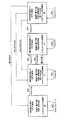
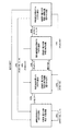
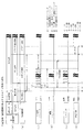
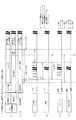
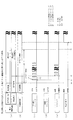
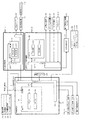
図3に示すように、パチンコ機10の背面側には、制御基板ユニット90、91と、裏パックユニット94とが主に備えられている。制御基板ユニット90は、主基板(主制御装置110)と音声ランプ制御基板(音声ランプ制御装置113)と表示制御基板(表示制御装置114)とが搭載されてユニット化されている。制御基板ユニット91は、払出制御基板(払出制御装置111)と発射制御基板(発射制御装置112)と電源基板(電源装置115)とカードユニット接続基板116とが搭載されてユニット化されている。
As shown in FIG. 3,
裏パックユニット94は、保護カバー部を形成する裏パック92と払出ユニット93とがユニット化されている。また、各制御基板には、各制御を司る1チップマイコンとしてのMPU、各種機器との連絡をとるポート、各種抽選の際に用いられる乱数発生器、時間計数や同期を図る場合などに使用されるクロックパルス発生回路等が、必要に応じて搭載されている。
The
なお、主制御装置110、音声ランプ制御装置113及び表示制御装置114、払出制御装置111及び発射制御装置112、電源装置115、カードユニット接続基板116は、それぞれ基板ボックス100〜104に収納されている。基板ボックス100〜104は、ボックスベースと該ボックスベースの開口部を覆うボックスカバーとを備えており、そのボックスベースとボックスカバーとが互いに連結されて、各制御装置や各基板が収納される。
The
また、基板ボックス100(主制御装置110)及び基板ボックス102(払出制御装置111及び発射制御装置112)は、ボックスベースとボックスカバーとを封印ユニット(図示せず)によって開封不能に連結(かしめ構造による連結)している。また、ボックスベースとボックスカバーとの連結部には、ボックスベースとボックスカバーとに亘って封印シール(図示せず)が貼着されている。この封印シールは、脆性な素材で構成されており、基板ボックス100,102を開封するために封印シールを剥がそうとしたり、基板ボックス100,102を無理に開封しようとすると、ボックスベース側とボックスカバー側とに切断される。よって、封印ユニット又は封印シールを確認することで、基板ボックス100,102が開封されたかどうかを知ることができる。
Further, the substrate box 100 (main control device 110) and the substrate box 102 (dispensing
払出ユニット93は、裏パックユニット94の最上部に位置して上方に開口したタンク130と、タンク130の下方に連結され下流側に向けて緩やかに傾斜するタンクレール131と、タンクレール131の下流側に縦向きに連結されるケースレール135と、ケースレール135の最下流部に設けられ、払出モータ216(図8参照)の所定の電気的構成により球の払出を行う払出装置133とを備えている。タンク130には、遊技ホールの島設備から供給される球が逐次補給され、払出装置133により必要個数の球の払い出しが適宜行われる。タンクレール131には、当該タンクレール131に振動を付加するためのバイブレータ134が取り付けられている。
The
また、払出制御装置111には状態復帰スイッチ120が設けられ、発射制御装置112には可変抵抗器の操作つまみ121が設けられ、電源装置115にはRAM消去スイッチ(図3、122)が設けられている。状態復帰スイッチ120は、例えば、払出モータ216(図12参照)部の球詰まり等、払出エラーの発生時に球詰まりを解消(正常状態への復帰)するために操作される。操作つまみ121は、発射ソレノイドの発射力を調整するために操作される。RAM消去スイッチ(図3、122)は、パチンコ機10を初期状態に戻したい場合に電源投入時に操作される。
The
<構成について>
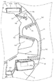
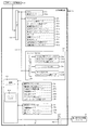
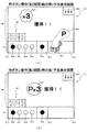
図2を参照して、さらに本実施形態の特徴的な構成について詳細を説明する。本実施形態では、可変表示装置ユニット80の左側を遊技球が流下する左側流路PA1と、可変表示装置ユニット80の右側を流下する右側流路PA2とが形成されている。可変表示装置ユニット80の中央下方には、第1始動口630が配置されている。上述したように、右側流路PA2を流下する遊技球は釘群T2およびT3によって、流下する遊技球のうち85%が第2始動口640へ入球するように構成されている。よって、第1始動口630へは、左側流路PA1を流下した遊技球が、右側流路PA2を流下した遊技球よりも入球し易く構成されている。
<About configuration>
With reference to FIG. 2, the characteristic configuration of the present embodiment will be further described in detail. In the present embodiment, a left channel PA1 in which the game ball flows down on the left side of the variable
右側流路PA2には、第1普通図柄始動口67aが配置されており、その下方に第1可変入賞装置65が配置され、その下方に右第1始動口631が配置され、その右側に第2普通図柄始動口67bが配置されている。右第1始動口631の下方には、第2始動口640が配置されている。遊技盤13には遊技球の転動方向を可変させるための複数の釘Tが配置されている。
A first normal
右側流路に発射された遊技球は、釘群T4(3本の釘により構成)により第1普通電動役物632が通常状態(左誘導部材632aと右誘導部材632bとが起立した状態)では、右第1始動口631に遊技球が入球しないように構成されている。第1普通電動役物632が通常状態である場合には、右側流路を流下する遊技球の85%が右第1始動口631の左側を流下するように構成されている。なお、右第1始動口631の左側と右側とを流下する遊技球の割合は、釘T1の角度(傾き)を調整することで変更が可能に構成されている。釘T1の角度を第1可変入賞装置65側(釘群T4と反対側)に傾斜させることで、釘T1と釘群T4との幅が広くなり、釘T1と釘群T4との間を流下する、即ち、右第1始動口631の右側を遊技球が流下する割合が増す。一方、釘T1を右第1始動口631側(釘群T4側)に傾斜させることで、釘T1と釘群T4との幅が狭くなり、右第1始動口631の右側を遊技球が流下する割合が減ることで、右第1始動口631の左側を流下する遊技球の割合を増やすことができる。
The game balls launched into the right channel are in the normal state (the
右第1始動口631の左側を流下した遊技球は、釘群T3(5本の釘により構成)により第2始動口640へと誘導されるように構成されている。なお、釘群T3は、それぞれの釘の幅が遊技球1球分よりも狭く配置されており、その間(幅)を遊技球が通過不可能に構成されている。釘群T3に誘導された遊技球は、釘群T2(3本の釘で構成)により第2始動口640の下方へ流下することが妨げられ、すべて第2始動口640に入球するように構成されている。なお、これに限られず、一部の遊技球が釘群T3側(または釘群T2側、またはその両方)から下方へ流下するようにしても当然よい。
The game ball that has flowed down the left side of the right first starting port 631 is configured to be guided to the
ここで、本実施形態では、第2始動口640に遊技球が入球すると遊技者に対して、1球の賞球が払い出されるように設定されている。右側流路PA2に発射された遊技球の85%は、第2始動口640に入賞するように構成されている(第1普通電動役物632が通常状態である場合)ので、遊技者が発射した遊技球のうち、85%は賞球として払い戻されるように構成されている。よって、遊技者は、右側流路PA2に遊技球を発射することで、左側流路に遊技球を発射するよりも持ち球としての遊技球の消費(減少)を抑制することができる。なお、本実施形態では、右第1始動口631の右側を流下した遊技球は、釘群T2により第2始動口640には入賞しない構成となっている。これにより、釘T1を調整することにより、第2始動口640へ入球する遊技球の割合、即ち、右打ち遊技において賞球として払い戻される割合を調整することができる。
Here, in this embodiment, when a game ball enters the
次に、第1普通電動役物632が特別状態(左誘導部材632aと右誘導部材632bとが略水平となるまで回動した状態、開状態)では、左誘導部材632aにより右第1始動口631の左側を流下する流路が閉鎖されるように構成されている。これにより、電動役物632が特別状態(開状態)である場合には、右側流路を流下した遊技球が第2始動口640に入賞することが抑制されるように構成されている。よって、時短遊技状態ST1hや確変遊技状態ST3である時には、右第1始動口631への入賞が増し、第2始動口640への入賞が減少して第1特別図柄での第1抽選遊技の実行回数(実行頻度)が多くなるように構成されている。さらに、時短遊技状態ST1hと確変遊技状態ST3では、第2特別図柄の変動時間が長く設定されるので、より第2抽選遊技の実行回数(実行頻度)を少なく(低く)することができる。
Next, when the first ordinary
さらに、本実施形態では、潜伏確変遊技状態ST2では、遊技者に有利となる第2特別図柄の変動時間が短く設定されるので、右側流路に遊技球を発射するように遊技が行われるが、既に述べたように、第2始動口640へ入賞する遊技球の割合は、右側流路を流下する遊技球の85%に設定されているので、遊技者の持ち球は減少していく。しかしながら、本実施形態では、潜伏確変遊技状態ST2となると、第2特別図柄で小当たりに当選する確率が高く設定される。さらに、潜伏確変遊技状態ST2中に実行される小当たり遊技は第1可変入賞装置65の1ラウンドの開放時間が1.8秒または10球入賞するまでに設定され、1ラウンド当たりの開放時間が他の遊技状態における小当たりよりも延長されるので、小当たりにより賞球を得ることができる。本実施形態では、潜伏確変中の小当たりの確率が、右側流路を流下して消費される15%分となるように設定されており、遊技者の持ち球の減少を補填するように構成されている。よって、潜伏確変遊技状態ST2にも遊技者は、持ち球が減少するのを抑制して遊技を行うことができる。
Further, in the present embodiment, in the latent probability changing game state ST2, since the variation time of the second special symbol that is advantageous to the player is set short, the game is performed so as to fire the game ball in the right channel. As already described, since the ratio of the game balls winning the
なお、本実施形態では、通常遊技状態ST1では、右打ち遊技(右側流路PA2に遊技球を発射して遊技)で遊技を行うことが禁止されており、通常遊技状態ST1時に第2始動口640に遊技球が入賞すると異常処理が実行されて、第3図柄表示装置81に警報表示「左打ちで遊技してください」という文字を表示するとともに、音声でも同様の警告が報知される。また、通常遊技状態ST1で、第2始動口640に遊技球が入賞した場合には、大当たりが無効となるように制御してもよいし、ホールコンピュータ等に異常信号を出力するように構成してもよい。
In the present embodiment, in the normal game state ST1, it is prohibited to play a right-handed game (a game by launching a game ball into the right flow path PA2), and the second start port in the normal game state ST1. When a game ball wins at 640, abnormal processing is executed, and a warning display “Please play left-handed” is displayed on the third
本実施形態では、各遊技状態で遊技方法(左打ち遊技または右打ち遊技)を変更するように構成したが、これに限られるものではない。全ての遊技状態において左打ち遊技または右打ち遊技のどちらを行っても良いように構成してもよいし、特定の遊技状態において左打ち遊技または右打ち遊技のどちらを行っても良いように構成してもよい。例えば、第1特別図柄の始動口と、第2特別図柄の始動口を遊技盤13の中央下部に設ける。そして、左打ち遊技を行うことで左側流路PA1を流下する遊技球と、右打ち遊技を行うことで、右側流路PA2を流下する遊技球とが第1特別図柄の始動口と、第2特別図柄の始動口へ入球可能となるように構成すればよい。これにより、全ての遊技状態または特定の遊技状態において、左打ち遊技と右打ち遊技とに打ち分ける必要がなくなるので、遊技者の遊技負担を軽減することができる。
In the present embodiment, the game method (left-handed game or right-handed game) is changed in each gaming state, but the present invention is not limited to this. Either left-handed game or right-handed game may be performed in all gaming states, or left-handed game or right-handed game may be performed in a specific gaming state May be. For example, a starting port for a first special symbol and a starting port for a second special symbol are provided at the lower center of the
<第1実施形態における電気的構成>
次に、図12を参照して、本パチンコ機10の電気的構成について説明する。図12は、パチンコ機10の電気的構成を示すブロック図である。主制御装置110には、演算装置である1チップマイコンとしてのMPU201が搭載されている。MPU201には、該MPU201により実行される各種の制御プログラムや固定値データを記憶したROM202と、そのROM202内に記憶される制御プログラムの実行に際して各種のデータ等を一時的に記憶するためのメモリであるRAM203と、そのほか、割込回路やタイマ回路、データ送受信回路などの各種回路が内蔵されている。なお、払出制御装置111や音声ランプ制御装置113などのサブ制御装置に対して動作を指示するために、主制御装置110から該サブ制御装置へ各種のコマンドがデータ送受信回路によって送信されるが、かかるコマンドは、主制御装置110からサブ制御装置へ一方向にのみ送信される。
<Electric Configuration in First Embodiment>
Next, the electrical configuration of the
主制御装置110では、大当たり抽選や第1図柄表示装置37および第3図柄表示装置81における表示の設定、第2図柄表示装置83における表示結果の抽選といったパチンコ機10の主要な処理を実行する。RAM203には、これらの処理を制御するための各種カウンタを格納するカウンタ用バッファ(図13参照)が設けられている。
The
ここで、図13を参照して、主制御装置110のRAM203内に設けられるカウンタ等について説明する。これらのカウンタ等は、大当たり抽選や第1図柄表示装置37および第3図柄表示装置81の表示の設定、第2図柄表示装置83の表示結果の抽選などを行うために、主制御装置110のMPU201で使用される。
Here, a counter and the like provided in the
大当たり抽選や第1図柄表示装置37および第3図柄表示装置81の表示の設定には、大当たりの抽選に使用する第1当たり乱数カウンタC1と、大当たり図柄の選択に使用する第1当たり種別カウンタC2と、変動パターンの選択に使用する変動種別カウンタC3と、第1当たり乱数カウンタC1の初期値設定に使用する第1初期値乱数カウンタCINI1とが用いられる。また、普通図柄(第2図柄表示装置83)の抽選には、第2当たり乱数カウンタC4が用いられ、第2当たり乱数カウンタC4の初期値設定には第2初期値乱数カウンタCINI2が用いられる。これら各カウンタは、更新の都度前回値に1が加算され、最大値に達した後0に戻るループカウンタとなっている。
For the jackpot lottery and display settings of the first
各カウンタは、例えば、タイマ割込処理(図22参照)の実行間隔である2ミリ秒間隔で更新され、また、一部のカウンタは、メイン処理(S1600)(図45参照)の中で不定期に更新されて、その更新値がRAM203の所定領域に設定されたカウンタ用バッファに適宜格納される。詳細については後述するが、RAM203には、第1始動口630と右第1始動口631に対する入賞について各カウンタ値が格納される第1特別図柄保留球格納エリア203aと第2始動口640に対する入賞について各カウンタ値が格納される第2特別図柄保留球格納エリア203bとが設けられている。本実施形態では、第1始動口630と右第1始動口631とで合わせて保留球が最大4個、第2始動口640には、保留球が最大4個までそれぞれ設けられており、合計最大8個の保留球が記憶可能に構成されている。そのため、特別図柄が変動表示中でない場合や、特別図柄の大当たり遊技中でない場合等の特別図柄の抽選が可能な期間に遊技球が、第1始動口630または右第1始動口631に遊技球が入賞すると、各カウンタ値が第1特別図柄保留球格納エリア203aに格納され、第2始動口640に遊技球が入賞すると、各カウンタ値が第2特別図柄保留球格納エリア203bに格納される。その後、第1特別図柄保留球格納エリア203aに格納された各カウンタ値が第1特別図柄保留球実行エリア(図示せず)に移動されて、第1特別図柄を変動表示(動的表示)するための各種設定や制御処理が実行される。同様にして、第2特別図柄保留球格納エリア203bに格納された各カウンタ値が第2特別図柄保留球実行エリア(図示せず)に移動されて、第2特別図柄を変動表示するための各種設定や制御処理が実行される。
Each counter is updated, for example, at an interval of 2 milliseconds, which is the execution interval of the timer interrupt process (see FIG. 22), and some counters are not included in the main process (S1600) (see FIG. 45). It is updated periodically and the updated value is appropriately stored in a counter buffer set in a predetermined area of the
一方、第1特別図柄または第2特別図柄の変動表示中や第1特別図柄または第2特別図柄の大当たり遊技中等の特別図柄の抽選が不可能な期間に、遊技球が第1始動口630または右第1始動口631、第2始動口640に入賞した場合には、入賞した始動口に対する保留個数が上限値(本実施形態では、4個)未満である場合には、各カウンタ値の取得がされ、入賞した始動口に対応する第1特別図柄保留球格納エリア203aまたは第2特別図柄保留球格納エリア203bに記憶される。また、入賞した始動口に対する保留個数が上限値(本実施形態では、4個)以上である場合には、各カウンタ値等の取得はされずに賞球(本実施例では、遊技球1個)のみが遊技者に払い出される無効球として扱われる。
On the other hand, during the period when the special symbol lottery is not possible, such as during the fluctuation display of the first special symbol or the second special symbol or during the jackpot game of the first special symbol or the second special symbol, When winning at the right first start port 631 and the
なお、本実施形態では、保留球数の上限値は、第1始動口630と右第1始動口631で合わせて4個、第2始動口640とに対して4個としたが、それに限らず、それぞれ4個でもよいし、上限値をもうけないようにしてもよい。
In the present embodiment, the upper limit value of the number of reserved balls is four for the
図9に示す各カウンタについて詳しく説明する。第1当たり乱数カウンタC1は、所定の範囲(例えば、0〜399)内で順に1ずつ加算され、最大値(例えば、0〜399の値を取り得るカウンタの場合は399)に達した後0に戻る構成となっている。特に、第1当たり乱数カウンタC1が1周した場合、その時点の第1初期値乱数カウンタCINI1の値が当該第1当たり乱数カウンタC1の初期値として読み込まれる。なお、この第1当たり乱数カウンタC1は、第1始動口630または右第1始動口631、第2始動口640への入球に対してそれぞれ共通に取得される。
Each counter shown in FIG. 9 will be described in detail. The first random number counter C1 is incremented one by one within a predetermined range (for example, 0 to 399) and reaches 0 after reaching the maximum value (for example, 399 in the case of a counter that can take a value of 0 to 399). It is the composition which returns to. In particular, when the first random number counter C1 makes one round, the value of the first initial value random number counter CINI1 at that time is read as the initial value of the first random number counter C1. Note that the first random number counter C1 is acquired in common for each of the
第1初期値乱数カウンタCINI1は、第1当たり乱数カウンタC1と同一範囲で更新されるループカウンタとして構成される。即ち、例えば、第1当たり乱数カウンタC1が0〜399の値を取り得るループカウンタである場合には、第1初期値乱数カウンタCINI1もまた、0〜399の範囲のループカウンタである。この第1初期値乱数カウンタCINI1は、タイマ割込処理(図22参照)の実行毎に1回更新されると共に、メイン処理(S1600)(図45参照)の残余時間内で繰り返し更新される。 The first initial value random number counter CINI1 is configured as a loop counter that is updated in the same range as the first random number counter C1. That is, for example, when the first random number counter C1 is a loop counter that can take a value of 0 to 399, the first initial value random number counter CINI1 is also a loop counter in the range of 0 to 399. The first initial value random number counter CINI1 is updated once every time the timer interrupt process (see FIG. 22) is executed, and is repeatedly updated within the remaining time of the main process (S1600) (see FIG. 45).
第1当たり乱数カウンタC1の値は、例えば定期的に(本実施形態ではタイマ割込処理毎に1回)更新され、球が第1始動口630、右第1始動口631、第2始動口640に入賞(始動入賞)したタイミングで、RAM203の入賞した始動口に対応する第1特別図柄保留球格納エリア203aまたは第2特別図柄保留球格納エリア203bに格納される。大当たりとなる乱数の値は、主制御装置110のROM202に格納される第1当たり乱数テーブル202a(図14参照)によって設定されており、第1当たり乱数カウンタC1の値が、第1当たり乱数テーブル202aによって設定された大当たりとなる乱数の値(本実施形態では、低確率時には、「7」、高確率時には、「0〜9」)と一致する場合に、大当たりと判定する。
The value of the first per-random number counter C1 is updated, for example, periodically (in this embodiment, once for each timer interrupt process), and the balls are the
本実施形態のパチンコ機10における第1当たり乱数カウンタC1は、0〜399の範囲の2バイトのループカウンタとして構成されている。この第1当たり乱数カウンタC1では、大当たりとなる乱数の値(当たり値)の数は低確率時には1で、その値「7」が、高確率時には10で、その値「0〜9」が、第1当たり乱数テーブル202aに格納されている。
The first random number counter C1 in the
第1当たり種別カウンタC2は、大当たりとなった場合の大当たり種別を決定するものであり、所定の範囲(例えば、0〜99)内で順に1ずつ加算され、最大値(本実施形態では、99)に達した後に0に戻る構成となっている。第1当たり種別カウンタC2の値は、例えば、定期的に(本実施形態ではタイマ割込処理毎に1回)更新され、球が第1始動口630、右第1始動口631、第2始動口640に入賞(始動入賞)したタイミングで、入賞した始動口に対応するRAM203の第1特別図柄保留球格納エリア203aまたは第2特別図柄保留球格納エリア203bに格納される。なお、第1当たり乱数カウンタC1の値が取得されるタイミングは、実際には、第1始動口スイッチ(図示せず)または第2始動口スイッチ(図示せず)に遊技球が検出されたタイミングのことである。
The first hit type counter C2 determines the big hit type in the case of a big win. The first hit type counter C2 is incremented one by one within a predetermined range (for example, 0 to 99), and the maximum value (99 in this embodiment). ), And then returns to 0. The value of the first hit type counter C2 is updated, for example, periodically (in this embodiment, once for each timer interrupt process), and the ball is the
ここで、第1特別図柄保留球格納エリア203aまたは第2特別図柄保留球格納エリア203bに格納された第1当たり乱数カウンタC1の値が大当たりとなる乱数でなければ、即ち、外れとなる乱数であれば、変動表示演出における変動パターンや、停止図柄の種別(以下「停止種別」と称す)は、外れ時のものとなる。一方で、第1特別図柄保留球格納エリア203aまたは第2特別図柄保留球格納エリア203bに格納された第1当たり乱数カウンタC1の値が大当たりとなる乱数であれば、変動表示演出における変動パターンや停止種別は大当たり時のものとなる。この場合、その大当たり時の変動パターンおよび停止種別は、同じ第1特別図柄保留球格納エリア203aに格納された第1当たり種別カウンタC2の値が示す大当たり種別に対応して決定される。
Here, the value of the first per-random number counter C1 stored in the first special symbol reservation
本実施形態のパチンコ機10における第1当たり種別カウンタC2の値は、0〜99の範囲のループカウンタとして構成されている。この第1当たり種別カウンタC2とROM202に格納された大当たり種別選択テーブル202d(図16参照)とに基づいて、大当たり種別が決定される。
The value of the first hit type counter C2 in the
大当たり種別としては、上述したように、第1特別図柄専用の大当たり種別として、大当たりAと大当たりBと大当たりEとが設定され、第2特別図柄専用の大当たり種別として、大当たりC、大当たりDが設定されている。大当たりA〜大当たりEは、それぞれ15ラウンドの大当たり遊技で構成されている。さらに、大当たりA、大当たりC、大当たりDでは、14ラウンド目の開始時に第1可変入賞装置65の切替部材65hが5秒間回動され、確変スイッチ65e3を遊技球が通過可能な状態となる。確変スイッチ65e3に遊技球が検出されることにより、大当たり遊技後の遊技状態が高確率遊技状態である確変遊技状態ST3または潜伏確変遊技状態ST2に設定される。
As described above, jackpot A, jackpot B and jackpot E are set as the jackpot type dedicated to the first special symbol, and jackpot C and jackpot D are set as the jackpot type dedicated to the second special symbol as described above. Has been. The jackpot A to the jackpot E are each composed of 15 rounds of the jackpot game. Furthermore, in jackpot A, jackpot C, jackpot D, the switching
なお、確変スイッチ65e3へ遊技球が通過可能な状態とする方法としては、上述した方法に限られるものではない。例えば、入球した遊技球が確変スイッチ65e3を通過可能な(確変スイッチ65e3が設けられている)V可変入賞装置651と、入球した遊技球が確変スイッチ65e3を通過不可能な(確変スイッチ65e3が設けられていない)非V可変入賞装置652とを設ける。そして、大当たり遊技後の遊技状態を高確率遊技状態へ移行可能とする大当たりでは、V可変入賞装置651が開閉されるように制御し、大当たり遊技後の遊技状態を高確率遊技状態へ移行不可能とする大当たりでは、V可変入賞装置651が開閉されず、非V可変入賞装置652が開閉されるように制御する。また、V可変入賞装置651には、本実施形態と同様に切替部材65hを設けるようにしてもよい。そして、特定のタイミング(例えば14ラウンド目の開始時)に切替部材65hが可動されることにより、確変スイッチ65e3へ遊技球が通過可能となるよう構成する。そして、大当たり遊技後の遊技状態を高確率遊技状態へ移行可能とする大当たりでは、14ラウンド目にV可変入賞装置651が開閉されるように制御し、大当たり遊技後の遊技状態を高確率遊技状態へ移行不可能とする大当たりでは、14ラウンド目に非V可変入賞装置652が開閉されるように制御する。これにより、確変スイッチ65e3の制御を大当たり種別毎に変更する必要がないため、設計コストの低減、プログラム容量の低減を図ることができる。
Note that the method of making the game ball passable to the probability variation switch 65e3 is not limited to the method described above. For example, a game ball that has entered can pass through the probability change switch 65e3 (provided that the probability change switch 65e3 is provided), and a game ball that has entered cannot pass through the probability change switch 65e3 (probability change switch 65e3). Is provided) and a non-V variable winning
一方、大当たりB、大当たりEである場合には、14ラウンド目の開始時に切替部材65hが0.5秒間のみ回動される。第1可変入賞装置65に入賞した遊技球が確変スイッチ65e3に到達するまでには、0.5秒以上必要であることより、大当たりB、大当たりEである場合には、確変スイッチ65e3を遊技球が通過することが不可能に構成されており、大当たり後の遊技状態が高確率の遊技状態に設定されないように構成されている。なお、大当たり遊技後に高確率遊技状態へ移行されない大当たりB、大当たりEである場合には、切替部材65hが回動されないようにしてもよい。これにより、大当たりBおよび大当たりEにおいて、確変スイッチ65e3へ遊技球が通過してしまうことを確実に防止できると共に、切替部材65hを回動する必要がないので、消費電力を低減することができる。
On the other hand, in the case of big hit B and big hit E, the switching
よって、大当たり遊技が開始されても、遊技者にとっては、その後の大当たり遊技中に確変が付与されるか否かが決定されるので、確変への期待を長く継続して持たせることができる。さらに、第1特別図柄と第2特別図柄とで確変が付与される割合が異なるので、遊技者は、特別図柄の違いによって確変が付与される期待度を変えて遊技を行うことができる。 Therefore, even if the jackpot game is started, since it is determined whether or not the probability change is given during the subsequent jackpot game, it is possible to keep expectation for the probability change for a long time. Furthermore, since the proportion of probability change given to the first special symbol is different from that of the second special symbol, the player can play a game by changing the expectation level where the probability change is given depending on the difference of the special symbol.
図16(a)〜(c)に示すように大当たり種別選択テーブル202dは、大当たり種別選択テーブルA〜Cまでの3種類のテーブルで構成されている。図16(a)は大当たり種別選択テーブルAの内容を模式的に示した模式図である。この大当たり種別選択テーブルAは、通常遊技状態ST1(時短遊技状態ST1h含む)である場合に、大当たりとなった場合に、第1当たり種別カウンタC2の値に基づいて、大当たり種別を決定するための選択テーブルである。図16(a)に示すように、第1特別図柄(特図1)の大当たり種別としては、大当たりA(15R確変大当たり)と大当たりB(15R通常大当たり)とが設定されている。大当たりAは、第1当たり種別カウンタC2の値が「0〜33」の値が判定値として設定されており、大当たりBは、「34〜99」の第1当たり種別カウンタC2の値が判定値として設定されている。第2特別図柄(特図2)の大当たり種別としては、大当たりCの1種類が設定されており、「0〜99」の第1当たり種別カウンタC2の値が判定値として設定されている。即ち、通常遊技状態ST1では、特図1で大当たりとなると34%の確率で大当たりAが選択され、66%の確率で大当たりBが選択されるように構成されている。一方、特図2で大当たりとなると100%の確率で大当たりCが選択されるように構成されている。 As shown in FIGS. 16A to 16C, the jackpot type selection table 202d is composed of three types of tables, the jackpot type selection tables A to C. FIG. 16A is a schematic diagram schematically showing the contents of the jackpot type selection table A. FIG. This jackpot type selection table A is used for determining the jackpot type based on the value of the first hit type counter C2 when the jackpot is reached in the normal gaming state ST1 (including the short-time gaming state ST1h). It is a selection table. As shown in FIG. 16 (a), as the jackpot type of the first special symbol (special chart 1), jackpot A (15R probability variable jackpot) and jackpot B (15R normal jackpot) are set. For jackpot A, the value of the first hit type counter C2 is set as a determination value, and for jackpot B, the value of the first hit type counter C2 of “34 to 99” is the determination value. Is set as As the jackpot type of the second special symbol (special chart 2), one type of jackpot C is set, and the value of the first hit type counter C2 of “0 to 99” is set as the determination value. In other words, in the normal gaming state ST1, the jackpot A is selected with a probability of 34% and the jackpot B is selected with a probability of 66% when the jackpot in FIG. On the other hand, the jackpot C is selected with a probability of 100% when the jackpot in FIG.
なお、図16(a)に示すように、大当たりAは、普通図柄の当たり確率を高くし、普通図柄の変動時間が短くされて、第1普通電動役物632の作動時間も長く設定される状態(電サポ状態)が付与されず、第1可変入賞装置65の確変スイッチ65e3に遊技球が入賞可能な開放パターンが付与されるV入賞開放パターンが設定される大当たりである。一方、大当たりBは、電サポ状態が付与されず、V入賞開放パターンも設定されない大当たりである。大当たりCは、電サポ状態が付与されV入賞開放パターンが設定される大当たりに設定されている。
As shown in FIG. 16A, the jackpot A has a higher probability of hitting the normal symbol, the fluctuation time of the normal symbol is shortened, and the operating time of the first ordinary
このように、通常遊技状態ST1では、通常では遊技(変動)されないはずの第2特別図柄の大当たり種別として、大当たりCのみとすることで、不正等により例え第2特別図柄で大当たりが発生したとしても、潜伏確変遊技状態ST2を付与せず、最低2回の大当たりが不正に高確率遊技状態で付与されてしまう不具合を抑制できるように構成されている。 As described above, in the normal gaming state ST1, it is assumed that the jackpot C of the second special symbol that is not normally played (fluctuated) is only the jackpot C, so that, for example, the jackpot occurs in the second special symbol due to fraud or the like. However, it is configured so as to suppress a problem that at least two jackpots are illegally given in the high probability gaming state without giving the latent probability changing gaming state ST2.
次に、図16(b)は、大当たり種別選択テーブルBの内容を模式的に示した模式図である。この大当たり種別選択テーブルBは、潜伏確変遊技状態ST2で大当たりが成立した場合に、その大当たり種別を決定するためのテーブルである。この大当たり種別選択テーブルBでは、特図1の大当たり種別として、大当たりAと大当たりEとが設定されており、特図2の大当たり種別として、大当たりCと大当たりDがそれぞれ設定されている。 Next, FIG. 16B is a schematic diagram schematically showing the contents of the jackpot type selection table B. This jackpot type selection table B is a table for determining the jackpot type when the jackpot is established in the latent probability changing game state ST2. In this jackpot type selection table B, jackpot A and jackpot E are set as jackpot types in special figure 1, and jackpot C and jackpot D are set as jackpot types in special figure 2, respectively.
大当たりEは、15ラウンド時短大当たりであり、大当たり遊技終了後に第1特別図柄または第2特別図柄が100回変動開始するまでの間、電サポ状態が付与される。なお、この場合の大当たり確率は低確率状態に設定される。なお、潜伏確変遊技状態ST2に移行すると、特図1の変動時間は長く設定されるので、大当たりとなるのは、潜伏確変遊技状態ST2に移行した1回目の第1特別図柄の変動であることが概ね考えられる。その場合には、遊技者を救済する意図もあり、通常遊技状態ST1では選択されない大当たりEが大当たりBの代わりに選択されるように設定されている。よって、遊技者の落胆を抑制でき、遊技への意欲が著しく低下してしまう不具合を抑制できる。 The jackpot E is a short jackpot at the time of 15 rounds, and the electric support state is given until the first special symbol or the second special symbol starts to change 100 times after the jackpot game ends. In this case, the jackpot probability is set to a low probability state. In addition, since the variation time of the special figure 1 is set longer when the game shifts to the latent probability changing game state ST2, the big hit is the first variation of the first special symbol that has shifted to the latent probability changed game state ST2. Is generally considered. In that case, there is an intention to rescue the player, and the jackpot E that is not selected in the normal gaming state ST1 is set to be selected instead of the jackpot B. Therefore, a player's discouragement can be suppressed and the malfunction which the motivation for a game falls remarkably can be suppressed.
特図2で大当たりした場合には、大当たりCと大当たりDとがそれぞれ設定されている。大当たりDは、15ラウンドの潜伏確変が設定される大当たりで構成されている。ここで、本実施形態では、潜伏確変遊技状態ST2が設定されると、最低2回の大当たり遊技が実行されるまで特別図柄の抽選確率が高確率遊技状態に設定される可能性が高く設定されている。よって、遊技者にとっては、確変遊技状態ST3が設定される大当たりCよりも大当たりDの方が有利な大当たり種別に設定されている。 In the case of big hit in special figure 2, jackpot C and jackpot D are set respectively. The jackpot D is composed of a jackpot in which a latent probability change of 15 rounds is set. Here, in the present embodiment, when the latent probability changing game state ST2 is set, it is highly likely that the lottery probability of the special symbol is set to the high probability game state until at least two jackpot games are executed. ing. Therefore, for the player, the jackpot type is set such that the jackpot D is more advantageous than the jackpot C in which the probability variation gaming state ST3 is set.
なお、大当たり種別選択テーブルBでは、大当たりCは、判定値として「0〜65」が設定されており、大当たりDは、判定値として「66〜99」が設定されている。よって、大当たりCは第2特別図柄が当たりとなると66%の確率で選択され、大当たりDは、34%の確率で選択されるように設定されている。よって、遊技者は、潜伏確変遊技状態ST2中に第2特別図柄で大当たりすると大当たりDが選択されていることを期待して遊技を行う。 In the jackpot type selection table B, the jackpot C is set with “0 to 65” as a determination value, and the jackpot D is set with “66 to 99” as a determination value. Therefore, the jackpot C is set to be selected with a probability of 66% when the second special symbol is won, and the jackpot D is selected with a probability of 34%. Therefore, the player plays the game in the expectation that the jackpot D is selected when the big special symbol is a big hit in the latent probability changing gaming state ST2.
図16(c)は、大当たり種別選択テーブルCの内容を模式的に示した模式図である。大当たり種別選択テーブルCは、遊技状態が確変遊技状態ST3である場合に大当たり種別を決定する為に使用する選択テーブルである。大当たり種別選択テーブルCでは、第1特別図柄の大当たり種別として大当たりAと大当たりBが設定されており、第2特別図柄の大当たり種別としては、大当たりDのみが選択されるように構成されている。なお、大当たりAが選択される割合は34%に設定されており(判定値「0〜33」)、大当たりBが選択される割合は66%に設定されている(判定値「34〜99」)。 FIG. 16C is a schematic diagram schematically showing the contents of the jackpot type selection table C. The jackpot type selection table C is a selection table used to determine the jackpot type when the gaming state is the probability variation gaming state ST3. In the jackpot type selection table C, jackpot A and jackpot B are set as jackpot types of the first special symbol, and only jackpot D is selected as the jackpot type of the second special symbol. The ratio at which the jackpot A is selected is set to 34% (determination value “0 to 33”), and the ratio at which the jackpot B is selected is set to 66% (determination value “34 to 99”). ).
このように、確変遊技状態ST3が設定されている場合には、第2特別図柄で大当たりとなると必ず大当たりDが選択されることで、潜伏確変遊技状態ST2が設定され、さらに遊技者に最低2回大当たりが実行されるまで高確率遊技状態が継続して設定され易く構成している。ここで、本実施形態では、確変遊技状態ST3中では、第2特別図柄の変動時間が長く設定されており、さらに、第1普通電動役物632が特別状態(開状態)となり易く設定される(電サポ)となることで、第2始動口640への入球数が抑制されるように構成されている。後述するが確変遊技状態ST3となると、普通図柄の変動時間が191/199の割合で3000msが選択され、8/199の割合で30000msが抽選により選択される(図19参照)。よって、低い確率で、変動時間の長い30000msの変動時間が選択されるように構成されている。
As described above, when the probability variation gaming state ST3 is set, the big probability D is selected whenever the big special win is made in the second special symbol, so that the latent probability variation gaming state ST2 is set, and further, the player receives at least two. The high-probability gaming state is configured to be easily set continuously until the jackpot is executed. Here, in this embodiment, in the probability variation gaming state ST3, the variation time of the second special symbol is set to be long, and further, the first ordinary
この30000msの変動時間が経過するまでの間は、第1普通電動役物632は特別状態(開状態)に作動されないこととなるので、その間、第2始動口640に遊技球が入賞し易く(右打ちした遊技球の85%が入球)なるので、第2特別図柄の保留球を増大させることができる。一方、確変遊技状態ST3中には、図18(b)に示すように外れの場合には、1800000msの変動時間が第2特別図柄の変動時間として設定されているので、通常では第2特別図柄の保留球が記憶されている状態でも効率良く新たな抽選が実行されないように構成されている。しかしながら、確変遊技状態ST3中には、第1特別図柄の小当たり確率が1/80に設定されている(図15(b)参照))ので、第1特別図柄で小当たりに当選する毎に、第2特別図柄で実行されている変動は、強制的に停止表示され、次に記憶されている保留球の変動が開始されることとなる。即ち、第1特別図柄で小当たりに当選することで、第2特別図柄での抽選機会が増えることとなり、遊技者に有利な抽選が実行され易いように設定されている。よって、遊技者は、第1特別図柄で小当たりに当選することを期待して遊技を行うことができ、大当たり以外にも遊技者の期待を増大させることができる。なお、小当たりの抽選確率は、適宜適当な値で設定してもよい。
The first ordinary
図9に戻って、各種カウンタの説明を続ける。変動種別カウンタCS1は、例えば、0〜198の範囲内で1ずつ加算され、最大値(つまり198)に達した後、0に戻る構成となっている。 Returning to FIG. 9, the description of the various counters will be continued. For example, the variation type counter CS1 is incremented by 1 within a range of 0 to 198, reaches a maximum value (that is, 198), and then returns to 0.
変動種別カウンタCS1の値は、例えば定期的に(本実施形態ではタイマ割込処理毎に1回)更新され、球が第1始動口630、右第1始動口631または第2始動口640に入賞(始動入賞)したタイミングで、RAM203の第1特別図柄保留球格納エリア203aまたは第2特別図柄保留球格納エリア203bに格納される。
The value of the variation type counter CS1 is updated, for example, periodically (in this embodiment, once for each timer interrupt process), and the ball enters the
なお、本実施形態では、始動入賞したタイミングで変動種別カウンタCS1の値を取得するように構成したが、それに限らず、変動開始となるタイミングで取得するように構成してもよい。第1当たり乱数カウンタC1、第1当たり種別カウンタC2についても変動開始時に選択するように構成しても当然よい。 In the present embodiment, the value of the variation type counter CS1 is acquired at the timing of starting winning, but the present invention is not limited to this, and the value may be acquired at the timing of starting the variation. Of course, the first per-random number counter C1 and the first per-type counter C2 may be selected at the start of fluctuation.
図17、図18(a)〜(b)に示すように、変動パターン選択テーブル202eは、低確率遊技状態で変動パターンを選択する為の変動パターン選択テーブルA(図17参照)、潜伏確変遊技状態ST2で変動パターンを選択する為の変動パターン選択テーブルB(図18(a)参照)、確変遊技状態ST3または時短遊技状態ST1hで変動パターンを選択する為の変動パターン選択テーブルC(図18(b)参照)がそれぞれ設定されている。 As shown in FIGS. 17 and 18 (a) to 18 (b), the variation pattern selection table 202e includes a variation pattern selection table A (see FIG. 17) for selecting a variation pattern in a low probability gaming state, and a latent probability variation game. A variation pattern selection table B (see FIG. 18A) for selecting a variation pattern in the state ST2, a variation pattern selection table C for selecting a variation pattern in the probability variation gaming state ST3 or the short-time gaming state ST1h (FIG. 18 ( b)) is set respectively.
各変動パターン選択テーブルは、変動開始する場合の保留球の数と変動種別選択カウンタCS1の値、当否判定結果に対応してそれぞれ変動パターンの種別が設定されている。なお、主制御装置110が決定する変動パターンの種別は、変動パターンの大まかな内容であり、主に、変動時間、大まかな変動種別(非リーチ、リーチ各種)が決定される。そして、音声ランプ制御装置113によりさらに詳細な変動パターンの内容が決定されるように構成されている。このように構成することで、主制御装置110の制御負荷を軽減することができる。
In each variation pattern selection table, the variation pattern type is set corresponding to the number of reserved balls when the variation starts, the value of the variation type selection counter CS1, and the determination result. Note that the type of variation pattern determined by the
図17に示したように、通常遊技状態ST1では、第2特別図柄の変動時間として当否判定結果が外れ、当たりに関わらず極端に長い変動時間(動的表示時間)が決定されるように構成されている。具体的には、64800000msが選択され、18時間が設定される。遊技店の営業時間は、通常朝9時から夜11時までが長くても一般的であるので、15時間の営業時間となっておりそれよりも長い変動時間で構成されている。よって、通常遊技状態ST1において第2特別図柄で遊技して大当たりさせることを防止できる。なお、本実施形態では、大当たりの場合も長い変動時間とした。この場合に、第2特別図柄で遊技されていることをホールコンピュータ等に出力することで、不正な遊技の監視や、正しい遊技方法での指導を遊技店側が行うことができる。 As shown in FIG. 17, in the normal gaming state ST1, the result of the determination of the success / failure as the variation time of the second special symbol is lost, and an extremely long variation time (dynamic display time) is determined regardless of the hit. Has been. Specifically, 64800000 ms is selected and 18 hours are set. The business hours of the amusement store are generally long even from 9 am to 11 pm, so the business hours are 15 hours, and the time is longer than that. Therefore, it is possible to prevent a big hit by playing with the second special symbol in the normal gaming state ST1. In the present embodiment, a long variation time is set for a big hit. In this case, by outputting to the hall computer or the like that the game is being played with the second special symbol, the game store can perform illegal game monitoring and guidance with the correct game method.
なお、本実施形態では、当たりの場合も第2特別図柄では長い変動時間としたが、当たりの場合には500ms等の短い変動時間で構成してもよい。このように構成することで、第2特別図柄で極端に長い当たり変動が実行されることで、その間第1特別図柄で当たり変動が実行されない不具合を抑制できる。 In the present embodiment, the winning time is also a long variation time in the second special symbol, but in the winning case, it may be configured with a short variation time such as 500 ms. By comprising in this way, the extremely long hit fluctuation | variation is performed by a 2nd special symbol, and the malfunction by which a hit | toe fluctuation | variation is not performed by a 1st special symbol during that period can be suppressed.
図18(a)に示すように、潜伏確変遊技状態ST2では、外れである場合の第1特別図柄の変動時間が180000msで構成されており、極端に長く設定されている。一方当たりとなる第1特別図柄の変動時間は、500msで構成されており短く設定されている。このように構成することで、潜伏確変遊技状態ST2に移行して1変動目の第1特別図柄が大当たりEとなった場合にも、潜伏確変遊技状態ST2に移行したことを分かり難くすることができる。さらには、大当たり遊技を連続して実行でき、遊技の興趣を向上できる。 As shown in FIG. 18 (a), in the latent probability changing game state ST2, the variation time of the first special symbol in the case of being out is configured as 180,000 ms, which is set extremely long. On the other hand, the variation time of the first special symbol that is a hit is composed of 500 ms and is set short. By configuring in this way, even if the first special symbol of the first change becomes a big hit E after the transition to the latent probability changing gaming state ST2, it is difficult to understand that the transition to the latent probability varying gaming state ST2 has occurred. it can. Furthermore, the jackpot game can be continuously executed, and the interest of the game can be improved.
図18(b)に示すように、確変遊技状態ST3では、第2特別図柄の外れの変動時間が180000msで構成されており、極端に長く設定されている。一方、当たりの変動時間は5000msで構成されており、後述する宝箱の演出が実行される期間に合わせて設定されている。 As shown in FIG. 18 (b), in the probability variation gaming state ST3, the variation time of deviation from the second special symbol is 180000 ms, which is set extremely long. On the other hand, the hit variation time is set to 5000 ms, and is set in accordance with a period during which a treasure chest effect to be described later is executed.
なお、本実施形態では、第1特別図柄と第2特別図柄とで大当たりとなる変動表示が同時に変動しないように構成したが、それに限らず、同時に大当たりとなる変動表示がされることが可能に構成した場合には、第2特別図柄の大当たりとなる変動表示時間は第1特別図柄よりも短い(例えば、5秒間)または極端に短い変動時間(例えば、0.5秒)として、第1特別図柄の大当たりとなる変動時間は第2特別図柄よりも長い変動時間(例えば、60秒間)または極端に長い変動時間(例えば、5分間)が選択されるように構成してもよい。このように、構成することで、遊技者に不利な大当たり種別である大当たりBが決定される可能性がある第2特別図柄で大当たりすることを先延ばしにすることができ、その間に第2特別図柄で大当たりさせて、大当たりCを遊技者に付与することができる。なお、この場合には、一方の特別図柄で大当たりが開始された場合には、他方の特別図柄で変動中の抽選遊技は無効にするように構成する構成が考えられる。このように構成することで、遊技者に不利な大当たり種別である大当たりCが付与されて確変遊技状態ST3が設定された後にすぐに決定されて、短期間で確変遊技状態ST3が終了してしまう不具合を抑制することができる。 In the present embodiment, the first and second special symbols are configured so that the variation display that is a big hit does not fluctuate at the same time. In the case of the configuration, the variation display time that is a big hit of the second special symbol is shorter than the first special symbol (for example, 5 seconds) or extremely short variation time (for example, 0.5 seconds), and the first special symbol The variation time that becomes the big hit of the symbol may be configured such that a variation time longer than the second special symbol (for example, 60 seconds) or an extremely long variation time (for example, 5 minutes) is selected. In this way, by configuring, it is possible to postpone the jackpot with the second special symbol that may determine the jackpot type that is disadvantageous to the player, the second special in the meantime The jackpot C can be awarded to the player by winning the jackpot with a symbol. In this case, a configuration may be considered in which, when a big win is started in one special symbol, the lottery game that is changing in the other special symbol is invalidated. By configuring in this way, the jackpot C, which is a disadvantageous jackpot type for the player, is given and determined immediately after the probability variation gaming state ST3 is set, and the probability variation gaming state ST3 ends in a short period of time. Problems can be suppressed.
また、上記した、第1特別図柄と第2特別図柄とで当否判定結果が大当たりである変動表示を同時に変動表示することを可能にした構成では、第1特別図柄における当否判定結果が外れの変動表示時間を長く(例えば、100秒間)設定して、第2特別図柄における当否判定結果が当たりの変動時間を短く(例えば、1秒間)に設定することで、時短遊技中に第1特別図柄で抽選結果が表示される回数を減らす(第1特別図柄が変動表示される回数を減らす)ことができ、遊技者に有利な第2特別図柄での抽選回数を増やすことができる。なお、時短回数が第1特別図柄または第2特別図柄が100回変動表示するまでとされていた場合には、第1特別図柄の変動時間を第2特別図柄が外れ変動で連続して100回変動表示した場合の時間よりも長い時間で構成することにより第2特別図柄が時短遊技中に変動表示する回数を効果的に減らすことができる。 In addition, in the above-described configuration in which the variable display with the success / failure determination result being the big hit in the first special symbol and the second special symbol can be simultaneously displayed in a variable manner, the determination result of the first special symbol is a fluctuation that is out of place. By setting the display time to be long (for example, 100 seconds) and setting the variation time for the success / failure determination result in the second special symbol to be short (for example, 1 second), the first special symbol can be displayed during the short-time game. The number of times the lottery result is displayed can be reduced (the number of times the first special symbol is variably displayed) can be reduced, and the number of lotteries with the second special symbol advantageous to the player can be increased. In addition, when the number of time reductions is until the first special symbol or the second special symbol is changed 100 times, the change time of the first special symbol is set to 100 times continuously with the second special symbol coming off and changing. The number of times that the second special symbol is variably displayed during the short-time game can be effectively reduced by configuring the time longer than the time when variably displayed.
図13に戻って、各種カウンタの説明を続ける。第2当たり乱数カウンタC4は、0〜239の範囲内で順に1ずつ加算され、最大値(つまり239)に達した後0に戻るループカウンタとして構成されている。球が第1普通図柄始動口67aまたは第2普通図柄始動口67bを通過したタイミングでRAM203の普通図柄保留球格納エリア203cに格納される。そして、普通図柄の大当たりとなる乱数の値は、主制御装置110のROM202に格納される第2当たり乱数テーブル202c(図15(c))によって設定されており、第2当たり乱数カウンタC4の値が、第2当たり乱数テーブル202c(図15(c))によって設定された当たりとなる乱数の値と一致する場合に、普通図柄の当たりと判定する。
Returning to FIG. 13, the description of the various counters will be continued. The second per-random number counter C4 is configured as a loop counter that increments one by one within the range of 0 to 239 and returns to 0 after reaching the maximum value (that is, 239). The ball is stored in the normal symbol holding
また、第2当たり乱数カウンタC4が1周した場合、その時点の第2初期値乱数カウンタCINI2の値が当該第2当たり乱数カウンタC4の初期値として読み込まれる。第2当たり乱数カウンタC4の値は、本実施形態ではタイマ割込処理(図22参照)毎に更新され、球が第1普通図柄始動口67a(スルーゲート)または第2普通図柄始動口67b(スルーゲート)を通過したことが検知された時に取得される。当選することとなる乱数の値の数は、通常遊技状態ST1では、5であり、その範囲は「5〜9」となっている。また、高確率遊技状態では、200であり、その範囲は「5〜204」となっている。即ち、通常遊技状態ST1では、取得された第2当たり乱数カウンタC4の値が「5〜9」の範囲にある場合に当選と判定され、高確率遊技状態では、取得された第2当たり乱数カウンタC4の値が「5〜204」の範囲にある場合に当選と判定され、第2図柄表示装置83に停止図柄(第2図柄)として「○」の図柄が点灯表示されると共に、第1普通電動役物632の左誘導部材632a、右誘導部材632bが、通常遊技状態ST1では、所定時間(本実施形態では1.2s)の開放動作が1回行われ、高確率遊技状態では、所定時間(本実施形態では1s)の開放動作が2回行われる。なお、第2初期値乱数カウンタCINI2は、第2当たり乱数カウンタC4と同一範囲で更新されるループカウンタとして構成され(値=0〜239)、タイマ割込処理(図22参照)毎に1回更新されると共に、メイン処理(S1600)(図41参照)の残余時間内で繰り返し更新される。
Further, when the second random number counter C4 makes one round, the value of the second initial value random number counter CINI2 at that time is read as the initial value of the second random number counter C4. In the present embodiment, the value of the second per-random number counter C4 is updated every timer interrupt process (see FIG. 22), and the sphere is changed to the first normal
第1普通図柄始動口67aまたは第2普通図柄始動口67bを遊技球が通過すると、普通図柄(第2図柄)の変動表示中でなく、普通図柄保留球格納エリア203cに保留球に基づく各カウンタ値が記憶されていない場合には、普通図柄保留球実行エリア(図示せず)に第2当たり乱数カウンタC4から乱数値が取得されて、普通図柄保留球格納エリア203cに格納される。また、普通図柄(第2図柄)が変動表示中または普通図柄保留球格納エリア203cに記憶されている保留球に対応する乱数値が上限値(本実施形態では、4個)未満である場合には、第2当たり乱数カウンタC4から取得された乱数値が対応する保留回数(普通図柄保留1〜4)の普通図柄保留球格納エリア203cに格納される。なお、各エリアに乱数値が格納されると、普通図柄フラグ(図示せず)がオンに設定され、その乱数値に基づく、普通図柄の変動表示が停止され、または、保留を消化したことにより1つまえの保留エリアにデータがシフトされた場合には、オフに設定される。ここで、データがシフトされると、新たにシフトされて記憶された保留エリアの普通図柄フラグはオンに設定される。保留エリアにデータが記憶されているか否かまたは、普通図柄が変動表示中であるかの判定はどの保留エリア、または実行エリアの普通図柄フラグがオンになっているか否かで実行される。
When the game ball passes through the first normal
このように、RAM203には種々のカウンタ等が設けられており、主制御装置110では、このカウンタ等の値に応じて大当たり抽選や第1図柄表示装置37および第3図柄表示装置81における表示の設定、第2図柄表示装置83における表示結果の抽選といったパチンコ機10の主要な処理を実行することができる。
As described above, the
なお、本実施形態では、第1抽選遊技と第2抽選遊技との抽選については、共通の各種カウンタ値を選択するように構成したが、第1抽選遊技(第1特別図柄)と第2抽選遊技(第2特別図柄)とで、それぞれ専用の各種カウンタを設定して、第1抽選遊技と第2抽選遊技との各種カウンタの更新契機や初期値等を異ならせることにより、異なる値で更新されるカウンタ値で構成されるようにしても当然よい。 In the present embodiment, the lottery between the first lottery game and the second lottery game is configured to select various common counter values. However, the first lottery game (first special symbol) and the second lottery game are selected. Set different counters for each game (second special symbol), and update them with different values by changing the update triggers and initial values of the various counters for the first lottery game and the second lottery game. Of course, the counter value may be configured.
このように、構成することで、第1特別図柄と第2特別図柄との抽選において、同じ契機でカウンタ値を取得することとなっても、異なる値のカウンタ値を取得することができ、第1特別図柄と第2特別図柄とで選択される変動パターンや、当否の判定結果が同期してしまう不具合を抑制することができる。 Thus, by configuring, in the lottery of the first special symbol and the second special symbol, even if the counter value is acquired at the same opportunity, different counter values can be acquired. The fluctuation pattern selected by the 1 special symbol and the 2nd special symbol and the malfunction that the determination result of the success / failure is synchronized can be suppressed.
また、第1特別図柄と第2特別図柄とで、共通の各変動パターンテーブルより変動パターンを選択するようにしたとしても、選択される変動パターンが同期してしまう不具合を抑制し、多彩な演出を行うことができる。また、主制御装置110のMPU201のRAM203の記憶データを抑制し、安価な構成(記憶領域の小さいRAM等を使用)とすることができる。
In addition, even if the variation pattern is selected from the common variation pattern table for the first special symbol and the second special symbol, a problem that the selected variation pattern is synchronized is suppressed, and various effects are produced. It can be performed. Further, the data stored in the
図12に戻り、説明を続ける。RAM203は、図13に図示したカウンタ用バッファのほか、MPU201の内部レジスタの内容やMPU201により実行される制御プログラムの戻り先番地などが記憶されるスタックエリアと、各種のフラグおよびカウンタ、I/O等の値が記憶される作業エリア(作業領域)とを有している。なお、RAM203は、パチンコ機10の電源の遮断後においても電源装置115からバックアップ電圧が供給されてデータを保持(バックアップ)できる構成となっており、RAM203に記憶されるデータは、すべてバックアップされる。
Returning to FIG. 12, the description will be continued. In addition to the counter buffer shown in FIG. 13, the
停電などの発生により電源が遮断されると、その電源遮断時(停電発生時を含む。以下同様)のスタックポインタや、各レジスタの値がRAM203に記憶される。一方、電源投入時(停電解消による電源投入を含む。以下同様)には、RAM203に記憶される情報に基づいて、パチンコ機10の状態が電源遮断前の状態に復帰される。RAM203への書き込みはメイン処理(S1600)(図45参照)によって電源遮断時に実行され、RAM203に書き込まれた各値の復帰は電源投入時の立ち上げ処理(図44参照)において実行される。なお、MPU201のNMI端子(ノンマスカブル割込端子)には、停電等の発生による電源遮断時に、停電監視回路252からの停電信号SG1が入力されるように構成されており、その停電信号SG1がMPU201へ入力されると、停電時処理としてのNMI割込処理(図43参照)が即座に実行される。
When the power is shut down due to the occurrence of a power failure or the like, the stack pointer and the value of each register when the power is shut off (including when the power failure occurs, the same applies hereinafter) are stored in the
RAM203は、第1特別図柄保留球格納エリア203a、第2特別図柄保留球格納エリア203b、普通図柄保留球格納エリア203c、第1特別図柄保留球数カウンタ203d、第2特別図柄保留球数カウンタ203e、普通図柄保留球数カウンタ203f、確変フラグ203g、確変設定フラグ203h、確変通過カウンタ203i、入賞個数カウンタ203j、動作カウンタ203k、報知カウンタ203m、残球タイマフラグ203n、残球タイマ203o、確変有効フラグ203p、排出個数カウンタ203s、時短カウンタ203t、大当たりフラグ203u、特図1変動停止フラグ203v、特図2変動停止フラグ203w、先読み保留記憶エリア203x、小当たりフラグ203y、時短フラグ203a2、その他メモリエリア203zを少なくとも有している。
The
第1特別図柄保留球格納エリア203aは、上限個数(本実施形態では、4個)まで、第1始動口630に入賞したことに基づいて取得された各種カウンタ値を記憶するための記憶エリアである。また、第2特別図柄保留球格納エリア203bは、上限個数(本実施形態では、4個)まで、遊技球が第2始動口640に入賞したことに基づいて取得された各種カウンタ値を記憶するための記憶エリアである。
The first special symbol reserved
第1特別図柄保留球実行エリア(図示せず)は、第1特別図柄を変動表示開始するための各種カウンタ値が格納される記憶エリアであり、第1特別図柄が変動表示停止した場合に、第1特別図柄保留球格納エリア203aに各種カウンタ値が記憶されている場合に、その各種カウンタ値がシフトして記憶される記憶エリアである。第2特別図柄保留球実行エリア(図示せず)は、第2特別図柄を変動表示開始するための各種カウンタ値が格納される記憶エリアであり、詳細については第1特別図柄保留球実行エリア(図示せず)と同様である。
The first special symbol reserved ball execution area (not shown) is a storage area in which various counter values for starting the variable display of the first special symbol are stored, and when the first special symbol stops variable display, When various counter values are stored in the first special symbol holding
第1特別図柄保留球格納エリア203a、第2特別図柄保留球格納エリア203b、第1特別図柄保留球実行エリア(図示せず)、第2特別図柄保留球実行エリア(図示せず)は、始動入賞の検出に伴ってカウンタ用バッファ(図13参照)より取得した第1当たり乱数カウンタC1、第1当たり種別カウンタC2、変動種別カウンタCS1の各値がそれぞれ記憶される。MPU201は、タイマ割込処理(図22参照)の中で、球が第1始動口630または右第1始動口631へ入賞したことを検出すると、カウンタ用バッファから各カウンタC1〜C3,CS1の値を取得し、第1特別図柄保留球格納エリア203aにそれぞれ格納する。一方、球が第2始動口640へ入賞したことを検出すると、第1特別図柄保留球格納エリア203aと同様に、カウンタ用バッファから各カウンタC1〜C2、CS1の値を取得し、各対応するエリア(図示せず)にそれぞれ同様に記憶される。
The first special symbol reservation
MPU201は、変動演出の実行開始タイミングであることを検出すると、大当たり抽選や、第1図柄表示装置37または第3図柄表示装置81の表示の設定等の処理を実行するために、上述した第1特別図柄保留球格納エリア203a、第2特別図柄保留球格納エリア203bに記憶されている各始動入賞に対応するデータ(カウンタC1〜C2,CS1の各値)のうち、一の始動入賞に対応するデータを、第1特別図柄保留球実行エリア(図示せず)、第2特別図柄保留球実行エリア(図示せず)へシフトする。なお、本実施形態におけるシフトとは、一の領域に記憶されているデータを別の領域へ移動させることを示す。
When the
普通図柄保留球格納エリア203cは、第1普通図柄始動口67aまたは第2普通図柄始動口67bの始動入賞の検出に伴ってカウンタ用バッファ(図13参照)より取得した第2当たり乱数カウンタC4が記憶される記憶エリアである。主制御装置110のMPU201は、タイマ割込処理(図22参照)の中で、球が第1普通図柄始動口67aまたは第2普通図柄始動口67bを通過(始動入賞)したことを検出すると、カウンタ用バッファから第2当たり乱数カウンタC4の値を取得し、普通図柄保留球格納エリア203cに格納する。普通図柄フラグ(図示せず)をオンに設定して格納(記憶)する。普通図柄保留球格納エリア203cは、一の始動入賞に対応するデータ(カウンタC4の値、普通図柄フラグ(図示せず))が、最大4回分まで記憶(保留)できるように、4つの保留エリアを有している。普通図柄保留球格納エリア203cには、第1普通図柄始動口67aまたは第2普通図柄始動口67bへ通過(始動入賞)した順に保留球のデータが、データが空いている保留エリアの内、消化される順序の早い保留エリアから順に記憶される。
The normal symbol holding
また、普通図柄保留球実行エリア(図示せず)は、始動入賞に基づいて、普通図柄の変動表示演出の実行開始タイミングであることを検出すると、各カウンタ値が格納され、普通図柄の当たり抽選や、第1図柄表示装置37または第3図柄表示装置81の表示(変動パターン)の設定等の処理において参照すべきデータ(カウンタC4の値)を記憶するためのメモリである。
When the normal symbol holding ball execution area (not shown) detects that it is the start timing of the normal symbol variation display effect based on the start winning, each counter value is stored and the normal symbol wins lottery. Or, it is a memory for storing data (the value of the counter C4) to be referred to in processing such as setting of display (variation pattern) on the first
なお、MPU201は、普通図柄の変動表示演出の実行開始タイミングであることを検出すると、当たり抽選や、第2図柄表示装置83または第2図柄表示装置88の表示の設定等の処理を実行するために、上述した普通図柄保留球格納エリア203cに記憶されている各始動入賞に対応するデータ(第2当たり乱数カウンタC4の値)のうち、一の始動入賞に対応するデータを、この普通図柄保留球実行エリア(図示せず)へシフトする。なお、本実施形態におけるシフトとは、一の領域に記憶されているデータを別の領域へ移動させることを示す。
When the
第1特別図柄保留球数カウンタ203d、第2特別図柄保留球数カウンタ203eは、2ミリ秒毎に定期的に実行されるタイマ割込処理(図22参照)の中で検出される第1始動口630または第2始動口640への入賞に基づいて、第1図柄表示装置37で行われる変動表示演出(第3図柄表示装置81で行われる変動表示演出)の保留球数(待機回数)をそれぞれ最大4回まで計数するカウンタである。第1特別図柄保留球数カウンタ203d、第2特別図柄保留球数カウンタ203eは、電源投入後のRAM203の初期設定処理(図44、S1514)によって、初期値としてゼロが設定される。そして、始動入賞が検出されて変動表示の保留球数が増加する毎に、それぞれ最大値4まで1加算される。一方、第1特別図柄保留球数カウンタ203d、第2特別図柄保留球数カウンタ203eは、変動表示演出が実行される毎に1減算される。
The first special symbol reserved
また、第1特別図柄保留球数カウンタ203dの値(即ち、保留球数)は、第1始動口630または右第1始動口631に遊技球が入賞したことに基づいて、第1特別図柄保留球格納エリア203aにカウンタ値が格納された場合に、主制御装置110から出力される第1特別図柄保留球数コマンドによって音声ランプ制御装置113に通知される。第1特別図柄保留球数コマンドは、始動入賞が検出されて第1特別図柄保留球数カウンタ203dが1加算される毎に、主制御装置110から音声ランプ制御装置113に対して送信されるコマンドである。
Further, the value of the first special symbol reserved
また、第2特別図柄保留球数カウンタ203eの値(即ち、保留球数)は、第2始動口640に遊技球が入賞したことに基づいて、第2特別図柄保留球格納エリア203bにカウンタ値が格納された場合に、主制御装置110から出力される第2特別図柄保留球数コマンドによって音声ランプ制御装置113に通知される。第2特別図柄保留球数コマンドは、始動入賞が検出されて第2特別図柄保留球数カウンタ203eが1加算される毎に、主制御装置110から音声ランプ制御装置113に対して送信されるコマンドである。
Further, the value of the second special symbol reserved
MPU201は、第1特別図柄保留球実行エリア(図示せず)または第2特別図柄保留球実行エリア(図示せず)にカウンタ用バッファから取得される上記カウンタC1〜C2、CS1の各値がそれぞれ記憶された場合には、第1特別図柄保留球実行エリア(図示せず)または第2特別図柄保留球実行エリア(図示せず)に格納されたデータを、第1特別図柄変動開始処理(図23、S203)または第2特別図柄変動開始処理(図23、S206)において参照し、その参照データに基づいて大当たり抽選を行うと共に、その抽選結果に対応する変動パターン及び停止種別を決定する。第1図柄表示装置37では、主制御装置110の制御により、この決定された変動パターンおよび停止種別に基づいて、変動表示演出が行われる。
The
また、ここで決定された変動パターン及び停止種別は、第1または特図2変動パターンコマンドおよび停止種別コマンドによって、音声ランプ制御装置113や表示制御装置114へ通知される。そして、表示制御装置114の制御によって、第3図柄表示装置81では、変動パターンコマンドおよび停止種別コマンドにより通知された変動パターンおよび停止種別に基づいて、変動表示演出が行われる。
Further, the change pattern and stop type determined here are notified to the sound
普通図柄保留球数カウンタ203fは、2ミリ秒毎に定期的に実行されるタイマ割込処理(図22参照)の中で検出される第1普通図柄始動口67aまたは第2普通図柄始動口67bを遊技球が通過(以下「始動入賞」と称す)したことに基づいて、第1図柄表示装置37で行われる変動表示演出(第3図柄表示装置81の第2図柄表示装置83、第2図柄表示装置88で行われる変動表示演出)の保留球数(待機回数)をそれぞれ最大4回まで計数するカウンタである。この普通図柄保留球数カウンタ203fは、第1普通図柄始動口67aまたは第2普通図柄始動口67bを遊技球が通過したことに基づいて記憶される保留球数の合計を記憶するカウンタである。電源投入後のRAM203の初期設定処理(図44、S1514)によって、初期値としてゼロが設定される。そして、始動入賞が検出されて変動表示の保留球数が増加する毎に、最大値4まで1加算される。一方、普通図柄保留球数カウンタ203fは、変動表示演出が実行される毎に1減算される(図41、S1205参照)。
The normal symbol reserved
普通図柄フラグ(図示せず)は、第2当たり乱数カウンタC4のデータが記憶されており、保留されていることを示すフラグであり、また、普通図柄が変動表示中であることを示すフラグである。普通図柄保留球実行エリア(図示せず)または普通図柄保留球格納エリア203cに第2当たり乱数カウンタC4の値が格納されるとオンに設定される。また、第2当たりカウンタC4の値が次の保留エリア(保留が消化され、一つ保留個数を減らした保留個数に対応する保留エリア)にシフトされた場合には、シフトされる前の保留エリアの普通図柄フラグ(図示せず)はオフに設定され、一方シフトされて記憶された保留エリアの普通図柄フラグ(図示せず)はオンに設定される。また、普通図柄の変動表示が変動停止処理されると普通図柄フラグ(図示せず)はオフに設定される。
The normal symbol flag (not shown) is a flag indicating that data of the second random number counter C4 is stored and is held, and a flag indicating that the normal symbol is being displayed in a variable manner. is there. When the value of the second random number counter C4 is stored in the normal symbol reserved ball execution area (not shown) or the normal symbol reserved
確変フラグ203gは、現在の遊技状態が高確率遊技状態(潜伏確変遊技状態ST2または確変遊技状態ST3)であるか否かを示すフラグである。確変フラグ203gがオンに設定されていると、遊技状態が高確率遊技状態(潜伏確変遊技状態ST2または確変遊技状態ST3)あることを示し、オフであると低確率遊技状態(時短遊技状態ST1h含む)であることを示している。本実施形態では、大当たり遊技終了時に後述する確変設定フラグ203hがオンに設定されている場合に確変フラグ203gがオンに設定される(図50のS11682参照)。一方、大当たり遊技が開始される場合にオフに設定される(図29のS607、図36のS1007参照)。なお、初期化された状態では、オフに設定され、通常の電源断が発生した場合には、電源断直前の状態がバックアップされるように構成されている。
The
確変設定フラグ203hは、大当たり遊技後に遊技状態を高確率遊技状態(潜伏確変遊技状態ST2または確変遊技状態ST3)に移行させるか否かを示すフラグである。本パチンコ機10では、遊技状態が高確率遊技状態(潜伏確変遊技状態ST2または確変遊技状態ST3)に設定されるか否かは、大当たり遊技中に確変スイッチ65e3(図6(a)参照)に遊技球が通過したか否かにより決定される。ここで、この確変スイッチ65e3に遊技球が通過すると確変設定フラグ203hがオンに設定される(図50のS1682)。一方、確変フラグ203gがオンに設定されるのに基づいて、オフに設定される。なお、この確変設定フラグ203hは、電源断時にはバックアップされ、復帰時(電源投入時)には電源断直前の状態に設定される。また、初期化された状態ではオフに設定される。
The probability
なお、電源投入時に確変設定フラグがオンに設定されている場合には、確変スイッチ65e3に電源断前に通過したかを判別して、通過していると判別できた場合に、確変設定フラグ203hを正式にオンに設定して復帰するように構成してもよい。この場合、電源断前に確変スイッチ65e3を通過しているかの判別は、後述する確変通過カウンタ203iが0より大きい値であるかにより判別できる。このように構成することで、電源断されている状態で、確変設定フラグ203hのみをオンに書き換えて電源を再投入されるような不正を判別して、遊技店側の被害を低減することができる。
When the probability variation setting flag is set to ON when the power is turned on, it is determined whether or not the probability variation switch 65e3 has passed before the power supply is cut off. May be configured to be officially set on and to return. In this case, it can be determined whether or not the probability variation switch 65e3 has passed before the power is turned off based on whether or not a probability
確変通過カウンタ203iは、大当たり遊技中の1つのラウンド(本実施形態では、大当たりAでの13ラウンド)で確変スイッチ65e3を通過した遊技球の数をカウントするためのカウンタである。なお、この確変通過カウンタ203iと後述する排出個数カウンタ203sとの合計により第1可変入賞装置65の第1特定入賞口65aに入賞した遊技球が全て排出されたかを判別することができる。この確変通過カウンタ203iは、確変スイッチ65e3を通過した場合に1ずつ加算されて更新される(図50のS1681)。また、第1可変入賞装置65に入賞した遊技球の数と排出個数が一致するかの処理を実行した後に、初期値である「0」にリセットされる(図51のS1711)。なお、この確変通過カウンタ203iは、電源断時にはバックアップされる。また、初期化された状態では、0に設定される。
The probability
入賞個数カウンタ203jは、大当たり遊技における1つのラウンドで第1可変入賞装置65の第1特定入賞口65aに入賞した遊技球の数をカウントするためのカウンタである。具体的には、第1可変入賞装置65に設けられた検出口65a1(図4参照)を遊技球が通過したと検出されることに基づいて、1ずつ加算されて更新される(図50のS1673)。一方、1つのラウンドが終了した場合に、第1可変入賞装置65に入賞した個数(入賞個数カウンタ203jの値)と排出された個数(排出個数カウンタ203sと確変通過カウンタ203iとの合計値)とが一致しているか判別された後に、初期値である「0」にリセットされる。なお、この入賞個数カウンタ203jの値は、電源断時にはバックアップされる。また、初期化された状態では、0に設定される。
The winning
動作カウンタ203kは、流路ソレノイド(確変ソレノイド)65kがオン(励磁)に設定される時間を計時(カウント)するためのカウンタである。本パチンコ機10では、大当たりAでは、14ラウンドの開始に基づいて流路ソレノイド65kが5秒間オンに設定され、大当たりBおよび大当たりEでは14ラウンドの開始に基づいて流路ソレノイド65kが0.5秒間オンに設定される。動作カウンタ203kには、大当たりAでは、14ラウンドの開始データとして5秒に対応するカウンタ値が設定され、大当たりBでは0.5秒に対応するカウンタ値が設定される(図47のS1642)。一方、主制御装置110のMPU2011の実行する入賞処理(図50、S1634)のS1679の処理において1ずつ減算されて更新される。また、この動作カウンタ203kの値が0と判別されることに基づいて、流路ソレノイド65kがオフに設定される。なお、この動作カウンタ203kは、電源断時にはバックアップされ、初期化された状態では、初期値である0が設定される。このように、動作カウンタ203kを設定して流路ソレノイド65kを制御することで、確変スイッチ65e3への入賞を大当たり種別により制御できる。
The
報知カウンタ203mは、遊技者の注意を惹きつけるための報知演出(本実施形態では、「液晶を見て」という音声)を出力するタイミングを判別するためのカウンタである。本実施形態では12ラウンド目の終了タイミング(第1可変入賞装置65に10球入賞か30秒が経過)に1秒間に対応する報知カウンタ203mが設定される。この報知カウンタ203mは、主制御装置110の報知処理(図49、S1633)のS1664の処理により1ずつ減算されて更新される。報知カウンタ203mが0となることに基づいて、音声ランプ制御装置113に対して出力される報知コマンドが設定される。音声ランプ制御装置113では、このコマンドを受信すると上記した音声を出力する為の処理が実行される。
The
このように構成することで、流路ソレノイド65kが動作される14ラウンド目の開始前に「液晶を見て」という音声が出力されるので、遊技者は、液晶に相当する第3図柄表示装置81を注視する。ここで、大当たり遊技の13ラウンド目は、第3図柄表示装置81では、女の子のキャラクタが表示されて、第3図柄表示装置81を遊技者に見るように促す報知である「注目」の文字が表示されている。14ラウンド目には、流路ソレノイド65kが作動するので、その作動を遊技者に注視されると、実行されている大当たり種別を判別されてしまう。遊技者には大当たり遊技の終了まで確変遊技状態ST3が付与されることへの期待を持ち続けさせるために、切替部材65h(図6(a)参照)の動きを遊技者が見えがたくするような報知演出が実行されている。しかしながら、13ラウンド目が終了した場合に、インターバル表示中に切替部材65hを遊技者が見てしまう虞があるので、そのインターバル期間中に、音声により第3図柄表示装置81を注視するように報知する報知演出が実行される。これにより、インターバル演出が実行された後に、表示される表示内容に遊技者の注意を惹きつけることができ、切替部材65hの動作から遊技者の注意をそらすことができる。
With this configuration, since the sound “Look at the liquid crystal” is output before the start of the 14th round when the
なお、本実施形態では、第3図柄表示装置81を見せるように報知することで、切替部材65hから遊技者の注意をそらすように構成したが、それに限らず、14ラウンド開始前に、第1可変入賞装置65に遊技者の手をかざすように報知することで、切替部材65hの動きを遊技者の手によって隠れるように報知してもよい。また、第3図柄表示装置81に限らず、表示ランプ34等を遊技者に見るように報知することで、遊技者の注意をそらすように構成してもよい。さらに、13ラウンド中に、3次元コード等を表示させて、携帯電話で読み取るように促す報知をすることで、遊技者の注意をそらすように構成してもよい。本実施形態では、注意をそらす演出は、切替部材65hの動作が終了するまでの最長時間(14ラウンド開始から5秒間)が設定される。これにより、報知時間により大当たりA、大当たりC、大当たりDであるか大当たりB、大当たりEであるかが判別される不具合を抑制できる。
In the present embodiment, it is configured to alert the player to show the 3rd
残球タイマフラグ203nは、1のラウンドで第1可変入賞装置65の開閉扉65f1が閉鎖したことを示すフラグである。この残球タイマフラグ203nがオンに設定されていると、1のラウンドで第1可変入賞装置65の開閉扉65f1が開放状態から閉鎖状態に設定されたことを示している。この残球タイマフラグ203nがオンに設定されることで、後述する残球タイマ203oが1ずつ加算されて更新される(図50のS1632参照)。残球タイマ203oは、開閉扉65f1が閉鎖されてからの時間を判別するためのカウンタであり、第1可変入賞装置65内の遊技球が排出されるのに必要な時間が経過したかを判別するためのカウンタである。
The remaining
残球タイマ203oは、予め設定されている1のラウンドが終了して第1可変入賞装置65の開閉扉65f1が閉鎖した場合に、第1可変入賞装置65に入賞した遊技球が排出されるのに必要な時間が経過したかを判別するためのカウンタである。本実施形態では、第1可変入賞装置65に入賞した遊技球が排出されるまでに必要な時間は2秒であり、本実施形態では、予め3秒に対応するカウンタ値が残球タイマ203oの上限値として設定されている。この残球タイマ203oの上限値(本実施形態では、3秒)となったことに基づいて、第1可変入賞装置65への入賞個数とその排出個数とが一致しているかの判別が実行される(図51のS1707)。一致しない場合には、エラーコマンドが設定されて、その旨が報知される。よって、第1可変入賞装置65内に遊技球が球詰まりしていることを早期に知らせることができる。よって、不正に第1可変入賞装置65内に遊技球を残存させておき、14ラウンドの開始タイミングで衝撃等を与えて、実際よりも早く切替部材65hまで遊技球を到達させて、大当たりB、大当たりEであっても確変スイッチ65e3に遊技球を通過させる不正を抑制できる。
The remaining ball timer 203o discharges the game ball won in the first variable winning
なお、入賞個数と排出個数が一致しない場合には、専用のフラグをオンに設定しておき、そのフラグがオンである場合には確変スイッチ65e3を遊技球が通過しても確変設定フラグ203hをオンに設定しない構成にしてもよい。このように構成することで、不正に確変遊技状態ST3が付与されることを抑制できる。
If the winning number and the discharging number do not match, a dedicated flag is set to ON. If the flag is ON, the probability
確変有効フラグ203pは、流路ソレノイド65kがオフに設定された後に、遊技球が確変スイッチ65e3に通過した場合に、その通過を有効とするか否かを判別するためのフラグである。この確変有効フラグ203pがオンに設定されている場合には、流路ソレノイド65kがオンであることに基づいて、特別排出口65e2(図6(a)参照)に流入した遊技球が確変スイッチ65e3を通過するのに必要な時間以下であることを示している。即ち、確変スイッチ65e3に遊技球が通過することが正常な期間であることを示している。
The probability variation
確変有効タイマ203rは、上述した確変有効フラグ203pがオンに設定されてからの時間をカウントする為のカウンタである。この確変有効タイマ203rにより流路ソレノイド65kがオフとなった後に、確変スイッチ65e3を正常に通過するのに必要な期間を判別することができる。本実施形態では、特別排出口65e2に入球した遊技球が確変スイッチ65e3を通過するのに要する時間は1秒である。確変有効タイマ203rの上限値は1.2秒に対応するカウンタ値に設定されており、それ以後に確変スイッチ65e3を通過しても不正と判別して通過と判別しない。
The probability variation
これにより、不正に切替部材65hが特別排出口65e2に誘導しない状態で、特別排出口65e2に入球させて確変スイッチ65e3に遊技球を通過させたり、確変スイッチ65e3の下方よりピアノ線等で遊技球を押し上げて通過させたり、電波等により磁気センサを通過と誤検出させたりする不正による被害を抑制できる。
As a result, in a state where the switching
排出個数カウンタ203sは、1のラウンドで球排出口スイッチ65e4(図6(a)参照)を通過した遊技球の数をカウントするためのカウンタである。この排出個数カウンタ203sは、第1可変入賞装置65に入賞した遊技球の数と排出個数とが判別された後に初期値である0にリセットされる(図51のS1711)。
The discharged
時短カウンタ203tは、時短遊技状態ST1hにおける残りの特別図柄の変動回数をカウントするためのカウンタである。この時短カウンタ203tは、大当たり遊技終了時に確変設定フラグがオフである場合に、100が設定される。即ち、本実施形態では、大当たり遊技後に確変遊技状態ST3に設定されない場合には、100回の時短遊技状態ST1hに移行する。
The hour /
大当たりフラグ203uは、第1始動口630、右第1始動口631または第2始動口640に入賞したことに基づいて、取得した第1当たり乱数カウンタC1の値が、変動開始時に当たりであると判定された場合に、オンに設定されるフラグである。また、大当たり遊技が終了するとオフに設定される。なお、第1特別図柄と第2特別図柄とのどちらの図柄に対応した大当たりであるかを識別可能なフラグで構成されている。具体的には、2ビットで構成されて、「10」で第1特別図柄に対して大当たりフラグ203uがオン、「01」で、第2特別図柄に対して大当たりフラグ203uがオンとして設定され、「00」で大当たりフラグ203uがオフとして設定される。
The
ここで、大当たりフラグ203uは、第1特別図柄と第2特別図柄とで共通に使用されるので、変動開始時に、第1特別図柄と第2特別図柄とで先にどちらか一方がオンに設定されている場合には、他方の抽選結果が大当たりであっても、大当たりフラグ203uは上書きされたりせず、他方の抽選結果は、外れと同等に処理される。これにより、第1特別図柄と第2特別図柄とで、同時に大当たりとなる変動表示が実行されることがないように処理できる。
Here, since the
即ち、どちらか一方の特別図柄で大当たりとなる変動表示が開始されると、他方では、大当たりとなる変動表示が開始されず、外れの変動態様のみが表示されるように構成される。 In other words, when the variation display that is a big hit with either one of the special symbols is started, the variation display that is a big hit is not started on the other side, and only the out-of-change manner is displayed.
なお、本実施形態では、第1特別図柄と第2特別図柄とで共通した大当たりフラグ203uで構成したが、それに限らず、第1特別図柄と第2特別図柄とでそれぞれ独立した大当たりフラグを設定して、第1特別図柄と第2特別図柄とで同時に大当たりとなる変動表示が実行されるように構成してもよい。このような構成とすることで、確変遊技状態ST3中に第1特別図柄で、大当たりB、大当たりEとなる変動表示が開始されたとしても、その変動時間を長く設定しておき、第2特別図柄で短い変動時間で抽選され易く構成することで、大当たりBが開始されるまでの間に、第2特別図柄で大当たりし易く構成することができる。よって、遊技者に大当たりBが開始されるまでの時間(即ち、確変遊技状態ST3が終了するまでの期間)を報知する演出を実行して、遊技者に急いで、第2特別図柄で大当たりを当選させようとして遊技を行わせる演出を実行できる。従って、遊技者に新鮮な演出を提供することができる。その結果、遊技者が早期に遊技に飽きてしまう不具合を抑制できる。
In this embodiment, the
特図1変動停止フラグ203vは、第1特別図柄が変動表示中に、第2特別図柄の大当たり遊技が実行開始されることを示すフラグである。後述する、主制御装置110のMPU201が実行する第2特別図柄変動停止処理(図36、S207)のS1004において、オンに設定される。また、第1特別図柄変動停止処理(図29、S204)のS611の処理において、オフに設定される。
The special figure 1
特図2変動停止フラグ203wは、第2特別図柄が変動表示中に、第1特別図柄の大当たりが実行されることを示すフラグである。後述する、主制御装置110のMPU201が実行する第1特別図柄変動停止処理(図29、S204)のS605において、オンに設定される。また、第2特別図柄変動停止処理(図36、S207)のS1011の処理において、オフに設定される。
The special figure 2
先読み保留記憶エリア203xは、第1特別図柄保留球格納エリア203aと第2特別図柄保留球格納エリア203bとに記憶されている保留球に対する当否判定結果、大当たり種別、変動種別等の判別情報が記憶される記憶エリアである。
The pre-read
小当たりフラグ203yは、第1特別図柄または第2特別図柄の当否判定結果が小当たりであることを示すフラグである。この小当たりフラグは、第1特別図柄と第2特別図柄とのどちらが小当たりであるかを識別可能に構成されている。本実施形態では、第1特別図柄と第2特別図柄とが同時に小当たりとならない(一方が小当たりであれば他方が外れとなる)ように構成している。よって、この小当たりフラグ203yは、第1特別図柄と第2特別図柄との両方が小当たりであることを示す値にはならない。
The small hit
時短フラグ203a2は、パチンコ機10が特別図柄の時短状態(電サポ状態、普通図柄の高確率遊技状態)であるか否かを示すフラグである。時短フラグ203a2の値がオンであれば、パチンコ機10が特別図柄の時短状態(電サポ状態)であることを示し、時短フラグ203a2の値がオフであれば、パチンコ機10が特別図柄の通常状態(普通図柄の低確率状態)であることを示す。この時短フラグ203a2は、初期値がオフに設定されており、大当たり遊技の終了時に実行されるエンディング処理(図48参照)において、電サポ有りの大当たり種別の大当たり遊技終了時に、オンに設定される(図48のS1654参照)。そして、普通図柄変動処理(図41参照)において遊技状態が時短(電サポ)状態であるか否かを判別するために参照され(図41のS1208,S1214参照)、次の大当たり遊技が開始される場合(図29のS607、図36のS1007)、または、時短(電サポ)状態における特別図柄の抽選回数が所定回数に達した場合(図30のS628参照)にオフに設定される。
The short time flag 203a2 is a flag indicating whether or not the
その他メモリエリア203zは、主制御装置110のMPU201が使用するその他カウンタ値等を一時的に記憶して置くためのエリアである。
The
図12に戻って、説明を続ける。主制御装置110のMPU201には、アドレスバス及びデータバスで構成されるバスライン204を介して入出力ポート205が接続されている。入出力ポート205には、払出制御装置111、音声ランプ制御装置113、第1図柄表示装置37、第2図柄表示装置83、第1特定入賞口65aを開閉駆動するための大開放口ソレノイドや電動役物を駆動するためのソレノイドなどからなるソレノイド209が接続され、MPU201は、入出力ポート205を介してこれらに対し各種コマンドや制御信号を送信する。
Returning to FIG. 12, the description will be continued. An input /
また、入出力ポート205には、図示しないスイッチ群やセンサ群などからなる各種スイッチ208や、電源装置115に設けられた後述のRAM消去スイッチ(図3、122)回路253が接続され、MPU201は各種スイッチ208から出力される信号や、RAM消去スイッチ(図3、122)回路253より出力されるRAM消去信号SG2に基づいて各種処理を実行する。
The input /
払出制御装置111は、払出モータ216を駆動させて賞球や貸出球の払出制御を行うものである。演算装置であるMPU211は、そのMPU211により実行される制御プログラムや固定値データ等を記憶したROM212と、ワークメモリ等として使用されるRAM213とを有している。
The
払出制御装置111のRAM213は、主制御装置110のRAM203と同様に、MPU211の内部レジスタの内容やMPU211により実行される制御プログラムの戻り先番地などが記憶されるスタックエリアと、各種のフラグおよびカウンタ、I/O等の値が記憶される作業エリア(作業領域)とを有している。RAM213は、パチンコ機10の電源の遮断後においても電源装置115からバックアップ電圧が供給されてデータを保持(バックアップ)できる構成となっており、RAM213に記憶されるデータは、すべてバックアップされる。なお、主制御装置110のMPU201と同様、MPU211のNMI端子にも、停電等の発生による電源遮断時に停電監視回路252から停電信号SG1が入力されるように構成されており、その停電信号SG1がMPU211へ入力されると、停電時処理としてのNMI割込処理(図22参照)が即座に実行される。
The
払出制御装置111のMPU211には、アドレスバス及びデータバスで構成されるバスライン214を介して入出力ポート215が接続されている。入出力ポート215には、主制御装置110や払出モータ216、発射制御装置112などがそれぞれ接続されている。また、図示はしないが、払出制御装置111には、払い出された賞球を検出するための賞球検出スイッチが接続されている。なお、該賞球検出スイッチは、払出制御装置111に接続されるが、主制御装置110には接続されていない。
An input /
発射制御装置112は、主制御装置110により球の発射の指示がなされた場合に、操作ハンドル51の回転操作量に応じた球の打ち出し強さとなるよう球発射ユニット112aを制御するものである。球発射ユニット112aは、図示しない発射ソレノイドおよび電磁石を備えており、その発射ソレノイドおよび電磁石は、所定条件が整っている場合に駆動が許可される。具体的には、遊技者が操作ハンドル51に触れていることをタッチセンサ51aにより検出し、球の発射を停止させるための打ち止めスイッチ51bがオフ(操作されていないこと)を条件に、操作ハンドル51の回動量に対応して発射ソレノイドが励磁され、操作ハンドル51の操作量に応じた強さで球が発射される。
The
音声ランプ制御装置113は、音声出力装置(図示しないスピーカなど)226における音声の出力、ランプ表示装置(電飾部29〜33、表示ランプ34など)227における点灯および消灯の出力、変動表示演出(変動表示)といった表示制御装置114で行われる第3図柄表示装置81の表示態様の設定などを制御するものである。演算装置であるMPU221は、そのMPU221により実行される制御プログラムや固定値データ等を記憶したROM222と、ワークメモリ等として使用されるRAM223と、を有している。
The sound
音声ランプ制御装置113のMPU221には、アドレスバス及びデータバスで構成されるバスライン224を介して入出力ポート225が接続されている。入出力ポート225には、主制御装置110、表示制御装置114、音声出力装置226、ランプ表示装置227、振動センサ228、枠ボタン22などがそれぞれ接続されている。
An input /
音声ランプ制御装置113は、枠ボタン22からの入力を監視し、遊技者によって枠ボタン22が操作された場合は、第3図柄表示装置81の下側表示領域Dsに表示されている入賞順に表示されている保留図柄表示を変動表示開始順に並び替えて表示されるように、音声出力装置226を制御し、また、表示制御装置114へ指示する。
The sound
また、振動センサ(図示せず)は、遊技板213の裏面に取り付けられている。パチンコ機10では、始動口への入賞が遊技状態を決定する重要な要因となるので、振動によって球の流れを変え、意図的に入賞口への入賞が行われることを阻止する必要がある。そこで、振動センサ228の出力から、遊技者などによってパチンコ機10に振動が与えられたと判断される場合は、その振動エラーを伝えるエラーコマンドを表示制御装置114に送信する。その他、音声ランプ制御装置113は、主制御装置110からのコマンドや、音声ランプ制御装置113に接続された各種装置等の状況に応じてエラーを判定し、そのエラーの種別を含めてエラーコマンドを表示制御装置114へ送信する。表示制御装置114では、受信したエラーコマンドによって示されるエラー種別(例えば、振動エラー)に応じたエラーメッセージ画像を第3図柄表示装置81に遅滞無く表示させる制御が行われる。
A vibration sensor (not shown) is attached to the back surface of the
<第1実施形態における音声ランプ制御装置の電気的構成>
次に、音声ランプ制御装置113の電気的構成の詳細について説明する。図21(a)は、音声ランプ制御装置113のMPU221のROM222の内容を模式的に示した模式図である。ROM222には、変動パターン選択テーブル222aが少なくとも設定されている。
<Electric Configuration of Audio Lamp Control Device in First Embodiment>
Next, the details of the electrical configuration of the sound
変動パターン選択テーブル222aは、主制御装置110より出力される変動パターンコマンドに基づいて、変動パターンの詳細な内容を決定するための選択テーブルである。この変動パターン選択テーブル222aは、主制御装置110から出力される変動パターンコマンドが示す、変動時間、大まかな変動パターン(リーチ、非リーチ等)に対応して、複数種類の変動内容(例えば、変動時間は同一、判定結果も同一で構成されたリーチAからDの異なる表示内容のリーチ変動パターン)から一つの変動内容を決定する。
The variation pattern selection table 222a is a selection table for determining the detailed contents of the variation pattern based on the variation pattern command output from the
次に、図21(b)を参照して、音声ランプ制御装置113のMPU221におけるRAM223について説明する。図21(b)は、RAM223の内容を模式的に示した模式図である。RAM223には、コマンド記憶領域223a、入賞情報格納エリア223b、第1特別図柄保留球数カウンタ223c、第2特別図柄保留球数カウンタ223d、特図2変動開始フラグ223e、特図2変動開始フラグ223f、特図1停止種別選択フラグ223g、特図2停止種別選択フラグ223i、演出カウンタ223j、従状態設定エリア223k、その他メモリエリア223zが少なくとも設けられている。
Next, the
コマンド記憶領域223aは、主制御装置110から音声ランプ制御装置113へ出力された各種コマンドがそのコマンドに対する処理が実行されるまで一時的に記憶され領域である。詳細には、リングバッファで構成され、FIFO(First In First Out)方式によってデータの読み書きが行われる。音声ランプ制御装置113のコマンド判定処理(図46参照)が実行されると、コマンド記憶領域223aに記憶された未処理のコマンドのうち、最初に格納されたコマンドが読み出され、コマンド判定処理によって、そのコマンドが解析されて、そのコマンドに応じた処理が行われる。
The
入賞情報格納エリア223bは、1つの実行エリアと、4つのエリア(第1エリア〜第4エリア)とを第1特別図柄と第2特別図柄に対してそれぞれ有しており、これらの各エリアには、入賞情報がそれぞれ格納される。この入賞情報格納エリア223bに格納される情報により、保留球の抽選結果等が変動開始前に音声ランプ制御装置113により判別できる。
The winning
第1特別図柄保留球数カウンタ223cは、主制御装置110の特別図柄1保留球数カウンタ203dと同様に、第1図柄表示装置37(および第3図柄表示装置81)で行われる変動演出(変動表示)であって、主制御装置110において保留されている変動演出の保留球数(待機回数)を最大4回まで計数するカウンタである。即ち、第1特別図柄に対応する保留球の数が、主制御装置110より出力される保留球数コマンドに基づいて設定される。
The first special symbol reserved
上述したように、音声ランプ制御装置113は、主制御装置110に直接アクセスして、主制御装置110のRAM203に格納されている特別図柄1保留球数カウンタ203dの値を取得することができない。よって、音声ランプ制御装置113では、主制御装置110から送信される保留球数コマンドに基づいて保留球数をカウントし、第1特別図柄保留球数カウンタ223cにて、その保留球数を管理するようになっている。
As described above, the sound
具体的には、主制御装置110では、第1始動口630または右第1始動口631への入球によって変動表示の保留球数が加算された場合、又は、主制御装置110において特別図柄における変動表示が実行されて保留球数が減算された場合に、加算後または減算後の特別図柄1保留球数カウンタ203dの値を示す保留球数コマンドを、音声ランプ制御装置113へ送信する。
Specifically, in the
音声ランプ制御装置113は、主制御装置110より送信される保留球数コマンドを受信すると、その保留球数コマンドから、主制御装置110の第1特別図柄保留球数カウンタ203dの値を取得して、第1特別図柄保留球数カウンタ223cに格納する。このように、音声ランプ制御装置113では、主制御装置110より送信される保留球数コマンドに従って、第1特別図柄保留球数カウンタ223cの値を更新するので、主制御装置110の第1特別図柄保留球数カウンタ203dと同期させながら、その値を更新することができる。
When the sound
第1特別図柄保留球数カウンタ223cの値は、第3図柄表示装置81における保留球数図柄の表示に用いられる。即ち、音声ランプ制御装置113は、保留球数コマンドの受信に応じて、そのコマンドにより示される保留球数を第1特別図柄保留球数カウンタ223cに格納すると共に、格納後の第1特別図柄保留球数カウンタ223cの値を表示制御装置114に通知するべく、表示用保留球数コマンドを表示制御装置114に対して送信する。
The value of the first special symbol reserved
表示制御装置114では、この表示用保留球数コマンドを受信すると、そのコマンドにより示される保留球数の値、即ち、音声ランプ制御装置113の第1特別図柄保留球数カウンタ223cの値分の保留球数図柄を第3図柄表示装置81の小領域Ds1に表示するように、画像の描画を制御する。上述したように、第1特別図柄保留球数カウンタ223cは、主制御装置110の第1特別図柄保留球数カウンタ203dと同期しながら、その値が変更される。従って、第3図柄表示装置81に表示される保留球数図柄の数も、主制御装置110の第1特別図柄保留球数カウンタ203dの値に同期させながら、変化させることができる。よって、第3図柄表示装置81には、変動表示が保留されている保留球の数を正確に表示させることができる。
When the
第2特別図柄保留球数カウンタ223dは、第1特別図柄保留球数カウンタ223cに対して、第2特別図柄に対応する保留球の数が主制御装置110から出力される保留球数コマンドに基づいて記憶される点で異なるのみであるので、その詳細な説明については省略する。
The second special symbol reserved
特図1変動開始フラグ223eは、電源投入時に初期値としてオフに設定され、主制御装置110から出力された第1特別図柄の変動パターンを通知する特図1変動パターンコマンドを受信した場合にオンに設定される。一方、第3図柄表示装置81における変動表示の設定がなされるときにオフされる。
The special figure 1
特図2変動開始フラグ223fは、電源投入時に初期値としてオフに設定され、主制御装置110から出力された第2特別図柄の変動パターンを通知する特図2変動パターンコマンドを受信した場合にオンに設定される。一方、第3図柄表示装置81における変動表示の設定がなされるときにオフされる。
The special figure 2
特図1停止種別選択フラグ223gは、主制御装置110から出力される第1特別図柄の変動停止種別を通知する第1停止種別コマンドを受信した場合にオンに設定される。一方、第3図柄表示装置81における変動表示の設定がなされるときにオフされる。
The special figure 1 stop
特図2停止種別選択フラグ223iは、主制御装置110から出力される第2特別図柄の変動停止種別を通知する第2停止種別コマンドを受信した場合にオンに設定される。一方、第3図柄表示装置81における変動表示の設定がなされるときにオフされる。
The special figure 2 stop
演出カウンタ223jは、変動パターンの選択や、各種演出の選択等に使用されるカウンタである。0から198の範囲で繰り返し更新される。なお、メイン処理が実行される毎に1ずつ加算されて更新される。
The
従状態設定エリア223kは、主制御装置110から出力される状態コマンドに対応したデータが設定される。従状態設定エリア223hに設定されるデータにより、現在の遊技状態を音声ランプ制御装置113でも判別することができる。なお、状態設定コマンドは、電源投入時にも主制御装置110より出力されて、バックアップされた遊技状態が音声ランプ制御装置113により判別可能に構成されている。
In the slave
電源装置115は、パチンコ機10の各部に電源を供給するための電源部251と、停電等による電源遮断を監視する停電監視回路252と、RAM消去スイッチ(図3、122)(図3参照)が設けられたRAM消去スイッチ(図3、122)回路253とを有している。電源部251は、図示しない電源経路を通じて、各制御装置110〜114等に対して各々に必要な動作電圧を供給する装置である。その概要としては、電源部251は、外部より供給される交流24ボルトの電圧を取り込み、各種スイッチ208などの各種スイッチや、ソレノイド209などのソレノイド、モータ等を駆動するための12ボルトの電圧、ロジック用の5ボルトの電圧、RAMバックアップ用のバックアップ電圧などを生成し、これら12ボルトの電圧、5ボルトの電圧及びバックアップ電圧を各制御装置110〜114等に対して必要な電圧を供給する。
The
停電監視回路252は、停電等の発生による電源遮断時に、主制御装置110のMPU201及び払出制御装置111のMPU211の各NMI端子へ停電信号SG1を出力するための回路である。停電監視回路252は、電源部251から出力される最大電圧である直流安定24ボルトの電圧を監視し、この電圧が22ボルト未満になった場合に停電(電源断、電源遮断)の発生と判断して、停電信号SG1を主制御装置110及び払出制御装置111へ出力する。停電信号SG1の出力によって、主制御装置110及び払出制御装置111は、停電の発生を認識し、NMI割込処理を実行する。なお、電源部251は、直流安定24ボルトの電圧が22ボルト未満になった後においても、NMI割込処理の実行に充分な時間の間、制御系の駆動電圧である5ボルトの電圧の出力を正常値に維持するように構成されている。よって、主制御装置110及び払出制御装置111は、NMI割込処理(図22参照)を正常に実行し完了することができる。
The power
RAM消去スイッチ(図3、122)回路253は、電源投入時(RAM消去スイッチ(図3、122)を押しながら電源投入)にRAM消去スイッチ(図3、122)(図3参照)が押下された場合に、主制御装置110へ、バックアップデータをクリアさせるためのRAM消去信号SG2を出力するための回路である。主制御装置110は、パチンコ機10の電源投入時に、RAM消去信号SG2を入力した場合に、バックアップデータをクリアすると共に、払出制御装置111においてバックアップデータをクリアさせるための払出初期化コマンドを払出制御装置111に対して送信する。
The RAM erase switch (FIGS. 3 and 122)
主制御装置110のMPU201は、特別図柄や普通図柄の入賞の検知や、その入賞に対して当たりや変動パターンの選択等の各種抽選等の制御処理を実行している。その為、MPU201の制御負荷は大きくなっており、安定してパチンコ機10の制御を実行するために、本実施形態のように、遊技動作示唆設定を設定するか否かの抽選を、サブ制御装置に該当する音声ランプ制御装置113のMPU221が行うようにすることで、主制御装置110の制御負荷を軽くすることができる。
The
主制御装置110と音声ランプ制御装置113との制御基板は、基板ボックスと呼ばれる、透明なプラスチック製のベース部材と蓋部材で構成された箱(ボックス)により覆われている。その基板ボックスは、ベース部材と蓋部材とを容易に離間できないように「封止部材」と呼ばれる不正防止のための部材によりかしめが行われている。一般的に封止部材は、ベース部材と蓋部材を勘合させた場合に、ベース部材と蓋部材との一部を貫通して設けられた貫通孔にピン形状の封止部材を挿入する(かしめる)ことで、貫通孔を形成している部材を破壊するか、封止部材を破壊するか等の開封痕の残る方法でなければベース部材と蓋部材を離間させることが困難に構成されている。
The control boards of the
次に、図9を参照して、表示制御装置114の電気的構成について説明する。図9は、表示制御装置114の電気的構成を示すブロック図である。表示制御装置114は、MPU231と、ワークRAM233と、ROM234と、画像コントローラ237と、入力ポート238と、出力ポート239と、バスライン240,241とを有している。
Next, the electrical configuration of the
入力ポート238の入力側には音声ランプ制御装置113の出力側が接続され、入力ポート238の出力側には、MPU231、ワークRAM233、ROM234、画像コントローラ237がバスライン240を介して接続されている。画像コントローラ237には、バスライン241を介して出力ポート239が接続されている。また、出力ポート239の出力側には、第3図柄表示装置81が接続されている。
The input side of the
なお、パチンコ機10は、大当たりの抽選確率や1回の大当たりで払い出される賞球数が異なる別機種であっても、第3図柄表示装置81で表示される図柄構成が全く同じ仕様の機種があるので、表示制御装置114は共通部品化されコスト低減が図られている。
Even if the
以下では、先にMPU231、ROM234、画像コントローラ237について説明し、次いで、ワークRAM233について説明する。まず、MPU231は、主制御装置110の変動パターンコマンドに基づく音声ランプ制御装置113から出力された表示用変動パターンコマンドに基づいて、第3図柄表示装置81の表示内容を制御するものである。そこで、本実施形態では、MPU231のシステムリセットが解除されると、まず、ROM234に記憶されている制御プログラムに従って、各種処理を実行する。
Hereinafter, the
ROM234は、上述したように、MPU231において実行される制御プログラムや、第3図柄表示装置81に表示される画像のデータを記憶したメモリであり、MPU231とバスライン240を介して接続されている。MPU231は、バスライン240を介してシステムリセット解除後にROM234に直接アクセスし、そのROM234に記憶された制御プログラムを実行する。また、ROM234はバスライン240を介して画像コントローラ237と接続されており、画像コントローラ237はROM234に格納された画像データを、ワークRAM233へ転送する。MPU231は、ワークRAM233へ転送された画像データを随時、第3図柄表示装置81に出力し、第3図柄表示装置81の表示制御を行う。
As described above, the
本パチンコ機10では、第1図柄表示装置37と第3図柄表示装置81とで第1特別図柄と第2特別図柄との変動表示がそれぞれ同時に変動表示を可能に構成されている。具体的には、第1図柄表示装置37では、7セグメント表示器37bの2つの7セグメントLEDの内、左側の7セグメントLEDでは、第1特別図柄に対応する変動表示が実行され、右側の7セグメントLEDでは、第2特別図柄に対応する変動表示が実行される。
In the
<第1実施形態における主制御装置の制御処理について>
次に、図22から図51のフローチャートを参照して、主制御装置110内のMPU201により実行される各制御処理を説明する。かかるMPU201の処理としては大別して、電源投入に伴い起動される立ち上げ処理と、その立ち上げ処理後に実行されるメイン処理と、定期的に(本実施形態では2m秒間隔で)起動されるタイマ割込処理と、NMI端子への停電信号SG1の入力により起動されるNMI割込処理とがあり、説明の便宜上、はじめにタイマ割込処理とNMI割込処理とを説明し、その後、立ち上げ処理とメイン処理とを説明する。
<Regarding Control Processing of Main Controller in First Embodiment>
Next, each control process executed by the
図22は、主制御装置110内のMPU201により実行されるタイマ割込処理を示すフローチャートである。タイマ割込処理は、例えば2ミリ秒毎に実行される定期処理である。タイマ割込処理では、まず各種入賞スイッチの読み込み処理を実行する(S101)。即ち、主制御装置110に接続されている各種スイッチの状態を読み込むと共に、当該スイッチの状態を判定して検出情報(入賞検知情報)を保存する。
FIG. 22 is a flowchart showing a timer interrupt process executed by the
次に、第1初期値乱数カウンタCINI1と第2初期値乱数カウンタCINI2の更新を実行する(S102)。具体的には、第1初期値乱数カウンタCINI1を1加算すると共に、そのカウンタ値が最大値(本実施形態では299)に達した際、0にクリアする。そして、第1初期値乱数カウンタCINI1の更新値を、RAM203の該当するバッファ領域に格納する。同様に、第2初期値乱数カウンタCINI2を1加算すると共に、そのカウンタ値が最大値(本実施形態では239)に達した際、0にクリアし、その第2初期値乱数カウンタCINI2の更新値をRAM203の該当するバッファ領域に格納する。
Next, the first initial value random number counter CINI1 and the second initial value random number counter CINI2 are updated (S102). Specifically, the first initial value random number counter CINI1 is incremented by 1 and cleared to 0 when the counter value reaches the maximum value (299 in this embodiment). Then, the updated value of the first initial value random
更に、第1当たり乱数カウンタC1、第1当たり種別カウンタC2、停止種別選択カウンタC3及び第2当たり乱数カウンタC4の更新を実行する(S103)。具体的には、第1当たり乱数カウンタC1、第1当たり種別カウンタC2、停止種別選択カウンタC3及び第2当たり乱数カウンタC4をそれぞれ1加算すると共に、それらのカウンタ値が最大値(本実施形態ではそれぞれ、299,99,99,239)に達した際、それぞれ0にクリアする。そして、各カウンタC1〜C4の更新値を、RAM203の該当するバッファ領域に格納する。
Further, the first hit random number counter C1, the first hit type counter C2, the stop type selection counter C3, and the second hit random number counter C4 are updated (S103). Specifically, 1 is added to each of the first per-random number counter C1, the first per-type counter C2, the stop type selection counter C3, and the second per-random number counter C4, and these counter values are the maximum values (in this embodiment, When it reaches 299, 99, 99, 239), it is cleared to 0. Then, the updated values of the counters C1 to C4 are stored in the corresponding buffer area of the
次に、第1図柄表示装置37において表示を行うための処理であると共に、第3図柄表示装置81による第3図柄の変動パターンなどを設定する特別図柄変動処理を実行し(S104)、その後、第1始動口630、右第1始動口631、第2始動口640の入賞(始動入賞)に伴う始動入賞処理を実行する(S105)。尚、特別図柄変動処理(S104)、及び、始動入賞処理(S105)の詳細は、図38を参照して後述する。
Next, a special symbol variation process for setting a variation pattern of the third symbol and the like by the third
始動入賞処理を実行した後は、第2図柄表示装置83において表示を行うための処理である普通図柄変動処理を実行し(S106)、第1普通図柄始動口67aまたは第2普通図柄始動口67bにおける球の通過に伴うスルーゲート通過処理を実行する(S107)。尚、普通図柄変動処理(S106)、及び、スルーゲート通過処理(S107)の詳細は、図41および図42を参照して後述する。スルーゲート通過処理を実行した後は、発射制御処理を実行し(S108)、更に、定期的に実行すべきその他の処理を実行して(S109)、タイマ割込処理を終了する。なお、発射制御処理は、遊技者が操作ハンドル51に触れていることをタッチセンサ51aにより検出し、且つ、発射を停止させるための打ち止めスイッチ51bが操作されていないことを条件に、球の発射のオン/オフを決定する処理である。主制御装置110は、球の発射がオンである場合に、発射制御装置112に対して球の発射指示をする。
After the start winning process is executed, a normal symbol variation process, which is a process for displaying on the second
次に、図23を参照して、主制御装置110内のMPU201により実行されるタイマ割込処理の一処理である特別図柄変動処理(S104)を説明する。図23は、この特別図柄変動処理(S104)を示すフローチャートである。特別図柄変動処理(図23、S104)は、第1特別図柄と第2特別図柄とを、取得した各カウンタ値に基づいて、各種判定や決定を行い、所定の制御によりその決定された変動表示態様で、第1図柄表示装置37と第3図柄表示装置81とで同時に変動表示を可能に制御したり、判定結果を示す表示態様で停止表示させるための制御が実行される。以下、特別図柄変動処理(図23、S104)について説明する。
Next, with reference to FIG. 23, the special symbol variation process (S104), which is one process of the timer interrupt process executed by the
特別図柄変動処理(図23、S104)では、まず、大当たり遊技中であるか否かが判定される(S201)。大当たり中であると判定された場合には(S201:Yes)、この処理を終了する。一方、大当たり中でないと判定された場合には(S201:No)、第1特別図柄の変動表示中であるかが判定される(S202)。第1特別図柄の変動表示中であると判定された場合には(S202:Yes)、第1特別図柄変動停止処理が実行される(S204)。第1特別図柄変動停止処理(S204)では、変動表示中の第1特別図柄の規定の変動時間が経過した場合に、第1抽選遊技の判定結果を示す図柄で変動表示を停止する処理が実行される。また、第1特別図柄変動停止処理(S204)では、第2特別図柄が大当たり(または小当たり)を示す図柄で変動停止され、第2抽選遊技の大当たり遊技(または小当たり遊技)が実行される場合に、変動表示中の第1特別図柄を強制的に停止する処理が実行される。なお、第2特別図柄が大当たり(または小当たり)を示す図柄で変動停止された場合には、変動表示中の第1特別図柄の変動を中断(仮停止)するように構成してもよい。この第1特別図柄変動停止処理(S204)の詳細については、図29および図30を参照して後述する。 In the special symbol variation process (FIG. 23, S104), it is first determined whether or not a big hit game is being played (S201). If it is determined that the jackpot is being hit (S201: Yes), this process is terminated. On the other hand, when it is determined that it is not a big hit (S201: No), it is determined whether the first special symbol is being displayed in a variable manner (S202). If it is determined that the variation display of the first special symbol is being performed (S202: Yes), the first special symbol variation stop process is executed (S204). In the first special symbol variation stop process (S204), when the specified variation time of the first special symbol during variation display has elapsed, processing for stopping variation display with the symbol indicating the determination result of the first lottery game is executed. Is done. Further, in the first special symbol variation stop process (S204), the second special symbol is suspended and suspended with a symbol indicating a big hit (or small hit), and the big lottery game (or small hit game) of the second lottery game is executed. In this case, a process for forcibly stopping the first special symbol during the variable display is executed. In addition, when the second special symbol is variably stopped with the symbol indicating the big hit (or small hit), the first special symbol during the variable display may be suspended (temporarily stopped). Details of the first special symbol variation stopping process (S204) will be described later with reference to FIGS.
一方、第1特別図柄が変動表示中でないと判定された場合には(S202:No)、第1特別図柄変動開始処理が実行される(S203)。第1特別図柄変動開始処理(S203)では、第1特別図柄保留球格納エリア203aに保留データ(各種カウンタ値)が記憶されていれば、その保留データに基づいた大当たり判定や変動パターンの選択処理が実行される。また、第1特別図柄変動開始処理(S203)では、抽選結果が大当たり(または小当たり)となる場合には、大当たりフラグ203u(または小当たりフラグ203y)をオンに設定する。これにより、第1特別図柄の大当たり(または小当たり)に基づく変動表示の実行中には、第2特別図柄の変動表示が外れの変動表示となるように制御される。この第1特別図柄変動開始処理(S203)については、図24から図28を参照して詳しく後述する。なお、第2特別図柄が大当たり(または小当たり)を示す図柄で変動停止される際に、変動表示中の第1特別図柄の変動を中断(仮停止)するように構成した場合は、中断(仮停止)されている第1特別図柄の変動表示を再開する処理を行うように構成すればよい。
On the other hand, when it is determined that the first special symbol is not in a variable display (S202: No), a first special symbol variation start process is executed (S203). In the first special symbol variation start process (S203), if the hold data (various counter values) is stored in the first special symbol hold
第1特別図柄変動開始処理(S203)が実行された後に、第2特別図柄が変動表示中であるか否かが判定される(S205)。第2特別図柄が変動表示中であると判定された場合には(S205:Yes)、第2特別図柄変動停止処理(S207)が実行される。第2特別図柄変動停止処理(S207)については、詳しく後述するが、第1特別図柄変動停止処理(S204)と同様に、変動表示中の第2特別図柄の規定の変動時間が経過した場合に、第2抽選遊技の判定結果を示す図柄で変動表示を停止する処理が実行される。また、第1特別図柄が大当たり(または小当たり)を示す図柄で変動停止され、第1抽選遊技の大当たり遊技(または小当たり遊技)が実行される場合に、変動表示中の第2特別図柄を強制的に停止する処理が実行される。なお、第1特別図柄が大当たり(または小当たり)を示す図柄で変動停止された場合には、変動表示中の第2特別図柄の変動を中断(仮停止)するように構成してもよい。この第2特別図柄変動停止処理(S207)の詳細については、図36および図37を参照して後述する。 After the first special symbol variation start process (S203) is executed, it is determined whether or not the second special symbol is in a variable display (S205). If it is determined that the second special symbol is in the variable display (S205: Yes), the second special symbol variation stop process (S207) is executed. The second special symbol variation stop process (S207) will be described in detail later. Similar to the first special symbol variation stop process (S204), when the specified variation time of the second special symbol during variation display has elapsed. Then, the process of stopping the variable display with the symbol indicating the determination result of the second lottery game is executed. In addition, when the first special symbol is variably stopped with the symbol indicating the big win (or small hit) and the big lottery game (or small hit game) of the first lottery game is executed, the second special symbol in the variable display is displayed. Processing for forcibly stopping is executed. In addition, when the first special symbol is changed and stopped with the symbol indicating the big hit (or small hit), the change of the second special symbol during the change display may be interrupted (temporarily stopped). Details of the second special symbol fluctuation stopping process (S207) will be described later with reference to FIGS.
一方、第2特別図柄が変動表示中でないと判定された場合には(S205:No)、第2特別図柄変動開始処理が実行される(S206)。第2特別図柄変動開始処理(S206)では、第2特別図柄保留球格納エリア203bに保留データ(各種カウンタ値)が記憶されていれば、その保留データに基づいた大当たり判定や変動パターンの選択処理が実行される。また、第2特別図柄変動開始処理(S206)では、抽選結果が大当たり(または小当たり)となる場合には、大当たりフラグ203u(または小当たりフラグ203y)をオンに設定する。これにより、第2特別図柄の大当たり(または小当たり)に基づく変動表示の実行中には、第1特別図柄の変動表示が外れの変動表示となるように制御される。この第2特別図柄変動開始処理(S206)については、図31から図35を参照して詳しく後述する。なお、第1特別図柄が大当たり(または小当たり)を示す図柄で変動停止される際に、変動表示中の第2特別図柄の変動を中断(仮停止)するように構成した場合は、中断(仮停止)されている第2特別図柄の変動表示を再開する処理を行うように構成すればよい。
On the other hand, when it is determined that the second special symbol is not in a variable display (S205: No), a second special symbol variation start process is executed (S206). In the second special symbol fluctuation start process (S206), if the hold data (various counter values) is stored in the second special symbol hold
次に、図24を参照して、特別図柄変動処理(図22、S104)の一処理である第1特別図柄変動開始処理(S203)について説明する。図24は、この第1特別図柄変動開始処理(S203)を示すフローチャートである。 Next, the first special symbol variation start process (S203), which is a process of the special symbol variation process (FIG. 22, S104), will be described with reference to FIG. FIG. 24 is a flowchart showing the first special symbol variation start process (S203).
第1特別図柄変動開始処理(図24、S203)では、まず、第1特別図柄保留球数カウンタ203dの値(N1)を取得する(S301)。第1特別図柄保留球数カウンタ203dの値(N1)が0より大きいか判別される(S302)。第1特別図柄保留球数カウンタ203dの値(N1)が0より大きいと判別された場合には(S302:Yes)、第1特別図柄保留球数カウンタ203dの値(N1)を1減算する(S303)。第1特別図柄保留球格納エリア203aの保留エリア1〜保留エリア4に格納されているデータを、実行エリア側に順にシフトさせる処理を行う(S304)。より具体的には、保留エリア1→実行エリア、保留エリア2→保留エリア1、保留エリア3→保留エリア2、保留エリア4→保留エリア3といった具合に各エリア内のデータをシフトする。
In the first special symbol variation start process (FIG. 24, S203), first, the value (N1) of the first special symbol reserved
次に、第1特別図柄大当たり判定処理が実行される(S305)。第1特別図柄大当たり判定処理(図24、S305)については、詳しく後述するが、第1特別図柄保留球実行エリア(図示せず)にシフトされた第1当たり乱数カウンタC1の値に基づいて、設定されている遊技状態に基づいて、大当たりか否かの大当たり判定を実行する。 Next, a first special symbol jackpot determination process is executed (S305). The first special symbol jackpot determination process (FIG. 24, S305) will be described in detail later, based on the value of the first per random number counter C1 shifted to the first special symbol holding ball execution area (not shown), Based on the set gaming state, the jackpot determination of whether or not the jackpot is executed.
次に、第1特別図柄変動パターン選択処理が実行される(S306)。第1特別図柄変動パターン選択処理(S306)は、詳しく後述するが、第1特別図柄保留球実行エリア(図示せず)に格納された第1当たり乱数カウンタC1の値に基づいた当否判定の結果に基づいて、変動パターンを各カウンタ値に基づいて選択するための処理である。 Next, a first special symbol variation pattern selection process is executed (S306). The first special symbol variation pattern selection process (S306), which will be described in detail later, is a result of the success / failure determination based on the value of the first per-random number counter C1 stored in the first special symbol holding ball execution area (not shown). Is a process for selecting a variation pattern based on each counter value.
次に、図25を参照して、第1特別図柄変動開始処理(図23、S203)の一処理である第1特別図柄大当たり判定処理(S305)について説明する。図25は、この第1特別図柄大当たり判定処理(S305)を示すフローチャートである。 Next, the first special symbol jackpot determination process (S305), which is one process of the first special symbol variation start process (FIG. 23, S203), will be described with reference to FIG. FIG. 25 is a flowchart showing the first special symbol jackpot determination process (S305).
第1特別図柄大当たり判定処理(図25、S305)では、まず、第1特別図柄保留球実行エリア(図示せず)に記憶されている各カウンタ値を取得する(S401)。遊技状態が確変遊技状態ST3(確変中)であるか否かが判別される(S402)。遊技状態が確変遊技状態ST3であるか否かの判別は、確変フラグ203gがオンに設定されているか否かにより判別される。確変フラグ203gがオンである(即ち、遊技状態が確変遊技状態ST3(確変中))と判別された場合には(S402:Yes)、第1当たり乱数テーブル202a(図15(a)参照)に基づいて、第1当たり乱数カウンタC1の値が高確率時用の大当たり判定値と一致するか否か判別され、その抽選結果が取得される(S403)。一方、確変フラグ203gがオフである(即ち、遊技状態が低確率遊技状態(確変中でない))と判別された場合には(S402:No)、第1当たり乱数テーブル202a(図15(a)参照)に基づいて、第1当たり乱数カウンタC1の値が低確率時用の大当たり判定値と一致するか否か判別され、その抽選結果が取得される(S404)。
In the first special symbol jackpot determination process (FIG. 25, S305), first, each counter value stored in the first special symbol holding ball execution area (not shown) is acquired (S401). It is determined whether or not the gaming state is a probability changing gaming state ST3 (probability changing) (S402). Whether or not the gaming state is the probability variation gaming state ST3 is determined based on whether or not the
S403またはS404の処理を終えると、大当たりフラグ203uまたは小当たりフラグ203yがオンであるか判別する(S405)。ここで、大当たりフラグ203uまたは小当たりフラグ203yがオンに設定されている場合には、第2特別図柄において、大当たりまたは小当たりとなる変動が開始されている場合であることを示している。本実施形態では、この大当たりフラグ203u(および小当たりフラグ203y)を第1特別図柄と第2特別図柄とで共通して使用することで、第1特別図柄と第2特別図柄とで同時に大当たりとなる変動が実行されないように構成している。このように構成することで、短時間に大当たり(または小当たり)が連続して発生して、遊技店側の損失が過剰に大きくなる不具合を抑制できる。なお、第2特別図柄において大当たりまたは小当たりとなる変動が開始されている場合には、第1特別図柄の抽選を行わずに(S402からS404の処理をスキップして)、第1特別図柄の外れに基づく変動表示(特図1外れ変動処理(S410))を実行するようにしてもよい。これにより、抽選処理(S402からS404の処理)をスキップすることができるので、処理負荷を低減させることができる。
When the process of S403 or S404 is completed, it is determined whether the
S405において、大当たりフラグ203uおよび小当たりフラグ203yがオフであると判別された場合、即ち、第2特別図柄で大当たりまたは小当たりとなる変動が開始されていないと判別した場合には(S405:No)、S403またはS404の処理で実行された抽選結果が大当たりであるか判別する(S406)。抽選結果が大当たりであると判別した場合には(S406:Yes)、第1特別図柄に対して大当たりフラグ203uをオンに設定する(S407)。その後、第1特別図柄の抽選結果(特図1抽選結果)を大当たりに設定して(S408)、第1図柄表示装置37に表示する第1特別図柄の大当たり図柄を大当たり種別カウンタC1の値と遊技状態とに基づいて設定する(S409)。その後、この処理を終了する。
In S405, when it is determined that the
一方、S405の処理において、第2特別図柄に対する大当たりフラグ203uまたは小当たりフラグ203yがオンであると判別された場合(S405:Yes)、またはS406の処理において抽選結果が外れであると判別された場合には(S406:No)、特図1外れ変動処理を実行する(S410)。なお、この特図1外れ変動処理(S410)については、図26を参照して説明するが、第1特別図柄の抽選結果が外れである場合の外れ図柄の設定等が実行される。
On the other hand, in the process of S405, when it is determined that the
このように、実際に取得している第1当たり乱数C1の値に基づいた抽選結果が大当たりであったとしても、大当たりフラグ203uまたは小当たりフラグ203yが既にオンに設定されている、即ち、第2特別図柄によって、大当たりまたは小当たりとなる変動が開始されている場合には、強制的に外れとなる設定が第1特別図柄で実行される。これにより、第1特別図柄と第2特別図柄とでは、大当たり(または小当たり)となる変動が同時に実行されることがなく、短期間のうちに、連続して大当たり(または小当たり)となる変動が開始されて、遊技店側の損害が過剰に多くなってしまう不具合を抑制できる。また、大当たり(または小当たり)が同時又は連続して実行されることにより、遊技者が困惑してしまうとの不具合を抑制できる。
In this way, even if the lottery result based on the value of the first random number C1 actually acquired is a big win, the
なお、本実施形態では、第1特別図柄と第2特別図柄とで、同時に大当たりとなる変動が実行されない構成としたが、それに限らず、同時に実行されるように構成してもよい。この場合には、第1特別図柄と第2特別図柄とでそれぞれ専用の大当たりフラグを設定すればよい。この場合には、他方の特別図柄で大当たり遊技が実行された場合には、一方の特別図柄の変動では、変動時間の計測を一時的に仮停止して、特別図柄を擬似的に変動したり、仮停止するように構成することが考えられる。 In the present embodiment, the first special symbol and the second special symbol are configured not to perform the big hit variation at the same time. However, the present invention is not limited to this, and the first special symbol and the second special symbol may be configured to execute simultaneously. In this case, a special jackpot flag may be set for each of the first special symbol and the second special symbol. In this case, if the jackpot game is executed with the other special symbol, the fluctuation of one special symbol temporarily stops the measurement of the fluctuation time, It is conceivable to configure to temporarily stop.
次に、図26を参照して、第1特別図柄変動開始処理(図24、S203)の一処理である特図1外れ変動処理(S410)について説明する。図26は、この特図1外れ変動処理(S410)の内容を示したフローチャートである。特図1外れ変動処理(図26、S410)では、まず、第2特別図柄に対して大当たりフラグ203u又は小当たりフラグ203yがオンであるか判別する(S412)。大当たりフラグ203u又は小当たりフラグ203yがオンであると判別した場合には(S412:Yes)、第1図柄表示装置37に第1特別図柄の外れ図柄を設定する(S416)。その後、この処理を終了する。このように、第2特別図柄に大当たりまたは小当たりが設定されている場合には、第1特別図柄では強制的に外れ図柄が設定される。よって、第1特別図柄と第2特別図柄とで同時に大当たりまたは小当たりとなる変動が実行される不具合を防止できる。
Next, with reference to FIG. 26, the special figure 1 fluctuation variation process (S410) which is one process of the first special symbol fluctuation start process (FIG. 24, S203) will be described. FIG. 26 is a flowchart showing the contents of the special figure 1 deviation variation process (S410). In the special figure 1 deviation variation process (FIG. 26, S410), first, it is determined whether the
一方、S411の処理において、第2特別図柄に対して、大当たりフラグ203uおよび小当たりフラグ203yがオフであると判別した場合には(S411:No)、抽選結果が小当たりであるかを、現在の遊技状態と小当たり乱数テーブル202b(図15(b)参照)とに基づいて判定する(S412)。S412の処理おいて、小当たりでないと判別した場合には(S412:No)、抽選結果が外れの場合であるので、S416の処理を実行して、この処理を終了する。
On the other hand, in the process of S411, if it is determined that the
一方、S412の処理において、小当たりであると判別した場合には(S412:Yes)、第1特別図柄に対して小当たりフラグ203yをオンに設定する(S413)。第1特別図柄の抽選結果を小当たりに設定し(S414)、第1図柄表示装置37に表示する第1特別図柄の小当たり図柄を設定する(S415)。その後、この処理を終了する。
On the other hand, if it is determined in the process of S412 that a small hit is made (S412: Yes), the
次に、図27を参照して、第1特別図柄変動開始処理(図24、S203)の一処理である第1特別図柄変動パターン選択処理(S306)について説明する。図27はこの第1特別図柄変動パターン選択処理(S306)を示すフローチャートである。 Next, with reference to FIG. 27, the first special symbol variation pattern selection process (S306), which is a process of the first special symbol variation start process (FIG. 24, S203), will be described. FIG. 27 is a flowchart showing the first special symbol variation pattern selection process (S306).
第1特別図柄変動パターン選択処理(図27、S306)では、まず、第1特別図柄大当たり判定処理(図25、S305)において、第1特別図柄の抽選結果が大当たりであるか否か、即ち、第1特別図柄の大当たりが設定されているか否かを判別する(S501)。ここで、大当たりであるか否かの判定は、第1特別図柄に対して大当たりフラグ203uがオンであるか否かで判別される。この大当たりフラグ203uは、上述した第1特別図柄大当たり判定処理(図25参照)におけるS407の処理でオンに設定されるものである。
In the first special symbol variation pattern selection process (FIG. 27, S306), first, in the first special symbol jackpot determination process (FIG. 25, S305), whether or not the lottery result of the first special symbol is a jackpot, that is, It is determined whether or not the jackpot of the first special symbol is set (S501). Here, whether or not the jackpot is determined is determined by whether or not the
S501の処理において、第1特別図柄の大当たりが設定されていると判別された場合には(S501:Yes)、現在の遊技状態(通常遊技状態ST1、潜伏確変遊技状態ST2、確変遊技状態ST3、時短遊技状態ST1hのいずれか)に応じた変動パターン選択テーブル202eを設定する(S502)。設定されている遊技状態に対応する大当たり種別選択テーブル202d(図16(a)〜(c)参照)と、取得している第1当たり種別カウンタC2の値とに基づいて、大当たり種別を決定する(S503)。S502の処理で設定した変動パターン選択テーブル202eと、変動種別カウンタCS1の値とに基づいて、変動パターンを選択する(S504)。S504の処理において選択した変動パターンに基づいて、特図1変動パターンコマンドを生成する(S505)。その後、S507の処理を実行する。 If it is determined in the process of S501 that the first special symbol jackpot has been set (S501: Yes), the current gaming state (normal gaming state ST1, latent probability changing gaming state ST2, probability varying gaming state ST3, The variation pattern selection table 202e corresponding to the short-time gaming state ST1h) is set (S502). The jackpot type is determined based on the jackpot type selection table 202d (see FIGS. 16A to 16C) corresponding to the set gaming state and the acquired value of the first hit type counter C2. (S503). A variation pattern is selected based on the variation pattern selection table 202e set in the process of S502 and the value of the variation type counter CS1 (S504). A special figure 1 variation pattern command is generated based on the variation pattern selected in the processing of S504 (S505). Thereafter, the process of S507 is executed.
一方、S501の処理において、第1特別図柄の抽選結果が外れである(即ち、第1特別図柄に対する大当たりフラグ203uがオフである)と判別した場合には(S501:No)、特図1外れ変動パターン選択処理を実行する(S506)。
On the other hand, in the process of S501, when it is determined that the lottery result of the first special symbol is out (that is, the
ここで、図28を参照して、この特図1外れ変動パターン選択処理(S506)について説明する。図28は、特図1外れ変動パターン選択処理(S506)の内容を示したフローチャートである。特図1外れ変動パターン選択処理(図28、S506)では、まず、第1特別図柄の抽選結果は、小当たりであるか判別する(S511)。ここでは、第1特別図柄に対して小当たりフラグ203yがオンに設定されているか判別する(S511)。小当たりフラグ203yがオンであると判別した場合には(S511:Yes)、小当たりの変動パターンを設定する(S512)。なお、小当たりである場合には、1種類の変動パターンが主制御装置110のMPU201のROM202に設定されている。具体的には、変動時間3000ms(3秒)の変動パターンが設定されている。S512の処理を終えると、小当たりを示す特図1変動パターンコマンドを設定する(S513)。その後、この処理を終了する。
Here, with reference to FIG. 28, the special figure 1 deviation variation pattern selection processing (S506) will be described. FIG. 28 is a flowchart showing the contents of the special figure 1 deviation variation pattern selection process (S506). In the special figure 1 deviation variation pattern selection process (FIG. 28, S506), first, it is determined whether the lottery result of the first special symbol is a small hit (S511). Here, it is determined whether or not the
一方、S511の処理において、第1特別図柄の抽選結果が小当たりでない(即ち、外れである)と判別した場合には(S511:No)、現在の遊技状態に対応した変動パターン選択テーブル(図17および図18参照)を設定する(S514)。設定した変動パターン選択テーブルより、当否判定結果(外れ)と、変動種別選択カウンタCS1の値とに基づいて、外れの変動パターンを選択する(S515)。選択した外れの変動パターンに基づいて、特図1変動パターンコマンドを設定する(S516)。その後、この処理を終了する。 On the other hand, in the process of S511, when it is determined that the lottery result of the first special symbol is not a small hit (that is, out of place) (S511: No), the variation pattern selection table corresponding to the current gaming state (see FIG. 17 and FIG. 18) is set (S514). From the set fluctuation pattern selection table, a deviation pattern is selected based on the determination result (displacement) and the value of the fluctuation type selection counter CS1 (S515). Based on the selected deviation pattern, a special figure 1 fluctuation pattern command is set (S516). Thereafter, this process is terminated.
図27に戻って説明を続ける。S505の処理または特図1外れ変動パターン選択処理(図28、S506)を実行した後には、S507の処理を実行する。S507の処理では、現在の遊技状態を示す状態コマンドを設定する(S507)。その後、この処理を終了する。 Returning to FIG. 27, the description will be continued. After executing the processing of S505 or the special figure 1 deviation variation pattern selection processing (FIG. 28, S506), the processing of S507 is executed. In the process of S507, a state command indicating the current gaming state is set (S507). Thereafter, this process is terminated.
次に、図29を参照して、特別図柄変動処理(図22、S104)の一処理である第1特別図柄変動停止処理(S204)について説明する。図29はこの第1特別図柄変動停止処理(S204)を示すフローチャートである。 Next, with reference to FIG. 29, the first special symbol variation stop process (S204), which is a process of the special symbol variation process (FIG. 22, S104), will be described. FIG. 29 is a flowchart showing the first special symbol variation stopping process (S204).
第1特別図柄変動停止処理(図29、S204)では、まず、実行中の第1特別図柄に基づく変動の終了タイミングであるか否かを判別する(S601)。S601の処理において、実行中の第1特別図柄に基づく変動の終了タイミングであると判別した場合には(S601:Yes)、第1特別図柄(特図1)に対して、大当たりフラグ203uがオンに設定されているか判別する(S602)。第1特別図柄に対して大当たりフラグ203uがオンに設定されていると判別した場合には(S602:Yes)、特図2変動停止フラグ203wをオンに設定する(S603)。図示は省略したが、S603の処理が実行されると、特図2変動停止フラグ203wがオンになったことを示す特図2変動停止コマンドが設定される。
In the first special symbol fluctuation stopping process (FIG. 29, S204), first, it is determined whether or not it is the end timing of the fluctuation based on the first special symbol being executed (S601). In the process of S601, when it is determined that the end timing of the fluctuation based on the first special symbol being executed (S601: Yes), the
S603の処理を終えると、設定されている停止種別を示す特図1停止種別コマンドを設定する(S604)。そして、選択されている大当たり種別に基づいた大当たり遊技の開始が設定される(S605)。その後、時短カウンタ203tを初期値である0にリセットし(S606)、確変フラグ203g、および時短フラグ203a2をオフに設定する(S607)。次いで、第1特別図柄を確定停止することを音声ランプ制御装置113に対して指示するための特図1確定コマンドを設定する(S608)。第1図柄表示装置37で変動表示している第1特別図柄の変動表示を停止する処理を実行し(S609)、本処理を終了する。
When the processing of S603 is completed, a special figure 1 stop type command indicating the set stop type is set (S604). Then, the start of the jackpot game based on the selected jackpot type is set (S605). Thereafter, the hour /
一方、S601の処理において、実行中の第1特別図柄に基づく変動の終了タイミングでないと判別した場合には(S601:No)、次いで、特図1変動停止フラグ203vがオンであるか否かを判別する(S610)。S610の処理において特図1変動停止フラグ203vがオフであると判別された場合は(S610:No)、そのまま本処理を終了する。
On the other hand, if it is determined in the processing of S601 that it is not the end timing of the fluctuation based on the first special symbol being executed (S601: No), then whether or not the special figure 1
一方、S610の処理において特図1変動停止フラグ203vがオンであると判別した場合は(図29のS610)、第2特別図柄が大当たりまたは小当たりで停止された場合であるので、実行中の第1特別図柄に基づく変動を停止させるために、S611およびS612の処理を実行する。S611の処理では、特図1変動停止フラグ203vをオフに設定して、S612の処理へ移行する。
On the other hand, when it is determined in the processing of S610 that the special figure 1
S612では、第1特別図柄を外れの態様で停止表示するための特図1外れ停止処理を実行する。上述したS602の処理において、特図1に対して大当たりフラグがオフであると判別された場合は(S602:No)、同様に、第1特別図柄を外れの態様で停止表示するための特図1外れ停止処理を実行する(S612)。S612の処理を終えると、本処理を終了する。 In S612, a special figure 1 removal stop process for stopping and displaying the first special symbol in a manner of removal is executed. In the above-described processing of S602, when it is determined that the jackpot flag is off for the special figure 1 (S602: No), similarly, the special figure for stopping and displaying the first special symbol in an outlier manner. A one-off stop process is executed (S612). When the process of S612 is finished, this process is finished.
このように、第1特別図柄停止処理(S204)では、変動表示中の第1特別図柄の規定の変動時間が経過した場合に(S601:Yes)、第1抽選遊技の判定結果を示す図柄で変動表示を停止する処理(S603からS609またはS612)が実行される。また、第2特別図柄が大当たり(または小当たり)を示す図柄で変動停止され、第2抽選遊技の大当たり遊技(または小当たり遊技)が実行される場合に(S610:Yes)、変動表示中の第1特別図柄を強制的に停止する処理(S612)が実行される。なお、第1特別図柄が大当たり(または小当たり)を示す図柄で変動停止された場合には(S610:Yes)、変動表示中の第2特別図柄の変動を中断(仮停止)するように構成してもよい。 As described above, in the first special symbol stop process (S204), when the specified variation time of the first special symbol during the variation display has elapsed (S601: Yes), the symbol indicating the determination result of the first lottery game is used. Processing for stopping the variable display (S603 to S609 or S612) is executed. Further, when the second special symbol is variably stopped with the symbol indicating the big hit (or small hit) and the big lottery game (or small hit game) of the second lottery game is executed (S610: Yes), the variable is being displayed. A process of forcibly stopping the first special symbol (S612) is executed. In addition, when the first special symbol is suspended by the symbol indicating the big hit (or small hit) (S610: Yes), the configuration of the second special symbol during the variation display is suspended (temporarily stopped). May be.
ここで、図30を参照して、この特図1外れ停止処理(S612)について説明する。図30は、この特図1外れ停止処理(S612)の内容を示したフローチャートである。特図1外れ停止処理(S612)では、まず、第1特別図柄に対して小当たりフラグ203yがオンに設定されているか判別する(S621)。特図2変動停止フラグ203wをオンに設定する(S622)。そして、特図2変動停止フラグ203wがオンに設定されたことを示す(特図2が強制的に変動停止されることを示す)特別2変動停止コマンドを設定する(S623)。小当たり遊技の開始を設定する(S624)。その後、S625の処理を実行する。
Here, with reference to FIG. 30, the special figure 1 stop processing (S612) will be described. FIG. 30 is a flowchart showing the contents of the special figure 1 stoppage processing (S612). In the special figure 1 stop processing (S612), first, it is determined whether or not the
一方、S621の処理において、第1特別図柄に対して小当たりフラグ203yがオフであると判別した場合には(S621:No)、第1特別図柄の抽選結果が外れの場合であるので、S622からS624の処理をスキップして、S625の処理へ移行する。S625の処理では、時短カウンタ203tが0より大きい値であるか否かを判別する(S625)。S625の処理において、時短カウンタ203tが0より大きいと判別された場合には(S625:Yes)、時短カウンタ203tを1減算して更新し(S626)、減算後の時短カウンタ203tが0であるか否かを判別する(S627)。S627の処理において、時短カウンタ203tが0であると判別された場合は(S627:Yes)、時短遊技状態ST1hが終了する場合であるので、時短フラグ203a2をオフに設定して(S628)、S629の処理へ移行する。
On the other hand, in the process of S621, when it is determined that the
一方、S627の処理において、減算後の時短カウンタ203tが0でない(0より大きい)と判別された場合は(S627;No)、時短遊技状態ST1hが継続する場合であるので、S628の処理をスキップして、S629の処理へ移行する。
On the other hand, in the process of S627, when it is determined that the
S629の処理では、特図1確定コマンドを設定する(S629)。第1図柄表示装置37に変動表示(動的表示)している第1特別図柄を変動停止する処理を実行する(S630)。その後、この処理を実行する。ここで、図29に戻って、特図1外れ停止処理(S608)を実行した後には、この処理を終了する。
In the process of S629, a special figure 1 confirmation command is set (S629). A process of variably stopping the first special symbol that is variably displayed (dynamically displayed) on the first
このように、本実施形態では、第1特別図柄と第2特別図柄とを同時に変動表示しているが、第1特別図柄で大当たりまたは小当たりの抽選結果で変動停止させる場合には、第2特別図柄を強制的に変動停止させる処理を実行するように、特図2変動停止フラグ203wをオンに設定する。一方、後述するが、第2特別図柄が大当たりまたは小当たりの抽選結果で変動停止させる場合には、特図1変動停止フラグ203vがオンに設定されることで、第1特別図柄の変動停止が強制的に実行される。これにより、第1特別図柄と第2特別図柄との同時変動を効率良く実行できる。
As described above, in the present embodiment, the first special symbol and the second special symbol are displayed in a variable manner at the same time. However, if the first special symbol is changed and stopped by the lottery result of the big hit or the small hit, the second special symbol is displayed. The special figure 2
また、第1特別図柄と第2特別図柄とのどちらか一方で、大当たりまたは小当たりとなる変動が既に開始されている場合には、他方の特別図柄では、強制的に外れの当否判定結果として変動表示が開始される。よって、大当たりや小当たりが連続して強制的に実行されることが抑制でき、射幸性が高くなり過ぎる不具合を抑制できる。 In addition, when the first big symbol or the second special symbol has already begun to be a big hit or a small hit, the other special symbol is forcibly released as a result of the determination of whether or not it is missed. Fluctuation display is started. Therefore, it can suppress that big hit and small hit are forcibly performed continuously, and can suppress the malfunction in which euphoria becomes high too much.
次に、図31を参照して、特別図柄変動処理(図22、S104)の一処理である第2特別図柄変動開始処理(S206)について説明する。図31はこの第2特別図柄変動開始処理(S206)を示すフローチャートである。 Next, the second special symbol variation start process (S206), which is a process of the special symbol variation process (FIG. 22, S104), will be described with reference to FIG. FIG. 31 is a flowchart showing the second special symbol variation start process (S206).
第2特別図柄変動開始処理(図31、S206)では、上記した、第1特別図柄変動開始処理(図24、S203)に対して、S301〜S306までの各処理の第1特別図柄保留球数カウンタ203d、第1特別図柄保留球数カウンタの値(N1)、第1特別図柄保留球格納エリア203a、第1特別図柄大当たり判定処理(S305)、第1特別図柄変動パターン選択処理(S306)がS701〜S706までの各処理では、第2特別図柄保留球数カウンタ203e、第2特別図柄保留球数カウンタの値(N2)、第2特別図柄保留球格納エリア203b、第2特別図柄大当たり判定処理(S705)、第2特別図柄変動パターン選択処理(S706)に、それぞれ変更される点を除いては同一であるので、その説明は省略する。
In the second special symbol variation start process (FIG. 31, S206), the first special symbol retention ball number of each process from S301 to S306 with respect to the first special symbol variation start process (FIG. 24, S203) described above. The
次に、図32を参照して、第2特別図柄変動開始処理(図23、S206)の一処理である第2特別図柄大当たり判定処理(S705)について説明する。図32はこの第2特別図柄大当たり判定処理(S705)を示すフローチャートである。 Next, with reference to FIG. 32, the second special symbol jackpot determination process (S705) which is one process of the second special symbol variation start process (FIG. 23, S206) will be described. FIG. 32 is a flowchart showing the second special symbol jackpot determination process (S705).
第2特別図柄大当たり判定処理(図32、S705)では、上記した、第1特別図柄大当たり判定処理(図25、S305)に対して、次の点で相違する。S401の処理に対応するS801の処理で、第1特別図柄保留球実行エリア(図示せず)が、第2特別図柄保留球実行エリア(図示せず)に変更される点と、S408の処理に対応するS808の処理で、特図1(第1特別図柄)が特図2(第2特別図柄)に変更される点と、S409およびS410の処理に対応するS809およびS810の処理で、第1特別図柄が第2特別図柄に変更される点でそれぞれ相違する。その他の点は同一であるので、その説明は省略する。また、第2特別図柄大当たり判別処理(図32参照)において実行される特図2外れ変動処理(図32のS810、図33)も、上述した特図1外れ変動処理(図26参照)と同様の処理を、第2特別図柄に対して実行するものであるため、詳細な説明は省略する。 The second special symbol jackpot determination process (FIG. 32, S705) differs from the above-described first special symbol jackpot determination process (FIG. 25, S305) in the following points. In the process of S801 corresponding to the process of S401, the first special symbol reservation ball execution area (not shown) is changed to the second special symbol reservation ball execution area (not shown), and the process of S408 In the corresponding process of S808, the special figure 1 (first special symbol) is changed to the special figure 2 (second special symbol), and in the processes of S809 and S810 corresponding to the processes of S409 and S410, the first They are different in that the special symbol is changed to the second special symbol. Since the other points are the same, the description thereof is omitted. Also, the special figure 2 deviation variation process (S810 in FIG. 32, FIG. 33) executed in the second special symbol jackpot determination process (see FIG. 32) is the same as the above-described special figure 1 deviation variation process (see FIG. 26). Since the above process is executed for the second special symbol, detailed description is omitted.
次に、図34を参照して、第2特別図柄変動開始処理(図23、S206)の一処理である第2特別図柄変動パターン選択処理(S706)について説明する。図34はこの第2特別図柄変動パターン選択処理(S706)を示すフローチャートである。 Next, with reference to FIG. 34, the second special symbol variation pattern selection process (S706), which is a process of the second special symbol variation start process (FIG. 23, S206), will be described. FIG. 34 is a flowchart showing the second special symbol variation pattern selection process (S706).
第2特別図柄変動パターン選択処理(図34、S706)では、上記した、第1特別図柄変動パターン選択処理(図27、S306)に対して、次の点で相違する。S501の処理に対応するS901の処理で、特図1抽選結果(第1特別図柄の抽選結果)が特図2抽選結果(第2特別図柄の抽選結果)に変更される点と、S506〜S507までの各処理に対応するS906〜S907の各処理で、特図1変動パターンコマンド(第1特別図柄の変動パターンコマンド)が特図2変動パターンコマンドに変更される点でそれぞれ相違する。その他の点は同一であるので、詳細な説明は省略する。 The second special symbol variation pattern selection process (FIG. 34, S706) differs from the above-described first special symbol variation pattern selection process (FIG. 27, S306) in the following points. In the process of S901 corresponding to the process of S501, the special figure 1 lottery result (the first special symbol lottery result) is changed to the special figure 2 lottery result (the second special symbol lottery result), and S506 to S507. In each process of S906 to S907 corresponding to the above processes, the special figure 1 fluctuation pattern command (the fluctuation pattern command of the first special symbol) is changed to the special figure 2 fluctuation pattern command. Since other points are the same, detailed description is omitted.
次に、図36を参照して、特別図柄変動処理(図22、S104)の一処理である第2特別図柄変動停止処理(S207)について説明する。図36はこの第2特別図柄変動停止処理(S207)を示すフローチャートである。第2特別図柄変動停止処理(S207)では、上記した、第1特別図柄変動停止処理(図29、S204)に対して、次の点で相違する。S602の処理に対応するS1002の処理で、「特図1に対して」が、「特図2に対して」に変更される点と、S603の処理に対応するS1003の処理で、特図2変動停止フラグが特図1変動停止フラグに変更される点と、S604の処理に対応するS1004の処理で、特図1停止種別コマンドが特図2停止種別コマンドに変更される点と、S609およびS610の処理に対応するS1009およびS1010の処理で、特図1変動停止フラグが特図2変動停止フラグに変更される点と、S611に対応するS1011の処理で、特図1外れ停止処理が特図2外れ停止処理に変更される点とでそれぞれ相違する。その他の点は同一であるので、詳細な説明は省略する。 Next, the second special symbol variation stop process (S207), which is one process of the special symbol variation process (FIG. 22, S104), will be described with reference to FIG. FIG. 36 is a flowchart showing the second special symbol variation stopping process (S207). The second special symbol variation stop process (S207) is different from the above-described first special symbol variation stop process (FIG. 29, S204) in the following points. In the process of S1002 corresponding to the process of S602, “for special figure 1” is changed to “for special figure 2”, and in the process of S1003 corresponding to the process of S603, special figure 2 is used. The point that the variable stop flag is changed to the special figure 1 variable stop flag, the point that the special figure 1 stop type command is changed to the special figure 2 stop type command in the process of S1004 corresponding to the process of S604, and S609 and The special figure 1 fluctuation stop flag is changed to the special figure 2 fluctuation stop flag in the processes of S1009 and S1010 corresponding to the process of S610, and the special figure 1 outage stop process is special in the process of S1011 corresponding to S611. FIG. 2 is different from that in FIG. Since other points are the same, detailed description is omitted.
また、第2特別図柄変動停止処理(図36参照)において実行される特図2外れ停止処理(図36のS1011、図37)も、上述した特図1外れ停止処理(図30参照)と同様の処理を、第2特別図柄に対して実行するものであるため、詳細な説明は省略する。 Also, the special figure 2 outage stop process (S1011 in FIG. 36, FIG. 37) executed in the second special symbol fluctuation stop process (see FIG. 36) is the same as the above-described special figure 1 outage stop process (see FIG. 30). Since the above process is executed for the second special symbol, detailed description is omitted.
このように、第1特別図柄と第2特別図柄との変動表示の制御はそれぞれ独立して並行して実行可能に構成されているので、第1特別図柄と第2特別図柄とを同時に変動表示させることができる。よって、所定時間内に、より多くの特別図柄の抽選遊技を実行させることができ、遊技者に大当たりが所定時間内に付与される確率が高くできる。従って、遊技者は、効率よく遊技を行うことができる。 As described above, since the control of the variable display of the first special symbol and the second special symbol can be executed independently and in parallel, the first special symbol and the second special symbol are simultaneously displayed in a variable manner. Can be made. Therefore, a lottery game with more special symbols can be executed within a predetermined time, and the probability that a big hit will be given to the player within the predetermined time can be increased. Therefore, the player can play a game efficiently.
また、第1特別図柄と第2特別図柄が同時に変動表示して抽選遊技が実行される構成であっても、第1または第2特別図柄の一方で大当たり遊技が発生した場合には、他方の特別図柄の変動表示が仮停止されるので、遊技者は、大当たり遊技に集中して遊技を行うことができる。 In addition, even if the lottery game is executed with the first special symbol and the second special symbol variably displayed at the same time, if a big hit game occurs in one of the first or second special symbols, Since the change display of the special symbol is temporarily stopped, the player can concentrate on the jackpot game and play the game.
なお、本実施形態では、第1特別図柄と第2特別図柄とのどちらか一方で大当たりまたは小当たりの停止表示とされる場合に、他方の特別図柄を強制的に停止表示させるように構成したが、それに限らず、他方の特別図柄を仮停止または変動時間の計測を中断した状態で変動表示するように構成してもよい。このような場合では、仮停止した特別図柄は、仮停止中であることが遊技者に分かる表示態様または報知態様で停止されているので、遊技者は変動表示途中であった抽選遊技が消滅していないことを把握することができ、安心して大当たり遊技を行うことができる。 In the present embodiment, when one of the first special symbol and the second special symbol is displayed as a big hit or a small hit stop display, the other special symbol is forcibly stopped and displayed. However, the present invention is not limited to this, and the other special symbol may be variably displayed in a state where the temporary stop or the measurement of the variation time is interrupted. In such a case, the special symbol that has been temporarily stopped is stopped in a display mode or a notification mode that allows the player to know that the temporary stop is in progress, so that the player loses the lottery game that was in the middle of the variable display. You can grasp what is not, you can play the jackpot game with confidence.
次に、図38を参照して、主制御装置110内のMPU201により実行されるタイマ割込処理(図22)の一処理である始動入賞処理(S105)を説明する。図38は、この始動入賞処理(S105)を示すフローチャートである。始動入賞処理(図38、S105)は、第1始動口630、右第1始動口631、第2始動口640のいずれかに遊技球が入賞したか判別して、入賞した場合には、保留上限個数(第1始動口630と右第1始動口631、第2始動口640にそれぞれに最大4個)まで、取得した各カウンタ値を第1特別図柄保留球格納エリア203aまたは第2特別図柄保留球格納エリア203bにそれぞれ格納する処理である。また、保留球に基づいて取得された各カウンタ値が、第1特別図柄保留球格納エリア203aまたは第2特別図柄保留球格納エリア203bにそれぞれ記憶されると、第1特別図柄保留球格納エリア203aまたは第2特別図柄保留球格納エリア203bのそれぞれに記憶されている各カウンタ値に基づいて、事前に当否判定結果や選択される変動パターン等を予測する処理が実行される。以下、始動入賞処理(図38、S105)について説明する。
Next, the start winning process (S105), which is one process of the timer interrupt process (FIG. 22) executed by the
始動入賞処理(図38、S105)では、まず、球が第1始動口である第1始動口630または右第1始動口631に入賞(始動入賞)したか否かを判別する(S1101)。ここでは、第1始動口630または右第1始動口631への入賞を検出する。球が第1始動口630または右第1始動口631に入賞した(始動入賞があった)と判別されると(S1101:Yes)、第1特別図柄保留球数カウンタ203dの値(N1)が取得される(S1102)。取得した値(N1)は4未満であるか判別される(S1103)。これは、第1始動口630と右第1始動口631とに対する保留個数の上限値である4個未満であるか(即ち、保留個数が上限値まで記憶されていないか)が判別される。取得した値(N1)は4未満であるか判別された場合には(S1103:Yes)、第1特別図柄保留球数カウンタ203dの値(N1)に1加算される(1104)。音声ランプ制御装置113に対して保留個数を通知するための保留球数コマンドが設定される(S1105)。各種カウンタ値である、第1当たり乱数カウンタC1、第1当たり種別カウンタC2、変動種別カウンタCS1の各値をカウンタ用バッファから読み出し(取得して)、RAM203の第1特別図柄保留球格納エリア203aの対応する保留球数の記憶エリアに各々保留(格納)する(S1106)。
In the start winning process (FIG. 38, S105), first, it is determined whether or not the ball has won a first start opening 630 or a right first start opening 631 (start winning prize) (S1101). Here, a winning to the
次に、第1先読み処理が実行される(S1107)。第1先読み処理(S1107)については、詳しく図39を参照して後述するが、新たに第1特別図柄保留球格納エリア203aに記憶された各カウンタ値から当否判定結果や、決定される変動パターン、停止種別等を判別する処理が実行される。
Next, the first prefetch process is executed (S1107). The first look-ahead process (S1107) will be described in detail later with reference to FIG. 39, but the determination result of the success / failure determination and the variation pattern determined from each counter value newly stored in the first special symbol reservation
次に、S1108〜S1114までの各処理については、S1101〜S1107までの各処理で実行された第1始動口(第1始動口630と右第1始動口631)への遊技球の入賞に対して行われた処理と同様の処理が、第2始動口640に対して実行される処理であることが相違するのみであるので、詳細な説明は省略する。
Next, with respect to each process from S1108 to S1114, the winning of the game ball to the first start port (the
次に、図39を参照して、始動入賞処理(図38、S105)の一処理である第1先読み処理(S1107)について説明する。図39は、この第1先読み処理(S1107)を示すフローチャートである。 Next, with reference to FIG. 39, the first look-ahead process (S1107) which is one process of the start winning process (FIG. 38, S105) will be described. FIG. 39 is a flowchart showing the first prefetch process (S1107).
第1先読み処理(図39、S1107)では、まず、新たに第1特別図柄保留球格納エリア203aに記憶された格納エリアから各種カウンタ値である、第1当たり乱数カウンタC1、第1当たり種別カウンタC2、変動種別カウンタCS1の各値が読み出される(S1121)。読み出したデータを先読み保留記憶エリア203xの空いている記憶エリアのうち、入賞順序がもっとも小さいエリアに記憶される(S1122)。
In the first look-ahead process (FIG. 39, S1107), first, the first per-random number counter C1 and the first per-type counter that are various counter values from the storage area newly stored in the first special symbol reservation
読み出した先読み保留記憶エリア203xに記憶されたデータに基づいて、当否判定結果を判定する。なお、ここで判定される当否判定結果は、通常遊技状態ST1で当たりとなる場合で判定される。変動時間は、保留個数によって可変されて設定されるので、変動開始するタイミングが第1特別図柄と第2特別図柄とで判別できないので、正確な変動開始時の遊技状態を判別することができない。よって、正確に当否判定結果が判別できるのは、高確率遊技状態でも低確率遊技状態でも大当たり判定値が共通している第1当たり乱数カウンタC1の値が「7」である場合だけである。従って、S1123の処理では、通常遊技状態ST1中に当たりとして判定されるかが判別される。
Based on the data stored in the read prefetch
S1123の処理において、当否判定結果が大当たりであると判別した場合には(S1123:Yes)、第1特別図柄が大当たりであり、その大当たり種別も示した第1入賞コマンドが設定される。その後、この処理を終了する。一方、S1123の処理で当否判定結果が外れであると判別した場合には(S1123:No)、第1特別図柄の先読み抽選結果が外れであることを示す第1入賞コマンドを設定する(S1125)。その後、この処理を終了する。 If it is determined in the processing of S1123 that the result of the determination is a big win (S1123: Yes), the first special symbol is a big win, and the first winning command indicating the jackpot type is set. Thereafter, this process is terminated. On the other hand, if it is determined in the process of S1123 that the result of the determination is wrong (S1123: No), a first winning command indicating that the prefetch lottery result of the first special symbol is out of place is set (S1125). . Thereafter, this process is terminated.
このように、本実施形態では、第1始動口(第1始動口630または右第1始動口631)に遊技球が入賞して、新たに保留記憶されると、その保留記憶された情報に基づいて、当否判定結果が変動開始前に判別されて音声ランプ制御装置113に対して通知される。これにより、保留記憶されている当否判定結果に基づいて、保留球の表示態様を可変させて(例えば、保留球の色を通常とは異なる色で可変して)表示させたり、変動開始前に予告図柄等を表示して遊技者に当否判定結果を示唆する演出を実行できる。
As described above, in this embodiment, when a game ball wins a first start port (the
なお、本実施形態では、先読みの場合に、当否判定を通常遊技状態ST1として判別したが、それに限らず、変動開始時の遊技状態を正確に判別して、その遊技状態に基づいて当否判定を実行するように構成してもよい。この場合には、変動パターンの選択を保留球数によって可変するのではなく、変動開始時の保留球数に関わらず一定の変動パターンを選択するように構成することで判別が可能となる。先読みを実行する場合に、その保留球が変動開始されるまでの変動順序を保留記憶されている情報に基づいて判別することで変動開始時の遊技状態を判別できる。 In the present embodiment, in the case of prefetching, the determination of success / failure is determined as the normal gaming state ST1, but not limited thereto, the gaming state at the start of variation is accurately determined, and the determination of success / failure is made based on the gaming state. It may be configured to execute. In this case, the selection of the variation pattern is not varied depending on the number of reserved balls, but it is possible to make a determination by configuring a certain variation pattern regardless of the number of retained balls at the start of variation. When the prefetching is executed, the game state at the start of the change can be determined by determining the change order until the change of the hold ball starts to change based on the stored information.
次に、図40を参照して、始動入賞処理(図38、S105)の一処理である第2先読み処理(S1114)について説明する。図40は、この第2先読み処理(S1114)を示すフローチャートである。 Next, the second look-ahead process (S1114), which is one process of the start winning process (FIG. 38, S105), will be described with reference to FIG. FIG. 40 is a flowchart showing the second prefetch process (S1114).
第2先読み処理(図40、S1114)は、上記した、第1先読み処理(図39、S1107)が第1始動口(第1始動口630または右第1始動口631)に入賞したことに基づく保留データを事前に先読みして、各種判定を行う処理であるのに対して、第2始動口640に入賞したことに基づく保留データを事前に先読みして、各種判定を行う処理である点で異なるのみで、同一の処理が実行されるので、詳細な説明は省略する。
The second prefetch process (FIG. 40, S1114) is based on the fact that the first prefetch process (FIG. 39, S1107) wins the first start port (the
本実施形態では、第1特別図柄と第2特別図柄との変動表示が同時に実行可能となっている。一方の特別図柄において大当たり又は小当たりとなる変動表示が実行されると、他方の特別図柄では強制的に外れの変動表示が実行されるように構成されている。そこで、上述した第1先読み処理または第2先読み処理では、抽選結果を先読みする際に、強制的に外れとされるか否かを判別するように構成してもよい。このようにするには、例えば、第1特別図柄の抽選結果を先読みする場合には、その先読みする抽選結果の動的表示が実行される期間(時刻)を算出する。そして、当該動的表示が実行される期間において、第2特別図柄の大当たり又は小当たりとなる変動が実行されるか否かを判別すれば良い。なお、抽選結果が外れの場合には、第2特別図柄の実行状態に依らず外れとなるので、判別しないようにしてもよい。これにより、上述した判別を行うことによる処理負荷を軽減することができる。 In the present embodiment, the variable display of the first special symbol and the second special symbol can be executed simultaneously. When one of the special symbols is subjected to a variable display that is a big hit or a small bonus, the other special symbol is forcibly displayed to be out of variation. Therefore, the first prefetch process or the second prefetch process described above may be configured to determine whether or not the lottery result is forcibly removed when prefetching. To do this, for example, when prefetching the lottery result of the first special symbol, the period (time) during which the dynamic display of the lottery result to be prefetched is executed is calculated. Then, in the period in which the dynamic display is executed, it may be determined whether or not the second special symbol is a big hit or a small hit. Note that if the lottery result is out, it will be out regardless of the execution state of the second special symbol, so it may not be determined. As a result, the processing load due to the above-described determination can be reduced.
次に、図41を参照して、主制御装置110内のMPU201により実行されるタイマ割込処理の一処理である普通図柄変動処理(S106)について説明する。図41は、この普通図柄変動処理(S106)を示すフローチャートである。普通図柄変動処理(S106)は、第2図柄表示装置88において行う第2図柄の変動表示や、第1普通電動役物632の開放時間などを制御するための処理である。
Next, with reference to FIG. 41, the normal symbol variation process (S106) which is one process of the timer interrupt process executed by the
この普通図柄変動処理(図41、S106)では、まず、今現在が、普通図柄(第2図柄)の当たり中であるか判別される。(S1201)。普通図柄(第2図柄)の当たり中としては、第2図柄表示装置83において当たりを示す表示がなされてから第1普通電動役物632の開閉制御がなされている最中までが含まれる。普通図柄(第2図柄)の当たり中であると判別された場合には(S1201:Yes)、そのまま本処理を終了する。
In this normal symbol variation process (FIG. 41, S106), first, it is determined whether the present symbol is hitting the normal symbol (second symbol). (S1201). The normal symbol (second symbol) hitting process includes the period from the time when the second
一方、普通図柄(第2図柄)の当たり中でないと判別された場合には(S1201:No)、第2図柄表示装置83の普通図柄が変動表示中であるか判別する(S1202)。普通図柄(第2図柄)が変動表示中であると判別した場合には(S1202:Yes)、第2図柄表示装置83において実行している普通図柄の変動時間が経過したか判別する(S1220)。尚、ここでの変動時間は、第2図柄表示装置88において変動表示が開始される前に、後述する、S1219の処理によって予め設定された時間である。
On the other hand, when it is determined that the normal symbol (second symbol) is not hit (S1201: No), it is determined whether the normal symbol of the second
S1220の処理において、変動時間が経過していなければ(S1220:No)、本処理を終了する。一方、S1220の処理において、変動表示している普通図柄の変動時間が経過していると判別した場合には(S1220:Yes)、第2図柄表示装置83の停止表示を設定する(S1221)。S1221の処理では、普通図柄の抽選が当たりとなって、S1213の処理により表示態様が設定されていれば、第2図柄として第2図柄表示装置83には「○」図柄が停止表示(点灯表示)されるように設定する。一方、普通図柄の抽選が外れとなって、S1218の処理により外れ時の表示態様が設定されていれば、第2図柄として第2図柄表示装置83には「×」図柄が、停止表示(点灯表示)されるように設定する。S1221の処理により、停止表示を設定すると、第2図柄表示装置83における変動表示が終了し、S1213の処理、S1218の処理で設定された表示態様で、停止図柄(第2図柄)が第2図柄表示装置83に停止表示(点灯表示)される。
If the variation time has not elapsed in the processing of S1220 (S1220: No), this processing is terminated. On the other hand, in the process of S1220, when it is determined that the fluctuation time of the normal symbol that is variably displayed has elapsed (S1220: Yes), the stop display of the second
次に、今回の普通図柄の抽選結果は当たりであるかを判別する(S1222)。今回の普通図柄の抽選結果は当たりであると判別した場合には(S1222:Yes)、第1普通電動役物632の開閉制御開始が設定される(S1223)。一方、今回の普通図柄の抽選結果は外れであると判別した場合には(S1222:No)、本処理を終了する。
Next, it is determined whether the current lottery result of normal symbols is a win (S1222). When it is determined that the current normal symbol lottery result is a win (S1222: Yes), the opening / closing control start of the first normal
一方、S1202の処理において、普通図柄が変動表示中でないと判別された場合には(S1202:No)、普通図柄保留球数カウンタ203fの値(普通図柄における変動表示の保留回数M)を取得する(S1203)。
On the other hand, if it is determined in the processing of S1202 that the normal symbol is not in a variable display (S1202: No), the value of the normal symbol reserved
次に、普通図柄保留球数カウンタ203fの値(M)が0よりも大きいか否かを判別される(S1204)。普通図柄保留球数カウンタ203fの値(M)が0であると判別された場合には(S1204:No)、そのまま本処理を終了する。一方、普通図柄保留球数カウンタ203fの値(M)が0でないと判別された場合には(S1204:Yes)、普通図柄保留球数カウンタ203fの値(M)を1減算する(S1205)。
Next, it is determined whether or not the value (M) of the normal symbol reserved
次に、普通図柄保留球格納エリア203cに格納されたデータをシフトする(S1206)。S1206の処理では、普通図柄保留球格納エリア203cの普通図柄保留1〜普通図柄保留4に格納されているデータを、実行エリア側に順にシフトさせる処理を行う。より具体的には、普通図柄保留1→実行エリア、普通図柄保留2→普通図柄保留1、普通図柄保留3→普通図柄保留2、普通図柄保留4→普通図柄保留4といった具合に各エリア内のデータをシフトする。データをシフトした後は、普通図柄保留球実行エリア(図示せず)に格納されている第2当たり乱数カウンタC4の値を取得する(S1207)。
Next, the data stored in the normal symbol reserved
次に、時短フラグ203a2がオンであるか否か、即ち、時短遊技状態ST1hまたは確変遊技状態ST3であるか否かを判別する(S1208)。S1208の処理において、時短フラグ203a2がオフであると判別された場合は(S1208:No)、低確率時用の第2当たり乱数テーブル202c(図15(c))の当たり判定値に基づいて、当否判定結果が取得される(S1211)。一方、時短フラグ203a2がオンであると判別された場合には(S1208:Yes)、第1特別図柄または第2特別図柄の大当たり中であるか判別される(S1209)。第1特別図柄または第2特別図柄の大当たり中であると判別された場合には(S1209:Yes)、S1211の処理が実行される。一方、第1特別図柄または第2特別図柄の大当たり中でないと判別された場合には(S1209:No)、高確率時用の第2当たり乱数テーブル202c(図15(c))の当たり判定値に基づいて、当否判定結果が取得される(S1210)。 Next, it is determined whether or not the short time flag 203a2 is ON, that is, whether or not the short time gaming state ST1h or the probability variation gaming state ST3 (S1208). In the process of S1208, when it is determined that the time reduction flag 203a2 is OFF (S1208: No), based on the hit determination value of the second hit random number table 202c (FIG. 15C) for low probability, The determination result is acquired (S1211). On the other hand, if it is determined that the hour / short flag 203a2 is ON (S1208: Yes), it is determined whether the first special symbol or the second special symbol is being hit (S1209). If it is determined that the first special symbol or the second special symbol is being jackpoted (S1209: Yes), the processing of S1211 is executed. On the other hand, when it is determined that the first special symbol or the second special symbol is not a big hit (S1209: No), the hit determination value of the second per random number table 202c (FIG. 15C) for high probability. Based on the above, the determination result is obtained (S1210).
次に、第2図柄(普通図柄)の抽選結果が当たりであるか判別される(S1212)。第2図柄(普通図柄)の抽選結果が当たりでない(即ち、外れである)と判別された場合には(S1212:No)、外れ時の表示態様である「×」の表示態様が設定される(S1218)。一方、第2図柄(普通図柄)の抽選結果が当たりである(即ち、当たりである)と判別された場合には(S1212:Yes)、当たり時の表示態様である「○」の表示態様が設定される(S1213)。 Next, it is determined whether the lottery result of the second symbol (ordinary symbol) is a win (S1212). When it is determined that the lottery result of the second symbol (ordinary symbol) is not a win (that is, it is out of place) (S1212: No), the display mode of “x” that is the display mode at the time of losing is set. (S1218). On the other hand, when it is determined that the lottery result of the second symbol (ordinary symbol) is a win (that is, a win) (S1212: Yes), the display mode of “O” that is the display mode of the win is It is set (S1213).
時短フラグ203a2がオンであるか否か、即ち、時短遊技状態ST1hまたは確変遊技状態ST3であるか否かを判別する(S1214)。S1214の処理において、時短フラグ203a2がオフであると判別された場合には(S1214:No)、S1217の処理を実行する。一方、時短フラグ203a2がオンであると判別された場合には(S1214:Yes)、第1特別図柄または第2特別図柄の大当たり中であるか判別される(S1215)。第1特別図柄または第2特別図柄の大当たり中であると判別された場合には、S1216の処理を実行する。 It is determined whether or not the short time flag 203a2 is on, that is, whether or not the short time gaming state ST1h or the probability variation gaming state ST3 (S1214). In the process of S1214, when it is determined that the time reduction flag 203a2 is OFF (S1214: No), the process of S1217 is executed. On the other hand, when it is determined that the hour / short flag 203a2 is on (S1214: Yes), it is determined whether the first special symbol or the second special symbol is being hit (S1215). If it is determined that the first special symbol or the second special symbol is being jackpoted, the process of S1216 is executed.
S1216の処理では、第1普通電動役物632の誘導部材(左誘導部材632aと右誘導部材632b)の開放時間が1s、開放回数が2回に設定される(S1216)。一方、S1215の処理において、第1特別図柄または第2特別図柄の大当たり遊技中である(即ち、低確率遊技状態である)と判別された場合には(S1215:Yes)、第1普通電動役物632の羽根の開放時間が0.2s、開放回数が1回に設定される(S1217)。
In the process of S1216, the opening time of the guide members (the
S1216〜S1218のいずれかが終了すると、次に、普図変動パターンテーブル202fから、普図変動種別カウンタCS2の値に対応する普通図柄の変動時間を決定し(S1219)、本処理を終了する。 When one of S1216 to S1218 ends, next, the normal symbol change time corresponding to the value of the normal change type counter CS2 is determined from the normal change pattern table 202f (S1219), and this process ends.
このように、本実施形態では、普図変動パターンテーブル202f(図19参照)より普図変動種別カウンタCS2の値に基づいて普図の変動パターン(変動時間)が決定される。図19に示すように、普図変動パターンテーブル202fでは、各遊技状態に対応して、普通図柄の変動パターンが設定されている。確変遊技状態ST3(確変:電サポ有り)以外では、変動パターンは1種類であり、選択した普図変動種別カウンタCS2の値に関わらず常に同じ変動時間が決定される。一方、確変遊技状態ST3である場合には、判定値「0〜190」で3000msの変動時間が決定され、判定値「191〜198」で30000msの変動時間が決定される。 As described above, in this embodiment, the normal fluctuation pattern (fluctuation time) is determined based on the value of the normal fluctuation type counter CS2 from the normal fluctuation pattern table 202f (see FIG. 19). As shown in FIG. 19, in the usual figure fluctuation pattern table 202f, a fluctuation pattern of normal symbols is set corresponding to each gaming state. Except for the probability variation gaming state ST3 (probability variation: with electric support), there is one variation pattern, and the same variation time is always determined regardless of the value of the selected normal variation variation counter CS2. On the other hand, in the case of the probability variation gaming state ST3, the change time of 3000 ms is determined by the determination value “0 to 190”, and the change time of 30000 ms is determined by the determination value “191 to 198”.
これにより、確変遊技状態ST3では、8/199の確率で、他の場合よりも長い変動時間が選択されることとなる。この長い変動時間が選択されると、その変動時間が経過するまでは、第1普通電動役物632が作動されることはない。本実施形態では、図2に示すように、第1普通電動役物632の下方に第2始動口640が配置され、第1普通電動役物632が作動すると、左誘導部材632aにより第2始動口640へ入賞可能な流路が塞がれる。よって、その間には、第2始動口640への遊技球の入賞が規制されるように構成されている。
Thereby, in the probability variation gaming state ST3, the variation time longer than the other cases is selected with a probability of 8/199. If this long variation time is selected, the first ordinary
ここで、上述したように、普通図柄の変動パターンとして変動時間の長い変動時間(30000ms)が選択されると、その間、第1普通電動役物632が作動しないこととなるので、その間に右打ちされた遊技球の約85%が第2始動口640へ入賞することとなる。よって、確変遊技状態ST3で普通図柄の変動時間として長い変動時間が選択されることで、第2始動口640への入賞数を増加させることができる。
Here, as described above, when the variation time (30000 ms) having a long variation time is selected as the variation pattern of the normal symbol, the first ordinary
なお、図16(c)に示すように、確変遊技状態ST3中には、第2特別図柄で当たりとなると必ず大当たりDが選択されることとなり、第1特別図柄で大当たりするよりも有利な大当たりが選択される。よって、確変遊技状態ST3中では、第2特別図柄で抽選される方が、第1特別図柄で抽選されるよりも、大当たりとなった場合に、遊技者に有利とすることができる。よって、確変遊技状態ST3中に第2始動口640への入賞を増加させることで、遊技者に有利となる期間を与えることができる。
In addition, as shown in FIG. 16 (c), during the probability variation gaming state ST3, a jackpot D is always selected when a win is made with the second special symbol, and a jackpot that is more advantageous than a jackpot with the first special symbol. Is selected. Therefore, in the probability variation gaming state ST3, the player who is drawn by the second special symbol can be more advantageous to the player when it is a big hit than the lottery by the first special symbol. Therefore, it is possible to give a period that is advantageous to the player by increasing the winning to the
次に、図42のフローチャートを参照して、主制御装置110内のMPU201により実行されるスルーゲート通過処理(S107)を説明する。図42は、このスルーゲート通過処理(S107)を示すフローチャートである。このスルーゲート通過処理(S107)は、タイマ割込処理(図22参照)の中で実行され、第1普通図柄始動口67aまたは第2普通図柄始動口67bを遊技球が通過したかを判断し、遊技球の通過があった場合に、第2当たり乱数カウンタC4が示す値を取得し保留するための処理である。
Next, the through gate passage process (S107) executed by the
スルーゲート通過処理(図42、S107)では、まず、球が第1普通図柄始動口67aまたは第2普通図柄始動口67bを通過したか否かを判定する(S1301)。ここでは、第1普通図柄始動口67aまたは第2普通図柄始動口67bを遊技球が通過したことを3回のタイマ割込処理にわたって検出する。そして、球が第1普通図柄始動口67aまたは第2普通図柄始動口67bを通過したと判定されると(S1301:Yes)、遊技状態が通常遊技状態であるか否かを判別する(S1302)。S1302の処理において、遊技状態が通常遊技状態であると判別された場合は(S1302:Yes)、通常遊技状態であるにも関わらず、右打ち遊技が実行された場合であるので、発射異常を示す報知コマンドを設定して、S1304の処理へ移行する。なお、発射異常を示す報知コマンドを設定した場合には、そのまま本処理を終了し、普通図柄の抽選を行わないようにしてもよい。
In the through gate passage process (FIG. 42, S107), first, it is determined whether or not the ball has passed through the first normal
一方、遊技状態が通常遊技状態でなければ(S1302:No)、S1303の処理をスキップしてS1304の処理へ移行する。S1304の処理では、普通図柄保留球数カウンタ203fの値(M)を取得する(S1304)。そして、普通図柄保留球数カウンタ203fの値(M)が上限値(本実施形態では4)未満であるか否かを判定する(S1305)。
On the other hand, if the gaming state is not the normal gaming state (S1302: No), the process of S1303 is skipped and the process proceeds to S1304. In the process of S1304, the value (M) of the normal symbol reserved
球が第1普通図柄始動口67aまたは第2普通図柄始動口67bを通過していないか(S1301:No)、或いは、球が第1普通図柄始動口67aまたは第2普通図柄始動口67bを通過していても普通図柄保留球数カウンタ203fの値(M)が4未満でなければ(S1305:No)、この処理を終了する。一方、球が第1普通図柄始動口67aまたは第2普通図柄始動口67bを通過し(S1301:Yes)、且つ、普通図柄保留球数カウンタ203fの値(M)が4未満であれば(S1305:Yes)、普通図柄保留球数カウンタ203fの値(M)を1加算する(S1306)。そして、上述したタイマ割込処理のS106で更新した第2当たり乱数カウンタC4の値をRAM203の普通図柄保留球格納エリア203cの空き保留エリア(普通図柄保留1〜普通図柄保留4)のうち最初のエリアに格納する(S1307)。尚、S1307の処理では、普通図柄保留球数カウンタ203fの値を参照し、その値が0であれば、普通図柄保留1のエリアを最初のエリアとする。同様に、その値が1であれば普通図柄保留2のエリアを、その値が2であれば普通図柄保留3のエリアを、その値が3であれば普通図柄保留4のエリアを、それぞれ最初のエリアとする。
The ball does not pass through the first normal
図43は、主制御装置110内のMPU201により実行されるNMI割込処理を示すフローチャートである。NMI割込処理は、停電の発生等によるパチンコ機10の電源遮断時に、主制御装置110のMPU201により実行される処理である。このNMI割込処理により、電源断の発生情報がRAM203に記憶される。即ち、停電の発生等によりパチンコ機10の電源が遮断されると、停電信号SG1が停電監視回路252から主制御装置110内のMPU201のNMI端子に出力される。すると、MPU201は、実行中の制御を中断してNMI割込処理を開始し、電源断の発生情報の設定として、電源断の発生情報をRAM203に記憶し(S1401)、NMI割込処理を終了する。
FIG. 43 is a flowchart showing an NMI interrupt process executed by the
なお、上記のNMI割込処理は、払出制御装置111でも同様に実行され、かかるNMI割込処理により、電源断の発生情報がRAM213に記憶される。即ち、停電の発生等によりパチンコ機10の電源が遮断されると、停電信号SG1が停電監視回路252から払出制御装置111内のMPU211のNMI端子に出力され、MPU211は実行中の制御を中断して、NMI割込処理を開始するのである。
The NMI interrupt process is also executed in the
次に、図44を参照して、主制御装置110に電源が投入された場合に主制御装置110内のMPU201により実行される立ち上げ処理について説明する。図44は、この立ち上げ処理を示すフローチャートである。
Next, a startup process executed by the
この立ち上げ処理は電源投入時のリセットにより起動される。立ち上げ処理(図44)では、まず、電源投入に伴う初期設定処理を実行する(S1501)。例えば、スタックポインタに予め決められた所定値を設定する。次いで、サブ側の制御装置(音声ランプ制御装置113、払出制御装置111等の周辺制御装置)が動作可能な状態になるのを待つために、ウエイト処理(本実施形態では1秒)を実行する(S1502)。そして、RAM203のアクセスを許可する(S1503)。
This start-up process is activated by a reset at power-on. In the start-up process (FIG. 44), first, an initial setting process associated with power-on is executed (S1501). For example, a predetermined value set in advance for the stack pointer is set. Next, a wait process (1 second in this embodiment) is executed in order to wait for the sub-side control device (peripheral control devices such as the sound
その後は、電源装置115に設けたRAM消去スイッチ(図3、122)がオンされているか否かを判別し(S1504)、オンされていれば(S1504:Yes)、処理をS1512へ移行する。一方、RAM消去スイッチ(図3、122)がオンされていなければ(S1504:No)、更にRAM203に電源断の発生情報が記憶されているか否かを判別し(S1505)、記憶されていなければ(S1505:No)、前回の電源遮断時の処理が正常に終了しなかった可能性があるので、この場合も、処理をS1512へ移行する。
Thereafter, it is determined whether or not the RAM erase switch (FIG. 3, 122) provided in the
RAM203に電源断の発生情報が記憶されていれば(S1505:Yes)、RAM判定値を算出し(S1506)、算出したRAM判定値が正常でなければ(S1507:No)、即ち、算出したRAM判定値が電源遮断時に保存したRAM判定値と一致しなければ、バックアップされたデータは破壊されているので、かかる場合にも処理をS1512へ移行する。なお、RAM判定値は、例えばRAM203の作業領域アドレスにおけるチェックサム値である。このRAM判定値に代えて、RAM203の所定のエリアに書き込まれたキーワードが正しく保存されているか否かによりバックアップの有効性を判断するようにしても良い。
If the power failure occurrence information is stored in the RAM 203 (S1505: Yes), the RAM determination value is calculated (S1506). If the calculated RAM determination value is not normal (S1507: No), that is, the calculated RAM If the determination value does not match the RAM determination value stored at the time of power-off, the backed up data has been destroyed. Even in such a case, the process proceeds to S1512. The RAM determination value is, for example, a checksum value at the work area address of the
S1512の処理では、サブ側の制御装置(周辺制御装置)となる払出制御装置111を初期化するために払出初期化コマンドを送信する(S1512)。払出制御装置111は、この払出初期化コマンドを受信すると、RAM213のスタックエリア以外のエリア(作業領域)をクリアし、初期値を設定して、遊技球の払い出し制御を開始可能な状態となる。主制御装置110は、払出初期化コマンドの送信後は、RAM203の初期化処理(S1513、S1514)を実行する。
In the processing of S1512, a payout initialization command is transmitted in order to initialize the
上述したように、本パチンコ機10では、例えばホールの営業開始時など、電源投入時にRAMデータを初期化する場合にはRAM消去スイッチ(図3、122)を押しながら電源が投入される。従って、立ち上げ処理の実行時にRAM消去スイッチ(図3、122)が押されていれば、RAM203の初期化処理(S1513、S1514)を実行する。
As described above, in the
また、電源断の発生情報が設定されていない場合や、RAM判定値(チェックサム値等)によりバックアップの異常が確認された場合も同様に、RAM203の初期化処理(S1513、S1514)を実行する。RAMの初期化処理(S1513、S1514)では、RAM203の使用領域を0クリアし(S1513)、その後、RAM203の初期値を設定する(S1514)。RAM203の初期化処理の実行後は、S1510の処理へ移行する。
Similarly, initialization processing (S1513, S1514) of the
一方、RAM消去スイッチ(図3、122)がオンされておらず(S1504:No)、電源断の発生情報が記憶されており(S1505:Yes)、更にRAM判定値(チェックサム値等)が正常であれば(S1507:Yes)、RAM203にバックアップされたデータを保持したまま、電源断の発生情報をクリアする(S1508)。次に、サブ側の制御装置(周辺制御装置)を駆動電源遮断時の遊技状態に復帰させるための復電時の払出復帰コマンドを送信し(S1509)、S1510の処理へ移行する。払出制御装置111は、この払出復帰コマンドを受信すると、RAM213に記憶されたデータを保持したまま、遊技球の払い出し制御を開始可能な状態となる。
On the other hand, the RAM erase switch (FIG. 3, 122) is not turned on (S1504: No), information on occurrence of power interruption is stored (S1505: Yes), and the RAM judgment value (checksum value etc.) is also stored. If it is normal (S1507: Yes), the power-off occurrence information is cleared while the backed up data is held in the RAM 203 (S1508). Next, a payout return command at the time of power recovery for returning the sub-side control device (peripheral control device) to the gaming state when the drive power supply is cut off is transmitted (S1509), and the process proceeds to S1510. When the
次に、音声ランプ制御装置113に対して、各種演出を実行することを許可する演出許可コマンドを出力する(S1510)。その後、割込みを許可する(S1511)。そして、後述するメイン処理(S1600)に移行する。 Next, an effect permission command for permitting execution of various effects is output to the sound lamp control device 113 (S1510). Thereafter, an interrupt is permitted (S1511). Then, the process proceeds to a main process (S1600) described later.
次に、図45を参照して、上記した立ち上げ処理後に主制御装置110内のMPU201により実行されるメイン処理(S1600)について説明する。図45は、このメイン処理(S1600)を示すフローチャートである。このメイン処理(S1600)では、大別して、カウンタの更新処理と、電源断時処理とが実行される。
Next, with reference to FIG. 45, the main process (S1600) executed by the
メイン処理(図45、S1600)においては、まず、タイマ割込処理(図22参照)の中でRAM223に設けられたコマンド送信用のリングバッファに記憶されたコマンド等の出力データをサブ側の各制御装置(周辺制御装置)に送信する外部出力処理を実行する(S1601)。
In the main process (FIG. 45, S1600), first, output data such as commands stored in the ring buffer for command transmission provided in the
次に、変動種別カウンタCS1の値を更新する(S1602)。具体的には、変動種別カウンタCS1を1加算すると共に、そのカウンタ値が最大値(本実施形態では198)に達した際、0にクリアする。そして、変動種別カウンタCS1の更新値を、RAM203のカウンタ用バッファに格納する。
Next, the value of the variation type counter CS1 is updated (S1602). Specifically, the variation type counter CS1 is incremented by 1 and cleared to 0 when the counter value reaches the maximum value (198 in this embodiment). Then, the update value of the variation
変動種別カウンタCS1の更新が終わると、払出制御装置111より受信した賞球計数信号や払出異常信号を読み込み(S1603)を実行する。S1253の処理が実行された後には、確変設定処理が実行される(S1254)。この確変設定処理(S1254)については、図42を参照して、後述するが、大当たりAまたは大当たりCが実行されている場合に第2特定入球口(図示せず)に遊技球が入球したかを判別して、入球した場合には、大当たり遊技後の遊技状態を確変遊技状態ST3に設定することを示すデータを大当たり後状態設定エリアに設定する処理が実行される。
When the update of the variation type counter CS1 ends, the prize ball counting signal and the payout abnormality signal received from the
確変設定処理(S1254)が実行されると、大当たり制御処理が実行される(S1255)。この大当たり制御処理(S1255)については、図43を参照して、詳細について後述するが、大当たり遊技における第1可変入賞装置65、第2可変入賞装置650の作動を設定する処理が実行される。
When the probability variation setting process (S1254) is executed, the jackpot control process is executed (S1255). The jackpot control process (S1255) will be described in detail later with reference to FIG. 43, but a process of setting the operations of the first variable winning
大当たり遊技処理(S1255)が実行された後には、電動役物開閉処理が実行される(S1256)。この電動役物開閉処理(S1256)では、第1普通電動役物632の開閉処理が実行される。その後、第1図柄表示装置37の表示制御処理が実行される(S1257)。
After the jackpot game process (S1255) is executed, the electric accessory opening / closing process is executed (S1256). In the electric accessory opening / closing process (S1256), the opening / closing process of the first ordinary
次に、第2図柄表示装置83による第2図柄(例えば「○」又は「×」の図柄)の表示制御処理を実行する(S1258)。簡単に説明すると、球が普通図柄始動口(スルーゲート)67を通過したことを条件に、その通過したタイミングで第2当たり乱数カウンタC4の値が取得されると共に、第2図柄表示装置83にて第2図柄の変動表示が実施される。そして、第2当たり乱数カウンタC4の値により第2図柄の抽選が実施され、第2図柄の当たり状態になると、第1普通電動役物632が所定時間開放される。
Next, display control processing of the second symbol (for example, “◯” or “x” symbol) by the second
その後は、RAM203に電源断の発生情報が記憶されているか否かを判別し(S1259)、RAM203に電源断の発生情報が記憶されていなければ(S1259:No)、停電監視回路252から停電信号SG1は出力されておらず、電源は遮断されていない。よって、かかる場合には、次のメイン処理の実行タイミングに至ったか否か、即ち前回のメイン処理の開始から所定時間(本実施形態では4m秒)が経過したか否かを判別し(S1260)、既に所定時間が経過していれば(S1260:Yes)、処理をS1251へ移行し、上述したS1251以降の各処理を繰り返し実行する。
Thereafter, it is determined whether or not the power failure occurrence information is stored in the RAM 203 (S1259). If the power failure occurrence information is not stored in the RAM 203 (S1259: No), the power
一方、前回のメイン処理の開始から未だ所定時間が経過していなければ(S1260:No)、所定時間に至るまで間、即ち、次のメイン処理の実行タイミングに至るまでの残余時間内において、第1初期値乱数カウンタCINI1及び第2初期値乱数カウンタCINI2及び変動種別カウンタCS1の更新を繰り返し実行する(S1261,S1262)。 On the other hand, if the predetermined time has not yet elapsed since the start of the previous main process (S1260: No), the first time is reached until the predetermined time, that is, within the remaining time until the execution timing of the next main process. The update of the first initial value random number counter CINI1, the second initial value random number counter CINI2 and the variation type counter CS1 is repeatedly executed (S1261, S1262).
まず、第1初期値乱数カウンタCINI1と第2初期値乱数カウンタCINI2との更新を実行する(S1261)。具体的には、第1初期値乱数カウンタCINI1と第2初期値乱数カウンタCINI2を1加算すると共に、そのカウンタ値が最大値(本実施形態では399、239)に達した際、0にクリアする。そして、第1初期値乱数カウンタCINI1と第2初期値乱数カウンタCINI2の更新値を、RAM203のカウンタ用バッファにそれぞれ格納する。次に、変動種別カウンタCS1の更新を、S1252の処理と同一の方法によって実行する(S1262)。
First, the first initial value random number counter CINI1 and the second initial value random number counter CINI2 are updated (S1261). Specifically, 1 is added to the first initial value random number counter CINI1 and the second initial value random number counter CINI2, and when the counter value reaches the maximum value (399, 239 in this embodiment), it is cleared to 0. . Then, the updated values of the first initial value random number counter CINI1 and the second initial value random number counter CINI2 are stored in the counter buffer of the
ここで、S1251〜S1258の各処理の実行時間は遊技の状態に応じて変化するため、次のメイン処理の実行タイミングに至るまでの残余時間は一定でなく変動表示する。故に、かかる残余時間を使用して第1初期値乱数カウンタCINI1と第2初期値乱数カウンタCINI2の更新を繰り返し実行することにより、第1初期値乱数カウンタCINI1と第2初期値乱数カウンタCINI2(即ち、第1当たり乱数カウンタC1の初期値、第2当たり乱数カウンタC4の初期値)をランダムに更新することができ、同様に変動種別カウンタCS1についてもランダムに更新することができる。 Here, since the execution time of each process of S1251 to S1258 changes according to the state of the game, the remaining time until the next main process execution timing is not constant but is displayed in a variable manner. Therefore, by repeatedly executing the update of the first initial value random number counter CINI1 and the second initial value random number counter CINI2 using the remaining time, the first initial value random number counter CINI1 and the second initial value random number counter CINI2 (that is, , The initial value of the first random number counter C1 and the initial value of the second random number counter C4) can be updated at random. Similarly, the variation type counter CS1 can be updated at random.
また、S1256の処理において、RAM203に電源断の発生情報が記憶されていれば(S1259:Yes)、停電の発生または電源のオフにより電源が遮断され、停電監視回路252から停電信号SG1が出力された結果、図40のNMI割込処理が実行されたということなので、S1263以降の電源遮断時の処理が実行される。まず、各割込処理の発生を禁止し(S1263)、電源が遮断されたことを示す電源断コマンドを他の制御装置(払出制御装置111や音声ランプ制御装置113等の周辺制御装置)に対して送信する(S1264)。そして、RAM判定値を算出して、その値を保存し(S1265)、RAM203のアクセスを禁止して(S1266)、電源が完全に遮断して処理が実行できなくなるまで無限ループを継続する。ここで、RAM判定値は、例えば、RAM203のバックアップされるスタックエリア及び作業エリアにおけるチェックサム値である。
In the process of S1256, if the power failure occurrence information is stored in the RAM 203 (S1259: Yes), the power failure is caused by the occurrence of a power failure or the power is turned off, and the power
なお、S1259の処理は、S1251〜S1258で行われる遊技の状態変化に対応した一連の処理の終了時、又は、残余時間内に行われるS1261とS1262の処理の1サイクルの終了時となるタイミングで実行されている。よって、主制御装置110のメイン処理において、各設定が終わったタイミングで電源断の発生情報を確認しているので、電源遮断の状態から復帰する場合には、立ち上げ処理の終了後、処理をS1251の処理から開始することができる。即ち、立ち上げ処理において初期化された場合と同様に、処理をS1251の処理から開始することができる。よって、電源遮断時の処理において、MPU201が使用している各レジスタの内容をスタックエリアへ退避したり、スタックポインタの値を保存しなくても、初期設定の処理(S1301)において、スタックポインタが所定値(初期値)に設定されることで、S1251の処理から開始することができる。従って、主制御装置110の制御負担を軽減することができると共に、主制御装置110が誤動作したり暴走することなく正確な制御を行うことができる。
Note that the processing of S1259 is performed at the timing when the series of processing corresponding to the game state change performed in S1251 to S1258 ends, or at the end of one cycle of the processing of S1261 and S1262 performed within the remaining time. It is running. Therefore, in the main process of the
次に、図45を参照して、上記した立ち上げ処理後に主制御装置110内のMPU201により実行されるメイン処理について説明する。図45は、このメイン処理を示すフローチャートである。このメイン処理では遊技の主要な処理が実行される。その概要として、4m秒周期の定期処理としてS1001〜S1007の各処理が実行され、その残余時間でS1010,S1011のカウンタ更新処理が実行される構成となっている。
Next, with reference to FIG. 45, the main process executed by the
メイン処理(図45、S1600)においては、まず、タイマ割込処理(図22参照)の実行中に、RAM203に設けられたコマンド送信用のリングバッファに記憶されたコマンド等の出力データをサブ側の各制御装置(周辺制御装置)に送信する外部出力処理を実行する(S1601)。具体的には、タイマ割込処理(図22参照)におけるS101のスイッチ読み込み処理で検出した入賞検知情報の有無を判別し、入賞検知情報があれば払出制御装置111に対して獲得球数に対応する賞球コマンドを送信する。また、特別図柄変動処理(図23参照)や始動入賞処理(図38参照)で設定された保留球数コマンドを音声ランプ制御装置113に送信する。更に、この外部出力処理により、第3図柄表示装置81による第3図柄の変動表示に必要な変動パターンコマンド、停止種別コマンド等を音声ランプ制御装置113に送信する。また、大当たり制御処理(図46参照)で設定されたオープニングコマンド、ラウンド数コマンド、エンディングコマンドを音声ランプ制御装置113へ送信する。加えて、球の発射を行う場合には、発射制御装置112へ球発射信号を送信する。
In the main process (FIG. 45, S1600), first, during execution of the timer interrupt process (see FIG. 22), output data such as commands stored in the command transmission ring buffer provided in the
次に、変動種別カウンタCS1の値を更新する(S1602)。具体的には、変動種別カウンタCS1を1加算すると共に、そのカウンタ値が最大値(本実施形態では198)に達した際、0にクリアする。そして、変動種別カウンタCS1の更新値を、RAM203の該当するバッファ領域に格納する。
Next, the value of the variation type counter CS1 is updated (S1602). Specifically, the variation type counter CS1 is incremented by 1 and cleared to 0 when the counter value reaches the maximum value (198 in this embodiment). Then, the update value of the variation
変動種別カウンタCS1の更新が終わると、払出制御装置111より受信した賞球計数信号や払出異常信号を読み込み(S1603)、次いで、特別図柄の大当たり状態である場合に、大当たり演出の実行や、第1可変入賞装置65の第1特定入賞口(大開放口)65aを開放又は閉鎖するための大当たり制御処理を実行する(S1604)。大当たり制御処理では、大当たり状態のラウンド毎に第1特定入賞口65aを開放し、第1特定入賞口65aの最大開放時間が経過したか、又は第1特定入賞口65aに球が規定数入賞したかを判定する。そして、これら何れかの条件が成立すると第1特定入賞口65aを閉鎖する。この第1特定入賞口65aの開放と閉鎖とを所定ラウンド数繰り返し実行する。尚、本実施形態では、大当たり制御処理(S1604)をメイン処理において実行しているが、タイマ割込処理において実行しても良い。
When the update of the variation type counter CS1 is completed, the winning ball counting signal and the payout abnormality signal received from the
次に、右第1始動口631に付随する第1普通電動役物632の開閉制御を行う電動役物開閉処理を実行する(S1605)。電動役物開閉処理では、普通図柄変動処理(図41参照)のS1225の処理によって電動役物の開閉制御開始が設定された場合に、電動役物の開閉制御を開始する。尚、この電動役物の開閉制御は、普通図柄変動処理におけるS1216の処理、S1217の処理、S1220の処理で設定された開放時間および開放回数が終了するまで継続される。
Next, an electric accessory opening / closing process for performing opening / closing control of the first ordinary
次に、第1図柄表示装置37A,37Bの表示を更新する第1図柄表示更新処理を実行する(S1606)。第1図柄表示更新処理では、第1特別図柄変動開始処理(図24、S203)または第2特別図柄変動開始処理(図31、S206)によって変動パターンが設定された場合に、その変動パターンに応じた変動表示を、第1図柄表示装置37A,37Bにおいて開始する。本実施形態では、第1図柄表示装置37A,37BのLEDの内、変動が開始されてから変動時間が経過するまでは、例えば、現在点灯しているLEDが赤であれば、その赤のLEDを消灯すると共に緑のLEDを点灯させ、緑のLEDが点灯していれば、その緑のLEDを消灯すると共に青のLEDを点灯させ、青のLEDが点灯していれば、その青のLEDを消灯すると共に赤のLEDを点灯させる。 Next, the 1st symbol display update process which updates the display of 1st symbol display apparatus 37A, 37B is performed (S1606). In the first symbol display update process, when a variation pattern is set by the first special symbol variation start process (FIG. 24, S203) or the second special symbol variation start process (FIG. 31, S206), the variation is determined according to the variation pattern. The variable display is started in the first symbol display devices 37A and 37B. In the present embodiment, among the LEDs of the first symbol display devices 37A and 37B, for example, if the currently lit LED is red until the fluctuation time elapses after the fluctuation starts, the red LED If the green LED is lit, the green LED is turned off and the blue LED is lit. If the blue LED is lit, the blue LED is turned on. And turn on the red LED.
なお、メイン処理は4ミリ秒毎に実行されるが、そのメイン処理の実行毎にLEDの点灯色を変更すると、LEDの点灯色の変化を遊技者が確認することができない。そこで、遊技者がLEDの点灯色の変化を確認することができるように、メイン処理が実行される毎にカウンタ(図示せず)を1カウントし、そのカウンタが100に達した場合に、LEDの点灯色の変更を行う。即ち、0.4s毎にLEDの点灯色の変更を行う。尚、カウンタの値は、LEDの点灯色が変更されたら、0にリセットされる。 The main process is executed every 4 milliseconds, but if the LED lighting color is changed every time the main process is executed, the player cannot confirm the change in the LED lighting color. Therefore, a counter (not shown) is counted once every time the main process is executed so that the player can confirm the change in the lighting color of the LED. Change the lighting color of. That is, the lighting color of the LED is changed every 0.4 s. The counter value is reset to 0 when the lighting color of the LED is changed.
また、第1図柄表示更新処理では、第1特別図柄変動開始処理(図24参照)または第2特別図柄変動開始処理(図31)によって設定された変動パターンに対応する変動時間が終了した場合に、第1図柄表示装置37A,37Bにおいて実行されている変動表示を終了し、特別図柄変動開始処理(図65参照)のS306,S310の処理によって設定された表示態様で、停止図柄(第1図柄)を第1図柄表示装置37A,37Bに停止表示(点灯表示)する。 Further, in the first symbol display update process, when the variation time corresponding to the variation pattern set by the first special symbol variation start process (see FIG. 24) or the second special symbol variation start process (FIG. 31) has ended. In the display mode set by the processing of S306 and S310 of the special symbol variation start processing (see FIG. 65), the variation display being executed in the first symbol display devices 37A and 37B is terminated. ) Is stopped and displayed on the first symbol display devices 37A and 37B.
次に、第2図柄表示装置の表示を更新する第2図柄表示更新処理を実行する(S1607)。第2図柄表示更新処理では、普通図柄変動開始処理(図41参照)のS1220の処理によって第2図柄の変動時間が設定された場合に、第2図柄表示装置において変動表示を開始する。これにより、第2図柄表示装置では、第2図柄としての「○」の図柄と「×」の図柄とを交互に点灯させる変動表示が行われる。また、第2図柄表示更新処理では、普通図柄変動処理(図41参照)のS1223の処理によって第2図柄表示装置の停止表示が設定された場合に、第2図柄表示装置において実行されている変動表示を終了し、普通図柄変動開始処理(図41参照)のS1212の処理またはS1223の処理によって設定された表示態様で、停止図柄(第2図柄)を第2図柄表示装置に停止表示(点灯表示)する。 Next, the 2nd symbol display update process which updates the display of a 2nd symbol display apparatus is performed (S1607). In the second symbol display update process, when the variation time of the second symbol is set by the process of S1220 of the normal symbol variation start process (see FIG. 41), the second symbol display device starts the variable display. Thereby, in the 2nd symbol display apparatus, the variable display which turns on the symbol of "(circle)" and the symbol of "x" as a 2nd symbol alternately is performed. In addition, in the second symbol display update process, when the stop display of the second symbol display device is set by the processing of S1223 of the normal symbol variation process (see FIG. 41), the variation being executed in the second symbol display device. The display is terminated, and the stop symbol (second symbol) is stopped and displayed on the second symbol display device (lighted display) in the display mode set by the processing of S1212 or the processing of S1223 of the normal symbol variation start processing (see FIG. 41). )
その後は、RAM203に電源断の発生情報が記憶されているか否かを判別し(S1608)、RAM203に電源断の発生情報が記憶されていなければ(S1608:No)、停電監視回路252から停電信号SG1は出力されておらず、電源は遮断されていない。よって、かかる場合には、次のメイン処理の実行タイミングに至ったか否か、即ち今回のメイン処理の開始から所定時間(本実施形態では4m秒)が経過したか否かを判別し(S1609)、既に所定時間が経過していれば(S1609:Yes)、処理をS1601へ移行し、上述したS1601以降の各処理を繰り返し実行する。
After that, it is determined whether or not the power failure occurrence information is stored in the RAM 203 (S1608). If the power failure occurrence information is not stored in the RAM 203 (S1608: No), a power failure signal is output from the power
一方、今回のメイン処理の開始から未だ所定時間が経過していなければ(S1609:No)、所定時間に至るまで間、即ち、次のメイン処理の実行タイミングに至るまでの残余時間内において、第1初期値乱数カウンタCINI1、第2初期値乱数カウンタCINI2及び変動種別カウンタCS1の更新を繰り返し実行する(S1610,S1611)。 On the other hand, if the predetermined time has not yet elapsed since the start of the current main process (S1609: No), within the remaining time until the predetermined time, that is, until the next main process execution timing is reached. The updating of the first initial value random number counter CINI1, the second initial value random number counter CINI2, and the variation type counter CS1 is repeatedly executed (S1610, S1611).
まず、第1初期値乱数カウンタCINI1と第2初期値乱数カウンタCINI2との更新を実行する(S1610)。具体的には、第1初期値乱数カウンタCINI1と第2初期値乱数カウンタCINI2を1加算すると共に、そのカウンタ値が最大値(本実施形態では299、239)に達した際、0にクリアする。そして、第1初期値乱数カウンタCINI1と第2初期値乱数カウンタCINI2の更新値を、RAM203の該当するバッファ領域にそれぞれ格納する。次に、変動種別カウンタCS1の更新を、S1602の処理と同一の方法によって実行する(S1611)。
First, the first initial value random number counter CINI1 and the second initial value random number counter CINI2 are updated (S1610). Specifically, the first initial value random number counter CINI1 and the second initial value random number counter CINI2 are incremented by 1 and cleared to 0 when the counter value reaches the maximum value (299, 239 in the present embodiment). . Then, the updated values of the first initial value random number counter CINI1 and the second initial value random number counter CINI2 are stored in the corresponding buffer areas of the
ここで、S1601〜S1607の各処理の実行時間は遊技の状態に応じて変化するため、次のメイン処理の実行タイミングに至るまでの残余時間は一定でなく変動する。故に、かかる残余時間を使用して第1初期値乱数カウンタCINI1と第2初期値乱数カウンタCINI2の更新を繰り返し実行することにより、第1初期値乱数カウンタCINI1と第2初期値乱数カウンタCINI2(即ち、第1当たり乱数カウンタC1の初期値、第2当たり乱数カウンタC4の初期値)をランダムに更新することができ、同様に変動種別カウンタCS1についてもランダムに更新することができる。 Here, since the execution time of each process of S1601 to S1607 changes according to the state of the game, the remaining time until the next main process execution timing is not constant and varies. Therefore, by repeatedly executing the update of the first initial value random number counter CINI1 and the second initial value random number counter CINI2 using the remaining time, the first initial value random number counter CINI1 and the second initial value random number counter CINI2 (that is, , The initial value of the first random number counter C1 and the initial value of the second random number counter C4) can be updated at random. Similarly, the variation type counter CS1 can be updated at random.
また、S1608の処理において、RAM203に電源断の発生情報が記憶されていれば(S1608:Yes)、停電の発生または電源のオフにより電源が遮断され、停電監視回路252から停電信号SG1が出力された結果、図43のNMI割込処理が実行されたということなので、S1612以降の電源遮断時の処理が実行される。まず、各割込処理の発生を禁止し(S1612)、電源が遮断されたことを示す電源断コマンドを他の制御装置(払出制御装置111や音声ランプ制御装置113等の周辺制御装置)に対して送信する(S1613)。そして、RAM判定値を算出して、その値を保存し(S1614)、RAM203のアクセスを禁止して(S1615)、電源が完全に遮断して処理が実行できなくなるまで無限ループを継続する。ここで、RAM判定値は、例えば、RAM203のバックアップされるスタックエリア及び作業エリアにおけるチェックサム値である。
In the process of S1608, if the power failure occurrence information is stored in the RAM 203 (S1608: Yes), the power supply is shut down due to the occurrence of a power failure or power off, and the power
なお、S1608の処理は、S1601〜S1607で行われる遊技の状態変化に対応した一連の処理の終了時、又は、残余時間内に行われるS1610とS1611の処理の1サイクルの終了時となるタイミングで実行されている。よって、主制御装置110のメイン処理において、各設定が終わったタイミングで電源断の発生情報を確認しているので、電源遮断の状態から復帰する場合には、立ち上げ処理の終了後、処理をS1601の処理から開始することができる。即ち、立ち上げ処理において初期化された場合と同様に、処理をS1601の処理から開始することができる。よって、電源遮断時の処理において、MPU201が使用している各レジスタの内容をスタックエリアへ退避したり、スタックポインタの値を保存しなくても、初期設定の処理(S1501)において、スタックポインタが所定値(初期値)に設定されることで、S1601の処理から開始することができる。従って、主制御装置110の制御負担を軽減することができると共に、主制御装置110が誤動作したり暴走することなく正確な制御を行うことができる。
Note that the processing of S1608 is performed at the end of a series of processing corresponding to the game state change performed in S1601 to S1607, or at the end of one cycle of the processing of S1610 and S1611 performed within the remaining time. It is running. Therefore, in the main process of the
次に、図46のフローチャートを参照して、主制御装置110内のMPU201により実行される大当たり制御処理(S1604)を説明する。図46は、この大当たり制御処理(S1604)を示すフローチャートである。この大当たり制御処理(S1604)は、メイン割込処理(図45参照)の中で実行され、パチンコ機10が特別図柄の大当たり状態である場合に、大当たりに応じた各種演出の実行や、第1特定入賞口(大開放口)65aを開放又は閉鎖するための処理である。
Next, the jackpot control process (S1604) executed by the
大当たり制御処理では、まず、特別図柄の大当たりまたは小当たりが開始されるかを判定する(S1621)。具体的には、第1特別図柄変動停止処理(図29参照)のS606または第2特別図柄変動停止処理(図36参照)のS1006の処理または特図1外れ停止処理(図30参照)のS624の処理、特図2外れ停止処理(図37参照)のS1024の処理が実行され、特別図柄の大当たりまたは小当たりの開始が設定されていれば、特別図柄の大当たりまたは小当たりが開始されると判定する。S1621の処理において、特別図柄の大当たりまたは小当たりが開始される場合には(S1621:Yes)、オープニングコマンドを設定して(S1622)、本処理を終了する。 In the jackpot control process, first, it is determined whether a big jackpot or a jackpot of a special symbol is started (S1621). Specifically, S606 of the first special symbol fluctuation stop process (see FIG. 29), the process of S1006 of the second special symbol fluctuation stop process (see FIG. 36), or S624 of the special special figure deviation stop process (see FIG. 30). If the process of S1024 of the special figure 2 off stop process (see FIG. 37) is executed and the start of the special symbol jackpot or the jackpot is set, the special symbol jackpot or the jackpot is started. judge. In the process of S1621, when the big winning or the small winning of the special symbol is started (S1621: Yes), an opening command is set (S1622), and this process is terminated.
なお、オープニングコマンドは遊技状態や大当たり種別に応じて遅延(可変)して送信するように構成してもよい。具体的には、定期的(4ms毎)に更新されるオープニングカウンタを設ける。そして、特別図柄の大当たりまたは小当たりが開始される場合に、オープニングカウンタを0に初期化して、その後、オープニングカウンタが所定値(例えば、大当たりAの場合は2500、大当たりBの場合は5000)となった場合に、オープニングコマンドを送信するようにすればよい。このようにすることで、例えば、左打ち遊技において大当たりとなった場合には、大当たりの開始までの時間を長くし、右打ち遊技において大当たりとなった場合には、大当たりの開始までの時間を短くできる。本実施形態では、左打ち遊技中に大当たりとなった場合には、大当たり遊技として右打ち遊技に切り替える必要がある。上記構成によれば、左打ち遊技において大当たりとなった場合に、右打ち遊技(大当たり遊技)に切り替える時間を十分に確保することができる。これにより、遊技者の操作負担を軽減できる。 The opening command may be configured to be transmitted with a delay (variable) depending on the gaming state and the jackpot type. Specifically, an opening counter that is updated periodically (every 4 ms) is provided. Then, when the special symbol big hit or small hit is started, the opening counter is initialized to 0, and then the opening counter is set to a predetermined value (for example, 2500 for big hit A and 5000 for big hit B). In such a case, an opening command may be transmitted. By doing so, for example, if a big hit is made in a left-handed game, the time until the start of the big hit is lengthened, and if a big hit is made in a right-handed game, the time until the start of the big hit is increased. Can be shortened. In this embodiment, when a big hit is made during a left-handed game, it is necessary to switch to a right-handed game as a big hit game. According to the above configuration, when a big hit is made in a left-handed game, a sufficient time can be secured for switching to a right-handed game (a big hit game). Thereby, the operation burden of the player can be reduced.
一方、S1621の処理において、特別図柄の大当たりまたは小当たりが開始されない場合には(S1621:No)、特別図柄の大当たり中または小当たり中であるかを判定する(S1623)。特別図柄の大当たり中または小当たり中としては、第1図柄表示装置37及び第3図柄表示装置81において特別図柄の大当たり(特別図柄の大当たり遊技中も含む)を示す表示がなされている最中と、特別図柄の大当たり遊技終了後の所定時間の最中とが含まれる。S1623の処理において、特別図柄の大当たり中でなければ(S1623:No)、そのまま本処理を終了する。一方、特別図柄の大当たり中または小当たり中であれば、新たなラウンドの開始タイミングであるか判別する(S1624)。新たなラウンドの開始タイミングであると判別した場合には(S1624:Yes)、大当たり動作設定処理を実行する(S1625)。この大当たり動作設定処理(S1625)については、図47を参照して詳細を説明するが、大当たり種別に対応した、各ラウンドにおける第1可変入賞装置65と確変ソレノイドへの開放設定が実行される。
On the other hand, in the process of S1621, if the special symbol big hit or small hit is not started (S1621: No), it is determined whether the special symbol big hit or small hit is being made (S1623). The special symbol jackpot or small jackpot is being displayed while the first
図47を参照して、大当たり制御処理(図46、S1604)内の一処理である大当たり動作設定処理(S1625)について説明する。図47は、この大当たり動作設定処理(S1625)の内容を示したフローチャートである。大当たり動作設定処理(図47、S1625)では、まず、開始する大当たりのラウンド数に対応した開放動作が設定されている開放シナリオを読み込む(S1641)。流路ソレノイド(確変ソレノイド)65k(図4参照)の開放動作をS1641で読み込んだデータに基づいて設定する(S1642)。第1可変入賞装置65の開閉扉65f1(図4参照)の開放動作をS1641の処理で読み込んだデータにより設定する。その後、この処理を終了する。
With reference to FIG. 47, the jackpot operation setting process (S1625) which is one process in the jackpot control process (FIG. 46, S1604) will be described. FIG. 47 is a flowchart showing the contents of the jackpot operation setting process (S1625). In the jackpot operation setting process (FIG. 47, S1625), first, an opening scenario in which an opening operation corresponding to the number of jackpot rounds to be started is set is read (S1641). The opening operation of the flow path solenoid (probability changing solenoid) 65k (see FIG. 4) is set based on the data read in S1641 (S1642). The opening operation of the opening / closing door 65f1 (see FIG. 4) of the first variable winning
このように、各ラウンドの開始毎に、第1可変入賞装置65の各動作が設定されるので、予期せぬ電源断が大当たり遊技中に発生しても、大当たり遊技が途中で終了してしまうような不具合を抑制できる。
In this way, each operation of the first variable
なお、本実施形態では、小当たり遊技の場合には、確変ソレノイド65kの動作は設定されず、開閉扉65f1の開放動作のみが設定される。小当たりでは、2ラウンドで構成され、各ラウンドで、1秒間、開閉扉65f1が開放動作される。
In the present embodiment, in the case of a small hit game, the operation of the
図46に戻って説明を続ける。S1624の処理において、新たなラウンドの開始タイミングでないと判別した場合には(S1624:No)、開閉扉65f1、流路ソレノイド(確変ソレノイド)65kの動作タイミングであるか判別する(S1626)。動作タイミングであると判別した場合には(S1626:Yes)、開放ソレノイド65f2をオンに設定する(S1627)。その後、流路ソレノイド(確変ソレノイド)65kをオンに設定する(S1628)。その後、この処理を終了する。 Returning to FIG. 46, the description will be continued. If it is determined in the processing of S1624 that it is not the start timing of a new round (S1624: No), it is determined whether it is the operation timing of the open / close door 65f1 and the flow path solenoid (probability changing solenoid) 65k (S1626). When it is determined that it is the operation timing (S1626: Yes), the open solenoid 65f2 is set to ON (S1627). Thereafter, the flow path solenoid (probability changing solenoid) 65k is set to ON (S1628). Thereafter, this process is terminated.
一方、S1626の処理において、開放動作のタイミングでないと判別した場合には(S1626:No)、エンディング演出の開始タイミングであるか判別する(S1629)。エンディング演出の開始タイミングは、15ラウンドが終了して開閉扉65f1が閉状態にされ、球はけ時間である待機時間(本実施形態では、3秒)が経過した場合に、エンディング演出の開始タイミングとして判別する。エンディング演出の開始タイミングであると判別した場合には(S1629:Yes)、エンディングの開始を示すエンディングコマンドを設定して(S1630)、本処理を終了する。 On the other hand, if it is determined in the processing of S1626 that it is not the timing of the opening operation (S1626: No), it is determined whether it is the start timing of the ending effect (S1629). The start timing of the ending effect is the start timing of the ending effect when the 15th round is completed and the open / close door 65f1 is closed, and a waiting time (3 seconds in the present embodiment) that is a ball throwing time has elapsed. It is determined as If it is determined that it is the start timing of the ending effect (S1629: Yes), an ending command indicating the start of ending is set (S1630), and this process is terminated.
S1629の処理において、エンディング演出の開始タイミングでないと判別した場合は(S1629:No)、次に、大当たりの終了タイミングであるか否かを判別する(S1631)。なお、大当たりの終了タイミングとは、具体的には、設定したエンディング演出の終了タイミングである。S1631の処理において、大当たりの終了タイミング(エンディング演出の終了タイミング)であると判別した場合は(S1631:Yes)、大当たりの終了を設定するための大当たり終了処理を実行して(S1632)、本処理を終了する。 If it is determined in the processing of S1629 that it is not the start timing of the ending effect (S1629: No), it is then determined whether or not it is a jackpot end timing (S1631). The jackpot end timing is specifically the end timing of the set ending effect. In the process of S1631, when it is determined that it is the jackpot end timing (end timing of the ending effect) (S1631: Yes), the jackpot end process for setting the jackpot end is executed (S1632), this process Exit.
ここで、図48を参照して、この大当たり終了処理(S1632)の詳細について説明する。図48は、このエンディング処理(図48、S1632)の内容を示したフローチャートである。エンディング処理(図48、S1632)では、まず、確変設定フラグ203hはオンであるか否かを判別する(S1651)。S1651の処理において、確変設定フラグ203hがオンであると判別した場合は(S1651:Yes)、確変フラグ203gをオンに設定し(S1652)、S1653の処理へ移行する。なお、図示は省略したが、確変フラグ203gがオンに設定されたことに基づいて、確変設定フラグ203hはオフに設定されるように構成されている。
Here, with reference to FIG. 48, the details of the jackpot end processing (S1632) will be described. FIG. 48 is a flowchart showing the contents of this ending process (FIG. 48, S1632). In the ending process (FIG. 48, S1632), first, it is determined whether or not the probability
S1653の処理では、大当たり種別が電サポありの種別(大当たりC)であるか否かを判別する(S1653)。S1653の処理において、大当たり種別が電サポありの種別であると判別された場合は(S1653:Yes)、時短フラグ203a2をオンに設定して(S1654)、本処理を終了する。一方、S1653の処理において、大当たり種別が電サポありの種別(大当たりC)でないと判別された場合は(S1653:No)、S1654の処理をスキップして、本処理を終了する。 In the processing of S1653, it is determined whether or not the jackpot type is a type with electric support (jackpot C) (S1653). In the process of S1653, when it is determined that the jackpot type is a type with electric support (S1653: Yes), the time reduction flag 203a2 is set to ON (S1654), and this process ends. On the other hand, in the process of S1653, when it is determined that the jackpot type is not the type with power support (jackpot C) (S1653: No), the process of S1654 is skipped and the process is terminated.
S1651の処理において確変設定フラグ203hがオフであると判別された場合は(S1651:No)、大当たり種別が大当たりEであるか否かを判別する(S1655)。S1655の処理において大当たり種別が大当たりEであると判別された場合は(S1655:Yes)、時短カウンタ203tに100を設定して(S1656)、S1654の処理を実行し、本処理を終了する。一方、S1655の処理において、大当たり種別が大当たりEでないと判別された場合は、S1656およびS1654の処理をスキップして、本処理を終了する。
If it is determined in the process of S1651 that the probability
このように、本実施形態では、大当たり遊技の終了時に、確変設定フラグ203hがオンであるか判別されて、オンであれば、確変フラグ203gがオンに設定される。よって、大当たり遊技の終了時に、確変スイッチ65e3を遊技球が通過しているかを判別して高確率遊技状態を設定できる。よって、大当たり遊技が終了するまで、高確率遊技状態(潜伏確変遊技状態ST2または確変遊技状態ST3)へ移行することを遊技者に期待させ続けることができる。さらには、確変スイッチ65e3に遊技球が大当たり遊技中に通過させることができれば、高確率遊技状態(潜伏確変遊技状態ST2または確変遊技状態ST3)が大当たり遊技後に付与されるので、大当たり遊技中にも確変スイッチ65e3に遊技球が通過するか否かに関心を持って遊技を行うことができる。
Thus, in this embodiment, at the end of the jackpot game, it is determined whether or not the probability
図46に戻って説明を続ける。S1631の処理において、エンディング演出の開始タイミングでないと判別した場合には(S1631:No)、報知処理を実行する(S1633)。ここで、図49を参照して、報知処理(S1633)の詳細について説明する。図49は、この報知処理(S1633)の内容を示したフローチャートである。 Returning to FIG. 46, the description will be continued. In the process of S1631, when it is determined that it is not the start timing of the ending effect (S1631: No), the notification process is executed (S1633). Here, the details of the notification process (S1633) will be described with reference to FIG. FIG. 49 is a flowchart showing the contents of the notification process (S1633).
報知処理(S1633)では、まず、報知カウンタ203mの値が0より大きい値であるか判別する(S1661)。報知カウンタ203mの値が0であると判別した場合には(S1661:No)、13ラウンド目の終了タイミングであるか判別する(S1662)。13ラウンド目の終了タイミングの判別は、13ラウンド目において、10球入賞したことを検知した場合または30秒が経過したと判別した場合によって判別を行う。13ラウンド目の終了タイミングであると判別した場合には(S1662:Yes)、報知カウンタ203mに2秒に対応するカウンタ値を設定し(S1663)、この処理を終了する。一方、S1662の処理において、13ラウンド目の終了タイミングでないと判別した場合には(S1662:No)、この処理を終了する。ここで、S1663の処理で2秒のカウンタが設定されることで、13ラウンドが終了した後の球はけ時間であるインターバル時間の3秒間中に報知カウンタ203mが0となり、液晶を見てという音声が出力される。よって、14ラウンド目に流路ソレノイド65kが動作するが、遊技者は13ラウンド終了後のインターバル時間より液晶に注意が惹きつけられるので、第1可変入賞装置65の切替部材65hの動きを識別されて、大当たり種別を遊技者に識別されてしまうことを抑制できる。よって、遊技者は、大当たり遊技の終了まで、確変遊技状態ST3が付与されることを期待して遊技を行うことができる。
In the notification process (S1633), first, it is determined whether or not the value of the
なお、本実施形態では、報知カウンタ203mを設けることにより、インターバル時間の終了1秒前より14ラウンド目に跨って液晶に注意を惹きつける演出を行うようにしたがそれに限らず、13ラウンド目より継続的に実行してもよい。
In the present embodiment, by providing the
一方、S1661の処理において、報知カウンタ203mの値が0より大きい値であると判別した場合には(S1661:Yes)、報知カウンタ203mの値を1減算して更新する(S1664)。更新後の報知カウンタ203mの値が0であるか判別する(S1665)。報知カウンタ203mの値が0であると判別した場合には(S1665:Yes)、報知コマンドを設定する(S1666)。その後、この処理を終了する。この報知コマンドにより音声ランプ制御装置113により、「液晶を見て」という音声の出力の設定が実行される。
On the other hand, if it is determined in the process of S1661 that the value of the
図46に戻って説明を続ける。報知処理(図49、S1633)が終了すると、入賞処理を実行する(S1634)。ここで、図50を参照して、この入賞処理(S1634)について詳細に説明する。図50は、この入賞処理(S1634)の内容を示したフローチャートである。 Returning to FIG. 46, the description will be continued. When the notification process (FIG. 49, S1633) ends, a winning process is executed (S1634). Here, with reference to FIG. 50, the winning process (S1634) will be described in detail. FIG. 50 is a flowchart showing the contents of the winning process (S1634).
入賞処理(図50、S1634)では、まず、ラウンド有効期間であるか判別する(S1671)。ラウンド有効期間とは、ラウンド遊技が設定されている期間、即ち、開閉扉65f1の開放状態からインターバル期間(3秒)が終了するまでの期間である。ラウンド有効期間外であると判別した場合には(S1671:No)、この処理を終了する。一方、ラウンド有効期間内であると判別した場合には(S1671:Yes)、第1特定入賞口65aの検出スイッチ65c1を通過したか判別される。第1特定入賞口65aの検出スイッチ65c1を通過したと判別した場合には(S1672:Yes)、入賞個数カウンタ203jを1加算して更新する(S1673)。その後、S1674の処理を実行する。一方、検出スイッチ65c1を通過していないと判別した場合には(S1672:No)、S1674の処理を実行する。
In the winning process (FIG. 50, S1634), first, it is determined whether it is a round effective period (S1671). The round effective period is a period during which a round game is set, that is, a period from when the open / close door 65f1 is opened to the end of the interval period (3 seconds). When it is determined that it is outside the round effective period (S1671: No), this process is terminated. On the other hand, when it is determined that it is within the round effective period (S1671: Yes), it is determined whether or not the detection switch 65c1 of the first specific winning
S1674の処理では、入賞個数カウンタ203jの値が10以上であるか判別する(S1674)。入賞個数カウンタ203jの値が10以上であると判別した場合には(S1674:Yes)、第1特定入賞口65aの開閉扉65f1の閉鎖を設定する(S1676)。その後、残球タイマフラグ203nをオンに設定する(S1677)。その後、S1678の処理を実行する。この残球タイマフラグ203nがオンに設定されることで、開閉扉65f1が閉鎖されてから球はけ時間中であることが判別できる。
In the process of S1674, it is determined whether the value of the winning
一方、S1674の処理において、入賞個数カウンタ203jの値が10未満であると判別した場合には、ラウンド時間(本実施形態では、30秒)が経過したか判別する(S1675)。ラウンド時間が経過したと判別した場合には(S1675:Yes)、S1676の処理を実行する。一方、ラウンド時間が経過していないと判別した場合には(S1675:No)、S1678の処理を実行する。
On the other hand, if it is determined in the processing of S1674 that the value of the winning
S1678の処理では、動作カウンタ203kの値が0より大きい値であるか判別する(S1678)。動作カウンタ203kの値が0より大きい値であると判別した場合には(S1678:Yes)、動作カウンタ203kの値を−1して更新する(S1679)。確変スイッチ65e3を遊技球が通過したか判別する(S1680)。確変スイッチ65e3を遊技球が通過したと判別した場合には(S1680:Yes)、確変通過カウンタ203iの値に1加算して更新する(S1681)。確変設定フラグ203hをオンに設定する(S1682)。その後、S1683の処理を実行する。一方、S1680の処理において、確変スイッチ65e3を遊技球が通過していないと判別した場合には(S1680:No)、S1683の処理を実行する。S1683の処理では、動作カウンタ203kが0であるか判別する(S1683)。動作カウンタ203kが0であると判別した場合には、流路ソレノイド65kをオフに設定する(S1684)。確変有効フラグ203pをオンに設定する(S1685)。その後、この処理を終了する。ここで、確変有効フラグ203pがオンに設定されることで、切替部材65hが切り替えられた後も、特別排出口65e2に残存している遊技球が確変スイッチ65e3を通過した場合には、確変遊技が設定されるように制御できる。
In the processing of S1678, it is determined whether or not the value of the
一方、S1678の処理において、動作カウンタ203kが0であると判別した場合には(S1678:No)、確変有効フラグ203pがオンであるか判別する(S1686)。確変有効フラグ203pがオフである場合には(S1686:No)、この処理を終了する。一方、確変有効フラグ203pがオンであると判別した場合には(S1686:Yes)、確変有効タイマ203rに1加算して更新する(S1687)。確変有効タイマの値が上限値(本実施形態では、1.2s)であるか判別する(S1688)。確変有効タイマ203rが上限値であると判別した場合には(S1688:Yes)、確変有効フラグ203pをオフに設定する(S1689)。確変有効タイマ203rを初期値である0にリセットする(S1690)。その後、この処理を終了する。一方、S1688の処理において、確変有効タイマ203rが上限値でないと判別した場合には(S1688:No)、S1680の処理を実行する。
On the other hand, in the process of S1678, when it is determined that the
これにより、確変有効タイマ203rが上限値でないと、確変スイッチ65e3を遊技球が通過したか判別されるので、球はけの時間を考慮して確変遊技状態ST3を設定できる。また、有効と判別される時間に上限があるので、不正に確変スイッチ65e3に遊技球を通過させて確変遊技状態ST3が付与されることを抑制できる。
Accordingly, if the probability variation
図46に戻って説明を続ける。入賞処理(図50、S1634)が終了すると、次いで、異常処理を実行し(S1635)、本処理を終了する。ここで、この異常処理(S1635)について、図51を参照して、詳細を説明する。図51は、この異常処理(S1635)の内容を示したフローチャートである。この異常処理(S1635)は、不正に確変スイッチ65e3を通過させられていないかを監視するための処理である。 Returning to FIG. 46, the description will be continued. When the winning process (FIG. 50, S1634) ends, an abnormal process is then executed (S1635), and this process ends. Here, the details of the abnormality process (S1635) will be described with reference to FIG. FIG. 51 is a flowchart showing the contents of this abnormality process (S1635). This abnormality process (S1635) is a process for monitoring whether or not the probability variation switch 65e3 is illegally passed.
異常処理(図51、S1635)では、まず、ラウンド有効期間であるか判別する(S1701)。ラウンド有効期間外である場合には(S1701:No)、この処理を終了する。一方、ラウンド有効期間内であると判別した場合には(S1701:Yes)、球排出口スイッチ65e4を遊技球が通過したか判別する(S1702)。球排出口スイッチ65e4を遊技球が通過したと判別した場合には(S1702:Yes)、排出個数カウンタ203sの値を1加算して更新する(S1703)。その後、S1704の処理を実行する。一方、球排出口スイッチ65e4を遊技球が通過していないと判別した場合には(S1702:No)、S1704の処理を実行する。
In the abnormality process (FIG. 51, S1635), first, it is determined whether it is a round effective period (S1701). If it is outside the round valid period (S1701: No), this process is terminated. On the other hand, when it is determined that it is within the round effective period (S1701: Yes), it is determined whether the game ball has passed through the ball outlet switch 65e4 (S1702). When it is determined that the game ball has passed through the ball discharge port switch 65e4 (S1702: Yes), the value of the
S1704の処理では、残球タイマフラグ203nがオンであるか判別する(S1704)。残球タイマフラグ203nがオフであると判別した場合には(S1704:No)、この処理を終了する。一方、残球タイマフラグ203nがオンであると判別した場合には(S1704:Yes)、球はけ時間の期間中であるので、残球タイマ203oを1加算して更新する(S1705)。残球タイマ203oは上限値(本実施形態では、3秒)が経過したか判別する(S1706)。上限値でないと判別した場合には(S1706:No)、この処理を終了する。一方、上限値であると判別した場合には(S1706:Yes)、排出個数(確変通過カウンタ203iと排出個数カウンタ203sとの合計値)と入賞個数(入賞個数カウンタ203jの値)とが一致するか判別する(S1707)。
In the processing of S1704, it is determined whether the remaining
一致すると判別した場合には(S1707:Yes)、S1709の処理を実行する。一方、一致しないと判別した場合には(S1707:No)、エラーコマンドを設定する(S1708)。その後、S1709の処理を実行する。エラーコマンドを音声ランプ制御装置113が受信することにより、エラー表示(例えば、入賞個数不一致エラーの文字を表示)がされ、ホールコンピュータに対して、エラー信号の出力がされる。よって、第1可変入賞装置65内に不正に遊技球を残存させて、大当たりBであっても確変スイッチ65e3に遊技球を通過させる不正を抑制できる。
If it is determined that they match (S1707: Yes), the processing of S1709 is executed. On the other hand, if it is determined that they do not match (S1707: No), an error command is set (S1708). Thereafter, the process of S1709 is executed. When the voice
S1709の処理では、残球タイマフラグ203nをオフに設定し(S1709)、残球タイマ203oを初期値である0にリセットする(S1710)。その後、入賞個数カウンタ203j、排出個数カウンタ203s、確変通過カウンタ203iが初期値にそれぞれリセットされ(S1711)、その後、この処理を終了する。
In the processing of S1709, the remaining
<第1実施形態における音声ランプ制御装置の制御処理について>
次に、図52から図61を参照して、音声ランプ制御装置113内のMPU221により実行される各制御処理を説明する。かかるMPU221の処理としては大別して、電源投入に伴い起動される立ち上げ処理と、その立ち上げ処理後に実行されるメイン処理とがある。
<Regarding the Control Processing of the Sound Lamp Control Device in the First Embodiment>
Next, with reference to FIGS. 52 to 61, each control process executed by the
まず、図52を参照して、音声ランプ制御装置113内のMPU221により実行される立ち上げ処理を説明する。図52は、この立ち上げ処理を示したフローチャートである。この立ち上げ処理は電源投入時に起動される。
First, with reference to FIG. 52, a startup process executed by the
立ち上げ処理が実行されると、まず、電源投入に伴う初期設定処理を実行する(S2001)。具体的には、スタックポインタに予め決められた所定値を設定する。その後、電源断処理中フラグがオンしているか否かによって、今回の立ち上げ処理が瞬間的な電圧降下(瞬間的な停電、所謂「瞬停」)によって、S2116の電源断処理(図53参照)の実行途中に開始されたものであるか否かが判断される(S2002)。図53を参照して後述する通り、音声ランプ制御装置113は、主制御装置110から電源断の発生情報を受信すると(図53、S2113参照)、S2116の電源断処理を実行する。かかる電源断処理の実行前に、電源断処理中フラグがオンされ、該電源断処理の終了後に、電源断処理中フラグはオフされる。よって、S2116の電源断処理が実行途中であるか否かは、電源断処理中フラグの状態によって判断できる。
When the start-up process is executed, first, an initial setting process associated with power-on is executed (S2001). Specifically, a predetermined value set in advance for the stack pointer is set. Thereafter, depending on whether or not the power-off processing flag is turned on, the power-off processing in S2116 is performed in this startup processing due to an instantaneous voltage drop (instantaneous power failure, so-called “instantaneous power failure”) (see FIG. 53). ) Is determined during execution (S2002). As will be described later with reference to FIG. 53, when the sound
電源断処理中フラグがオフであれば(S2002:No)、今回の立ち上げ処理は、電源が完全に遮断された後に開始されたか、瞬間的な停電が生じた後であってS2116の電源断処理の実行を完了した後に開始されたか、或いは、ノイズなどによって音声ランプ制御装置113のMPU221にのみリセットがかかって(主制御装置110からの電源断コマンドを受信することなく)開始されたものである。よって、これらの場合には、RAM223のデータが破壊されているか否かを確認する(S2003)。
If the power-off process flag is off (S2002: No), the current start-up process is started after the power supply is completely shut off or after a momentary power failure occurs and the power-off process at S2116 is performed. It was started after the execution of the process was completed, or started only after the
RAM223のデータ破壊の確認は、次のように行われる。即ち、RAM223の特定の領域には、S2006の処理によって「55AAh」のキーワードとしてのデータが書き込まれている。よって、その特定領域に記憶されるデータをチェックし、該データが「55AAh」であればRAM223のデータ破壊は無く、逆に「55AAh」でなければRAM223のデータ破壊を確認することができる。RAM223のデータ破壊が確認されれば(S2003:Yes)、S2004へ移行して、RAM223の初期化を開始する。一方、RAM223のデータ破壊が確認されなければ(S2003:No)、S2008へ移行する。
Confirmation of data destruction of the
なお、今回の立ち上げ処理が、電源が完全に遮断された後に開始された場合には、RAM223の特定領域に「55AAh」のキーワードは記憶されていないので(電源断によってRAM223の記憶は喪失するから)、RAM223のデータ破壊と判断され(S2003:Yes)、S2004へ移行する。一方、今回の立ち上げ処理が、瞬間的な停電が生じた後であってS2116の電源断処理の実行を完了した後に開始されたか、或いは、ノイズなどによって音声ランプ制御装置113のMPU221にのみリセットがかかって開始された場合には、RAM223の特定領域には「55AAh」のキーワードが記憶されているので、RAM223のデータは正常と判断されて(S2003:No)、S2008へ移行する。
If the current start-up process is started after the power supply is completely shut down, the keyword “55AAh” is not stored in the specific area of the RAM 223 (the memory in the
電源断処理中フラグがオンであれば(S2002:Yes)、今回の立ち上げ処理は、瞬間的な停電が生じた後であって、S2116の電源断処理の実行途中に、音声ランプ制御装置113のMPU221にリセットがかかって開始されたものである。かかる場合は電源断処理の実行途中なので、RAM223の記憶状態は必ずしも正しくない。よって、かかる場合には制御を継続することはできないので、処理をS2004へ移行して、RAM223の初期化を開始する。
If the power-off process flag is on (S2002: Yes), the startup process this time is after an instantaneous power failure has occurred and during the execution of the power-off process in S2116, the sound
S2004の処理では、RAM223の全範囲の記憶領域をチェックする(S2004)。チェック方法としては、まず、1バイト毎に「0FFh」を書き込み、それを1バイト毎に読み出して「0FFh」であるか否かを確認し、「0FFh」であれば正常と判別する。かかる1バイト毎の書き込み及び確認を、「0FFh」に次いで、「55h」、「0AAh」、「00h」の順に行う。このRAM223の読み書きチェックにより、RAM223のすべての記憶領域が0クリアされる。
In the process of S2004, the entire storage area of the
RAM223のすべての記憶領域について、読み書きチェックが正常と判別されれば(S2005:Yes)、RAM223の特定領域に「55AAh」のキーワードを書き込んで、RAM破壊チェックデータを設定する(S2006)。この特定領域に書き込まれた「55AAh」のキーワードを確認することにより、RAM223にデータ破壊があるか否かがチェックされる。一方、RAM223のいずれかの記憶領域で読み書きチェックの異常が検出されれば(S2005:No)、RAM223の異常を報知して(S2007)、電源が遮断されるまで無限ループする。RAM223の異常は、表示ランプ34により報知される。なお、音声出力装置226により音声を出力してRAM223の異常報知を行うようにしても良いし、表示制御装置114にエラーコマンドを送信して、第3図柄表示装置81にエラーメッセージを表示させるようにしてもよい。
If it is determined that the read / write check is normal for all the storage areas of the RAM 223 (S2005: Yes), the keyword “55AAh” is written in the specific area of the
S2008の処理では、電源断フラグがオンされているか否かを判別する(S2008)。電源断フラグはS2116の電源断処理の実行時にオンされる(図53、S2115参照)。つまり、電源断フラグは、S2116の電源断処理が実行される前にオンされるので、電源断フラグがオンされた状態でS2008の処理に至るのは、今回の立ち上げ処理が、瞬間的な停電が生じた後であってS2116の電源断処理の実行を完了した状態で開始された場合である。従って、かかる場合には(S2008:Yes)、音声ランプ制御装置113の各処理を初期化するためにRAMの作業エリアをクリアし(S2009)、RAM223の初期値を設定した後(S2010)、割込み許可を設定して(S2011)、メイン処理へ移行する。なお、RAM223の作業エリアとしては、主制御装置110から受信したコマンド等を記憶する領域以外の領域をいう。
In the process of S2008, it is determined whether or not the power-off flag is turned on (S2008). The power-off flag is turned on when the power-off process in S2116 is executed (see S2115 in FIG. 53). In other words, since the power-off flag is turned on before the power-off process in S2116 is executed, the current start-up process is instantaneous because the power-off flag is turned on. This is a case where the process is started after a power failure has occurred and the execution of the power-off process in S2116 is completed. Therefore, in such a case (S2008: Yes), the RAM work area is cleared to initialize each process of the sound lamp control device 113 (S2009), the initial value of the
一方、電源断フラグがオフされた状態でS2008の処理に至るのは、今回の立ち上げ処理が、例えば電源が完全に遮断された後に開始されたためにS2004からS2006の処理を経由してS2008の処理へ至ったか、或いは、ノイズなどによって音声ランプ制御装置113のMPU221にのみリセットがかかって(主制御装置110からの電源断コマンドを受信することなく)開始された場合である。よって、かかる場合には(S2008:No)、RAM223の作業領域のクリア処理であるS2009をスキップして、処理をS2010へ移行し、RAM223の初期値を設定する(S2010)。
On the other hand, when the power-off flag is turned off, the process of S2008 is reached because the current start-up process is started after, for example, the power supply is completely shut down. This is a case where the process has been reached, or the
なお、S2009のクリア処理をスキップするのは、S2004からS2006の処理を経由してS2008の処理へ至った場合には、S2004の処理によって、既にRAM223のすべての記憶領域はクリアされているし、ノイズなどによって音声ランプ制御装置113のMPU221にのみリセットがかかって、立ち上げ処理が開始された場合には、RAM223の作業領域のデータをクリアせず保存しておくことにより、音声ランプ制御装置113の制御を継続できるからである。
Note that the reason for skipping the clear process of S2009 is that when the process from S2004 to S2006 is reached via the process of S2006, all the storage areas of the
次に、図53を参照して、音声ランプ制御装置113の立ち上げ処理後に音声ランプ制御装置113内のMPU221により実行されるメイン処理について説明する。図53は、このメイン処理を示したフローチャートである。メイン処理が実行されると、まず、該メイン処理が開始されてから、又は、前回S2101の処理が実行されてから1ミリ秒以上が経過したか否かが判別され(S2101)、1ミリ秒以上経過していなければ(S2101:No)、S2102〜S2110の処理を行わずにS2111の処理へ移行する。S2101の処理で、1ミリ秒経過したか否かを判別するのは、S2102〜S2110が表示(演出)に関する処理であり、短い周期(1ミリ秒以内)で編集する必要がないのに対して、S2111のコマンド判定処理やS2112の変動表示設定処理を短い周期で実行する方が好ましいからである。S2111の処理が短い周期で実行されることにより、主制御装置110から送信されるコマンドの受信洩れを防止でき、S2111の処理が短い周期で実行されることにより、コマンド判定処理によって受信されたコマンドに基づき、変動表示演出に関する設定を遅滞なく行うことができる。
Next, with reference to FIG. 53, the main process executed by the
S2101の処理で1ミリ秒以上経過していれば(S2101:Yes)、まず、S2103〜S2112の処理によって設定された、表示制御装置114に対する各種コマンドを、表示制御装置114に対して送信する(S2102)。次いで、表示ランプ34の点灯態様の設定や後述するS2108の処理で編集されるランプの点灯態様となるよう各ランプの出力を設定し(S2103)、その後電源投入報知処理を実行する(S2104)。電源投入報知処理は、電源が投入された場合に所定の時間(例えば30秒)電源が投入されたことを知らせる報知を行うものであり、その報知は音声出力装置226やランプ表示装置227により行われる。また、第3図柄表示装置81の画面において電源が供給されたことを報知するようコマンドを表示制御装置114に送信するものとしても良い。なお、電源投入時でなければ、電源投入報知処理による報知は行わずにS2105の処理へ移行する。
If one millisecond or more has elapsed in the processing of S2101 (S2101: Yes), first, various commands for the
S2105の処理では客待ち演出が実行され、その後、保留個数表示更新処理が実行される(S2106)。客待ち演出では、パチンコ機10が遊技者により遊技されない時間が所定時間経過した場合に、第3図柄表示装置81の表示をタイトル画面に切り替える設定などが行われ、その設定がコマンドとして表示制御装置114に送信される。
In the process of S2105, a customer waiting effect is executed, and then a hold number display update process is executed (S2106). In the customer waiting effect, when a time during which the
その後、操作入力監視・演出処理が実行される(S2107)。この操作入力監視・演出処理では、演出効果を高めるために遊技者に操作される枠ボタン22が押されたか否かの入力を監視し、枠ボタン22の入力が確認された場合に対応した演出を行うよう設定する処理である。この処理では、枠ボタン22の遊技者による操作が検出されると、表示制御装置114に対して枠ボタン22が操作されたことを通知する枠ボタン操作コマンドを設定する。
Thereafter, operation input monitoring / effect processing is executed (S2107). In this operation input monitoring / production process, the input of whether or not the
操作入力監視・演出処理が終わると、次いで、ランプ編集処理を実行し(S2108)、その後音編集・出力処理を実行する(S2109)。ランプ編集処理では、第3図柄表示装置81で行われる表示に対応するよう電飾部29〜33の点灯パターンなどが設定される。音編集・出力処理では、第3図柄表示装置81で行われる表示に対応するよう音声出力装置226の出力パターンなどが設定され、その設定に応じて音声出力装置226から音が出力される。
When the operation input monitoring / effect process is finished, a lamp editing process is executed (S2108), and then a sound editing / output process is executed (S2109). In the lamp editing process, lighting patterns and the like of the
S2109の処理後、液晶演出実行管理処理が実行される(S2110)。この後、S2111の処理へ移行する。液晶演出実行管理処理では、主制御装置110から送信される変動パターンコマンドに基づいて第3図柄表示装置81で行われる変動表示に要する時間と同期した時間が設定される。この液晶演出実行監視処理で設定された時間に基づいてS2108のランプ編集処理が実行される。なお、S2109の音編集・出力処理も第3図柄表示装置81で行われる変動表示に要する時間と同期した時間で実行される。
After the process of S2109, the liquid crystal effect execution management process is executed (S2110). Thereafter, the process proceeds to S2111. In the liquid crystal effect execution management process, a time synchronized with the time required for the variable display performed by the third
その後、主制御装置110より受信したコマンドに応じた処理を行うコマンド判定処理(S2111)が実行され、S2112の処理へ移行する。このコマンド判定処理(S2111)の詳細については、図54を参照して後述する。
Thereafter, a command determination process (S2111) for performing a process according to the command received from the
S2112の処理では、第3図柄表示装置81において変動表示演出を表示させるために、主制御装置110より受信した変動パターンコマンドに基づいて表示用変動パターンコマンドを生成し、そのコマンドを表示制御装置114に送信するために設定する処理である変動表示設定処理を実行する。この変動表示設定処理の詳細については、図59を参照して後述する。
In the process of S2112, in order to display the variable display effect on the third
S2112の処理が終わると、ワークRAM233に電源断の発生情報が記憶されているか否かを判別する(S2113)。電源断の発生情報は、主制御装置110から電源断コマンドを受信した場合に記憶される。S2113の処理で電源断の発生情報が記憶されていれば(S2113:Yes)、電源断フラグ及び電源断処理中フラグを共にオンして(S2115)、電源断処理を実行する(S2116)。電源断処理の実行後は、電源断処理中フラグをオフし(S2117)、その後、処理を、無限ループする。電源断処理では、割込処理の発生を禁止すると共に、各出力ポートをオフして、音声出力装置226およびランプ表示装置227からの出力をオフする。また、電源断の発生情報の記憶も消去する。
When the processing of S2112 is completed, it is determined whether or not the information on occurrence of power interruption is stored in the work RAM 233 (S2113). The information on the occurrence of power-off is stored when a power-off command is received from the
一方、S2113の処理で電源断の発生情報が記憶されていなければ(S2113:No)、RAM223に記憶されるキーワードに基づき、RAM223が破壊されているか否かが判別され(S2114)、RAM223が破壊されていなければ(S2114:No)、S2101の処理へ戻り、繰り返しメイン処理が実行される。一方、RAM223が破壊されていれば(S2114:Yes)、以降の処理の実行を停止させるために、処理を無限ループする。ここで、RAM破壊と判別されて無限ループするとメイン処理が実行されないので、その後、第3図柄表示装置81による表示が変化しない。よって、遊技者は、異常が発生したことを知ることができるので、ホールの店員などを呼びパチンコ機10の修復などを頼むことができる。また、RAM223が破壊されていると確認された場合に、音声出力装置226やランプ表示装置227によりRAM破壊の報知を行うものとしても良い。
On the other hand, if the information on the occurrence of power interruption is not stored in the process of S2113 (S2113: No), it is determined whether or not the
次に、図54を参照して、音声ランプ制御装置113内のMPU221により実行されるコマンド判定処理(S2111)について説明する。図54は、このコマンド判定処理(S2111)を示したフローチャートである。このコマンド判定処理(S2111)は、音声ランプ制御装置113内のMPU221により実行されるメイン処理(図53参照)の中で実行され、上述したように、主制御装置110から受信したコマンドを判定する。以下、コマンド判定処理(S2111)の詳細を説明する。
Next, a command determination process (S2111) executed by the
コマンド判定処理(図54、S2111)では、まず、RAM223に設けられたコマンド記憶領域223aから、未処理のコマンドのうち主制御装置110より受信した最初のコマンドを読み出して解析し、主制御装置110より特図1変動パターンコマンドを受信したか否かを判別する(S2201)。ここで、特図1変動パターンコマンドは、第1特別図柄を変動表示させるためのコマンドである。そして、特図1変動パターンコマンドを受信したと判別された場合には(S2201:Yes)、第1特別図柄を変動表示させるために特図1変動開始処理を実行する(S2202)。この特図1変動開始処理(S2202)については、図55を参照して詳細について説明するが、第1特別図柄に対応する特別図柄を第3図柄表示装置81に変動表示するのに必要な設定が実行される。
In the command determination processing (FIG. 54, S2111), first, the first command received from the
ここで、図55を参照して、特図1変動開始処理(S2202)について説明する。図55は、この特図1変動開始処理(S2202)の内容を示したフローチャートである。特図1変動開始処理(図55、S2202)では、まず、RAM223に設けられた特図1変動開始フラグ223eがオンに設定され(S2241)、受信した特図1変動パターンコマンドから変動パターン(変動時間)を抽出する(S2242)。次に、抽出した変動パターンに基づいて、変動パターン選択テーブル222aから変動パターンの詳細な表示態様を選択する(S2243)。ここで選択された変動パターンの詳細な表示態様は、RAM223のその他メモリエリア223zに第1特別図柄の変動パターンであることを識別可能に記憶され、後述の変動表示設定処理(図61、S2112)において、表示制御装置114に対して第1特別図柄の変動表示演出の開始とその第1特別図柄の変動パターン種別とを通知する第1特別図柄の表示用変動パターンコマンドを設定する場合に用いられる。
Here, with reference to FIG. 55, the special figure 1 fluctuation start process (S2202) will be described. FIG. 55 is a flowchart showing the contents of the special figure 1 fluctuation start process (S2202). In the special figure 1 fluctuation start process (FIG. 55, S2202), first, the special figure 1
S2243の処理が終了すると、次に、現在の遊技状態が潜伏確変遊技状態ST2(確変電サポ無し遊技状態)であるか判別する(S2244)。潜伏確変遊技状態ST2以外の遊技状態であると判別した場合には(S2244:No)、そのままこの処理を終了する。一方、S2244の処理において、潜伏確変遊技状態ST2であると判別した場合には(S2244:Yes)、変動開始する第1特別図柄の変動の抽選結果は、大当たりE(15R通常大当たり:電サポ100回)となる変動であるか判別する(S2245)。大当たりEとなる変動でないと判別した場合には(S2245:No)、この処理を終了する。一方、大当たりEとなる変動であると判別した場合には(S2245:Yes)、チャンスゾーンを示す文字(図63(a)〜(b)参照)を第3図柄表示装置81に表示する(S2246)。その後、この処理を終了する。 When the processing of S2243 is completed, it is next determined whether or not the current gaming state is a latent probability changing gaming state ST2 (a gaming state without probability changing power support) (S2244). If it is determined that the gaming state is other than the latent probability changing gaming state ST2 (S2244: No), this process is terminated as it is. On the other hand, in the process of S2244, when it is determined that the latent probability changing gaming state ST2 (S2244: Yes), the lottery result of the variation of the first special symbol that starts the variation is a big hit E (15R normal big hit: electric support 100 (S2245). If it is determined that the variation is not the big hit E (S2245: No), this process is terminated. On the other hand, if it is determined that the variation is a big hit E (S2245: Yes), a character indicating the chance zone (see FIGS. 63A and 63B) is displayed on the third symbol display device 81 (S2246). ). Thereafter, this process is terminated.
本実施形態では、潜伏確変遊技状態ST2となると、通常遊技状態ST1では、変動時間が長く設定されていて遊技者に不利となっていた第2特別図柄の変動時間が短く設定される。一方、通常遊技状態ST1では、主に遊技を実行していた第1特別図柄の変動時間が長く設定される。これにより、遊技者は、潜伏確変遊技状態ST2へ移行すると右打ちして第2特別図柄に遊技球が入賞するように遊技を行うようになる。しかしながら、本実施形態では、第1特別図柄と第2特別図柄とが同時に変動開始される構成である。ここで、潜伏確変遊技状態ST2では、第2特別図柄では、大当たりとなると必ず高確率遊技(確変)が付与されるが、第1特別図柄では、大当たりとなると、通常確率遊技(低確率遊技)が抽選により付与される可能性があるように構成されている。よって、通常遊技状態ST1で、第1特別図柄で大当たりとなり大当たりA(15R確変大当たり:電サポ無し)が付与されても、その大当たり遊技後に第1特別図柄で開始される変動が大当たりEであると、直ぐに通常遊技状態ST1に移行してしまうこととなる。 In the present embodiment, when the latent probability changing gaming state ST2 is entered, in the normal gaming state ST1, the variation time of the second special symbol, which is set to be long for the player and disadvantageous to the player, is set short. On the other hand, in the normal game state ST1, the variation time of the first special symbol which is mainly executing the game is set to be long. Thus, when the player shifts to the latent probability changing game state ST2, the player hits the right and plays a game so that the game ball wins the second special symbol. However, in the present embodiment, the first special symbol and the second special symbol are configured to start varying simultaneously. Here, in the latent probability changing game state ST2, in the second special symbol, a high probability game (probability variation) is always given when the jackpot is reached, but in the first special symbol, a normal probability game (low probability game) is awarded in the first special symbol. May be given by lottery. Therefore, even in the normal gaming state ST1, the first special symbol is a big hit and even if the big hit A (15R probability variable big hit: no electric support) is given, the variation started with the first special symbol after the big hit game is the big hit E As a result, the player immediately shifts to the normal gaming state ST1.
上記したように、通常では、第2特別図柄で主に遊技を行う潜伏確変遊技状態ST2に移行後に、第1特別図柄で大当たりEとなる変動が開始されるのに基づいて、第3図柄表示装置81にチャンスゾーン(時短遊技状態ST1hまたは確変遊技状態ST3を示す報知態様)が表示される。遊技者は、図62(b)に示すように天国ゾーン(潜伏確変遊技状態ST2であることを示す報知態様)が第3図柄表示装置81に表示されることで、この後、2回大当たり遊技が実行されるまでは、高確率遊技状態(確変)が維持される(可能性が高い)ことを認識する。しかしながらチャンスゾーンでは、遊技者は確変遊技状態ST3が次の大当たり後にも付与されるかに確信(大きな期待)が持てず、時短遊技状態ST1h中(低確率状態)である可能性もあることを認識しながら遊技を行うこととなる。
As described above, normally, after the transition to the latent probability changing game state ST2 in which the game is mainly played in the second special symbol, the third symbol display is started based on the start of the change to the big hit E in the first special symbol. The chance zone (notification mode indicating the short-time gaming state ST1h or the probability variation gaming state ST3) is displayed on the
よって、例えば、潜伏確変遊技状態ST2に移行して、第1特別図柄の1変動目が大当たりEとなる変動であると、通常であれば天国ゾーンが表示されるものが、チャンスゾーンが表示されることとなる。これにより、遊技者が短時間の間で落胆してしまう不具合を抑制できる。 Thus, for example, if the game shifts to the latent probability changing gaming state ST2 and the first variation of the first special symbol is a variation that becomes a big hit E, the heaven zone is normally displayed, but the chance zone is displayed. The Rukoto. Thereby, the malfunction which a player is discouraged within a short time can be suppressed.
図54に戻って説明を続ける。特図1変動開始処理(図55、S2202)の処理が実行された後には、この処理を終了する。一方、S2201の処理において、特図1変動パターンコマンドを受信していないと判別された場合には(S2201:No)、主制御装置110より特図2変動パターンコマンドを受信したか否かを判別する(S2203)。ここで、特図2変動パターンコマンドは、第2特別図柄を変動表示させるための変動表示態様を示す特別図柄である。そして、特図2変動パターンコマンドを受信したと判別された場合には(S2203:Yes)、特図2変動開始処理(S2204)を実行する。この特図2変動開始処理(S2204)の詳細については、図56を参照して説明する。
Returning to FIG. 54, the description will be continued. After the
ここで、図56を参照して、この特図2変動開始処理(S2204)の詳細について説明する。図56は、この特図2変動開始処理(S2204)の内容を示したフローチャートである。特図2変動開始処理(S2204)では、まず、RAM223に設けられた特図2変動開始フラグ223fがオンに設定され(S2301)、受信した特図2変動パターンコマンドから変動パターン種別を抽出する(S2302)。次に、抽出した変動パターンに基づいて、変動パターン選択テーブル222aから変動パターンの詳細な表示態様を選択する。ここで選択された変動パターンの詳細な表示態様は、RAM223のその他メモリエリア223zに第2特別図柄の変動パターン種別であることを識別可能に記憶され、後述の変動表示設定処理(図61、S2112)において、表示制御装置114に対して第2特別図柄の変動表示演出の開始とその第2特別図柄の変動パターン種別とを通知する第2特別図柄の表示用変動パターンコマンドを設定する場合に用いられる。
Now, with reference to FIG. 56, the details of the special figure 2 fluctuation start process (S2204) will be described. FIG. 56 is a flowchart showing the contents of this special figure 2 fluctuation start process (S2204). In the special figure 2 fluctuation start process (S2204), first, the special figure 2
S2303の処理が終了すると、現在の遊技状態は、確変遊技状態ST3(確変電サポ有りの遊技状態)であるか判別する(S2204)。確変遊技状態ST3以外の遊技状態である場合には(S2304:No)、この処理を終了する。一方、遊技状態が確変遊技状態ST3である場合には(S2304:Yes)、変動開始する第2特別図柄の当否判定結果は大当たりであるか判別する(S2305)。ここでは、受信した特図2変動パターンコマンドより大当たりの変動パターンであるか判別することにより判別を実行する。 When the processing of S2303 is completed, it is determined whether or not the current gaming state is a probability change gaming state ST3 (a gaming state with probability transformation support) (S2204). If the game state is other than the probability variation game state ST3 (S2304: No), this process ends. On the other hand, when the gaming state is the probability variation gaming state ST3 (S2304: Yes), it is determined whether or not the determination result of the second special symbol starting to fluctuate is a big hit (S2305). Here, the discrimination is executed by discriminating whether the variation pattern is a big hit from the received special figure 2 variation pattern command.
S2305の処理において、変動開始する第2特別図柄の当否判定結果が大当たりであると判別した場合には(S2305:Yes)、宝箱当たり予告演出コマンドを表示制御装置114に対して設定する(S2306)。一方、当否判定結果が外れである場合には、宝箱外れ予告演出コマンドを表示制御装置114に対して設定する(S2307)。 In the processing of S2305, when it is determined that the determination result of the second special symbol that starts to fluctuate is a big hit (S2305: Yes), a notice effect command per treasure box is set for the display control device 114 (S2306). . On the other hand, when the result of the determination is not good, a treasure chest removal notice effect command is set for the display control device 114 (S2307).
ここで、宝箱当たり予告演出コマンドは、図10(a)に示す表示態様を第3図柄表示装置81に表示させることを指示するコマンドである。本実施形態では、確変遊技状態ST3に移行すると、図9(a)〜(b)に示すように、第1表示領域Dmには、第1特別図柄に対応する第3図柄が表示され、第2表示領域Dnには、第2特別図柄に対応する第3図柄が表示される。ここで、第2表示領域Dnに表示される第2特別図柄に対応する第3図柄は、宝箱の図柄となり、図9(a)に示した表示態様と図9(b)に示した表示態様とが短時間周期(例えば、0.5秒毎)に繰り返し表示されることで、点滅表示されているように表示することができる。
Here, the notice effect command per treasure box is a command for instructing the third
ここで、確変遊技状態ST3が設定されている場合には、第2特別図柄の当否判定結果が外れではロング外れ変動パターンC(1800000ms)が選択される。よって、第2特別図柄の変動開始される頻度は極端に少なくなる。しかしながら、第1特別図柄で小当たりに当選した場合には、その変動の停止に基づいて、変動中の第2特別図柄の変動も強制的に停止表示され、小当たり遊技後に、新たに記憶されている第2特別図柄の保留球に対する変動が開始される。この場合には、遊技者は、第1特別図柄よりも有利な大当たりが選択され易い第2特別図柄で大当たりとなる変動が開始されることを期待する。 Here, when the probability variation gaming state ST3 is set, the long deviating variation pattern C (1800000 ms) is selected if the result of the second special symbol winning / failing determination is deviating. Therefore, the frequency at which the variation of the second special symbol is started is extremely reduced. However, if you win a small win with the first special symbol, based on the stoppage of the change, the change of the second special symbol that is changing is also forcibly stopped and is newly stored after the small hit game The change for the reserved ball of the second special symbol is started. In this case, the player expects that the variation that becomes a big hit in the second special symbol that is more advantageous than the first special symbol is easily started.
第2特別図柄が変動開始となる場合には、図10(a)〜(b)に示すように、第1表示領域Dmに第2特別図柄の変動を表す宝箱が拡大して大きく表示される。一方、第2表示領域Dnに第1特別図柄の変動表示が表示される。その後、宝箱が約2秒程度振動した表示態様で表示された後に、宝箱が開き、当否判定結果が大当たりである場合には、図10(b)に示すように、宝箱の中から「おめでとう」の文字が表示され、第2特別図柄で大当たりとなったことが報知される。そして、「チャンス継続!」という確変遊技状態ST3が継続して実行されることを示す報知態様が表示される。 When the second special symbol starts to fluctuate, as shown in FIGS. 10A to 10B, a treasure box indicating the variation of the second special symbol is enlarged and displayed large in the first display area Dm. . On the other hand, a variable display of the first special symbol is displayed in the second display area Dn. After that, after the treasure box is displayed in a display mode that vibrates for about 2 seconds, when the treasure box is opened and the determination result is a big hit, as shown in FIG. Is displayed, and it is informed that the second special symbol is a big hit. And the alerting | reporting aspect which shows that the probability variation game state ST3 of "chance continuation!" Is performed continuously is displayed.
なお、確変遊技状態ST3において特図2の大当たりとなった場合に大当たりDが選択されるように構成した場合(即ち、潜伏確変遊技状態ST2へ移行するように構成した場合)には、潜伏確変遊技状態ST2へ移行することを示す報知態様(例えば「天国ゾーン突入!」という文字)を表示すればよい。この場合には、「発射を止めてね!」という遊技球の発射を停止するように指示する報知態様も表示するよう構成すべきである。ここで、発射の停止を指示するのは、確変遊技状態ST3では、第1特別図柄で主に遊技を実行しているが、潜伏確変遊技状態ST2では、第2特別図柄で主に遊技を実行するように設定される。よって、右第1始動口631に遊技球が入球して、第1特別図柄の保留球が記憶されることは、遊技者にとって不利な抽選が実行されるきっかけとなるので、発射の停止を指示することで、その不具合を抑制できる。 In the case where the jackpot D is selected when the jackpot of FIG. 2 is selected in the probability variation gaming state ST3 (that is, the transition to the latent probability varying gaming state ST2), the latency probability variation is selected. What is necessary is just to display the alerting | reporting aspect (For example, the character "entering heaven zone!") Which shows changing to game state ST2. In this case, a notification mode for instructing to stop the launch of the game ball “Stop firing!” Should be displayed. Here, instructing to stop the launch is that the game is mainly executed with the first special symbol in the probability variation game state ST3, but the game is mainly performed with the second special symbol in the latent probability variation game state ST2. Set to do. Therefore, when the game ball enters the right first start port 631 and the reserved ball of the first special symbol is stored, it is a chance that a lottery that is disadvantageous to the player is executed. By instructing, the problem can be suppressed.
一方、当否判定結果が外れである場合には、図10(a)に示すように、当否判定結果が大当たりである場合と同様に宝箱が開く表示が実行されて、その後、宝箱の中より当否判定結果が外れであることを示す「残念」の文字が表示される。その後、変動開始後、5秒間が経過すると、図9(a)〜(b)に示す表示態様に切り替えられて、第2特別図柄で設定されている変動時間が経過するまで、点滅表示が実行される。 On the other hand, if the result of the determination is wrong, as shown in FIG. 10A, the display for opening the treasure box is executed in the same manner as the case where the result of determination of success / failure is a big win. The word “sorry” indicating that the determination result is out of place is displayed. After that, when 5 seconds have passed after the start of fluctuation, the display mode is switched to the display mode shown in FIGS. 9A to 9B, and blinking is executed until the fluctuation time set in the second special symbol has elapsed. Is done.
これにより、遊技者は、第1特別図柄と第2特別図柄とが同時に変動される構成であっても、第2特別図柄の変動開始時の一定期間のみ第2特別図柄に注目して、その後は、第1特別図柄の変動に注目することができる。よって、遊技が分かり易くなり、遊技者が気分よく遊技を行うことができる。 Thereby, even if the player has a configuration in which the first special symbol and the second special symbol are simultaneously changed, the player pays attention to the second special symbol only for a certain period at the start of the change of the second special symbol, and thereafter Can focus on the variation of the first special symbol. Therefore, the game is easy to understand, and the player can play the game with good feeling.
図54に戻って説明を続ける。特図2変動開始処理(S2204)を実行した後には、この処理を終了する。特図2変動パターンコマンドを受信していないと判別された場合には(S2203:No)、主制御装置110より特図1または特図2停止種別コマンドを受信したか判別される(S2205)。特図1または特図2停止種別コマンドを受信したと判別された場合には(S2205:Yes)、停止種別コマンド受信処理を実行する(S2206)。この停止種別コマンド受信処理(S2206)については、図57を参照して説明する。 Returning to FIG. 54, the description will be continued. After executing the special figure 2 fluctuation start process (S2204), this process is terminated. If it is determined that a special figure 2 variation pattern command has not been received (S2203: No), it is determined whether a special figure 1 or special figure 2 stop type command has been received from the main controller 110 (S2205). If it is determined that the special figure 1 or special figure 2 stop type command has been received (S2205: Yes), stop type command reception processing is executed (S2206). This stop type command reception process (S2206) will be described with reference to FIG.
図57は、この停止種別コマンド受信処理(S2206)の内容を示したフローチャートである。停止種別コマンド受信処理(S2206)では、まず、受信したコマンドに応じて、特図1停止種別コマンドを受信した場合には、特図1停止種別選択フラグ223gがオンに設定される。特図2停止種別コマンドを受信した場合には、特図2停止種別選択フラグ223iがオンに設定される。(S2311)。受信した特図1停止種別コマンドまたは特図2停止種別コマンドから停止種別(大当たりA〜大当たりE、外れ、リーチ外れ等)が抽出される(S2312)。抽出した停止種別は、音声ランプ制御装置113にMPU221のRAM223のその他メモリエリア223zに記憶される。なお、特図1停止種別コマンドから抽出された停止種別は、第1特別図柄の停止種別であることを識別可能に、特図2停止種別コマンドから抽出された停止種別は、第2特別図柄の停止種別であることを識別可能にそれぞれ記憶される。
FIG. 57 is a flowchart showing the contents of the stop type command reception process (S2206). In the stop type command reception process (S2206), first, when a special figure 1 stop type command is received according to the received command, the special figure 1 stop
現在の遊技状態が通常遊技状態ST1であるか判別する(S2313)。遊技状態が通常遊技状態ST1以外の遊技状態である場合には、この処理を終了する。一方、遊技状態が通常遊技状態ST1であると判別した場合には(S2313:Yes)、停止種別は大当たりA(15R確変大当たり:電サポ無し)であるか判別する(S2314)。停止種別が大当たりA以外であると判別した場合には(S2314:No)、この処理を終了する。一方、停止種別が大当たりAであると判別した場合には(S2314:Yes)、第1特別図柄(特図1)の保留1(第1特別図柄保留球格納エリア203aの最も消化順序の早いエリア)に記憶されている保留球の当否判定結果は、大当たりE(15ラウンド通常大当たり:電サポ100回)であるか判別する(S2315)。ここでは、入賞コマンドで通知されている対応する保留球の大当たり乱数値を入賞情報格納エリア223bより読み出して判別する。なお、図示は省略したが、音声ランプ制御装置113のROM222には、主制御装置110のROM202に記憶されている第1当たり乱数テーブル202a(図15(a))と大当たり種別選択テーブル202d(図16(a)〜(c))が記憶されており、主制御装置110から出力される入賞コマンドに付与される第1乱数カウンタC1の値、第1当たり種別カウンタC2の値とに基づいて、確変状態における当否判定結果を音声ランプ制御装置113により判別可能に構成されている。
It is determined whether the current gaming state is the normal gaming state ST1 (S2313). If the gaming state is a gaming state other than the normal gaming state ST1, this process is terminated. On the other hand, when it is determined that the gaming state is the normal gaming state ST1 (S2313: Yes), it is determined whether the stop type is a big hit A (15R probability variable big hit: no electric support) (S2314). If it is determined that the stop type is other than jackpot A (S2314: No), this process is terminated. On the other hand, if it is determined that the stop type is jackpot A (S2314: Yes), the first special symbol (special diagram 1) hold 1 (the first special symbol reserve
S2315の処理において、第1特別図柄の保留1が大当たりE以外の判定結果であると判別した場合には(S2315:No)、この処理を終了する。一方、第1特別図柄の保留1が大当たりEであると判別した場合には(S2315:Yes)、大当たり遊技のエンディング時に「チャンスゾーン突入」の文字を第3図柄表示装置81に表示することを指示する表示用コマンドを表示制御装置114に対して設定する(S2316)。一方、第1特別図柄の保留1が大当たりEでないと判別した場合には(S2315:No)、図62(a)に示すように、大当たり遊技のエンディング時に天国ゾーン(潜伏確変遊技状態ST2)に移行することを示す「天国ゾーン突入!!」の文字を第3図柄表示装置81に表示させるための表示用コマンドを表示制御装置114に対して出力する(S2317)。その後、この処理を終了する。
In the process of S2315, when it is determined that the first special symbol hold 1 is a determination result other than the jackpot E (S2315: No), this process ends. On the other hand, if it is determined that the first special symbol hold 1 is a jackpot E (S2315: Yes), the “chance zone entry” character is displayed on the third
ここで、本実施形態では、潜伏確変遊技状態ST2に移行した場合には、大当たり遊技が最低2回実行されるまでは、確変遊技が継続して設定され易くなる。よって、遊技者は、天国ゾーンの文字が表示されると最低2回の大当たりが確約されたと認識できる。また、大当たり遊技の最後であるエンディング時に表示するように構成したので、遊技者は大当たり遊技の最後まで、潜伏確変遊技状態ST2への移行を期待して遊技することができ、遊技の興趣を向上できる。 Here, in this embodiment, when the game state shifts to the latent probability changing game state ST2, the probability changing game is easily set continuously until the jackpot game is executed at least twice. Therefore, the player can recognize that at least two jackpots have been committed when the characters of the heaven zone are displayed. In addition, since it is configured to be displayed at the end of the jackpot game, the player can play the game until the end of the jackpot game, expecting the transition to the latent probability change game state ST2, improving the interest of the game it can.
また、通常遊技状態ST1で大当たりAに当選したとしても、第1特別図柄の保留1に大当たりEが潜伏確変遊技状態ST2で当選すると判別されると、大当たりAのエンディングでは、時短遊技状態ST1hまたは確変遊技状態ST3であることを示す「チャンスゾーン突入!!」の文字が表示されるので、遊技者は、大当たり遊技が最低2回発生することが確定されたとは認識せず、時短遊技状態ST1hか確変遊技状態ST3であると認識して遊技を行うことができる。よって、潜伏確変遊技状態ST2に移行したことを遊技者は認識し難くでき、短時間で時短遊技状態ST1hへ移行してしまうことへの落胆を抑制できる。
In addition, even if the jackpot A is won in the normal gaming state ST1, if it is determined that the jackpot E is won in the latent probability change gaming state ST2 in the first
図54に戻って説明を続ける。停止種別コマンド受信処理(図57、S2206)が実行された後には、この処理を終了する。一方、S2205の処理において、特図1または特図2停止種別コマンドを受信していないと判別された場合には(S2305:No)、主制御装置110より保留球数コマンドを受信したか判別される(S2207)。保留球数コマンドを受信したと判別された場合には(S2207:Yes)、受信した保留球数コマンドに含まれる主制御装置110の第1特別図柄保留球数カウンタ203dまたは第2特別図柄保留球数カウンタeの値(即ち、主制御装置110に保留された第1特別図柄または第2特別図柄の変動表示演出の保留球数)が抽出され、第1特別図柄の保留球数は、音声ランプ制御装置113の第1特別図柄保留球数カウンタ223cに格納され、第2特別図柄の保留球数は、第2特別図柄保留球数カウンタ223dに格納される(S2208)。
Returning to FIG. 54, the description will be continued. After the stop type command reception process (FIG. 57, S2206) is executed, this process ends. On the other hand, in the process of S2205, when it is determined that the special figure 1 or special figure 2 stop type command has not been received (S2305: No), it is determined whether or not the reserved ball number command has been received from the
ここで、保留球数コマンドは、球が第1始動口630、右第1始動口631または第2始動口640に入賞(始動入賞)したときに主制御装置110から送信されるものであるので、始動入賞がある毎に、S2207の処理によって、音声ランプ制御装置113の第1特別図柄保留球数カウンタ223cと第2特別図柄保留球数カウンタ223dとの値を主制御装置110の第1特別図柄保留球数カウンタ203dと第2特別図柄保留球数カウンタ203eとの値にそれぞれ合わせることができる。よって、ノイズなどの影響により、音声ランプ制御装置113の第1特別図柄保留球数カウンタ223cまたは第2特別図柄保留球カウンタ223dの値が、主制御装置110の第1特別図柄保留球数カウンタ203dまたは第2特別図柄保留球カウンタ203eの値とずれても、始動入賞検出時に、音声ランプ制御装置113の第1特別図柄保留球数カウンタ223cまたは第2特別図柄保留球数カウンタ223dの値を修正し、主制御装置110の第1特別図柄保留球数カウンタ203dまたは第2特別図柄保留球数カウンタ203eの値に合わせることができる。
Here, the held ball number command is transmitted from the
保留球数コマンドを受信していないと判別された場合には(S2207:No)、入賞コマンドを受信したか判別される(S2209)。入賞コマンドを受信したと判別された場合には(S2209:Yes)、入賞コマンド処理を実行する(S2210)。この入賞コマンド処理(S2210)の詳細については、図58を参照して説明する。 If it is determined that the pending ball number command has not been received (S2207: No), it is determined whether a winning command has been received (S2209). If it is determined that a winning command has been received (S2209: Yes), winning command processing is executed (S2210). Details of the winning command process (S2210) will be described with reference to FIG.
図56は、この入賞コマンド処理(S2210)を示したフローチャートである。入賞コマンド処理(S2210)では、まず、受信した入賞コマンドの情報を、対応する入賞情報格納エリア223bに設定する(S2401)。ここで、入賞情報コマンドは、第1特別図柄と第2特別図柄とを識別可能に構成されており、その保留順序(保留球数)と通常遊技状態ST1における当否判定結果が判別可能に構成されている。さらに、始動入賞時に取得された各種カウンタの値も判別可能なコマンドで構成されている。
FIG. 56 is a flowchart showing the winning command process (S2210). In the winning command process (S2210), first, the received winning command information is set in the corresponding winning
次に、遊技状態が低確率遊技状態であるか否かを判別する(S2402)。S2402の処理において、遊技状態が低確率遊技状態でないと判別された場合は(S2402:No)、S2405の処理に移行する。一方、遊技状態が低確率遊技状態である(即ち、確変中でない)と判別された場合には(S2402:Yes)、RAM223に設けられた入賞情報格納エリア223bに確変大当たりの情報があるか否かを判別する(S2403)。S2403の処理において、入賞情報格納エリア223bに確変大当たりの情報がないと判別された場合には(S2403:No)、S2403とS2404の処理を実行せず、そのままS2405の処理へ移行する。反対に、入賞情報格納エリア223bに確変大当たりの情報があると判別された場合には(S2403:Yes)、報知抽選処理(S2404)を実行し、S2405の処理へ移行する。S2404の報知抽選処理については、図59を参照して、説明する。S2405の処理では、その他の処理を実行し(S2405)、入賞コマンド処理を終了する。
Next, it is determined whether or not the gaming state is a low probability gaming state (S2402). In the process of S2402, when it is determined that the gaming state is not the low probability gaming state (S2402: No), the process proceeds to S2405. On the other hand, if it is determined that the gaming state is a low-probability gaming state (that is, the probability change is not in progress) (S2402: Yes), whether or not there is information on the probability change jackpot in the winning
次に、図59を参照して、この報知抽選処理(S2404)について説明する。図59は、この報知抽選処理(S2404)を示したフローチャートである。報知抽選処理(S2405)では、まず、RAM223に設けられた演出カウンタ223jの値を取得する(S2501)。次に、演出カウンタ223jの値は判定値であるか否かを判別する(S2502)。S2502の処理において、演出カウンタ223jの値が判定値でないと判別された場合には(S2502:No)、そのままこの処理を終了する。一方、演出カウンタ223j(0〜198の範囲のカウンタ)の値が判定値(本実施形態では「0〜50」のいずれか)であると判別された場合には(S2502:Yes)、第3図柄表示装置81に遊技球の発射を停止するように報知する「発射を止めてね!!」という文字を表示させる打ち止め表示態様コマンドを表示制御装置114に対して設定し(S2503)、この処理を終了する。
Next, with reference to FIG. 59, the notification lottery process (S2404) will be described. FIG. 59 is a flowchart showing the notification lottery process (S2404). In the notification lottery process (S2405), first, the value of the
このように、本実施形態では、通常遊技状態ST1で、確変大当たり、即ち、大当たりAとなる入賞情報を受信すると、遊技者に発射を停止する報知をするか否かの抽選が実行される。ここで、通常遊技状態ST1から潜伏確変遊技状態ST2に移行すると、第2特別図柄の変動時間が短く設定され、第2特別図柄での遊技が主な遊技方法(第2特別図柄が実質変動対象)となる。しかしながら、通常遊技状態ST1で大当たりAに当選した場合に、第1特別図柄に対する保留球が記憶されていると、遊技者にとって不利な抽選が潜伏確変遊技状態ST2中にも第1特別図柄で実行されることとなる。よって、本実施形態のように、通常遊技状態ST1で大当たりAに当選する保留が記憶されると、遊技球の発射を停止させる報知が抽選により実行されるので、遊技者は早いタイミングで遊技球の発射を停止させることができ、第1始動口630への入賞を抑制することができる。また、遊技者は、発射の停止を示唆する報知がされることで、大当たりAとなることを早期に認識でき、遊技の演出を多様にできる。
As described above, in this embodiment, when winning information that is a promising big hit, that is, a big hit A is received in the normal gaming state ST1, a lottery is performed as to whether or not to notify the player to stop firing. Here, when a transition is made from the normal gaming state ST1 to the latent probability changing gaming state ST2, the variation time of the second special symbol is set to be short, and the main special gaming method is the game in the second special symbol (the second special symbol is subject to substantial variation). ) However, when the big hit A is won in the normal gaming state ST1, if a holding ball for the first special symbol is stored, a lottery disadvantageous to the player is executed in the first special symbol even during the latent probability changing gaming state ST2. Will be. Therefore, as in the present embodiment, when the hold for winning the jackpot A is stored in the normal gaming state ST1, the notification for stopping the launch of the game ball is executed by lottery, so that the player can play the game ball at an early timing. Can be stopped, and winning to the
なお、本実施形態では、遊技球の発射停止報知は、抽選により実行したが、大当たりAの保留球が記憶された場合に、必ず報知するように構成してもよい。 In this embodiment, the game ball launch stop notification is executed by lottery. However, when the big hit A holding ball is stored, it may be configured to be notified.
図54に戻って説明を続ける。入賞コマンド処理(図58、S2210)を実行した後には、この処理を終了する。一方、入賞コマンドを受信していないと判別された場合には(S2209:No)、状態コマンドを受信したか判別される(S2211)。状態コマンドを受信していると判別された場合には(S2211:Yes)、状態コマンド受信処理(S2212)を実行する。この状態コマンド受信処理(S2212)の詳細については、図60を参照して説明する。 Returning to FIG. 54, the description will be continued. After the winning command process (FIG. 58, S2210) is executed, this process is terminated. On the other hand, if it is determined that a winning command has not been received (S2209: No), it is determined whether a status command has been received (S2211). If it is determined that a status command is received (S2211: Yes), status command reception processing (S2212) is executed. Details of the status command reception process (S2212) will be described with reference to FIG.
次に、図60を参照して、音声ランプ制御装置113内のMPU221により実行される状態コマンド受信処理(S2212)について説明する。図60は、状態コマンド受信処理(S2212)を示したフローチャートである。
Next, with reference to FIG. 60, the state command reception process (S2212) executed by the
状態コマンド受信処理(S2212)ではまず、主制御装置110より受信した状態コマンドに基づいて遊技状態に変更があるか否かを判別する(S2601)。遊技状態が変更されたかの判別は、従状態設定エリア223kに設定されている遊技状態の情報と、受信した遊技状態とを比較して実行する。遊技状態に変更があると判別された場合には(S2601:Yes)、S2602の処理へ移行する。S2602の処理では、遊技状態を通常遊技状態ST1(即ち時短遊技状態ST1h)に変更するか否かを判別する(S2602)。遊技状態を通常遊技状態ST1(即ち時短遊技状態ST1h)に変更すると判別された場合には(S2602:Yes)、通常遊技状態ST1に対応した主表示領域設定コマンドを設定する(S2603)。ここでは、第1表示領域Dmに第1特別図柄に対応した第3図柄、第2表示領域Dnに第2特別図柄に対応した第3図柄(本実施形態では「○×」)が表示されるように表示制御装置114に対して指示する表示用コマンドが設定される。第3図柄表示装置81に通常遊技状態ST1であることを示す「下界ゾーン」の文字を表示させる表示用コマンドが表示制御装置114に対して設定される(S2604)。その後、S2612の処理を実行する。
In the state command reception process (S2212), first, it is determined whether or not the gaming state has been changed based on the state command received from the main controller 110 (S2601). Whether the gaming state has been changed is determined by comparing the gaming state information set in the
一方、S2602の処理において、遊技状態が通常遊技状態ST1以外に変更されたと判別した場合には(S2602:No)、遊技状態が潜伏確変遊技状態ST2(確変電サポ無しの遊技状態)に変更されたかを判別する(S2605)。S2605の処理において、遊技状態が潜伏確変遊技状態ST2に変更されたと判別された場合には(S2605:Yes)、潜伏確変遊技状態ST2に対応した主表示領域設定コマンドを設定する(S2606)。ここでは、第1表示領域Dmに第2特別図柄に対応した第3図柄、第2表示領域Dnに第1特別図柄に対応した第3図柄が表示されるように表示制御装置114に対して指示する表示用コマンドが設定される。また、副表示領域Dsに第2特別図柄の保留球数を示す保留図柄が表示され、第2副表示領域Dtに第1特別図柄の保留球数を示す保留図柄が表示されるように設定される。
On the other hand, when it is determined in the process of S2602 that the gaming state has been changed to other than the normal gaming state ST1 (S2602: No), the gaming state is changed to the latent probability changing gaming state ST2 (the gaming state without the probability changing power support). (S2605). If it is determined in S2605 that the gaming state has been changed to the latent probability changing gaming state ST2 (S2605: Yes), a main display area setting command corresponding to the latent probability changing gaming state ST2 is set (S2606). Here, the
次いで、第1特別図柄の保留1は大当たりEが確定する保留情報が記憶されているかを入賞情報格納エリア223bより判別する(S2607)。特図1の保留1が大当たりE以外となる保留情報が記憶されている場合には(S2607:No)、天国ゾーンを示す文字(図62(b)参照)を第3図柄表示装置81に表示させる表示用コマンドを設定する(S2608)。その後、S2612の処理を実行する。一方、第1特別図柄の保留1は大当たりEであると判別した場合には(S2607:Yes)、チャンスゾーンを示す文字を第3図柄表示装置81に表示させる表示用コマンドを設定する(S2609)。その後、S2612の処理を実行する。S2607およびS2609の処理により、潜伏確変状態ST2へ移行した後、すぐに大当たりEが発生し、時短遊技状態ST1hへ移行する場合に、天国ゾーンを示す表示を行わないようにできるので、遊技者が過度に落胆してしまうことを防止(抑制)できる。
Next, in the first
一方、S2605の処理で、潜伏確変遊技状態ST2以外の遊技状態(即ち、確変遊技状態ST3)に移行されたと判別した場合には(S2605:No)、確変遊技状態ST3(確変電サポ有りの遊技状態)に対応した主表示領域設定コマンドを表示制御装置114に対して設定する(S2610)。ここでは、第1表示領域Dmに第1特別図柄に対応した第3図柄、第2表示領域Dnに第2特別図柄に対応した第3図柄(本実施形態では宝箱の図柄(図9(a)〜(b)参照))が表示されるように表示制御装置114に対して指示する表示用コマンドが設定される。
On the other hand, if it is determined in the process of S2605 that the game state has shifted to a game state other than the latent probability change game state ST2 (that is, the probability change game state ST3) (S2605: No), the probability change game state ST3 (game with a probability change support) The main display area setting command corresponding to (status) is set to the display control device 114 (S2610). Here, the third symbol corresponding to the first special symbol in the first display area Dm, and the third symbol corresponding to the second special symbol in the second display region Dn (the treasure chest symbol in this embodiment (FIG. 9A)). (See (b))), a display command for instructing the
そして、チャンスゾーンの文字を第3図柄表示装置81に表示する表示用コマンドが設定される(S2611)。その後、S2612の処理を実行する。S2612の処理では、受信した状態コマンドが示す遊技状態の状態を従状態設定エリア223kに設定する(S2612)。その後、この処理を終了する。
Then, a display command for displaying the chance zone characters on the third
一方、図54に戻って説明を続ける。状態コマンド受信処理(S2212)を実行した後には、報知コマンドを受信したか否かを判別する(S2213)。S2213の処理において、報知コマンドを受信したと判別した場合には(S2213:Yes)、受信したコマンドが示す音声・ランプ報知態様を設定し(S2214)、受信したコマンドが示す報知態様に対応する表示コマンドを設定して(S2215)、本処理を終了する。S2214の処理により、例えば、上述したスルーゲート通過処理(図42参照)において設定され、送信された発射異常を示す報知コマンドに基づいて、発射異常を示す報知音(「左打ちしてください!」との音声)が出力される。また、S2215の処理により、例えば、上述したスルーゲート通過処理(図42参照)において設定され、送信された発射異常を示す報知コマンドに基づいて、発射異常を示す表示(「左打ちしてください!」との文字)が第3図柄表示装置81に出力される。
Meanwhile, returning to FIG. 54, the description will be continued. After executing the status command reception process (S2212), it is determined whether or not a notification command has been received (S2213). If it is determined in S2213 that the notification command has been received (S2213: Yes), the voice / lamp notification mode indicated by the received command is set (S2214), and the display corresponding to the notification mode indicated by the received command is set. A command is set (S2215), and this process ends. By the processing of S2214, for example, based on the notification command indicating the firing abnormality set and transmitted in the above-described through-gate passage processing (see FIG. 42), the notification sound indicating the firing abnormality (“Please turn left!” Sound) is output. Further, by the processing of S2215, for example, based on the transmitted notification command indicating the launch abnormality set in the through-gate passage process (see FIG. 42) described above, a display indicating the launch abnormality (“Please left-hand! ”Is output to the third
S2213の処理において、報知コマンドを受信していないと判別された場合には(S2213:No)、その他のコマンドに応じた処理を実行して(S2219)、この処理を終了する。 If it is determined in S2213 that the notification command has not been received (S2213: No), processing according to other commands is executed (S2219), and this processing is terminated.
次に、図61を参照して、音声ランプ制御装置113内のMPU221により実行される変動表示設定処理(S2112)について説明する。図61は、この変動表示設定処理(S2112)を示したフローチャートである。この変動表示設定処理(図61、S2112)は、音声ランプ制御装置113内のMPU221により実行されるメイン処理(図53参照)の一処理である。上述したように、変動表示設定処理(図61、S2112)は、第3図柄表示装置81において変動表示演出を表示させるために、主制御装置110より受信した第1または特図2変動パターンコマンドに基づいて、第1特別図柄または第2特別図柄の表示用変動パターンコマンドを生成し、そのコマンドを表示制御装置114に送信する処理を実行する。また、抽出した停止種別(大当たりA〜大当たりE)に基づいて、その停止種別を表示制御装置114に通知するための表示用特図1または特図2停止種別コマンドを設定する処理を実行する。
Next, with reference to FIG. 61, the variable display setting process (S2112) executed by the
変動表示設定処理(図59、S2112)では、まず、RAM223に設けられた特図1変動開始フラグ223eがオンに設定されているか判別される(S2701)。そして、特図1変動開始フラグ223eがオフであると判別された場合には(S2701:No)、主制御装置110より特図1変動パターンコマンドを受信していない状態であるので、S2705の処理へ移行する。一方、特図1変動開始フラグ223eがオンであると判別された場合には(S2701:Yes)、特図1変動開始フラグ223eをオフに設定する(S2702)。
In the fluctuation display setting process (FIG. 59, S2112), first, it is determined whether or not the special figure 1
次に、S2703の処理では、コマンド判定処理(図54、S2111)のS2203の処理において特図1変動パターンコマンドより抽出された第1特別図柄の変動表示演出における変動パターンを、RAM223のその他メモリエリア223zより取得して、第1特別図柄の表示用変動パターンコマンドが生成される(S2703)。なお、第1特別図柄の表示用変動パターンコマンドは、第1特別図柄に対応する表示用変動パターンコマンドであるか第2特別図柄の変動パターンコマンドであるかを識別可能に構成されている。具体的には、2バイト構成の表示用変動パターンコマンドの上位バイトの上位2ビットが「10」であれば、第1特別図柄に対応することを示し、「01」であれば第2特別図柄に対応することを示すように構成されている。
Next, in the process of S2703, the change pattern in the change display effect of the first special symbol extracted from the special figure 1 change pattern command in the process of S2203 of the command determination process (FIG. 54, S2111) is displayed in the other memory area of the
S2703の処理で設定された第1特別図柄の表示用変動パターンコマンドは、RAM223に設けられたコマンド送信用リングバッファに一旦格納され、メイン処理(図53参照)のコマンド出力処理(S2102)により表示制御装置114に対して送信される。表示制御装置114では、この第1特別図柄の表示用変動パターンコマンドを受信することによって、この表示用変動パターンコマンドによって示される第1特別図柄の変動パターンで第3図柄表示装置81に対応する特別図柄の変動表示が行われるように、その変動表示演出の表示制御を開始する。
The variation pattern command for display of the first special symbol set in the process of S2703 is temporarily stored in the command transmission ring buffer provided in the
第1特別図柄の表示用変動パターンコマンドの設定に伴い、その設定された表示用変動パターンコマンドに対応する特別図柄の保留球が消費される(即ち、第1特別図柄の保留球に対応する変動表示の設定が行われた)のに合わせて、第1特別図柄保留球数カウンタ223cの値を1減らす(S2704)。
With the setting of the display variation pattern command for the first special symbol, the reserved ball of the special symbol corresponding to the set display variation pattern command is consumed (that is, the variation corresponding to the retention ball of the first special symbol). When the display is set), the value of the first special symbol reserved
次に、RAM223に設けられた特図2変動開始フラグ223fがオンに設定されているか判別される(S2705)。そして、特図2変動開始フラグ223fがオンではない(即ち、オフである)と判別された場合には(S2705:No)、主制御装置110より特図2変動パターンコマンドを受信していない状態であるので、S2709の処理を実行する。一方、特図2変動開始フラグ223fがオンであると判別された場合には(S2705:Yes)、特図2変動開始フラグ223fをオフに設定する(S2706)。特図2変動開始処理(図55、S2205)のS2302の処理において、特図2変動パターンコマンドより抽出された第2特別図柄の変動表示演出における変動パターンを、RAM223のその他メモリエリア223zより取得して、第2特別図柄の表示用変動パターンコマンドが生成される(S2707)。
Next, it is determined whether or not the special figure 2
S2707の処理で設定された第2特別図柄の表示用変動パターンコマンドは、RAM223に設けられたコマンド送信用リングバッファに一旦格納され、メイン処理(図53参照)のコマンド出力処理(S2102)により表示制御装置114に対して送信される。表示制御装置114では、この第2特別図柄の表示用変動パターンコマンドを受信することによって、この表示用変動パターンコマンドによって示される第2特別図柄の変動パターンで第3図柄表示装置81に対応する特別図柄の変動表示が行われるように、その変動表示演出の表示制御を開始する。
The variation pattern command for display of the second special symbol set in the processing of S2707 is temporarily stored in the command transmission ring buffer provided in the
第1特別図柄の表示用変動パターンコマンドの設定に伴い、その設定された表示用変動パターンコマンドに対応する特別図柄の保留球が消費される(即ち、第2特別図柄の保留球に対応する変動表示の設定が行われた)のに合わせて、第2特別図柄保留球数カウンタ223dの値を1減らす(S2708)。
With the setting of the variation pattern command for display of the first special symbol, the reserved ball of the special symbol corresponding to the set variation pattern command for display is consumed (that is, the variation corresponding to the retained ball of the second special symbol) The value of the second special symbol reserved
次に、特図1停止種別選択フラグ223gまたは特図2停止種別選択フラグ223iがオンに設定されているか判別される(S2709)。特図1停止種別選択フラグ223g及び特図2停止種別選択フラグ223iがオンに設定されていない(即ち、オフである)と判別された場合には(S2709:No)、この処理を終了する。
Next, it is determined whether or not the special figure 1 stop
一方、特図1停止種別選択フラグ223gまたは特図2停止種別選択フラグ223iがオンであると判別された場合には(S2709:Yes)、特図1停止種別選択フラグ223gがオンであった場合には、特図1停止種別選択フラグ223gがオフに設定され、特図2停止種別選択フラグ223iがオンであった場合には、特図2停止種別選択フラグ223iがオフに設定される(S2710)。
On the other hand, when it is determined that the special figure 1 stop
コマンド判定処理(図54、S2111)のS2206の処理において、受信した特図1停止種別コマンドまたは特図2停止種別コマンドより抽出された停止種別が設定される(S2711)。設定されている停止種別が第1特別図柄の停止種別である場合には、その停止種別に基づいて、表示制御装置114に停止種別(15R確変大当たり、15R通常大当たりのいずれかであるか)を通知するための表示用特図1停止種別コマンドが生成される。また、設定されている停止種別が第2特別図柄の停止種別である場合には、その停止種別に基づいて、表示制御装置114に停止種別(15R確変大当たり、15R通常大当たりのいずれかであるか)を通知するための表示用特図2停止種別コマンドが生成される(S2712)。なお、主制御装置110から通知される特図1または特図2停止種別コマンドは、大当たりとなった場合に、その大当たり種別を通知するものであり、判定結果が外れの場合であっても通知される。判定結果が外れである場合には、その停止種別は参照されることなく、外れ図柄が設定されるものである。
In the process of S2206 of the command determination process (FIG. 54, S2111), the stop type extracted from the received special figure 1 stop type command or the special figure 2 stop type command is set (S2711). When the set stop type is the stop type of the first special symbol, the
このように構成されることで、音声ランプ制御装置113は、第1特別図柄と第2特別図柄とに対応した第3図柄の両方を同時に変動表示させるように、表示制御装置114を制御することができる。
With this configuration, the audio
このように、本実施形態では、遊技状態の移行に基づいて、第1特別図柄と第2特別図柄との変動時間で長時間の変動時間を設定する特別図柄を切り替えることで、遊技者が遊技可能となる特別図柄を制御するように構成した。そして、潜伏確変状態ST2では、高確率遊技状態(潜伏確変遊技状態ST2または確変遊技状態ST3)となる大当たりのみが大当たり時に付与される第2特別図柄で抽選されるように設定されているので、大当たりが実行された後にも、再び高確率遊技状態(潜伏確変遊技状態ST2または確変遊技状態ST3)が設定される。よって、遊技者にとっては、潜伏確変遊技状態ST2に移行すると、最低2回大当たりが実行されるまで、確変状態が設定されるように設定できる。従って、遊技者には、潜伏確変遊技状態ST2になれば、大当たり2回が保証されていると認識できる。 As described above, in this embodiment, the player can play a game by switching a special symbol that sets a long-time variation time between the first special symbol and the second special symbol based on the transition of the gaming state. It was configured to control possible special symbols. In the latent probability changing state ST2, only the jackpot that becomes the high probability gaming state (latent probability changing gaming state ST2 or probability varying gaming state ST3) is set to be drawn by the second special symbol given at the time of the big hit. Even after the jackpot is executed, the high probability gaming state (latent probability variation gaming state ST2 or probability variation gaming state ST3) is set again. Therefore, for the player, when the game state shifts to the latent probability change game state ST2, the probability change state can be set until the jackpot is executed at least twice. Therefore, the player can recognize that the jackpot is guaranteed twice when the latent probability changing game state ST2 is entered.
さらに、本実施形態では、第1普通電動役物632が作動しない状態では、右打ちした遊技球の85%が第2始動口640に入賞するように構成されている。さらに、潜伏確変遊技状態ST2では、第2特別図柄で小当たりに当選するように設定されており、その抽選確率が、右打ちした遊技球の約15%が遊技者に賞球として小当たり遊技で払い出されるような確率で設定されている。よって、第1普通電動役物632の作動頻度が低く設定される(非電サポ状態)、潜伏確変遊技であっても、右打ち遊技した場合に遊技者の持ち球の減少を抑制した状態で遊技が行うことができる。
Further, in the present embodiment, when the first ordinary
さらに、潜伏確変遊技状態ST2から第2特別図柄で大当たりすると66%の確率で確変遊技状態ST3へ移行する。ここで、確変遊技状態ST3では、第2特別図柄の変動時間が長くなり第1特別図柄の変動時間が短くなるように設定される。そして、第1特別図柄で大当たりすると、確変遊技状態ST3へ再度移行される大当たりか、通常遊技状態ST1へ移行される大当たりのいずれかが抽選により付与される。よって、遊技者は、再度2回の大当たりを得ることができるかを期待して遊技を行うことができる。また、確変遊技状態ST3から通常遊技状態ST1へ移行される場合を設けることで、射幸性が高くなりすぎてしまうことも抑制することができる。なお、確変遊技状態ST3では、第1特別図柄に基づく大当たりにより、潜伏確変遊技状態ST2か通常遊技状態ST1かのいずれかへ移行するようにしてもよい。これにより、遊技者は確変遊技状態ST3から再度2回の大当たりを得ることができる潜伏確変遊技状態ST2へ移行することを期待して遊技を行うので、遊技者の興趣を向上させることができる。 Furthermore, if a big hit is made with the second special symbol from the latent probability changing gaming state ST2, it shifts to the probability changing gaming state ST3 with a probability of 66%. Here, in the probability variation gaming state ST3, the variation time of the second special symbol is set to be long and the variation time of the first special symbol is shortened. Then, when a big hit is made with the first special symbol, either a big hit that is shifted to the probability-changing gaming state ST3 or a big hit that is transferred to the normal gaming state ST1 is awarded by lottery. Therefore, the player can play the game in anticipation of whether or not he can win two more jackpots. Further, by providing a case where the probability changing gaming state ST3 is shifted to the normal gaming state ST1, it is possible to prevent the gambling ability from becoming too high. In the probability variation gaming state ST3, the game may be shifted to either the latent probability variation gaming state ST2 or the normal gaming state ST1 by a jackpot based on the first special symbol. As a result, the player plays the game in anticipation of transitioning from the probability-changing gaming state ST3 to the latent probability-changing gaming state ST2 in which two big hits can be obtained again, so that the interest of the player can be improved.
さらには、通常遊技状態ST1では、主に遊技を行う第1特別図柄で大当たりした場合に、潜伏確変遊技状態ST2が付与される大当たりAの抽選割合が大当たりBの抽選割合よりも低く設定したので、潜伏確変遊技状態ST2へ移行する難易度を上げて射幸性が高くなるのを抑制できる。 Furthermore, in the normal gaming state ST1, when the big hit is made in the first special symbol that mainly plays games, the lottery ratio of jackpot A to which the latent probability changing gaming state ST2 is awarded is set lower than the lottery ratio of jackpot B Therefore, it is possible to increase the difficulty level of transition to the latent probability changing game state ST2 and to suppress the increase in euphoria.
なお、本実施形態では、大当たり遊技が実行された場合に、遊技状態が切り替えられるように構成したが、それに限らず、小当たり遊技に当選した場合にも小当たり種別により遊技状態が切り替えられるように構成してもよい。このように構成することで、小当たりを大当たりよりも抽選され易く構成することで、遊技状態が切り替えられる頻度を高くすることができる。よって、遊技者に不利な遊技状態に設定されている場合にも小当たりの当選により有利な遊技状態へと切り替えることが可能となり、遊技者に小当たりへの当選を期待させることができる。また、有利な遊技状態が設定されている場合にも、小当たりすることにより遊技者に不利な遊技状態に切り替える事が可能となり、射幸性を抑制することができる。 In the present embodiment, the game state is configured to be switched when a jackpot game is executed. However, the present invention is not limited to this, and the game state can be switched according to the type of the jackpot even when a bonus game is won. You may comprise. By configuring in this way, it is possible to increase the frequency at which the gaming state is switched by configuring the small win more easily than the big win. Therefore, even when the gaming state is set to be disadvantageous to the player, it is possible to switch to a gaming state that is more advantageous by winning a small hit, and the player can be expected to win a small hit. In addition, even when an advantageous gaming state is set, it is possible to switch to a gaming state that is disadvantageous to the player by making a small hit, and gambling can be suppressed.
<第2実施形態>
次いで、図64から図86を参照し、第2実施形態について説明する。まず、図64から図65を参照して、第2実施形態におけるパチンコ機10の遊技盤13の構成について説明する。図64は第2実施形態におけるパチンコ機10の正面図であり、図65は遊技盤13の右側領域を拡大した拡大図である。
Second Embodiment
Next, a second embodiment will be described with reference to FIGS. First, the configuration of the
第2実施形態は、第1実施形態に対して、第2可変入賞装置650を遊技盤13の正面視右上側に設けた点と、球誘導経路形成部材70を遊技盤13の正面視右側領域に設けた点と、右下装飾部材71を遊技盤13の正面視右下側に設けた点と、第2始動口640に第2普通電動役物640aを付随させ遊技盤13の正面視下側に設けた点と、第1可変入賞装置65を右下装飾部材71に付随させた点と、第1普通図柄始動口67aおよび第2普通図柄始動口67bに変えて普通図柄始動口(スルーゲート)670を遊技盤13正面視下側に設けた点と、右第1始動口631を削除した点とで相違する。なお、第1実施形態と同一の部分には同一の符号を付して、その説明は省略する。
The second embodiment is different from the first embodiment in that the second
図64に示すように、遊技盤13には、第1実施形態に加え、球誘導経路形成部材70と、右下装飾部材71等が組み付けて構成される。第1始動口630、第2始動口640、第1可変入賞装置65、第2可変入賞装置650、可変表示装置ユニット80は、ルータ加工によってベース板60に形成された貫通穴に配設され、遊技盤13の前面側から木ネジ等により固定されている。また、遊技盤13の前面中央部分は、前面枠14の窓部14c(図1参照)を通じて内枠12の前面側から視認することができる。以下に、主に図64を参照して、遊技盤13の構成について第1実施形態に対して追加された点を説明する。
As shown in FIG. 64, in addition to the first embodiment, the
遊技盤13の右側には、スルーゲート670が設けられている。スルーゲート670は、ゲート型で遊技球の通過を検出することができるセンサを有した始動口で構成されている。スルーゲート670を遊技球が通過した場合に、普通図柄(第2図柄)の抽選が行われる。スルーゲート670へ遊技球が通過したことに対して行われる抽選では、普通図柄の当たりか否かの当否判定が行われる。
A through
普通図柄(第2図柄)の抽選が行われると、可変表示装置ユニット80(図2参照)に設けられた第2図柄表示装置83において普通図柄の変動表示が開始されて、「○」と「×」の図柄が交互に所定時間(例えば、30秒)点灯した後に、抽選結果を示す普通図柄(本実施形態では「○」もしくは「×」の図柄)が停止表示(点灯表示)される。
When the normal symbol (second symbol) is drawn, the normal symbol variation display is started on the second
普通図柄の当たりと判定された場合には、第2図柄表示装置83に普通図柄の抽選が当たりであったことを示す図柄である「○」が点灯表示される。当たりである図柄が表示されると、第2始動口640に付随する第2普通電動役物640aが所定期間(例えば、3秒間)作動する。第2普通電動役物640aは、通常時(非作動状態)において第2始動口640への遊技球の入球を規制するように上方に起立した状態で維持される一方、第2普通電動役物640aを作動させることにより第2普通電動役物640aが時計回りに所定角度(本実施形態では40度)回転し、第2始動口640への遊技球の入球を許容する状態(特別状態)となるよう構成されている。一方、普通図柄の外れと判定された場合には、第2図柄表示装置83に普通図柄の抽選が外れであったことを示す図柄である「×」が点灯表示される。このときには、第2普通電動役物640aは作動されず、次の普通図柄(第2図柄)の変動が実行される。
If it is determined that the normal symbol is won, the second
尚、本パチンコ機10では、第1始動口630、第2始動口640への入球に対して行われる抽選において、大当たりか否かの当否判定(大当たり抽選)を行うと共に、大当たり種別の判定も行う。大当たり種別については、図74を参照して詳細を後述するが、ここで判定される大当たり種別としては、第1特別図柄(特図1)の大当たり種別として、大当たりA〜大当たりHの8種類が設定されている(図74参照)。この8種類の大当たり種別は、インターバル時間の長短(1秒又は4秒)、V動作の可否、および大当たり遊技終了後の電サポの有無(第2普通電動役物640aを特別状態にし易くするか否か)がそれぞれ組み合わされて設定されている。
In the
ここで、インターバル時間の長短とは、確変スイッチ65e3を備える特別排出口(特定領域)65e2(図6参照)が設けられている第1可変入賞装置65へ、遊技球を所定のタイミング(確変スイッチ65e3を通過可能なタイミング)で誘導することが可能か否か(容易か困難か)を変更するために設定されるインターバル時間の長さのことである。
Here, the length of the interval time refers to a predetermined timing (probability change switch) to the first variable winning
なお、詳細な内容については図80を参照して後述するが、本実施形態では、大当たり遊技中における特定ラウンド間のインターバル時間(第2可変入賞装置650が開閉動作を行うラウンド(本実施形態では4R)と第1可変入賞装置65が開閉動作を行うラウンド(本実施形態では5R)との間に設けられるインターバル時間)を変更することによって、第1可変入賞装置65へ遊技球を到達させるタイミングを異ならせるよう構成しており、遊技球が第1可変入賞装置65へ到達するタイミングによって第1可変入賞装置65内に設けられた確変スイッチ65e3へ遊技球が通過可能か否か(容易か困難か)を設定できるよう構成している。
The detailed contents will be described later with reference to FIG. 80. In this embodiment, the interval time between specific rounds in the jackpot game (the round in which the second variable winning
V動作の可否とは、第1可変入賞装置65内に入賞した遊技球が特別排出口65e2(図6参照)に備えられる確変スイッチ65e3(図6参照)を通過可能か否か(容易か困難か)を設定するものであり、V動作が可の場合は、第1可変入賞装置65内に入賞した遊技球が確変スイッチ65e3を通過可能に設定するものであり、一方、V動作が不可の場合は、第1可変入賞装置65内に入賞した遊技球が確変スイッチ65e3を通過不可能(困難)に設定するものである。詳細な内容については上述した第1実施形態と同一であるためその説明を省略するが、本実施形態では、第1可変入賞装置65内に設けられている切替部材65h(図6参照)の動作を制御することによって、V動作の可否を設定可能に構成している。
Whether or not the V operation is possible means whether or not the game ball won in the first variable winning
なお、本実施形態では、切替部材65hを駆動制御することにより、V動作の可否を設定しているが、遊技球が確変スイッチ65e3を通過可能か否か設定できるものであればよく、例えば、確変スイッチ65e3を有する通路の上流側に常時一定間隔で開閉駆動する蓋部材を設け、その蓋部材の更に上流に遊技球を滞留させるストッパ部材を設ける。そして、ストッパ部材が解除されるタイミングと、蓋部材が開放状態となるタイミングが合致した場合のみ、遊技球が確変スイッチ65e3を通過可能とする構成を用いてもよい。このような構成を用いることで、蓋部材が定期的に開状態となることを遊技者に把握させることが可能となり、遊技者に対して、遊技球を第1可変入賞装置65内に入賞させれば確変スイッチ65e3を通過する可能性があると思わせることができ、遊技の意欲を高めることができるという効果がある。
In the present embodiment, whether or not the V operation is performed is set by driving and controlling the switching
また、第1特定入賞口65aを開状態とする下アタッカ(開閉扉)65f1の開放時間(開放タイミング)を変更し、第1可変入賞装置65内に遊技球が入賞困難とすることで、遊技球が確変スイッチ65e3を通過可能な否かを設定できるようにしてもよい。
In addition, by changing the opening time (opening timing) of the lower attacker (opening / closing door) 65f1 that opens the first specific winning
電サポの有無とは、大当たり遊技終了後に第2普通電動役物640aが特別状態に作動され易い状態(電サポ状態)に移行するか否かを設定するものである。
The presence / absence of electric support is used to set whether or not the second ordinary
また、本実施形態では第1特別図柄と同様に第2特別図柄(特図2)の大当たり種別として、大当たりA〜大当たりHの8種類が設定されている(図74参照)。 In the present embodiment, eight types of jackpot A to jackpot H are set as jackpot types of the second special symbol (special diagram 2) as in the case of the first special symbol (see FIG. 74).
ここで、本実施形態の構成では、大当たり遊技中に開放状態に作動される可変入賞装置として第1可変入賞装置65および第2可変入賞装置650がそれぞれ配置されている。第1可変入賞装置65は、遊技盤13の下側に設けられ(図64参照)、大当たり遊技中の特定ラウンド(本実施形態では5ラウンド目)において、第1特定入賞口65aが所定期間(本実施形態では29秒)または所定数(本実施形態では10球)の遊技球が入球するまで開放されるように作動される(図80(b)参照)。
Here, in the configuration of the present embodiment, the first variable winning
一方、第2可変入賞装置650は、遊技盤13の上側に設けられ(図64参照)、大当たり遊技中の特定ラウンド以外のラウンド(本実施形態では1〜4ラウンド目および6〜7ラウンド目)において、第2特定入賞口650bが所定期間(本実施形態では30秒)または所定数(本実施形態では10球)の遊技球が入球するまで開放されるように作動される。
On the other hand, the second variable winning
図64に戻り説明を続ける。遊技盤13の右側には、右打ち遊技によって発射された遊技球を誘導するための球誘導経路形成部材70が遊技盤13の表面にビスで組み付けられている。球誘導経路形成部材70は、右打ち遊技によって発射された遊技球が通過可能な開口である開口部70aと、開口部70aを通過した遊技球を蛇行して流下するように誘導する複数の誘導部材(第1誘導部材(第1誘導面)70b、第2誘導部材(第2誘導面)70c、第3誘導部材(第3誘導面)70d)と、第3誘導部材70dを流下した遊技球が排出される排出部70eとが1つのユニットとして組み付け構成されている。
Returning to FIG. 64, the description will be continued. On the right side of the
このように構成することにより、遊技球が通過する位置(開口部70aと排出部70eの位置)と、遊技球を誘導する部材(各誘導部材)との位置関係がずれてしまう不具合を抑制することが可能となるとともに、各誘導部材間の位置関係がずれてしまう不具合を抑制することが可能となり、パチンコ機10を製造する過程において製造効率を高めることができるという効果がある。
By configuring in this way, it is possible to suppress a problem that the positional relationship between the position where the game ball passes (the position of the
球誘導経路形成部材70の下方には、第1可変入賞装置65を備えて構成される右下装飾部材71が遊技盤13の表面にビスで組み付けられている。この右下装飾部材71は、球誘導経路形成部材70の第3誘導部材70d上を転動した遊技球を受け止める第4誘導部材(第4誘導面)71aと、第1可変入賞装置65と、装飾部71bとが1つのユニットとして組み付け構成されている。
Below the ball guide
なお、装飾部71bには図示しない装飾ランプ(発光手段)が設けられており、大当たり遊技中において、第1可変入賞装置65の第1特定入賞口65aが開放状態であることを強調可能に構成されている。具体的には、装飾部71bの表面(遊技者が視認可能な面)はハーフミラーで構成されており、装飾ランプが消灯状態のときは第1可変入賞装置内が視認困難となり、第1特定入賞口65aが開放状態となると、装飾ランプが点灯し第1可変入賞装置内が視認可能となるように構成されている。
The
このように構成することにより、遊技者に対して第1特定入賞口65aを狙う遊技状態であることを容易に気付かせることができるとともに、遊技をしていない状態や通常遊技状態(大当たり遊技中ではない遊技状態)において、遊技者が第1可変入賞装置65内の構造を視認できない(困難)ようにすることができるため、不正行為(例えば、第1特定入賞口65a内に専用の治具を挿入し、切替部材65hを変形させる行為等)が行われ難くすることができるという効果がある。
With this configuration, the player can easily be aware that the game state is aiming at the first specific winning
図64に戻り説明を続ける。遊技盤13の右側領域には上述した球誘導経路形成部材70および第4誘導部材71aによって球誘導経路72が形成される。この球誘導経路72は遊技球が蛇行するように構成されており、具体的な構成について図65を参照して説明する。
Returning to FIG. 64, the description will be continued. A
図65は、遊技盤13の右側領域を拡大した正面図である。ここで、球誘導経路72における遊技球の流れについて説明する。まず開口部70aを通過した遊技球は第1誘導部材70bで受け止められる。第1誘導部材70bは遊技盤13正面視で右下方向に向けて傾斜されるように組み付けられており、遊技球は第1誘導部材70b上を右下方向に流下(転動)する。第1誘導部材70bの流下端部は第2誘導部材70cを臨むように組み付けられており、第1誘導部材70bを流下した遊技球は、第2誘導部材70c上に落下する。
FIG. 65 is an enlarged front view of the right side area of the
第2誘導部材70cは、遊技盤13正面視で左下方向に向けて傾斜されるように組み付けられており、遊技球は第2誘導部材70c上を左下方向に流下(転動)する。第2誘導部材70cの流下端部は第3誘導部材70dを臨むように組み付けられており、第2誘導部材70cを流下した遊技球は、第3誘導部材70d上に落下する。
The
第3誘導部材70dは、遊技盤13正面視で右下方向に向けて傾斜されるように組み付けられており、遊技球は第3誘導部材70d上を右下方向に流下(転動)する。第3誘導部材70dの流下端部は、第4誘導部材71aを臨むように組み付けられており、第3誘導部材70dを流下した遊技球は、排出部70eを通過し第4誘導部材71a上に落下する。
The
そして、第4誘導部材71aは、遊技盤正面視で左下方向に向けて傾斜されるように遊技盤13に取り付けられており、遊技球は第4誘導部材71a上を左下方向に流下(転動)する。第4誘導部材71aの流下端部は、第1可変入賞装置65の開閉扉65f1(図6参照)と連通するように構成されており、第1特定入賞口65aが閉鎖状態において、第4誘導部材71aを流下した遊技球は開閉扉65f1上を流下(転動)し、遊技盤13の下側領域(スルーゲート670、第2始動口640の配置される領域)へと排出されるように構成される。
The
上述したように、本実施形態では球誘導経路72を遊技球が蛇行するように構成しているため、遊技球が球誘導経路72を通過するために要する時間(誘導経路通過時間)を、蛇行させない場合よりも長く設定することが可能となる。
As described above, in the present embodiment, the
さらに、球誘導経路72を構成する各誘導部材は、上流側から順に傾斜角度が緩くなるように構成されている。具体的には、第1誘導部材70bと第2誘導部材70cは約20度、第3誘導部材70dは約10度、第4誘導部材71aは約5度に設定される。
Furthermore, each guide member constituting the ball guide
このように構成することにより、球誘導経路72の下流側で遊技球の流下速度を低下させることが可能となり、第4誘導部材71a上、ひいては第4誘導部材71aの転動面と連通する開閉扉65f1上に、複数の遊技球を同時に滞留(転動)させることができる。
With this configuration, it is possible to reduce the flow velocity of the game ball on the downstream side of the
よって、第1特定入賞口65aが開放状態になった場合において複数の遊技球を短期間で入賞させることが可能となる。
Therefore, it is possible to win a plurality of game balls in a short period when the first specific winning
さらに、本実施形態では各誘導部材間において、遊技球が流下方向とは反する方向に傾斜している傾斜面に落下するよう構成しているため、遊技球の流下速度を効率よく低下させることが可能である。 Furthermore, in the present embodiment, the game ball is configured to fall on an inclined surface that is inclined in a direction opposite to the flow-down direction between the guide members, so that the flow-down speed of the game ball can be efficiently reduced. Is possible.
なお、本実施形態では球誘導経路72の下流側に複数の遊技球を同時に滞留(転動)させるために、誘導部材の傾斜角度を緩くし、遊技球の流下速度を低下させるように構成したが、それ以外の構成を採用してもよい。たとえば、誘導部材の遊技球転動面に摩擦係数の高い素材(ウレタン等)を貼付し、遊技球の流下速度を低下させてもよい。また、球誘導経路72の下流側に設けた誘導部材(第4誘導部材71a)や開閉扉65f1の遊技球転動面が遊技盤13正面視で奥行き方向(水平方向)に蛇行するように構成してもよい。このような構成を採用しても同様の効果を奏することが可能となる。
In the present embodiment, in order to simultaneously hold (roll) a plurality of game balls on the downstream side of the ball guide
なお、本実施形態においては、第4誘導部材71aの誘導面と第1可変入賞装置65の開閉扉65f1の表面(誘導面)との間に段差が生じないようにするために、第4誘導部材71aを球誘導経路形成部材70とは別体で構成される右下装飾部材71に設けている。このように構成することにより、例えば、第1可変入賞装置65の形状を若干変更させたパチンコ機10に対して、本パチンコ機10の球誘導経路構成を採用した場合において、第4誘導部材71aのみ第1可変入賞装置65の形状に対応した形状に変更することで球誘導経路形成部材70を流用することが可能となる。即ち、パチンコ機10の製造コストを削減することが可能になるという効果がある。
In the present embodiment, in order to prevent a step from occurring between the guide surface of the
つぎに、上述した球誘導経路72の開口部70aは第2可変入賞装置650の下方に位置しており、第2可変入賞装置650の第2特定入賞口650bが開放した状態(上アタッカ650bが開放動作した状態)では、遊技球が開口部70aを通過できない(困難)よう構成されている。
Next, the
また、詳細な内容については図67を用いて後述するが、本実施形態では、大当たり遊技中における第2可変入賞装置650の第2特定入賞口650bを閉鎖させる期間(オープニング期間、インターバル期間)の長さを変更することで、球誘導経路72を通過した遊技球が、第1可変入賞装置65の切替部材65hの動作によって遊技球が確変スイッチ65e3を通過可能となるタイミングに第1可変入賞装置65へ入賞させるか否かを制御可能に構成されている。
The detailed contents will be described later with reference to FIG. 67, but in this embodiment, a period (opening period, interval period) of closing the second specific winning
なお、本実施形態では2つの可変入賞装置を上下方向に離れて配置し、その間(遊技球が流下する経路における間)に球誘導経路72を設けることで、上側の可変入賞装置(第2可変入賞装置650)に入賞せずに通過した遊技球が下側の可変入賞装置(第1可変入賞装置65)に到達する時間を、遅延させる構成にしたが、2つの可変入賞装置の配置としてそれ以外の構成を用いてもよい。例えば、左右方向に複数の可変入賞装置を設け、その間に球誘導経路72を設けるよう構成してもよい。
In the present embodiment, the two variable prize-winning devices are arranged apart in the vertical direction, and the upper variable prize-winning device (second variable) is provided by providing the
また、複数の可変入賞装置及びその間の球誘導経路72を1つのユニットとして組み付け構成してもよい。このように構成することにより、遊技盤13への組み付け作業を容易にすることができ、製造効率を向上させることができるという効果がある。
Further, a plurality of variable winning devices and the
さらに、本実施形態では球誘導経路72として、遊技盤左右方向に遊技球を蛇行させる構成を用いたが、遊技球が球誘導経路72を通過する時間を所定時間以上とさせる構成であれば、それ以外の構成を用いてもよい。例えば、遊技盤13の正面視奥行き方向(水平方向)に経路を蛇行させる構成でもよいし、左右方向と奥行き方向の両方を用いて立体的に遊技球を蛇行させる構成でもよい。
Furthermore, in the present embodiment, a configuration in which the game ball meanders in the left-right direction of the game board is used as the
また、本実施形態では、遊技盤13の右側領域を遊技球が通過する時間(第2可変入賞装置650から第1可変入賞装置65までの間を流下する時間)を、遊技球が流下する距離を延長させる構成、又は、遊技球が流下する速度を遅らせる構成を用いて、所定時間以上に延長させることを実現しているが、これ以外の方法を用いてもよい。例えば、球誘導経路72内に遊技球の流下を規制する規制部材を設け、その規制部材を常時、または、一定間隔で電気的に駆動させることで遊技球が球誘導経路72を通過する時間を所定時間以上とさせる構成にしてもよい。このように電気的に駆動する規制部材を用いることで、より確実に球誘導経路を通過する時間を所定時間以上とさせることを可能にすることができる。
In the present embodiment, the distance that the game ball flows down is the time for the game ball to pass through the right area of the game board 13 (the time during which the game ball flows down from the second variable winning
なお、本第2実施形態は、右打ち遊技中に第1始動口630に遊技球が入賞困難な構成であるが、上述した第1実施形態同様に遊技盤13の右側領域に第1始動口631を設けてもよい。
In the second embodiment, the game ball is difficult to win at the
次に、図66を参照して、本実施形態における各種遊技状態が設定される流れについて説明する。図66は、各種遊技状態が設定される流れを示した図である。本実施形態のパチンコ機10は上述した第1実施形態のパチンコ機10に対して確変遊技状態ST3における電サポ付与回数に制限(100回)を設けた点と、各種遊技状態が設定される流れが相違している。その他の構成については同一であるので、その詳細な説明は省略する。
Next, with reference to FIG. 66, the flow of setting various game states in the present embodiment will be described. FIG. 66 is a diagram showing a flow in which various game states are set. The
また、本実施形態では、大当たり遊技終了後の高確率遊技状態または低確率状態の移行割合を、特別図柄の種類(第1特別図柄、第2特別図柄の2種類)と遊技状態(通常遊技状態ST1、時短遊技状態ST1h、潜伏確変遊技状態ST2、確変遊技状態ST3の4種類)との組み合わせによって計8種類設定することが可能な点で上述した第1実施形態と相違する。詳細な内容については図74を参照して後述する。 In the present embodiment, the transition ratio between the high-probability gaming state or the low-probability state after the jackpot game is ended, the special symbol type (two types of the first special symbol and the second special symbol) and the gaming state (normal gaming state). It is different from the first embodiment described above in that a total of eight types can be set by combinations of ST1, short-time gaming state ST1h, latent probability varying gaming state ST2, and probability varying gaming state ST3. Details will be described later with reference to FIG.
まず、本実施形態における各種遊技状態が設定される流れについて図64及び図66を参照して説明する。通常遊技状態ST1ではまず、遊技盤13中央下部に設けられる第1始動口630(図64参照)を狙う左打ち遊技が行われる。通常遊技状態ST1中は第1特別図柄が実質変動対象となっており、具体的には通常遊技状態ST1では第1特別図柄遊技の変動時間として8000ms(8秒)〜30000ms(30秒)の変動時間が選択され、第2特別図柄遊技の変動時間として600000ms(10分)が選択されるよう構成されている(図76参照)。このように構成することにより、通常遊技状態ST1において第1特別図柄と第2特別図柄とが同時に変動を開始したとしても、第2特別図柄が1回の変動を終了させるまでに、第1特別図柄を複数回(本実施形態では最小で20回)変動させることができるため、第1特別図柄を実質変動対象とすることが可能となる。
First, the flow of setting various game states in the present embodiment will be described with reference to FIGS. In the normal game state ST1, first, a left-handed game is performed aiming at a first starting port 630 (see FIG. 64) provided at the lower center of the
そして、通常遊技状態ST1中に、第1特別図柄(特図1)の第1抽選遊技で大当たりとなると、大当たりB(7R通常大当たり:電サポ無)と大当たりD(7R通常大当たり:電サポ有)と大当たりE(7R確変大当たり:電サポ有)と大当たりH(7R通常当たり:電サポ無)の何れかが選択される。 And, in the normal game state ST1, if the first lottery game of the first special symbol (special figure 1) is a big win, a big hit B (7R normal big hit: no electric support) and a big hit D (7R normal big hit: electric support available) ), Jackpot E (7R probability variation jackpot: with electric support) and jackpot H (7R normal hit: without electric support) are selected.
ここで、通常遊技状態ST1中に第1抽選遊技で大当たりに当選した場合は、大当たり終了後に、高確率遊技状態(潜伏確変遊技状態ST2または確変遊技状態ST3)へ移行する確率が50%に設定され、低確率状態(通常遊技状態ST1または時短遊技状態ST1h)へ移行する確率が50%に設定されており、第1抽選遊技で大当たりB,D,Hに当選した場合は、大当たり遊技終了後に、通常遊技状態ST1が再度設定され、第1抽選遊技で大当たりEに当選した場合は、大当たり遊技終了後に、確変遊技状態ST3が設定される。 Here, when the big win is won in the first lottery game during the normal gaming state ST1, the probability of shifting to the high probability gaming state (latent probability changing gaming state ST2 or probability changing gaming state ST3) is set to 50% after the jackpot is over. The probability of transition to a low probability state (normal gaming state ST1 or short-time gaming state ST1h) is set to 50%, and if the big win B, D, H is won in the first lottery game, When the normal gaming state ST1 is set again and the jackpot E is won in the first lottery game, the probability variation gaming state ST3 is set after the jackpot game ends.
なお、本実施形態のパチンコ機10は第1実施形態にて上述したように大当たり遊技中に遊技球が確変スイッチ65e3を通過しない限り大当たり確率を高確率へと移行しない構成であるため、第1抽選遊技で大当たりEに当選したとしても、その大当たり遊技中に遊技球が確変スイッチ65e3を通過しなければ確変遊技状態ST3が設定されず、確変遊技状態ST3(高確率:電サポ有)の大当たり確率が低確率となる時短遊技状態ST1h(低確率:電サポ有)に移行することになる。
Note that the
このように、本実施形態におけるパチンコ機10では、同一の大当たり種別に当選したとしても、大当たり遊技中の遊技の結果(大当たり遊技中に確変スイッチ65e3を通過したか否かの結果)によって大当たり遊技終了後に移行する遊技状態が異なってしまうことがあるが、各種遊技状態を設定される流れを説明する際には、大当たり種別によって移行可能とされた遊技状態(正常に遊技を行うことで移行する遊技状態)を大当たり遊技終了後の移行先として説明を行う。
As described above, in the
通常遊技状態ST1において、仮に第2抽選遊技が行われた場合は、大当たり遊技終了後に高確率遊技状態へ移行することが無く、100%低確率状態に移行するよう設定されている(図74参照)。このように構成することで、通常遊技状態ST1中において、不正に第2抽選遊技が行われてしまうことを抑止することが可能となる。 In the normal gaming state ST1, if the second lottery game is performed, it is set so as not to shift to the high-probability gaming state after the jackpot game ends and to shift to the 100% low-probability state (see FIG. 74). ). With this configuration, it is possible to prevent the second lottery game from being performed illegally during the normal game state ST1.
次に、通常遊技状態ST1中に、第1抽選遊技で大当たりに当選した際に50%の確率で移行する確変遊技状態ST3について説明する。確変遊技状態ST3では、遊技盤13右側に設けられる第2始動口640(図64参照)を狙う右打ち遊技が行われる。確変遊技状態ST3中は第2特別図柄が実質変動対象となっており、具体的には、確変遊技状態ST3では第1特別図柄遊技の変動時間として600000ms(10分)の変動時間が選択され、第2特別図柄遊技の変動時間として500ms(0.5秒)が選択されるよう構成されている(図78参照)。このように第1特別図柄の変動時間を長くし、第2特別図柄の変動時間を第1特別図柄の変動時間より短くすることにより、第2特別図柄を実質変動対象とすることが可能となる。
Next, the probability variation gaming state ST3 that shifts with a probability of 50% when a big win is won in the first lottery game during the normal gaming state ST1 will be described. In the probability variation game state ST3, a right-handed game is performed aiming at a second start port 640 (see FIG. 64) provided on the right side of the
そして、確変遊技状態ST3中に、第2特別図柄(特図2)の第2抽選遊技で大当たりとなると、大当たりE(7R:高確率:電サポ有)と、大当たりF(7R:高確率:電サポ無)と大当たりG(7R:低確率:電サポ有)の何れかが選択される。 And, when the big win is made in the second lottery game of the second special symbol (special figure 2) during the probability variation gaming state ST3, the big hit E (7R: high probability: with electric support) and the big hit F (7R: high probability: Either no power support or big hit G (7R: low probability: with power support) is selected.
ここで、確変遊技状態ST3中に第2抽選遊技で大当たりに当選した場合は、大当たり終了後に、高確率遊技状態(潜伏確変遊技状態ST2または確変遊技状態ST3)へ移行する確率が70%に設定され、低確率状態(通常遊技状態ST1または時短遊技状態ST1h)へ移行する確率が30%に設定されており、第2抽選遊技で大当たりEに当選した場合は、大当たり遊技終了後に、確変遊技状態ST3が再度設定され、第2抽選遊技で大当たりFに当選した場合は、大当たり遊技終了後に、潜伏確変遊技状態ST2が設定される。そして、第2抽選遊技で大当たりGに当選した場合は、時短遊技状態ST1hが設定される。 Here, if the jackpot is won in the second lottery game during the probability variation gaming state ST3, the probability of shifting to the high probability gaming state (latent probability variation gaming state ST2 or probability variation gaming state ST3) is set to 70% after the jackpot is over. If the probability of shifting to the low probability state (the normal gaming state ST1 or the short-time gaming state ST1h) is set to 30% and the jackpot E is won in the second lottery game, the probability variation gaming state after the jackpot game ends When ST3 is set again and the jackpot F is won in the second lottery game, the latent probability changing game state ST2 is set after the jackpot game ends. Then, when the big hit G is won in the second lottery game, the short time gaming state ST1h is set.
本実施形態のパチンコ機10は、確変遊技状態ST3中の第1抽選遊技および第2抽選遊技の合算変動回数が100回になると電サポが終了するように構成されている。よって、確変遊技状態ST3において特別図柄変動が100回を超えた場合には、潜伏確変遊技状態ST2へと移行する。
The
なお、確変遊技状態ST3において、仮に第1抽選遊技が行われた場合は、大当たり遊技終了後に高確率遊技状態へ移行する割合が10%に設定され、大当たり遊技終了後に低確率状態へ移行する割合が90%に設定されている(図74参照)。 In the probability variation gaming state ST3, if the first lottery game is performed, the ratio of shifting to the high probability gaming state after the end of the jackpot game is set to 10%, and the ratio of shifting to the low probability state after the jackpot game ends. Is set to 90% (see FIG. 74).
次に、確変遊技状態ST3にて第2抽選遊技で大当たりに当選した際の10%で移行する潜伏確変遊技状態ST2について説明する。潜伏確変遊技状態ST2では、遊技盤13右側に設けられる第2始動口640(図64参照)を狙う右打ち遊技が行われる。潜伏確変遊技状態ST2中は第2特別図柄が実質変動対象となっており、具体的には潜伏確変遊技状態ST2では第1特別図柄遊技の変動時間として600000ms(10分)の変動時間が選択され、第2特別図柄遊技の変動時間として500ms(0.5秒)が選択されるよう構成されている(図78参照)。このように第1特別図柄の変動時間を長くし、第2特別図柄の変動時間を第1特別図柄の変動時間より短くすることにより、第2特別図柄を実質変動対象とすることを可能としている。
Next, a description will be given of the latent probability changing game state ST2 that shifts by 10% when the big win is won in the second lottery game in the probability changing game state ST3. In the latent probability changing game state ST2, a right-handed game aiming at a second start port 640 (see FIG. 64) provided on the right side of the
そして、潜伏確変遊技状態ST2中に、第2特別図柄(特図2)の第2抽選遊技で大当たりとなると、大当たりE(7R:高確率:電サポ有)と、大当たりF(7R:高確率:電サポ無)の何れかが選択される。 And, in the latent probability change game state ST2, if the big win in the second lottery game of the second special symbol (special figure 2), the jackpot E (7R: high probability: with electric support) and jackpot F (7R: high probability) : No power support) is selected.
ここで、確変遊技状態ST3中に第2抽選遊技で大当たりに当選した場合は、大当たり終了後に、高確率遊技状態(潜伏確変遊技状態ST2または確変遊技状態ST3)へ移行する確率が100%に設定され、低確率状態(通常遊技状態ST1または時短遊技状態ST1h)へ移行することが無いように設定されており、第2抽選遊技で大当たりEに当選した場合は、大当たり遊技終了後に、確変遊技状態ST3が設定され、第2抽選遊技で大当たりFに当選した場合は、大当たり遊技終了後に、潜伏確変遊技状態ST2が再度設定される。 Here, if the jackpot is won in the second lottery game during the probability variation gaming state ST3, the probability of transition to the high probability gaming state (latent probability variation gaming state ST2 or probability variation gaming state ST3) is set to 100% after the jackpot is over. Is set so as not to shift to the low probability state (the normal gaming state ST1 or the short-time gaming state ST1h), and if the big win E is won in the second lottery game, the probability variation gaming state after the big winning game ends When ST3 is set and the jackpot F is won in the second lottery game, the latent probability changing game state ST2 is set again after the jackpot game ends.
つぎに、時短遊技状態ST1hについて説明する。時短遊技状態ST1hでは、遊技盤13中央に設けられる第1始動口630(図64参照)を狙う左打遊技が行われる。時短遊技状態ST1h中は第1特別図柄が実質変動対象となっており、具体的には時短遊技状態ST1hでは第2特別図柄遊技の変動時間として600000ms(10分)の変動時間が選択され、第1特別図柄の変動時間として1000ms(1秒)〜30000ms(30秒)が選択されるよう構成されている(図77参照)。このように第1特別図柄の変動時間を長くし、第2特別図柄の変動時間を第1特別図柄の変動時間より短くすることにより、第2特別図柄を実質変動対象とすることを可能としている。
Next, the short time gaming state ST1h will be described. In the short-time gaming state ST1h, a left-handed game is performed aiming at a first start port 630 (see FIG. 64) provided in the center of the
そして、時短遊技状態ST1h中に、第1特別図柄(特図1)の第1抽選遊技で大当たりとなると、大当たりA(7R:低確率:電サポ無)と、大当たりC(7R:低確率:電サポ無)と、大当たりE(7R:高確率:電サポ有)と、大当たりF(7R:高確率:電サポ無)の何れかが選択される(図75参照)。 And, in the short-time gaming state ST1h, if the first lottery game of the first special symbol (special figure 1) is a big hit, the big hit A (7R: low probability: no electric support) and the big hit C (7R: low probability: One of the jackpot E (7R: high probability: with electric support) and jackpot F (7R: high probability: without electric support) is selected (see FIG. 75).
ここで、時短遊技状態ST1h中に第1抽選遊技で大当たりに当選した場合は、大当たり終了後に、高確率遊技状態(潜伏確変遊技状態ST2または確変遊技状態ST3)へ移行する確率が95%に設定され、低確率状態(通常遊技状態ST1または時短遊技状態ST1h)へ移行する確率が5%に設定されており、第1抽選遊技で大当たりA,Cに当選した場合は、大当たり遊技終了後に、通常遊技状態ST1が設定され、第1抽選遊技で大当たりEに当選した場合は、大当たり遊技終了後に、確変遊技状態ST3が設定され、第1抽選遊技で大当たりFに当選した場合は、大当たり遊技終了後に、潜伏確変遊技状態ST2が設定される。 Here, when the jackpot is won in the first lottery game during the short-time gaming state ST1h, the probability of shifting to the high probability gaming state (latent probability variation gaming state ST2 or probability variation gaming state ST3) is set to 95% after the jackpot is over. The probability of transition to a low probability state (the normal gaming state ST1 or the short-time gaming state ST1h) is set to 5%. If the jackpot A or C is won in the first lottery game, When the game state ST1 is set and the jackpot E is won in the first lottery game, after the jackpot game is finished, the probability variation game state ST3 is set and when the jackpot F is won in the first lottery game, after the jackpot game is finished. The latent probability changing game state ST2 is set.
なお、図75を用いて詳細について後述するが、時短遊技状態ST1hは電サポが付与されており、第2始動口640に付随する第2普通電動役物640aが特別状態になり易い遊技状態ではあるが、上述したように時短遊技状態ST1h中は第1特別図柄が実質変動対象となっており、第2特別図柄の変動がロング変動であるため、時短遊技状態ST1h中において、第2始動口640を狙う遊技は非常に効率が悪い遊技となる。さらに、第2始動口640は遊技球の賞球が1個に設定されているため、時短遊技状態ST1h中に右打ち遊技を行い第2始動口640に遊技球を入賞させる遊技をしても出玉が増加することが無い、よって、時短遊技状態ST1hは、実質通常遊技状態ST1と同じ遊技が(左打ち遊技)が行われることになる。
Although the details will be described later with reference to FIG. 75, the short-time gaming state ST1h is provided with electric support, and in the gaming state in which the second ordinary
以上、本実施形態のパチンコ機10の各種遊技状態の設定の流れについて説明をしたが、ここで、本パチンコ機10における主となるゲーム性(各種遊技状態の移行)について図66を用いて説明する。
The flow of setting various game states of the
まず、通常遊技状態ST1において、第1抽選遊技で大当たりEに当選し確変遊技状態ST3を目指す(振分け50%)。つぎに、確変遊技状態ST3は、第2抽選遊技を行いながら、大当たりFに当選し潜伏遊技状態ST2を目指す(振分け10%)。または、大当たりさせることなく特別図柄遊技を100回行い、電サポを終了させることで潜伏遊技状態ST2へ移行することを目指す。
First, in the normal game state ST1, in the first lottery game, the jackpot E is won and the probability change game state ST3 is aimed (
なお、確変遊技状態ST3では、大当たり遊技終了後に再度確変遊技状態ST3が設定される大当たりが、大当たり全体の60%を占めていることから、大当たりによる出玉を獲得しながら潜伏確変遊技状態ST2へ移行することを目指すこととなる。 In the probability variation gaming state ST3, since the jackpot in which the probability variation gaming state ST3 is set again after the jackpot game occupies 60% of the entire jackpot, the game shifts to the latent probability variation gaming state ST2 while acquiring a bonus ball. It will aim to migrate.
また、この確変遊技状態ST3は第2抽選遊技の抽選結果として小当たりに当選し、小当たり遊技を行うことで持ち球を減らすことなく遊技を行えるように構成されている。 In addition, the probability variation game state ST3 is configured to win a small hit as a lottery result of the second lottery game, and to play a game without reducing the number of balls by playing the small hit game.
つぎに、潜伏確変遊技状態ST2は大当たり遊技終了後に、再度、潜伏確変遊技状態ST2が設定される大当たりが、大当たり全体の90%を占めている。この潜伏確変遊技状態ST2は本パチンコ機10において最も出玉に期待ができる遊技状態となる。詳細な説明については図80を参照して後述するが、潜伏確変遊技状態ST2は小当たり遊技を繰り返し行うことで確変遊技状態ST3よりも多くの出玉を獲得することが可能に構成されている。即ち、潜伏確変遊技状態ST2中は、小当たり遊技と、大当たり遊技とで出玉を増加させることが可能であり、且つ大当たり遊技終了後に90%の確率で同じモードを繰り返す(ループする)状態として構成されている。
Next, in the latent probability changing game state ST2, after the jackpot game is over, the jackpot in which the latent probability changing game state ST2 is set again accounts for 90% of the total jackpot. This latent probability changing gaming state ST2 is a gaming state in which the
また、潜伏確変遊技状態ST2は第2抽選遊技の高確率遊技状態移行率が100%であり、たとえ、潜伏確変遊技状態ST2をループする90%ではなく残りの10%に当選したとしても、確変遊技状態ST3に移行するだけである。つまり、潜伏確変遊技状態ST2では、少なくとも2回(ST2→ST3、ST3→ST1hの2回)は高確率遊技状態で大当たりを当選させることができるよう構成されている。 Further, in the latent probability changing gaming state ST2, the high probability gaming state transition rate of the second lottery game is 100%, and even if the remaining 10% is won instead of the 90% looping the latent probability varying gaming state ST2, It only shifts to the gaming state ST3. In other words, in the latent probability changing game state ST2, at least twice (ST2 → ST3, ST3 → ST1h twice) can be won in the high probability gaming state.
最後に、時短遊技状態ST1hは、高確率状態から低確率状態へと移行(転落)した場合に設定される遊技状態であって、特別図柄の変動回数が所定回数(本実施形形態では100回)になるまで電サポが付与される遊技状態である。この時短遊技状態ST1は、通常遊技状態よりも大当たり終了後に高確率遊技状態へと移行する割合が高く設定されており、時短遊技状態ST1中に第1抽選遊技で大当たりに当選した場合は、高確率遊技状態へ移行する割合が95%(確変遊技状態ST3が70%で潜伏遊技状態ST2が25%)に設定されている。そして、特別図柄の変動回数が100回を超えた場合に、通常遊技状態ST1へと移行する。 Lastly, the short-time gaming state ST1h is a gaming state that is set when a transition is made from a high probability state to a low probability state (falling down), and the number of changes in the special symbol is a predetermined number of times (100 in this embodiment). It is a gaming state where electric support is given until). At this time, the short game state ST1 is set to have a higher ratio of transition to the high probability game state after the jackpot than the normal game state, and if the first lottery game is won in the short lot game state ST1, The rate of transition to the probabilistic gaming state is set to 95% (the probability variation gaming state ST3 is 70% and the latent gaming state ST2 is 25%). And when the frequency | count of fluctuation of a special symbol exceeds 100 times, it transfers to normal game state ST1.
上述したように本実施形態では、特別図柄の種類(第1特別図柄、第2特別図柄)と遊技状態(通常遊技状態ST1、時短遊技状態ST1h、潜伏確変遊技状態ST2、確変遊技状態ST3)に基づいて大当たり遊技終了後に高確率遊技状態へ移行する割合を複数設定できるように構成し、さらに、遊技状態に応じて実質変動対象となる特別図柄を変更できるように構成したため、通常遊技状態ST1において実質変動対象ではない第2抽選遊技が行われた場合に高確率遊技状態へ移行する割合を極端に下げる(本実施形態では0%)ことが可能となる。このように構成することにより、適正ではない遊技(不正遊技)が行われたとしても遊技者にとって有利な状態(高確率遊技状態)へ移行しないため、本パチンコ機10を対象とする不正遊技を抑制することができるという効果がある。 As described above, in the present embodiment, the types of special symbols (first special symbol, second special symbol) and gaming state (normal gaming state ST1, short-time gaming state ST1h, latent probability changing gaming state ST2, probability varying gaming state ST3). Based on the configuration, it is possible to set a plurality of ratios to shift to the high probability gaming state after the jackpot game is finished, and further, it is configured to be able to change a special symbol that is a substantial variation target according to the gaming state, so in the normal gaming state ST1 When the second lottery game that is not a target for substantial variation is performed, it is possible to extremely reduce the rate of transition to the high probability gaming state (0% in this embodiment). By configuring in this way, even if an inappropriate game (illegal game) is performed, it does not shift to a state advantageous to the player (high probability game state). There is an effect that it can be suppressed.
さらに、高確率遊技状態である潜伏確変遊技状態ST2の実質変動対象を、第2特別図柄が変動する第2抽選遊技とし、潜伏確変遊技状態ST2中に限り、第2抽選遊技の抽選結果が大当りとなった場合に高確率遊技状態へ100%移行させる構成としているため、高確率遊技状態の一部において、少なくとも2回は高確率遊技状態のまま大当たりする状態とすることができる。よって、遊技性に富んだ遊技機を提供することが可能となり、遊技機の興趣を向上させることができるという効果がある。 Further, the target of substantial change in the latent probability changing game state ST2 which is a high probability gaming state is the second lottery game in which the second special symbol is changed, and the lottery result of the second lottery game is a big hit only during the latent probability changing game state ST2. In such a case, since it is configured to shift 100% to the high probability gaming state, it is possible to make a big hit state with the high probability gaming state at least twice in a part of the high probability gaming state. Therefore, it is possible to provide a gaming machine rich in gaming properties, and there is an effect that the interest of the gaming machine can be improved.
つぎに、図67を参照して、本実施形態のパチンコ機10の大当たり中における各種装置の制御の流れについて説明する。図67は大当たり遊技の開始から大当たり遊技の終了までに実行される各種装置の流れを示したタイミングチャートである。尚、各種装置の動作制御のうち、上述した第1実施形態と同一の動作制御については、その説明を省略し、その他の動作制御については、図80を参照してその詳細について後述する。
Next, with reference to FIG. 67, the flow of control of various devices during the jackpot of the
まず、大当たり遊技が開始されると、主制御装置110によって大当たり遊技に関する各種装置(第1可変入賞装置65、第2可変入賞装置650)が所定のタイミングで所定回数動作する(図80参照)。そして、主制御装置110から出力される各種コマンドに基づいて音声ランプ制御装置113によって、第3図柄表示装置81に大当たり遊技中に対応した演出表示が実行される。
First, when a jackpot game is started, various devices related to the jackpot game (the first variable winning
まず、大当たり遊技が開始されると所定期間t1(オープニング期間)経過後に第2可変入賞装置650の第2特定入賞口650bを開状態にするべくアタッカ(上アタッカ)650bを開放する(オンにする)。そして、所定期間(本実施形態では29秒)の経過、または、所定個数の入賞(本実施形態では10個)の何れかの条件が満たされた場合にアタッカ(上アタッカ)650bを閉鎖する。この第2特定入賞口650bが開状態となる期間t2を1回の開放期間(ラウンド)とし、1回の大当たり遊技において予め定められた回数(本実施形態では7回)繰り返し実行される。
First, when the jackpot game is started, the attacker (upper attacker) 650b is opened (turned on) to open the second specific winning
なお、本実施形態では開放期間t2中は常に第2特定入賞口650bが開状態となっているが、この構成に限られるものではなく、開放期間中に第2特定入賞口が開状態と閉状態とを繰り返すよう上アタッカ650bを作動させてもよい。このような構成を用いる場合であっても、最初に第2特定入賞口が開状態となってから所定期間の経過または所定個数の入賞の何れかの条件が満たされた場合に開放期間t2が終了することとなる。
In the present embodiment, the second
そして、1回のラウンドが終了してから所定期間t3(インターバル期間)経過後に次のラウンドが開始される。本実施形態のパチンコ機10は図80に示されているように1ラウンド目から4ラウンド目までは第2可変入賞装置の第2特定入賞口650bを開状態にする遊技が実行され、5ラウンド目は第1可変入賞装置65の第1特定入賞口65aを開状態にする遊技が実行される。
Then, after the end of one round, the next round is started after a predetermined period t3 (interval period) has elapsed. As shown in FIG. 80, the
つぎに、大当たり遊技中に開状態となる特定入賞口が第2特定入賞口650bから第1特定入賞口65aに切り替わる4ラウンド目と5ラウンド目の間の流れについて説明する。本実施形態のパチンコ機10は、4ラウンド目と5ラウンド目の間の特定インターバル期間である所定期間t4が遊技状態に応じて変更可能に構成されている(図80参照)。例えば、大当たりA〜Dはインターバル期間が1秒に設定され、大当たりE〜Hはインターバル期間が4秒に設定される。
Next, the flow between the fourth round and the fifth round in which the specific winning opening that is opened during the jackpot game is switched from the second specific winning
ここで、特定インターバル期間を変更することによる遊技への影響について説明する。まず、上述したように本実施形態のパチンコ機10は、遊技盤13の右側を狙う右打ち遊技によって発射された遊技球が、閉状態である第2可変入賞装置650を通過し、その後、球誘導経路72を通過することで、第1特定入賞口65aに入賞可能に構成されている(図64参照)。なお、球誘導経路72は球誘導経路通過時間が3〜4秒になるように設計されている。
Here, the influence on the game by changing the specific interval period will be described. First, as described above, in the
また、第1可変入賞装置65の切替部材65hは、第1特定入賞口65aが開状態になるのと同時に、遊技球が確変スイッチ65e3を通過可能な態様に動作(V開放動作がオン)するように制御されており、その態様(V開放動作がオンの状態)を所定期間t5(本実施形態では2秒)継続し、所定期間(V開放期間)t5経過後に遊技球が確変スイッチ65e3を通過不可能(困難)な態様に動作(V開放動作がオフ)するように制御されている。
Further, the switching
即ち、本実施形態のパチンコ機10の大当たり遊技中において、確変スイッチ65e3に遊技球を通過させるためには、特定インターバル期間t4とV開放動作がオンの期間(2秒)t5とを合算したV有効期間t6が球誘導経路通過期間(本実施形態では最長4秒)より長くする必要がある。具体的には、特定インターバル期間t4を4秒に設定することで、特定インターバル期間t4(4秒)とV開放期間t5(2秒)とを合算したV有効期間t6を6秒とし、球誘導経路通過期間(最長4秒)よりも長くする。このように構成することで、4ラウンド目の上アタッカ650bがオフとなった後(遊技球が球誘導経路72通過可能となった後)に、球誘導経路72を通過した遊技球がV有効期間t6内に第1特定入賞口65aに入賞し、確変スイッチ65e3を通過可能とすることができる。
In other words, during the big hit game of the
一方、V有効期間t6を球誘導経路通過期間よりも短く設定すると、V有効期間t6内に遊技球が第1特定入賞口65aに入賞することを不可能(困難)にすることが可能となる。
On the other hand, if the V effective period t6 is set to be shorter than the ball guiding path passage period, it becomes impossible (difficult) for the game ball to win the first specific winning
このように、本実施形態では、遊技状態に応じて特定インターバル期間t4の長さを変更することで、第1可変入賞装置65の動作制御を変更することなく実質的にV通過可能な大当たり遊技とV通過不可能(困難)な大当たり遊技を提供することを可能にしている。よって、大当たり遊技中の主制御装置110の処理負担を軽減させることができるという効果がある。
Thus, in this embodiment, the jackpot game that can substantially pass V without changing the operation control of the first variable winning
さらに、本実施形態では上述した第1実施形態にて説明したように特別図柄の種別(第1特別図柄と第2特別図柄)に応じて第1可変入賞装置65(切替部材65h)の動作制御(遊技球が確変スイッチ65e3を通過可能な動作制御と、通過不可能(困難)な動作制御)を設定し、且つ、大当たりに当選した際の遊技状態に応じて特定インターバル期間t4の長さを設定するように構成している。
Further, in the present embodiment, as described in the first embodiment described above, the operation control of the first variable winning device 65 (switching
なお、本実施形態では、上述した第1実施形態にて説明をしたように切替部材65hの動作内容を変更することで、遊技球が確変スイッチ65e3を通過可能(容易)な動作パターンと通過不可能(困難)な動作パターンとを設定するよう構成しているが、第1可変入賞装置65の開閉扉(下アタッカ)65f1の開放パターンを変更することで、遊技球が確変スイッチ65e3を通過可能(容易)な動作パターンと通過不可能(困難)な動作パターンとを設定するよう構成してもよい。
In this embodiment, as described in the first embodiment, the operation content of the switching
具体的には、まず、第1可変入賞装置65が開状態となるラウンド(本実施形態では5ラウンド)が開始されると、切替部材65hを2秒間オンにする。つまり、第1可変入賞装置65の第1特定入賞口65aが開状態となったタイミングで遊技球が入賞した場合に、その遊技球が確変スイッチ65e3を通過可能(容易)となるよう切替部材65hを駆動させる。そして、開閉扉(下アタッカ)65f1を第1特定入賞口65aに遊技球が入賞可能(容易)な開閉扉開放パターン(例えば、29秒継続開放する開放パターン)と、第1特定入賞口65aに遊技球が入賞不可能(困難)な開閉扉開放パターン(例えば、5ラウンド開始から、0.4秒開放を5回繰り返し、その後27秒継続開放する開放パターン)とを変更可能に構成する。
Specifically, first, when the round in which the first variable winning
このように構成することにより、切替部材65hの動作内容を変更することなく、開閉扉65f1の開放パターンを変更するだけで、遊技球が確変スイッチ65e3を通過可能(容易)な動作パターンと通過不可能(困難)な動作パターンとを設定することができる。よって、実質的に確変スイッチ65e3を通過可能な大当たり遊技の割合を複数設定することができ、遊技者に対して様々な遊技性を提供し、遊技の興趣を向上させることができるという効果がある。
With such a configuration, an operation pattern that allows the game ball to pass through the probability change switch 65e3 (easy) and a non-passing pass only by changing the opening pattern of the door 65f1 without changing the operation content of the switching
また、開閉扉65f1の開放パターンを変更することで、第1特定入賞口65aに遊技球が入球可能(容易)な状態と第1特定入賞口65aに遊技球が入球不可能(困難)な状態とを設定可能にする構成を用いた場合には、切替部材65hの駆動を開始するタイミングを、第1可変入賞装置65の駆動が開始されるタイミングだけでなく、例えば、パチンコ機10の電源が投入されたタイミングとし、常時一定の動作を繰り返すよう動作制御するようにしてもよい。
In addition, by changing the opening pattern of the opening / closing door 65f1, a state in which a game ball can enter the first specific winning
さらに、開閉扉65f1の開放パターンを変更することで、第1特定入賞口65aに遊技球が入球可能(容易)な状態と第1特定入賞口65aに遊技球が入球不可能(困難)な状態とを設定可能にする構成を用いることで、切替部材65hをオン動作する期間を2秒より長く設定することが可能となる。これにより、第1特定入賞口65aに入球した遊技球を、より確実に確変スイッチ65e3を通過させることができる。
Further, by changing the opening pattern of the opening / closing door 65f1, a state in which a game ball can enter the first specific winning
なお、本実施形態では、特定インターバル期間t4を変更することによって、V有効期間内に遊技球が第1可変入賞装置65に入賞可能か否かを変更できるように構成しているが、それ以外の構成を採用してもよい。例えば、遊技球が球誘導経路72を通過する際に要する時間である球誘導経路通過時間が切替わるように構成してもよい。また、V開放期間t5の値を変更することでV有効期間t6の値が変更されるよう構成してもよい。このような構成を用いたとしても本実施形態と同様の効果を奏することができる。
In the present embodiment, the specific interval period t4 is changed to change whether or not the game ball can win the first variable winning
また、本実施形態では大当たり遊技中の5ラウンド目に第1可変入賞装置65の第1特定入賞口65aが開状態になる場合を示したが、例えば1ラウンド目に第1可変入賞装置65の第1特定入賞口65aが開状態となる大当たり遊技の場合は、遊技状態に応じて変更する期間をオープニング期間t1とすればよい。
Further, in the present embodiment, the case where the first specific winning
このように構成することで、例えば、オープニング期間t1とV開放期間t5とを合算した時間を球誘導経路通過時間よりも長く設定することで、大当たり遊技開始(オープニング期間t1の開始)に伴い右打ちされた遊技球が、V有効期間t6内に第1可変入賞装置65に入賞し、確変スイッチ65e3を通過可能にすることができる。一方、オープニング期間t1とV開放期間t5とを合算した時間を球誘導経路通過時間よりも短く設定することで、大当たり遊技開始に伴い右打ちされた遊技球が、V有効期間t6内に第1可変入賞装置65の第1特定入賞口65aに入賞することを不可能(困難)にすることができる。
By configuring in this way, for example, by setting the time obtained by adding the opening period t1 and the V opening period t5 to be longer than the ball guidance path passing time, the right game starts when the jackpot game starts (start of the opening period t1). The hit game ball can win the first variable winning
具体的な構成としては、第1可変入賞装置65の第1特定入賞口65aを開状態にするために作動する開閉扉65f1(図6参照)が1ラウンド内で複数回作動するように構成し(1ラウンド内で第1特定入賞口65aが開状態と閉状態とを繰り返すように構成し)、最初に第1特定入賞口65aが開状態となった際に入賞した遊技球が、確変スイッチ65e3を通過可能となるよう構成するとよい。また、第1特定入賞口65aを開状態にするために作動する開閉扉65f1をそれぞれが異なる所定の動きをする複数の部材から構成し、複数の部材が特定の動作をした場合にのみ特定入賞口が開状態となるよう構成してもよい。
As a specific configuration, the opening / closing door 65f1 (see FIG. 6) that operates to open the first specific winning
上述した具体的な構成を用いることにより、オープニング期間t1が短い大当たり遊技(遊技球が確変スイッチ65e3を通過不可能(困難)な大当たり遊技)が設定された場合においても、開状態(1ラウンド内の2回目の開状態)の特定入賞口に遊技球が入賞するため、遊技者に違和感を与えることが無いという効果がある。 By using the specific configuration described above, even when a jackpot game with a short opening period t1 (a jackpot game in which a game ball cannot pass through the probability changing switch 65e3 (difficult) is set), an open state (within one round) Since the game ball wins at the specific winning opening in the second open state of (2), there is an effect that the player does not feel uncomfortable.
図67に戻り説明を続ける。開閉扉(下アタッカ)65f1(図示せず)をオフに(5ラウンド目終了)し、第1特定入賞口65aが閉状態となると、インターバル期間t3経過後に上アタッカ650bがオンになる(第2特定入賞口650bが開状態)。以降、最終ラウンド(7ラウンド)が終了するまで上アタッカ650bの動作を繰り返し、最終ラウンド(7ラウンド)の第2特定入賞口650bが閉状態になった後、エンディング期間t7を経過し大当たり遊技を終了する。
Returning to FIG. 67, the description will be continued. When the opening / closing door (lower attacker) 65f1 (not shown) is turned off (end of the fifth round) and the first specific winning
第3図柄表示装置81は、大当たり遊技が行われている間、大当たり遊技に対応した演出表示が実行されている。具体的には、大当たり遊技序盤は大当たり遊技となったことを祝福する演出表示(演出A)が実行され、その後、次のラウンドで開放される特定入賞口が切替わることを報知するとともに、大当たり遊技終了後に高確率遊技状態へ移行するか否かを決定する遊技が行われることを報知(示唆)する演出表示(演出B)が実行される。そして、高確率遊技状態へ移行するか否かを煽る演出表示(演出C)が実行され、大当たり遊技終盤にて、大当たり遊技終了後に提供される遊技状態(大当たり確率の高低、電サポの有無)を報知(示唆)する演出表示(演出D)が実行される。
On the third
本実施形態では、上述した演出Bと演出Cとが切替わるタイミングを、上アタッカ650bが閉鎖するタイミング(4ラウンド目が終了するタイミング)と異ならせている(遅らせている)。このように構成することで、パチンコ機10で実行される各種処理が集中してしまうことを防ぐことができる。
In the present embodiment, the timing at which the production B and the production C described above are switched is different (delayed) from the timing at which the
さらに、演出Bと演出Cとが切替わるタイミングを、上アタッカ650bが閉鎖するタイミング(4ラウンド目が終了するタイミング)と下アタッカ65f1が開放するタイミング(5ラウンド目を開始するタイミング)との間のインターバル期間(特定インターバル期間t4)に設定しているため、遊技者が第3図柄表示装置81に表示される演出表示が切替わるタイミングを基準に今回の大当たり遊技は遊技球が確変スイッチ65e3を通過可能な大当たりか否かを判別することを困難にさせることができ、大当たり遊技の結果を早期に把握してしまうことによる遊技への飽きを抑制することができるという効果がある。
Further, the timing at which the production B and the production C are switched is between the timing when the
なお、演出表示が切替わるタイミングを特定インターバル期間t4内で複数用意しておき、演出表示を切り替えるタイミングをランダムに設定する手段を設けることで、より一層演出表示の切り替わりタイミングを基準に大当たり遊技の結果を把握させることを困難にすることができる。 It should be noted that a plurality of timings for switching the effect display are prepared within the specific interval period t4, and a means for setting the timing for switching the effect display at random is provided, so that the jackpot game can be further increased based on the timing for switching the effect display. It can be difficult to grasp the result.
つぎに、図68から図71を参照して第3図柄表示装置81の表示内容について説明する。なお、上述した第1実施形態にて説明した第3図柄表示装置81の表示画面の内容と同一の箇所については、表示画面への記載またはその説明を省略するが、本実施形態においても同一の表示を備えているものである。
Next, the display content of the third
まず、本実施形態では、通常遊技状態ST1中は主人公が野外を歩いているステージが表示画面に表示される(図示せず)。そして、大当たりに当選し、確変遊技状態ST3に移行すると、図68(a)に例示する表示画面が表示される。図68(a)は確変遊技状態ST3における演出を示す表示画面を例示した図である。 First, in the present embodiment, during the normal gaming state ST1, the stage where the main character is walking outdoors is displayed on the display screen (not shown). When the jackpot is won and the game proceeds to the probability variation gaming state ST3, a display screen illustrated in FIG. 68A is displayed. FIG. 68A is a diagram illustrating a display screen showing an effect in the probability-changing gaming state ST3.
図68(a)の表示画面では、画面左上に第1特別図柄の変動が表示され、画面右上に第2特別図柄の変動が表示されている。画面下側には現在の遊技モード(遊技状態)である「塔探索モード(確変遊技状態ST3)」と遊技方法を報知する「右打ち」が表示される遊技状態表示領域が設けられている。また、画面右側には現在主人公が探索している塔を模した対象物が表示される状況表示領域が設けられている。この状態表示領域には、対象物の最下階である「1F」と最上階である「100F」と、最上階より上にある「屋上」と、現在の階数を示す「30F」とが表示されている。 In the display screen of FIG. 68 (a), the variation of the first special symbol is displayed at the upper left of the screen, and the variation of the second special symbol is displayed at the upper right of the screen. At the bottom of the screen, there is provided a game state display area in which “tower search mode (probability game state ST3)” that is the current game mode (game state) and “right-handed” for notifying the game method are displayed. Also, on the right side of the screen, a status display area is provided in which an object simulating a tower currently being searched by the main character is displayed. In this state display area, “1F” which is the lowest floor of the object, “100F” which is the top floor, “rooftop” which is above the top floor, and “30F” which indicates the current floor number are displayed. Has been.
確変遊技状態ST3中は特別図柄が1回変動する毎に塔を1階上り、特別図柄が大当りに当選することなく100回変動した場合に屋上に到達するよう変動毎に表示が更新される。即ち、「現在階」としてカーソル付で表示される階数(本図では「30F」)は、大当たり終了後の現在の特別図柄変動回数と同じ値が表示されるものである。この状況表示領域の表示によって、確変遊技状態ST3中に大当たりに当選することなく特別図柄を100回変動させ、潜伏確変遊技状態ST2に移行する状況を、主人公が塔を昇っていき最終的に屋上に到達する演出として表示するよう構成されている。 During the probabilistic gaming state ST3, the display is updated every time the special symbol changes once so that the tower goes up one floor and the special symbol changes 100 times without winning a big hit so that it reaches the rooftop. In other words, the number of floors (“30F” in the figure) displayed with the cursor as “current floor” is the same value as the current number of special symbol fluctuations after the jackpot. With the display of this status display area, the special character is changed 100 times without winning a jackpot during the probable game state ST3, and the main character ascends the tower and finally moves to the latent probabilistic game state ST2. It is comprised so that it may display as an effect which reaches | attains.
つぎに、図68(b)を参照して、確変遊技状態ST3中に大当たりに当選した際の表示内容について説明する。図68(b)は、確変遊技状態ST3中に大当たりに当選したことを示す表示画面を例示した図である。図68(b)では、第2特別図柄が「555」と停止表示され、抽選の結果が大当りであることを表示している。また、第1特別図柄が外れを示す「246」で強制停止表示される。状況表示領域では現在の階数(前回大当たり終了後からの特別図柄変動回数)として「50F」が示されている。 Next, with reference to FIG. 68 (b), a description will be given of the display contents when winning a jackpot during the probability variation gaming state ST3. FIG. 68B is a diagram illustrating a display screen indicating that the jackpot is won during the probability variation gaming state ST3. In FIG. 68 (b), the second special symbol is stopped and displayed as “555”, indicating that the lottery result is a big hit. The first special symbol is forcibly stopped and displayed at “246” indicating that the first special symbol is off. In the status display area, “50F” is shown as the current floor number (the number of special symbol changes since the end of the previous jackpot).
確変遊技状態ST3では、大当たりに当選すると表示画面に大当たりに当選したことを報知する表示体(エレベータ)が表示される。大当たり遊技中はエレベータに乗り込みエレベータの行先を煽る演出が実行される(図示せず)。エレベータの行先としては、大当たり遊技終了後の遊技状態が通常遊技状態ST1または時短遊技状態ST1hに設定される場合の「野外」と、確変遊技状態ST3に設定される場合の「塔探索モード(塔の1F)」と、潜伏確変遊技状態ST2に設定される場合の「屋上モード」(図69参照)の3種類あり、それぞれ大当たり遊技中に実行される演出によって行先が示唆されるよう構成されている。 In the probability variation gaming state ST3, when winning the jackpot, a display body (elevator) for notifying that the jackpot has been won is displayed on the display screen. During the jackpot game, the player gets into the elevator and produces an effect of hitting the destination of the elevator (not shown). Elevator destinations include “outdoor” when the gaming state after the jackpot game is set to the normal gaming state ST1 or the short-time gaming state ST1h, and “tower search mode (tower) when the probability changing gaming state ST3 is set. 1F) ”and“ roof mode ”(see FIG. 69) when set to the latent probability changing game state ST2, each of which is configured to indicate the destination by the effect executed during the jackpot game. Yes.
なお、本実施形態では、大当たり遊技中に確変スイッチ65e3を遊技球が通過するか否かで大当たり終了後に設定される遊技状態が変更されるため、大当たり遊技開始前または大当たり遊技の序盤では大当たり遊技終了後に設定される遊技状態が確定していない。 In the present embodiment, the game state set after the jackpot is changed depending on whether or not the game ball passes through the probability change switch 65e3 during the jackpot game, so the jackpot game is started before the jackpot game or at the beginning of the jackpot game. The gaming state set after the game is not finalized.
よって、当選した大当たり種別(A〜H)に基づいて確変スイッチ65e3を遊技球が通過した場合に移行する遊技状態と通過しなかった場合に移行する遊技状態とを判別し(例えば、大当り種別が大当たりEの場合は、大当り遊技終了後に移行する遊技状態は確変遊技状態ST3又は時短遊技状態ST1h)、その判別結果に共通する演出を大当たり遊技序盤の演出(例えば、図67の演出A)として使用し、その後、遊技球が確変スイッチ65e3を通過したか否かを判別し、その判別結果に基づいて遊技終盤の演出(例えば、図67の演出D)を設定するように構成するとよい。このように構成することで、大当たり遊技中の遊技結果(遊技球が確変スイッチ65e3を通過したか否かの結果)に対して、表示画面の演出を違和感なく表示することができる。 Therefore, based on the winning jackpot type (A to H), the gaming state that shifts when the game ball passes the probability variation switch 65e3 and the gaming state that shifts when the gaming ball does not pass are determined (for example, the jackpot type is In the case of jackpot E, the gaming state to be transferred after the jackpot game ends is a probabilistic gaming state ST3 or a short-time gaming state ST1h), and an effect common to the determination result is used as a jackpot game opening stage effect (for example, effect A in FIG. 67). After that, it is preferable to determine whether or not the game ball has passed the probability change switch 65e3, and to set the effect of the end game (for example, the effect D in FIG. 67) based on the determination result. By configuring in this way, it is possible to display the effect on the display screen without a sense of incongruity with respect to the game result during the jackpot game (the result of whether or not the game ball has passed the probability variation switch 65e3).
図69は、潜伏確変遊技状態ST2における演出を示す表示画面を例示した図である。図69の表示画面では、第1特別図柄および第2特別図柄の何れも変動中である旨が表示されており、遊技状態表示領域には、右打ち表示および現在の遊技モード(遊技状態)である「屋上モード(潜伏確変遊技状態ST2)」が表示されている。また、状況表示領域では主人公が屋上に到達していることを報知するために「屋上」の表示が強調表示されている。 FIG. 69 is a diagram exemplifying a display screen showing effects in the latent probability changing game state ST2. In the display screen of FIG. 69, it is displayed that both the first special symbol and the second special symbol are changing, and the game state display area includes a right-handed display and a current game mode (game state). A certain “roof mode (latent probability change game state ST2)” is displayed. In the situation display area, the “rooftop” display is highlighted in order to notify that the main character has reached the rooftop.
この、「屋上モード」は潜伏確変遊技状態ST2を報知(示唆)するモードである。本パチンコ機10においては、遊技者が出玉を最も獲得し易い遊技状態が潜伏確変遊技状態ST2となるよう各種値が設定されている。詳細については、図78(a)〜図80を参照して説明を後述するが、実質変動対象を第2特別図柄とした潜伏確変遊技状態ST2では、特図2の変動時間が短く設定されており、且つ小当たり遊技時間(小当たり遊技時間のうち、遊技球が特定入賞口に入賞しないオープニング期間およびエンディング時間)も短く(確変遊技状態ST3よりも短く)設定されている。即ち、潜伏確変遊技状態ST2は、全ての遊技状態のうち、単位時間当たりで、小当たり遊技において第1特定入賞口65aが開状態となる時間が最も長い遊技状態に設定されている。更に、大当たり確率が高確率に設定されている。
This “roof mode” is a mode for notifying (suggesting) the latent probability changing game state ST2. In the
潜伏確変遊技状態ST2を示唆する「屋上モード」へは、確変遊技状態ST3中に大当たりFに当選するか(大当たり全体の10%)、或いは、確変遊技状態ST3中に大当たりに当選することなく、特別図柄を100回変動させることによって移行するよう設計されている。
The “rooftop mode” suggesting the latent probability change gaming state ST2 is won by jackpot F during probability change gaming state ST3 (10% of the total jackpot), or without winning a jackpot during probability change gaming state ST3, It is designed to shift by changing the
その際に、第3図柄表示装置81にて行われる演出表示としては、例えば、確変遊技状態ST3中に大当たりに当選し(図68(b)参照)、エレベータに乗り込む演出(図示しない)が開始されると、大当たり遊技中にエレベータが上の階に上昇しているのか、それとも下の階に下降しているのか?といった演出を行い遊技者に対して大当たり遊技終了後にどのモードに移行するのかを報知(示唆)した後、エレベータが屋上に到達する演出表示が実行される。
At that time, as an effect display performed on the third
また、確変遊技状態ST3中に大当たりに当選することなく、潜伏確変遊技状態ST2へと移行する場合は、図68(a)に示す演出が、特別図柄が100回変動するまで継続表示され、毎変動毎に状況表示領域にて示されている現在の階数が1階ずつ上がっていく。そして、特別図柄が100回変動し、「屋上モード」に移行した場合に、状況表示領域に示されるカーソルが100F」から「屋上」へと移行し「屋上モード」に移行することとなる。 In addition, when the game shifts to the latent probability change game state ST2 without winning a jackpot during the probability change game state ST3, the effect shown in FIG. 68 (a) is continuously displayed until the special symbol changes 100 times. The current number of floors indicated in the status display area increases by one floor for each change. Then, when the special symbol fluctuates 100 times and shifts to “roof mode”, the cursor shown in the status display area shifts from “100F” to “roof” and shifts to “roof mode”.
つぎに、「屋上モード」中における第3図柄表示装置81の表示画面について、図70を用いて説明する。図70(a)は、潜伏確変遊技状態ST2における演出を示す表示画面を例示した図である。図70(b)は、潜伏確変遊技状態ST2において第2特別図柄にて小当たりに当選した場合の演出を示す表示画面を例示した図である。
Next, the display screen of the third
図70(a)の表示画面では、第1特別図柄および第2特別図柄の何れも変動中である旨が表示されており、遊技状態表示領域には、右打ち表示および現在の遊技モード(遊技状態)である「屋上モード(潜伏確変遊技状態ST2)」が表示されている。また、状況表示領域では主人公が屋上に到達していることを報知するために「屋上」の表示が強調表示されている。 In the display screen of FIG. 70 (a), it is displayed that both the first special symbol and the second special symbol are changing, and the right-handed display and the current game mode (game) are displayed in the game state display area. "Roof Mode (Hidden Probability Changing Game State ST2)" is displayed. In the situation display area, the “rooftop” display is highlighted in order to notify that the main character has reached the rooftop.
また、表示画面の上側には遊技者が獲得した遊技球に対応する値として「所持G(獲得媒体表示)」が表示されている。そして、表示画面中央には塔の屋上に複数の宝箱が表示されている。この宝箱は、特別図柄遊技の結果が大当りまたは小当たりの場合に開放されるよう演出表示される。 In addition, “possession G (acquired medium display)” is displayed on the upper side of the display screen as a value corresponding to the game ball acquired by the player. In the center of the display screen, a plurality of treasure chests are displayed on the roof of the tower. This treasure chest is displayed so that it is opened when the result of the special symbol game is a big hit or a small hit.
表示画面の上側に表示される獲得媒体表示は、パチンコ機10における一連の遊技の流れ(初大当たり〜通常遊技状態ST1に移行するまでの流れ)の中で獲得した遊技球に対応した表示がされるものである。
The acquired medium display displayed on the upper side of the display screen is a display corresponding to the game ball acquired in a series of game flows (flow from initial big hit to normal game state ST1) in the
なお、本実施形態では獲得媒体表示として、一連の遊技中に獲得した媒体の合計数に対応した値を表示しているが、例えば、一連の遊技中において、大当り遊技で獲得した媒体に対応した値と、小当たり遊技で獲得した媒体に対応した値とを遊技者が識別できる表示態様で表示してもよい。このように構成することで、遊技者が一連の遊技でどのように媒体を獲得したのかを容易に把握することが可能となる。また、このような表示を実行する場合には、小当たり遊技で獲得した媒体に対応した値が所定条件(大当たり遊技1回で獲得可能な媒体に対応した値)を満たした場合に、別の表示態様を表示するようにするとよい。このように構成することで、複数回の小当たり遊技の結果、大当たり遊技と同等の媒体を獲得できたことを遊技者が容易に把握することができるという効果がある。 In the present embodiment, as the acquired medium display, a value corresponding to the total number of mediums acquired during a series of games is displayed. For example, in the series of games, it corresponds to a medium acquired by a big hit game. The value and the value corresponding to the medium acquired in the small hit game may be displayed in a display mode that allows the player to identify the value. With this configuration, it is possible to easily grasp how the player has acquired the medium in a series of games. When such a display is executed, if the value corresponding to the medium acquired in the small hit game satisfies a predetermined condition (value corresponding to the medium that can be acquired in one big hit game), another display is performed. The display mode may be displayed. With such a configuration, there is an effect that the player can easily grasp that the medium equivalent to the big hit game can be obtained as a result of the multiple hit games.
図70(b)の表示画面では、第2特別図柄が小当たりを示す「123」で停止表示される。そして、第2特別図柄の変動の停止と同タイミングで変動中であった第1特別図柄が強制的に外れ目で停止表示される。表示画面中央では選択された宝箱が開き、中から小当たりを示すお宝が出現する演出が表示される。 On the display screen of FIG. 70 (b), the second special symbol is stopped and displayed at “123” indicating a small hit. Then, the first special symbol that was changing at the same timing as the stop of the change of the second special symbol is forcibly stopped and displayed at the disengagement. In the center of the display screen, the selected treasure box is opened, and an effect is displayed in which a treasure indicating a small hit appears from the inside.
図71は、潜伏確変遊技状態ST2において第2特別図柄にて大当たりに当選した場合の演出を示す表示画面を例示した図である。第2特別図柄にて大当たりに当選した場合、その変動中に図70(a)の表示画面で表示された宝箱の一つを開け、その中から怪獣が出現する演出が表示される。そして、その大当たり中に怪獣とのバトルが始まりバトルの結果に応じて大当たり遊技後の遊技状態が報知(示唆)されるよう演出表示される(図示せず)。例えば、バトルに勝利すると、屋上に到達し「屋上モード」に移行する。また、バトルから逃亡すると「塔探索モード(1F)」に移行し、バトルに敗れると「野外」のステージに移行するよう演出表示される(図示せず)。 FIG. 71 is a diagram exemplifying a display screen showing an effect when a big win is won with the second special symbol in the latent probability changing game state ST2. When a big win is won with the second special symbol, one of the treasure boxes displayed on the display screen of FIG. 70 (a) is opened during the change, and an effect in which a monster appears is displayed. Then, during the jackpot, a battle with the monster starts and an effect is displayed so that the game state after the jackpot game is notified (suggested) according to the result of the battle (not shown). For example, if you win the battle, you will reach the rooftop and go to “Rooftop Mode”. In addition, when it escapes from the battle, it shifts to the “tower search mode (1F)”, and when it loses the battle, an effect is displayed to shift to the “outdoor” stage (not shown).
上述したように、本実施形態における第3図柄表示装置81では、遊技状態に対応するモード毎にストーリーが進行する演出が表示され、特別図柄の抽選結果(大当たり、小当たり)に応じてストーリーの結果が変化するよう構成されている。そして、現在が遊技者にとって有利な状態か否かを第3図柄表示装置81に表示される演出を見るだけで遊技者が把握できるようにしたため、従来のパチンコ機10よりも複雑な遊技性(大当たり遊技以外に多くの遊技球を獲得できる遊技性)を採用したとしても遊技者が困惑することなく遊技を行うことができるという効果がある。
As described above, in the third
<第2実施形態における電気的構成>
つぎに、図72から図81を参照して本第2実施形態における電気的構成を説明する。本第2実施形態では、第1実施形態に対して主制御装置110のMPU201のROM202の内容が変更されている点で相違する。その他の点については、第1制御例と同一であるので、その詳細な説明は省略する。
<Electric Configuration in Second Embodiment>
Next, an electrical configuration in the second embodiment will be described with reference to FIGS. 72 to 81. The second embodiment is different from the first embodiment in that the content of the
また、本第2実施形態では、第1実施形態に対して音声ランプ制御装置113のMPU221のRAM223の内容が変更されている点で相違する。なお、音声ランプ制御装置113のMPU221のRAM223の相違点については、図81を参照してその詳細な説明を後述する。その他の点については、第1制御例とで同一であるので、その詳細な説明は省略する。
The second embodiment is different from the first embodiment in that the contents of the
図72(a)は、本実施形態における主制御装置110のMPU201におけるROM202の内容を模式的に示した模式図である。本実施形態における主制御装置110のMPU201のROM202は、第1実施形態に対して、小当たり種別選択テーブル202gと、特別電動役物(第1可変入賞装置65及び第2可変入賞装置650)作動テーブル202hと、大当たりシナリオ202iとが追加された点と、各種テーブルにて参照される各種カウンタ値の値を変更した点が相違し、その他の構成については、第1実施形態と同一であるので、その詳細な説明は省略する。
FIG. 72A is a schematic diagram schematically showing the contents of the
第1当たり乱数テーブル202aは、第1実施形態に対して、大当たり判定値として設定されている値が異なる点で相違している。詳細については図73(a)を参照して後述する。 The first random number table 202a is different from the first embodiment in that the value set as the jackpot determination value is different. Details will be described later with reference to FIG.
小当たり乱数テーブル202bは、第1実施形態に対して、小当たり判定される条件を変更した点で相違している。詳細については図73(b)を参照して後述する。 The small hit random number table 202b is different from the first embodiment in that the condition for determining the small hit is changed. Details will be described later with reference to FIG.
第2当たり乱数テーブル202cは、当たり判定値として設定されている値が異なる点で相違している。詳細については図73(c)を参照して後述する。 The second random number table 202c is different in that the value set as the winning determination value is different. Details will be described later with reference to FIG.
大当たり種別選択テーブル202dは、第1実施形態に対して、大当たり種別を増加し、大当たり中の特定インターバル期間が異なる大当たりを選択できるようにした点、および、時短遊技状態ST1hに用いられる大当たり種別選択テーブルDを新たに設けた点で相違している。詳細については図74および図75を参照して後述する。 The jackpot type selection table 202d is that the jackpot type is increased with respect to the first embodiment, and the jackpot type selection used for the short-time gaming state ST1h can be selected. The difference is that a table D is newly provided. Details will be described later with reference to FIGS. 74 and 75.
変動パターン選択テーブル202eおよび普図変動パターンテーブルは、第1実施形態に対して、設定されている変動時間が変更されている点で相違している。詳細については、図76から図79を参照して後述する。 The variation pattern selection table 202e and the normal variation pattern table are different from the first embodiment in that the set variation time is changed. Details will be described later with reference to FIGS. 76 to 79.
小当たり種別選択テーブル202gは、小当たり乱数テーブル202bにて小当たりと安定された場合に用いられるテーブルであって、各遊技状態に対応した小当たり種別が選択されるテーブルである。詳細については、図80(a)を参照して後述する。 The small hitting type selection table 202g is a table used when the small hitting random number table 202b is stabilized as small hitting, and is a table for selecting the small hitting type corresponding to each gaming state. Details will be described later with reference to FIG.
特別電動役物作動テーブル202hは、設定された大当たり種別または小当たり種別に対応した特別電動役物の動作内容が記憶されているテーブルである。詳細については図80(b)を参照して後述する。 The special electric accessory operation table 202h is a table in which the operation contents of the special electric accessory corresponding to the set jackpot type or small hit type are stored. Details will be described later with reference to FIG.
大当たりシナリオ202iは、大当たりとなった場合に選択されるシナリオを記憶する領域であって、各大当たり中の役物動作のタイミングや回数が記憶されている。この大当たりシナリオ202iは、大当たり制御処理2(図85のS1720)によって更新され、大当たり終了処理2(図86のS1732)によってリセットされる。 The jackpot scenario 202i is an area for storing a scenario that is selected when a jackpot is made, and stores the timing and the number of times of the action of the accessory during each jackpot. The jackpot scenario 202i is updated by the jackpot control process 2 (S1720 in FIG. 85) and reset by the jackpot end process 2 (S1732 in FIG. 86).
図72(b)は、本実施形態における主制御装置110のMPU201におけるRAM203の内容を模式的に示した模式図である。本実施形態における主制御装置110のMPU201のRAM203は、第1実施形態に対して、小当たり種別選択テーブル202gおよび特別電動役物(第1可変入賞装置65及び第2可変入賞装置650)作動テーブル202hが追加された点と、各種テーブルにて参照される各種カウンタ値の値を変更した点が相違し、その他の構成については、第1実施形態と同一であるので、その詳細な説明は省略する。
FIG. 72B is a schematic diagram schematically showing the contents of the
大当たりシナリオ設定エリア203b2は、大当り制御処理2(図85のS1720)によって更新された大当たりシナリオを設定(記憶)するエリアであって、第1特別図柄変動停止処理2(図82のS254)にて、大当り種別に対応した大当たりシナリオが設定される。 The jackpot scenario setting area 203b2 is an area for setting (storing) the jackpot scenario updated by the jackpot control process 2 (S1720 in FIG. 85), and in the first special symbol variation stop process 2 (S254 in FIG. 82). A jackpot scenario corresponding to the jackpot type is set.
シナリオカウンタ203c2は、大当たり制御処理2(図87のS1720)において、大当りシナリオが大当たりシナリオ設定エリア203b2に設定されている場合に、1加算して更新され、大当たり終了処理2(図86のS1732)にて大当たりシナリオをリセットすると同時にクリアされる。 In the jackpot control process 2 (S1720 in FIG. 87), the scenario counter 203c2 is updated by adding 1 when the jackpot scenario is set in the jackpot scenario setting area 203b2, and the jackpot end process 2 (S1732 in FIG. 86). Is cleared at the same time as the jackpot scenario is reset.
その他メモリエリア203zは、主制御装置110のMPU201におけるRAM203に設定されるその他メモリエリアが含まれており、少なくとも、上述した第1実施形態にて示した入賞個数カウンタ203jと、動作カウンタ203kと、報知カウンタ203mと、残球タイマフラグ203nと、残球タイマ203oが含まれており、上述した第1実施形態と同一の制御で用いられる。
The
次に、図73(a)を参照して、第1当たり乱数テーブル202aの内容について説明する。図73(a)は、第1当たり乱数テーブル202aの内容を模式的に示した模式図である。第1当たり乱数カウンタC1は、0〜199の範囲の、2バイトのループカウンタとして構成されており、低確率遊技状態においては第1当たり乱数カウンタC1の値が「7」の場合に、高確率遊技状態においては第1当たり乱数カウンタC1の値が「7〜9」の場合に、第1当たり(大当たり)であると判別される。即ち、低確率遊技状態において大当たりとなる確率は「1/200」となり、高確率遊技状態において大当たりとなる確率は「3/200」となる。なお、本実施形態で用いられる第1特別図柄による第1抽選遊技と第2特別図柄による第2抽選遊技は、ともに第1当たり乱数テーブル202aを用いて当たりの判定が行われている。 Next, the contents of the first random number table 202a will be described with reference to FIG. FIG. 73A is a schematic diagram schematically showing the contents of the first random number table 202a. The first random number counter C1 is configured as a 2-byte loop counter ranging from 0 to 199. In the low probability gaming state, when the value of the first random number counter C1 is “7”, a high probability In the gaming state, when the value of the first random number counter C1 is “7 to 9”, it is determined that it is the first winning (big hit). That is, the probability of winning a jackpot in the low probability gaming state is “1/200”, and the probability of winning a jackpot in the high probability gaming state is “3/200”. The first lottery game based on the first special symbol and the second lottery game based on the second special symbol used in this embodiment are both determined using the first random number table 202a.
図73(b)を参照して、小当たり乱数テーブル202bの内容について説明する。図73(b)は、小当たり乱数テーブル202bの内容を模式的に示した模式図である。本実施形態では、第1特別図柄(特図1)の第1抽選遊技によって小当たりに当選することが無い。一方、第2特別図柄(特図2)の第2抽選遊技では、低確率遊技状態(低確:電サポなし、低確:電サポあり)において、第1当たり乱数カウンタC1の値が「10〜20」であれば小当たりであると判別され、高確率遊技状態(高確:電サポなし、高確:電サポあり)において、第1当たり乱数カウンタC1の値が「10〜199」であれば小当たりであると判別される。即ち、第1抽選遊技による小当たり確率は「0/200」で、低確率遊技状態中の第2抽選遊技による小当たり確率は「11/200」で、高確率遊技状態中の第2抽選遊技による小当たり確率は「190/200」となる。 With reference to FIG. 73 (b), the contents of the small hit random number table 202b will be described. FIG. 73 (b) is a schematic diagram schematically showing the contents of the small hit random number table 202b. In this embodiment, there is no win in the first lottery game of the first special symbol (Special Figure 1). On the other hand, in the second lottery game of the second special symbol (special figure 2), the value of the first random number counter C1 is “10” in the low probability game state (low probability: no electric support, low probability: electric support). If it is ˜20 ”, it is determined that it is a small hit, and the value of the first random number counter C1 is“ 10 to 199 ”in the high probability gaming state (high probability: no electric support, high probability: electric support). If there is a small hit, it is determined. That is, the probability of winning by the first lottery game is “0/200”, the probability of winning by the second lottery game in the low probability game state is “11/200”, and the second lottery game in the high probability game state. The probability of hitting by is “190/200”.
これにより、第2抽選遊技が行われる高確率遊技状態(潜伏確変遊技状態ST2と確変遊技状態ST3)では、頻繁に小当たり遊技が付与される。なお、詳細は図80(b)を参照して後述するが、潜伏確変遊技状態ST2と確変遊技状態ST3とでは、小当たり遊技として第2特定入賞口650bが開状態となる時間は同じだが、小当たり遊技として設定されるオープニング時間とエンディング時間とが相違しており、潜伏確変遊技状態ST2中における小当たり遊技のほうがオープニング時間とエンディング時間とが短く設定される。即ち、単位時間当たりにおける第2特定入賞口650bの開放時間が、確変遊技状態ST3よりも潜伏確変遊技状態ST2のほうが長くなる。よって、小当たり遊技として遊技者が獲得できる遊技球の数を確変遊技状態ST3より潜伏確変遊技状態ST2の方が多くすることができ、遊技者に対して、大当たり遊技以外でも遊技球を獲得可能な意外性のある遊技機を提供することが可能となり遊技の興趣を向上させることができるという効果がある。
Thereby, in the high-probability gaming state (latent probability variation gaming state ST2 and probability variation gaming state ST3) in which the second lottery game is performed, a small hit game is frequently given. Although details will be described later with reference to FIG. 80 (b), in the latent probability changing game state ST2 and the probability changing game state ST3, the time for the second specific winning
なお、本実施形態では、第1抽選遊技において小当たりに当選する確率を0%に設定しているが、例えば10%程度に設定してもよい、また、低確率遊技状態中の第2抽選遊技において小当たりに当選する確率を「11/200」に設定しているが、例えば、高確率遊技状態中の第2抽選遊技と同じ確率に設定してもよい。 In the present embodiment, the probability of winning a small hit in the first lottery game is set to 0%. However, for example, it may be set to about 10%, or the second lottery in the low probability game state. Although the probability of winning a small hit in the game is set to “11/200”, for example, it may be set to the same probability as the second lottery game in the high probability gaming state.
図73(c)を参照して、第2当たり乱数テーブル202cの内容について説明する。図73(c)は、第2当たり乱数テーブル202cの内容を模式的に示した模式図である。本実施形態では、第2当たり乱数カウンタC4は、0〜99の範囲の、2バイトのループカウンタとして構成されており、低確率遊技状態においては第2当たり乱数カウンタC4の値が「0〜98」の場合に、高確率遊技状態においては第2当たり乱数カウンタC4の値が「0〜99」の場合に、第2当たり(普図当たり)であると判別される。即ち、低確率遊技状態において当たりとなる確率は「99/100」となり、高確率遊技状態において当たりとなる確率は「100/100」となる。なお、普図当たりに当選した場合は、第2普通電動役物640aが作動し、第2始動口640に遊技球が入球し易い状態(特別状態)となる。本実施形態では、第2当たりとなる確率を高確率時と低確率時とで若干の高低差を設けたが、同一の確率としてもよい。
The contents of the second random number table 202c will be described with reference to FIG. FIG. 73 (c) is a schematic diagram schematically showing the contents of the second random number table 202c. In the present embodiment, the second per-random number counter C4 is configured as a 2-byte loop counter in the range of 0 to 99. In the low-probability gaming state, the value of the second per-random number counter C4 is “0 to 98”. ", In the high-probability gaming state, when the value of the second random number counter C4 is" 0 to 99 ", it is determined that the second hit (per normal). That is, the probability of winning in the low probability gaming state is “99/100”, and the probability of winning in the high probability gaming state is “100/100”. In addition, when the winning is won per the usual figure, the second ordinary
つぎに、図74から図75を参照して、大当たり種別選択テーブル202dについて説明する。図74(a)は、通常遊技状態ST1にて参照される大当たり種別選択テーブルA202dを模式的に示した模式図であり、図74(b)は、確変遊技状態ST3にて参照される大当たり種別選択テーブルB202dを模式的に示した模式図である。図75(a)は、潜伏確変遊技状態ST2にて参照される大当たり種別選択テーブルC202dを模式的に示した模式図であり、図75(b)は、時短遊技状態ST1hにて参照される大当たり種別選択テーブルD202dである。 Next, the jackpot type selection table 202d will be described with reference to FIGS. FIG. 74 (a) is a schematic diagram schematically showing a jackpot type selection table A202d referred to in the normal gaming state ST1, and FIG. 74 (b) is a jackpot type referred to in the probability variation gaming state ST3. It is the schematic diagram which showed typically selection table B202d. FIG. 75 (a) is a schematic diagram schematically showing a jackpot type selection table C202d referred to in the latent probability changing gaming state ST2, and FIG. 75 (b) is a jackpot referred to in the short-time gaming state ST1h. This is a type selection table D202d.
この大当たり種別選択テーブル202dは、各特別図柄(第1特別図柄または第2特別図柄)の抽選結果として大当たりに当選した場合に参照されるものであって、大当たりに当選した特別図柄の種別(第1特別図柄(特図1)または第2特別図柄(特図2))、および、大当たり当選時の遊技状態に基づいて、第1当たり種別カウンタC2より取得したカウンタ値を用いて大当たり種別を大当たりA〜大当たりHの何れかから選択するものである。 This jackpot type selection table 202d is referred to when a jackpot is won as a lottery result of each special symbol (first special symbol or second special symbol), and the type of special symbol (first 1 special symbol (Special Fig. 1) or 2nd special symbol (Special Fig. 2)) and based on the game state at the time of winning the jackpot, the jackpot type is jackpoted using the counter value obtained from the first hit type counter C2 One of A to jackpot H is selected.
本実施形態にて用いられる大当たり種別選択テーブル202dは、上述した第1実施形態に対して、時短遊技状態ST1hにて参照される大当たり種別選択テーブルD202dを追加した点と、選択される大当たり種別が増加した点と、大当たり種別に応じて大当たり遊技のインターバル時間を設定可能にした点と、各大当たり種別に対して振り分けられる第1当たり種別カウンタ値の割合を変更した点で相違し、その他の構成は同一である。同一の箇所の説明については省略し、相違点の説明を行う。 The jackpot type selection table 202d used in the present embodiment is different from the first embodiment described above in that a jackpot type selection table D202d referred to in the short-time gaming state ST1h is added and the jackpot type to be selected is The difference between the increased point, the point where the jackpot game interval time can be set according to the jackpot type, and the ratio of the first hit type counter value that is distributed to each jackpot type is different. Other configurations Are the same. The description of the same part is omitted, and the difference is described.
図74(a)に示すように、本実施形態では通常遊技状態ST1において特図1で大当たりに当選した場合は、大当たり遊技終了後の遊技状態が高確率遊技状態(高確)になる割合が50%で、低確率状態(低確)になる割合が50%となるように、各大当たり種別毎にインターバル時間(図67の特定インターバル時間t4)と、V動作(切替部材65hの動作)と、大当たり遊技終了後の電サポの有無とが設定されている。具体的には、遊技状態に応じて、V動作として遊技球が確変スイッチ65e3を通過(入球)可能に切替部材65hの動作を制御する開放パターン(V可)と、遊技球が確変スイッチ65e3を通過(入球)不可能(困難)に切替部材65hの動作を制御する開放パターン(V不可)の何れかが設定される。
As shown in FIG. 74 (a), in the present embodiment, when the big win is won in the
さらに、インターバル時間として遊技状態に応じて、V動作がV可の場合であれば、確変スイッチ65e3に遊技球が通過(入球)可能な期間に遊技球を第1可変入賞装置65の第1特定入賞口65aに入賞可能な「4秒(V可)」と、V動作がV可の場合であっても、確変スイッチ65e3に遊技球が通過(入球)可能な期間に遊技球を第1可変入賞装置65の第1特定入賞口65aに入賞不可能(困難)な「1秒(V不可)」の何れかが設定される。
Furthermore, if the V action is V possible according to the gaming state as the interval time, the game ball is placed in the first variable winning
そして、大当たり遊技終了後に電サポ(100回)が付与されるか否かが設定される。なお、電サポの付与については、遊技球が確変スイッチ65e3に遊技球が通過(入球)しても、通過(入球)しなくても付与されるものであって、例えば、電サポ「有り」が設定される大当たり種別が選択された場合、遊技球が確変スイッチ65e3を通過(入球)すると、大当たり遊技終了後に確変遊技状態(ST3)へ移行し、仮に遊技球が確変スイッチ65e3を通過(入球)しなければ、大当たり遊技終了後に時短遊技状態(ST1h)へ移行することになる。 And it is set whether electric support (100 times) is given after the end of the jackpot game. Note that the electric support is given regardless of whether the game ball passes (enters) or does not pass (enters) the probability change switch 65e3. When the jackpot type for which “present” is set is selected, when the game ball passes the probability change switch 65e3 (enters), the game ball shifts to the probability change game state (ST3) after the jackpot game ends, and the game ball temporarily switches the probability change switch 65e3. If it does not pass (enter), it will shift to the short-time gaming state (ST1h) after the jackpot game ends.
このように、異なる内容が設定された大当たり種別の中から、第1当たり種別カウンタC2より取得した第1当たり種別カウンタ値によって今回の大当たり種別が選択される。例えば、通常遊技状態ST1中に特図1で大当たりに当選し、第1当たり種別カウンタ値として50を取得した場合は、大当たり種別Eが選択される。この大当たり種別Eによって提供される大当たり遊技の最中に、遊技球が確変スイッチ65e3を通過(入球)することで、大当たり遊技終了後に確変遊技状態ST3が提供される。 In this manner, the current jackpot type is selected from the jackpot types set with different contents according to the first hit type counter value acquired from the first hit type counter C2. For example, in the normal gaming state ST1, when the jackpot is won in FIG. 1 and 50 is acquired as the first hit type counter value, the jackpot type E is selected. During the jackpot game provided by the jackpot type E, the game ball passes (enters) the probability change switch 65e3, so that the probability change game state ST3 is provided after the jackpot game ends.
なお、本実施形態では、大当たり遊技終了後に通常遊技状態STが選択される大当たり種別として、大当たりBと、大当たりDと、大当たりHとが設定されている。これは、インターバル時間として「1秒」、「4秒」が、V動作として「V可」、「V不可」の何れが選択されたとしても、大当たり遊技終了後に通常遊技状態ST1へ移行する可能性があることを示すものである。このように構成することにより、インターバル時間とV動作の内容を把握するだけでは大当たり遊技終了後の遊技状態を把握することが出来なくなる(困難になる)。よって、遊技者は大当たり遊技中(または、大当たり遊技終了後の初回の特別図柄変動)に行われる大当たり遊技終了後の遊技状態の報知(示唆)を注目することになり、パチンコ機10にて行われる演出表示に興味を持たせ、遊技に早期に飽きてしまう事態を抑制することができるという効果がある。 In the present embodiment, jackpot B, jackpot D, and jackpot H are set as jackpot types for which the normal gaming state ST is selected after the jackpot game ends. This means that even if “1 second” or “4 seconds” is selected as the interval time, and “V acceptable” or “V impossible” is selected as the V action, it is possible to shift to the normal gaming state ST1 after the big hit game ends. It shows that there is sex. By configuring in this way, it becomes impossible to grasp the game state after the end of the big hit game only by grasping the contents of the interval time and the V action (becomes difficult). Therefore, the player pays attention to the notification (suggestion) of the game state after the jackpot game is finished during the jackpot game (or the first special symbol change after the jackpot game is finished). There is an effect that it is possible to suppress the situation where the player gets interested in the displayed effect and gets bored with the game at an early stage.
また、V動作が「V可」、「V不可」となる振分けは、特別図柄の種別によって異なるのみであり、遊技状態に応じて変更されることが無いように設定されている。具体的には第1特別図柄では、V動作が「V可」となる割合が90%で「V不可」となる割合が10%と設定され、第2特別図柄では、V動作が「V可」となる割合が100%で「V不可」となる割合は0%と設定されている。このように構成することで、V動作(切替部材65hの動作)を遊技状態によって変更する必要がなくなるため、第1可変入賞装置65(切替部材65h)に対する動作指示内容を記憶する容量を削減することができる(2種類にすることができる)。という効果がある。
In addition, the distribution in which the V action is “V OK” or “V NO” only differs depending on the type of the special symbol, and is set so as not to be changed according to the gaming state. Specifically, in the first special symbol, the rate at which the V action becomes “V acceptable” is set to 90% and the rate at which “V impossible” is set to 10%. In the second special symbol, the V action is set to “V acceptable”. "Is set to 100% and the ratio of" V not possible "is set to 0%. With this configuration, it is not necessary to change the V action (the action of the switching
つぎに、図74(a)を参照して第2特別図柄で大当たりに当選した場合の大当たり種別の選択について説明する。なお、通常遊技状態ST1では第1特別図柄を狙う遊技(左打ち遊技)が遊技者にとって有利な適切な遊技方法ではあるが、不適切な遊技(不正遊技)が行われる場合に、通常遊技状態ST1中に第2特別図柄を用いた遊技が行われる。不適切な遊技としては、通常遊技状態ST1中において、ロング変動(10分)が設定されている第2特別図柄の変動を短縮するようパチンコ機10の主制御装置110のRAMをリセットすることで、通常必要とされる変動時間よりも短時間に複数回の抽選を受けることで、適正なゲームフロー(図66参照)を介さずに遊技者にとって最も有利な潜伏確変遊技状態ST2へと移行させる行為が考えられる。このような遊技が行われる場合を想定し、通常遊技状態ST1中に第2特別図柄で大当り当選した場合は、大当たりHが選択されるよう設定されている。大当たりHは大当たり遊技終了後に通常遊技状態ST1へ移行する大当たり種別である。
Next, with reference to FIG. 74 (a), selection of the jackpot type when the jackpot is won with the second special symbol will be described. In the normal game state ST1, a game aiming at the first special symbol (left-handed game) is an appropriate game method advantageous to the player, but when an inappropriate game (illegal game) is performed, the normal game state A game using the second special symbol is performed during ST1. An inappropriate game is to reset the RAM of the
よって、通常遊技状態ST1中に不適切な遊技を行う遊技者に対してペナルティ(罰則)を与えることが可能となる。なお、不適切な遊技者に対して実行するペナルティ(罰則)については、上記した内容以外を用いてもよく、例えば通常遊技状態ST1中に実質変動対象ではない第2特別図柄で小当たりに当選した場合、その小当たり遊技終了後における特別図柄の変動パターンを特殊な変動パターンに設定し、少なくとも第1特別図柄がロング変動となる変動パターンが強制的に選択されるようにしてもよい。このように構成することで、実質的に遊技を続行することが困難となり継続して不適切な遊技が実行されることを抑制することができる。 Therefore, it becomes possible to give a penalty to a player who plays an inappropriate game during the normal game state ST1. In addition, as for the penalty (penalty) to be executed against an inappropriate player, the contents other than those described above may be used. For example, in the normal gaming state ST1, the second special symbol that is not subject to substantial variation is won in a small win. In this case, the variation pattern of the special symbol after the end of the small hit game may be set to a special variation pattern so that at least the variation pattern in which the first special symbol is long variation is forcibly selected. With such a configuration, it is difficult to continue the game substantially, and it is possible to suppress the inappropriate game from being continuously executed.
また、不適切な遊技の結果、大当たりに当選した場合には、大当たり遊技中の特別電動役物の作動内容を、特殊な作動内容(特定入賞口に遊技球を入球できない(困難)な作動内容)として、予め主制御装置110のROMに予め記憶させておいてもよい。
Also, if you win a jackpot as a result of improper gaming, the operation details of the special electric accessory during the jackpot game will be changed to the special operation details (the operation where the game ball cannot enter the specific winning opening (difficult) Content) may be stored in advance in the ROM of the
なお、例えば、第2特別図柄の保留記憶がある状態で大当りに当選し、大当たり遊技終了後に通常遊技状態ST1へと移行した場合等、上述した不適切遊技が、遊技者が意図することなく行われてしまう場合もあるため、大当たり遊技終了後所定回数(第2特別図柄の上限保留記憶数(4個))以降にのみ実行させてもよいし、通常遊技状態ST1中に第2始動口640に入賞した場合にのみ実行させてもよい。このようにすることで、不適切な遊技に対するペナルティ(罰則)を、正常な遊技を行っている遊技者に付与してしまうことを無くし(抑制し)、遊技者に不満感を与えてしまう事態を抑制することができるという効果がある。
Note that, for example, when the jackpot is won in the state where the second special symbol is held, and the game shifts to the normal game state ST1 after the jackpot game ends, the above-described inappropriate game is performed without the player's intention. In some cases, the game may be executed only after a predetermined number of times after the jackpot game ends (the number of the second special symbol upper limit storage number (4)), or during the normal game state ST1, the
つぎに、図74(b)を参照して、確変遊技状態ST3にて参照される大当たり種別選択テーブルB202dについて説明する。図74(b)に示すように、本実施形態では確変遊技状態ST3において特図1で大当たりに当選した場合は、大当たり遊技終了後の遊技状態が高確率遊技状態(高確)になる割合が10%で、低確率状態(低確)になる割合が90%となるように設定されている。これは、確変遊技状態ST3における特図1の遊技は、通常遊技状態ST1における特図2遊技と同様に不適切な遊技であるため、遊技者にペナルティ(罰則)を付与するためである。一方、特図2で大当りに当選した場合は、大当たり遊技終了後の遊技状態が高確率遊技状態(高確)になる割合が70%で、低確率状態(低確)になる割合が30%となるように設定されている。 Next, with reference to FIG. 74 (b), the jackpot type selection table B202d referred to in the probability variation gaming state ST3 will be described. As shown in FIG. 74 (b), in the present embodiment, when the jackpot is won in the special figure 1 in the probability variation gaming state ST3, the ratio that the gaming state after the jackpot gaming ends becomes the high probability gaming state (high probability) is as follows. At 10%, the ratio of low probability state (low probability) is set to 90%. This is because the game shown in FIG. 1 in the probability variation game state ST3 is an inappropriate game like the game shown in FIG. 2 in the normal game state ST1, so that a penalty is imposed on the player. On the other hand, if the big win is won in the special figure 2, the percentage of the gaming state after the jackpot game is high probability gaming state (high probability) is 70%, the percentage of low probability state (low probability) is 30%. It is set to become.
つぎに、図75(a)を参照して、潜伏確変遊技状態ST2にて参照される大当たり種別選択テーブルC202dについて説明する。図75(a)に示すように、本実施形態では潜伏確変遊技状態ST2において特図1で大当たりに当選した場合は、大当たり遊技終了後の遊技状態が高確率遊技状態(高確)になる割合が30%で、低確率状態(低確)になる割合が70%となるように設定されている。これは、潜伏確変遊技状態ST2における特図1の遊技は、通常遊技状態ST1における特図2遊技と同様に不適切な遊技であるため、遊技者にペナルティ(罰則)を付与するためである。一方、特図2で大当りに当選した場合は、大当たり遊技終了後の遊技状態が高確率遊技状態(高確)になる割合が90%で、低確率状態(低確)になる割合が10%となるように設定されている。 Next, the jackpot type selection table C202d referred to in the latent probability changing game state ST2 will be described with reference to FIG. As shown in FIG. 75 (a), in this embodiment, when the big win is won in the special figure 1 in the latent probability changing gaming state ST2, the ratio that the gaming state after the big winning game ends becomes a high probability gaming state (high probability). Is set to be 30%, and the rate of low probability (low probability) is 70%. This is because the game shown in FIG. 1 in the latent probability changing game state ST2 is an inappropriate game like the game shown in FIG. 2 in the normal game state ST1, so that a penalty is imposed on the player. On the other hand, if the big win is won in the special figure 2, the percentage of the gaming state after the jackpot game is the high probability gaming state (high probability) is 90%, and the percentage of the low probability state (low probability) is 10%. It is set to become.
つぎに、図75(b)を参照して、時短遊技状態ST1hにて参照される大当たり種別選択テーブルD202dについて説明する。図75(b)に示すように、本実施形態では時短遊技状態ST1hにおいて特図1で大当たりに当選した場合は、大当たり遊技終了後の遊技状態が高確率遊技状態(高確)になる割合が95%で、低確率状態(低確)になる割合が5%となるように設定されている。一方、特図2で大当りに当選した場合は、大当たり遊技終了後の遊技状態が高確率遊技状態(高確)になる割合が5%で、低確率状態(低確)になる割合が95%となるように設定されている。これは、時短遊技状態ST1hにおける特図2の遊技は、通常遊技状態ST1における特図2遊技と同様に不適切な遊技であるため、遊技者にペナルティ(罰則)を付与するためである。 Next, with reference to FIG. 75 (b), the jackpot type selection table D202d referred to in the short time gaming state ST1h will be described. As shown in FIG. 75 (b), in the present embodiment, when the jackpot is won in the special figure 1 in the short-time gaming state ST1h, the ratio that the gaming state after the jackpot game ends becomes a high probability gaming state (high probability) is as follows. At 95%, the ratio of low probability (low probability) is set to 5%. On the other hand, if the big win is won in Special Figure 2, the percentage of the gaming state after the big jackpot game is high probability gaming state (high probability) is 5%, the percentage of low probability state (low probability) is 95% It is set to become. This is because the game of the special figure 2 in the short-time game state ST1h is an inappropriate game like the special figure 2 game in the normal game state ST1, so that a penalty (penalty) is given to the player.
このように、時短遊技状態ST1h中に特図1で大当りに当選した場合は、同じ低確率状態であったとしても、通常遊技状態ST1よりも高い確率で大当り遊技終了後の遊技状態を高確率遊技状態に移行できるよう設定されている。このように構成することで遊技者に対して低確率状態に移行(転落)しても、所定期間の間、高確率遊技状態へ移行するチャンス(引き戻しチャンス)を提供することが可能となり、遊技者に対して遊技の意欲を高めさせることができるという効果がある。 In this way, if the big win is won in the special figure 1 during the short-time gaming state ST1h, even if the same low probability state, the gaming state after the big hit game has a high probability with a higher probability than the normal gaming state ST1. It is set to be able to enter the gaming state. With this configuration, even if the player shifts to a low probability state (falls), it is possible to provide a chance to move to a high probability game state (retraction chance) for a predetermined period. There is an effect that the motivation of the game can be enhanced for the person.
以上説明をしたように、本実施形態では、遊技状態および特別図柄の種別に応じて高確率遊技状態への移行割合をそれぞれ設定できるようにしたため、従来のパチンコ機よりも多種多様な遊技性を提供することが可能となり、遊技者が早期に飽きてしまう事態を抑制することができるという効果がる。また、不適切な遊技を行った遊技者に対して然るべきペナルティを付与することも可能となる。 As described above, in the present embodiment, since the transition ratio to the high probability gaming state can be set according to the gaming state and the type of special symbol, a wider variety of gaming characteristics than conventional pachinko machines are provided. It becomes possible to provide, and the effect that the situation where a player gets tired early can be suppressed. It is also possible to give an appropriate penalty to a player who has played an inappropriate game.
つぎに、図76から図78を参照して、各遊技状態における変動パターンを選択する変動パターン選択テーブルについて説明する。本実施形態では、第1実施形態に対して各変動パターンに設定されている変動時間が相違するだけで、その他は同一である。同一箇所については説明を省略し、相違点のみ説明する。 Next, with reference to FIGS. 76 to 78, a variation pattern selection table for selecting a variation pattern in each gaming state will be described. This embodiment is the same as the first embodiment except that the variation time set for each variation pattern is different. Description of the same parts is omitted, and only the differences are described.
図76は通常遊技状態ST1にて参照される変動パターン選択テーブルAを示した模式図である。通常遊技状態ST1では特図2の変動時間が600000ms(10分)に設定された点で上述した第1実施形態と相違する。本実施形態では上述したように不適切な遊技に対してペナルティを付与することができるため、変動時間を短く設定したものである。 FIG. 76 is a schematic diagram showing a variation pattern selection table A referred to in the normal gaming state ST1. The normal game state ST1 is different from the first embodiment described above in that the variation time of FIG. 2 is set to 600000 ms (10 minutes). In the present embodiment, as described above, a penalty can be given to an inappropriate game, so the variation time is set short.
図77は、時短遊技状態ST1hにて参照される変動パターン選択テーブルBを示した模式図である。時短遊技状態ST1hでは、通常遊技状態ST1同様に、特図2の変動時間が600000ms(10分)に設定された点と、特図1の各種外れ変動パターンの変動時間を短くした点で上述した第1実施形態と相違する。 FIG. 77 is a schematic diagram showing a variation pattern selection table B referred to in the short-time gaming state ST1h. In the short-time gaming state ST1h, as in the normal gaming state ST1, the above-described points are that the fluctuation time of the special figure 2 is set to 600000 ms (10 minutes) and that the fluctuation time of the various deviation fluctuation patterns of the special figure 1 is shortened. This is different from the first embodiment.
図78(a)は、潜伏確変遊技状態ST2にて参照される変動パターン選択テーブルCを示した模式図である。潜伏確変遊技状態ST2では、第1実施形態と異なり、特図2を実質変動対象としているため、特図1の変動時間を600000ms(10分)に変更し、特図2の変動時間を500msに変更した点で上述した第1実施形態と相違する。 FIG. 78 (a) is a schematic diagram showing a variation pattern selection table C referred to in the latent probability variation gaming state ST2. In the latent probability changing game state ST2, unlike FIG. 1, the special figure 2 is the subject of substantial fluctuation, so the fluctuation time of the special figure 1 is changed to 600000 ms (10 minutes), and the fluctuation time of the special figure 2 is changed to 500 ms. It is different from the first embodiment described above in that it has been changed.
図78(b)は、確変遊技状態ST3にて参照される変動パターン選択テーブルDを示した模式図である。確変遊技状態ST3では、特図1が外れの場合の変動時間を600000ms(10分)にした点で上述した第1実施形態と相違する。 FIG. 78 (b) is a schematic diagram showing a variation pattern selection table D referred to in the probability variation gaming state ST3. The probability variation gaming state ST3 is different from the first embodiment described above in that the variation time when the special figure 1 is off is set to 600000 ms (10 minutes).
図79は、普通図柄の変動時間を選択する普図変動パターンテーブルを示した模式図である。本実施形態では普通図柄の種類が1種類になった点で上述した第1実施形態と相違しているため、本テーブルを参照する普通図柄が1種類となった点が相違する。 FIG. 79 is a schematic diagram showing a general pattern variation pattern table for selecting a variation time of a normal symbol. The present embodiment is different from the first embodiment described above in that the number of normal symbols is one, and therefore the difference is that the number of normal symbols referring to this table is one.
図80(a)は、小当たり種別選択テーブル202gを模式的に示した模式図である。図80(a)は、特別図柄遊技の当否判定の結果、小当たりとなった場合に用いられる小当たり種別選択テーブル202gであり、遊技状態に応じて予め定められた小当たりが選択されるよう設定されている。遊技状態が通常遊技状態ST1または時短遊技状態ST1h中に小当たりに当選した場合は小当たり1が選択され、確変遊技状態ST3中に小当たりに当選した場合は小当たり2が選択され、潜伏確変遊技状態ST2中に小当たりに当選した場合は小当たり3が選択される。なお、小当たり1、小当たり2、小当たり3はそれぞれ、小当たり遊技中における特別電動役物の作動内容が異なっている。なお、詳細な内容については図80(b)を参照して後述する。
FIG. 80A is a schematic diagram schematically showing the small hit type selection table 202g. FIG. 80 (a) is a small hit type selection table 202g used when the special symbol game is determined to be a small hit, so that a predetermined small hit according to the gaming state is selected. Is set. If the game state is won in the small hits during the normal gaming state ST1 or the short-time gaming state ST1h, the
つぎに、図80(b)を参照して、大当たり遊技または小当たり遊技中に作動される特別電動役物(第1可変入賞装置65および第2可変入賞装置650)の作動内容を説明する。図80(b)は特別電動役物作動テーブル202hを模式的に示した図である。この特別電動役物作動テーブル202hによって、大当り種別に対応した特別電動役物の作動内容が設定される。
Next, with reference to FIG. 80 (b), the operation contents of the special electric combination (the first variable winning
まず、各大当たり種別に基づく特別電動役物の作動内容について説明する。大当たり種別の大当たりAから大当たりEまでは同じ作動が設定されており、オープニング時間が5秒、ラウンド数が7、ラウンド中の開放動作として1ラウンド(R)から4ラウンドまでが第2可変入賞装置650(上)が29秒間開放し、5ラウンドは第1可変入賞装置65(下)が29秒間開放する。そして、6ラウンドから7ラウンドまでは、再度第2可変入賞装置650(上)が29秒間開放するよう設定される。なお、ラウンド中の開放動作時間としては29秒と設定されているが、その間に各可変入賞装置の特定入賞口に遊技球が10球入賞すると特定入賞口が閉鎖されるよう設定されている。そして、ラウンド間インターバルとして2秒、ラウンド間特定インターバル(図67のt4)として1秒、エンディング時間として5秒が設定される。 First, the operation content of the special electric accessory based on each jackpot type will be described. The same operation is set from jackpot type jackpot A to jackpot E, the opening time is 5 seconds, the number of rounds is 7, and the second variable winning device from 1 round (R) to 4 rounds as the opening action during the round 650 (upper) is opened for 29 seconds, and in the fifth round, the first variable winning device 65 (lower) is opened for 29 seconds. From the 6th round to the 7th round, the second variable winning device 650 (upper) is set to be opened again for 29 seconds. Note that the opening operation time during the round is set to 29 seconds, but during this period, the game is set so that the specific winning opening is closed when 10 game balls win the specific winning opening of each variable winning device. Then, 2 seconds are set as the interval between rounds, 1 second is set as the specific interval between rounds (t4 in FIG. 67), and 5 seconds are set as the ending time.
大当たり種別EからHは、上述した大当たりAからEに対してラウンド間特定インターバルの時間が1秒から4秒に増えている点で相違し、その他の項目については同一の値が設定されている。このように、ラウンド間特定インターバルを異ならせることにより、図67で説明したように、遊技球が確変スイッチ65e3へ通過可能にするか否か(容易か困難か)を設定することを可能にしている。このように、特定のラウンド間(第2可変入賞装置650の第2特定入賞口650bへ遊技球を入賞させるラウンドと第1可変入賞装置65の第1特定入賞口65aへ遊技球を入賞させるラウンドとの間)のインターバル時間を変更するだけで、実質的に確変スイッチ65e3を通過可能な大当たり遊技の割合を複数設定することができ、遊技者に対して様々な遊技性を提供し、遊技の興趣を向上させることができるという効果がある。
The jackpot types E to H differ from the jackpots A to E described above in that the time of the specific interval between rounds is increased from 1 second to 4 seconds, and other items are set to the same value. . In this way, by changing the specific interval between rounds, as described with reference to FIG. 67, it is possible to set whether or not the game ball can pass to the probability change switch 65e3 (easy or difficult). Yes. As described above, between a specific round (a round in which a game ball is won in the second specific winning
なお、本実施形態では、特定インターバル期間t4を変更することによって、V有効期間t6(図67参照)内に遊技球が第1可変入賞装置65に入賞可能か否かを変更できるように構成しているが、それ以外の構成を採用してもよい。例えば、遊技球が球誘導経路72を通過する際に要する時間である球誘導経路通過時間が切替わるように構成してもよい。また、V開放期間t5の値を変更することでV有効期間t6の値が変更されるよう構成してもよい。このような構成を用いたとしても本実施形態と同様の効果を奏することができる。
In this embodiment, the specific interval period t4 is changed to change whether or not the game ball can win the first variable winning
また、本実施形態では大当たり遊技中の5ラウンド目に第1可変入賞装置の第1特定入賞口65aが開状態になる場合を示したが、例えば1ラウンド目に第1可変入賞装置65の第1特定入賞口65aが開状態となる大当たり遊技の場合は、遊技状態に応じて変更する期間をオープニング期間t1とすればよい。このように構成することで、例えば、オープニング期間t1とV開放期間t5とを合算した時間を球誘導経路通過時間よりも長く設定することで、大当たり遊技開始(オープニング期間t1の開始)に伴い右打ちされた遊技球が、V有効期間t6内に第1可変入賞装置65に入賞し、確変スイッチ65e3を通過可能にすることができる。一方、オープニング期間t1とV開放期間t5とを合算した時間を球誘導経路通過時間よりも短く設定することで、大当たり遊技開始に伴い右打ちされた遊技球が、V有効期間t6内に第1可変入賞装置65の第1特定入賞口65aに入賞することを不可能(困難)にすることができる。
In the present embodiment, the case where the first specific winning
なお、本実施形態では、特別電動役物作動テーブル202hによって設定された特別電動役物の作動内容と、各大当たり種別に対応した切替部材65hの作動内容とを大当たりシナリオとして設定する構成としたが、それ以外の構成を採用してもよい。例えば、特別電動役物作動テーブル202hによって、切替部材65hの作動内容も含めて設定できるよう構成してもよい。
In the present embodiment, the operation content of the special electric accessory set by the special electric accessory operation table 202h and the operation content of the switching
また、本実施形態では1回の大当たり遊技において、確変スイッチ65e3を有する第1可変入賞装置65を5ラウンド目の1回しか開状態にしない構成としたが、1回の大当たり遊技において、第1可変入賞装置65を複数回開状態にするよう構成してもよい。具体的には、例えば、3ラウンド目と5ラウンド目と7ラウンド目に第1可変入賞装置65が開状態となるよう構成するとよい。
In the present embodiment, the first variable winning
このように構成することで、第1可変入賞装置65が開状態となるラウンドの前のラウンドを第2可変入賞装置650が開状態となるラウンドにすることができ、1回の大当たり遊技中に特定インターバル期間を複数(3つ)有することが可能となる。よって、それぞれの特定インターバル期間に対し、遊技球が確変スイッチ65e3を通過可能なタイミングで第1可変入賞装置65の第1特定入賞口65aに到達できるか否かを設定することが可能となり、遊技者に対して、1回の大当たり遊技中に複数回期待を抱かせることができるという効果がある。
By configuring in this way, the round before the round in which the first variable winning
なお、上述した構成を採用した際には、仮に、V動作がV可である場合(図74)、つまり、第1特定入賞口65aが開放されると同時に、切替部材65hが2秒間オンとなる場合に、遊技球が確変スイッチ65e3を通過可能なタイミングで発射されているかを判別し、遊技球が確変スイッチ65e3を通過可能なタイミングで発射されていない場合は、適正な遊技方法を遊技者に報知するとよい。
When the above-described configuration is adopted, if the V operation is V possible (FIG. 74), that is, the first specific winning
具体的には、球誘導経路72の下流側に遊技球の通過を検出する検出手段を設け、特定インターバル期間内に遊技球の通過を検出したことを判別し、その判別結果に基づいて第3図柄表示装置81にて遊技方法を報知する表示として「右打ちを止めないで!」や「発射し続ければ確変チャンス!!」といった遊技方法を説明する内容を表示するとよい。このような表示を行うことにより、次に、第1可変入賞装置65が開状態となる際に(5ラウンド目や7ラウンド目)、遊技者が適切な遊技を行えるよう遊技をサポートすることができ、遊技者が遊技性に戸惑うことを抑制することができる。
Specifically, a detecting means for detecting the passage of the game ball is provided on the downstream side of the
なお、大当たり遊技中に適切な遊技を行っているかを判別する方法は上述した内容に限定されることなく、その他の方法を用いてもよい。例えば、大当り遊技中に遊技球の発射を停止する打ち止めスイッチ51bが操作されたことを判別する方法や、ハンドルの回転量を検出し、右打ち遊技が行われていないことを判別する方法を用いてもよい。
The method for determining whether or not an appropriate game is being played during the jackpot game is not limited to the above-described content, and other methods may be used. For example, a method of determining that the
さらに、遊技方法を報知(案内)する表示の表示内容については、当選した大当たりの内容に基づいて表示内容を変更してもよい。例えば、適切な遊技を行えば、遊技球が確変スイッチ65e3を通過する大当たりの場合は、表示を強調する態様にしてもよい。 Further, the display content of the display for notifying (guidance) the game method may be changed based on the content of the winning jackpot. For example, if an appropriate game is played, the display may be emphasized when the game ball is a big hit that passes the probability change switch 65e3.
また、連続するラウンドで第1可変入賞装置65を開状態となる大当たりシナリオを設定可能に構成してもよい。このような構成を用いることで、インターバル時間が短い場合であっても、遊技球が確変スイッチ65e3を通過可能とすることができ、更にバリエーションを増やすことができ、遊技の興趣を向上させることが可能となる。
Moreover, you may comprise so that the jackpot scenario which opens the 1st variable prize-winning
つぎに、小当たり種別に基づく特別電動役物の作動内容について説明する。小当たり種別には小当たり1から小当たり3があり、小当たり1は遊技状態が通常遊技状態ST1または時短遊技状態ST1hの場合に選択される小当たりであり、小当たり2は遊技状態が確変遊技状態ST3の場合に選択される小当たりである。そして、小当たり3は遊技状態が潜伏確変遊技状態ST2の場合に選択される小当たりである(図80(a)参照)。
Next, the operation contents of the special electric accessory based on the small hit type will be described. There are 1 small hits to 3 small hits types.
それぞれの小当たりは、オープニング時間、ラウンド中の開放動作、および、エンディング時間が異なるように設定されている。具体的には、小当たり1はオープニング時間およびエンディング時間が7.5秒に設定され、ラウンド中の開放動作として0.3秒の開放が6回繰り返されるように設定されている。即ち、小当たり1は高速開放が繰り返される小当たりとして設定されているものであり、小当たり遊技中に特定入賞口に遊技球が入賞することが殆ど無い(困難)ものである。
Each small hit is set so that the opening time, the opening operation during the round, and the ending time are different. Specifically, the
つぎに、小当たり2は、オープニング時間およびエンディング時間は、小当たり1と同じく7.5秒に設定されているが、ラウンド中の開放動作として1.8秒の開放が1回行われるように設定されている。即ち、小当たり2では、特別電動役物の作動を遊技球が特定入賞口に入賞することが可能となるように設定されている。
Next, for
具体的には、小当たり2が選択される確変遊技状態ST3(図80(a)参照)では、特図2の変動時間が0.5秒に設定されており、小当たり2の小当たり遊技時間はオープニング時間(7.5秒)と開放時間(1.8秒)とエンディング時間(7.5秒)を合算して16.8秒(約17秒)に設定されている。小当たり遊技中に特定入賞口に入賞する遊技球の個数は2個とし、特定入賞口の賞球数を10個とすると、1分間に、約60〜70個の賞球を得ることが可能となる。
Specifically, in the probability variation gaming state ST3 (see FIG. 80 (a)) in which the
最後に、小当たり3は、ラウンド中の開放動作は小当たり2と同じであるが、オープニング時間とエンディング時間が0.3秒に設定されている。つまり、小当たり2に対して、特定入賞口が閉状態である期間が10倍以上短くなるように設定されている。
Finally, the
具体的には、小当たり3が選択される潜伏確変遊技状態ST2(図80(a)参照)では、特図2の変動時間が0.5秒に設定されており、小当たり3の小当たり遊技時間はオープニング時間(0.3秒)と開放時間(1.8秒)とエンディング時間(0.3秒)を合算して2.4秒(約2.5秒)に設定されている。小当たり遊技中に特定入賞口に入賞する遊技球の個数は2個とし、特定入賞口の賞球数を10個とすると、1分間に、約480個の賞球を得ることが可能となる。
Specifically, in the latent probability changing game state ST2 (see FIG. 80 (a)) in which the
即ち、小当たり3では、特別電動役物の作動を遊技球が特定入賞口に入賞することが可能となるように設定し、さらに、小当たり遊技において特定入賞口が開放されていない時間であるオープニング時間とエンディング時間とを短くすることで、小当たり遊技による特定入賞口の開放状態を小当たり2よりも頻繁に出現させることができる。よって、遊技者に対して多くの遊技球を獲得させることが可能となり、遊技の興趣を向上させるという効果がある。また、従来のように大当たり遊技が実行されることを待つといった遊技性に、別の遊技性(遊技状態が潜伏確変遊技状態ST2に移行することを待つ遊技性)を加えることで、遊技者に多種多様な演出を提供することができ、遊技者が早期に飽きてしまうことを抑制することができるという効果がある。
That is, in the
次に、図81を参照して、音声ランプ制御装置113の電気的構成の詳細について説明する。図81(a)は、音声ランプ制御装置113のMPU221のROM222の内容を模式的に示した模式図である。また、図81(b)は、音声ランプ制御装置113のMPU221のROM222の内容を模式的に示した模式図である。
Next, with reference to FIG. 81, the details of the electrical configuration of the sound
本実施形態における音声ランプ制御装置113のMPU221のROM222は、第1実施形態と同一であるので、その詳細な説明は省略する。また、本実施形態における音声ランプ制御装置113のMPU221のRAM223は、第1実施形態に対して、有利期間フラグ223mと、有利情報格納エリア223nとが追加された点が相違し、その他の構成については、第1実施形態と同一であるので、その詳細な説明は省略する。
Since the
有利期間フラグ223mは、パチンコ機10の遊技状態が高確率遊技状態である間オンに設定されるフラグであって、遊技状態が高確率遊技状態になった場合にオンに設定され、遊技状態が低確率遊技状態になった場合にオフに設定されるものである。
The
有利情報格納エリア223nは、有利期間フラグ223mがオンに設定されている間(有利状態中)の遊技情報を格納するエリアである。遊技情報として、有利期間中に獲得した遊技球数や、有利期間中に当選した大当たり回数や小当たり回数が格納される。有利情報格納エリア223nに格納された情報は、有利期間フラグ223mがオフに設定されるとクリアされる。
The advantageous
上述した有利期間フラグ223mと有利情報格納エリア223nを用いて、高確率遊技継続中に遊技者が獲得した遊技球数を一時記憶することにより、潜伏確変遊技状態ST2中の表示画面に獲得媒体表示(図70参照)を表示することが可能となる。
By using the
<第2実施形態における主制御装置の制御処理について>
次に、図82〜図86を参照して、第2実施形態における主制御装置110により実行される制御処理について説明する。なお、第1実施形態と同様の処理については、図示とその説明を省略して、異なる制御処理についてのみ、図示とその説明をする。
<Regarding Control Process of Main Controller in Second Embodiment>
Next, with reference to FIGS. 82 to 86, control processing executed by the
図82を参照して、主制御装置110のMPU201により実行される第1特別図柄変動停止処理2(S254)について説明する。図82は、この第1特別図柄変動停止処理2(S254)の内容を示したフローチャートである。第1特別図柄変動停止処理2(図82、S254)は、第1実施形態における第1特別図柄変動停止処理(図29、S204)に対して、S651の処理が追加されている点で相違する。その他の処理については、第1実施形態と同一の処理が実行されるので、その詳細な説明は省略する。
With reference to FIG. 82, the first special symbol variation stop process 2 (S254) executed by the
S609の処理において、第1図柄表示装置37の第1特別図柄の変動停止が実行された後には、S651の処理が実行される。S651の処理では、決定されている大当たり種別に対応する大当たり遊技の動作について規定された(特別電動役物作動テーブルによって決定された)大当たりシナリオ202iがROM202より選択され、大当たりシナリオ設定エリア203b2に設定される(S651)。
In the process of S609, after the change stop of the first special symbol of the first
次に、図83を参照して、主制御装置110のMPU201により実行される第2特別図柄変動停止処理2(S257)について説明する。図83は、この第1特別図柄変動停止処理2(S257)の内容を示したフローチャートである。第2特別図柄変動停止処理2(図83、S257)は、第1実施形態における第2特別図柄変動停止処理(図36、S207)に対して、S1051の処理が追加されている点で相違する。その他の処理については、第1実施形態と同一の処理が実行されるので、その詳細な説明は省略する。
Next, with reference to FIG. 83, the second special symbol variation stop process 2 (S257) executed by the
S1009の処理において、第1図柄表示装置37の第2特別図柄の変動停止が実行された後には、S1051の処理が実行される。S1051の処理では、決定されている大当たり種別に対応する大当たり遊技の動作について規定された大当たりシナリオ202iがROM202より選択され、大当たりシナリオ設定エリア203b2に設定される(S651)。
In the process of S1009, after the change stop of the second special symbol of the first
ここで、大当たりシナリオには、大当たり遊技における時間毎の動作が設定されている。大当たり遊技の開始が設定されると、大当たりシナリオに設定されているオープニング期間が経過した後に、大当たりシナリオに設定されている特定入賞口が開放されて設定される。その後、閉鎖条件(例えば、10球入賞するか、30秒の開放時間が経過するまで)が成立すると特定入賞口が閉鎖され、その後、大当たりシナリオに設定されているインターバル期間が経過した後に次の大当たりラウンドが開始され、特定入賞口の開放が設定される。 Here, in the jackpot scenario, an operation for each hour in the jackpot game is set. When the start of the jackpot game is set, after the opening period set in the jackpot scenario elapses, the specific winning opening set in the jackpot scenario is opened and set. After that, when a closing condition is satisfied (for example, until 10 balls are won or the opening time of 30 seconds elapses), the specific winning opening is closed, and then, after the interval period set in the jackpot scenario has elapsed, the next The jackpot round is started and the opening of the special winning opening is set.
本第2実施形態では、大当たりとなった場合の遊技状態と大当たり種別とに対応して大当たりシナリオがそれぞれROM202に記憶されており、対応する大当たりシナリオが選択される。ここで、確変スイッチ65e3に遊技球が入球可能となる開放パターンで設定される大当たり種別であっても、オープニング期間やインターバル期間が可変させて設定されることで、確変スイッチ65e3に遊技球が入球できる大当たりと入球することが不可能となる大当たりとに設定することができる。これにより、大当たり遊技状態により、確変スイッチ65e3に入球可能となる大当たり種別をオープニング時間またはインターバル時間により規制することにより遊技状態毎の確変割合を可変して設定することが可能となる。
In the second embodiment, jackpot scenarios are stored in the
左流路PA1に遊技球を流下させて、第1始動口630に遊技球を入球させて遊技を行うことを通常の遊技方法と設定している通常遊技状態ST1では、右流路PA2に遊技球を流下させて遊技が行われると、第2普通電動役物640aが開放し易いので、遊技球を左流路PA1に遊技球を流下させて遊技を行う場合に第1始動口630に遊技球が入球するよりも第2始動口640へ容易に遊技球を入球させることができる。遊技者にとっては、通常遊技状態であっても右流路PA2に遊技球を流下させて遊技を行う方が、第2特別図柄における抽選機会をより多く得ることができ有利となる。しかしながら、本第2実施形態では、第2特別図柄で通常遊技状態に大当たりとなると、確変スイッチ65e3に入球可能となる開放パターンで開放される大当たり種別であっても、大当たりシナリオで設定されるインターバル期間により、遊技球が第1可変入賞装置65に到達する前に、第1特定入賞口65aの開放期間が終了してしまうように構成されているので、確変スイッチ65e3に遊技球を通過させることができず、確変が遊技者に付与されない、即ち、第2特別図柄の確変割合が0%に設定されている。よって、通常遊技状態ST1に右流路PA2に遊技球を流下させて遊技を行う不正が行われても、遊技店側の不利益を抑制できる。
In the normal gaming state ST1 where the normal gaming method is set to play the game ball in the left channel PA1 and enter the
同様に、各遊技状態において、設計上、遊技を行う流路(左流路PA1、右流路PA2)を設定しても、異なる流路で入球する入賞口における確変割合を遊技者に不利となるように大当たりシナリオにより設定することができる。 Similarly, in each gaming state, even if a flow path (left flow path PA1, right flow path PA2) for playing a game is set by design, the probability variation rate at a winning opening entering in a different flow path is disadvantageous for the player. Can be set according to the jackpot scenario.
次に、図84を参照して、本第2実施形態における主制御装置110のMPU201により実行される普通図柄変動処理2(S156)について説明する。図84は、この普通図柄変動処理2(S156)の内容を示したフローチャートである。この普通図柄変動処理2(S156)は、第1実施形態における普通図柄変動処理(図41、S106)に対して、S1214〜S1215の処理が削除されている点で相違する。その他の処理については、第1実施形態と同一の処理が実行されるので、その詳細な説明は省略する。なお、第1実施形態におけるS1214〜S1215の処理が削除されていることで、本実施形態では、遊技状態に関わらず、第2普通電動役物640aの開放時間と回数として1秒間が2回の開放パターンが設定される。よって、常時第2始動口640に入賞し易いサポート状態の開放パターンとなり、第2始動口640へ開放時に入賞させやすく設定できるように構成されている。
Next, with reference to FIG. 84, the normal symbol fluctuation process 2 (S156) executed by the
これにより、右流路PA2に遊技球を流下させて遊技を行う遊技状態(時短遊技状態ST1h、潜伏確変遊技状態ST2、確変遊技状態ST3)である場合に第2始動口640へ遊技球をより多く入賞させることができる。なお、本実施形態では、右流路PA2に遊技球を流下させると、第1始動口630には遊技球が左流路PA1に遊技球を流下させた場合よりも入賞し難くなる。よって、第2特別図柄を優先して変動させて遊技を行うことが可能となり、第2特別図柄で大当たりが遊技者に付与され易く設定できる。
As a result, when the game state is such that the game ball is caused to flow down to the right channel PA2 (time-short game state ST1h, latent probability variation game state ST2, probability variation game state ST3), the game ball is further transferred to the
次に、図85を参照して、本第2実施形態における主制御装置110のMPU201により実行される大当たり制御処理2(S1720)について説明する。図85は、この大当たり制御処理2(S1720)の内容を示したフローチャートである。大当たり制御処理2(S1720)では、第1実施形態における大当たり制御処理(図46、S1604)に対して、S1621〜S1623までの処理がS1721〜S1724の処理に変更されている点で相違する。その他の処理については、第1実施形態と同一の処理が実行される。
Next, with reference to FIG. 85, the jackpot control process 2 (S1720) executed by the
S1721の処理では、大当たりシナリオが大当たりシナリオ設定エリア203b2に設定されているか判別する(S1721)。大当たりシナリオが設定されていると判別した場合には(S1721:Yes)、シナリオカウンタd2に1加算して更新する(S1722)。その後、S1723の処理を実行する。一方、S1721の処理において、大当たりシナリオが設定されていないと判別した場合には(S1721:No)、この処理を終了する。なお、大当たりシナリオには、シナリオカウンタに対応したデータがそれぞれ設定されており、現在のシナリオカウンタに対応する動作データが読み出されて制御される。 In the process of S1721, it is determined whether or not the jackpot scenario is set in the jackpot scenario setting area 203b2 (S1721). When it is determined that the big hit scenario is set (S1721: Yes), the scenario counter d2 is incremented by 1 and updated (S1722). Thereafter, the process of S1723 is executed. On the other hand, in the process of S1721, when it is determined that the jackpot scenario is not set (S1721: No), this process ends. Note that data corresponding to a scenario counter is set for each jackpot scenario, and operation data corresponding to the current scenario counter is read and controlled.
S1723の処理では、現在のシナリオカウンタに対応するデータがオープニングの開始を示すデータであるか判別する(S1723)。オープニングの開始を示すデータである場合には(S1723:Yes)、オープニングコマンドを設定する(S1724)。その後、この処理を終了する。一方、S1723の処理において、オープニングの開始でないと判別した場合には(S1723:No)、S1624の処理を実行する。 In the process of S1723, it is determined whether the data corresponding to the current scenario counter is data indicating the start of opening (S1723). If the data indicates the start of opening (S1723: Yes), an opening command is set (S1724). Thereafter, this process is terminated. On the other hand, when it is determined in the processing of S1723 that the opening is not started (S1723: No), the processing of S1624 is executed.
また、本第2実施形態の大当たり制御処理2(図85参照)では、S1631の処理において、大当たりの終了タイミング(エンディング演出の終了タイミング)であると判別した場合に(S1631:Yes)、第1実施形態における大当たり終了処理(図48参照)に代えて、大当たり終了処理2を実行し(S1732)、本処理を終了する。この大当たり終了処理2(S1732)は、大当たり終了処理(図48参照)と同様に、大当たり終了時の設定を行うための処理である。この大当たり終了処理2(S1732)の詳細については、図86を参照して後述する。
In the jackpot control process 2 (see FIG. 85) of the second embodiment, when it is determined in the process of S1631 that it is a jackpot end timing (end timing of the ending effect) (S1631: Yes), the first Instead of the jackpot end process (see FIG. 48) in the embodiment, the
このように、本第2実施形態では、大当たりシナリオによりオープニングの開始や、新たなラウンドの開始タイミングが判別できるように構成されているので、容易に大当たり種別毎に、オープニング時間やインターバル時間を可変させて制御できる。 In this way, in the second embodiment, since it is configured so that the start of the opening or the start timing of a new round can be determined by the jackpot scenario, the opening time and interval time can be easily changed for each jackpot type. Can be controlled.
次に、図86を参照して、本第2実施形態における主制御装置110のMPU201により実行される大当たり終了処理2(S1732)について説明する。図86は、この大当たり終了処理2(S1732)の内容を示したフローチャートである。大当たり終了処理2(図86、S1732)は、第1実施形態におけるエンディング処理(図48、S1632)に対して、S1655,S1656の処理がS1731〜S1733の処理に変更されている点で相違する。本第2実施形態では、確変遊技状態が付与される大当たりであっても、普通図柄の時短状態となる回数の上限が設定される大当たり種別が設定されているので、S1731の処理(時短カウンタ203tに100を設定する処理)のタイミングが変更されて設定されている。さらに、大当たりの終了の処理を設定する大当たり終了処理2(S1730)の最終処理で、大当たりシナリオ設定エリア203b2に設定されている大当たりシナリオが0クリアされてリセットされる。これにより、大当たり遊技中であるか否かを大当たりシナリオ設定エリア203b2により判別できる。
Next, with reference to FIG. 86, the jackpot end process 2 (S1732) executed by the
以上、説明をしたように、本第2実施形態によれば、特別図柄の種類(第1特別図柄、第2特別図柄)と遊技状態(通常遊技状態ST1、時短遊技状態ST1h、潜伏確変遊技状態ST2、確変遊技状態ST3)に基づいて大当たり遊技終了後に高確率遊技状態へ移行する割合を複数設定できるように構成したため、通常遊技状態ST1において実質変動対象ではない第2抽選遊技が行われた場合に高確率遊技状態へ移行する割合を極端に下げる(本実施形態では0%)ことが可能となる。このように構成することにより、適正ではない遊技(不正遊技)が行われたとしても遊技者にとって有利な状態(高確率遊技状態)へ移行しないため、本パチンコ機10を対象とする不正遊技を抑制することができるという効果がある。 As described above, according to the second embodiment, the type of special symbol (first special symbol, second special symbol) and gaming state (normal gaming state ST1, short-time gaming state ST1h, latent probability changing gaming state) When the second lottery game that is not subject to substantial variation is performed in the normal game state ST1 because a plurality of ratios for shifting to the high probability game state after the jackpot game end can be set based on ST2, the probability variation game state ST3) It is possible to extremely reduce the rate of transition to the high probability gaming state (0% in this embodiment). By configuring in this way, even if an inappropriate game (illegal game) is performed, it does not shift to a state advantageous to the player (high probability game state). There is an effect that it can be suppressed.
なお、本第2実施形態では大当たり種別選択テーブル202dを用いて、特別図柄の種類と遊技状態とに基づいて大当たり種別を選択するよう構成したが、例えば、特別図柄の種類に基づく大当たり種別の選択と、遊技状態に基づくインターバル時間の選択とを別のテーブルを用いて行ってもよい。具体的には、大当たり種別選択テーブル202dでは、特別図柄の種類に基づいて大当たり種別を選択し、それとは別のテーブル(例えば、インターバル時間種別選択テーブル)を用いて、遊技状態に対応したインターバル時間を選択する。そして、選択された大当たり種別と、インターバル時間とを用いて大当たり制御を行うようにしてもよい。このように構成することにより、大当り種別の種類を削減することが可能となり、主制御装置110の容量を削減することができるという効果がある。
In the second embodiment, the jackpot type selection table 202d is used to select the jackpot type based on the special symbol type and the gaming state. For example, the jackpot type selection based on the special symbol type is selected. The selection of the interval time based on the gaming state may be performed using another table. Specifically, in the jackpot type selection table 202d, a jackpot type is selected based on the type of the special symbol, and an interval time corresponding to the gaming state is selected using a different table (for example, an interval time type selection table). Select. And you may make it perform jackpot control using the selected jackpot classification and interval time. By configuring in this way, it is possible to reduce the types of jackpot types, and there is an effect that the capacity of the
また、上述したインターバル時間種別選択テーブルでは、遊技状態とインターバル時間とを対応させている(ある特定の遊技状態の場合は特定のインターバル時間が必ず選択される)が、所定のカウンタ(例えば、インターバル時間種別カウンタ)のカウンタ値に基づいて複数のインターバル時間が選択できるように構成してもよい。このように構成することで、遊技性をより複雑にすることが可能となり、遊技の興趣を向上させることができるという効果がある。 Further, in the interval time type selection table described above, the gaming state and the interval time are associated with each other (a certain interval time is always selected in the case of a certain gaming state), but a predetermined counter (for example, an interval) A plurality of interval times may be selected based on the counter value of (time type counter). With such a configuration, it is possible to make the gameability more complicated and to improve the interest of the game.
また、本第2実施形態は第1特別図柄と第2特別図柄との変動が同時に行われるパチンコ機(同時変動タイプ)を用いて説明を行ったが、それ以外のタイプの遊技機に採用してもよい。それ以外のタイプの遊技機としては、例えば、第1特別図柄と第2特別図柄とが始動口に入賞した順に変動を実行するタイプの遊技機や、一方の特別図柄の変動が他方の特別図柄の変動よりも優先して実行されるタイプの遊技機等がある。 Moreover, although this 2nd Embodiment demonstrated using the pachinko machine (simultaneous variation type) in which the fluctuation | variation of a 1st special symbol and a 2nd special symbol is performed simultaneously, it is employ | adopted for the game machine of other types. May be. As other types of gaming machines, for example, a gaming machine of a type that executes variation in the order in which the first special symbol and the second special symbol are won at the start opening, or the variation of one special symbol is the other special symbol. There is a type of gaming machine that is executed in preference to the fluctuation of the above.
さらに、第1始動口に遊技球が入賞することにより、当たりの抽選が行われ、その抽選結果が第1の結果であった場合に、第1の入賞口を入賞可能な状態に作動させる第1の特典遊技と、抽選結果が第2の結果であった場合に、第2の入賞口を入賞可能な状態に作動させる第2の特典遊技と、第2の特典遊技中に、第2の入賞口内に設けられた特定領域を遊技球が通過することにより、第1の入賞口を入賞可能な状態に作動させる第3の特典遊技とを備える遊技機(1種2種混合機)に用いてもよい。
Further, when the game ball wins at the first start opening, a winning lottery is performed, and when the lottery result is the first result, the first winning opening is operated in a state where the winning can be made. When the first bonus game and the lottery result are the second result, the second bonus game that activates the second prize opening in a state where the prize can be won, and the second bonus game during the second bonus game, Used in a gaming machine (1
本第2実施形態は、第2可変入賞装置650が閉状態の場合にのみ、球誘導経路72に遊技球が通過する構成であるが、第2可変入賞装置650が開状態の場合であっても、特定の経路を通過した遊技球が球誘導経路72を通過するよう構成してもよい。このように構成することにより、遊技盤13上の遊技球の球流れを複雑にすることができ、遊技者を楽しませることができるという効果がある。
The second embodiment is configured such that the game ball passes through the
また、球誘導経路72以外の特定の経路を通過した遊技球が第1可変入賞装置65の第1特定入賞口65aに入賞する構成としてもよい。このように構成することにより、遊技盤13上の遊技球の球流れを複雑にすることができ、遊技者を楽しませることができるという効果がある。
In addition, a configuration may be adopted in which a game ball that has passed through a specific route other than the
本第2実施形態によれば、遊技球の流下経路に2つの特定入賞口を設け、閉状態である上側(上流側)の特定入賞口を通過した遊技球が下側(下流側)の特定入賞口に到達可能に構成し、さらに、上側(上流側)の特定入賞口と下側(下流側)の特定入賞口との間に遊技球の流下時間を遅延させる遅延誘導経路を設けた遊技機において、遊技状態(通常、確変、潜伏、時短)に応じて特定インターバル期間t4(図67参照)の長さを変更することにより、下流側の特定入賞口に遊技球が到達するタイミングを変更可能に構成する。 According to the second embodiment, two specific winning holes are provided in the flow path of the game ball, and the game ball that has passed through the upper (upstream) specific winning hole in the closed state is specified on the lower side (downstream side). A game that is configured so as to be able to reach the winning opening, and further provided with a delay guiding path that delays the flow time of the game ball between the upper (upstream) specific winning opening and the lower (downstream) specific winning opening. In the machine, by changing the length of the specific interval period t4 (see FIG. 67) according to the gaming state (usually, probability change, latency, short time), the timing at which the game ball reaches the downstream specific winning opening is changed. Configure as possible.
このように構成することで、下流側の特定入賞口に入賞した遊技球が特定入賞口内に設けられた特定領域(確変スイッチ65e3)を通過するか否かを変更する。大当り遊技の終了後に移行する(設定される)遊技状態のモードを変更可能に構成している。第1可変入賞装置65の動作制御を変更することなく実質的にV通過可能な大当たり遊技とV通過不可能(困難)な大当たり遊技を提供することを可能にしている。よって、大当たり遊技中の主制御装置110の処理負担を軽減させることができるという効果がある。
By configuring in this way, it is changed whether or not the game ball won in the specific winning port on the downstream side passes through the specific region (probability change switch 65e3) provided in the specific winning port. It is configured to be able to change the mode of the game state to be transferred (set) after the end of the big hit game. Without changing the operation control of the first variable winning
さらに、本実施形態では上述した第1実施形態にて説明したように特別図柄の種別(第1特別図柄と第2特別図柄)に応じて第1可変入賞装置65(切替部材65h)の動作制御(遊技球が確変スイッチ65e3を通過可能な動作制御と、通過不可能(困難)な動作制御)を設定し、大当たりに当選した際の遊技状態に応じて特定インターバル期間t4の長さを設定するように構成しているため、実質的に確変スイッチ65e3を通過可能な大当たり遊技の割合を複数設定することができ、遊技者に対して様々な遊技性を提供し、遊技の興趣を向上させることができるという効果がある。
Further, in the present embodiment, as described in the first embodiment described above, the operation control of the first variable winning device 65 (switching
なお、本実施形態では、特定インターバル期間t4を変更することによって、V有効期間内に遊技球が第1可変入賞装置65に入賞可能か否かを変更できるように構成しているが、それ以外の構成を採用してもよい。例えば、遊技球が球誘導経路72を通過する際に要する時間である球誘導経路通過時間が切替わるように構成してもよい。また、V開放期間t5の値を変更することでV有効期間t6の値が変更されるよう構成してもよい。このような構成を用いたとしても本実施形態と同様の効果を奏することができる。
In the present embodiment, the specific interval period t4 is changed to change whether or not the game ball can win the first variable winning
また、本実施形態では大当たり遊技中の5ラウンド目に第1可変入賞装置の第1特定入賞口65aが開状態になる場合を示したが、例えば1ラウンド目に第1可変入賞装置65の第1特定入賞口65aが開状態となる大当たり遊技の場合は、遊技状態に応じて変更する期間をオープニング期間t1とすればよい。このように構成することで、例えば、オープニング期間t1とV開放期間t5とを合算した時間を球誘導経路通過時間よりも長く設定することで、大当たり遊技開始(オープニング期間t1の開始)に伴い右打ちされた遊技球が、V有効期間t6内に第1可変入賞装置65に入賞し、確変スイッチ65e3を通過可能にすることができる。一方、オープニング期間t1とV開放期間t5とを合算した時間を球誘導経路通過時間よりも短く設定することで、大当たり遊技開始に伴い右打ちされた遊技球が、V有効期間t6内に第1可変入賞装置65の第1特定入賞口65aに入賞することを不可能(困難)にすることができる。
In the present embodiment, the case where the first specific winning
さらに、特定インターバル時間として異なる時間を設定可能にした場合、大当たり遊技中であって、特定インターバル期間以降の所定のインターバル期間の時間を、特定インターバル時間の差分を相殺するように設定し、大当り遊技におけるインターバル時間の合計を一致させるよう構成するとよい。このように構成することで、例えば、大当り遊技中において情報処理量が少ないインターバル期間を利用して行われる各処理に用いる時間を、統一することができ、安定した処理を実行することが可能となるという効果がある。 Furthermore, when a different time can be set as the specific interval time, the jackpot game is set so that the time of a predetermined interval period after the specific interval period is set to cancel the difference of the specific interval time. It is preferable that the sum of the interval times in is matched. By configuring in this way, for example, it is possible to unify the time used for each process performed using an interval period with a small amount of information processing during a big hit game, and to perform a stable process. There is an effect of becoming.
本実施形態では球誘導経路通過時間が所定の時間となる(遅延させる)よう、球誘導経路72(遅延誘導経路)を設けたが、本経路の入口(開口部70a)と出口(排出部70e)とに、遊技球の通過を検出する検出手段(センサ)を設け、所定時間内に遊技球が通過していることを判別(監視)する手段を設けてもよい。このような構成を用いることにより、球誘導経路72内で発生した球詰まりや、磁石や糸付球を用いて意図的に誘導経路内に遊技球を滞留させる不正行為を容易に発見することが可能となるという効果がある。
In this embodiment, the sphere guide path 72 (delay guide path) is provided so that the sphere guide path passage time is a predetermined time (delayed). However, the entrance (opening 70a) and the exit (
なお、本第2実施形態にて用いた第1可変入賞装置65と、第2可変入賞装置650と、球誘導経路72(図65参照)とを、次のような遊技機に用いてもよい。即ち、大当たり遊技のラウンド数として第1ラウンド数(例えば12ラウンド)と第2ラウンド数(例えば15ラウンド)とを有し、1ラウンド目から12ラウンド目までは遊技盤13上側に設けた可変入賞装置(第2可変入賞装置650)が開放し、13ラウンド目から15ラウンド目までは遊技盤13下側に設けた可変入賞装置(第1可変入賞装置65)が開放する大当たり遊技が実行される遊技機に用いてもよい。
The first variable winning
このような遊技機に本第2実施形態にて用いた第1可変入賞装置65と、第2可変入賞装置650と、球誘導経路72とを用いることで、発射した遊技球を無駄にすることなく、且つ特定のラウンド間(12ラウンド目と13ラウンド目との間)の特定インターバル時間を用いて大当たり遊技中の演出を楽しませることができる。
By using the first variable winning
具体的には、12ラウンド目の終了とともに、第2可変入賞装置650が閉鎖され、球誘導経路72に遊技球が流下する。球誘導経路72を遊技球が通過するために要する時間は3〜4秒に設定されているため(図65参照)、球誘導経路72の開口部70aを通過した遊技球が第1可変入賞装置65に到達するまでには少なくとも3秒を要する。
Specifically, at the end of the 12th round, the second variable winning
この、第1可変入賞装置65に遊技球が到達するまでに要する時間(到達時間)を用いてラウンド間の演出(今回の大当たり遊技が12ラウンド大当たりなのかそれとも15ラウンド大当たりなのかを煽る演出)を行うことで、右打ち遊技を継続していたとしても無駄な遊技球(大当たり中にも関わらず可変入賞装置の特定入賞口に入賞しない遊技球)を無くす(減らす)ことができるという効果がある。 Using the time required for the game ball to reach the first variable winning device 65 (arrival time), an effect between rounds (an effect that tells whether the current jackpot game is a 12-round jackpot or a 15-round jackpot) Even if the right-handed game is continued, there is an effect that it is possible to eliminate (reduce) useless game balls (game balls that do not win the specific winning opening of the variable winning device despite the big hit). is there.
つまり、仮に、上述した大当たり遊技中の演出について、可変入賞装置を1つ有する遊技機で実行した場合、特定インターバル時間中(可変入賞装置の特定入賞口が閉鎖中)に可変入賞装置を通過した遊技球は大当たり遊技中にも関わらず特定入賞口に入賞できず、無駄な遊技球となってしまう。また、無駄な遊技球を減らすために特定インターバル時間を短縮させてしまうと、特定ラウンド間で実行される演出(今回の大当たり遊技が12ラウンド大当たりなのかそれとも15ラウンド大当たりなのかを煽る演出)の効果が弱くなってしまうという問題が発生する。 In other words, if the above-mentioned effect during the jackpot game is executed on a gaming machine having one variable winning device, it passes through the variable winning device during a specific interval time (the specific winning port of the variable winning device is closed). The game ball cannot win a specific winning opening even though it is a big hit game, and becomes a useless game ball. Also, if the specific interval time is shortened in order to reduce useless game balls, an effect that is executed between specific rounds (an effect that says whether the current jackpot game is a 12-round jackpot or a 15-round jackpot) The problem that an effect will become weak occurs.
それに対し、上述した大当たり遊技中の演出を本実施形態の構成を用いた遊技機で実行した場合、第2可変入賞装置650が閉鎖状態の場合に遊技球が流下可能となる球誘導経路72を遊技球が流下する時間(3〜4秒)を用いた特定インターバル時間中の演出が行われるため、大当たり中に発生する無駄球を抑制できるとともに、特定ラウンド間で実行される演出(今回の大当たり遊技が12ラウンド大当たりなのかそれとも15ラウンド大当たりなのかを煽る演出)の効果を強くすることができるという効果がある。
On the other hand, when the above-described effect during the jackpot game is executed by the gaming machine using the configuration of the present embodiment, the
なお、特定ラウンド間のインターバル時間を、球誘導経路72を遊技球が流下する時間よりも短く設定すると、第2可変入賞装置650を通過した遊技球が第1可変入賞装置65に到達する前に、第1可変入賞装置65が開放状態となるため、無駄な遊技球が発生することを無くすことが可能となる。
If the interval time between the specific rounds is set to be shorter than the time for the game ball to flow down the
なお、この場合の演出として、12ラウンド大当たりのエンディング期間に表示される表示データを流用し、15ラウンド大当たりの特定インターバル時間に表示させることが考えられる。このような演出を採用することにより、表示データ量を減らすことが可能となるとともに、遊技者に対して12ラウンド大当たりと思わせることが可能となり、13ラウンド目が開始された際に遊技者に驚きと喜びを提供することが出来るという効果がある。 As an effect in this case, it is conceivable that display data displayed in the ending period of 12 rounds of jackpot is diverted and displayed at a specific interval time of 15 rounds of jackpot. By adopting such an effect, it is possible to reduce the amount of display data, and it is possible to make the player think that the 12th round is a big hit, and to the player when the 13th round is started. It has the effect of providing surprise and joy.
また、球誘導経路72内に流下する遊技球を検知する検知手段を設け、その検知手段が特定インターバル期間中に遊技球を検知した場合に、今回の大当たりが15ラウンド大当たりである(大当たりがまだ続く)ことを報知するようにしてもよい。このように構成することにより、大当たり遊技中のインターバル期間に遊技球の発射を停止する行為を抑制することができるという効果がある。
In addition, when a detection means for detecting a game ball flowing down in the
さらに、上述した各実施形態の構成を組み合わせ、次のようにしてもよい。例えば、第1可変入賞装置65と、第2可変入賞装置650と、を並列に配置し、その間に、第2可変入賞装置650から第1可変入賞装置65に向けて遊技球を水平方向に蛇行するように誘導する誘導経路を設けた構成を、次のような遊技機に用いてもよい。即ち、大当たり遊技のラウンド数として第1ラウンド数(例えば12ラウンド)と第2ラウンド数(例えば15ラウンド)とを有し、1ラウンド目から12ラウンド目までは上流側に設けた可変入賞装置(第2可変入賞装置650)が開放し、13ラウンド目から15ラウンド目までは下流側に設けた可変入賞装置(第1可変入賞装置65)が開放する大当たり遊技が実行される遊技機に用いてもよい。
Furthermore, the configurations of the above-described embodiments may be combined to perform the following. For example, the first variable winning
この構成では、上流側に設けた可変入賞装置が閉鎖状態となった場合に、遊技球が誘導経路を転動して下流側の可変入賞装置へと誘導される。この誘導経路は遊技球が通過するのに所定時間(インターバル期間以上の時間、例えば3秒)必要となるよう水平方向に蛇行するよう構成されている。上流側の可変入賞装置と下流側の可変入賞装置は、1回の大当たり遊技中に予め定められた順序で開放状態となるよう開放パターンが複数設定されており、大当たりの種別に応じて開放パターンが設定される。 In this configuration, when the variable winning device provided on the upstream side is in the closed state, the game ball rolls along the guide path and is guided to the downstream variable winning device. This guide route is configured to meander in the horizontal direction so that a predetermined time (a time longer than the interval period, for example, 3 seconds) is required for the game ball to pass. The upstream variable winning device and the downstream variable winning device have a plurality of open patterns so that they are opened in a predetermined order during a single jackpot game. Depending on the type of jackpot Is set.
そして、各可変入賞装置の開閉状況を表示手段にて表示可能に構成する。つまり、遊技者は、可変入賞装置が閉鎖している状況を、表示手段を確認することで把握可能に構成されている。しかし、その閉鎖状況が、インターバル期間(大当たり中)なのかエンディング期間(大当たり終了)なのかを判別できないように表示する。 And it is comprised so that the opening / closing state of each variable winning apparatus can be displayed on a display means. That is, the player is configured to be able to grasp the situation where the variable winning device is closed by checking the display means. However, it is displayed so that it cannot be determined whether the closing state is an interval period (mid jackpot) or an ending period (end of jackpot).
このような構成を用いることで、例えば、上流側の可変入賞装置が閉鎖し、次に下流側の可変入賞装置が開放する場合のインターバル期間において、表示手段に可変入賞装置が閉鎖したことを示す演出(閉鎖演出)を表示手段にて表示することで、遊技者は大当たり遊技が終わったのか、それともまだ継続するのかを期待しながら遊技を行う。そして、インターバル期間が終了し、下流側の可変入賞装置が開放されると同時に、表示手段に可変入賞装置が開放したことを示す演出(開放演出)が表示手段に表示される。この開放演出が表示手段に表示されるタイミングでは、誘導経路を転動している遊技球が下流側の可変入賞装置に到達していないため(インターバル時間よりも誘導経路を通過するのに要する時間のほうが長いため)、閉鎖演出が実行されている間(上流側の可変入賞装置が閉鎖ししている間)に誘導経路を転動する遊技球を確実に下流側の可変入賞装置へ入賞させることが可能となる。よって、大当たり遊技における可変入賞装置の閉鎖を示す演出を実行しながらも、遊技球を無駄にすることを抑制することができるという効果がある。なお、このような構成を用いる場合、大当たり遊技における各可変入賞装置の開放パターンを複数種類用意するとよい。 By using such a configuration, for example, the display means indicates that the variable winning device is closed in the interval period when the upstream variable winning device is closed and then the downstream variable winning device is opened. By displaying the effect (closing effect) on the display means, the player plays the game while expecting whether the jackpot game has ended or will continue. Then, at the same time as the interval period ends and the downstream variable winning device is opened, an effect (opening effect) indicating that the variable winning device is opened is displayed on the display device. At the timing when the opening effect is displayed on the display means, the game ball rolling on the guide route has not reached the downstream variable winning device (the time required to pass the guide route rather than the interval time) Because it is longer), the game ball that rolls on the guiding path is surely awarded to the downstream variable winning device while the closing effect is being executed (while the upstream variable winning device is closed). It becomes possible. Therefore, there is an effect that it is possible to suppress the waste of the game ball while executing the effect indicating the closing of the variable winning device in the jackpot game. When such a configuration is used, it is preferable to prepare a plurality of types of opening patterns for each variable winning device in the jackpot game.
以下に、第2実施形態の変形例1について、図87を参照して説明する。
Below, the
<第2実施形態の変形例1>
本変形例1では、上述した第2実施形態に対して、大当たり種別選択テーブル202dの振り分け値を異ならせ、上述した第2実施形態とは異なる遊技性を提供するものである。具体的には後述するが、本変形例では通常遊技状態ST1にて大当たりに当選し、確変遊技状態ST3に移行した場合、大当たり遊技終了後所定期間の間(100回転の間)に限り、高確率遊技状態を維持したまま少なくとも2回は大当たりに当選する遊技性(所謂、2回ループ)を備えているものである。
<Modification Example 1 of Second Embodiment>
In the first modification, the distribution value of the jackpot type selection table 202d is made different from that in the second embodiment described above, and a game property different from that in the second embodiment described above is provided. Specifically, as will be described later, in this modification, when the big win is won in the normal gaming state ST1 and the game shifts to the probable gaming state ST3, the high is limited to a predetermined period (100 rotations) after the jackpot game ends. While maintaining the stochastic gaming state, it has a gameability (so-called two-time loop) for winning a jackpot at least twice.
図87は、本変形例における各種遊技状態が設定される流れを示した図である。本変形例1は上述した第2実施形態に対して、大当たり種別選択テーブル202dの振り分け値が相違している。その他の構成については同一であるので、その詳細な説明は省略する。 FIG. 87 is a diagram showing a flow in which various game states are set in the present modification. The first modification is different from the second embodiment described above in the distribution value of the jackpot type selection table 202d. Since other configurations are the same, detailed description thereof is omitted.
まず、通常遊技状態ST1中は、上述した第2実施形態と同一の振り分けであるため、その説明を省略する。つぎに、確変遊技状態ST3中における大当たりの振り分けを説明する。 First, during the normal gaming state ST1, since it is the same distribution as the second embodiment described above, the description thereof is omitted. Next, the jackpot distribution in the probability variation gaming state ST3 will be described.
確変遊技状態ST3中は実質変動対象が特図2に設定されており、特図2で大当りに当選した場合、100%の確率で高確率遊技状態(確変遊技状態ST3または潜伏確変遊技状態ST2)へと移行する。なお、この確変遊技状態ST3は大当たりに当選することなく、特別図柄の変動が100回を超えてしまうと、電サポが終了することにより、潜伏確変遊技状態ST2へと移行してしまうため、遊技者は確率変動遊技状態ST3に滞在している間(電サポが終了するまでの間)に、次の大当たりに当選させようと注目しながら遊技を行うこととなる。 In the probability variation gaming state ST3, the real variation target is set in the special figure 2, and if the big win is won in the special figure 2, the high probability gaming state (probability variation gaming state ST3 or latent probability variation gaming state ST2) with a probability of 100% Migrate to Note that this probability variation gaming state ST3 is not a big win, and if the variation of the special symbol exceeds 100 times, the electric support is terminated and the game shifts to the latent probability variation gaming state ST2. While staying in the probability variation gaming state ST3 (until the electric support is completed), the player plays the game while paying attention to winning the next jackpot.
つぎに、潜伏確変遊技状態ST2では、確変遊技状態ST3へ移行する引き戻し大当たりが34%、時短遊技状態ST1hへ移行(転落)する大当たりが66%となるように振分けが設定されている。 Next, in the latent probability changing game state ST2, the allocation is set so that the pullback jackpot for shifting to the probability changing game state ST3 is 34% and the jackpot for shifting (falling) to the short-time gaming state ST1h is 66%.
つぎに、時短遊技状態ST1hは、確変遊技状態ST3へ移行する引き戻し大当たりが75%、通常遊技状態ST1へ移行(転落)する大当たりが25%となるように振分けが設定されている。この時短遊技状態ST1hは、大当たりに当選することなく、特別図柄の変動が100回を超えてしまうと、電サポが終了してしまい、通常遊技状態ST1へと移行してしまう。この間に大当たりに当選することで、同じ低確率状態である通常遊技状態ST1よりも高確率遊技状態である確変遊技状態ST3へ移行する割合が高くなるよう振分けが設定されている。 Next, in the short-time gaming state ST1h, the allocation is set so that the pullback jackpot for shifting to the probability-changing gaming state ST3 is 75% and the jackpot for shifting (falling) to the normal gaming state ST1 is 25%. At this time, the short game state ST1h is not won, and if the variation of the special symbol exceeds 100 times, the electric support is ended and the game state ST1 is shifted to the normal game state ST1. By winning the jackpot during this time, the distribution is set so that the rate of transition to the probability-changing gaming state ST3, which is the high probability gaming state, is higher than the normal gaming state ST1, which is the same low probability state.
以上説明をしたように、本変形例1においては、低確率状態(通常遊技状態ST1)から一旦高確率遊技状態(確変遊技状態ST3)へ移行すると、所定期間内(大当たり後の特別図柄変動100回まで)のみ、その後高確率遊技状態を維持したまま2回の大当たりが保障される。よって、遊技者は低確率状態から高確率遊技状態へと移行したことだけに満足せず、その後、高確率遊技状態で行われる特別図柄遊技において所定期間内に大当たりに当選させるという目的を持ちながら遊技を継続することができる。よって、遊技の興趣を向上させることが可能となるという効果がある。
As described above, in the first modification, once the low-probability state (normal gaming state ST1) is shifted to the high-probability gaming state (probability variation gaming state ST3), the
以下に、第2実施形態の変形例2について、図88を参照して説明する。
Below, the
<第2実施形態の変形例2>
本変形例2では、上述した第2実施形態に対して、高確率遊技状態での遊技回数(変動回数)に上限回数(110回)を設け、且つ大当たり種別選択テーブル202dの振り分け値を異ならせ、上述した第2実施形態とは異なる遊技性を提供するものである。具体的には後述するが、本変形例では通常遊技状態ST1にて大当たりに当選し、確変遊技状態ST3に移行した場合、大当たり遊技終了後、所定期間を経過した後の特定期間(高確率遊技状態であって、且つ電サポが終了している潜伏確変遊技状態ST2の間)に限り、高確率遊技状態を維持したまま少なくとも2回は大当たりに当選する遊技性(所謂、2回ループ)を備えているものである。図88は、本変形例における各種遊技状態が設定される流れを示した図である。本変形例2は上述した第2実施形態に対して、大当たり種別選択テーブル202dの振り分け値が相違している。その他の構成については同一であるので、その詳細な説明は省略する。
<
In the second modification, an upper limit number (110 times) is provided for the number of games (the number of fluctuations) in the high-probability gaming state, and the distribution value of the jackpot type selection table 202d is different from the second embodiment described above. The game is different from the above-described second embodiment. Specifically, as will be described later, in this modification, when a big win is won in the normal game state ST1 and a transition is made to the probable game state ST3, a specific period (high probability game) after a predetermined period has elapsed after the jackpot game ends. Only in the latent probability changing game state ST2 in which the electric support is completed), and the game property (so-called two-time loop) for winning the jackpot at least twice while maintaining the high probability game state. It is what it has. FIG. 88 is a diagram showing a flow in which various game states are set in the present modification. The second modification is different from the second embodiment described above in the distribution value of the jackpot type selection table 202d. Since other configurations are the same, detailed description thereof is omitted.
まず、通常遊技状態ST1中は、上述した第2実施形態と同一の振り分けであるため、その説明を省略する。つぎに、確変遊技状態ST3中における大当たりの振り分けを説明する。 First, during the normal gaming state ST1, since it is the same distribution as the second embodiment described above, the description thereof is omitted. Next, the jackpot distribution in the probability variation gaming state ST3 will be described.
本変形例2では高確率遊技状態は、大当たりに当選することなく特別図柄が110回変動した場合に低確率状態へと移行(転落)するよう設定されている。この確変遊技状態ST3では、実質変動対象が特図2に設定されており、特図2で大当りに当選した場合、70%の確率で確変遊技状態ST3が再度設定され、30%の確率で低確率状態へと移行する。この確変遊技状態ST3は大当たりに当選することなく、特別図柄の変動が100回を超えてしまうと、電サポが終了することにより、潜伏確変遊技状態ST2へと移行する。 In the second modification, the high probability gaming state is set to shift (fall) to the low probability state when the special symbol fluctuates 110 times without winning a jackpot. In the probability variation gaming state ST3, the real variation target is set in the special figure 2, and if the big win is won in the special figure 2, the probability variation gaming state ST3 is set again with a probability of 70%, and the probability variation is low with a probability of 30%. Transition to a probability state. If the probability variation gaming state ST3 is not a big win and the variation of the special symbol exceeds 100 times, the electric support is completed and the game shifts to the latent probability variation gaming state ST2.
つぎに、潜伏確変遊技状態ST2は、大当たり終了後、特別図柄の変動回数が101回転目から開始され、高確率遊技状態が低確率状態へと移行(転落)してしまう110回転目までの間に実行される遊技状態である。この潜伏確変遊技状態ST2中に大当たりに当選した場合、100%の確率で高確率遊技状態(確変遊技状態ST3または潜伏確変遊技状態ST2)へと移行する。 Next, in the latent probability changing game state ST2, after the big hit, the number of changes of the special symbol is started from the 101st rotation, and the high probability gaming state is shifted to the low probability state until the 110th rotation. It is a gaming state that is executed on. If the jackpot is won during the latent probability changing game state ST2, the game state shifts to a high probability gaming state (probability changing gaming state ST3 or latent probability changing gaming state ST2) with a probability of 100%.
つぎに、時短遊技状態ST1hは、確変遊技状態ST3へ移行する引き戻し大当たりが90%、通常遊技状態ST1へ移行(転落)する大当たりが10%となるように振分けが設定されている。この時短遊技状態ST1hは、大当たりに当選することなく、特別図柄の変動が100回を超えてしまうと、電サポが終了してしまい、通常遊技状態ST1へと移行してしまう。この間に大当たりに当選することで、同じ低確率状態である通常遊技状態ST1よりも高確率遊技状態である確変遊技状態ST3へ移行する割合が高くなるよう振分けが設定されている。 Next, in the short-time gaming state ST1h, the allocation is set so that the pullback jackpot for shifting to the probability-changing gaming state ST3 is 90% and the jackpot for shifting (falling) to the normal gaming state ST1 is 10%. At this time, the short game state ST1h is not won, and if the variation of the special symbol exceeds 100 times, the electric support is ended and the game state ST1 is shifted to the normal game state ST1. By winning the jackpot during this time, the distribution is set so that the rate of transition to the probability-changing gaming state ST3, which is the high probability gaming state, is higher than the normal gaming state ST1, which is the same low probability state.
以上説明をしたように、本変形例2においては、低確率状態(通常遊技状態ST1)から一旦高確率遊技状態(確変遊技状態ST3)へ移行し、その後、変動回数が所定回数(大当たり後の特別図柄変動100回まで)経過した後の特定期間(潜伏確変遊技状態ST2)のみ、その後高確率遊技状態を維持したまま2回の大当たりが保障される。よって、遊技者は低確率状態から高確率遊技状態へと移行したことだけに満足せず、その後、高確率遊技状態で行われる特別図柄遊技において所定期間内では当選することなく、所定期間経過後の特定期間中に大当たりに当選させるという目的を持ちながら遊技を継続することができる。よって、遊技の興趣を向上させることが可能となるという効果がある。 As described above, in the second modification, the low-probability state (normal game state ST1) temporarily shifts to the high-probability game state (probability change game state ST3), and then the number of fluctuations is a predetermined number (after the big hit) Only for a specific period after the elapse of the special symbol variation (up to 100 times) (latency probability variation gaming state ST2), two big hits are guaranteed while maintaining the high probability gaming state thereafter. Therefore, the player is not satisfied only with the transition from the low-probability state to the high-probability gaming state, and after that, the special symbol game performed in the high-probability gaming state is not won within the predetermined period, and after the predetermined period has elapsed. The game can be continued while having the goal of winning a jackpot during a specific period. Therefore, there is an effect that it is possible to improve the interest of the game.
以下に、第2実施形態の変形例3について、図89を参照して説明する。
Below, the
<第2実施形態の変形例3>
本変形例3は、上述した第2実施形態の遊技盤13の正面視右側領域に設けられた球誘導経路72に別の経路として短縮経路75を設けた点、及び流下する遊技球を球誘導経路72と短縮経路75とに振り分ける振分け機構75aと、短縮経路75を流下した遊技球を第1可変入賞装置65へ誘導する経路と、遊技盤13の正面視下側領域へと誘導する経路とに振り分ける振分け機構75bとを設けた点で相違する。その他の構成については、第2実施形態と同一の構成であり、その詳細な説明を省略する。
<
In the third modification, the ball guide
図89は、本変形例3の遊技盤13の正面視右側領域を拡大した拡大図である。本変形例では、閉状態である第2可変入賞装置650を通過した遊技球が、振分け機構75aによって、球誘導経路72と短縮経路75とに交互に振り分けられる。ここで、振分け機構75aは、時計回り、又は反時計回りに回動可能に構成されており、回動規制部材によって回動範囲(回動角度)が規制されるよう構成されている。球誘導経路72に振り分けられた遊技球は上述した第2実施形態と同一の経路を流下するため、その説明を省略する。
FIG. 89 is an enlarged view in which a right side area of the
一方、短縮経路75は、球誘導経路72よりも球の軌跡が直線状になるように構成されており、少なくとも先に球誘導経路72に振り分けられた遊技球が排出部70eに到達するよりも早く短縮経路75から排出させるために、遊技球が短縮経路を通過する時間が2秒となるよう構成される。このように形状の異なる遊技球の流下経路を設け、振分け機構によって何れかの経路に遊技球を振り分けることで、遊技盤13上で意図的に遊技球の流下順序を異ならせることが可能となる(発射された順番と異なる順番で遊技盤13を流下させることが可能となる)。
On the other hand, the shortened
このような構成を用いることで、例えば、特定インターバル期間において、最初に第2可変入賞装置650を通過した遊技球が短縮経路75に振り分けられた場合は、確変スイッチ65e3を遊技球が通過可能な期間内に第1可変入賞装置65の第1特定入賞口65aへ入賞可能となり、一方、最初に第2可変入賞装置650を通過した遊技球が球誘導経路72に振り分けられた場合は、確変スイッチ65e3を遊技球が通過可能な期間内に第1可変入賞装置65の第1特定入賞口65aへ遊技球を入賞させることが不可能(困難)とすることが可能となる。
By using such a configuration, for example, when a game ball that first passes through the second variable winning
よって、確変スイッチ65e3に遊技球が通過するか否かを、遊技球がどの経路を流下するかによって決定させることができるため、遊技者に対して自力で確変スイッチ65e3を通過させる遊技性を提供でき、遊技者が早期に遊技に飽きてしまうことを抑制することが可能となるという効果がある。 Therefore, it is possible to determine whether or not the game ball passes through the probability variation switch 65e3 depending on which path the game ball flows down, so that the gamer can pass the probability variation switch 65e3 by himself / herself. It is possible to prevent the player from getting bored with the game at an early stage.
さらに、本変形例では、短縮経路75を流下した遊技球を第1可変入賞装置65へ誘導する経路と、遊技盤13の正面視下側領域へと誘導する経路とに振り分ける振分け機構75bを設けている。これにより、短縮経路75を流下した遊技球が第1可変入賞装置65に誘導されるか否かを振り分けることが可能となる。よって、遊技盤上13上での遊技球の流下経路を更に複雑にすることができ、遊技者が遊技球の流れを楽しむことができる。
Further, in the present modification, a
また、本変形例のように、所定の順序によって振り分け先が決定される振分け機構を用いたとしても、遊技球が確変スイッチ65e3を有する第1可変入賞装置65に到達するまでに、複数の振り分け機構によって複数の流下経路へと振り分けられるため、予め所定の振り分け先になるように、発射された遊技球を用いて各振分け機構の状態を設定することを困難にすることができる。
In addition, even if a distribution mechanism in which a distribution destination is determined in a predetermined order is used as in this modification, a plurality of distributions are made before the game ball reaches the first variable winning
さらに、第1可変入賞装置65が閉状態である場合に、球誘導経路72を流下した遊技球が第1可変入賞装置65上を流下し、振分け機構75bに当接し、振分け機構75bの回動状態を変化させながら遊技盤下側に向けて流下していく。これにより、振分け機構75bの回動状態は常に変化することとなる。
Further, when the first variable winning
なお、本変形例では短縮経路75を流下した遊技球のみが振分け機構75bに到達する構成を示したが、球誘導経路72を流下した遊技球も振分け機構75bに到達する構成としてもよい。また、球誘導経路72を流下した遊技球のみを振り分ける振分け機構75c(図示せず)を別途設けてもよい。このように構成することにより、さらに遊技球の流下経路を複雑にすることができ、遊技者が遊技球の流れを楽しむことができるとともに、例えば、閉状態である第2可変入賞装置650を通過した遊技球が確変スイッチ65e3を通過可能な期間に第1可変入賞装置65の第1特定入賞口65aに入賞するかが決定されるパチンコ機に用いることで、遊技球がどの経路に振り分けられるのかによって確変遊技状態に突入する可能性を変更することができる。
In the present modification, only the game ball that has flowed down the shortening
また、複数の振り分け機構を、大当たり遊技中以外の右打ち遊技中に遊技球が流下する経路に設けているため、確変スイッチ65e3に遊技球を通過させる遊技が行われる場合に各振分け機構の振り分け位置を予め調整することが困難となり、遊技結果をランダムにすることが可能になる。 In addition, since a plurality of distribution mechanisms are provided in a path through which the game balls flow down during a right-handed game other than the big hit game, the distribution of each distribution mechanism is performed when a game that allows the game balls to pass through the probability change switch 65e3 is performed. It becomes difficult to adjust the position in advance, and the game result can be made random.
なお、本変形例では、遊技球を2方向に振り分ける振分け機構を用いたが3方向以上に振り分ける振分け機構を用いてもよい。このように構成することで、遊技球の球流れをより複雑にすることが可能となり、遊技者を楽しませることができるという効果がある。 In this modification, a distribution mechanism that distributes game balls in two directions is used, but a distribution mechanism that distributes game balls in three or more directions may be used. By configuring in this way, it becomes possible to make the ball flow of the game ball more complicated, and there is an effect that the player can be entertained.
また、本変形例では、振分け機構として遊技球を物理的に振り分ける機構を用いているが、それ以外の構成でもよく、例えば、所定の領域を通過したことに基づいて抽選を行い、その抽選結果によって振分け方向を決定する手段を設けてもよい。 In this modification, a mechanism for physically distributing game balls is used as the distribution mechanism. However, other configurations may be used. For example, a lottery is performed based on passing through a predetermined area, and the lottery result A means for determining the distribution direction may be provided.
また、本変形例では、閉状態である第2可変入賞装置650を通過した遊技球が振分け機構75aに到達する構成としているが、第2可変入賞装置650よりも上流側(遊技球が第2可変入賞装置650に到達する前の領域)にて、振分け機構75aに到達するよう構成してもよい、この場合、振分け機構75aによって、所定の方向に振分けられた遊技球が第2可変入賞装置に向けて流下し、所定の方向以外の方向に振分けられた遊技球が別途特定の流下経路(例えば、短縮経路75または球誘導経路72)を通過し、特定の流下経路を通過した遊技球が振分け機構75bによって、第1可変入賞装置へ到達する遊技球経路と、それ以外の経路とに振り分けられるよう構成してもよい。このように構成することで、振分け機構75aによって第2可変入賞装置650方向以外に振分けられた遊技球を、振分け機構75bによって第1可変入賞装置65側へ到達させることを可能とすることができる。
In the present modification, the game ball that has passed through the second variable winning
このように構成することで、開状態の第2可変入賞装置650に入賞しなかった遊技球が、開状態の第1可変入賞装置65に入賞可能に振り分けられる場合があり、遊技者に対して意外性のある遊技を提供することができるという効果がある。
With this configuration, game balls that have not won the second variable winning
なお、大当たり遊技中に、第1可変入賞装置65または第2可変入賞装置650が開状態となるタイミングを遊技者に報知しないよう構成することで、遊技者が遊技盤上での遊技球の動きと、各可変入賞装置の開閉状況とを見ながら遊技を楽しむことができるという効果がある。
It is to be noted that during the jackpot game, it is configured not to notify the player of the timing when the first variable winning
<第3実施形態>
次いで、図90〜図100を参照して、第3実施形態におけるパチンコ機10について説明する。上述した第2実施形態では、有利度合いの異なる4つの遊技状態を設ける構成とし、大当たり等を契機として各遊技状態間を行き来する構成としていた。そして、最も有利な潜伏確変遊技状態ST2では、大当たりになった場合にのみ他の遊技状態へと移行する構成とし、且つ、大当たりとなった場合でも、90%の割合で、大当たり後に再度、潜伏確変遊技状態ST2が設定される(潜伏確変遊技状態ST2をループする)構成としていた。また、潜伏確変遊技状態ST2から他の遊技状態へと移行する場合は、基本的に遊技者にとって比較的有利な確変遊技状態ST3へと移行する構成としていた。これにより、一旦潜伏確変遊技状態ST2へと移行させることができれば、特別図柄の抽選で小当たりとなった場合に、多くの賞球を獲得し易い小当たり3が設定される状態と、多量の賞球を獲得し得る大当たりとが90%の割合で繰り返されるので、遊技者にとって極めて有利となる。よって、有利な潜伏確変状態ST2へと移行させることを一つの目標に遊技を行わせることができるので、遊技者の興趣を向上させることができる。また、潜伏確変遊技状態ST3へと移行した場合には、遊技者に対してより大きな満足感を抱かせることができる。
<Third Embodiment>
Next, the
また、上述した第2実施形態では、遊技者にとって最も有利な潜伏確変遊技状態ST2となった場合に、第3図柄表示装置81の表示態様を、屋上モードの表示態様(図70、図71参照)に設定する構成とし、屋上に設置されている宝箱の中身によって抽選結果を報知する構成としていた。即ち、宝箱の中身がお宝であれば、特別図柄の抽選結果が小当たりであることを示し、宝箱の中身が怪獣であれば、特別図柄の抽選結果が大当たりであることを示す構成としていた。これにより、遊技者に分かり易い演出を提供することができていた。
In the second embodiment described above, when the latent probability changing game state ST2 is most advantageous for the player, the display mode of the third
これに加えて本第3実施形態では、屋上モードにおいて宝箱から怪獣が出現した場合に、その怪獣とバトルする演出の実行中に、バトルの期待度を示唆するための興趣演出の一種として、枠ボタン22を連続して押下することを促す演出(連打演出)を実行可能に構成している。この連打演出では、遊技者が枠ボタン22を押下した回数に応じて表示態様を可変させていく演出が実行される。そして、怪獣に勝利する期待度が高い程、表示態様が可変され易くなるように制御を行っている。このように構成することで、連打演出の期待度を知りたい遊技者に対して、枠ボタン22を積極的に操作させることができる。
In addition to this, in the third embodiment, when a monster appears from the treasure box in the rooftop mode, while performing an effect to battle with the monster, as a kind of interest effect to suggest the expectation level of the battle, An effect that prompts the user to continuously press the button 22 (continuous hit effect) is configured to be executable. In this repeated hitting effect, an effect of changing the display mode according to the number of times the player has pressed the
また、本実施形態における連打演出では、遊技者が枠ボタン22を押下する間隔を監視し、押下間隔に応じて枠ボタン22を押下したことに対する押下音を異ならせる構成としている。このように構成することで、表示態様を変えずに演出のバリエーションを多様化することができる。
Further, in the continuous hit effect in the present embodiment, the interval at which the player presses the
この第3実施形態におけるパチンコ機10が、第2実施形態におけるパチンコ機10と構成上において相違する点は、音声ランプ制御装置113に設けられたROM222、RAM223の構成が一部変更となっている点、および音声ランプ制御装置113のMPU221により実行される一部処理が変更されている点である。その他の構成や、主制御装置110のMPU201によって実行される各種処理、音声ランプ制御装置113のMPU221によって実行されるその他の処理については、第2実施形態におけるパチンコ機10と同一である。以下、第2実施形態と同一の要素には同一の符号を付し、その図示と説明とを省略する。
The
まず、図90、および図91を参照して、本第3実施形態における連打演出について説明する。上述した通り、連打演出は、屋上モードにおいて宝箱から怪獣が出現する演出により大当たりとなった場合(図71参照)に、出現した怪獣とのバトル中に実行される可能性がある演出である。 First, with reference to FIG. 90 and FIG. 91, the repeated hit effect in the third embodiment will be described. As described above, the continuous hit effect is an effect that may be executed during a battle with the appearing monster when the monster appears in the treasure box in the rooftop mode and is a big hit (see FIG. 71).
図90(a)は、怪獣とのバトルが開始された時点における第3図柄表示装置81の表示態様を示した図である。図90(a)に示した通り、大当たりが開始されると共にバトルが開始されると、第3図柄表示装置81において、剣と盾を所持した男性のキャラクタと、怪獣とがにらみ合う態様が表示される。また、男性のキャラクタと、怪獣との上方には、「敵に勝利しろ!!」という文字が表示されると共に、下方には、「勝利すれば屋上モード継続!!」という文字が表示される。これらの文字により、怪獣に勝利すれば、大当たり後に再度「屋上モード」(潜伏確変遊技状態ST2)が設定されることを遊技者に対して容易に理解させることができる。よって、バトルの推移により興味を抱かせることができる。
FIG. 90 (a) is a diagram showing a display mode of the third
なお、バトル演出では、男性のキャラクタが怪獣に対して攻撃を行う演出や、逆に、怪獣が男性に対して攻撃を仕掛ける演出等の様々な演出が実行される。このバトルにおいて、最終的に男性のキャラクタが怪獣を倒すことができれば、大当たり後に「屋上モード」へと再突入することを示し、怪獣の攻撃に屈して逃走した場合は、大当たり終了後に「塔探索モード(1F)」へと移行することを示す。また、屋上モード中に左打ちを行って第1特別図柄の抽選で大当たりとなり、且つ、「V不可」のV動作が設定される大当たりに当選した場合や、大当たり中に遊技者が球を打ち出さなかった場合等、大当たり中に球が確変スイッチ65e3を通過しなかった際は、男性のキャラクタが怪獣に敗北する演出が実行される。これらの演出により、大当たりが終了した後の遊技状態(モード)を遊技者に対して明確に理解させることができる。 In the battle effect, various effects such as an effect in which the male character attacks the monster and, conversely, an effect in which the monster attacks the man are executed. In this battle, if the male character can finally defeat the monster, it indicates that it will re-enter into “Rooftop Mode” after the jackpot. It shows that it shifts to "mode (1F)". In addition, if the player makes a left-hand hit in the rooftop mode and wins a big hit in the first special symbol lottery and wins a big hit with a V action set to “No V”, or a player hits a ball during the big hit. When the ball does not pass the probability change switch 65e3 during the jackpot, such as when there is not, an effect that the male character is defeated by the monster is executed. These effects allow the player to clearly understand the gaming state (mode) after the jackpot ends.
図90(b)は、連打演出が実行された場合における第3図柄表示装置81の表示態様を示した図である。バトル演出中に連打演出を行うか否かは、「屋上モード」における大当たりの開始時に判定される。詳細については後述するが、連打演出は、大当たりの終了後に「塔探索モード(1F)」が設定される場合よりも、「屋上モード」が再設定される場合の方が実行される割合が高くなるように構成されている。これにより、連打演出が発生した場合に、「屋上モード」が再設定されることを遊技者に対して期待させることができる。
FIG. 90 (b) is a diagram showing a display mode of the third
図90(b)に示した通り、連打演出が開始されると、男性のキャラクタの持つ剣がオーラを纏った態様に変化する。また、男性の上方には、「連打で気合いを入れろ!!」という文字が出現すると共に、その文字が表示された表示領域の下方に、枠ボタン22を模した画像が表示される。これらの文字と画像によって、遊技者に対して枠ボタン22を連打すればよいことを容易に理解させることができる。また、枠ボタン22を模した画像の下方には、「気合いLv1」という文字が付された表示領域が出現する。詳細については後述するが、この気合いLvは、遊技者が枠ボタン22を連打した(操作した)回数に応じて数値が上昇していく可能性がある。なお、気合いLvが上昇すると共に、キャラクタが持つ件のオーラの量も増大していく演出が実行される。これにより、キャラクタの攻撃力が連打回数に準じてアップしていくことを、遊技者に対して容易に認識させることができる。よって、より積極的に枠ボタン22を連打(操作)させることができる。
As shown in FIG. 90 (b), when the repetitive striking effect is started, the sword possessed by the male character is changed to a mode in which the aura is worn. Further, above the man, a character “Let's make a quick hit!” Appears, and an image simulating the
次に、遊技者が行う連打の間隔に応じた演出態様について、図91(a)および図91(b)を参照して説明する。図91(a)は、連打の間隔が短い(2秒間に5回以上)ことが検出されている状態において、気合いLvが上昇した場合における第3図柄表示装置81の表示態様を示した図である。図91(a)に示した通り、気合いLvがLv1からLv2にアップすると、男性の持つ剣が纏うオーラが全体的に多くなると共に、男性のキャラクタの右側に表示された表示領域内の文字が、「気合いLv2」に更新される。なお、遊技者の連打回数に応じて、更に高いLvに移行する場合は、Lvに比例してオーラの量が増大していく態様の演出が実行される。
Next, an effect mode corresponding to the interval between successive strikes performed by the player will be described with reference to FIGS. 91 (a) and 91 (b). FIG. 91A is a diagram showing a display mode of the third
また、連打の間隔が比較的短い場合には、図91(a)に示した通り、枠ボタン22の押下を検出する毎に、「ダ」という比較的短い押下音(効果音)が出力される。これにより、遊技者が枠ボタン22を連打すると、「ダダダダ・・・」という音として出力される。連打間隔が短い場合に、比較的短い音声を押下音として出力することにより、押下音の出力が終わらないうちに枠ボタン22の新たな操作が検出される可能性を低減し、遊技者が枠ボタン22を押下(操作)する毎に、押下音を出力することができる。
When the interval between repeated hits is relatively short, as shown in FIG. 91A, a relatively short pressing sound (sound effect) of “da” is output every time the pressing of the
図91(b)は、枠ボタン22の押下間隔が比較的長い(2秒間に2回以下)ことが検出されている状態において、気合いLvが上昇した場合における第3図柄表示装置81の表示態様を示した図である。図91(b)に示した通り、連打の間隔が比較的長い状態で気合いLvが上昇すると、オーラが剣先に集中すると共に、男性のキャラクタの右側に表示された表示領域内の文字が、「気合いLv2」に更新される。なお、遊技者の連打回数に応じて、更に高いLvに移行する場合は、Lvに比例して剣先に集中したオーラの量が増大していく態様の演出が実行される。
FIG. 91 (b) shows the display mode of the third
また、連打の間隔が比較的長い場合には、図91(b)に示した通り、枠ボタン22の押下を検出する毎に、「ドンッ」という比較的長い押下音が出力される。これにより、遊技者が枠ボタン22を連打すると、「ドンッドンッドンッ・・・」という音として出力される。連打の間隔が長い場合には、長い押下音に設定したとしても、押下音の出力中に新たな操作を検出する可能性が低くなる。よって、遊技者の連打間隔に応じた長さの押下音を設定することができるので、演出効果を高めることができる。
If the interval between consecutive hits is relatively long, as shown in FIG. 91 (b), a relatively long pressing sound of “Dong” is output every time the pressing of the
なお、図示については省略したが、連打演出が終了すると、怪獣に対して演出終了時点でのオーラの態様(気合いLv)に応じた攻撃を行う。気合いLvが高いほど、怪獣に攻撃が当たった場合に与えるダメージが大きくなるので、怪獣を倒し易くなる。よって、連打演出が発生した場合に、気合いLvを上昇させるために遊技者に枠ボタン22を積極的に操作させることができる。
Although illustration is omitted, when the repeated hitting effect ends, the monster is attacked according to the aura mode (motivation Lv) at the end of the effect. The higher the spirit Lv, the greater the damage given when the monster is attacked, so it is easier to defeat the monster. Therefore, when the repeated hitting effect is generated, the player can be made to actively operate the
また、本第3実施形態では、連打演出時における枠ボタン22の押下に対する押下音に、通常の音声出力パターンと、チャンスアップパターンとの2種類が設けられている。通常の音声出力パターンは、枠ボタン22に対する押下を検出した場合に、タイムラグなく出力されるのに対し、チャンスアップパターンでは、枠ボタン22に対する押下を検出してから所定期間(例えば、0.1秒間)遅れて押下音が出力される。これにより、押下操作のタイミングと押下音が出力されるタイミングとをずらすことができるので、遊技者に対して通常とは異なる演出が行われていることを容易に認識させることができる。
Further, in the third embodiment, two types of sounds, that is, a normal sound output pattern and a chance-up pattern, are provided as a pressing sound in response to pressing of the
この通常のパターンと、チャンスアップパターンとについて、図92を参照して詳しく説明する。図92(a)は、通常の押下音のパターンが設定された連打演出における、遊技者の押下タイミングと押下音の出力期間との計時変化を示した図である。図92(a)に示した通り、通常の音声出力パターンが設定されている場合には、押下を検出すると、即座に70%の音量の押下音が出力される。これにより、枠ボタン22の押下に連動させて押下音を出力することができるので、演出効果を高めることができる。また、押下音の出力中に押下を検出した場合には、新たな押下音を出力させない構成としている。これにより、押下音が重ねて出力されることを防止(抑制)できる。
The normal pattern and the chance-up pattern will be described in detail with reference to FIG. FIG. 92 (a) is a diagram showing the time change of the player's pressing timing and the pressing sound output period in the continuous hitting effect in which the normal pressing sound pattern is set. As shown in FIG. 92A, when a normal voice output pattern is set, when a press is detected, a pressing sound with a volume of 70% is immediately output. As a result, it is possible to output a pressing sound in conjunction with the pressing of the
図92(b)は、チャンスアップパターンが設定された連打演出における、遊技者の押下タイミングと押下音の出力期間との計時変化を示した図である。図92(b)に示した通り、チャンスアップパターンの連打演出が設定されている場合には、押下を検出すると、0.1秒間のタイムラグ後に押下音が出力される。これにより、押下操作のタイミングと押下音が出力されるタイミングとをずらすことができるので、遊技者に対して通常とは異なる演出が行われていることを容易に認識させることができる。また、通常のパターンと同様に、押下音の出力中に押下を検出した場合には、新たな押下音を出力させない構成としている。これにより、押下音が重ねて出力されることを防止(抑制)できる。 FIG. 92 (b) is a diagram showing a change in the timing of the player's pressing timing and the pressing sound output period in the continuous hit effect in which the chance up pattern is set. As shown in FIG. 92 (b), in the case where a chance-up pattern continuous striking effect is set, when pressing is detected, a pressing sound is output after a time lag of 0.1 seconds. Thereby, the timing of the pressing operation and the timing at which the pressing sound is output can be shifted, so that the player can easily recognize that an effect different from normal is being performed. Similarly to the normal pattern, when pressing is detected during the output of the pressing sound, a new pressing sound is not output. Thereby, it can prevent (suppress) that a pressing sound is output repeatedly.
<第3実施形態における電気的構成について>
次いで、図93〜図95を参照して、第3実施形態におけるパチンコ機10の電気的構成について説明する。まず、図93(a)を参照して、本第3実施形態における音声ランプ制御装置113に設けられたROM222の構成について説明する。図93(a)は、ROM222の構成を示したブロック図である。
<Electrical Configuration in Third Embodiment>
Next, an electrical configuration of the
図93(a)に示した通り、本第3実施形態における音声ランプ制御装置113のROM222は、上述した第1および第2実施形態におけるROM222の構成(図21(a)参照)に対して、連打演出選択テーブル222bと、押下音選択テーブル222cと、ランクアップ回数選択テーブル222dとが追加されている点で相違する。
As shown in FIG. 93A, the
連打演出選択テーブル222bは、連打演出を実行するか否か、および連打演出を実行する場合における連打演出の演出種別を判定するために用いるデータテーブルである。この連打演出選択テーブル222bの詳細について、図94(a)を参照して説明する。 The repeated hit effect selection table 222b is a data table used to determine whether or not to execute the repeated hit effect and the effect type of the repeat hit effect when the repeated hit effect is executed. The details of this repeated hitting effect selection table 222b will be described with reference to FIG.
図94(a)に示した通り、この連打演出選択テーブル222bは、演出カウンタ223jの値の範囲毎に、連打演出の演出種別が対応付けて規定されている。また、この連打演出選択テーブル222bは、大当たり種別が大当たりE(大当たり後が「塔探索モード(1F)」)用のテーブルと、大当たり種別が大当たりF(大当たり後が「屋上モード」)用のテーブルとが設けられている。
As shown in FIG. 94 (a), in the repeated hitting effect selection table 222b, for each range of the value of the
大当たり種別が大当たりEの場合は、演出カウンタ223jの値が「0〜49」の範囲に対して演出種別として「連打演出無し」が対応付けて規定されている。このため、大当たりEの開始時に実行される連打演出の実行可否の判定において、演出カウンタ223jの値が「0〜49」の範囲内であれば、その大当たりEで実行されるバトル演出では、連打演出が実行されない。演出カウンタ223jの値が取り得る100個の乱数値(カウンタ値)のうち、「連打演出無し」が選択される乱数値(カウンタ値)が50個設定されているので、「屋上モード」で大当たりEとなった場合に、大当たり中のバトル演出で連打演出が実行されない割合は50%(50/100)である。
When the jackpot type is the jackpot E, the range of the
また、演出カウンタ223jの値が「50〜79」の範囲に対しては、演出種別として「通常A」が対応付けて規定されている。ここで、「通常A」は、通常の態様の連打演出のうち、Lvがアップするまでの規定回数(枠ボタン22の押下回数)が最も多い(Lvが上昇し難い)連打演出である。また、遊技者がどれだけ連打したとしても、Lv4までしか上昇することがない(LvがMAXに到達しない)。上述した通り、Lvが上昇するほど男性のキャラクタの攻撃力が増加し、怪獣を倒す期待度が高くなるので、Lvが上がり難い「通常A」は、怪獣を倒す期待度が最も低い演出である。演出カウンタ223jの値が取り得る100個の乱数値(カウンタ値)のうち、「通常A」が選択される乱数値(カウンタ値)が30個設定されているので、「屋上モード」で大当たりEとなった場合に、大当たり中のバトル演出で「通常A」の連打演出が実行される割合は30%(30/100)である。
In addition, for the range where the value of the
また、演出カウンタ223jの値が「80〜94」の範囲に対しては、演出種別として「通常B」が対応付けて規定されている。ここで、「通常B」は、通常の態様の連打演出のうち、Lvがアップするまでの規定回数(枠ボタン22の押下回数)が「通常A」に比較して少ない(「通常A」よりも怪獣を倒す期待度が高い)連打演出である。また、「通常A」と同様に、LvがMAXまで到達することがない。演出カウンタ223jの値が取り得る100個の乱数値(カウンタ値)のうち、「通常B」が選択される乱数値(カウンタ値)が15個設定されているので、「屋上モード」で大当たりEとなった場合に、大当たり中のバトル演出で「通常B」の連打演出が実行される割合は15%(15/100)である。
Further, for the range where the value of the
また、演出カウンタ223jの値が「95〜99」の範囲に対しては、演出種別として「チャンスアップA」が対応付けて規定されている。ここで、「チャンスアップA」は、チャンスアップパターンが設定される連打演出のうち、Lvがアップするまでの規定回数(枠ボタン22の押下回数)が、後述する「チャンスアップB」に比較して多い連打演出である。また、「通常A」や「通常B」と同様に、LvがMAXまで到達することがない連打演出である。演出カウンタ223jの値が取り得る100個の乱数値(カウンタ値)のうち、「チャンスアップA」が選択される乱数値(カウンタ値)が5個設定されているので、「屋上モード」で大当たりEとなった場合に、大当たり中のバトル演出で「チャンスアップA」の連打演出が実行される割合は5%(5/100)である。
In addition, for the range where the value of the
大当たり種別が大当たりFの場合は、演出カウンタ223jの値が「0〜24」の範囲に対して演出種別として「連打演出無し」が対応付けて規定されている。演出カウンタ223jの値が取り得る100個の乱数値(カウンタ値)のうち、「連打演出無し」が選択される乱数値(カウンタ値)が25個設定されているので、「屋上モード」で大当たりFとなった場合に、大当たり中のバトル演出で連打演出が実行されない割合は25%(25/100)である。
When the jackpot type is jackpot F, “no repeated hitting effects” is defined as an effect type for the range where the value of the
また、演出カウンタ223jの値が「25〜39」の範囲に対しては、演出種別として「通常A」が対応付けて規定されている。演出カウンタ223jの値が取り得る100個の乱数値(カウンタ値)のうち、「通常A」が選択される乱数値(カウンタ値)が15個設定されているので、「屋上モード」で大当たりFとなった場合に、大当たり中のバトル演出で「通常A」の連打演出が実行される割合は15%(15/100)である。
For the range where the value of the
また、演出カウンタ223jの値が「40〜74」の範囲に対しては、演出種別として「通常B」が対応付けて規定されている。演出カウンタ223jの値が取り得る100個の乱数値(カウンタ値)のうち、「通常B」が選択される乱数値(カウンタ値)が35個設定されているので、「屋上モード」で大当たりEとなった場合に、大当たり中のバトル演出で「通常B」の連打演出が実行される割合は35%(35/100)である。
Further, for the range where the value of the
また、演出カウンタ223jの値が「75〜79」の範囲に対しては、演出種別として「通常C」が対応付けて規定されている。この「通常C」は、Lv1〜Lv3において、Lvの上昇し易さが「通常B」と同等であり、且つ、Lv4から最高Lv(MAX)に上昇する可能性がある連打演出である。連打演出においてLvがMAXになる可能性があるのは、大当たりFの場合に選択される「通常C」、および「チャンスアップB」のみであるので、連打演出において気合いLvがMAXまで上昇した時点で、バトルの結果を確認するよりも前に、今回の大当たりが大当たりFであることを遊技者に察知させることができる。よって、バトルの結果が出るよりも早く、「屋上モード」が継続することを認識させることができるので、遊技者に対して残りのバトル演出を安心して確認させることができる。演出カウンタ223jの値が取り得る100個の乱数値(カウンタ値)のうち、「通常C」が選択される乱数値(カウンタ値)が5個設定されているので、「屋上モード」で大当たりFとなった場合に、大当たり中のバトル演出で「通常C」の連打演出が実行される割合は5%(5/100)である。
Further, for the range where the value of the
また、演出カウンタ223jの値が「80〜97」の範囲に対しては、演出種別として「チャンスアップA」が対応付けて規定されている。演出カウンタ223jの値が取り得る100個の乱数値(カウンタ値)のうち、「チャンスアップA」が選択される乱数値(カウンタ値)が13個設定されているので、「屋上モード」で大当たりFとなった場合に、大当たり中のバトル演出で「チャンスアップA」の連打演出が実行される割合は13%(13/100)である。
In addition, for the range where the value of the
また、演出カウンタ223jの値が「98,99」の範囲に対しては、演出種別として「チャンスアップB」が対応付けて規定されている。この「チャンスアップB」は、Lv1〜Lv3において、Lvの上昇し易さが「チャンスアップA」と同等であり、且つ、Lv4から最高Lv(MAX)に上昇する可能性がある連打演出である。演出カウンタ223jの値が取り得る100個の乱数値(カウンタ値)のうち、「チャンスアップB」が選択される乱数値(カウンタ値)が2個設定されているので、「屋上モード」で大当たりFとなった場合に、大当たり中のバトル演出で「チャンスアップA」の連打演出が実行される割合は2%(2/100)である。
For the range where the value of the
このように、大当たりFの場合は、大当たりEに比較して「連打演出無し」が選択される割合が低く(50%→25%)なる構成としている。よって、連打演出が発生した時点で、大当たりF(屋上モードが継続する)期待感を遊技者に抱かせることができる。また、大当たりFの方が「通常A」が選択される割合が低くなると共に、「通常B」や「チャンスアップA」が選択される割合が高くなるので、Lvが上昇し易いと感じたり、枠ボタン22に対する押下に対して押下音が遅れたと感じた場合には、「通常A」でない可能性が高いと判別できるので、遊技者に対して「屋上モード」が継続することに対する期待感を抱かせることができる。
Thus, in the case of jackpot F, compared to jackpot E, the ratio of selecting “no continuous hit effect” is low (50% → 25%). Therefore, at the time when the continuous hitting effect occurs, the player can have a sense of expectation of jackpot F (the rooftop mode continues). In addition, the ratio of “normal A” being selected for jackpot F is lower and the ratio of “normal B” or “chance up A” is higher, so that Lv is likely to rise, When it is determined that the pressing sound is delayed with respect to the pressing on the
また、大当たりFになると、大当たりEでは選択されない「通常C」や、「チャンスアップB」が選択される可能性がある。これらの「通常C」、または「チャンスアップB」が選択されタ場合にのみ、連打演出において気合いLvがMAXまで上昇する可能性がある。よって、遊技者が連打を行った結果、気合いLvがMAXに上昇した場合は、その時点で大当たりFである(大当たり後に「屋上モード」に再突入する)ことが確定するので、遊技者を喜ばせることができる。このように、大当たりEであるか、大当たりFであるかに応じて選択される演出種別の振り分けを異ならせているので、演出の態様やLvの上昇具合等から、大当たりFであるか否かを予測させることができる。よって、連打演出中に積極的に連打を行いたいと遊技者に思わせることができるので、遊技者の参加意欲を向上させることができる。 When the jackpot F is reached, there is a possibility that “normal C” or “chance up B” that is not selected in the jackpot E will be selected. Only when these “normal C” or “chance up B” are selected, there is a possibility that the spirit Lv will rise to MAX in the repetitive strike effect. Therefore, as a result of the player making repeated hits, if the spirit Lv rises to MAX, it is determined that the jackpot F is at that time (re-entering the “rooftop mode” after the jackpot), so please the player Can be made. In this way, since the distribution of the production type selected depending on whether it is jackpot E or jackpot F is different, whether or not it is jackpot F from the aspect of production and the rise of Lv, etc. Can be predicted. Therefore, since it is possible to make the player think that he / she wants to actively make a continuous hit during the continuous hit effect, the player's willingness to participate can be improved.
図93(a)に戻って説明を続ける。押下音選択テーブル222cは、枠ボタン22を押下した際に出力する押下音を選択するために用いるデータテーブルである。この押下音選択テーブル222cの詳細について、図94(b)を参照して説明する。図94(b)は、押下音選択テーブル222cの規定内容を示した図である。
Returning to FIG. 93 (a), the description will be continued. The press sound selection table 222c is a data table used for selecting a press sound to be output when the
図94(b)に示した通り、押下音選択テーブル222cには、連打演出の演出種別、および連打間隔毎に、押下音の種別が対応付けて規定されている。ここで、詳細については後述するが、連打間隔とは、遊技者が連打演出中に枠ボタン22を押下した間隔を意味し、連打間隔格納エリア223pに格納されたデータ(01H〜03H)によって示される。「01H」が最も短い連打間隔に対応するデータであり、03Hが最も長い連打間隔に対応するデータである。
As shown in FIG. 94 (b), in the pressed sound selection table 222c, the type of the pressed sound is defined in association with the effect type of the continuous hit effect and the repeated hit interval. Here, although details will be described later, the continuous hit interval means an interval at which the player presses the
通常のパターンの連打演出(通常A〜Cのいずれか)が実行されている場合には、連打間隔が「01H」(最も短い連打間隔)の場合に、押下音として「短間隔遅延無し」(図91(a)参照)が選択される。また、連打間隔が「02H」(中間の連打間隔)の場合には、押下音として「通常間隔遅延無し」が選択され、連打間隔が「03H」(最も長い連打間隔)の場合に、押下音として「長間隔遅延無し」(図91(b)参照)が選択される。 In the case where a normal pattern continuous strike effect (usually any one of A to C) is being executed, when the continuous hit interval is “01H” (shortest continuous hit interval), “no short interval delay” ( 91 (a)) is selected. Further, when the continuous hit interval is “02H” (intermediate continuous hit interval), “no normal interval delay” is selected as the press sound, and when the continuous hit interval is “03H” (longest repeat hit interval) “No long interval delay” (see FIG. 91B) is selected.
一方、チャンスアップパターンの連打演出(チャンスアップA,Cのいずれか)が実行されている場合には、連打間隔が「01H」(最も短い連打間隔)の場合に、押下音として「短間隔遅延有り」が選択され、連打間隔が「02H」(中間の連打間隔)の場合には、押下音として「通常間隔遅延有り」が選択され、連打間隔が「03H」(最も長い連打間隔)の場合に、押下音として「長間隔遅延有り」が選択される。これによりチャンスアップパターンの場合は、枠ボタン22の押下と押下音の発生タイミングとをずらすことができるので、チャンスアップパターンであることを遊技者に対して容易に認識させることができる。
On the other hand, in the case where a chance-up pattern continuous strike effect (either Chance-Up A or C) is being executed, when the continuous hit interval is “01H” (the shortest continuous hit interval), a “short interval delay” When “Yes” is selected and the continuous hit interval is “02H” (intermediate continuous hit interval), “With normal interval delay” is selected as the pressing sound, and the continuous hit interval is “03H” (longest repeat hit interval) In addition, “with long interval delay” is selected as the pressing sound. As a result, in the case of the chance up pattern, the pressing of the
図93(a)に戻って説明を続ける。ランクアップ回数選択テーブル222dは、連打演出の実行中において、次のLvにアップするまでの押下回数を、演出種別、および連打間隔毎に規定したデータテーブルである。このランクアップ回数選択テーブル222dの詳細について、図95を参照して説明する。図95は、このランクアップ回数選択テーブル222dの規定内容を示した図である。 Returning to FIG. 93 (a), the description will be continued. The rank-up count selection table 222d is a data table that defines the number of times of pressing up to the next Lv during the execution of the continuous hit effect for each effect type and the consecutive hit interval. Details of the rank-up count selection table 222d will be described with reference to FIG. FIG. 95 is a diagram showing the specified contents of the rank-up count selection table 222d.
図95に示した通り、このランクアップ回数選択テーブル222dには、各Lvから次のLvへとランクアップするまでの枠ボタン22の押下回数が、演出種別、および連打間隔毎に規定されている。具体的には、演出種別が「通常A」で、連打間隔が「01H」(最も短い間隔)の場合、Lv1からLv2にランクアップするための連打回数として10回が対応付けて規定され、Lv2からLv3にランクするための連打回数として20回が対応付けて規定され、Lv3からLv4にランクアップするための連打回数として20回が対応付けて規定されている。これらに対し、Lv4からMAXのLvにランクアップする回数は規定されていない。このため、Lv4でどれだけの回数、遊技者が枠ボタン22を押下したとしても、ランクアップは発生しない。
As shown in FIG. 95, in this rank-up number selection table 222d, the number of times the
また、演出種別が「通常A」で、連打間隔が「02H」(中間の間隔)の場合、Lv1からLv2にランクアップするための連打回数として8回が対応付けて規定され、Lv2からLv3にランクするための連打回数として15回が対応付けて規定され、Lv3からLv4にランクアップするための連打回数として15回が対応付けて規定されている。一方、連打間隔が「01H」の場合と同様に、Lv4からMAXのLvにランクアップする回数は規定されていない。 In addition, when the production type is “normal A” and the consecutive hit interval is “02H” (intermediate interval), the number of consecutive hits for ranking up from Lv1 to Lv2 is defined in association with eight, and from Lv2 to Lv3 The number of consecutive hits for ranking is defined in association with 15 times, and the number of repeated hits for ranking up from Lv3 to Lv4 is defined in association with 15 times. On the other hand, as in the case where the consecutive hit interval is “01H”, the number of times of rank-up from Lv4 to MAX Lv is not defined.
また、演出種別が「通常A」で、連打間隔が「03H」(最も長い間隔)の場合、Lv1からLv2にランクアップするための連打回数として5回が対応付けて規定され、Lv2からLv3にランクするための連打回数として10回が対応付けて規定され、Lv3からLv4にランクアップするための連打回数として10回が対応付けて規定されている。一方、連打間隔が「01H,02H」の場合と同様に、Lv4からMAXのLvにランクアップする回数は規定されていない。 In addition, when the production type is “normal A” and the consecutive hit interval is “03H” (longest interval), the number of consecutive hits for ranking up from Lv1 to Lv2 is defined in association with 5 times, and from Lv2 to Lv3 The number of consecutive hits for ranking is specified in association with 10 times, and the number of continuous hits for ranking up from Lv3 to Lv4 is specified in association with 10 times. On the other hand, as in the case where the consecutive hit interval is “01H, 02H”, the number of times of rank up from Lv4 to MAX Lv is not defined.
このように、同じ演出種別でも、連打間隔に応じてランクアップが発生するまでの連打回数を異ならせ、連打間隔が短いほど、ランクアップに要する連打の回数が多くなる構成としている。このように構成することで、枠ボタン22を高速で連打することが苦手な遊技者には、少ない連打回数でランクアップさせることができるし、連打が得意な遊技者には、多い連打回数でランクアップさせることができるので、演出の発展度合い(ランクアップ)を遊技者の技量に合わせることができる。よって、遊技者によらず、ランクアップの機会を公平に与えることができる。
In this way, even for the same effect type, the number of consecutive hits until rank up occurs according to the interval between consecutive hits is different, and the shorter the interval between consecutive hits, the greater the number of consecutive hits required for rank up. By configuring in this way, a player who is not good at hitting the
演出種別が「通常B」で、連打間隔が「01H」(最も短い間隔)の場合、Lv1からLv2にランクアップするための連打回数として10回が対応付けて規定され、Lv2からLv3にランクするための連打回数として15回が対応付けて規定され、Lv3からLv4にランクアップするための連打回数として15回が対応付けて規定されている。一方、Lv4からMAXのLvにランクアップする回数は規定されていない。
When the production type is “normal B” and the consecutive hit interval is “01H” (shortest interval), the number of consecutive hits for ranking up from Lv1 to Lv2 is defined in association with 10 times and ranked from Lv2 to
また、演出種別が「通常B」で、連打間隔が「02H」(中間の間隔)の場合、Lv1からLv2にランクアップするための連打回数として8回が対応付けて規定され、Lv2からLv3にランクするための連打回数として10回が対応付けて規定され、Lv3からLv4にランクアップするための連打回数として10回が対応付けて規定されている。一方、Lv4からMAXのLvにランクアップする回数は規定されていない。 In addition, when the production type is “normal B” and the continuous hitting interval is “02H” (intermediate interval), the number of consecutive hits for ranking up from Lv1 to Lv2 is defined in association with eight, and from Lv2 to Lv3 The number of consecutive hits for ranking is specified in association with 10 times, and the number of continuous hits for ranking up from Lv3 to Lv4 is specified in association with 10 times. On the other hand, the number of times of rank-up from Lv4 to MAX Lv is not specified.
また、演出種別が「通常B」で、連打間隔が「03H」(最も長い間隔)の場合、Lv1からLv2にランクアップするための連打回数として5回が対応付けて規定され、Lv2からLv3にランクするための連打回数として8回が対応付けて規定され、Lv3からLv4にランクアップするための連打回数として8回が対応付けて規定されている。一方、Lv4からMAXのLvにランクアップする回数は規定されていない。 Further, when the production type is “normal B” and the consecutive hit interval is “03H” (longest interval), the number of consecutive hits for ranking up from Lv1 to Lv2 is defined in association with 5 times, and from Lv2 to Lv3 The number of consecutive hits for ranking is defined in association with 8 times, and the number of repeated hits for ranking up from Lv3 to Lv4 is defined in association with 8 times. On the other hand, the number of times of rank-up from Lv4 to MAX Lv is not specified.
このように、演出種別が「通常B」の場合には、「通常A」に比較してランクアップするための連打回数が少なく設定されているので、ランクアップし易くなっている。これにより、ランクアップのし易さから今回の連打演出の演出種別を予測させることができる。上述した通り、「通常A」よりも、「通常B」の方が大当たりFで選択される割合が高いので、ランクアップまでの回数が少なければ、「屋上モード」が継続する期待感を高めることができる。 As described above, when the production type is “normal B”, the number of consecutive hits for raising the rank is set smaller than that of “normal A”, so that it is easy to rank up. Thereby, it is possible to predict the production type of the current repetitive strike effect from the ease of ranking up. As mentioned above, “Normal B” has a higher ratio of being selected with jackpot F than “Normal A”, so if the number of times to rank up is small, the “Rooftop Mode” will continue to be expected to continue Can do.
演出種別が「通常C」で、連打間隔が「01H」(最も短い間隔)の場合、Lv1からLv2にランクアップするための連打回数として10回が対応付けて規定され、Lv2からLv3にランクするための連打回数として15回が対応付けて規定され、Lv3からLv4にランクアップするための連打回数として15回が対応付けて規定され、Lv4からMAXのLvにランクアップするための連打回数として30回が規定されている。
When the production type is “normal C” and the consecutive hit interval is “01H” (shortest interval), the number of consecutive hits for ranking up from Lv1 to Lv2 is defined in association with 10 times and ranked from Lv2 to
また、演出種別が「通常C」で、連打間隔が「02H」(中間の間隔)の場合、Lv1からLv2にランクアップするための連打回数として8回が対応付けて規定され、Lv2からLv3にランクするための連打回数として10回が対応付けて規定され、Lv3からLv4にランクアップするための連打回数として10回が対応付けて規定され、Lv4からMAXのLvにランクアップするための連打回数として20回が規定されている。
In addition, when the production type is “normal C” and the consecutive hit interval is “02H” (intermediate interval), the number of consecutive hits for ranking up from Lv1 to Lv2 is defined in association with eight times, and from Lv2 to Lv3 The number of consecutive hits for ranking is defined in association with 10 times, the number of repeated hits for ranking up from Lv3 to Lv4 is defined in association with 10 times, and the number of repeated hits for ranking up from Lv4 to
また、演出種別が「通常C」で、連打間隔が「03H」(最も長い間隔)の場合、Lv1からLv2にランクアップするための連打回数として5回が対応付けて規定され、Lv2からLv3にランクするための連打回数として8回が対応付けて規定され、Lv3からLv4にランクアップするための連打回数として8回が対応付けて規定され、Lv4からMAXのLvにランクアップするための連打回数として15回が規定されている。 Further, when the production type is “normal C” and the consecutive hit interval is “03H” (longest interval), the number of consecutive hits for ranking up from Lv1 to Lv2 is defined in association with 5 times, and from Lv2 to Lv3 The number of consecutive hits for ranking is defined as 8 in association with the number of consecutive hits, the number of repeated hits is defined as 8 in association with increasing in rank from Lv3 to Lv4, and the number of repeated hits for increasing from Lv4 to MAX Lv As 15 times.
このように、連打演出の演出種別が「通常C」の場合には、連打回数に応じてMAXのLvまでランクアップ可能な構成としている。上述した通り、LvがMAXまでランクアップする可能性があるのは、大当たりFの場合のみであるので、LvがMAXまでランクアップした時点で、大当たりFであることが確定する。よって、遊技者に対して安心して残りのバトル演出を確認させることができる。 As described above, when the effect type of the continuous hit effect is “normal C”, the rank can be increased up to Lv of MAX according to the number of consecutive hits. As described above, there is a possibility that Lv is ranked up to MAX only in the case of jackpot F. Therefore, when Lv is ranked up to MAX, it is determined that it is jackpot F. Therefore, the remaining battle effects can be confirmed with peace of mind to the player.
演出種別が「チャンスアップA」で、連打間隔が「01H」(最も短い間隔)の場合、Lv1からLv2にランクアップするための連打回数として8回が対応付けて規定され、Lv2からLv3にランクするための連打回数として12回が対応付けて規定され、Lv3からLv4にランクアップするための連打回数として12回が対応付けて規定されている。一方、Lv4からMAXのLvにランクアップするための回数は規定されていない。
When the performance type is “Chance Up A” and the consecutive hit interval is “01H” (shortest interval), the number of consecutive hits for ranking up from Lv1 to Lv2 is defined in association with eight times, and ranks from Lv2 to
また、演出種別が「チャンスアップA」で、連打間隔が「02H」(中間の間隔)の場合、Lv1からLv2にランクアップするための連打回数として6回が対応付けて規定され、Lv2からLv3にランクするための連打回数として8回が対応付けて規定され、Lv3からLv4にランクアップするための連打回数として8回が対応付けて規定されている。一方、Lv4からMAXのLvにランクアップするための回数は規定されていない。
Further, when the production type is “Chance Up A” and the consecutive hit interval is “02H” (intermediate interval), the number of consecutive hits for ranking up from Lv1 to Lv2 is defined in association with 6 times, and from Lv2 to
また、演出種別が「チャンスアップA」で、連打間隔が「03H」(最も長い間隔)の場合、Lv1からLv2にランクアップするための連打回数として4回が対応付けて規定され、Lv2からLv3にランクするための連打回数として6回が対応付けて規定され、Lv3からLv4にランクアップするための連打回数として6回が対応付けて規定されている。一方、Lv4からMAXにランクアップするための回数は規定されていない。 Further, when the production type is “Chance Up A” and the consecutive hit interval is “03H” (longest interval), the number of consecutive hits for ranking up from Lv1 to Lv2 is defined in association with four times, and from Lv2 to Lv3 The number of consecutive hits for ranking to 6 is specified in association with it, and the number of consecutive hits for ranking up from Lv3 to Lv4 is specified in association with 6 times. On the other hand, the number of times to rank up from Lv4 to MAX is not defined.
このように、チャンスアップAでは、枠ボタン22の押下タイミングと、押下音の出力タイミングとがずれる上に、ランクアップに要する連打回数が通常A〜Cよりも少なく設定されている。これにより、ランクアップまでの押下回数や、押下音の発生タイミング等によりチャンスアップであるか否かを予測させることができる。
As described above, in the chance up A, the pressing timing of the
演出種別が「チャンスアップB」で、連打間隔が「01H」(最も短い間隔)の場合、Lv1からLv2にランクアップするための連打回数として8回が対応付けて規定され、Lv2からLv3にランクするための連打回数として12回が対応付けて規定され、Lv3からLv4にランクアップするための連打回数として12回が対応付けて規定され、Lv4からMAXにランクアップするための連打回数として20回が規定されている。 When the production type is “chance up B” and the consecutive hit interval is “01H” (shortest interval), the number of consecutive hits for ranking up from Lv1 to Lv2 is defined in association with eight times, and ranks from Lv2 to Lv3 Is defined in association with 12 times as the number of consecutive hits for performing, is defined in association with 12 times as the number of repeated hits for raising from Lv3 to Lv4, and is 20 times as the number of repeated hits for increasing from Lv4 to MAX. Is stipulated.
また、演出種別が「チャンスアップB」で、連打間隔が「02H」(中間の間隔)の場合、Lv1からLv2にランクアップするための連打回数として6回が対応付けて規定され、Lv2からLv3にランクするための連打回数として8回が対応付けて規定され、Lv3からLv4にランクアップするための連打回数として8回が対応付けて規定され、Lv4からMAXにランクアップするための連打回数として15回が規定されている。
Further, when the production type is “chance up B” and the continuous hit interval is “02H” (intermediate interval), six consecutive hits are defined in association with the rank increase from Lv1 to Lv2, and Lv2 to Lv3. As the number of consecutive hits for ranking up to 8, the number of repeated hits is defined in association with 8 times, as the number of repeated hits for ranking up from Lv3 to Lv4 is defined as 8 times, and as the number of consecutive hits to rank up from Lv4 to
また、演出種別が「チャンスアップB」で、連打間隔が「03H」(最も長い間隔)の場合、Lv1からLv2にランクアップするための連打回数として4回が対応付けて規定され、Lv2からLv3にランクするための連打回数として6回が対応付けて規定され、Lv3からLv4にランクアップするための連打回数として6回が対応付けて規定され、Lv4からMAXのLvにランクアップするための連打回数として10回が規定されている。
Further, when the production type is “chance up B” and the consecutive hit interval is “03H” (longest interval), four consecutive hits are defined in association with each other to rank up from Lv1 to Lv2, and from Lv2 to
このように、連打演出の演出種別が「チャンスアップB」の場合には、連打回数に応じてMAXのLvまでランクアップ可能な構成としている。上述した通り、LvがMAXまでランクアップする可能性があるのは、大当たりFの場合のみであるので、LvがMAXまでランクアップした時点で、大当たりFであることが確定する。よって、遊技者に対して安心して残りのバトル演出を確認させることができる。 Thus, when the production type of the continuous hit effect is “Chance Up B”, the rank can be increased up to Lv of MAX according to the number of consecutive hits. As described above, there is a possibility that Lv is ranked up to MAX only in the case of jackpot F. Therefore, when Lv is ranked up to MAX, it is determined that it is jackpot F. Therefore, the remaining battle effects can be confirmed with peace of mind to the player.
次に、図93(b)を参照して、本第3実施形態における音声ランプ制御装置113に設けられたRAM223の構成について説明する。図93(b)は、RAM223の構成を示したブロック図である。図93(b)に示した通り、本第3実施形態におけるRAM223は、第1、および第2実施形態におけるRAM223の構成に対して、連打間隔格納エリア223pと、押下回数カウンタ223qと、基準回数格納エリア223rと、レベルカウンタ223sと、音出力フラグ223tと、背面種別カウンタ223yとが設けられている点で相違する。
Next, the configuration of the
連打間隔格納エリア223pは、上述した通り、連打演出において遊技者が行った連打の間隔に応じたデータが格納される記憶領域である。具体的には、連打間隔格納エリア223pに格納されたデータが「01H」であれば、連打間隔が短いこと(2秒間に5回以上連打していること)を示し、「02H」であれば、連打間隔が通常であること(2秒間に3回又は4回連打していること)を示し、「03H」であれば、連打間隔が長いこと(2秒間当たりの連打回数が2回以下であること)を示す。この連打間隔格納エリア223pに格納されたデータによって、押下音の種別やランクアップ回数が選択される。この連打間隔格納エリア223pのデータは、連打演出において2秒が経過する毎に、その2秒間に遊技者が枠ボタン22を押下した回数に応じて更新される(図98のS2911参照)。
As described above, the repeated hit
押下回数カウンタ223qは、1の連打演出において遊技者が枠ボタン22を押下(操作)した回数をカウントするためのカウンタである。この押下回数カウンタ223qは、初期値が0に設定されており、連打演出の開始時にも0にリセットされる(図98のS2903参照)。そして、連打演出中に枠ボタン22の押下を検出する毎に、その値に1が加算される(図97のS2806参照)。この押下回数カウンタ223qの値と、後述する基準回数格納エリア223rに格納された基準回数とに基づいて、各Lvにおけるランクアップの可否が判定される。
The number-of-
基準回数格納エリア223rは、ランクアップするか否かの判断の基準となる回数が格納される記憶領域である。この基準回数格納エリア223rは、初期値として0回が設定されており、連打演出の開始時にも0回にリセットされる(図98のS2903参照)。そして、ランクアップが発生する毎に、その時点の押下回数カウンタ223qの値が格納される。ランクアップか否かを判定する際には、押下回数カウンタ223qの値と、基準回数格納エリア223rに格納された基準回数との差分により、現在のLvになってからの枠ボタン22の押下回数を判定し、ランクアップ回数選択テーブル222dとの比較によりランクアップの可否を判定する。
The reference
レベルカウンタ223sは、現在の気合いLvに応じて値が更新されるカウンタである。このレベルカウンタ223sは、初期値が0に設定されており、連打演出においてランクアップが発生する毎に値が1ずつ加算される(図97のS2812参照)。このレベルカウンタ223sの値によって現在のLvを判断することができる。
The
音出力フラグ223tは、連打演出において押下音の出力中であるか否かを示すフラグである。この音出力フラグ223tがオンの間は、枠ボタン22が押下されても押下音の出力が回避される。これにより、枠ボタン22の押下間隔が短い場合にも、押下音が競合することを防止(抑制)できるので、常に押下音を正常に出力することができる。
The
背面種別カウンタ223yは、背面種別に対応する値が格納されるカウンタである。本実施形態では、枠ボタン22に対する操作を検出する毎に、第3図柄表示装置81の背面に表示される背面画像を変更することが可能に構成されている。背面種別カウンタ223yは、枠ボタン22の押下を検出した際に、変更後の背面種別を特定するために用いられる。この背面種別カウンタ223yは、背面種別を変更可能な期間に枠ボタン22に対する操作を検出する毎に、値が1ずつ更新される。なお、背面種別カウンタ223yの値が最大値(例えば、3)の状態で更に更新された場合は、値が0に戻る構成となっている。これにより、予め定めた個数の背面種別を、枠ボタン22が遊技者によって押下される毎に、順番に切り替えることができる。
The back
<第3実施形態における音声ランプ制御装置の制御処理について>
次に、図96〜図100を参照して、第3実施形態における音声ランプ制御装置113により実行される制御処理について説明する。なお、第1、および第2実施形態と同様の処理については、図示とその説明を省略して、異なる制御処理についてのみ、図示とその説明をする。
<Regarding Control Processing of Sound Lamp Control Device in Third Embodiment>
Next, with reference to FIGS. 96 to 100, a control process executed by the sound
まず、図96を参照して、音声ランプ制御装置113のMPU221により実行されるメイン処理3について説明する。このメイン処理3(図96参照)は、メイン処理(図53参照)に代えて実行される処理である。図96は、このメイン処理3の内容を示したフローチャートである。本実施形態におけるメイン処理3(図96参照)は、第1実施形態におけるメイン処理(図53参照)に対して、S2121〜S2123の処理が追加されている点で相違する。その他の処理については、第1実施形態と同一の処理が実行されるので、その詳細な説明は省略する。
First, the
メイン処理3(図96参照)では、S2106の処理において、保留個数表示更新処理を実行した後、操作入力監視・演出処理(図53のS2107)に代えて、枠ボタン22に対する操作を監視して、押下タイミングに対応する演出を設定するための操作入力監視・演出処理3を実行する(S2121)。この操作入力監視・演出処理3の詳細については、図97を参照して後述する。
In the main process 3 (see FIG. 96), in the process of S2106, after the hold number display update process is executed, the operation on the
次に、上述したメイン処理(図53参照)と同様に、S2108〜2110の処理を実行した後で、連打演出に関連する各種制御を行う連打演出制御処理を実行する(S2122)。この連打演出制御処理の詳細については、図98を参照して後述する。 Next, similarly to the above-described main process (see FIG. 53), after executing the processes of S2108 to 2110, a continuous hit effect control process for performing various controls related to the repeat hit effect is executed (S2122). The details of this repeated impact control process will be described later with reference to FIG.
連打演出制御処理(S2122)が終了するか、または、S2101の処理において、前回のS2101の処理から1ミリ秒が経過していないと判別された場合は(S2101:No)、メイン処理におけるコマンド判定処理(図53のS2111参照)に代えて、コマンド判定処理3を実行する(S2123)。このコマンド判定処理3の詳細については、図99を参照して後述する。また、コマンド判定処理3(S2123)の終了後は、S2112以降の処理へと移行する。
If the continuous hit effect control process (S2122) is completed or it is determined in the process of S2101 that 1 millisecond has not elapsed since the previous process of S2101 (S2101: No), the command determination in the main process Instead of the process (see S2111 in FIG. 53), the
次に、図97を参照して、音声ランプ制御装置113のMPU221により実行されるメイン処理3(図96参照)内の一処理である操作入力監視・演出処理3(S2121)について説明する。図97は、この操作入力監視・演出処理3の内容を示したフローチャートである。
Next, with reference to FIG. 97, the operation input monitoring / production process 3 (S2121), which is one process in the main process 3 (see FIG. 96) executed by the
この操作入力監視・演出処理3(S2121)が開始されると、まず、枠ボタン22の押下を検出したか判別し(S2801)、枠ボタン22の押下を検出していないと判別した場合は(S2801:No)、そのまま本処理を終了する。一方、S2801の処理において、枠ボタン22の押下を検出したと判別した場合は(S2801:Yes)、次に、現在が背面種別の変更禁止期間であるかを判別する(S2802)。ここで、背面種別の変更禁止期間とは、枠ボタン22を押下しても、背面画像の変更が禁止される期間であり、例えば、大当たり状態中や、連打演出の実行中等が挙げられる。S2802の処理において、現在が背面種別の変更禁止期間ではないと判別した場合は(S2802:No)、背面種別カウンタ223yの値を更新し(S2803)、更新後のカウンタ値に対応する背面種別を設定して(S2804)、本処理を終了する。
When the operation input monitoring / effect process 3 (S2121) is started, first, it is determined whether or not the press of the
一方、S2802の処理において、現在が背面種別の変更禁止期間であると判別した場合は(S2802:Yes)、次いで、現在が連打演出の実行期間であるか否かを判別する(S2805)。ここで、連打演出の実行期間か否かは、連打期間タイマのタイマ値によって判別する。この連打期間タイマは、連打演出の開始時に、演出期間に対応するタイマ値が設定され、値が0になるまで定期的に更新される。この連打期間タイマの値が1以上であれば、連打演出の実行期間中であることを示し、0であれば、連打演出の実行期間外であることを示している。S2805の処理では、この連打期間タイマの値を読み出して、値が1以上であるか否かにより連打演出の実行期間か否かを判別している。 On the other hand, if it is determined in the processing of S2802 that the current time is the back surface type change prohibition period (S2802: Yes), it is then determined whether or not the current time is the execution period of the continuous striking effect (S2805). Here, whether or not it is the execution period of the continuous hit effect is determined by the timer value of the continuous hit period timer. This continuous hitting period timer is periodically updated until a timer value corresponding to the effect period is set to 0 at the start of the repeated hitting effect. If the value of this continuous hitting period timer is 1 or more, it indicates that it is during the execution period of repeated hitting effects, and if it is 0, it indicates that it is outside the execution period of repeated hitting effects. In the processing of S2805, the value of this continuous hitting period timer is read out, and it is determined whether or not it is a continuous hitting effect execution period based on whether or not the value is 1 or more.
S2805の処理において、現在が連打演出の実行期間外であると判別した場合は(S2805:No)、そのまま本処理を終了する。一方、現在が連打期間であると判別した場合は(S2805:Yes)、押下回数カウンタ223qの値に1を加算し(S2806)、加算後の押下回数カウンタ223qの値と、基準回数格納エリア223rに格納された値との差分を算出する(S2807)。次いで、ランクアップ回数選択テーブル222dに規定されたランクアップ回数のうち、今回の連打演出の演出種別、現在のLv、および遊技者の連打間隔(連打間隔格納エリア223pのデータ)に対応するランクアップ回数を、S2807の処理で算出した差分と比較して、差分がランクアップ回数以上であるか否かを判別する(S2808)。
In the process of S2805, when it is determined that the current time is outside the execution period of the continuous hit effect (S2805: No), this process is ended as it is. On the other hand, when it is determined that the current period is the continuous hit period (S2805: Yes), 1 is added to the value of the number-of-presses counter 223q (S2806), and the value of the number-of-presses counter 223q after addition and the reference
S2808の処理において、押下回数カウンタ223qの値と、基準回数格納エリア223rに格納された値との差分がランクアップ回数未満であると判別した場合は(S2808:No)、今回の押下操作では気合いLvがアップしないので、枠ボタン22の押下に対する押下音を設定するためのS2809〜S2811の処理を実行する。具体的には、まず、音出力フラグ223tがオンであるか否かを判別し(S2809)、音出力フラグ223tがオフであると判別した場合は(S2809:No)、押下音が出力されていない状態であることを意味するので、次に、連打間隔格納エリア223pの値に対応する押下音を押下音選択テーブル222c(図94(b)参照)から選択し(S2810)、選択した押下音の出力を設定して(S2811)、本処理を終了する。
In the process of S2808, when it is determined that the difference between the value of the number-of-presses counter 223q and the value stored in the reference number-of-
上述した通り、押下音選択テーブル222c(図94(b)参照)からは、遊技者の連打間隔(連打間隔格納エリア223pの値)に応じた異なる押下音が選択される。即ち、連打間隔が短い遊技者に対しては、出力期間が短い押下音が選択され、連打間隔が長い遊技者に対しては、出力期間が長い押下音が選択される。これにより、遊技者毎に異なる連打間隔の中で、最大限の長さの押下音を出力することができる。よって、演出効果を高めることができる。
As described above, different pressing sounds are selected from the pressing sound selection table 222c (see FIG. 94 (b)) according to the player's continuous hitting interval (value of the continuous hitting
一方、S2809の処理において、音出力フラグ223tがオンであると判別した場合は(S2809:Yes)、S2810、およびS2811の処理をスキップして、そのまま本処理を終了する。これにより、押下音が重ねて出力されることを防止(抑制)できるので、不自然な押下音となってしまうことを防止(抑制)できる。
On the other hand, in the process of S2809, when it is determined that the
一方、S2808の処理において、押下回数カウンタ223qの値と、基準回数格納エリア223rに格納された値との差分が、今回の演出種別、現在のLv、および連打間隔に対応するランクアップ回数以上であると判別した場合は(S2808:Yes)、レベルカウンタ223sの値に1を加算し(S2812)、連打間隔格納エリア223pの値に対応するレベルアップ演出とレベルアップ音を設定し(S2813)、音出力フラグ223tをオンに設定し(S2814)、押下回数カウンタ223qの値を基準回数格納エリア223rに上書きする(S2815)。その後、本処理を終了する。
On the other hand, in the processing of S2808, the difference between the value of the number-of-presses counter 223q and the value stored in the reference
次に、図98を参照して、音声ランプ制御装置113のMPU221により実行されるメイン処理3(図96参照)内の一処理である連打演出制御処理(S2122)について説明する。図98は、この連打演出制御処理の内容を示したフローチャートである。
Next, with reference to FIG. 98, a description will be given of the repetitive striking effect control process (S2122) which is one process in the main process 3 (see FIG. 96) executed by the
連打演出制御処理(図98、S2122参照)では、まず、現在が連打演出の開始タイミングであるか否かを判別する(S2901)。現在が連打演出の開始タイミングであると判別した場合は(S2901:Yes)、連打演出の実行期間を計時するための連打期間タイマの値に、今回の連打演出に対応する値を設定し(S2902)、押下回数カウンタ223qの値と、基準回数格納エリア223rに格納されている回数とをそれぞれ0にリセットして(S2903)、本処理を終了する。一方、S2901の処理において現在が連打演出の開始タイミングではないと判別した場合は(S2901:No)、次いで、音出力フラグ223tがオンであるか否かを判別する(S2904)。S2904の処理において、音出力フラグ223tがオンであると判別した場合は(S2904:Yes)、次に、音出力の終了タイミングであるか否かを判別する(S2905)。音出力の終了タイミングであると判別した場合は(S2905:Yes)、音出力フラグ223tをオフに設定し(S2906)、S2907の処理へ移行する。
In the repeated impact control process (see FIG. 98, S2122), first, it is determined whether or not the current timing is the start timing of the repeated impact (S2901). If it is determined that the current timing is the start timing of the repeated hitting effect (S2901: Yes), a value corresponding to the current repeated hitting effect is set as the value of the continuous hitting period timer for measuring the execution period of the repeated hitting effect (S2902). ), The value of the number-of-presses counter 223q and the number of times stored in the reference
一方、S2904の処理において、音出力フラグ223tがオフであると判別した場合と(S2904:No)、S2905の処理において音出力の終了タイミングではないと判別した場合は(S2905:No)、S2906の処理を実行せず、S2907の処理へ移行する。
On the other hand, when it is determined that the
S2907の処理では、連打期間タイマの値が0より大きいか否か(連打演出の実行期間中であるか否か)を判別する(S2907)。連打期間タイマの値が0であると判別した場合は(S2907:No)、そのまま本処理を終了する。一方、S2907の処理において、連打期間タイマの値が0より大きいと判別した場合は(S2907:Yes)、連打期間タイマの値から1減算し(S2908)、次いで、演出開始からの経過時間が2秒の倍数であるかを判別する(S2909)。演出開始からの経過時間が2秒の倍数ではないと判別した場合は(S2909:No)、そのまま本処理を終了する。 In the processing of S2907, it is determined whether or not the value of the continuous hitting period timer is greater than 0 (whether or not the continuous hitting effect is being executed) (S2907). When it is determined that the value of the continuous hitting period timer is 0 (S2907: No), this process is ended as it is. On the other hand, if it is determined in the processing of S2907 that the value of the continuous hit period timer is greater than 0 (S2907: Yes), 1 is subtracted from the value of the continuous hit period timer (S2908), and then the elapsed time from the start of the production is 2 It is determined whether it is a multiple of seconds (S2909). If it is determined that the elapsed time from the start of the production is not a multiple of 2 seconds (S2909: No), this processing is terminated.
一方、S2909の処理において、演出開始からの経過時間が2秒の倍数であると判別した場合は(S2909:Yes)、遊技者の押下間隔を判別するための処理を行う。具体的には、押下回数カウンタ223qの値に基づいて、2秒間の押下回数を特定し(S2910)、特定した押下回数に応じて連打間隔格納エリア223pのデータを更新して(S2911)、その後、本処理を終了する。S2911の処理では、2秒間に遊技者が枠ボタン22を5回以上押下していれば、連打間隔格納エリア223pに対して「01H」を設定し、2秒間の押下回数(連打回数)が3回、または4回であれば、連打間隔格納エリア223pに対して「02H」を設定し、2秒間の押下回数(連打回数)が2回以下であれば、連打間隔格納エリア223pに対して「03H」を格納する。この連打間隔格納エリア223pに設定された値に応じて、ランクアップ回数や押下音の種別を切り替えることができる。これにより、連打間隔が短い遊技者に対しては、出力期間が短い押下音が選択され、連打間隔が長い遊技者に対しては、出力期間が長い押下音が選択される。これにより、遊技者毎に異なる連打間隔の中で、最大限の長さの押下音を出力することができる。よって、演出効果を高めることができる。また、連打間隔が短いほど、ランクアップに要する連打の回数を多くすることで、枠ボタン22を高速で連打することが苦手な遊技者には、少ない連打回数でランクアップさせることができるし、連打が得意な遊技者には、多い連打回数でランクアップさせることができる。よって、演出の発展度合い(ランクアップ)を遊技者の技量に合わせることができるので、遊技者の技量によらず、ランクアップの機会を公平に与えることができる。
On the other hand, in the process of S2909, when it is determined that the elapsed time from the start of the effect is a multiple of 2 seconds (S2909: Yes), a process for determining the player's press interval is performed. Specifically, the number of times of pressing for 2 seconds is specified based on the value of the number-of-presses counter 223q (S2910), and the data in the consecutive hit
次に、図99を参照して、音声ランプ制御装置113のMPU221により実行されるメイン処理3内の一処理であるコマンド判定処理3(S2123)について説明する。図99は、このコマンド判定処理3(S2123)の内容を示したフローチャートである。本実施形態におけるコマンド判定処理3(図99、S2123参照)は、第1、および第2実施形態におけるコマンド判定処理(図54、S2111参照)に代えて実行される処理であり、主制御装置110から受信したコマンドを判別して対応する制御を実行するための処理である。
Next, with reference to FIG. 99, the command determination process 3 (S2123) which is one process in the
この第3実施形態におけるコマンド判定処理3(図99参照)のうち、S2201〜S2216の各処理では、それぞれ第1、および第2実施形態におけるコマンド判定処理(図54参照)と同一の処理が実行される。また、本第3実施形態におけるコマンド判定処理3(S2123)では、S2213の処理において、報知コマンドを受信していないと判別した場合に(S2213:No)、次いで、オープニングコマンドを受信したかを判別する(S2221)。S2221の処理において、オープニングコマンドを受信したと判別した場合は(S2221:Yes)、大当たりのオープニングを設定するためのオープニングコマンド処理を実行し(S2222)、その後、本処理を終了する。このオープニングコマンド処理の詳細については、図100を参照して後述する。 Of the command determination processing 3 (see FIG. 99) in the third embodiment, the same processing as the command determination processing (see FIG. 54) in the first and second embodiments is executed in each processing of S2201 to S2216. Is done. In the command determination process 3 (S2123) in the third embodiment, if it is determined in S2213 that the notification command has not been received (S2213: No), it is then determined whether the opening command has been received. (S2221). If it is determined in step S2221 that an opening command has been received (S2221: Yes), an opening command process for setting a jackpot opening is executed (S2222), and then this process ends. Details of the opening command process will be described later with reference to FIG.
一方、S2221の処理において、オープニングコマンドを受信していないと判別した場合は(S2221:No)、第1実施形態のコマンド判定処理(図54、S2111参照)と同様にS2216の処理を実行し、本処理を終了する。 On the other hand, if it is determined that the opening command has not been received in the process of S2221 (S2221: No), the process of S2216 is executed in the same manner as the command determination process of the first embodiment (see FIG. 54, S2111), This process ends.
次に、図100を参照して、音声ランプ制御装置113のMPU221により実行されるコマンド判定処理3(図99、S2123参照)内の一処理であるオープニングコマンド処理(S2222)について説明する。図100は、このオープニングコマンド処理(S2222)の内容を示したフローチャートである。
Next, with reference to FIG. 100, the opening command process (S2222), which is one process in the command determination process 3 (see FIG. 99, S2123) executed by the
オープニングコマンド処理(S2222)では、まず、今回の大当たりが「屋上モード」(潜伏確変遊技状態ST2)で当選した大当たりであるか否かを判別する(S3001)。S3001の処理において、今回の大当たりが「屋上モード」中の大当たりでないと判別した場合は(S3001:No)、S3006の処理へ移行する。 In the opening command process (S2222), first, it is determined whether or not the current jackpot is a jackpot won in the “rooftop mode” (latency probability changing gaming state ST2) (S3001). In the process of S3001, when it is determined that the current jackpot is not the jackpot in the “rooftop mode” (S3001: No), the process proceeds to S3006.
一方、S3001の処理において、今回の大当たりが「屋上モード」で当選した大当たりであると判別した場合は(S3001:Yes)、連打演出選択テーブル222bを読み出して(S3002)、大当たり中に実行するバトル演出の演出種別を選択する(S3003)。 On the other hand, if it is determined in the process of S3001 that the current jackpot is the jackpot won in the “roof mode” (S3001: Yes), the consecutive hit effect selection table 222b is read (S3002), and the battle executed during the jackpot A production type of production is selected (S3003).
上述した通り、大当たり種別が大当たりEの場合において、演出カウンタ223jの値が「0〜49」の範囲内であれば、連打演出選択テーブル222bから演出種別として「連打演出無し」を選択し、「50〜79」の範囲内であれば、演出種別として「通常A」を選択し、「80〜94」であれば演出種別として「通常B」を選択し、「95〜99」であれば、演出種別として「チャンスアップA」を選択するように構成されている。また、大当たり種別が大当たりFの場合において、演出カウンタ223jの値が「0〜24」の範囲内であれば、演出種別として「連打演出無し」を選択し、「25〜39」の範囲内であれば、演出種別として「通常A」を選択し、「40〜74」であれば、演出種別として「通常B」を選択し、「75〜79」の範囲内であれば、演出種別として「通常C」を選択し、「80〜97」の範囲内であれば、演出種別として「チャンスアップA」を選択し、「99,98」であれば、演出種別として「チャンスアップB」を選択するように構成されている。
As described above, when the jackpot type is jackpot E, if the value of the
次に、連打演出を実行するか否か(S3003の処理で「連打演出無し」以外を選択したか否か)を判別する(S3004)。連打演出を実行しないと判別した場合は(S3004:No)、S3006の処理へ移行する。一方、S3004の処理において、連打演出を実行する(演出種別として「通常A〜C」、「チャンスアップA,B」のいずれかを選択した)と判別した場合は(S3004:Yes)、今回のバトル演出において連打演出を開始するタイミングを設定し(S3005)、S3006の処理へ移行する。ここで設定した開始タイミングは、上述した連打演出制御処理(図98参照)のS2901の処理で参照され、連打演出の開始タイミングになったと判別した場合は(S2901:Yes)、連打演出を開始するためのS2902,S2903の各処理を実行する。 Next, it is determined whether or not to execute a continuous hit effect (whether or not other than “no repeat hit effect” is selected in the process of S3003) (S3004). When it is determined that the repeated hitting effect is not executed (S3004: No), the process proceeds to S3006. On the other hand, if it is determined in the processing of S3004 that the repeated hitting effect is executed (“normal AC” or “chance up A, B” is selected as the effect type) (S3004: Yes), In the battle effect, the timing for starting the continuous impact effect is set (S3005), and the process proceeds to S3006. The start timing set here is referred to in the process of S2901 of the above-described repeated hit effect control process (see FIG. 98), and when it is determined that the start timing of the repeat hit effect is reached (S2901: Yes), the repeat hit effect is started. Each process of S2902 and S2903 is executed.
S3006の処理では、大当たり中の演出種別に応じた表示用オープニングコマンドを設定し(S3006)、その後、本処理を終了する。このS3006の処理では、「屋上モード」(潜伏確変遊技状態ST2)であれば、バトル演出の開始を示す演出が実行されるオープニング演出を設定し、他の遊技状態であれば、通常の(大当たりとなったことを祝福する態様の)オープニング演出を設定する。これにより、大当たりとなった時点における遊技状態(モード)に応じた適切な態様のオープニング演出を実行できる。 In the process of S3006, a display opening command corresponding to the effect type of the big hit is set (S3006), and then this process ends. In the processing of S3006, if it is “roof mode” (latent probability change game state ST2), an opening effect is set in which an effect indicating the start of the battle effect is executed. Set the opening production (in a manner to congratulate you). Thereby, the opening effect of the suitable aspect according to the gaming state (mode) at the time of a big hit can be performed.
以上説明した通り、第3実施形態におけるパチンコ機10では、興趣演出の一種として、枠ボタン22を連続して押下することを促す演出(連打演出)を実行可能に構成している。この連打演出では、遊技者が枠ボタン22を押下した回数に応じて表示態様を可変させていく演出が実行される。そして、怪獣に勝利する期待度が高い程、表示態様が可変され易くなるように制御を行っている。このように構成することで、連打演出の期待度を知りたい遊技者に対して、枠ボタン22を積極的に操作させることができる。
As described above, the
また、本実施形態における連打演出では、遊技者が枠ボタン22を押下する間隔を監視し、押下間隔に応じて枠ボタン22を押下したことに対する押下音(演出態様)を異ならせる構成としている。このように構成することで、演出のバリエーションを多様化することができる。
Moreover, in the continuous striking effect in the present embodiment, the interval at which the player presses the
加えて、本実施形態では、連打演出の連打間隔に応じて、演出態様(Lv)がアップするまでの規定の押下回数を可変させる構成としている。即ち、連打の間隔が長い遊技者が遊技している場合には、Lvアップまでの規定回数を少なくし、逆に、連打の間隔が短い遊技者が遊技している場合には、Lvアップまでの規定回数を多くする構成としている。これにより、遊技者の技量によらず、連打操作を行う時間に応じて発展度合いを均一にすることができる。よって、連打の技量が低い遊技者でも、発展演出を見ることができるので、連打の技量によらず、連打演出に積極的に参加させることができる。 In addition, in the present embodiment, a predetermined number of times of pressing until the effect mode (Lv) is increased is made variable according to the interval between consecutive hits of the continuous hit effect. In other words, when a player with a long interval between consecutive hits is playing, the prescribed number of times until Lv up is reduced, and conversely, when a player with a short interval between consecutive hits is playing, it is up to Lv up. The number of times specified is increased. Thereby, regardless of the skill of the player, the degree of development can be made uniform according to the time for performing the continuous hitting operation. Therefore, even a player with a low skill level can see the development effect, so that the player can actively participate in the continuous effect regardless of the skill level.
本第3実施形態では、遊技者の連打間隔に応じて、「ダ」という音や、「ドンッ」という音等、異なる音声データを押下音として出力する構成としていたが、これに限られるものではない。例えば、「ダ」という比較的出力期間が短い音声のみを用い、押下を1回検出する毎の押下音の出力回数を可変させることで押下音を異ならせてもよい。具体的には、例えば、連打間隔が「01H」の場合には、「ダ」という音声を1回のみ出力し、「02H」の場合には、「ダ」という音声を2連続で出力し(「ダダ」という押下音を設定し)、「03H」の場合には、「ダ」という音声を3連続で出力する(「ダダダ」という押下音を設定する)構成としてもよい。このように構成することで、各効果音を全て、「ダ」という音声を出力するための音声データから生成することができるので、音声データを削減することができる。 In the third embodiment, according to the player's repeated hitting interval, different voice data such as a “da” sound and a “don” sound is output as a pressing sound. However, the present invention is not limited to this. Absent. For example, only the voice “da” having a relatively short output period may be used, and the pressing sound may be varied by varying the number of times the pressing sound is output each time a pressing is detected. Specifically, for example, when the interval between consecutive hits is “01H”, the sound “da” is output only once, and when it is “02H”, the sound “da” is output twice in succession ( In this case, a sound of “Dada” may be set), and in the case of “03H”, a sound of “Da” may be output three times continuously (a press sound of “Dadada” may be set). With this configuration, all the sound effects can be generated from the sound data for outputting the sound “da”, so that the sound data can be reduced.
<第3実施形態の変形例>
次に、図101〜図106を参照して、第3実施形態の変形例におけるパチンコ機10について説明する。上述した第3実施形態では、連打演出において遊技者が実行する連打の間隔(2秒間あたりの連打回数)を監視し、連打間隔に応じて枠ボタン22を押下した際の押下音を異ならせる構成としていた。
<Modification of Third Embodiment>
Next, with reference to FIGS. 101 to 106, a
これに対して、本変形例では、押下音としては同一のデータ(音声ファイル)を用いる構成とし、押下音に対して生じるエコーの長さを可変させる構成とした。即ち、連打間隔が長ければ、エコーも長くし、連打間隔が短ければエコーも短くなるように構成した。これにより、連打間隔によらず、押下音のエコーまで遊技者に対して聴かせることができる。 On the other hand, in this modification, the same data (voice file) is used as the pressing sound, and the length of the echo generated for the pressing sound is variable. That is, the echo is lengthened if the repeated hit interval is long, and the echo is shortened if the repeat hit interval is short. Thereby, it is possible to make the player listen to the echo of the pressing sound regardless of the continuous hitting interval.
この第3実施形態の変形例におけるパチンコ機10が、第3実施形態と構成上において相違する点は、音声ランプ制御装置113に設けられたROM222、RAM223の構成が一部変更となっている点、および音声ランプ制御装置113のMPU221により実行される一部処理が変更されている点である。その他の構成や、主制御装置110のMPU201によって実行される各種処理、音声ランプ制御装置113のMPU221によって実行されるその他の処理については、第3実施形態におけるパチンコ機10と同一である。以下、第2実施形態と同一の要素には同一の符号を付し、その図示と説明とを省略する。
The point that the
まず、図101を参照して、本変形例における押下音について説明する。図101(a)は、連打間隔が短い場合(連打間隔格納エリア223pに格納されたデータが「01H」の場合)における音声出力の計時変化を示した図である。図101(a)に示した通り、連打間隔が短い場合は、枠ボタン22の押下が検出される毎に、「バシ」という音声が70%の音量で出力された後、0.01秒の間隔を経てエコー音として40%の音量の「バシ」という音声が出力され、更に、0.01秒の間隔を経てエコー音として20%の音量の「バシ」という音声が出力される。本第3実施形態の変形例における押下音は、この70%の音量の「バシ」という音声、および2種類(40%、20%の音量)のエコー音で構成される。エコー音を出力することにより、押下音に深みを持たせることができる。
First, with reference to FIG. 101, the pressing sound in this modification will be described. FIG. 101 (a) is a diagram showing the time change of the audio output when the continuous hit interval is short (when the data stored in the continuous hit
次に、図101(b)を参照して、連打間隔が長い場合(連打間隔格納エリア223pに格納されたデータが「03H」の場合)における音声出力の計時変化を示した図である。図101(b)に示した通り、連打間隔が長い場合は、枠ボタン22の押下が検出される毎に、「バシ」という音声が70%の音量で出力され、その後、0.1秒の間隔を経てエコー音として40%の音量の「バシ」という音声が出力され、更に、0.1秒の間隔を経てエコー音として20%の音量の「バシ」という音声が出力される。
Next, with reference to FIG. 101 (b), it is a figure which showed the time change of the audio | voice output when a continuous hit interval is long (when the data stored in the continuous hit
このように、本変形例では、押下音に対して設定されるエコー音の間隔を、遊技者の連打間隔に応じて可変させる構成としている。即ち、連打間隔が短ければエコー音が出力される間隔を短くし、連打間隔が長ければ、エコー音が出力される間隔を長くしている。このように構成することで、連打間隔が短い場合にも、1の押下を検出してから、次の押下を検出するまでに、エコー音を含めた全ての押下音を出力しきることができる。 Thus, in this modification, the interval of the echo sound set for the pressing sound is configured to be variable according to the continuous hitting interval of the player. That is, if the interval between consecutive hits is short, the interval at which the echo sound is output is shortened, and if the interval between consecutive hits is long, the interval at which the echo sound is output is increased. With this configuration, even when the repeated hitting interval is short, it is possible to output all the pressing sounds including the echo sound after detecting the pressing of one until the next pressing is detected.
<第3実施形態の変形例における電気的構成について>
次に、図102、および図103を参照して、本変形例における電気的構成について説明する。まず、図102(a)を参照して、本変形例における音声ランプ制御装置113に設けられたROM222の構成について説明する。図102(a)は、本変形例におけるROM222の構成を示したブロック図である。
<Electrical Configuration of Modification of Third Embodiment>
Next, with reference to FIG. 102 and FIG. 103, the electrical configuration in the present modification will be described. First, the configuration of the
図102(a)に示した通り、本変形例におけるROM222は、上述した第3実施形態におけるROM222の構成(図93(a)参照)に対して、エコー間隔選択テーブル222abが追加されると共に、押下音選択テーブル222cが削除されている点で相違している。
As shown in FIG. 102 (a), the
エコー間隔選択テーブル222abは、エコー音を出力する間隔に対応するデータを規定したデータテーブルである。本変形例では、2秒間が経過する毎に、このエコー間隔選択テーブル222abに規定されたデータに基づいて押下音を生成し、RAM223に設けられた後述する押下音格納エリア223abに対して格納する。そして、枠ボタン22に対する押下を検出する毎に、押下音格納エリア223abに格納された押下音を読み出して出力する。
The echo interval selection table 222ab is a data table that defines data corresponding to intervals at which echo sounds are output. In this modification, a press sound is generated on the basis of data defined in the echo interval selection table 222ab every 2 seconds and stored in a press sound storage area 223ab described later provided in the
エコー間隔選択テーブル222abの詳細について、図103(a)を参照して説明する。図103(a)は、エコー間隔選択テーブル222abの規定内容を模式的に示した模式図である。図103(a)に示した通り、このエコー間隔選択テーブル222abには、連打間隔格納エリア223pに格納された連打間隔に対応するデータの値毎に、設定すべきエコー音(40%、20%の音量の「バシ」という音声)の出力間隔が規定されている。
Details of the echo interval selection table 222ab will be described with reference to FIG. FIG. 103 (a) is a schematic diagram schematically showing the specified contents of the echo interval selection table 222ab. As shown in FIG. 103 (a), in this echo interval selection table 222ab, an echo sound to be set (40%, 20%) is set for each value of data corresponding to the repeated hit interval stored in the repeated hit
具体的には、図103(a)に示した通り、連打間隔格納エリア223pのデータ「01H」に対しては、エコー間隔として10msが対応付けて規定されている。これにより、連打間隔が短い場合には、「バシ」という3回の音声を出力する間隔が、最も短い10msに設定されるので、押下音の出力が開始されてからエコー音を含めた全ての押下音の出力が終了するまでの期間を短くすることができる。よって、1の押下を検出してから、次の押下を検出するまでの間に、確実に押下音の出力を完了させることができる。
Specifically, as shown in FIG. 103A, 10 ms is defined as an echo interval in association with the data “01H” in the continuous hit
また、「02H」に対しては、エコー間隔として50msが対応付けて規定され、「03H」には、100msが対応付けて規定されている。即ち、連打間隔が長くなるにしたがって、エコー音を出力する間隔も長くなるように設定されている。これにより、遊技者の連打間隔に応じて、連打間隔内に押下音の出力を完了させることができる長さにアレンジすることができる。 Also, “02H” is specified in association with 50 ms as an echo interval, and “03H” is specified in association with 100 ms. That is, the interval for outputting the echo sound is set longer as the repeated hitting interval becomes longer. Thereby, according to a player's continuous hitting interval, it can arrange to the length which can complete the output of a pressing sound within a continuous hitting interval.
次に、図102(b)を参照して、本変形例における音声ランプ制御装置113に設けられたRAM223の構成について説明する。図102(b)は、RAM223の構成を示したブロック図である。図102(b)に示した通り、本変形例におけるRAM223は、第3実施形態におけるRAM223の構成(図93(b)参照)に対して、押下音格納エリア223abと、押下音用ポインタ223acと、押下音生成済フラグ223adとが追加されている。また、音出力フラグ223tが削除されている。
Next, the configuration of the
押下音格納エリア223abは、遊技者の連打間隔に応じて生成された押下音を格納するための記憶領域である。この押下音格納エリア223abには、定期的に更新される押下音用ポインタ223acの値毎に、出力を設定する押下音の態様を対応付けて規定したデータテーブルが格納される。押下音用ポインタ223acの値が更新される毎に、この押下音格納エリア223abから、ポインタ値に対応する動作が読み出されて設定される。この押下音格納エリア223abの詳細について、図103(b)を参照して説明する。 The press sound storage area 223ab is a storage area for storing a press sound generated according to the continuous hitting interval of the player. The press sound storage area 223ab stores a data table that defines the form of the press sound for setting the output for each value of the press sound pointer 223ac that is periodically updated. Each time the value of the pressing sound pointer 223ac is updated, an operation corresponding to the pointer value is read from the pressing sound storage area 223ab and set. Details of the pressed sound storage area 223ab will be described with reference to FIG.
図103(b)は、押下音格納エリア223abの内容を示した図である。図103(b)に示した通り、押下音格納エリア223abには、押下音用ポインタ223acの値毎に音声出力動作が格納される。図103(b)の例では、連打間隔が「02H」の場合における押下音を出力するためのデータが格納された状態を示している。 FIG. 103 (b) shows the contents of the pressed sound storage area 223ab. As shown in FIG. 103 (b), the sound output operation is stored in the press sound storage area 223ab for each value of the press sound pointer 223ac. The example of FIG. 103 (b) shows a state in which data for outputting a pressing sound when the continuous hit interval is “02H” is stored.
図103(b)に示した通り、押下音用ポインタ223acの値が0001Hに対しては、音声出力動作として、「70%の音量の押下音を出力」という内容が格納され、押下音用ポインタ223acの値が0002H〜0096Hの範囲には、「出力無し」という内容が格納される。また、押下音用ポインタ223acの値が0097Hに対しては、音声出力動作として、「40%の音量の押下音を出力」という内容が格納され、押下音用ポインタ223acの値が0098H〜012CHの範囲には、「出力無し」という内容が格納され、押下音用ポインタ223acの値が012DHに対しては、音声出力動作として、「20%の音量の押下音を出力」という内容が格納され、押下音用ポインタ223acの値が012EH以降の値の範囲には、「出力無し」という内容が格納される。 As shown in FIG. 103 (b), when the value of the pressing sound pointer 223ac is 0001H, the content of “outputs a pressing sound with a volume of 70%” is stored as the sound output operation, and the pressing sound pointer is stored. The content of “no output” is stored in the range of the value of 223ac from 0002H to 0096H. When the value of the pressing sound pointer 223ac is 0097H, the content of “outputs a pressing sound with a volume of 40%” is stored as the sound output operation, and the value of the pressing sound pointer 223ac is 0098H to 012CH. In the range, the content of “no output” is stored, and when the value of the pressing sound pointer 223ac is 012DH, the content of “output a pressing sound with a volume of 20%” is stored as an audio output operation. The content of “no output” is stored in the range of the value of the pressing sound pointer 223ac after 012EH.
押下音用ポインタ223acの値は、1ms毎に更新されるので、押下音の出力が設定されると、70%の音量の「バン」という押下音が出力されてから50ms後に40%の音量の「バン」というエコー音が出力され、その後、50ms後に20%の音量の「バン」というエコー音が出力される。前もって押下音を生成しておき、押下音格納エリア223abに格納しておくことで、押下音を出力する際の処理負荷を低減することができる。 Since the value of the pressing sound pointer 223ac is updated every 1 ms, when the output of the pressing sound is set, the pressing sound of “bang” having the volume of 70% is output and the volume of 40% is increased 50 ms later. An echo sound “bang” is output, and then an echo sound “bang” having a volume of 20% is output after 50 ms. By generating the press sound in advance and storing it in the press sound storage area 223ab, it is possible to reduce the processing load when outputting the press sound.
図102(b)に戻って説明を続ける。押下音用ポインタ223acは、連打演出の実行中に、押下音の出力が設定されたことを契機として、1ms毎に値が1ずつ更新されるポインタである(図106のS2923参照)。この押下音用ポインタ223acの値が更新される毎に、対応する動作内容が押下音格納エリア223abから読み出されて設定される。 Returning to FIG. 102 (b), the description will be continued. The press sound pointer 223ac is a pointer whose value is updated by 1 every 1 ms when the output of the press sound is set during execution of the continuous hit effect (see S2923 in FIG. 106). Each time the value of the pressing sound pointer 223ac is updated, the corresponding operation content is read from the pressing sound storage area 223ab and set.
押下音生成済フラグ223adは、連打間隔格納エリア223pに格納された連打間隔に対応するデータに基づいて、押下音を生成済み(押下音格納エリア223abに格納済)であるか否かを示すフラグである。この押下音生成済フラグ223adがオンであれば、押下音を生成済みであることを意味し、オフであれば、押下音を未生成であることを意味する。
The pressed sound generated flag 223ad is a flag indicating whether or not a pressed sound has been generated (stored in the pressed sound storage area 223ab) based on data corresponding to the repeated hit interval stored in the repeated hit
<第3実施形態の変形例における音声ランプ制御装置の制御処理について>
次に、図104〜図106を参照して、上述した第3実施形態の変形例における音声ランプ制御装置113により実行される制御処理について説明する。なお、第3実施形態と同様の処理については、図示とその説明を省略して、異なる制御処理についてのみ、図示とその説明をする。
<Regarding Control Process of Audio Lamp Control Device in Modified Example of Third Embodiment>
Next, with reference to FIGS. 104 to 106, control processing executed by the sound
まず、図104を参照して、本変形例において音声ランプ制御装置113のMPU221により実行される操作入力監視・演出処理3(S2121)について説明する。図104は、この操作入力監視・演出処理3(S2121)の内容を示したフローチャートである。本変形例における操作入力監視・演出処理3(図104、S2121)では、S2808の処理において、押下回数カウンタ223qの値と、基準回数格納エリア223rに格納された値との差分がランクアップ回数未満であると判別した場合に(S2808:No)、第3実施形態における操作入力監視・演出慮理3(図97参照)のS2809〜S2811の処理に代えて、連打間隔に応じた押下音を出力するための押下音出力処理(S2831)を実行する点のみが相違している。この押下音出力処理の詳細については、図105を参照して後述する。
First, with reference to FIG. 104, the operation input monitoring / effect process 3 (S2121) executed by the
次に、図105を参照して、本変形例において音声ランプ制御装置113のMPU221により実行される操作入力監視・演出処理3(図104、S2121)内の一処理である押下音出力処理(S2831)について説明する。図105は、この押下音出力処理(S2831)の内容を示したフローチャートである。
Next, with reference to FIG. 105, in this modified example, a press sound output process (S2831) which is one process in the operation input monitoring / effect process 3 (FIG. 104, S2121) executed by the
本変形例における押下音出力処理(図105、S2831)では、まず、押下音生成済フラグ223adがオンであるか否かを判別する(S2851)。押下音生成済フラグ223adがオフであると判別した場合は(S2851:No)、連打間隔格納エリア223pの値に対応するエコー間隔をエコー間隔選択テーブル222ab(図103(a)参照)から選択する(S2852)。
In the pressing sound output processing (FIG. 105, S2831) in this modification, first, it is determined whether or not the pressing sound generation flag 223ad is on (S2851). When it is determined that the pressed sound generation flag 223ad is off (S2851: No), the echo interval corresponding to the value of the continuous hit
即ち、上述した通り、連打間隔格納エリア223pの値が「01H」であれば、エコー間隔選択テーブル222ab(図103(a)参照)より10ms(006DH)のエコー間隔を選択し、「02H」であれば50ms(0095H)のエコー間隔を選択し、「03H」であれば100ms(00C7H)のエコー間隔を選択する。
That is, as described above, if the value of the continuous hit
S2852の処理が終了すると、次に、読み出したエコー間隔の押下音を生成し、押下音格納エリア223ab(図103(b)参照)へ格納する(S2853)。次に、押下音生成済フラグ223adをオンに設定することで押下音が既に生成済みであることを示し(S2854)、S2855の処理へ移行する。 When the processing of S2852 is completed, next, a pressing sound with the read echo interval is generated and stored in the pressing sound storage area 223ab (see FIG. 103B) (S2853). Next, by setting the pressed sound generation flag 223ad to ON, it is indicated that the pressed sound has already been generated (S2854), and the process proceeds to S2855.
一方、S2851の処理において、押下音生成済フラグ223adがオンであると判別した場合は(S2851:Yes)、S2852〜S2854の処理を実行せずに、S2855の処理へ移行する。 On the other hand, in the process of S2851, when it is determined that the pressed sound generation flag 223ad is on (S2851: Yes), the process proceeds to S2855 without executing the processes of S2852 to S2854.
S2855の処理では、押下音用ポインタ223acの値を「01H」に更新し(S2855)、更新後の押下音用ポインタ223acの値に対応する音出力動作を押下音格納エリア223ab(図103(b)参照)から読み出す(S2856)。次に、押下音格納エリア223ab(図103(b)参照)より読み出した音出力動作を設定し(S2857)、その後、本処理を終了する。 In the processing of S2855, the value of the pressing sound pointer 223ac is updated to “01H” (S2855), and the sound output operation corresponding to the updated value of the pressing sound pointer 223ac is performed in the pressing sound storage area 223ab (FIG. 103 (b)). ) Reference) (S2856). Next, the sound output operation read from the pressed sound storage area 223ab (see FIG. 103B) is set (S2857), and then this process is terminated.
この押下音出力処理(図105参照)を実行することにより、枠ボタン22の押下を検出する度に、連打間隔に応じて生成された押下音を出力することができる。
By executing this pressing sound output process (see FIG. 105), it is possible to output a pressing sound generated according to the repeated hitting interval each time the pressing of the
次に、図106を参照して、本変形例において音声ランプ制御装置113のMPU221により実行される連打演出制御処理(S2122)について説明する。この連打演出制御処理のうち、S2901〜S2903、およびS2907〜S2911の各処理では、それぞれ上記第3実施形態における連打制御処理(図98参照)のS2901〜S2903、およびS2907〜S2911の各処理と同一の処理が実行される。
Next, with reference to FIG. 106, a description will be given of the continuous hit effect control process (S2122) executed by the
また、本変形例における連打演出制御処理(図106、S2122参照)では、S2903の処理後、連打間隔格納エリア223pの値に01Hを設定し(S2921)、その後、本処理を終了する。このS2921の処理を実行することにより、連打演出の開始時に、最も短い連打間隔に対応する「01H」を設定することができるので、連打演出の開始時には、遊技者の技量に関係なく、確実に連打間隔内で押下音を出力しきることができる。
Further, in the continuous hit effect control process (see FIG. 106, S2122) in this modification, after the process of S2903, 01H is set as the value of the continuous hit
また、本変形例における連打制御処理(図106参照)では、S2908の処理後、押下音生成済フラグ223adがオンであるか否かを判別し(S2922)、押下音生成済フラグ223adがオンであると判別した場合は(S2922:Yes)、押下音用ポインタ223acの値を更新し(S2923)、更新後の押下音用ポインタ223acの値に対応する音声出力動作を押下音格納エリア223ab(図103(b)参照)から読み出す(S2924)。次いで、読み出した音声出力動作を設定し(S2925)、S2909の処理へ移行する。 Further, in the continuous hitting control process (see FIG. 106) in this modification, after the process of S2908, it is determined whether or not the pressed sound generation flag 223ad is turned on (S2922), and the pressed sound generated flag 223ad is turned on. If it is determined (S2922: Yes), the value of the pressing sound pointer 223ac is updated (S2923), and the sound output operation corresponding to the updated value of the pressing sound pointer 223ac is performed as the pressing sound storage area 223ab (FIG. 103 (b)) (S2924). Next, the read sound output operation is set (S2925), and the process proceeds to S2909.
一方、S2922の処理において、押下音生成済フラグ223adがオフであると判別した場合は(S2922:No)、S2923〜S2925の処理をスキップして、S2909以降の処理を実行する。 On the other hand, if it is determined in step S2922 that the pressed sound generation flag 223ad is off (S2922: No), steps S2923 to S2925 are skipped, and steps S2909 and subsequent steps are executed.
S2922〜S2925の処理を実行することにより、押下音格納エリア223223abに格納された押下音を正確に出力することができる。 By executing the processing of S2922 to S2925, the pressing sound stored in the pressing sound storage area 223223ab can be accurately output.
また、本変形例における連打演出制御処理(図106参照)では、S2911の処理が終了すると、次に、S2911の処理で更新された連打間隔に対応する押下音を生成して、その生成した押下音を押下音格納エリア223abに上書きし(S2926)、本処理を終了する。このS2926の処理を実行することにより、連打間隔を判別する2秒毎に、連打間隔に対応する押下音に更新することができる。 Further, in the repeated hit effect control process (see FIG. 106) in this modification, when the process of S2911 ends, next, a press sound corresponding to the repeated hit interval updated in the process of S2911 is generated, and the generated press The sound is overwritten in the press sound storage area 223ab (S2926), and this process is terminated. By executing the processing of S2926, it is possible to update the pressing sound corresponding to the repeated hitting interval every 2 seconds for determining the repeated hitting interval.
なお、本変形例では、連打間隔格納エリア223pに対して連打演出の開始時に格納する値を「01H」としていたが、これに限られるものではなく、任意に定めてもよい。また、例えば、連打間隔格納エリア223pの値を更新せず、前回の連打演出において最後に実行されたS2911の処理で設定された値を保持しておく構成としてもよい。これにより、前回の連打演出で遊技を行っていた遊技者と今回の遊技者とが同じであれば、前回の連打演出で当該遊技者の連打間隔に合わせて更新された連打間隔を引き続き用いることができるので、連打演出の開始直後から、遊技者の連打間隔に応じた押下音を設定することができる。
In the present modification, the value stored at the start of the continuous hit effect for the continuous hit
以上説明した通り、本変形例では、連打演出の実行中に枠ボタン22の操作を検出したことに基づいて出力される押下音(実行される演出)を、1種類のみ設ける構成としている。そして、遊技者の連打間隔に応じて、押下音に伴って出力されるエコー音の出力間隔を可変させる構成としている。より具体的には、連打間隔が長いほど(単位時間当たりの連打回数が少ないほど)、エコー音を出力する間隔を長くし、連打間隔が短いほど(単位時間当たりの連打回数が多いほど)、エコー音を出力する間隔を短くしている。このように構成することで、遊技者の連打間隔によらず、枠ボタン22に対する1の押下操作から、次の押下操作までの間に、エコー音まで含めた押下音をより確実に出力することができる。また、遊技者の連打間隔に応じてエコー音の出力間隔を可変させることにより、押下音にバリエーションを設けることができる。よって、遊技が単調となってしまうことを防止(抑制)することができる。更に、上記第3実施形態では、連打間隔毎に、異なる押下音のデータを別々に設ける構成としていたが、本変形例では、単一の押下音を用いてエコー間隔が異なる複数のバリエーションを設ける構成としている。これにより、押下音を出力するためのデータの記憶容量を削減することができる。
As described above, in this modification, only one type of pressing sound (effect to be executed) output based on the detection of the operation of the
なお、本第3実施形態の変形例では、エコー音の回数を2回とし、1の押下に対して合計3回、「バシ」という音声が出力される構成としていたが、これに限られるものではなく、エコー音の回数は任意に定めてもよい。また、エコー音の出力を、押下音の40%、および20%の音圧に設定していたが、これらに限られるものではなく、任意に定めてもよい。また、エコー音の回数や、各エコー音の音圧を、遊技者の連打間隔に応じて可変させてもよい。これにより、設計の自由度を高めることができる。 In the modification of the third embodiment, the number of echo sounds is set to 2 times, and a sound of “bashi” is output a total of 3 times when 1 is pressed. However, the present invention is not limited to this. Instead, the number of echo sounds may be arbitrarily determined. Moreover, although the output of the echo sound is set to the sound pressure of 40% and 20% of the pressing sound, it is not limited to these and may be arbitrarily determined. Further, the number of echo sounds and the sound pressure of each echo sound may be varied according to the player's repeated hitting interval. Thereby, the freedom degree of design can be raised.
また、上記第3実施形態、およびその変形例では、演出種別が1の連打演出の途中で変更されない構成としていたが、途中で変更可能に構成してもよい。具体的には、例えば、Lvがアップするタイミングや、連打間隔を判別するタイミングで、演出種別を変更するか否かの抽選を行う構成としてもよい。即ち、変更するか否かの抽選を行うための、連打演出選択テーブル222bと同様の構成のデータテーブルを用意しておき、抽選タイミングになった場合に、テーブルと演出カウンタの値とを比較することで連打演出の演出種別を変更するか否か判別する構成としてもよい。これにより、期待度の低い演出種別で連打演出が開始された場合に、途中で期待度の高い演出種別に変更されることを期待して連打させることができる。また、この場合において、連打演出の途中で期待度の低い演出種別に変更されることが回避されるように構成してもよい。このように構成することで、期待度の高い演出種別から期待度の低い演出種別に変更され、遊技者の連打演出に対する期待感を損ねてしまうことを防止(抑制)することができる。 Moreover, in the said 3rd Embodiment and its modification, it was set as the structure which is not changed in the middle of the continuous production | presentation effect whose production type is 1, However, You may comprise so that it can change in the middle. Specifically, for example, a lottery may be performed to determine whether or not to change the effect type at a timing at which Lv is increased or a timing at which a continuous hitting interval is determined. In other words, a data table having the same configuration as that of the repetitive striking effect selection table 222b is prepared for performing the lottery to determine whether or not to change, and the table and the value of the effect counter are compared when the lottery timing comes. It is good also as a structure which discriminate | determines whether the production type of a continuous hit effect is changed. As a result, when a continuous striking effect is started with an effect type with a low expectation level, it is possible to make a continuous hit in anticipation of changing to an effect type with a high expectation level in the middle. Further, in this case, it may be configured to avoid changing to an effect type with low expectation in the middle of repeated hitting effects. By configuring in this way, it is possible to prevent (suppress) that the production type is changed from the production type with a high expectation level to the production type with a low expectation level, and the player's sense of expectation with respect to the continuous hitting production is impaired.
上記第3実施形態、およびその変形例では、遊技者の連打間隔に応じて、1の連打演出の中で枠ボタン22を押下した場合の押下音を可変させる構成としていたが、連打間隔に応じて可変させるのは押下音に限られるものではない。例えば、連打演出において、枠ボタン22を押下する毎に第3図柄表示装置81に対して所定のキャラクタ等が表示される構成とし、連打間隔に応じてキャラクタの種別や表示期間等を異ならせる構成としてもよい。より具体的には、例えば、連打演出中に枠ボタン22の押下に応じて所定のキャラクタがその場でジャンプする演出を行う構成とし、連打間隔が長いほど高くジャンプする(滞空時間を長くする)構成としてもよい。このように構成することで、連打間隔に合わせた演出期間で枠ボタン22の押下が受け付けられたことを遊技者に報知できる。また、ジャンプするキャラクタを表示させる場合において、滞空時間が比較的短いジャンプの演出を設定する場合は、滞空時間が長いジャンプの画像データのうち、一部を用いて演出を表示させる構成としてもよい。例えば、滞空時間が最も長い演出に用いる各フレームの画像データのうち、ジャンプを開始してから50%の高さに到達するまでの各画像データと、ジャンプの頂点を過ぎて落下し、50%の高さに到達してから着地するまでの各画像データとをつなぎ合わせることで、滞空時間が短い(ジャンプの高さが半分の)演出を実行する構成としてもよい。このように構成することで、ジャンプの高さ毎に異なる画像データを別々に用意する必要が無いので、画像データのデータ量を削減することができる。また、遊技者の連打期間に合わせて、前面枠14に設けられた各種LEDが点滅する、または強く発光する構成とし、点滅の周期、または発光期間を連打間隔に応じて可変させる構成としてもよい。
In the above-described third embodiment and the modification thereof, the pressing sound when the
上記第3実施形態、およびその変形例では、遊技者の連打間隔を2秒間あたりの押下回数により判別する構成としていたが、これに限られるものではなく、連打間隔を判別する頻度は任意に定めてもよい。また、連打間隔を判別する方法は、予め定めた時間(2秒間)内の押下回数で判別する方法に限定されるものではない。例えば、枠ボタン22に対する1の操作を検出してから、次に操作を検出するまでの時間を計時しておき、枠ボタン22に対する操作を検出する毎に、前回の操作からの経過時間に応じた押下音を設定する構成としてもよい。具体的には、例えば、経過時間が1秒以上であれば、最も出力期間が長い押下音を設定し、経過時間が0.4秒以上、1秒未満であれば、中間の長さの出力期間の押下音を設定し、経過時間が0.4秒未満であれば、最も短い出力期間の押下音を設定する構成としてもよい。
In the third embodiment and its modification, the player's repeated hitting interval is determined based on the number of pressings per 2 seconds. However, the present invention is not limited to this, and the frequency for determining the repeated hitting interval is arbitrarily determined. May be. Further, the method for determining the interval between consecutive hits is not limited to the method for determining by the number of presses within a predetermined time (2 seconds). For example, the time from when one operation on the
<第4実施形態>
次に、図107〜図127を参照して、第4実施形態におけるパチンコ機10について説明する。上述した第2実施形態では、枠ボタン22等、遊技者の操作を検出して、対応する制御を実行するための操作手段が設けられていた。これにより、操作手段を操作させることで、遊技者の参加意欲を向上させることができていた。
<Fourth embodiment>
Next, the
これに加え、本第4実施形態では、操作手段が振動動作を実行可能に構成し、遊技者による操作を受け付けることに加え、振動動作の態様により期待度の示唆や操作のアシスト等を実行可能に構成している。 In addition to this, in the fourth embodiment, the operation means is configured to be able to execute a vibration operation, and in addition to accepting an operation by a player, it is possible to execute a suggestion of expectation, an operation assistance, etc. depending on the mode of the vibration operation It is configured.
この第4実施形態におけるパチンコ機10が、第2実施形態におけるパチンコ機10と構成上において相違する点は、遊技者が操作可能な操作手段の一種として、左右および前後に操作可能な首振り操作部材310が設けられている点、音声ランプ制御装置113に設けられたROM222、RAM223の構成が一部変更となっている点、および音声ランプ制御装置113のMPU221により実行される一部処理が変更されている点である。その他の構成や、主制御装置110のMPU201によって実行される各種処理、音声ランプ制御装置113のMPU221によって実行されるその他の処理については、第2実施形態におけるパチンコ機10と同一である。以下、第2実施形態と同一の要素には同一の符号を付し、その図示と説明とを省略する。
The
まず、図107を参照して、本第4実施形態におけるパチンコ機10の正面図について説明する。図107に示した通り、本第4実施形態では、正面視中央下方に、略球形状の首振り操作部材310が配設されている。この首振り操作部材310は、根本部分の略十字形状の溝に沿って、左右方向、および前後方向にそれぞれ傾倒させることが可能に構成されている。後述する選択肢演出では、この首振り操作部材310に対する操作方向に応じて異なる態様の演出に発展する構成としている。これにより、演出に多様性を持たせることができる。また、首振り操作部材310には、振動用モータ380が内蔵されており、この振動用モータ380を駆動させることにより、首振り操作部材310を振動させることができる。この振動動作には、複数のパターンが設けられており、振動の強弱、および振動の方向に応じて演出の期待度等を示唆することができる。
First, a front view of the
この首振り操作部材310の内部構造について、図108を参照して説明する。図108(a)は、首振り操作部材310の分解斜視図である。図108(a)に示した通り、首振り操作部材310は、略半球形状のドーム部材317と、遊技者が指を引っ掛けることで操作を容易とするために設けられているリング状のリング部材312とで構成されるカバー部と、振動用モータ380を内包した基部318とで構成されている。
The internal structure of the
図108(b)は、基部318に設けられている振動用モータ380の斜視図である。図108(b)に示した通り、振動用モータ380は、モータ部381と、円柱を略半分に切断した形状の偏心部材382と、その偏心部材382を軸支する軸部381aとで構成されている。偏心部材382は、軸部381aに対して固定されており、モータ部381の駆動により軸部381aが回転された場合には、軸部381aに連動して偏心部材382も回転動作を行う。
FIG. 108B is a perspective view of the
ここで、図108に示した通り、軸部381aは、偏心部材382の重心からずれた位置に固定されている。よって、モータ部381が回転動作した場合に、偏心部材382の回転動作の中心と、偏心部材382の重心とが一致しないため、偏心部材382の配置に応じて異なる方向に遠心力が発生する。回転位置に応じて異なる方向に遠心力が生じる結果、様々な方向に向かって微小に可変動作を行うため、振動用モータ380全体が振動する。振動用モータ380は、首振り操作部材310の基部318に固定されているので、基部318、および基部318に対して固定されているカバー部に対して振動が伝達する。よって、首振り操作部材310に対して遊技者が手を触れている場合には、振動を遊技者の手に対して伝達させることができる。これにより、視覚的な表示演出、および聴覚的な音声演出に加え、振動による演出を行うことができるので、演出のバリエーションをより多様化させることができる。よって、遊技者の遊技に対する興趣を向上させることができる。
Here, as shown in FIG. 108, the
なお、振動用モータ380は、偏心部材382の回転速度が大きいほど、振動の大きさ(振動強度)が増大する。遠心力は回転速度(角速度)の二乗に比例するためである。そして、偏心部材382の回転速度は、モータ部381を駆動させるために首振り操作部材310に設けられているモータ制御用IC(図示なし)によって制御される。このモータ制御用ICは、音声ランプ制御装置113から受信したコマンドに対応する駆動電圧(駆動電力)でモータ部381を駆動させる。より具体的には、音声ランプ制御装置113は、モータ制御用ICに対して、回転速度を指定するコマンドを出力する。モータ制御用ICは、音声ランプ制御装置113より受信したコマンドに応じたDUTY比で、且つ、振幅が固定(例えば、5ボルト)のパルス信号を、予め定められた周波数(例えば、1kHz)で振動用モータ380に対して駆動電圧として印加する。振動用モータ380は、公知のDCモータで構成されているため、駆動電圧がオンの期間は回転動作が行われ、オフの期間は回転動作が停止されるので、オン期間が長いほどモータの回転速度が速くなる。これにより、軸部381aに固定された偏心部材382の回転速度も可変させることができる。なお、音声ランプ制御装置113からモータ制御用ICに対して出力するコマンドには、回転速度に対応するデータとして、モータ制御用ICから振動用モータに対して出力される駆動電圧のDUTY比を指定するための情報が少なくとも含まれる。モータ制御用ICは、音声ランプ制御装置113から新たなコマンドを受信するまで、同一のDUTY比の駆動電圧波形を連続して出力する。このように、モータ制御用ICを採用することにより、音声ランプ制御装置113側では、単にDUTY比に対応する情報を1回出力するだけで、振動強度を可変させることができるので、音声ランプ制御装置113の処理負荷を軽減することができる。
In the
次に、図109を参照して、首振り操作部材310の振動動作の態様について説明を行う。本第4実施形態では、首振り操作部材310を、全方向に均等に振動させる均等振動態様と、4方向のうち、いずれか1方向の振動強度が他の方向に比較して強くなる(いずれか1方向に偏重して振動する)偏重振動態様とで振動動作を実行可能に構成している。
Next, with reference to FIG. 109, a mode of vibration operation of the
図109(a)は、首振り操作部材310が均等振動動作を行っている場合における首振り操作部材310と、その内部の振動用モータ380の偏心部材382の動作とを示した図である。図109(a)に示した通り、首振り操作部材310が全方向に一定の振動強度で(均等振動態様で)振動している場合は、振動用モータ380が等速で駆動される結果、偏心部材382が等速で回転動作を行う。これにより、偏心部材382が1回転する毎に、回転位置に応じて同一の強さの遠心力が発生する。遠心力は、回転速度(角速度)の二乗に比例するためである。回転位置に連動して、遠心力の方向が可変する結果、全方向に対して均等に振動が発生する。
FIG. 109A is a diagram illustrating the
図109(b)は、首振り操作部材310が偏重振動動作を行っている場合における首振り操作部材310と、その内部の振動用モータ380の偏心部材382の動作とを示した図である。図109(b)の例では、首振り操作部材310の上側を、他の方向に比較して強く振動させている場合の例である。上側を強く振動させることにより、首振り操作部材310に手を触れている遊技者に対して、首振り操作部材310を正面視奥側へと操作することを示唆することができる。
FIG. 109B is a diagram illustrating the
図109(b)の右側に示した通り、首振り操作部材310の上側に偏重させて振動させている場合、振動用モータ380の偏心部材382の回転速度が、回転位置に応じて可変される。具体的には、偏心部材382の重心が上側を通過している最中に回転速度が高速となり、上側以外の方向を通過する場合には、回転速度が小さくなる。このように振動用モータ380の回転速度(角速度)を制御することで、偏心部材382の通過位置に応じて遠心力の大きさを異ならせることができる。具体的には、回転速度が高速に設定される上方向を通過中に遠心力が大きくなり、回転速度が低速になる他の方向を通過中に遠心力が小さくなる。これにより、遠心力が大きい上方向の振動が、遠心力の小さい他の方向に比較して大きくなる結果、首振り操作部材310に手を触れている遊技者にとって、上方向に偏重して振動しているように感じさせることができる。よって、首振り操作部材310を正面視奥側へと操作すればよいことを遊技者に対して容易に認識させることができる。同様に、右方向に偏重して振動させる場合には、偏心部材382が右方向を通過中に回転速度が高速になるように制御し、左方向に偏重して振動させる場合には、偏心部材382が左方向を通過中に回転速度が高速になるように制御し、下方向に偏重して振動させる場合には、偏心部材382が下方向を通過中に回転速度が高速になるように制御すればよい。
As shown on the right side of FIG. 109 (b), when the head is swung on the upper side of the
次に、図110を参照して、本第4実施形態の第3図柄表示装置81に表示される各種表示演出について説明する。まず、図110、および図111(a)を参照して、本第4実施形態において実行される選択肢演出について説明する。この選択肢演出は、屋上モードにおいて実行される可能性がある演出であり、第3図柄表示装置81に表示された選択肢の中から、首振り操作部材310の操作により1の対象を遊技者に選択させる演出である。
Next, various display effects displayed on the third
より具体的には、この選択肢演出は、屋上モードにおいて発生する可能性があり、4つの宝箱の中から男性のキャラクタに開かせる1の宝箱を選択する演出である。遊技者の選択した宝箱に応じて、異なる演出が実行される可能性がある。具体的には、この選択肢演出は特別図柄の抽選結果が外れ、または大当たりの場合に実行される可能性があり、外れ(ガセ)の場合には、いずれの宝箱を選択したとしても宝箱が空っぽである。 More specifically, this option effect may be generated in the rooftop mode, and is an effect of selecting one treasure chest that a male character opens from four treasure chests. Depending on the treasure chest selected by the player, different effects may be executed. Specifically, this option production may be executed if the special symbol lottery result is missed or a big win, and if it is missed (gase), the treasure chest will be empty no matter which treasure chest is selected It is.
一方、特別図柄の抽選結果が大当たりの場合に選択肢演出が実行された場合には、遊技者が選択した宝箱に応じて異なる種類の怪獣(通常の怪獣、またはレアな怪獣)が出現する可能性があり、大当たりEの場合には、いずれの選択肢を選択したとしても、通常の怪獣が出現する構成となっている。一方、大当たりFの場合には、選択肢のうち一部にレアな怪獣が出現する選択肢が設定されている。つまり、レアな怪獣が出現した時点で、大当たりFが確定するので、バトル演出の結果を確認する前に、屋上モードが継続することを認識させることができる。よって、レアな怪獣を見ることを期待して遊技者に対して積極的に首振り操作部材310を操作させることができる。
On the other hand, if option rendering is performed when the lottery result of the special symbol is a big hit, different types of monsters (normal monsters or rare monsters) may appear depending on the treasure box selected by the player In the case of jackpot E, no matter which option is selected, a normal monster appears. On the other hand, in the case of jackpot F, an option is set in which rare monsters appear in some of the options. That is, since the jackpot F is determined when a rare monster appears, it is possible to recognize that the rooftop mode continues before confirming the result of the battle effect. Therefore, the player can be made to actively operate the
図110(a)は、特別図柄の抽選結果が大当たりFとなったことに基づいて選択肢演出が設定された場合における第3図柄表示装置81の表示内容と、首振り操作部材310の振動態様とを示した図である。図110(a)に示した通り、選択肢演出が開始されると、第3図柄表示装置81の中央に「レバーで箱を選べ!!」という文字が表示された表示領域が表示されると共に、上下および左右にそれぞれ1個ずつ形状の異なる宝箱が表示される。この表示内容により、首振り操作部材310を左右、または前後に操作することで宝箱を選択することができることを遊技者に対して容易に理解させることができる。
FIG. 110A shows the display content of the third
また、図110(a)では、上下、および左の宝箱を選択すると、通常の怪獣が出現し、右側の宝箱を選択するとレアな怪獣が出現する場合を例示している。この場合、首振り操作部材310が、レアな怪獣を遊技者に示唆するために、右側に偏重して振動動作を行うように設定される。これにより、首振り操作部材310に振れた遊技者に対して、右側に操作することでレアな怪獣が出現する可能性があることを容易に理解させることができる。
FIG. 110A illustrates a case where a normal monster appears when the top and bottom and left treasure boxes are selected, and a rare monster appears when the right treasure box is selected. In this case, the
図110(b)は、右側に偏重して振動している振動態様に従って、首振り操作部材310を右側に操作した場合における第3図柄表示装置81の表示内容と、首振り操作部材310の態様とを示した図である。図110(b)に示した通り、遊技者が首振り操作部材310を右側に傾倒させると、正面視右側に表示された宝箱が点滅して選択されたことを示すと共に、他の宝箱がブラックアウトする。これにより、遊技者の選択操作が受け付けられたことを遊技者に対して認識させることができる。
FIG. 110B shows the display content of the third
振動態様に従って遊技者が首振り操作部材310の操作を行った場合には、図111(a)に示した通り、宝箱の中から通常とは異なる(レアな)態様の怪獣が出現する。より具体的には通常の怪獣(図71参照)に比較して、牙や頭部の棘、前足の指の爪が無く、表情も頼りない見た目(弱そうな見た目)の怪獣が出現する。このレアな怪獣が出現する演出は、出現した時点で勝利が確定する(大当たり後に再度屋上モードに突入する)特別(プレミアム)な演出である。よって、プレミアム演出を見たいと考える遊技者に対して、選択肢演出の出現時に積極的に首振り操作部材310に触れさせることができる。よって、遊技者の選択肢演出に対する参加意欲を向上させることができる。
When the player operates the
なお、大当たりFの場合に必ず偏重振動態様によりレアな怪獣が出現するわけではなく、レアな怪獣を選択肢に含めるか否か、およびレアな怪獣を選択肢に含める場合に、偏重振動によりレアな怪獣が出現する選択肢を示唆するか否かは抽選で決定される。これにより、選択肢演出で首振り操作部材310が偏重振動を行っていなくても、大当たりFに対する期待感を損なうことを防止(抑制)し、バトル演出を最後まで期待感を抱かせたまま確認させることができる。
In the case of jackpot F, rare monsters do not always appear due to the biased vibration mode, but whether to include rare monsters in the options, and if rare monsters are included in the options, rare monsters due to the biased vibrations. It is determined by lottery whether or not to suggest an option that appears. This prevents (suppresses) the expectation for the big hit F from being lost even if the
次に、図111(b)を参照して、本第4実施形態における保留予告演出の一例について説明する。本実施形態では、副表示領域Dsに表示される保留図柄が、通常とは異なる態様で表示される保留予告演出が設けられている。具体的には、図111(b)に示した通り、保留図柄のうち、最も新しい始動入賞に対応する保留図柄HY1が宝箱を模した特別な図柄に変更される演出が実行されると共に、首振り操作部材310が均等振動を行う演出が実行される。この保留予告演出は、保留図柄に対応する保留球の大当たり期待度が高いほど実行される割合が高くなるので、保留予告演出が実行されたことを認識した遊技者に対して、大当たりとなる期待感を抱かせることができる。なお、この保留予告演出における均等振動態様では、基本的に最大の回転速度で振動用モータ380が駆動され、振動強度が最大となる(図112(c)参照)。これは、保留予告演出が、首振り操作部材310に対して遊技者が手を触れていない状態で実行される可能性が高いため、手を触れていなくても保留予告演出が実行されたことを認識させるためである。即ち、最大の振動強度とすることにより、首振り操作部材310の振動が見た目に視認し得るようになると共に、振動により発生する振動音が遊技者により聴き取り可能となる。これにより、首振り操作部材310に手を触れているか否かに拘わらず、保留予告演出が実行されたことを容易に認識させることができる。
Next, with reference to FIG. 111B, an example of the hold notice effect in the fourth embodiment will be described. In the present embodiment, a hold notice effect is provided in which the hold symbol displayed in the sub display area Ds is displayed in a different form from the normal. Specifically, as shown in FIG. 111 (b), an effect is performed in which the reserved symbol HY1 corresponding to the newest start winning prize among the reserved symbols is changed to a special symbol that imitates a treasure box. An effect in which the
なお、本実施形態では、保留予告演出の実行が決定された時点が、首振り操作部材310の振動を伴う変動表示演出(振動演出)の実行中である場合には、振動演出の実行期間外で保留予告演出の実行が決定された場合以下の振動強度が設定されるように構成している。これは、振動演出の実行中は、遊技者が首振り操作部材310に既に触れている可能性が高いため、強すぎる振動を出力してしまうと、遊技者を驚かせてしまう虞があるためである。そこで、本第4実施形態では、振動演出の実行に保留予告演出が決定された場合には、振動演出に対応する振動の振動強度に対して、振動強度を一律30%加算する構成としている。これにより、振動演出に基づく振動であるか否かを触覚的に区別可能としつつ、振動強度が強くなりすぎてしまうことを防止(抑制)することができる。
In the present embodiment, when the execution of the hold notice effect is determined, when the variable display effect (vibration effect) accompanied by the vibration of the
次に、図112、および図113を参照して、振動演出や保留予告演出が実行されている場合において、首振り操作部材310に設定される振動の振動強度の計時変化(振動パターン)について説明する。まず、図112は、小当たりを報知する変動演出(小当たり報知演出)の実行中における振動強度の計時変化を示した図である。
Next, with reference to FIG. 112 and FIG. 113, a description will be given of a time change (vibration pattern) of the vibration intensity of the vibration set in the
図112(a)に示した通り、小当たり報知演出が開始されると、1.5秒間の間は、振動強度が0の状態(振動用モータ380が非作動の状態)に保たれる。その後、第3図柄表示装置81において、複数の宝箱を発見する演出が実行されると共に、演出中に流れるバックミュージック(楽曲)が盛り上がる(音圧が大きくなる)と、楽曲に合わせて首振り操作部材310が40%の振動強度で1秒間、振動動作する。これにより、楽曲の盛り上がり、および表示演出の発展に合わせて振動が発生するので、視覚、および聴覚に加え、触覚に訴える演出を提供することができる。
As shown in FIG. 112 (a), when the small hitting notification effect is started, the vibration intensity is kept at 0 (the
また、1秒間の振動動作が終了すると、2秒間、振動が停止される。振動動作の停止から2秒後には、発見した複数の宝箱から今回開放する1の宝箱を決定する演出が実行されると共に、楽曲が盛り上がる。よって、これらに合わせて再度、振動動作を実行する。具体的には、50%の振動強度で1秒間、振動動作を実行する。1秒間が経過した後は、2秒間の振動停止状態が設定される。この2秒間の間に、宝箱を開く演出が実行される。振動停止状態が終了すると、開かれた宝箱の中から財宝を発見する演出(図70(b)参照)に発展すると共に、楽曲が本変動表示演出の中で最大の盛り上がりとなる。これに合わせて、振動強度が70%の振動動作が2.5秒間設定される。そして、2.5秒間の振動動作が終了すると、小当たりが開始される。 When the vibration operation for 1 second is completed, the vibration is stopped for 2 seconds. Two seconds after the stop of the vibration operation, an effect of determining one treasure chest to be opened this time from a plurality of found treasure chests is executed, and music is excited. Therefore, the vibration operation is executed again in accordance with these. Specifically, the vibration operation is executed for 1 second at a vibration intensity of 50%. After 1 second has passed, the vibration stop state for 2 seconds is set. During these 2 seconds, an effect of opening the treasure chest is executed. When the vibration stop state is completed, the performance develops to an effect of finding a treasure from the opened treasure chest (see FIG. 70B), and the music becomes the largest excitement in the present fluctuation display effect. In accordance with this, a vibration operation with a vibration intensity of 70% is set for 2.5 seconds. Then, when the vibration operation for 2.5 seconds is completed, the small hit is started.
このように、変動演出の表示態様、および楽曲の態様に合わせて振動動作を設定することにより、視覚的、および聴覚的な演出に加え、触覚的な演出を複合させて実行することができる。よって、演出動作を多様化させることができるので、遊技者の遊技に対する興趣を向上させることができる。 In this way, by setting the vibration operation in accordance with the display mode of the variation effect and the mode of the music, it is possible to execute the tactile effect in combination with the visual and auditory effects. Therefore, since the presentation operation can be diversified, the interest of the player in the game can be improved.
また、図112(b)は、「屋上モード」において特別図柄の抽選結果が大当たりとなったことに基づいて実行される変動演出(大当たり報知演出)のうち、選択肢演出が設定される大当たり報知演出中の振動強度の計時変化(振動パターン)を示した図である。図112(b)に示した通り、大当たりに対応する変動演出が開始されると、小当たり報知演出と同様に、まずは1.5秒間の振動停止状態が設定された後、複数の宝箱を発見する演出に発展すると共に、40%の振動強度の振動動作が1秒間設定される。この1秒間の振動動作が終了すると、選択肢演出(図110(a)参照)に発展する。この選択肢演出では、上述した通り、首振り操作部材310により、第3図柄表示装置81に表示された4つの宝箱のうち、1の宝箱を選択させる演出である。選択肢演出は、最大で3秒間実行され、その3秒間は、例えば、平均50%の振動強度で振動動作が実行される。なお、均等振動態様の場合には、50%固定の振動強度が設定され、偏重振動態様の場合には、高速動作箇所と低速動作箇所との平均が50%となるように設定される。選択肢演出の終了後は、小当たり報知演出と同様に、選択した1の宝箱を開ける演出が実行されると共に、振動停止状態に設定され、2秒後に、宝箱から選択肢に対応する怪獣(通常の怪獣、またはレアな怪獣)が出現する演出が実行されると共に、70%の振動強度で均等振動態様の振動動作が2.5秒間設定される。2.5秒間が経過すると、大当たりが開始される。
FIG. 112 (b) shows a jackpot notification effect in which an option effect is set among the variation effects (a jackpot notification effect) executed based on the fact that the lottery result of the special symbol has been a jackpot in the “roof mode”. It is the figure which showed the time change (vibration pattern) of the inside vibration intensity. As shown in FIG. 112 (b), when the variation effect corresponding to the big hit is started, like the small hit notification effect, first, after a vibration stop state for 1.5 seconds is set, a plurality of treasure chests are found. In addition, the vibration operation with a vibration intensity of 40% is set for 1 second. When this one-second vibration operation ends, the option effect (see FIG. 110A) develops. In this option effect, as described above, one treasure chest is selected from the four treasure chests displayed on the third
また、図112(c)は、保留予告演出が実行された場合における振動強度の計時変化(振動パターン)を示した図である。保留予告演出は、新たな始動入賞を検出したことに基づいて実行される演出実行判定に当選した場合に設定される演出であり、新たな始動入賞に基づいて表示される新たな保留図柄を、通常とは異なる態様で表示させる演出である(図111(b)参照)。この保留予告演出により、新たな保留図柄に対応する保留球に対して大当たりとなる期待感を抱かせることができる。新たな始動入賞を検出し、保留予告演出の実行判定に当選すると、一旦通常の態様の保留図柄が新たに表示された後、始動入賞から1秒経過時に、新たな保留図柄が宝箱を模した特別な図柄に変更される演出が実行される。これに合わせて、0.2秒間、振動強度100%の振動動作が実行される。振動強度が100%(最大の振動強度)の振動動作を設定することにより、首振り操作部材310の振動が見た目に視認し得るようになると共に、振動により発生する振動音が遊技者により聴き取り可能となる。これにより、首振り操作部材310に手を触れているか否かに拘わらず、保留予告演出が実行されたことを容易に認識させることができる。
FIG. 112 (c) is a diagram showing a change in time (vibration pattern) of vibration intensity when the hold notice effect is executed. The hold notice effect is an effect that is set when an effect execution determination that is executed based on the detection of a new start prize is won, and a new reserved symbol that is displayed based on the new start prize is displayed, This is an effect that is displayed in a mode different from normal (see FIG. 111B). With this holding notice effect, it is possible to give a sense of expectation that is a big hit to the holding ball corresponding to the new holding symbol. Once a new start prize is detected and the execution decision of the hold notice effect is won, once the normal design hold symbol is newly displayed, the new hold symbol imitates a treasure box after 1 second from the start win. An effect of changing to a special design is executed. In accordance with this, a vibration operation with a vibration intensity of 100% is executed for 0.2 seconds. By setting a vibration operation with a vibration intensity of 100% (maximum vibration intensity), the vibration of the
次に、図113を参照して、振動動作を伴う複数の演出が競合した場合における振動強度の計時変化について説明する。図113は、小当たり報知演出の実行中に保留予告演出が実行された場合の振動パターンを示した図である。図に示した通り、振動動作を伴う変動演出(振動演出)の実行中に、保留予告演出の実行タイミングとなった場合には、既に決定されている振動演出の振動強度に対して、30%の振動強度を加算した振動強度で0.2秒間の振動動作を行った後、振動演出に対応する振動強度に再度切り替えられる。即ち、図113に示した通り、40%の振動強度の振動動作が実行されている最中に保留予告演出の実行タイミングとなった場合は、40%の振動強度に30%を加えて70%の振動強度の振動動作が設定される。また、70%の振動強度の振動動作が実行されている最中に保留予告演出の実行タイミングとなった場合は、70%の振動強度に100%を加えて100%の振動強度の振動動作が設定される。このように、振動演出の実行中に保留予告演出の開始タイミングとなった場合に、振動演出としての振動強度に30%だけ加算した振動強度に設定することにより、首振り操作部材310に触れている遊技者に対して振動強度が切り替わったことを容易に認識させることができる。よって、保留予告演出が実行されたことを見落としてしまう可能性を低減することができるので、保留予告演出に対して、より確実に期待感を抱かせることができる。
Next, with reference to FIG. 113, a description will be given of a time change in vibration intensity when a plurality of effects accompanied by a vibration operation compete. FIG. 113 is a diagram illustrating a vibration pattern in a case where the hold notice effect is executed during the execution of the small hit notification effect. As shown in the drawing, when the execution timing of the holding notice effect is reached during the execution of the fluctuating effect (vibration effect) accompanied by the vibration operation, 30% of the vibration intensity of the already determined vibration effect. After performing the vibration operation for 0.2 seconds with the vibration intensity obtained by adding the vibration intensity, the vibration intensity corresponding to the vibration effect is switched again. That is, as shown in FIG. 113, when the execution timing of the hold notice effect is reached while the vibration operation of 40% vibration intensity is being executed, 30% is added to the vibration intensity of 40% to 70%. The vibration operation of the vibration intensity is set. In addition, when the execution timing of the holding notice effect is reached while the vibration operation with the vibration strength of 70% is being executed, the vibration operation with the vibration strength of 100% is performed by adding 100% to the vibration strength of 70%. Is set. As described above, when the start timing of the hold notice effect is reached during the execution of the vibration effect, the vibration strength obtained by adding 30% to the vibration strength as the vibration effect is set to touch the
また、振動演出の実行中は、保留予告演出に対応する振動強度の加算を30%に抑えることで、首振り操作部材310が過剰に振動してしまうことを抑制することができる。即ち、保留予告演出が単発で実行された場合に振動強度100%の振動動作を設定しているのは、上述した通り、遊技者が首振り操作部材310に触れていない可能性が高いため、振動している見た目、および振動音により振動動作が実行された(保留予告演出が設定された)ことをより確実に認識させる構成としている。これに対して、振動演出の設定中は、既に遊技者が首振り操作部材310に触れている可能性が高いので、振動強度を、保留予告演出の開始を契機として突然最大にしてしまうと、遊技者が驚いてしまう虞がある。よって、本第4実施形態では、振動強度の増加幅を、もともと設定されていた振動演出の振動強度から30%に抑える構成とし、過剰に振動してしまうことを抑制する構成としている。これにより、遊技者が強すぎる振動に驚いてしまうことを防止(抑制)することができる。
Further, during the execution of the vibration effect, it is possible to suppress the
次に、図114を参照して、偏重振動動作が設定されている場合に、音声ランプ制御装置113から受信したコマンドに基づいてモータ制御用ICが出力するパルス波形(PWM波形)について説明を行う。図114は、上方向に偏重して偏重振動動作を行っている状態におけるPWM波形(駆動電圧波形)の計時変化を示した図である。振動動作の開始タイミングになると、音声ランプ制御装置113よりDUTY比40%を指定するコマンドが出力され、モータ制御用ICにより、DUTY比40%のパルス信号が1kHzの周波数で繰り返し出力される。このパルス波形が印加された振動用モータ380は、印加電圧に基づく回転速度で回転動作する。これにより、偏心部材382が左側に配置されている配置(回転動作の原点位置)から、正面視時計回りに回転動作が開始される。また、偏心部材382の回転動作が開始されてから10msが経過し、偏心部材382が左斜め上方向に配置されると、音声ランプ制御装置113から80%のDUTY比を指定するコマンドが出力され、モータ制御用ICから出力される駆動電圧のDUTY比が80%に切り替えられる。これにより、振動用モータ380に印加される駆動電圧のオン期間が、DUTY比が切り替えられる前に比較して2倍となるので、偏心部材382が正面視左斜め上方向から、右斜め上方向に回転するまでの25msの間、2倍の回転速度で回転動作される。これにより、偏心部材382が上方向を通過する前後において、偏心部材382の重心に対して回転軸から見て外向きに掛かる遠心力が増大する。
Next, with reference to FIG. 114, a pulse waveform (PWM waveform) output by the motor control IC based on a command received from the audio
DUTY比が80%に設定されてから25msが経過すると、音声ランプ制御装置113からモータ制御用ICへと、DUTY比40%を指定するコマンドが出力される。このコマンドを受けたモータ制御用ICは、出力する駆動電圧のDUTY比を再度40%に切り替える。これにより、偏心部材382の回転速度が、回転動作開始時と同一の回転速度に戻される。この状態で65ms間回転動作を行うことにより、偏心部材382が1周して原点位置に戻る。このDUTY比の切り替えを繰り返すことにより、偏心部材382が上方向の前後を通過する場合に遠心力を増大させ、他の位置を通過する場合に遠心力を弱めることができる。これにより、遠心力が増大する上方向に対して、より強い振動を発生させることができるので、首振り操作部材310に手を触れている遊技者に対して、振動の態様で操作方向を示唆することができる。よって、斬新な操作方向の示唆を行うことができる。また、首振り操作部材310に手を触れていなければ、振動により示唆される方向を遊技者が認識することが困難であるので、振動演出が発生した場合に、遊技者に対して積極的に首振り操作部材310に手を触れさせることができる。首振り操作部材310に手を触れさせることができれば、遊技者が首振り操作部材310を操作する可能性も高まるので、遊技者の選択肢演出に対する参加意欲を向上させることができる。
When 25 ms elapses after the DUTY ratio is set to 80%, a command for designating a DUTY ratio of 40% is output from the sound
なお、本第4実施形態では、偏心部材382が原点位置(左側に配置されている配置)に配置されているか否かを検出可能な図示しない原点センサを設けている。偏重振動演出時は、1周の回転動作が完了する100ms毎に、原点センサの出力を検出して、設定通り1周できたか否かを判別する構成としている。そして、原点位置にない場合には、原点センサがオンになるまで追加で回転動作を行わせてから、原点センサがオンになったことを契機に、再度、図114に示した偏重振動の設定を開始する構成としている。これにより、回転位置がずれたとしても、1周毎に回転位置を修正することができるので、偏重振動の方向をより正確に設定することができる。
In the fourth embodiment, an origin sensor (not shown) that can detect whether or not the
<第4実施形態における電気的構成について>
次いで、図115〜図117を参照して、第4実施形態における電気的構成について説明する。まず、図115は、第4実施形態におけるパチンコ機10の電気的構成を示したブロック図である。図115に示した通り、本第4実施形態におけるパチンコ機10では、第1、および第2実施形態におけるパチンコ機10の構成に対して、音声ランプ制御装置113の入出力ポート225に対して首振り操作部材310が電気的に接続されている点で相違している。
<Electrical Configuration in Fourth Embodiment>
Next, an electrical configuration in the fourth embodiment will be described with reference to FIGS. 115 to 117. First, FIG. 115 is a block diagram showing an electrical configuration of the
首振り操作部材310には、遊技者の操作方向(首振り操作部材310を傾倒させた方向)を検出する傾倒センサ385と、上述した振動用モータ380とが少なくとも設けられている。傾倒センサ385は、4方向(左右、および前後方向)のそれぞれに対応する4つの検出センサで構成されており、首振り操作部材310がいずれかの方向に操作されると、操作方向に対応するセンサの出力がオン(H)となる。各センサの出力は、入出力ポート225へと入力されるので、MPU221は、首振り操作部材310の状態を、逐次把握することができる。
The
振動用モータ380は、上述した通り、首振り操作部材310を振動動作させるために設けられている。振動用モータ380の回転速度は、音声ランプ制御装置113より出力されるパルスのDUTY比によって制御される。また、図示については省略したが、振動用モータ380の偏心部材382が原点位置に配置されているか否かを検出可能な原点センサも入出力ポート225に対して電気的に接続されている。この原点センサは、偏心部材382が原点位置に配置されている場合に出力がオンとなり、原点位置からずれている場合に出力がオフとなる。この出力を監視することにより、音声ランプ制御装置113において、偏心部材382が原点位置に配置されているか否かを正確に把握することができる。
As described above, the
次に、図116(a)を参照して、本第4実施形態における音声ランプ制御装置113に設けられているROM222の構成について説明する。図116(a)に示した通り、本第4実施形態におけるROM222は、第1、および第2実施形態におけるROM222の構成(図21(a)参照)に対して、振動シナリオ選択テーブル222eと、発展演出選択テーブル222fとが追加されている点で相違している。
Next, the configuration of the
振動シナリオ選択テーブル222eは、首振り操作部材310の振動動作を伴う演出の実行中における振動動作の設定(モータ制御用ICに対して出力させる駆動電圧のDUTY比)が、定期的に更新される振動ポインタ223vの値毎に規定されているデータテーブルである。振動演出が設定されると、この振動シナリオ選択テーブル222eから、今回実行する振動演出に対応する1の振動シナリオが選択されて、RAM223に設けられた後述する振動シナリオ格納エリア223uに対して格納される。振動演出の実行中は、振動ポインタ223vが更新される毎に、この振動シナリオ格納エリア223uに格納された振動シナリオが読み出されて、ポインタ値に対応する振動動作を設定される。これにより、毎回の振動演出において、同一の振動動作を同一のタイミングで正確に実行することができる。
In the vibration scenario selection table 222e, the setting of the vibration operation (DUTY ratio of the drive voltage output to the motor control IC) during execution of the effect accompanied by the vibration operation of the
振動シナリオ選択テーブル222eの詳細について、図117(a),(b)を参照して詳しく説明する。図117(a)は、振動シナリオ選択テーブル222eの構成を示したブロック図である。図117(a)に示した通り、振動シナリオ選択テーブル222eには、演出種別毎に、異なるシナリオが規定されている。具体的には、「屋上モード」において、小当たり報知演出(図70(b)参照)が変動演出の表示態様として選択された場合に設定される小当たり報知演出用テーブル222e1、選択肢演出を伴わない大当たり報知演出(図71参照)が選択された場合に設定される大当たり報知演出用テーブル222e2、保留予告演出が決定された場合に設定される保留予告演出用テーブル222e3、選択肢演出が実行され、且つ、上側に偏重した振動動作が設定される上偏重振動演出用テーブル222e4、選択肢演出が実行され、且つ、右側に偏重した振動動作が設定される上偏重振動演出用テーブル222e5等振動動作を伴うあらゆる演出態様に対応するシナリオが規定されている。 Details of the vibration scenario selection table 222e will be described in detail with reference to FIGS. 117 (a) and (b). FIG. 117 (a) is a block diagram showing the configuration of the vibration scenario selection table 222e. As shown in FIG. 117 (a), in the vibration scenario selection table 222e, different scenarios are defined for each effect type. Specifically, in the “roof mode”, the small hit notification effect table 222e1 set when the small hit notification effect (see FIG. 70 (b)) is selected as the display mode of the fluctuation effect, with the option effect. A jackpot notification effect table 222e2 that is set when no jackpot notification effect (see FIG. 71) is selected, a hold notice effect table 222e3 that is set when a hold notification effect is determined, and an option effect are executed. In addition, the upper eccentric vibration effect table 222e4 in which the vibration operation deviated on the upper side is set and the upper deviant vibration effect table 222e5 in which the option operation is performed and the vibration operation deviated on the right side is set are accompanied with the vibration operation. Scenarios corresponding to all effects are defined.
次に、振動シナリオ選択テーブル222eに規定されている各振動シナリオの規定内容について、小当たり報知演出用テーブル222e1を例にとり、図117(b)を参照して説明する。図117(b)は、小当たり報知演出用テーブル222e1の規定内容を示した図である。 Next, the specified contents of each vibration scenario specified in the vibration scenario selection table 222e will be described with reference to FIG. 117 (b) taking the small hitting notification effect table 222e1 as an example. FIG. 117 (b) is a diagram showing the specified contents of the small hitting notification effect table 222e1.
図117(b)に示した通り、小当たり報知演出用テーブル222e1は、振動ポインタ223vの値に対応付けて、モータ制御用ICに対して出力させる駆動電圧のDUTY比が規定されている。具体的には、振動ポインタ223vの値0000Hの値に対しては、演出開始を示すSTART情報が対応付けて規定されている。また、振動ポインタ223vの値が0001H〜05DBHの範囲には、DUTY比0%が対応付けて規定されているので、この振動ポインタ223vの値の範囲では、振動停止状態となる。また、振動ポインタ223vの値が05DCH〜0DABHの範囲に対しては、DUTY比40%が対応付けて規定されている。よって、この振動ポインタ223vの値の範囲では、モータ制御用ICに対してDUTY比40%を指定するコマンドが入力される結果、振動用モータ380に対してDUTY比40%の電圧波形が入力されて、振動強度が40%に設定される。
As shown in FIG. 117 (b), the small hitting notification effect table 222e1 defines the DUTY ratio of the drive voltage to be output to the motor control IC in association with the value of the
振動ポインタ223vの値が0DACH〜1193Hの範囲には、DUTY比0%が対応付けて規定されているので、この振動ポインタ223vの値の範囲では、振動停止状態となる。また、振動ポインタ223vの値が1194H〜157BHの範囲に対しては、DUTY比50%が対応付けて規定されている。よって、この振動ポインタ223vの値の範囲では、モータ制御用ICに対してDUTY比50%が設定され、モータ制御用ICよりDUTY比50%の駆動電圧が出力される結果、振動用モータ380の振動強度が50%に設定される。
Since the value of the
振動ポインタ223vの値が157CH〜1D4BHの範囲には、DUTY比0%が対応付けて規定されているので、この振動ポインタ223vの値の範囲では、振動停止状態となる。また、振動ポインタ223vの値が1D4CH〜270FHの範囲に対しては、DUTY比70%が対応付けて規定されている。よって、この振動ポインタ223vの値の範囲では、モータ制御用ICに対してDUTY比70%が設定され、モータ制御用ICよりDUTY比70%の駆動電圧が出力される結果、振動用モータ380の振動強度が70%に設定される。
Since the value of the
更に、振動ポインタ223vの値2710Hに対しては、END情報が対応付けて規定されている。このEND情報は、振動シナリオに規定した振動動作を設定し終わったか否かを判別するために用いられる。この小当たり報知演出用テーブル222e1を設定することにより、図112(a)に図示した振動パターンを実現することができる。
Furthermore, END information is defined in association with the
このように、本第4実施形態では、音声ランプ制御装置113のROM222に予め各種演出に対応する振動シナリオを規定しておき、演出開始時に1のシナリオを振動シナリオ選択テーブル222eから読み出して設定する構成としている。そして、振動演出の実行中は、定期的に(1ms毎に)更新される振動ポインタ223vの値に対応する振動動作(DUTY比)を振動シナリオから特定して、その特定した振動動作を設定する構成としている。これにより、音声ランプ制御装置113のMPU221は、振動演出の進行状況から逐次振動動作を特定する必要が無く、単に振動シナリオから対応する振動動作を読み出すという単純な処理を行うだけで済むので、処理負荷を軽減することができる。
Thus, in the fourth embodiment, vibration scenarios corresponding to various effects are defined in advance in the
図116(a)に戻って説明を続ける。発展演出選択テーブル222fは、選択肢演出において遊技者が操作を行った方向に応じて発展内容を選択するために参照されるデータテーブルである。演出態様毎に、首振り操作部材310の操作方向と、演出態様とが規定されている。図示については省略するが、この発展演出選択テーブル222fには、発展するパターンが異なる複数のテーブルが設定されており、演出カウンタ223jの値に応じて何れか1のテーブルが選択される構成としている。これにより、操作方向と発展演出の内容との対応関係をランダムにすることができる。
Returning to FIG. 116 (a), the description will be continued. The development effect selection table 222f is a data table that is referred to in order to select the development content according to the direction in which the player has performed an operation in the option production. The direction of operation of the
次に、図116(b)を参照して、本第4実施形態における音声ランプ制御装置113に設けられたRAM223の構成について説明する。図116(b)は、RAM223の構成を示したブロック図である。図116(b)に示した通り、本第4実施形態では、第1、および第2実施形態におけるRAM223の構成(図21(b)参照)に対して、振動シナリオ格納エリア223uと、振動ポインタ223vと、シナリオ種別フラグ223wと、有効期間タイマ223xと、背面種別カウンタ223yとが設けられている点で相違している。
Next, the configuration of the
振動シナリオ格納エリア223uは、振動演出の実行が決定された場合に、振動シナリオ選択テーブル222eから読み出した、今回の振動演に出対応する振動シナリオを格納しておくための記憶領域である。振動演出の実行中は、この振動シナリオ格納エリア223uに格納された振動シナリオが参照され、振動ポインタ223vが更新される1ms毎に、対応する振動設定が読み出されて設定される(図123のS3404参照)。
The vibration scenario storage area 223u is a storage area for storing the vibration scenario corresponding to the current vibration performance read from the vibration scenario selection table 222e when execution of the vibration effect is determined. During execution of the vibration effect, the vibration scenario stored in the vibration scenario storage area 223u is referred to, and the corresponding vibration setting is read and set every 1 ms when the
振動ポインタ223vは、振動演出の実行中に、振動設定処理の中で1ずつ更新されるポインタである(図123のS3403参照)。振動設定処理(図123参照)は、メイン処理4(図118参照)の中で1ms毎に実行されるので、振動ポインタ223vは、1ms毎に定期的に更新される。振動演出の実行中は、この振動ポインタ223vの値が更新される毎に、ポインタ値に対応する振動動作(DUTY比)が振動シナリオ格納エリア223uから読み出されて、その読み出されたDUTY比がモータ制御用ICに対して通知される(図123のS3408参照)。
The
シナリオ種別フラグ223wは、設定されている振動シナリオの種別(振動演出の種別)を識別するためのフラグである。このシナリオ種別フラグ223wによって、現在の振動シナリオの種別を容易に特定することができる。
The
有効期間タイマ223xは、選択肢演出において、遊技者の首振り操作部材310に対する操作を有効とする有効期間を計時するためのタイマである。選択肢演出の開始タイミングになると、この有効期間タイマ223xに対して今回の選択肢演出に対応する有効期間が設定される(図121のS3202参照)。この有効期間タイマ223xの値は、遊技者による首振り操作部材310への操作を検出するまで、演出制御処理の中で1ずつ減算される(図121のS3204)。そして、遊技者が首振り操作部材310を操作するよりも前にタイマ値が0となると、有効期間が経過したと判別して、発展演出として通常の怪獣が宝箱から出現する演出が実行される(図121のS3206参照)。
The
背面種別カウンタ223yは、上述した第3実施形態におけるRAM223に設けられていた背面種別カウンタ223yと同一の機能のものなので、その詳細な説明については省略する。
Since the back
<第4実施形態における音声ランプ制御装置の制御処理について>
次に、図118〜図127を参照して、第4実施形態における音声ランプ制御装置113により実行される各種制御処理について説明する。なお、第1、および第2実施形態と同様の処理については、図示とその説明を省略して、異なる制御処理についてのみ、図示とその説明をする。
<Regarding Control Processing of Sound Lamp Control Device in Fourth Embodiment>
Next, with reference to FIGS. 118 to 127, various control processes executed by the sound
まず、図118を参照して、音声ランプ制御装置113のMPU221により実行されるメイン処理4について説明する。図118は、このメイン処理4の内容を示したフローチャートである。本実施形態におけるメイン処理4(図118参照)は、第1、および第2実施形態におけるメイン処理(図53参照)に対して、S2131〜S2133の処理が追加されている点で相違する。その他の処理については、メイン処理(図53参照)と同一の処理が実行されるので、その詳細な説明は省略する。
First, the
メイン処理4(図118参照)では、S2106の処理において、保留個数表示更新処理を実行した後、メイン処理(図53参照)の操作入力監視・演出処理(S2107)に代えて、操作入力監視・演出処理4を実行する(S2131)。この操作入力監視・演出処理4の詳細については、図119を参照して後述する。
In the main process 4 (see FIG. 118), in the process of S2106, after the holding number display update process is executed, instead of the operation input monitoring / effect process (S2107) of the main process (see FIG. 53), the operation input monitoring / The
また、本第4実施形態におけるメイン処理4(図53参照)では、2110の処理が終了すると、振動用モータ380の振動強度を設定するための振動設定処理(S2132)を実行する。この振動設定処理の詳細については、図123を参照して後述する。
Further, in the main process 4 (see FIG. 53) in the fourth embodiment, when the process of 2110 is completed, a vibration setting process (S2132) for setting the vibration intensity of the
S2132の処理を実行した後、または、S2101の処理において、当該メイン処理が開始されてから、又は、前回S2101の処理が実行されてから1ミリ秒以上経過していないと判別した場合は(S2101:No)、S2133のコマンド判定処理4へ移行する。このコマンド判定処理4の詳細については、図124を参照して後述する。その後は、第1、および第2実施形態におけるメイン処理(図53参照)と同様にS2112〜S2117の処理を実行する。
When it is determined that one millisecond or more has not elapsed since the execution of the main process or the last execution of the processing of S2101 after the execution of the processing of S2132 or in the processing of S2101 (S2101) : No), the process proceeds to the
次に、図119を参照して、音声ランプ制御装置113のMPU221により実行されるメイン処理4(図118参照)内の一処理である操作入力監視・演出処理4(S2131)について説明する。図119は、この操作入力監視・演出処理4の内容を示したフローチャートである。
Next, with reference to FIG. 119, the operation input monitoring / effect process 4 (S2131) which is one process in the main process 4 (see FIG. 118) executed by the
操作入力監視・演出処理4(S2131)では、まず、首振り操作部材310に対する操作を検出した(傾倒センサ385のうち、何れかの方向に対応するセンサの出力がHになった)か否かを判別する(S2821)。首振り操作部材310に対する操作を検出した場合は(S2821:Yes)、首振り操作部材310の操作方向に応じた制御を行うための操作検出時処理を実行する(S2822)。この操作検出時処理の詳細については、図120を参照して後述する。一方、首振り操作部材に対する操作を検出しなかった場合(S2821:No)、連打演出の実行期間を更新するための操作演出制御処理を実行する(S2823)。この操作演出制御処理の詳細については、図121を参照して後述する。S2822またはS2823の処理後に実行されるS2824の処理では、枠ボタン22の押下を監視して、対応する制御を行うための枠ボタン押下時処理を実行し(S2824)、本処理を終了する。この枠ボタン押下時処理(S2824)の詳細については、図122を参照して後述する。
In the operation input monitoring / production process 4 (S2131), first, whether or not an operation on the
次に、図120を参照して、音声ランプ制御装置113のMPU221により実行される操作入力監視・演出処理4(図119参照)内の一処理である操作検出時処理(S2822)について説明する。図119は、この操作検出時処理の内容を示したフローチャートである。
Next, with reference to FIG. 120, the operation detection time process (S2822) which is one process in the operation input monitoring / effect process 4 (see FIG. 119) executed by the
操作検出時処理(S2822)では、まず、連打期間の有効期間(実行期間)を計時する有効期間タイマ223xの値が0よりも大きいか否かを判別する(S3101)。有効期間タイマ223xの値が0であれば(S3101:No)、現在が連打演出の有効期間外(実行期間外)であることを意味するので、そのまま本処理を終了する。一方、有効期間タイマ223xの値が1以上であれば(S3101:Yes)、傾倒センサ385を構成する各センサの出力から傾倒方向(出力がHのセンサに対応する方向)を特定する(S3102)。次いで、今回の選択肢演出(図110参照)でレア演出(図111参照)が設定される方向と、首振り操作部材310の傾倒方向とを比較し(S3103)、首振り操作部材310の傾倒方向がレア演出の設定される方向に一致したか否かを判別する(S3104)。なお、レア演出が設定される方向は、特別図柄の抽選結果が大当たりFとなった場合に実行される変動演出において選択肢演出を伴う態様の変動演出が決定された場合に、変動開始時に抽選により決定され、RAM223に記憶される。
In the operation detection process (S2822), first, it is determined whether or not the value of the
S3104の処理において、首振り操作部材310の傾倒方向(操作方向)がレア演出の設定される方向に一致したと判別した場合は(S3104:Yes)、発展演出選択テーブル222fから特別演出用テーブルを読み出し(S3105)、S3107の処理へ移行する。これにより、選択肢演出において、レアな態様の怪獣が出現する演出を実行することができるので、遊技者を喜ばせることができる。一方、S3104の処理において、比較結果が一致しなかった場合は(S3104:No)、発展演出選択テーブル222fから通常演出用テーブルを読み出し(S3106)、S3107の処理へ移行する。通常演出用テーブルが読み出された場合には、宝箱から通常の態様の怪獣が出現する演出(図71参照)が実行されるので、大当たり後に「屋上モード」が継続するか否かが不明である。よって、この場合には、大当たり中のバトル演出で男性のキャラクタが怪獣を倒すことを期待して遊技を行わせることができる。よって、大当たり中における遊技者の遊技に対する興趣を向上させることができる。
In the process of S3104, when it is determined that the tilt direction (operation direction) of the
S3107の処理では、読み出したテーブルと演出カウンタ223jの値とに基づいて発展演出を設定し(3108)、振動ポインタ223vの値を選択肢演出が終了する時点のポインタ値に更新する(S3109)。次いで、有効期間タイマ223xの値を0にリセットし(S3110)、本処理を終了する。
In the process of S3107, the development effect is set based on the read table and the value of the
次に、図121を参照して、音声ランプ制御装置113内のMPU221により実行される操作演出制御処理(S2823)について説明する。図121は、この操作演出制御処理(S2823)を示したフローチャートである。この操作演出制御処理(S2823)は、音声ランプ制御装置113内のMPU221により実行される操作入力監視・演出処理4(図119参照)の中で実行される。以下、操作演出制御処理(S2823)の詳細を説明する。
Next, with reference to FIG. 121, the operation effect control process (S2823) executed by the
操作演出制御処理(図121、S2823)では、まず、首振り操作部材310の操作が有効となる有効期間の開始タイミングであるか否かを判別する(S3201)。有効期間の開始タイミングであると判別した場合には(S3201:Yes)、有効期間タイマ223xに、今回の変動演出に対応する有効期間を設定し(S3202)、操作入力監視・演出処理4に戻る。
In the operation effect control process (FIG. 121, S2823), first, it is determined whether or not it is the start timing of an effective period in which the operation of the
一方、S3201の処理において、有効期間の開始タイミングでないと判別した場合には(S3201:No)、有効期間タイマ223xの値が0より大きい値であるか否かを判別する(S3203)。有効期間タイマ223xの値が0より大きいと判別した場合には(S3203:Yes)、有効期間タイマ223xの値を1減算して更新し(S3204)、減算後の有効期間タイマ223xの値が0であるか否かを判別する(S3205)。S3205の処理において、有効期間タイマ223xの値が0であると判別した場合は(S3205:Yes)、発展演出選択テーブル222f(図110(a)参照)から通常演出用テーブル(図示せず)を読み出す(S3206)。次いで、読み出した通常演出用テーブル(図示せず)と演出カウンタ223jの値に基づいて、発展演出を設定し(S3207)、操作入力監視・演出処理4(図119参照)に戻る。これにより、遊技者が選択肢演出において首振り操作部材310を操作しなかった場合に、通常の演出を設定することができる。
On the other hand, in the process of S3201, when it is determined that it is not the start timing of the effective period (S3201: No), it is determined whether or not the value of the
一方、S3203の処理において、有効期間タイマ223xの値が0であると判別した場合(S3203:No)と、S3205の処理において、減算後の有効期間タイマ223xの値が0でない(0より大きい)と判別した場合は(S3205:No)、S3206,S3207の処理を実行せずに、そのまま操作入力監視・演出処理4(図119参照)に戻る。
On the other hand, when it is determined in the process of S3203 that the value of the
なお、本第4実施形態では、選択肢演出において設定された首振り操作部材310の操作有効期間の終了時に、通常演出を設定する構成としていたが、これに限られるものではない。例えば、レア演出に対応する選択肢が含まれる場合には、レア演出を実行する構成としてもよい。また、例えば、レア演出に対応する選択肢が含まれ、且つ、首振り操作部材310の振動態様が偏重振動態様の場合に、その偏重振動態様で示唆される操作方向を判別して、有効期間が経過した時点で振動態様によって示唆される操作方向に操作されたのと同一の制御を実行する(発展演出選択テーブル222fから特別演出用テーブルを読み出して発展演出を設定する)構成としてもよい。このように構成することで、首振り操作部材310の操作を行いたくないと考える遊技者に対しても、レア演出が実行される機会を与えることができるので、遊技者の遊技に対する興趣を向上させることができる。
In the fourth embodiment, the normal effect is set at the end of the operation effective period of the
次に、図122を参照して、音声ランプ制御装置113内のMPU221により実行される枠ボタン押下時処理(S2824)について説明する。図122は、この枠ボタン押下時処理(S2824)を示したフローチャートである。この枠ボタン押下時処理(S2824)は、音声ランプ制御装置113内のMPU221により実行される操作入力監視・演出処理4(図119参照)の中で実行され、上述したように、枠ボタン22に対する押下を監視し、枠ボタン22の押下が検出された場合に対応した演出を設定する処理である。
Next, with reference to FIG. 122, a description will be given of the processing when the frame button is pressed (S2824) executed by the
枠ボタン押下時処理(図122、S2824)では、まず、枠ボタン22の押下を検出したか否かを判別する(S3301)。S3301の処理において、枠ボタン22の押下を検出したと判別した場合は(S3301:Yes)、背面種別の変更禁止期間であるか否かを判別する(S3302)。背面種別の変更禁止期間でないと判別した場合は(S3205:No)、背面種別カウンタ223yの値を更新し(S3303)、更新後の背面種別カウンタ223yの値に対応する背面種別を設定する(S3304)。その後、操作入力監視・演出処理4に戻る。
In the frame button pressing process (FIG. 122, S2824), first, it is determined whether or not the pressing of the
一方、S3301の処理において、枠ボタン22の押下を検出していないと判別した場合(S3301:No)と、S3302の処理において、背面種別の変更禁止期間であると判別した場合は(S3302:Yes)、操作入力監視・演出処理4に戻る。
On the other hand, when it is determined that the pressing of the
次に、図123を参照して、音声ランプ制御装置113内のMPU221により実行される振動設定処理(S2132)について説明する。図123は、この振動設定処理(S2132)を示したフローチャートである。この振動設定処理(S2132)は、音声ランプ制御装置113内のMPU221により実行されるメイン処理4(図118参照)の中で実行される。以下、振動設定処理(S2132)の詳細を説明する。
Next, the vibration setting process (S2132) executed by the
振動設定処理(図123、S2132)では、まず、シナリオ種別フラグ223wを読み出し(S3401)、振動シナリオが設定されているか否かを判別する(S3402)。S3402の処理において、振動シナリオが設定されていると判別した場合は(S3402:Yes)、振動ポインタ223vの値に1を加算する(S3403)。次いで、加算後の振動ポインタ223vの値に対応するDUTY比を振動シナリオ格納エリア223uから読み出す(S3405)。そして、S3405の処理で、DUTY比ではなくEND情報を読み出したか否かを判別する(S3405)。
In the vibration setting process (FIG. 123, S2132), first, the
S3405の処理において、END情報を読み出したと判別した場合は(S3405:Yes)、振動用モータ380の停止を設定し(S3406)、メイン処理4(図118参照)に戻る。一方、S3405の処理において、END情報を読み出していない(DUTY比を読み出した)と判別した場合は(S3405:No)、次いで、現在設定されているDUTY比から変更するか否かを判別する(S3407)。S3407の処理において、DUTY比を変更すると判別した場合は(S3407:Yes)、読み出したDUTY比に基づいて動作コマンドを設定し(S3408)、メイン処理4に戻る。
If it is determined in the process of S3405 that the END information has been read (S3405: Yes), the
次に、図124を参照して、音声ランプ制御装置113のMPU221により実行されるメイン処理4(図118参照)内の一処理であるコマンド判定処理4(S2133)について説明する。図124は、このコマンド判定処理4(S2133)の内容を示したフローチャートである。本実施形態におけるコマンド判定処理4(図124、S2133参照)のうち、S2201〜S2209、およびS2211〜S2216の各処理では、それぞれ第1、および第2実施形態におけるコマンド判定処理(図54、S2111参照)のS2201〜S2209、およびS2211〜S2216の各処理と同一の処理が実行される。
Next, with reference to FIG. 124, the command determination process 4 (S2133) which is one process in the main process 4 (see FIG. 118) executed by the
また、本第4実施形態におけるコマンド判定処理4(S2133)では、S2202、およびS2204の処理を実行後、選択肢演出や、振動動作等の予告演出を設定するための各種予告設定処理(S2231)を実行する。この各種予告設定処理(S2231)の詳細については、図125を参照して後述する。 In the command determination process 4 (S2133) in the fourth embodiment, after executing the processes of S2202 and S2204, various notice setting processes (S2231) for setting a notice effect such as an option effect and a vibration operation are performed. Run. Details of the various notice setting processes (S2231) will be described later with reference to FIG.
また、本第4実施形態におけるコマンド判定処理4(図124参照)では、S2209の処理において、入賞コマンドを受信したと判別した場合は(S2209:Yes)、第1、および第2実施形態における入賞コマンド処理(図58参照)に代えて、入賞コマンド処理4を実行し(S2232)、その後本処理を終了する。この入賞コマンド処理4(S2232)の詳細については、図126を参照して後述する。
In the command determination process 4 (see FIG. 124) in the fourth embodiment, if it is determined in the process of S2209 that a winning command has been received (S2209: Yes), the winnings in the first and second embodiments will be described. Instead of command processing (see FIG. 58), winning
次に、図125を参照して、音声ランプ制御装置113のMPU221により実行されるコマンド判定処理4(図124、S2133参照)内の一処理である各種予告設定処理(S2231)について説明する。図125は、この各種予告設定処理(S2231)の内容を示したフローチャートである。
Next, with reference to FIG. 125, various notice setting processes (S2231) which are one process in the command determination process 4 (see FIG. 124, S2133) executed by the
各種予告設定処理(S2231)では、まず、現在の変動パターンが選択肢演出を伴うものであるか否かを判別する(S3501)。選択肢演出を伴うものであるか否かの情報は、特図1変動開始処理(図55参照)、または特図2変動開始処理(図56参照)の中で、変動パターンコマンドに基づいて選択された詳細な変動パターンの態様として選択肢演出を伴う態様が設定された場合に、RAM223に対して記憶される。
In the various notice setting processes (S2231), first, it is determined whether or not the current variation pattern is accompanied by an option effect (S3501). Information regarding whether or not it is accompanied by an option effect is selected based on the fluctuation pattern command in the special figure 1 fluctuation start process (see FIG. 55) or the special figure 2 fluctuation start process (see FIG. 56). When a mode with an option effect is set as a mode of a detailed variation pattern, it is stored in the
S3501の処理において、現在の変動パターンが選択肢演出を伴うものではないと判別した場合は(S3501:No)、S3502の処理を実行せず、S3503の処理へ移行する。一方、S3501の処理において、現在の変動パターンが選択肢演出を伴うものであると判別した場合は(S3501:Yes)、変動パターンに対応する有効期間の開始タイミングを設定し(S3502)、S3503の処理へ移行する。 In the process of S3501, when it is determined that the current variation pattern is not accompanied by an option effect (S3501: No), the process of S3502 is not executed, and the process proceeds to S3503. On the other hand, if it is determined in the process of S3501 that the current fluctuation pattern is accompanied by an option effect (S3501: Yes), the start timing of the effective period corresponding to the fluctuation pattern is set (S3502), and the process of S3503 Migrate to
S3503の処理では、現在の変動パターンが振動演出を伴うものであるか否かを判別する(S3503)。現在の変動パターンが振動演出を伴うものではないと判別した場合は(S3503:No)、S3504〜S3506の処理を実行せず、そのまま本処理を終了する。 In the process of S3503, it is determined whether or not the current variation pattern is accompanied by a vibration effect (S3503). If it is determined that the current variation pattern does not accompany the vibration effect (S3503: No), the processing of S3504 to S3506 is not executed and this processing is terminated as it is.
一方、S3503の処理において、現在の変動パターンが振動演出を伴うものであると判別した場合は(S3503:Yes)、今回の振動演出に対応する振動シナリオを振動シナリオ選択テーブル222e(図117(a)参照)から読み出し(S3504)、読み出したシナリオを振動シナリオ格納エリア223uに格納し(S3505)、振動ポインタ223vの値をリセットし(S3506)、その後、本処理を終了する。
On the other hand, if it is determined in the processing of S3503 that the current variation pattern is accompanied by a vibration effect (S3503: Yes), the vibration scenario corresponding to the current vibration effect is selected as the vibration scenario selection table 222e (FIG. 117 (a)). )) (See step S3504), the read scenario is stored in the vibration scenario storage area 223u (S3505), the value of the
次に、図126を参照して、音声ランプ制御装置113のMPU221により実行されるコマンド判定処理4(図124、S2133参照)内の一処理である入賞コマンド処理4(S2232)について説明する。図126は、この入賞コマンド処理4(S2232)の内容を示したフローチャートである。本実施形態における入賞コマンド処理4(図126、S2232参照)は、第1、および第2実施形態における入賞コマンド処理(図58、S2210参照)に代えて実行される処理であり、入賞コマンドにより通知された抽選結果に対応する制御を行う処理である。
Next, with reference to FIG. 126, the winning command process 4 (S2232), which is one process in the command determination process 4 (see FIG. 124, S2133) executed by the
この第4実施形態における入賞コマンド処理4(S2232)のうち、S2401〜S2405の各処理では、それぞれ第1、および第2実施形態における入賞コマンド処理(図58参照)のS2401〜S2405の各処理と同一の処理が実行される。また、本第4実施形態における入賞コマンド処理4(図126参照)では、S2405の処理を実行する前に、保留予告演出(図111(b)参照)の実行可否を判定するためのS2411,S2412の各処理を実行する。即ち、現在、保留予告演出の実行中であるか否かを判別し(S2411)、保留予告演出の実行中でなければ(S2411:No)、保留予告演出を設定するか否かを判定するための保留予告設定処理を実行し(S2412)、その後、S2405の処理へ移行する。この保留予告設定処理の詳細については図127を参照して後述する。 Among the winning command processing 4 (S2232) in the fourth embodiment, in each processing of S2401 to S2405, each processing of S2401 to S2405 of the winning command processing (see FIG. 58) in the first and second embodiments, respectively. The same process is executed. Further, in the winning command process 4 (see FIG. 126) in the fourth embodiment, before executing the process of S2405, S2411 and S2412 for determining whether or not the hold notice effect (see FIG. 111B) can be executed. Each process is executed. That is, it is determined whether or not the hold notice effect is currently being executed (S2411). If the hold notice effect is not being executed (S2411: No), it is determined whether or not the hold notice effect is set. Is executed (S2412), and then the process proceeds to S2405. Details of the hold notice setting process will be described later with reference to FIG.
一方、S2411の処理において、保留予告演出の実行中であると判別した場合は(S2411:Yes)、S2412の処理をスキップして、S2405の処理へ移行する。 On the other hand, when it is determined in the process of S2411 that the hold notice effect is being executed (S2411: Yes), the process of S2412 is skipped and the process proceeds to S2405.
次に、図127を参照して、音声ランプ制御装置113のMPU221により実行される入賞コマンド処理4(図126、S2232参照)内の一処理である保留予告設定処理(S2412)について説明する。図127は、この保留予告設定処理(S2412)の内容を示したフローチャートである。
Next, with reference to FIG. 127, the reservation notice setting process (S2412), which is one process in the winning command process 4 (see FIG. 126, S2232) executed by the
保留予告設定処理(S2412)では、まず、演出カウンタ223jの値を取得し(S3601)、取得した演出カウンタ223jの値と、ROM222に設けられた保留予告判定テーブル(図示せず)とを比較して、新たな入賞情報に対する保留予告の実行可否を判定する(S3602)。図示については省略したが、保留予告判定テーブルは、入賞コマンドによって通知された特別図柄の抽選結果、および変動パターンの種別毎に、保留予告演出を実行すると判別する判定値が対応付けて規定されている。この保留予告判定テーブルでは、抽選結果が大当たりである場合に、保留予告を実行すると判定する割合が高くなるように設定されている。また、外れの場合には、変動パターンがスーパーリーチを伴う態様の方が、完全外れ、若しくはノーマルリーチの態様よりも保留予告を実行すると判定する割合が高くなるように設定されている。
In the hold notice setting process (S2412), first, the value of the
次に、S3602の判定で保留予告を実行すると判定したか否かを判別し(S3603)、保留予告を実行しないと判別した場合は(S3603:No)、そのまま本処理を終了する。一方、S3603の処理において、保留予告を実行すると判別した場合は(S3603:Yes)、保留予告の種別を通知する表示用保留予告コマンドを設定し(S3604)、保留予告演出に対応する効果音を設定し(S3605)、保留予告に対応する振動パターンシナリオを読み出す(S3606)。 Next, it is determined whether or not it is determined in S3602 to execute the hold notice (S3603). If it is determined that the hold notice is not executed (S3603: No), this process is terminated. On the other hand, in the process of S3603, when it is determined that the hold notice is to be executed (S3603: Yes), the display hold notice command for notifying the type of the hold notice is set (S3604), and the sound effect corresponding to the hold notice effect is generated. It sets (S3605) and reads the vibration pattern scenario corresponding to the hold notice (S3606).
S3606の処理後は、他のシナリオが既に設定されているか否かを判別し(S3607)、他のシナリオが設定されていないと判別した場合は(S3607:No)、読み出したシナリオを振動シナリオ格納エリア223uに設定し(S3608)、その後、本処理を終了する。 After the processing of S3606, it is determined whether or not another scenario has already been set (S3607). If it is determined that no other scenario has been set (S3607: No), the read scenario is stored in the vibration scenario. The area 223u is set (S3608), and then this process is terminated.
一方、S3607の処理において、他の振動シナリオが既に設定されていると判別した場合は(S3607:Yes)、読み出した保留予告演出に対応する振動シナリオの各ポインタ値に対応するDUTY比に0.3を乗算する(S3609)。次に、読み出した振動シナリオに規定された各振動ポインタ223vの値に、現在の振動ポインタ223vの値を加算する(S3610)。そして、振動シナリオ格納エリア223uの各ポインタ値のDUTY比に対して、S3609の処理において乗算したDUTY比を、同一の振動ポインタ223vの値毎に加算し(S3611)、その後、本処理を終了する。
On the other hand, if it is determined in the process of S3607 that another vibration scenario has already been set (S3607: Yes), the duty ratio corresponding to each pointer value of the vibration scenario corresponding to the read hold notice effect is set to 0. Multiply by 3 (S3609). Next, the current value of the
以上説明した通り、本第4実施形態では、遊技者が4方向(左右、奥、および手前)に操作可能な首振り操作部材310を設ける構成としている。また、この首振り操作部材310を用いた演出として、選択肢演出を設けている。この選択肢演出では、第3図柄表示装置81に対して表示された4つの選択肢の中から1の選択肢を首振り操作部材310の操作方向により選択することができる。そして、遊技者が選択した方向に応じて、異なる発展演出(通常演出、またはレア演出)を設定可能に構成している。このように構成することで、選択肢演出が実行された場合に、レア演出を出現させることを期待して積極的に首振り操作部材310を操作させることができる。
As described above, in the fourth embodiment, the
また、本第4実施形態では、首振り操作部材310の内部に振動用モータ380が設けられており、この振動用モータ380を駆動させることにより振動動作を実行可能に構成している。振動用モータ380は、全方向に均等に振動する均等振動態様と、1方向に偏って振動する偏重振動態様とで制御可能に構成されている。偏重振動態様は、「屋上モード」において、遊技者にとって有利な大当たりFを報知する演出として、選択肢演出が選択された場合に設定される可能性がある。即ち、首振り操作部材310が、レア演出に発展する選択肢の方向に偏重して振動する演出が実行される。これにより、首振り操作部材310に触れている遊技者に対して、レア演出が出現する方向を報知することができるので、レア演出を見たいと考える遊技者に対して、首振り操作部材310に積極的に触れさせることができる。よって、遊技者の選択肢演出に対する参加意欲を向上させることができる。
In the fourth embodiment, a
なお、本第4実施形態では、レア演出の方向を示唆する報知態様の一種として、偏重振動態様を設定する構成としていたが、これに限られるものではない。例えば、球の打ち出し方向を報知するために用いてもよい。即ち、左打ち遊技を行うべき遊技状態である通常遊技状態ST1や、時短遊技状態ST1hでは、首振り操作部材310を左方向に偏重して振動させる構成とし、右打ち遊技を行うべき遊技状態である確変遊技状態ST3や、潜伏確変遊技状態ST2では、首振り操作部材310を右方向に偏重して振動させる構成としてもよい。このように構成することで、遊技者が打ち出し方向を誤り難い遊技機を提供することができる。
In the fourth embodiment, as a type of notification mode that suggests the direction of rare effects, the configuration of setting a biased vibration mode is used. However, the present invention is not limited to this. For example, you may use in order to alert | report the launch direction of a ball | bowl. That is, in the normal gaming state ST1 that is a gaming state in which left-handed gaming is to be performed and the short-time gaming state ST1h, the
本第4実施形態では、振動動作を伴う変動演出の開始時に、振動シナリオ選択テーブル222eから1の振動シナリオを選択して、その選択した振動シナリオに規定された振動パターンで首振り操作部材310を振動させる構成としていたが、これに限られるものではない。例えば、振動動作の実行タイミング、および実行期間のみを変動演出の種別毎に設定しておき、実行期間となる毎に、振動強度を抽選により定める構成としてもよい。そして、通常の振動強度と、期待度が高い振動強度とを設けておき、抽選結果が遊技者に有利となる結果(例えば、屋上モードにおける大当たりFや、小当たり)の場合に、期待度が高い振動強度が選択され易くなる構成としてもよい。このように構成することで、振動強度に注目して遊技を行わせることができるので、遊技者の振動演出に対する参加意欲を向上させることができる。
In the fourth embodiment, at the start of the fluctuating effect accompanied by the vibration operation, one vibration scenario is selected from the vibration scenario selection table 222e, and the
本第4実施形態では、選択肢演出が実行された場合に、その選択肢演出でレア演出に発展する操作方向を振動の態様で遊技者に報知する構成としていたが、これに限られるものではない。例えば、枠ボタン22が振動する構成としておき、第3図柄表示装置81において、枠ボタン22を押下するタイミングに応じて異なる演出態様が表示される押下演出を実行可能な遊技機に対して適用してもよい。つまり、押下演出において、最も良いタイミングと判定される期間において、枠ボタン22を振動動作させる構成としてもよい。このように構成することで、枠ボタン22に触れているだけで、操作タイミングを容易に判別することができるので、押下演出が苦手な遊技者に対しても、積極的に押下演出に参加させることができる。
In the fourth embodiment, when the option effect is executed, the operation direction that develops to the rare effect by the option effect is notified to the player in the form of vibration. However, the present invention is not limited to this. For example, the
本第4実施形態では、レア演出が実行される選択肢を振動の態様(振動強度が強い位置)で示唆する構成としていたが、これに限られるものではない。例えば、選択肢演出において、首振り操作部材310により選択肢にカーソルを合わせた後、所定の操作ボタン(例えば、枠ボタン22)によって決定操作を行うことにより選択肢を選択可能な構成とした上で、カーソルを合わせた選択肢がレア演出の選択肢か否かによって振動強度を異ならせる構成としてもよい。即ち、レア演出の選択肢にカーソルを合わせている間は強い振動強度とし、通常演出の選択肢にカーソルを合わせている間は弱い振動強度とする構成としてもよい。このように構成することで、各選択肢の振動強度を確かめるために、遊技者に対して積極的に首振り操作部材310を操作させることができる。
In the fourth embodiment, the option for executing the rare effect is suggested by a vibration mode (a position where the vibration intensity is strong). However, the present invention is not limited to this. For example, in the option production, after the cursor is moved to the option by the
本第4実施形態では、大当たり後の遊技状態が潜伏確変遊技状態ST2となる場合に選択肢演出において偏重振動態様が設定される可能性があったが、これに限られるものではない。例えば、偏重振動態様を変動演出中の大当たり変動演出で、大当たりを報知する演出において実行する構成としてもよい。 In the fourth embodiment, there is a possibility that the biased vibration mode may be set in the option effect when the game state after the big hit is the latent probability changing game state ST2, but this is not restrictive. For example, it is good also as a structure performed in the effect which alert | reports a jackpot variation effect in the variation effect in the jackpot variation effect in a variation effect.
本第4実施形態では、偏重振動態様によりレア演出の方向を報知する構成としていたが、これに代えて、または加えて、振動動作が開始された場合に、首振り操作部材310を遊技者の手があるであろう方向(正面視手前側)に動作させる構成としてもよい。これにより、遊技者に対してより積極的に首振り操作部材310に触れさせることができる。
In the fourth embodiment, the direction of the rare effect is notified by the eccentric vibration mode. However, instead of or in addition to this, when the vibration operation is started, the
<第5実施形態>
次に、図128〜図137を参照して、第5実施形態におけるパチンコ機10について説明する。上述した第4実施形態では、首振り操作部材310の振動動作を伴う演出の実行が決定された場合、当該演出に対応する振動動作の計時変化が規定された振動シナリオを設定することにより、予め定められた振動動作を、予め定められたタイミングで実行する構成としていた。
<Fifth Embodiment>
Next, the
これに対して本第5実施形態では、楽曲や押下音等の音声を出力するための音声データから特定される音圧(遊技者が感じる音の大きさ)に応じて振動動作を決定する構成としている。これにより、遊技者が感じる音の大きさに合わせて振動を出力することができるので、より臨場感のある演出を提供することができる。 On the other hand, in the fifth embodiment, the vibration operation is determined according to the sound pressure (volume of sound felt by the player) specified from the sound data for outputting sound such as music and pressing sound. It is said. As a result, vibration can be output in accordance with the level of sound felt by the player, so that a more realistic effect can be provided.
この第5実施形態におけるパチンコ機10が、第4実施形態におけるパチンコ機10と構成上において相違する点は、音声ランプ制御装置113と、音声出力装置226とを相互通信可能に構成した点、音声ランプ制御装置113に設けられたROM222、RAM223の構成が一部変更となっている点、および音声ランプ制御装置113のMPU221により実行される一部処理が変更されている点である。その他の構成や、主制御装置110のMPU201によって実行される各種処理、音声ランプ制御装置113のMPU221によって実行されるその他の処理については、第2実施形態におけるパチンコ機10と同一である。以下、第2実施形態と同一の要素には同一の符号を付し、その図示と説明とを省略する。
The
まず、図128を参照して、本第5実施形態における音響波形と、振動強度との対応関係について説明を行う。図128(a)は、小当たり報知演出の実行中に音声出力装置226のアンプ部307(図130参照)に対して出力される楽曲の音響波形(電圧波形)を示した図であり、図128(b)は、当該楽曲の音声データに基づいて出力される振動動作の計時変化を示した図である。図128(a)に示した通り、小当たり報知演出が実行され、当該演出に対応する楽曲が再生されると、時々刻々と振幅が可変する音響波形(電圧波形)がアンプ部307に対して出力される。出力された音響波形は、アンプ部によって増幅され、スピーカー部308から音声として出力される。なお、詳細については後述するが、この音響波形(電圧波形)を出力するためのデータ(音声ファイル)は、音声出力装置226のMPU301に設けられたROM302(図130参照)に記憶されている。この音声ファイルのデータが読み出される(再生される)ことにより、楽曲が出力される。
First, with reference to FIG. 128, the correspondence between the acoustic waveform and the vibration intensity in the fifth embodiment will be described. FIG. 128 (a) is a diagram showing the acoustic waveform (voltage waveform) of the music that is output to the amplifier unit 307 (see FIG. 130) of the
図128(b)は、小当たり報知演出において出力される楽曲に合わせて出力される振動動作の計時変化を模式的に示した模式図である。ここで、本実施形態では、アンプ部307に対して出力される音声データに基づく音圧データを音声ランプ制御装置113に対して通知する構成としている。音声ランプ制御装置113では、受信した音圧データに応じた振動強度で、首振り操作部材310が振動するように制御する。これにより、音圧の変化に振動強度を同期して可変させることができる。
FIG. 128 (b) is a schematic diagram schematically showing a time change of the vibration operation output in accordance with the music output in the small hit notification effect. Here, in this embodiment, the sound pressure data based on the sound data output to the
図128(b)に示した通り、小当たり方落ち演出が実行され、図128(a)に例示した音圧波形の楽曲が出力されると、首振り操作部材310が、楽曲の音響波形の振幅に応じた振動強度で振動する。具体的には、例えば、振幅のピークが40%の場合に、振動強度(DUTY比)として40%が設定され、50%の場合に、振動強度(DUTY比)として50%が設定され、70%の場合に、振動強度(DUTY比)として70%が設定される。これにより、遊技者が感じる音の大きさと、振動の強さとを連動させることができるので、より臨場感のある演出を提供することができる。
As shown in FIG. 128 (b), when the small hitting effect is executed and the music having the sound pressure waveform illustrated in FIG. 128 (a) is output, the swinging
なお、本実施形態では、複数の楽曲または効果音が複合して同時に出力される場合がある。具体的には、例えば、大当たりとなり、大当たり用の楽曲が出力されている場合に、第1特定入賞口65aに対する入賞を検出して、入賞音を出力する場合等である。詳細については後述するが、複数の異なる音声を同時に出力する場合は、音声出力装置226に設けられた音声合成部306(図130参照)によって複数の音声が合成されて、新たな1の音声データがアンプ部307に対して出力される。このため、音声合成部306には、合成すべき複数種類の音声データを受け付けるための複数のチャンネルが設けられている。音声合成部306は、各チャンネルに入力された音声データを合成して、アンプ部307に出力することができる。これにより、異なる複数の音声データを同時に出力することができる。
In the present embodiment, a plurality of music pieces or sound effects may be combined and output simultaneously. Specifically, for example, when winning a jackpot and outputting a jackpot music, a winning for the first specific winning
次に、図129を参照して、複数の音声データを出力する場合において、一部の音声データが音として出力されることを回避する場合について説明する。本実施形態では、振動動作を伴う変動演出(振動演出)の実行中にも、新たな始動入賞を検出した場合には、保留予告演出の実行可否を判定可能に構成している。このため、判定に当選すれば、振動演出中に保留予告演出が実行される場合がある。しかしながら、振動演出中は、変動演出に注目して遊技を行うのが通常であり、保留図柄の態様が変更されたことに気づかない場合がある。かかる場合に、保留予告演出に対応する振動、および音声を出力してしまうと、振動演出において特別な(レアな)演出が実行されたのではないか、と遊技者に対して誤解させてしまう虞がある。そして、当該誤解が解けないまま、実行中の振動演出で最終的に外れとなった場合は、遊技者に対して不信感を抱かせてしまう虞がある。そこで、本実施形態では、保留予告演出が決定された場合に、振動演出の実行中であれば、音声も振動も出力されない構成としている。即ち、副表示領域Dsにおける保留図柄の表示態様の変更のみを実行する構成としている。これにより、振動演出に基づく楽曲や振動と、保留予告演出に基づく効果音や振動とを遊技者が混同してしまうことを防止(抑制)できる。 Next, with reference to FIG. 129, a description will be given of a case where a part of audio data is avoided from being output as sound when a plurality of audio data is output. In the present embodiment, it is configured to be able to determine whether or not the hold notice effect can be executed when a new start prize is detected even during execution of a fluctuating effect (vibration effect) accompanied by a vibration operation. For this reason, if the determination is won, the hold notice effect may be executed during the vibration effect. However, during a vibration effect, it is normal to play a game while paying attention to a variation effect, and it may not be noticed that the mode of the reserved symbol has been changed. In such a case, if the vibration and sound corresponding to the hold notice effect are output, the player may misunderstand that a special (rare) effect is executed in the vibration effect. There is a fear. And if it is finally disengaged by the vibration effect being executed without solving the misunderstanding, there is a possibility that the player may be distrusted. Therefore, in the present embodiment, when the hold notice effect is determined, if the vibration effect is being executed, neither voice nor vibration is output. That is, only the change of the display mode of the reserved symbols in the sub display area Ds is executed. Thereby, it can prevent (suppress) that a player mixes up the music and vibration based on a vibration effect, and the sound effect and vibration based on a holding notice effect.
図129は、保留予告演出が決定された場合において、その保留予告演出に対応する効果音の出力をキャンセルするための音声出力方式を示した図である。図129に示した通り、チャンネル1に対して振動演出ようの楽曲を出力(再生)中に、保留予告演出が決定されると、その効果音に対応する音声データ(音声ファイル)がチャンネル2に対して出力(再生)される。また、保留予告演出に対応する効果音の出力と同時に、効果音を打ち消すための音声データ(キャンセルデータ)が、チャンネル3に対して出力される。
FIG. 129 is a diagram illustrating an audio output method for canceling the output of the sound effect corresponding to the hold notice effect when the hold notice effect is determined. As shown in FIG. 129, when a hold notice effect is determined during output (playback) of a music for vibration effect on
図129に示した通り、効果音に対応する音声データと、その効果音のキャンセルデータとは、互いに逆位相のデータとなっているので、音声合成部306によって合成されると、互いに打ち消し合う。よって、設定された保留予告用の効果音が、実際に遊技者に音として届くことはない。また、上述した通り、首振り操作部材310の振動動作は、合成後の音声データに基づいて設定されるので、キャンセルデータによって合成後に打ち消された保留予告演出用の効果音については、振動動作に反映されることが無い。よって、振動演出の実行中に、異なる演出に対応する音声や振動が出力されてしまうことを防止することができる。これにより、遊技者が、他の演出に基づく音声や振動を、振動演出の音声や振動動作の一部と誤認してしまうことを防止(抑制)することができる。
As shown in FIG. 129, since the sound data corresponding to the sound effect and the cancel data of the sound effect are in opposite phase to each other, when they are combined by the
<第5実施形態における電気的構成について>
次に、図130〜図132を参照して、第5実施形態における電気的構成について説明する。まず、図130は、本第5実施形態における音声出力装置226の電気的構成を示したブロック図である。図130に示した通り、音声出力装置226は、音声ランプ制御装置113とデータの送受信が可能に接続されている。
<Electric Configuration in Fifth Embodiment>
Next, an electrical configuration according to the fifth embodiment will be described with reference to FIGS. 130 to 132. First, FIG. 130 is a block diagram showing an electrical configuration of the
図130に示した通り、音声出力装置226は、演算装置である1チップマイコンとしてのMPU301が搭載されている。MPU301には、当該MPU301により実行される各種の制御プログラムや固定値データを記憶したROM302と、そのROM302内に記憶される制御プログラムの実行に際して各種のデータ等を一時的に記憶するためのメモリであるRAM203とが内蔵されている。
As shown in FIG. 130, the
音声出力装置226のMPU301は、入出力ポート305、および音声合成部306と電気的に接続されている。音声ランプ制御装置113から音声出力装置226に対して、音声データを指定するコマンドを受信した場合には、そのコマンドが入出力ポート305を介してMPU301へ入力される。また、音声ランプ制御装置113によって指定された音声データは、ROM302から読み出されて、音声合成部306の、音声種別に対応するチャンネルに対して出力される。
The
音声合成部306は、各チャンネルに入力された音声データを合成して、合成音声データとしてアンプ部307へと出力する公知の音声合成LSIで構成されている。合成音声データは、アンプ部307によって増幅され、スピーカー部308に入力される。これにより、スピーカー部308から、音声ランプ制御装置113によって指定された各種音声を出力することができる。なお、本実施形態では、音声合成部306によって生成された合成音声データを、アンプ部307だけでなく、公知のAC−DCコンバータで構成されたADC309に対しても入力する構成としている。このADC309は、アナログデータである合成音声データを、デジタルデータに変換してMPU301に対して出力可能に構成されている。
The
より具体的には、ADC309は、比較器309a1〜309a15と、デコード部309bとを少なくとも有している。各比較器309a1〜309a15は、それぞれ受信したアナログデータの振幅(電圧)が、各比較器309a1〜309a15に対応する電圧よりも大きいか否かを判別することができる。なお、各比較器309a1〜309a15に対応する電圧としては、7ボルトから−7ボルトまでの範囲で1ボルトずつ設定されている。各比較器309a1〜309a15は、対応する電圧値よりも合成音声データの電圧値の方が大きい場合に、Lを出力し、合成音声データの方が小さければHを出力する構成となっている。
More specifically, the
デコード部309bは、各比較器309a1〜309a15の出力の組み合わせから、今回の合成音声データの電圧値の範囲を特定して、4ビットのデジタル値に変換する。即ち、電圧が低い範囲の順に、「0000B」から「1111B」までのデジタル値に変換する。具体的には、例えば、合成音声データの電圧値が7ボルトよりも大きい場合には、デジタル値として「1111B」が出力される。また、例えば、合成音声データの電圧値が3ボルトより大きく、4ボルト以下である場合には、デジタル値として「1011B」が出力される。
The
MPU301では、ADC309から出力された合成後の音声データを所定期間(例えば、0.1秒間)に渡ってサンプリングして、その平均値(平均の振幅)を音声ランプ制御装置113に対して出力する構成としている。音声ランプ制御装置113は、受信した平均の振幅から、対応する振動強度(DUTY比)を特定する。そして、その特定した振動強度(DUTY比)で振動用モータ380を駆動させるための動作コマンドをモータ制御用ICに対して設定する。これにより、スピーカー部308から出力される音声に合わせて、首振り操作部材310の振動強度を可変させることができるので、臨場感のある演出を提供することができる。
The
なお、本第5実施形態では、ADC309から出力されたデジタル値をMPU301に出力する構成としているが、直接入出力ポート305に対して出力することで、デジタル値をそのまま音声ランプ制御装置113に対して出力する構成としてもよい。そして、振動演出を伴う変動演出を実行する場合には、音声ランプ制御装置113側において、デジタル値を所定期間(例えば、0.1秒間)に渡ってサンプリングすることで平均の振幅を算出する構成としてもよい。そして、算出した平均の振幅に応じた振動強度(DUTY比)をモータ制御用ICに対して動作コマンドで通知する構成としてもよい。これにより、MPU301の処理負荷を軽減することができる。
In the fifth embodiment, the digital value output from the
本第5実施形態では、合成音声データを、振幅の絶対値の平均値に変換して、その平均値に基づいて振動強度(DUTY比)を特定する構成としていたが、これに限られるものではない。例えば、サンプリングを行う所定期間(例えば、0.1秒間)における絶対値の最大値を、音声出力装置226から音声ランプ制御装置113に対して出力する構成としてもよいし、実効値(振幅の最大値を2の平方根で除算した値)を算出して音声出力装置226から音声ランプ制御装置113に対して出力する構成としてもよい。
In the fifth embodiment, the synthesized voice data is converted into an average value of the absolute value of the amplitude, and the vibration intensity (DUTY ratio) is specified based on the average value. However, the present invention is not limited to this. Absent. For example, the maximum value of the absolute value in a predetermined period for sampling (for example, 0.1 second) may be output from the
次に、図131(a)を参照して、本第5実施形態における音声ランプ制御装置113のROM222の構成について説明する。図131(a)は、ROM222の構成を示したブロック図である。図131(a)に示した通り、本第5実施形態のROM222は、第4実施形態におけるROM222の構成(図116(a)参照)に対して、振動変換テーブル222gが設けられていると共に、振動シナリオ選択テーブル222eが削除されている点で相違している。
Next, the configuration of the
振動変換テーブル222gは、音声出力装置226から受信した、合成音声データの振幅を示すデータから、振動強度(モータ制御用ICに出力させるパルス信号(駆動電圧)のDUTY比)を特定するために参照されるデータテーブルである。この振動変換テーブル222gの詳細について、図132(a)を参照して説明する。
The vibration conversion table 222g is referred to in order to specify the vibration intensity (DUTY ratio of the pulse signal (drive voltage) to be output to the motor control IC) from the data indicating the amplitude of the synthesized sound data received from the
図132(a)は、振動変換テーブル222gの規定内容を示した図である。図132(a)に示した通り、振動変換テーブル222gには、音声出力装置226から受信した合成音声データの振幅(A)の値の範囲毎に、モータ制御用ICに対して通知すべきDUTY比が対応付けて規定されている。
FIG. 132 (a) is a diagram showing the specified contents of the vibration conversion table 222g. As shown in FIG. 132 (a), the vibration conversion table 222g has a DUTY to be notified to the motor control IC for each range of values of the amplitude (A) of the synthesized voice data received from the
具体的には、合成音声データの振幅Aが0%以上、5%未満の範囲に対しては、DUTY比として5%が対応付けて規定されている。また、振幅Aが5%以上、15%未満の範囲に対しては、DUTY比として10%が対応付けて規定され、振幅Aが15%以上、25%未満の範囲に対しては、DUTY比として20%が対応付けて規定され、振幅Aが25%以上、35%未満の範囲に対しては、DUTY比として30%が対応付けて規定されている。以下同様に、振幅Aが10%増加する毎に、対応付けられているDUTY比も10%ずつ増加していく。そして、振幅Aが95%以上、100%以下の範囲に対しては、DUTY比として100%が対応付けて規定されている。この振動変換テーブル222gは、音声出力装置226の音声合成部306によって合成された合成音声データが音声ランプ制御装置113に対して通知された場合に参照され、振幅に対応するDUTY比をモータ制御用ICに通知するための動作コマンドを設定するように制御される。これにより、合成音声データに連動させて、首振り操作部材310の振動強度を可変させることができるので、首振り操作部材310に触れている遊技者に対して、より臨場感のある演出を提供することができる。
Specifically, for a range where the amplitude A of the synthesized speech data is 0% or more and less than 5%, 5% is defined as being associated with the duty ratio. Further, 10% is defined as the DUTY ratio for the range where the amplitude A is 5% or more and less than 15%, and the DUTY ratio is specified for the range where the amplitude A is 15% or more and less than 25%. 20% is defined in association with each other, and for a range where the amplitude A is 25% or more and less than 35%, 30% is defined in association with the DUTY ratio. Similarly, every time the amplitude A increases by 10%, the associated DUTY ratio also increases by 10%. For the range where the amplitude A is 95% or more and 100% or less, 100% is defined in association with the DUTY ratio. The vibration conversion table 222g is referred to when the synthesized voice data synthesized by the
次に、図131(b)を参照して、本第5実施形態における音声ランプ制御装置113のRAM223の構成について説明する。図131(b)は、RAM223の構成を示したブロック図である。図131(b)に示した通り、本第5実施形態におけるRAM223は、第4実施形態におけるRAM223の構成(図116(b)参照)に対して、振動演出フラグ223baが追加されていると共に、振動シナリオ格納エリア223uと、振動ポインタ223vと、シナリオ種別フラグ223wとが削除されている。
Next, the configuration of the
振動演出フラグ223baは、首振り操作部材310の振動動作を伴う演出の実行中であるか否かを示すフラグである。この振動演出フラグ223baがオンの間は、音声出力装置226から出力される合成音声データに基づいて首振り操作部材310を振動動作させる。一方、振動演出フラグ223baがオフの場合は、合成音声データを受信したか否かによらず、振動動作が実行されない。この振動演出フラグ223baは、振動動作を伴う変動演出を開始する場合や、保留予告演出を開始する場合にオンに設定される。
The vibration effect flag 223ba is a flag indicating whether or not an effect accompanying the vibration operation of the
次に、図132(b)を参照して、第5実施形態における音声出力装置226のMPU301に設けられたROM302の構成について説明する。図132(b)は、ROM302の構成を示したブロック図である。図132(b)に示した通り、ROM302には、音声ファイル記憶エリア302aが少なくとも設けられている。
Next, the configuration of the
音声ファイル記憶エリア302aには、パチンコ機10で実行される各種演出において楽曲や効果音等を出力するために用いる音声ファイル(音声データ)が記憶されている記憶領域である。各種演出の実行が音声ランプ制御装置113により通知された場合には、この音声ファイル記憶エリア302aから演出に対応する音声ファイルが読み出され、音声合成部306の対応するチャンネルに出力される。
The audio
次に、図132(c)を参照して、音出力装置132に設けられたRAM303の構成について説明する。図132(c)は、RAM303の構成を示したブロック図である。図132(c)に示した通り、RAM303は、コマンド記憶領域303aと、楽曲出力中フラグ303bと、逆位相出力フラグ303cとが少なくとも設けられている。
Next, the configuration of the
コマンド記憶領域303aは、音声ランプ制御装置113から音声出力装置226へ出力された各種コマンドがそのコマンドに対する処理が実行されるまで一時的に記憶され領域である。詳細には、リングバッファで構成され、FIFO(First In First Out)方式によってデータの読み書きが行われる。音声出力装置226のコマンド判定処理(図136参照)が実行されると、コマンド記憶領域303aに記憶された未処理のコマンドのうち、最初に格納されたコマンドが読み出され、コマンド判定処理によって、そのコマンドが解析されて、そのコマンドに応じた処理が行われる。
The
楽曲出力中フラグ303bは、変動表示演出等が実行され、音声ファイルに基づく楽曲の出力中であるか否かを示すフラグである。この楽曲出力中フラグ303bがオンであれば、楽曲の出力中であることを意味し、オフであれば、楽曲の出力中でないことを意味する。この楽曲出力中フラグ303bがオンの状態で、保留予告演出に対応する効果音の出力が通知された場合は、効果音の音声ファイルを再生するのに加え、キャンセル用の音声データ(効果音の逆位相のデータ)を専用のチャンネルに出力する。これにより、楽曲の実行中に効果音が重ねて発音されることを抑制できる。
The
逆位相出力フラグ303cは、保留予告演出の効果音を打ち消すための逆位相の音声データの出力が設定されているか否かを示すフラグである。この逆位相出力フラグ303cがオンであれば、逆位相の音声データの出力が設定されていることを意味し、オフであれば、逆位相の音声データの出力が設定されていないことを意味する。逆位相出力フラグ303cがオンの状態で保留予告演出に対応する効果音を設定する(音声ファイルを再生する)場合は、同時に、キャンセル用の逆位相のデータが再生される。これにより、楽曲の実行中に効果音が重ねて発音されることを抑制できる。
The reverse
<第5実施形態における音声ランプ制御装置の制御処理について>
次に、図133、および図134を参照して、第5実施形態における音声ランプ制御装置113により実行される各種制御処理について説明する。なお、第3実施形態と同様の処理については、図示とその説明を省略して、異なる制御処理についてのみ、図示とその説明をする。
<Regarding Control Processing of Sound Lamp Control Device in Fifth Embodiment>
Next, with reference to FIGS. 133 and 134, various control processes executed by the sound
まず、図133を参照して、音声ランプ制御装置113のMPU221により実行されるコマンド判定処理5(S2141)について説明する。図133は、このコマンド判定処理5(S2141)の内容を示したフローチャートである。このコマンド判定処理5(図133、S2141参照)は、第4実施形態におけるコマンド判定処理4(図124参照)に代えて実行され、主制御装置110から受信したコマンドに応じた制御を行うための処理である。
First, with reference to FIG. 133, the command determination process 5 (S2141) executed by the
このコマンド判定処理5(図124参照)のうち、S2201〜S2209,S2211〜S2216,S2231、およびS2232の各処理では、それぞれ第4実施形態におけるコマンド判定処理4(図124参照)のS2201〜S2209,S2211〜S2216,S2231、およびS2232の各処理と同一の処理が実行される。また、本第5実施形態におけるコマンド判定処理5(図133参照)では、S2213の処理において、報知コマンドを受信していないと判別された場合に(S2213:No)、次いで、合成音声コマンドを受信したか否かを判別する(S2241)。この合成音声コマンドは、音声出力装置226より出力され、所定期間(0.1秒間)における合成音声データの平均の振幅を通知するためにMPU301によって出力されるコマンドである。
Of these command determination processes 5 (see FIG. 124), in S2201 to S2209, S2211 to S2216, S2231, and S2232, the processes of S2201 to S2209 in the command determination process 4 (see FIG. 124) in the fourth embodiment, respectively. The same processes as those in S2211 to S2216, S2231, and S2232 are executed. In the command determination process 5 (see FIG. 133) in the fifth embodiment, when it is determined in the process of S2213 that the notification command has not been received (S2213: No), the synthesized voice command is then received. It is determined whether or not it has been done (S2241). This synthesized voice command is a command outputted from the
S2241の処理において、合成音声コマンドを受信していないと判別した場合には(S2241:No)、S2216の処理へ移行する。一方、S2241の処理において、合成音声コマンドを受信したと判別した場合には(S2241:Yes)、振動演出フラグ223baがオンであるかを判別する(S2242)。振動演出フラグ223baがオフであれば(S2242:No)、振動演出を実行中でなく、音声に連動させて振動を設定する必要が無いので、そのまま本処理を終了する。一方、振動演出フラグ223baがオンであれば(S2242:Yes)、受信したコマンドにより特定される合成音声データの平均の振幅を振動強度(DUTY比)に変換し(S2243)、振動強度(DUTY比)に応じた動作コマンドをモータ制御用ICに設定することで振動用モータ380の振動動作を設定して(S2244)、本処理を終了する。 If it is determined in the process of S2241 that a synthesized voice command has not been received (S2241: No), the process proceeds to S2216. On the other hand, if it is determined in the process of S2241 that a synthesized voice command has been received (S2241: Yes), it is determined whether the vibration effect flag 223ba is on (S2242). If the vibration effect flag 223ba is off (S2242: No), the vibration effect is not being executed, and it is not necessary to set vibration in conjunction with the voice, so this process is terminated. On the other hand, if the vibration effect flag 223ba is on (S2242: Yes), the average amplitude of the synthesized voice data specified by the received command is converted into vibration intensity (DUTY ratio) (S2243), and vibration intensity (DUTY ratio). ) Is set in the motor control IC to set the vibration operation of the vibration motor 380 (S2244), and the process is terminated.
次に、図134を参照して、音声ランプ制御装置113のMPU221により実行される保留予告設定処理5(S2421)について説明する。この保留予告設定処理5(図134参照)は、第4実施形態における保留予告設定処理(図127参照)に代えて実行される処理であり、保留予告演出の実行可否を判定するための処理である。
Next, with reference to FIG. 134, the hold notice setting process 5 (S2421) executed by the
この第5実施形態における保留予告設定処理5(図134参照)のうち、S3601〜S3605の各処理では、それぞれ第4実施形態における保留予告設定処理(図127参照)のS3601〜S3605の各処理と同一の処理が実行される。 Of the hold notice setting process 5 (see FIG. 134) in the fifth embodiment, the processes in S3601 to S3605 are the same as the processes in S3601 to S3605 of the hold notice setting process (see FIG. 127) in the fourth embodiment, respectively. The same process is executed.
また、本第5実施形態における保留予告設定処理5(図134参照)では、S3605の処理で保留予告演出に対応する効果音を設定した後は、振動演出フラグ223baをオンに設定して(S3621)、本処理を終了する。これにより、振動を伴う演出の実行中であることを示すことができるので、合成音声コマンドに基づいて、保留予告演出に対応する振動強度の振動動作を振動用モータ380に対して設定することができる。
In the hold notice setting process 5 (see FIG. 134) in the fifth embodiment, after setting the sound effect corresponding to the hold notice effect in the process of S3605, the vibration effect flag 223ba is set to ON (S3621). ), This process is terminated. Thus, since it is possible to indicate that an effect involving vibration is being executed, it is possible to set the vibration operation of the vibration intensity corresponding to the hold notice effect for the
<第5実施形態における音声出力装置の制御処理について>
次に、図135〜図137を参照して、第5実施形態における音声出力装置226により実行される出力処理について説明する。
<Regarding Control Process of Audio Output Device in Fifth Embodiment>
Next, with reference to FIGS. 135 to 137, output processing executed by the
まず、図135(a)を参照して、音声出力装置226のMPU301により実行されるメイン処理について説明する。図135(a)は、このメイン処理の内容を示したフローチャートである。
First, the main process executed by the
この音声出力装置226のメイン処理が実行されると、まず、コマンド判定処理(S6002)の中で合成音声データを所定期間(0.1秒間)サンプリングすることで得られた平均の振幅に基づいて生成される合成音声コマンドを音声ランプ制御装置113に対して送信するためのコマンド出力処理を実行する(S6001)。次に、音声ランプ制御装置113や、ADC309から受信したコマンドに応じた処理を行うコマンド判定処理を実行する(S6002)。このコマンド判定処理(S6002)の詳細については、図136を参照して後述する。S6002の処理後、演出に応じた音声データ(音声ファイル)を再生する音声設定処理を実行する(S6003)。この音声設定処理(S6003)の詳細については、図137を参照して後述する。
When the main process of the
S6003の処理が終わると、ワークRAM303に電源断の発生情報が記憶されているか否かを判別する(S6004)。S6004の処理で電源断の発生情報が記憶されていれば(S6004:Yes)、電源断フラグ及び電源断処理中フラグを共にオンして(S6006)、電源断処理を実行する(S6007)。電源断処理の実行後は、電源断処理中フラグをオフし(S6008)、その後、処理を無限ループする。 When the processing of S6003 is completed, it is determined whether or not the information on occurrence of power interruption is stored in the work RAM 303 (S6004). If power failure occurrence information is stored in the processing of S6004 (S6004: Yes), both the power interruption flag and the power interruption processing flag are turned on (S6006), and the power interruption processing is executed (S6007). After the power-off process is executed, the power-off process flag is turned off (S6008), and then the process loops infinitely.
一方、S6004の処理で電源断の発生情報が記憶されていなければ(S6004:No)、RAM303に記憶されるキーワードに基づき、RAM303が破壊されているか否かが判別され(S6005)、RAM303が破壊されていなければ(S6005:No)、S6001の処理へ戻り、繰り返しメイン処理が実行される。一方、RAM303が破壊されていれば(S6005:Yes)、以降の処理の実行を停止させるために、処理を無限ループする。
On the other hand, if the occurrence information of power interruption is not stored in the process of S6004 (S6004: No), it is determined whether or not the
次に、図135(b)を参照して、音声出力装置226のMPU301により実行されるコマンド割込処理について説明する。図135(b)は、このコマンド割込処理の内容を示したフローチャートである。
Next, a command interrupt process executed by the
このコマンド割込処理(図135(b)参照)は、音声ランプ制御装置113からコマンドを受信する毎に実行する処理である。
This command interruption process (see FIG. 135 (b)) is a process executed every time a command is received from the sound
このコマンド割込処理では、受信したコマンドデータを抽出し、RAM303に設けられたコマンドバッファ領域に、その抽出したコマンドデータを順次格納して(S6501)、終了する。このコマンド割込処理によってコマンドバッファ領域に格納された各種コマンドは、後述するコマンド判定処理によって読み出され、そのコマンドに応じた処理が行われる。 In this command interrupt process, the received command data is extracted, the extracted command data is sequentially stored in the command buffer area provided in the RAM 303 (S6501), and the process ends. Various commands stored in the command buffer area by the command interruption process are read by a command determination process described later, and a process corresponding to the command is performed.
次に、図136を参照して、音声出力装置226のMPU301により実行されるメイン処理(図135参照)内の一処理であるコマンド判定処理(S6002)について説明する。図136は、このコマンド判定処理(S6002)の内容を示したフローチャートである。
Next, with reference to FIG. 136, a command determination process (S6002) which is one process in the main process (see FIG. 135) executed by the
コマンド判定処理(S6002)では、まず、コマンドバッファ領域に未処理の新規コマンドがあるか否かを判別し(S6101)、未処理の新規コマンドがなければ(S6101:No)、コマンド判定処理を終了してメイン処理に戻る。一方、未処理の新規コマンドがあれば(S6101:Yes)、オン状態で新規コマンドを処理したことを示す新規コマンドフラグをオンに設定し(S6102)、次いで、コマンドバッファ領域に格納されている未処理のコマンドすべてについて、そのコマンドの種別を解析する(S6103)。 In the command determination process (S6002), first, it is determined whether or not there is an unprocessed new command in the command buffer area (S6101). If there is no unprocessed new command (S6101: No), the command determination process is terminated. Then, the process returns to the main process. On the other hand, if there is an unprocessed new command (S6101: Yes), a new command flag indicating that the new command has been processed in the ON state is set to ON (S6102), and then the unprocessed command stored in the command buffer area is set. For all processing commands, the command type is analyzed (S6103).
そして、未処理のコマンドの中に、まず、音声用変動パターンコマンドがあるか否かを判別する(S6104)。この音声用変動パターンコマンドは、音声ランプ制御装置113の特図1変動開始処理(図55参照)、または特図2変動開始処理(図56参照)の中で、変動パターンの詳細な表示態様を選択したタイミング(図55のS2243、図56のS2303参照)で、あわせて、その表示態様に対応して再生すべき音声の種別および出力タイミングを通知するために設定される。
Then, it is first determined whether or not there is a voice variation pattern command among the unprocessed commands (S6104). This voice variation pattern command is used to display a detailed display mode of the variation pattern in the special figure 1 fluctuation start process (see FIG. 55) or the special figure 2 fluctuation start process (see FIG. 56) of the voice
S6104の処理において、未処理のコマンドの中に音声用変動パターンコマンドがあると判別されると(S6104:Yes)、通知された変動パターンコマンドの実行中に用いる楽曲、効果音を特定し(S6105)、特定した楽曲、効果音の出力チャンネル、出力タイミングを設定して(S6106)、S6101の処理へ戻る。 If it is determined in the process of S6104 that there is a voice variation pattern command among the unprocessed commands (S6104: Yes), the music and sound effect used during the execution of the notified variation pattern command are specified (S6105). ), The specified music, the output channel of the sound effect, and the output timing are set (S6106), and the process returns to S6101.
S6104の処理において、音声用変動パターンコマンドがないと判別されると(S6104:No)、次いで、未処理のコマンドの中に、音声用保留予告コマンドがあるか否かを判別する(S6107)。この音声用保留予告コマンドは、音声ランプ制御装置113の保留予告設定処理5(図134参照)の中で、保留予告演出に対応する効果音を設定するS3605の処理で生成され、音声ランプ制御装置113のメイン処理4(図118参照)のコマンド出力処理(S2102)によって音声出力装置226に対して出力される。
If it is determined in the process of S6104 that there is no voice variation pattern command (S6104: No), it is then determined whether or not there is a voice pending notice command among unprocessed commands (S6107). The voice hold notice command is generated in the process of S3605 in which the sound effect corresponding to the hold notice effect is set in the hold notice setting process 5 (see FIG. 134) of the
S6104の処理において、未処理のコマンドの中に音声用保留予告コマンドがあると判別した場合は(S6107:Yes)、通知された保留予告の種別に対応する効果音を特定し(S6108)、特定した効果音の出力タイミングを設定して(S6109)、楽曲出力中フラグ303bがオンであるか判別する(S6110)。楽曲出力中フラグ303bがオフであれば(S6110:No)、S6101の処理へ戻る。一方、楽曲出力中フラグ303bがオンであれば(S6110:Yes)、逆位相音出力フラグ303cをオンに設定して(S6111)、S6101の処理へ戻る。ここで逆位相音出力フラグ303cをオンにしておくことにより、保留予告演出に対応する効果音を出力するタイミングで、効果音に対応する音声ファイルと、その効果音の逆位相の音声とを別々のチャンネルに対して同時に出力(再生)することができる。これにより、他の楽曲が既に再生中の場合に、保留予告演出に対応する効果音の出力、および効果音に連動して実行される振動動作をキャンセルすることができる。
In the process of S6104, if it is determined that there is an audio pending notice command among the unprocessed commands (S6107: Yes), the sound effect corresponding to the notified type of the pending notice is identified (S6108) and identified. The output timing of the sound effect is set (S6109), and it is determined whether the
S6107の処理において、未処理のコマンドの中に音声用保留予告コマンドがないと判別した場合は(S6107:No)、合成後の音声を受信したか否かを判別する(S6112)。合成後の音声のデジタル値をADC309受信したと判別した場合には(S6112:Yes)、合成後の音声を所定期間(0.1秒間)に渡ってサンプリングした結果から、その所定期間(0.1秒間)における振幅の平均値を特定し(S6113)、特定した振幅の平均値を通知する合成音声コマンドを設定して(S6114)、S6101の処理へ戻る。この合成音声コマンドにより、音声ランプ制御装置113のMPU221により実行されるコマンド判定処理5(図133参照)のS2253の処理によって、合成音声データに対応する振動強度(DUTY)比が特定(変換)される。
In the process of S6107, when it is determined that there is no voice pending notice command among the unprocessed commands (S6107: No), it is determined whether or not the synthesized voice has been received (S6112). When it is determined that the
一方、S6112の処理において、合成後の音声を受信していないと判別された場合には(S6112:No)、その他の未処理のコマンドに対応する処理を実行し(S6115)、S6101の処理へ戻る。 On the other hand, if it is determined that the synthesized voice is not received in the process of S6112 (S6112: No), the process corresponding to the other unprocessed command is executed (S6115), and the process proceeds to S6101. Return.
次に、図137を参照して、音声出力装置226のMPU301により実行されるメイン処理(図135参照)内の一処理である音声設定処理(S6003)の詳細について説明する。図137は、この音声設定処理(S6003)の内容を示したフローチャートである。
Next, the details of the audio setting process (S6003), which is one process in the main process (see FIG. 135) executed by the
音声設定処理(S6003)では、まず、楽曲の出力(再生)タイミングであるか判別する(S6201)。S6201の処理において、楽曲の出力タイミングであると判別した場合は(S6201:Yes)、今回の楽曲に対応する音声ファイルを読み出し(S6202)、読み出した音声ファイルを、対応するチャンネルに出力し(6203)、楽曲出力中フラグ303bをオンに設定して(S6204)、S6205の処理へ移行する。なお、音声ファイルを出力するチャンネルは、ファイル毎に予め定められており、例えば、変動演出に用いる楽曲の音声ファイルは、チャンネル1に対して出力することが予め設定されている。
In the sound setting process (S6003), first, it is determined whether or not it is the output (playback) timing of the music (S6201). If it is determined in the process of S6201 that the music output timing is reached (S6201: Yes), the audio file corresponding to the current music is read (S6202), and the read audio file is output to the corresponding channel (6203). ), The
一方、S6201の処理において、楽曲の出力タイミングでないと判別した場合は(S6201:No)、S6202からS6204の処理をスキップして、S6205の処理へ移行する。 On the other hand, in the process of S6201, if it is determined that it is not the music output timing (S6201: No), the process from S6202 to S6204 is skipped and the process proceeds to S6205.
S6205の処理では、効果音の出力タイミングであるか否かを判別する(S6205)。効果音の出力タイミングでなければ(S6205:No)、本処理を終了する。一方、効果音の出力タイミングであれば(S6205:Yes)、今回の効果音に対応する音声ファイルを読み出し(S6206)、読み出した音声ファイルを対応するチャンネルに出力して(6207)、逆位相出力フラグ303cがオンであるか判別する(S6208)。S6208の処理において、逆位相出力フラグ303cがオフであると判別した場合は(S6208:No)、そのまま本処理を終了する。一方、S6208の処理において、逆位相出力フラグ303cがオンであると判別した場合は(S6208:Yes)、今回の効果音の逆位相の音声ファイルを読み出して(S6209)、読み出した音声ファイルをキャンセル用のチャンネル(チャンネル3)に出力し(6210)、本処理を終了する。これにより、効果音を逆位相の音声によって打ち消すことができるので、変動演出の実行中(他の楽曲が再生されている場合)に、異なる演出の効果音が重ねて出力されることを防止(抑制)できる。よって、変動演出に注目して遊技を行う遊技者が、保留予告演出に対応する効果音や振動を、変動演出に基づく効果音や振動であると誤認してしまうことを防止(抑制)し、変動演出に対して正確な期待感を抱かせることができる。
In the process of S6205, it is determined whether or not it is the output timing of the sound effect (S6205). If it is not the output timing of the sound effect (S6205: No), this process ends. On the other hand, if it is the output timing of the sound effect (S6205: Yes), the sound file corresponding to the current sound effect is read (S6206), the read sound file is output to the corresponding channel (6207), and the reverse phase output is performed. It is determined whether the
以上説明した通り、第5実施形態におけるパチンコ機10では、楽曲や効果音を合成した後の合成音声データから、逐次、対応する振動強度を算出して首振り操作部材310の振動動作を設定する構成としている。これにより、首振り操作部材310に触れている遊技者に対して、スピーカー部308から出力される音声と、首振り操作部材310から伝わる振動の態様とが連動して変化していると認識させることができるので、より臨場感のある演出を提供することができる。
As described above, in the
また、本第5実施形態では、振動動作を伴う変動演出の実行中に、保留予告演出の実行が決定された場合には、保留予告演出に対応する音声をキャンセルすることが可能に構成されている。より具体的には、保留予告演出用の効果音のデータと、その効果音のデータとは逆位相の音声データとを同時に設定することにより、合成することで互いに打ち消される構成としている。音声を合成することで、一部のデータを打ち消し可能に構成することで、合成音声データに基づいて特定される振動動作でも、当該一部のデータの影響を排除することができる。このように構成することで、変動演出に注目して遊技を行う遊技者が、保留予告演出に対応する効果音や振動を、変動演出に基づく効果音や振動であると誤認してしまうことを防止(抑制)し、変動演出に対して正確な期待感を抱かせることができる。 Further, in the fifth embodiment, when execution of the hold notice effect is determined during execution of the fluctuating effect accompanied by the vibration operation, it is possible to cancel the sound corresponding to the hold notice effect. Yes. More specifically, the sound effect data for the hold notice effect and the sound data having the opposite phase to that of the sound effect data are set at the same time so as to cancel each other by synthesizing. By synthesizing the voice, it is possible to cancel a part of the data, so that the influence of the part of the data can be eliminated even in the vibration operation specified based on the synthesized voice data. By configuring in this way, a player who plays a game paying attention to the variation effect mistakes the sound effect or vibration corresponding to the hold notice effect as the sound effect or vibration based on the variation effect. It is possible to prevent (suppress) and to have an accurate expectation for the fluctuating effects.
なお、本第5実施形態では、振動動作を伴う変動演出と、保留予告演出とが競合した場合に、保留予告演出に対応する音声(効果音)を、逆位相の音声データで打ち消す場合について説明したが、打ち消しを行う音声の種別、および打ち消しを行う条件はこれに限られるものではなく、任意に定めてもよい。また、音声の打ち消しを行う対象は、振動動作を伴う演出の音声に限られず、任意に定めてもよい。これにより、設計の自由度を向上させることができる。 In the fifth embodiment, a description will be given of a case where the sound (sound effect) corresponding to the hold notice effect is canceled with the sound data of the opposite phase when the fluctuating effect accompanied by the vibration operation and the hold notice effect conflict. However, the type of sound to be canceled and the conditions for canceling are not limited to this, and may be arbitrarily determined. Further, the target of the voice cancellation is not limited to the voice of the effect accompanied by the vibration operation, and may be arbitrarily determined. Thereby, the freedom degree of design can be improved.
本第5実施形態では、合成音声データを振動強度に変換する構成としていたが、振動強度に変換する対象は音声に限られるものではない。例えば、前面枠14等に設けられた各種LED(発光部材)の輝度に連動して振動強度を可変する構成としてもよい。即ち、各種LEDに対する駆動電力を判別し、駆動電力に比例して振動強度を可変させる構成としてもよい。一般的に、LEDは駆動電力が大きくなる程出力される光の輝度が増加するので、見た目の明るさと連動させて振動強度を可変させることができる。よって、より臨場感のある演出動作を提供することができる。また、盤面に役物が設けられているパチンコ機10の場合は、役物の動作に連動して振動強度を可変する構成としてもよい。具体的には、役物を可変させるステッピングモータ等のモータ手段の動作を制御するドライバICに対して設定した動作速度に比例させて振動強度を可変する構成としてもよい。役物の動作速度に連動させて振動強度を可変させることにより、臨場感のある演出動作を提供することができる。更に、第3図柄表示装置81に表示されている画像を判別して、振動強度を可変させる構成としてもよい。具体的には、例えば、各フレームにおいて描画される画像のヒストグラムを表示制御装置114から取得して、高階調の画素が多いほど、振動強度を増加させる構成としてもよい。また、特定の色の画素(例えば、赤)が多いほど、振動強度を増加させる構成としてもよい。このように構成することで、第3図柄表示装置81の表示内容に連動させて振動強度を可変させることができるので、より臨場感のある演出を提供することができる。
In the fifth embodiment, the synthesized voice data is converted into the vibration intensity. However, the object to be converted into the vibration intensity is not limited to the voice. For example, the vibration intensity may be varied in conjunction with the luminance of various LEDs (light emitting members) provided on the
本第5実施形態では、合成音声データを、MPU301に出力する構成としているが、直接入出力ポート305に対して出力することで、合成音声データをそのまま音声ランプ制御装置113に対して出力する構成としてもよい。そして、振動演出を伴う変動演出を実行する場合には、音声ランプ制御装置113側において、合成音声データの振幅の絶対値を所定期間(例えば、0.1秒間)に渡ってサンプリングすることで平均の振幅を取得する構成としてもよい。そして、特定した平均の振幅に応じた振動強度(DUTY比)をモータ制御用ICに対して通知する構成としてもよい。これにより、MPU301の処理負荷を軽減することができる。
In the fifth embodiment, the synthesized voice data is output to the
本第5実施形態では、合成音声データを、振幅の絶対値の平均値に変換して、その平均値に基づいて振動強度(DUTY比)を特定する構成としていたが、これに限られるものではない。例えば、サンプリングを行う所定期間(例えば、0.1秒間)における絶対値の最大値を、音声出力装置226から音声ランプ制御装置113に対して出力する構成としてもよいし、実効値(振幅の最大値を2の平方根で除算した値)を算出して音声出力装置226から音声ランプ制御装置113に対して出力する構成としてもよい。
In the fifth embodiment, the synthesized voice data is converted into an average value of the absolute value of the amplitude, and the vibration intensity (DUTY ratio) is specified based on the average value. However, the present invention is not limited to this. Absent. For example, the maximum value of the absolute value in a predetermined period for sampling (for example, 0.1 second) may be output from the
本第5実施形態では、合成音声データに基づいて振動動作を設定するための振動用モータ380を設ける構成としていたが、振動用モータとして異なる種別を設ける構成としてもよい。例えば、第3図柄表示装置81の表示態様に合わせて振動する振動用モータや、役物の動作に合わせて振動する振動用モータを設ける構成としてもよい。このように構成することで、多種多様な振動動作を実現することができる。
In the fifth embodiment, the
本第5実施形態では、音声出力装置226において、音声合成部306によって合成された合成音声データを、アンプ部307とADC309とに出力する構成としていたが、これに限られるものではない。例えば、一部のチャンネルに対して出力された音声データのみを合成してADC309に出力する構成としてもよい。即ち、音声に連動させて振動を発生させるチャンネル(例えば、チャンネル1、およびチャンネル2)と、振動を発生させず単独で音声出力を行うチャンネルとに分ける構成としてもよい。これにより、変動演出とは独立して実行される演出(例えば、保留予告演出)に基づいて出力(再生)される音声が、変動演出の音声と合成され、振動強度に反映されることを防止できる。よって、振動動作を伴う変動演出において、変動演出に対応する音声のみを振動強度に変換することができる。よって、振動を伴う変動演出と、他の演出とが競合し、他の演出で大音量の効果音が出力され、振動強度が可変してしまうことを防止できる。よって、変動演出の種別に応じて適切な振動強度を設定することができる。この変形例について、図138を参照して詳しく説明する。
In the fifth embodiment, the
図138は、本変形例における音声出力装置226の音声合成部306を示したブロック図である。図138に示した通り、本変形例では、音声合成部306に、チャンネル1に入力された音声データと、チャンネル2に入力された音声データとを合成する第1合成部306aと、その第1合成部306aによって合成された音声と、チャンネル3以降(チャンネル3〜チャンネルn)に対してそれぞれ入力された音声とを合成する第2合成部306bとが設けられている。
FIG. 138 is a block diagram showing the
チャンネル1には、変動演出で流す楽曲の音声データが入力され、チャンネル2には、変動演出中に出力する効果音の音声データが入力される。一方、チャンネル3以降には、変動演出とは異なる演出で出力する音声の音声データが入力される。即ち、変動演出に関連する音声のみを第1合成部306aによって合成した上で、その合成音声(第1合成音声)を、第2合成部306b、およびADC309に対して出力する。
上述した通り、ADC309に入力された音声信号は、デジタル値に変換されてMPU301に対して出力される。そして、デジタル値が所定期間(例えば、0.1秒間)サンプリングされて、その平均値が音声の振幅として音声ランプ制御装置113に対して通知される。音声ランプ制御装置113では、通知された振幅に基づいて振動強度(DUTY比)を特定し、モータ制御用ICに対してDUTY比を変更するためのコマンドを設定する。これにより、振動を伴う変動演出(振動演出)と、他の演出とが競合した場合でも、振動演出の音声データのみを振動強度に反映させることができる。よって、変動演出の種別のみに応じて適切な振動強度を設定することができる。また、上述した第4実施形態では、振動演出と他の演出とが競合した場合に、他の演出(例えば、保留予告演出)を音声ごとキャンセルする構成としていたが、本変形例では音声を出力させることができる。よって、振動演出中に他の演出があわせて実行されたことを遊技者に対してより確実に認識させることができる。
As described above, the audio signal input to the
上記第4、および第5実施形態では、首振り操作部材310を振動動作可能に構成しているが、振動動作を行う構成は首振り操作部材310に限定されるものではない。遊技者が触れることが可能な位置に設けられている構成であれば良く、例えば、下皿ユニット15や操作ハンドル51を、表示演出や効果音等に合わせて振動させる構成としてもよい。下皿ユニット15や操作ハンドル51は、遊技中の遊技者の手、または足が常に触れているので、振動演出が発生した場合に、遊技者に対してその振動演出を容易に認識させることができる。
In the fourth and fifth embodiments, the
上記第4、および第5実施形態では、振動用モータ380を音声ランプ制御装置113のMPU221によって制御する構成としていたが、これに限られるものではない。例えば、主制御装置110のMPU201によって制御してもよいし、音声出力装置226のMPU301によって制御する構成としてもよい。また、表示制御装置114によって制御を行う構成としてもよい。これにより、音声ランプ制御装置113の処理負荷を低減することができる。
In the fourth and fifth embodiments, the
<第5実施形態の変形例1>
次に、図139〜図144を参照して、上述した第5実施形態におけるパチンコ機10の第1の変形例について説明する。上述した第5実施形態では、音声出力装置226において、音声合成部306のチャンネル毎に異なる種別の音声ファイルを出力する(再生する)構成としていた。
<
Next, a first modification of the
これに対して本第1の変形例では、同種の効果音を複数のチャンネルにタイミングをずらして入力する構成としている。即ち、効果音を、その効果音の出力期間よりも短い期間に連続して出力する演出が実行される場合において、複数のチャンネルに対して少しずつタイミングをずらして同一の効果音を再生する構成としている。単一のチャンネルに対してのみ効果音を連続して再生する構成とした場合、新たに効果音を出力するタイミングとなる毎に、出力途中の効果音がキャンセルされて新たな効果音が出力されることとなるため、効果音の冒頭部分のみしか出力できなくなる。これに対して、本第1の変形例では、複数のチャンネルに対してタイミングをずらして効果音を再生する構成としているので、新たに効果音の再生を開始させたとしても、他のチャンネルで再生中の効果音をそのまま再生させ続けることができる。よって、効果音の演出効果をより高めることができる。 On the other hand, in the first modified example, the same kind of sound effects are input to a plurality of channels at different timings. That is, in the case where an effect that outputs sound effects continuously for a period shorter than the output period of the sound effects is executed, the same sound effects are reproduced with the timing slightly shifted for a plurality of channels. It is said. When the system is configured to continuously play sound effects only for a single channel, the sound effects that are being output are canceled and new sound effects are output each time a new sound effect is output. Therefore, only the beginning of the sound effect can be output. On the other hand, in the first modified example, the sound effect is reproduced with the timing shifted with respect to a plurality of channels. The sound effect being played can be played back as it is. Therefore, the effect effect of the sound effect can be further enhanced.
この第5実施形態の第1の変形例におけるパチンコ機10が、第5実施形態におけるパチンコ機10と構成上において相違する点は、音声出力装置226のRAM303の構成が一部変更となっている点、および音声出力装置226のMPU301により実行される一部処理が変更されている点である。その他の構成や、主制御装置110のMPU201によって実行される各種処理、音声ランプ制御装置113のMPU221によって実行される各種処理については、第5実施形態におけるパチンコ機10と同一である。以下、第5実施形態と同一の要素には同一の符号を付し、その図示と説明とを省略する。
The
まず、図139を参照して、本第1の変形例における保留予告演出の態様について説明する。本第1の変形例では、保留予告演出に期待度の異なる複数の態様(弱予告、強予告)が設けられている。強予告は、弱予告に比べて大当たりの期待度が高い態様である。より具体的には、強予告は、新たな保留球が、大当たり、またはスーパーリーチ外れの場合に設定される割合が高くなり、ノーマルリーチ外れの場合には設定される割合が低くなるように構成されている。また、停止種別が完全外れの場合には、選択されないように構成されている。一方、弱予告は、強予告に比べると、大当たりやスーパーリーチ外れの場合に設定される割合が低くなる一方で、ノーマルリーチ外れの場合には設定される割合が高くなる。また、完全外れの場合にも設定される可能性がある(例えば、完全外れに対応する保留図柄の5%)。このため、強予告演出の方が、大当たりへと結びつく可能性が高くなる構成としている。 First, with reference to FIG. 139, a description will be given of an aspect of the hold notice effect in the first modification. In the first modification, a plurality of modes (weak notice and strong notice) having different expectations are provided in the hold notice effect. The strong notice is a mode in which the degree of expectation of jackpot is higher than the weak notice. More specifically, the strong notice is configured such that the percentage set when a new holding ball is a big hit or out of super reach is high, and the percentage set is low when out of normal reach. ing. Further, when the stop type is completely out of the way, it is configured not to be selected. On the other hand, compared to the strong notice, the ratio set for the weak notice is low when the jackpot or the super reach is out, while the ratio is set when the normal reach is out. In addition, there is a possibility that it is set even in the case of complete detachment (for example, 5% of the reserved symbols corresponding to complete detachment). For this reason, it is set as the structure in which the possibility of a strong notice effect being connected with a big hit becomes high.
図139(a)は、弱予告に対応する保留予告演出が実行された場合における第3図柄表示装置81の表示態様、および効果音の態様を示した図であり、図139(b)は、強予告に対応する保留予告演出が実行された場合における第3図柄表示装置81の表示態様、および効果音の態様を示した図である。
FIG. 139 (a) is a diagram showing the display mode of the third
図139(a)に示した通り、新たな始動入賞に対して弱予告の態様の保留予告演出が設定されると、副表示領域Dsに表示された保留図柄のうち、最も新しい始動入賞に対応する保留図柄HY1aが宝箱を模した特別な図柄に変更される演出が実行される。加えて、弱予告に対応する効果音(弱予告音)として、「シャキーン」という効果音が出力される。これに対して、図139(b)に示した通り、新たな始動入賞に対して強予告の態様の保留予告演出が設定されると、副表示領域Dsに表示された保留図柄のうち、最も新しい始動入賞に対応する保留図柄HY1bが弱予告よりも豪華な見た目の図柄に変更される演出が実行される。加えて、強予告に対応する予告音(強予告音)として、弱予告音の冒頭部分(「シャキ」という音声)が繰り返し出力される効果音が出力される。これにより、弱予告演出よりも期待度が高い演出が実行されたことを遊技者に対して容易に理解させることができる。また、強予告音を、弱予告音の冒頭部分(一部)を用いて出力する構成とすることで、弱予告音と強予告音とに対して共通の音声データを用いることができる。よって、音声ファイル数を削減することができる。 As shown in FIG. 139 (a), when a hold notice effect in a mode of weak notice is set for a new start prize, it corresponds to the newest start prize among the held symbols displayed in the sub display area Ds. The effect that the reserved symbol HY1a to be changed to a special symbol imitating a treasure box is executed. In addition, the sound effect “Shakin” is output as the sound effect corresponding to the weak notice (weak notice sound). On the other hand, as shown in FIG. 139 (b), when the hold notice effect in the form of strong notice is set for the new start winning, among the hold symbols displayed in the sub display area Ds, An effect is executed in which the reserved symbol HY1b corresponding to the new start prize is changed to a symbol that looks more gorgeous than the weak notice. In addition, a sound effect in which the beginning portion of the weak warning sound (sound “saki”) is repeatedly output as the warning sound (strong warning sound) corresponding to the strong warning. This makes it possible for the player to easily understand that an effect having a higher degree of expectation than the weak notice effect has been executed. In addition, by using a configuration in which the strong warning sound is output using the beginning (part) of the weak warning sound, common voice data can be used for the weak warning sound and the strong warning sound. Therefore, the number of audio files can be reduced.
次に、図140を参照して、弱予告音、および強予告音の音響波形について説明する。図140(a)は、弱予告音の音響波形を示した図である。図140(a)に示した通り、弱予告音が設定されると、チャンネル2に対して、「シャキーン」という効果オンに対応する音声データ(音声ファイル)が1回のみ出力される。この弱予告音は、図140(a)に示した通り、「シャ」という音声に対応する音響波形よりも、「キ」という音声に対応する音響波形の方が、振幅が大きくなっている。このため、「キ」という音声が最も大きい音として発音される。 Next, with reference to FIG. 140, the sound waveforms of the weak warning sound and the strong warning sound will be described. FIG. 140 (a) is a diagram showing an acoustic waveform of a weak warning sound. As shown in FIG. 140 (a), when the weak warning sound is set, the audio data (audio file) corresponding to the effect on “shaken” is output to channel 2 only once. As shown in FIG. 140A, the weak warning sound has a larger amplitude in the acoustic waveform corresponding to the voice “ki” than in the acoustic waveform corresponding to the voice “sha”. For this reason, the sound “ki” is pronounced as the loudest sound.
一方、図140(b)は、強予告音の音響波形を示した図である。図140(b)に示した通り、強予告音が設定されると、CH2、およびCH3に対して、弱予告音のうち、冒頭の「シャキ」という音声部分が繰り返し出力される。また、図140(b)に示した通り、CH2への出力タイミングと、CH3への出力タイミングとをずらしている。これにより、効果音の中で音響波形がピークとなる(即ち、最も特徴的な)「キ」の音声を短い期間に連続して出力可能に構成している。これにより、遊技者に対して弱予告音が出力されているのか、強予告音が出力されているのかを容易に区別させることができる。 On the other hand, FIG. 140 (b) is a diagram showing an acoustic waveform of the strong warning sound. As shown in FIG. 140 (b), when the strong warning sound is set, the voice portion “Saki” at the beginning of the weak warning sound is repeatedly output to CH2 and CH3. Also, as shown in FIG. 140 (b), the output timing to CH2 and the output timing to CH3 are shifted. Thereby, it is configured to be able to continuously output “ki” sound having a peak acoustic waveform (that is, the most characteristic) among the sound effects in a short period. Thereby, it is possible to easily distinguish whether a weak warning sound is output or a strong warning sound is output to the player.
ここで、1のチャンネルのみで強予告音を出力しようとした場合、「キ」の音声が出力されるまで待ってから、次の効果音を出力させなければならないため、「キ」の音声の出力間隔が長くなってしまう。よって、強予告音が間延びしてしまい、演出効果が低下してしまう虞がある。一方、効果音の出力期間を短くして連続で出力させた場合、冒頭の「シャ」という音声ばかりが連続して出力され、特徴的な音声である「キ」の音が出力されなくなってしまう虞がある。従って、効果音が連続して出力されたのか、一回のみ出力されたのかが分かり難くなってしまう可能性がある。更に、仮に、効果音のうち最も特徴的な「キ」の音声が連続して出力される音声データを弱予告音とは別に設ける構成とした場合、弱予告音と強予告音とでそれぞれ音声データを用意しなければならないため、音声出力装置226のROM302の容量が増大してしまうという問題点がある。
Here, if you want to output a strong warning sound with only one channel, you must wait until the sound of “ki” is output and then output the next sound effect. The output interval becomes longer. Therefore, there is a possibility that the strong warning sound is extended and the effect of the production is lowered. On the other hand, if the output period of the sound effect is shortened and output continuously, only the first sound “sha” is output continuously, and the characteristic sound “ki” is not output. There is a fear. Therefore, it may be difficult to understand whether the sound effect is output continuously or only once. Furthermore, if the sound data that continuously outputs the most characteristic “ki” sound among the sound effects is provided separately from the weak warning sound, the weak warning sound and the strong warning sound are respectively sounded. Since data must be prepared, there is a problem that the capacity of the
これに対して本第1の変形例では、工予告音を出力する場合に、複数のチャンネルに対して弱予告音に対応する音声データを、タイミングをずらして連続して出力する構成としている。これにより、音声出力の開始から特徴的な音声が出力されるまでの間の期間が長い音声データを効果音に用いる場合であっても、特徴的な音声部分を短い間隔で連続して出力させることができる。従って、演出効果を高めることができる。また、弱予告音と強予告音とで同一の音声データを用いることができるので、ROM302の容量を削減することができる。
On the other hand, in the first modified example, when outputting the construction warning sound, the audio data corresponding to the weak warning sound is continuously output to a plurality of channels at different timings. Thus, even when voice data having a long period from the start of voice output until the characteristic voice is output is used as the sound effect, the characteristic voice portion is continuously output at a short interval. be able to. Therefore, it is possible to enhance the production effect. Further, since the same sound data can be used for the weak warning sound and the strong warning sound, the capacity of the
<第5実施形態の変形例1における電気的構成>
次に、図141を参照して、本第1の変形例における音声出力装置226のRAM303の構成について説明する。図141は、音声出力装置226のRAM303の構成を示したブロック図である。図141に示した通り、本第1の変形例におけるRAM303は、上述した第5実施形態におけるRMA303の構成(図132(c)参照)に対して、第1打切りタイマ303dと、第2打切りタイマ303eと、強予告フラグ303fと、出力回数カウンタ303gとが設けられている点で相違している。
<Electric Configuration in
Next, the configuration of the
第1打切りタイマ303d、および第2打切りタイマ303eは、それぞれ強予告音が設定されている場合において、チャンネル2、およびチャンネル3に対して1の予告音の出力を開始させてから、その予告音の出力を打ち切って、新たに予告音の出力を開始するまでの期間を計時するためのタイマである。強予告音の実行中に、各チャンネルに対して新たに予告音が出力される毎に、チャンネルに対応するタイマ(第1打切りタイマ303d、および第2打切りタイマ303eのいずれか)の値に対して「シャキ」という音声が出力されるまでの期間(例えば、0.2秒)に対応するタイマ値が設定される。これらの第1打切りタイマ303d、および第2打切りタイマ303eの値は定期的に減算され、値が0になる毎に、対応するチャンネルに対して新たに予告の出力開始を設定する。
The
強予告フラグ303fは、強予告音の出力中であるか否かを示すフラグである。この強予告フラグ303fがオンであれば、強予告音の出力中であることを示し、オフであれば、強予告音の出力中でないことを示す。この強予告フラグ303fの間は、複数のチャンネル(チャンネル2、およびチャンネル3)に対してタイミングをずらして予告音が繰り返し出力される。
The
出力回数カウンタ303gは、強予告音の出力中において、予告音の出力回数をカウントするためのカウンタである。上述した通り、本第1の変形例では、強予告音が設定された場合に、弱予告音の冒頭部分(「シャキ」という音声)を連続して出力する構成としている。この出力回数カウンタ303gの値から、弱予告音の出力回数が上限回数(例えば、4回)となったかが判別され、上限回数になった場合に予告音の出力を終了する。これにより、毎回の強予告音において、同一の連続回数の弱予告音を出力できる。
The
<第5実施形態の変形例1における音声出力装置の制御処理について>
次に、図142〜図144を参照して、本第5実施形態の第1の変形例における音声出力装置226のMPU301によって実行される制御処理について説明する。まず、図142を参照して、本第1の変形例におけるメイン処理(図135参照)の中で実行される音声設定処理(図142参照)について説明する。
<Regarding Control Processing of Audio Output Device in
Next, control processing executed by the
この第1の変形例における音声設定処理(図142参照)のうち、S6201〜S6205、およびS6208〜S6210の各処理では、それぞれ第5実施形態における音声設定処理(図137参照)のS6201〜S6205、およびS6208〜S6210の各処理と同一の処理が実行される。 Of the voice setting processing (see FIG. 142) in the first modification, in the respective processes of S6201 to S6205 and S6208 to S6210, S6201 to S6205 of the voice setting processing (see FIG. 137) in the fifth embodiment, respectively. And the same process as each process of S6208-S6210 is performed.
また、この第1の変形例における音声設定処理(図142参照)では、S6205の処理において、効果音の出力タイミングであると判別した場合に(S6205:Yes)、効果音を設定するための効果音設定処理を実行して(S6211)、処理をS6208へと移行する。この効果音設定処理(S6211)の詳細については、図143を参照して後述する。 In the sound setting process (see FIG. 142) in the first modified example, when it is determined in the process of S6205 that it is the output timing of the sound effect (S6205: Yes), the effect for setting the sound effect is set. A sound setting process is executed (S6211), and the process proceeds to S6208. Details of the sound effect setting process (S6211) will be described later with reference to FIG.
また、この第1の変形例における音声設定処理(図142参照)では、S6205の処理において、効果音の出力タイミングでないと判別した場合(S6205:No)、S6208の処理において逆位相フラグ303cがオフであると判別した場合(S6208:No)、またはS6210の処理が終了した場合に、強予告音の音声出力を制御するための強予告制御処理を実行して(S6212)、本処理を終了する。この強予告制御処理(S6212)の詳細については、図144を参照して後述する。
Further, in the sound setting process (see FIG. 142) in the first modified example, when it is determined that it is not the output timing of the sound effect in the process of S6205 (S6205: No), the
次に、図143を参照して、上述した効果音設定処理(S6211)の詳細について説明する。この効果音設定処理(S6211)は、上述した通り、効果音を設定するための処理である。 Next, the details of the sound effect setting process (S6211) described above will be described with reference to FIG. This sound effect setting process (S6211) is a process for setting a sound effect as described above.
この効果音設定処理(図143参照)では、まず、今回出力する効果音が強予告音であるか否かを判別し(S6301)、強予告音でなければ、今回出力する効果音に対応する音声ファイルを読み出す(S6302)。次に、読み出した音声ファイル(音声データ)を効果音に対応するチャンネルに出力して(S6303)、本処理を終了する。例えば、弱予告音を出力する場合には、弱予告音に対応する音声ファイルをチャンネル2に出力する。
In the sound effect setting process (see FIG. 143), first, it is determined whether or not the sound effect output this time is a strong warning sound (S6301). An audio file is read (S6302). Next, the read audio file (audio data) is output to the channel corresponding to the sound effect (S6303), and this process ends. For example, when outputting a weak warning sound, an audio file corresponding to the weak warning sound is output to
一方、S6301の処理において、今回出力する効果音が強予告音であると判別した場合は(S6301:Yes)、保留予告演出の効果音(即ち、弱予告音)に対応する音声ファイル(音声データ)を読み出して(S6304)、読み出した音声ファイルをチャンネル2に出力する(S6305)。次に、出力回数カウンタ303gの値に1を設定して(S6306)、第1打切りタイマ303dに強予告音用の出力期間を設定する(S6307)。次いで、強予告フラグ303fをオンに設定することで強予告音の出力中であることを示し(S6308)、本処理を終了する。
On the other hand, if it is determined in the process of S6301 that the sound effect to be output this time is a strong warning sound (S6301: Yes), an audio file (voice data) corresponding to the sound effect (ie, the weak warning sound) of the hold notice effect is held. ) (S6304), and the read audio file is output to channel 2 (S6305). Next, 1 is set to the value of the
次に、図144のフローチャートを参照して、上述した強予告制御処理(S6212)の詳細について説明する。この強予告制御処理(S6212)は、上述した通り、強予告音の音声出力を制御するための処理である。 Next, with reference to the flowchart of FIG. 144, the details of the above-described strong notice control process (S6212) will be described. The strong notice control process (S6212) is a process for controlling the sound output of the strong notice sound as described above.
強予告制御処理(図144参照)では、まず、強予告フラグ303fがオンであるか(強予告音の出力中であるか)否かを判別し(S6401)、強予告フラグ303fがオフであれば(S6401:No)、そのまま本処理を終了する。一方、S6401の処理において、強予告フラグ303fがオンであると判別した場合は(S6401:Yes)、強予告音の出力中であるので、まず、出力回数カウンタ303gの値が上限値であるか否かを判別する(S6402)。S6402の処理において、出力回数カウンタ303gの値が上限値であると判別した場合は(S6402:Yes)、次いで、効果音の打切りタイミングであるかを判別する(S6403)。ここで、本第1の変形例では、弱予告音を4回(チャンネル2、およびチャンネル3に2回ずつ)出力するように構成している。そして、チャンネル2に対する出力開始タイミングよりも、チャンネル3に対する出力開始タイミングの方が遅くなる。よって、強予告音の最後の音声出力はチャンネル3に対して行うので、S6403の処理では、チャンネル3に対応する第2打切りタイマ303eのタイマ値が0となったかを判別する。
In the strong notice control process (see FIG. 144), first, it is determined whether or not the
S6403の処理において、効果音(チャンネル3に設定された弱予告音)の打切りタイミングでない(第2打切りタイマ303eのタイマ値が0になっていない)と判別した場合は(S6403:No)、音声の出力タイミングではないので、そのまま本処理を終了する。一方、S6403の処理において、効果音の打切りタイミングであると判別した場合は(S6403:Yes)、保留予告演出の効果音(弱予告音)に対応する音声ファイル(音声データ)を読み出して(S6404)、読み出した音声ファイルをチャンネル3に出力する(S6405)。次いで、強予告フラグ303f、および出力回数カウンタ303gを初期値にリセットして(S6406)、本処理を終了する。
If it is determined in the process of S6403 that the sound effect (weak notice sound set for channel 3) is not interrupted (the timer value of the
これに対して、S6402の処理において、出力回数カウンタ303gの値が上限値未満であると判別した場合は(S6402:No)、次に、出力回数カウンタ303gの値が1であるか否かを判別する(S6407)。S6407の処理において、出力回数カウンタ303gの値が1であると判別した場合は(S6407)、チャンネル2に対する最初の弱予告音が出力されてから、チャンネル3に対して弱予告音が出力されるまでの間の期間であることを意味する。よって、この場合はまず、チャンネル3に対して弱予告音の出力を開始させるまでの遅延期間が経過したか否かを判別する(S6408)。S6408の処理において、遅延期間が経過したと判別した場合は(S6408)、S6409の処理へと移行する。また、S6407の処理において、出力回数カウンタ303gの値が1ではないと判別した場合も、S6408の処理をスキップしてS6409の処理へと移行する。
On the other hand, when it is determined in the process of S6402 that the value of the
S6409の処理では、第1打切りタイマ303d、および第2打切りタイマ303eの値から、効果音の打ち切りタイミングであるか否かを判別する(S6409)。この判別では、第1打切りタイマ303d、および第2打切りタイマ303eのどちらかが0になり、且つ、遅延期間でない場合に打切りタイミングであると判別する。S6409の処理で打切りタイミングでないと判別した場合には(S6409:No)、新たに効果音を設定する必要が無いため、そのまま本処理を終了する。
In the process of S6409, it is determined from the values of the
一方、効果音の打切りタイミングであると判別した場合(S6409:Yes)、およびS6408の処理において遅延期間が経過したと判別した場合は(S6408)、新たに弱予告音を出力するためのS6410〜S6416の処理を実行する。具体的には、保留予告演出用の効果音(弱予告音)に対応する音声ファイル(音声データ)を読み出して(S6410)、現在の出力回数カウンタ303gの値が偶数であるか否かを判別する(S6411)。出力回数カウンタ303gの値が偶数であれば(S6411:Yes)、読み出した音声ファイルをチャンネル2に出力し(S6412)、第1打切りタイマ303dに対して強予告音用の出力期間を設定して(S6413)、処理をS6416へと移行する。一方、出力回数カウンタ303gの値が奇数であれば(S6411:No)、読み出した音声ファイルをチャンネル3に出力し(S6414)、第2打切りタイマ303eに対して強予告音用の出力期間を設定して(S6415)、処理をS6416へと移行する。
On the other hand, when it is determined that it is the timing for canceling the sound effect (S6409: Yes), and when it is determined that the delay period has elapsed in the processing of S6408 (S6408), S6410 for newly outputting a weak warning sound. The process of S6416 is executed. Specifically, an audio file (audio data) corresponding to the sound effect for the hold notice effect (weak notice sound) is read (S6410), and it is determined whether or not the value of the current
S6413、またはS6415の処理後に実行されるS6416の処理では、出力回数カウンタ303gの値に対して1を加算して、本処理を終了する。この強予告制御処理(図144参照)を実行することで、強予告音の出力中に、「シャキ」という音声を複数のチャンネルに対してタイミングをずらして連続して出力させることができる。
In the process of S6416 executed after the process of S6413 or S6415, 1 is added to the value of the
以上説明した通り、第5実施形態の第1の変形例におけるパチンコ機10では、保留予告演出において出力する予告音として、複数種類の予告音(弱予告音、強予告音)の中から1の効果音を出力する構成としている。また、一部の予告音(強予告音)は、他の予告音(弱予告音)の音声データを用いて生成する構成としている。具体的には、強予告音を出力する場合には、弱予告音の冒頭部分を複数のチャンネルに対してタイミングをずらして連続して出力する構成としている。このように構成することで、弱予告音における特徴的な音声である「キ」の音を連続して出力させることができるので、弱予告音と強予告音との違いを遊技者に対して容易に聞き分けさせることができる。
As described above, in the
ここで、本第1の変形例のように、出力開始直後は音圧(振幅)が小さく、出力開始から所定期間後(例えば、0.2秒後)に音圧(振幅)がピークとなる効果音を弱予告音として採用した場合、強予告音を単一のチャンネルで実現しようとしても演出効果が低減してしまう虞がある。具体的には、強予告音として、単一のチャンネルで短い期間(0.2秒毎)に連続して弱予告音を出力する構成とした場合、音圧(振幅)が小さい部分のみが繰り返し再生(出力)されることになる。よって、弱予告音の冒頭部分が連続して出力されたとしても、その予告音が遊技者に聴こえ難くなってしまい、演出効果が低減してしまう場合がある。一方で、単一のチャンネルを用いて音圧(振幅)が大きくなる部分まで出力させつつ、連続して弱予告音を出力させようとした場合、当該音圧(振幅)が大きい部分に到達するまでは、新たに弱予告音を出力することができないため、弱予告音の出力間隔を長くする必要がある。つまり、1の弱予告音の出力が開始されてから、次の弱予告音の出力が開始されるまでの期間が長くなることにより演出が間延びしてしまい、演出効果が低減してしまう虞がある。 Here, as in the first modification, the sound pressure (amplitude) is small immediately after the start of output, and the sound pressure (amplitude) peaks after a predetermined period (for example, 0.2 seconds) after the start of output. When the sound effect is adopted as a weak warning sound, there is a risk that the effect of the presentation will be reduced even if the strong warning sound is realized by a single channel. Specifically, when a weak warning sound is output continuously for a short period (every 0.2 seconds) on a single channel as a strong warning sound, only the portion with a low sound pressure (amplitude) is repeated. It will be played (output). Therefore, even if the beginning portion of the weak warning sound is continuously output, the warning sound may be difficult for the player to hear, and the production effect may be reduced. On the other hand, when a weak warning sound is continuously output using a single channel until the sound pressure (amplitude) increases, the sound pressure (amplitude) reaches a portion where the sound pressure (amplitude) is large. Until this time, it is not possible to newly output a weak warning sound, so it is necessary to increase the output interval of the weak warning sound. In other words, there is a risk that the production effect will be prolonged due to the longer period from the start of the output of the first weak warning sound until the start of the output of the next weak warning sound, and the production effect will be reduced. is there.
これに対して、本第1の変形例では、短い間隔で連続して弱予告音を出力する強予告演出において、予告音を出力するチャンネルを、1回毎に切り替える構成とすることにより、複数のチャンネルに入力されたタイミングの異なる弱予告音を、音声合成部306によって合成させて合成音声データとして出力させることができる。これにより、弱予告音の出力間隔を短く保ちつつ、音圧(振幅)がピークとなる部分(特徴的な音声の部分)まで弱予告音を出力させることができる。
On the other hand, in the first modification, in the strong notice effect that continuously outputs the weak notice sound at a short interval, the channel for outputting the notice sound is switched every time, thereby providing a plurality of It is possible to synthesize the weak warning sound having different timings input to the other channels by the
なお、本制御は第5実施形態への適用に限られず、上記第3実施形態や第4実施形態と組み合わせてもよい。特に、上記第3実施形態、およびその変形例に適用することにより、遊技者の連打間隔が、最も短い出力期間の効果音よりも更に短かったとしても、各押下操作に対する押下音を出力しきることができる。よって、遊技者の連打間隔に応じて押下音を好適に出力することができる。 In addition, this control is not restricted to application to 5th Embodiment, You may combine with the said 3rd Embodiment and 4th Embodiment. In particular, by applying to the third embodiment and its modifications, it is possible to output a pressing sound for each pressing operation even if the player's continuous hit interval is even shorter than the sound effect of the shortest output period. Can do. Therefore, a pressing sound can be suitably output according to the player's repeated hitting interval.
本第1の変形例では、効果音を複数のチャンネルに対してタイミングをずらして出力する制御を、保留予告演出の予告音に対して適用していたが、本制御の適用範囲は保留予告演出に限られず、任意の演出の効果音に対して適用することができる。これにより、音声出力装置226の記憶容量をより削減することができる。
In the first modified example, the control for outputting the sound effect with the timing shifted for a plurality of channels is applied to the notice sound of the hold notice effect, but the application range of this control is the hold notice effect. However, the present invention can be applied to sound effects of any production. Thereby, the storage capacity of the
本第1の変形例では、強予告音として、同一の予告音(弱予告音)を、出力開始タイミングをずらして複数のチャンネルに対してそれぞれ連続して出力させる構成としていたが、出力するのは同一の予告音に限られるものではない。例えば、チャンネル毎に異なる予告音を、出力開始タイミングをずらして連続的に出力する構成としてもよい。これにより、演出態様の自由度をより高めることができる。この場合において、各予告音における特徴的な音声の出力タイミングをずらして出力させるように調節しておくことで、演出効果をより高めることができる。 In the first modification, the same warning sound (weak warning sound) is output as a strong warning sound continuously to a plurality of channels by shifting the output start timing. Are not limited to the same warning sound. For example, a different notification sound for each channel may be output continuously by shifting the output start timing. Thereby, the freedom degree of an effect aspect can be raised more. In this case, the production effect can be further enhanced by adjusting the output timing of the characteristic sound in each warning sound so as to be shifted.
本第1の変形例では、強予告音として、1の予告音(弱予告音)を、出力開始タイミングをずらして複数のチャンネルに対してそれぞれ連続して出力させる構成としていたが、強予告音は1の予告音(弱予告音)のみで構成される態様に限られるものではない。例えば、複数の異なる予告音を、タイミングをずらして、各チャンネルに対して予め定めた順序でそれぞれ出力する構成としてもよい。また、各チャンネルに対して出力する各予告音の順序は、同一であってもよいし、異なっていてもよい。これにより、強予告音の自由度をより高めることができる。 In the first modified example, one warning sound (weak warning sound) is output as a strong warning sound continuously to a plurality of channels by shifting the output start timing. Is not limited to an aspect composed of only one warning sound (weak warning sound). For example, a plurality of different warning sounds may be output in a predetermined order with respect to each channel at different timings. Further, the order of the warning sounds output to each channel may be the same or different. Thereby, the freedom degree of a strong warning sound can be raised more.
本第1の変形例では、2つのチャンネルに対して出力開始タイミングをずらして、弱予告音を連続して出力させる構成としていたが、これに限られるものではなく、出力するチャンネルを増加させてもよい。例えば、4つのチャンネルに対して、出力開始タイミングをずらして弱予告音を連続して出力させる構成としてもよい。これにより、各チャンネルに対する出力開始タイミングをより短くすることができるので、演出効果を高めることができるという効果がある。 In the first modification, the output start timing is shifted with respect to the two channels and the weak warning sound is continuously output. However, the present invention is not limited to this. Also good. For example, the weak start sound may be output continuously for four channels by shifting the output start timing. Thereby, since the output start timing with respect to each channel can be further shortened, there is an effect that the effect of production can be enhanced.
本第2の変形例では、最も特徴的な音声である「キ」という音声を短い間隔で連続して出力させる構成としていたが、「キ」という音声だけを目立たせるのでなく、「キ」という音声の前に出力される「シャ」という音声も遊技者に聴き取り可能に構成してもよい。即ち、1のチャンネルで「キ」という音声が出力される期間のうち、他のチャンネルで「シャ」という音声が出力されている期間については、「キ」という音声の音量を小さくする(音圧を小さくする)構成としてもよい。このように構成することで、「シャ」という音声をより明確に遊技者に聴かせることができるので、強予告音の演出効果を高めることができる。また、「キ」という音声の音量を小さくするのに代えて、強予告演出の場合には、「キ」という音を弱予告演出の場合よりも早くフェードアウトさせる構成としてもよい。このように構成すれば、フェードアウト中に出力された「シャ」という音声をよりはっきりと遊技者に聴かせることができる。また、「キ」という音声を小さくしたり、フェードアウトさせたりするのに代えて、または加えて、強予告音の場合には、「シャ」という音声の音量を大きくする(音圧を大きくする)構成としてもよい。このように構成することで、遊技者に対して「シャ」という比較的聴こえ難い音声をよりはっきりと聴かせることができる。 In the second modified example, the most distinctive sound “ki” is output continuously at short intervals. However, not only the “ki” sound is conspicuous, but “ki”. The player may also be able to listen to the voice “sha” output before the voice. That is, during the period in which the sound “ki” is output in one channel, the volume of the sound “ki” is reduced in the period in which the sound “sha” is output in another channel (sound pressure It is good also as a structure. With this configuration, the player can hear the voice of “sha” more clearly, so that the effect of producing the strong warning sound can be enhanced. Further, instead of reducing the volume of the sound “ki”, in the case of a strong notice effect, the sound “ki” may be faded out earlier than in the case of a weak notice effect. With this configuration, it is possible to make the player hear the voice of “sha” output during the fade-out more clearly. Also, in place of or in addition to reducing or fading out the “ki” sound, increase the volume of the sound “sha” (increase the sound pressure) in the case of a strong warning sound. It is good also as a structure. By configuring in this way, it is possible to make the player hear the voice of “sha”, which is relatively difficult to hear, more clearly.
<第5実施形態の変形例2>
次に、図145〜図149を参照して、第5実施形態における第2の変形例について説明する。上述した第5実施形態では、演出で用いる効果音の種別毎に、異なる音声データ(音声ファイル)を音声ファイル記憶エリア302aに設けておく構成としていた。そして、演出毎に予め定めたタイミングで、対応する効果音の音声データを効果音に対応するチャンネル(チャンネル2)に出力する構成としていた。
<
Next, with reference to FIGS. 145 to 149, a second modification example of the fifth embodiment will be described. In the fifth embodiment described above, different audio data (audio file) is provided in the audio
これに対して本第2の変形例では、保留予告演出における予告音の音声データ(音声ファイル)として、基準となる音声の音声データ(基準音声データ)と、その基準となる音声に対して付与するエフェクトの音声データ(エフェクト音声データ)とを別々に設ける構成としている。そして、効果音を出力する際には、基準音声データと、エフェクト音声データとを1つずつ選択して、異なるチャンネルに対して同時に(またはタイミングをずらして)出力する構成としている。このように構成することで、基準となる音声が同一で、エフェクトが異なる音声を効果音として設定する場合に、別々の音声データを別個に設けるのでなく、1の基準音声データに対して、エフェクト音声データのみを切り替えて設定すればよい。よって、音声データを削減することができる。 On the other hand, in the second modified example, the voice data (reference voice data) of the reference voice and the voice of the reference are given as the voice data (voice file) of the warning sound in the hold notice effect. Effect audio data (effect audio data) is provided separately. When sound effects are output, reference sound data and effect sound data are selected one by one and output simultaneously to different channels (or at different timings). By configuring in this way, when setting sound having the same reference sound and different effects as the sound effect, separate sound data is not provided separately, but the effect is applied to one reference sound data. It is sufficient to switch and set only the audio data. Therefore, audio data can be reduced.
この第5実施形態の第2の変形例におけるパチンコ機10が、上述した第5実施形態におけるパチンコ機10と構成上において相違する点は、音声出力装置226のRAM303の構成が一部変更となっている点、および音声出力装置226のMPU301により実行される一部処理が変更されている点である。その他の構成や、主制御装置110のMPU201によって実行される各種処理、音声ランプ制御装置113のMPU221によって実行される各種処理については、第5実施形態におけるパチンコ機10と同一である。以下、第5実施形態と同一の要素には同一の符号を付し、その図示と説明とを省略する。
The
まず、図145を参照して、保留予告演出用の予告音として、通常よりも残響成分が強い態様の音声、および通常よりも反響成分が強い態様の音声を出力する場合の音響波形について説明する。ここで、本第2の変形例では、効果音を出力するための音声合成部306への入力チャンネルとして、複数のチャンネル(チャンネル2、チャンネル3)が設定されており、効果音の成分毎に、予め定めたチャンネルへと出力する構成としている。具体的には、チャンネル2が、効果音の第1の成分である基準音声に対応する基準音声データを出力するためのチャンネルとして設定されている。一方、チャンネル3は、効果音の第2の成分であるエフェクトに対応するエフェクト音声データを出力するためのチャンネルとして設定されている。
First, with reference to FIG. 145, description will be given of an acoustic waveform in a case where a sound with a reverberation component stronger than normal and a sound with a reverberation component stronger than normal are output as the notification sound for the hold notice effect. . Here, in the second modification, a plurality of channels (
図145(a)は、基準となる予告音(「シャキーン」という効果音)に対して残響音を発生させる場合における音声出力パターンを示した図である。なお、効果音(「シャキーン」という予告音)は、上述した第1の変形例と同様に、保留予告演出の実行時に出力される構成となっている。本第2の変形例では、期待度に応じて、異なるエフェクト音声データを設定する構成としている。なお、エフェクト音声データが設定されず、基準音声データのみが設定される場合も選択可能である。基準音声データのみの場合は、期待度が低い保留予告演出を意味し、エフェクト音声データが設定された場合は、期待度が比較的高い保留予告演出であることを意味する。なお、図示については省略したが、エフェクトの種別に応じても大当たりとなる期待度が可変する構成となっている。 FIG. 145 (a) is a diagram showing an audio output pattern in the case where a reverberant sound is generated with respect to a reference sound as a reference (a sound effect called “shaken”). Note that the sound effect (notice sound “Shakin”) is output when the hold notice effect is executed, as in the first modification described above. In the second modification, different effect sound data is set according to the degree of expectation. It is also possible to select the case where the effect sound data is not set and only the reference sound data is set. In the case of only the reference audio data, it means a hold notice effect with a low expectation, and when effect sound data is set, it means a hold notice effect with a relatively high expectation. Although illustration is omitted, the degree of expectation that is a big hit is variable depending on the type of effect.
図145(a)に示した通り、予告音に対して残響音を発生させるパターンの演出が選択された場合には、基準成分を出力するためのチャンネル2に対して、基準音声成分に対応する音声ファイルが再生(出力)されると共に、エフェクト成分を出力するためのチャンネル3に対して、残響成分を強調したエフェクトに対応する音声データが出力される。これにより、チャンネル2、およびチャンネル3に入力された音声データが音声合成部306によって合成されて、残響音が強調された態様(間延びした態様)の予告音が出力される。
As shown in FIG. 145 (a), when an effect of a pattern that generates a reverberation sound is selected for the warning sound, the
一方、図145(b)は、基準となる予告音に対して反響音を発生させる場合における音声出力パターンを示した図である。図145(b)に示した通り、反響音を発生させるパターンの演出が選択された場合には、チャンネル2に対して基準音声成分に対応する音声ファイルが再生(出力)された後で、所定の遅延期間(例えば、0.1秒)を経て、エフェクト成分として反響音に対応する音声データが出力される。これにより、チャンネル2、およびチャンネル3に入力された音声データが音声合成部306によって合成されて、反響音が強調された態様(エコーが効いた態様)の予告音が出力される。
On the other hand, FIG. 145 (b) is a diagram showing an audio output pattern in the case where a reverberation sound is generated with respect to the reference warning sound. As shown in FIG. 145 (b), when an effect of a pattern that generates a reverberation sound is selected, a sound file corresponding to the reference sound component is reproduced (output) for
このように、本第2の変形例では、効果音(予告音)を複数の成分に分けて、成分毎に別々の音声ファイルを記憶する構成としている。そして、効果音(予告音)を出力する場合には、各成分に対応する音声ファイルを別々のチャンネルに対して出力する構成としている。このように構成することで、基準となる音声が同一で、エフェクトが異なる音声を効果音として設定する場合に、別々の音声データを別個に設けるのでなく、1の基準音声データに対して、エフェクト音声データのみを切り替えて設定すればよい。よって、音声データを削減することができる。 As described above, in the second modification, the sound effect (notification sound) is divided into a plurality of components, and a separate audio file is stored for each component. And when outputting a sound effect (notice sound), it is set as the structure which outputs the audio | voice file corresponding to each component with respect to a separate channel. By configuring in this way, when setting sound having the same reference sound and different effects as the sound effect, separate sound data is not provided separately, but the effect is applied to one reference sound data. It is sufficient to switch and set only the audio data. Therefore, audio data can be reduced.
なお、本第2の制御例では、図145(a),(b)に示した基準音声、およびエフェクト成分以外にも、複数の異なる基準音声、および各基準音声に対応する複数のエフェクト成分が設けられている。また、本第2の変形例では、同一の基準音声に対して同一のエフェクト成分を合成させる場合にも、エフェクト成分を増幅させたり減衰させることにより、異なる印象の効果音を出力させることができる。 In the second control example, in addition to the reference sound and the effect component shown in FIGS. 145 (a) and (b), a plurality of different reference sounds and a plurality of effect components corresponding to each reference sound are included. Is provided. Further, in the second modification, even when the same effect component is synthesized with the same reference sound, it is possible to output a sound effect having a different impression by amplifying or attenuating the effect component. .
<第5実施形態の変形例2における電気的構成>
次に、図146を参照して、本第2の変形例における音声出力装置226のRAM303の構成について説明する。図146は、RAM303の構成を示すブロック図である。図146に示した通り、本第2の変形例におけるRAM303は、上述した第5実施形態におけるRAM303の構成(図132(c)参照)に対して、反響音待機フラグ303hが設けられている点で相違している。
<Electric Configuration in
Next, the configuration of the
反響音待機フラグ303hは、効果音(反響音)のエフェクト成分として反響音を設定する場合において、基準音声成分の出力を設定してから、反響音に対応するエフェクト成分の出力を設定するまでの期間(ディレイ期間)中であるか否かを示すフラグである。この反響音待機フラグ303hがオンであれば、ディレイ期間中であることを意味し、オフであれば、ディレイ期間中でないことを示す。この反響音待機フラグ303hは、反響音を出力するまでのディレイ期間を設定した場合にオンに設定される(図148のS6317参照)。一方、ディレイ期間が経過し、反響音に対応するエフェクト成分の出力を設定した場合にオフに設定される(図149のS6505参照)。
The echo
<第5実施形態の変形例2における音声出力装置の制御処理について>
次に、図147〜図149を参照して、本第5実施形態の第2の変形例における音声出力装置226のMPU301によって実行される各種制御処理について説明する。まず、図148を参照して、本第2の変形例における音声設定処理(S6003)について説明する。図148は、この音声設定処理を示したフローチャートである。
<Regarding Control Processing of Audio Output Device in
Next, various control processes executed by the
この音声設定処理(図147参照)のうち、S6201〜S6205、およびS6208〜S6210の各処理では、それぞれ第5実施形態における音声設定処理(図137参照)のS6201〜S6205、およびS6208〜S6210の各処理と同一の処理が実行される。 Of these voice setting processes (see FIG. 147), in each process of S6201 to S6205 and S6208 to S6210, each of S6201 to S6205 and S6208 to S6210 of the voice setting process (see FIG. 137) in the fifth embodiment, respectively. The same process as the process is executed.
また、この第1の変形例における音声設定処理(図147参照)では、S6205の処理において、効果音の出力タイミングであると判別した場合に(S6205:Yes)、効果音を設定するための効果音設定処理2を実行して(S6221)、処理をS6208へと移行する。この効果音設定処理2(S6221)の詳細については、図148を参照して後述する。
In the sound setting process (see FIG. 147) in the first modified example, when it is determined that it is the output timing of the sound effect in the process of S6205 (S6205: Yes), the effect for setting the sound effect is set. The
また、この第1の変形例における音声設定処理(図147参照)では、S6205の処理において、効果音の出力タイミングでないと判別した場合(S6205:No)、S6208の処理において逆位相フラグ303cがオフであると判別した場合(S6208:No)、またはS6210の処理が終了した場合に、反響成分が強調された効果音(予告音)が設定されている場合における音声出力を制御するための反響音制御処理を実行して(S6222)、本処理を終了する。この反響音制御処理(S6222)の詳細については、図149を参照して後述する。
Further, in the sound setting process (see FIG. 147) in the first modified example, when it is determined that it is not the output timing of the sound effect in the process of S6205 (S6205: No), the
次に、図148を参照して、上述した効果音設定処理2(図148参照)について説明する。この効果音設定処理2(図148参照)は、上述した第1の変形例における効果音設定処理(図143参照)と同様に、効果音の出力を設定するために実行される処理である。この第2の変形例における効果音設定処理2(図148参照)のうち、S6302の処理では、上述した第1の変形例における効果音設定処理(図143参照)のS6302の処理と同一の処理が実行される。 Next, the sound effect setting process 2 (see FIG. 148) described above will be described with reference to FIG. The sound effect setting process 2 (see FIG. 148) is a process executed to set the output of the sound effect, similarly to the sound effect setting process (see FIG. 143) in the first modification described above. Of the sound effect setting process 2 (see FIG. 148) in the second modification, the process in S6302 is the same as the process in S6302 of the sound effect setting process (see FIG. 143) in the first modification described above. Is executed.
また、第2の変形例における効果音設定処理2(図148参照)では、S6302の処理が終了すると、次に、S6302の処理で読み出した音声ファイル(基準音声成分)をチャンネル2に出力する(S6311)。そして、今回出力を設定されているのが、エフェクトを伴う種別の効果音(予告音)であるか否かを判別し(S6312)、エフェクトを伴う種別の効果音でないと判別した場合は(S6312:No)、そのまま本処理を終了する。即ち、基準音声成分のみの効果音を出力させる。 In the sound effect setting process 2 (see FIG. 148) in the second modified example, when the process of S6302 is completed, the audio file (reference audio component) read out in the process of S6302 is output to the channel 2 ( S6311). Then, it is determined whether or not the output set this time is a type of sound effect (notification sound) with an effect (S6312). If it is determined that the output is not a type of sound effect with an effect (S6312). : No), this process is terminated as it is. That is, the sound effect of only the reference sound component is output.
一方、S6312の処理において、今回設定されているのが、エフェクトを伴う種別の効果音(予告音)であると判別した場合は(S6312:Yes)、次に、今回のエフェクトが反響音に対応するエフェクトであるか否かを判別し(S6313)、反響音に対応するエフェクトでない(残響オンに対応するエフェクトである)と判別した場合には(S6313:No)、次に、今回の効果音に対応する残響音の音声ファイルを読み出し(S6314)、読み出した音声ファイルをチャンネル3に出力して(S6315)、本処理を終了する。 On the other hand, if it is determined in the processing of S6312 that the currently set sound effect (notification sound) is accompanied by an effect (S6312: Yes), then the current effect corresponds to the echo sound. If it is determined that the effect is not an effect corresponding to the reverberation sound (an effect corresponding to reverberation on) (S6313: No), then the current sound effect Is read out (S6314), the read out audio file is output to channel 3 (S6315), and the process is terminated.
これに対し、S6313の処理において、今回のエフェクトが反響音に対応するエフェクトであると判別した場合は(S6313:Yes)、反響音の音声データを出力するまでのディレイ期間を設定し(S6316)、反響音待機フラグ303hをオンに設定することでディレイ期間中であることを示して(S6317)、本処理を終了する。
On the other hand, if it is determined in the processing of S6313 that the current effect is an effect corresponding to the reverberation sound (S6313: Yes), a delay period until the sound data of the reverberation sound is output is set (S6316). Then, by setting the echo
次に、図149を参照して、上述した反響音制御処理(S6222)の詳細について説明する。図149は、この反響音制御処理を示したフローチャートである。 Next, with reference to FIG. 149, the details of the above-described echo sound control process (S6222) will be described. FIG. 149 is a flowchart showing the reverberation control process.
この反響音制御処理(図149参照)では、まず、反響音待機フラグ303hがオンであるか(即ち、反響音に対応するエフェクト成分を出力するまでのディレイ期間であるか)否かを判別し(S6501)、反響音待機フラグ303hがオフであれば(S6501:No)、ディレイ期間中ではない(即ち、反響音に対応するエフェクト成分を設定する可能性がない)ため、そのまま本処理を終了する。
In the reverberation control process (see FIG. 149), first, it is determined whether or not the
これに対して、S6501の処理において、反響音待機フラグ303hがオンであると判別した場合は、ディレイ期間が経過したか否かを判別し(S6502)、ディレイ期間が経過していないと判別した場合は(S6502:No)、反響音に対応するエフェクト成分の出力開始タイミングではないことを意味するため、そのまま本処理を終了する。一方、S6502の処理において、ディレイ期間が経過したと判別した場合は(S6502:Yes)、今回の効果音に対応する反響音の音声ファイルを読み出して(S6503)、読み出した音声ファイルをチャンネル3に対して出力する(S6504)。次いで、反響音待機フラグ303hをオフに設定して(S6505)、本処理を終了する。
On the other hand, if it is determined in step S6501 that the echo
この反響音制御処理(図149参照)を実行することで、効果音(予告音)のエフェクト成分としての反響音を、適切なタイミングで出力開始させることができる。 By executing this echo sound control process (see FIG. 149), it is possible to start outputting the echo sound as an effect component of the sound effect (notice sound) at an appropriate timing.
以上説明した通り、本第5実施形態の第2の変形例におけるパチンコ機10では、効果音(予告音)を複数の成分に分けて、成分毎に別々の音声ファイルを記憶する構成としている。そして、効果音(予告音)を出力する場合には、各成分に対応する音声ファイルを別々のチャンネルに対して出力する構成としている。このように構成することで、基準となる音声が同一で、エフェクトが異なる音声を効果音として設定する場合に、別々の音声データを別個に設けるのでなく、1の基準音声データに対して、エフェクト音声データのみを切り替えて設定すればよい。よって、音声データを削減することができる。
As described above, in the
なお、本第2の変形例の制御(音声データを成分毎に別々のチャンネルに出力する制御)は、上記第5実施形態への適用に限られず、上記第3実施形態や第4実施形態に適用してもよい。 Note that the control of the second modification (control for outputting audio data to separate channels for each component) is not limited to the application to the fifth embodiment, and is not limited to the third embodiment or the fourth embodiment. You may apply.
本第2の変形例では、音声を構成する成分毎に音声データを設けておき、音声を出力させる場合には、成分毎に決まったチャンネルへと出力する構成としていたが、これに限られるものではない。例えば、音声データを出力期間毎に区切って、その出力期間毎のデータを異なるチャンネルへと出力する構成としてもよい。例えば、0.5秒の出力期間の効果音があった場合に、前半の0.2秒間分の音声データをチャンネル2に対して出力し、後半の0.3秒分の音声データをチャンネル3に出力する構成としてもよい。
In the second modification, audio data is provided for each component that constitutes audio, and when audio is output, the audio is output to a channel determined for each component. However, the present invention is not limited to this. is not. For example, the audio data may be divided for each output period, and the data for each output period may be output to different channels. For example, when there is a sound effect with an output period of 0.5 seconds, audio data for the first half of 0.2 seconds is output to
本第2の変形例では、音声を構成する成分として、基準音声成分と、エフェクト成分との2種類を、それぞれ別々のチャンネルに出力する構成としていたが、これに限られるものではない。例えば、エフェクト成分を更に細分化してもよい(例えば、反響音成分と、残響音成分とに細分化してもよい)。そして、再分化したそれぞれの成分を、それぞれ異なるチャンネルに出力する構成としてもよい。また、同様に、基準音声成分を、更に細分化してもよい。具体的には、例えば、高音域の成分と、低音域の成分とに細分化して、各成分を異なるチャンネルに対して出力する構成としてもよい。このように構成することで、表現できる音声をより多様化させることができるので、演出効果を向上させることができる。 In the second modified example, two types of components, i.e., a reference audio component and an effect component, are output to separate channels as components constituting audio, but the present invention is not limited to this. For example, the effect component may be further subdivided (for example, it may be subdivided into an echo sound component and a reverberation sound component). The re-differentiated components may be output to different channels. Similarly, the reference voice component may be further subdivided. Specifically, for example, a configuration may be adopted in which a high-frequency component and a low-frequency component are subdivided and each component is output to a different channel. With this configuration, the voice that can be expressed can be more diversified, so that the effect of the presentation can be improved.
本第2の変形例では、音声データを成分毎に決まったチャンネルに出力する構成としていた。即ち、基準音声成分はチャンネル2に対して出力し、エフェクト成分はチャンネル3に対して出力する構成としていたが、これに限られるものではない。例えば、音声データを出力するタイミングとなる毎に、その時点で空いている(音声データの出力が行われていない)チャンネルを判別して、各成分の音声データを出力する構成としてもよい。このように構成することで、1の効果音を出力中であっても、別の効果音を音声合成部306の他のチャンネルに対して出力することができるので、効果音の出力期間が重なった場合に、一部の効果音が出力されなくなってしまったり、後で出力された効果音により、先に出力していた効果音が途中で打ち切られてしまうことを抑制することができる。
In the second modification, audio data is output to a channel determined for each component. That is, the reference audio component is output to channel 2 and the effect component is output to
本第2の変形例では、効果音のエフェクト成分を、保留予告演出の期待度に応じて可変させる構成としていたが、これに限られるものではない。例えば、効果音以外の音声データ(例えば、変動演出中に流れるバックミュージックの楽曲データ)との兼ね合いから、最も遊技者に聞こえ易くなるエフェクト成分を選択し、基準音声成分と合成させて出力する構成としてもよい。具体的には、例えば、保留予告演出の決定に伴い、予告音(効果音)の出力が決定された場合に、現在出力(再生)中の楽曲の音声データから、予告音(効果音)の出力期間における楽曲の情報を判別して、楽曲の音圧(音量)が小さい部分であると判別した場合は、基準音声成分のみを出力する構成としてもよい。一方、楽曲の音圧(音量)が大きい部分と出力期間が重複し、且つ、予告音の出力期間の後半において楽曲の音圧(音量)が小さくなると判別した場合は、エフェクト成分として反響音成分を出力することにより、予告音の出力期間を伸ばす構成としてもよい。これにより、楽曲のうち、音圧(音量)が小さい期間における予告音の出力期間を伸ばすことができるので、予告音を遊技者が聴き逃してしまうことを防止(抑制)することができる。また、これらの制御に代えて、または加えて、予告音の出力期間において、楽曲の音圧(音量)が大きいと判別された場合には、予告音の出力期間を、楽曲の音圧(音量)が小さくなる期間までずらして出力させる構成としてもよい。このように構成した場合にも、予告音を遊技者が聴き逃してしまうことを防止(抑制)することができる。 In the second modification, the effect component of the sound effect is varied according to the expected level of the hold notice effect, but the present invention is not limited to this. For example, a configuration in which an effect component that is most easily heard by the player is selected from the balance with sound data other than sound effects (for example, music data of back music that flows during a variation effect), and is combined with a reference sound component and output. It is good. Specifically, for example, when the output of the notice sound (sound effect) is determined in accordance with the determination of the hold notice effect, the sound of the notice sound (sound effect) is obtained from the sound data of the music currently being output (played). When it is determined that the music information in the output period is a portion where the sound pressure (volume) of the music is low, only the reference audio component may be output. On the other hand, if it is determined that the output period overlaps with the part where the sound pressure (volume) of the music is large, and the sound pressure (volume) of the music decreases during the latter half of the output period of the warning sound, the reverberation sound component is used as the effect component. The output period of the warning sound may be extended by outputting. Thereby, since the output period of the warning sound in the period when the sound pressure (volume) is low in the music can be extended, it is possible to prevent (suppress) the player from listening to the warning sound. Further, instead of or in addition to these controls, when it is determined that the sound pressure (volume) of the music is high during the output period of the warning sound, the sound pressure (volume It is good also as a structure shifted and output until the period when () becomes small. Even in such a configuration, it is possible to prevent (suppress) the player from listening to the warning sound.
<第6実施形態>
次に、図150〜図177を参照して、第6実施形態におけるパチンコ機10について説明する。上述した第1実施形態におけるパチンコ機10では、潜伏確変遊技状態ST2へと移行した場合に、その後、最低でも2回大当たりとなるまで確変状態が継続する最も有利な遊技状態としていた。また、潜伏確変遊技状態ST2から第2特別図柄で大当たりすると66%の確率で確変遊技状態ST3へ移行する構成としていた。ここで、確変遊技状態ST3で大当たりになると、潜伏確変遊技状態ST2へ再度移行される大当たりか、通常遊技状態ST1へ移行される大当たりのいずれかが抽選により付与される。よって、潜伏確変遊技状態ST2から確変遊技状態ST3へと移行(ランクダウン)しても、より有利な潜伏確変遊技状態ST2へと復帰する可能性があるため、遊技者が落胆してしまうことを抑制し、潜伏確変遊技状態ST2へと再度移行させることを期待して遊技を行わせることができる構成としていた。また、確変遊技状態ST3から通常遊技状態ST1へ移行される場合を設けることで、射幸性が高くなりすぎてしまうことも抑制可能に構成していた。
<Sixth Embodiment>
Next, the
これに対して第6実施形態のパチンコ機10では、第1実施形態と同様に、潜伏確変遊技状態ST2を最も有利な遊技状態とし、確変遊技状態ST3を、潜伏確変遊技状態に次いで有利な遊技状態としている。具体的には、潜伏確変遊技状態ST2で大当たりになると、大当たり後に再度、潜伏確変遊技状態ST2が設定される(潜伏確変遊技状態ST2をループする)か、時短遊技状態ST1hが設定されるように構成した上で、潜伏確変遊技状態をループする割合が80%となるように構成した。一方で、確変遊技状態ST3で大当たりになると、大当たり後に再度、確変遊技状態ST3が設定される(確変遊技状態ST3をループする)か、時短遊技状態ST1hが設定されるように構成した上で、確変遊技状態ST3をループする割合が25%となるように構成した。また、遊技者にとって不利な時短遊技状態ST1hにおいては、遊技者の選択(遊技方法)によって、潜伏確変遊技状態ST2へと移行し易くなるか、確変遊技状態ST3へと移行し易くなるかが切り替わる構成とし、遊技者の選択によって有利度合いを可変させるという斬新な遊技性を実現している。
On the other hand, in the
この第6実施形態におけるパチンコ機10が、第1実施形態におけるパチンコ機10と構成上において相違する点は、遊技盤13の盤面構成を一部変更した点、第3図柄表示装置81において実行される演出態様を一部変更した点、主制御装置110に設けられたROM202、RAM203の構成が一部変更となっている点、音声ランプ制御装置113に設けられたROM222、RAM223の構成が一部変更となっている点、主制御装置110のMPU201により実行される一部処理が変更されている点、および音声ランプ制御装置113のMPU221により実行される一部処理が変更されている点である。その他の構成や、主制御装置110のMPU201によって実行されるその他の処理、音声ランプ制御装置113のMPU221によって実行されるその他の処理については第1実施形態におけるパチンコ機10と同一である。以下、第1実施形態と同一の要素には同一の符号を付し、その図示と説明とを省略する。
The difference between the
まず、図150を参照して、本第6実施形態における遊技盤13の盤面構成について説明する。図150に図示した通り、本第6実施形態では、第1始動口630の正面視下方に、第2始動口640を配置した。また、本第6実施形態における第2始動口640の構造は、第1実施形態における右第1始動口631と同一の構造とし、右第1始動口631を削除している。即ち、第2始動口640には左誘導部材640aと右誘導部材640bとが設けられている。これらの左誘導部材640aと右誘導部材640bとにより、通常時は第2始動口640への遊技球の入球が妨げられる。一方、普通図柄の当たりとなった場合には、左誘導部材640aと右誘導部材640bとが開放状態に設定されることにより、遊技球が第2始動口640へと入球し易い状態となる。
First, with reference to FIG. 150, the board surface structure of the
また、図150に示した通り、本第6実施形態では、スルーゲート67a、およびスルーゲート67bが、それぞれ可変表示装置ユニット80の左右方向にそれぞれ配置されている。これらにより、可変表示装置ユニット80の左方向に形成された流路(左側流路PA1)、および右方向に形成された流路(右側流路PA2)の何れへと遊技球を打ち出したとしても、第1始動口630へと遊技球が入球する割合を同等とすることができる上に、普通図柄の抽選頻度も同等とすることができる。よって、第1始動口630、および第2始動口640の何れに対する入球率も、流路によらず同等とすることができるので、遊技者に対して好みの流路で遊技を行わせることができる。
Further, as shown in FIG. 150, in the sixth embodiment, the through
なお、本第6実施形態では、普通図柄の時短状態になった場合に普通図柄の当たりと判定される乱数値(カウンタ値)の個数が、普通図柄の通常状態に対して1個多いだけであり、普通図柄の時短状態でも普通図柄の当たりとなり難くなるように構成している。即ち、第2始動口640が開放状態となり難いので、普通図柄の時短状態であっても、第1始動口630へと遊技球を入球させるのが、特別図柄の抽選を行わせるための主な契機となる。詳細については後述するが、本実施形態では、時短遊技状態ST1h(非確変時短状態)を最も不利な(遊技において最も長く滞在する)遊技状態とし、通常遊技状態ST1(非確変非時短状態)を、時短遊技状態ST1hよりも有利な側面を有した遊技状態として設定している。具体的には、時短遊技状態ST1hは、大当たりとなっても最も有利な潜伏確変遊技状態ST4へと移行し難いのに対して、通常遊技状態ST1で大当たりになると、潜伏確変遊技状態ST4へと移行し易くなる構成としている。このため、遊技において最も長く滞在する時短遊技状態ST1hにおいて、遊技者に対して過剰に有利となってしまうことを抑制するために、本実施形態では普通図柄の時短状態における普通図柄の当たり確率を低確率(普通図柄の通常状態と同等)に設定している。以降では、説明の便宜上、最も不利な時短遊技状態ST1hを「通常モード」、通常遊技状態ST1を「準備モード」、確変遊技状態ST3を「連荘モードA」、潜伏確変遊技状態ST4を「連荘モードB」と称する。
In the sixth embodiment, the number of random numbers (counter values) determined to be a normal symbol hit when the normal symbol is in a short time state is only one more than the normal state of the normal symbol. Yes, it is configured so that it is difficult to hit the normal symbol even when the normal symbol is short. In other words, since the
次に、図151を参照して、本第6実施形態におけるパチンコ機10のモード(遊技状態)の遷移方法について説明する。図151に示した通り、本第6実施形態では、4つのモード(遊技状態)を互いに行き来可能に構成されている。具体的には、遊技者にとって有利なモードとして、連荘モードA(確変遊技状態ST3)、および連荘モードB(潜伏確変遊技状態ST2)との2種類のモードが設けられている。これらの連荘モードA,Bは、特別図柄の抽選で小当たりとなる確率が高く設定されているので、小当たり中に得られる賞球により持ち球を維持しながら、次の大当たりを待つことができる。また、連荘モードA,Bでは、特別図柄の大当たりとなる確率が高く(1/40に)設定されているので、短い間隔で大当たりに連続して当選し易くなる。これらにより、連荘モードA,Bでは遊技者にとって有利となる。なお、上述した通り、連荘モードAよりも、連荘モードBの方が大当たりとなった場合に同一のモードをループする割合が高くなっている(不利な通常モードへ転落する割合が低くなっている)。よって、連荘モードAよりも連荘モードBの方が遊技者にとって有利となる。
Next, with reference to FIG. 151, a mode (game state) transition method of the
また、本第6実施形態では、遊技者にとって不利なモードとして、通常モード(時短遊技状態ST1h)、および準備モード(通常遊技状態ST1)の2つのモードが設けられている。これらの通常モード、および準備モードは、特別図柄の抽選で小当たりが抽選されない上に、大当たりとなる確率が低く(1/50に)設定されているので、次の大当たりに当選するまでの間隔が長くなり易くなる上に、持ち球が減り易くなる。よって、遊技者にとって不利となる。 In the sixth embodiment, two modes, a normal mode (short-time gaming state ST1h) and a preparation mode (normal gaming state ST1), are provided as disadvantageous modes for the player. In these normal modes and preparation modes, the special winning lottery is not set to win a small bonus, and the probability of winning a big win is set low (1/50), so the interval until winning the next jackpot Tends to be longer and the ball is likely to decrease. Therefore, it is disadvantageous for the player.
まず、図151の上部を参照して、通常モード(時短遊技状態ST1h)における遊技状態の移行方法について説明する。図151の上部に示した通り、通常モードでは、大当たりとなるか、または、前回の大当たり後に設定された時短回数に渡る特別図柄の抽選で連続して外れとなった場合に、他のモードへと移行する可能性がある。 First, with reference to the upper part of FIG. 151, a game state transition method in the normal mode (time-short game state ST1h) will be described. As shown in the upper part of FIG. 151, in the normal mode, if the game is a big hit, or if a special symbol lottery over the shortest number of times set after the previous big win is made, it will go to another mode. There is a possibility of transition.
具体的には、確変スイッチ65e3を遊技球が通過可能となるタイミングで第1特定入賞口65aが開放状態に設定される大当たり(大当たりC〜G)となり、当該大当たり中に遊技球が確変スイッチ65e3を通過した(V入賞した)場合には、大当たり終了後に連荘モードA(確変遊技状態ST3)、または連荘モードB(潜伏確変遊技状態ST2)のいずれかに移行する。即ち、大当たりとなった場合の35%で当選する大当たりC〜Fのいずれかになり、大当たり中に遊技球が確変スイッチ65e3を通過する(V入賞する)と、大当たり終了後の遊技状態が連荘モードAに設定される。また、大当たりとなった場合の5%で当選する大当たりGになり、大当たり中に遊技球が確変スイッチ65e3を通過する(V入賞する)と、大当たり終了後の遊技状態が連荘モードBに設定される。また、時短回数を経過させることができれば(時短回数分の特別図柄の抽選で連続して外れとなれば)、普通図柄の時短状態から普通図柄の通常状態へと変更されることにより、準備モード(通常遊技状態ST1)へと移行する。
Specifically, at the timing when the game ball can pass through the probability change switch 65e3, the first specific winning
一方、特別図柄の抽選で大当たりになったとしても、大当たり中に遊技球が確変スイッチ65e3を通過しなければ、大当たり終了後に、遊技者にとって不利な通常モード、または準備モードが設定される。即ち、確変スイッチ65e3を遊技球が通過不可能(困難)な期間にのみ、第1特定入賞口65aが開放状態に設定される大当たり(大当たりA,B)になるか、大当たりC〜Fになり、且つ、確変スイッチ65e3を遊技球が通過可能となる期間に遊技者が遊技球を第1特定入賞口65aへ入球させることができなかった(故意に入球させなかった)場合には、大当たり終了後の遊技状態として通常モードが設定される。また、大当たりGになり、且つ、確変スイッチ65e3を遊技球が通過可能となる期間に遊技者が遊技球を第1特定入賞口65aへ入球させることができなかった(故意に入球させなかった)場合には、大当たり終了後の遊技状態として準備モードが設定される。
On the other hand, even if the special symbol lottery is won, if the game ball does not pass the probability change switch 65e3 during the big win, after the big hit, a normal mode or a preparation mode that is disadvantageous to the player is set. That is, only when the game ball cannot pass through the probability variation switch 65e3 (difficult), the first specific winning
このように、通常モードでは、大当たりになった場合の60%以上という高い割合で同一のモード(通常モード)をループし、且つ、他のモードへと移行する場合にも、最も有利な連荘モードBには5%の割合でしか移行しないため、遊技者にとって不利となる。 As described above, in the normal mode, the same mode (normal mode) is looped at a high rate of 60% or more of the jackpot and the transition to another mode is most advantageous. Since the mode B is shifted only at a rate of 5%, it is disadvantageous for the player.
なお、詳細については図162を参照して後述するが、本実施形態では、大当たり種別、および遊技状態に関係なく、大当たりの3ラウンド目が終了してから3秒間が経過したタイミングで切替部材65hが作動して(確変ソレノイド65kがオンに設定され)、3秒間の間、遊技球が特別排出口65e2に振り分けられる状態(図6(a)参照)に設定される。一方で、第1特定入賞口65aが開放状態に設定されるタイミングは、大当たり種別、および遊技状態に応じて異なっている。即ち、3ラウンドが終了してから4ラウンド目が開始されるまでのインターバル期間を、大当たり種別、および遊技状態に応じて切り替える構成とすることで、4ラウンド目の開始タイミング(第1特定入賞口65aが開放状態に設定されるタイミング)を異ならせている。これにより、確変ソレノイド65kがオンに設定される3秒間の期間が経過してから4ラウンド目が開始されるインターバル期間(インターバルA)を設定することにより、V入賞が不可能(困難)な大当たりを形成することができる。また、確変ソレノイド65kがオンに設定されるタイミングで4ラウンド目が開始されるインターバル期間(インターバルB)を設定することにより、V入賞が可能(容易)な大当たりを形成することができる。
Although details will be described later with reference to FIG. 162, in this embodiment, the switching
このように、本実施形態では、確変ソレノイド65kのオン・オフ動作や、第1特定入賞口65aの開閉動作は大当たりに拠らず同一としておき、3ラウンドが終了した後のインターバル期間のみを大当たり種別や大当たりに当選した時点の遊技状態に応じて切り替える構成としている。これにより、遊技状態毎にV入賞が可能(容易)な大当たりの割合を遊技状態に応じて可変させることができるので、遊技状態毎に、遊技者にとって有利となる大当たり種別、不利となる大当たり種別を異ならせることができる。よって、遊技者の遊技に対する興趣を向上させることができる。
As described above, in this embodiment, the ON / OFF operation of the
なお、詳細については図160を参照して後述するが、通常モードにおいて大当たり後に再度通常モードが設定される場合には、大当たり種別に応じて10回〜100回の時短回数が設定される。時短回数が少ないほど、時短回数を経過させるのが容易となるので、準備モードへと移行させ易くなる。準備モードへと移行させることができれば、最も有利な連荘モードBへと移行し易くなるので、通常モードよりも有利となる。また、V入賞が不可能(困難)な大当たり(大当たりA,B)となり、大当たり後に再度、通常モードが設定された場合よりも、V入賞が可能(容易)な大当たり(大当たりC〜G)となり、大当たり後に再度、通常モードが設定された場合の方が、少ない(10回〜40回の)時短回数が設定され易くなる。よって、通常モードで大当たりとなった場合には、V入賞が可能となる可能性がある4ラウンド目において、故意に遊技球の打ち出しを停止することで、準備モードへと移行し易い(時短回数が少ない)通常モードを設定させるという選択肢を遊技者に与えることができる。言い換えると、ループ率は低い(25%)が、遊技者にとって有利となる連荘モードAを設定させるか、遊技者にとって不利だが、準備モードに移行し易い状態(時短回数が少ない通常モード)を設定させるのかを、4ラウンド目における遊技者の遊技方法(第1特定入賞口65aを狙って遊技球を打ち出すか否か)によって選択させることができる。よって、遊技者の遊技に対する興趣を向上させることができる。
Although details will be described later with reference to FIG. 160, when the normal mode is set again after the big hit in the normal mode, the number of time reductions from 10 to 100 is set according to the big hit type. The smaller the number of times, the easier it is to pass the number of times, so that it is easier to shift to the preparation mode. If it is possible to shift to the preparation mode, it becomes easier to shift to the most advantageous extended resort mode B, which is more advantageous than the normal mode. In addition, V winning is impossible (difficult) jackpot (big hit A, B), and after winning the jackpot, V winning is possible (easy) jackpot (big hit C to G) than when normal mode is set again. In the case where the normal mode is set again after the big hit, it becomes easier to set a small number of times (10 to 40 times). Therefore, when the big hit is made in the normal mode, it is easy to shift to the preparation mode by intentionally stopping the launch of the game ball in the fourth round in which the V winning may be possible (the number of time reductions) The player can be given the option of setting the normal mode. In other words, the loop rate is low (25%), but it is necessary to set the extended resort mode A that is advantageous to the player or disadvantageous to the player, but easily shifts to the preparation mode (the normal mode with a small number of time reductions). Whether to set or not can be selected according to the player's game method in the fourth round (whether or not a game ball is launched aiming at the first specific winning
次に、図151の中で、通常モードの左下側に図示した連荘モードA(確変遊技状態ST3)におけるモード(遊技状態)の移行方法について説明する。図151に示した通り、連荘モードAでは、大当たりとなった場合にのみ他のモードに移行する可能性がある。具体的には、連荘モードAにおいてV入賞が不可能(困難)となるインターバル期間(インターバルA)が設定される大当たりA〜D(振り分けの合計75%)に当選するか、V入賞が可能(容易)となるインターバル期間(インターバルB)が設定される大当たりE〜G(振り分け25%)に当選し、且つ、V入賞が可能となる4ラウンド中に遊技者が遊技球を第1特定入賞口65aへ入球させることができなかった(故意に入球させなかった)場合には、V入賞が発生しないことで大当たり後の遊技状態が通常モードに設定される。
Next, a mode (game state) transition method in the extended game mode A (probability game state ST3) illustrated on the lower left side of the normal mode in FIG. 151 will be described. As shown in FIG. 151, in the consecutive house mode A, there is a possibility of shifting to another mode only when a big hit is made. Specifically, in consecutive home mode A, winning a winning jackpot A to D (total of 75% of the allocation) for which an interval period (interval A) in which V winning is impossible (difficult) is set, or V winning is possible (Easy) Interval period (interval B) is set to the big hit EG (
一方、大当たりE〜G(振り分け25%)に当選し、且つ、V入賞が可能となる4ラウンド中に遊技者が遊技球を第1特定入賞口65aへと入球させて遊技球を確変スイッチ65e3に通過させた場合には、大当たり後に再度、連荘モードAが設定される(連荘モードAをループする)。また、連荘モードAから通常モードへ移行した場合には、比較的多い(75回〜100回の)時短回数が付与される。即ち、準備モードへと移行し難くなる(時短回数が経過する前に大当たりに当選する可能性が高くなる)。このため、連荘モードAでは、基本的に大当たりA〜Dになるよりも、大当たりE〜Gになった方が遊技者にとって有利となる。
On the other hand, the player wins a big hit E to G (
次に、図151の中で、通常モードの右下側に図示した準備モード(通常遊技状態ST1)におけるモード(遊技状態)の移行方法について説明する。図151に示した通り、準備モードでは、大当たりとなった場合にのみ他のモードに移行する可能性がある。具体的には、準備モードにおいてV入賞が可能(容易)となるインターバル期間(インターバルB)が設定される大当たりC〜G(振り分けの合計40%)に当選し、且つ、その大当たり中に確変スイッチ65e3を遊技球が通過した場合に、遊技者にとって最も有利な潜伏確変遊技状態へと移行する。一方、大当たり中に遊技球が確変スイッチ65e3を通過しなかった場合には、大当たり後に再度、準備モードが設定される。このため、準備モードでは、大当たりA,Bになるよりも、大当たりC〜Gになった場合に遊技者にとって有利となる。 Next, a mode (game state) transition method in the preparation mode (normal game state ST1) illustrated on the lower right side of the normal mode in FIG. 151 will be described. As shown in FIG. 151, in the preparation mode, there is a possibility of shifting to another mode only when a big hit is made. Specifically, in the preparation mode, a winning jackpot C to G (a total of 40% of the allocation) in which an interval period (interval B) in which V winning is possible (easy) is set is won, and the probability change switch during the jackpot When the game ball passes through 65e3, it shifts to a latent probability changing game state that is most advantageous to the player. On the other hand, when the game ball does not pass the probability change switch 65e3 during the big hit, the preparation mode is set again after the big hit. For this reason, in the preparation mode, it is more advantageous for the player when the big hits C to G than the big hits A and B are achieved.
次に、図151の中で、準備モードの下方に図示した連荘モードB(潜伏確変遊技状態ST2)におけるモード(遊技状態)の移行方法について説明する。図151に示した通り、連荘モードBでは、連荘モードAや準備モ−ドと同様に、大当たりとなった場合にのみ他のモードに移行する可能性がある。具体的には、連荘モードBにおいてV入賞が不可能(困難)となるインターバルが設定される大当たりB(振り分け20%)に当選し、大当たり中に遊技球が確変スイッチ65e3を通過しなかった場合に、大当たり後のモード(遊技状態)が通常モードに設定される。 Next, in FIG. 151, a mode (game state) transition method in the extended game mode B (latency probability changing game state ST2) illustrated below the preparation mode will be described. As shown in FIG. 151, in the extended-villa mode B, as in the extended-villa mode A and the preparation mode, there is a possibility that the mode is shifted to another mode only when a big hit is made. Specifically, in consecutive resort mode B, winning the winning jackpot B (20% distribution) where an interval that makes V winning impossible (difficult) is set, and the game ball did not pass the probability change switch 65e3 during the jackpot In this case, the mode (game state) after the big hit is set to the normal mode.
一方で、V入賞が可能(容易)となるインターバルが設定される大当たりA,C〜G(振り分け80%)に当選し、大当たり中に確変スイッチ65e3へと遊技球を通過させなかった場合に、大当たり後の遊技状態が準備モードに設定される。連荘モードBにおいて大当たりA,C〜Gに当選したにも拘らず、大当たり中の遊技方法を誤ってしまった等の理由により、遊技球が確変スイッチ65e3を通過しなかった場合に、モード(遊技状態)を一気に通常モードまで転落させてしまうと、遊技者の遊技に対するモチベーションを低下させてしまう可能性があるためである。よって、本実施形態では、連荘モードBにおいて大当たりA,C〜Gに当選した場合には、最低限準備モードとなるように構成することにより、遊技者のミスに対する救済を図る構成としている。これにより、遊技者の遊技に対するモチベーションを向上させることができる。 On the other hand, when winning the winning jackpots A, C to G (80% of the distribution) where the interval where V winning is possible (easy) is set and the game ball is not passed to the probability change switch 65e3 during the jackpot, The game state after the big hit is set to the preparation mode. When the game ball does not pass the probability change switch 65e3 due to a mistake in the game method during the jackpot even though the jackpots A, C to G are won in the Renso mode B, the mode ( This is because if the game state is dropped to the normal mode at once, the player's motivation for the game may be reduced. Therefore, in this embodiment, when the jackpot A, C to G is won in the consecutive house mode B, the player is configured to be in the minimum preparation mode, thereby relieving the player's mistake. Thereby, the motivation with respect to a player's game can be improved.
このように、連荘モードBになると、大当たりの毎ラウンドで遊技球を連続的に打ち出すことにより、80%の割合で同じモードをループすることになる。即ち、多量の賞球が付与される大当たりと、持ち球を維持しながら大当たりを待つことができる連荘モードBとが、80%の割合で繰り返される極めて有利な状態となる。よって、遊技者に対して、連荘モードBへと移行させることを一つの目標としてパチンコ機10における遊技を行わせることができる。従って、遊技者の遊技に対する興趣を向上させることができる。
In this way, in the consecutive resort mode B, the same mode is looped at a rate of 80% by continuously launching game balls in every round of jackpot. In other words, the jackpot where a large amount of prize balls are awarded and the extended resort mode B where the player can wait for the jackpot while maintaining the possession ball are repeated in an extremely advantageous state at a rate of 80%. Therefore, it is possible to cause the player to play a game in the
なお、連荘モードBになることで、遊技者にとって大きなメリットがあるものの、連荘モードの前段階である準備モードは、遊技者にとって不利な状態(持ち球が減り易く、大当たり確率が低い状態)である。よって、通常モードから準備モードへと移行させることができたとしても、大当たりになるまでは、通常モードと同様に、遊技者にとって不利な状態で遊技を行う必要がある。また、準備モードで大当たりになったとしても、60%の割合でV入賞が不可能(困難)となる大当たりに当選するので、準備モードとV入賞が不可能な大当たりとが繰り返される可能性がある。即ち、不利な状態が延々と継続してしまう虞がある。このため、通常モードにおいてV入賞が可能な大当たりに当選した場合に、V入賞を避けることで準備モードへの移行を狙う遊技方法には、遊技者にとっての様々なデメリットを有している。即ち、準備モードへと移行する前に大当たりとなり、通常モードをループしてしまう(不利な状態をループしてしまう)可能性があるというデメリットや、準備モードで大当たりに当選できないことにより不利な状態が長く続いてしまう可能性があるというデメリットや、準備モードをループすることにより不利な状態が長く続いてしまう可能性があるというデメリット等である。従って、通常モードにおいてV入賞が可能な大当たりに当選したにも拘らず、V入賞を避ける遊技方法は、ハイリスク・ハイリターンの遊技方法(ギャンブル性が高い遊技方法)と言える。 In addition, although it has a big merit for the player by becoming the Renso mode B, the preparation mode, which is the previous stage of the Renso mode, is a disadvantageous state for the player (a state in which the number of holding balls is easy to reduce and the probability of a big hit is low) ). Therefore, even if it is possible to shift from the normal mode to the preparation mode, it is necessary to play a game in a disadvantageous state for the player until the big hit, as in the normal mode. Also, even if a big win is made in the preparation mode, the winning prize is won at a rate of 60%, which makes it impossible (difficult), so there is a possibility that the preparation mode and the big win that cannot make a V winning are repeated. is there. That is, there is a risk that the disadvantageous state will continue endlessly. For this reason, the game method aiming at the transition to the preparation mode by avoiding the V winning when the V winning in the normal mode is won has various demerits for the player. In other words, it is a big hit before going to the preparation mode, and there is a demerit that there is a possibility of looping the normal mode (looping an unfavorable state), or a disadvantageous state by not being able to win the big win in the preparation mode There is a demerit that there is a possibility that it will last for a long time, and a disadvantage that a disadvantageous state may last for a long time by looping the preparation mode. Therefore, a game method that avoids a V prize despite having won a jackpot that can win a V prize in the normal mode can be said to be a high-risk / high-return gaming method (a gaming method with high gambling).
一方で、通常モードにおいて、V入賞が可能な大当たりに当選した場合に、V入賞を狙って遊技を行った場合には、ほぼ確実に連荘モードAへと移行させることができるので、獲得できる賞球は少ないものの、遊技者に対して安心して遊技を行わせることができる。 On the other hand, in the normal mode, when winning a jackpot where a V prize can be won, if a game is played aiming for a V prize, it can be obtained because it can be almost surely shifted to the villa mode A. Although there are few prize balls, it is possible to let the player play the game with peace of mind.
このように、本実施形態では、通常モードで当選した大当たりの4ラウンド目において、遊技者に対してV入賞させる(遊技球を確変スイッチ65e3に通過させる)遊技方法と、させない遊技方法とを選択させることができる。そして、遊技者が選択した遊技方法に応じて、異なる遊技性を提供することができる。即ち、獲得できる賞球の期待値が少ない連荘モードAで、安定して賞球を増やすことができる遊技性と、獲得できる賞球の期待値が多い連荘モードBへと移行するチャンスが与えられるが、移行できなかった場合に遊技者にとってのデメリットが大きい遊技性とを切り替えることができる。これにより、遊技者の趣向や、大当たり毎の遊技者の気分等に合わせて遊技性を選択させることができるので、より万人受けする遊技性を提供することができる。 As described above, in the present embodiment, in the fourth round of the jackpot that was won in the normal mode, a game method that allows the player to win V (to pass the game ball to the probability change switch 65e3) and a game method that is not allowed to be selected are selected. Can be made. And according to the game method which the player selected, different game characteristics can be provided. That is, in the extended game mode A where the expected value of the winning ball can be obtained, there is a chance that the game can be stably increased and the chance to shift to the extended game mode B where the expected value of the winning ball can be acquired. Given, but can not be transferred, it can be switched to a game that has a large disadvantage for the player. Thereby, the gameability can be selected in accordance with the player's taste, the player's mood for each jackpot, etc., so that it is possible to provide a gameability that can be received by everyone.
次に、図152〜155を参照して、本第6実施形態における第3図柄表示装置81で実行される表示演出について説明する。より具体的には、通常モードで当選した大当たりの3ラウンド目が終了した後で実行される遊技方法選択演出について説明する。この遊技方法選択演出は、3ラウンドのインターバルから4ラウンドにかけて実行される演出であり、遊技者に対して、遊技球を第1特定入賞口65aに向けて打ち出す(連荘モードAへの突入を狙わせる)遊技方法と、遊技球を敢えて第1特定入賞口65aに入賞させない(短い時短回数が設定されて準備モードへ移行し易くなることを狙わせる)遊技方法との何れかを選択させる演出である。
Next, with reference to FIGS. 152 to 155, display effects executed by the third
上述した通り、特別排出口65e2へと遊技球が流下可能な期間に遊技球を第1特定入賞口65aへ入球させることができれば、遊技球が確変スイッチ65e3を通過して、大当たり後の遊技状態が連荘モードA(大当たりGの場合は連荘モードB)に設定される。即ち、大当たり後に即座に有利な状態が開始されるので、遊技者に対して安心感を抱かせることができる。このことから、遊技方法選択演出の中では、通常モードで当選した大当たりの終了後に設定される連荘モードAのことを、「安心モード」と呼称している。
As described above, if the game ball can enter the first specific winning
また、通常モードで当選した大当たり中に特別排出口65e2へと遊技球が入球しなかった場合には、大当たり後に再度、通常モードが設定されるが、時短回数は大当たり種別に応じて10回〜100回の範囲の回数が設定される。設定される時短回数が少ないほど、大当たりになるよりも前に時短回数が経過して、準備モードへと移行する可能性が高くなるので、準備モードへの移行にチャレンジすることで、最も有利な連荘モードBへと移行させるチャンスを得ることができる。このことから、遊技方法選択演出の中では、通常モードで当選した大当たりの終了後に設定される通常モードのことを、「チャレンジモード」と呼称している。 Also, if the game ball does not enter the special outlet 65e2 during the jackpot won in the normal mode, the normal mode is set again after the jackpot, but the number of time reductions is 10 times according to the jackpot type. The number of times in the range of ~ 100 is set. The smaller the number of times set, the more likely it will be that the number of times will pass before the big hit and the transition to the preparation mode will be higher, so it is most advantageous to challenge the transition to the preparation mode A chance to shift to Renso mode B can be obtained. For this reason, in the game method selection effect, the normal mode set after the end of the jackpot won in the normal mode is referred to as “challenge mode”.
図152(a)は、遊技方法選択演出が実行された場合における第3図柄表示装置81の表示内容の一例を示した図である。図152(a)に示した通り、遊技方法選択演出が実行されると、帽子とマントを身に付けたガンマン風のキャラクタ(ガンマン811)が、箱(図152(a)の例では、ボロボロの箱812)を発見する演出が実行される。遊技方法選択演出では、ガンマン811が発見した箱の態様により、確変スイッチ65e3を遊技球が通過しなかった(V入賞が発生しなかった)場合に設定される時短回数を示唆する構成としている。即ち、箱の態様として、ボロボロの箱、鉄の箱、黄金の箱の3種類が設けられている。詳細については図165を参照して後述するが、ボロボロの箱は時短回数が多い場合(時短回数が80回、または100回の場合)に選択され易くなり、黄金の箱は時短回数が少ない場合(時短回数が10回の場合)に選択され易くなる。鉄の箱は、ボロボロの箱と黄金の箱との中間の位置付けであり、時短回数が30回、または40回の場合に選択され易くなる。遊技方法選択演出が実行された場合には、第3図柄表示装置81に表示される箱の態様を一つの目安に、遊技者に対して遊技方法(第1特定入賞口65aに遊技球を入球させるか否か)を選択(判断)させることができる。
FIG. 152 (a) is a diagram showing an example of the display contents of the third
また、図152(a)に示した通り、ガンマン811の上方には、「右側にボロボロの箱発見!」という文字と、「壊すなら右方向に打ちまくれ!!」という文字(文字Dd1a)と、「開けるなら様子を伺え!!」という文字とが表示された表示領域Dd1が形成される。加えて、「壊すなら右方向に打ちまくれ!!」との文字Dd1aの右側には、当該文字Dd1aを指し示す向きの矢印形状で構成された表示領域Dd2aが形成される。この表示領域Dd2aには、「安心モード」という文字が表示されている。よって、これらの文字Dd1a、および表示領域Dd2aの表示内容から、遊技球を右側に打ち出すことにより「安心モード」(連荘モードA)に移行する可能性があることを遊技者に認識させることができる。なお、遊技者が右打ちを行い、第1特定入賞口65aへの入球を検出する毎に、ガンマン811がボロボロの箱812に向けて銃撃する演出が実行される。
Also, as shown in FIG. 152 (a), above the
一方、「開けるなら様子を伺え!!」との文字Dd1bの右側には、当該文字Ds1bを指し示す向きの矢印形状で構成された表示領域Dd2bが形成される。この表示領域Dd2bには、「チャレンジモード」という文字が表示されている。よって、これらの文字Dd1b、および表示領域Dd2bの表示内容から、遊技球を打ち出さずに待機することで、「チャレンジモード」(通常モード)に移行する可能性があることを遊技者に認識させることができる。 On the other hand, a display region Dd2b configured with an arrow shape pointing to the character Ds1b is formed on the right side of the character Dd1b “Please tell me how to open it!”. In the display area Dd2b, characters “challenge mode” are displayed. Therefore, the player can recognize from the display contents of these characters Dd1b and display area Dd2b that there is a possibility of shifting to the “challenge mode” (normal mode) by waiting without launching a game ball. Can do.
なお、図152(a)に示した通り、文字Dd1aの方が、文字Dd1bよりも強調して表示される。この文字の態様の違いは、遊技球を確変スイッチ65e3に通過させなかった場合に付与される時短回数に応じて切り替えられる。具体的には、大当たり種別から、確変スイッチ65e3を通過させなかった場合に付与される時短回数が多い(100回、または80回)と判別された場合には、安心モードに対応する文字Dd1aが強調表示される。即ち、安心モードを推奨する表示態様に設定される。一方、時短回数が少ない(10回)と判別された場合は、チャレンジモードに対応する文字Dd1bが強調表示される。即ち、チャレンジモードを推奨する表示態様に設定される(図155(a)参照)。 Note that, as shown in FIG. 152A, the character Dd1a is displayed more emphasized than the character Dd1b. The difference between the character modes can be switched according to the number of short times given when the game ball is not passed through the probability change switch 65e3. Specifically, if it is determined from the jackpot type that the number of time reductions given when the probability variation switch 65e3 is not passed is large (100 times or 80 times), the character Dd1a corresponding to the safety mode is displayed. Highlighted. In other words, the display mode is set to recommend the safe mode. On the other hand, when it is determined that the number of time reductions is small (10 times), the character Dd1b corresponding to the challenge mode is highlighted. In other words, the display mode recommending the challenge mode is set (see FIG. 155 (a)).
また、図152(a)の右上側に示した通り、遊技方法選択演出の実行中も、右打ち遊技を示唆する右方向へ向けた矢印の画像が表示される。しかしながら、表示領域Dd1や、ガンマン811、そのガンマンが発見する箱の画像の方が目立つ態様で表示されるので、遊技者に対して、矢印の画像以外の表示態様に基づいて遊技方法(右打ち遊技を行うか、遊技球を打ち出さずに待機するか)を選択させることができる。なお、大当たりのうち、遊技方法選択演出の実行期間中は、第3図柄表示装置81の右上側に表示される矢印を非表示としてもよい。このように構成することで、遊技方法を遊技者自身で選択すべきことを、遊技者に対してより容易に理解させることができる。
Further, as shown in the upper right side of FIG. 152 (a), an arrow image pointing in the right direction suggesting a right-handed game is displayed even during execution of the game method selection effect. However, since the display area Dd1, the
図152(b)は、遊技者が安心モードへと移行させることを狙って、文字Dd1a、および表示領域Dd2aの表示内容に従って右打ちを行った場合の表示態様の一例を示した図である。図152(b)に示した通り、特別排出口65e2を流下可能な期間に遊技者が右打ちを行い、遊技球が第1可変入賞装置65の内部の確変スイッチ65e3を通過した場合にはガンマン811が所持している銃でボロボロの箱812を銃撃することにより、ボロボロの箱812を破壊する(ボロボロの箱812が爆発する)演出が実行される。また、ガンマン811の上部の表示領域Dd1に表示された文字が、「破壊成功!!安心モード突入!!」という文字に変更される(これらの表示態様を安心モード報知演出と総称する)。この安心モード報知演出を実行することで、遊技者に対して安心モード(連荘モードA)に突入したことを容易に理解させることができる。
FIG. 152 (b) is a diagram showing an example of a display mode when the player makes a right turn according to the display contents of the character Dd1a and the display area Dd2a with the aim of shifting to the safe mode. As shown in FIG. 152 (b), when the player makes a right strike during a period in which the special outlet 65e2 can flow down and the game ball passes the probability change switch 65e3 in the first variable winning
図153(a)は、遊技者が通常モードへと移行させることを狙って、文字Dd1b、および表示領域Dd2bの表示内容に従って遊技球を打ち出さずに待機した場合の表示内容の一例を示した図である。図153(a)に示した通り、大当たり中に遊技者が右打ちを行わずに待機し、4ラウンドの開始から所定期間(例えば、第1特定入賞口65aへと遊技球を入球させても確変スイッチ65e3の通過が不可能となる3.5秒)が経過する(誘導片65h2が可動して確変スイッチ65e3へと続く流路が閉鎖される)と、ボロボロの箱812の中から錆びた鍵813が出現する。また、ガンマン811の上方に形成される表示領域Dd1に対して、「錆びた鍵GET!!チャレンジモード突入!!」という文字が表示される(これらの表示態様をチャレンジモード報知演出と総称する)。このチャレンジモード報知演出を実行することにで、遊技者に対して大当たり後にチャレンジモード(通常モード)が設定されることを容易に理解させることができる。なお、箱から出現する鍵の種類には、錆びた鍵と、鉄の鍵と、黄金の鍵との3種類が存在する。箱の態様と同様に、錆びた鍵は時短回数が多い場合に選択され易く、黄金の鍵は、時短回数が少ない場合に選択され易く、鉄の鍵は、両者の中間の時短回数で選択され易くなっている。遊技方法選択演出では、箱の態様、および鍵の態様により、大当たり後に設定されるチャレンジモード(通常モード)の時短回数を予測させることができる。
FIG. 153 (a) shows an example of display contents when the player waits without launching a game ball in accordance with the display contents of the characters Dd1b and the display area Dd2b with the aim of shifting to the normal mode. It is. As shown in FIG. 153 (a), the player waits without making a right turn during the jackpot, and enters the game ball into the first specific winning opening 65a for a predetermined period from the start of the fourth round. However, when 3.5 seconds when the probability variation switch 65e3 cannot pass is passed (the guide piece 65h2 is moved and the flow path leading to the probability variation switch 65e3 is closed), it rusts from the
チャレンジモード(通常モード)が報知された大当たりのエンディングでは、鍵の態様に対応する塔に突入する演出が実行される。図153(b)は、錆びた鍵813に対応する「古い塔」に突入する演出が設定された場合の表示内容を示している。この図153(b)に示したエンディング演出では、ガンマン811が古い塔814を発見し、箱から入手した錆びた鍵813を用いて古い塔814の内部へと進入する演出が実行される。加えて、表示領域Dd1に対して、「古い塔突入」という文字が表示される。これにより、遊技者に対して、チャレンジモード(通常モード)へと移行したことをより明確に理解させることができる。なお、塔の種別としては、錆びた鍵で進入可能な古い塔と、鉄の鍵で進入可能な普通の塔と、黄金の鍵で進入可能な豪華な塔との3種類が設けられている。
In the jackpot ending in which the challenge mode (normal mode) is notified, an effect of entering the tower corresponding to the key mode is executed. FIG. 153 (b) shows the display contents when the effect of entering the “old tower” corresponding to the rusted
なお、図示については省略したが、何れかの塔へとガンマン811が進行し、チャレンジモード(通常モード)が開始された後は、特別図柄の変動表示が行われる毎に、進入した塔を一階ずつ登る演出が行われる。塔は、通常モードとして設定された時短回数と同一の階数で構成されており、大当たりとなるよりも先にガンマン811が塔を登りきった場合に、準備モードへの移行が報知される。このような演出態様にすることで、遊技者に対して特別図柄の抽選で外れが連続することを期待して遊技を行わせることができるという斬新な遊技性を提供することができる。よって、遊技者の遊技に対する興趣を向上させることができる。
Although illustration is omitted, after the
また、この塔を登る演出は、いわゆる瞬停等により電源が一時的に遮断され、再度電源が供給された場合にも、電源が遮断される前の表示内容(塔の階数)から再開される構成としている。なお、主制御装置110のRAM203の内容はバックアップされているが、音声ランプ制御装置113のRAM223の内容はバックアップされない構成となっている。このため、電源投入時には、バックアップされている主制御装置110のRAM203の記憶内容を、コマンドにより音声ランプ制御装置113へと通知する処理が実行される。即ち、電源投入時の遊技状態(確変フラグ203g、時短カウンタ203t、時短フラグ203a2の各値)を通知するための状態コマンドが、主制御装置110から音声ランプ制御装置113に対して通知される。これにより、通常モードであるか否か、および通常モードである場合には、その時短回数を音声ランプ制御装置113側でも把握できるようになるので、第3図柄表示装置81の表示内容を、電源が遮断された時点における塔の階数に復帰させることができる。
In addition, the effect of climbing the tower is resumed from the display contents (the number of towers) before the power is turned off, even when the power is temporarily turned off by a so-called momentary power interruption or the like and the power is supplied again. It is configured. Note that the content of the
図154は、遊技方法選択演出が実行され、遊技者が右打ちを行った(遊技球が第1特定入賞口65aに少なくとも1球入球した)ことを検出したが、遊技球が確変スイッチ65e3を通過せずに確変スイッチ65e3に続く流路が閉鎖された場合の表示内容の一例を示した図である。この場合には、ガンマン811が銃を取り落して落胆する演出が実行されると共に、「破壊失敗・・・」という文字が表示される(これらの表示態様を破壊失敗演出と総称する)。この破壊失敗演出を実行することで、安心モードへと移行できなかったことを遊技者に対して容易に理解させることができる。破壊失敗演出が実行される場合としては、主にV入賞が不可能なインターバル期間(インターバルA)が設定される大当たり種別となって、遊技方法選択演出が実行された場合が挙げられる。V入賞が不可能なインターバル期間が設定された場合には、右打ち遊技により第1特定入賞口65aへと遊技球を入球させることができたとしても、その遊技球が全て、球排出口スイッチ65e4が設けられている側の流路に振り分けられるので、遊技球を確変スイッチ65e3に通過させることができないためである。なお、破壊失敗演出を実行した後は、遊技者が遊技球を打ち出さずに待機していた場合と同様に、チャレンジモード報知演出(図153(a)参照)が実行される。
In FIG. 154, it is detected that a game method selection effect has been executed and the player has made a right strike (at least one game ball has entered the first specific winning
次に、図155を参照して、遊技球が確変スイッチ65e3を通過しなかった場合に付与される時短回数が少ないと判別される場合(10回の場合)に選択され易い態様の遊技方法選択演出の一例について説明する。この場合は、図155(a)に示した通り、ガンマン811が発見する箱として、黄金の箱815が表示される。また、表示領域Dd1において、文字Dd1aよりも、文字Dd1bの方が強調して表示される。これにより、遊技球を打ち出さずにチャレンジモードを狙った方が良さそうだと思わせることができる。
Next, with reference to FIG. 155, a game method selection of an aspect that is easy to select when it is determined that the number of short times given when the game ball does not pass the probability change switch 65e3 is small (in the case of 10 times). An example of the production will be described. In this case, as shown in FIG. 155 (a), a
また、チャレンジモードを狙って遊技球を打ち出さずに待機し、黄金の箱815の中から黄金の鍵を発見する演出が実行されると、当該大当たりのエンディング演出において、図155(b)に示した通り、豪華な見た目の塔816にガンマン811が進入する演出を実行する。そして、表示領域Dd1に対して、「豪華な塔突入」という文字が表示される。これにより、遊技者に対して少ない時短回数が設定される可能性が高いことを示唆することができるので、準備モードへと移行させるチャンスであると認識させることができる。よって、遊技者の遊技に対するモチベーションを向上させることができる。
Further, when an effect of finding a golden key from the
このように、本第6実施形態では、通常モードで大当たりとなった場合に、当該大当たり中にV入賞が発生しなかった場合の時短回数(有利度合い)を3ラウンド目の終了時に予め判別しておき、その判別結果に応じて、3ラウンド終了後のインターバル期間、および4ラウンド目に実行される遊技方法選択演出の態様を切り替える構成としている。このように構成することで、遊技者に対して、遊技方法選択演出の演出態様から、V入賞を発生させなかった場合の時短回数(有利度合い)を推測させることができる。即ち、V入賞を発生させなかった場合に移行する通常モードの、準備モードに対する移行し易さを推測させることができる。これにより、表示態様から推測される準備モードへの移行し易さを考慮して、V入賞させるか、V入賞させないかを遊技者に選択させることができる。 As described above, in the sixth embodiment, when the big win is made in the normal mode, the number of times (the advantage) when the V winning is not generated during the big win is determined in advance at the end of the third round. In addition, according to the determination result, the interval period after the end of the third round and the mode of the game method selection effect executed in the fourth round are switched. By configuring in this way, it is possible to cause the player to estimate the number of time reductions (advantage) when no V prize is generated from the effect mode selection effect. That is, it is possible to estimate the ease of shifting from the normal mode to the preparation mode when the V winning is not generated. This allows the player to select whether to make a V prize or not to make a V prize in consideration of the ease of shifting to the preparation mode inferred from the display mode.
なお、本第6実施形態では、通常モードにおいてV入賞が不可能(困難)な大当たりとなった場合にも、大当たり中に遊技方法選択演出を実行する構成としていたが、これに限られるものではない。例えば、V入賞が可能(容易)な大当たりの実行中にのみ、遊技方法選択演出を実行する構成としてもよい。 In the sixth embodiment, the game method selection effect is executed during the jackpot even when the V win in the normal mode is impossible (difficult), but the game method selection effect is not limited to this. Absent. For example, the game method selection effect may be executed only during execution of a jackpot that allows (easy) V winning.
<第6実施形態における電気的構成>
次に、図156〜図165を参照して、第6実施形態における電気的構成について説明する。まず、図156(a)を参照して、本第6実施形態における主制御装置110のROM202の構成について説明する。図156(a)は、本第6実施形態におけるROM202の構成を示すブロック図である。
<Electric Configuration in Sixth Embodiment>
Next, an electrical configuration according to the sixth embodiment will be described with reference to FIGS. First, the configuration of the
図156(a)に示した通り、本第6実施形態におけるROM202は、第1実施形態におけるROM202の構成(図14参照)に対して、時短回数選択テーブル202jと、インターバル選択テーブル202kとが設けられている点で相違している。また、第1当たり乱数テーブル202a、小当たり乱数テーブル202b、第2当たり乱数テーブル202c、および大当たり種別選択テーブル202dの内容についても、一部変更となっている。
As shown in FIG. 156 (a), the
時短回数選択テーブル202jは、特別図柄の抽選で大当たりとなった場合に、大当たりの終了後の付加価値として付与する時短回数を選択するために参照されるデータテーブルである。詳細については図159、および図160を参照して後述するが、この時短回数選択テーブル202jは、大当たり種別、および大当たりに当選した時点における遊技状態毎に、大当たり終了後に付与される時短回数が規定されている。この時短回数選択テーブル202jは、大当たり終了処理6の中で、大当たり終了後の時短回数を設定する場合に参照される(図170のS1762,S1761)。
The time reduction number selection table 202j is a data table that is referred to in order to select a time reduction number to be given as an added value after the end of the big win when a special symbol lottery is won. Details will be described later with reference to FIG. 159 and FIG. 160, but this time reduction number selection table 202j specifies the number of time reductions given after the end of the jackpot for each gaming state at the time of winning the jackpot type and the jackpot Has been. This short time selection table 202j is referred to in the
インターバル選択テーブル202kは、大当たりの3ラウンド目が終了した後のインターバル期間を選択するために参照されるデータテーブルである。詳細については図161を参照して後述するが、このインターバル選択テーブル202kには、大当たり種別、および大当たりに当選した時点における遊技状態毎に、大当たりの3ラウンド終了後に設定するインターバル期間の種別が規定されている。即ち、V入賞が不可能(困難)なインターバルAと、V入賞が可能(容易)なインターバルBとのいずれかが規定されている。このインターバル選択テーブル202kは、インターバル設定処理の中で、3ラウンド目の終了タイミングとなった場合にインターバル期間を設定するために参照される(図169のS1803)。 The interval selection table 202k is a data table that is referred to in order to select an interval period after the third round of jackpot is completed. The details will be described later with reference to FIG. 161. In this interval selection table 202k, the jackpot type and the type of interval period set after the end of three rounds of jackpot are defined for each gaming state at the time of winning the jackpot. Has been. That is, one of the interval A in which V winning is impossible (difficult) and the interval B in which V winning is possible (easy) is defined. The interval selection table 202k is referred to in order to set an interval period when the end timing of the third round is reached in the interval setting process (S1803 in FIG. 169).
次に、図156(b)を参照して、本第6実施形態における第1当たり乱数テーブル202aの詳細について説明する。この第1当たり乱数テーブル202aには、第1実施形態と同様に、大当たりと判定される第1当たり乱数カウンタC1の値が規定されている。 Next, with reference to FIG. 156 (b), the details of the first random number table 202a in the sixth embodiment will be described. In the first per-random number table 202a, the value of the first per-random number counter C1 determined to be a big hit is defined as in the first embodiment.
図156(b)に示した通り、本第6実施形態では、特別図柄の低確率状態(通常モード、準備モード)において大当たりと判定される乱数値(カウンタ値)が8個設定されており、その値は「0〜7」である。第1当たり乱数カウンタC1の取り得る0〜399の400個の値のうち、大当たりと判定されるカウンタ値(乱数値)が8個なので、特別図柄の低確率状態における大当たり確率は1/50(8/400)である。 As shown in FIG. 156 (b), in the sixth embodiment, eight random number values (counter values) determined to be big hits in the low probability state (normal mode, preparation mode) of the special symbol are set. The value is “0-7”. Of the 400 values from 0 to 399 that the first per-random number counter C1 can take, the counter value (random number value) determined to be a big hit is eight, so the big hit probability in the low probability state of the special symbol is 1/50 ( 8/400).
一方で、特別図柄の確変状態(連荘モードA,B)において大当たりと判定される乱数値(カウンタ値)は、「0〜9」の10個が設定されている。第1当たり乱数カウンタC1の取り得る0〜399の400個の値のうち、大当たりと判定されるカウンタ値(乱数値)が10個なので、特別図柄の低確率状態における大当たり確率は1/40(10/400)である。
On the other hand, 10 random numbers (0 to 9) are set as random numbers (counter values) that are determined to be big hits in the probabilistic state (special game mode A, B) of the special symbol. Since 400 counter values (random number values) determined to be big hits out of 400
このように、本第6実施形態では、特別図柄の低確率状態と、特別図柄の高確率状態とで、大当たりとなる乱数値の個数が2つしか変わらない構成としている。このため、特別図柄の低確率状態でも、比較的早期に大当たりに当選する可能性が高い(ハマり難い)。これは、特に、通常モードにおいて大当たりに当選し難い構成にすると、時短期間を容易に経過させることが可能となってしまうためである。つまり、準備モードへと移行させることが容易になる結果、最も有利な連荘モードBへも移行し易くなるため、遊技者にとって過剰に有利になってしまうためである。そこで、本第6実施形態では、特別図柄の低確率状態における大当たり確率を、特別図柄の確変状態における大当たり確率と大差ない構成としている。これにより、時短回数を経過するよりも前に大当たりに当選する可能性を高め、準備モードへと移行し難く構成している。よって、遊技者にとって過剰に有利となってしまうことを抑制(防止)できる。 As described above, in the sixth embodiment, the number of random numbers that are jackpots is changed only by two in the low probability state of the special symbol and the high probability state of the special symbol. For this reason, even in a low probability state of a special symbol, there is a high possibility of winning a jackpot relatively early (it is difficult to get stuck). This is because, in particular, if it is difficult to win a jackpot in the normal mode, a short time period can be easily passed. In other words, as a result of making it easy to shift to the preparation mode, it becomes easy to shift to the most advantageous extended resort mode B, which is excessively advantageous for the player. Therefore, in the sixth embodiment, the jackpot probability in the low probability state of the special symbol is configured to be not significantly different from the jackpot probability in the probability variation state of the special symbol. As a result, the possibility of winning a jackpot before passing the short time is increased, and it is difficult to shift to the preparation mode. Therefore, it can suppress (prevent) that it becomes excessively advantageous for a player.
次に、図157(a)を参照して、本第6実施形態における小当たり乱数テーブル202bの詳細について説明する。図157(a)は、本第6実施形態における小当たり乱数テーブル202bの規定内容を示した図である。図157(a)に示した通り、特別図柄の低確率状態では、特別図柄の種別とは無関係に、小当たりと判定される第1当たり乱数カウンタC1の値が規定されていない。即ち、特別図柄の低確率状態では、小当たりに当選しない構成としている。 Next, with reference to FIG. 157 (a), details of the small hit random number table 202b in the sixth embodiment will be described. FIG. 157 (a) is a diagram showing the specified contents of the small hit random number table 202b in the sixth embodiment. As shown in FIG. 157 (a), in the low probability state of the special symbol, the value of the first per-random number counter C1 determined to be a small hit is not defined regardless of the type of the special symbol. That is, in the low probability state of a special symbol, it is configured not to win a small hit.
一方で、特別図柄の確変状態において、特別図柄の抽選で小当たりと判定される乱数値(カウンタ値)は、「268〜399」の132個が規定されている。第1当たり乱数カウンタC1の値が取り得る400個のカウンタ値(乱数値)のうち、小当たりと判定される乱数値が132個なので、特別図柄の抽選で小当たりとなる確率は約1/3(132/400)となる。 On the other hand, 132 random numbers (counter values) of “268 to 399” are defined as random numbers (counter values) that are determined to be small hits in the special symbol lottery in the special symbol probability changing state. Of the 400 counter values (random number values) that the value of the first random number counter C1 can take, there are 132 random number values determined to be small hits, so the probability of winning a small hit in the special symbol lottery is about 1 / 3 (132/400).
なお、本第6実施形態では、遊技者が打ち出した遊技球が、平均して約15球に1球の割合で第1始動口630へと入球する構成としている。そして、第1始動口630へと入球した場合の約1/3の割合で小当たりとなるので、平均すると、球を約45球発射する毎に小当たりに当選する。また、本第6実施形態では、小当たりになった場合に、4〜5球程度の遊技球が入球する開放期間(例えば、5秒間)が第1特定入賞口65aに対して設定される。本実施形態では、小当たり(及び大当たり)の開放期間中に、遊技球が第1特定入賞口65aへと1球入球する毎に、10個の賞球が付与される。これにより、第1始動口630へと入球させるために消費した遊技球を、小当たりとなることにより付与される賞球によってカバーすることができるので、特別図柄の確変状態では、持ち球が減り難くなるので、遊技者にとって有利となる。
In the sixth embodiment, the game balls launched by the player enter the
次に、図157(b)を参照して、本第6実施形態における第2当たり乱数テーブル202cの詳細について説明する。図157(b)は、この第2当たり乱数テーブル202cの規定内容を示した図である。 Next, with reference to FIG. 157 (b), details of the second random number table 202c in the sixth embodiment will be described. FIG. 157 (b) is a diagram showing the specified contents of the second random number table 202c.
図157(b)に示した通り、普通図柄の低確率状態において、普通図柄の当たりと判定される第2当たり乱数カウンタC4のカウンタ値(乱数値)は、「0」の1個のみ規定されている。一方で、普通図柄の高確率状態において、普通図柄の当たりと判定される第2当たり乱数カウンタC4のカウンタ値は、「1,2」の2個が規定されている。 As shown in FIG. 157 (b), in the low probability state of the normal symbol, only one counter value (random value) of the second random number counter C4 determined to be a normal symbol hit is defined as “0”. ing. On the other hand, in the high probability state of the normal symbol, two counter values “1, 2” are defined as the counter value of the second random number counter C4 determined to be a normal symbol hit.
このように、本第6実施形態では、普通図柄の時短状態になった場合に普通図柄の当たりと判定される乱数値(カウンタ値)の個数が、普通図柄の通常状態に対して1個多いだけであるので、普通図柄の時短状態でも普通図柄の当たりになり難くなる。これは、通常モードを遊技者にとって不利な状態とするためである。即ち、普通図柄の時短状態において、普通図柄の当たりとなる確率を上げ過ぎると、最も不利なはずの通常モード(時短遊技状態STh1)で持ち球が減り難くなってしまうことにより、通常モードと大当たりとをループしたとしても、持ち球が増加していってしまう可能性がある。即ち、ホールに対して過剰に損をさせてしまう虞がある。そこで、本第6実施形態では、普通図柄の時短状態における普通図柄の当たり確率を低く設定し、通常モードではより確実に遊技者にとって不利となるように構成している。これにより、ホールに対して不利益を与えてしまうことを防止することができる。また、連荘モードA,Bに対して有利度合いにメリハリをつけることができるので、連荘モードA,Bのいずれかへと移行した場合に、遊技者に対してより大きな達成感を抱かせることができる。 As described above, in the sixth embodiment, the number of random values (counter values) determined to be a normal symbol hit when the normal symbol is in the short-time state is one more than the normal state of the normal symbol. Therefore, it is difficult to hit the normal symbol even when the normal symbol is short. This is to make the normal mode unfavorable for the player. In other words, if the probability of hitting the normal symbol is increased too much in the normal symbol time-short state, the number of balls in the normal mode (short-time game state STh1), which should be the most disadvantageous, becomes difficult to decrease. Even if it is looped, there is a possibility that the holding ball will increase. That is, there is a risk of excessive damage to the holes. Therefore, in the sixth embodiment, the normal symbol hit probability in the short time state of the normal symbol is set low, and the normal mode is configured to be more disadvantageous for the player. Thereby, it can prevent giving a disadvantage to a hall | hole. In addition, since the degree of advantage can be sharpened with respect to the consecutive resort modes A and B, when the transition to the consecutive resort modes A and B is made, the player has a greater sense of achievement. be able to.
次に、図158を参照して、本第6実施形態における大当たり種別選択テーブル202dの詳細について説明する。図158は、この大当たり種別選択テーブル202dの規定内容を示した図である。 Next, details of the jackpot type selection table 202d in the sixth embodiment will be described with reference to FIG. FIG. 158 is a diagram showing the specified contents of the jackpot type selection table 202d.
図158に示した通り、本第6実施形態では、第1特別図柄の抽選により大当たりとなった場合に選択され得る7種類の大当たり種別(大当たりA1〜G1)と、第2特別図柄の抽選により大当たりとなった場合に選択され得る7種類の大当たり種別(大当たりA2〜G2)とが規定されている。大当たりA1〜G1は、ラウンド数が4ラウンドの大当たりであり、大当たりA2〜G2は、ラウンド数が8ラウンドの大当たりである。なお、ラウンド数を除き、第1特別図柄の大当たりと、第2特別図柄の大当たりとで、同一のアルファベットに対応する大当たり種別は、同一の性能を有している。即ち、大当たり後に付与される時短回数、大当たりの3ラウンドの終了後に設定されるインターバル期間の種別、および大当たり種別選択テーブル202dにおいて大当たり種別に対して対応付けられている第1当たり種別カウンタの値については、全て同一である。以降の説明では、大当たりA1と、大当たりA2とをまとめて「大当たりA」と呼称する。他のアルファベットに対応する大当たり種別についても同様であり、それぞれをまとめて大当たりB〜Gと呼称する。 As shown in FIG. 158, in the sixth embodiment, the seven special jackpot types (big hits A1 to G1) that can be selected when the first special symbol is won by lottery and the second special symbol lottery. Seven types of jackpot types (jackpots A2 to G2) that can be selected in the case of a jackpot are defined. The jackpots A1 to G1 are jackpots with four rounds, and the jackpots A2 to G2 are jackpots with eight rounds. Except for the number of rounds, the jackpot type corresponding to the same alphabet in the jackpot of the first special symbol and the jackpot of the second special symbol have the same performance. That is, regarding the number of time reductions given after the jackpot, the type of interval period set after the end of the three rounds of jackpot, and the value of the first hit type counter associated with the jackpot type in the jackpot type selection table 202d Are all the same. In the following description, jackpot A1 and jackpot A2 are collectively referred to as “jackpot A”. The same applies to jackpot types corresponding to other alphabets, and these are collectively referred to as jackpots B to G.
図158に示した通り、第1当たり種別カウンタC2の値が「0〜39」の範囲には、大当たりA(大当たりA1、および大当たりA2)が対応付けて規定されている。第1当たり種別カウンタC2の値が取り得る100個のカウンタ値(乱数値)のうち、大当たりAとなるカウンタ値(乱数値)の個数が40個なので、大当たりとなった場合に大当たりAが選択される割合は40%(40/100)である。つまり、第1特別図柄の抽選で大当たりになった場合に、大当たりA1が選択される割合、および第2特別図柄の抽選で大当たりになった場合に、大当たりA2が選択される割合は、共に40%である。 As shown in FIG. 158, in the range where the value of the first hit type counter C2 is “0 to 39”, big hit A (big hit A1 and big hit A2) is defined in association with each other. Of the 100 counter values (random number values) that can be taken as the value of the first hit type counter C2, the number of counter values (random number values) that are jackpots A is 40, so the jackpot A is selected when the jackpot is hit The ratio of being 40% (40/100). In other words, the ratio that the jackpot A1 is selected when the jackpot is won in the first special symbol lottery, and the ratio that the jackpot A2 is selected when the jackpot is won in the lottery of the second special symbol are both 40. %.
また、第1当たり種別カウンタC2の値が「40〜59」の範囲には、大当たりBが対応付けて規定され、第1当たり種別カウンタC2の値が「60〜64」の範囲には、大当たりCが対応付けて規定され、第1当たり種別カウンタC2の値が「65〜74」の範囲には、大当たりDが対応付けて規定され、第1当たり種別カウンタC2の値が「75〜84」の範囲には、大当たりEが対応付けて規定され、第1当たり種別カウンタC2の値が「85〜94」の範囲には、大当たりFが対応付けて規定され、第1当たり種別カウンタC2の値が「95〜99」の範囲には、大当たりGが対応付けて規定されている。 Further, a jackpot B is defined in association with the range of the first hit type counter C2 in the range of “40 to 59”, and a jackpot is set in the range of the value of the first hit type counter C2 in the range of “60 to 64”. C is defined in association with each other, and in the range where the value of the first hit type counter C2 is “65 to 74”, the big hit D is specified in association with it, and the value of the first hit type counter C2 is “75 to 84”. A jackpot E is defined in association with the range, and a jackpot F is defined in association with the value of the first hit type counter C2 “85 to 94”, and the value of the first hit type counter C2 Is defined in association with jackpot G in the range of “95 to 99”.
これにより、特別図柄の抽選で大当たりとなった場合に、大当たりBが決定される割合は20%(20/100)であり、大当たりCが決定される割合は5%(5/100)であり、大当たりDが決定される割合は10%(10/100)であり、大当たりEが決定される割合は10%(10/100)であり、大当たりFが決定される割合は10%であり、大当たりGが決定される割合は5%(5/100)である。 As a result, when the special symbol lottery is a big hit, the ratio of determining the big hit B is 20% (20/100), and the ratio of determining the big hit C is 5% (5/100) The ratio at which jackpot D is determined is 10% (10/100), the ratio at which jackpot E is determined is 10% (10/100), the ratio at which jackpot F is determined is 10%, The rate at which the jackpot G is determined is 5% (5/100).
なお、上述した通り、各大当たり種別の3ラウンド目が終了した後のインターバル期間として、V入賞が可能なインターバルBが設定されるか否かについては、大当たりに当選した時点における遊技状態に応じて異なっている。また、大当たりの終了後に付与される時短回数についても、大当たりに当選した時点における遊技状態に応じて異なっている。これにより、遊技状態毎に、V入賞が可能となる大当たりが実行される割合、および大当たりが終了した後の遊技状態の割合を異ならせることができるので、図151に図示したような複雑なモード移行を実現することができる。これにより、遊技が単調となってしまうことを防止(抑制)することができる。 In addition, as described above, whether or not the interval B in which V winning can be won is set as the interval period after the third round of each jackpot type is finished depends on the gaming state at the time of winning the jackpot. Is different. In addition, the number of short hours given after the end of the jackpot also varies depending on the gaming state at the time of winning the jackpot. Accordingly, since the ratio at which the jackpot that enables the V winning is executed and the ratio of the gaming state after the jackpot is ended can be varied for each gaming state, the complicated mode as illustrated in FIG. Transition can be realized. Thereby, it can prevent (suppress) that a game will become monotonous.
次に、図159、および図160を参照して、時短回数選択テーブル202jの詳細について説明する。図159(a)は、時短回数選択テーブル202jの構成を示すブロック図である。図159(a)に示した通り、時短回数選択テーブル202jとして、大当たり中に遊技球が確変スイッチ65e3を通過した(V入賞した)場合に参照されるV通過時用テーブル202j1と、大当たり中に遊技球が1球も確変スイッチ65e3を通過しなかった(V入賞しなかった)場合に参照されるV非通過時用テーブル202j2とが規定されている。 Next, the details of the time reduction number selection table 202j will be described with reference to FIGS. FIG. 159 (a) is a block diagram showing the configuration of the time reduction number selection table 202j. As shown in FIG. 159 (a), as the time reduction number selection table 202j, the V passing time table 202j1 that is referred to when the game ball passes the probability variation switch 65e3 during the big hit (V winning), and the big hit A V non-passing table 202j2 that is referred to when one gaming ball does not pass the probability change switch 65e3 (no V winning) is defined.
まず、V通過時用テーブル202j1について、図159(b)を参照して説明する。図159(b)は、V通過時用テーブル202j1の規定内容を示した図である。図159(b)に示した通り、このV通過時用テーブル202j1には、大当たり種別と、その大当たりに当選した時点の遊技状態との組み合わせ毎に、大当たりの終了後に付与される時短回数が規定されている。 First, the V passing table 202j1 will be described with reference to FIG. 159 (b). FIG. 159 (b) is a diagram showing the specified contents of the V passing table 202j1. As shown in FIG. 159 (b), in the V passing time table 202j1, the number of time reductions given after the end of the jackpot is specified for each combination of the jackpot type and the gaming state at the time of winning the jackpot. Has been.
具体的には、図159(b)に示した通り、大当たりA〜Fに対しては、大当たり当選時の遊技状態「通常モード」に対して、時短回数として「次回まで」が対応付けて規定されている。このため、通常モードにおいて大当たりA〜Fの何れかに当選し、その大当たり中にV入賞が発生した(遊技球が確変スイッチ65e3を通過した)場合には、大当たりが終了してから次回の大当たりまで、普通図柄の時短状態が継続する。また、上述した通り、遊技球が確変スイッチ65e3を通過すると、大当たり後に特別図柄の確変状態が付与されるので、結果的に、次回の大当たりまで連荘モードAが継続する。なお、詳細については図161を参照して後述するが、大当たりA〜Fの中には、V入賞が不可能となるインターバル期間が設定されるものが含まれる(大当たりA,B)。通常モードでこれらの大当たり種別が決定された場合には、V入賞させることが困難となるため、このV通過時用テーブル202j1が参照される可能性はほぼ無い。 Specifically, as shown in FIG. 159 (b), for jackpots A to F, “until next time” is defined as the number of time reductions corresponding to the game state “normal mode” at the time of winning the jackpot. Has been. For this reason, in the normal mode, when one of the jackpots A to F is won and a V winning is generated during the jackpot (the game ball has passed the probability change switch 65e3), the next jackpot is finished after the jackpot is over. Until then, the short state of normal symbols continues. Further, as described above, when the game ball passes the probability change switch 65e3, a special symbol probability change state is given after the big hit, and as a result, the extended game mode A continues until the next big hit. Although details will be described later with reference to FIG. 161, jackpots A to F include those in which an interval period during which V winning is impossible is set (jackpots A and B). When these jackpot types are determined in the normal mode, it is difficult to win a V, so there is almost no possibility that the V passing table 202j1 is referred to.
図159に示した通り、大当たりA〜Fに当選した時点における遊技状態が「準備モード」の場合には、時短回数として「0回」が設定され、「連荘モードA」の場合には、時短回数として「次回まで」が設定され、「連荘モードB」の場合には、時短回数として「0回」が設定される。 As shown in FIG. 159, when the gaming state at the time of winning the jackpots A to F is “preparation mode”, “0 times” is set as the number of time reductions, and in the case of “renso mode A”, “Until next time” is set as the number of time reductions, and “0” is set as the number of time reductions in “renso mode B”.
また、図159に示した通り、大当たりGに当選した時点における遊技状態が通常モード、準備モード、および連荘モードBのいずれかである場合には、時短回数として「0回」が設定される。一方、大当たりGに当選した時点における遊技状態が連荘モードAである場合には、時短回数として「次回まで」が設定される。 In addition, as shown in FIG. 159, when the gaming state at the time of winning the jackpot G is any one of the normal mode, the preparation mode, and the extended resort mode B, “0” is set as the number of time reductions. . On the other hand, when the game state at the time of winning the jackpot G is the extended game mode A, “until next time” is set as the number of time reductions.
次に、図160を参照して、時短回数選択テーブル202jのV非通過時用テーブル202j2の詳細について説明する。図160は、このV非通過時用テーブル202j2の規定内容を示した図である。 Next, the details of the V non-passing time table 202j2 of the time reduction number selection table 202j will be described with reference to FIG. FIG. 160 shows the specified contents of the V non-passing table 202j2.
図160に示した通り、通常モードでの大当たりAに対して、時短回数「100回」が対応付けて規定されている。即ち、設定され得る最も多い時短回数が規定されている。このため、通常モードにおいて大当たりとなり、V入賞を発生させることができなかった場合には、準備モードへと移行させることが最も困難となる。即ち、時短回数を経過させるよりも前に大当たりに当選する可能性が高くなる。また、通常モードで大当たりAになると、V入賞が不可能なインターバル期間(インターバルA)が設定される。よって、大当たりAになると、ほぼ確実に時短回数が100回の通常モードが設定されるので、大当たりAは、通常モードにおいて最も不利な大当たりとなる。 As shown in FIG. 160, the number of time reductions “100 times” is defined in association with the jackpot A in the normal mode. That is, the maximum number of times that can be set is specified. For this reason, in the normal mode, when it is a big hit and the V prize cannot be generated, it is most difficult to shift to the preparation mode. In other words, there is a higher possibility of winning a big hit before the number of time reductions has elapsed. Further, when the big hit A is made in the normal mode, an interval period (interval A) in which V winning is impossible is set. Therefore, when the jackpot A is reached, the normal mode with the number of time reductions of 100 is almost certainly set, so the jackpot A is the most disadvantageous jackpot in the normal mode.
また、通常モードでの大当たりB,Cに対しては、時短回数として「80回」が対応付けて規定されている。よって、通常モードで大当たりB,Cとなり、V入賞が発生しなかった場合には、比較的多い回数の時短回数が設定されるため、遊技者にとって比較的不利となる。なお、通常モードにおいて、大当たりBはV入賞が不可能なインターバルが設定され、大当たりCは、V入賞が可能なインターバルが設定される。このため、大当たりCになった場合は、遊技方法選択演出が実行された場合に、第1特定入賞口65aを狙って遊技球を打ち出した方が遊技者にとって有利になり易い。
Also, for the big hits B and C in the normal mode, “80 times” is defined in association with the number of time reductions. Therefore, in the normal mode, when the big wins are B and C and the V winning is not generated, a relatively large number of time reductions are set, which is disadvantageous for the player. Note that in the normal mode, an interval at which V winning is impossible is set for jackpot B, and an interval at which V winning is possible is set for jackpot C. For this reason, when the jackpot C is reached, when a game method selection effect is executed, it is more advantageous for the player to launch a game ball aiming at the first specific winning
また、通常モードの大当たりDに対しては、時短回数として「40回」が対応付けて規定されている一方で、大当たりEに対しては、時短回数として「30回」が対応付けて規定されている。即ち、これらの大当たりにおいてV入賞が発生しなかった場合には、比較的少ない時短回数の通常モードが設定されるので、大当たりA〜CでV入賞が発生しなかった場合に比べると、準備モードへと移行し易くなる。また、通常モードで大当たりD、またはEになると、V入賞が可能なインターバル期間(インターバルB)が設定されるので、遊技者の遊技方法に応じて、V入賞が発生するか否かが異なる結果となる。遊技者が遊技方法選択演出の実行中に遊技球を打ち出さずに待機した場合には、比較的少ない時短回数(30回、または40回)が設定される。一方、遊技者が遊技球を打ち出して遊技球が確変スイッチ65e3を通過した場合は、大当たり後の遊技状態が連荘モードAに設定される。よって、準備モードへの移行を狙って待機するか、確実に賞球が得られる連荘モードAを狙って遊技球を打ち出すのかを遊技者に選択させることができるので、遊技者の遊技に対する興趣を向上させることができる。 In addition, “40 times” is defined in association with the jackpot D in the normal mode, while “30 times” is defined in association with the jackpot E in association with the jackpot E. ing. That is, when the V winning is not generated in these jackpots, the normal mode with a relatively small number of times is set. Therefore, compared with the case where the V winning is not generated in the jackpots A to C, the preparation mode is set. It becomes easy to shift to. Further, when the big hit D or E in the normal mode, an interval period (interval B) in which V winning is possible is set, so that whether or not V winning occurs depends on the player's gaming method. It becomes. When the player stands by without launching a game ball during execution of the game method selection effect, a relatively small number of times (30 times or 40 times) is set. On the other hand, when the player launches a game ball and the game ball passes through the probability change switch 65e3, the game state after the big hit is set to the extended game mode A. Therefore, the player can select whether to wait for the transition to the preparation mode or to launch the game ball aiming at the extended game mode A in which a prize ball can be surely obtained. Can be improved.
通常モードの大当たりFに対しては、時短回数として「10回」が対応付けて規定されている。即ち、通常モードへと移行する場合の中で、最も少ない時短回数が設定される。特別図柄の低確率状態において、特別図柄の抽選で外れとなる確率は1/50なので、時短回数として10回が設定された場合に準備モードへと移行する(大当たり後に10回連続で外れとなる)割合は約82%(49/50の10乗)である。よって、高確率で準備モードへと移行させることができるので、準備モードから連動モードへと移行させる大きなチャンスとなる。この場合には、遊技方法選択演出の実行中に遊技球を打ち出さずに待機した方が、得られる賞球の期待値が高くなる。 For the jackpot F in the normal mode, “10 times” is defined in association with the number of time reductions. That is, the shortest number of time reductions is set in the case of shifting to the normal mode. In the special symbol low probability state, the probability of losing in the special symbol lottery is 1/50, so when 10 times is set as the number of time reductions, it shifts to the preparation mode (10 consecutive losing after the big hit) ) The ratio is about 82% (49/50 to the 10th power). Therefore, since it is possible to shift to the preparation mode with high probability, it becomes a great chance to shift from the preparation mode to the interlocking mode. In this case, the expected value of the prize ball obtained is higher when the player waits without launching a game ball during execution of the game method selection effect.
なお、時短回数が30回の場合に準備モードへと移行する割合は、約55%(49/50の30乗)であり、時短回数が40回の場合に準備モードへと移行する割合は約45%(49/50の40乗)である。また、時短回数が80回の場合に準備モードへと移行する割合は、約20%(49/50の80乗)であり、時短回数が100回の場合に準備モードへと移行する割合は、約13%(49/50の100乗)である。時短回数が最も多い100回に設定されたとしても、平均して8回に1回以上の割合で準備モードへと移行させることができる。よって、V入賞が不可能な大当たりとなり、連荘モードAへと移行させたいと遊技者が思っていたにも拘わらず、大当たり後に通常モードが設定された場合であっても、遊技者に対して、気持ちを切り替えて準備モードへの移行を期待させることができる。 Note that the ratio of transition to the preparation mode when the number of time reductions is 30 is about 55% (49/50 to the 30th power), and the ratio of transition to the preparation mode when the number of time reductions is 40 is about 45% (49/50 to the 40th power). In addition, the ratio of shifting to the preparation mode when the number of time reductions is 80 is about 20% (49/50 to the 80th power), and the ratio of shifting to the preparation mode when the number of time reductions is 100 is About 13% (49/50 to the 100th power). Even if the shortest number of times is set to 100 times, the mode can be shifted to the preparation mode at a rate of 1 or more in 8 times on average. Therefore, even if the player wants to shift to consecutive resort mode A because the V winning is impossible and the player wants to shift to consecutive mode A, even if the normal mode is set after the jackpot, Can change their feelings and make them expect to enter preparation mode.
通常モードの大当たりGに対しては、時短回数として「0回」が対応付けて規定されている。即ち、V入賞が発生しなかった場合には、大当たり後に準備モードが設定される。なお、大当たりGは、V入賞可能なインターバルBが設定され、V入賞させた場合には連荘モードBへと移行する。このため、遊技者が遊技方法を誤らない限りは、基本的に遊技者が遊技球を打ち出し続けることにより連荘モードBが設定される。大当たりGとなり、V入賞が発生しなかった場合に時短回数として0回を設定する構成としているのは、遊技者が遊技方法を誤った場合に対する救済を図るためである。これにより、誤った遊技方法を行ってしまった遊技者の遊技に対するモチベーションが低下してしまうことを抑制できる。 For the big hit G in the normal mode, “0 times” is defined in association with the number of time reductions. That is, when no V winning is generated, the preparation mode is set after the big hit. For the big hit G, an interval B in which a V prize can be awarded is set. For this reason, unless the player makes a mistake in the game method, the extended game mode B is basically set by the player continuously launching the game ball. The reason why the winning time is set to 0 when the winning prize is G and the V winning is not generated is to relieve the player when the game method is wrong. Thereby, it can suppress that the motivation with respect to the game of the player who performed the wrong game method falls.
図160に示した通り、準備モードに対しては、大当たり種別とは無関係に、大当たり後に0回の時短回数が設定される。このため、V入賞が発生しなくても、大当たり後に再度、準備モードが設定される。よって、一旦準備モードへと移行した後は、大当たり後の遊技状態が準備モード、または連荘モードの2通りのみとなり、通常モードへと転落するうことが無いので、遊技者に対して連荘モードBへと移行するまで遊技を継続させることができる。よって、パチンコ機10の稼働率を向上させることができる。
As shown in FIG. 160, for the preparation mode, the number of time reductions is set to 0 after the jackpot regardless of the jackpot type. For this reason, even if V winning does not occur, the preparation mode is set again after the big win. Therefore, after shifting to the preparation mode, there are only two game states after the jackpot, the preparation mode or the villa mode, and it will not fall into the normal mode. The game can be continued until the mode B is entered. Therefore, the operation rate of the
また、図160に示した通り、連荘モードAでは、大当たり種別に応じて75回、80回、または100回のいずれかの時短回数が設定される。よって、連荘モードAで大当たりとなり、その大当たりでV入賞が発生しなかった場合には、比較的多い(または上限)回数の時短回数が設定されるので、準備モードへと移行させ難くなる。 In addition, as shown in FIG. 160, in the consecutive house mode A, the number of time reductions of 75 times, 80 times, or 100 times is set according to the jackpot type. Therefore, when the consecutive house mode A is a big hit and no V prize is generated with the big hit, a relatively large (or upper limit) number of time reductions is set, so that it is difficult to shift to the preparation mode.
また、図160に示した通り、連荘モードBでは、大当たりBとなり、その大当たり中にV入賞が発生しなかった場合にのみ、時短回数として50回が設定される。一方、大当たりB以外の大当たり種別となった場合には、0回が設定される。なお、大当たりB以外の大当たりでは、V入賞可能なインターバルBが設定され、V入賞させた場合には大当たり後も再度、連荘モードBが設定される。このため、遊技者が遊技方法を誤らない限りは、基本的に遊技者が遊技球を打ち出し続けることにより連荘モードBが設定される。大当たりB以外の大当たり種別となり、V入賞が発生しなかった場合に時短回数として0回を設定する(準備モードを設定する)構成としているのは、遊技者が遊技方法を誤った場合に対する救済を図るためである。これにより、誤った遊技方法を行ってしまった遊技者の遊技に対するモチベーションが低下してしまうことを抑制できる。 In addition, as shown in FIG. 160, in the consecutive house mode B, the jackpot B is set, and 50 times is set as the number of time reductions only when the V prize is not generated during the jackpot. On the other hand, when it is a jackpot type other than jackpot B, 0 is set. Note that, in the case of a jackpot other than the jackpot B, a V winning interval B is set, and when the V winning is made, the extended game mode B is set again after the jackpot. For this reason, unless the player makes a mistake in the game method, the extended game mode B is basically set by the player continuously launching the game ball. If it is a jackpot type other than the jackpot B, and the V winning prize does not occur, the time setting is set to 0 (set the preparation mode). This is for the purpose of illustration. Thereby, it can suppress that the motivation with respect to the game of the player who performed the wrong game method falls.
また、連荘モードBで大当たりBに当選すると、V入賞が不可能なインターバルAが設定される。このため、連荘モードBでは、基本的に大当たりBとなった場合に、通常モードへと転落することになる。なお、大当たりBが終了した後の時短回数を50回にしているのは、連荘モードBが終了した後で、再度準備モードへと移行させて連荘モードBを目指したいと遊技者に思わせるためである。仮に、連荘モードBが終了した後に付与される時短回数を多い回数(例えば80回や100回)に設定すると、準備モードへと移行する可能性が低いため、遊技者の遊技に対するモチベーションを低下させてしまう虞がある。特に、一旦連荘モードBになると、大当たりと連荘モードBとが繰り返され易くなるので、連荘モードBから通常モードへと移行した時点で、遊技者が十分な賞球を獲得して満足している可能性が高い。この状況下において、準備モードへと移行する可能性が低いと遊技者が認識してしまうと、遊技者が通常モードにおける遊技を行わずに、即座に遊技を辞めてしまう虞がある。そこで、本実施形態では、連荘モードBが終了した後の時短回数を、準備モードへの移行が現実的な50回に設定している。これにより、再度準備モードへと突入することを期待して、連荘モードBが終了した後も遊技を続行させることができるので、パチンコ機10の稼働率を向上させることができる。
In addition, when winning the jackpot B in the consecutive resort mode B, an interval A in which V winning is impossible is set. For this reason, in consecutive resort mode B, when it becomes a big hit B, it will fall to normal mode. In addition, the number of time reductions after the jackpot B is ended is 50. The player thinks that the player wants to move to the preparation mode again after the villa mode B ends and aim for the villa mode B. It is to make it. For example, if the number of time savings given after the villa mode B ends is set to a large number of times (for example, 80 times or 100 times), the possibility of shifting to the preparation mode is low, so the player's motivation for the game is reduced. There is a risk of letting you. In particular, once the Renso mode B is entered, the jackpot and the Renso mode B are likely to be repeated, so that when the player transitions from the Renso mode B to the normal mode, the player is satisfied with a sufficient number of prize balls. It is highly possible that Under this circumstance, if the player recognizes that the possibility of shifting to the preparation mode is low, the player may quit the game immediately without playing the game in the normal mode. Therefore, in the present embodiment, the number of time reductions after the extended-village mode B is finished is set to 50 times when the transition to the preparation mode is realistic. As a result, the game can be continued even after the consecutive-village mode B is finished in anticipation of entering the preparation mode again, so that the operating rate of the
次に、図161を参照して、インターバル選択テーブル202kの詳細について説明する。図161は、インターバル選択テーブル202kの規定内容を示した図である。図161に示した通り、インターバル選択テーブル202kは、大当たり種別、および大当たりに当選した時点における遊技状態の組み合わせ毎に、3ラウンドの終了後に設定されるインターバルの種別が規定されている。 Next, the details of the interval selection table 202k will be described with reference to FIG. FIG. 161 is a diagram showing the specified contents of the interval selection table 202k. As shown in FIG. 161, the interval selection table 202k defines the types of intervals set after the end of three rounds for each combination of jackpot type and gaming state at the time of winning the jackpot.
具体的には、図161に示した通り、通常モード、および準備モードにおいて当選した大当たりA、および大当たりBに対して、V入賞が不可能なインターバルAが対応付けて規定されている。また、大当たりC〜Gに対しては、V入賞が可能なインターバルBが対応付けて規定されている。よって、大当たりとなった場合に大当たりA、または大当たりBが決定される割合は60%であり、大当たりC〜Gの何れかが決定される割合は40%なので、通常モード、および準備モードでは、40%の割合でV入賞が可能なインターバルBが設定される。 Specifically, as shown in FIG. 161, an interval A in which V winning is impossible is defined in association with the jackpot A and jackpot B won in the normal mode and the preparation mode. In addition, for jackpots C to G, an interval B in which V winning is possible is defined in association with each other. Therefore, when the jackpot is a big hit, the ratio at which the jackpot A or the jackpot B is determined is 60%, and the ratio at which any of the jackpots C to G is determined is 40%. Therefore, in the normal mode and the preparation mode, An interval B that allows V winning at a rate of 40% is set.
また、連荘モードAにおいて当選した大当たりA〜Dに対しては、全て、V入賞が不可能なインターバルAが対応付けて規定されている。一方、大当たりE〜Gに対しては、V入賞が可能なインターバルBが対応付けて規定されている。大当たりE〜Gの何れかが決定される割合は、合計で25%なので、連荘モードAでは大当たりとなった場合の25%の割合で、V入賞が可能なインターバルBが設定される。即ち、25%の割合で、連荘モードAをループする。 In addition, for the jackpots A to D won in the Renso mode A, an interval A in which V winning is impossible is defined in association with each other. On the other hand, for the jackpots E to G, an interval B in which V winning is possible is defined in association with each other. Since the ratio of determining either of the big hits E to G is 25% in total, the interval B in which the V winning can be made is set at the ratio of 25% in the case of the big hit in the consecutive house mode A. That is, the continuous mode A is looped at a rate of 25%.
また、連荘モードBにおいて当選した大当たりBに対しては、V入賞が不可能な大当たりAが対応付けて規定されている。一方、大当たりA、およびC〜Gに対しては、V入賞が可能なインターバルBが対応付けて規定されている。大当たりA、およびC〜Gとなる割合は80%なので、連荘モードBでは、大当たりとなった場合の80%の割合で、V入賞が可能なインターバルBが設定される。即ち、80%の割合で、連荘モードBをループする。 In addition, for the jackpot B won in the Renso mode B, a jackpot A that is impossible to win V is defined in association with it. On the other hand, for jackpot A and C to G, an interval B in which V winning is possible is defined in association with each other. Since the ratio of winning the jackpot A and C to G is 80%, in the consecutive house mode B, the interval B in which the V prize can be won is set at the ratio of 80% when the jackpot is won. That is, the continuous mode B is looped at a rate of 80%.
ここで、本第6実施形態におけるインターバルA、及びインターバルBについて、図162を参照して詳しく説明する。図162は、大当たりの3ラウンド目から4ラウンド目にかけての、確変ソレノイド65kのオン・オフ設定の計時変化、および第1特定入賞口65aの開閉設定の計時変化を対比して示した図である。
Here, the interval A and the interval B in the sixth embodiment will be described in detail with reference to FIG. FIG. 162 is a diagram showing a comparison between the time variation of the ON / OFF setting of the
図162(a)に示した通り、確変ソレノイド65kは、大当たりの3ラウンド目が終了してから3秒間が経過したタイミングでオフからオンに切り替わる。なお、上述した通り、確変ソレノイド65kがオフの状態では、通常排出口65e1の上部が開放状態となり、球排出口スイッチ65e4を遊技球が流下可能となる(図6(b)参照)。一方、確変ソレノイド65kがオンの状態では、特別排出口65e2の上部が開放状態となり、確変スイッチ65e3を遊技球が流下可能となる(図6(a)参照)。
As shown in FIG. 162 (a), the
確変ソレノイド65kのオン状態は、3秒間継続し、3秒感が経過した時点で、再度オフ状態に切り替えられる。そして、以降は、大当たりが終了するまでオフ状態のまま維持される。このオフ状態は、次に大当たりとなり、3ラウンドの終了から3秒間が経過するまで保たれる。
The ON state of the
一方、インターバルAが設定された場合の第1特定入賞口65aの開閉パターンは、図162(a)に示した通り、3ラウンドの終了から6.5秒間、閉鎖状態に設定され、6.5秒が経過した時点で開放状態に設定される。即ち、3ラウンドが終了した後に設定されるインターバルの長さは6.5秒間である。なお、本実施形態では、大当たりの4ラウンドにおいて、第1特定入賞口65aに10個の遊技球が入球するか、5秒間が経過した場合に第1特定入賞口65aが閉鎖状態に切り替えられる。図162では、10個の球が入球する前に5秒間が経過した場合を例示している。図162(a),(b)に示した通り、6.5秒間のインターバルAが設定されると、インターバル期間が経過する(第1特定入賞口65aが開放される)よりも前に確変ソレノイド65kのオン期間が終了するので、4ラウンド目に第1特定入賞口65aへと入球した遊技球は、全て、通常排出口65e1へと流下する(確変スイッチ65e3を通過できない)。よって、インターバルAが設定された場合には、V入賞を発生させることが不可能(困難)となる。
On the other hand, the opening / closing pattern of the first
これに対して、インターバルBが設定された場合は、図162(b)に示した通り、3ラウンドの終了から3秒間、第1特定入賞口65aが閉鎖状態に保たれ(3秒間のインターバル期間が設定され)、3秒間が経過した時点で、第1特定入賞口65aが開放状態に切り替えられる。即ち、4ラウンドが開始される。確変ソレノイド65kがオンになるタイミングと、第1特定入賞口65aが開放されるタイミングとが一致するので、第1特定入賞口65aが開放されてから約3秒間の間に遊技球を第1特定入賞口65aへと入球させることができれば、遊技球を確変スイッチ65e3に通過させることができる。
On the other hand, when the interval B is set, as shown in FIG. 162 (b), the first specific winning
このように、本第6実施形態では、V入賞が不可能(困難)なインターバルAと、V入賞が可能(容易)なインターバルBとの2種類を設ける構成としている。いずれのインターバル期間を選択するかは、上述したインターバル選択テーブル202kに規定されている。インターバル選択テーブル202kを参照して、大当たり種別、および大当たりに当選した時点の遊技状態に応じてインターバル期間を切り替える構成とすることにより、遊技状態毎に、V入賞が可能な大当たりに当選する割合を可変させることができる。具体的には、通常モード、および準備モードにおいて、V入賞が可能な大当たりに当選する割合を40%に設定し、連荘モードAにおいて、V入賞が可能な大当たりに当選する割合を25%に設定し、連荘モードBにおいて、V入賞が可能な大当たりに当選する割合を80%に設定することができる。これにより、連荘モードAを、同一の状態をループし難いモードとし、連荘モードBを、同一のモードをループし易いモードとすることができるので、有利な2種類のモードの有利度合いに優劣をつけることができる。これにより、有利度の低い連荘モードAへと移行させるために、大当たりの4ラウンド目に右打ち遊技を行うか、有利度が高い連荘モードBへと移行する可能性に懸けて、大当たりの4ラウンド目に遊技球を打ち出さずに待機するのかを遊技者に選択させることができるという斬新な遊技性を実現することができる。 As described above, in the sixth embodiment, there are provided two types of the interval A in which V winning is impossible (difficult) and the interval B in which V winning is possible (easy). Which interval period is selected is defined in the interval selection table 202k described above. Referring to the interval selection table 202k, by configuring the interval period according to the jackpot type and the gaming state at the time of winning the jackpot, the ratio of winning the jackpot that can win V for each gaming state is determined. Can be varied. Specifically, in the normal mode and the preparation mode, the ratio of winning a jackpot capable of winning a V is set to 40%, and in the consecutive mode A, the ratio of winning a jackpot capable of winning a V is set to 25%. In the consecutive house mode B, the percentage of winning the jackpot that can win V can be set to 80%. Thus, the extended mode A can be set to a mode in which the same state is difficult to loop, and the extended mode B can be set to a mode in which the same mode is easy to loop. You can be superior or inferior. Therefore, in order to shift to consecutive resort mode A with a low advantage, a right-handed game is performed in the fourth round of jackpot, or the possibility of shifting to a consecutive resort mode B with a high advantage is considered. Thus, it is possible to realize a novel gameability that allows the player to select whether to wait without launching a game ball in the fourth round.
次に、図163を参照して、本第6実施形態の主制御装置110に設けられたRAM203の構成について説明する。図163は、RAM203の構成を示したブロック図である。図163に示した通り、本第6実施形態のROM203は、第1実施形態におけるROM203の構成(図20参照)に対して、当選時情報格納エリア203aaが追加されている点で相違している。その他の構成については第1実施形態と同一であるので、その詳細な説明については省略する。
Next, with reference to FIG. 163, the configuration of the
当選時情報格納エリア203aaは、大当たりに当選した時点の遊技状態等(遊技状態、大当たり種別)に応じた情報を格納しておくための記憶領域である。本第6実施形態では、大当たりの開始時に確変状態か否かを示す確変フラグ203gや、残りの時短回数を示す時短カウンタ203t、普通図柄の時短中であることを示す時短フラグ203a2が初期値にリセットされる。このため、インターバル期間を選択する3ラウンドの終了時点や、時短回数を新たに設定する大当たり終了時点においては、大当たりに当選した時点の状態を確変フラグ203g、時短カウンタ203t、および時短フラグ203a2の各値から特定することができない。そこで、本実施形態では、大当たり当選時に、当選時情報格納エリア203aaに対して、インターバル期間、および時短回数を特定するために必要な情報を、予め記憶してから、各値のリセット処理を実行する構成としている(図166のS662参照)。そして、3ラウンドの終了タイミングでは、当選時情報格納エリア203aaに格納された情報と、インターバル選択テーブル202k(図161参照)の規定内容とに基づいて、設定するインターバル期間を特定する構成としている(図169のS1804参照)。また、大当たり終了時には、当選時情報格納エリア203aaの情報に基づいて、大当たり当選時の遊技状態を判別し、時短回数選択テーブル202j(図159、図160参照)から時短回数を選択する構成としている(図170のS1761,S1762参照)。このように構成することで、大当たり当選時点における遊技状態から、インターバル期間や時短回数を正確に設定することができる。
The winning time information storage area 203aa is a storage area for storing information according to the gaming state and the like (gaming state, jackpot type) at the time of winning the jackpot. In the sixth embodiment, the
次に、図164(a)を参照して、本第6実施形態における音声ランプ制御装置113に設けられたROM222の構成について説明する。図164(a)は、ROM222の構成を示したブロック図である。図164(a)に示した通り、本第6実施形態では、第1実施形態におけるROM222の構成(図21参照)に加え、打法選択演出選択テーブル222caと、非V時回数テーブル222cbとが設けられている。その他の構成については第1実施形態におけるROM222と同一なので、その詳細な説明については省略する。
Next, the configuration of the
打法選択演出選択テーブル222caは、大当たりの3ラウンド目が終了した後のインターバル期間から、大当たりの4ラウンド目にかけて実行される遊技方法選択演出(図152〜図155参照)の態様を選択するために参照されるデータテーブルである。通常モードで大当たりに当選し、大当たりの3ラウンド目が終了すると、この打法選択演出選択テーブル222caが参照されて、遊技方法選択演出の演出態様が選択される。 The batting method selection effect selection table 222ca is used to select the mode of the game method selection effect (see FIGS. 152 to 155) executed from the interval period after the third round of jackpots to the fourth round of jackpots. It is a data table to be referred to. When the jackpot is won in the normal mode and the third round of the jackpot ends, this batting method selection effect selection table 222ca is referred to and an effect mode of the game method selection effect is selected.
非V時回数テーブル222cbは、主制御装置110のV非通過時用テーブル202j2(図160参照)と同様の構成となっている。即ち、大当たり中に確変スイッチ65e3を遊技球が通過しなかった(V入賞が発生しなかった)場合に設定される時短回数が規定されている。大当たりの開始を示すオープニングコマンドを主制御装置110から受信した場合には、この非V時回数テーブル222cbが参照されて、今回の大当たりでV入賞が発生しなかった場合における時短回数が特定される。この特定された時短回数に基づいて、3ラウンドの終了時に遊技方法選択演出の演出態様が決定される。
The non-V hour count table 222cb has the same configuration as the V non-passing time table 202j2 (see FIG. 160) of the
次に、図165を参照して、上述した打法選択演出選択テーブル222caの詳細について説明する。図165は、この打法選択演出選択テーブル222caの規定内容を示した図である。図165に示した通り、打法選択演出選択テーブル222caには、図165に示した通り、演出カウンタ223jの値と、V入賞が発生しなかった場合に設定される時短回数との組み合わせに対応付けて、遊技方法選択演出の演出態様が規定されている。
Next, with reference to FIG. 165, the details of the hitting method selection effect selection table 222ca described above will be described. FIG. 165 is a diagram showing the specified contents of the batting method selection effect selection table 222ca. As shown in FIG. 165, in the batting method selection effect selection table 222ca, as shown in FIG. 165, the combination of the value of the
打法選択演出選択テーブル222caには、図165に示した通り、弱演出A、弱演出B、中演出A、中演出B、強演出、および右打ち報知演出の6種類の演出種別が少なくとも規定されている。弱演出Aでは、ガンマン811がボロボロの箱を発見する演出が行われ、且つ、遊技者が遊技球を打ち出さずに待機した場合に箱の中からボロボロの鍵を発見する演出が行われる。また、弱演出Bでは、ガンマン811がボロボロの箱を発見する演出が行われ、且つ、遊技者が遊技球を打ち出さずに待機した場合に箱の中から鉄の鍵を発見する演出が行われる。詳細については後述するが、これらのボロボロの箱を発見する演出は、時短回数が多い(80回や100回)場合に選択され易く構成されている。
In the batting method selection effect selection table 222ca, as shown in FIG. 165, at least six types of effect types of weak effect A, weak effect B, medium effect A, medium effect B, strong effect, and right-handed notification effect are specified. Has been. In the weak performance A, an effect is performed in which the
中演出Aでは、ガンマン811が鉄の箱を発見する演出が行われ、且つ、遊技者が遊技球を打ち出さずに待機した場合に箱の中から鉄の鍵を発見する演出が行われる。また、中演出Bでは、ガンマン811が鉄の箱を発見する演出が行われ、且つ、遊技者が遊技球を打ち出さずに待機した場合に箱の中から黄金の鍵を発見する演出が行われる。これらの鉄の箱を発見する演出は、時短回数が中程度(30回や40回)の場合に選択され易く構成されている。
In the medium effect A, an effect is performed in which the
強演出では、ガンマン811が黄金の箱を発見する演出が行われ、且つ、遊技者が遊技球を打ち出さずに待機した場合に箱の中から黄金の鍵を発見する演出が行われる。この強演出は、少ない時短回数(10回)の期待度が最も高い演出である。また、右打ち報知演出は、ガンマン811が箱を発見する演出が行われずに、右打ち遊技を推奨する態様の演出が実行される。この右打ち報知演出は、大当たり後に通常モードが設定される可能性が無い大当たりとなった場合にのみ実行される。即ち、大当たり中にV入賞が発生すると、大当たり後に連荘モードBが設定され、大当たり中にV入賞が発生しなかった場合には、準備モードが設定される大当たりGになった場合にのみ実行される。大当たりGでは、V入賞が発生した場合の方が、V入賞が発生しなかった場合よりも確実に有利となるためである。
In the strong performance, the
図165に示した通り、時短回数が80回又は100回の場合には、演出カウンタ223jの値が「0〜59」の範囲に対して、演出種別として弱演出Aが対応付けて規定されている。演出カウンタ223jの取り得る「0〜99」の100個のカウンタ値(乱数値)のうち、弱演出Aに対応するカウンタ値(乱数値)が60個なので、時短回数が80回又は100回の場合に弱演出Aが選択される割合は60%(60/100)である。
As shown in FIG. 165, when the number of time reductions is 80 times or 100 times, a weak effect A is defined as an effect type in association with a range where the value of the
また、演出カウンタ223jの値が「60〜94」の範囲に対しては、演出種別として弱演出Bが対応付けて規定され、演出カウンタ223jの値が「95〜99」の範囲に対しては、演出種別として中演出Aが対応付けて規定されている。一方、中演出B、強演出、および右打ち報知演出に対しては、演出カウンタ223jの値が振り分けられていないため、これらの演出種別が選択されることはない。これにより、80回又は100回の時短回数の場合には、弱演出Bが35%、中演出Aが5%の割合で選択される。
Further, for the range where the value of the
つまり、時短回数が80回又は100回の場合には、95%の割合で、ガンマン811がボロボロの箱を発見する演出が実行され、低確率(5%の割合)で、鉄の箱を発見する演出が実行される。
In other words, when the number of times is 80 or 100 times, an effect is made that
また、図165に示した通り、時短回数が30回又は40回の場合には、演出カウンタ223jの値が「0〜4」の範囲に対して、演出種別として弱演出Aが対応付けて規定され、演出カウンタ223jの値が「5〜24」の範囲に対して、演出種別として弱演出Bが対応付けて規定されている。また、演出カウンタ223jの値が「25〜74」の範囲に対して、演出種別として中演出Aが対応付けて規定され、演出カウンタ223jの値が「75〜94」の値の範囲に対して、演出種別として中演出Bが対応付けて規定され、演出カウンタ223jの値が「95〜99」の値の範囲に対して、演出種別として強演出が対応付けて規定されている。
In addition, as shown in FIG. 165, when the number of time reductions is 30 times or 40 times, a weak effect A is defined as an effect type corresponding to a range where the value of the
つまり、時短回数が30回又は40回の場合には、ガンマン811がボロボロの箱を発見する演出(弱演出A又はB)を実行する割合が合計で25%となり、鉄の箱を発見する演出(中演出A又はB)を実行する割合が合計で70%となり、黄金の箱を発見する演出(強演出)を実行する割合が5%となる。
That is, when the number of time reductions is 30 times or 40 times, the ratio that the
また、図165に示した通り、時短回数が10回の場合には、演出カウンタ223jの値が「0〜9」の範囲に対して、演出種別として中演出Aが対応付けて規定され、演出カウンタ223jの値が「10〜29」の範囲に対して、演出種別として中演出Bが対応付けて規定され、演出カウンタ223jの値が「30〜99」の範囲に対して、演出種別として強演出が対応付けて規定されている。一方、弱演出A、弱演出B、および右打ち報知演出に対しては、演出カウンタ223jの値が振り分けられていないため、これらの演出種別が選択されることはない。
As shown in FIG. 165, when the number of time reductions is 10, the medium effect A is defined as the effect type in association with the range where the value of the
つまり、時短回数が10回の場合には、ガンマン811がボロボロの箱を発見する演出(弱演出A又はB)を実行する演出が実行されることが無く、鉄の箱を発見する演出(中演出A又はB)を実行する割合が合計で30%となり、黄金の箱を発見する演出(強演出)を実行する割合が70%となる。
In other words, when the number of time reductions is 10, an effect for the
一方、時短回数が0回の場合には、演出カウンタ223jの値に関係なく(0〜99の全ての値で)、演出種別として右打ち報知演出が実行される。
On the other hand, when the number of time reductions is 0, a right-handed notification effect is executed as the effect type regardless of the value of the
このように、本第6実施形態では、V入賞が発生しなかったと仮定した場合に設定される時短回数(有利度合い)に応じて、遊技方法選択演出として選択される演出態様の割合を可変させる構成としている。即ち、弱演出A,Bは、時短回数が多い場合に選択され易く、少ない場合に選択され難い構成とし、中演出A,Bは、時短回数が中間(30回又は40回)の場合に選択され易くなる構成とし、強演出は、時短回数が少ない場合に選択され易く、多い場合に選択され難くなる構成としている。このように構成することで、遊技者に対して、遊技方法選択演出の態様からV入賞が発生しなかった場合における時短回数を推測させることができる。よって、V入賞を発生させるか、させないかを、演出態様を加味して選択させることができるので、遊技者の遊技に対する興趣を向上させることができる。 As described above, in the sixth embodiment, the proportion of the effect mode selected as the game method selection effect is varied according to the number of time reductions (advantage) set when it is assumed that no V winning has occurred. It is configured. That is, the weak effects A and B are easily selected when the number of time reductions is large, and are difficult to select when the number of time reductions is small, and the medium effects A and B are selected when the number of time reductions is intermediate (30 times or 40 times). The strong performance is configured to be easily selected when the number of time reductions is small, and difficult to select when the number is short. By comprising in this way, a player can be made to guess the number of time savings when a V prize does not occur from the aspect of a game method selection effect. Therefore, since it is possible to select whether or not to generate a V prize in consideration of the production mode, it is possible to improve the interest of the player in the game.
次に、図164(b)を参照して、本第6実施形態における音声ランプ制御装置113のRAM223の構成について説明する。図164(b)は、RAM223の構成を示すブロック図である。図164(b)に示した通り、本第6実施形態のRAM223は、第1実施形態におけるRAM223の構成(図21参照)に対して、停止種別格納エリア223caと、非V時回数格納エリア223cbと、選択演出中フラグ223ccと、射撃演出フラグ223cdと、報知済フラグ223ceと、V通過個数カウンタ223cfとが設けられている点で相違する。
Next, the configuration of the
停止種別格納エリア223caは、主制御装置110から受信した停止種別コマンドから抽出した停止種別を示す情報を格納しておく記憶領域である。この停止種別格納エリア223caは、第1特別図柄の停止種別を示す情報と、第2特別図柄の停止種別を示す情報とをそれぞれ区別して記憶しておくことができる。通常モード中に大当たりとなった場合には、この停止種別格納エリア223caに格納された停止種別を示す情報から大当たり種別を特定して、当該大当たり中にV入賞が発生しなかったと仮定した場合の時短回数が非V時回数テーブル222cbから読み出される。読み出された時短回数に応じて、大当たり中に実行される遊技方法選択演出の演出態様が打法選択演出選択テーブル222caから決定される。
The stop type storage area 223ca is a storage area for storing information indicating the stop type extracted from the stop type command received from the
非V時回数格納エリア223cbは、大当たりに当選した際に、非V時回数テーブル222cbから読み出された時短回数(当該大当たりでV入賞が発生しなかったと仮定した場合に設定される時短回数)を格納しておくための記憶領域である。この非V時回数テーブル222cbに格納された時短回数に基づいて、通常モードで当選した大当たり中に実行する遊技方法選択演出の表示態様が、打法選択演出選択テーブル222ca(図165参照)から選択される。 The non-V hour count storage area 223cb is read from the non-V hour count table 222cb when the jackpot is won (the number of times set when it is assumed that no V winning has occurred in the jackpot). Is a storage area for storing. Based on the short-time count stored in the non-V hour count table 222cb, the display mode of the game method selection effect to be executed during the jackpot won in the normal mode is selected from the batting method selection effect selection table 222ca (see FIG. 165). Is done.
選択演出中フラグ223ccは、遊技方法選択演出の実行中であるか否かを示すフラグである。この選択演出中フラグ223ccがオンであれば、遊技方法選択演出の実行中であることを意味し、オフであれば、遊技方法選択演出の実行中ではないことを意味する。この選択演出中フラグ223ccは、インターバルコマンド処理の中で、3ラウンド目が終了した後のインターバル期間を設定した際にオンに設定される(図175のS3907参照)。一方、選択演出中フラグ223ccがオンの状態で実行されたエンディングコマンド処理の中でオフに設定される(図176のS4002参照)。 The selection effect flag 223cc is a flag indicating whether or not the game method selection effect is being executed. If this selection effect flag 223cc is on, it means that the game method selection effect is being executed, and if it is off, it means that the game method selection effect is not being executed. This selection effect flag 223cc is set to ON when the interval period after the end of the third round is set in the interval command process (see S3907 in FIG. 175). On the other hand, it is set to OFF in the ending command process executed with the selection effect flag 223cc ON (see S4002 in FIG. 176).
射撃演出フラグ223cdは、遊技方法選択演出において、ガンマン811が発見した箱に向けて銃撃する銃撃演出の実行中であるか否かを示すフラグである。この射撃演出フラグ223cdがオンであれば、射撃演出の実行中であることを意味し、オフであれば、射撃演出の実行中ではないことを意味する。この射撃演出フラグ223cdは、遊技方法選択演出の実行中に、最初に第1特定入賞口65aへの入球を検出した場合にオンに設定される(図177のS4104参照)。
The shooting effect flag 223cd is a flag indicating whether or not a shooting effect for shooting at a box found by the
報知済フラグ223ceは、安心モード突入演出(図152(b)参照)を実行した(安心モードへの突入を報知した)か否かを示すフラグである。この報知済フラグ223ceがオンであれば、安心モード突入演出を実行済みであることを意味し、オフであれば、安心モード突入演出を未実行であることを意味する。本実施形態では、遊技方法選択演出において、5個の遊技球が確変スイッチ65e3を通過したか、4ラウンドの開始から3.5秒が経過し、且つ、少なくとも1個の遊技球が確変スイッチ65e3を通過している場合に、安心モード突入演出を実行する構成としている。報知済フラグ223ceは、先にいずれかの条件が成立し、安心モード突入演出の実行を設定した場合にオンに設定される(図172のS3705、図177のS4110参照)。この報知済フラグ223ceがオンであれば、以降、第1特定入賞口65aへの遊技球の入球を検出したとしても、ガンマン811が射撃する演出は実行されない。
The informed flag 223ce is a flag indicating whether or not the safety mode entry effect (see FIG. 152 (b)) has been executed (notification of entry into the safety mode has been made). If this informed flag 223ce is on, it means that the safe mode entry effect has been executed, and if it is off, it means that the safe mode entry effect has not been executed. In the present embodiment, in the game method selection effect, five game balls have passed the probability change switch 65e3, or 3.5 seconds have passed since the start of the fourth round, and at least one game ball has the probability change switch 65e3. When it passes, it is set as the structure which performs safe mode rush production | presentation. The notified flag 223ce is set to ON when any of the conditions is satisfied first and execution of the safe mode entry effect is set (see S3705 in FIG. 172 and S4110 in FIG. 177). If the informed flag 223ce is on, the effect that the
V通過個数カウンタ223cfは、1の大当たりにおいて、確変スイッチ65e3の通過を検出したことが、主制御装置110から音声ランプ制御装置113に対して通知された回数をカウントするためのカウンタである。即ち、V入賞が発生した回数をカウントするためのカウンタである。遊技方法選択演出の実行中はこのV通過個数カウンタ223cfのカウンタ値に基づき、4ラウンドの開始から3.5秒間が経過するよりも前にV通過個数カウンタ223cfの値が5となった場合に、安心モード突入演出を実行する構成としている(図177のS4109参照)。また、遊技方法選択演出が実行された大当たりのエンディング演出として、V通過個数カウンタ223cfの値が0か否かで異なる態様のエンディング演出を実行する構成としている。
The V passage number counter 223cf is a counter for counting the number of times the
<第6実施形態における主制御装置の制御処理について>
次に、図166〜図170を参照して、第6実施形態における主制御装置110のMPU201により実行される各種処理について説明する。なお、第1実施形態と同様の処理については、図示とその説明を省略して、異なる制御処理についてのみ、図示とその説明をする。
<Regarding Control Process of Main Controller in Sixth Embodiment>
Next, various processes executed by the
まず、図166を参照して、本第6実施形態における第1特別図柄変動停止処理6の詳細について説明する。図166は、この第1特別図柄変動停止処理6を示したフローチャートである。この第1特別図柄変動停止処理6は、第1実施形態における第1特別図柄変動停止処理(図29参照)と同様に、変動表示中の第1特別図柄の規定の変動時間が経過した場合に、第1抽選遊技の判定結果を示す図柄で変動表示を停止する処理である。
First, with reference to FIG. 166, the details of the first special symbol
この第1特別図柄変動停止処理6(図166参照)のうち、S601〜S606、およびS608〜S612の各処理では、それぞれ第1実施形態における第1特別図柄変動停止処理(図29参照)のS601〜S606、およびS608〜S612の各処理と同一の処理が実行される。また、本第6実施形態における第1特別図柄変動停止処理6(図166参照)では、S605の処理が終了すると、次に、確変フラグ203g、時短カウンタ203t、および時短フラグ203a2の値から、大当たりに当選した時点における遊技状態を特定し(S661)、特定した遊技状態に対応する情報を当選時情報格納エリア203aaに格納する(S662)。
Among the first special symbol variation stop processing 6 (see FIG. 166), in each processing of S601 to S606 and S608 to S612, S601 of the first special symbol variation stop processing (see FIG. 29) in the first embodiment, respectively. -S606 and the same process as each process of S608-S612 are performed. Further, in the first special symbol variation stop processing 6 (see FIG. 166) in the sixth embodiment, when the processing of S605 is completed, next, from the values of the
また、本第6実施形態における第1特別図柄変動停止処理6(図166参照)では、S606の処理が終了した後で、確変フラグ203g、および時短フラグ203a2をオフに設定して(S663)、処理をS608へと移行する。
Further, in the first special symbol variation stop processing 6 (see FIG. 166) in the sixth embodiment, after the processing of S606 is completed, the
この第1特別図柄変動停止処理6(図166参照)を実行することで、大当たり当選時に、当選時情報格納エリア203aaに対して、インターバル期間、および時短回数を特定するために必要な情報を、予め記憶してから、各値のリセット処理を実行することができる。よって、大当たり当選時点における遊技状態から、インターバル期間や時短回数を正確に設定することができる。 By executing the first special symbol variation stop process 6 (see FIG. 166), the information necessary for specifying the interval period and the number of time reductions with respect to the winning time information storage area 203aa at the time of winning the big win, After storing in advance, the reset processing of each value can be executed. Therefore, it is possible to accurately set the interval period and the number of working hours from the gaming state at the time of winning the jackpot.
なお、図示については省略したが、本第6実施形態では、第1実施形態における第2特別図柄変動停止処理(図36参照)に代えて、第2特別図柄変動停止処理6を実行する構成としている。この第2特別図柄変動停止処理6では、上述した第1特別図柄変動停止処理6(図166参照)のS661〜S663と同様の処理が追加されている。
Although illustration is omitted, in the sixth embodiment, the second special symbol
次に、図167を参照して、第1実施形態における大当たり制御処理(図46参照)に代えて実行される大当たり制御処理6(S1750)について説明する。図167は、大当たり制御処理6(S1750)を示したフローチャートである。 Next, with reference to FIG. 167, the jackpot control process 6 (S1750) executed instead of the jackpot control process (see FIG. 46) in the first embodiment will be described. FIG. 167 is a flowchart showing the jackpot control process 6 (S1750).
この第6実施形態における大当たり制御処理6(図167参照)のうち、S1621〜S1624,S1626,S1629〜S1631、およびS1633〜S1635の各処理では、それぞれ第1実施形態における大当たり制御処理(図46参照)のS1621〜S1624,S1626,S1629〜S1631、およびS1633〜S1635の各処理と同一の処理が実行される。 Of the jackpot control process 6 (see FIG. 167) in the sixth embodiment, each process of S1621 to S1624, S1626, S1629 to S1631, and S1633 to S1635 is a jackpot control process (see FIG. 46) in the first embodiment. ) Of S1621 to S1624, S1626, S1629 to S1631, and S1633 to S1635 are executed.
また、本第6実施形態における大当たり制御処理6(図167参照)では、S1624の処理において、新たなラウンドの開始タイミングであると判別した場合は(S1624:Yes)、第1実施形態における大当たり動作設定処理(図47参照)に代えて、大当たり動作設定処理6を実行し(S1751)、本処理を終了する。この大当たり動作設定処理6の詳細については、図168を参照して後述する。
Also, in the jackpot control process 6 (see FIG. 167) in the sixth embodiment, when it is determined that it is the start timing of a new round in the process of S1624 (S1624: Yes), the jackpot operation in the first embodiment Instead of the setting process (see FIG. 47), the jackpot
また、本第6実施形態における大当たり制御処理6(図167参照)では、S1626の処理において、ラウンドの終了タイミングであると判別した場合に(S1626)、インターバル期間を設定するためのインターバル設定処理を実行して(S1752)、本処理を終了する。このインターバル設定処理の詳細については、図169を参照して後述する。 Further, in the jackpot control process 6 (see FIG. 167) in the sixth embodiment, when it is determined that it is a round end timing in the process of S1626 (S1626), an interval setting process for setting an interval period is performed. This is executed (S1752), and this process is terminated. Details of the interval setting process will be described later with reference to FIG.
また、本第6実施形態における大当たり制御処理6(図167参照)では、S1631の処理において、大当たりの終了タイミングであると判別した場合に(S1631:Yes)、次いで、第1実施形態における大当たり終了処理(図48参照)に代えて、大当たり終了処理6を実行し(S1753)、本処理を終了する。
In the jackpot control process 6 (see FIG. 167) in the sixth embodiment, when it is determined that the jackpot end timing is reached in the process of S1631 (S1631: Yes), the jackpot end in the first embodiment is then performed. Instead of the process (see FIG. 48), the
次に、図168を参照して、上述した大当たり動作設定処理6(S1751)の詳細について説明する。この大当たり動作設定処理6のうち、S1641、及びS1643の各処理では、それぞれ第1実施形態における大当たり動作設定処理(図47参照)のS1641、及びS1643の各処理と同一の処理が実行される。また、本第6実施形態における大当たり動作設定処理6(図168参照)では、S1643の処理が終了すると、次に、新たに開始するラウンド数を音声ランプ制御装置113に通知するためのラウンド数コマンドを設定して(S1754)、本処理を終了する。
Next, with reference to FIG. 168, the details of the jackpot operation setting process 6 (S1751) described above will be described. Of the jackpot
次に、図169を参照して、上述したインターバル設定処理(S1752)の詳細について説明する。図169は、このインターバル設定処理(S1752)を示したフローチャートである。 Next, details of the interval setting process (S1752) described above will be described with reference to FIG. FIG. 169 is a flowchart showing this interval setting process (S1752).
このインターバル設定処理(図169参照)では、まず、大当たりの3ラウンド目の終了タイミングであるか否かを判別し(S1801)、3ラウンド目の終了タイミングでないと判別した場合は(S1801:No)、3秒間のインターバル期間を設定して(S1802)、処理をS1807へと移行する。 In this interval setting process (see FIG. 169), first, it is determined whether or not it is the end timing of the third big round (S1801). If it is determined that it is not the end timing of the third round (S1801: No) An interval period of 3 seconds is set (S1802), and the process proceeds to S1807.
一方、S1801の処理において、3ラウンド目の終了タイミングであると判別した場合は(S1801:Yes)、インターバル選択テーブル202kを読み出して(S1803)、読み出したテーブルから、当選時情報格納エリア203aaのデータに対応するインターバル期間を読み出して(S1804)、読み出したインターバル期間を3ラウンド終了後のインターバル期間として設定する(S1805)。次いで、確変ソレノイド65kの動作パターンを設定して(S1806)、処理をS1807へと移行する。S1802、またはS1806の処理後に実行されるS1807の処理では、インターバルの開始を音声ランプ制御装置113に対して通知するインターバルコマンドを設定して(S1807)、本処理を終了する。
On the other hand, if it is determined in the processing of S1801 that the timing is the end timing of the third round (S1801: Yes), the interval selection table 202k is read (S1803), and the data in the winning time information storage area 203aa is read from the read table. The interval period corresponding to is read (S1804), and the read interval period is set as the interval period after the end of three rounds (S1805). Next, an operation pattern of the
次に、図170を参照して、上述した大当たり終了処理6(S1753)の詳細について説明する。図170は、この大当たり終了処理6(S1753)を示したフローチャートである。 Next, with reference to FIG. 170, the details of the jackpot end process 6 (S1753) described above will be described. FIG. 170 is a flowchart showing the jackpot end process 6 (S1753).
この大当たり終了処理6(図170参照)のうち、S1651、およびS1652の各処理では、それぞれ第1実施形態における大当たり終了処理(図48参照)のS1651、およびS1652の各処理と同一の処理が実行される。また、本第6実施形態における大当たり終了処理6(図170参照)では、S1651の処理において、確変設定フラグ203hがオフであると判別した場合に(S1651:No)、次いで、時短回数選択テーブル202jからV非通過時用テーブル202j2を読み出して(S1761)、処理をS1763へと移行する。
Of the jackpot end process 6 (see FIG. 170), the processes of S1651 and S1652 execute the same processes as the processes of S1651 and S1652 of the jackpot end process (see FIG. 48) in the first embodiment, respectively. Is done. In the jackpot end process 6 (see FIG. 170) in the sixth embodiment, if it is determined in the process of S1651 that the probability
また、本第6実施形態における大当たり終了処理6(図170参照)では、S1652の処理が終了すると、時短回数選択テーブル202jからV通過時用テーブル202j1を読み出して(S1762)、処理をS1763へと移行する。S1761、またはS1762の処理後に実行されるS1763の処理では、これらの各処理で読み出されたテーブルから、当選時情報格納エリア203aaのデータに対応する時短種別を読み出す(S1763)。 Also, in the jackpot ending process 6 (see FIG. 170) in the sixth embodiment, when the process of S1652 ends, the V passing time table 202j1 is read from the time reduction number selection table 202j (S1762), and the process proceeds to S1763. Transition. In the process of S1763 executed after the process of S1761 or S1762, the time-saving type corresponding to the data in the winning information storage area 203aa is read from the table read in each of these processes (S1763).
次に、読み出した時短種別が、次回の大当たりまで継続する時短種別かを判別し(S1764)、次回の大当たりまで継続する種別であると判別した場合は(S1764:Yes)、処理をS1767へと移行する。一方、S1764の処理において、次回の大当たりまで継続する種別ではないと判別した場合は(S1764:No)、S1763の処理で読み出した時短回数を時短カウンタ203tに設定する(S1765)。次に、時短カウンタ203tに設定したカウンタ値が0であるかを判別して(S1766)、0であれば(S1766:Yes)、処理をS1768へと移行する。
Next, it is determined whether the read time-saving type is a time-saving type that continues until the next jackpot (S1764). If it is determined that the type is a time-saving type that continues until the next jackpot (S1764: Yes), the process proceeds to S1767. Transition. On the other hand, if it is determined that the type does not continue until the next big hit (S1764: No) in the processing of S1764, the number of time reduction read in the processing of S1763 is set in the
一方、S1766の処理において、時短カウンタ203tに設定したカウンタ値が0ではないと判別した場合は(S1766:No)、処理をS1767へと移行する。S1767の処理では、時短フラグ203a2をオンに設定して(S1767)、処理をS1768へと移行する。S1768の処理では、確変設定フラグ203h、当選時情報格納エリア203aaをリセットして(S1768)、本処理を終了する。
On the other hand, in the process of S1766, when it is determined that the counter value set in the
次に、図171を参照して、本第6実施形態における音声ランプ制御装置113のMPU221により実行されるメイン処理6(図171参照)について説明する。図171は、このメイン処理(図171参照)の詳細を示したフローチャートである。このメイン処理6(図171参照)は、第1実施形態におけるメイン処理(図53参照)に代えて実行される処理である。
Next, with reference to FIG. 171, the main process 6 (see FIG. 171) executed by the
このメイン処理6(図171参照)のうち、S2101〜S2117の各処理では、それぞれ第1実施形態におけるメイン処理(図53参照)のS2101〜S2117の各処理と同一の処理が実行される。また、第6実施形態におけるメイン処理6(図171参照)では、S2110の処理が終了すると、次に、遊技方法選択演出における遊技者の選択結果と、V入賞の有無とに応じて大当たり後の遊技状態を示唆するための遊技結果報知処理(S2151)を実行して、処理をS2111へと移行する。この遊技結果報知処理(S2151)の詳細について、図172を参照して説明する。 Of the main process 6 (see FIG. 171), in the processes of S2101 to S2117, the same processes as the processes of S2101 to S2117 of the main process (see FIG. 53) in the first embodiment are executed. Further, in the main process 6 (see FIG. 171) in the sixth embodiment, when the process of S2110 is finished, next, depending on the player's selection result in the game method selection effect and the presence / absence of V winning, A game result notifying process (S2151) for suggesting a gaming state is executed, and the process proceeds to S2111. Details of the game result notification process (S2151) will be described with reference to FIG.
図172は、遊技結果報知処理(S2151)を示したフローチャートである。この遊技結果報知処理(S2151)では、まず、選択演出中フラグ223ccがオンであるか否かを判別し(S3701)、オフであると判別した場合は(S3701:No)、そのまま本処理を終了する。一方、選択演出中フラグ223ccがオンであると判別した場合は(S3701:Yes)、次に、遊技結果の報知タイミングであるか否かを判別し(S3702)、遊技結果の報知タイミングでないと判別した場合は(S3702:No)、そのまま本処理を終了する。 FIG. 172 is a flowchart showing the game result notifying process (S2151). In this game result notification process (S2151), first, it is determined whether or not the selection effect flag 223cc is on (S3701). If it is determined that it is off (S3701: No), this process is terminated. To do. On the other hand, if it is determined that the selection effect flag 223cc is on (S3701: Yes), it is then determined whether or not it is a game result notification timing (S3702), and it is determined that it is not a game result notification timing. If this is the case (S3702: No), this process ends.
一方、S3702の処理において、遊技結果の報知タイミングであると判別した場合は(S3702:Yes)、まず、射撃演出フラグ223cdがオンであるかを判別し(S3703)、射撃演出フラグ223cdがオンでない(即ち、遊技者が4ラウンド目に遊技球を1個も第1特定入賞口65aに入球させず、待機していた)と判別した場合は(S3703:No)、今回の遊技方法選択演出の演出種別に対応する鍵発見演出(図153(a)参照)を設定して(S3704)、本処理を終了する。
On the other hand, in the process of S3702, when it is determined that it is the notification timing of the game result (S3702: Yes), first, it is determined whether the shooting effect flag 223cd is on (S3703), and the shooting effect flag 223cd is not on. In other words, if it is determined that the player has not waited for the fourth round in the first
また、S3703の処理において、射撃演出フラグ223cdがオンであると判別した場合は(S3703:Yes)、まず、報知済フラグ223ceをオンに設定する(S3705)。次に、V通過個数カウンタ223cgが0より大きい(1以上の)値であるかを判別し(S3706)、0より大きいと判別した場合は(S3706:Yes)、安心モード突入演出(図152(b)参照)を設定して(S3708)、本処理を終了する。一方、S3706の処理において、V通過個数カウンタ223cgの値が0であると判別した場合は(S3706:Yes)、遊技者が遊技球を第1特定入賞口65aへと入球させたにも拘らず、V入賞が発生しなかったことを意味するので、破壊失敗演出(図154参照)を設定して(S3707)、本処理を終了する。
In the process of S3703, when it is determined that the shooting effect flag 223cd is on (S3703: Yes), first, the notified flag 223ce is set to on (S3705). Next, it is determined whether or not the V passage number counter 223cg is a value greater than 0 (1 or more) (S3706). If it is determined that the value is greater than 0 (S3706: Yes), the safety mode entry effect (FIG. 152 ( b) see) is set (S3708), and this process ends. On the other hand, in the process of S3706, when it is determined that the value of the V passing number counter 223cg is 0 (S3706: Yes), the player has entered the game ball into the first specific winning
この遊技結果報知処理(図172参照)を実行することにより、遊技者の選択した遊技方法に応じた態様で、大当たり後の遊技状態を示唆する演出を実行することができる。 By executing this game result notification process (see FIG. 172), it is possible to execute an effect that suggests the game state after the big hit in an aspect corresponding to the game method selected by the player.
次に、図173を参照して、第1実施形態におけるコマンド判定処理(図54参照)に代えて実行されるコマンド判定処理6(S2111)について説明する。図173は、このコマンド判定処理6(S2111)を示したフローチャートである。 Next, a command determination process 6 (S2111) executed instead of the command determination process (see FIG. 54) in the first embodiment will be described with reference to FIG. FIG. 173 is a flowchart showing the command determination process 6 (S2111).
このコマンド判定処理6(図173参照)のうち、S2201〜S2216の各処理では、それぞれ第1実施形態におけるコマンド判定処理(図54参照)のS2201〜S2216の各処理と同一の処理が実行される。 Of the command determination process 6 (see FIG. 173), in the processes of S2201 to S2216, the same processes as the processes of S2201 to S2216 of the command determination process (see FIG. 54) in the first embodiment are executed. .
また、本第6実施形態におけるコマンド判定処理6(図173参照)では、S2213の処理において、報知コマンドを受信していないと判別した場合に(S2213:No)、次いで、大当たりに関連するコマンドを受信したか否かを判別して(S2261)、大当たりに関連するコマンドを受信していないと判別した場合は(S2261:No)、処理をS2216へと移行する。一方、S2261の処理において、大当たりに関連するコマンドを受信したと判別した場合は(S2261:Yes)、当該大当たりに関連するコマンドに応じた制御を行うための大当たり関連コマンド処理を実行して(S2262)、本処理を終了する。この大当たり関連コマンド処理(S2262)の詳細について、図174を参照して説明する。 Further, in the command determination process 6 (see FIG. 173) in the sixth embodiment, when it is determined that the notification command is not received in the process of S2213 (S2213: No), the command related to the jackpot is then displayed. It is determined whether or not a command has been received (S2261), and if it is determined that a command related to jackpot is not received (S2261: No), the process proceeds to S2216. On the other hand, if it is determined in the process of S2261 that a command related to the jackpot has been received (S2261: Yes), a jackpot related command process for performing control according to the command related to the jackpot is executed (S2262). ), This process is terminated. Details of the jackpot related command processing (S2262) will be described with reference to FIG.
図174は、この大当たり関連コマンド処理(S2262)を示したフローチャートである。この大当たり関連コマンド処理(図174参照)では、まず、オープニングコマンドを受信したか否かを判別し(S3801)、オープニングコマンドを受信したと判別した場合は(S3801:Yes)、停止種別格納エリア223caに格納された停止種別の情報に基づいて、今回の大当たり種別を特定する(S3802)。次いで、大当たり種別に対応する時短回数を非V時回数テーブル222cbから読み出して、読み出した時短回数を非V時回数格納エリア223cbに格納する(S3803)。次に、表示用オープニングコマンドを設定して(S3804)、本処理を終了する。 FIG. 174 is a flowchart showing the jackpot related command processing (S2262). In the jackpot related command processing (see FIG. 174), first, it is determined whether or not an opening command has been received (S3801). If it is determined that an opening command has been received (S3801: Yes), the stop type storage area 223ca is determined. The current jackpot type is specified based on the stop type information stored in (S3802). Next, the time-saving count corresponding to the jackpot type is read from the non-V-hour count table 222cb, and the read time-saving count is stored in the non-V-hour count storage area 223cb (S3803). Next, a display opening command is set (S3804), and this process ends.
一方、S3801の処理において、オープニングコマンドを受信していないと判別した場合は(S3801:No)、次に、ラウンド数コマンドを受信したかを判別し(S3805)、ラウンド数コマンドを受信したと判別した場合は(S3805:Yes)、コマンドに対応するラウンド数を第3図柄表示装置81に対して表示させるように表示制御装置114に支持するための表示用ラウンド数コマンドを設定して(S3806)、本処理を終了する。
On the other hand, if it is determined in step S3801 that an opening command has not been received (S3801: No), it is then determined whether a round number command has been received (S3805), and it has been determined that a round number command has been received. If so (S3805: Yes), a display round number command for supporting the
また、S3805の処理において、ラウンド数コマンドを受信していないと判別した場合は(S3805:No)、インターバルコマンドを受信したか否かを判別し(S3807)、インターバルコマンドを受信したと判別した場合は(S3807:Yes)、インターバルコマンドにより通知されたインターバルに対応する制御を実行するためのインターバルコマンド処理を実行して(S3808)、本処理を終了する。このインターバルコマンド処理の詳細については、図175を参照して後述する。 Also, in the process of S3805, if it is determined that a round number command has not been received (S3805: No), it is determined whether an interval command has been received (S3807), and it has been determined that an interval command has been received. (S3807: Yes), an interval command process for executing control corresponding to the interval notified by the interval command is executed (S3808), and this process ends. Details of the interval command processing will be described later with reference to FIG.
一方、S3807の処理において、インターバルコマンドを受信していないと判別した場合は(S3807:No)、次に、エンディングコマンドを受信したか否かを判別し(S3809)、エンディングコマンドを受信したと判別した場合は(S3809:Yes)、エンディングの演出態様を決定するためのエンディングコマンド処理を実行して(S3810)、本処理を終了する。このエンディングコマンド処理(S3810)の詳細については、図176を参照して後述する。 On the other hand, if it is determined in the processing of S3807 that no interval command has been received (S3807: No), it is then determined whether an ending command has been received (S3809), and it has been determined that an ending command has been received. If so (S3809: Yes), an ending command process for determining the ending effect mode is executed (S3810), and the process ends. Details of the ending command process (S3810) will be described later with reference to FIG.
また、S3809の処理において、エンディングコマンドを受信していないと判別した場合は(S3809:No)、次いで、大開放口入賞コマンドを受信したか否かを判別する(S3811)。なお、大開放口入賞コマンドは、主制御装置110において、第1特定入賞口(大開放口)65aに対する遊技球の入球を検出する毎に、当該入球を音声ランプ制御装置113に対して通知するために出力されるコマンドである。S3811の処理において、大開放口入賞コマンドを受信したと判別した場合は(S3811:Yes)、第1特定入賞口65aへの入賞に応じた制御を行うためのスイッチ通過コマンド処理を実行して(S3812)、本処理を終了する。このスイッチ通過コマンド処理(S3812)の詳細については、図177を参照して後述する。また、S3812の処理において、大開放口入賞コマンドを受信していないと判別した場合は(S3812:No)、そのまま本処理を終了する。
If it is determined in the processing of S3809 that an ending command has not been received (S3809: No), it is then determined whether a large opening prize command has been received (S3811). The large opening entry command is sent to the sound
次に、図175を参照して、上述したインターバルコマンド処理の詳細について説明する。図175は、このインターバルコマンド処理(図175参照)を示したフローチャートである。インターバルコマンド処理(図175参照)では、まず、3ラウンド目が終了した後のインターバルを示すコマンドであるかを判別し、3ラウンド目の終了後に設定されるインターバルでないと判別した場合は(S3901:No)、処理をS3908へと移行する。一方、S3901の処理において、3ラウンド目の終了後に設定されるインターバルであると判別した場合は(S3901:Yes)、従状態設定エリア223kに格納された情報を読み出して(S3902)、読み出した情報から、今回の大当たりが通常モード中に当選したものであるか否かを判別する(S3903)。
Next, the details of the above-described interval command processing will be described with reference to FIG. FIG. 175 is a flowchart showing this interval command processing (see FIG. 175). In the interval command processing (see FIG. 175), first, it is determined whether the command indicates an interval after the end of the third round, and when it is determined that the interval is not set after the end of the third round (S3901: No), the process proceeds to S3908. On the other hand, if it is determined in the process of S3901 that the interval is set after the end of the third round (S3901: Yes), the information stored in the slave
S3903の処理において、通常モード中の大当たりでないと判別した場合は(S3903:No)、処理をS3908へと移行する。一方、S3903の処理において、通常モード中の大当たりであると判別した場合は(S3903:Yes)、次に、打法選択演出選択テーブル222caを読み出して(S3904)、読み出したテーブルから、非V時回数格納エリア223cbに格納された時短回数、および演出カウンタ223jの各値に対応する演出種別を決定する(S3905)。
In the process of S3903, when it is determined that it is not a big hit in the normal mode (S3903: No), the process proceeds to S3908. On the other hand, if it is determined in step S3903 that it is a big hit during the normal mode (S3903: Yes), then the striking method selection effect selection table 222ca is read (S3904), and the non-V time is read from the read table. The effect type corresponding to each value stored in the frequency storage area 223cb and each value of the
次いで、決定した演出種別のインターバル演出を表示制御装置114に対して通知するための表示用インターバルコマンドを設定し(S3906)、選択演出中フラグ223ccをオンに設定して(S3907)、本処理を終了する。一方、S3901の処理で3ラウンド目でないと判別された場合(S3901:No)、およびS3903の処理において通常モード中でないと判別された場合に(S3903:No)実行されるS3908の処理では、通常のインターバル演出を表示制御装置114に対して通知するための表示用インターバルコマンドを設定して(S3908)、本処理を終了する。
Next, a display interval command for notifying the
このインターバルコマンド処理(図175参照)を実行することにより、通常モードにおいて当選した大当たりの3ラウンド目において、V入賞が発生しなかった場合に設定されるであろう時短回数に応じた態様の遊技方法選択演出を設定することができる。よって、遊技者に対して、演出態様からV入賞を発生させるか、させないかを選択させることができる。 By executing this interval command processing (see FIG. 175), a game according to the number of short times that would be set if no V winning was generated in the third round of the big win that was won in the normal mode A method selection effect can be set. Therefore, it is possible to cause the player to select whether or not to generate a V prize from the production mode.
次に、図176を参照して、上述したエンディングコマンド処理(S3810)の詳細について説明する。このエンディングコマンド処理(S3810)では、まず、選択演出中フラグ223ccがオンであるか否かを判別し(S4001)、オフであれば(S4001:No)、S4005の処理へと移行する。一方、S4001の処理において、選択演出中フラグ223ccがオンであると判別した場合は(S4001:Yes)、選択演出中フラグ223cc、射撃演出フラグ223cd、および報知済フラグ223ceを全てオフに設定する(S4002)。 Next, with reference to FIG. 176, the details of the above-described ending command process (S3810) will be described. In this ending command process (S3810), it is first determined whether or not the selection effect flag 223cc is on (S4001). If it is off (S4001: No), the process proceeds to S4005. On the other hand, if it is determined in the process of S4001 that the selection effect flag 223cc is on (S4001: Yes), the selection effect flag 223cc, the shooting effect flag 223cd, and the notified flag 223ce are all set to OFF ( S4002).
S4002の処理が終了すると、次に、V通過個数カウンタ223cfの値が0であるか否か(今回の大当たりでV入賞が発生しなかったか否か)を判別し(S4003)、カウンタ値が1以上であると判別した場合は(S4003:No)、処理をS4005へと移行する。一方、S4003の処理において、V通過個数カウンタ223cfの値が0であると判別した場合は(S4003:Yes)、遊技方法選択演出が実行され、遊技者が遊技球を打ち出さずに待機したか、遊技者が遊技球を打ち出したにも拘らず、遊技球が確変スイッチ65e3を通過しなかったことを意味する。即ち、大当たり後の遊技状態が通常モードとなることを意味するので、この場合は、今回の遊技方法選択演出の演出種別に対応するエンディング種別を特定し、その特定したエンディング種別を通知するための表示用エンディングコマンドを設定して(S4004)、本処理を終了する。 When the processing of S4002 is completed, it is next determined whether or not the value of the V passing number counter 223cf is 0 (whether or not a V winning has not occurred in the current jackpot) (S4003), and the counter value is 1. If it is determined that this is the case (S4003: No), the process proceeds to S4005. On the other hand, in the process of S4003, when it is determined that the value of the V passing number counter 223cf is 0 (S4003: Yes), a game method selection effect is executed, and whether the player waits without launching a game ball, This means that the game ball has not passed the probability change switch 65e3 even though the player has launched the game ball. That is, since it means that the gaming state after the jackpot is the normal mode, in this case, the ending type corresponding to the production type of the current game method selection effect is specified, and the specified ending type is notified. A display ending command is set (S4004), and this process ends.
また、S4001の処理において選択演出中フラグ223ccがオフであると判別された場合(S4001:No)、およびS4003の処理においてV通過個数カウンタ223cfの値が1以上であると判別した場合(S4003:No)に実行されるS4005の処理では、通常のエンディング演出を通知するための表示用エンディングコマンドを設定し(S4005)、V通過個数カウンタ223cfの値を0にリセットして(S4006)、本処理を終了する。 Further, when it is determined in the process of S4001 that the selection effect flag 223cc is off (S4001: No), and in the process of S4003, it is determined that the value of the V passage number counter 223cf is 1 or more (S4003: In the process of S4005 executed in No), a display ending command for notifying a normal ending effect is set (S4005), and the value of the V passing number counter 223cf is reset to 0 (S4006). Exit.
次に、図177を参照して、上述したスイッチ通過コマンド処理(S3812)の詳細について説明する。図177は、このスイッチ通過コマンド処理(S3812)を示したフローチャートである。 Next, with reference to FIG. 177, details of the above-described switch passage command processing (S3812) will be described. FIG. 177 is a flowchart showing this switch passage command processing (S3812).
このスイッチ通過コマンド処理(図177参照)では、まず、選択演出中フラグ223ccがオンであるか否かを判別し(S4101)、オフであると判別した場合は(S4101:No)、そのまま本処理を終了する。一方、S4101の処理において、選択演出中フラグ223ccがオンであると判別した場合は(S4101:Yes)、次に、報知済フラグ223ceがオンであるか否かを判別して(S4102)、オンであれば(S4102:Yes)、そのまま本処理を終了する。 In this switch passing command process (see FIG. 177), first, it is determined whether or not the selection effect flag 223cc is on (S4101). If it is determined that it is off (S4101: No), this process is continued. Exit. On the other hand, in the process of S4101, if it is determined that the selection effect flag 223cc is on (S4101: Yes), it is then determined whether the informed flag 223ce is on (S4102). If so (S4102: Yes), this processing is terminated as it is.
これに対し、S4102の処理において、報知済フラグ223ceがオフであると判別した場合は(S4102:No)、射撃演出フラグ223cdがオンであるか否かを判別し(S4103)、オフであれば(S4103:No)、今回のコマンドが、遊技方法選択演出において最初に第1特定入賞口65aに対して遊技球が入球したことに基づいて出力されたものであるので、射撃演出フラグ223cdをオンに設定して(S4104)、処理をS4105へと移行する。一方、S4103の処理において、射撃演出フラグ223cdがオンであると判別した場合は(S4103:Yes)、S4104の処理をスキップして、処理をS4105へと移行する。
On the other hand, in the process of S4102, when it is determined that the notified flag 223ce is off (S4102: No), it is determined whether the shooting effect flag 223cd is on (S4103). (S4103: No), since this command is output based on the fact that a game ball has first entered the first specific winning
S4105の処理では、射撃演出の実行を設定し(S4105)、今回受信したコマンドが、確変スイッチ65e3の通過に基づいて出力されたものであるかを判別する(S4106)。S4106の処理において、確変スイッチ65e3の通過に基づくコマンドではないと判別した場合は(S4106:No)、そのまま本処理を終了する。一方、S4106の処理において、確変スイッチ65e3の通過に基づくコマンドであると判別した場合は(S4106:Yes)、次に、V通過個数カウンタ223cfの値に1を加算して(S4107)、更新後のV通過個数カウンタ223cfの値が5以上かを判別する(S4108)。 In the process of S4105, execution of the shooting effect is set (S4105), and it is determined whether the command received this time is output based on the passage of the probability change switch 65e3 (S4106). In the process of S4106, when it is determined that the command is not based on the passage of the probability variation switch 65e3 (S4106: No), this process is terminated as it is. On the other hand, if it is determined in the process of S4106 that the command is based on the passage of the probability variation switch 65e3 (S4106: Yes), then 1 is added to the value of the V passage number counter 223cf (S4107), and after the update It is determined whether the value of the V passage number counter 223cf is 5 or more (S4108).
S4108の処理において、V通過個数カウンタ223cfの値が5よりも小さいと判別した場合は(S4108:No)、そのまま本処理を終了する。一方、S4108の処理において、V通過個数カウンタ223cfの値が5以上であると判別した場合は(S4108:Yes)、安心モード突入演出(図152(b)参照)を設定し(S4109)、報知済フラグ223ceをオンに設定して(S4110)、本処理を終了する。 In the process of S4108, when it is determined that the value of the V passage number counter 223cf is smaller than 5 (S4108: No), this process is ended as it is. On the other hand, in the process of S4108, when it is determined that the value of the V passage number counter 223cf is 5 or more (S4108: Yes), the safety mode entry effect (see FIG. 152 (b)) is set (S4109), and notification is made. The completed flag 223ce is set to ON (S4110), and this process is terminated.
以上説明した通り、本第6実施形態では、通常モード(時短遊技状態ST1h)においてV入賞が可能な大当たりに当選した場合に、遊技者に対してV入賞させるか、V入賞させないかを選択させることができる。V入賞する遊技方法を選択した場合には、大当たり終了後、即座に遊技者に有利な連荘モードAへと移行する構成としているので、安定して賞球を獲得させることができる。一方で、V入賞させない遊技方法を選択した場合には、準備モードへと移行し易くなる。準備モードへと移行させることができれば、連荘モードAよりも有利度合い(ループ率)が高い連荘モードBへと移行し易くなるので、遊技者にとって極めて有利となる。しかしながら、準備モードへと移行させることができなかった場合には不利な通常モードをループしてしまうので、賞球を獲得できるかどうかが不安定(ハイリスクハイリターン)となる。大当たり中の遊技方法に応じて、その後の遊技性(安定して賞球を獲得できる遊技性と、ハイリスク・ハイリターンな遊技性と)を変更することができるので、遊技方法を選択する楽しみを与えることができる。また、遊技者毎の趣向に応じて、異なる遊技性を選択させることができるので、幅広い遊技者の趣向に合わせることができる。 As described above, in the present sixth embodiment, when winning a jackpot where V winning is possible in the normal mode (short-time gaming state ST1h), the player is allowed to select whether to win V or not to win V. be able to. When a game method for winning V is selected, the game is shifted to the extended resort mode A which is advantageous to the player immediately after the jackpot is completed, so that a winning ball can be stably acquired. On the other hand, when a game method that does not allow a V prize is selected, it becomes easy to shift to the preparation mode. If the mode can be shifted to the preparation mode, it becomes easier to shift to the extended mode B, which has a higher degree of advantage (loop rate) than the extended mode A, which is extremely advantageous for the player. However, when it is not possible to shift to the preparation mode, the disadvantageous normal mode is looped, and it is unstable (high risk high return) whether or not the winning ball can be obtained. You can change the subsequent gameplay (the gameplay that can stably win a prize ball and the high-risk / high-return gameplay) according to the jackpot game method. Can be given. In addition, since it is possible to select different game characteristics according to the preferences of each player, it is possible to match a wide range of player preferences.
また、本第6実施形態では、通常モードで大当たりとなった場合に、当該大当たり中にV入賞が発生しなかった場合の時短回数(有利度合い)を3ラウンド目の終了時に予め判別しておき、その判別結果に応じて、3ラウンド終了後のインターバル期間、および4ラウンド目に実行される遊技方法選択演出の態様を切り替える構成としている。このように構成することで、遊技者に対して、遊技方法選択演出の演出態様から、V入賞を発生させなかった場合の時短回数(有利度合い)を推測させることができる。即ち、V入賞を発生させなかった場合に移行する通常モードの、準備モードに対する移行し易さを推測させることができる。これにより、表示態様から推測される準備モードへの移行し易さを考慮して、V入賞させるか、V入賞させないかを遊技者に選択させることができる。 Further, in the sixth embodiment, when the big hit is made in the normal mode, the number of time reduction (advantage) when the V winning is not generated during the big win is determined in advance at the end of the third round. In accordance with the determination result, the interval period after the end of the third round and the mode of the game method selection effect executed in the fourth round are switched. By configuring in this way, it is possible to cause the player to estimate the number of time reductions (advantage) when no V prize is generated from the effect mode selection effect. That is, it is possible to estimate the ease of shifting from the normal mode to the preparation mode when the V winning is not generated. This allows the player to select whether to make a V prize or not to make a V prize in consideration of the ease of shifting to the preparation mode inferred from the display mode.
なお、本第6実施形態では、連荘モードAのループ率を25%、連荘モードBのループ率を80%としているが、これに限られるものではなく、任意に定めることができる。例えば、連荘モードAのループ率を高くすれば、安心モード狙いの遊技方法(通常モードの大当たり中にV入賞を発生させる遊技方法)を行うメリットを向上させることができる。また、連荘モードBのループ率を高くすれば、チャレンジモード狙いの遊技方法(通常モードの大当たり中にV入賞を発生させずに待機する遊技方法)を行うメリットを向上させることができる。一方、連荘モードAのループ率を低くすれば、安心モード狙いの遊技方法を行うメリットを低減することができる。また、連荘モードBのループ率を低くすれば、チャレンジモード狙いの遊技方法を行うメリットを低減することができる。このように、連荘モードA,Bのループ率を調節することにより、各モードの有利度合いを調節することができるので、パチンコ機10の性能を可変させることができる。よって、ホールの方針に合ったパチンコ機10を実現することができる。
In the sixth embodiment, the loop rate of the extended mode A is set to 25%, and the loop rate of the extended mode B is set to 80%. However, the present invention is not limited to this and can be arbitrarily determined. For example, if the loop rate of the consecutive resort mode A is increased, it is possible to improve the merit of performing the game method aimed at the safe mode (the game method for generating the V prize during the big hit in the normal mode). In addition, if the loop rate of the consecutive resort mode B is increased, it is possible to improve the merit of performing a game method aimed at the challenge mode (a game method that waits without generating a V prize during the big hit in the normal mode). On the other hand, if the loop rate in the extended mode A is lowered, the merit of performing the game method aimed at the safe mode can be reduced. Further, if the loop rate of the continuous mode B is lowered, the merit of performing the game method aimed at the challenge mode can be reduced. As described above, by adjusting the loop rates of the continuous mode A and B, the advantageous degree of each mode can be adjusted, so that the performance of the
本第6実施形態では、V入賞が可能な大当たりにおいて、V入賞させない場合の有利度合いに応じた態様の遊技方法選択演出を実行し、その演出態様を加味して遊技者に対してV入賞を狙うか否か選択させる構成としていたが、これに限られるものではない。遊技盤乗に設けられた特定領域(V領域)に遊技球を入球させることができた場合に、大当たりが開始されるタイプの遊技機(所謂、羽根モノタイプや1種2種混合タイプ)に対して適用してもよい。 In the sixth embodiment, in the jackpot where V winning is possible, the game method selection effect according to the degree of advantage in the case of not winning the V winning is executed, and the V winning is given to the player in consideration of the effect. Although it was set as the structure which selects whether to aim or not, it is not restricted to this. A type of game machine in which a big hit is started when a game ball can be entered in a specific area (V area) provided on the board of the game board (so-called single-blade type or 1-type 2-type mixed type) You may apply to.
より具体的には、例えば、通常遊技状態ST1と、時短遊技状態ST1hの2種類の遊技状態が設けられた1種2種混合タイプにおいて、通常遊技状態ST1では、V領域へと遊技球が入球し難い構成とする。一方、時短遊技状態ST1hでは、V領域へと遊技球が入球し易い構成とする。そして、V領域に遊技球が入球した場合の一部(例えば、80%)で大当たり後に時短遊技状態ST1hへと移行する大当たりに当選し、他の大当たりとなった場合には、大当たり後に通常遊技状態ST1へと移行する大当たりに当選する構成とする。また、V領域には、遊技球が入球し難くなる(不可能となる)閉鎖位置と、遊技球が入球容易(可能)となる開放位置とに可変可能な開閉板が設けられている。この開閉板は、例えば、特別図柄の抽選結果が小当たりとなった場合に開放状態に設定される。また、小当たりに当選した場合には、V領域を通過した場合に付与される大当たり種別(時短状態が付与されるか否か)も決定されるように構成する。この場合において、時短状態中の変動演出時に、V領域を通過させた方が良いか否か(時短状態が付与される大当たり種別であるか否か)を示唆する演出を、変動演出中に実行する構成としてもよい。このように構成する事で、時短状態の継続率を、実際の大当たり種別の振り分けよりも向上させることができる。よって、遊技者の遊技に対する興趣を向上させることができる。 More specifically, for example, in a one-kind / two-mixed type in which two kinds of gaming states, a normal gaming state ST1 and a short-time gaming state ST1h, are provided, a gaming ball enters the V region in the normal gaming state ST1. The structure is difficult to sphere. On the other hand, in the short-time gaming state ST1h, the configuration is such that a gaming ball can easily enter the V region. And, when a game ball enters the V region, a part (for example, 80%) of the game ball wins a big jackpot that shifts to the short-time gaming state ST1h after a big jackpot, and when the other big jackpot, It is set as the structure which wins the jackpot which transfers to gaming state ST1. In the V region, an opening / closing plate is provided that can be changed between a closed position where it is difficult (impossible) to enter the game ball and an open position where the game ball is easy (possible) to enter. . This open / close plate is set to an open state when, for example, the lottery result of the special symbol is a small hit. In addition, in the case of winning a small hit, the jackpot type (whether or not the short time state is given) given when passing through the V region is also determined. In this case, during the variable effect, the effect suggesting whether or not it is better to pass the V region during the variable effect during the short-time state (whether or not it is a jackpot type to which the short-time state is given) is executed during the variable effect. It is good also as composition to do. By comprising in this way, the continuation rate of a time reduction state can be improved rather than distribution of actual jackpot type. Therefore, the interest in the game of the player can be improved.
<第6実施形態の変形例1>
次に、図178から図180を参照して、上述した第6実施形態の第1の変形例について説明する。上述した第6実施形態では、通常モード(時短遊技状態ST1h)において時短回数を経過させることができた場合に移行する準備モード(通常遊技状態ST1)において、大当たりとなった場合に、大当たり後の遊技状態として、準備モード、または連荘モードBが設定される構成としていた。即ち、準備モードへと移行した時点で、通常モードへと転落する可能性が無い構成としていた。しかしながら、準備モード(通常遊技状態ST1)は、遊技機を初期化した場合に設定される遊技状態であるので、初期化時に連荘モードBへと移行し易くなってしまうという問題点がある。即ち、ホールの開店時等、パチンコ機10が初期化されている可能性が高い状況下において、遊技者にとって過剰に有利となってしまう虞がある。
<
Next, a first modification of the sixth embodiment described above will be described with reference to FIGS. In the above-described sixth embodiment, when a big hit is made in the preparation mode (normal gaming state ST1) that shifts when the number of time reductions can be passed in the normal mode (short time gaming state ST1h), As the gaming state, the preparation mode or the extended resort mode B is set. In other words, when the mode is shifted to the preparation mode, there is no possibility of falling into the normal mode. However, since the preparation mode (normal gaming state ST1) is a gaming state that is set when the gaming machine is initialized, there is a problem that it is easy to shift to the extended game mode B at the time of initialization. That is, there is a possibility that the player may become excessively advantageous in a situation where there is a high possibility that the
これに対して本変形例では、準備モードにおいて、V入賞が不可能(困難)な大当たりとなった場合に、当該大当たり後に通常モードへと転落する構成としている。これにより、パチンコ機10の初期化時に、遊技者にとって過剰に有利となってしまうことを防止する構成としている。また、準備モードにで大当たりになった場合に、当該大当たり後に設定される遊技状態が、遊技者にとって最も不利な通常モード、または遊技者にとって最も有利な連荘モードBになる構成としている。また、連荘モードBへと移行した場合には、V入賞が不可能な大当たり種別となった場合に、大当たり後に通常モードへと移行する代わりに、準備モードへと移行する構成としている。これにより、準備モードの利点を低減する代わりに、連荘モードBの優位性を向上させているので、V入賞を発生させなかった場合に、よりハイリスク・ハイリターンな遊技性を実現することができる。
On the other hand, in this modified example, in the preparation mode, when the V winning is impossible (difficult), it is configured to fall into the normal mode after the big win. Thereby, when the
まず、図178を参照して、本第6実施形態の第1の変形例におけるパチンコ機10のモード(遊技状態)の遷移方法について説明する。図178に示した通り、本第6実施形態の第1の変形例では、上述した第6実施形態と同様に4つのモード(遊技状態)を互いに行き来可能に構成されている。このうち、通常モード、および連荘モードAにおける遊技状態の遷移方法については、上述した第6実施形態における遷移方法(図151参照)と同一であるので、その詳細な説明については省略する。
First, with reference to FIG. 178, a mode (game state) transition method of the
また、本第1の変形例における準備モードでは、図178に示した通り、大当たりとなった場合にのみ、他のモード(遊技状態)へと移行する可能性がある。具体的には、大当たりとなった場合に70%の割合で決定される、V入賞が不可能な大当たり(大当たりA,B、およびD)になると、V入賞が発生しないことにより、大当たり後の遊技状態が通常モードに設定される。即ち、70%の割合で最も不利なモード(遊技状態)に転落する。一方、大当たりとなった場合の30%の割合で決定される、V入賞が可能な大当たり(大当たりC、およびE〜Gになり、大当たり中にV入賞が発生すると、大当たり後の遊技状態が連荘モードBに設定される。なお、V入賞が可能な大当たりにも拘らず、V入賞を発生させることができなかった場合には、第6実施形態と同様に、救済措置として準備モードをループする構成としている。これにより、遊技者の遊技に対するモチベーションを維持させることができる。 Further, in the preparation mode in the first modified example, as shown in FIG. 178, there is a possibility that the mode is shifted to another mode (game state) only when a big hit is made. Specifically, when the big win is determined to be 70% in the case of a big win, the big win (A, B, and D) that is impossible to win the V win, the V win is not generated, so The gaming state is set to the normal mode. That is, it falls to the most unfavorable mode (game state) at a rate of 70%. On the other hand, a jackpot that can be awarded V is determined at a rate of 30% in the case of a jackpot (the jackpot is C and E to G, and if a V prize occurs during the jackpot, the gaming state after the jackpot will continue. The resort mode is set to B. If the V prize cannot be generated in spite of the jackpot where the V prize is possible, the preparation mode is looped as a remedial measure as in the sixth embodiment. Thereby, the player's motivation for the game can be maintained.
また、本第1の変形例における連荘モードBでは、図178に示した通り、大当たりとなった場合にのみ、他のモード(遊技状態)へと移行する可能性がある。具体的には、大当たりとなった場合に20%の割合で決定される、V入賞が不可能な大当たり(大当たりB)となった場合には、V入賞が発生しないことにより、大当たり後の遊技状態が準備モードに設定される。また、V入賞が可能な大当たり(大当たりA、およびC〜G)となり(振り分け80%)、遊技者がV入賞を発生させることができなかった場合にも、同じく大当たり後のモード(遊技状態)が準備モードに設定される。 Further, in the extended resort mode B in the first modified example, as shown in FIG. 178, there is a possibility that the mode is shifted to another mode (gaming state) only when a big hit is made. Specifically, a game after a jackpot is determined by a ratio of 20% when a jackpot is won, and when a jackpot that is impossible to win a V prize (jackpot B) is reached, no V prize is generated. The state is set to ready mode. In addition, when the player can not generate the V-winning (the gaming state) when the V-winning is possible (bonus A and C to G) (80% distribution) and the player is unable to generate the V winning. Is set to ready mode.
一方で、V入賞が可能な大当たりとなり、遊技者がV入賞を発生させることができた場合には、大当たり後に再度、連荘モードBが設定される。V入賞が可能な大当たりとなった場合には、大当たり中に右打ち遊技をし続けるだけでV入賞を発生させることができるので、V入賞が可能な大当たりの場合には、基本的にV入賞が発生する。即ち、連荘モードBを80%の割合でループする。 On the other hand, if the player is able to generate a V winning, and the player can generate the V winning, the consecutive-village mode B is set again after the big winning. When a V win is possible, it is possible to generate a V win just by playing right-handed during the jackpot. Therefore, in the case of a big win that allows a V win, basically a V win. Occurs. That is, the continuous mode B is looped at a rate of 80%.
このように、本第1の変形例では、準備モードにおいて大当たりとなった場合に、約70%の割合で通常モードへと転落する構成としている。即ち、準備モードの有利度合いを、上述した第6実施形態よりも低下させている。これにより、パチンコ機10が初期化された場合において、遊技者にとって過剰に有利となってしまい、ホールに対して不利益を与えてしまうことを抑制(防止)することができる。また、本変形例では、連荘モードBにおいてV入賞が不可能な大当たりとなった場合にも、一気に通常モードまで転落させずに、準備モードへと移行させる構成としている。つまり、準備モードにおいてV入賞が可能な大当たりとなれば、再度、連荘モードBへと復帰することが可能に構成している。このように構成することで、連荘モードBの有利度合いを、上述した第6実施形態よりも向上させている。これにより、通常モードにおいてV入賞を発生させずに待機した場合の遊技性を、よりリスクおよびリターンが高い遊技性とすることができる。
As described above, in the first modified example, when the big hit is made in the preparation mode, the normal mode is dropped at a rate of about 70%. That is, the degree of advantage of the preparation mode is lower than that of the sixth embodiment described above. Thereby, when the
次に、図179を参照して、本第6実施形態の第1の変形例における時短回数選択テーブル202jのV非通過時用テーブル202j2について説明する。V非通過時用テーブル202j2のうち、通常モード、および連荘モードAに対応する規定内容については、第6実施形態におけるV非通過時用テーブル202j2(図160参照)と同一であるので、その詳細な説明については省略する。 Next, with reference to FIG. 179, the V non-passing time table 202j2 of the time reduction number selection table 202j in the first modification of the sixth embodiment will be described. Among the V non-passing table 202j2, the contents of provisions corresponding to the normal mode and the extended mode A are the same as the V non-passing table 202j2 (see FIG. 160) in the sixth embodiment. Detailed description is omitted.
また、本第1の変形例におけるV非通過時用テーブル202j2では、準備モードで当選した大当たりAに対して、時短回数として100回が対応付けて規定されている。同様に、準備モードで当選した大当たりBに対して、時短回数として80回が対応付けて規定され、準備モードで当選した大当たりDに対して、時短回数として40回が対応付けて規定されている。これにより、大当たりA,B、およびDとなり、V入賞が発生しなかった場合には、大当たり後の遊技状態が通常モードに設定される。なお、準備モードにおけるその他の大当たり種別に対しては、第6実施形態と同様に時短回数として0回が対応付けられている。 Further, in the V non-passing time table 202j2 in the first modified example, the jackpot A won in the preparation mode is defined in association with 100 times as the number of time reductions. Similarly, 80 times are defined in association with the jackpot B won in the preparation mode, and 40 times are defined in association with the jackpot D won in the preparation mode. . Thereby, it becomes jackpot A, B, and D, and when the V winning is not generated, the gaming state after the jackpot is set to the normal mode. Note that other jackpot types in the preparation mode are associated with 0 times as the number of time reductions, as in the sixth embodiment.
また、本第1の変形例におけるV非通過時用テーブル202j2では、連荘モードBで当選した全ての大当たり種別に対して、時短回数として0回が対応付けて規定されている。よって、連荘モードBにおいて大当たりとなり、当該大当たり中にV入賞を発生させることができなかった場合には、大当たり後の遊技状態が準備モードに設定される。 Further, in the V non-passing time table 202j2 in the first modified example, 0 times are defined in association with all jackpot types won in the consecutive resort mode B in association with 0 times. Therefore, in the consecutive house mode B, when it becomes a big hit and the V winning can not be generated during the big hit, the gaming state after the big win is set to the preparation mode.
次に、図180を参照して、本第6実施形態におけるインターバル選択テーブル202kについて説明する。図180は、インターバル選択テーブル202kの規定内容を示した図である。このインターバル選択テーブル202kのうち、通常モード、連荘モードA、および連荘モードBに対応する規定内容については、第6実施形態におけるインターバル選択テーブル202k(図161参照)と同一であるので、その詳細な説明については省略する。 Next, the interval selection table 202k in the sixth embodiment will be described with reference to FIG. FIG. 180 is a diagram showing the specified contents of the interval selection table 202k. Among the interval selection table 202k, the contents of regulation corresponding to the normal mode, the extended mode A, and the extended mode B are the same as the interval selection table 202k (see FIG. 161) in the sixth embodiment. Detailed description is omitted.
また、本第1の変形例におけるインターバル選択テーブル202kでは、準備モードにおける大当たりA,B、およびDに対しては、V入賞が不可能なインターバル期間が設定され、準備モードにおける大当たりC、およびE〜Gに対しては、V入賞が可能なインターバル期間が設定される。 Further, in the interval selection table 202k in the first modification, for the jackpots A, B, and D in the preparation mode, an interval period in which V winning is impossible is set, and the jackpots C and E in the preparation mode are set. For ~ G, an interval period in which V winnings are possible is set.
以上説明した通り、本第6実施形態の第1の変形例におけるパチンコ機10では、準備モードの有利度合いを、上述した第6実施形態よりも低下させている。これにより、パチンコ機10が初期化された場合において、遊技者にとって過剰に有利となってしまい、ホールに対して不利益を与えてしまうことを抑制(防止)することができる。また、本変形例では、連荘モードBにおいてV入賞が不可能な大当たりとなった場合にも、一気に通常モードまで転落させずに、準備モードへと移行させる構成としている。つまり、準備モードにおいてV入賞が可能な大当たりとなれば、再度、連荘モードBへと復帰することが可能に構成している。このように構成することで、連荘モードBの有利度合いを、上述した第6実施形態よりも向上させている。これにより、通常モードにおいてV入賞を発生させずに待機した場合の遊技性を、よりリスクおよびリターンが高い遊技性とすることができる。
As described above, in the
<第6実施形態の変形例2>
次に、図189を参照して、第6実施形態の第2の変形例におけるパチンコ機10について説明する。上述した第6実施形態、およびその第1の変形例では、時短遊技状態ST1hを最も不利な通常モードとし、時短回数を経過させることにより移行する通常遊技状態ST1を、連荘モードBへと移行し易い準備モードとして構成していた。即ち、時短回数を経過させることにより、連荘モードBへと移行するチャンスが与えられる遊技性としていた。
<
Next, with reference to FIG. 189, a
これに対して本第2の変形例では、通常遊技状態ST1を最も不利な遊技状態とし、通常遊技状態ST1からは、比較的有利な潜伏確変遊技状態ST2、および通常遊技状態ST1よりは有利な時短遊技状態ST1hの2種類の遊技状態へと移行する可能性がある構成としている。そして、時短遊技状態ST1hで大当たりになることで、最も有利な確変遊技状態ST3へと移行可能に構成している。 On the other hand, in the second modification, the normal gaming state ST1 is set to the most disadvantageous gaming state, and from the normal gaming state ST1, it is more advantageous than the relatively advantageous latent probability changing gaming state ST2 and the normal gaming state ST1. There is a configuration in which there is a possibility of transitioning to two types of gaming states of the short-time gaming state ST1h. And it is comprised so that it can transfer to the most advantageous probability change game state ST3 by making a big hit in time-short game state ST1h.
図189を参照して、本第2の変形例におけるモード移行の詳細について説明する。図189に示した通り、本第2の変形例では、最も不利な通常遊技状態ST1と、大当たり確率は低いが大当たりになると最も有利な確変遊技状態ST3へと移行する時短遊技状態ST1hと、大当たり確率は高いが遊技中に消費する持ち球が多い(通常遊技状態ST1と同等の)潜伏確変遊技状態ST2と、持ち球が減り難く、大当たり確率が高い(最も有利な)確変遊技状態ST3との4つの遊技状態が設けられている。 With reference to FIG. 189, details of mode transition in the second modification will be described. As shown in FIG. 189, in the second modification, the most disadvantageous normal gaming state ST1, the short-time gaming state ST1h that shifts to the most favorable probability gaming state ST3 when the jackpot probability is low but the jackpot probability, and the jackpot Although there is a high probability, but there are many possessed balls that are consumed during the game (equivalent to the normal game state ST1), the latent probability variation game state ST2, and the probability variation game state ST3 that is difficult to decrease the ball and has a high jackpot probability (the most advantageous) Four game states are provided.
図189の上方に示した通り、通常遊技状態ST1では、大当たりとなった場合に他の遊技状態へと移行する可能性がある。具体的には、大当たりの40%で当選するV入賞が可能な(インターバルBが設定される)大当たりになり、当該大当たりにおいてV入賞が発生する(遊技球が確変スイッチ65e3を通過する)と、大当たり後の遊技状態が潜伏確変遊技状態ST2に設定される。一方、V入賞が可能な大当たりにおいて、遊技者が4ラウンド目に遊技球を打ち出さずに待機したこと等によりV入賞が発生しなかった場合は、大当たり後の遊技状態として時短遊技状態ST1hが設定される。なお、この場合に設定される時短回数は、例えば、大当たり種別に応じて10回、30回、50回の3通りの何れかが設定される。 As shown in the upper part of FIG. 189, in the normal gaming state ST1, there is a possibility of shifting to another gaming state when a big hit is made. Specifically, a winning V is possible with 40% of the jackpot (interval B is set), and a V winning is generated at the jackpot (the game ball passes the probability change switch 65e3). The gaming state after the big hit is set to the latent probability changing gaming state ST2. On the other hand, in the case of a big win that allows V winning, if the player has not waited for a game ball in the fourth round and has not waited for a V winning, etc., the short-time gaming state ST1h is set as the gaming state after the big hit. Is done. Note that the number of time reductions set in this case is set, for example, as one of three times of 10, 30, or 50 depending on the jackpot type.
なお、V入賞が不可能(困難)な大当たり(振り分け60%)となり、大当たり中にV入賞が発生しなかった場合には、大当たり後の遊技状態が再度、通常遊技状態ST1に設定される。このため、通常遊技状態ST1においては、V入賞が不可能(困難)な大当たりになると遊技者にとって不利となる。
If the V winning is impossible (difficult) and the big winning (
また、図189において、通常遊技状態ST1の左下側に示した潜伏確変遊技状態ST2では、大当たりとなった場合に他の遊技状態に移行する可能性がある。即ち、大当たりとなった場合の50%で振り分けられるV入賞が可能な大当たりとなり、大当たり中にV入賞が発生しなかった場合には、大当たり後の遊技状態が時短遊技状態ST1hに設定される。この場合、時短回数として、例えば、50回、または70回が設定される。また、大当たりの50%で振り分けられるV入賞が不可能な大当たりとなり、大当たり中にV入賞が発生しなかった場合は、大当たり後の遊技状態が通常遊技状態ST1に設定される。つまり、遊技者にとって最も不利となる。 Further, in FIG. 189, in the latent probability changing game state ST2 shown on the lower left side of the normal game state ST1, there is a possibility of shifting to another game state when a big hit is made. In other words, if the V winnings that can be distributed in 50% of the big win is possible and the V winning is not generated during the big win, the gaming state after the big winning is set to the short-time gaming state ST1h. In this case, for example, 50 times or 70 times is set as the number of time reductions. In addition, when the V winnings that are distributed at 50% of the jackpot are impossible and the V winning is not generated during the jackpot, the gaming state after the jackpot is set to the normal gaming state ST1. That is, it is the most disadvantageous for the player.
一方で、潜伏確変遊技状態ST2において当選した大当たり中に、V入賞が発生した場合には、大当たり後の遊技状態が再度、潜伏確変遊技状態ST2に設定される。つまり、持ち球が減り易いものの、大当たり確率が高い有利な状態をループする。 On the other hand, if a V win occurs during the jackpot won in the latent probability changing game state ST2, the gaming state after the jackpot is set again to the latent probability changing gaming state ST2. In other words, although the ball is likely to decrease, an advantageous state with a high probability of winning is looped.
また、図189において、通常遊技状態ST1の右下側に示した時短遊技状態ST1hでは、大当たりとなるか、または、時短回数が経過した場合に遊技状態が変更される可能性がある。即ち、時短回数が経過した場合には、遊技状態が通常遊技状態ST1に変更される。また、時短遊技状態において大当たりとなり、当該大当たり中にV入賞が発生した場合には、大当たり後の遊技状態が確変遊技状態ST3に設定される。一方、時短遊技状態ST1hにおいて大当たりとなり、当該大当たり中V入賞が発生しなかった場合には、大当たり後の遊技状態が再度、時短遊技状態ST1hに設定される。 In FIG. 189, in the short time gaming state ST1h shown on the lower right side of the normal gaming state ST1, there is a possibility that the game state may be changed when the number of short time passes. That is, when the number of time reductions has elapsed, the gaming state is changed to the normal gaming state ST1. Further, if the winning time is a big hit in the short-time gaming state, and the V winning is generated during the big winning, the gaming state after the big winning is set to the probability change gaming state ST3. On the other hand, if the bonus game is won in the short-time gaming state ST1h, and the V-winning during the jackpot does not occur, the gaming state after the jackpot is set again to the short-time gaming state ST1h.
また、図189において、時短遊技状態ST1hの下方に示した確変遊技状態ST3では、大当たりとなった場合に他の遊技状態へと移行する可能性がある。具体的には、大当たりの50%で当選するV入賞が不可能な大当たりになり、大当たり中にV入賞が発生しなかった場合は、大当たり後の遊技状態が通常遊技状態ST1に設定される。また、大当たりの50%で当選するV入賞が可能な大当たりになり、大当たり中にV入賞が発生しなかった場合は、大当たり後の遊技状態が時短遊技状態ST1hに設定される。なお、この場合、時短回数として、例えば100回が設定される。これは、最も有利な確変遊技状態ST3をループするチャンスであったにも拘らず、遊技者のミス等により、V入賞を発生させることができなかった場合に対する救済を図るためである。 Further, in FIG. 189, in the probability variation gaming state ST3 shown below the short-time gaming state ST1h, there is a possibility of shifting to another gaming state when a big hit is made. Specifically, when the V winning winning 50% of the jackpot is impossible and the V winning is not generated during the jackpot, the gaming state after the jackpot is set to the normal gaming state ST1. In addition, when the V winning winning 50% of the jackpot becomes a possible jackpot, and no V winning has occurred during the jackpot, the gaming state after the jackpot is set to the short-time gaming state ST1h. In this case, for example, 100 times is set as the number of time reductions. This is to provide relief for a case where a V winning could not be generated due to a player's mistake or the like despite the most advantageous chance to loop the probability-changing gaming state ST3.
一方で、V入賞が可能な大当たりとなり、大当たり中にV入賞を発生させることができた場合には、大当たり後に再度、確変遊技状態ST3が設定される。 On the other hand, if the V win is a big hit and the V win can be generated during the big win, the probability change gaming state ST3 is set again after the big win.
このように、本第2の変形例では、通常遊技状態ST1において、大当たり中にV入賞を発生させることにより、比較的有利な潜伏確変遊技状態ST2へと移行する一方で、大当たり中にV入賞が発生しなかった場合には、確変遊技状態ST3へと移行させるチャンスとなる時短遊技状態ST1hへと移行する。このため、即座に有利な潜伏確変遊技状態ST2へと移行させたいと考える安定志向の遊技者に対しては、遊技球を確変スイッチ65e3に通過させるという方法を選択させることができる。一方、不確定ではあるが、最も有利な確変遊技状態ST3を目指したいと考えるギャンブル志向の遊技者に対しては、V入賞を避けて遊技を行わせることができる。よって、遊技者毎に、遊技性を選択することができるという斬新な遊技性を提供することができる。 As described above, in the second modified example, in the normal gaming state ST1, by generating the V winning during the big hit, the game shifts to the relatively advantageous latent probability changing gaming state ST2, while the V winning during the big hit. If no occurs, the game state shifts to the short game state ST1h when it becomes a chance to shift to the probability change game state ST3. For this reason, it is possible to select a method in which a game ball is passed through the probability variation switch 65e3 for a stability-oriented player who wants to immediately shift to the advantageous latent probability variation gaming state ST2. On the other hand, although it is uncertain, a gambling-oriented player who wants to aim for the most advantageous probability-changing gaming state ST3 can play a game while avoiding a V prize. Therefore, it is possible to provide a novel gameability that the gameability can be selected for each player.
上述した第6実施形態、およびその変形例におけるパチンコ機10では、遊技方法選択演出を実行することにより、遊技者に対して大当たり中にV入賞を発生させた方が有利となるか否かを示唆する構成としていたが、これに限られるものではない。例えば、V入賞を回避することで設定される時短回数から、右打ち遊技を報知するか、待機を報知するのかを切り替える構成としてもよい。即ち、上述した選択肢演出のように、推奨する遊技方法を強調表示する態様ではなく、時短回数毎に予め定めた1の遊技方法のみを報知する構成としてもよい。例えば、時短回数が40回以下であれば、4ラウンド目に遊技球を打ち出さないように報知(ナビ)を行う一方で、時短回数が50回以上であれば、4ラウンド目に右打ち遊技を報知(ナビ)する構成としてもよい。このように構成することで、より判り易い演出態様を実現することができる。また、ナビに従っていれば、時短回数が少ない場合にのみチャレンジモードへと突入させることができるので、遊技者が損をし難い構成とすることができる。また、遊技球を打ち出さないように報知する報知方法として、例えば、右手(操作ハンドル51を操作する側の手)で操作ハンドル51以外の箇所に触れさせる演出を実行する構成としてもよい。即ち、演出に従うことにより、操作ハンドル51から手を離させることができる態様の演出を実行してもよい。具体的には、例えば、パチンコ機10の右側面にタッチセンサを設ける構成とし、当該タッチセンサに対して4ラウンドが終了するまで手を触れ続けるように報知(ナビ)を行う演出を実行する構成としてもよい。このように構成することで、遊技者が演出に参加するだけで、V入賞を回避させることができる。
In the
上述した第6実施形態、及びその変形例では、通常モードにおいてV入賞が不可能(困難)な大当たりとなった場合にも、大当たり中に遊技方法選択演出を実行する構成としていたが、これに限られるものではない。例えば、V入賞が可能(容易)な大当たりの実行中にのみ、遊技方法選択演出を実行する構成としてもよい。 In the above-described sixth embodiment and its modifications, the game method selection effect is executed during the jackpot even when the V win in the normal mode is impossible (difficult). It is not limited. For example, the game method selection effect may be executed only during execution of a jackpot that allows (easy) V winning.
上述した第6実施形態、およびその変形例では、大当たり中に右打ち遊技を示唆する矢印の画像を第3図柄表示装置81の右上方向に表示させておく構成としているが、これに限られるものではない。例えば、遊技方法選択演出の実行期間中には、第3図柄表示装置81の右上側に表示される矢印の画像を非表示としてもよい。このように構成することで、遊技方法選択演出が実行された場合に、遊技方法を遊技者自身で選択すべきことを、遊技者に対してより容易に理解させることができる。
In the above-described sixth embodiment and its modified examples, an image of an arrow suggesting a right-handed game is displayed in the upper right direction of the third
上述した第6実施形態、およびその変形例では、電源投入時が通常モード(時短遊技状態ST1h)であれば、ガンマン811が、残りの時短回数に応じた塔の階数に滞在している画面に復帰させる構成としていたが、これに限られるものではない。例えば、電源投入時は、遊技状態とは無関係に、投入時専用のステージ(例えば、ガンマン811が馬に乗って旅をする背面画像が表示されるステージ)に移行する構成としてもよい。そして、この投入時専用のステージを、例えば、次に大当たりに当選するまで継続させる構成としてもよい。このように構成することで、電源投入時の遊技状態を第3図柄表示装置81の見た目から判別し難く構成できる。よって、例えば、ホールの開店時等に、RAM消去スイッチ122が操作されて初期化された結果、パチンコ機10が準備モード(通常遊技状態ST1)に滞在しているのか、単に電源のオン・オフが行われて通常モードに滞在しているのかを、第3図柄表示装置81の見た目から判別することが困難にすることができる。これにより、ホールの開店時等に、第3図柄表示装置81の見た目から準備モードとなっているパチンコ機10を見分けて遊技を開始されてしまうことを抑制できる。よって、ホールの開店時に遊技を開始できる遊技者のみが過剰に有利となってしまうことを防止できる。
In the above-described sixth embodiment and its modification, if the power is turned on in the normal mode (short-time gaming state ST1h), the
なお、この場合において、電源が遮断された場合に必ず投入時専用のステージに移行させる必要はなく、ホールの開店時等の、複数のパチンコ機10を初期化する(RAM消去スイッチ122を押下した状態で電源を投入する)可能性が高い状況に限定してもよい。具体的には、例えば、パチンコ機10の音声ランプ制御装置113に対して、公知のRTC(Real Time Clock)を電気的に接続しておき、ホールの開店時刻前後(例えば、AM10:00に開店するホールであれば、AM9:30〜AM10:30)に電源が投入されたと判別した場合にのみ、電源投入時の遊技状態とは無関係に、投入時専用のステージに設定する構成としてもよい。一方、これ以外の時間帯においては、主制御装置110から出力される状態コマンドにより通知された遊技状態に応じて、対応する背面種別を設定する構成としてもよい。このように構成することで、例えば、遊技中に所謂瞬停等によって一時的にパチンコ機10の電源が遮断されてしまった場合に、投入時専用のステージへと移行してしまい、現在の遊技状態が遊技者にとって不明確となってしまうことを防止することができる。特に、連荘モードAや連荘モードBに滞在している状態において、停電等が発生してパチンコ機10の電源が一時的に遮断されてしまった場合に、電源復帰後に投入時専用のステージへと移行してしまうと、有利な状態(連荘モードAや、連荘モードB)が終了してしまったのではないか、といった疑念を遊技者に抱かせてしまう虞がある。これに対して、開店時刻前後の時間帯以外では、電源投入時に遊技状態に応じた背面種別を設定する構成としておけば、電源が遮断されたとしても、遊技状態が変更されていないことを遊技者に対して容易に理解させることができる。よって、遊技者に対して、より安心して遊技を行わせることができる。
In this case, when the power is cut off, it is not always necessary to shift to the dedicated stage when the power is turned on, and a plurality of
上述した第6実施形態、およびその変形例では、通常モードで大当たりとなった場合に、V入賞が発生しなかったと仮定した場合に設定される時短回数を参照して、大当たり中に実行する遊技方法選択演出の演出態様を決定する構成としていたが、遊技方法選択演出の演出態様を決定する方法はこれに限られるものではない。具体的には、例えば、時短回数に代えて、今回の大当たり種別から演出種別を決定する構成としてもよい。即ち、打法選択演出選択テーブル222caの規定内容として、大当たり種別と、演出カウンタ223jの値との組み合わせ毎に大当たり中に実行される演出種別を規定したデータテーブルとしてもよい。遊技状態を通常モードに限った場合は、大当たり種別と、その大当たり中にV入賞が発生しなかった場合に設定される時短回数とが1対1対応の関係となるためである。このように構成することで、演出種別を決定する際は、停止種別格納エリア223caに格納された停止種別から大当たり種別を特定して、演出カウンタ223jの値に対応する演出種別を特定すればよいので、非V時回数テーブル222cbを省略できる。よって、ROM222の容量を削減することができる。
In the above-described sixth embodiment and its modification, a game that is executed during the jackpot with reference to the number of time reductions set when it is assumed that no V winning has occurred when the jackpot is won in the normal mode. Although it has been configured to determine the effect mode of the method selection effect, the method of determining the effect mode of the game method selection effect is not limited to this. Specifically, for example, instead of the number of time reductions, the production type may be determined from the current jackpot type. That is, the specified content of the hitting method selection effect selection table 222ca may be a data table that specifies the effect type executed during the jackpot for each combination of the jackpot type and the value of the
上述した第6実施形態、およびその変形例では、通常モードで当選した大当たり中に、遊技方法選択演出を実行して、V入賞が発生しなかった場合における時短回数を演出態様から示唆する構成としていたが、第1図柄表示装置37に表示される第1図柄によって、大当たり種別を予測されてしまう虞がある。即ち、大当たり種別から、V入賞が発生しなかった場合に設定される時短回数を遊技者に予測されてしまい、遊技方法選択演出の演出効果が低減してしまう虞がある。これに対応する措置として、同一の大当たり種別であっても、遊技状態に応じて第1図柄の表示態様を可変させる構成としてもよい。このように構成することで、大当たり種別を第1図柄の表示態様から予測することが遊技者にとって困難となるので、時短回数の予測も遊技者に困難とすることができる。よって、遊技方法選択演出の演出効果をより高めることができる。
In the above-described sixth embodiment and its modified examples, the game method selection effect is executed during the jackpot won in the normal mode, and the number of times when the V winning is not generated is suggested from the effect mode. However, the jackpot type may be predicted by the first symbol displayed on the first
上述した第6実施形態、およびその変形例では、普通図柄の時短状態であっても、第2特別図柄の抽選が実行され難くなるように構成していた。即ち、普通図柄の当たりとなる乱数値の個数を、普通図柄の高確率状態(時短状態)と、低確率状態とで1個だけしか違わない構成とし、普通図柄の時短状態であっても普通図柄の当たり確率が低くなるように構成していた。そして、有利な連荘モードAや連荘モードBでは、小当たりに当選し易くなる(大当たりにならなくても、第1特定入賞口65aが開放され易くなる)ように構成することで、遊技において消費される遊技球を、第1特定入賞口65aへの入球に基づいて払い出される賞球でカバー可能な構成としていた。これに対して、普通図柄の時短状態における普通図柄の当たり確率を、低確率状態における当たり確率に対して大幅に高く(例えば、上述した第1実施形態と同様の1/1.2に)設定することで、連荘モードA(確変遊技状態ST3)の遊技効率を高める構成としてもよい。また、この場合において、通常モード(時短遊技状態ST1h)における遊技効率が高くなりすぎることを防止するために、通常モードでは、普通図柄の変動時間を長く(例えば、600秒に)設定する構成としておき、連荘モードAでは、普通図柄の変動時間を短く(例えば、3秒に)設定する構成としてもよい。このように構成することで、通常モードでは第2始動口640が開放される頻度を最短でも600秒間に1回とすることができるので、通常モードを不利とすることができる。
In the above-described sixth embodiment and its modifications, the second special symbol lottery is difficult to be executed even when the normal symbol is in the short-time state. In other words, the number of random numbers that are hit by a normal symbol is different from the normal symbol in a high probability state (short-time state) and a low-probability state. The design was such that the symbol hit probability was low. And in advantageous consecutive resort mode A and consecutive resort mode B, it becomes easy to win a small hit (even if it is not a big hit, the first specific winning
<第7実施形態>
次に、図181から図188を参照して、第7実施形態におけるパチンコ機10について説明する。上述した第6実施形態におけるパチンコ機10では、通常モードにおいて当選した大当たり中に、V入賞させるか、させないかに応じて、異なる遊技性を実現する構成としていた。即ち、V入賞させることにより、安定して賞球を獲得可能な遊技性を選択させる一方で、V入賞を回避することにより、ハイリスク・ハイリターンな遊技性を選択できる構成としていた。
<Seventh embodiment>
Next, the
これに対して第7実施形態のパチンコ機10では、遊技状態を通常遊技状態ST1、時短遊技状態ST1h、確変遊技状態ST3の3種類とし、一部の大当たりでは、V入賞を発生させるよりも、V入賞が発生しない方が遊技者にとって有利となるように構成している。即ち、V入賞を発生させた場合に設定される確変状態よりも、V入賞が発生しなかった場合に設定される時短状態の方が有利になる場合を設ける構成としている。
On the other hand, in the
この第7実施形態におけるパチンコ機10が、第6実施形態におけるパチンコ機10と構成上において相違する点は、主制御装置110に設けられたROM202の構成が一部変更となっている点、および主制御装置110のMPU201により実行される一部処理が変更されている点である。その他の構成や、主制御装置110のMPU201によって実行されるその他の処理、音声ランプ制御装置113のMPU221によって実行される各種処理については第6実施形態におけるパチンコ機10と同一である。以下、第6実施形態と同一の要素には同一の符号を付し、その図示と説明とを省略する。
The difference between the
まず、図181を参照して、本第7実施形態における遊技状態の遷移方法について説明する。図181に示した通り、本第7実施形態では、通常遊技状態ST1、時短遊技状態ST1h、および確変遊技状態ST3の3種類の遊技状態が設けられている。 First, with reference to FIG. 181, a game state transition method according to the seventh embodiment will be described. As shown in FIG. 181, in the seventh embodiment, three types of game states are provided: a normal game state ST1, a short-time game state ST1h, and a probability variable game state ST3.
通常遊技状態ST1は、特別図柄の大当たり確率(1/80)も、普通図柄の当たり確率(1/240)も低く設定されるので、遊技者にとって最も不利な遊技状態である。時短遊技状態ST1hは、普通図柄の当たり確率が高い(1/1.2)ので、通常遊技状態ST1よりも遊技者にとって有利となる。また、確変遊技状態ST3は、特別図柄の大当たり確率(1/40)と、普通図柄の当たり確率(1/1.2)とが共に高くなるので、滞在中は遊技者にとって最も有利となる。 The normal gaming state ST1 is the most unfavorable gaming state for the player because the special symbol jackpot probability (1/80) and the normal symbol hit probability (1/240) are set low. The short-time gaming state ST1h is more advantageous to the player than the normal gaming state ST1 because the normal symbol hit probability is high (1 / 1.2). In addition, the probability variation gaming state ST3 is most advantageous to the player during the stay because both the special symbol jackpot probability (1/40) and the normal symbol hit probability (1 / 1.2) are high.
図181に示した通り、通常遊技状態ST1では、特別図柄の大当たりとなった場合にのみ、他の遊技状態へと移行する可能性がある。具体的には、大当たりとなり、当該大当たり中にV入賞を発生させた場合には、確変遊技状態ST3へと移行する。一方で、大当たり中にV入賞が発生しなかった場合には、時短遊技状態ST1hへと移行する。 As shown in FIG. 181, in the normal gaming state ST1, there is a possibility of transition to another gaming state only when a special symbol wins. Specifically, if the game is a big win and a V prize is generated during the big win, the game shifts to the probability change gaming state ST3. On the other hand, when the V winning is not generated during the jackpot, the game shifts to the short-time gaming state ST1h.
また、時短遊技状態ST1hでは、大当たりとなった場合の他、前回の大当たり後に設定された時短回数に渡って連続して特別図柄の外れとなった場合にも、遊技状態が変更される。即ち、時短回数が経過すると、最も不利な通常遊技状態ST1へと移行(転落)する。上述した通り、時短遊技状態ST1hでは、普通図柄の当たり確率が高くなるので、持ち球を減らさずに遊技を継続することができる。よって、時短遊技状態ST1hでは、時短回数が経過するよりも前に大当たりとなることを期待して遊技を行わせることができる。なお、大当たりとなった場合における遊技状態の移行方法は、通常遊技状態ST1と同一であるので、その説明については省略する。 In the short-time game state ST1h, the game state is changed not only in the case of a big win, but also in the case where the special symbol is continuously lost for the number of time reductions set after the previous big win. That is, when the number of time reductions elapses, the state shifts (falls) to the most disadvantageous normal gaming state ST1. As described above, in the short-time gaming state ST1h, the probability of winning a normal symbol increases, so that the game can be continued without reducing the ball. Therefore, in the short-time game state ST1h, it is possible to play a game with the expectation that it will be a big hit before the short-time count has elapsed. Note that the game state transition method in the case of a big win is the same as that in the normal game state ST1, and therefore the description thereof is omitted.
また、確変遊技状態ST3でも、大当たりとなった場合の他、前回の大当たり後に設定された確変回数に渡って連続して特別図柄の外れとなった場合にも、遊技状態が変更される。即ち、確変回数が経過すると、通常遊技状態ST1へと移行(転落)する。上述した通り、確変遊技状態ST3では、特別図柄の大当たりとなる確率、および普通図柄の当たりとなる確率が高くなるので、持ち球を減らさずに遊技を継続することができる上に、大当たりに当選し易くなる。よって、確変遊技状態ST3では、確変回数が経過するよりも前に大当たりとなることを期待して遊技を行わせることができる。なお、大当たりとなった場合における遊技状態の移行方法は、通常遊技状態ST1と同一であるので、その説明については省略する。 In addition, even in the probability variation gaming state ST3, the gaming state is changed not only in the case of a big win, but also in the case where the special symbol is continuously removed for the number of probability variation set after the previous big hit. That is, when the probability variation number has elapsed, the game state shifts (falls) to the normal gaming state ST1. As described above, in the probability variation gaming state ST3, the probability of winning a special symbol and a normal symbol will increase, so that the game can be continued without reducing the number of balls, and the winner is won. It becomes easy to do. Therefore, in the probability variation gaming state ST3, it is possible to play a game in the hope that it will be a big hit before the number of probability variation passes. Note that the game state transition method in the case of a big win is the same as that in the normal game state ST1, and therefore the description thereof is omitted.
ここで、本実施形態では、確変遊技状態ST3へと移行させた場合に、5回や10回の確変回数が設定される可能性がある。一方で、時短遊技状態ST1hは、最小でも50回の時短回数が設定される構成としている。特別図柄の当たり確率がアップ(1/40)していたとしても、確変回数が5回や10回では、大当たりにならずに通常遊技状態ST1へと戻ってしまう可能性の方が高くなるので、V入賞した場合に5回や10回の確変回数が設定される大当たり種別となった場合には、敢えてV入賞を発生させずに、確実に50回以上の時短回数を設定させた方が遊技者にとって有利となる。即ち、V入賞させることで設定された確変回数内に大当たりに当選する可能性よりも、V入賞を回避することで設定された時短回数内に大当たりに当選する可能性の方が高くなる。よって、遊技者に対して、少ない確変回数が設定されるリスクがある確変遊技状態ST3を設定させるのか、確実に50回以上の時短回数が設定される時短遊技状態ST1hを設定させるのかを選択させることができるという斬新な遊技性を実現することができる。 Here, in the present embodiment, there is a possibility that the probability variation number of 5 times or 10 times is set when the state is shifted to the probability variation gaming state ST3. On the other hand, the short time gaming state ST1h is configured such that a minimum of 50 short time times are set. Even if the probability of winning a special symbol is increased (1/40), if the number of chances of change is 5 or 10, the probability of returning to the normal gaming state ST1 without becoming a big hit is higher. If it is a big hit type that is set to 5 or 10 when the V prize is won, it is better to set the shortest number of times more than 50 times without generating the V prize. It is advantageous for the player. In other words, the possibility of winning a jackpot within the short time set by avoiding the V prize is higher than the possibility of winning a jackpot within the number of probability changes set by winning the V prize. Therefore, the player is allowed to select whether to set the probability variation gaming state ST3 at a risk of setting a small number of probability variation times, or to surely set the short game state ST1h when the number of time reductions of 50 times or more is surely set. It is possible to realize a novel gameability that can be achieved.
なお、本第7実施形態では、上述した第6実施形態における遊技方法選択演出と同様の演出が、全ての遊技状態で当選した大当たり中に実行される。第6実施形態における遊技方法選択演出では、V入賞が発生しなかったと仮定した場合に設定される時短回数に応じて、演出態様を切り替える構成としていたが、第7実施形態の遊技方法選択演出では、V入賞させた場合に設定される確変回数に応じて、演出態様を切り替える構成としている。即ち、V入賞時に設定される確変回数が5回や10回の場合には、弱演出A,Bが設定される割合が高くなり、設定される確変回数が50回の場合には、中演出A,Bが設定される割合が高くなり、設定される確変回数が100回の場合には、強演出が設定される割合が高くなる。なお、演出態様等は第6実施形態と同様であるので、図示については省略する。 In the seventh embodiment, an effect similar to the game method selection effect in the above-described sixth embodiment is executed during the jackpot winning in all game states. In the game method selection effect in the sixth embodiment, the effect mode is changed according to the number of times set when it is assumed that no V prize has occurred, but in the game method selection effect in the seventh embodiment, The effect mode is switched according to the number of times of probability change set when the V prize is won. That is, when the number of probability changes set at the time of winning V is 5 or 10, the ratio of setting the weak effects A and B is high, and when the number of probability changes set is 50, the medium effect The ratio at which A and B are set is high, and when the probability variation number to be set is 100, the ratio at which the strong effect is set is high. In addition, since an effect aspect etc. are the same as that of 6th Embodiment, it abbreviate | omits about illustration.
<第7実施形態の電気的構成>
次に、図182から図184を参照して、第7実施形態における電気的構成について説明する。まず、図182(a)を参照して、本第7実施形態における主制御装置110のROM202の構成について説明する。
<Electrical Configuration of Seventh Embodiment>
Next, with reference to FIGS. 182 to 184, an electrical configuration according to the seventh embodiment will be described. First, the configuration of the
図182(a)は、ROM202の構成を示したブロック図である。第7実施形態におけるROM202は、上述した第6実施形態におけるROM202の構成に対して、遊技状態選択テーブル202mが設けられている点、小当たり乱数テーブル202b、時短回数選択テーブル202j、インターバル選択テーブル202kが削除されている点で相違している。また、第1当たり乱数テーブル202a、第2当たり乱数テーブル202c、大当たり種別選択テーブル202dの規定内容が一部変更となっている点で相違している。その他の構成については、第6実施形態と同様なので、その詳細な説明については省略する。
FIG. 182 (a) is a block diagram showing the configuration of the
まず、図182(b)を参照して、本第7実施形態における第1当たり乱数テーブル202aの詳細について説明する。図182(b)は、この第7実施形態における第1当たり乱数テーブル202aの規定内容を示した図である。図182(b)に示した通り、本第7実施形態では、特別図柄の低確率状態(通常遊技状態ST1、時短遊技状態ST1h)において大当たりと判定される乱数値(カウンタ値)が5個設定されており、その値は「0〜4」である。第1当たり乱数カウンタC1の取り得る0〜399の400個の値のうち、大当たりと判定されるカウンタ値(乱数値)が8個なので、特別図柄の低確率状態における大当たり確率は1/80(5/400)である。 First, details of the first random number table 202a in the seventh embodiment will be described with reference to FIG. 182 (b). FIG. 182 (b) is a diagram showing the specified contents of the first per-random number table 202a in the seventh embodiment. As shown in FIG. 182 (b), in the seventh embodiment, five random number values (counter values) determined to be big hits in the special symbol low probability state (normal game state ST1, time-short game state ST1h) are set. The value is “0 to 4”. Of the 400 values from 0 to 399 that the first per-random number counter C1 can take, the counter value (random number value) determined to be a big hit is eight, so the big hit probability in the low probability state of the special symbol is 1/80 ( 5/400).
一方で、特別図柄の確変状態(確変遊技状態ST3)において大当たりと判定される乱数値(カウンタ値)は、「0〜9」の10個が設定されている。第1当たり乱数カウンタC1の取り得る0〜399の400個の値のうち、大当たりと判定されるカウンタ値(乱数値)が10個なので、特別図柄の低確率状態における大当たり確率は1/40(10/400)である。このように、本第7実施形態では、特別図柄の時短状態における大当たり確率が、特別図柄の低確率状態における大当たり確率の2倍となっている。よって、遊技者に対して、大当たり確率も考慮して、大当たり中にV入賞させるか、させないかを選択させることができる。
On the other hand, 10 random numbers (counter values) determined to be big hits in the special symbol probability variation state (probability variation gaming state ST3) are set. Since 400 counter values (random number values) determined to be big hits out of 400
次に、図182を参照して、第2当たり乱数テーブル202cについて説明する。図182(c)は、この第2当たり乱数テーブル202cの規定内容を示した図である。図182(c)に示した通り、本第7実施形態では、普通図柄の低確率状態において、普通図柄の当たりと判定される第2当たり乱数カウンタC4のカウンタ値(乱数値)は、「0」の1個のみ規定されている。即ち、普通図柄の低確率状態で普通図柄の当たりとなる確率は1/240である。一方で、普通図柄の高確率状態において、普通図柄の当たりと判定される第2当たり乱数カウンタC4のカウンタ値は、「5〜204」の200個が規定されている。即ち、普通図柄の高確率状態(時短状態)において、普通図柄の当たりとなる確率は、1/1.2(200/240)である。 Next, the second random number table 202c will be described with reference to FIG. FIG. 182 (c) is a diagram showing the specified contents of the second random number table 202c. As shown in FIG. 182 (c), in the seventh embodiment, the counter value (random value) of the second random number counter C4 determined to be a normal symbol hit in the low probability state of the normal symbol is “0”. "Is defined. That is, the probability that the normal symbol is hit in the low probability state of the normal symbol is 1/240. On the other hand, in the high probability state of the normal symbol, 200 counter values of “5 to 204” are defined as the counter value of the second per-random number counter C4 determined to be a normal symbol hit. That is, in the normal symbol high probability state (time-short state), the probability of winning the normal symbol is 1 / 1.2 (200/240).
このため、本第7実施形態では、普通図柄の時短状態において普通図柄の当たり確率が大幅にアップするので、第2始動口640へと遊技球を入球させ易くなる。これにより、普通図柄の通常状態に比べて、普通図柄の時短状態では大幅に持ち球が減り難くなるので、効率よく遊技を行わせることができる。即ち、ほとんど持ち球を減らさずに大当たりを狙うことができる有利な状態となる。
For this reason, in the seventh embodiment, since the probability of hitting the normal symbol is greatly increased in the short time state of the normal symbol, it becomes easy to enter the game ball into the
次に、図183を参照して、本第7実施形態における大当たり種別選択テーブル202dの詳細について説明する。図183は、この大当たり種別選択テーブル202dの規定内容を示した図である。図183に示した通り、本第7実施形態では、第1特別図柄の抽選により大当たりとなった場合に選択され得る4種類の大当たり種別(大当たりH1〜K1)と、第2特別図柄の抽選により大当たりとなった場合に選択され得る4種類の大当たり種別(大当たりH2〜K2)とが規定されている。大当たりH1〜K1は、ラウンド数が4ラウンドの大当たりであり、大当たりH2〜K2は、ラウンド数が8ラウンドの大当たりである。なお、第6実施形態と同様に、ラウンド数を除き、第1特別図柄の大当たりと、第2特別図柄の大当たりとで、同一のアルファベットに対応する大当たり種別は、同一の性能を有している。以降の説明では、同一のアルファベットが付された大当たり種別をまとめて大当たりH〜Kと呼称する。 Next, with reference to FIG. 183, details of the jackpot type selection table 202d in the seventh embodiment will be described. FIG. 183 is a diagram showing the specified contents of the jackpot type selection table 202d. As shown in FIG. 183, in the seventh embodiment, four types of jackpot types (hits H1 to K1) that can be selected when the first special symbol is won by lottery, and the second special symbol by lottery Four types of jackpot types (hits H2 to K2) that can be selected in the case of a jackpot are defined. The jackpots H1 to K1 are jackpots with four rounds, and the jackpots H2 to K2 are jackpots with eight rounds. As in the sixth embodiment, except for the number of rounds, the jackpot type corresponding to the same alphabet has the same performance in the jackpot of the first special symbol and the jackpot of the second special symbol. . In the following description, jackpot types with the same alphabet are collectively referred to as jackpots H to K.
図183に示した通り、第1当たり種別カウンタC2の値が「0〜29」の範囲には、大当たりH(大当たりH1、および大当たりH2)が対応付けて規定されている。第1当たり種別カウンタC2の値が取り得る100個のカウンタ値(乱数値)のうち、大当たりHとなるカウンタ値(乱数値)の個数が30個なので、大当たりとなった場合に大当たりAが選択される割合は30%(30/100)である。詳細については後述するが、この大当たりAでは、V入賞が発生した場合に確変回数として5回が設定される一方で、V入賞が発生しなかった場合には、時短回数として100回が設定される。このため、V入賞を発生させない方が、普通図柄の時短状態のうちに次の大当たりに当選する可能性が高くなる(遊技者にとって有利となる)。よって、遊技者に対して、時短状態を狙って遊技球を打ち出さず待機するという選択肢を与えることができる。 As shown in FIG. 183, in the range where the value of the first hit type counter C2 is “0 to 29”, big hits H (big hit H1 and big hit H2) are defined in association with each other. Of the 100 counter values (random number values) that can be taken as the value of the first hit type counter C2, the number of counter values (random number values) that become the big hit H is 30, so the big hit A is selected when the big hit is reached The ratio of being 30% (30/100). As will be described in detail later, in this jackpot A, when the V winning is generated, 5 times is set as the probability variation number, but when the V winning is not generated, 100 times is set as the time reduction number. The For this reason, if the V winning is not generated, the possibility of winning the next jackpot in the short time state of the normal symbol is increased (advantageous to the player). Therefore, it is possible to give the player the option of waiting without aiming at a game ball aiming at a short time state.
また、第1当たり種別カウンタC2の値が「30〜69」の範囲には、大当たりIが対応付けて規定され、第1当たり種別カウンタC2の値が「70〜89」の範囲には、大当たりJが対応付けて規定され、第1当たり種別カウンタC2の値が「90〜99」の範囲には、大当たりKが対応付けて規定されている。よって、大当たりIになる割合は40%(40/100)であり、大当たりJとなる割合は20%であり、大当たりKとなる割合は10%である。 Further, a jackpot I is defined in association with a range where the value of the first hit type counter C2 is “30 to 69”, and a jackpot is set within a range where the value of the first hit type counter C2 is “70 to 89”. J is defined in association with it, and the jackpot K is defined in association with the value of the first hit type counter C2 in the range of “90 to 99”. Therefore, the ratio of the jackpot I is 40% (40/100), the ratio of the jackpot J is 20%, and the ratio of the jackpot K is 10%.
大当たりIは、V入賞が発生した場合に確変回数として10回が設定される一方で、V入賞が発生しなかった場合には、時短回数として50回が設定される。このため、V入賞を発生させない方が、普通図柄の時短状態のうちに次の大当たりに当選する可能性が高くなる(遊技者にとって有利となる)。よって、遊技者に対して、時短状態を狙って遊技球を打ち出さず待機するという選択肢を与えることができる。 The jackpot I is set to 10 times as the probability variation number when the V prize is generated, and is set to 50 times as the number of time reductions when the V prize is not generated. For this reason, if the V winning is not generated, the possibility of winning the next jackpot in the short time state of the normal symbol is increased (advantageous to the player). Therefore, it is possible to give the player the option of waiting without aiming at a game ball aiming at a short time state.
また、大当たりJは、V入賞が発生した場合に確変回数として50回が設定される一方で、V入賞が発生しなかった場合には、時短回数として70回が設定される。大当たりKは、V入賞が発生した場合に、確変回数として100回が設定される一方で、V入賞が発生しなかった場合には、時短回数として100回が設定される。これらの大当たりJ,Kの場合は、確変状態で大当たり確率が2倍になることを加味すると、V入賞させた方が、普通図柄の時短状態のうちに次の大当たりに当選する可能性が高くなる(遊技者にとって有利となる)。 The jackpot J is set to 50 times as the probability variation number when the V winning is generated, and is set to 70 times as the number of time reductions when the V winning is not generated. The jackpot K is set to 100 times as the probability variation number when the V winning is generated, and is set to 100 times as the number of time reductions when the V winning is not generated. In the case of these jackpots J and K, taking into account that the probability of winning the jackpot doubles in the probable state, it is more likely that winning the V prize will win the next jackpot in the normal symbol time-saving state. Become (advantageous to the player).
このように、本第7実施形態では、V入賞を避けた方が、遊技者にとって有利となり易い(普通図柄の時短状態中に大当たりとなる可能性が高い)大当たりH,Iに70%の割合で当選する構成となっている。よって、遊技者に対して、V入賞した場合に設定される確変回数を加味して、V入賞させるか、させないかを選択させることができる。なお、上述した通り、V入賞させたと仮定した場合に設定される確変回数の目安は、第6実施形態と同様に、遊技方法選択演出によって示唆される。 As described above, in this seventh embodiment, it is easier for the player to avoid the V prize (there is a high probability of winning a big bonus during a short time state of a normal symbol). It is configured to win. Therefore, it is possible to allow the player to select whether or not to make a V prize in consideration of the probability variation set when the V prize is won. Note that, as described above, the guideline of the probability variation set when it is assumed that the V prize is won is suggested by the game method selection effect as in the sixth embodiment.
次に、図184を参照して、遊技状態選択テーブル202mの詳細について説明する。この遊技状態選択テーブル202mは、大当たりの終了時に、大当たり後の遊技状態を設定するために参照されるデータテーブルである。まず、図184(a)は、この遊技状態選択テーブル202mの構成を示したブロック図である。 Next, details of the gaming state selection table 202m will be described with reference to FIG. This gaming state selection table 202m is a data table that is referred to in order to set a gaming state after jackpot when the jackpot ends. First, FIG. 184 (a) is a block diagram showing the configuration of the gaming state selection table 202m.
図184(a)に示した通り、本第7実施形態の遊技状態選択テーブル202mは、大当たり中にV入賞が発生した(遊技球が確変スイッチ65e3を通過した)場合に、確変回数を設定するために参照される確変設定テーブル202m1と、大当たり中にV入賞が発生しなかった(遊技球が確変スイッチ65e3を通過しなかった)場合に、時短回数を設定するために参照される時短設定テーブル202m2とで構成されている。 As shown in FIG. 184 (a), the gaming state selection table 202m of the seventh embodiment sets the number of times of probability change when a V win occurs during the jackpot (the game ball passes the probability variation switch 65e3). Probability change setting table 202m1 that is referred to for this purpose, and a time reduction setting table that is referred to in order to set the number of time reductions when a V winning is not generated during the jackpot (the game ball has not passed the probability change switch 65e3) 202m2.
まず、図184(b)を参照して、確変設定テーブル202m1の詳細について説明する。図184(b)は、この確変設定テーブル202m1の規定内容を示した図である。図184(b)に示した通り、確変設定テーブル202m1は、大当たり種別に対応付けて、V入賞が発生した大当たりの終了時に設定すべき確変回数が規定されている。 First, the details of the probability variation setting table 202m1 will be described with reference to FIG. FIG. 184 (b) shows the specified contents of the probability variation setting table 202m1. As shown in FIG. 184 (b), the probability variation setting table 202m1 defines the number of probability variations to be set at the end of the jackpot when the V winning is generated, in association with the jackpot type.
具体的には、大当たりHに対して、確変回数として「5回」が対応付けて規定され、大当たりIに対して、確変回数として「10回」が対応付けて規定され、大当たりJに対して、確変回数として「50回」が対応付けて規定され、大当たりKに対して、確変回数として「100回」が対応付けて規定されている。 Specifically, for jackpot H, “5 times” is specified in association with the jackpot H, and for jackpot I, “10 times” is specified in association with jackpot I, and for jackpot J In addition, “50 times” is defined in association with the probability variation number, and “100 times” is defined in association with jackpot K as the probability variation number.
次に、図184(c)を参照して、時短設定テーブル202m2の詳細について説明する。図184(c)は、この時短設定テーブル202m2の規定内容を示した図である。図184(c)に示した通り、時短設定テーブル202m2は、大当たり種別に対応付けて、V入賞が発生しなかった大当たりの終了時に設定すべき時短回数が規定されている。 Next, the details of the time reduction setting table 202m2 will be described with reference to FIG. 184 (c). FIG. 184 (c) is a diagram showing the specified contents of the time setting table 202m2. As shown in FIG. 184 (c), the time reduction setting table 202m2 defines the number of time reductions to be set at the end of the jackpot where no V winning has occurred, in association with the jackpot type.
具体的には、大当たりHに対して、時短回数として「100回」が対応付けて規定され、大当たりIに対して、時短回数として「50回」が対応付けて規定され、大当たりJに対して、時短回数として「70回」が対応付けて規定され、大当たりKに対して、時短回数として「100回」が対応付けて規定されている。 Specifically, “100 times” is defined in association with the jackpot H as a number of time reductions, and “50 times” is defined in association with the jackpot I as a number of time reductions. “70 times” is defined in association with the number of time reductions, and “100 times” is specified in association with the jackpot K as the number of time reductions.
これらの確変設定テーブル202m1と、時短設定テーブル202m2とから、大当たりH、およびIは、確変状態となった場合における大当たり確率の上昇分を加味しても、V入賞させた場合の有利度合い(確変回数内に大当たりとなる可能性)よりも、V入賞させなかった場合の有利度合い(時短回数内に大当たりとなる可能性)の方が高くなる構成となっている。一方で、大当たりJ、およびKは、V入賞させた場合の有利度合い(確変回数内に大当たりとなる可能性)よりも、V入賞させなかった場合の有利度合い(時短回数内に大当たりとなる可能性)の方が低くなる構成となっている。 Based on the probability variation setting table 202m1 and the time reduction setting table 202m2, the jackpot H and I have an advantageous degree (probability variation when winning V) even if the increase in the jackpot probability when the probability variation state is considered. The advantage (the possibility of winning a jackpot within the number of short times) is higher than the possibility of winning a bonus in the number of times. On the other hand, the jackpots J and K are more likely to be a big hit within the shortest number of times than when the V prize is won (more likely to be a big hit within the number of probability variations) The characteristic is lower.
より具体的には、大当たりHにおいて、V入賞を発生させた場合に設定される5回の確変回数の範囲内で、再度大当たりに当選する確率(期待値)は、約11.9%(確変中に5回連続で外れとなる確率(39/40の5乗)を1から減じた値)となる一方で、V入賞が発生しなかった場合に設定される100回の時短回数の範囲内で、再度大当たりに当選する確率(期待値)は、約71.6%(時短状態中に100回連続で外れとなる確率(79/80の100乗)を1から減じた値)となる。よって、大当たりHの場合は、時短状態を設定させた方が、確変状態を設定させるよりも、普通図柄の時短状態が設定されている間(持ち球が減り難い状態の間)に大当たりに再度当選する期待値が大幅に高くなるので、遊技者にとって有利な結果となり易い。 More specifically, in the jackpot H, the probability (expected value) of winning the jackpot again within the range of five times the probability variation set when the V prize is generated is about 11.9% (probability variation). Within the range of 100 short-time times set when no V prize is generated, while the probability of losing 5 consecutive times (39/40 to the 5th power) is 1 Thus, the probability (expected value) of winning the jackpot again becomes approximately 71.6% (the value obtained by subtracting 1 from the probability of 100 consecutive loss (79/80 to the 100th power) during the time-shortening state). Therefore, in the case of a big hit H, setting the time-short state is more likely to hit the big hit again while the time-short state of the normal symbol is set (during the time when the holding ball is difficult to reduce), rather than setting the probability variation state. Since the expected value to win is greatly increased, it is likely to be advantageous for the player.
また、大当たりIにおいて、V入賞を発生させた場合に設定される10回の確変回数の範囲内で、再度大当たりに当選する確率(期待値)は、約22.4%(確変中に10回連続で外れとなる確率(39/40の10乗)を1から減じた値)となる一方で、V入賞が発生しなかった場合に設定される50回の時短回数の範囲内で、再度大当たりに当選する確率(期待値)は、約46.7%(時短状態中に50回連続で外れとなる確率(79/80の50乗)を1から減じた値)となる。よって、大当たりIの場合にも、時短状態を設定させた方が、確変状態を設定させるよりも、普通図柄の時短状態が設定されている間(持ち球が減り難い状態の間)に大当たりに再度当選する期待値が高くなるので、遊技者にとって有利な結果となり易い。 In addition, the probability (expected value) of winning the jackpot again within the range of the 10 chances of change that is set when the V prize is generated at the jackpot I is about 22.4% (10 times during the chance change). On the other hand, the probability of consecutive loss (39/40 to the 10th power) is reduced from 1). On the other hand, it is a big hit again within the range of 50 short-time times set when no V prize is generated. The probability (expected value) of winning is about 46.7% (a value obtained by subtracting from 50 the probability of being out of 50 consecutive times during the short-running state (79/80 to the 50th power)). Therefore, even in the case of jackpot I, setting the short-time state makes a big hit while setting the short-time state of a normal symbol (during a state where it is difficult to reduce the ball), rather than setting the probability variation state. Since the expected value to win again becomes high, it is likely to be advantageous for the player.
また、大当たりJにおいて、V入賞を発生させた場合に設定される50回の確変回数の範囲内で、再度大当たりに当選する確率(期待値)は、約71.8%(確変中に50回連続で外れとなる確率(39/40の50乗)を1から減じた値)となる一方で、V入賞が発生しなかった場合に設定される70回の時短回数の範囲内で、再度大当たりに当選する確率(期待値)は、約58.5%(時短状態中に70回連続で外れとなる確率(79/80の70乗)を1から減じた値)となる。よって、大当たりJの場合には、時短状態を設定させた方が、確変状態を設定させるよりも、普通図柄の時短状態が設定されている間(持ち球が減り難い状態の間)に大当たりに再度当選する期待値が低くなるので、遊技者にとって不利な結果となり易い。即ち、大当たりJの場合には、V入賞を発生させた方が遊技者にとって有利となり易い。 In the jackpot J, the probability (expected value) of winning the jackpot again within the range of the 50 chances of change that is set when the V prize is generated is about 71.8% (50 times during the chance change). On the other hand, the probability of consecutive loss (39/40 to the 50th power) subtracted from 1), while hitting again within the range of 70 short-time times set when no V prize is generated The probability (expected value) of winning is about 58.5% (the value obtained by subtracting 1 from the probability of being lost 70 times in succession (79/80 to the 70th power) during the time-shortening state). Therefore, in the case of jackpot J, setting the short-time state is a big hit while the short-time state of the normal symbol is set (during the state where it is difficult to reduce the ball), rather than setting the probability variation state. Since the expected value to win again becomes low, it tends to be a disadvantageous result for the player. That is, in the case of jackpot J, it is easier for the player to generate a V prize.
また、大当たりKにおいて、V入賞を発生させた場合に設定される100回の確変回数の範囲内で、再度大当たりに当選する確率(期待値)は、約92.0%(確変中に100回連続で外れとなる確率(39/40の100乗)を1から減じた値)となる一方で、V入賞が発生しなかった場合に設定される100回の時短回数の範囲内で、再度大当たりに当選する確率(期待値)は、約71.6%(時短状態中に100回連続で外れとなる確率(79/80の100乗)を1から減じた値)となる。よって、大当たりKの場合には、確変状態を設定させた方が、時短状態を設定させるよりも、普通図柄の時短状態が設定されている間(持ち球が減り難い状態の間)に大当たりに再度当選する期待値が高くなるので、遊技者にとって有利となり易い。 In addition, the probability (expected value) of winning the jackpot again within the range of 100 chances of change that is set when a V prize is generated at the jackpot K is about 92.0% (100 times during the chance change). On the other hand, the probability of consecutive loss (39/40 to the 100th power) is reduced from 1). On the other hand, it is a big hit again within the range of 100 short and short times set when no V prize is generated. The probability (expected value) of winning is about 71.6% (a value obtained by subtracting 1 from the probability of being out of 100 consecutive times (79/80 to the 100th power) during the time-shortening state). Therefore, in the case of a big hit K, setting the probability variation state is a big hit during the time when the short time state of the normal symbol is set (while the holding ball is difficult to reduce), rather than setting the short time state. Since the expected value to win again becomes high, it is likely to be advantageous for the player.
このように、本第7実施形態では、V入賞させるよりも、V入賞させない方が遊技者にとって有利となる大当たり種別を設ける構成としている。これにより、V入賞させるのか、させないのかを遊技者に対して選択させることができるという斬新な遊技性を実現することができる。 As described above, in the seventh embodiment, the jackpot type that is advantageous to the player when not winning a V is provided rather than winning a V. Thereby, it is possible to realize a novel gameability that allows the player to select whether to win a V prize or not.
<第7実施形態における主制御装置の制御処理>
次に、図185を参照して、第7実施形態における主制御装置110のMPU201により実行される各種制御処理について説明する。まず、図185を参照して、特図1外れ停止処理7(S670)について説明する。この特図1外れ停止処理7(S670)は、第6実施形態(および第1実施形態)における特図1外れ停止処理(図30参照)に代えて実行される処理であり、第1特別図柄の変動表示を外れ図柄で停止させるための処理である。
<Control processing of main controller in seventh embodiment>
Next, various control processes executed by the
この第7実施形態における特図1外れ停止処理7(図185参照)のうち、S625〜S630の各処理では、それぞれ第6実施形態(および第1実施形態)における特図1外れ停止処理(図30参照)のS625〜S630の各処理と同一の処理が実行される。 Of the special figure 1 outage stop process 7 (see FIG. 185) in the seventh embodiment, in each process of S625 to S630, the special figure 1 outage stop process in the sixth embodiment (and the first embodiment) (FIG. 30), the same processes as those in S625 to S630 are executed.
また、本第7実施形態における特図1外れ停止処理7(図185参照)が開始されると、まず、確変カウンタの値が0よりも大きいかを判別する(S671)。この確変カウンタは、確変回数をカウントするためのカウンタであり、カウンタ値が1以上の範囲では、特別図柄の確変状態として特別図柄の抽選が実行される。一方、カウンタ値が0であれば、特別図柄の低確率状態として特別図柄の抽選が実行される。 Further, when the special figure 1 off stop processing 7 (see FIG. 185) in the seventh embodiment is started, first, it is determined whether or not the value of the probability variation counter is larger than 0 (S671). This probability variation counter is a counter for counting the number of times of probability variation. When the counter value is in a range of 1 or more, the special symbol lottery is executed as the probability variation state of the special symbol. On the other hand, if the counter value is 0, the special symbol lottery is executed as the low probability state of the special symbol.
S671の処理において、確変カウンタの値が0であると判別した場合は(S671:No)、処理をS625へと移行する。一方、S671の処理において、確変カウンタの値が1以上であると判別した場合は(S671:Yes)、確変カウンタの値を1減算して(S672)、減算後の確変カウンタの値が0になったかを判別する(S673)。S673の処理において、減算後の確変カウンタの値が0でない(1以上である)と判別した場合は(S673:No)、処理をS625へと移行する。一方、S673の処理において、確変カウンタの値が0になったと判別した場合は(S673:Yes)、時短フラグをオフに設定して(S674)、処理をS625へと移行する。 In the process of S671, when it is determined that the value of the probability variation counter is 0 (S671: No), the process proceeds to S625. On the other hand, if it is determined in the processing of S671 that the value of the probability variation counter is 1 or more (S671: Yes), the value of the probability variation counter is decremented by 1 (S672), and the value of the probability variation counter after the subtraction is set to 0. It is determined whether or not (S673). In the process of S673, when it is determined that the value of the probability variation counter after the subtraction is not 0 (1 or more) (S673: No), the process proceeds to S625. On the other hand, in the process of S673, when it is determined that the value of the probability variation counter has become 0 (S673: Yes), the time reduction flag is set to OFF (S674), and the process proceeds to S625.
この特図1外れ停止処理7(図185参照)を実行することで、大当たり後に確変回数が設定された場合に、特別図柄の変動表示が実行される毎に、確変回数を正確に減算していくことができる。なお、図示については省略したが、本第7実施形態では、特図2外れ停止処理(図37参照)においても、S671〜S674の各処理と同一の処理が実行される。 By executing this special figure 1 stoppage processing 7 (see FIG. 185), when the number of probability changes is set after the big hit, every time the special symbol variation display is executed, the number of probability changes is accurately subtracted. I can go. Although illustration is omitted, in the seventh embodiment, the same processes as those in S671 to S674 are also executed in the special figure 2 stoppage process (see FIG. 37).
次に、図186を参照して、本第7実施形態において、第6実施形態における大当たり制御処理6(図167参照)に代えて実行される大当たり制御処理7(S1760)の詳細について説明する。図186は、この大当たり制御処理7(S1760)を示したフローチャートである。 Next, with reference to FIG. 186, details of the jackpot control process 7 (S1760) executed in the seventh embodiment in place of the jackpot control process 6 (see FIG. 167) in the sixth embodiment will be described. FIG. 186 is a flowchart showing the jackpot control process 7 (S1760).
この第7実施形態における大当たり制御処理7(図186参照)のうち、S1621〜S1624,S1726,S1629〜S1631,S1633〜S1635、およびS1751の各処理では、それぞれ第6実施形態における大当たり制御処理6(図167参照)のS1621〜S1624,S1726,S1629〜S1631,S1633〜S1635、およびS1751の各処理と同一の処理が実行される。 Of the jackpot control process 7 (see FIG. 186) in the seventh embodiment, in the processes of S1621 to S1624, S1726, S1629 to S1631, S1633 to S1635, and S1751, the jackpot control process 6 ( The same processes as those of S1621 to S1624, S1726, S1629 to S1631, S1633 to S1635, and S1751 in FIG. 167 are executed.
また、本第7実施形態における大当たり制御処理7(図186参照)では、S1626の処理において、ラウンドの終了タイミングであると判別された場合に(S1626:Yes)、第6実施形態におけるインターバル設定処理6(図169参照)に代えて、インターバル設定処理7を実行して(S1761)、本処理を終了する。このインターバル設定処理7の詳細については、図187を参照して後述する。
Further, in the jackpot control process 7 (see FIG. 186) in the seventh embodiment, when it is determined in the process of S1626 that it is the round end timing (S1626: Yes), the interval setting process in the sixth embodiment. 6 (see FIG. 169), the
また、本第7実施形態における大当たり制御処理7(図186参照)では、S1631の処理において、大当たりの終了タイミングであると判別した場合に(S1631:Yes)、第6実施形態における大当たり終了処理6(図170参照)に代えて、大当たり終了処理7を実行して(S1762)、本処理を終了する。この大当たり終了処理7(S1762)の詳細については、図188を参照して説明する。
In the jackpot control process 7 (see FIG. 186) in the seventh embodiment, if it is determined that the jackpot end timing is reached in the process of S1631 (S1631: Yes), the
次に、図187を参照して、上述したインターバル設定処理7(S1761)の詳細について説明する。このインターバル設定処理7(S1761)では、まず、3ラウンド目の終了タイミングであるかを判別し(S1801)、3ラウンド目の終了タイミングであると判別した場合は(S1801:Yes)、確変ソレノイド65kの動作パターンを設定して(S1811)、処理をS1802へと移行する。この動作パターンは、第6実施形態におけるインターバル設定処理6(図169参照)と同一のパターン(図162(a)参照)である。
Next, details of the interval setting process 7 (S1761) described above will be described with reference to FIG. In this interval setting process 7 (S1761), it is first determined whether it is the end timing of the third round (S1801). If it is determined that it is the end timing of the third round (S1801: Yes), the
一方、S1801の処理において、3ラウンド目の終了タイミングでないと判別した場合は(S1801:No)、S1811の処理をスキップして、処理をS1802へと移行する。S1802の処理では、3秒間のインターバル期間を設定する(S1802)。次いで、インターバルコマンドを設定して(S1807)、本処理を終了する。 On the other hand, if it is determined that it is not the end timing of the third round in the process of S1801 (S1801: No), the process of S1811 is skipped and the process proceeds to S1802. In the process of S1802, an interval period of 3 seconds is set (S1802). Next, an interval command is set (S1807), and this process ends.
このように、本第7実施形態では、大当たり種別によらず、3秒間(V入賞が可能なインターバル期間)が設定されるので、毎回の大当たりにおいて、遊技者に対してV入賞させるか、させないかを選択させることができる。 In this way, in the seventh embodiment, 3 seconds (interval period in which V winning is possible) is set regardless of the type of jackpot, so the player is made to win V or not at each jackpot. Can be selected.
なお、インターバル期間は必ずしも一律にする必要はない。第6実施形態と同様に、V入賞が不可能なインターバルAと、V入賞が可能なインターバルBとを、大当たり種別や大当たりに当選した時点における遊技状態に応じて切り替える構成としてもよい。 Note that the interval period is not necessarily uniform. Similarly to the sixth embodiment, the interval A where the V winning is impossible and the interval B where the V winning is possible may be switched according to the game state at the time of winning the jackpot type or jackpot.
次に、図188を参照して、上述した大当たり終了処理7(S1762)の詳細について説明する。図188は、この大当たり終了処理7(S1762)を示すフローチャートである。 Next, with reference to FIG. 188, the details of the jackpot end process 7 (S1762) described above will be described. FIG. 188 is a flowchart showing the jackpot end process 7 (S1762).
この大当たり終了処理7(図188参照)が実行されると、確変設定フラグ203hがオンであるか否かを判別し(S1651)、確変設定フラグ203hがオンである(即ち、今回の大当たり中にV入賞が発生した)と判別した場合は(S1651:Yes)、次に、遊技状態選択テーブル202mのうち、確変設定テーブル202m1を読み出して(S1771)、読み出したテーブルから、今回の大当たり種別に対応する確変回数を特定する(S1772)。次いで、特定した確変回数をRAM203に設けられた確変カウンタに設定して、処理をS1777へと移行する。
When the jackpot end process 7 (see FIG. 188) is executed, it is determined whether or not the probability
一方、S1651の処理において、確変設定フラグ203hがオフである(即ち、今回の大当たり中に1回もV入賞が発生しなかった)と判別した場合は(S1651:No)、遊技状態選択テーブル202mのうち、時短設定テーブル202m2を読み出して(S1774)、読み出したテーブルから、今回の大当たり種別に対応する時短回数を特定する(S1775)。そして、特定した時短回数をRAM203の時短カウンタ203tに設定して(S1776)、処理をS1777へと移行する。S1773、またはS1776の処理後に実行されるS1777の処理では、確変設定フラグ203hをオフに設定して、本処理を終了する。
On the other hand, if it is determined in the processing of S1651 that the probability
この大当たり終了処理7(図188参照)を実行することで、大当たり種別、およびV入賞が発生したか否かに応じて、適切な確変回数、または時短回数を設定することができる。 By executing the jackpot end process 7 (see FIG. 188), it is possible to set an appropriate number of times of probability change or the number of time reductions depending on whether or not the jackpot type and the V winning are generated.
以上説明した通り、本第7実施形態では、一部の大当たり(大当たりH,I)において、V入賞を発生させるよりも、V入賞が発生させない方が遊技者にとって有利となるように構成している。即ち、V入賞を発生させた場合に設定される確変回数内で再度、大当たりとなる可能性よりも、V入賞が発生しなかった場合に設定される時短回数内で再度、大当たりとなる可能性の方が高くなる大当たり種別を設ける構成としている。これにより、大当たり種別に応じて、大当たり中にV入賞させた方がよいのか、V入賞させない方がよいのかを遊技者に対して選択させることができるという斬新な遊技性を提供することができる。 As described above, the seventh embodiment is configured so that it is more advantageous for the player not to generate a V prize than to generate a V prize in some jackpots (big hit H, I). Yes. In other words, there is a possibility that a big hit will be made again within the short time set when the V prize is not generated, rather than a possibility that the big win will be made again within the number of probability variation set when the V prize is generated. It is set as the structure which provides the jackpot classification which becomes higher. Thereby, according to the jackpot type, it is possible to provide a novel gameability that allows the player to select whether it is better to win V during the jackpot or not to win V. .
なお、本第7実施形態では、確変回数として5回、10回、50回、100回の4種類を設ける構成としているが、確変回数は、任意に定めてもよい。また、時短回数についても、50回、70回、および100回の3種類に限られるものではなく、任意に定めてもよい。 In the seventh embodiment, four types of probability variation times of 5, 10, 50, and 100 are provided, but the probability variation number may be arbitrarily determined. Also, the number of time reductions is not limited to the three types of 50 times, 70 times, and 100 times, and may be arbitrarily determined.
本第7実施形態では、確変遊技状態ST3が、特別図柄の抽選回数が特定回数となった場合に終了され、通常遊技状態ST1へと転落するシステム(所謂、STタイプ)を前提としていたが、これに限られるものではない。上述した第6実施形態と同様に、次の大当たりまで確変遊技状態ST3が継続するシステム(所謂、ループタイプ)に対して適用する構成としてもよい。この場合において、大当たりの一部で、V入賞した場合に時短回数が付与されない確変状態が設定され、V入賞しなかった場合に多い時短回数(例えば、100回)が付与される大当たり種別が決定される構成としてもよい。時短回数が付与されない確変状態の場合、大当たりに当選する確率は高くなるものの、大当たりに当選するまでに消費する持ち球が多くなる一方で、時短回数が多い時短状態の場合、大当たりに当選する確率は低くなるものの、時短回数内で再度大当たりに当選した場合は、ほとんど持ち球を減らすことなく再度、賞球を獲得することができる。よって、特に上記第7実施形態のように、特別図柄の低確率状態と高確率状態とで大当たり確率が2倍しか違わない場合には、V入賞させない(多い時短回数を設定させる)方が遊技者にとって有利な結果となる可能性が高くなる。従って、遊技者に対して、大当たり種別に応じて、V入賞させるか、させないかを遊技者に選択させることができるという斬新な遊技性を提供することができる。 In the seventh embodiment, the probability variation game state ST3 is predicated on a system (so-called ST type) that ends when the special symbol lottery count reaches a specific number and falls into the normal game state ST1. It is not limited to this. Similar to the above-described sixth embodiment, the present invention may be applied to a system (so-called loop type) in which the probability variation gaming state ST3 continues until the next jackpot. In this case, a probability variation state is set in which part of the jackpot is not given the number of time reductions when the V prize is won, and the type of jackpot to which a large number of time reductions (for example, 100) is given when the V prize is not won is determined. It is good also as a structure to be made. The probability of winning the jackpot is higher in the probability variation state where the number of time reductions is not given. However, if you win the jackpot again within a short number of times, you will be able to win the prize ball again almost without reducing the number of balls you have. Therefore, as in the case of the seventh embodiment, in the case where the big hit probability is only twice different between the low probability state and the high probability state of the special symbol, it is better not to win a V (set a large number of short times). It is likely that the result will be advantageous to the person. Therefore, it is possible to provide the player with a novel gameability that allows the player to select whether or not to win a V according to the jackpot type.
本第7実施形態では、特別図柄の確変状態における大当たり確率が、特別図柄の低確率状態における大当たり確率の2倍となるように構成していたが、これに限られるものではない。大当たりの少なくとも一部において、V入賞が発生した場合に設定される確変回数以内に大当たりとなる期待値よりも、V入賞が発生しなかった場合に設定される時短回数以内に大当たりとなる期待値の方が高くなる範囲で、任意に定めてもよい。これにより、設計の自由度を高めることができる。なお、具体例としては、例えば、特別図柄の確変状態における大当たり確率を、特別図柄の低確率状態における大当たり確率の3倍に設定する構成としてもよい。即ち、確変状態における大当たり確率を3/80に設定してもよい。このように構成したとしても、大当たりHとなった場合には、V入賞を発生させて5回の確変回数が設定されるよりも、V入賞を回避して100回の時短回数が設定された方が、時短回数以内に大当たりとなる期待値が高くなるため、遊技者にとって有利となる。即ち、5回の確変回数が設定された場合に、当該確変回数内に大当たりとなる確率(期待値)は、約17.4%(確変状態において5回連続で外れとなる確率(77/80の5乗)を1から減じた値)となる。一方で、100回の時短回数が設定された場合に、当該時短回数内に大当たりとなる確率(期待値)は、約71.6%(低確率状態において100回連続で外れとなる確率(79/80の100乗)を1から減じた値)である。よって、確変状態における大当たり確率を3倍にしたとしても、大当たりHとなった場合には、V入賞を回避することによって遊技者に有利となる斬新な遊技性を提供することができる。 In the seventh embodiment, the jackpot probability in the probability variation state of the special symbol is configured to be twice the jackpot probability in the low probability state of the special symbol. However, the present invention is not limited to this. At least a portion of the jackpot, an expected value that will be a jackpot within the number of short hours set when no V prize has occurred, rather than an expected value that will be a jackpot within the number of probability changes set when a V prize has occurred As long as is higher, it may be arbitrarily determined. Thereby, the freedom degree of design can be raised. As a specific example, for example, the jackpot probability in the probability variation state of the special symbol may be set to three times the jackpot probability in the low probability state of the special symbol. That is, the jackpot probability in the probability variation state may be set to 3/80. Even if configured in this way, when the big hit is H, the V winning is generated and the probability variation number of 5 times is set, and the number of time reductions of 100 times is set to avoid the V winning. This is advantageous to the player because the expected value that is a big hit within a short time is increased. That is, when the number of times of probability variation is set, the probability (expected value) that is a big hit within the number of times of probability variation is about 17.4% (probability of losing five consecutive times in the probability variation state (77/80 To the power of 5). On the other hand, when the number of time reductions of 100 times is set, the probability (expected value) that is a big hit within the time reduction number is about 71.6% (probability of losing 100 times continuously in a low probability state (79 The value obtained by subtracting 1/80 to the 100th power from 1). Therefore, even if the jackpot probability in the probability variation state is tripled, if the jackpot is H, it is possible to provide a novel gameability that is advantageous to the player by avoiding the V winning.
本第7実施形態において、V入賞を発生させるよりも、V入賞を回避した場合に有利となる大当たり種別(大当たりH,I)の確変回数、および時短回数は、遊技状態選択テーブル202mに規定された内容に限定されるものではなく、V入賞を回避させた方が有利となる範囲で任意に定めてもよい。これにより、設計の自由度をより向上させることができる。 In the seventh embodiment, the probability variation number of the jackpot type (big hit H, I), which is advantageous when the V prize is avoided rather than generating the V prize, and the number of time reductions are defined in the gaming state selection table 202m. The content is not limited to the above, and may be arbitrarily determined within a range where it is advantageous to avoid the V prize. Thereby, the freedom degree of design can be improved more.
本第7実施形態では、時短遊技状態ST1hと、確変遊技状態ST3とにおいて、特別図柄の大当たりとなる確率が異なる以外は同一の状態としていた。即ち、いずれの遊技状態も、普通図柄の時短状態が設定されるため、遊技効率(持ち球の減り易さ)は同一としていたが、これに限られるものではない。例えば、時短遊技状態ST1hの方が、遊技効率が高くなる構成としてもよい。具体的には、例えば、時短遊技状態ST1hにおいては、特別図柄の抽選で外れとなった場合の一部で、小当たりに当選する構成としてもよい。即ち、外れの一部で、第1特定入賞口65aが開放されることにより、賞球を獲得できる構成としてもよい。このように構成することで、時短遊技状態ST1hの優位性をより高めることができるので、遊技者に対して、大当たり中にV入賞を回避して時短遊技状態ST1hを設定させたいと思わせることができる。
In the seventh embodiment, the short-time gaming state ST1h and the probability-changing gaming state ST3 are in the same state except that the probability of winning a special symbol is different. That is, in any gaming state, since the short time state of the normal symbol is set, the gaming efficiency (easy to reduce the ball) is the same, but is not limited to this. For example, the game efficiency may be higher in the short-time gaming state ST1h. Specifically, for example, in the short-time gaming state ST1h, it may be configured to win a small hit in a part when the special symbol is lost by lottery. That is, a configuration may be adopted in which a prize ball can be obtained by opening the first specific winning
<第8実施形態>
次に、図190〜図258を参照して、第8実施形態におけるパチンコ機10について説明する。上述した第1実施形態におけるパチンコ機10に対して、本第8実施形態では、遊技盤10の構成および電気的構成、制御処理を変更することにより、新たな遊技性で構成されている。
<Eighth Embodiment>
Next, the
具体的には、第1特別図柄(特図1)の抽選により時短遊技が付与される大当たりが実行されると、所定回数(本実施形態では、1回)まで、特別図柄が変動されて停止するまで、時短遊技状態(普通図柄の変動時間が短く(通常時30秒が時短遊技状態では0.2秒)なり、普通電動役物640aの作動時間が長く(通常時0.2秒が時短遊技状態では2秒)なり、作動回数が多く(通常時1回が時短遊技状態では2回))設定される。
Specifically, when a jackpot to which a short-time game is awarded by lottery of the first special symbol (special symbol 1) is executed, the special symbol is changed and stopped up to a predetermined number of times (in this embodiment, once). Until the game time is reduced, the normal symbol variation time is short (normally 30 seconds is 0.2 seconds in the short-time game state), and the operation time of the normal
時短遊技状態では、普通電動役物640aの作動により第2入球口640aに遊技球が入球し易くなり、第2特別図柄に対する抽選が実行される。第2特別図柄の抽選では、高確率(397/399)で小当たりに当選する為、小当たり遊技が実行され易く設定されている。小当たり遊技では、V入賞装置650が所定回数、開放状態となるのでV検出スイッチ(Vスイッチ650e3)へと入賞し易くなり、Vスイッチ650e3へと遊技球が入球すると、特定入賞口65aが所定回数開放状態となる大当たり遊技が開始される。
In the short-time gaming state, the operation of the ordinary
Vスイッチ650e3へと遊技球が入球すると、予め決定されている大当たり種別に対応した大当たり遊技が実行され、大当たり遊技後に時短遊技状態が付与される大当たり種別であれば、再び、設定されている変動回数の間、時短遊技状態が付与される。これにより、時短遊技状態が再び設定されることで、第2特別図柄での抽選が実行されやすくなり、小当たり遊技からVスイッチ650e3へと遊技球を入球させることにより、大当たり遊技が短期間に連続して実行されるように構成されている。なお、Vスイッチ650e3に入球した場合に、大当たり遊技後に時短遊技状態が付与されない大当たり種別が決定されていれば、大当たり遊技の終了後には、通常遊技状態となり、第1入球口64に遊技球を入球させて、第1特別図柄(特図1)の抽選を実行させる遊技を主に行う遊技状態へと移行することとなる。
When a game ball enters the V switch 650e3, a jackpot game corresponding to a predetermined jackpot type is executed, and if it is a jackpot type to which a short-time game state is given after the jackpot game, it is set again. The short-time gaming state is given for the number of times of change. As a result, the short-time gaming state is set again, so that the lottery with the second special symbol can be easily executed, and the big hit game can be shortened for a short period of time by entering the game ball from the small hit game to the V switch 650e3. It is configured to be executed continuously. If a jackpot type to which a short-time gaming state is not given after the jackpot game is determined when the player enters the V switch 650e3, the game enters the normal gaming state after the jackpot game is over, and the
このように、第8実施形態では、通常遊技状態において、第1特別図柄の抽選により時短遊技状態が付与される大当たり遊技に当選すると、大当たり遊技が短期間に連続して実行され易くなる時短遊技状態へと移行されるように構成されている。よって、時短遊技状態が設定されることを遊技者が期待して遊技を行うことができ、遊技者が早期に遊技に飽きてしまうことを抑制できる。また、通常遊技状態と、時短遊技状態とでは、小当たり等の遊技性が可変することから遊技者に新鮮味のある遊技を実行させることができる。 As described above, in the eighth embodiment, in the normal game state, when the jackpot game to which the short-time game state is given by the lottery of the first special symbol is won, the jackpot game is easily executed continuously in a short time. Configured to transition to a state. Therefore, the player can play a game with the expectation that the short-time game state is set, and the player can be prevented from getting bored of the game at an early stage. In addition, in the normal gaming state and the short-time gaming state, the gameability such as a small hit is variable, so that the player can execute a fresh game.
以下、本発明の第8実施形態の詳細について、添付図面を参照して説明する。なお、第1実施形態と同一の構成については、その図示と詳細な説明を省略する。図190はパチンコ機10の遊技盤13の正面図であり、図191はパチンコ機10の遊技盤13の正面視右下領域を拡大した拡大図であり、図192〜図195はパチンコ機10の遊技盤13に設けられたV入賞装置650の構造を模式的に示した模式図である。
Details of the eighth embodiment of the present invention will be described below with reference to the accompanying drawings. Note that the illustration and detailed description of the same configuration as in the first embodiment are omitted. 190 is a front view of the
図190に示すように、遊技盤13は、正面視略正方形状に切削加工したベース板60に、球案内用の多数の釘(図示せず)や風車の他、レール61,62、一般入賞口63、第1入球口64、第2入球口640、第1可変入賞装置65、V入賞装置650、普通図柄始動口(スルーゲート)67、可変表示装置ユニット80等を組み付けて構成され、その周縁部が内枠12(図1参照)の裏面側に取り付けられる。ベース板60は光透過性の樹脂材料からなり、その正面側からベース板60の後面側に配設された各種構造体を遊技者に視認させることが可能に形成される。一般入賞口63、第1入球口64、第2入球口640、第1可変入賞装置65、V入賞装置650、可変表示装置ユニット80は、ルータ加工によってベース板60に形成された貫通穴に配設され、遊技盤13の正面側からタッピングネジ等により固定されている。
As shown in FIG. 190, the
遊技盤13の正面中央部分は、正面枠14の窓部14c(図1参照)を通じて内枠12の正面側から視認することができる。以下に、主に図190を参照して、遊技盤13の構成について説明する。
The front center portion of the
遊技盤13の正面には、帯状の金属板を略円弧状に屈曲加工して形成した外レール62が植立され、その外レール62の内側位置には外レール62と同様に帯状の金属板で形成した円弧状の内レール61が植立される。この内レール61と外レール62とにより遊技盤13の正面外周が囲まれ、遊技盤13とガラスユニット16(図1参照)とにより前後が囲まれることにより、遊技盤13の正面には、球の挙動により遊技が行われる遊技領域が形成される。遊技領域は、遊技盤13の正面であって2本のレール61,62とレール間を繋ぐ樹脂製の外縁部材とにより区画して形成される領域(入賞口等が配設され、発射された球が流下する領域)である。
An
2本のレール61,62は、球発射ユニット112a(図203参照)から発射された球を遊技盤13上部へ案内するために設けられたものである。内レール61の先端部分(図190の左上部)には戻り球防止部材68が取り付けられ、一旦、遊技盤13の上部へ案内された球が再度球案内通路内に戻ってしまうといった事態が防止される。外レール62の先端部(図190の右上部)には、球の最大飛翔部分に対応する位置に返しゴム69が取り付けられ、所定以上の勢いで発射された球は、返しゴム69に当たって、勢いが減衰されつつ中央部側へ跳ね返される。
The two
遊技領域の正面視右側上部(図190の右側上部)には、発光手段である複数のLED及び7セグメント表示器を備える第1図柄表示装置37a,37bが配設されている。第1図柄表示装置37a,37bは、主制御装置110(図9参照)で行われる各制御に応じた表示がなされるものであり、主にパチンコ機10の遊技状態の表示が行われる。本実施形態では、第1図柄表示装置37a,37bは、球が、第1入球口64へ入賞したか、第2入球口640へ入賞したかに応じて使い分けられるように構成されている。具体的には、球が、第1入球口64へ入賞した場合には、第1図柄表示装置37aが作動し、一方で、球が、第2入球口640へ入賞した場合には、第1図柄表示装置37bが作動するように構成されている。
First
また、第1図柄表示装置37a,37bは、LEDにより、パチンコ機10が確変中か時短中か通常中であるかを点灯状態により示したり、変動中であるか否かを点灯状態により示したり、停止図柄が確変大当たりに対応した図柄か普通大当たりに対応した図柄か外れ図柄であるかを点灯状態により示したり、保留球数を点灯状態により示すと共に、7セグメント表示装置により、大当たり中のラウンド数やエラー表示を行う。なお、複数のLEDは、それぞれのLEDの発光色(例えば、赤、緑、青)が異なるよう構成され、その発光色の組み合わせにより、少ないLEDでパチンコ機10の各種遊技状態を示唆することができる。
In addition, the first
尚、本パチンコ機10では、第1入球口64及び第2入球口640へ入賞があったことを契機として抽選が行われる。パチンコ機10は、その抽選において、大当たりか否かの当否判定(大当たり抽選)を行うと共に、大当たりと判定した場合はその大当たり種別の判定も行う。ここで判定される大当たり種別としては、第1特別図柄(特図1)の抽選で大当たりとなった場合に実行される専用の大当たり種別として、大当たりA(4R時短1回大当たり(第2特別図柄が1回変動または第1特別図柄が100回(第1特別図柄と第2特別図柄との合計変動回数が100回)変動して停止するまで時短遊技状態が大当たり後に付与(設定)される大当たり))、大当たりB(4R時短無し大当たり)が設定されている。第2特別図柄(特図2)の抽選で大当たりとなった場合に実行される専用の大当たり種別として、通常遊技状態(低確率時短無しの遊技状態)時に決定される大当たりC(4R時短無し大当たり)、時短遊技状態時に決定される大当たりD(4R時短1回大当たり)が設定されている。
In the
また、大当たり抽選の抽選結果として上述した大当たりでは無い外れと判定された場合の一部において、上述した大当たりよりも遊技者に付与される特典が少ない(例えば、1ラウンドのみV入賞装置650を開放させる特典)小当たりが設定されている。この小当たりについは、第2特別図柄の抽選に対してのみ設定されており、小当たりの種別として、小当たりA(V通過時15R時短1回(小当たり遊技において、Vスイッチ650e3を遊技球が通過した場合には、15Rまで継続(小当たり遊技が1R目)する大当たり遊技が小当たり遊技の実行後に実行され、大当たり遊技後には、時短遊技状態が設定される(第2特別図柄が1回変動または第1特別図柄が100回変動するまで))、小当たりB(V通過時4R時短1回)、小当たりC(小当たり遊技において、Vスイッチ650e3を遊技球が通過した場合には、4Rまで継続(小当たり遊技が1R目)する大当たり遊技が小当たり遊技の実行後に実行され、大当たり遊技後には、通常遊技状態が設定される)の3種類が設定されている。小当たりA〜Cは、Vスイッチ650e3に遊技球が通過可能に構成されており、小当たり遊技においてVスイッチ650e3に遊技球が通過し易いように構成されている。なお、本実施形態では、全ての小当たり種別においてVスイッチ650e3に遊技球が通過し易いように構成したがそれに限らず、Vスイッチ650e3を遊技球が通過し難い小当たり種別を設定するように構成してもよい。このように構成する場合には、流路ソレノイド650kをすべての小当たり種別において小当たり遊技の開始から同一開放パターン(同一動作タイミング)で動作させて、開閉扉650f1の開放パターン(開放タイミング)を異ならせることで、Vスイッチ650e3へと遊技球が通過し易い小当たり種別と、Vスイッチ650e3へと遊技球が通過し難い(通過しない)小当たり種別とを設定するように構成することで、公平な流路ソレノイド650kの動作内容で大当たり遊技が実行される小当たりかを切り替えることができるという効果がある。
Further, in a part of the case where it is determined that the winning is not the jackpot as the lottery result of the jackpot lottery, the privilege given to the player is less than the jackpot described above (for example, the
具体的には、流路ソレノイド650kを小当たり遊技の開始から一定期間、オン状態として通常排出流路650e1へと遊技球が通過するように作動させるように構成する。ここで、Vスイッチ650e3に通過可能となる小当たり種別の小当たり遊技では、流路ソレノイド650kがオン状態となる期間が終了したタイミングで開閉扉650f1が開放状態となる開放パターンが開始され、Vスイッチ650e3に遊技球が通過困難な小当たり種別の小当たり遊技では、小当たり遊技の開始タイミングから開閉扉650f1が開放状態となる開放パターンが実行されて、流路ソレノイド650kのオン状態となる期間が終了するまでに開放動作が終了するように構成することで、容易に小当たり種別によりVスイッチ650e3への通過を切り替えることができる。さらに、開閉扉650f1の開放パターンは、小当たり種別で同一として、開放開始タイミングだけ異なるようにすることで、開放パターンから小当たり種別が判別されることを抑制できる。さらに、第3図柄の停止タイミングや、オープニング演出等を調整することで、開閉扉650f1の開放開始タイミングから小当たり遊技の開始演出を実行することで、遊技者に小当たり種別を演出から判別されることを抑制できる。
Specifically, the
第1図柄表示装置37a,37bには、変動終了後の停止図柄として抽選の結果が大当たりであるか否か(小当たりであるか否か)が示されるだけでなく、大当たりである場合はその大当たり種別、小当たり種別に応じた図柄が示される。
The first
また、「時短遊技状態」とは、大当たり終了後に付加価値として、大当たり確率は通常状態と同じであるが、第2入球口640へ球が入球し易い遊技状態である。この第2入球口640へ球が入球し易い状態とするために、本実施形態では、第2図柄の変動時間を通常状態よりも短くし、且つ、第2図柄の抽選結果が当たりの場合に動作させる電動役物640aの動作態様を通常状態よりも第2入球口640へ球が入球し易い期間が長くなるように設定している。なお、第2入球口640へ球が入球し易い遊技状態を設定するためにそれ以外の構成を用いても良く、上述した設定内容の一部のみを用いても良いし、上述した内容以外にも、第2図柄の当たり確率を通常状態よりも高く設定するように構成しても良い。
In addition, the “short-time gaming state” is a gaming state in which a ball hit probability is the same as that in the normal state as an added value after the jackpot ends, but a ball can easily enter the
さらに、本実施形態では「時短遊技状態」が、第1特別図柄および第2特別図柄の変動回数(合計変動回数)または第1特別図柄の変動回数が第1所定回数(100回)に到達するまでの期間(第1期間)、或いは、第2特別図柄の変動回数が第2所定回数(1回)に到達するまでの期間(第2期間)の両方を満たしている間設定されるように構成され、上述した第1期間或いは第2期間の何れかが終了した場合に終了条件が成立し、遊技状態が時短状態から通常状態へと移行するように構成している。なお、第1特別図柄および第2特別図柄の変動回数を合計した合計変動回数で100回と時短遊技状態の設定回数を示しているのは、時短遊技状態が第1特別図柄と第2特別図柄との合わせた変動回数がどんな状態であれ100回を超えないという構成とするためであり、本実施形態とは異なり、例えば、時短遊技状態の設定条件が第2特別図柄の変動回数を2回とした場合には、第1特別図柄の変動回数として100回と設定条件を付けてしまうと、第2特別図柄の変動回数が1回で第1特別図柄の変動回数が100回まで変動させてしまうことが可能となってしまい、合計回数が101回となってしまう場合が起こりうるからである。 Further, in the present embodiment, the “short-time gaming state” reaches the first predetermined number (100 times) of the number of changes (total number of changes) of the first special symbol and the second special symbol or the number of changes of the first special symbol. To be set while satisfying both the period up to (the first period) or the period until the number of fluctuations of the second special symbol reaches the second predetermined number of times (one time) (second period) It is configured such that when either the first period or the second period described above ends, the end condition is satisfied, and the gaming state shifts from the short-time state to the normal state. It should be noted that the total number of fluctuations, which is the total number of fluctuations of the first special symbol and the second special symbol, is 100 times and the set number of short-time gaming states indicates that the short-time gaming state is the first special symbol and the second special symbol. For example, the setting condition for the short-time gaming state is set to change the number of changes of the second special symbol twice, regardless of the state. If the setting condition is set to 100 times as the number of changes of the first special symbol, the number of changes of the second special symbol is 1 and the number of changes of the first special symbol is changed to 100 times. This is because there is a possibility that the total number of times becomes 101.
このように、遊技状態を時短遊技状態から通常状態へと移行させるための終了条件を複数用意しておき、その複数の終了条件のうち何れかの終了条件が成立した場合に時短遊技状態から通常状態へと移行させることで、時短遊技状態が終了するタイミングを複数設定することが可能となり、遊技者に対して、通常状態よりも遊技者に有利な時短遊技状態がいつまで継続するのかドキドキさせながら遊技を行わせることができる。 As described above, a plurality of end conditions for shifting the gaming state from the short-time gaming state to the normal state are prepared, and when any of the plurality of end conditions is satisfied, the normal state is changed from the short-time gaming state to the normal state. By transitioning to a state, it becomes possible to set multiple timings at which the short-time gaming state ends, and for the player to be thrilled by how long the short-time gaming state that is advantageous to the player over the normal state will continue A game can be performed.
なお、本実施形態では、特別図柄(第1特別図柄、第2特別図柄)の変動回数に対して時短遊技状態の終了条件を複数設定しているが、変動回数以外の要素を時短状態の終了条件として設定しても良く、例えば、特別図柄の抽選で小当たりに当選した回数や、小当たり遊技が実行される場合に作動するV入賞装置650の作動回数が所定回数(例えば、1回)に到達したことを終了条件として用いても良い。また、上述した多数の終了条件の一部のみを用いても良いし、それぞれを適宜組み合わせても良い。
In the present embodiment, a plurality of conditions for ending the short-time gaming state are set for the number of changes in the special symbol (the first special symbol and the second special symbol). It may be set as a condition. For example, the number of wins in the special symbol lottery or the number of times of operation of the
遊技領域には、球が入賞することにより10個の球が賞球として払い出される複数の一般入賞口63が配設されている。また、遊技領域の中央部分には、可変表示装置ユニット80が配設されている。可変表示装置ユニット80には、第1入球口64及び第2入球口640への入賞(始動入賞)をトリガとして、第1図柄表示装置37a,37bにおける変動表示と同期させながら、第3図柄の変動表示を行う液晶ディスプレイ(以下単に「表示装置」と略す)で構成された第3図柄表示装置81と、普通図柄始動口(スルーゲート)67への球の通過をトリガとして第2図柄を変動表示するLEDで構成される第2図柄表示装置(図示せず)とが設けられている。また、可変表示装置ユニット80には、第3図柄表示装置81の外周を囲むようにして、センターフレーム86が配設されている。
The game area is provided with a plurality of general winning
第3図柄表示装置81は15インチサイズの大型の液晶ディスプレイで構成されるものであり、表示制御装置114によって表示内容が制御されることにより、例えば左、中及び右の3つの図柄列が表示される。各図柄列は複数の図柄(第3図柄)によって構成され、これらの第3図柄が図柄列毎に縦スクロールして第3図柄表示装置81の表示画面上にて第3図柄が可変表示されるようになっている。本実施形態の第3図柄表示装置81は、主制御装置110(図203参照)の制御に伴った遊技状態の表示が第1図柄表示装置37a,37bで行われるのに対して、その第1図柄表示装置37a,37bの表示に応じた装飾的な表示を行うものである。
The third
つまり、第1図柄表示装置37a,37bにおいて第1図柄が可変表示(変動表示)されている期間(動的表示期間)に対応させて第3図柄表示装置81にて第3図柄が可変表示(変動表示)され、第1図柄表示装置37a,37bにおいて特別図柄の抽選結果を示す表示態様で第1図柄が停止表示されるタイミングに対応させて第3図柄表示装置81にて第3図柄が特別図柄の抽選結果に応じた表示態様で停止表示される。
That is, the third symbol is variably displayed on the third
なお、第3図柄表示装置81に停止表示される第3図柄は、特別図柄の抽選結果に応じた表示態様であれば良く、特別図柄の抽選結果の一部(例えば、大当たり或いは外れといった当否判定結果のみ)に対応した表示態様でも良いし、特別図柄の抽選結果の詳細(例えば、当選した大当たりの種別)に対応した表示態様でも良い。また、特別図柄の抽選結果として、3種類の抽選結果(例えば、大当たり、小当たり、外れ)を有する場合には、第3図柄の表示態様として、特別図柄の抽選結果が上述した3種類の抽選結果のうち特定の2種類(例えば、大当たり或いは小当たり)の何れかであることを示す表示態様を用いても良い。
In addition, the 3rd symbol stopped and displayed on the 3rd
また、本実施形態で用いられる表示装置に代えて、例えばリール等を用いて第3図柄表示装置81を構成するようにしても良いし、パチンコ機10に複数の表示装置を設けても良い。
Further, instead of the display device used in the present embodiment, the third
第2図柄表示装置83は、球が普通図柄始動口(スルーゲート)67を通過する毎に表示図柄(第2図柄(図示せず))としての「○」の図柄と「×」の図柄とを所定時間交互に点灯させる変動表示を行うものである。パチンコ機10では、球が普通図柄始動口(スルーゲート)67を通過したことが検出されると、当たり抽選が行われる。その当たり抽選の結果、当たりであれば、第2図柄表示装置83において、第2図柄の変動表示後に「○」の図柄が停止表示される。また、当たり抽選の結果、外れであれば、第2図柄表示装置83において、第2図柄の変動表示後に「×」の図柄が停止表示される。
Each time the sphere passes through the normal symbol start opening (through gate) 67, the second
パチンコ機10は、第2図柄表示装置83における変動表示が所定図柄(本実施形態においては「○」の図柄)で停止した場合に、第2入球口640に付随された電動役物640aが所定時間だけ作動状態となる(突出する)ように構成されている。詳細は後述するが、電動役物640aが作動状態に可変されることにより、球が第2入球口640に入球可能となる。
When the variation display on the second
第2図柄の変動表示にかかる時間は、遊技状態が通常状態である場合よりも、時短状態(普図の高確率状態)である方が短くなるように設定される。これにより、時短状態中は、第2図柄の変動表示が短い時間で行われるので、当たり抽選を通常中よりも多く行うことができる。よって、当たり抽選において当たりとなる機会が増えるので、第2入球口640の電動役物640aが作動状態となる機会を遊技者に多く与えることができる。よって、時短状態中を、第2入球口640へ球が入賞しやすい状態とすることができる。
The time required for the variable display of the second symbol is set so as to be shorter in the time-short state (ordinary high-probability state) than in the case where the gaming state is the normal state. As a result, during the time-short state, since the variation display of the second symbol is performed in a short time, the winning lottery can be performed more than during normal time. Therefore, since the chance of winning in the winning lottery increases, it is possible to give the player a lot of opportunities for the
なお、時短状態中において、当たり確率を高める、1回に当たりに対する電動役物640aの開放時間や開放回数を増やすなど、その他の方法を用いて時短状態を第2入球口640へ球が入賞しやすい状態としている場合は、第2図柄の変動表示にかかる時間を遊技状態にかかわらず一定としてもよい。一方、第2図柄の変動表示にかかる時間を、時短中において通常中よりも短く設定する場合は、当たり確率を遊技状態にかかわらず一定にしてもよいし、また、1回の当たりに対する電動役物640aの開放時間や開放回数を遊技状態にかかわらず一定にしてもよい。
In addition, in the short-time state, the ball wins the short-time state to the
さらに、設定される遊技状態に応じて第2図柄の変動表示にかかる時間を可変させ、且つ、電動役物640aの開放時間や開放回数を可変させる場合において、第2図柄の変動表示が開始されるタイミングにおいて設定されている遊技状態に応じて第2図柄の変動表示時間を決定し、第2図柄の変動表示が停止し、当たりを示す第2図柄が表示されたタイミング(第2図柄の当たり遊技、即ち、電動役物640aを作動させるタイミング)において設定されている遊技状態に応じて電動役物640aの開放時間や開放回数を決定するように構成しても良い。このように構成することで、例えば、時短状態中に変動が開始された第2図柄が通常状態中に当たりを示す表示態様で停止表示された場合に、通常状態中に対応する電動役物640aの作動パターンで作動させることができる。よって、設定されている遊技状態と実行される電動役物の作動パターンとをより正確に対応付けることができる。
Furthermore, when the time required for the variable display of the second symbol is varied according to the set gaming state and the opening time and the number of times of opening of the
なお、遊技状態と第2図柄の変動時間および電動役物640aの作動パターンの関係は上述した内容以外を規定しても良く、例えば、第2図柄の変動開始タイミングと、電動役物640aの作動開始タイミングとの何れか一方のタイミングにおいて遊技状態として時短状態が設定されていると判別した場合には、電動役物640aの作動パターンとして遊技者に有利な作動パターン(時短状態中に実行される作動パターン)を設定するように構成しても良い。
Note that the relationship between the gaming state, the variation time of the second symbol, and the operation pattern of the
普通図柄始動口(スルーゲート)67は、可変表示装置ユニット80の下側の領域における右方において遊技盤13に組み付けられ、遊技盤に発射された球のうち、遊技盤の右方を流下する球の一部(殆ど)が通過可能に構成されている。普通図柄始動口(スルーゲート)67を球が通過すると、第2図柄の当たり抽選が行われる。当たり抽選の後、第2図柄表示装置83にて変動表示を行い、当たり抽選の結果が当たりであれば、変動表示の停止図柄として「○」の図柄を表示し、当たり抽選の結果が外れであれば、変動表示の停止図柄として「×」の図柄を表示する。
The normal symbol start port (through gate) 67 is assembled to the
球の普通図柄始動口(スルーゲート)67の通過回数は、合計で最大4回まで保留され、その保留球数が上述した第2図柄保留ランプ84において表示される。第2図柄保留ランプ84は、最大保留数分の4つ設けられ、第3図柄表示装置81の下方に左右対称に配設されている。
The number of passages of the normal symbol starting port (through gate) 67 of the sphere is retained up to a total of four times, and the number of retained spheres is displayed on the second
なお、第2図柄の変動表示は、本実施形態のように、第2図柄表示装置において複数のランプの点灯と非点灯を切り換えることにより行うものの他、第1図柄表示装置37a,37b及び第3図柄表示装置81の一部を使用して行うようにしても良い。同様に、第2図柄保留ランプの点灯を第3図柄表示装置81の一部で行うようにしても良い。また、普通図柄始動口(スルーゲート)67の球の通過に対する最大保留球数は4回に限定されるものでなく、3回以下、又は、5回以上の回数(例えば、8回)に設定しても良い。また、普通図柄始動口(スルーゲート)67の組み付け数は1つに限定されるものではなく、複数(例えば、2つ)であっても良い。また、普通図柄始動口(スルーゲート)67の組み付け位置は可変表示装置ユニット80の右方に限定されるものではなく、例えば、可変表示装置ユニット80の左方でも良い。また、第1図柄表示装置37a,37bにより保留球数が示されるので、第2図柄保留ランプにより点灯表示を行わないものとしてもよい。
Note that the second symbol variation display is performed by switching on and off of a plurality of lamps in the second symbol display device as in the present embodiment, as well as the first
可変表示装置ユニット80の下方には、球が入球し得る第1入球口64が配設されている。この第1入球口64へ球が入球すると遊技盤13の裏面側に設けられる第1入球口スイッチ(図示せず)がオンとなり、その第1入球口スイッチのオンに起因して主制御装置110(図203参照)で大当たりの抽選がなされ、その抽選結果に応じた表示が第1図柄表示装置37aで示される。
Below the variable
図190に示した通り、第1入球口64は可変表示装置ユニット80の左側を球が流下するように行われる遊技(所謂、左打ち遊技)の方が、可変表示装置ユニット80の右側を球が流下するように行われる遊技(所謂、右打ち遊技)よりも球が入球し易くなるように遊技盤13上に釘が植設されている。よって、第2入球口640に球が入球し難い遊技状態(通常状態)が設定されている場合には、第1入球口64に球を入球させるために左打ち遊技が実行される。
As shown in FIG. 190, the
一方、第1入球口64の正面視右方には、球が入球し得る第2入球口640が配設されている。この第2入球口640へ球が入球すると遊技盤13の裏面側に設けられる第2入球口スイッチ(図示せず)がオンとなり、その第2入球口スイッチのオンに起因して主制御装置110(図203参照)で大当たりの抽選がなされ、その抽選結果に応じた表示が第1図柄表示装置37bで示される。
On the other hand, a
また、第1入球口64および第2入球口640は、それぞれ、球が入賞すると5個の球が賞球(特典)として払い出される入賞口の1つにもなっている。なお、本実施形態においては、第1入球口64へ球が入賞した場合に払い出される賞球数と第2入球口640へ球が入賞した場合に払い出される賞球数とを同じに構成したが、第1入球口64へ球が入賞した場合に払い出される賞球数と第2入球口640へ球が入賞した場合に払い出される賞球数とを異なる数、例えば、第1入球口64へ球が入賞した場合に払い出される賞球数を3個とし、第2入球口640へ球が入賞した場合に払い出される賞球数を5個として構成してもよい。
Further, each of the
加えて、本実施形態では特別図柄の抽選契機(大当たりの抽選契機)となる球を検知するスイッチ(第1入球口スイッチ、第2入球口スイッチ)を入球口内に設けているため、特別図柄の抽選契機を獲得すると共に、賞球を獲得できる構成としているが、それ以外の構成を用いても良く、例えば、球が通過可能な領域(ゲート)を設け、その領域(ゲート)を通過する球を検知するスイッチ(検知手段)が球の通過を検知した場合に、特別図柄の抽選契機を獲得し得るように構成しても良い。なお、この場合、特別図柄の抽選契機となり得る領域(ゲート)を通過した球の少なくとも一部が入球可能となり、球が入球した場合に所定数(例えば5個)の賞球が払い出される入球口を設けると良い。このように構成することで、特別図柄の抽選契機の獲得回数と、賞球獲得回数とを異ならせることができるため、多様な遊技性を提供することができる。 In addition, in the present embodiment, a switch (first entrance switch, second entrance switch) that detects a ball that becomes a special symbol lottery opportunity (a jackpot lottery opportunity) is provided in the entrance entrance. While a special symbol lottery opportunity is acquired and a prize ball can be acquired, other configurations may be used. For example, an area (gate) through which a ball can pass is provided, and the area (gate) is provided. You may comprise so that the lottery opportunity of a special symbol may be acquired when the switch (detection means) which detects the passing ball | bowl detects passage of a ball | bowl. In this case, at least a part of the balls that have passed through an area (gate) that can be a lottery opportunity for special symbols can enter, and when a ball enters, a predetermined number (for example, five) prize balls are paid out. It is good to have a entrance. By configuring in this way, the number of special symbol lottery acquisition times and the number of winning ball acquisitions can be made different, so that a variety of gaming properties can be provided.
第2入球口640には電動役物640aが付随されている。この電動役物640aは遊技盤13から手前側(図190の視点で手前側)に突出した突出状態(許容状態)と、遊技盤13側に待避した待避状態(規制状態)と、に可変可能に構成されており、通常(第2図柄の当たりに当選していない場合)は電動役物640aが待避状態(規制状態)となって、球が第2入球口640へ入球し難い状態となっている。一方、普通図柄始動口(スルーゲート)67への球の通過を契機として行われる第2図柄の変動表示の結果、「○」の図柄が第2図柄表示装置に表示された場合、即ち、第2図柄の抽選において当たりに当選した場合は、電動役物640aが突出状態(許容状態)となり、球が第2入球口640へ入球し易い状態となる。
The
ここで、本実施形態のパチンコ機10に設けられた第2入球口640への球流れについて説明をする。本実施形態では図190に示した通り、遊技盤13の遊技領域の略中央位置に可変表示装置ユニット80を配設し、遊技領域を可変表示装置ユニット80の左方側(左打ち領域)と右方側(右打ち領域)とに区画しており、遊技者が操作ハンドル51の操作量を調整することで発射された球の行き先を右打ち領域或いは左打ち領域へと打ち分けることが可能に構成している。以下、遊技者が操作ハンドル51を操作して遊技領域のうち左打ち領域へと球を発射させる遊技を左打ち遊技、右打ち領域へと球を発射させる遊技を右打ち遊技と称す。
Here, the ball flow to the
本実施形態では、図190に示した通り、第2入球口640と、第2入球口640に付随する電動役物640a、及び、電動役物640aを動作させるか否かの抽選のトリガとなる普通図柄始動口(スルーゲート)67が右打ち領域に配設されており、遊技状態として時短状態が設定されている場合には右打ち遊技が行われるように構成している。
In the present embodiment, as shown in FIG. 190, the
第2入球口640の左方には、左打ち遊技により発射された球が第2入球口640に入球することを禁止(抑制)するための釘が植設されており、左打ち遊技中に第2入球口640に球が入球することが無いように構成している。このように構成することで、左打ち遊技では第1特別図柄を変動させるために球を第1入球口64へと入球させる遊技を行わせ、右打ち遊技では第2特別図柄を変動させるために球を第2入球口640へと入球させる遊技を行わせることができ、遊技方法に応じて異なる遊技性を適切に提供することができる。
On the left side of the
第2入球口640の上方には、右打ち遊技により発射された球の流れを規制するための釘が植設されており、後述する電動役物640aが動作していない状態では球が第2入球口640に入球しないように構成している。ここで、第2入球口640付近の遊技盤13の構成について、図191を参照して説明をする。
Above the
図191に示した通り、右打ち遊技により発射された球のうち、スルーゲート67を通過した球は、電動役物640aが配設されている領域を通過して後述するV入賞装置650に向けて流下するように構成されている。第2入球口640はスルーゲート67の球排出位置67aの垂直方向で下に30mm、水平方向で左に70mmの位置に配置されており、スルーゲート67を直下方向に流下した球が流下可能な領域a(図191参照)よりも左側に配置されている。
As shown in FIG. 191, among the balls launched by the right-handed game, the balls that have passed through the through
そして、スルーゲート67の下方には電動役物640aが設けられている。この電動役物640aは、スルーゲート67を通過した球を第2入球口640へと誘導可能な誘導状態(突出状態)と、スルーゲート67を通過した球に当接しない非誘導状態(待避状態)とに可変可能に構成されている。
An
図191に示した通り、電動役物640aは第2入球口640側(図191の視点で左下側)に向けて下り傾斜となるように設けられており、電動役物640aが誘導状態(突出状態)に位置している期間中にスルーゲート67を通過した球は、電動役物640aの上面に受け入れられた後に、第2入球口640に向けて流下する。なお、詳細については図227を参照して後述するが、本実施形態では、遊技状態において電動役物640aが連続して動作する期間が異なる様に構成されている。
As shown in FIG. 191, the
具体的には、電動役物640aの動作期間が、時短状態中は2秒、通常状態中は0.2秒となるように構成している。そして、電動役物640aは図191に示した領域を球が流下するための流下期間が0.2秒よりも長く、且つ2秒よりも短くなるように構成されている(本実施形態では、0.4秒)。このように構成することで、通常状態中に右打ち遊技を行い、普通図柄の当たりに当選し、動作中の電動役物640aの上面を球が流下する状態になった場合であっても、電動役物640aの上面を流下する球が第2入球口640に到達するまでに電動役物640aの動作が終了するため、通常状態において第2特別図柄の抽選が実行されることを確実に防止することができる。
Specifically, the operation period of the
また、時短状態中においては、電動役物640aの上面を球が流下し第2入球口640へと球が到達する期間(0.4秒)よりも長い期間電動役物640aを動作させるため、誘導状態(突出状態)である電動役物640aの上面を流下した球が第2入球口640へ到達し易くし、第2特別図柄の抽選を実行され易くすることができる。
In the short-time state, in order to operate the
尚、本実施形態では時短状態中における電動役物640aの動作期間を電動役物640aの上面を球が流下し第2入球口640へと球が到達する期間(0.4秒)よりも十分に長い期間(2秒)を設定し、電動役物640aが動作した場合に第2入球口640へ球を確実に入球させるように構成しているが、それ以外に、例えば、時短状態中における電動役物640aの動作期間を電動役物640aの上面を球が流下し第2入球口640へと球が到達する期間(0.4秒)よりも若干長い期間(例えば、0.7秒)となるように構成しても良い。このように構成することで、時短状態中においてスルーゲート67に球を通過させた後、球の打ち出しを止め、電動役物640aが動作したことを確認した後に再度球の打ち出しを開始する行為(所謂、止め打ち)を抑制することができるため、時短状態中において右打ち遊技を継続して行わせ遊技の稼働を向上させることができる。
In the present embodiment, the operation period of the
図190に戻り説明を続ける。図191を参照して上述した通り、スルーゲート67を通過した球は、電動役物640aの動作状況に応じて第2入球口640またはV入賞装置650に向けて流下する。次に、V入賞装置650の構成について説明をする。
Returning to FIG. 190, the description will be continued. As described above with reference to FIG. 191, the ball that has passed through the through
V入賞装置650は、球が入賞可能な開放状態と入賞困難な閉鎖状態とに可変可能に構成されているものであり、第2特別図柄の抽選結果が「小当たり」である場合にV入賞装置650の開閉扉650f1が動作し特定入賞口(V入賞口)650aに球が入賞可能な開放状態へと可変するように構成されている。
The
また、詳細は後述するが、特別図柄の「大当たり」に当選したうちの一部(大当たりD)においても、V入賞装置650の開閉扉650f1を、上述した「小当たり」に当選した場合と同様に動作させるように構成している。これにより、V入賞装置650の開閉扉650f1が動作した場合に特別図柄の「大当たり」に当選したのか「小当たり」に当選したのかを把握し難くすることができる。
In addition, as will be described in detail later, even in a part (bonus D) of winning the special symbol “big hit”, the opening / closing door 650f1 of the
ここで、図191〜図195を参照してV入賞装置650の構成について詳細に説明をする。まず、図191に示した通り、V入賞装置650の開閉扉650f1が特定入賞口(V入賞口)650aを閉鎖している閉鎖状態である場合は、その上面を球が流下可能に構成されており、V入賞装置650が閉鎖状態中にV入賞装置650に到達した球は、開閉扉650f1上を左下側(図191参照)に向けて流下し、可変入賞装置65に向けて流出される。一方、V入賞装置650が開放状態(即ち、小当たり遊技中)である場合は、球がV入賞装置650内へと入賞する。
Here, the configuration of the
本実施形態では、小当たり遊技中におけるV入賞装置650の開放期間が0.1秒×12回となるように構成されおり、V入賞装置650が開放するタイミングにおいて開閉扉650f1上を流下している球が、V入賞装置650へと入賞する。V入賞装置650に入賞した球は、第1規制部材651或いは第2規制部材652上を流下しながら検出口650a1(図194(a)参照)に向けて整列して流下するように構成されている。このように構成することで、開閉扉650f1上を流下している球が開閉扉650f1のどの位置からV入賞装置650の特定入賞口(V入賞口)650aに入賞したとしても、円滑に球を流下させることができる。
In this embodiment, the open period of the
なお、本実施形態ではV入賞装置650の開閉扉650f1が継続して開放される期間を0.1秒に設定しているが、開放扉650f1の開放期間中に開閉扉650f1上を流下している球がV入賞装置650へと入賞可能な期間であればその他の期間を設定しても良い。また、本実施形態では1回の小当たり遊技においてV入賞装置650の開閉扉650f1を開放する回数を12回としているが、それ以外の回数を設定しても良い。
In this embodiment, the period during which the open / close door 650f1 of the V
詳細は後述するが、本実施形態では小当たり遊技においてV入賞装置650の開閉扉650f1を1回開放させてから次に開放させるまでの期間(開放間インターバル期間)として、小当たり遊技中の5回目と10回目の開放動作後には5秒が設定され、それ以外のタイミングでは0.5秒が設定されている。これは、小当たり遊技が行われている期間中にV入賞装置650へ球を入賞させ易くさせるためのものである。具体的には、小当たり遊技中において5回目の開放動作が終了した時点でVスイッチ650e3が球を検知していないと判別した場合には、5回目の開放動作終了後の開放間インターバル期間中に、遊技者に右打ち遊技を強調して促す遊技案内表示を第3図柄表示装置81に表示するように構成している。
Although details will be described later, in this embodiment, in the small hit game, as a period (open interval interval period) between opening and closing the opening / closing door 650f1 of the
そして、第3図柄表示装置81に表示された遊技案内表示を把握することで右打ち遊技を開始した場合にも、V入賞装置650へ球を入球させることができるように、開放間インターバル期間を通常よりも長く設定している。また、小当たり遊技中の10回目の開放動作が終了した時点でVスイッチ650e3が球を検知していないと判別した場合にも同様の制御処理が実行される。
Then, even when a right-handed game is started by grasping the game guidance display displayed on the third
このように構成することで、小当たり遊技中に適切な遊技をしていない遊技者(右打ち遊技をしていない遊技者)に対しても適切な遊技を実行させ易くすることができる。このように、複数回の開放動作が実行される特定遊技(小当たり遊技)中において、一部の開放間インターバル期間を他よりも長く設定し、適正な遊技を行っていないと判別した場合に、適正な遊技内容を促すための遊技案内表示を表示可能とすることで、誤った遊技を行っている遊技者に対して、安心して遊技を行わせることができる。 By configuring in this way, it is possible to make it easier for a player who has not played an appropriate game during a small hit game (a player who has not played a right-handed game) to execute an appropriate game. In this way, in a specific game (small hit game) in which a plurality of release operations are executed, when it is determined that some interval intervals between releases are set longer than others and appropriate games are not performed By making it possible to display a game guidance display for encouraging appropriate game content, it is possible to cause a player who has played an incorrect game to play a game with peace of mind.
本実施形態では、小当たり遊技中の5回目と10回目の開放動作後に他よりも長い特別開放間インターバル期間を設定している。このように1回の小当たり遊技中に遊技者に遊技案内表示を表示させるタイミングを複数回設けることで、遊技者に適切な遊技をより行わせ易くすることができる。なお、遊技案内表示を表示させるタイミングを複数回設ける場合では少なくとも2回目移行の報知タイミングを、正常に遊技を行っている遊技者が到達し得ないタイミングに設定するとよい。即ち、詳細は後述するが、本実施形態では小当たり遊技中に継続して右打ち遊技を行うことにより、V入賞装置650の開閉扉650f1の1回の開放動作において少なくとも1個の球が入球し得るように構成されているため、正常な遊技(継続して右打ち遊技)を行っていれば、10回目の開放動作中に小当たり遊技の終了条件となる入賞個数(10個)に到達し、小当たり遊技が終了されることになる。
In this embodiment, a special opening interval period longer than the others is set after the fifth and tenth opening operations during the small hit game. Thus, by providing the player with a plurality of times to display the game guidance display during one small hit game, it is possible to make it easier for the player to play an appropriate game. In addition, when providing the timing which displays a game guidance display in multiple times, it is good to set the notification timing of a 2nd transfer at least to the timing which the player who is playing a game cannot reach normally. That is, although details will be described later, in the present embodiment, at least one ball is inserted in one opening operation of the open / close door 650f1 of the
つまり、小当たり遊技中の開放動作10回目以降に実行される開放間インターバル期間は正常な遊技(継続して右打ち遊技)を行っている場合には到達し得ないタイミングとなる。よって、このタイミングを利用して遊技案内表示を表示させるタイミングを設定することで、正常な遊技(継続して右打ち遊技)を行っている遊技者に対して無用に長い特別開放間インターバル期間が実行されることが無くなり、小当たり遊技を円滑に実行することができる。 That is, the interval period between releases executed after the tenth release operation during the small hit game is a timing that cannot be reached when a normal game (continuously right-handed game) is being performed. Therefore, by setting the timing at which the game guidance display is displayed using this timing, an unnecessarily long special opening interval period is provided for a player who is playing a normal game (continuously right-handed game). It is not executed and the small hit game can be executed smoothly.
なお、本実施形態のように1回目の特別開放間インターバル期間を、正常な遊技(継続して右打ち遊技)を行っても到達するタイミング(5回目の開放動作終了後)に設定する場合は、1回目の特別開放間インターバル期間が開始されるタイミング(5回目の開放動作終了タイミング)、或いは、1回目の特別開放間インターバル期間が開始されてから所定期間経過したタイミング(5回目の開放動作中に入球した球がV入賞装置650から排出されるまでに要する期間を経過したタイミング)においてVスイッチ650e3が球を検知しているかを判別し、Vスイッチ650e3が球を検知していると判別した場合は、1回目の特別開放間インターバル期間中にその旨を報知する報知演出を表示し、Vスイッチ650e3が球を検知していないと判別した場合は、上述したように遊技案内表示を表示するように構成すると良い。これにより、小当たり遊技中に設定した特別開放間インターバル期間を遊技内容に応じて有効に用いることができる。 In addition, when the interval period between the first special opening is set to a timing (after the fifth opening operation is completed) that is reached even if a normal game (continuously right-handed game) is performed as in this embodiment Timing at which the first special opening interval period starts (fifth opening operation end timing), or timing at which a predetermined period elapses after the first special opening interval period starts (fifth opening operation) If the V switch 650e3 detects a ball at the timing when a period required until the ball entered inside is discharged from the V winning device 650), the V switch 650e3 detects the ball. If it is determined, a notification effect is displayed during the first special opening interval, and the V switch 650e3 detects the ball. If the Most is determined, it may be configured to display the game information display as described above. Thereby, the special interval between special releases set during the small hit game can be effectively used according to the game content.
さらに、2回目の特別開放間インターバル期間においては、既にVスイッチ650e3が球を検知している場合にも遊技案内表示を表示するように構成すると良い。これにより、小当たり遊技中に所定個数(10個)の球をV入賞装置650へ入賞させることなく小当たり遊技が終了してしまう事態が発生することを抑制することができる。
Furthermore, in the second special opening interval, it is preferable to display the game guidance display even when the V switch 650e3 has already detected a ball. Thereby, it is possible to suppress the occurrence of a situation in which the small hit game ends without causing a predetermined number (10) of balls to win the
次に、図192を参照してV入賞装置650の構造について詳細に説明をする。図192は、このV入賞装置650の分解斜視図である。V入賞装置650は、図192に示すように、遊技盤13の前面側に突出して配置される開口部形成部材650b、その開口部形成部材650bの背面側に組み合わされて、V入賞装置650を遊技盤13にビス留めするためのベース部材650cと、そのベース部材650cの背面側に配置されてベース部材650cの背面側よりパチンコ機10の前面側に対してLEDを点灯させるためのLEDが複数配置されたLED基板650dと、そのLED基板650dをベース部材650cと狭持する裏カバー体650eと、開口部形成部材650bに形成されている特定入賞口(V入賞口)650aを開閉するための開閉扉650f1を有した開閉ユニット650fと、裏カバー体650eの背面側に組み合わされて流路を形成する流路カバー体650gと、裏カバー体650eと流路カバー体650gとで形成された流路に突出して遊技球の流路を切り替える切替部材650hと、その切替部材650hと係止されるリンク部材650iと、流路カバー体650gの背面側に配置される背面カバー体650jと、その背面カバー体650jの背面側に固定されて、リンク部材650iを作動させる流路ソレノイド650kと、その流路ソレノイド650kを背面側から覆って背面カバー体650jにビスにより固定するための固定用カバー体650mとで構成されている。
Next, the structure of the
図193は、V入賞装置650の断面図である。図193(c)はV入賞装置650の上面図であり、図193(b)は、V入賞装置650のLb−Lb断面図である。図193(b)に示すように、V入賞装置650には、遊技球が入球可能な開口部である特定入賞口(V入賞口)650aが形成されている。特定入賞口(V入賞口)650aは、パチンコ機10の上方を略長方形状の開口が形成されており、その開口を通過した遊技球が図193(b)の左方向に誘導されるように左下方に傾斜した底面が形成されている。底面の左端部には、遊技球の入賞を検知するための磁気センサ(球検知スイッチ)650c1で構成された検出口650a1が配置されている。この検出口650a1を通過した遊技球は、図193(b)で示す裏カバー体650eの背面側に形成された振り分け流路へと誘導される。
FIG. 193 is a cross-sectional view of the
なお、図193(b)に示すように特定入賞口(V入賞口)650aの開口は、遊技盤13側より出没可能なシャッター機構で構成された開閉扉650f1により遊技球が入球可能な開放状態と入球不可能(入球困難)な閉鎖状態とに可変される。閉鎖状態では、開口が完全に開閉扉650f1によって覆われ、開閉扉の上部を遊技球が転動可能に構成される。また、開放状態では、開閉扉650f1は、ベース部材650cの内側(遊技盤13の内部)に退避されることにより特定入賞口(V入賞口)650a内から退避されるように構成されている。
In addition, as shown in FIG. 193 (b), the opening of the specific winning opening (V winning opening) 650a is an opening that allows a game ball to enter by an opening / closing door 650f1 constituted by a shutter mechanism that can be projected and retracted from the
このように構成することで、V入賞装置650の開口が閉鎖されている場合には、遊技球がV入賞装置650の開閉扉650f1上面を転動して、第2入球口640側へと誘導されるように構成し、時短遊技中(確変遊技中含む)にも、右打ちした状態のまま、第2入球口640へと遊技球を入球させることが可能となり、大当たり遊技後に直ちに左打ちへと遊技方法を変更させる手間を軽減できる。従って、より楽に遊技を行うことができる。
With this configuration, when the opening of the
また、開放状態においては、遊技球が流下する方向と直交する面をV入賞装置650の開口として構成できるので、より多くの遊技球が効率よく特定入賞口(V入賞口)650a内に入賞できる。よって、大当たり遊技に要する時間を短くすることができ、遊技の効率化をはかることができる。
Further, in the open state, the surface perpendicular to the direction in which the game ball flows down can be configured as the opening of the
図193(a)は、図193(b)に示すLa−La断面図である。図193(a)に示すように検出口650a1を有する磁気センサー650c1は、裏カバー体650eの振り分け流路側へと検出口650a1が傾くようにベース部材650cに固定されている。
FIG. 193 (a) is a La-La sectional view shown in FIG. 193 (b). As shown in FIG. 193 (a), the magnetic sensor 650c1 having the detection port 650a1 is fixed to the
次に、図194を参照して、裏カバー体650eの振り分け流路に誘導された遊技球が後述する通常排出流路650e1と特別排出流路650e2とに振り分けられる構成について説明する。
Next, with reference to FIG. 194, a configuration in which game balls guided to the distribution flow path of the
図194(a)は、遊技球が特別排出口650e2に振り分けられるように切替部材650hが作動された状態を示す裏カバー体650eの背面図である。図194(a)に示すように、切替部材650hは、リンク部材650iの突部が挿入される係止穴650h1と遊技球を誘導する誘導片650h2とを有しており、流路カバー体650gに背面側より回動可能に軸支されている。ここで、流路カバー体650gには、この誘導片650h2を挿通することが可能な開口部が設けられており、流路カバー体650gの背面側より振り分け流路内に誘導片650hを回動可能に配置することが可能に構成されている。
FIG. 194 (a) is a rear view of the
図194(a)に示すように、検出口650a1より振り分け流路内に誘導された遊技球は、左斜め下方に配置された誘導片650h2の上面に誘導されて特別排出口650e2に誘導される。特別排出口650e2を通過した遊技球は特別排出口650e2に設けられた遊技球の通過を検出可能な磁気センサーで構成されたVスイッチ650e3により検出されてアウト球としてパチンコ機10外へ排出される。
As shown in FIG. 194 (a), the game ball guided into the distribution channel from the detection port 650a1 is guided to the upper surface of the guide piece 650h2 arranged diagonally to the left and is guided to the special discharge port 650e2. . The game ball that has passed through the special discharge port 650e2 is detected by a V switch 650e3 configured by a magnetic sensor that can detect the passage of the game ball provided in the special discharge port 650e2, and is discharged out of the
ここで、詳細については後述するが、本実施形態におけるパチンコ機10では、小当たり遊技中に上記したVスイッチ650e3を遊技球が通過することにより、小当たり遊技後に大当たり遊技が設定される。即ち、Vスイッチ650e3は、大当たり遊技を開始させるためのトリガとして構成されている。また、切替部材650hは、小当たり中にV入賞装置650に入賞した球がVスイッチ650e3を通過可能な流路(特別排出流路650e2)、或いはVスイッチ650e3を通過不可能(困難)な流路(通常排出流路650e1)の何れかを連通させるためのものであって、流路ソレノイド650kをオンに設定することでV入賞装置650に入賞した球が通常排出流路650e1を流下するように流路を切り替える(図194(b)参照)ように構成している。
Here, although details will be described later, in the
本実施形態で用いられるパチンコ機10は、通常に遊技を行っている間は流路ソレノイド650kがオフに設定されており、V入賞装置650に入賞した球が特別排出流路650e2を流下するように構成している。そして、不正状態を検知した場合(例えば、小当たりに当選していないにも関わらず開閉扉650f1が開放している状態を検知した場合)に流路ソレノイド650kをオンに設定し、不正に入賞した球がVスイッチ650e3を通過することを防止(抑制)するように構成している。このように、流路ソレノイド650kをオフに設定している場合に、パチンコ機10において長期間維持される状態、即ち、V入賞装置650に入賞した球が特別排出流路650e2を流下するように切替部材650hを維持する状態(図194(a)参照)を提供するように構成することで、パチンコ機10の使用電力を抑えることが出来る。
In the
このように、小当たり遊技中にV入賞装置650に入賞した遊技球の流下ルートにより小当たり遊技後に設定される遊技状態が可変されるので、小当たり遊技中にも遊技者の興趣を向上させることができる。なお、V入賞装置650の開口(特定入賞口)から特別排出口650e2の入り口(切替部材650hの誘導片650h2により閉鎖される開口面)を通過するのに必要な時間は、最短でも1秒で構成されている。このように構成することで、小当たりに当選していないにも関わらず開閉扉650f1が開放されたことを検知してから切替部材650hにより球の流下ルートを切り替えたとしても、確実に球が特別排出流路650e2を流下する事態を抑制することができる。
In this way, the game state set after the small hit game is changed by the flow route of the game ball won in the
また、通常排出流路650e1の端部には球の通過を検出可能な磁気センサで構成された排出確認スイッチ650e4が設けられている。これにより、V入賞装置650内に入球した遊技球が全て排出されたかを排出確認スイッチ650e4と確変スイッチ650e3との合計により判別できる。なお、小当たり遊技の終了タイミング(小当たり遊技の終了条件(V入賞装置650に所定数(10個)の入賞があった場合、或いは、V入賞装置650の開放シナリオが終了した場合)が成立した後に実行される小当たりエンディング期間を経過したタイミング)において、V入賞装置650内に入球した遊技球が全て排出されていない場合には、V入賞装置650内部の異常と判別し、外部に異常を報知したり、大当たり遊技や通常遊技が開始されないように遊技を停止させたりするように構成すると良い。これにより、パチンコ機10の一部において異常が発生している状態で遊技が進行してしまい2次的な異常が発生してしまうことを抑制することができる。
In addition, a discharge confirmation switch 650e4 composed of a magnetic sensor capable of detecting the passage of a sphere is provided at the end of the normal discharge flow path 650e1. As a result, it can be determined from the sum of the discharge confirmation switch 650e4 and the probability change switch 650e3 whether all the game balls that have entered the
このように、V入賞装置650の特定入賞口(V入賞口)650aに入賞した遊技球が磁気センサ650c1により検出され、それに基づいて、遊技者に特典として賞球(本実施形態では1球入賞に対して10個の賞球)を払い出すことができる。また、その検出された後の遊技球を利用して、Vスイッチ650e3に通過するか否かを振り分け可能に構成することで、小当たり遊技終了後に大当たり遊技が実行されるか否かを振り分けることができる。よって、大当たり遊技を付与するための専用の入賞口(特定領域)をV入賞装置650とは別に設ける必要がなく、遊技盤13のスペースを有効に利用することができる。
In this way, the game ball that has won the specific winning port (V winning port) 650a of the
次に、図195を参照して、V入賞装置650のV入賞口650aを開閉する開閉扉650f1の球流下面の構造について説明をする。図195(a)は、V入賞装置650のV入賞口650aを開閉扉650f1が閉鎖している状態を平面視した模式図である。本実施形態の開閉扉650f1は、図195(a)に示した通り、V入賞装置650の上面に到達した球は、V入賞装置650上面の傾斜(図190参照)に沿って、V入賞装置650の右側上面650y1から開閉扉650f1の上面を介して左側上面650y2を流下し、可変入賞装置65に向けて流出するように構成されている。
Next, with reference to FIG. 195, the structure of the ball flow lower surface of the open / close door 650f1 that opens and closes the
そして、開閉扉650f1の上面には、球の流下を遅延させるための遅延部材として第1遅延部材650fa、第2遅延部材650fb、第3遅延部材650fcが設けられており、球が開閉扉650f1上面を流下する流下期間が0.6秒となるように構成している。この流下期間(0.6秒)は、V入賞装置650の特定入賞口(V入賞口)650aが小当たり遊技によって複数回開放される際の間隔(閉鎖期間(0.5秒))よりも長くなるように構成されている。このように構成することで、開閉扉650f1上を流下している球が、小当たり遊技により特定入賞口(V入賞口)650aが開放された場合に確実に入賞するように構成している。
A first delay member 650fa, a second delay member 650fb, and a third delay member 650fc are provided on the upper surface of the open / close door 650f1 as delay members for delaying the flow of the ball, and the ball is the upper surface of the open / close door 650f1. The flow period for flowing down is 0.6 seconds. This flow-down period (0.6 seconds) is longer than the interval (closing period (0.5 seconds)) at which the specific winning opening (V winning opening) 650a of the
図195(a)に示した状態で、小当たり遊技が実行され、開閉扉650f1が開放状態に可変すると、図195(b)に示した状態へと移行する。図195(b)は、V入賞装置650のV入賞口650aが開放している状態を平面視した模式図である。図195(b)に示した通り、開閉扉650f1は開放状態になると、遊技盤13の内部に待避するように可動し、右側上面650y1を流下した球が特定入賞口(V入賞口)650aに入賞可能となるように特定入賞口(V入賞口)650aが開放状態となる。また、開閉扉650f1上を流下中の球も、開閉扉650f1が待避位置に位置することで、特定入賞口(V入賞口)650aへ入賞する。
When the small hit game is executed in the state shown in FIG. 195 (a) and the open / close door 650f1 is changed to the open state, the state shifts to the state shown in FIG. 195 (b). FIG. 195 (b) is a schematic view in plan view showing a state in which the
また、V入賞装置650には、開閉扉650f1上を流下していた球がどの位置から特定入賞口(V入賞口)650aに入賞したとしても、入賞後の球流れを円滑にするための第1規制部材651と、第2規制部材652が設けられており(図190参照)、開閉扉650f1上面上流側で特定入賞口(V入賞口)650aに入賞した球は第1規制部材651、第2規制部材652を介して一列に整列させてから、球1個分の通路幅である検出口650a1に向けて流下するように構成されている。このように第1規制部材651、第2規制部材652を設けることで、第1規制部材の下方位置に検出口650a1を設けたとしても、開閉扉650f1から勢いよく入賞した球が直接検出口650a1に衝突することを防止することができるため、検出口650a1に設けられた球検知スイッチ650c1が故障することを抑制することができる。加えて、球1個分の通路幅の検出口650a1を球が通過するまでに球を整列させるための流路(第1規制部材651、第2規制部材652上を流下する流路)を確保することができるため、V入賞装置650内で球詰まりが発生し、遊技に支障を来す事態が発生することを抑制することができる。
Further, the
以上、説明をしたように、本実施形態では判別手段の判別結果(特別図柄の抽選の結果)が所定の判別結果(小当たり)である場合に付与される特典遊技(小当たり遊技)において作動する可変部材(開閉扉650f1)の開放間インターバル期間(0.5秒)よりも、その可変部材(開閉扉650f1)上を球が流下するのに要する流下期間(0.6秒)が長くなるように構成しているため、小当たり遊技中の開放間インターバル(開閉扉650f1が閉鎖状態のタイミング)中に可変部材上を流下する球を確実に次の開放タイミングでV入賞装置650へ入賞させることができる。
As described above, in the present embodiment, in the bonus game (small win game) given when the determination result (special symbol lottery result) of the determination means is a predetermined determination result (small hit). The flow down period (0.6 seconds) required for the ball to flow down on the variable member (opening / closing door 650f1) is longer than the interval period (0.5 seconds) between opening of the variable member (opening / closing door 650f1). Therefore, the ball flowing down on the variable member during the opening interval (timing when the open / close door 650f1 is closed) during the small hit game is surely awarded to the
また、可変部材上を流下中の球のみを小当たり遊技中にV入賞装置650へ入賞させるだけでも小当たり遊技中に所定個数(10個)を入賞させることができるように、1回の小当たり遊技における開放動作回数(12回)を、小当たり遊技の終了条件入賞個数(10個)よりも多く設定しているため、1回の開放期間(0.1秒)を短く設定したとしても、充分の入賞個数を確保することができる。加えて、1回の開放期間を長く設定しまうことにより、小当たり遊技中に過剰な個数の球をV入賞装置650へ入賞させてしまうという事態が発生することを抑制することができる。
In addition, it is possible to win a predetermined number (10 pieces) so that a predetermined number (10 pieces) can be won during the small hit game simply by letting the
図2に示すように、パチンコ機10の後面側には、制御基板ユニット90,91と、裏パックユニット94とが主に備えられている。制御基板ユニット90は、主基板(主制御装置110)と音声ランプ制御基板(音声ランプ制御装置113)と表示制御基板(表示制御装置114)とが搭載されてユニット化されている。制御基板ユニット91は、払出制御基板(払出制御装置111)と発射制御基板(発射制御装置112)と電源基板(電源装置115)とカードユニット接続基板116とが搭載されてユニット化されている。
As shown in FIG. 2,
裏パックユニット94は、保護カバー部を形成する裏パック92と払出ユニット93とがユニット化されている。また、各制御基板には、各制御を司る1チップマイコンとしてのMPU、各種機器との連絡をとるポート、各種抽選の際に用いられる乱数発生器、時間計数や同期を図る場合などに使用されるクロックパルス発生回路等が、必要に応じて搭載されている。
The
なお、主制御装置110、音声ランプ制御装置113及び表示制御装置114、払出制御装置111及び発射制御装置112、電源装置115、カードユニット接続基板116は、それぞれ基板ボックス100〜104に収納されている。基板ボックス100〜104は、ボックスベースと該ボックスベースの開口部を覆うボックスカバーとを備えており、そのボックスベースとボックスカバーとが互いに連結されて、各制御装置や各基板が収納される。
The
また、基板ボックス100(主制御装置110)及び基板ボックス102(払出制御装置111及び発射制御装置112)は、ボックスベースとボックスカバーとを封印ユニット(図示せず)によって開封不能に連結(かしめ構造による連結)している。また、ボックスベースとボックスカバーとの連結部には、ボックスベースとボックスカバーとに亘って封印シール(図示せず)が貼着されている。この封印シールは、脆性な素材で構成されており、基板ボックス100,102を開封するために封印シールを剥がそうとしたり、基板ボックス100,102を無理に開封しようとすると、ボックスベース側とボックスカバー側とに切断される。よって、封印ユニット又は封印シールを確認することで、基板ボックス100,102が開封されたかどうかを知ることができる。
Further, the substrate box 100 (main control device 110) and the substrate box 102 (dispensing
払出ユニット93は、裏パックユニット94の最上部に位置して上方に開口したタンク130と、タンク130の下方に連結され下流側に向けて緩やかに傾斜するタンクレール131と、タンクレール131の下流側に縦向きに連結されるケースレール132と、ケースレール132の最下流部に設けられ、払出モータ216(図203参照)の所定の電気的構成により球の払出を行う払出装置133とを備えている。タンク130には、遊技ホールの島設備から供給される球が逐次補給され、払出装置133により必要個数の球の払い出しが適宜行われる。タンクレール131には、当該タンクレール131に振動を付加するためのバイブレータ134が取り付けられている。
The
また、払出制御装置111には状態復帰スイッチ120が設けられ、発射制御装置112には可変抵抗器の操作つまみ121が設けられ、電源装置115にはRAM消去スイッチ122が設けられている。状態復帰スイッチ120は、例えば、払出モータ216(図203参照)部の球詰まり等、払出エラーの発生時に球詰まりを解消(正常状態への復帰)するために操作される。操作つまみ121は、発射ソレノイドの発射力を調整するために操作される。RAM消去スイッチ122は、パチンコ機10を初期状態に戻したい場合に電源投入時に操作される。
The
図203は、パチンコ機10の電気的構成を示すブロック図である。
FIG. 203 is a block diagram showing an electrical configuration of the
主制御装置110には、演算装置である1チップマイコンとしてのMPU201が搭載されている。MPU201には、該MPU201により実行される各種の制御プログラムや固定値データを記憶したROM202と、そのROM202内に記憶される制御プログラムの実行に際して各種のデータ等を一時的に記憶するためのメモリであるRAM203と、そのほか、割込回路やタイマ回路、データ送受信回路などの各種回路が内蔵されている。主制御装置110では、MPU201によって、大当たり抽選や第1図柄表示装置37a,37b及び第3図柄表示装置81における表示の設定、第2図柄表示装置における表示結果の抽選といったパチンコ機10の主要な処理を実行する。
The
なお、払出制御装置111や音声ランプ制御装置113などのサブ制御装置に対して動作を指示するために、主制御装置110から該サブ制御装置へ各種のコマンドがデータ送受信回路によって送信されるが、かかるコマンドは、主制御装置110からサブ制御装置へ一方向にのみ送信される。
Various commands are transmitted from the
RAM203は、各種エリア、カウンタ、フラグのほか、MPU201の内部レジスタの内容やMPU201により実行される制御プログラムの戻り先番地などが記憶されるスタックエリアと、各種のフラグおよびカウンタ、I/O等の値が記憶される作業エリア(作業領域)とを有している。なお、RAM203は、パチンコ機10の電源の遮断後においても電源装置115からバックアップ電圧が供給されてデータを保持(バックアップ)できる構成となっており、RAM203に記憶されるデータは、すべてバックアップされる。
The
停電などの発生により電源が遮断されると、その電源遮断時(停電発生時を含む。以下同様)のスタックポインタや、各レジスタの値がRAM203に記憶される。一方、電源投入時(停電解消による電源投入を含む。以下同様)には、RAM203に記憶される情報に基づいて、パチンコ機10の状態が電源遮断前の状態に復帰される。RAM203への書き込みはメイン処理(図示せず)によって電源遮断時に実行され、RAM203に書き込まれた各値の復帰は電源投入時の立ち上げ処理(図示せず)において実行される。なお、MPU201のNMI端子(ノンマスカブル割込端子)には、停電等の発生による電源遮断時に、停電監視回路252からの停電信号SG1が入力されるように構成されており、その停電信号SG1がMPU201へ入力されると、停電時処理としてのNMI割込処理(図示せず)が即座に実行される。
When the power is shut down due to the occurrence of a power failure or the like, the stack pointer and the value of each register when the power is shut off (including when the power failure occurs, the same applies hereinafter) are stored in the
主制御装置110のMPU201には、アドレスバス及びデータバスで構成されるバスライン204を介して入出力ポート205が接続されている。入出力ポート205には、払出制御装置111、音声ランプ制御装置113、第1図柄表示装置37a,37b、第2図柄表示装置、第2図柄保留ランプ、特定入賞口65aの開閉板の下辺を軸として正面側に開閉駆動するための大開放口ソレノイドや電動役物を駆動するためのソレノイドなどからなるソレノイド209が接続され、MPU201は、入出力ポート205を介してこれらに対し各種コマンドや制御信号を送信する。
An input /
また、入出力ポート205には、図示しないスイッチ群およびスライド位置検出センサSや回転位置検出センサRを含むセンサ群などからなる各種スイッチ208、電源装置115に設けられた後述のRAM消去スイッチ回路253が接続され、MPU201は各種スイッチ208から出力される信号や、RAM消去スイッチ回路253より出力されるRAM消去信号SG2に基づいて各種処理を実行する。
The input /
払出制御装置111は、払出モータ216を駆動させて賞球や貸出球の払出制御を行うものである。演算装置であるMPU211は、そのMPU211により実行される制御プログラムや固定値データ等を記憶したROM212と、ワークメモリ等として使用されるRAM213とを有している。
The
払出制御装置111のRAM213は、主制御装置110のRAM203と同様に、MPU211の内部レジスタの内容やMPU211により実行される制御プログラムの戻り先番地などが記憶されるスタックエリアと、各種のフラグおよびカウンタ、I/O等の値が記憶される作業エリア(作業領域)とを有している。RAM213は、パチンコ機10の電源の遮断後においても電源装置115からバックアップ電圧が供給されてデータを保持(バックアップ)できる構成となっており、RAM213に記憶されるデータは、すべてバックアップされる。なお、主制御装置110のMPU201と同様、MPU211のNMI端子にも、停電等の発生による電源遮断時に停電監視回路252から停電信号SG1が入力されるように構成されており、その停電信号SG1がMPU211へ入力されると、停電時処理としてのNMI割込処理(図示せず)が即座に実行される。
The
払出制御装置111のMPU211には、アドレスバス及びデータバスで構成されるバスライン214を介して入出力ポート215が接続されている。入出力ポート215には、主制御装置110や払出モータ216、発射制御装置112などがそれぞれ接続されている。また、図示はしないが、払出制御装置111には、払い出された賞球を検出するための賞球検出スイッチが接続されている。なお、該賞球検出スイッチは、払出制御装置111に接続されるが、主制御装置110には接続されていない。
An input /
発射制御装置112は、主制御装置110により球の発射の指示がなされた場合に、操作ハンドル51の回動操作量に応じた球の打ち出し強さとなるよう球発射ユニット112aを制御するものである。球発射ユニット112aは、図示しない発射ソレノイドおよび電磁石を備えており、その発射ソレノイドおよび電磁石は、所定条件が整っている場合に駆動が許可される。具体的には、遊技者が操作ハンドル51に触れていることをタッチセンサ51aにより検出し、球の発射を停止させるための発射停止スイッチ51bがオフ(操作されていないこと)を条件に、操作ハンドル51の回動操作量(回動位置)に対応して発射ソレノイドが励磁され、操作ハンドル51の操作量に応じた強さで球が発射される。
The
音声ランプ制御装置113は、音声出力装置(図示しないスピーカなど)226における音声の出力、ランプ表示装置(電飾部29〜33、表示ランプ34など)227における点灯および消灯の出力、変動演出(変動表示)や予告演出といった表示制御装置114で行われる第3図柄表示装置81の表示態様の設定などを制御するものである。演算装置であるMPU221は、そのMPU221により実行される制御プログラムや固定値データ等を記憶したROM222と、ワークメモリ等として使用されるRAM223とを有している。
The sound
音声ランプ制御装置113のMPU221には、アドレスバス及びデータバスで構成されるバスライン224を介して入出力ポート225が接続されている。入出力ポート225には、主制御装置110、表示制御装置114、音声出力装置226、ランプ表示装置227、その他装置228、第1枠ボタン22、第2枠ボタン23などがそれぞれ接続されている。その他装置228には、パチンコ機10に設けられる演出用の駆動役物を動作させるための各種駆動モータが含まれる。
An input /
音声ランプ制御装置113は、主制御装置110から受信した各種のコマンド(変動パターンコマンド、停止種別コマンド等)に基づいて、第3図柄表示装置81の表示態様を決定し、決定した表示態様をコマンド(表示用変動パターンコマンド、表示用停止種別コマンド等)によって表示制御装置114へ通知する。また、音声ランプ制御装置113は、第1枠ボタン22、第2枠ボタン23(以下、第1枠ボタン22および第2枠ボタン23の両方を示す場合は枠ボタン22と称す。)からの入力を監視し、遊技者によって枠ボタン22が操作された場合は、第3図柄表示装置81で表示されるステージを変更したり、スーパーリーチ時の演出内容を変更したりするように、表示制御装置114へ指示する。ステージが変更される場合は、変更後のステージに応じた後面画像を第3図柄表示装置81に表示させるべく、変更後のステージに関する情報を含めた後面画像変更コマンドを表示制御装置114へ送信する。ここで、後面画像とは、第3図柄表示装置81に表示させる主要な画像である第3図柄の後面側に表示される画像のことである。表示制御装置114は、この音声ランプ制御装置113から送信されるコマンドに従って、第3図柄表示装置81に各種の画像を表示する。
The sound
なお、遊技者によって枠ボタン22が操作された場合に、図示しない演出用の役物を駆動させるためにその他装置228へ役物駆動コマンドを送信したり、枠ボタン22への操作内容に対応した音声を音声出力装置226に出力させるための音声出力コマンドを設定したり、枠ボタン22への操作内容に対応した発光態様でランプ表示装置227を発光させるためのランプ出力コマンドを設定したりするように構成しても良い。
In addition, when the player operates the
また、音声ランプ制御装置113は、表示制御装置114から第3図柄表示装置81の表示内容を表すコマンド(表示コマンド)を受信する。音声ランプ制御装置113では、表示制御装置114から受信した表示コマンドに基づき、第3図柄表示装置81の表示内容に合わせて、その表示内容に対応する音声を音声出力装置226から出力し、また、その表示内容に対応させてランプ表示装置227の点灯および消灯を制御する。
Further, the sound
表示制御装置114は、音声ランプ制御装置113及び第3図柄表示装置81が接続され、音声ランプ制御装置113より受信したコマンドに基づいて、第3図柄表示装置81における第3図柄の変動演出などの表示を制御するものである。また、表示制御装置114は、第3図柄表示装置81の表示内容を通知する表示コマンドを適宜音声ランプ制御装置113へ送信する。音声ランプ制御装置113は、この表示コマンドによって示される表示内容にあわせて音声出力装置226から音声を出力することで、第3図柄表示装置81の表示と音声出力装置226からの音声出力とをあわせることができる。
The
電源装置115は、パチンコ機10の各部に電源を供給するための電源部251と、停電等による電源遮断を監視する停電監視回路252と、RAM消去スイッチ122(図203参照)が設けられたRAM消去スイッチ回路253とを有している。電源部251は、図示しない電源経路を通じて、各制御装置110〜114等に対して各々に必要な動作電圧を供給する装置である。その概要としては、電源部251は、外部より供給される交流24ボルトの電圧を取り込み、各種スイッチ208などの各種スイッチや、ソレノイド209などのソレノイド、モータ等を駆動するための12ボルトの電圧、ロジック用の5ボルトの電圧、RAMバックアップ用のバックアップ電圧などを生成し、これら12ボルトの電圧、5ボルトの電圧及びバックアップ電圧を各制御装置110〜114等に対して必要な電圧を供給する。
The
停電監視回路252は、停電等の発生による電源遮断時に、主制御装置110のMPU201及び払出制御装置111のMPU211の各NMI端子へ停電信号SG1を出力するための回路である。停電監視回路252は、電源部251から出力される最大電圧である直流安定24ボルトの電圧を監視し、この電圧が22ボルト未満になった場合に停電(電源断、電源遮断)の発生と判断して、停電信号SG1を主制御装置110及び払出制御装置111へ出力する。停電信号SG1の出力によって、主制御装置110及び払出制御装置111は、停電の発生を認識し、NMI割込処理を実行する。なお、電源部251は、直流安定24ボルトの電圧が22ボルト未満になった後においても、NMI割込処理の実行に充分な時間の間、制御系の駆動電圧である5ボルトの電圧の出力を正常値に維持するように構成されている。よって、主制御装置110及び払出制御装置111は、NMI割込処理(図示せず)を正常に実行し完了することができる。
The power
RAM消去スイッチ回路253は、RAM消去スイッチ122(図2参照)が押下された場合に、主制御装置110へ、バックアップデータをクリアさせるためのRAM消去信号SG2を出力するための回路である。主制御装置110は、パチンコ機10の電源投入時に、RAM消去信号SG2を入力した場合に、バックアップデータをクリアすると共に、払出制御装置111においてバックアップデータをクリアさせるための払出初期化コマンドを払出制御装置111に対して送信する。
The RAM erase
次に、本実施形態における第3図柄表示装置81の表示内容について説明する。第3図柄表示装置81は、15インチサイズの液晶ディスプレイで構成されるものであり、後述する表示制御装置114によって表示内容が制御されることにより、例えば左、中及び右の3つの図柄列が表示される。第3図柄表示装置81の表示画面に表示される第3図柄(特別図柄1または特別図柄2)は、「0」から「9」の数字を模した10種類の主図柄によりそれぞれ構成されている。また、本実施形態のパチンコ機10においては、後述する主制御装置110による抽選結果が大当たりであった場合に、同一の主図柄が揃う(例えば「777」)変動表示が行われ、その変動表示が終わった後に大当たりが発生するよう構成されている。つまり、第3図柄は、主制御装置110による特別図柄の抽選結果を示すための図柄として第3図柄表示装置81に表示されるものである。
Next, the display content of the 3rd
具体的には、主表示領域Dmは、左・中・右のそれぞれ3つの図柄列Z1,Z2,Z3が表示される。各図柄列Z1〜Z3には、上述した第3図柄が規定の順序で表示される。即ち、各図柄列Z1〜Z3には、数字の昇順または降順に主図柄が配列され、図柄列Z1〜Z3毎に周期性をもって上から下へとスクロールして変動表示が行われる。 Specifically, in the main display area Dm, three symbol rows Z1, Z2, and Z3 of left, middle, and right are displayed. In each symbol row Z1 to Z3, the above-described third symbols are displayed in a prescribed order. That is, the main symbols are arranged in ascending or descending order of the numbers in each symbol row Z1 to Z3, and the symbols are scrolled from top to bottom with periodicity for each symbol row Z1 to Z3.
また、主表示領域Dmには、有効ラインL1上に第3図柄が停止表示される。その第3図柄が有効ライン上に大当たり図柄の組合せ(本第1実施形態では、同一の主図柄の組合せ)で揃って停止されれば、大当たりとして大当たり動画が表示される。 In addition, the third symbol is stopped and displayed on the effective line L1 in the main display area Dm. If the third symbol is stopped together with a combination of jackpot symbols on the active line (in the first embodiment, the same main symbol combination), the jackpot moving image is displayed as a jackpot.
なお、第3図柄表示装置81における第3図柄の変動表示の態様は、上記のものに限定されることはなく任意であり、図柄列の数、図柄列における図柄の変動表示の方向、各図柄列の図柄数などは適宜変更可能である。また、第3図柄表示装置81にて変動表示される図柄は上記に限られることはなく、例えば図形やキャラクタ等の画像と数字とを組み合わせた図柄を第3図柄として構成してもよい。さらに、第3図柄が変動表示される領域を可変させる構成にしてもよく、例えば、第3図柄表示装置81の表示画面上で特定の演出が実行される場合は、第3図柄の変動表示領域を小さくしたり、変動表示領域を遊技者が視認し難い位置(例えば、表示画面の隅部)へと移動させたりすることで、第3図柄が変動しているか否かを遊技者が分かり難くするようにしてもよい。また、特別図柄が変動している期間中に、第3図柄の変動を一旦停止(仮停止)させ、再度変動させるように構成してもよい。
In addition, the mode of the variable display of the 3rd symbol in the 3rd
さらに、本実施形態では、第1特別図柄の変動に対応した第3図柄の表示態様と、第2特別図柄の変動に対応した第3図柄の表示態様とが同一(遊技者が識別困難な程度の相違も含む)となるように構成しているが、変動している特別図柄の種別に対応するように第3図柄の表示態様や表示領域を異ならせても良い。 Further, in the present embodiment, the display mode of the third symbol corresponding to the variation of the first special symbol is the same as the display mode of the third symbol corresponding to the variation of the second special symbol (the degree to which the player is difficult to identify). However, the display mode and display area of the third symbol may be varied so as to correspond to the changing type of the special symbol.
次に、第3図柄表示装置81に実際に表示される内容について説明をする。主表示領域Dmにおける正面視左上には、小表示領域Dm2が形成されている。この小表示領域Dm2は、遊技者に対して球を発射させる方向(遊技方向)を案内するための案内表示態様が表示される。つまり、本実施形態では、小表示領域Dm2を案内表示領域として用いている。このように構成することで、遊技者は案内表示領域に表示されている案内表示態様を視認するだけで、遊技盤のどの領域に向けて球を発射すれば良いのかを容易に把握することができるため、遊技者に分かり易い遊技機を提供することができる。
Next, the contents actually displayed on the third
主表示領域Dmにおける正面視右上には、小表示領域Dm1が形成されている。この小表示領域Dm1は、第3図柄の変動表示を簡易的に表示させることが可能に構成されている。ここで、小表示領域Dm1において変動表示を実行する場合とは、例えば、主表示領域Dmにおいて、所定のキャラクタがアクションを行う演出や、枠ボタン22の押下を促す演出等の表示演出を実行している場合である。表示演出の実行中は、より大きな主表示領域Dmで演出を表示させることによって、より分かり易い演出を提供することができる。また、表示演出の実行中に、第3図柄の変動表示を小表示領域Dm1に簡易的に表示させておくことで、第3図柄の変動表示が継続していることを遊技者に対して容易に理解させることができる。
A small display area Dm1 is formed in the upper right of the main display area Dm when viewed from the front. The small display area Dm1 is configured to be able to easily display the variation display of the third symbol. Here, when the variable display is executed in the small display area Dm1, for example, in the main display area Dm, a display effect such as an effect that a predetermined character performs an action or an effect that prompts the user to press the
さらに、主表示領域Dmの下方には、副表示領域Dsが形成される。この副表示領域Dsには、黒色の円形からなる保留図柄が表示される。上述した通り、第1図柄表示装置37において変動表示が行われている間に球が第1入球口64へ入球すると、その入球回数は最大4回まで保留される。副表示領域Dsに対して表示される保留図柄は、保留された入球回数と同一の個数が表示される。本第1実施形態では、第1特別図柄の保留球数の最大値が4個で、第2特別図柄は保留球を確保することが出来ないように設定されているので、副表示領域Dsには、第1特別図柄に対応する保留図柄が最大4個表示される。
Further, a sub display area Ds is formed below the main display area Dm. In the sub display area Ds, a reserved symbol composed of a black circle is displayed. As described above, when a ball enters the
なお、本実施形態では、保留図柄の個数を保留球数に対応させて可変させていたが、保留球数を表示する方法はこれに限られるものではない。例えば、保留球数を数字で表示させる構成としても良い。また、保留球数の数の増減に対応してキャラクタの態様を可変させることで視覚的に保留球数の大小を遊技者に報知するように構成しても良い。 In the present embodiment, the number of reserved symbols is varied corresponding to the number of reserved balls, but the method of displaying the number of reserved balls is not limited to this. For example, the number of reserved balls may be displayed as a number. Further, it may be configured to visually notify the player of the size of the reserved ball by changing the character mode corresponding to the increase or decrease of the number of the reserved balls.
さらに、本実施形態では、その他に、遊技者に対して遊技結果(各図柄の抽選結果)を示唆するための遊技結果示唆態様や、主表示領域Dmにて実行されている演出表示の内容を説明するための演出説明態様や、枠ボタン22を操作するタイミングや操作した結果を示すための枠ボタン関連表示態様や、大当たり遊技に関する情報が表示される当たり関連情報表示態様が副表示領域Dsに表示されるように構成されており、副表示領域Dsに表示する内容によって、主表示領域Dmと副表示領域Dsとの表示領域の割合が異なるように設定されている。
Furthermore, in the present embodiment, in addition to this, a game result suggesting mode for suggesting a game result (lottery result of each symbol) to the player and contents of the effect display executed in the main display area Dm are displayed. An effect explanation mode for explanation, a frame button related display mode for indicating the timing and result of operating the
また、停止表示された第3図柄の組み合わせが外れに対応する組み合わせであって、保留球が存在する場合は、1秒間の停止表示後に、保留球に基づく抽選に対応する変動表示が開始される。なお、複数の保留球が存在する場合は、時間的に最も古い入球に対応する保留球に基づいて抽選が実行される。 Further, when the combination of the 3rd symbols displayed in a stopped state is a combination corresponding to detachment and there is a holding ball, a variable display corresponding to the lottery based on the holding ball is started after the stopping display for 1 second. . If there are a plurality of holding balls, a lottery is executed based on the holding ball corresponding to the oldest ball in time.
一方、保留球が存在しない状態で、特別図柄の外れに対応する組み合わせの第3図柄が1秒間停止表示された場合は、その後も第3図柄が停止表示された状態が継続する。この状態は、所定時間(例えば、30秒)が経過するか、または、第1入球口64或いは第2入球口640に対して新たに球が入球するまで継続する。そして、第3図柄が停止表示されてから所定時間(例えば、30秒)が経過した場合は、遊技が実行されていないことを示すデモ演出が表示される。遊技者が球を所定時間(例えば、30秒)連続して発射させているにも関わらず、第1入球口64、第2入球口640のいずれにも入球が無いという状況は稀であり、第3図柄が停止表示された状態が所定時間(例えば、30秒)継続する場合の多くは、遊技者が遊技を辞めたことで、パチンコ機10による遊技が全く行われていないことに起因する。
On the other hand, when the third symbol of the combination corresponding to the special symbol detachment is stopped and displayed for one second in a state where there is no reserved ball, the state in which the third symbol is stopped and displayed continues thereafter. This state continues until a predetermined time (for example, 30 seconds) elapses or a new ball enters the
よって、本実施形態のパチンコ機10では、第3図柄が停止表示されてから所定時間(例えば、30秒)が経過した時点で、遊技者が遊技を行っていないと判断し、デモ演出を開始する。これにより、遊技を開始するためにパチンコ機10を選択しようとしている遊技者が、デモ演出の表示の有無に基づいて遊技が行われているか否かを容易に判断することができる。一方、所定時間(例えば、30秒)が経過する前に第1入球口64、第2入球口640のいずれかに対して新たに球が入球した場合は、その新たな入球に対応する第3図柄の変動表示が実行される。
Therefore, in the
副表示領域Dsは、主表示領域Dmよりも下方に横長に設けられており、第1入球口64、第2入球口640に入球された球のうち変動が未実行である球(保留球)の数である保留球数を表示する領域である。尚、詳細は後述するが、この副表示領域Dsは、第1表示領域Ds1と、その他、遊技内容や演出内容を遊技者に表示する第2表示領域Ds2と、保留球表示領域に表示された保留図柄をシフトさせ、現在実行中の変動に対応する実行中保留図柄Dsaとして表示する実行中領域Ds3と、に区画されている。
The sub display area Ds is horizontally long below the main display area Dm, and of the spheres that have entered the
この副表示領域Dsに表示された保留図柄は、実行中の変動表示が終了し、次の変動が開始される場合には、次の変動に対応する保留図柄(一番左に表示される保留図柄Dsb)を消去し、残りの保留図柄(Dsc〜Dse)が左方向にシフトして表示される。そして、消去された保留図柄Dsbは実行中表示領域Ds3に実行中保留図柄Dsaとして表示される。これにより、実行中の変動表示がどの保留図柄に対応した変動表示であるのかを遊技者に報知することができるため、例えば、保留図柄の表示態様を可変させその保留図柄に対応する特別図柄の抽選が大当たりである期待度を高める演出(所謂、先読み演出)を実行した場合において、先読み演出により表示態様を可変させた保留図柄に対応した変動表示が実行されていることを遊技者が容易に認識することができる。 The reserved symbols displayed in the sub-display area Ds are displayed on the left corresponding to the next variation (the suspended symbol displayed on the leftmost) when the variation display being executed ends and the next variation starts. The symbol Dsb) is deleted, and the remaining reserved symbols (Dsc to Dse) are shifted to the left and displayed. Then, the erased retained symbol Dsb is displayed as the ongoing pending symbol Dsa in the ongoing display area Ds3. As a result, it is possible to notify the player of which holding symbol the fluctuation display being executed corresponds to which holding symbol. For example, by changing the display mode of the holding symbol, the special symbol corresponding to the holding symbol can be changed. In the case where an effect that raises the expectation that the lottery is a big win (so-called prefetching effect) is executed, the player can easily understand that the variable display corresponding to the reserved symbol whose display mode is changed by the prefetching effect is executed. Can be recognized.
なお、本実施形態においては、第1入球口64への入球のみ最大4回まで保留可能に構成したが、保留球数の上限値は4回に限定されるものでなく、3回以下、又は、5回以上の回数(例えば、8回)に設定しても良い。また、第2入球口640への入球も所定数を上限に保留可能に構成しても良いし、第1入球口64への入球に対する保留球数の上限値と、第2入球口640への入球に対する保留球数の上限値とを異ならせても良く、第1入球口64への入球に対する保留球数の上限値を第2入球口640への入球に対する保留球数の上限値よりも多くしてもよいし、逆に少なくしてもよい。また、副表示領域Dsにおける保留図柄の表示に代えて、保留球数を第3図柄表示装置81の一部に数字で、或いは、4つに区画された領域を保留球数分だけ異なる態様(例えば、色や点灯パターン)にして表示するようにしても良い。また、第1図柄表示装置37により保留球数が示されるので、第3図柄表示装置81に保留球数を表示させないものとしてもよい。更に、可変表示装置ユニット80に、保留球数を示す保留ランプを最大保留数分の4つ設け、点灯状態の保留ランプの数に応じて、保留球数を表示するものとしても良い。
In the present embodiment, only the entrance to the
次に、本実施形態のパチンコ機10における第3図柄表示装置81にて表示される演出内容について説明をする。この第3図柄表示装置81は、第1図柄表示装置37の表示に応じた装飾的な表示を行うものである。例えば、第1入球口64または第2入球口640へ球が入球(始動入賞)すると、それをトリガとして、第1図柄表示装置37において第1特別図柄または第2特別図柄(第1図柄)の変動表示が実行される。更に、第3図柄表示装置81では、第1特別図柄または第2特別図柄の変動表示に同期して、特別図柄の変動表示に対応する第3図柄の変動表示が行われる。なお、第3図柄は、第1特別図柄と第2特別図柄との変動表示に対して、共通して変動表示が行われる。また、第2特別図柄は、第1特別図柄よりも優先して、変動表示されるように構成されており、第1特別図柄と第2特別図柄とが同時に変動表示することがないように構成されている。
Next, the effect content displayed on the 3rd
本実施形態では、特別図柄の抽選に対応して第3図柄表示装置81に表示される演出として、複数の特別図柄変動を跨いで実行される連続演出を設定可能に構成している。この連続演出は、球が第1入球口64に入球した際に取得した各種カウンタ値(抽選結果)を示すための入賞情報コマンドを音声ランプ制御装置113に送信した際に、その入賞情報コマンドに対応する特別図柄変動の抽選結果を、その特別図柄変動に対応する変動表示が実行されるまでの期間(対象となる特別図柄変動よりも前に実行される特別図柄変動に対応した変動表示が実行される期間)を用いて、遊技者に示唆するための演出である。
In the present embodiment, a continuous effect that is executed across a plurality of special symbol variations can be set as an effect displayed on the third
このように、対象となる特別図柄の抽選結果を、その対象となる特別図柄よりも前に実行される特別図柄の変動期間を用いて示唆することで、遊技者に対してより長期間の演出を提供することができ演出効果を高めることができる。また、特別図柄の抽選結果(例えば、外れ)を、毎変動強調表示することなく、連続演出を実行することができるため、遊技者の遊技意欲が低下する事態が発生することを抑制することができる。 In this way, a lottery effect for the player can be achieved by suggesting the lottery result of the target special symbol using the variation period of the special symbol executed before the target special symbol. Can be provided, and the production effect can be enhanced. In addition, since it is possible to execute a continuous effect without highlighting the variation of the special symbol lottery result (for example, miss) every time, it is possible to suppress the occurrence of a situation in which the player's gaming motivation is reduced. it can.
<第3図柄の演出について>
次に、図196〜図202を参照して、本第8実施形態、本第8実施形態における変形例における第3図柄の演出について説明する。まず、図196(a)および図198を参照して、本第8実施形態における第3図柄の演出について説明する。
<Regarding the production of the 3rd design>
Next, with reference to FIG. 196 to FIG. 202, an effect of the third symbol in the eighth embodiment and a modification in the eighth embodiment will be described. First, with reference to FIG. 196 (a) and FIG. 198, the effect of the third symbol in the eighth embodiment will be described.
図196(a)では、時短遊技状態における小当たりに当選した第2特別図柄の変動表示が実行された後に、第2特別図柄の変動時間が終了して、第3図柄が停止表示された場合の第3図柄表示装置81に表示される演出態様の一例を示した図である。第3図柄表示装置81には、主図柄表示領域Dmにおける左上に第3図柄に対応した飾り図柄表示領域Duが設定されており、2列で構成された飾り図柄が表示されるように構成されている。この飾り図柄は、第1図柄と同期して変動表示(動的表示)した後に停止表示される。飾り図柄は、「黒丸」図柄、「黒三角」図柄、「×」図柄の3種類で1列ずつの図柄列が構成されており、第1図柄(特別図柄)の変動開始と共に、高速で3つの図柄が切り替えられて表示された後に、第1図柄が停止表示されるタイミングである変動時間(変動期間)の経過タイミングで予め定められている図柄で停止表示される。ここでは、「黒丸」図柄が2列に並んで表示された場合には、抽選結果が大当たりであることを報知し、「黒三角」図柄が2列に並んで表示された場合には、抽選結果が小当たりであることを報知している。なお、その他の組み合わせで停止表示された場合には、抽選結果が外れであることを報知する態様として設定されている。
In FIG. 196 (a), after the change display of the second special symbol is executed after the second special symbol winning display in the short-time gaming state is executed, the third symbol is stopped and displayed. It is the figure which showed an example of the production aspect displayed on the 3rd
図196(a)では、飾り図柄として小当たりであることが報知されている。また、主図柄表示領域Dmでは、「7」の第3図柄が各図柄列で停止表示されている。また、右上に第3図柄表示装置81の右側領域を遊技球が通過するように遊技球を発射させる右打ち遊技を実行するように遊技者に示唆する「右打ち」の文字が表示されている。
In FIG. 196 (a), it is informed that it is a small hit as a decorative design. In the main symbol display area Dm, the third symbol “7” is stopped and displayed in each symbol row. In addition, the characters “right-handed” which suggests to the player to execute the right-handed game in which the game ball is fired so that the game ball passes through the right region of the third
ここで、本実施形態では、時短遊技状態に大当たりまたは小当たりとなった場合に、第3図柄はぞろ目の数字の組み合わせで表示されるように構成されており、その中でも「777」の図柄組み合わせで表示された場合には、小当たり遊技においてVスイッチ650e3へ遊技球を通過させることが可能であり、Vスイッチ650e3へと遊技球を通過させる(検出させる)ことにより小当たり遊技後に実行される大当たり遊技後にも時短遊技状態が再び設定されることを早期に報知する構成となっている。このように構成することで、小当たり遊技が実行されるよりも前に、Vスイッチ650e3へと通過させることが可能となる小当たり遊技が実行されることが遊技者に報知され、小当たり遊技中にV入賞装置650へと遊技球を入球させる準備をさせて、Vスイッチ650e3へと遊技球を通過させる機会を遊技者が逃すことを抑制できるように構成されている。
Here, in the present embodiment, the 3rd symbol is configured to be displayed by a combination of numbers in the short-time gaming state when the big win or the small win, and among these, “777” When displayed in a symbol combination, it is possible to pass the game ball to the V switch 650e3 in the small hit game, and after the small hit game by passing (detecting) the game ball to the V switch 650e3 Even after the big hit game, it is configured to notify early that the short-time gaming state is set again. With this configuration, the player is notified that a small hit game that can be passed to the V switch 650e3 is executed before the small hit game is executed, and the small hit game is executed. It is configured so that the player can be prevented from missing the opportunity to allow the game ball to pass to the V switch 650e3 by preparing to enter the game ball into the
図198に示すように、主制御装置110により小当たりが判定されて、特別図柄の変動表示(動的表示)が開始される場合には、第1図柄での変動と同期して、第3図柄表示装置81では、飾り図柄(特図変動(第3図柄))と演出図柄(第3図柄)の変動が開始される。飾り図柄は、図196(a)に示すように飾り図柄表示領域Duにおいて飾り図柄が高速変動表示(変動表示されている図柄の種別が視認困難となる早さで変動表示)され、主表示領域Dmで表示されている第3図柄(演出図柄)は、低速で上方向から下方向へのスクロール表示を開始した後に、図柄種別が視認困難となる高速でスクロール表示されて表示される。主制御装置110で決定された変動時間(変動期間)が経過して、第1図柄が停止表示されるのに同期して、飾り図柄、演出図柄も停止表示される。この場合には、判定されている小当たり種別により停止される演出図柄の種別が決定される。小当たり種別として小当たりAおよび小当たりBであれば、抽選により「777」の図柄が決定される。一方、小当たりCであれば、「777」以外のぞろ目図柄が決定されて停止表示される。これにより、小当たり遊技中にVスイッチ650e3へと遊技球を通過(検出)させることで、時短遊技状態が付与されることとなる大当たり遊技が実行されること(即ち、継続して時短遊技状態が大当たり遊技後に設定される小当たりであること)を「777」の第3図柄が停止表示されることで、小当たり遊技の実行前に遊技者が知ることができる。
As shown in FIG. 198, when the small hit is determined by the
また、「777」の第3図柄が停止表示されなかった場合にも、小当たりAまたは小当たりBである場合に、「777」以外の第3図柄がぞろ目で抽選により停止されるように構成されているので、Vスイッチ650e3へと遊技球と通過させた場合に時短遊技状態が付与されることとなる大当たり遊技が実行される小当たり遊技が実行されることを遊技者に期待させることができる。 In addition, even if the third symbol of “777” is not stopped and displayed, the third symbol other than “777” is stopped by lottery when the small hit is A or the small hit B. Therefore, the player is expected to execute a small hit game in which a jackpot game is executed in which a short-time game state is given when a game ball is passed to the V switch 650e3. be able to.
図198に示すように、小当たり遊技が開始されると、オープニング時間(t1)が経過した後に、V入賞口ソレノイド650f2が作動して、0.1秒間(t2)作動した後に、オフ状態となり、0.5秒後(t3)経過した後に再びt2の期間作動され、12回その動作が繰り返される。なお、上述したように5回目と10回目の開放動作の後には、t3のインターバル時間として5秒が設定される。このように構成することで、0.1秒間という開放時間では、小当たり遊技期間が短くなるが、5回目と10回目のインターバル期間が長くなるので、小当たり遊技期間をその分長くすることができ、小当たり遊技の開始等に気づかず遊技を行っていたり、遊技球の発射を停止して遊技を行っている遊技者にも小当たり遊技を実行させ易くして、Vスイッチ650に入賞させる機会を逃してしまう不具合を抑制できるように構成されている。
As shown in FIG. 198, when the small hit game is started, the V winning opening solenoid 650f2 is activated after the opening time (t1) has elapsed, and is turned off after being activated for 0.1 second (t2). After 0.5 seconds (t3), the operation is performed again for the period t2, and the operation is repeated 12 times. As described above, after the fifth and tenth opening operations, 5 seconds is set as the interval time of t3. By configuring in this way, with the opening time of 0.1 seconds, the small hit game period is shortened, but since the fifth and tenth interval periods are longer, the small hit game period can be increased accordingly. It is possible to play a game without noticing the start of a small hit game, etc., or to make it easier for a player who is playing a game by stopping the launch of the game ball to win the
なお、図198(d)に示したように、流路ソレノイド650kは、小当たりA、小当たりBおよび小当たりCである場合にはオフ状態に維持されて、特別排出流路650e2へとV入賞装置650に入賞した遊技球が流入するように構成されている。このように構成することで、小当たり遊技における12回の開放動作において、1球でもV入賞装置650に遊技球が入球することでVスイッチ650e3へと遊技球を通過させることができる。これにより、小当たり遊技後に大当たり遊技が継続して実行されない不具合を抑制できる。
As shown in FIG. 198 (d), the
図198(e)では、V入賞装置650内に遊技球が入球して、Vスイッチ650e3が遊技球を検出する場合の一例を示している。また、Vスイッチ650e3に遊技球が通過することで、図198(f)に示すように、小当たり遊技の実行後には、2ラウンド目(2R目)として、2秒(t6)のオープニング演出が実行されて特定入賞口65aが開放状態となる大当たり遊技が実行される。
FIG. 198 (e) shows an example where a game ball enters the
次に、図196(b)〜図197および図199を参照して、本第8実施形態における変形例1について説明する。図196(b)は、この変形例1における第3図柄表示装置81で表示される時短遊技状態における演出例の一例である。図196(b)に示した演出例では、時短遊技状態において、第2特別図柄において小当たりAまたは小当たりBに当選して、その判定結果に対応する第2特別図柄の変動表示期間が終了したタイミングの演出例(図199におけるd0のタイミング)を示した図である。また、図199は、本第8制御例の変形例1における図196(b)に対応させたタイミングチャートであり、主制御装置110が制御する第1図柄表示装置37、表示制御装置114が制御する第3図柄表示装置81における第3図柄の表示、V入賞装置650の制御、第1可変入賞装置65の制御タイミングをそれぞれ示したものである。
Next, with reference to FIGS. 196 (b) to 197 and FIG. 199, Modification Example 1 of the eighth embodiment will be described. FIG. 196 (b) is an example of an effect example in the short time gaming state displayed on the third
図196(b)に示したように、第2特別図柄の変動表示期間が終了すると、飾り図柄表示領域Duに表示されている飾り図柄が判定結果として小当たりであることを示す「黒三角」図柄のぞろ目で停止表示される。一方、主表示領域Dmで表示されている第3図柄(演出図柄)は、左図柄列と右図柄列とに同じ図柄種別(例えば、「4」図柄)が停止表示または仮停止表示(例えば、若干揺れて停止表示させる揺れ変動や、図柄は停止させるが図柄の表面をフラッシュさせたり、図柄の色を徐々に変える等の停止表示態様)させ、中図柄列を低速表示態様でスクロール表示させるリーチ表示態様で表示させている。なお、このリーチ表示態様で表示させている期間は、既に小当たり遊技が開始されている期間である。このように、飾り図柄は、主制御装置110で決定されている変動時間に同期させて、変動表示させて変動停止させることで、遊技者が実際の変動時間を知りたいと思えば第3図柄表示装置81の表示態様から知ることができるように構成されている。
As shown in FIG. 196 (b), when the variable display period of the second special symbol ends, “black triangle” indicating that the decorative symbol displayed in the decorative symbol display area Du is a small hit as a determination result. Stops and displays at the corner of the symbol. On the other hand, the third symbol (effect symbol) displayed in the main display area Dm has the same symbol type (for example, “4” symbol) in the left symbol column and the right symbol column in the stop display or the temporary stop display (for example, Reach to make the middle symbol row scroll display in a low-speed display mode by swinging slightly to stop display, making the symbol stop, but flashing the surface of the symbol, or changing the color of the symbol gradually) It is displayed in the display mode. The period displayed in this reach display mode is a period in which a small hit game has already been started. In this way, the decorative symbol is synchronized with the variation time determined by the
一方、主表示領域Dmで表示されている第3図柄(演出図柄)は、飾り図柄よりも大きく分かり易い(目立つ)数字図柄で構成されており、第3図柄を見て遊技を行う遊技者にとっては、あたかも第3図柄(演出図柄)で表示されている内容が予めパチンコ機10で定められている変動表示期間であるかのように思わせることができる。これにより、主制御装置110が定めた変動時間にとらわれずに、表示したい演出に対応させた時間で第3図柄を表示させて、演出に合わせたタイミングにより抽選結果を遊技者に報知することで、間の悪い演出や、演出の意味が遊技者に伝わり難くなってしまう不具合を抑制できる。
On the other hand, the third symbol (production symbol) displayed in the main display area Dm is composed of a larger and easier-to-understand (conspicuous) numeric symbol than the decorative symbol, and for a player who plays a game by looking at the third symbol. Can be thought of as if the content displayed in the third symbol (effect symbol) is a variable display period determined in advance by the
図196(b)に示すように、第3図柄(演出図柄)がリーチ表示態様で表示されると主表示領域に「ガンマン」のキャラクタが表示されて、「ガンマン」のマントの柄によって、Vスイッチ650e3を通過した場合に実行される大当たり遊技の種別を示唆する演出が実行される。図196(b)に示したようにマントの図柄として魚の群れが横方向にスクロール表示される「魚群」図柄が表示されている。この「魚群」図柄は、小当たりAまたは小当たりBの種別の小当たり遊技が実行されている場合に抽選により選択可能に構成されており、小当たりCが実行されている場合には選択されることがないように構成されている。このように構成することで、「魚群」図柄が表示されることで、時短遊技状態が大当たり遊技後に設定される小当たり遊技が実行されていることを早期に遊技者に報知(示唆)することができる。 As shown in FIG. 196 (b), when the third symbol (effect symbol) is displayed in the reach display mode, the character “Gunman” is displayed in the main display area. An effect suggesting the type of jackpot game to be executed when the switch 650e3 is passed is executed. As shown in FIG. 196 (b), a “fish school” symbol in which a school of fish scrolls in the horizontal direction is displayed as a cloak symbol. This “fish school” symbol is configured to be selectable by lottery when a small hit game of the type of small hit A or small hit B is being executed, and is selected when the small hit C is being executed. It is configured so that it does not occur. By configuring in this way, the “fish school” symbol is displayed, so that the player can be informed (suggested) at an early stage that the small hit game set in the short-time game state after the big hit game is being executed. Can do.
図199におけるd1のタイミングは、小当たり遊技においてV入賞口ソレノイド650f2の作動が開始されて、小当たり遊技における12回の開放動作のうち、1回目の開放動作が開始されるタイミングである。この開放動作が実行されている期間に遊技球がV入賞装置650に入球することで、d2に示したタイミングで小当たり遊技において初めてVスイッチ650e3を遊技球が通過したことを示している。このd2のタイミングとなると、図199(a)に示したようにリーチ表示態様で表示されている演出図柄(第3図柄)の中図柄列がリーチ種別と同一の図柄(図196(b)に示した例では「4」図柄)で停止表示されて、図197(a)で示した表示が実行される。このように構成することで、Vスイッチ650e3を遊技球が通過したことを第3図柄の表示により確認することができる。また、主表示領域Dmには「V」の文字も表示されて、Vスイッチ650e3に遊技球が通過したことを第3図柄とは別の図柄で報知することで、さらに分かり易く遊技者に報知している。
The timing of d1 in FIG. 199 is the timing when the operation of the V winning opening solenoid 650f2 is started in the small hit game and the first release operation is started among the 12 open operations in the small hit game. When the game ball enters the
なお、本変形例1では、「魚群」図柄がマントに表示されることで、実行される大当たり遊技後に再び時短遊技状態が設定されることを示すように構成したが、それに限らず、Vスイッチ650e3を遊技球が通過したタイミングでマントの図柄を「777」の図柄に変えて表示したり、「時短遊技モード継続確定」という文字を表示させて、引き続き時短遊技状態が継続して設定されることを報知するように構成してもよい。さらには、Vスイッチ650e3を通過したタイミングでリーチ表示態様を図197(a)に示したぞろ目の当たり表示態様(4のぞろ目図柄)で停止表示(仮停止表示)させた後に、「777(7のぞろ目図柄)」に可変して表示させて、時短遊技状態が継続して設定されることを報知するように構成してもよい。 In the first modification, the “fish school” symbol is displayed on the cloak to indicate that the short-time game state is set again after the jackpot game to be executed. The cloak symbol is changed to the symbol “777” at the timing when the game ball passes 650e3, or the character “Continue to shorten the short-time game mode” is displayed, and the short-time game state is continuously set. You may comprise so that this may be notified. Further, at the timing when the V switch 650e3 is passed, the reach display mode is stopped and displayed (temporarily stopped display) in the slotted display mode (four grid pattern) shown in FIG. It may be configured to notify that the short-time gaming state is continuously set by variably displaying “(7 roaring eyes symbol)”.
本変形例1において、小当たりAまたは小当たりBで抽選により「魚群」図柄が選択されなかった場合や、小当たりCが抽選されている場合には、Vスイッチ650e3に通過した場合には、リーチ表示態様で表示されていた図柄がぞろ目で停止表示されて、マントには、「魚群」の図柄が表示されない。これにより、Vスイッチ650e3に通過して小当たり遊技後に大当たり遊技が実行されることを遊技者に報知する一方で、大当たり遊技後に時短遊技状態が設定されるかは報知されない。しかしながら、小当たりAおよび小当たりBが実行されている場合にも、図197(b)で示された演出は選択(実行)されるので、遊技者は大当たり遊技後に時短遊技状態が設定されることに対して期待を持つことができる。なお、マントに表示される図柄として「魚群」図柄以外に、マントの色(例えば、青、赤、レインボー等)を変えたり、「チャンス!!」等の文字を選択して表示するように構成されている。なお、選択される色や文字によって、時短遊技状態が設定される大当たり種別の期待度を表すように構成されている。例えば、色であれば、レインボーであれば、魚群と同様に時短遊技状態が設定されることが確定され、赤色であれば青色よりも高い確率で時短遊技状態が大当たり遊技後に設定される大当たり遊技が実行されることを報知している。制御処理としては、小当たりAまたは小当たりBである場合に、小当たりCである場合よりも赤またはレインボーの色を選択する確率を高くした選択テーブルが設定されるように構成されている。 In the first modified example, when the “fish school” symbol is not selected by lottery at the small hit A or small hit B, or when the small hit C is lottery, when passing to the V switch 650e3, The symbol that was displayed in the reach display mode is stopped and displayed with a glance, and the symbol of “fish school” is not displayed on the cape. Accordingly, the player is notified that the big hit game is executed after the small hit game by passing through the V switch 650e3, but it is not notified whether the short-time game state is set after the big hit game. However, even when the small hit A and the small hit B are executed, the effect shown in FIG. 197 (b) is selected (executed), so that the player is set to the short-time gaming state after the big hit game. You can have expectations for this. In addition to the “Fish School” symbol as a symbol displayed on the cloak, the cloak color (for example, blue, red, rainbow, etc.) is changed, or characters such as “Chance!” Are selected and displayed. Has been. In addition, it is comprised so that the expectation degree of the jackpot type by which a short-time gaming state is set may be represented with the color and character selected. For example, if it is a color, if it is a rainbow, it is confirmed that the short-time gaming state is set like a school of fish, and if it is red, a jackpot game where the short-time gaming state is set after a jackpot game with a higher probability than blue. Is being executed. The control process is configured to set a selection table in which the probability of selecting a red or rainbow color is higher in the case of small hit A or small hit B than in the case of small hit C.
上記変形例1では、小当たり遊技が実行されて、第3図柄(演出図柄)がリーチ表示態様で表示され、小当たり遊技中にVスイッチ650e3に遊技球が入球しない(検出されない)と、リーチ表示図柄とは異なる図柄(図196(b)の例では、中図柄列が4以外の図柄で停止)される。この停止表示タイミング(図200参照)は、Vスイッチ650e3を遊技球が通過したと検出されたことが有効と判別されるV有効期間が終了したタイミング(図199におけるd3のタイミング)となる。このように構成することで、小当たり遊技が実行されて、その後に大当たり遊技が実行されない状態である場合には、第3図柄(演出図柄)は外れ(リーチ外れ)で表示されるので、遊技者に過度の期待を持たせる不具合を抑制できる。また、大当たり遊技が実行されないことを分かり易く報知することができ、遊技を分かり易く実行させることができる。本変形例1では、右打ち遊技から第3図柄表示装置81の左側に遊技球を通過させて遊技を行う左打ち遊技へと移行して遊技を行う状態となったことを遊技者が理解できる。
In the first modified example, the small hit game is executed, the third symbol (production symbol) is displayed in the reach display mode, and the game ball does not enter the V switch 650e3 during the small hit game (not detected). A symbol different from the reach display symbol (in the example of FIG. 196 (b), the middle symbol row is stopped at a symbol other than 4). This stop display timing (see FIG. 200) is a timing (timing of d3 in FIG. 199) at which the V valid period in which it is determined that the game ball has passed through the V switch 650e3 is valid. By configuring in this way, when the small hit game is executed and the big hit game is not executed after that, the third symbol (direction symbol) is displayed as out (reach out). The problem of giving the person excessive expectations can be suppressed. Further, it is possible to easily notify that the jackpot game is not executed, and the game can be executed in an easy-to-understand manner. In the first modification, the player can understand that the game is changed from the right-handed game to the left-handed game in which the game ball is passed to the left side of the third
本変形例1では、小当たり遊技が開始されても、第3図柄(演出図柄)は変動を継続しており、その期間にVスイッチ650e3に遊技球が通過した場合に実行される大当たり遊技種別が識別できる報知を実行することで、遊技者にVスイッチ650e3へ遊技球を通過(検出)させる意欲を持たせることができる。これにより、小当たり遊技が開始されたことに気づかず、遊技球の発射を停止させたままにして、Vスイッチ650e3に遊技球を通過させる機会を失ってしまう不具合を抑制できる。 In the first modification, even if the small hit game is started, the third symbol (effect symbol) continues to fluctuate, and the big hit game type executed when the game ball passes through the V switch 650e3 during that period. By executing the notification that can identify the player, the player can be motivated to pass (detect) the game ball to the V switch 650e3. Accordingly, it is possible to suppress a problem that the player loses the opportunity to pass the game ball through the V switch 650e3 without noticing that the small hit game has been started, and stopping the launch of the game ball.
次に、図201〜図202を参照して、第8制御例の変形例1における大当たり遊技の演出について説明する。変形例1では、第2特別図柄の抽選結果が小当たりでなく大当たりであった場合に、大当たり遊技が小当たり遊技を経て実行されたような演出が実行される。
Next, with reference to FIGS. 201 to 202, the effect of the jackpot game in
図201(a)は、時短遊技状態における大当たりと判定された第2特別図柄の変動時間が経過して大当たり遊技が開始されたタイミングにおける表示態様の一例について示した図である。また、図202は、図201(a)で示した変動表示に対応した主制御装置110に制御される第1図柄表示装置37に表示される第2特別図柄の変動表示、第3図柄表示装置81に表示される第3図柄の変動表示、V入賞装置650の制御におけるタイミングチャートである。図201(a)で示した表示態様は、図201におけるd0のタイミングにおける第3図柄表示装置81の表示態様を示した図である。
FIG. 201 (a) is a diagram showing an example of a display mode at a timing when a jackpot game is started after the variation time of the second special symbol determined to be a jackpot in the short-time gaming state. FIG. 202 shows a variation display of the second special symbol displayed on the first
主制御装置110で決定されている第2特別図柄の変動時間が経過すると、第1図柄表示装置37に変動表示されている第2特別図柄が停止表示され、同期して第3図柄表示装置81で変動表示されている飾り図柄も大当たりであることを示す表示態様(本実施例では、黒丸図柄のぞろ目)で停止表示される。主表示領域Dmで表示されている第3図柄(演出図柄)は、小当たり時と同様にリーチ表示態様で表示され、「ガンマン」のキャラクタも表示されて、マントに「魚群」図柄が表示されており、大当たり遊技後には時短遊技状態が設定されることが報知されている。
When the variation time of the second special symbol determined by the
本実施形態では、大当たり遊技の1R目は、V入賞装置650が開放して、2R目以降は、特定入賞口65aが開放状態となるように構成されている。このように構成されることで、大当たりが当選した場合であっても、遊技者に小当たり遊技に当選したかのように思わせて、Vスイッチ650e3へと遊技球を通過させるように遊技を行わせることができ、大当たり遊技中に遊技に飽きてしまう不具合を抑制できる。
In the present embodiment, the 1R-th jackpot game is configured such that the
図202に示したように、大当たり遊技における1R目で、Vスイッチ650e3が最初に遊技球を検出したタイミング(図202におけるd2のタイミング)に基づいて、リーチ表示態様で表示されている第3図柄(演出図柄)がぞろ目で停止表示されて、2R目以降も実行されることが報知される(図201(b)参照)。さらには、マントには「魚群」図柄が表示されて、大当たり遊技後にも時短遊技状態が設定されることが確定報知される。 As shown in FIG. 202, the third symbol displayed in the reach display mode based on the timing at which the V switch 650e3 first detects a game ball (timing d2 in FIG. 202) at the 1R-th in the jackpot game. The (design symbol) is stopped and displayed with a glance, and it is informed that the second and subsequent shots are also executed (see FIG. 201 (b)). Furthermore, the “fish school” symbol is displayed on the cloak, and it is informed that the short-time gaming state is set even after the big hit game.
このように、本実施形態では、第2特別図柄では、あたかも大当たりが設定されておらず、すべての抽選結果が小当たりであるかのように思わせることができる。よって、通常遊技状態では、小当たりが設定されておらず、大当たりを期待して遊技を行わせ、時短遊技状態に移行すると小当たりのみに必ず当選する遊技に思わせることができるので、設定される遊技状態によって遊技者に異なる遊技性と思わせることができ興趣を向上させることができる。また、時短遊技状態において第2特別図柄の大当たりとなる場合には、必ず大当たり遊技後に時短遊技状態が設定される大当たり種別が決定されるので、実際の小当たり遊技において小当たりAおよび小当たりBが決定される割合よりも小当たりAまたは小当たりBが決定されているかのように遊技者に思わせることができる。 Thus, in this embodiment, in the second special symbol, it is possible to make it seem as if all the lottery results are small hits, as if no big win is set. Therefore, in the normal gaming state, there is no small win set, it is set so that the game can be played with the expectation of a big win, and if you shift to the short-time gaming state, you can make it seem to be a game that will always win only the small win It is possible to make the player think that the game is different depending on the game state, and to improve the interest. In addition, when the second special symbol is a jackpot in the short-time gaming state, the jackpot type for which the short-time gaming state is set is always determined after the big jackpot game. It is possible to make the player think as if the small hit A or the small hit B has been determined rather than the rate at which is determined.
<第8実施形態におけるパチンコ機10の電気的構成について>
次に、図203を参照して、本パチンコ機10の電気的構成について説明する。図203は、パチンコ機10の電気的構成を示すブロック図である。
<About the electrical configuration of the
Next, the electrical configuration of the
主制御装置110には、演算装置である1チップマイコンとしてのMPU201が搭載されている。MPU201には、該MPU201により実行される各種の制御プログラムや固定値データを記憶したROM202と、そのROM202内に記憶される制御プログラムの実行に際して各種のデータ等を一時的に記憶するためのメモリであるRAM203と、そのほか、割込回路やタイマ回路、データ送受信回路などの各種回路が内蔵されている。なお、払出制御装置111や音声ランプ制御装置113などのサブ制御装置に対して動作を指示するために、主制御装置110から該サブ制御装置へ各種のコマンドがデータ送受信回路によって送信されるが、かかるコマンドは、主制御装置110からサブ制御装置へ一方向にのみ送信される。
The
主制御装置110では、特別図柄の抽選、普通図柄の抽選、第1図柄表示装置37における表示の設定、第2図柄表示装置83における表示の設定、および、第3図柄表示装置81における表示の設定といったパチンコ機10の主要な処理を実行する。そして、RAM203には、これらの処理を制御するための各種カウンタが設けられている。ここで、図204を参照して、主制御装置110のRAM203内に設けられるカウンタ等について説明する。これらのカウンタ等は、特別図柄の抽選、普通図柄の抽選、第1図柄表示装置37における表示の設定、第2図柄表示装置83における表示の設定、および、第3図柄表示装置81における表示の設定などを行うために、主制御装置110のMPU201で使用される。
In
特別図柄の抽選や、第1図柄表示装置37および第3図柄表示装置81の表示の設定には、特別図柄の抽選に使用する第1当たり乱数カウンタC1と、特別図柄の大当たり種別を選択するために使用する第1当たり種別カウンタC2と、特別図柄における外れの停止種別を選択するために使用する停止種別選択カウンタC3と、特別図柄の小当たり種別を選択するために使用する小当たり種別カウンタC5と、第1当たり乱数カウンタC1の初期値設定に使用する第1初期値乱数カウンタCINI1と、変動パターン選択に使用する変動種別カウンタCS1とが用いられる。また、普通図柄の抽選には、第2当たり乱数カウンタC4が用いられ、第2当たり乱数カウンタC4の初期値設定には第2初期値乱数カウンタCINI2が用いられる。これら各カウンタは、更新の都度、前回値に1が加算され、最大値に達した後0に戻るループカウンタとなっている。
In order to select a special symbol lottery and the first symbol random number counter C1 used for the special symbol lottery and the special symbol lottery for setting the display of the first
各カウンタは、例えば、タイマ割込処理(図220参照)の実行間隔である2ミリ秒間隔で更新され、また、一部のカウンタは、メイン処理(図232参照)の中で不定期に更新されて、その更新値がRAM203の所定領域に設定されたカウンタ用バッファに適宜格納される。RAM203には、4つの保留エリア(保留第1〜第4エリア)とからなる第1入球口64への入球に対応する第1特別図柄保留球格納エリア203daが設けられており、このエリアには、第1入球口64への入球タイミングに合わせて、第1当たり乱数カウンタC1、第1当たり種別カウンタC2、停止種別選択カウンタC3、小当たり種別カウンタC5及び変動種別カウンタCS1の各値がそれぞれ格納される。
Each counter is updated, for example, at intervals of 2 milliseconds, which is the execution interval of the timer interrupt process (see FIG. 220), and some counters are updated irregularly in the main process (see FIG. 232). Then, the updated value is appropriately stored in a counter buffer set in a predetermined area of the
そして、第1特別図柄の始動条件(変動条件)が成立した場合に、第1特別図柄保留球格納エリア203daの保留第1エリアに格納されている各種値を特別図柄保留球実行エリアへシフトし、格納されている各種値に基づいた特別図柄変動が開始される。なお、本実施形態では第2入球口640への入球を保留して格納する構成、および、スルーゲート67を通過したことを保留して格納する構成を有していないが、それらの構成に対しても、所定数(例えば、4つ)の保留エリア(保留第1〜第4エリア)として、特別図柄2保留球格納エリアや普通図柄保留球格納エリアを設けても良い。
Then, when the start condition (variation condition) of the first special symbol is satisfied, the various values stored in the holding first area of the first special symbol holding ball storage area 203da are shifted to the special symbol holding ball execution area. The special symbol variation based on the stored values is started. In addition, in this embodiment, although it does not have the structure which suspends and stores the entrance to the
続けて、図204を参照して、各カウンタについて詳しく説明する。第1当たり乱数カウンタC1は、所定の範囲(例えば、0〜398)内で順に1ずつ加算され、最大値(例えば、0〜398の値を取り得るカウンタの場合は999)に達した後0に戻る構成となっている。特に、第1当たり乱数カウンタC1が1周した場合、その時点の第1初期値乱数カウンタCINI1の値が当該第1当たり乱数カウンタC1の初期値として読み込まれる。 Next, each counter will be described in detail with reference to FIG. The first random number counter C1 is incremented one by one within a predetermined range (for example, 0 to 398) and reaches 0 after reaching the maximum value (for example, 999 in the case of a counter that can take a value of 0 to 398). It is the composition which returns to. In particular, when the first random number counter C1 makes one round, the value of the first initial value random number counter CINI1 at that time is read as the initial value of the first random number counter C1.
また、第1初期値乱数カウンタCINI1は、第1当たり乱数カウンタC1と同一範囲で更新されるループカウンタとして構成される。即ち、例えば、第1当たり乱数カウンタC1が0〜398の値を取り得るループカウンタである場合には、第1初期値乱数カウンタCINI1もまた、0〜398の範囲のループカウンタである。この第1初期値乱数カウンタCINI1は、タイマ割込処理(図220参照)の実行毎に1回更新されると共に、メイン処理(図232参照)の残余時間内で繰り返し更新される。 The first initial value random number counter CINI1 is configured as a loop counter that is updated in the same range as the first random number counter C1. That is, for example, when the first random number counter C1 is a loop counter that can take a value of 0 to 398, the first initial value random number counter CINI1 is also a loop counter in the range of 0 to 398. The first initial value random number counter CINI1 is updated once every execution of the timer interrupt process (see FIG. 220), and is repeatedly updated within the remaining time of the main process (see FIG. 232).
第1当たり乱数カウンタC1の値は、例えば定期的に(本実施形態ではタイマ割込処理毎に1回)更新され、球が第1入球口64または第2入球口640に入賞したタイミングでRAM203の第1特別図柄保留球格納エリア203daや、特別図柄保留球実行エリアに格納される。そして、特別図柄の大当たりとなる乱数の値は、主制御装置110のROM202に格納される第1当たり乱数テーブル202aによって設定されており、第1当たり乱数カウンタC1の値が、第1当たり乱数テーブル202aによって設定された大当たりとなる乱数の値と一致する場合に、特別図柄の大当たりと判定する。
The value of the first random number counter C1 is updated, for example, periodically (once every timer interruption process in this embodiment), and the timing at which the ball wins the
また、この第1当たり乱数テーブル202aには、第1特別図柄用の特別図柄1乱数テーブル202da1と、第2特別図柄用の特別図柄2乱数テーブル202da2との2種類が設けられており、大当たりとなる乱数の個数は同一であるが、小当たりとなる乱数の個数を異ならせて設定している(図206(c)参照)。このように、小当たりとなる乱数の個数を異ならせることにより、第1特別図柄の抽選と、第2特別図柄の抽選とで、遊技者への特典(大当たり又は小当たり)付与に対する期待度を異ならせることができる。この特別図柄1乱数テーブル202da1と、特別図柄2乱数テーブル202da2とは、主制御装置110のROM202内に設けられている。
The first hit random number table 202a is provided with two types, a
ここで、図206(a)〜(c)を参照して、第1当たり乱数テーブル202aについて説明する。図206(a)は、第1当たり乱数テーブル202aに規定されている内容を模式的に示した模式図であり、図206(b)は、特別図柄1乱数テーブル202da1に規定されている内容を模式的に示した模式図であり、図206(c)は、特別図柄2乱数テーブル202da2に規定されている内容を模式的に示した模式図である。この第1当たり乱数テーブル202daは、第1特別図柄または第2特別図柄の抽選において、大当たりと判定される乱数値(判定値)と小当たりと判定される乱数値(判定値)が設定されたテーブルである。
Here, the first random number table 202a will be described with reference to FIGS. 206 (a) to 206 (c). FIG. 206 (a) is a schematic diagram schematically showing the contents specified in the first random number table 202a, and FIG. 206 (b) shows the contents specified in the
具体的には、第1特別図柄の抽選を実行する場合には特別図柄1乱数テーブル202da1が参照される。図206(b)に示した通り、特別図柄1乱数テーブル202da1は、乱数カウンタC1の値のうち「0〜4」が大当たり判定値として規定されており、それ以外の値が大当たり以外(即ち、外れ)の判定値として規定されている。そして、第1特別図柄の抽選において第1当たり乱数カウンタC1の値が判別され、その値が「0〜4」のいずれかである場合に大当たりであると判別される。
Specifically, when the lottery of the first special symbol is executed, the
第2特別図柄の抽選を実行する場合には特別図柄2乱数テーブル202da2が参照される。図206(c)に示した通り、特別図柄2乱数テーブル202da2は、乱数カウンタC1の値のうち「0〜1」が大当たり判定値として規定されており、「2〜398」が小当たり判定値として規定されている。そして、第2特別図柄の抽選において第1当たり乱数カウンタC1の値が判別され、その値が「0〜1」のいずれかである場合に大当たりと判別され、「2〜398」のいずれかである場合に小当たりと判別される。
When the lottery of the second special symbol is executed, the
第1当たり種別カウンタC2は、特別図柄の大当たりとなった場合に、第1図柄表示装置37の表示態様を決定するものであり、所定の範囲(例えば、0〜99)内で順に1ずつ加算され、最大値(例えば、0〜99の値を取り得るカウンタの場合は99)に達した後0に戻る構成となっている。第1当たり種別カウンタC2の値は、例えば、定期的に(本実施形態ではタイマ割込処理毎に1回)更新され、球が第1入球口64に入賞したタイミングでRAM203の第1特別図柄保留球格納エリア203daに格納される。また、特別図柄の抽選(変動)を実行可能な状態(即ち、特別図柄の変動中及び大当たり遊技、小当たり遊技中以外の状態)では球が第1入球口64或いは第2入球口640に入球したタイミングでRAM203の特別図柄保留球実行エリアに格納される。
The first hit type counter C2 determines the display mode of the first
ここで、第1特別図柄保留球格納エリア203daまたは特別図柄保留球実行エリアに格納された第1当たり乱数カウンタC1の値が、特別図柄の大当たりや小当たりであると判別される乱数でなければ、即ち、特別図柄の外れであると判別される乱数であれば、第1図柄表示装置37に表示される停止図柄に対応した表示態様は、特別図柄の外れ時のものとなる。
Here, the value of the first winning random number counter C1 stored in the first special symbol reserved ball storage area 203da or the special symbol reserved ball execution area is not a random number that is determined to be a big hit or a small hit of the special symbol. That is, if the random number is determined to be out of the special symbol, the display mode corresponding to the stop symbol displayed on the first
一方で、第1特別図柄保留球格納エリア203daまたは特別図柄保留球実行エリアに格納された第1当たり乱数カウンタC1の値が、特別図柄の大当たりとなる乱数であれば、第1図柄表示装置37に表示される停止図柄に対応した表示態様は、特別図柄の大当たり時のものとなる。この場合、その大当たり時の具体的な表示態様は、同じ第1特別図柄保留球格納エリア203daまたは特別図柄保留球実行エリアに格納されている第1当たり種別カウンタC2の値が示す表示態様となる。
On the other hand, if the value of the first random number counter C1 stored in the first special symbol reserved ball storage area 203da or the special symbol reserved ball execution area is a random number that is a big hit of the special symbol, the first
本実施形態のパチンコ機10における第1当たり乱数カウンタC1は、0〜398の範囲の2バイトのループカウンタとして構成されている。この第1当たり乱数カウンタC1において、第1特別図柄、第2特別図柄の抽選時に、特別図柄の大当たりとなる乱数値は5個あり、その乱数値である「0〜4」は、前述したように第1当たり乱数テーブル202daの特別図柄1乱数テーブル202da1、特別図柄2乱数テーブル202da2に格納されている。このように本実施形態のパチンコ機10では乱数値の総数が399ある中で、大当たりとなる乱数値の総数が5なので、特別図柄の大当たりとなる確率は、「5/399」となる。
The first random number counter C1 in the
本実施形態のパチンコ機10における第1当たり種別カウンタC2の値は、0〜99の範囲のループカウンタとして構成されている。本実施形態では取得した第1当たり種別カウンタC2の値を用いて、第1当たり種別選択テーブル202dbを参照して大当たりに当選した場合の大当たり種別を判別するように構成している。ここで、図207を参照して第1当たり種別選択テーブル202dbの内容について説明をする。
The value of the first hit type counter C2 in the
図207(a)は、第1当たり種別選択テーブル202dbに規定されている内容を模式的に示した模式図である。図207(a)に示した通り、本実施形態では、第1特別図柄(特図1)の抽選時に、取得した第1当たり種別カウンタC2の値を判定する際に用いられる特図1大当たり種別選択テーブル202b1と、第2特別図柄(特図2)の抽選時に、取得した第1当たり種別カウンタC2の値を判定する際に用いられる特図2大当たり種別選択テーブル202b2と、を有している。これにより、特図1の抽選により大当たりに当選した場合の大当たり種別と、特図2の抽選により大当たりに当選した場合の大当たり種別とを異ならせる、或いは、複数種類の大当たり種別のそれぞれが選択される割合を異ならせることができるため、第1特別図柄(特図1)を用いた遊技と、第2特別図柄(特図2)を用いた遊技とで異なる遊技性を遊技者に提供することができ遊技の興趣を向上することができる。 FIG. 207 (a) is a schematic diagram schematically showing the contents defined in the first hit type selection table 202db. As shown in FIG. 207 (a), in the present embodiment, the special figure 1 jackpot type used when determining the value of the obtained first hit type counter C2 when the first special symbol (special figure 1) is drawn. There is a selection table 202b1 and a special figure 2 big hit type selection table 202b2 used when determining the value of the acquired first hit type counter C2 at the time of lottery of the second special symbol (special figure 2). . Thereby, the jackpot type when the jackpot is won by the lottery of the special figure 1 is different from the jackpot type when the jackpot is won by the lottery of the special figure 2, or each of a plurality of types of jackpot types is selected. Different ratios can be used to provide players with different game characteristics between games using the first special symbol (Special Figure 1) and games using the second special symbol (Special Figure 2). Can improve the interest of the game.
次に、図207(b)を参照して第1特別図柄(特図1)の抽選時に用いられる特図1大当たり種別選択テーブル202b1について説明をする。図207(b)は特図1大当たり種別選択テーブル202b1に規定されている内容を模式的に示した模式図である。図207(b)に示した通り、第1当たり種別カウンタC2において、乱数値が「0〜49」のいずれかであった場合の大当たり種別は「大当たりA」となり、「50〜51」のいずれかであった場合の大当たり種別は「大当たりA復活」となり、「52〜99」のいずれかであった場合の大当たり種別は「大当たりB」となる。 Next, the special figure 1 big hit type selection table 202b1 used at the time of lottery of the first special symbol (special figure 1) will be described with reference to FIG. 207 (b). FIG. 207 (b) is a schematic diagram schematically showing the contents defined in the special figure 1 jackpot type selection table 202b1. As shown in FIG. 207 (b), in the first hit type counter C2, when the random value is any one of “0 to 49”, the big hit type is “big hit A” and any of “50 to 51” The jackpot type in the case of “H” is “Resurrection of jackpot A”, and the jackpot type in the case of “52 to 99” is “Big jackpot B”.
「大当たりA」は、大当たり遊技としてラウンド数が4ラウンドで、大当たり終了後の遊技状態が時短状態(時短回数1回)に設定される大当たり種別である。大当たり後の遊技状態が遊技者にとって有利な時短状態に設定されるので、「大当たりA」は、遊技者にとって有利な大当たり種別である。第1当たり種別カウンタC2の取り得る100個のカウンタ値(乱数値)のうち、「大当たりA」が選択される乱数値が50個なので、第1特別図柄(特図1)の抽選で大当たりとなった場合に「大当たりA」が選択される割合は50%である。 “Big jackpot A” is a jackpot type in which the number of rounds is four rounds as a jackpot game, and the gaming state after the jackpot is set to the short-time state (one short-time number of times). Since the gaming state after the jackpot is set to a short time state that is advantageous to the player, the “jackpot A” is a jackpot type that is advantageous to the player. Of the 100 counter values (random number values) that can be taken by the first hit type counter C2, there are 50 random number values for which “big hit A” is selected, so that the big win is determined by drawing the first special symbol (special drawing 1). In such a case, the ratio of selecting “big hit A” is 50%.
「大当たりA復活」は、大当たり遊技としてラウンド数が4ラウンドで、大当たり終了後の遊技状態が時短状態(時短回数1回)に設定される大当たり種別であり、大当たり時には、時短遊技状態が付与されることは報知されず、大当たり遊技中または大当たり遊技におけるエンディング時に時短遊技状態が付与されることが第3図柄表示装置81で効果音、ランプ演出を伴って表示演出される復活演出が実行される大当たり種別となっている。1当たり種別カウンタC2の取り得る100個のカウンタ値(乱数値)のうち、「大当たりA復活」が選択される乱数値が2個なので、第1特別図柄(特図1)の抽選で大当たりとなった場合に「大当たりB」が選択される割合は2%である。
“Big jackpot A revival” is a jackpot type in which the number of rounds is 4 rounds as a jackpot game, and the gaming state after the jackpot is set to the short-time state (one short-time number of times). The 3rd
「大当たりB」は、大当たり遊技としてラウンド数が4ラウンドで、大当たり終了後の遊技状態が通常遊技状態(非時短状態)に設定される大当たり種別である。大当たり後に通常遊技状態が設定されるので、「大当たりB」は、遊技者にとって不利な大当たり種別である。第1当たり種別カウンタC2の取り得る100個のカウンタ値(乱数値)のうち、「大当たりB」が選択される乱数値が48個なので、第1特別図柄(特図1)の抽選で大当たりとなった場合に「大当たりB」が選択される割合は48%である。 “Big jackpot B” is a jackpot type in which the number of rounds is four rounds as a jackpot game, and the gaming state after the jackpot is set to the normal gaming state (non-time saving state). Since the normal gaming state is set after the jackpot, the “jackpot B” is a jackpot type that is disadvantageous to the player. Of the 100 counter values (random number values) that the first hit type counter C2 can take, there are 48 random number values for which “big hit B” is selected, so that the big win is determined by drawing the first special symbol (special drawing 1). In such a case, the ratio of selecting “big hit B” is 48%.
以上、説明をしたように、本実施形態のパチンコ機10では、第1特別図柄(特図1)の抽選において大当たりに当選した場合の52%の割合で4ラウンドの大当たり遊技で大当たり遊技後に時短遊技状態が設定される大当たり種別が選択され、また、48%の割合で大当たり遊技終了後の遊技状態が非時短状態である通常遊技状態へと移行する大当たりが選択される。
As described above, in the
次に、図207(c)を参照して、第2特別図柄(特図2)の抽選時に用いられる特図2大当たり種別選択テーブル202b2について説明をする。図207(c)は特図2大当たり種別選択テーブル202b2に規定されている内容を模式的に示した模式図である。図207(c)に示した通り、通常遊技状態が設定されている場合には、第1当たり種別カウンタC2において、乱数値が「0〜99」のいずれかであった場合の大当たり種別は「大当たりC」となる。また、時短遊技状態が設定されている場合には、第1当たり種別カウンタC2において、乱数値が「0〜99」のいずれかであった場合の大当たり種別は「大当たりD」となる。 Next, with reference to FIG. 207 (c), the special figure 2 jackpot type selection table 202b2 used at the time of lottery of the second special symbol (special figure 2) will be described. FIG. 207 (c) is a schematic diagram schematically showing the contents defined in the special figure 2 jackpot type selection table 202b2. As shown in FIG. 207 (c), when the normal gaming state is set, in the first hit type counter C2, the big hit type when the random number value is any one of “0 to 99” is “ "Big hit C". When the short-time gaming state is set, the jackpot type when the random value is any one of “0 to 99” in the first hit type counter C2 is “big hit D”.
ここで、「大当たりC」は、大当たり遊技としてラウンド数が4ラウンドで、大当たり終了後の遊技状態が通常遊技状態(非時短状態)に設定される大当たり種別である。大当たり後に通常遊技状態が設定されるので、「大当たりC」は、遊技者にとって不利な大当たり種別である。第1当たり種別カウンタC2の取り得る100個のカウンタ値(乱数値)のうち、「大当たりC」が選択される乱数値が100個なので、第1特別図柄(特図1)の抽選で大当たりとなった場合に「大当たりC」が選択される割合は100%である。 Here, the “hit C” is a jackpot type in which the number of rounds is 4 rounds as a jackpot game, and the game state after the jackpot is set to the normal game state (non-time saving state). Since the normal gaming state is set after the jackpot, the “jackpot C” is a jackpot type that is disadvantageous to the player. Of the 100 counter values (random number values) that can be taken by the first hit type counter C2, there are 100 random number values for which “big hit C” is selected. In such a case, the ratio of selecting “big hit C” is 100%.
「大当たりD」は、第2特別図柄専用の大当たり種別であり、時短遊技状態である場合に第2特別図柄の大当たりとなると決定される大当たり種別である。「大当たりD」は、大当たり遊技としてラウンド数が4ラウンドで、大当たり終了後の遊技状態が時短状態(時短回数1回)に設定される大当たり種別である。大当たり後の遊技状態が遊技者にとって有利な時短状態に設定されるので、「大当たりD」は、遊技者にとって有利な大当たり種別である。第1当たり種別カウンタC2の取り得る100個のカウンタ値(乱数値)のうち、「大当たりD」が選択される乱数値が100個なので、第1特別図柄(特図1)の抽選で大当たりとなった場合に「大当たりD」が選択される割合は100%である。 “Big jackpot D” is a jackpot type dedicated to the second special symbol, and is a jackpot type determined to be a big jackpot of the second special symbol in the short-time gaming state. “Big jackpot D” is a jackpot type in which the number of rounds is four rounds as a jackpot game, and the game state after the jackpot is set to the short-time state (one short-time number of times). Since the game state after the jackpot is set to a short time state that is advantageous to the player, the “jackpot D” is a jackpot type that is advantageous to the player. Of the 100 counter values (random number values) that can be taken by the first hit type counter C2, there are 100 random number values for which “big hit D” is selected. In such a case, the ratio of “big hit D” being selected is 100%.
このように、第2特別図柄の抽選では、通常遊技状態が設定されている場合と、時短遊技状態が設定されている場合とで決定される大当たり種別が異なるように構成されている。通常遊技状態では、通常の遊技では、第2入球口640に遊技球が入球することが困難に設定されていることから、不正な遊技方法により遊技が実行されている可能性が高い。しかしながら、通常遊技状態では、第2特別図柄で大当たりが抽選された場合にも時短遊技状態が設定されない大当たりCの大当たり種別が決定されるので、遊技店側の利益が過剰に損なわれる不具合を抑制できる。
As described above, the lottery of the second special symbol is configured so that the jackpot type determined when the normal gaming state is set and when the short-time gaming state is set are different. In the normal game state, in the normal game, since it is difficult for the game ball to enter the
本実施形態では、大当たりの種類は5種類としたが、それに限らず、1種類でもよいし、6種類以上設けるように構成してもよい。また、第1特別図柄と第2特別図柄とで、同じ第1当たり種別カウンタC2の値であっても、異なる大当たり種別が選択されるように構成してもよい。このように構成することで、例えば、第2特別図柄で大当たりした場合に、よりラウンド数が多く実行される大当たり種別を設定しておくことで、第2特別図柄での当たりをより遊技者に期待させることができる。 In the present embodiment, the number of jackpots is five, but is not limited thereto, and may be one or six or more. Also, different jackpot types may be selected for the first special symbol and the second special symbol even if they are the same value of the first hit type counter C2. By configuring in this way, for example, by setting a jackpot type that is executed with a larger number of rounds when a big hit is made with the second special symbol, the player with the second special symbol can be more successful It can be expected.
また、本実施形態では、大当たりと判定される確率は遊技状態に関わらず一定としたが、それに限らず、特定の大当たり種別の後に、次の大当たりとなるまで当たり確率が高く設定される高確率遊技状態を設定するように構成してもよい。また、高確率遊技状態は、所定の変動回数(第1特別図柄と第2特別図柄との合計変動回数)で変動が実行され停止するまで設定するように構成してもよい。 Further, in this embodiment, the probability that the jackpot is determined to be constant regardless of the gaming state, but not limited to that, a high probability that the hit probability is set high until the next jackpot after a specific jackpot type You may comprise so that a gaming state may be set. Further, the high probability gaming state may be configured to be set until a change is executed and stopped at a predetermined number of changes (total number of changes of the first special symbol and the second special symbol).
また、第1特別図柄と第2特別図柄とで選択される大当たり種別の種類と、各大当たり種別の選択率(振分率)を同一にし、各大当たり種別に対応させる第1当たり種別カウンタC2の範囲のみを異ならせるように構成しても良い。これにより特定のカウンタ値を狙って第1当たり種別カウンタC2の値を取得する不正行為が第1特別図柄と第2特別図柄との両方で実行されることを抑制することができる。 Further, the type of jackpot type selected by the first special symbol and the second special symbol and the selection rate (distribution rate) of each jackpot type are made the same, and the first hit type counter C2 corresponding to each jackpot type is set. You may comprise so that only a range may differ. As a result, it is possible to suppress an illegal act of acquiring the value of the first hit type counter C2 aiming at a specific counter value from being executed in both the first special symbol and the second special symbol.
小当たり種別カウンタC5は、特別図柄の小当たりとなった場合に、小当たり種別を決定して、第1図柄表示装置37の表示態様を決定するものであり、所定の範囲(例えば、0〜99)内で順に1ずつ加算され、最大値(例えば、0〜99の値を取り得るカウンタの場合は99)に達した後0に戻る構成となっている。小当たり種別カウンタC5の値は、例えば、定期的に(本実施形態ではタイマ割込処理毎に1回)更新され、球が第1入球口64に入球したタイミングでRAM203の第1特別図柄保留球格納エリア203daに格納され、特別図柄の抽選(変動)を実行可能な状態(即ち、特別図柄の変動中及び大当たり遊技、小当たり遊技中以外の状態)において球が第1入球口64或いは第2入球口640に入球したタイミングでRAM203の特別図柄保留球実行エリアに格納される。
The small hitting type counter C5 determines the small hitting type when the special symbol is small hitting, and determines the display mode of the first
本実施形態のパチンコ機10における小当たり種別カウンタC5の値は、0〜99の範囲のループカウンタとして構成されている。そして、第2特別図柄に対する大当たり抽選の結果が小当たりである場合に、実行される小当たりの種別を決定するための小当たり種別選択テーブル202de(図208(b)参照)が主制御装置110のROM202に設定されている。
The value of the small hit type counter C5 in the
ここで、図208(b)を参照して小当たり種別選択テーブル202deの内容について説明をする。図208(b)は小当たり種別選択テーブル202deに規定されている内容を模式的に示した模式図である。図208(b)に示した通り、小当たり種別選択テーブル202deには第2特別図柄の小当たり種別として小当たりA〜小当たりCの3種類が小当たり種別カウンタC5の値により選択されるように規定されている。具体的には、取得している小当たり種別カウンタC5の値が「0〜19」のいずれかである場合の小当たり種別は、「小当たりA(V通過時15R時短1回大当たり)」となり、「20〜89」のいずれかであった場合の小当たり種別は、「小当たりB(V通過時4R時短1回大当たり)」となり、「90〜99」のいずれかであった場合の小当たり種別は、「小当たりC(V通過時5R時短無大当たり)」となる。 Here, the contents of the small hit type selection table 202de will be described with reference to FIG. FIG. 208 (b) is a schematic diagram schematically showing the contents defined in the small hit type selection table 202de. As shown in FIG. 208 (b), in the small hitting type selection table 202de, three types of small hitting A to small hitting C as the small hitting types of the second special symbol are selected by the value of the small hitting type counter C5. It is stipulated in. Specifically, the small hit type when the value of the acquired small hit type counter C5 is any one of “0 to 19” is “small hit A (short pass once at 15R when V passes)” , The small hit type when it is any one of “20 to 89” is “small hit B (one short hit at 4R time when V passes)”, and the small hit type when it is any one of “90 to 99” The hit type is “small hit C (short passing big 5R when passing V)”.
ここで、各小当たり種別(小当たりA〜小当たりC)には、それぞれ小当たり遊技においてV入賞装置650内のVスイッチ650e3を球が通過した場合に、その小当たり遊技終了後に実行される大当たり遊技の種別が設定されている。小当たりAの場合には、15R時短1回大当たりが設定されており、小当たりAの実行後に、可変入賞装置65が15R開放状態(小当たり遊技が1R目)に設定される大当たりが実行され、その後に時短状態として1回の時短遊技(特別図柄の変動が100回或いは、第2特別図柄の変動が1回実行され停止表示されるまでの期間)が設定されるように構成されている。また、小当たりBの場合には、4R時短1回大当たりが設定されており、小当たりBの実行後に、可変入賞装置65が4R開放状態(小当たりが1R目)に設定される大当たりが実行され、その後に時短状態として1回の時短遊技(特別図柄の変動が100回或いは、第2特別図柄の変動が1回実行され停止表示されるまでの期間)が設定されるように構成されている。小当たりCの場合には、4R時短無大当たりが設定されており、小当たりCの実行後に、可変入賞装置65が4R開放状態(小当たりが1R目)に設定される大当たりが実行されるが、大当たり遊技後には、時短状態が設定されず、通常状態が設定されるように構成されている。
Here, each small hit type (small hit A to small hit C) is executed after the small hit game ends when the ball passes the V switch 650e3 in the
このように、選択される小当たり種別によって、小当たり遊技終了後に実行される大当たり遊技の内容およびその大当たり遊技後に設定される遊技状態を異ならせることができる。具体的には、小当たりAは、大当たり遊技において実行されるラウンド数が多く(15R)、且つ、大当たり遊技終了後に遊技者に有利となる時短状態が設定されるため、遊技者にとって最も有利な小当たりとして設定されており、小当たりBは、大当たり遊技において実行されるラウンド数は少なく(4R)、上述した小当たりAよりも不利に設定されているが、大当たり遊技後に時短状態が設定される。小当たりCは、大当たり遊技において実行されるラウンド数は少なく(4R)、且つ、大当たり遊技後に時短状態が設定されないことから、遊技者にとって最も不利な小当たりとして設定される。 As described above, depending on the selected small hit type, the contents of the big hit game executed after the end of the small hit game and the game state set after the big hit game can be made different. Specifically, the jackpot A is most advantageous to the player because the number of rounds executed in the jackpot game is large (15R), and a short time state is set that is advantageous to the player after the jackpot game ends. It is set as a small hit, and the small hit B has a smaller number of rounds executed in the big hit game (4R) and is set to be disadvantageous than the small hit A described above, but the short time state is set after the big hit game The The jackpot C is set as the most unfavorable jackpot for the player because the number of rounds executed in the jackpot game is small (4R) and the short-time state is not set after the jackpot game.
なお、本実施形態では、時短状態の終了条件として、第2特別図柄の変動回数が1回(第1終了条件)、或いは、特別図柄(第1特別図柄および第2特別図柄)の変動回数が合計で100回(第2終了条件)を設定している。このように構成することで、第1特別図柄の保留球数が1以上ある状態で大当たりに当選し、大当たり終了後に時短状態が設定された場合において、大当たり終了後に第1特別図柄(特図1)の変動が実行されたとしても時短状態が終了することが無い。また、第2特別図柄(特図2)の変動が実行された場合には上述した第2終了条件が成立し時短状態を終了させることができるため、時短状態中に任意の特別図柄(第2特別図柄)を確実に所定回数変動させることができる。 In the present embodiment, as the termination condition of the short-time state, the number of times of variation of the second special symbol is 1 (first termination condition), or the number of times of variation of the special symbol (the first special symbol and the second special symbol) is A total of 100 times (second end condition) is set. By configuring in this manner, when the jackpot is won in a state where the number of reserved balls of the first special symbol is 1 or more and the short time state is set after the jackpot ends, the first special symbol (special diagram 1 after the jackpot ends) ) Will not end the time-saving state. In addition, when the second special symbol (special diagram 2) is changed, the second termination condition described above is satisfied and the time-short state can be terminated. Therefore, any special symbol (second It is possible to reliably change the special symbol) a predetermined number of times.
なお、本実施形態では、小当たりを経由してVスイッチ650e3に入球することで大当たりが実行される場合には、1R(ラウンド)目を小当たり遊技として、2R目以降が大当たり遊技として実行され、小当たりAでは、合計で15ラウンドの遊技が実行されるように構成したが、それに限らず、小当たり遊技はラウンド数に含めずに、その後に設定されているラウンド数(小当たりAであれば15R)の大当たり遊技を実行するように構成してもよい。 In this embodiment, when a big hit is executed by entering the V switch 650e3 via a small hit, the 1R (round) is executed as a small hit game, and the second and later are executed as a big hit game. In the small hit A, a total of 15 rounds of the game are executed. However, the present invention is not limited to this, and the small hit game is not included in the number of rounds, and the number of rounds set thereafter (the small hit A If so, it may be configured to execute a jackpot game of 15R).
変動種別カウンタCS1は、例えば0〜198の範囲内で順に1ずつ加算され、最大値(つまり198)に達した後0に戻る構成となっている。変動種別カウンタCS1によって、いわゆる短時間外れ、長時間外れ、ノーマルリーチ、スーパーリーチ等の大まかな表示態様が決定される。表示態様の決定は、具体的には、図柄変動の変動時間の決定である。変動種別カウンタCS1により決定された変動時間に基づいて、音声ランプ制御装置113や表示制御装置114により第3図柄表示装置81で表示される第3図柄のリーチ種別や細かな図柄変動態様が決定される。変動種別カウンタCS1の値は、後述するメイン処理(図232参照)が1回実行される毎に1回更新され、当該メイン処理内の残余時間内でも繰り返し更新される。尚、変動種別カウンタCS1の値(乱数値)から、図柄変動の変動時間を一つ決定する乱数値を格納した変動パターンテーブル202dd(図209(a)参照)は、主制御装置110のROM202内に設けられている。
The variation type counter CS1 is, for example, incremented by 1 within a range of 0 to 198, and returns to 0 after reaching the maximum value (that is, 198). The variation display counter CS1 determines rough display modes such as so-called short-time deviation, long-term deviation, normal reach, and super reach. Specifically, the display mode is determined by determining the variation time of the symbol variation. Based on the fluctuation time determined by the fluctuation type counter CS1, the voice
ここで、図209(a)を参照して変動パターンテーブル202ddの内容について説明をする。図209(a)は変動パターンテーブル202ddに規定されている内容を模式的に示した模式図である。図209(a)に示した通り、変動パターン選択テーブル202dには、遊技状態として通常状態を設定している状態で用いられる通常用変動パターンテーブル202dd1と、時短状態を設定している状態で用いられる時短用変動パターンテーブル202dd2とが規定されている。詳細については後述するが、本実施形態では遊技状態に応じて変動パターンを選択するために用いるデータテーブルを異ならせているため、遊技状態に応じて選択される変動パターン(変動時間)を異ならせることができる。 Here, the contents of the variation pattern table 202dd will be described with reference to FIG. FIG. 209 (a) is a schematic diagram schematically showing the contents defined in the variation pattern table 202dd. As shown in FIG. 209 (a), the variation pattern selection table 202d is used in the state where the normal variation pattern table 202dd1 used in the state where the normal state is set as the gaming state and in the state where the time reduction state is set. The short time variation pattern table 202dd2 is defined. Although details will be described later, in the present embodiment, since the data table used for selecting the variation pattern is varied according to the gaming state, the variation pattern (variation time) selected according to the gaming state is varied. be able to.
図209(b)は、変動パターンテーブル202ddに設けられる通常用変動パターンテーブル202dd1に規定された内容を模式的に示した模式図である。図209(b)に示した通り、通常用変動パターンテーブル202dd1には、図柄種別、抽選結果、および変動種別カウンタCS1の値の範囲と、変動パターンとが対応付けて規定されている。 FIG. 209 (b) is a schematic diagram schematically showing the contents defined in the normal variation pattern table 202dd1 provided in the variation pattern table 202dd. As shown in FIG. 209 (b), in the normal variation pattern table 202dd1, the symbol type, the lottery result, and the range of the variation type counter CS1 and the variation pattern are defined in association with each other.
具体的には、図209(b)に示した通り、図柄種別が第1特別図柄(特1)、抽選結果が「外れ」であって、変動種別カウンタCS1の値が「0〜139」の範囲に変動時間が7秒の短外れが対応付けて規定され、「140〜149」の範囲に変動時間が20秒のガセ外れが対応付けて規定され、「150〜179」の範囲に変動時間が40秒のノーマルリーチ各種が対応付けて規定され、「180〜187」の範囲に変動時間が80秒のスーパーリーチaが対応付けて規定され、「188〜194」の範囲に変動時間が100秒のスーパーリーチbが対応付けて規定され、「195〜198」の範囲に変動時間が120秒のスーパーリーチcが対応付けて規定されている。 Specifically, as shown in FIG. 209 (b), the symbol type is the first special symbol (special 1), the lottery result is “out”, and the value of the variation type counter CS1 is “0 to 139”. The range is defined in association with a short deviation of 7 seconds in the variation time, the range of “140 to 149” is defined in association with the deviation of 20 seconds in the variation time, and the variation time in the range of “150 to 179”. Is defined in association with various types of normal reach of 40 seconds, super reach a with a variation time of 80 seconds is defined in the range of “180 to 187”, and variation time of 100 seconds in the range of “188 to 194”. Are defined in association with each other, and a range of “195 to 198” is defined in association with a super reach c having a variation time of 120 seconds.
また、図柄種別が第1特別図柄(特図1)、抽選結果が「大当たり」であって、変動種別カウンタCS1の値が「0〜29」の範囲に変動時間が40秒のノーマルリーチ各種が対応付けて規定され、「30〜79」の範囲に変動時間が80秒のスーパーリーチaが対応付けて規定され、「80〜129」の範囲に変動時間が100秒のスーパーリーチbが対応付けて規定され、「130〜189」の範囲に変動時間が120秒のスーパーリーチcが対応付けて規定され、「190〜198」の範囲に変動時間が140秒のスペシャルリーチ各種が対応付けて規定されている。 In addition, various types of normal reach with a variation type of 40 seconds in the range of the first special symbol (Special Fig. 1), the lottery result is "Big Bonus", and the value of the variation type counter CS1 is "0-29" A super reach a having a variation time of 80 seconds is associated with a range of “30 to 79”, and a super reach b having a variation time of 100 seconds is associated with a range of “80 to 129”. The range of “130 to 189” is defined in association with the super reach c with a variation time of 120 seconds, and the range of “190 to 198” is defined in association with various special reach with the variation time of 140 seconds. ing.
次に、図柄種別が第2特別図柄(特2)、抽選結果が「外れ」である場合は、変動種別カウンタCS1の値が「0〜198」の範囲、即ち、全範囲に変動時間が180秒のロング外れが規定され、抽選結果が「大当たり、または小当たり」である場合は、変動種別カウンタCS1の値が「0〜198」の範囲、即ち、全範囲に変動時間が180秒のロング外れが規定されている。 Next, when the symbol type is the second special symbol (special 2) and the lottery result is “out”, the value of the variation type counter CS1 is in the range of “0 to 198”, that is, the variation time is 180 in all ranges. When a long off-second is specified and the lottery result is “big win or small win”, the value of the fluctuation type counter CS1 is in the range of “0 to 198”, that is, the long fluctuation time is 180 seconds in the whole range. Outage is prescribed.
このように、特別図柄の抽選結果に応じて、変動時間が7秒〜180秒の変動パターンのうち何れかの変動パターンが設定され、この変動パターンを示すコマンドを音声ランプ制御装置113へと送信することで、変動時間に対応する変動演出が第3図柄表示装置81にて実行される。
Thus, according to the lottery result of the special symbol, one of the fluctuation patterns of the fluctuation time of 7 seconds to 180 seconds is set, and a command indicating the fluctuation pattern is transmitted to the sound
ここで、本実施形態では、上述した通り、遊技状態として通常状態が設定されている状態において右打ち遊技を実行した場合には第2入球口640に球が入球しないように構成されていることから、通常状態中は第1入球口64に球を入球させる遊技、即ち、第1特別図柄の抽選を実行する遊技が行われるように構成されている。このように構成されている通常状態中において第2特別図柄の抽選が実行される場合としては、遊技者が不正に球を第2入球口640に入球させた場合であるため、通常状態における第2特別図柄の変動は長い変動時間を有する変動パターンが選択される。これにより、短期間の間に不正に第2特別図柄の抽選が行われる事態を抑制することができる。なお、通常状態中に第2特別図柄の抽選(変動)が実行されたと判別した場合は、その抽選結果が表示されるまでの期間(180秒間)を用いて、不正に第2特別図柄の抽選(変動)が実行されたことを外部に報知するように構成しても良い。また、不正に第2特別図柄の抽選(変動)が実行された場合には、その不正に実行された第2特別図柄の抽選(変動)結果として、外れの抽選(変動)結果を強制的に創出し、表示するように構成しても良い。
Here, in this embodiment, as described above, when a right-handed game is executed in a state where the normal state is set as the game state, the ball is not entered into the
図209(b)に示した通り、通常用変動パターンテーブル202dd1にて選択される変動パターン(変動時間)は、図柄種別が特図1で抽選結果が外れの場合には7秒(選択割合が約70%)、40秒(選択割合が約15%)、20秒(選択割合が約5%)、80秒(選択割合が約4%)、100秒(選択割合が約3.5%)、120秒(選択割合が約2%)の順で選択され易くなるように規定されている。また、抽選結果が大当たりの場合には120秒(選択割合が約30%)、80秒(選択割合が約25%)、100秒(選択割合が約25%)、40秒(選択割合が約15%)、140秒(選択割合が約5%)の順で選択され易くなるように規定されている。 As shown in FIG. 209 (b), the variation pattern (variation time) selected in the normal variation pattern table 202dd1 is 7 seconds when the symbol type is special figure 1 and the lottery result is out (the selection ratio is About 70%), 40 seconds (selection ratio is about 15%), 20 seconds (selection ratio is about 5%), 80 seconds (selection ratio is about 4%), 100 seconds (selection ratio is about 3.5%) , 120 seconds (selection ratio is approximately 2%) in order. When the lottery result is a big win, 120 seconds (selection rate is about 30%), 80 seconds (selection rate is about 25%), 100 seconds (selection rate is about 25%), 40 seconds (selection rate is about 30%). 15%) and 140 seconds (selection ratio is about 5%) in order.
このように、特別図柄の抽選結果と選択される変動パターン(変動時間)には関連性があり、特別図柄の抽選結果が大当たりの場合に選択される変動時間(変動パターン)の割合と、特別図柄の抽選結果が外れの場合に選択される変動時間(変動パターン)の割合とによって、特定の変動時間(変動パターン)が選択された場合における大当たり期待度を示唆することができるように構成している。このように構成することで、選択される変動時間(変動パターン)によって大当たりに当選しているか否かを遊技者に予測させることができる。 In this way, there is a relationship between the lottery result of the special symbol and the variation pattern (variation time) that is selected, and the proportion of the variation time (variation pattern) that is selected when the lottery result of the special symbol is a jackpot It is configured so that the probability of jackpot expectation when a specific variation time (variation pattern) is selected can be suggested by the ratio of the variation time (variation pattern) selected when the symbol lottery result is out of place. ing. By configuring in this way, it is possible to make the player predict whether or not the jackpot is won by the selected variation time (variation pattern).
なお、本実施形態では当選した大当たり種別に関わらず、同一の変動パターンテーブルを用いる構成としているが、これに限ること無く、大当たり種別が遊技者に有利となる大当たり(例えば、大当たりA)を示す大当たり種別である場合と、それ以外の大当たり(大当たりB、大当たりC)を示す大当たり種別である場合とで、異なる変動パターンテーブルを用いる構成としても良い。この場合、例えば、有利大当たり(大当たりA)を示す大当たり種別に当選した場合に用いられる変動パターンテーブルよりも、それ以外の大当たりを示す大当たり種別に当選した場合に用いられる変動パターンテーブルのほうが短い変動時間の変動パターンが選択され易くなるように構成すると良い。これにより、実行される変動パターンに設定される変動時間が長ければ長いほど遊技者に有利となる遊技結果に期待することができるため、遊技者に対して特別図柄の変動時間に興味を持たせることができる。 In this embodiment, the same variation pattern table is used regardless of the winning jackpot type. However, the jackpot type indicates a jackpot (for example, jackpot A) that is advantageous to the player. Different variation pattern tables may be used for the jackpot type and for the jackpot type indicating the other jackpot (big hit B, jackpot C). In this case, for example, the fluctuation pattern table used when winning a jackpot type showing another jackpot is shorter than the fluctuation pattern table used when winning a jackpot type showing an advantageous jackpot (jackpot A). It is preferable that the time variation pattern is configured to be easily selected. As a result, the longer the variation time set in the variation pattern to be executed, the more the player can expect a game result that will be advantageous to the player. Therefore, the player is interested in the variation time of the special symbol. be able to.
また、確変大当たりを示す大当たり種別に当選した場合に用いられる変動パターンテーブルよりも、通常大当たりを示す大当たり種別に当選した場合に用いられる変動パターンテーブルのほうが長い変動時間の変動パターンが選択され易くなるように構成しても良い、これにより、短い変動時間で大当たりに当選した場合に、遊技者に意外性のある遊技結果を提供することができ、短い変動時間が選択された場合であっても、最後まで期待を持たせることができる。 In addition, it is easier to select a variation pattern with a longer variation time in the variation pattern table used when winning the jackpot type indicating the normal jackpot than the variation pattern table used when winning the jackpot type indicating the probability variation jackpot. In this way, when a big win is won with a short variation time, an unexpected game result can be provided to the player, even if a short variation time is selected. , You can have expectations until the end.
次に、図210を参照して変動パターンテーブル202ddに設けられた時短用変動パターンテーブル202dd2の内容について説明をする。図210は時短用変動パターンテーブル202dd2に規定された内容を模式的に示した模式図である。図210に示した通り、時短用変動パターンテーブル202dd2には、図柄種別、抽選結果、および変動種別カウンタCS1の値の範囲と、変動パターンとが対応付けて規定されている。 Next, the contents of the time-varying variation pattern table 202dd2 provided in the variation pattern table 202dd will be described with reference to FIG. FIG. 210 is a schematic diagram schematically showing the contents defined in the time variation pattern table 202dd2. As shown in FIG. 210, the time variation pattern table 202dd2 defines the symbol type, the lottery result, the range of the variation type counter CS1, and the variation pattern in association with each other.
具体的には、図210に示した通り、図柄種別が第1特別図柄(特図1)、抽選結果が「外れ」である場合は、変動種別カウンタCS1の値が「0〜198」の範囲、即ち、全範囲に変動時間が0.5秒の超短外れが規定され、抽選結果が「大当たり」である場合は、変動種別カウンタCS1の値が「0〜198」の範囲、即ち、全範囲に変動時間が0.5秒の超短外れが規定されている。また、図柄種別が第2特別図柄(特図2)、抽選結果が「外れ」である場合は、変動種別カウンタCS1の値が「0〜198」の範囲、即ち、全範囲に変動時間が0.5秒の超短外れが規定され、抽選結果が「小当たり」である場合は、変動時間が1秒の短小当たりが規定され、抽選結果が「大当たり」である場合は、変動種別カウンタCS1の値が「0〜149」の範囲に変動時間が1秒の短大当たりが規定され、「150〜198」の範囲に変動時間が30秒の中大当たりが規定されている。 Specifically, as shown in FIG. 210, when the symbol type is the first special symbol (special symbol 1) and the lottery result is “out”, the value of the variation type counter CS1 is in the range of “0 to 198”. That is, if the entire range is defined as an extremely short deviation with a variation time of 0.5 seconds and the lottery result is “big hit”, the value of the variation type counter CS1 is in the range of “0 to 198”, ie, all The range defines a very short deviation with a variation time of 0.5 seconds. Further, when the symbol type is the second special symbol (special symbol 2) and the lottery result is “out”, the value of the variation type counter CS1 is in the range of “0 to 198”, that is, the variation time is 0 in the entire range. When the extra short of 5 seconds is specified and the lottery result is “small hit”, the short hit with a variation time of 1 second is specified, and when the lottery result is “big hit”, the variation type counter CS1 In the range of “0 to 149”, the short hit per 1 second is defined as the variation time, and in the range of “150 to 198”, the medium hit per 30 seconds is defined.
図204に戻り説明を続ける。第2当たり乱数カウンタC4は、例えば0〜239の範囲内で順に1ずつ加算され、最大値(つまり239)に達した後0に戻るループカウンタとして構成されている。また、第2当たり乱数カウンタC4が1周した場合、その時点の第2初期値乱数カウンタCINI2の値が当該第2当たり乱数カウンタC4の初期値として読み込まれる。第2当たり乱数カウンタC4の値は、本実施形態ではタイマ割込処理(図220参照)毎に、例えば定期的に更新され、球が普通始動口(スルーゲート)67を通過したことが検知された時に取得され、RAM203の第2図柄保留球実行エリアに格納される。
Returning to FIG. 204, the description will be continued. The second random number counter C4 is configured as a loop counter that is incremented one by one within a range of, for example, 0 to 239 and returns to 0 after reaching the maximum value (that is, 239). Further, when the second random number counter C4 makes one round, the value of the second initial value random number counter CINI2 at that time is read as the initial value of the second random number counter C4. In the present embodiment, the value of the second per-random number counter C4 is periodically updated, for example, every timer interrupt process (see FIG. 220), and it is detected that the ball has passed through the normal starting port (through gate) 67. And is stored in the second symbol holding ball execution area of the
そして、普通図柄の当たりとなる乱数の値は、主制御装置のROM202に格納される第2当たり乱数テーブル202dcによって設定されており、第2当たり乱数カウンタC4の値が、第2当たり乱数テーブル202dcによって設定された当たりとなる乱数の値と一致する場合に、普通図柄(第2図柄)の当たりと判定する。
The value of the random number that is a normal symbol is set by the second random number table 202dc stored in the
球が普通始動口67を通過すると、第2当たり乱数カウンタC4の値が取得されると共に、第2図柄表示装置83において普通図柄の変動表示が30秒間実行される。図208(a)に示すように取得された第2当たり乱数カウンタC4の値が「0〜238」の範囲であれば当選と判定されて、第2図柄表示装置83における変動表示が終了した後に、停止図柄(第2図柄)として「○」の図柄が点灯表示されると共に、第2入球口640が「0.2秒間×1回」だけ開放される。尚、本実施形態では、パチンコ機10が通常遊技状態である場合に、普通図柄の当たりとなったら第2入球口640が「0.2秒間×1回」だけ開放されるが、開放時間や回数は任意に設定すれば良い。例えば、「0.5秒間×2回」開放しても良い。
When the ball passes the
パチンコ機10が時短遊技状態である場合に、球が普通始動口67を通過すると、第2当たり乱数カウンタC4の値が取得されると共に、第2図柄表示装置83において普通図柄の変動表示が3秒間実行される。そして、取得された第2当たり乱数カウンタC4の値が「5〜238」(図208(a)参照)の範囲であれば当選と判定されて、第2図柄表示装置83における変動表示が終了した後に、停止図柄(第2図柄)として「○」の図柄が点灯表示されると共に、第2入球口640が「2秒間×2回」開放される。このように、普通図柄の高確率時には、普通図柄の低確率時と比較して、変動表示の時間が「30秒→3秒」と非常に短くなり、更に、第2入球口640の開放期間が「0.2秒×1回→2秒間×2回」と非常に長くなるので、第2入球口640へ球が入球し易い状態となる。尚、第2当たり乱数カウンタC4の値(乱数値)から、普通図柄の当たりか否かを判定する乱数値を格納したテーブル(図示せず)は、ROM202内に設けられている。尚、本実施形態では、パチンコ機10が普通図柄の高確率時である場合に、普通図柄の当たりとなったら第2入球口640が「2秒間×2回」だけ開放されるが、開放時間や回数は任意に設定すれば良い。例えば、「1秒間×3回」開放しても良い。
When the
第2初期値乱数カウンタCINI2は、第2当たり乱数カウンタC4と同一範囲で更新されるループカウンタとして構成され(値=0〜239)、タイマ割込処理(図220参照)毎に1回更新されると共に、メイン処理(図232参照)の残余時間内で繰り返し更新される。 The second initial value random number counter CINI2 is configured as a loop counter that is updated in the same range as the second random number counter C4 (value = 0 to 239), and is updated once every timer interrupt process (see FIG. 220). And repeatedly updated within the remaining time of the main process (see FIG. 232).
このように、RAM203には種々のカウンタ等が設けられており、主制御装置110では、このカウンタ等の値に応じて大当たり抽選や第1図柄表示装置37および第3図柄表示装置81における表示の設定、第2図柄表示装置83における表示結果の抽選といったパチンコ機10の主要な処理を実行することができる。
As described above, the
図204に戻り、説明を続ける。RAM203は、図204に図示した各種カウンタのほか、MPU201の内部レジスタの内容やMPU201により実行される制御プログラムの戻り先番地などが記憶されるスタックエリアと、各種のフラグおよびカウンタ、I/O等の値が記憶される作業エリア(作業領域)とを有している。
Returning to FIG. 204, the description will be continued. In addition to the various counters shown in FIG. 204, the
なお、RAM203は、パチンコ機10の電源の遮断後においても電源装置115からバックアップ電圧が供給されてデータを保持(バックアップ)できる構成となっており、RAM203に記憶されるデータは、すべてバックアップされる。
Note that the
停電などの発生により電源が遮断されると、その電源遮断時(停電発生時を含む。以下同様)のスタックポインタや、各レジスタの値がRAM203に記憶される。一方、電源投入時(停電解消による電源投入を含む。以下同様)には、RAM203に記憶される情報に基づいて、パチンコ機10の状態が電源遮断前の状態に復帰される。RAM203への書き込みはメイン処理(図232参照)によって電源遮断時に実行され、RAM203に書き込まれた各値の復帰は電源投入時の立ち上げ処理(図231参照)において実行される。なお、MPU201のNMI端子(ノンマスカブル割込端子)には、停電等の発生による電源遮断時に、停電監視回路252からの停電信号SG1が入力されるように構成されており、その停電信号SG1がMPU201へ入力されると、停電時処理としてのNMI割込処理(図43参照)が即座に実行される。
When the power is shut down due to the occurrence of a power failure or the like, the stack pointer and the value of each register when the power is shut off (including when the power failure occurs, the same applies hereinafter) are stored in the
また、RAM203は、図205(b)に示すように、第1特別図柄保留球格納エリア203da、第1特別図柄保留球数カウンタ203db、時短中合算カウンタ203dc、大当たり開始フラグ203dd、大当たり中フラグ203de、小当たり開始フラグ203df、小当たり中フラグ203dg、V通過大当たり種別格納エリア203dh、Vフラグ203di、時短中特2カウンタ203dj、V通過フラグ203dk、その他メモリエリア203zを有している。
In addition, as shown in FIG. 205 (b), the
第1特別図柄保留球格納エリア203daは、図204に示すように4つの保留エリア(保留第1エリア〜保留第4エリア)を有しており、これらの各エリアには、第1入球口64に入球したことに基づいて取得された第1当たり乱数カウンタC1、第1当たり種別カウンタC2、停止種別選択カウンタC3、小当たり種別カウンタC5、変動種別カウンタCS1の各値がそれぞれ格納される。
As shown in FIG. 204, the first special symbol reserved ball storage area 203da has four reserved areas (the reserved first area to the reserved fourth area). Each value of the first hit random number counter C1, the first hit type counter C2, the stop type selection counter C3, the small hit type counter C5, and the fluctuation type counter CS1 acquired based on the fact that the player entered the
より具体的には、球が第1入球口64へ入球(始動入賞)したタイミングで、各カウンタC1〜C3、C5、CS1の各値が取得され、その取得されたデータが、4つの保留エリア(保留第1エリア〜保留第4エリア)の空いているエリアの中で、エリア番号(第1〜第4)の小さいエリアから順番に記憶される。つまり、エリア番号の小さいエリアほど、時間的に古い入賞に対応するデータが記憶され、保留第1エリアには、時間的に最も古い入賞に対応するデータが記憶される。尚、4つの保留エリアの全てにデータが記憶されている場合には、新たに何も記憶されない。 More specifically, each value of each of the counters C1 to C3, C5, and CS1 is acquired at the timing when the ball enters the first entrance 64 (start winning prize), and the acquired data includes four pieces of data. Among the vacant areas of the reserved areas (the reserved first area to the reserved fourth area), the areas are stored in order from the area with the smallest area number (first to fourth). That is, as the area number is smaller, the data corresponding to the winning that is older in time is stored, and the data corresponding to the winning that is older in time is stored in the first reserved area. If data is stored in all four reserved areas, nothing is newly stored.
その後、主制御装置110において、第1特別図柄の抽選が行われる場合には、第1特別図柄保留球格納エリア203daの保留第1エリアに記憶されている各カウンタC1〜C3の各値が、実行エリアへシフトされ(移動させられ)、その実行エリアに記憶された各カウンタC1〜C3の各値に基づいて、特別図柄の抽選などの判定が行われる。
Thereafter, in the
そして、保留第1エリアから実行エリアへデータをシフトすると、保留第1エリアが空き状態となる。そこで、他の保留エリア(保留第2エリア〜保留第4エリア)に記憶されている入賞のデータを、エリア番号の1小さい保留エリア(保留第1エリア〜保留第3エリア)に詰めるシフト処理が行われる。本実施形態では、第1特別図柄保留球格納エリア203daにおいて、入賞のデータが記憶されている保留エリア(第2保留エリア〜第4保留エリア)についてのみデータのシフトが行われる。 When the data is shifted from the reserved first area to the execution area, the reserved first area becomes empty. Therefore, a shift process is performed in which winning data stored in other reserved areas (holding second area to holding fourth area) is packed into a holding area having a smaller area number (holding first area to holding third area). Done. In the present embodiment, in the first special symbol reserved ball storage area 203da, data is shifted only for the reserved areas (second reserved area to fourth reserved area) where winning data is stored.
なお、本実施形態のパチンコ機10では、第2特別図柄を保留する機能を有していないため、球が第2入球口640へ入球(始動入賞)したタイミングで、各カウンタC1〜C3、C5、CS1の各値が取得され、その取得されたデータがそのまま特別図柄保留球実行エリアに格納される。
In addition, since the
加えて、本実施形態のパチンコ機10では、普通図柄(第2図柄)を保留する機能も有していないため、球が普通始動口67を通過したタイミングで、第2当たり乱数カウンタC4の値が取得され、その取得されたデータがそのまま特別図柄保留球実行エリアに格納される。
In addition, since the
第1特別図柄保留球数カウンタ203dbは、第1入球口64への入球(始動入賞)に基づいて第1図柄表示装置37で行われる第1特別図柄(第1図柄)の変動表示(第3図柄表示装置81で行われる変動表示)の保留球数(待機回数)を最大4回まで計数するカウンタである。この第1特別図柄保留球数カウンタ203dbは、初期値がゼロに設定されており、第1入球口64へ球が入球して変動表示の保留球数が増加する毎に、最大値4まで1加算される(図225のS644参照)。一方、第1特別図柄保留球数カウンタ203dbは、新たに特別図柄の変動表示が実行される毎に、1減算される(図221のS215参照)。
The first special symbol reserved ball number counter 203db is a variable display of the first special symbol (first symbol) which is performed by the first
この第1特別図柄保留球数カウンタ203dbの値(特別図柄における変動表示の保留回数N)は、特図1保留球数コマンドによって音声ランプ制御装置113に通知される(図221のS216、図225のS645参照)。特図1保留球数コマンドは、第1特別図柄保留球数カウンタ203dbの値が変更される度に、主制御装置110から音声ランプ制御装置113に対して送信されるコマンドである。
The value of the first special symbol reserved ball number counter 203db (the number N of the variable display hold in the special symbol) is notified to the voice
音声ランプ制御装置113は、第1特別図柄保留球数カウンタ203dbの値が変更される度に、主制御装置110より送信される特図1保留球数コマンドによって、主制御装置110に保留された変動表示の保留球数そのものの値を取得することができる。これにより、音声ランプ制御装置113の第1特別図柄保留球数カウンタ223dbによって管理される変動表示の保留球数が、ノイズ等の影響によって、主制御装置110に保留された実際の変動表示の保留球数からずれてしまった場合であっても、次に受信する保留球数コマンドによって、そのずれを修正することができる。
The
なお、音声ランプ制御装置113は、保留球数コマンドに基づいて保留球数を管理し、保留球数が変化する度に表示制御装置114に対して、保留球数を通知するための表示用保留球数コマンドを送信する。表示制御装置114は、この表示用保留球数コマンドによって通知された保留球数を基に、第3図柄表示装置81の保留球数図柄(保留図柄)を表示する。
The voice
時短中合算カウンタ203dcは、時短状態中に実行される第1特別図柄および第2特別図柄の変動回数を合算し、最大100回まで計数するためのカウンタである。この時短中合算カウンタ203dcは、大当たりに当選した場合に初期値である0に設定され(図221のS227参照)、大当たり終了時に100に設定され(図233のS1534参照)。そして、時短状態中に特別図柄の変動が終了する毎に1減算される(図224のS522参照)。この時短中合算カウンタ203dcの値は、時短状態の終了条件が成立したか否かを判別する際に参照されるものであり、カウンタ値が0まで減算されたと判別した場合に(図224のS527:Yes)、遊技状態として通常状態が設定される(図224のS528)。 The time-short / intermediate sum counter 203dc is a counter for adding up the number of fluctuations of the first special symbol and the second special symbol executed during the time-short state and counting up to 100 times. At this time, the short / medium total counter 203dc is set to 0, which is an initial value when the jackpot is won (see S227 in FIG. 221), and is set to 100 when the jackpot ends (see S1534 in FIG. 233). Then, 1 is subtracted every time the change of the special symbol is completed during the time-shortening state (see S522 in FIG. 224). The value of the short / medium sum counter 203dc is referred to when determining whether or not the short time end condition is satisfied, and when it is determined that the counter value is subtracted to 0 (S527 in FIG. 224). : Yes), the normal state is set as the gaming state (S528 in FIG. 224).
上述したように、本実施形態では、時短状態中における第1特別図柄および第2特別図柄の変動を合算した回数が100回に到達(第1終了条件)、或いは、時短状態中における第2特別図柄の変動回数が1回に到達(第2終了条件)の何れかの条件が成立した場合に、時短状態が終了するように構成されており、そのうちの第1終了条件が成立したか否かを判別するために時短中合算カウンタ203dcを用いている。なお、時短中合算カウンタ203dcの値は、残時短回数コマンドによって音声ランプ制御装置113に通知される(図224のS525参照)。残時短回数コマンドは、時短中合算カウンタ203dcの値が変更される度に、主制御装置110から音声ランプ制御装置113に対して送信されるコマンドである。
As described above, in the present embodiment, the total number of fluctuations of the first special symbol and the second special symbol during the time reduction state reaches 100 times (first termination condition), or the second special symbol during the time reduction state. It is configured so that the time-short state ends when any of the conditions that the number of symbol variations reaches 1 (second end condition) is satisfied, and whether or not the first end condition is satisfied. In order to discriminate between them, the time-short / intermediate sum counter 203dc is used. It should be noted that the value of the short / medium sum counter 203dc is notified to the sound
音声ランプ制御装置113は、時短中合算カウンタ203dcの値が変更される度に、主制御装置110より送信される残時短回数コマンドによって、時短状態の第1終了条件が成立するまでの残変動回数を取得することができる。これにより、音声ランプ制御装置113の遊技状態格納エリア223iによって管理される残時短回数が、ノイズ等の影響によって、主制御装置110の時短中合算カウンタ203dcにより計数された実際の残変動回数からずれてしまった場合であっても、次に受信する残時短回数コマンドによって、そのずれを修正することができる。
The sound
なお、音声ランプ制御装置113は、残時短回数コマンドに基づいて残時短回数を管理しているが、上述した時短中合算カウンタ203dcの値に対応する残時短回数コマンド、即ち、時短状態の第1終了条件が成立するまでの残変動回数を示す情報を表示制御装置114に対して送信しないように構成している。これは、通常の遊技を行っている場合には、時短状態の第2終了条件が成立することで時短状態を通常状態へと移行させるように構成されているためであり、第1終了条件が成立するまでの残変動回数を第3図柄表示装置81に表示させた状態で第2終了条件が成立し、時短状態が終了してしまう事態を抑制している。
Note that the voice
大当たり開始フラグ203ddは、大当たり遊技の開始タイミングであることを示すフラグである。抽選結果が大当たりと判定されている特別図柄の変動が停止する場合に、大当たり開始フラグ203ddがオンに設定される(図221のS226)。大当たり開始フラグ203ddがオンであることが判別されて、大当たりの開始タイミングであることが識別されると、オフに設定される(図233のS1523)。なお、大当たり開始フラグ203ddは、初期状態ではオフに設定されるものであり、電源断等が発生した場合には、バックアップされて電源断直前の状態が保持されるように構成されている。 The jackpot start flag 203dd is a flag indicating the start timing of the jackpot game. When the variation of the special symbol for which the lottery result is determined to be a jackpot stops, the jackpot start flag 203dd is set to ON (S226 in FIG. 221). When it is determined that the jackpot start flag 203dd is on and the jackpot start timing is identified, the flag is set to off (S1523 in FIG. 233). The jackpot start flag 203dd is set to OFF in the initial state, and is configured to be backed up and maintain the state immediately before the power is turned off when the power is cut off.
大当たり中フラグ203deは、大当たり遊技中であることを示すフラグである。判定結果が大当たりである特別図柄の変動が停止されるタイミングでオンに設定される(図221のS226)。一方、大当たりの終了タイミングであると判別された場合(設定されている大当たり種別に対応するラウンド数の遊技が終了したと判別した場合)に、オフに設定される(図233のS1527)。この大当たり中フラグ203deは、RAMクリア等の初期状態では、オフに設定されるフラグであり、電断等が発生した場合には、電断等の発生直前の状態がバックアップされることにより保持されるように構成されている。 The jackpot flag 203de is a flag indicating that a jackpot game is being played. It is set to ON at the timing when the variation of the special symbol whose determination result is a big hit is stopped (S226 in FIG. 221). On the other hand, when it is determined that it is the jackpot end timing (when it is determined that the game of the number of rounds corresponding to the set jackpot type has ended), it is set to off (S1527 in FIG. 233). The big hit flag 203de is a flag that is set to OFF in an initial state such as RAM clear. When a power interruption occurs, the state immediately before the occurrence of the power interruption is backed up and retained. It is comprised so that.
小当たり開始フラグ203dfは、小当たり遊技の開始タイミングであることを示すフラグである。判定結果が小当たりである特別図柄の変動が停止されるタイミングでオンに設定される(図223のS424)。小当たり開始フラグ203dfがオンであることが判別されて、小当たり遊技の開始タイミングであると識別されるとオフに設定される(図234のS1543)。この小当たり開始フラグ203dfは、RAMクリア等の初期状態では、オフに設定されるフラグであり、電断等が発生した場合には、電断等の発生直前の状態がバックアップされることにより保持されるように構成されている。 The small hit start flag 203df is a flag indicating that it is the start timing of the small hit game. It is set to ON at the timing when the variation of the special symbol whose determination result is a small hit is stopped (S424 in FIG. 223). If it is determined that the small hit start flag 203df is on and it is determined that it is the start timing of the small hit game, it is set to off (S1543 in FIG. 234). This small hitting start flag 203df is a flag that is set to OFF in an initial state such as a RAM clear, and is retained by backing up the state immediately before the occurrence of a power failure or the like when a power failure or the like occurs. It is configured to be.
小当たり中フラグ203dgは、小当たり遊技中であることを示すフラグである。判定結果が小当たりである特別図柄の変動が停止されるタイミングでオンに設定される(図223のS424)。一方、小当たりの終了タイミングであると判別された場合(設定されている小当たりのラウンド数の遊技が終了したと判別した場合)に、オフに設定される(図234のS1557)。この小当たり中フラグ203dgは、RAMクリア等の初期状態では、オフに設定されるフラグであり、電断等が発生した場合には、電断等の発生直前の状態がバックアップされることにより保持されるように構成されている。 The small hitting flag 203dg is a flag indicating that a small hitting game is being played. It is set to ON at the timing when the variation of the special symbol whose determination result is a small hit is stopped (S424 in FIG. 223). On the other hand, when it is determined that it is the end timing of the small hit (when it is determined that the game of the set number of rounds per end is completed), it is set to OFF (S1557 in FIG. 234). This small hitting flag 203dg is a flag that is set to OFF in an initial state such as RAM clear, and is retained by backing up the state immediately before the occurrence of a power failure or the like when a power failure or the like occurs. It is configured to be.
V通過大当たり種別格納エリア203dhは、小当たり遊技が実行されている場合に、V入賞装置650に入賞した球がVスイッチ650e3により検知された場合に設定される大当たり種別を判別するためのデータが記憶される記憶エリアである。V通過大当たり種別格納エリア203dhは、判定結果が小当たりとなる特別図柄の変動が停止する場合に、判定されている小当たり種別に対応した大当たり種別に対応するデータ値が記憶される(図223のS422)。V入賞装置650内の特別排出流路650e2を球が流下し、Vスイッチ650e3により球を検知すると、V通過大当たり種別格納エリア203dhに記憶されているデータ値に対応する大当たり種別に対応するVフラグ203diがオンに設定されるように構成されている。小当たり遊技の終了時に、V通過大当たり種別格納エリア203dhに記憶されているデータ値がクリアされるように構成されている。このV通過大当たり種別格納エリア203dhは、RAMクリア等の初期状態では、オフに設定されるフラグであり、電断等が発生した場合には、電断等の発生直前の状態がバックアップされることにより保持されるように構成されている。
The V passing jackpot type storage area 203dh contains data for determining the jackpot type set when a ball winning in the
Vフラグ203diは、小当たり遊技中にV入賞装置650内の特別排出流路650e2を球が流下し、Vスイッチ650e3により球が検知された場合に、実行している小当たり遊技の種別に対応した大当たり種別に対応したフラグがオンに設定されるものである。小当たり遊技の終了時に、このVフラグ203diがオンであるかを判別し(図234のS1552)、Vフラグ203diがオンであると判別した場合に(図234のS1552:Yes)、オンに設定されているフラグより実行される大当たり種別が判別されて対応する大当たり遊技の開始が設定される(図234のS1553)。このVフラグ203diは、RAMクリア等の初期状態では、オフに設定されるフラグであり、電断等が発生した場合には、電断等の発生直前の状態がバックアップされることにより保持されるように構成されている。
The V flag 203di corresponds to the type of the small hit game being executed when the ball flows down the special discharge channel 650e2 in the
時短中特2カウンタ203djは、時短状態中に実行される第2特別図柄の変動回数を最大1回まで計数するためのカウンタである。この時短中特2カウンタ203djは、大当たりに当選した場合に初期値である0に設定され(図221のS227参照)、大当たり終了時に1に設定される(図233のS1534参照)。そして、時短状態中に第2特別図柄の変動が終了すると1減算される(図224のS524参照)。この時短中特2カウンタ203djの値は、時短状態の終了条件が成立したか否かを判別する際に参照されるものであり、カウンタ値が0まで減算されたと判別した場合に(図224のS526:Yes)、遊技状態として通常状態が設定される(図224のS528)。 The time-short / medium special 2 counter 203dj is a counter for counting the number of fluctuations of the second special symbol executed during the time-shortening state up to one time. At this time, the short / medium special 2 counter 203dj is set to 0, which is an initial value when the jackpot is won (see S227 in FIG. 221), and is set to 1 at the end of the jackpot (see S1534 in FIG. 233). Then, 1 is subtracted when the variation of the second special symbol is completed during the time saving state (see S524 in FIG. 224). The value of the time-short / medium special 2 counter 203dj is referred to when determining whether or not the time-short state end condition is satisfied, and when it is determined that the counter value has been subtracted to 0 (FIG. 224). S526: Yes), the normal state is set as the gaming state (S528 in FIG. 224).
上述したように、本実施形態では、時短状態中における第1特別図柄および第2特別図柄の変動を合算した回数が100回に到達(第1終了条件)、或いは、時短状態中における第2特別図柄の変動回数が1回に到達(第2終了条件)の何れかの条件が成立した場合に、時短状態が終了するように構成されており、そのうちの第2終了条件が成立したか否かを判別するために時短中特2カウンタ203djを用いている。なお、時短中特2カウンタ203djの値は、残時短回数コマンドによって音声ランプ制御装置113に通知される(図224のS525参照)。残時短回数コマンドは、時短中合算カウンタ203dcの値が変更される度に、主制御装置110から音声ランプ制御装置113に対して送信されるコマンドである。
As described above, in the present embodiment, the total number of fluctuations of the first special symbol and the second special symbol during the time reduction state reaches 100 times (first termination condition), or the second special symbol during the time reduction state. It is configured so that the time-short state ends when any of the conditions that the number of symbol fluctuations reaches 1 (second end condition) is satisfied, and whether or not the second end condition is satisfied. In order to discriminate, the time-short / medium-time special 2 counter 203dj is used. Note that the value of the time-short / medium special 2 counter 203dj is notified to the sound
なお、音声ランプ制御装置113は、残時短回数コマンドに基づいて残時短回数を管理しているが、上述した時短中特2カウンタ203djの値に対応する残時短回数コマンド、即ち、時短状態の第2終了条件が成立するまでの残変動回数を示す情報を表示制御装置114に対して送信するように構成している。これは、通常の遊技を行っている場合には、時短状態の第2終了条件が成立することで時短状態を通常状態へと移行させるように構成されているためであり、遊技者に対して、時短状態が終了するまでの残変動回数を第3図柄表示装置81に表示させて分かり易い遊技を提供するためである。
The voice
V通過フラグ203dkは、小当たり遊技中において、Vフラグ203diがオンに設定されている状態を判別するために用いられるフラグであって、Vフラグ203diがオンに設定されている場合にオンに設定される。本実施形態では、小当たり遊技中においてV入賞装置650に入賞した球の殆どが特別排出流路650e2を流下するように構成されており、特別排出流路650e2に最初に入賞した球に対応したV通過処理(図230参照)においてオンに設定される(図230のS1147)。
The V passing flag 203dk is a flag used to determine a state in which the V flag 203di is set to ON during the small hit game, and is set to ON when the V flag 203di is set to ON. Is done. In the present embodiment, most of the balls that won the
そして、V通過処理(図230参照)では、V通過フラグ203dkがオンに設定しているか判別し(図230のS1141)、オンに設定していると判別した場合は(図230のS1141:Yes)、V通過処理(図230の参照)のうちS1142〜S1148の処理をスキップするように構成している。これにより、1回の小当たり遊技中にVスイッチ650e3が複数の球を検知した場合であっても、最初に検知した球に対応したV通過処理のみが実行されることになる。よって、小当たり遊技中に実行される処理を簡素化することが出来ると共に、音声ランプ制御装置113へV通過コマンドを複数回送信してしまい、音声ランプ制御装置113側でのV通過管理は煩雑になることを抑制することができる。
In the V passing process (see FIG. 230), it is determined whether or not the V passing flag 203dk is set to ON (S1141 in FIG. 230), and if it is determined to be set to ON (S1141: Yes in FIG. 230). ), The processing of S1142 to S1148 is skipped in the V passage processing (see FIG. 230). Thus, even when the V switch 650e3 detects a plurality of balls during one small hit game, only the V passing process corresponding to the ball detected first is executed. Therefore, the processing executed during the small hit game can be simplified, and the V passing command is transmitted to the sound lamp control device 113 a plurality of times, and the V passing management on the sound
その他メモリエリア203zは、遊技に必要なその他のデータや、カウンタ、フラグ等が設定(記憶)される。
In the
図205に戻って説明を続ける。主制御措置110のMPU201には、該MPU201により実行される各種の制御プログラムや固定値データを記憶したROM202が搭載されており、ROM202には少なくとも、上述した第1当たり乱数テーブル202da、第1当たり種別選択テーブル202db、第2当たり乱数テーブル202dc、変動パターンテーブル202dd、小当たり種別選択テーブル202deに加え、開放シナリオテーブル202dfが格納されている。
Returning to FIG. 205, the description will be continued. The
ここで、図211を参照して、開放シナリオテーブル202fの内容について説明をする。図211は開放シナリオテーブル202fに規定されている内容を模式的に示した模式図である。この開放シナリオテーブル202fは、特別図柄の抽選結果が大当たり或いは小当たりであった場合に実行される特典遊技(大当たり遊技、小当たり遊技)において球が入球可能となる入賞装置(可変入賞装置65、V入賞装置650)の開放動作を当選した当たり種別(大当たり種別、小当たり種別)に応じて異ならせるための動作データ(開放シナリオ)が規定されている。 Here, the contents of the open scenario table 202f will be described with reference to FIG. FIG. 211 is a schematic diagram schematically showing the contents defined in the open scenario table 202f. This open scenario table 202f is a winning device (variable winning device 65) that allows a ball to enter in a special game (a jackpot game, a jackpot game) that is executed when the lottery result of a special symbol is a jackpot or a jackpot. The operation data (opening scenario) is defined to vary the opening operation of the V winning device 650) according to the winning type (big hit type, small hit type) won.
このように、当選結果(大当たり或いは小当たり)および当たり種別(大当たり種別、小当たり種別)に応じて開放動作される入賞装置(可変入賞装置65、V入賞装置650)や開放動作内容(開放シナリオ)を異ならせることで、特典遊技の有利度合を複数段階設定することができるため、大当たり又は小当たりに当選した後も、遊技者に対してどの種別の当たりに当選したのかを楽しませることができる。
As described above, a winning device (variable winning
開放シナリオテーブル202dfには、当選した当たり種別(大当たり種別、小当たり種別)に対応して当たり遊技中の開始インターバル期間(当たり遊技が開始されてから最初に入賞装置が開放動作するまでの期間)と、入賞装置の開放動作態様(開放動作される入賞装置の種別、1回の開放動作(ラウンド遊技)の秒数、総開放動作回数(ラウンド数))と、ラウンド間インターバル期間(ラウンド遊技間に設定される入賞装置が閉鎖される期間)と、終了インターバル期間(全てのラウンド遊技が終了してから、当たり遊技が終了するまでの期間(新たな特別図柄変動の開始を許容するまでの期間))とが、それぞれ規定されている。 In the opening scenario table 202df, the start interval period during the winning game corresponding to the winning type (big hit type, small hit type) (the period from when the winning game is started until the winning device is first opened) And the opening operation mode of the winning device (the type of winning device to be opened, the number of seconds for one opening operation (round game), the total number of opening operations (number of rounds)), and the interval period between rounds (between round games) The period for which the prize-winning device set to be closed is closed) and the end interval period (the period from the end of all round games to the end of the winning game (the period until the start of a new special symbol variation is allowed) )) And are defined respectively.
具体的には、当選した当たり種別が大当たりAに対応して、開始インターバル期間として「2秒」が、入賞装置の開放動作態様として「可変入賞装置65」を「15ラウンド」、1回のラウンド遊技として「継続して29秒」開放する開放動作態様が、ラウンド間インターバル期間として「1秒」が、終了インターバル期間として「4秒」が規定されている。よって、大当たり種別が大当たりAの大当たりに当選した場合は、可変入賞装置65が15ラウンド分開放される大当たり遊技が実行されることになり、遊技者に多くの賞球が払い出される大当たり遊技となる。さらに、大当たり種別が大当たりAの場合には、大当たり遊技終了後に遊技者に有利となる遊技状態である時短状態が設定される大当たりであるため、大当たりAは遊技者にとって最も有利となる特典が付与される大当たりである。
Specifically, the winning type corresponding to the jackpot A is "2 seconds" as the start interval period, "variable winning
次に、当たり種別が大当たりB,Cに対応して、開始インターバル期間として「2秒」が、入賞装置の開放動作態様として「可変入賞装置65」を「5ラウンド」、1回のラウンド遊技として「継続して29秒」開放する開放動作態様が、ラウンド間インターバル期間として「1秒」が、終了インターバル期間として「4秒」が規定されている。よって、大当たり種別が大当たりB,Cの大当たりに当選した場合は、可変入賞装置65が5ラウンド分開放される大当たり遊技が実行されることになり、遊技者に対して大当たりAに対応する大当たり遊技の約1/3の賞球が払い出される大当たり遊技となる。また、大当たり種別が大当たりBの場合には、大当たり遊技終了後に遊技者に有利となる遊技状態である時短状態が設定され、大当たりCの場合には、大当たり遊技終了後に時短状態が設定されないように構成されているため、大当たりBは大当たりAよりも不利で大当たりCよりも有利な特典が付与される大当たりとなる。
Next, corresponding to the big hits B and C, “2 seconds” is set as the start interval period, “variable winning
当たり種別が大当たりDに対応して、開始インターバル期間として「1秒」が、入賞装置の開放動作態様として「V入賞装置650」を「1ラウンド目」に開放動作し、「可変入賞装置65」を「2〜15ラウンド目」に開放動作し、1回のラウンド遊技として、1ラウンド目は「0.1秒開放を0.5秒間の開放間インターバルを設けて12回」開放し、2〜15ラウンド目は「29秒間継続開放」する開放動作態様が、ラウンド間インターバル期間として、1ラウンド目終了後は「10秒」、それ以外は「1秒」が、終了インターバル期間として「4秒」が規定されている。
Corresponding to the jackpot type D, the start interval period is “1 second”, the opening operation mode of the winning device “
つまり、詳細は後述するが、大当たりDの開始インターバル期間と2ラウンド目が実行されるまでの期間(1ラウンド目のラウンド遊技内容(開閉動作態様)、及び、1ラインド目終了後のラウンド間インターバル期間)に規定されている内容が、後述する小当たり遊技に規定されている内容と同一となるように構成している。このように構成することで、今回実行されている当たり遊技が大当たり遊技であるか小当たり遊技であるかを、1ラウンド目が終了するタイミングまで(小当たり遊技であればその小当たり遊技が終了するタイミングまで)遊技者に把握させ難くすることができる。これにより、小当たりに当選して小当たり遊技が実行されていると認識していた遊技者に対して意外性のある当たり遊技を提供することができる。 That is, although details will be described later, the start interval period of jackpot D and the period until the second round is executed (the round game content (opening / closing operation mode) of the first round, and the interval between rounds after the end of the first line) The content defined in (period) is the same as the content defined in the small hit game described later. By configuring in this way, it is determined whether the hit game being executed this time is a big hit game or a small hit game until the end of the first round (if the hit game is a small hit game, the small hit game ends. It is possible to make it difficult for the player to grasp. Thereby, it is possible to provide an unexpected hit game to a player who has won a small hit and has recognized that the small hit game is being executed.
なお、本実施形態では、大当たりDは第2特別図柄によって大当たりに当選した場合に必ず選択される大当たり種別であり、且つ、第2特別図柄の抽選では殆どが小当たりに当選するように設定されている(図206(c)参照)。よって、遊技状態として時短状態が設定され、第2特別図柄の変動を主に行う期間中は、特別図柄の変動が停止表示された後に何らかの当たり遊技が開始される。この場合において、大当たりに当選した場合も、小当たりに当選した場合も、同一の開放動作から開始される当たり遊技を実行するため、遊技者により何れの当たり(大当たり又は小当たり)に当選したのかを把握させ難くすることができる。 In the present embodiment, the jackpot D is a jackpot type that is always selected when the jackpot is won by the second special symbol, and most of the jackpots are set to win the jackpot in the lottery of the second special symbol. (See FIG. 206 (c)). Therefore, during the period in which the short-time state is set as the gaming state and the variation of the second special symbol is mainly performed, some hit game is started after the special symbol variation is stopped and displayed. In this case, regardless of whether you win the jackpot or the jackpot, in order to execute a winning game starting from the same opening action, which winning (big win or small win) by the player? Can be difficult to grasp.
加えて、第2特別図柄の抽選においては、大当たりに当選する確率の方が小当たりに当選する場合よりも低くなるように設定されており、又、大当たりDに対応する大当たり遊技の終了後には時短状態が付与されるように設定されている。よって、大当たりに当選した遊技者に対して、小当たりに当選した場合よりも不利な特典が提供されることが無いため、意外性のある遊技(大当たりDに対応した大当たり遊技)を、遊技者に有利な遊技とすることができるため、遊技者をより興奮させることができる。 In addition, in the second special symbol lottery, the probability of winning the jackpot is set to be lower than the case of winning the jackpot, and after the jackpot game corresponding to the jackpot D is over It is set so that the short time state is given. Therefore, since a player who wins the jackpot is not provided with a disadvantage that is more disadvantageous than the case where the player wins the jackpot, an unexpected game (a jackpot game corresponding to the jackpot D) is given to the player. Therefore, it is possible to make the player more excited.
なお、大当たりDに当選した場合と、各種小当たりに当選した場合とでは、第3図柄表示装置81にて表示される変動表示(変動演出)として同一の演出態様が実行されるようにし、且つ、特別図柄の抽選結果を示す第1図柄表示装置37a,37bの表示態様により遊技者に抽選結果を識別され難くするために、特別図柄の停止表示タイミングと、第3図柄表示装置81に表示される第3図柄の停止表示タイミングを異ならせたり、特別図柄の停止表示タイミングと第3図柄の停止表示タイミングは同期させるが、その停止表示タイミング或いはその前後の期間において、第3図柄の表示をそれ以外の期間よりも遊技者が識別し難くするために、表示態様や表示領域を可変させたり、特別図柄の停止表示タイミングにおいて、第3図柄表示装置81の主表示領域Dmに表示される演出用の図柄を第3図柄から普通図柄の変動表示に対応させた演出用普通図柄に切り替えたりすると良い。
In the case of winning the jackpot D and in the case of winning various bonuses, the same effect mode is executed as the variable display (variable effect) displayed on the third
加えて、当たり遊技が実行された場合に開放動作する入賞装置(V入賞装置650)と第1図柄表示装置37a,37bを離れて配設し、特別図柄の停止表示タイミング(何れかの当たりに当選したことを遊技者に報知するタイミング)に第3図柄表示装置81にてV入賞装置650を遊技者に注目させる演出表示を実行したり、本実施形態のように第1図柄表示装置37a,37bの表示領域を第3図柄表示装置81の表示領域よりも小さくし、第3図柄よりも第1図柄が視認し難くなるように構成すると良い。これにより、今回の特別図柄の抽選結果が大当たりであるか小当たりであるかを第1図柄表示装置37a,37bの停止表示態様により識別され難くすることができ、当たり遊技中も継続して大当たりに当選したことを期待させることができる。
In addition, the winning device (V winning device 650) that opens when the winning game is executed and the first
図211に戻り説明を続ける。当たり種別が小当たりA〜Cに対応して規定される内容には、小当たり遊技(1ラウンド遊技)に加え、その小当たり遊技中にVスイッチ650e3が球を検知することにより、小当たり遊技終了後に継続して実行される大当たり遊技(2〜15ラウンド遊技)の開放シナリオも併せて規定されている。これにより、当選した小当たり種別の小当たり遊技内容と、その小当たり遊技終了後に実行し得る大当たり遊技内容とを確実に対応付けすることができるため、適正な遊技を提供することができる。 Returning to FIG. 211, the description will be continued. In addition to the small hit game (one round game), the contents specified for the hit types corresponding to the small hits A to C include a small hit game when the V switch 650e3 detects a ball during the small hit game. An open scenario of a jackpot game (2 to 15 round games) that is continuously executed after completion is also defined. Thereby, since the winning game content of the selected winning game type can be associated with the winning game content that can be executed after the winning game, the appropriate game can be provided.
具体的には、当たり種別が小当たりAに対して、小当たり遊技として、開始インターバル期間「1秒」が、入賞装置の開放動作態様「V入賞装置650」を「1ラウンド」開放が、1回のラウンド遊技「0.1秒開放を12回」、開放間インターバル期間「5回目と10回目の開放終了後以外に0.5秒(開放間インターバル1)、5回目と10回目の開放終了後に5秒(開放間インターバル2)」が規定されている。
Specifically, for a small hitting game A, the start interval period is “1 second”, the opening operation mode “
そして、小当たり遊技終了後に実行され得る大当たり遊技として「可変入賞装置65」が、「2〜15ラウンド目」に開放動作し、1回のラウンド遊技「29秒間継続開放」が、ラウンド間インターバル期間として、1ラウンド目終了後は「10秒」、それ以外は「1秒」が、開始インターバル「2秒」、終了インターバル期間「8秒」が規定されている。
Then, as a jackpot game that can be executed after the end of the small hit game, the “variable winning
また、当たり種別が小当たりB,Cに対して、小当たり遊技として、開始インターバル期間「1秒」が、入賞装置の開放動作態様「V入賞装置650」を「1ラウンド」開放が、1回のラウンド遊技「0.1秒開放を12回」、開放間インターバル期間「5回目と10回目の開放終了後以外に0.5秒(開放間インターバル1)、5回目と10回目の開放終了後に5秒(開放間インターバル2)」が規定されている。
In addition, for the small hits B and C, as the small hit game, the start interval period “1 second” is set, and the opening operation mode “
そして、小当たり遊技終了後に実行され得る大当たり遊技として「可変入賞装置65」が、「2〜5ラウンド目」に開放動作し、1回のラウンド遊技「29秒間継続開放」が、ラウンド間インターバル期間として、1ラウンド目終了後は「10秒」、それ以外は「1秒」が、開始インターバル「2秒」、終了インターバル期間「8秒」が規定されている。
Then, as a jackpot game that can be executed after the end of the small hit game, the “variable winning
つまり、小当たりB,Cに対応する小当たり遊技終了後に実行され得る大当たり遊技は、上述した小当たりAに対応する大当たり遊技よりもラウンド遊技数が少なくなるように設定されている。また、小当たり種別が小当たりBの場合には、対応する大当たり遊技終了後に遊技者に有利となる遊技状態である時短状態が設定され、小当たりCの場合には、対応する大当たり遊技終了後に時短状態が設定されないように構成されているため、小当たりBは小当たりAよりも不利で小当たりCよりも有利な特典が付与される小当たりとなる。 That is, the jackpot game that can be executed after the small hit game corresponding to the small hit B, C is set so that the number of round games is smaller than the jackpot game corresponding to the small hit A described above. In addition, when the small hit type is small hit B, a short time state that is a gaming state advantageous to the player after the corresponding jackpot game ends is set, and in the case of small hit C, after the corresponding jackpot game ends Since it is configured so that the time saving state is not set, the small hit B is a small hit where a privilege that is more disadvantageous than the small hit A and more advantageous than the small hit C is given.
図203に戻り説明を続ける。主制御装置110のMPU201には、アドレスバス及びデータバスで構成されるバスライン204を介して入出力ポート205が接続されている。入出力ポート205には、払出制御装置111、音声ランプ制御装置113、第1図柄表示装置37、第2図柄表示装置83、第2図柄保留ランプ84、特定入賞口65aの開閉板の下辺を軸として前方側に開閉駆動するための大開放口ソレノイドや、V入賞装置650の開閉扉650f1を開閉駆動するためのV開放口ソレノイドや、V入賞装置650内に設けられた切替部材650hを駆動させるための流路ソレノイド209aや電動役物を駆動するためのソレノイド(その他ソレノイド209z)などからなるソレノイド209が接続され、MPU201は、入出力ポート205を介してこれらに対し各種コマンドや制御信号を送信する。
Returning to FIG. 203, the description will be continued. An input /
また、入出力ポート205には、図示しないスイッチ群やセンサ群などからなる各種スイッチ208や、電源装置115に設けられた後述のRAM消去スイッチ回路253が接続され、MPU201は各種スイッチ208から出力される信号や、RAM消去スイッチ回路253より出力されるRAM消去信号SG2に基づいて各種処理を実行する。
The input /
払出制御装置111は、払出モータ216を駆動させて賞球や貸出球の払出制御を行うものである。演算装置であるMPU211は、そのMPU211により実行される制御プログラムや固定値データ等を記憶したROM212と、ワークメモリ等として使用されるRAM213とを有している。
The
払出制御装置111のRAM213は、主制御装置110のRAM203と同様に、MPU211の内部レジスタの内容やMPU211により実行される制御プログラムの戻り先番地などが記憶されるスタックエリアと、各種のフラグおよびカウンタ、I/O等の値が記憶される作業エリア(作業領域)とを有している。RAM213は、パチンコ機10の電源の遮断後においても電源装置115からバックアップ電圧が供給されてデータを保持(バックアップ)できる構成となっており、RAM213に記憶されるデータは、すべてバックアップされる。なお、主制御装置110のMPU201と同様、MPU211のNMI端子にも、停電等の発生による電源遮断時に停電監視回路252から停電信号SG1が入力されるように構成されており、その停電信号SG1がMPU211へ入力されると、停電時処理としてのNMI割込処理(図43参照)が即座に実行される。
The
払出制御装置111のMPU211には、アドレスバス及びデータバスで構成されるバスライン214を介して入出力ポート215が接続されている。入出力ポート215には、主制御装置110や払出モータ216、発射制御装置112などがそれぞれ接続されている。また、図示はしないが、払出制御装置111には、払い出された賞球を検出するための賞球検出スイッチが接続されている。なお、該賞球検出スイッチは、払出制御装置111に接続されるが、主制御装置110には接続されていない。
An input /
発射制御装置112は、主制御装置110により球の発射の指示がなされた場合に、操作ハンドル51の回転操作量に応じた球の打ち出し強さとなるよう球発射ユニット112aを制御するものである。球発射ユニット112aは、図示しない発射ソレノイドおよび電磁石を備えており、その発射ソレノイドおよび電磁石は、所定条件が整っている場合に駆動が許可される。具体的には、遊技者が操作ハンドル51に触れていることをタッチセンサ51aにより検出し、球の発射を停止させるための打ち止めスイッチ51bがオフ(操作されていないこと)を条件に、操作ハンドル51の回動量に対応して発射ソレノイドが励磁され、操作ハンドル51の操作量に応じた強さで球が発射される。
The
音声ランプ制御装置113は、音声出力装置(図示しないスピーカなど)226における音声の出力、ランプ表示装置(電飾部29〜33、表示ランプ34など)227における点灯および消灯の出力、変動演出(変動表示)や予告演出といった表示制御装置114で行われる第3図柄表示装置81の表示態様の設定などを制御するものである。演算装置であるMPU221は、そのMPU221により実行される制御プログラムや固定値データ等を記憶したROM222と、ワークメモリ等として使用されるRAM223とを有している。
The sound
音声ランプ制御装置113のMPU221には、アドレスバス及びデータバスで構成されるバスライン224を介して入出力ポート225が接続されている。入出力ポート225には、主制御装置110、表示制御装置114、音声出力装置226、ランプ表示装置227、枠ボタン22などがそれぞれ接続されている。
An input /
音声ランプ制御装置113は、枠ボタン22や枠ボタン23からの入力を監視し、遊技者によって枠ボタン22が操作された場合は、第3図柄表示装置81で表示されるステージを変更したり、スーパーリーチ時の演出内容を変更したりするように、音声出力装置226、ランプ表示装置227を制御し、また、表示制御装置114へ指示する。ステージが変更される場合は、変更後のステージに応じた背面画像を第3図柄表示装置81に表示させるべく、変更後のステージに関する情報を含めた背面画像変更コマンドを表示制御装置114へ送信する。ここで、背面画像とは、第3図柄表示装置81に表示させる主要な画像である第3図柄の背面側に表示される画像のことである。
The sound
音声ランプ制御装置113は、主制御装置110からのコマンドや、音声ランプ制御装置113に接続された各種装置等の状況に応じてエラーを判定し、そのエラーの種別を含めてエラーコマンドを表示制御装置114へ送信する。表示制御装置114では、受信したエラーコマンドによって示されるエラー種別(例えば、振動エラー)に応じたエラーメッセージ画像を第3図柄表示装置81に遅滞無く表示させる制御が行われる。
The sound
音声ランプ制御装置113のROM222には、変動パターン選択テーブル222a、その他、遊技の制御に必要な各種データやプログラム等が記憶されている。
The
変動パターン選択テーブル222aは、図示しない変動パターン選択用のカウンタ値に各変動パターンの種別(ど外れ、リーチ外れ、リーチ各種等)の変動パターンがそれぞれ設定されている。音声ランプ制御装置113は、主制御装置110より受信した変動パターンコマンドが示す変動パターン種別、当否判定結果、取得した選択用のカウンタ値に基づいて、詳細な変動パターンを選択する。これにより、変動時間や変動パターンの種別等の大まかな情報は厳守しつつ、音声ランプ制御装置113が多種多様の変動態様を選択することができる。よって、同じ変動表示態様等が頻繁に表示されることが防止でき、遊技者が早期に飽きてしまう不具合を抑制できる。
In the variation pattern selection table 222a, variation patterns of variation pattern types (out of reach, out of reach, various types of reach, etc.) are set as counter values for variation pattern selection (not shown). The sound
次に、図213を参照して、音声ランプ制御装置113のMPU221のRAM223について説明する。図213に示すように、音声ランプ制御装置113のRAM223には、入賞情報格納エリア223da、第1特別図柄保留球数カウンタ223db、変動開始フラグ223dc、停止種別選択フラグ223dd、演出カウンタ223de、その他メモリエリア223z、が少なくとも設けられている。
Next, the
入賞情報格納エリア223daは、1つの実行エリアと、4つのエリア(第1エリア〜第4エリア)とを有しており、これらの各エリアには、入賞情報がそれぞれ格納される。この入賞情報格納エリア223daに格納される情報により、保留球の抽選結果等が変動開始前に音声ランプ制御装置113により判別できる。
The winning information storage area 223da has one execution area and four areas (first area to fourth area), and winning information is stored in each of these areas. Based on the information stored in the winning information storage area 223da, the sound
第1特別図柄保留球数カウンタ223dbは、主制御装置110の第1特別図柄保留球数カウンタ203dbと同様に、第1図柄表示装置37(および第3図柄表示装置81)で行われる変動演出(変動表示)であって、主制御装置110において保留されている変動演出の保留球数(待機回数)を最大4回まで計数するカウンタである。即ち、第1特別図柄に対応する保留球の数が、主制御装置110より出力される保留球数コマンドに基づいて設定される。
The first special symbol reserved ball number counter 223db, like the first special symbol reserved ball number counter 203db of the
上述したように、音声ランプ制御装置113は、主制御装置110に直接アクセスして、主制御装置110のRAM203に格納されている第1特別図柄保留球数カウンタ203dbの値を取得することができない。よって、音声ランプ制御装置113では、主制御装置110から送信される保留球数コマンドに基づいて保留球数をカウントし、第1特別図柄保留球数カウンタ223dbにて、その第1特別図柄の保留球数を管理するようになっている。
As described above, the sound
具体的には、主制御装置110では、第1入球口64への入球によって変動表示の保留球数が加算された場合、又は、主制御装置110において特別図柄における変動表示が実行されて保留球数が減算された場合に、加算後または減算後の第1特別図柄保留球数カウンタ203dbの値を示す保留球数コマンドを、音声ランプ制御装置113へ送信する。
Specifically, in the
音声ランプ制御装置113は、主制御装置110より送信される保留球数コマンドを受信すると、その保留球数コマンドから、主制御装置110の第1特別図柄保留球数カウンタ203dbの値を取得して、第1特別図柄保留球数カウンタ223dbに格納する(図238のS2277参照)。このように、音声ランプ制御装置113では、主制御装置110より送信される保留球数コマンドに従って、第1特別図柄保留球数カウンタ223dbの値を更新するので、主制御装置110の第1特別図柄保留球数カウンタ203dbと同期させながら、その値を更新することができる。
When the sound
第1特別図柄保留球数カウンタ223dbの値は、第3図柄表示装置81における保留球数図柄の表示に用いられる。即ち、音声ランプ制御装置113は、保留球数コマンドの受信に応じて、そのコマンドにより示される保留球数を第1特別図柄保留球数カウンタ223dbに格納すると共に、格納後の第1特別図柄保留球数カウンタ223dbの値を表示制御装置114に通知するべく、表示用保留球数コマンドを表示制御装置114に対して送信する。
The value of the first special symbol reserved ball number counter 223db is used for displaying the reserved ball number symbol in the third
表示制御装置114では、この表示用保留球数コマンドを受信すると、そのコマンドにより示される保留球数の値、即ち、音声ランプ制御装置113の第1特別図柄保留球数カウンタ223dbの値分の保留球数図柄を第3図柄表示装置81の小領域Ds1に表示するように、画像の描画を制御する。上述したように、第1特別図柄保留球数カウンタ223dbは、主制御装置110の特別図柄保留球数カウンタ203aと同期しながら、その値が変更される。従って、第3図柄表示装置81に表示される保留球数図柄の数も、主制御装置110の特別図柄保留球数カウンタ203aの値に同期させながら、変化させることができる。よって、第3図柄表示装置81には、変動表示が保留されている保留球の数を正確に表示させることができる。
When the
なお、主制御装置から送信される保留球数コマンドに含まれる情報としては、実際の保留球数、即ち、特別図柄保留球数カウンタ203aの値を示す情報でも良いし、特別図柄保留球数カウンタ203aの値が1加算、或いは1減算されたことを示す情報でも良い。なお、保留球数コマンドとして特別図柄保留球数カウンタ203aの値が1加算、或いは1減算されたことを示す情報を送信する場合には、音声ランプ制御装置113に受信した保留球数コマンドに含まれる情報に基づいて現在の保留球数を演算管理する演算手段を設ければ良い。
The information included in the reserved ball number command transmitted from the main control device may be the actual reserved ball number, that is, information indicating the value of the special symbol reserved
変動開始フラグ223dcは、主制御装置110から送信される変動パターンコマンドを受信した場合にオンされ(図238のS2272参照)、第3図柄表示装置81における変動表示の設定がなされるときにオフされる(図241のS2512参照)。変動開始フラグ223dcがオンになると、受信した変動パターンコマンドから抽出された変動パターンに基づいて、表示用変動パターンコマンドが設定される。
The
ここで設定された表示用変動パターンコマンドは、RAM223に設けられたコマンド送信用のリングバッファに記憶され、MPU221により実行されるメイン処理(図237参照)のコマンド出力処理(図237のS2162)の中で、表示制御装置114に向けて送信される。表示制御装置114では、この表示用変動パターンコマンドを受信することによって、この表示用変動パターンコマンドによって示される変動パターンで、第3図柄表示装置81において第3図柄の変動表示が行われるように、その変動演出の表示制御が開始される。
The display variation pattern command set here is stored in a ring buffer for command transmission provided in the
停止種別選択フラグ223ddは、主制御装置110から送信される停止種別コマンドを受信した場合にオンされ(図239のS2321参照)、第3図柄表示装置81における停止種別の設定がなされるときにオフされる(図241のS2517参照)。停止種別選択フラグ223ddがオンになると、受信した停止種別コマンドから抽出された停止種別(大当たりの場合には大当たり種別)に基づいて、停止種別がそのまま設定される。
The stop type selection flag 223dd is turned on when a stop type command transmitted from the
演出カウンタ223deは、得点演出や、各種抽選に使用されるカウンタであって、図示は省略したが、音声ランプ制御装置113のMPU221が実行するメイン処理(図237参照)が実行される毎に1ずつ更新される。本実施形態では、演出カウンタ223deとして少なくとも得点演出の実行の有無を判定する際に用いられる演出抽選カウンタ223f1と、得点演出中に付与する総得点を選択する際に用いられる得点振分用演出カウンタ(図示せず)と、1回の変動表示にて表示する得点(1回の変動表示にて実行される複数の得点付与演出にて付与される得点の合計)を選択する際に用いられる付与得点用演出カウンタ(図示せず)とを有しており、それぞれのカウンタが同期すること無く所定範囲(例えば、0〜99)内で更新するように構成されている。
The effect counter 223de is a counter used for scoring effects and various lotteries. Although not shown, the effect counter 223de is 1 each time the main process (see FIG. 237) executed by the
その他メモリエリア223zは上述したデータ以外のデータを格納する領域として設けられており、音声ランプ制御装置113のMPU221が使用するその他カウンタ値などを一時的に記憶しておくための領域である。
The
RAM223は、その他、主制御装置110より受信したコマンドを、そのコマンドに対応した処理が行われるまで一時的に記憶するコマンド記憶領域(図示せず)などを有している。なお、コマンド記憶領域はリングバッファで構成され、FIFO(First In First Out)方式によってデータの読み書きが行われる。音声ランプ処理装置113のコマンド判定処理(図238参照)が実行されると、コマンド記憶領域に記憶された未処理のコマンドのうち、最初に格納されたコマンドが読み出され、コマンド判定処理によって、そのコマンドが解析されて、そのコマンドに応じた処理が行われる。
In addition, the
表示制御装置114は、音声ランプ制御装置113及び第3図柄表示装置81が接続され、音声ランプ制御装置113より受信したコマンドに基づいて、第3図柄表示装置81における第3図柄の変動表示(変動演出)や予告演出を制御するものである。この表示制御装置114の詳細については、詳細について後述する。
The
電源装置115は、パチンコ機10の各部に電源を供給するための電源部251と、停電等による電源遮断を監視する停電監視回路252と、RAM消去スイッチ122(図3参照)が設けられたRAM消去スイッチ回路253とを有している。電源部251は、図示しない電源経路を通じて、各制御装置110〜114等に対して各々に必要な動作電圧を供給する装置である。その概要としては、電源部251は、外部より供給される交流24ボルトの電圧を取り込み、各種スイッチ208などの各種スイッチや、ソレノイド209などのソレノイド、モータ等を駆動するための12ボルトの電圧、ロジック用の5ボルトの電圧、RAMバックアップ用のバックアップ電圧などを生成し、これら12ボルトの電圧、5ボルトの電圧及びバックアップ電圧を各制御装置110〜114等に対して必要な電圧を供給する。
The
停電監視回路252は、停電等の発生による電源遮断時に、主制御装置110のMPU201及び払出制御装置111のMPU211の各NMI端子へ停電信号SG1を出力するための回路である。停電監視回路252は、電源部251から出力される最大電圧である直流安定24ボルトの電圧を監視し、この電圧が22ボルト未満になった場合に停電(電源断、電源遮断)の発生と判断して、停電信号SG1を主制御装置110及び払出制御装置111へ出力する。停電信号SG1の出力によって、主制御装置110及び払出制御装置111は、停電の発生を認識し、NMI割込処理を実行する。なお、電源部251は、直流安定24ボルトの電圧が22ボルト未満になった後においても、NMI割込処理の実行に充分な時間の間、制御系の駆動電圧である5ボルトの電圧の出力を正常値に維持するように構成されている。よって、主制御装置110及び払出制御装置111は、NMI割込処理(図43参照)を正常に実行し完了することができる。
The power
RAM消去スイッチ回路253は、RAM消去スイッチ122(図2参照)が押下された場合に、主制御装置110へ、バックアップデータをクリアさせるためのRAM消去信号SG2を出力するための回路である。主制御装置110は、パチンコ機10の電源投入時に、RAM消去信号SG2を入力した場合に、バックアップデータをクリアすると共に、払出制御装置111においてバックアップデータをクリアさせるための払出初期化コマンドを払出制御装置111に対して送信する。
The RAM erase
次に図212を参照して、本実施形態におけるパチンコ機10の遊技の流れについて説明をする。図212は、本実施形態におけるパチンコ機10の遊技の流れを模式的に示した模式図である。図212に示した通り、本実施形態におけるパチンコ機10は、上述したように通常遊技状態中(通常状態中)は、左打ち遊技が行われ第1入球口64を狙う特1遊技が実行される。ここで、第1特別図柄の大当たりに当選すると、当選した大当たり種別によって大当たり終了後に異なる遊技状態へと移行する。
Next, with reference to FIG. 212, the flow of the game of the
具体的には、当選した大当たりの大当たり種別が大当たりC(全体の50%)である場合は、大当たり終了後に再度通常状態が設定され、大当たり種別が大当たりAまたは大当たりBである場合は、大当たり終了後に通常状態よりも遊技者に有利な遊技状態である時短遊技状態(時短状態)へと移行するように構成されている。 Specifically, when the winning jackpot type is the jackpot C (50% of the total), the normal state is set again after the jackpot ends, and when the jackpot type is the jackpot A or jackpot B, the jackpot ends Later, it is configured to shift to a short-time gaming state (short-time state), which is a gaming state that is more advantageous to the player than the normal state.
なお、通常状態中において第2入球口640に球を入球させて第2特別図柄の抽選を実行し、大当たりに当選した場合はその大当たり終了後に必ず通常遊技状態が設定されるように構成している。これは、図190を参照して上述した通り、本実施形態のパチンコ機10は通常遊技状態中に右打ち遊技を行ったとしても第2入球口640に球が入球しない(し難い)ように構成していることから、通常遊技状態において第2特別図柄の抽選が実行される行為を不正行為とみなし、不正行為を行った遊技者に対して有利な遊技を行わせないための対策である。後述するように、本実施形態では時短状態中では第1特別図柄の抽選よりも第2特別図柄の抽選の方が遊技者に有利な抽選(遊技)を行わせることができるように構成しているため、不正行為を行って第2特別図柄の抽選を行われる虞があった。そこで、上述した対策を施すことにより、不正行為により第2特別図柄の抽選が行わせることを抑制することができる。
In addition, in the normal state, the second special symbol lottery is executed by putting the ball in the
遊技状態として時短遊技状態(時短状態)が設定されると、第2入球口640に付随する電動役物640aの開放動作により第2入球口640に容易に球を入球させることができるようになるため、右打ち遊技が行われ第2入球口640を狙う特2遊技が実行される。
When the short-time gaming state (time-short state) is set as the gaming state, the ball can easily enter the
ここで、第2特別図柄の抽選によって、小当たりに当選した場合は、小当たり遊技としてV入賞装置650が開放動作され、V入賞装置650内のVスイッチ650e3が球を検知することで、大当たり遊技が開始される。ここで、当選した小当たり種別によって大当たり終了後に異なる遊技状態へと移行する。具体的には、当選した小当たりの小当たり種別が小当たりAまたは小当たりB(全体の90%)である場合は、大当たり終了後に再度時短状態が設定され、小当たり種別が小当たりCである場合は、大当たり終了後に通常遊技状態へと移行するように構成されている。
Here, when winning a small win by lottery of the second special symbol, the
つまり、一度時短遊技状態へ移行すると約90%の確率で大当たり終了後に時短遊技状態が設定されるため、遊技者に有利な遊技状態を継続させ易くすることができ遊技の興趣を向上させることができる。なお、時短遊技状態中に第2特別図柄の抽選で大当たりに当選した場合は、大当たり終了後に必ず時短遊技状態が設定されるように構成されている。また、時短遊技状態中に第1特別図柄の抽選により大当たりに当選した場合も、その大当たり終了後に必ず時短遊技状態が設定されるように構成されている。 In other words, once the transition to the short-time gaming state is made, the short-time gaming state is set after the jackpot with a probability of about 90%, so that it is easy to continue the gaming state advantageous to the player, and the interest of the game can be improved. it can. In addition, when the jackpot is won by lottery of the second special symbol during the short-time gaming state, the short-time gaming state is always set after the jackpot is over. Further, even if the jackpot is won by lottery of the first special symbol during the short-time gaming state, the short-time gaming state is always set after the jackpot is over.
これは、例えば、左打ち遊技が行われる通常遊技状態において、特図1の保留球数が上限である状態で大当たりに当選し、その大当たり終了後に時短遊技状態が設定された場合に、時短遊技状態中に特図1の保留球に対応する第1特別図柄の抽選が実行される場合がある。このように特図1の保留球(入賞は通常遊技状態だが、実際に抽選が実行されるタイミングが時短遊技状態となる入賞情報)により大当たりに当選した場合に遊技状態が通常遊技状態へと移行し得る構成を用いてしまうと、苦労して時短遊技状態へと移行した遊技者に対して不満感を与えてしまうという問題があった。これに対して本実施形態では時短状態中に第1特別図柄の大当たりに当選したとしても、遊技者に不利となることを防止することができる。 For example, in a normal game state in which a left-handed game is performed, when a jackpot is won with the number of reserved balls in Fig. 1 being the upper limit, and a short-time game state is set after the jackpot is over, the short-time game There may be a case where the lottery of the first special symbol corresponding to the reserved ball of the special figure 1 is executed during the state. In this way, the game state shifts to the normal game state when the winning ball is won by the holding ball of the special figure 1 (the winning information is the normal game state, but the lottery is actually a time-short game state). If a possible configuration is used, there is a problem that the player who has struggled to shift to the short-time gaming state is dissatisfied. On the other hand, in this embodiment, even if the first special symbol jackpot is won during the time-saving state, it is possible to prevent the player from being disadvantaged.
さらに、本実施形態では、時短状態の終了条件の一部として、「第2特別図柄の変動回数が1回」を有しているため、第2特別図柄の変動回数が1回となった場合(時短遊技中1回転目の第2特別図柄変動が終了した場合)にも遊技状態が時短遊技状態から通常遊技状態へと移行される。 Furthermore, in the present embodiment, as part of the termination condition of the short-time state, “the number of changes in the second special symbol is 1”, and therefore the number of changes in the second special symbol is 1. The gaming state is also shifted from the time-saving gaming state to the normal gaming state (when the second special symbol variation of the first rotation during the time-saving gaming is completed).
<第8実施形態における表示制御装置の電気的構成について>
次に、図214〜図219を参照して、本第1制御例における表示制御装置114の電気的構成について説明する。図214は、表示制御装置114の電気的構成を示すブロック図である。表示制御装置114は、MPU231と、ワークRAM233と、キャラクタROM234と、常駐用ビデオRAM235と、通常用ビデオRAM236と、画像コントローラ237と、入力ポート238と、出力ポート239と、バスライン240,241とを有している。
<Electrical Configuration of Display Control Device in Eighth Embodiment>
Next, with reference to FIGS. 214 to 219, an electrical configuration of the
入力ポート238の入力側には音声ランプ制御装置113の出力側が接続され、入力ポート238の出力側には、MPU231、ワークRAM233、キャラクタROM234、画像コントローラ237がバスライン240を介して接続されている。画像コントローラ237には、常駐用ビデオRAM235及び通常用ビデオRAM236が接続されると共に、バスライン241を介して出力ポート239が接続されている。また、出力ポート239の出力側には、第3図柄表示装置81が接続されている。
The input side of the
なお、パチンコ機10は、特別図柄の大当たりとなる抽選確率や、1回の特別図柄の大当たりで払い出される賞球数が異なる別機種であっても、第3図柄表示装置81で表示される図柄構成が全く同じ仕様の機種があるので、表示制御装置114は共通部品化されコスト低減が図られている。
It should be noted that the
以下では、先にMPU231、キャラクタROM234、画像コントローラ237、常駐用ビデオRAM235、通常用ビデオRAM236について説明し、次いで、ワークRAM233について説明する。
In the following, the
まず、MPU231は、主制御装置110の変動パターンコマンドに基づく音声ランプ制御装置113から出力された表示用変動パターンコマンドに基づいて、第3図柄表示装置81の表示内容を制御するものである。MPU231は、命令ポインタ231aを内蔵しており、命令ポインタ231aで示されるアドレスに格納された命令コードを読み出してフェッチし、その命令コードに従って各種処理を実行する。MPU231には、電源投入(停電からの復電を含む。以下、同じ。)直後に、電源装置115からシステムリセットがかけられるようになっており、そのシステムリセットが解除されると、命令ポインタ231aは、MPU231のハードウェアによって自動的に「0000H」に設定される。そして、命令コードがフェッチされる度に、命令ポインタ231aは、その値が1ずつ加算される。また、MPU231が命令ポインタの設定命令を実行した場合は、その設定命令により指示されたポインタの値が命令ポインタ231aにセットされる。
First, the
なお、詳細については後述するが、本実施形態において、MPU231によって実行される制御プログラムや、その制御プログラムで使用される各種の固定値データは、従来の遊技機のように専用のプログラムROMを設けて記憶させるのではなく、第3図柄表示装置81に表示させる画像のデータを記憶させるために設けられたキャラクタROM234に記憶させている。
Although details will be described later, in this embodiment, the control program executed by the
詳細については後述するが、キャラクタROM234は、小面積で大容量化を図ることが可能なNAND型フラッシュメモリ234aによって構成されている。これにより、画像データだけでなく制御プログラム等を十分に記憶させておくことができる。そして、キャラクタROM234に制御プログラム等を記憶させておけば、制御プログラム等を記憶する専用のプログラムROMを設ける必要がない。よって、表示制御装置114における部品点数を削減することができ、製造コストを削減できるほか、部品数増加による故障発生率の増加を抑制することができる。
As will be described in detail later, the
一方で、NAND型フラッシュメモリは、特にランダムアクセスを行う場合において読み出し速度が遅くなるという問題点がある。例えば、複数のページに連続して並んだデータの読み出しを行う場合において、2ページ目以降のデータは高速読み出しが可能であるが、最初の1ページ目のデータの読み出しには、アドレスが指定されてからデータが出力されるまでに大きな時間を要する。また、連続していないデータを読み出す場合は、そのデータを読み出す度に大きな時間を要する。このように、NAND型フラッシュメモリは、その読み出しに係る速度が遅いため、MPU231が直接キャラクタROM234から制御プログラムを読み出して各種処理を実行するように構成すると、制御プログラムを構成する命令の読み出しに時間がかかる場合が発生し、MPU231として高性能のプロセッサを用いても、表示制御装置114の処理性能を悪化させてしまうおそれがある。
On the other hand, the NAND flash memory has a problem that the reading speed becomes slow particularly when random access is performed. For example, in the case of reading data continuously arranged on a plurality of pages, the data on the second and subsequent pages can be read at high speed, but an address is specified for reading the data on the first page. It takes a long time for the data to be output. Further, when reading non-continuous data, a long time is required every time the data is read. As described above, since the NAND flash memory is slow in reading, if the
そこで、本実施形態では、MPU231のシステムリセットが解除されると、まず、キャラクタROM234のNAND型フラッシュメモリ234aに記憶されている制御プログラムを、各種データの一時記憶用に設けたワークRAM233に転送して格納する。そして、MPU231はワークRAM233に格納された制御プログラムに従って、各種処理を実行する。ワークRAM233は、後述するようにDRAM(Dynamic RAM)によって構成され、高速でデータの読み書きが行われるので、MPU231は遅滞なく制御プログラムを構成する命令の読み出しを行うことができる。よって、表示制御装置114において高い処理性能を保つことができ、第3図柄表示装置81を用いて、多様化、複雑化させた演出を容易に実行することができる。
Therefore, in this embodiment, when the system reset of the
キャラクタROM234は、MPU231において実行される制御プログラムや、第3図柄表示装置81に表示される画像のデータを記憶したメモリであり、MPU231とバスライン240を介して接続されている。MPU231は、バスライン240を介してシステムリセット解除後にキャラクタROM234に直接アクセスし、そのキャラクタROM234の後述する第2プログラム記憶エリア234a1に記憶された制御プログラムを、ワークRAM233のプログラム格納エリア233aへ転送する。また、バスライン240には画像コントローラ237も接続されており、画像コントローラ237はキャラクタROM234の後述するキャラクタ記憶エリア234a2に格納された画像データを、画像コントローラ237に接続されている常駐用ビデオRAM235や通常用ビデオRAM236へ転送する。
The
このキャラクタROM234は、NAND型フラッシュメモリ234a、ROMコントローラ234b、バッファRAM234c、NOR型ROM234dをモジュール化して構成されている。
The
NAND型フラッシュメモリ234aは、キャラクタROM234におけるメインの記憶部として設けられる不揮発性のメモリであり、MPU231によって実行される制御プログラムの大部分や第3図柄表示装置81を駆動させるための固定値データを記憶する第2プログラム記憶エリア234a1と、第3図柄表示装置81に表示させる画像(キャラクタ等)のデータを格納するキャラクタ記憶エリア234a2とを少なくとも有している。
The
ここで、NAND型フラッシュメモリは、小さな面積で大きな記憶容量が得られる特徴を有しており、キャラクタROM234を容易に大容量化することができる。これにより、本パチンコ機において、例えば2ギガバイトの容量を持つNAND型フラッシュメモリ234aを用いることにより、第3図柄表示装置81に表示させる画像として、多くの画像をキャラクタ記憶エリア234a2に記憶させることができる。よって、遊技者の興趣をより高めるために、第3図柄表示装置81に表示される画像を多様化、複雑化することができる。
Here, the NAND flash memory has a feature that a large storage capacity can be obtained with a small area, and the capacity of the
また、NAND型フラッシュメモリ234aは、多くの画像データをキャラクタ記憶エリア234a2に記憶させた状態で、更に、制御プログラムや固定値データも第2プログラム記憶エリア234a1に記憶させることができる。このように、制御プログラムや固定値データを、従来の遊技機のように専用のプログラムROMを設けて記憶させることなく、第3図柄表示装置81に表示させる画像のデータを記憶させるために設けられたキャラクタROM234に記憶させることができるので、表示制御装置114における部品点数を削減することができ、製造コストを削減できるほか、部品数増加による故障発生率の増加を抑制することができる。
In addition, the
ROMコントローラ234bは、キャラクタROM234の動作を制御するためのコントローラであり、例えば、バスライン240を介してMPU231や画像コントローラ237から伝達されたアドレスに基づいて、NAND型フラッシュメモリ234a等から該当するデータを読み出し、バスライン240を介してMPU231又は画像コントローラ237へ出力する。
The
ここで、NAND型フラッシュメモリ234aは、その性質上、データの書き込み時にエラービット(誤ったデータが書き込まれたビット)が比較的多く発生したり、データを書き込むことができない不良データブロックが発生したりする。そこで、ROMコントローラ234bは、NAND型フラッシュメモリ234aから読み出したデータに対して公知の誤り訂正を施し、また、不良データブロックを避けてNAND型フラッシュメモリ234aへのデータの読み書きが行われるように公知のデータアドレスの変換を実行する。
Here, because of the nature of the
このROMコントローラ234bにより、エラービットを含むNAND型フラッシュメモリ234aから読み出されたデータに対して誤り訂正が行われるので、キャラクタROM234としてNAND型フラッシュメモリ234aを用いたとしても、誤ったデータに基づいてMPU231が処理を行ったり、画像コントローラ237が各種画像を生成したりすることを抑制することができる。
Since the
また、ROMコントローラ234bによってNAND型フラッシュメモリ234aの不良データブロックが解析され、その不良データブロックへのアクセスが回避されるので、MPU231や画像コントローラ237は、個々のNAND型フラッシュメモリ234aで異なる不良データブロックのアドレス位置を考慮することなく、キャラクタROM234へのアクセスを容易に行うことができる。よって、キャラクタROM234にNAND型フラッシュメモリ234aを用いても、キャラクタROM234へのアクセス制御が複雑化することを抑制することができる。
In addition, since the
バッファRAM234cは、NAND型フラッシュメモリ234aから読み出したデータを一時的に記憶するバッファとして用いられるメモリである。MPU231や画像コントローラ237からバスライン240を介してキャラクタROM234に割り振られたアドレスが指定されると、ROMコントローラ234bは、その指定されたアドレスに対応するデータを含む1ページ分(例えば、2キロバイト)のデータがバッファRAM234cにセットされているか否かを判断する。そして、セットされていなければ、その指定されたアドレスに対応するデータを含む1ページ分(例えば、2キロバイト)のデータをNAND型フラッシュメモリ234a(またはNOR型ROM234d)より読み出してバッファRAM234cに一旦セットする。そして、ROMコントローラ234bは、公知の誤り訂正処理を施した上で、指定されたアドレスに対応するデータを、バスライン240を介してMPU231や画像コントローラ237に出力する。
The
このバッファRAM234cは、2バンクで構成されており、1バンク当たりNAND型フラッシュメモリ234aの1ページ分のデータがセットできるようになっている。これにより、ROMコントローラ234bは、例えば、一方のバンクにデータをセットした状態のまま他方のバンクを使用して、NAND型フラッシュメモリ234aのデータを外部に出力したり、MPU231や画像コントローラ237より指定されたアドレスに対応するデータを含む1ページ分のデータをNAND型フラッシュメモリ234aから一方のバンクに転送してセットする処理と、MPU231や画像コントローラ237によって指定されたアドレスに対応するデータを他方のバンクから読み出してMPU231や画像コントローラ237に対して出力する処理とを、並列して処理したりすることができる。よって、キャラクタROM234の読み出しにおける応答性を向上させることができる。
The
NOR型ROM234dは、キャラクタROM234におけるサブの記憶部として設けられる不揮発性のメモリであり、NAND型フラッシュメモリ234aを補完することを目的にそのNAND型フラッシュメモリ234aよりも極めて小容量(例えば、2キロバイト)に構成されている。このNOR型ROM234dには、キャラクタROM234に記憶される制御プログラムのうち、NAND型フラッシュメモリ234aの第2プログラム記憶エリア234a1に記憶されていないプログラム、具体的には、MPU231においてシステムリセット解除後に最初に実行されるブートプログラムの一部を格納する第1プログラム記憶エリア234d1が少なくとも設けられている。
The NOR
ブートプログラムは、第3図柄表示装置81に対する各種制御が実行可能となるように表示制御装置114を起動するための制御プログラムであり、システムリセット解除後にMPU231が先ずこのブートプログラムを実行する。これにより、表示制御装置114において各種制御が実行可能に状態とすることができる。第1プログラム記憶エリア234d1は、このブートプログラムのうち、バッファRAM234cの1バンク分(即ち、NAND型フラッシュメモリ234aの1ページ分)の容量の範囲で、システムリセット解除後にMPU231によって最初に処理すべき命令から所定数の命令(例えば、1ページの容量が2キロバイトであれば、1024ワード(1ワード=2バイト)分の命令)を格納する。なお、第1プログラム記憶エリア234d1に格納されるブートプログラムの命令数は、バッファRAM234cの1バンク分の容量以下に収まっていればよく、表示制御装置114の仕様に合わせて適宜設定されるものであってもよい。
The boot program is a control program for activating the
MPU231は、システムリセットが解除されると、ハードウェアによって命令ポインタ231aの値を「0000H」に設定すると共に、バスライン240に対して命令ポインタ231aにて示されるアドレス「0000H」を指定するように構成されている。一方、キャラクタROM234のROMコントローラ234bは、バスライン240にアドレス「0000H」が指定されたことを検知すると、NOR型ROM234dの第1プログラム記憶エリア234d1に記憶されたブートプログラムをバッファRAM234cの一方のバンクにセットして、対応するデータ(命令コード)をMPU231へ出力する。
When the system reset is released, the
MPU231は、キャラクタROM234から受け取った命令コードをフェッチすると、そのフェッチした命令コードに従って各種処理を実行するとともに、命令ポインタ231aを1だけ加算し、命令ポインタ231aにて示されるアドレスをバスライン240に対して指定する。そして、キャラクタROM234のROMコントローラ234bは、バスライン240によって指定されたアドレスがNOR型ROM234dに記憶されたプログラムを指し示すアドレスである間、先にNOR型ROM234dからバッファRAM234cにセットされたプログラムの中から、対応するアドレスの命令コードをバッファRAM234cより読み出して、MPU231に対して出力する。
When the
ここで、本実施形態において、制御プログラムを全てNAND型フラッシュメモリ234aに格納するのではなく、ブートプログラムのうち、システムリセット解除後にMPU231によって最初に処理すべき命令から所定数の命令をNOR型ROM234dに格納するのは、次の理由による。即ち、NAND型フラッシュメモリ234aは、上述したように、最初の1ページ目のデータの読み出しにおいて、アドレスを指定してからデータが出力されるまでに大きな時間を要する、というNAND型フラッシュメモリ特有の問題がある。
In this embodiment, instead of storing all the control programs in the
このようなNAND型フラッシュメモリ234aに対して制御プログラムを全て格納すると、システムリセット解除後にMPU231が最初に実行すべき命令コードをフェッチするためにMPU231からバスライン240を介してアドレス「0000H」が指定された場合、キャラクタROM234はアドレス「0000H」に対応するデータ(命令コード)を含む1ページ分のデータをNAND型フラッシュメモリ234aから読み出してバッファRAM234cにセットしなければならい。そして、NAND型フラッシュメモリ234aの性質上、その読み出しからバッファRAM234cへのセットに多大な時間を要することになるので、MPU231は、アドレス「0000H」を指定してからアドレス「0000H」に対応する命令コードを受け取るまでに多くの待ち時間を消費する。よって、MPU231の起動にかかる時間が長くなるので、結果として、表示制御装置114における第3図柄表示装置81の制御が即座に開始されないおそれがあるという問題点が生じる。
When all the control programs are stored in the
これに対し、NOR型ROMは高速にデータを読み出すことが可能なメモリであるので、ブートプログラムのうち、システムリセット解除後にMPU231によって最初に処理すべき命令から所定数の命令をNOR型ROM234dに格納することによって、システムリセット解除後にMPU231からバスライン240を介してアドレス「0000H」が指定されると、キャラクタROM234は即座にNOR型ROM234dの第1プログラム記憶エリア234d1に記憶されたブートプログラムをバッファRAM234cにセットして、対応するデータ(命令コード)をMPU231へ出力することができる。よって、MPU231は、アドレス「0000H」を指定してから短い時間でアドレス「0000H」に対応する命令コードを受け取ることができ、MPU231の起動を短時間で行うことができる。従って、読み出し速度の遅いNAND型フラッシュメモリ234aで構成されたキャラクタROM234に制御プログラムを格納しても、表示制御装置114における第3図柄表示装置81の制御を即座に開始することができる。
On the other hand, since the NOR-type ROM is a memory that can read data at high speed, a predetermined number of instructions from the first instruction to be processed by the
さて、ブートプログラムは、NAND型フラッシュメモリ234aの第2プログラム記憶エリア234a1に記憶されている制御プログラム、即ち、NOR型ROM234dの第1プログラム記憶エリア234d1に記憶されているブートプログラムを除く制御プログラムや、その制御プログラムで用いられる固定値データ(例えば、後述する表示データテーブル、転送データテーブルなど)を、所定量(例えば、NAND型フラッシュメモリ234aの1ページ分の容量)ずつワークRAM233のプログラム格納エリア233aやデータテーブル格納エリア233bへ転送するようにプログラミングされている。そして、MPU231は、まず、システムリセット解除後に第1プログラム記憶エリア234d1から読み出したブートプログラムに従って、第2プログラム記憶エリア234a1に記憶されている制御プログラムを、第1プログラム記憶エリア234d1のブートプログラムがセットされているバッファRAM234cのバンクとは異なるバンクを使用しながら、所定量だけプログラム格納エリア233aに転送し、格納する。
The boot program is a control program other than the control program stored in the second program storage area 234a1 of the
ここで、第1プログラム記憶エリア234d1に記憶されているブートプログラムは、上述したように、バッファRAM234cの1バンク分に相当する容量で構成されているので、内部バスのアドレスが「0000H」に指定されたことを受けて第1プログラム記憶エリア234d1のブートプログラムがバッファRAM234cにセットされる場合、そのブートプログラムはバッファRAM234cの一方のバンクにのみセットされる。よって、第1プログラム記憶エリア234d1のブートプログラムに従って、第2プログラム記憶エリア234a1に記憶されている制御プログラムをプログラム格納エリア233aに転送する場合は、バッファRAM234cの一方のバンクにセットされた第1プログラム記憶エリア234d1のブートプログラムを残したまま、他方のバンクを使用してその転送処理を実行することができる。従って、その転送処理後に、第1プログラム記憶エリア234d1のブートプログラムを再度バッファRAM234cにセットし直すといった処理が不要であるので、ブート処理に係る時間を短くすることができる。
Here, since the boot program stored in the first program storage area 234d1 has a capacity corresponding to one bank of the
第1プログラム記憶エリア234d1に記憶されているブートプログラムは、第2プログラム記憶エリア234a1に記憶されている制御プログラムを所定量だけプログラム格納エリア233aに転送すると、命令ポインタ231aをプログラム格納エリア233a内の第1の所定番地に設定するようにプログラミングされている。これにより、システムリセット解除後、MPU231によって第2プログラム記憶エリア234a1に記憶されている制御プログラムが所定量だけプログラム格納エリア233aに転送されると、命令ポインタ231aがプログラム格納エリア233aの第1の所定番地に設定される。
When the boot program stored in the first program storage area 234d1 transfers a predetermined amount of the control program stored in the second program storage area 234a1 to the
よって、第2プログラム記憶エリア234a1に記憶されている制御プログラムのうち所定量のプログラムがプログラム格納エリア233aに格納されると、MPU231は、そのプログラム格納エリア233aに格納された制御プログラムを読み出して、各種処理を実行することができる。即ち、MPU231は、第2プログラム記憶エリア234a1を有するNAND型フラッシュメモリ234aから制御プログラムを読み出して命令フェッチするのではなく、プログラム格納エリア233aを有するワークRAM233に転送された制御プログラムを読み出して命令フェッチし、各種処理を実行することになる。後述するように、ワークRAM233はDRAMによって構成されるため、高速に読み出し動作が行われる。よって、制御プログラムの殆どを読み出し速度の遅いNAND型フラッシュメモリ234aに記憶させた場合であっても、MPU231は高速に命令をフェッチし、その命令に対する処理を実行することができる。
Therefore, when a predetermined amount of programs stored in the second program storage area 234a1 is stored in the
ここで、第2プログラム記憶エリア234a1に記憶されている制御プログラムには、第1プログラム記憶エリア234d1に記憶されていない残りのブートプログラムが含まれている。一方、第1プログラム記憶エリア234d1に記憶されているブートプログラムは、ワークRAM233のプログラム格納エリア233aに所定量だけ第2プログラム記憶エリア234a1から転送される制御プログラムの中に、その残りのブートプログラムが含まれるようにプログラミングされていると共に、プログラム格納エリア233aに格納されたその残りのブートプログラムの先頭アドレスを第1の所定番地として命令ポインタ231aを設定するようにプログラミングされている。
Here, the control program stored in the second program storage area 234a1 includes the remaining boot programs that are not stored in the first program storage area 234d1. On the other hand, the boot program stored in the first program storage area 234d1 is the control program transferred from the second program storage area 234a1 by a predetermined amount to the
これにより、MPU231は、第1プログラム記憶エリア234d1に記憶されているブートプログラムによって、第2プログラム記憶エリア234a1に記憶されている制御プログラムを所定量だけプログラム格納エリア233aに転送した後、その転送した制御プログラムに含まれる残りのブートプログラムを実行する。
Thereby, the
この残りのブートプログラムでは、プログラム格納エリア233aに転送されていない残りの制御プログラムやその制御プログラムで用いられる固定値データ(例えば、後述する表示データテーブル、転送データテーブルなど)を全て第2プログラム記憶エリア234a1から所定量ずつプログラム格納エリア233a又はデータテーブル格納エリア233bに転送する処理を実行する。また、ブートプログラムの最後で、命令ポインタ231aをプログラム格納エリア233a内の第2の所定番地に設定する。具体的には、この第2の所定番地として、プログラム格納エリア233aに格納された、ブートプログラムによるブート処理(図243のS7101参照)の終了後に実行される初期化処理(図243のS7102参照)に対応するプログラムの先頭アドレスを設定する。
In this remaining boot program, the remaining control program that has not been transferred to the
MPU231は、この残りのブートプログラムを実行することによって、第2プログラム記憶エリア234a1に記憶されている制御プログラムや固定値データが全てプログラム格納エリア233a又はデータテーブル格納エリア233bに転送される。そして、ブートプログラムがMPU231により最後まで実行されると、命令ポインタ231aが第2の所定番地に設定され、以後、MPU231は、NAND型フラッシュメモリ234aを参照することなく、プログラム格納エリア233aに転送された制御プログラムを用いて各種処理を実行する。
By executing the remaining boot program, the
よって、制御プログラムの殆どを読み出し速度の遅いNAND型フラッシュメモリ234aによって構成されるキャラクタROM234に記憶させた場合であっても、システムリセット解除後にその制御プログラムをワークRAM233のプログラム格納エリア233aに転送することで、MPU231は、読み出し速度が高速なDRAMによって構成されるワークRAMから制御プログラムを読み出して各種制御を行うことができる。従って、表示制御装置114において高い処理性能を保つことができ、第3図柄表示装置81を用いて、多様化、複雑化させた演出を容易に実行することができる。
Therefore, even when most of the control program is stored in the
また、上述したように、NOR型ROM234dにブートプログラムを全て格納せずに、システムリセット解除後にMPU231によって最初に処理すべき命令から所定数の命令を格納しておき、残りのブートプログラムについては、NAND型フラッシュメモリ234aの第2プログラム記憶エリア234a1に記憶させても、第2プログラム記憶エリア234a1に記憶されている制御プログラムを確実にプログラム格納エリア233aに転送することができる。よって、キャラクタROM234は、極めて小容量のNOR型ROM234dを追加するだけで、MPU231の起動を短時間で行うことができるようになるので、その短時間化に伴うキャラクタROM234のコスト増加を抑制することができる。
Further, as described above, a predetermined number of instructions are stored from the first instruction to be processed by the
画像コントローラ237は、画像を描画し、その描画した画像を所定のタイミングで第3図柄表示装置81に表示させるデジタル信号プロセッサ(DSP)である。画像コントローラ237は、MPU231から送信される後述の描画リスト(図219参照)に基づき1フレーム分の画像を描画して、後述する第1フレームバッファ236bおよび第2フレームバッファ236cのいずれか一方のフレームバッファに描画した画像を展開すると共に、他方のフレームバッファにおいて先に展開された1フレーム分の画像情報を第3図柄表示装置81へ出力することによって、第3図柄表示装置81に画像を表示させる。画像コントローラ237は、この1フレーム分の画像の描画処理と1フレーム分の画像の表示処理とを、第3図柄表示装置81における1フレーム分の画像表示時間(本実施形態では、20ミリ秒)の中で並列処理する。
The
画像コントローラ237は、1フレーム分の画像の描画処理が完了する20ミリ秒毎に、MPU231に対して垂直同期割込信号(以下、「V割込信号」と称す)を送信する。MPU231は、このV割込信号を検出する度に、V割込処理(図244(b)参照)を実行し、画像コントローラ237に対して、次の1フレーム分の画像の描画を指示する。この指示により、画像コントローラ237は、次の1フレーム分の画像の描画処理を実行すると共に、先に描画によって展開された画像を第3図柄表示装置81に表示させる処理を実行する。
The
このように、MPU231は、画像コントローラ237からのV割込信号に伴ってV割込処理を実行し、画像コントローラ237に対して描画指示を行うので、画像コントローラ237は、画像の描画処理および表示処理間隔(20ミリ秒)毎に、画像の描画指示をMPU231より受け取ることができる。よって、画像コントローラ237では、画像の描画処理や表示処理が終了していない段階で、次の画像の描画指示を受け取ることがないので、画像の描画途中で新たな画像の描画を開始したり、表示中の画像情報が格納されているフレームバッファに、新たな描画指示に伴って画像が展開されたりすることを防止することができる。
As described above, the
画像コントローラ237は、また、MPU231からの転送指示や、描画リストに含まれる転送データ情報に基づいて、画像データをキャラクタROM234から常駐用ビデオRAM235や通常用ビデオRAM236に転送する処理も実行する。
The
尚、画像の描画は、常駐用ビデオRAM235および通常用ビデオRAM236に格納された画像データを用いて行われる。即ち、描画の際に必要となる画像データは、その描画が行われる前に、MPU231からの指示に基づき、キャラクタROM234から常駐用ビデオRAM235または通常用ビデオRAM236へ転送される。
The image drawing is performed using image data stored in the
ここで、NAND型フラッシュメモリは、ROMの大容量化を容易にする一方、読み出し速度がその他のROM(マスクROMやEEPROMなど)と比して遅い。これに対し、表示制御装置114では、MPU231が、キャラクタROM234に格納されている画像データのうち一部の画像データを電源投入後に常駐用ビデオRAM235に転送するように、画像コントローラ237に対して指示するよう構成されている。そして、後述するように、常駐用ビデオRAM235に格納された画像データは、上書きされることなく常駐されるように制御される。
Here, the NAND flash memory facilitates an increase in the capacity of the ROM, while the reading speed is slower than other ROMs (mask ROM, EEPROM, etc.). On the other hand, in the
これにより、電源が投入されてから常駐用ビデオRAM235に常駐すべき画像データの転送が終了した後は、常駐用ビデオRAM235に常駐された画像データを使用しながら、画像コントローラ237にて画像の描画処理を行うことができる。よって、描画処理に使用する画像データが常駐用ビデオRAM235に常駐されていれば、画像描画時に読み出し速度の遅いNAND型フラッシュメモリ234aで構成されたキャラクタROM234から対応する画像データを読み出す必要がないため、その読み出しにかかる時間を省略でき、画像の描画を即座に行って第3図柄表示装置81に描画した画像を表示することができる。
Thus, after the transfer of the image data to be resident in the
特に、常駐用ビデオRAM235には、頻繁に表示される画像の画像データや、主制御装置110または表示制御装置114によって表示が決定された後、即座に表示すべき画像の画像データを常駐させるので、キャラクタROM234をNAND型フラッシュメモリ234aで構成しても、第3図柄表示装置81に何らかの画像を表示させるまでの応答性を高く保つことができる。
In particular, the
また、表示制御装置114は、常駐用ビデオRAM235に非常駐の画像データを用いて画像の描画を行う場合は、その描画が行われる前に、キャラクタROM234から通常用ビデオRAM236に対して描画に必要な画像データを転送するように、MPU231が画像コントローラ237に対して指示するよう構成されている。後述するように、通常用ビデオRAM236に転送された画像データは、画像の描画に用いられた後、上書きによって削除される可能性はあるものの、画像描画時には、読み出し速度の遅いNAND型フラッシュメモリ234aで構成されたキャラクタROM234から対応する画像データを読み出す必要がなく、その読み出しにかかる時間を省略できるので、画像の描画を即座に行って第3図柄表示装置81に描画した画像を表示することができる。
Further, when the image is drawn using the non-resident image data in the
また、通常用ビデオRAM236にも画像データを格納することによって、全ての画像データを常駐用ビデオRAM235に常駐させておく必要がないため、大容量の常駐用ビデオRAM235を用意する必要がない。よって、常駐用ビデオRAM235を設けたことによるコスト増大を抑えることができる。
Further, by storing the image data in the
画像コントローラ237は、NAND型フラッシュメモリ234aの1ブロック分の容量である132キロバイトのSRAMによって構成されたバッファRAM237aを有している。
The
MPU231が、転送指示や描画リストの転送データ情報によって画像コントローラ237に対して行う画像データの転送指示には、転送すべき画像データが格納されているキャラクタROM234の先頭アドレス(格納元先頭アドレス)と最終アドレス(格納元最終アドレス)、転送先の情報(常駐用ビデオRAM235及び通常用ビデオRAM236のいずれに転送するかを示す情報)、及び転送先(常駐用ビデオRAM235又は通常用ビデオRAM236)の先頭アドレスが含まれる。なお、格納元最終アドレスに代えて、転送すべき画像データのデータサイズを含めてもよい。
In the image data transfer instruction that the
画像コントローラ237は、この転送指示の各種情報に従って、キャラクタROM234の所定アドレスから1ブロック分のデータを読み出して一旦バッファRAM237aに格納し、常駐用ビデオRAM235または通常用ビデオRAM236の未使用時に、バッファRAM237aに格納された画像データを常駐RAM235または通常用ビデオRAM236に転送する。そして、転送指示により示された格納元先頭アドレスから格納元最終アドレスに格納された画像データが全て転送されるまで、その処理を繰り返し実行する。
The
これにより、キャラクタROM234から時間をかけて読み出された画像データを一旦そのバッファRAM237aに格納し、その後、その画像データをバッファRAM237aから常駐用ビデオRAM235又は通常用ビデオRAM236へ短時間で転送することができる。よって、キャラクタROM234から画像データが常駐用ビデオRAM235又は通常用ビデオRAM236へ転送される間に、常駐用ビデオRAM235又は通常用ビデオRAM236が、その画像データの転送で長時間占有されるのを防止することができる。従って、画像データの転送により常駐用ビデオRAM235や通常用ビデオRAM236が占有されることで、画像の描画処理にそれらのビデオRAM235,236が使用できず、結果として必要な時間までに画像の描画や、第3図柄表示装置81への表示が間に合わないことを防止することができる。
Thus, the image data read from the
また、バッファRAM234cから常駐用ビデオRAM235又は通常用ビデオRAM236への画像データへの転送は、画像コントローラ237によって行われるので、常駐用ビデオRAM235及び通常用ビデオRAM236が画像の描画処理や第3図柄表示装置81への表示処理に未使用である期間を容易に判定することができ、処理の単純化を図ることができる。
In addition, since the
常駐用ビデオRAM235は、キャラクタROM234より転送された画像データが、電源投入中、上書きされることがなく保持され続けるように用いられ、電源投入時主画像エリア235a、背面画像エリア235c、キャラクタ図柄エリア235e、エラーメッセージ画像エリア235fが設けられているほか、電源投入時変動画像エリア235b、第3図柄エリア235dが少なくとも設けられている。
The
電源投入時主画像エリア235aは、電源が投入されてから常駐用ビデオRAM235に常駐すべき全ての画像データが格納されるまでの間に第3図柄表示装置81に表示する電源投入時主画像に対応するデータを格納する領域である。また、電源投入時変動画像エリア235bは、第3図柄表示装置81に電源投入時主画像が表示されている間に遊技者によって遊技が開始され、第1入球口64への入球が検出された場合に、主制御装置110において行われた抽選結果を変動演出によって表示する電源投入時変動画像に対応する画像データを格納する領域である。
The power-on
MPU231は、電源部251から電源供給が開始されたときに、キャラクタROM234から電源投入時主画像および電源投入時変動画像に対応する画像データを電源投入時主画像エリア235aへ転送するように、画像コントローラ237へ転送指示を送信する(図243のS7103,S7104参照)。
When the power supply from the
ここで、図215を参照して、電源投入時変動画像について説明する。図215は、表示制御装置114が電源投入直後において、常駐用ビデオRAM235に対して格納すべき画像データをキャラクタROM234から転送している間に、第3図柄表示装置81にて表示される電源投入時画像を説明する説明図である。
Here, with reference to FIG. 215, the power-on variation image will be described. FIG. 215 shows that the
表示制御装置114は、電源投入直後に、キャラクタROM234から電源投入時主画像および電源投入時変動画像に対応する画像データを、電源投入時主画像エリア235aおよび電源投入時変動画像エリア235bへ転送すると、続いて、常駐用ビデオRAM235に格納すべき残りの画像データを、キャラクタROM234から常駐用ビデオRAM235に対して転送する。この残りの画像データの転送が行われている間、表示制御装置114は、先に電源投入時主画像エリア235aに格納された画像データを用いて、図215(a)に示す電源投入時主画像を第3図柄表示装置81に表示させる(第3図柄表示装置81に「○」と「×」の表示)。
The
このとき、変動開始の指示コマンドである主制御装置110からの変動パターンコマンドに基づき音声ランプ制御装置113から送信される表示用変動パターンコマンドを受信すると、表示制御装置114は、図215(b)に示すように、電源投入時主画像の表示画面上に、画面に向かって右下の位置に「○」図柄の電源投入時変動画像と、図215(c)に示すように、「○」図柄と同位置に「×」図柄の電源投入時変動画像とを、変動期間中、交互に繰り返して表示する。そして、主制御装置110からの変動パターンコマンドや停止種別コマンドに基づき音声ランプ制御装置113から送信される表示用変動パターンコマンドおよび表示用停止種別コマンドから、主制御装置110にて行われた抽選の結果を判断し、「特別図柄の大当たり」である場合は図215(b)に示す画像を変動演出の停止後に一定期間表示させ、「特別図柄の外れ」である場合は、図215(c)に示す画像を変動演出の停止後に一定期間表示させる。
At this time, when the display variation pattern command transmitted from the sound
MPU231は、常駐用ビデオRAM235に常駐すべき全ての画像データが常駐用ビデオRAM235に対して転送されるまで、画像コントローラ237に対し、電源投入時主画像エリア235aに格納された画像データを用いて電源投入時主画像の描画を行うよう指示する。これにより、残りの常駐すべき画像データが常駐用ビデオRAM235に転送されている間、遊技者やホール関係者は、第3図柄表示装置81に表示された電源投入時主画像を確認することができる。よって、表示制御装置114は、電源投入時主画像を第3図柄表示装置81に表示させている間に、時間をかけて残りの常駐すべき画像データをキャラクタROM234から常駐用ビデオRAM235に転送することができる。また、遊技者等は、電源投入時主画像が第3図柄表示装置81に表示されている間、何らかの処理が行われていることを認識できるので、残りの常駐用ビデオRAM235に常駐すべき画像データが、キャラクタROM234から常駐用ビデオRAM235に転送されるまでの間、動作が停止していないか、といった不安を持つことなく、常駐用ビデオRAM235への画像データの転送が完了するまで待機することができる。
The
また、製造時の工場等における動作チェックにおいても、電源投入時主画像がすぐに第3図柄表示装置81に表示されることによって、第3図柄表示装置81が電源投入によって問題なく動作が開始されていることをすぐに確認することができ、更に、キャラクタROM234に読み出し速度の遅いNAND型フラッシュメモリ234aを用いることにより動作チェックの効率が悪化することを抑制できる。
Also, in the operation check at the factory or the like at the time of manufacture, the main image at power-on is immediately displayed on the third
また、電源投入時主画像が第3図柄表示装置81に表示されている間に遊技者が遊技を開始し、第1入口球64に入球が検出された場合は、電源投入時変動画像エリア235bに常駐された電源投入時変動画像に対応する画像データを用いて電源投入時変動画像が描画され、図215(b)及び(c)に示す画像が交互に第3図柄表示装置81に表示されるように、MPU231から画像コントローラ237に対して指示される。これにより、電源投入時変動画像を用いて簡単な変動演出を行うことができる。よって、遊技者は、電源投入時主画像が第3図柄表示装置81に表示されている間であっても、その簡単な変動演出によって確実に抽選が行われたことを確認することができる。
In addition, when the player starts playing while the main image at the time of power-on is displayed on the third
また、電源投入時主画像が第3図柄表示装置81に表示される段階で、すでに電源投入時変動演出画像に対応する画像データが電源投入時変動画像エリア235bに常駐されているので、電源投入時主画像が第3図柄表示装置81に表示されている間に第1入口球64に入球が検出された場合は、対応する変動演出を第3図柄表示装置81に即座に表示させることができる。
Further, when the main image at power-on is displayed on the third
図214に戻って、説明を続ける。背面画像エリア235cは、第3図柄表示装置81に表示される背面画像に対応する画像データを格納する領域である。ここで、図216を参照して、背面画像と、その背面画像のうち、背面画像エリア235cに格納される背面画像の範囲について説明する。図216は、4種類の背面画像と、各背面画像に対して常駐用ビデオRAM235の背面画像エリア235cに格納される背面画像の範囲を説明する説明図であり、図216(a)は、「砂浜ステージ」に対応する背面Aに対して、図216(b)は、「深海ステージ」に対応する背面Bに対してそれぞれ示したものである。
Returning to FIG. 214, the description will be continued. The
各背面A,Bに対応する背面画像は、図216に示すように、いずれも第3図柄表示装置81において表示される表示領域よりも水平方向に長い画像が、キャラクタROM234に用意されている。画像コントローラ237は、その画像を水平方向に左から右へスクロールさせながら背面画像が第3図柄表示装置81に表示されるように、画像の描画をおこなう。
As shown in FIG. 216, the rear image corresponding to each of the rear surfaces A and B is prepared in the
各背面A,Bに用意された画像(以下、「スクロール用画像」と称す。)は、いずれも位置aおよび位置cのところで背面画像が連続するように画像が構成されている。そして、位置cから位置dの間の画像および位置aから位置a’の間の画像は、表示領域の水平方向の幅分の画像によって構成されており、位置cから位置dの間にある画像が表示領域として第3図柄表示装置81に表示された後に、位置aから位置a’の間にある画像を表示領域として第3図柄表示装置81に表示させると、第3図柄表示装置81にスムーズなつながりで背面画像がスクロール表示されるようになっている。
The images prepared on the rear surfaces A and B (hereinafter referred to as “scroll images”) are configured such that the rear images are continuous at positions a and c. The image between the position c and the position d and the image between the position a and the position a ′ are composed of images corresponding to the horizontal width of the display area, and an image between the position c and the position d. Is displayed on the third
背面種別の変更が決定され、ステージが「砂浜ステージ」または「深海ステージ」に変更されると、MPU231は、対応する背面画像のまず位置aから位置a’の間を表示領域の初期位置として設定し、その初期位置の画像が第3図柄表示装置81に表示されるように、画像コントローラ237を制御する。そして、時間の経過とともに、表示領域をスクロール用画像に対して左から右に移動させ、順次その表示領域が第3図柄表示装置81に表示されるように画像コントローラ237を制御し、更に、表示領域が位置cから位置dの間の画像に到達した場合、再び表示領域を位置aから位置a’の画像として第3図柄表示装置81に表示されるように画像コントローラ237を制御する。よって、第3図柄表示装置81には、位置a〜位置cの間の画像を、左方向に向かって流れるように、スムーズなつながりで繰り返しスクロールされて表示させることができる。
When the change of the rear surface type is determined and the stage is changed to “sand beach stage” or “deep sea stage”, the
次いで、各背面画像において、背面画像エリア235cに格納される背面画像の範囲について説明する。初期ステージである砂浜ステージに対応する背面Aは、図216(a)に示すように、その背面Aの全範囲、即ち、位置aから位置dに対応する画像データが全て常駐用ビデオRAM235の背面画像エリア235cに格納される。通常、初期ステージである「砂浜ステージ」を表示させたまま、ステージを変更せずに遊技が行われる場合が多いので、多頻度で表示される「砂浜ステージ」に対応する背面Aの画像データを全て背面画像エリア235cに常駐させておくことで、キャラクタROM234へのデータアクセス回数を減らすことができる。よって、表示制御装置114にかかる処理負荷を軽減することができる。
Next, the range of the back image stored in the
一方、「深海ステージ」に対応する背面Bは、図216(b)に示すように、その背面の一部領域、即ち、位置aから位置bの間の画像に対応する画像データだけが常駐用ビデオRAM235の背面画像エリア235cに格納される。
On the other hand, as shown in FIG. 216 (b), the rear surface B corresponding to the “deep sea stage” is a part of the rear surface, that is, only the image data corresponding to the image between the position a and the position b is resident. It is stored in the
ここで、即座に背面画像を変更するためには、全ての背面画像について全範囲の画像データを常駐用ビデオRAM235に常駐させておくことが理想的であるが、そのようにすると常駐用ビデオRAM235として非常に大きな容量のRAMを用いなければならず、コストの増大につながるおそれがある。
Here, in order to immediately change the rear image, it is ideal that the entire range of image data for all the rear images is made resident in the
これに対し、本パチンコ機10では、ステージが変更された場合に最初に表示される背面画像の初期位置を、位置aから位置a’の範囲(または図216(a)〜(b)の範囲)に固定し、その初期位置を含む位置aから位置bの間の画像(または図216(a)〜(b)の間の画像)に対応する画像データを常駐用ビデオRAM235の背面画像エリア235cに格納しておく構成としているので、キャラクタROM234を読み出し速度の遅いNAND型フラッシュメモリ234aで構成しても、変動開始時の抽選によりステージの変更が決定された場合に、常駐用ビデオRAM235の背面画像エリア235cに常駐されている画像データを用いることによって、即座にその背面Bの初期位置を第3図柄表示装置81に表示させることができ、また、時間経過とともにスクロール表示または色調を変化させながら表示させることができる。また、背面Bについては、一部範囲の画像に対応する画像データだけを格納するので、常駐用ビデオRAM235の記憶容量の増大を抑制でき、コストの増大を抑えることができる。
On the other hand, in the
また、背面Bは、初期位置の画像が表示された後、常駐用ビデオRAM235の背面画像エリア235cに常駐された画像データを用いて位置aから位置bの範囲を左から右に向けてスクロールさせている間に、位置b’から位置dの画像に対応する画像データをキャラクタROM234から通常用RAM236へ転送完了できるように、その位置aから位置bの範囲が設定されている。これにより、位置aから位置bの範囲をスクロールさせる間に位置b’から位置dの画像データを通常用ビデオRAM236へ転送できるので、常駐用ビデオRAM235の背面画像エリア235cに格納された画像データを用いて位置aから位置bの範囲をスクロールさせた後、遅滞なく通常用ビデオRAM236に格納された背面画像に対応する画像データを用いて、位置b’から位置dの範囲をスクロールさせて第3図柄表示装置81に表示させることができる。
On the back B, after the image at the initial position is displayed, the range from the position a to the position b is scrolled from the left to the right using the image data resident in the
なお、背面Bにおいて、通常用ビデオRAM236に格納される画像データは、通常用ビデオRAM236の画像格納エリア236a(図214参照)に設けられた背面画像専用のサブエリアに格納される。これにより、背面画像専用のサブエリアに格納された背面画像データが、他の画像データによって上書きされることがないので、背面画像を確実に表示させることができる。
On the back B, the image data stored in the
また、背面Bにおいて、常駐用ビデオRAM235の背面画像エリア235cに格納される画像データと、通常用ビデオRAM236に格納される画像データとでは、位置b’から位置bの間の画像に対応する画像データが重複して格納される。そして、MPU231による画像コントローラ237の制御により、常駐用ビデオRAM235の背面画像エリア235cに格納された画像データを用いて位置bまでの画像を第3図柄表示装置81に表示させ、次いで、通常用ビデオRAM236に格納された画像データを用いて位置b’からの画像を第3図柄表示装置81に表示させることで、第3図柄表示装置81にスムーズなつながりで背面画像がスクロール表示されるようになっている。
Further, on the back surface B, the image data stored in the
更に、MPU231は、通常用ビデオRAM236の画像データを用いて、位置cから位置dの間の画像を表示領域として第3図柄表示装置81に表示されるように画像コントローラ237を制御すると、次いで、MPU231は、常駐用ビデオRAM235の背面画像エリア235cの画像データを用いて、位置aから位置a’の間の画像を表示領域として第3図柄表示装置81に表示されるように画像コントローラ237を制御する。これにより、第3図柄表示装置81には、位置a〜位置cの間の画像が、左方向に向かって流れるように、スムーズなつながりで繰り返しスクロールされて表示させることができる。
Further, the
図214に戻って、説明を続ける。第3図柄エリア235dは、第3図柄表示装置81に表示される変動演出において使用される第3図柄を常駐するためのエリアである。即ち、第3図柄エリア235dには、第3図柄である「0」から「9」の数字を付した上述の10種類の主図柄に対応する画像データが常駐される。これにより、第3図柄表示装置81にて変動演出を行う場合、逐一キャラクタROM234から画像データを読み出す必要がないので、キャラクタROM234にNAND型フラッシュメモリ234aを用いても、第3図柄表示装置81において素早く変動演出を開始することができる。よって、第1入球口64への入球が発生してから、第1図柄表示装置37では変動演出が開始されているにも関わらず、第3図柄表示装置81において変動演出が即座に開始されないような状態が発生するのを抑制することができる。
Returning to FIG. 214, the description will be continued. The
キャラクタ図柄エリア235eは、第3図柄表示装置81に表示される各種演出で使用されるキャラクタ図柄に対応する画像データを格納する領域である。本パチンコ機10では、「少年」をはじめとする様々なキャラクタが各種演出にあわせて表示されるようになっており、これらに対応するデータがキャラクタ図柄エリア235eに常駐されることにより、表示制御装置114は、音声ランプ制御装置113より受信したコマンドの内容に基づいてキャラクタ図柄を変更する場合、キャラクタROM234から対応の画像データを新たに読み出すのではなく、常駐用ビデオRAM235のキャラクタ図柄エリア235eに予め常駐されている画像データを読み出すことによって、画像コントローラ237にて所定の画像を描画できるようになっている。これにより、キャラクタROM234から対応の画像データを読み出す必要がないので、キャラクタROM234に読み出し速度の遅いNAND型フラッシュメモリ234aを用いても、キャラクタ図柄を即座に変更することができる。
The
エラーメッセージ画象エリア235fは、パチンコ機10内にエラーが発生した場合に表示されるエラーメッセージに対応する画像データを格納する領域である。本パチンコ機10では、例えば、遊技盤13の裏面に取り付けられた振動センサ(図示せず)の出力から、音声ランプ制御装置113によって振動を検出すると、音声ランプ制御装置113は振動エラーの発生をエラーコマンドによって表示制御装置114に通知する。また、音声ランプ制御装置113により、その他のエラーの発生が検出された場合にも、音声ランプ制御装置113は、エラーコマンドによって、そのエラーの発生をそのエラー種別と共に表示制御装置114へ通知する。表示制御装置114では、エラーコマンドを受信すると、その受信したエラーに対応するエラーメッセージを第3図柄表示装置81に表示させるように構成されている。
The error
ここで、エラーメッセージは、遊技者の不正防止やエラーに対する遊技者の保護の観点から、エラーの発生とほぼ同時に表示されることが求められる。本パチンコ機10では、エラーメッセージ画像エリア235fに、各種エラーメッセージに対応する画像データが予め常駐されているので、表示制御装置114は、受信したエラーコマンドに基づいて、常駐用ビデオRAM235のエラーメッセージ画象エリア235fに予め常駐されている画像データを読み出すことによって、画像コントローラ237にて各エラーメッセージ画像を即座に描画できるようになっている。これにより、キャラクタROM234から逐次エラーメッセージに対応する画像データを読み出す必要がないので、キャラクタROM234に読み出し速度の遅いNAND型フラッシュメモリ234aを用いても、エラーコマンドを受信してから対応するエラーメッセージを即座に表示させることができる。
Here, the error message is required to be displayed almost simultaneously with the occurrence of the error from the viewpoint of preventing the player's fraud and protecting the player against the error. In the
通常用ビデオRAM236は、データが随時上書きされ更新されるように用いられるもので、画像格納エリア236a、第1フレームバッファ236b、第2フレームバッファ236cが少なくとも設けられている。
The
画像格納エリア236aは、第3図柄表示装置81に表示させる画像の描画に必要な画像データのうち、常駐用ビデオRAM235に常駐されていない画像データを格納するためのエリアである。画像格納エリア236aは、複数のサブエリアに分割されており、各サブエリア毎に、そのサブエリアに格納される画像データの種別が予め定められている。
The
MPU231は、常駐用ビデオRAM235に常駐されていない画像データのうち、その後の画像の描画で必要となる画像データを、キャラクタROM234から通常用ビデオRAM236の画像格納エリア236aに設けられたサブエリアのうち、その画像データの種別を格納すべき所定のサブエリアに転送するように、画像コントローラ237に対して指示をする。これにより画像コントローラ237は、MPU231により指示された画像データをキャラクタROM234から読み出し、バッファRAM237aを介して、画像格納エリア236aの指定された所定のサブエリアにその読み出した画像データを転送する。
The
尚、画像データの転送指示は、MPU231が画像コントローラ237に対して画像の描画を指示する後述の描画リストの中に、転送データ情報を含めることによって行われる。これにより、MPU231は、画像の描画指示と、画像データの転送指示とを、描画リストを画像コントローラ237に送信するだけで行うことができるので、処理負荷を低減することができる。
The image data transfer instruction is performed by including transfer data information in a drawing list (to be described later) in which the
第1フレームバッファ236bおよび第2フレームバッファ236cは、第3図柄表示装置81に表示すべき画像を展開するためのバッファである。画像コントローラ237は、MPU231からの指示に従って描画した1フレーム分の画像を、第1フレームバッファ236bおよび第2フレームバッファ236cのいずれか一方のフレームバッファに書き込むことによって、そのフレームバッファに1フレーム分の画像を展開すると共に、その一方のフレームバッファに画像を展開している間、他方のフレームバッファから先に展開された1フレーム分の画像情報を読み出し、駆動信号と共に第3図柄表示装置81に対してその画像情報を送信することによって、第3図柄表示装置81に、その1フレーム分の画像を表示させる処理を実行する。
The
このように、フレームバッファとして、第1フレームバッファ236bおよび第2フレームバッファ236cの2つを設けることによって、画像コントローラ237は、一方のフレームバッファに描画した1フレーム分の画像を展開しながら、同時に、他方のフレームバッファから先に展開された1フレーム分の画像を読み出して、第3図柄表示装置81にその読み出した1フレーム分の画像を表示させることができる。
As described above, by providing the
そして、1フレーム分の画像を展開するフレームバッファと、第3図柄表示装置81に画像を表示させるために1フレーム分の画像情報が読み出されるフレームバッファとは、1フレーム分の画像の描画処理が完了する20ミリ秒毎に、MPU231によって、それぞれ第1フレームバッファ236bおよび第2フレームバッファ236cのいずれかが交互に入れ替えて指定される。
A frame buffer for developing an image for one frame and a frame buffer for reading out image information for one frame for displaying an image on the third
即ち、あるタイミングで、1フレーム分の画像を展開するフレームバッファとして第1フレームバッファ236bが指定され、1フレーム分の画像情報が読み出されるフレームバッファとして第2フレームバッファ236cが指定されて、画像の描画処理および表示処理が実行されると、1フレーム分の画像の描画処理が完了する20ミリ秒後に、1フレーム分の画像を展開するフレームバッファとして第2フレームバッファ236cが指定され、1フレーム分の画像情報が読み出されるフレームバッファとして第1フレームバッファ236bが指定される。これにより、先に第1フレームバッファ236bに展開された画像の画像情報が読み出されて第3図柄表示装置81に表示させることができると同時に、第2フレームバッファ236cに新たな画像が展開される。
That is, at a certain timing, the
そして、更に次の20ミリ秒後には、1フレーム分の画像を展開するフレームバッファとして第1フレームバッファ236bが指定され、1フレーム分の画像情報が読み出されるフレームバッファとして第2フレームバッファ236cが指定される。これにより、先に第2フレームバッファ236cに展開された画像の画像情報が読み出されて第3図柄表示装置81に表示させることができると同時に、第1フレームバッファ236bに新たな画像が展開される。以後、1フレーム分の画像を展開するフレームバッファと、1フレーム分の画像情報が読み出されるフレームバッファとを、20ミリ秒毎に、それぞれ第1フレームバッファ236bおよび第2フレームバッファ236cのいずれかを交互に入れ替えて指定することによって、1フレーム分の画像の描画処理を行いながら、1フレーム分の画像の表示処理を20ミリ秒単位で連続的に行わせることができる。
Further, after the next 20 milliseconds, the
ワークRAM233は、キャラクタROM234に記憶された制御プログラムや固定値データを格納したり、MPU231による各種制御プログラムの実行時に使用されるワークデータやフラグを一時的に記憶するためのメモリであり、DRAMによって構成される。このワークRAM233は、プログラム格納エリア233a、データテーブル格納エリア233b、簡易画像表示フラグ233c、表示データテーブルバッファ233d、転送データテーブルバッファ233e、ポインタ233f、描画リストエリア233g、計時カウンタ233h、格納画像データ判別フラグ233j、描画対象バッファフラグ233kを少なくとも有している。
The
プログラム格納エリア233aは、MPU231によって実行される制御プログラムを格納するためのエリアである。MPU231は、システムリセットが解除されると、キャラクタROM234から制御プログラムを読み出してワークRAM233へ転送し、このプログラム格納エリア233aに格納する。そして、全ての制御プログラムをプログラム格納エリア233aに格納すると、以後、MPU231はプログラム格納エリア233aに格納された制御プログラムを用いて各種制御を実行する。上述したように、ワークRAM233はDRAMによって構成されるため、高速に読み出し動作が行われる。よって、制御プログラムを読み出し速度の遅いNAND型フラッシュメモリ234aによって構成されるキャラクタROM234に記憶させた場合であっても、表示制御装置114において高い処理性能を保つことができ、第3図柄表示装置81を用いて、多様化、複雑化させた演出を容易に実行することができる。
The
データテーブル格納エリア233bは、主制御装置110からのコマンドに基づき表示させる一の演出に対し、時間経過に伴い第3図柄表示装置81に表示すべき表示内容を記載した表示データテーブルと、表示データテーブルにより表示される一の演出において使用される画像データのうち常駐用ビデオRAM235に常駐されていない画像データの転送データ情報ならびに転送タイミングを規定した転送データテーブルとが格納される領域である。
The data
これらのデータテーブルは、通常、キャラクタROM234のNAND型フラッシュメモリ234aに設けられた第2プログラム記憶エリア434に固定値データの一種として記憶されており、システムリセット解除後にMPU231によって実行されるブートプログラムに従って、これらのデータテーブルがキャラクタROM234からワークRAM233へ転送され、このデータテーブル格納エリア233bに格納される。そして、全てのデータテーブルがデータテーブル格納エリア233bに格納されると、以後、MPU231は、データテーブル格納エリア233bに格納されたデータテーブルを用いて第3図柄表示装置81の表示を制御する。上述したように、ワークRAM233はDRAMによって構成されるため、高速に読み出し動作が行われる。よって、各種データテーブルを読み出し速度の遅いNAND型フラッシュメモリ234aによって構成されるキャラクタROM234に記憶させた場合であっても、表示制御装置114において高い処理性能を保つことができ、第3図柄表示装置81を用いて、多様化、複雑化させた演出を容易に実行することができる。
These data tables are normally stored as a kind of fixed value data in the second program storage area 434 provided in the
ここで、各種データテーブルの詳細について説明する。まず、表示データテーブルは、主制御装置110からのコマンドに基づいて第3図柄表示装置81に表示される各演出の演出態様毎に1つずつ用意されるもので、例えば、変動演出、ラウンド演出、エンディング演出、デモ演出に対応する表示データテーブルが用意されている。
Here, details of various data tables will be described. First, the display data table is prepared for each effect mode of each effect displayed on the third
変動演出は、音声ランプ制御装置113からの表示用変動パターンコマンドを受信した場合に、第3図柄表示装置81おいて開始される演出である。尚、表示用変動パターンコマンドが受信される場合には、変動演出の停止種別を示す表示用停止種別コマンドも受信される。例えば、変動演出が開始された場合に、その変動演出の停止種別が外れであれば、外れを示す停止図柄が最終的に停止表示される一方、その変動演出の停止種別が大当たりA〜Dのいずれかであれば、それぞれの大当たり示す停止図柄が最終的に停止表示される。遊技者は、この変動演出における停止図柄を視認することで大当たり種別を認識でき、大当たり種別に応じて付与される遊技価値を容易に判断することができる。
The variation effect is an effect that is started in the third
エンディング演出において普通図柄の時短期間を報知することによって、遊技者は、普通図柄の時短期間を容易に認識することができる。この普通図柄の時短期間が長ければ長い程、球が第2入球口67を通過する機会が多くなるので、普通図柄の抽選が行われる機会が多くなり、普通図柄の当たりになる機会も多くなる。よって、普通図柄の大当たりとなって電動役物が開放される機会も多くなるので、球が第2入球口640へ入球し易くなり、特別図柄の抽選が行われ易くなる。従って、表示される普通図柄の時短期間が長いほど、特別図柄の大当たりになるという期待感を強く、遊技者に対して持たせることができるので、遊技者の遊技への参加意欲を高めることができる。故に、遊技者に遊技への参加意欲を継続して持たせることができる。
By notifying the short time period of the normal symbol in the ending effect, the player can easily recognize the short time period of the normal symbol. The longer the short time period of this normal symbol, the greater the chance that the ball will pass through the
また、第1入球口64は、球が入球すると5個の球が賞球として払い出される入賞口であるので、普通図柄の大当たりとなって電動役物が開放され、球が第2入球口640へ入り易くなると賞球が多くなる。これにより、パチンコ機10は、遊技を行っても、持ち玉が減りにくい状態、又は、持ち玉が減らない状態になるので、遊技者は、持ち玉が減りにくい状態、又は、持ち玉が減らない状態で特別図柄の大当たりを得られるという期間感を得ることができる。従って、遊技者の遊技への参加意欲を高めることができるので、遊技者に遊技への参加意欲を継続して持たせることができる。
In addition, the
また、エンディング演出において、保留されている特別図柄の抽選のうち何れかの抽選結果が特別図柄の大当たりになることを報知することによって、遊技者は、保留されている特別図柄の抽選において特別図柄の大当たりになることを認識できるので、確実に特別図柄の大当たりになるという期待感を、遊技者に対して持たせることができる。よって、遊技者の遊技への参加意欲を高めることができるので、遊技者に遊技への参加意欲を継続して持たせることができる。 In addition, in the ending effect, the player may make a special symbol in the lottery of the special symbol held by notifying that any lottery result of the special symbol lots on hold will be a big win of the special symbol. Therefore, the player can have a sense of expectation that a special symbol will be a big hit. Therefore, since the player's willingness to participate in the game can be increased, the player can be continuously given willingness to participate in the game.
尚、デモ演出は、上述したように、一の変動演出が停止してから所定時間経過しても、始動入賞に伴う次の変動演出が開始されない場合に、第3図柄表示装置81に表示される演出であり、「0」から「9」の数字が付されていない主図柄からなる第3図柄が停止表示されると共に、背面画像のみが変化する。第3図柄表示装置81にデモ演出が表示されていれば、遊技者やホール関係者が、当該パチンコ機10において遊技が行われていないことを認識することができる。
As described above, the demonstration effect is displayed on the third
データテーブル格納エリア233bには、ラウンド演出、エンディング演出およびデモ演出に対応する表示データテーブルをそれぞれ1つずつ格納する。また、変動演出用の表示データテーブルである変動表示データテーブルは、設定される変動演出パターンが32パターンあれば、1変動演出パターンに1テーブル、合計で32テーブルが用意される。
The data
ここで、図217を参照して、表示データテーブルの詳細について説明する。図217は、表示データテーブルのうち、変動表示データテーブルの一例を模式的に示した模式図である。表示データテーブルは、第3図柄表示装置81において1フレーム分の画像が表示される時間(本実施形態では、20ミリ秒)を1単位として表したアドレスに対応させて、その時間に表示すべき1フレーム分の画像の内容(描画内容)を詳細に規定したものである。 Here, details of the display data table will be described with reference to FIG. FIG. 217 is a schematic diagram schematically showing an example of the variable display data table in the display data table. The display data table should be displayed at the time corresponding to the address in which the time for displaying an image for one frame on the third symbol display device 81 (in this embodiment, 20 milliseconds) is represented as one unit. The content (drawing content) of an image for one frame is defined in detail.
描画内容には、1フレーム分の画像を構成する表示物であるスプライト毎に、そのスプライトの種別を規定すると共に、そのスプライトの種別に応じて、表示位置座標、拡大率、回転角度、半透明値、αブレンディング情報、色情報、フィルタ指定情報といった、スプライトを第3図柄表示装置81に描画させるための描画情報が規定されている。
The drawing content specifies the type of sprite for each sprite that is a display object constituting an image for one frame, and the display position coordinates, magnification, rotation angle, and translucency according to the type of sprite. Drawing information for drawing the sprite on the third
スプライトの種別は、表示すべきスプライトを特定するための情報である。表示位置座標は、そのスプライトを表示すべき第3図柄表示装置81上の座標を特定するための情報である。拡大率は、そのスプライトに対して予め設定された標準的な表示サイズに対する拡大率を指定するための情報で、その拡大率に従って表示されるスプライトの大きさが特定される。尚、拡大率が100%より大きい場合は、そのスプライトが標準的な大きさよりも拡大されて表示され、拡大率が100%未満の場合は、そのスプライトが標準的な大きさもよりも縮小されて表示される。
The type of sprite is information for specifying the sprite to be displayed. The display position coordinates are information for specifying coordinates on the third
回転角度は、スプライトを回転させて表示させる場合の回転角度を特定するための情報である。半透明値は、スプライト全体の透明度を特定するためのものであり、半透明値が高いほど、スプライトの背面側に表示される画像が透けて見えるように画像が表示される。αブレンディング情報は、他のスプライトとの重ね合わせ処理を行う場合に用いられる既知のαブレンディング係数を特定するための情報である。色情報は、表示すべきスプライトの色調を指定するための情報である。そして、フィルタ指定情報は、指定されたスプライトを描画する場合に、そのスプライトに対して施すべき画像フィルタを指定するための情報である。 The rotation angle is information for specifying the rotation angle when the sprite is rotated and displayed. The translucency value is for specifying the transparency of the entire sprite. The higher the translucency value, the more the image is displayed so that the image displayed on the back side of the sprite can be seen through. The α blending information is information for specifying a known α blending coefficient used when performing superimposition processing with other sprites. The color information is information for designating the color tone of the sprite to be displayed. The filter designation information is information for designating an image filter to be applied to the sprite when the designated sprite is drawn.
変動表示データテーブルでは、各アドレスに対応して規定される1フレーム分の描画内容として、1つの背面画像、9個の第3図柄(図柄1,図柄2,・・・)、その画像において光の差し込みなどを表現するエフェクト、少年画像や文字などの各種演出に用いられるキャラクタといった各スプライトに対する描画情報が、アドレス毎に規定されている。尚、エフェクトやキャラクタに関する情報は、そのフレームに表示すべき内容に合わせて、1つ又は複数規定される。
In the variable display data table, as a drawing content for one frame defined corresponding to each address, one back image, nine third symbols (
ここで、背面画像は、表示位置は第3図柄表示装置81の画面全体に固定され、拡大率、回転角度、半透明値、αブレンディング情報、色情報およびフィルタ指定情報は、時間経過に対して一定とされるので、変動表示データテーブルでは、背面画像の種別を特定するための情報である背面種別のみが規定されている。この背面種別は、遊技者によって選択されているステージ(「砂浜ステージ」、「深海ステージ」のいずれか)に対応する背面A,Bのいずれかを表示させるか、背面A,Bとは異なる背面画像を表示させるかを特定する情報が記載されている。また、背面種別は、背面A,Bとは異なる背面画像を表示させることを特定する場合、どの背面画像を表示させるかを特定する情報も合わせて記載されている。
Here, the display position of the back image is fixed to the entire screen of the third
MPU231は、この背面種別によって、背面A,Bのいずれかを表示させることが特定される場合は、背面A,Bのうち遊技者によって指定されたステージに対応する背面画像を描画対象として特定し、また、そのフレームに対して表示すべき背面画像の範囲を時間経過に合わせて特定する。一方、背面A,Bとは異なる背面画像を表示させることが特定される場合は、背面種別から表示させるべき背面画像を特定する。
The
尚、本実施形態では、表示データテーブルにおいて、背面画像の描画内容として背面種別のみを規定する場合について説明するが、これに代えて、背面種別と、その背面種別に対応する背面画像のどの範囲を表示すべきかを示す位置情報とを規定するようにしてもよい。この位置情報は、例えば、初期位置に対応する範囲の背面画像が表示されてからの経過時間を示す情報であってもよい。この場合、MPU231は、そのフレームに対して表示すべき背面画像の範囲を、位置情報により示される初期位置に対応する範囲の背面画像が表示されてからの経過時間に基づいて特定する。
In this embodiment, the case where only the back surface type is specified as the rendering content of the back image in the display data table will be described, but instead, the back surface type and which range of the back image corresponding to the back surface type is described. Position information indicating whether or not should be displayed may be defined. This position information may be, for example, information indicating the elapsed time since the rear image in the range corresponding to the initial position is displayed. In this case, the
また、位置情報は、この表示データテーブルに基づく画像の描画(もしくは、第3図柄表示装置81の表示)が開始されてからの経過時間を示す情報であってもよい。この場合、MPU231は、そのフレームに対して表示すべき背面画像の範囲を、表示用データベースに基づき画像の描画(もしくは、第3図柄表示装置81の表示)が開始された段階で表示されていた背面画像の位置と、位置情報により示される該画像の描画(もしくは、第3図柄表示装置81の表示)が開始されてからの経過時間とに基づいて特定する。
Further, the position information may be information indicating an elapsed time from the start of image drawing (or display on the third symbol display device 81) based on the display data table. In this case, the
更に、位置情報は、背面種別に応じて、初期位置に対応する範囲の背面画像が表示されてからの経過時間を示す情報および表示データテーブルに基づく画像の描画(もしくは、第3図柄表示装置81の表示)が開始されてからの経過時間を示す情報のいずれかを示すものであってもよいし、背面種別および位置情報とともに、その位置情報の種別情報(例えば、初期位置に対応する範囲の背面画像が表示されてからの経過時間を示す情報であるか、表示用データベースに基づく画像の描画(もしくは、第3図柄表示装置81の表示)が開始されてからの経過時間を示す情報であるかを示す情報)を、背面画像の描画内容として規定してもよい。その他、位置情報は、経過時間を示す情報ではなく、表示すべき背面画像の範囲が格納されたアドレスを示す情報であってもよい。
Further, the position information includes information indicating the elapsed time since the rear image in the range corresponding to the initial position is displayed and the drawing of the image based on the display data table (or the third
第3図柄(図柄1,図柄2,・・・)は、表示すべき第3図柄を特定するための図柄種別情報として、図柄種別オフセット情報が記載されている。このオフセット情報は、各第3図柄に付された数字の差分を表す情報である。第3図柄の種別を直接特定するのではなく、オフセット情報を特定するのは、変動演出における第3図柄の表示は、1つ前に行われた変動演出の停止図柄および今回行われる変動演出の停止図柄に応じて変わるためであり、変動が開始されてから所定時間経過するまでの図柄オフセット情報では、1つ前に行われた変動演出の停止図柄からのオフセット情報を記載する。これにより、1つ前の変動演出における停止図柄から変動演出が開始される。
In the third symbol (
一方、変動が開始されてから所定時間経過後は、音声ランプ制御装置113を介して主制御装置110より受信した停止種別コマンド(表示用停止種別コマンド)に応じて設定される停止図柄からのオフセット情報を記載する。これにより、変動演出を、主制御装置110より指定された停止種別に応じた停止図柄で停止させることができる。
On the other hand, after a lapse of a predetermined time from the start of the fluctuation, an offset from the stop symbol set according to the stop type command (display stop type command) received from the
なお、各第3図柄には固有の数字が付されているので、1つ前の変動演出における変動図柄や、主制御装置110より指定された停止種別に応じた停止図柄を、その第3図柄に付された数字で管理し、また、オフセット情報を、各第3図柄に付された数字の差分で表すことにより、そのオフセット情報から容易に表示すべき第3図柄を特定することができる。
In addition, since a unique number is attached to each 3rd symbol, the 3rd symbol is displayed as a variation symbol in the previous variation effect or a stop symbol corresponding to the stop type specified by the
また、図柄オフセット情報において、1つ前に行われた変動演出の停止図柄のオフセット情報から今回行われている変動演出の停止図柄のオフセット情報に切り替えられる所定時間は、第3図柄が高速に変動表示されている時間となるように設定されている。第3図柄が高速に変動表示されている間は、その第3図柄が遊技者に視認不能な状態であるので、その間に、図柄オフセット情報を1つ前に行われた変動演出の停止図柄のオフセット情報から今回行われている変動演出の停止図柄のオフセット情報に切り替えることによって、第3図柄の数字の連続性が途切れても、その数字の連続性の途切れを遊技者に認識させないようにすることができる。
Also, in the symbol offset information, the third symbol fluctuates at a high speed for a predetermined time during which the offset information of the stop symbol of the variation effect performed immediately before is changed to the offset information of the stop symbol of the variation effect currently performed. It is set to be the displayed time. While the third symbol is variably displayed at a high speed, the third symbol is invisible to the player, and during that time, the symbol of the change effect that was performed immediately before the symbol offset information is displayed. By switching from the offset information to the offset information of the stop symbol of the variation effect being performed this time, even if the continuity of the
表示データテーブルの先頭アドレスである「0000H」には、データテーブルの開始を示す「Start」情報が記載され、表示データテーブルの最終アドレス(図217の例では、「02F0H」)には、データテーブルの終了を示す「End」情報が記載されている。そして、「Start」情報が記載されたアドレス「0000H」と「End」情報が記載されたアドレスとの間の各アドレスに対して、その表示データテーブルで規定すべき演出態様に対応させた描画内容が記載されている。 “Start” information indicating the start of the data table is described in “0000H” which is the top address of the display data table, and the data table is included in the last address of the display data table (“02F0H” in the example of FIG. 217). "End" information indicating the end of is described. Then, for each address between the address “0000H” in which “Start” information is described and the address in which “End” information is described, the rendering contents corresponding to the rendering mode to be specified in the display data table Is described.
MPU231は、主制御装置110からのコマンド等に基づき音声ランプ制御装置113から送信されるコマンド(例えば、表示用変動パターンコマンド)等に応じて、使用する表示データテーブルを選定し、その選定した表示データテーブルをデータテーブル格納エリア233bから読み出して、表示データテーブルバッファ233dに格納すると共に、ポインタ233fを初期化する。そして、1フレーム分の描画処理が完了する度にポインタ233fを1加算し、表示データテーブルバッファ233dに格納された表示データテーブルにおいて、ポインタ233fが示すアドレスに規定された描画内容に基づき、次に描画すべき画像内容を特定して後述する描画リスト(図219参照)を作成する。この描画リストを画像コントローラ237に送信することで、その画像の描画指示を行う。これにより、ポインタ233fの更新に従って、表示データテーブルで規定された順に描画内容が特定されるので、その表示データテーブルで規定された通りの画像が第3図柄表示装置81に表示される。
The
このように、本パチンコ機10では、表示制御装置114において、主制御装置110からのコマンド等に基づき音声ランプ制御装置113から送信されるコマンド(例えば、表示用変動パターンコマンド)等に応じて、MPU231により実行すべきプログラムを変更するのではなく、表示データテーブルを表示データテーブルバッファ233dに適宜置き換えるという単純な操作だけで、第3図柄表示装置81に表示すべき演出画像を変更することができる。
As described above, in the
ここで、従来のパチンコ機のように、第3図柄表示装置81に表示させる演出画像を変更する度にMPU231で実行されるプログラムを起動するように構成した場合、演出画像の多種多様化に伴って複雑かつ膨大化するプログラムの起動や実行の処理に多大な負荷がかかるため、表示制御装置114における処理能力が制限となって、制御可能な演出画像の多様化に限界が生じてしまうおそれがあった。これに対し、本パチンコ機10では、表示データテーブルを表示データテーブルバッファ233dに適宜置き換えるという単純な操作だけで、第3図柄表示装置81に表示すべき演出画像を変更することができるので、表示制御装置114の処理能力に関係なく、多種態様な演出画像を第3図柄表示81に表示させることができる。
Here, when the program executed by the
また、このように各演出態様に対応して表示データテーブルを用意し、表示すべき演出態様に応じた表示データテーブルバッファを設定して、その設定されたデータテーブルに従い、1フレームずつ描画リストを作成することができるのは、パチンコ機10では、始動入賞に基づいて行われる抽選の結果に基づいて、予め第3図柄表示装置81に表示させる演出が決定されるためである。これに対し、パチンコ機といった遊技機を除くゲーム機などでは、ユーザの操作に基づいてその場その場で表示内容が変わるため、表示内容を予測することができず、よって、上述したような各演出態様に対応する表示データテーブルを持たせることはできない。このように、各演出態様に対応して表示データテーブルを用意し、表示すべき演出態様に応じた表示データテーブルバッファを設定して、その設定されたデータテーブルに従い、1フレームずつ描画リストを作成する構成は、パチンコ機10が、始動入賞に基づいて行われる抽選の結果に基づき予め第3図柄表示装置81に表示させる演出態様を決定する構成であることに基づいて初めて実現できるものである。
Also, in this way, a display data table is prepared corresponding to each effect mode, a display data table buffer corresponding to the effect mode to be displayed is set, and a drawing list is displayed frame by frame according to the set data table. The reason that the
次いで、図218を参照して、転送データテーブルの詳細について説明する。図218は、転送データテーブルの一例を模式的に示した模式図である。転送データテーブルは、各演出毎に用意された表示データテーブルに対応して用意されるもので、上述したように、表示データテーブルで規定されている演出において使用されるスプライトの画像データのうち、常駐用ビデオRAM235に常駐されていない画像データをキャラクタROM234から通常用ビデオRAM236の画像格納エリア236aに転送するための転送データ情報ならびにその転送タイミングが規定されている。
Next, details of the transfer data table will be described with reference to FIG. FIG. 218 is a schematic diagram schematically illustrating an example of the transfer data table. The transfer data table is prepared corresponding to the display data table prepared for each effect, and as described above, among the sprite image data used in the effect specified in the display data table, Transfer data information and transfer timing for transferring image data not resident in the
尚、表示データテーブルに規定された演出において使用されるスプライトの画像データが、全て常駐用ビデオRAM235に格納されていれば、その表示データテーブルに対応する転送データテーブルは用意されていない。これにより、データテーブル格納エリア233bの容量増大を抑制することができる。
If all the sprite image data used in the production defined in the display data table is stored in the
転送データテーブルは、表示データテーブルにおいて規定されるアドレスに対応させて、そのアドレスで示される時間に転送を開始すべきスプライトの画像データ(以下、「転送対象画像データ」と称す)の転送データ情報が記載されている(図218のアドレス「0001H」及び「0097H」が該当)。ここで、表示データテーブルに従って所定のスプライトの描画が開始されるまでに、その所定のスプライトに対応する画像データが画像格納エリア236aに格納されるように、その転送対象画像データの転送開始タイミングが設定されており、転送データテーブルでは、その転送開始タイミングに対応するアドレスに対応させて、転送対象画像データの転送データ情報が規定される。
The transfer data table corresponds to an address defined in the display data table, and transfer data information of sprite image data (hereinafter referred to as “transfer target image data”) to be transferred at the time indicated by the address. (Addresses “0001H” and “0097H” in FIG. 218 correspond). Here, the transfer start timing of the transfer target image data is set so that the image data corresponding to the predetermined sprite is stored in the
一方、表示データテーブルにおいて規定されるアドレスで示される時間に、転送を開始すべき転送対象画像データが存在しない場合は、そのアドレスに対応して転送を開始すべき転送対象画像データが存在しないことを意味するNullデータが規定される(図218のアドレス「0002H」が該当)。 On the other hand, if there is no transfer target image data to be transferred at the time indicated by the address specified in the display data table, there is no transfer target image data to be transferred corresponding to the address. Is defined (corresponding to the address “0002H” in FIG. 218).
転送データ情報としては、その転送対象画像データが格納されているキャラクタROM234の先頭アドレス(格納元先頭アドレス)と最終アドレス(格納元最終アドレス)、及び、転送先(通常用ビデオRAM236)の先頭アドレスが含まれる。
As the transfer data information, the start address (storage source start address) and the end address (storage source end address) of the
尚、転送データテーブルの先頭アドレスである「0000H」には、表示データテーブルと同様に、データテーブルの開始を示す「Start」情報が記載され、転送データテーブルの最終アドレス(図218の例では、「02F0H」)には、データテーブルの終了を示す「End」情報が記載されている。そして、「Start」情報が記載されたアドレス「0000H」と「End」情報が記載されたアドレスとの間の各アドレスに対して、その転送データテーブルで規定すべき転送対象画像データの転送データ情報が記載されている。 Note that “0000H”, which is the start address of the transfer data table, describes “Start” information indicating the start of the data table, similarly to the display data table, and the final address of the transfer data table (in the example of FIG. 218, “02F0H”) describes “End” information indicating the end of the data table. For each address between the address “0000H” in which “Start” information is described and the address in which “End” information is described, transfer data information of transfer target image data to be defined in the transfer data table Is described.
MPU231は、主制御装置110からのコマンド等に基づき音声ランプ制御装置113から送信されるコマンド(例えば、表示用変動パターンコマンド)等に応じて、使用する表示データテーブルを選定すると、その表示データテーブルに対応する転送データテーブルが存在する場合は、その転送データテーブルをデータテーブル格納エリア233bから読み出して、後述するワークRAM233の転送データテーブルバッファ233eに格納する。そして、ポインタ233fの更新毎に、表示データテーブルバッファ233dに格納された表示データテーブルから、ポインタ233fが示すアドレスに規定された描画内容を特定して、後述する描画リスト(図219参照)を作成すると共に、転送データテーブルバッファ233eに格納された転送データテーブルから、その時点において転送を開始すべき所定のスプライトの画像データの転送データ情報を取得して、その転送データ情報を作成した描画リストに追加する。
When the MPU 231 selects a display data table to be used in accordance with a command (for example, display variation pattern command) transmitted from the sound
例えば、図218の例では、ポインタ233fが「0001H」や「0097H」となった場合に、MPU231は、転送データテーブルの当該アドレスに規定された転送データ情報を、表示データテーブルに基づいて作成した描画リストに追加して、その追加後の描画リストを画像コントローラ237へ送信する。一方、ポインタ233fが「0002H」である場合、転送データテーブルのアドレス「0002H」には、Nullデータが規定されているので、転送を開始すべき転送対象画像データが存在しないと判断し、生成した描画リストに転送データ情報を追加せずに、描画リストを画像コントローラ237へ送信する。
For example, in the example of FIG. 218, when the
そして、画像コントローラ237は、MPU231より受信した描画リストに転送データ情報が記載されていた場合、その転送データ情報に従って、転送対象画像データを、キャラクタROM234から画像格納エリア236aの所定のサブエリアに転送する処理を実行する。
When the transfer data information is described in the drawing list received from the
ここで、上述したように、表示データテーブルに従って所定のスプライトの描画が開始されるまでに、その所定のスプライトに対応する画像データが画像格納エリア236aに格納されるように、転送データテーブルでは、転送対象画像データの転送データ情報が所定のアドレスに対して規定されているので、この転送データテーブルに規定された転送データ情報に従って、画像データをキャラクタROM234から画像格納エリア236aに転送することにより、表示データテーブルに従って所定のスプライトを描画する場合に、そのスプライトの描画に必要な常駐用ビデオRAM235に常駐されていない画像データを、必ず画像格納エリア236aに格納させておくことができる。そして、その画像格納エリア236aに格納された画像データを用いて、表示データテーブルに基づき、所定のスプライトの描画を行うことができる。
Here, as described above, in the transfer data table, the image data corresponding to the predetermined sprite is stored in the
これにより、読み出し速度の遅いNAND型フラッシュメモリ234aによってキャラクタROM234を構成しても、遅滞なく表示に必要な画像を予めキャラクタROM234から読み出し、通常用ビデオRAM236へ転送しておくことができるので、表示データテーブルで指定された各スプライトの画像を描画しながら、対応する演出を第3図柄表示装置81に表示させることができる。また、転送データテーブルの記載によって、常駐用ビデオRAM235に非常駐の画像データだけを容易に且つ確実にキャラクタROM234から通常用ビデオRAM236へ転送することができる。
As a result, even if the
また、本パチンコ機10では、表示制御装置114において、主制御装置110からのコマンド等に基づき音声ランプ制御装置113から送信されるコマンド(例えば、表示用変動パターンコマンド)等に応じて、表示データテーブルを表示データテーブルバッファ233dに設定するのに合わせて、その表示データテーブルに対応する転送データテーブルが転送データテーブルバッファ233eに設定されるので、その表示データテーブルで用いられるスプライトの画像データを、所望のタイミングで確実にキャラクタROM234から通常用ビデオRAM236へ転送することができる。
Further, in the
また、転送データテーブルでは、スプライトに対応する画像データ毎にキャラクタROM234から通常用ビデオRAM236へ画像データが転送されるように、その転送データ情報を規定する。これにより、その画像データの転送をスプライト毎に管理し、また、制御することができるので、その転送に係る処理を容易に行うことができる。そして、スプライト単位でキャラクタROM234から通常用ビデオRAM236への画像データの転送を制御することにより、その処理を容易にしつつ、詳細に画像データの転送を制御できる。よって、転送にかかる負荷の増大を効率よく抑制することができる。
In the transfer data table, the transfer data information is defined so that the image data is transferred from the
また、転送データテーブルは、表示データテーブルと同様のデータ構造を有し、表示データテーブルにおいて規定されるアドレスに対応させて、そのアドレスで示される時間に転送を開始すべき転送対象画像データの転送データ情報が規定されているので、表示データテーブルバッファ233dに設定された表示データテーブルに基づいて所定のスプライトの画像データが用いられる前に、確実にその画像データが通常用ビデオRAM236へ格納されるように、転送開始のタイミングを指示することができるので、読み出し速度の遅いNAND型フラッシュメモリ234aによってキャラクタROM234を構成しても、多種多様な演出画像を容易に第3図柄表示装置81に表示させることができる。
The transfer data table has a data structure similar to that of the display data table, and transfers image data to be transferred that should start transfer at the time indicated by the address corresponding to the address defined in the display data table. Since the data information is defined, the image data is surely stored in the
簡易画像表示フラグ233cは、第3図柄表示装置81に、図215(a)〜(c)に示す電源投入時画像(電源投入時主画像および電源投入時変動画像)を表示するか否かを示すフラグである。この簡易画像表示フラグ233cは、電源投入時主画像および電源投入時変動画像に対応する画像データが常駐用ビデオRAMの電源投入時主画像エリア235a又は電源投入時変動画像エリア235bに転送された後に、MPU231により実行されるメイン処理(図243参照)の中でオンに設定される(図243のS7105参照)。そして、画像転送処理の常駐画像転送処理によって、全ての常駐対象画像データが常駐用ビデオRAM235に格納された段階で、第3図柄表示装置81に電源投入時画像以外の画像を表示させるために、オフに設定される(図244(b)のS7305参照)。
The simple
この簡易画像表示フラグ233cは、画像コントローラ237から送信されるV割込信号を検出する毎にMPU231によって実行されるV割込処理の中で参照され(図244(b)のS7301参照)、簡易画像表示フラグ233cがオンである場合は、電源投入時画像が第3図柄表示装置81に表示されるように、簡易コマンド判定処理(図244(b)のS7308参照)および簡易表示設定処理(図244(b)のS7309参照)が実行される。一方、簡易画像表示フラグ233cがオフである場合は、主制御装置110からのコマンド等に基づき音声ランプ制御装置113から送信されるコマンドに応じて、種々の画像が表示されるように、コマンド判定処理(図245〜図252参照)および表示設定処理(図253〜図255参照)が実行される。
The simple
また、簡易画像表示フラグ233cは、V割込処理の中でMPU231により実行される転送設定処理の中で参照され(図256(a)のS7651参照)、簡易画像表示フラグ233cがオンである場合は、常駐用ビデオRAM235に格納されていない常駐対象画像データが存在するため、常駐対象画像データをキャラクタROM234から常駐用ビデオRAM235へ転送する常駐画像転送設定処理(図256(b)参照)を実行し、簡易画像表示フラグ233cがオフである場合は、描画処理に必要な画像データをキャラクタROM234から通常用ビデオRAM236へ転送する通常画像転送設定処理(図257参照)を実行する。
The simple
表示データテーブルバッファ233dは、主制御装置110からのコマンド等に基づき音声ランプ制御装置113から送信されるコマンド等に応じて第3図柄表示装置81に表示させる演出態様に対応する表示データテーブルを格納するためのバッファである。MPU231は、その音声ランプ制御装置113から送信されるコマンド等に基づいて、第3図柄表示装置81に表示させる演出態様を判断し、その演出態様に対応する表示データテーブルをデータテーブル格納エリア233bから選定して、その選定された表示データテーブルを表示データテーブルバッファ233dに格納する。そして、MPU231は、ポインタ233fを1ずつ加算しながら、表示データテーブルバッファ233dに格納された表示データテーブルにおいてそのポインタ233fで示されるアドレスに規定された描画内容に基づき、1フレーム毎に画像コントローラ237に対する画像描画の指示内容を記載した後述の描画リスト(図219参照)を生成する。これにより、第3図柄表示装置81には、表示データテーブルバッファ233dに格納された表示データテーブルに対応する演出が表示される。
The display
MPU231は、ポインタ233fを1ずつ加算しながら、表示データテーブルバッファ233dに格納された表示データテーブルにおいてそのポインタ233fで示されるアドレスに規定された描画内容に基づき、1フレーム毎に画像コントローラ237に対する画像描画の指示内容を記載した後述の描画リスト(図219参照)を生成する。これにより、第3図柄表示装置81には、表示データテーブルに対応する演出が表示される。
The
転送データテーブルバッファ233eは、主制御装置110からのコマンド等に基づき音声ランプ制御装置113から送信されるコマンド等に応じて、表示データテーブルバッファ233dに格納された表示データテーブルに対応する転送データテーブルを格納するためのバッファである。MPU231は、表示データテーブルバッファ233dに表示データテーブルを格納するのに合わせて、その表示データテーブルに対応する転送データテーブルをデータテーブル格納エリア233bから選定して、その選定された転送データテーブルを転送データテーブルバッファ233eに格納する。尚、表示データテーブルバッファ233dに格納される表示データテーブルにおいて用いられるスプライトの画像データが全て常駐用ビデオRAM235に格納されている場合は、その表示データテーブルに対応する転送データテーブルが用意されていないので、MPU231は、転送データテーブルバッファ233eに転送対象画像データが存在しないことを意味するNullデータを書き込むことで、その内容をクリアする。
The transfer
そして、MPU231は、ポインタ233fを1ずつ加算しながら、転送データテーブルバッファ233eに格納された転送データテーブルにおいてそのポインタ233fで示されるアドレスに規定された転送対象画像データの転送データ情報が規定されていれば(即ち、Nullデータが記載されていなければ)、1フレーム毎に生成される画像コントローラ237に対する画像描画の指示内容を記載した後述の描画リスト(図219参照)に、その転送データ情報を追加する。
Then, the
これにより、画像コントローラ237は、MPU231より受信した描画リストに転送データ情報が記載されていた場合、その転送データ情報に従って、転送対象画像データを、キャラクタROM234から画像格納エリア236aの所定のサブエリアに転送する処理を実行する。ここで、上述したように、表示データテーブルに従って所定のスプライトの描画が開始されるまでに、その所定のスプライトに対応する画像データが画像格納エリア236aに格納されるように、転送データテーブルでは、転送対象画像データの転送データ情報が所定のアドレスに対して規定されている。よって、この転送データテーブルに規定された転送データ情報に従って、画像データをキャラクタROM234から画像格納エリア236aに転送することにより、表示データテーブルに従って所定のスプライトを描画する場合に、そのスプライトの描画に必要な常駐用ビデオRAM235に常駐されていない画像データを、必ず画像格納エリア236aに格納させておくことができる。
Thereby, when the transfer data information is described in the drawing list received from the
これにより、読み出し速度の遅いNAND型フラッシュメモリ234aによってキャラクタROM234を構成しても、遅滞なく表示に必要な画像を予めキャラクタROM234から読み出し、通常用ビデオRAM236へ転送しておくことができるので、表示データテーブルで指定された各スプライトの画像を描画しながら、対応する演出を第3図柄表示装置81に表示させることができる。また、転送データテーブルの記載によって、常駐用ビデオRAM235に非常駐の画像データだけを容易に且つ確実にキャラクタROM234から通常用ビデオRAM236へ転送することができる。
As a result, even if the
ポインタ233fは、表示データテーブルバッファ233dおよび転送データテーブルバッファ233eの各バッファにそれぞれ格納された表示データテーブルおよび転送データテーブルから、対応する描画内容もしくは転送対象画像データの転送データ情報を取得すべきアドレスを指定するためのものである。MPU231は、表示データテーブルバッファ233dに表示データテーブルが格納されるのに合わせて、ポインタ233fを一旦0に初期化する。そして、画像コントローラ237から1フレーム分の画像の描画処理が完了する20ミリ秒ごとに送信されるV割込信号に基づいてMPU231により実行されるV割込処理の表示設定処理(図244(b)のS7303参照)の中で、ポインタ更新処理(図255のS7555参照)が実行され、ポインタ233fの値が1ずつ加算される。
The
MPU231は、このようなポインタ233fの更新が行われる毎に、表示データテーブルバッファ233dに格納された表示データテーブルから、ポインタ233fが示すアドレスに規定された描画内容を特定して、後述する描画リスト(図219参照)を作成すると共に、転送データテーブルバッファ233eに格納された転送データテーブルから、その時点において転送を開始すべき所定のスプライトの画像データの転送データ情報を取得して、その転送データ情報を作成した描画リストに追加する。
Each time the
これにより、表示データテーブルバッファ233dに格納された表示データテーブルに対応する演出が第3図柄表示装置81に表示される。よって、表示データテーブルバッファ233dに格納する表示データテーブルを変更するだけで、容易に第3図柄表示装置81に表示させる演出を変更することができる。従って、表示制御装置341の処理能力に関わらず、多種多様な演出を表示させることができる。
Thereby, the effect corresponding to the display data table stored in the display
また、転送データテーブルバッファ233eに格納された転送データテーブルが格納されている場合は、その転送データテーブルに基づいて、対応する表示データテーブルによって所定のスプライトの描画が開始されるまでに、そのスプライトの描画で用いられる常駐用ビデオRAM235に常駐されていない画像データを、必ず画像格納エリア236aに格納させておくことができる。これにより、読み出し速度の遅いNAND型フラッシュメモリ234aによってキャラクタROM234を構成しても、遅滞なく表示に必要な画像を予めキャラクタROM234から読み出し、通常用ビデオRAM236へ転送しておくことができるので、表示データテーブルで指定された各スプライトの画像を描画しながら、対応する演出を第3図柄表示装置81に表示させることができる。また、転送データテーブルの記載によって、常駐用ビデオRAM235に非常駐の画像データだけを容易に且つ確実にキャラクタROM234から通常用ビデオRAM236へ転送することができる。
Further, when the transfer data table stored in the transfer
描画リストエリア233gは、表示データテーブルバッファ233dに格納された表示データテーブル、及び、転送データテーブルバッファ233eに格納された転送データテーブルに基づいて生成される、1フレーム分の画像の描画を画像コントローラ237に指示する描画リストを格納するためのエリアである。
The
ここで、図219を参照して、描画リストの詳細について説明する。図219は、描画リストの内容を模式的に示した模式図である。描画リストは、画像コントローラ237に対して、1フレーム分の画像の描画を指示する指示表であり、図219に示すように、1フレームの画像で使用する背面画像、第3図柄(図柄1,図柄2,・・・)、エフェクト(エフェクト1,エフェクト2,・・・)、キャラクタ(キャラクタ1,キャラクタ2,・・・,保留球数図柄1,保留球数図柄2,・・・,エラー図柄)といった各スプライト毎に、そのスプライトの詳細な描画情報(詳細情報)を記述したものである。また、描画リストには、画像コントローラ237に対して所定の画像データをキャラクタROM234から通常用ビデオRAM236へ転送させるための転送データ情報もあわせて記述される。
Here, the details of the drawing list will be described with reference to FIG. FIG. 219 is a schematic diagram schematically showing the contents of the drawing list. The drawing list is an instruction table for instructing the
各スプライトの詳細な描画情報(詳細情報)には、対応するスプライト(表示物)の画像データが格納されているRAM種別(常駐用ビデオRAM235か、通常用ビデオRAM236か)を示す情報と、そのアドレスとが記述されており、画像コントローラ237は、そのRAM種別およびアドレスによって指定されるメモリ領域から、当該スプライトの画像データを取得する。また、その詳細な描画情報(詳細情報)には、表示位置座標、拡大率、回転角度、半透明値、αブレンディング情報、色情報およびフィルタ指定情報が含まれており、画像コントローラ237は、各種ビデオRAMより読み出した当該スプライトの画像データにより生成される標準的な画像に対し、拡大率に応じて拡大縮小処理を施し、回転角度に応じて回転処理を施し、半透明値に応じて半透明化処理を施し、αブレンディング情報に応じて他のスプライトとの合成処理を施し、色情報に応じて色調補正処理を施し、フィルタ指定情報に応じてその情報により指定された方法でフィルタリング処理を施した上で、表示位置座標に示される表示位置に各種処理を施して得られた画像を描画する。そして、描画した画像は、画像コントローラ237によって、描画対象バッファフラグ233kで指定される第1フレームバッファ236b又は第2フレームバッファ236cのいずれかに展開される。
Detailed drawing information (detailed information) of each sprite includes information indicating the RAM type (
MPU231は、表示データテーブルバッファ233dに格納された表示データテーブルにおいて、ポインタ233fによって示されるアドレスに規定された描画内容と、その他の描画すべき画像の内容(例えば、保留球数図柄を表示する保留画像や、エラーの発生を通知する警告画像など)とに基づき、1フレーム分の画像の描画に用いられる全スプライトに対する詳細な描画情報(詳細情報)を生成すると共に、その詳細情報をスプライト毎に並び替えることによって描画リストを作成する。
In the display data table stored in the display
ここで、各スプライトの詳細情報のうち、スプライト(表示物)のデータの格納RAM種別とアドレスとは、表示データテーブルに規定されるスプライト種別や、その他の画像の内容から特定されるスプライト種別に応じて生成される。即ち、スプライト毎に、そのスプライトの画像データが格納される常駐用ビデオRAM235のエリア、又は、通常用ビデオRAM236の画像格納エリア236aのサブエリアが固定されているので、MPU231は、スプライト種別に応じて、そのスプライトの画像データが格納されている格納RAM種別とアドレスとを即座に特定し、それらの情報を描画リストの詳細情報に容易に含めることができる。
Here, among the detailed information of each sprite, the storage RAM type and address of the data of the sprite (display object) are the sprite type specified in the display data table and the sprite type specified from the contents of other images. Is generated accordingly. That is, for each sprite, the area of the
また、MPU231は、各スプライトの詳細情報のうち、その他の情報(表示位置座標、拡大率、回転角度、半透明値、αブレンディング情報、色情報およびフィルタ指定情報)について、表示データテーブルに規定されるそれらの情報をそのままコピーする。
In addition, the
また、MPU231は、描画リストを生成するにあたり、1フレーム分の画像の中で、最も背面側に配置すべきスプライトから前面側に配置すべきスプライト順に並び替えて、それぞれのスプライトに対する詳細な描画情報(詳細情報)を記述する。即ち、描画リストでは、一番最初に背面画像に対応する詳細情報が記述され、次いで、第3図柄(図柄1,図柄2,・・・)、エフェクト(エフェクト1,エフェクト2,・・・)、キャラクタ(キャラクタ1,キャラクタ2,・・・,保留球数図柄1,保留球数図柄2,・・・,エラー図柄)の順に、それぞれのスプライトに対応する詳細情報が記述される。
Further, when generating the drawing list, the
画像コントローラ237では、描画リストに記述された順番に従って、各スプライトの描画処理を実行し、フレームバッファにその描画されたスプライトを上書きによって展開していく。従って、描画リストによって生成した1フレーム分の画像において、最初に描画したスプライトが最も背面側に配置させ、最後に描画したスプライトが最も前面側に配置させることができるのである。
The
また、MPU231は、転送データテーブルバッファ233eに格納された転送データテーブルにおいて、ポインタ233fによって示されるアドレスに転送データ情報が記載されている場合、その転送データ情報(転送対象画像データが格納されたキャラクタROM234における格納元先頭アドレスおよび格納元最終アドレスと、その転送対象画像データを格納すべき画像格納エリア236aに設けられたサブエリアの格納先先頭アドレス)を、描画リストの最後に追加する。画像コントローラ237は、描画リストにこの転送データ情報が含まれていれば、その転送データ情報に基づいて、キャラクタROM234の所定の領域(格納元先頭アドレスおよび格納元最終アドレスによって示される領域)から画像データを読み出して、通常用ビデオRAM236の画像格納エリア236aに設けられた所定のサブエリア(格納先アドレス)に、転送対象となる画像データを転送する。
In addition, when the transfer data information is described at the address indicated by the
計時カウンタ233hは、表示データテーブルバッファ233dに格納された表示データテーブルにより第3図柄表示装置81にて表示される演出の演出時間をカウントするカウンタである。MPU231は、表示データテーブルバッファ233dに一の表示データテーブルを格納するのに合わせて、その表示データテーブルに基づいて表示される演出の演出時間を示す時間データを設定する。この時間データは、演出時間を第3図柄表示装置81における1フレーム分の画像表示時間(本実施形態では、20ミリ秒)で割った値である。
The
そして、1フレーム分の画像の描画処理および表示処理が完了する20ミリ秒毎に画像コントローラ237から送信されるV割込信号に基づいて、MPU231により実行されるV割込処理(図244(b)参照)の表示設定処理が実行される度に、計時カウンタ233hが1ずつ減算される(図253のS7357参照)。その結果、計時カウンタ233hの値が0以下となった場合、MPU231は、表示データテーブルバッファ233dに格納された表示データテーブルにより表示される演出が終了したことを判断し、演出終了に合わせて行うべき種々の処理を実行する。
Then, the V interrupt process executed by the
格納画像データ判別フラグ233jは、対応する画像データが常駐用ビデオRAM235に常駐されない全てのスプライトに対して、それぞれ、そのスプライトに対応する画像データが通常用ビデオRAM236の画像格納エリア236aに格納されているか否かを表す格納状態を示すフラグである。
The stored image data determination flag 233j is stored in the
この格納画像データ判別フラグ233jは、電源投入時にメイン処理の中でMPU231により実行される初期設定処理(図243のS7102参照)によって生成される。ここで生成される格納画像データ判別フラグ233jは、全てのスプライトに対する格納状態が、画像格納エリア236aに格納されていないことを示す「オフ」に設定される。
The stored image data determination flag 233j is generated by an initial setting process (see S7102 in FIG. 243) executed by the
そして、格納画像データ判別フラグ233jの更新は、MPU231により実行される通常画像転送設定処理(図257参照)の中で、一のスプライトに対応する転送対象画像データの転送指示を設定した場合に行われる。この更新では、転送指示が設定された一のスプライトに対応する格納状態を、対応する画像データが画像格納エリア236aに格納されていることを示す「オン」に設定する。また、その一のスプライトと同じ画像格納エリア236aのサブエリアに格納されることになっているその他のスプライトの画像データは、一のスプライトの画像データが格納されることによって必ず未格納状態となるので、その他のスプライトに対応する格納状態を「オフ」に設定する。
The stored image data determination flag 233j is updated when a transfer instruction of transfer target image data corresponding to one sprite is set in the normal image transfer setting process (see FIG. 257) executed by the
また、MPU231は、常駐用ビデオRAM235に画像データが常駐されていないスプライトの画像データをキャラクタROM234から通常用ビデオRAM236へ転送する際に、格納画像データ判別フラグ233jを参照し、転送対象のスプライトの画像データが、既に通常用ビデオRAM235の画像格納エリア236aに格納されているか否かを判断する(図257のS8163参照)。そして、転送対象のスプライトに対応する格納状態が「オフ」であり、対応する画像データが画像格納エリア236aに格納されていなければ、その画像データの転送指示を設定し(図257のS8164参照)、画像コントローラ237に対して、その画像データをキャラクタROM234から画像格納エリア236aの所定サブエリアに転送させる。一方、転送対象のスプライトに対応する格納状態が「オン」であれば、既に対応する画像データが画像格納エリア236aに格納されているので、その画像データの転送処理を中止する。これにより、無駄にキャラクタROM234から通常用ビデオRAM236に対して転送されるのを抑制することができ、表示制御装置114の各部における処理負担の軽減や、バスライン240におけるトラフィックの軽減を図ることができる。
Further, the
描画対象バッファフラグ233kは、2つのフレームバッファ(第1フレームバッファ236bおよび第2フレームバッファ236c)の中から、画像コントローラ237によって描画された画像を展開するフレームバッファ(以下、「描画対象バッファ」と称す)を指定するためのフラグで、描画対象バッファフラグ233kが0である場合は描画対象バッファとして第1フレームバッファ236bを指定し、1である場合は第2フレームバッファ236cを指定する。そして、この指定された描画対象バッファの情報は、描画リストと共に画像コントローラ237に送信される(図258のS7752参照)。
The drawing
これにより、画像コントローラ237は、描画リストに基づいて描画した画像を、指定された描画対象バッファ上に展開する描画処理を実行する。また、画像コントローラ237は、描画処理と同時並列的に、描画対象バッファとは異なるフレームバッファから先に展開済みの描画画像情報を読み出し、駆動信号と共に第3図柄表示装置81に対して、その画像情報を転送することで、第3図柄表示装置81に画像を表示させる表示処理を実行する。
As a result, the
描画対象バッファフラグ233kは、描画対象バッファ情報が描画リストと共に画像コントローラ237に対して送信されるのに合わせて、更新される。この更新は、描画対象バッファフラグ233kの値を反転させることにより、即ち、その値が「0」であった場合は「1」に、「1」であった場合は「0」に設定することによって行われる。これにより、描画対象バッファは、描画リストが送信される度に、第1フレームバッファ236bと第2フレームバッファ236cとの間で交互に設定される。また、描画リストの送信は、1フレーム分の画像の描画処理および表示処理が完了する20ミリ秒毎に画像コントローラ237から送信されるV割込信号に基づいて、MPU231により実行されるV割込処理(図244(b)参照)の描画処理が実行される度に、行われる(図258のS7752参照)。
The drawing
即ち、あるタイミングで、1フレーム分の画像を展開するフレームバッファとして第1フレームバッファ236bが指定され、1フレーム分の画像情報が読み出されるフレームバッファとして第2フレームバッファ236cが指定されて、画像の描画処理および表示処理が実行されると、1フレーム分の画像の描画処理が完了する20ミリ秒後に、1フレーム分の画像を展開するフレームバッファとして第2フレームバッファ236cが指定され、1フレーム分の画像情報が読み出されるフレームバッファとして第1フレームバッファ236bが指定される。これにより、先に第1フレームバッファ236bに展開された画像の画像情報が読み出されて第3図柄表示装置81に表示させることができると同時に、第2フレームバッファ236cに新たな画像が展開される。
That is, at a certain timing, the
そして、更に次の20ミリ秒後には、1フレーム分の画像を展開するフレームバッファとして第1フレームバッファ236bが指定され、1フレーム分の画像情報が読み出されるフレームバッファとして第2フレームバッファ236cが指定される。これにより、先に第2フレームバッファ236cに展開された画像の画像情報が読み出されて第3図柄表示装置81に表示させることができると同時に、第1フレームバッファ236bに新たな画像が展開される。以後、1フレーム分の画像を展開するフレームバッファと、1フレーム分の画像情報が読み出されるフレームバッファとを、20ミリ秒毎に、それぞれ第1フレームバッファ236bおよび第2フレームバッファ236cのいずれかを交互に入れ替えて指定することによって、1フレーム分の画像の描画処理を行いながら、1フレーム分の画像の表示処理を20ミリ秒単位で連続的に行わせることができる。
Further, after the next 20 milliseconds, the
<第8実施形態における主制御装置110により実行される制御処理について>
次に、図220から図234のフローチャートを参照して、主制御装置110内のMPU201により実行される各制御処理を説明する。かかるMPU201の処理としては大別して、電源投入に伴い起動される立ち上げ処理と、その立ち上げ処理後に実行されるメイン処理と、定期的に(本実施形態では2m秒間隔で)起動されるタイマ割込処理と、NMI端子への停電信号SG1の入力により起動されるNMI割込処理とがあり、説明の便宜上、はじめにタイマ割込処理とNMI割込処理とを説明し、その後、立ち上げ処理とメイン処理とを説明する。
<Control processing executed by
Next, each control process executed by the
図220は、主制御装置110内のMPU201により実行されるタイマ割込処理を示すフローチャートである。タイマ割込処理は、例えば2ミリ秒毎に実行される定期処理である。タイマ割込処理では、まず各種入賞スイッチの読み込み処理を実行する(S111)。即ち、主制御装置110に接続されている各種スイッチの状態を読み込むと共に、当該スイッチの状態を判定して検出情報(入賞検知情報)を保存する。
FIG. 220 is a flowchart showing a timer interrupt process executed by the
次に、第1初期値乱数カウンタCINI1と第2初期値乱数カウンタCINI2の更新を実行する(S112)。具体的には、第1初期値乱数カウンタCINI1を1加算すると共に、そのカウンタ値が最大値(本実施形態では999)に達した際、0にクリアする。そして、第1初期値乱数カウンタCINI1の更新値を、RAM203の該当するバッファ領域に格納する。同様に、第2初期値乱数カウンタCINI2を1加算すると共に、そのカウンタ値が最大値(本実施形態では239)に達した際、0にクリアし、その第2初期値乱数カウンタCINI2の更新値をRAM203の該当するバッファ領域に格納する。
Next, the first initial value random number counter CINI1 and the second initial value random number counter CINI2 are updated (S112). Specifically, the first initial value random number counter CINI1 is incremented by 1 and cleared to 0 when the counter value reaches the maximum value (999 in this embodiment). Then, the updated value of the first initial value random
更に、第1当たり乱数カウンタC1、第1当たり種別カウンタC2、停止種別選択カウンタC3、第2当たり乱数カウンタC4、小当たり種別カウンタC5の更新を実行する(S113)。具体的には、第1当たり乱数カウンタC1、第1当たり種別カウンタC2、停止種別選択カウンタC3、第2当たり乱数カウンタC4及び小当たり種別カウンタC5をそれぞれ1加算すると共に、それらのカウンタ値が最大値(本実施形態ではそれぞれ、999,99,239,99)に達した際、それぞれ0にクリアする。そして、各カウンタC1〜C4の更新値を、RAM203の該当するバッファ領域に格納する。
Further, the first hit random number counter C1, the first hit type counter C2, the stop type selection counter C3, the second hit random number counter C4, and the small hit type counter C5 are updated (S113). Specifically, each of the first per-random number counter C1, the first per-type counter C2, the stop type selection counter C3, the second per-random number counter C4, and the small hit type counter C5 is incremented by 1 and the counter value is maximized. When the values (999, 99, 239, 99 in the present embodiment) are reached, they are cleared to 0, respectively. Then, the updated values of the counters C1 to C4 are stored in the corresponding buffer area of the
次に、第1図柄表示装置37a,37bにおいて表示を行うための処理であると共に、第3図柄表示装置81による第3図柄の変動パターンなどを設定する特別図柄変動処理を実行する(S114)。その後、第1入球口64への入賞(始動入賞)に伴う始動入賞処理を実行する(S115)。尚、特別図柄変動処理、始動入賞処理の詳細は、図221〜図226を参照して後述する。
Next, a special symbol variation process for setting a variation pattern of the third symbol and the like by the third
始動入賞処理を実行した後は、第2図柄表示装置において表示を行うための処理である普通図柄変動処理を実行し(S116)、普通図柄始動口(スルーゲート)67における球の通過に伴うスルーゲート通過処理を実行する(S117)。尚、普通図柄変動処理、及び、スルーゲート通過処理の詳細は、図227および図228を参照して後述する。スルーゲート通過処理を実行した後は、V入賞装置650への入球に伴うV入口通過処理を実行する(S118)。その後、V入賞装置650のVスイッチ650e3への入賞に伴うV通過処理を実行する(S119)。尚、V入口通過処理及びV通過処理の詳細は、図229及び図230を参照して後述する。
After the start winning process is executed, a normal symbol variation process, which is a process for displaying on the second symbol display device, is executed (S116), and a through associated with the passage of the ball at the normal symbol start port (through gate) 67 is executed. A gate passing process is executed (S117). The details of the normal symbol variation process and the through gate passing process will be described later with reference to FIGS. 227 and 228. After the through gate passing process is executed, the V entrance passing process associated with entering the
次いで、発射制御処理を実行し(S120)、更に、定期的に実行すべきその他の処理を実行して(S121)、タイマ割込処理を終了する。なお、発射制御処理は、遊技者が操作ハンドル51に触れていることをタッチセンサ51aにより検出し、且つ、発射を停止させるための発射停止スイッチ51bが操作されていないことを条件に、球の発射のオン/オフを決定する処理である。主制御装置110は、球の発射がオンである場合に、発射制御装置112に対して球の発射指示をする。
Next, a firing control process is executed (S120), and other processes that should be periodically executed are executed (S121), and the timer interrupt process is terminated. In the launch control process, the
次に、図221を参照して、主制御装置110内のMPU201により実行される特別図柄変動処理(S114)について説明する。図221は、この特別図柄変動処理(S114)を示すフローチャートである。この特別図柄変動処理(S114)は、タイマ割込処理(図220参照)の中で実行され、第1図柄表示装置37a,37bにおいて行う特別図柄(第1図柄)の変動表示や、第3図柄表示装置81において行う第3図柄の変動表示などを制御するための処理である。
Next, the special symbol variation process (S114) executed by the
この特別図柄変動処理では、まず、今現在が、特別図柄の大当たり中であるか否かを判定する(S211)。特別図柄の大当たり中としては、第1図柄表示装置37a,37b及び第3図柄表示装置81において特別図柄の大当たり(特別図柄の大当たり遊技中も含む)を示す表示がなされている最中と、特別図柄の大当たり遊技終了後の所定時間の最中とが含まれる。判定の結果、特別図柄の大当たり中であれば(S211:Yes)、そのまま本処理を終了する。
In this special symbol variation process, first, it is determined whether or not the present symbol is a special symbol jackpot (S211). During the special symbol jackpot, the special symbol jackpot (including the special symbol jackpot game) is being displayed on the first
特別図柄の大当たり中でなければ(S211:No)、第1図柄表示装置37a,37bの表示態様が変動中であるか否かを判定し(S212)、第1図柄表示装置37a,37bの表示態様が変動中でなければ(S212:No)、遊技球が第2入球口640へ入球したか否かを判別する(S218)。
If the special symbol is not big hit (S211: No), it is determined whether or not the display mode of the first
遊技球が第2入球口640へ入球したと判別した場合は(S218:Yes)、第1当たり乱数カウンタC1、第1当たり種別カウンタC2、停止種別選択カウンタC3、小当たり種別カウンタC5の各値を特別図柄保留球実行エリアに格納する(S219)。次いで、第1図柄表示装置37a,37bにおいて変動表示を開始するための特別図柄変動開始処理を実行し(S220)、本処理を終了する。なお、特別図柄変動開始処理については、図222を参照して後述する。
When it is determined that the game ball has entered the second entrance 640 (S218: Yes), the first per-random number counter C1, the first per-type counter C2, the stop type selection counter C3, and the small hit type counter C5 Each value is stored in the special symbol reservation ball execution area (S219). Next, a special symbol variation start process for starting variable display is executed in the first
一方、S212の処理において、第1図柄表示装置37a,37bの表示態様が変動中でないと判別した場合には(S212:No)、第1特別図柄保留球数カウンタ203dbの値(N1)の値を取得する(S213)。そして、第1特別図柄保留球数カウンタ203dbの値(N1)が0より大きいか判別する(S214)。第1特別図柄保留球数カウンタ203dbの値(N1)が0であると判別された場合には(S214:No)、S218の処理に移行する。
On the other hand, in the process of S212, when it is determined that the display mode of the first
一方、第1特別図柄保留球数カウンタ203dbの値(N1)が0でなければ(S214:Yes)、第1特別図柄保留球数カウンタ203dbの値(N1)を減算し(S215)、演算により変更された第1特別図柄保留球数カウンタ203dbの値(N1)を示す保留球数コマンド(特図1保留球数コマンド)を設定する(S216)。S216の処理により特図1保留球数コマンドを設定した後は、第1特別図柄保留球格納エリア203daに格納されたデータをシフトする(S217)。その後、上述したS220の処理を実行し、本処理を終了する。 On the other hand, if the value (N1) of the first special symbol reserved ball number counter 203db is not 0 (S214: Yes), the value (N1) of the first special symbol reserved ball number counter 203db is subtracted (S215). A reserved ball number command (special figure 1 reserved ball number command) indicating the value (N1) of the changed first special symbol reserved ball number counter 203db is set (S216). After the special figure 1 reserved ball number command is set by the process of S216, the data stored in the first special symbol reserved ball storage area 203da is shifted (S217). Then, the process of S220 mentioned above is performed and this process is complete | finished.
S212の処理において、第1図柄表示装置37a,37bの表示態様が変動中であれば(S212:Yes)、第1図柄表示装置37a,37bにおいて実行している変動表示の変動時間が経過したか否かを判別する(S221)。第1図柄表示装置37a,37bにおいて実行される変動表示の変動時間は、変動種別カウンタCS1により選択された変動パターンに応じて決められており(変動パターンコマンドに応じて決められており)、この変動時間が経過していなければ(S221:No)、本処理を終了する。
In the process of S212, if the display mode of the first
一方、S221の処理において、実行している変動表示の変動時間が経過していれば(S221:Yes)、第1図柄表示装置37a,37bの停止図柄に対応した表示態様を設定する(S222)。停止図柄の設定は、図222を参照して後述する特別図柄変動開始処理(S220)によって予め行われる。この特別図柄変動開始処理が実行されると、第1特別図柄保留球格納エリア203daの実行エリアに格納された各種カウンタの値に基づいて、特別図柄の抽選が行われる。より具体的には、第1当たり乱数カウンタC1の値に応じて特別図柄の大当たりとなるか、小当たりとなるか、外れとなるかが決定されると共に、特別図柄の大当たりである場合には、第1当たり種別カウンタC2の値に応じて大当たり種別(大当たりA〜D)が決定される。
On the other hand, if the variation time of the variation display being executed has elapsed in the process of S221 (S221: Yes), a display mode corresponding to the stop symbol of the first
尚、本実施形態では、大当たりになる場合には、第1図柄表示装置37a,37bにおいて青色のLEDを点灯させる。また、小当たりである場合には、赤色のLEDを点灯させ、外れである場合には赤色のLEDと緑色のLEDとを点灯させる。さらに、第1図柄表示装置37a,37bは複数個のLEDから形成されており、抽選結果が大当たりの場合には点灯させるLEDの組み合わせを異ならせることで各大当たり種別(大当たりA〜D)を識別可能に表示するように構成している。なお、抽選結果が大当たり以外の場合(小当たり、或いは外れの場合)は、同一の表示態様で第1図柄表示装置37a,37bのLEDを点灯させても良い。また、各LEDの表示は、次の変動表示が開始される場合に点灯が解除されるが、変動の停止後数秒間のみ点灯させるものとしても良い。
In the present embodiment, in the case of a big hit, a blue LED is turned on in the first
S222の処理が終了した後は、第1図柄表示装置37a,37bにおいて実行中の変動表示が開始されたときに、特別図柄変動開始処理によって行われた特別図柄の抽選結果(今回の抽選結果)が、特別図柄の大当たりであるかを判定する(S223)。今回の抽選結果が特別図柄の大当たりであれば(S223:Yes)、大当たり種別に基づいて、特定入賞口の開放シナリオを設定し(S224)、その後、大当たりの開始の設定する(S225)。次いで、大当たり開始フラグ203ddと大当たり中フラグ203deとをオンに設定し(S226)、時短中合算カウンタ203dcdと時短中特2カウンタ203djを0に設定して(S227)、S228の処理へ移行する。S228の処理では、停止コマンドを設定し(S228)、本処理を終了する。
After the process of S222 is completed, the special symbol lottery result (current lottery result) performed by the special symbol variation start process when the variable display being executed in the first
一方、S223の処理において、今回の抽選結果が大当たりでないと判別された場合は(S223:No)、今回の抽選結果が小当たりであるか否かを判別する(S229)。 On the other hand, in the process of S223, when it is determined that the current lottery result is not a big win (S223: No), it is determined whether or not the current lottery result is a small hit (S229).
S229の処理において、今回の抽選結果が小当たりであると判別された場合は(S229:Yes)、小当たり開始設定処理を実行し(S230)、次に、時短回数更新処理を実行し(S231)、上述したS228の処理を実行し、本処理を終了する。一方、S229の処理において、今回の抽選結果が小当たりでないと判別された場合は(S229:No)、小当たり開始設定処理(S230)をスキップして、時短回数更新処理を実行する(S231)。次いで、S228の処理を実行し、本処理を終了する。 In the process of S229, when it is determined that the current lottery result is a small hit (S229: Yes), a small hit start setting process is executed (S230), and then a short time update process is executed (S231). ), The process of S228 described above is executed, and this process is terminated. On the other hand, in the process of S229, when it is determined that the current lottery result is not a small hit (S229: No), the small hit start setting process (S230) is skipped and the short time update process is executed (S231). . Next, the process of S228 is executed, and this process ends.
このように、特別図柄の抽選結果として小当たりに当選した場合は、小当たり開始設定処理(S230)を実行した後に時短回数更新処理(S231)が実行されるため、小当たり遊技終了後に大当たり遊技が実行されない場合は、時短状態が終了することになる。よって、小当たりに当選した際に当選した小当たりの種別を識別し、遊技者に不利となる小当たり種別である場合にV入賞装置650へ球を入球させない遊技を行った場合には、その小当たり遊技終了後に時短状態が終了するため、不正な遊技が行われることを防止することができる。
As described above, when winning a bonus game as a special symbol lottery result, the time-saving count update process (S231) is executed after executing the bonus game start setting process (S230). If is not executed, the time saving state will end. Therefore, when the small hit type that is won when the small win is won is identified, and a game that does not allow the player to enter the
次に、図222を参照して、主制御装置110内のMPU201により実行される特別図柄変動開始処理(S220)について説明する。図222は、特別図柄変動開始処理(S220)を示したフローチャートである。この特別図柄変動開始処理(S220)は、タイマ割込処理(図220参照)の特別図柄変動処理(図221参照)の中で実行される処理であり、第1特別図柄保留球格納エリア203daの実行エリアに格納された各種カウンタの値に基づいて、「特別図柄の大当たり」、「特別図柄の小当たり」又は「特別図柄の外れ」の抽選(当否判定)を行うと共に、第1図柄表示装置37a,37bおよび第3図柄表示装置81で行われる変動演出の演出パターン(変動演出パターン)を決定するための処理である。
Next, with reference to FIG. 222, the special symbol variation start process (S220) executed by the
特別図柄変動開始処理では、まず、第1特別図柄保留球格納エリア203daの実行エリアに格納されている第1当たり乱数カウンタC1、第1当たり種別カウンタC2、停止種別選択カウンタC3、及び、小当たり種別カウンタC5の各値を取得する(S311)。次に、取得した特別図柄の種別に対応した特別図柄大当たり乱数テーブルに基づいて、抽選結果を取得する(S312)。具体的には、第1入球口64への入球に基づく第1特別図柄の抽選であれば、第1当たり乱数カウンタC1の値と特別図柄1乱数テーブル202da1(図206(b)参照)に格納されている乱数値を比較して大当たりか否かの判別を行い、第2入球口640への入球に基づく第2特別図柄の抽選であれば、第1当たり乱数カウンタC1の値と特別図柄2乱数テーブル202da2(図206(c)参照)に格納されている乱数値を比較して大当たりまたは小当たりの判別を行う。
In the special symbol variation start process, first, a first per-random number counter C1, a first per-type counter C2, a stop type selection counter C3, and a small hit stored in the execution area of the first special symbol holding ball storage area 203da Each value of the type counter C5 is acquired (S311). Next, a lottery result is acquired based on a special symbol jackpot random number table corresponding to the acquired special symbol type (S312). Specifically, if the lottery of the first special symbol based on the entrance to the
次いで、抽選結果が大当たりであるか否かを判定する(S313)。抽選結果が大当たりである場合(S313:Yes)、取得した特別図柄の種別に対応した大当たり種別選択テーブルに基づいて、大当たり種別を取得する(S314)。より具体的には、S311の処理で取得した第1当たり種別カウンタC2の値と、特図1大当たり種別選択テーブル202db1または特図2大当たり種別選択テーブル202db2に格納されている乱数値とを比較し、4種類ある特別図柄の大当たり(大当たりA〜D)のうち、大当たり種別が何であるかを判定する(図207(b)または(c)参照)。 Next, it is determined whether or not the lottery result is a jackpot (S313). When the lottery result is a jackpot (S313: Yes), the jackpot type is acquired based on the jackpot type selection table corresponding to the acquired special symbol type (S314). More specifically, the value of the first hit type counter C2 acquired in the process of S311 is compared with the random value stored in the special figure 1 big hit type selection table 202db1 or the special figure 2 big hit type selection table 202db2. Of the four types of special symbol jackpots (jackpots A to D), it is determined what the jackpot type is (see FIG. 207 (b) or (c)).
なお、本実施形態では、第1特別図柄と第2特別図柄とでは、大当たりと判定される判定値を同じとしたが、それに限らず、異なる乱数値としてもよい。このように構成することで、第1特別図柄では外れと判定される乱数値が第2特別図柄では、当たりと判定されるように構成され、大当たりの偏りを抑制できる。 In the present embodiment, the first special symbol and the second special symbol have the same determination value determined to be a big hit, but the present invention is not limited to this, and different random values may be used. By comprising in this way, it is comprised so that the random number value determined to be off in the 1st special symbol may be determined to be a win in the 2nd special symbol, and the big hit bias can be suppressed.
また、本実施形態では、第1特別図柄と第2特別図柄とで、大当たり乱数値の個数を同じに設定したが、それに限らず、第1特別図柄と第2特別図柄とで大当たりと判定される乱数値の数を異なるように設定してもよい。このように、構成することで、第1特別図柄と第2特別図柄とで大当たりの確率を異ならせることができ、大当たり確率の高い方の特別図柄で抽選が実行される場合には、遊技者により大当たりへの期待を持たせることができる。 Further, in the present embodiment, the number of jackpot random numbers is set to be the same for the first special symbol and the second special symbol. The number of random values to be set may be set differently. By configuring in this way, the probability of jackpots can be made different between the first special symbol and the second special symbol, and when the lottery is executed with the special symbol with the higher jackpot probability, the player Can give you the expectation of jackpot.
そして、特別図柄種別と大当たり種別とに対応した大当たり時の表示態様を設定する(S315)。このS315の処理では、判定された大当たり種別(大当たりA〜D)に応じて、第1図柄表示装置37の表示態様(LED37aの点灯状態)が設定される。また、大当たり種別に対応した停止図柄を、第3図柄表示装置81において停止表示させるべく、大当たり種別(大当たりA〜D)が停止種別として設定される。
And the display mode at the time of jackpot corresponding to the special symbol type and jackpot type is set (S315). In the process of S315, the display mode of the first symbol display device 37 (the lighting state of the
その後、変動種別カウンタCS1の値に基づいて大当たり変動パターンを決定し(S316)、S323の処理へ移行する。S316の処理で変動パターンが設定されると、第1図柄表示装置37における変動演出の変動時間(表示時間)が設定されると共に、第3図柄表示装置81において大当たり図柄で停止するまでの第3図柄の変動時間が決定される。具体的には、取得した特別図柄の種別、抽選結果およびRAM203のカウンタ用バッファに格納されている変動種別カウンタCS1の値と、通常用変動パターンテーブル202dd1または時短用変動パターンテーブル202dd2とを比較して、図柄変動の変動時間を決定する(図209(b)または図210)。
Thereafter, a jackpot variation pattern is determined based on the value of the variation type counter CS1 (S316), and the process proceeds to S323. When the variation pattern is set in the process of S316, the variation time (display time) of the variation effect in the first
S323の処理では、S316の処理で決定した変動パターンを音声ランプ制御装置113へ通知するための変動パターンコマンドを設定する(S323)。次いで、S315の処理で設定された停止種別を音声ランプ制御装置113へ通知するための停止種別コマンドを設定する(S324)。これらの変動パターンコマンドおよび停止種別コマンドは、RAM203に設けられたコマンド送信用のリングバッファに記憶され、後述のメイン処理(図232参照)の外部出力処理(S1411)の中で、音声ランプ制御装置113に向けて送信される。音声ランプ制御装置113は、停止種別コマンドをそのまま表示制御装置114へ送信する。S324の処理が終わると、特別図柄変動処理(図221参照)へ戻る。
In the process of S323, a change pattern command for notifying the sound
一方、抽選結果が大当たりではない場合は(S313:No)、抽選結果が小当たりか否かを判定する(S317)。抽選結果が小当たりである場合(S317:Yes)、取得した特別図柄の種別に対応した小当たり種別選択テーブルに基づいて、小当たり種別を取得する(S318)。より具体的には、S311の処理で取得した小当たり種別カウンタC5の値と、小当たり種別選択テーブル202deに格納されている乱数値とを比較し、3種類ある特別図柄の小当たり(小当たりA〜C)のうち、小当たり種別が何であるかを判定する(図208(b)参照)。 On the other hand, when the lottery result is not a big hit (S313: No), it is determined whether or not the lottery result is a big hit (S317). When the lottery result is a small hit (S317: Yes), the small hit type is acquired based on the small hit type selection table corresponding to the acquired special symbol type (S318). More specifically, the value of the small hitting type counter C5 acquired in the process of S311 is compared with the random value stored in the small hitting type selection table 202de, and the small hits (small hits) of the three types of special symbols are compared. In (A to C), it is determined what the small hit type is (see FIG. 208 (b)).
次いで、特別図柄種別と小当たり種別とに対応した小当たり時の表示態様を設定する(S319)。その後、変動種別カウンタCS1の値に基づいて小当たり変動パターンを決定する(S320)。ここでは、第1図柄表示装置37の表示時間が設定されると共に、第3図柄表示装置81において小当たり図柄で停止するまでの第3図柄の変動時間が決定される。このとき、S316の処理と同様に、取得した特別図柄の種別、抽選結果およびRAM203のカウンタ用バッファに格納されている変動種別カウンタCS1の値と、通常用変動パターンテーブル202dd1または時短用変動パターンテーブル202dd2とを比較して、図柄変動の変動時間を決定する(図209(b)または図210)。次いで、上述したS323及びS324の処理を実行し、特別図柄変動処理(図221参照)へ戻る。
Subsequently, the display mode at the time of the small hit corresponding to the special symbol type and the small hit type is set (S319). Thereafter, a small hit variation pattern is determined based on the value of the variation type counter CS1 (S320). Here, the display time of the first
なお、この場合におけるS323及びS324の処理においては、特別図柄の抽選結果が小当たりであると判定された場合において設定された変動パターン(S320参照)と、停止種別(S319参照)に対応するコマンドが設定される。 In this case, in the processes of S323 and S324, the command corresponding to the variation pattern (see S320) and the stop type (see S319) set when it is determined that the lottery result of the special symbol is a small hit. Is set.
抽選結果が小当たりではない場合(S317:No)、特別図柄に対応した外れ時の表示態様を設定する(S321)。その後、保留球数に基づいて外れ時の変動パターンを決定する(S322)。ここでは、第1図柄表示装置37の表示時間が設定されると共に、第3図柄表示装置81において外れ図柄で停止するまでの第3図柄の変動時間が決定される。このとき、S316の処理と同様に、取得した特別図柄の種別、抽選結果およびRAM203のカウンタ用バッファに格納されている変動種別カウンタCS1の値と、通常用変動パターンテーブル202dd1または時短用変動パターンテーブル202dd2とを比較して、図柄変動の変動時間を決定する(図209(b)または図210)。次いで、上述したS313及びS314の処理を実行し、特別図柄変動処理(図221参照)へ戻る。
When the lottery result is not a small hit (S317: No), a display mode at the time of detachment corresponding to the special symbol is set (S321). Thereafter, the fluctuation pattern at the time of detachment is determined based on the number of balls held (S322). Here, the display time of the first
次に、図223を参照して、主制御装置110内のMPU201により実行される小当たり開始設定処理(S230)について説明する。図223は、小当たり開始設定処理(S230)を示したフローチャートである。この小当たり開始設定処理(S230)は、タイマ割込処理(図220参照)の特別図柄変動処理(図221参照)の中で実行される処理であり、小当たり種別(小当たりA〜C)に基づいて、小当たり遊技の開始を設定するための処理である。
Next, with reference to FIG. 223, the small hitting start setting process (S230) executed by the
ここで、本パチンコ機10は、小当たり遊技が開始されるとV入賞装置650を球が入賞可能(容易)な開放状態に可変し、そのV入賞装置650に入賞した球が特定領域(V入賞スイッチ650e3)を通過することで、その小当たり遊技終了後に大当たり遊技が実行されるよう構成されている。
Here, when the small hit game is started, the
即ち、小当たり遊技が実行される遊技状態は、V入賞装置650に球が入賞可能となる(賞球を得ることが出来る)有利状態、且つ、通常遊技状態に比べて大当たり遊技が実行される可能性が高くなる有利状態となるよう構成されている。 That is, the game state in which the small win game is executed is an advantageous state in which a ball can be won in the V winning device 650 (a winning ball can be obtained), and a big hit game is executed as compared with the normal game state. It is configured to be in an advantageous state where the possibility increases.
小当たり開始設定処理(S230)では、まず、小当たり種別と対応した開放シナリオを設定する(S421)。その後、V通過大当たり種別格納エリア203dhに小当たり種別に応じた大当たり種別を設定する(S422)。 In the small hit start setting process (S230), first, an open scenario corresponding to the small hit type is set (S421). Thereafter, the jackpot type corresponding to the jackpot type is set in the V passing jackpot type storage area 203dh (S422).
次いで、小当たり種別に基づいて、小当たりの開始を設定し(S423)、小当たり開始フラグ203dfと小当たり中フラグ203dgをオンに設定する(S424)。その後、本処理を終了する。 Next, based on the small hit type, the start of the small hit is set (S423), and the small hit start flag 203df and the small hit medium flag 203dg are set to ON (S424). Thereafter, this process is terminated.
次に、図224を参照して、主制御装置110内のMPU201により実行される時短回数更新処理(S231)について説明する。図224は、時短回数更新処理(S231)を示したフローチャートである。この時短回数更新処理(S231)は、タイマ割込処理(図220参照)の特別図柄変動処理(図221参照)の中で実行される処理であり、時短回数を更新し、遊技状態を通常状態に設定するための処理である。
Next, with reference to FIG. 224, the time reduction number update process (S231) executed by the
時短回数更新処理(S231)では、まず、時短中合算カウンタ203dcの値が0より大きい値であるかを判別する(S521)。時短中合算カウンタdcの値が0より大きい数字ではないと判別した場合には(S521:No)、そのまま本処理を終了する。 In the time reduction count updating process (S231), first, it is determined whether or not the value of the time reduction / medium total counter 203dc is greater than 0 (S521). When it is determined that the value of the time-count / medium-count counter dc is not a number greater than 0 (S521: No), this process is terminated.
一方、時短中合算カウンタ203dcの値が0より大きい数字であると判別した場合には(S521:Yes)、次に、時短中合算カウンタ203dcの値を1減算し(S522)、今回の変動が特図2であるかを判別する(S523)。今回の変動が特図2であると判別した場合は(S523:Yes)、時短中特2カウンタ203djの値を1減算し(S524)、S525の処理へ移行する。一方S523の処理において、今回の変動が特図2ではない(特図1である)と判別した場合は(S523:No)、S524の処理をスキップして、S525の処理へ移行する。 On the other hand, if it is determined that the value of the hour / medium sum counter 203dc is a number greater than 0 (S521: Yes), then the value of the hour / medium sum counter 203dc is decremented by 1 (S522), It is determined whether or not it is special figure 2 (S523). When it is determined that the current fluctuation is the special figure 2 (S523: Yes), the value of the short / medium special 2 counter 203dj is decremented by 1 (S524), and the process proceeds to S525. On the other hand, in the process of S523, when it is determined that the current variation is not special figure 2 (special figure 1) (S523: No), the process of S524 is skipped and the process proceeds to S525.
S525の処理では、演算により変更された時短中カウンタ(時短中合算カウンタ203dcと時短中特2カウンタ203dj)の値を示す残時短回数コマンドを設定する(S525)。ここで設定された残時短回数コマンドは、RAM203に設けられたコマンド送信用のリングバッファに記憶され、後述のメイン処理(図232参照)の外部出力処理(S1441)の中で、音声ランプ制御装置113に向けて送信される。
In the processing of S525, a remaining short-time command indicating the values of the hour / middle counters (hour / middle sum counter 203dc and hour / middle special 2 counter 203dj) changed by the calculation is set (S525). The short remaining time command set here is stored in a ring buffer for command transmission provided in the
その後、時短中特2カウンタ203djの値が0であるかを判別し(S526)、時短中特2カウンタ203djの値が0ではないと判別した場合は(S526:No)、次に、時短中合算カウンタ203dcの値が0であるかを判別する(S527)。S527の処理で、時短中合算カウンタ203dcの値が0ではないと判別した場合は(S527:No)、そのまま本処理を終了する。 Thereafter, it is determined whether or not the value of the hour / middle special 2 counter 203dj is 0 (S526). If it is determined that the value of the hour / middle special 2 counter 203dj is not 0 (S526: No), then It is determined whether or not the value of the total counter 203dc is 0 (S527). If it is determined in the process of S527 that the value of the short / medium sum counter 203dc is not 0 (S527: No), this process is terminated as it is.
一方、S526の処理で、時短中特2カウンタ203djの値が0であると判別した場合(S526:Yes)、または、S527の処理で、時短中合算カウンタ203dcの値が0であると判別した場合には(S527:Yes)、遊技状態を通常状態に設定し(S528)、本処理を終了する。 On the other hand, when it is determined in the process of S526 that the value of the time-short / medium special counter 203dj is 0 (S526: Yes), or in the process of S527, it is determined that the value of the time-short / medium-total counter 203dc is 0. In the case (S527: Yes), the gaming state is set to the normal state (S528), and this process is terminated.
次に、始動入賞情報処理(S115)を説明する。まず、図225のフローチャートを参照して、主制御装置110内のMPU201により実行される始動入賞処理(S115)を説明する。図225は、この始動入賞処理(S115)を示すフローチャートである。この始動入賞処理(S115)は、タイマ割込処理(図220参照)の中で実行され、第1入球口64への入賞(始動入賞)の有無を判断し、始動入賞があった場合に、各種乱数カウンタを取得し、その値の保留処理を実行するための処理である。
Next, start winning information processing (S115) will be described. First, the start winning process (S115) executed by the
始動入賞処理(図225,S115)が実行されると、まず、球が第1入球口64に入賞(始動入賞)したか否かを判定する(S641)。ここでは、第1入球口64への入球を3回のタイマ割込処理にわたって検出する。そして、球が第1入球口64に入賞したと判別されると(S641:Yes)、第1特別図柄保留球数カウンタ203dbの値(特別図柄における変動表示の保留回数N1)を取得する(S642)。そして、第1特別図柄保留球数カウンタ203dbの値(N1)が上限値(本実施形態では4)未満であるか否かを判定する(S643)。
When the start winning process (FIG. 225, S115) is executed, first, it is determined whether or not the ball has won a prize (start winning) at the first entrance 64 (S641). Here, the entrance to the
そして、第1入球口64への入賞がないか(S641:No)、或いは、第1入球口64への入賞があっても第1特別図柄保留球数カウンタ203dbの値(N1)が4未満でなければ(S643:No)、S647の処理へ移行する。一方、第1入球口64への入賞があり(S641:Yes)、且つ、第1特別図柄保留球数カウンタ203dbの値(N1)が4未満であれば(S643:Yes)、第1特別図柄保留球数カウンタ203dbの値(N1)を1加算する(S644)。そして、演算により変更された第1特別図柄保留球数カウンタ203dbの値を示す保留球数コマンド(特図1保留球数コマンド)を設定する(S645)。
Then, whether or not there is a winning at the first winning slot 64 (S641: No), or even if there is a winning at the first winning
ここで設定された保留球数コマンドは、RAM203に設けられたコマンド送信用のリングバッファに記憶され、MPU201により実行される後述のメイン処理(図232参照)の外部出力処理(S1441)の中で、音声ランプ制御装置113に向けて送信される。音声ランプ制御装置113は、保留球数コマンドを受信すると、その保留球数コマンドから第1特別図柄保留球数カウンタ203dbの値を抽出し、抽出した値をRAM223の第1特別図柄保留球数カウンタ223dbに格納する。
The held ball number command set here is stored in a ring buffer for command transmission provided in the
S645の処理により保留球数コマンドを設定した後は、上述したタイマ割込処理のS113で更新した第1当たり乱数カウンタC1、第1当たり種別カウンタC2、停止種別選択カウンタC3、小当たり種別カウンタC5の各値を、RAM203の第1特別図柄保留球格納エリア203daの空き保留エリア(保留第1エリア〜保留第4エリア)のうち最初のエリアに格納する(S646)。尚、S646の処理では、第1特別図柄保留球数カウンタ203dbの値を参照し、その値が0であれば、保留第1エリアを最初のエリアとする。同様に、その値が1であれば保留第2エリアを、その値が2であれば保留第3エリアを、その値が3であれば保留第4エリアを、それぞれ最初のエリアとする。 After the pending ball number command is set by the process of S645, the first per-random number counter C1, the first per-type type counter C2, the stop type selection counter C3, and the small hit type counter C5 updated in S113 of the timer interrupt process described above. Are stored in the first area among the empty reserved areas (the reserved first area to the reserved fourth area) of the first special symbol reserved ball storage area 203da of the RAM 203 (S646). In the process of S646, the value of the first special symbol reserved ball number counter 203db is referred to. If the value is 0, the reserved first area is set as the first area. Similarly, if the value is 1, the reserved second area is set as the first area, if the value is 2, the reserved third area is set as the first area, and if the value is 3, the reserved fourth area is set as the first area.
そして、S647の処理では、先読み処理を実行する(S647)。その後、この処理を終了する。 In the process of S647, a prefetch process is executed (S647). Thereafter, this process is terminated.
次に、図226を参照して、主制御装置110内のMPU201により実行される始動入賞処理(図225のS115参照)内の一処理である先読み処理(S647)について説明する。図226は、この先読み処理(S647)を示すフローチャートである。
Next, with reference to FIG. 226, the pre-reading process (S647), which is one process in the start winning process (see S115 of FIG. 225) executed by the
この先読み処理(図226,S647)では、まず、第1入球口64に新たな入賞があるかどうかが判定される(S711)。判定の結果、第1入球口64に新たな入賞がない場合(S711:No)、そのまま本処理を終了する。一方、第1入球口64に新たな入賞があった場合は(S711:Yes)、特別図柄1乱数テーブル202da1、特図1大当たり種別選択テーブル202db1、及び変動パターン選択テーブル202d(通常用変動パターンテーブル202d1または時短用変動パターンテーブル202dd2)に基づいて、抽選結果、大当たり種別、及び変動パターンを事前に取得する(S712)。
In this prefetch processing (FIG. 226, S647), first, it is determined whether or not there is a new winning at the first entrance 64 (S711). As a result of the determination, if there is no new winning at the first entrance 64 (S711: No), this processing is terminated as it is. On the other hand, if there is a new winning at the first entrance 64 (S711: Yes), the
次いで、S712の処理で取得した、大当たり判定結果、大当たり種別、及び変動パターンを含む入賞情報コマンドを設定し(S713)、本処理を終了する。 Next, the winning information command including the jackpot determination result, the jackpot type, and the variation pattern acquired in the processing of S712 is set (S713), and this processing is terminated.
次に、図227を参照して、主制御装置110内のMPU201により実行される普通図柄変動処理(S116)について説明する。図227は、この普通図柄変動処理(S116)を示すフローチャートである。この普通図柄変動処理(S116)は、タイマ割込処理(図220参照)の中で実行され、第2図柄表示装置において行う第2図柄の変動表示や、第2入球口640に付随する電動役物の開放時間などを制御するための処理である。
Next, the normal symbol variation process (S116) executed by the
この普通図柄変動処理(図227,S116)では、まず、今現在が、普通図柄(第2図柄)の当たり中であるか否かを判定する(S821)。普通図柄(第2図柄)の当たり中としては、第2図柄表示装置において当たりを示す表示がなされている最中と、第2入球口640に付随する電動役物640aの開閉制御がなされている最中とが含まれる。判定の結果、普通図柄(第2図柄)の当たり中であれば(S821:Yes)、そのまま本処理を終了する。
In this normal symbol variation process (FIG. 227, S116), first, it is determined whether or not the present symbol is being hit by the normal symbol (second symbol) (S821). The normal symbol (second symbol) is being hit, while the second symbol display device is displaying the winning symbol, and the opening / closing control of the
一方、普通図柄(第2図柄)の当たり中でなければ(S821:No)、第2図柄表示装置の表示態様が変動中であるか否かを判定し(S822)、第2図柄表示装置の表示態様が変動中でなければ(S822:No)、第2図柄保留球実行エリアに第2当たり乱数カウンタが格納されているかを判別し(S823)、格納されていない場合は(S823:No)、そのまま本処理を終了する。一方、第2図柄保留球実行エリアに第2当たり乱数カウンタが格納されていると判別した場合は(S823:Yes)、格納されている第2当たり乱数カウンタC4の値を取得する(S824)。 On the other hand, if the normal symbol (second symbol) is not being hit (S821: No), it is determined whether the display mode of the second symbol display device is changing (S822), and the second symbol display device If the display mode is not changing (S822: No), it is determined whether or not the second winning random number counter is stored in the second symbol holding ball execution area (S823), and if not stored (S823: No). Then, this process is finished as it is. On the other hand, when it is determined that the second winning random number counter is stored in the second symbol holding ball execution area (S823: Yes), the value of the stored second winning random number counter C4 is acquired (S824).
そして、S824の処理で取得した第2当たり乱数カウンタC4の値と、普通図柄(第2)当たり乱数テーブル202cとに基づいて、普通図柄の当たりか否かの抽選結果を取得する(S825)。具体的には、第2当たり乱数カウンタC4の値と、第2当たり乱数テーブル202dcに格納されている乱数値と比較する。上述したように、第2当たり種別カウンタC4の値が「0〜238」の範囲にあれば、普通図柄の当たりであると判定し、「239」の範囲にあれば、普通図柄の外れであると判定する(図208(a)参照)。 Then, based on the value of the second random number counter C4 acquired in the process of S824 and the random number table 202c per normal symbol (second), a lottery result indicating whether or not the normal symbol is hit is acquired (S825). Specifically, the value of the second random number counter C4 is compared with the random number value stored in the second random number table 202dc. As described above, if the value of the second hit type counter C4 is in the range of “0 to 238”, it is determined that it is a normal symbol, and if it is in the range of “239”, it is out of the normal symbol. (See FIG. 208A).
次に、S825の処理によって取得した普通図柄の抽選結果が、普通図柄の当たりであるかを判定し(S826)、普通図柄の当たりであると判定された場合には(S826:Yes)、当たり時の表示態様を設定し(S827)、S829の処理へ移行する。このS827の処理では、第2図柄表示装置における変動表示が終了した後に、停止図柄(第2図柄)として「○」の図柄が点灯表示されるように設定する。 Next, it is determined whether the normal symbol lottery result acquired by the process of S825 is a normal symbol win (S826). If it is determined that the normal symbol wins (S826: Yes), A time display mode is set (S827), and the process proceeds to S829. In the process of S827, after the variable display on the second symbol display device is completed, the symbol “◯” is set to be lit on as the stop symbol (second symbol).
S826の処理において、普通図柄の外れであると判定された場合には(S826:No)、外れ時の表示態様を設定する(S828)。このS828の処理では、第2図柄表示装置における変動表示が終了した後に、停止図柄(第2図柄)として「×」の図柄が点灯表示されるように設定する。外れ時の表示態様の設定が終了したら、S829の処理へ移行する。 In the process of S826, when it is determined that the symbol is out of the normal symbol (S826: No), the display mode at the time of disconnection is set (S828). In the process of S828, after the variable display on the second symbol display device is finished, the symbol “x” is set to be lit and displayed as the stop symbol (second symbol). When the setting of the display mode at the time of detachment is completed, the process proceeds to S829.
S827又はS828の処理が終了すると、S829の処理において、パチンコ機10が普通図柄の時短状態であるかを判定し(S829)、パチンコ機10が普通図柄の時短状態であれば(S829:Yes)、第2図柄表示装置における変動表示の変動時間を3秒間に設定して(S830)、本処理を終了する。一方、パチンコ機10が普通図柄の時短状態でない場合は(S829:No)、第2図柄表示装置における変動表示の変動時間を30秒間に設定して(S831)、本処理を終了する。
When the process of S827 or S828 is completed, it is determined in the process of S829 whether the
一方、S822の処理において、第2図柄表示装置の表示態様が変動中であれば(S822:Yes)、第2図柄表示装置において実行している変動表示の変動時間が経過したか否かを判別する(S832)。尚、ここでの変動時間は、第2図柄表示装置において変動表示が開始される前に、S830の処理またはS831の処理によって予め設定された時間である。 On the other hand, in the process of S822, if the display mode of the second symbol display device is changing (S822: Yes), it is determined whether or not the change time of the variable display executed in the second symbol display device has elapsed. (S832). The variation time here is a time preset by the processing of S830 or the processing of S831 before the variable display is started in the second symbol display device.
S832処理において、変動時間が経過していなければ(S832:No)、本処理を終了する。一方、S832の処理において、実行している変動表示の変動時間が経過していれば(S832:Yes)、第2図柄表示装置の停止表示を設定する(S833)。S833の処理では、普通図柄の抽選が当たりとなって、S827の処理により表示態様が設定されていれば、第2図柄としての「○」図柄が、第2図柄表示装置において停止表示(点灯表示)されるように設定される。一方、普通図柄の抽選が外れとなって、S828の処理により表示態様が設定されていれば、第2図柄としての「×」図柄が、第2図柄表示装置において停止表示(点灯表示)されるように設定される。S833の処理により、停止表示が設定されると、次にメイン処理(図232参照)の第2図柄表示更新処理(S1418参照)が実行された場合に、第2図柄表示装置における変動表示が終了し、S827処理またはS828の処理で設定された表示態様で、停止図柄(第2図柄)が第2図柄表示装置に停止表示(点灯表示)される。 If the variation time has not elapsed in S832 processing (S832: No), this processing ends. On the other hand, in the process of S832, if the change time of the change display being executed has elapsed (S832: Yes), the stop display of the second symbol display device is set (S833). In the process of S833, if the normal symbol lottery is won and the display mode is set by the process of S827, the symbol “◯” as the second symbol is displayed in the stop display (lighted display) on the second symbol display device. ). On the other hand, if the normal symbol lottery is lost and the display mode is set by the processing of S828, the “x” symbol as the second symbol is stopped and displayed (lit display) on the second symbol display device. Is set as follows. When the stop display is set by the process of S833, when the second symbol display update process (see S1418) of the main process (see FIG. 232) is executed next, the variable display on the second symbol display device ends. Then, the stop symbol (second symbol) is stopped and displayed (lit display) on the second symbol display device in the display mode set in the processing of S827 or S828.
次に、第2図柄表示装置において実行中の変動表示が開始されたときに、普通図柄変動処理(図227,S116)によって行われた普通図柄の抽選結果(今回の抽選結果)が、普通図柄の当たりであるかを判定する(S834)。今回の抽選結果が普通図柄の外れであれば(S834:No)、本処理を終了する。一方、今回の抽選結果が普通図柄の当たりであれば(S834:Yes)、パチンコ機10が普通図柄の時短状態であるかを判定する(S835)。
Next, the normal symbol lottery result (the current lottery result) performed by the normal symbol variation process (FIG. 227, S116) when the fluctuation display being executed in the second symbol display device is started is the normal symbol. It is determined whether it is a win (S834). If the current lottery result is out of the normal symbol (S834: No), this process ends. On the other hand, if the current lottery result is a normal symbol (S834: Yes), it is determined whether the
S835の処理において、パチンコ機10が普通図柄の時短状態でない場合は(S835:No)、第2入球口640に付随する電動役物640aの開放期間を0.2秒間に設定すると共に、その開放回数を1回に設定し(S836)、S837の処理へ移行する。一方、パチンコ機10が普通図柄の時短状態であれば(S835:Yes)、第2入球口640に付随する電動役物640aの開放期間を2秒間に設定すると共に、その開放回数を2回に設定し(S837)、S838の処理へ移行する。このように、特別図柄の大当たり中を除き、普通図柄の時短状態では、普通図柄の通常状態と比較して、変動表示の時間が「30秒→3秒」と非常に短くなり、更に、第2入賞口640の解放期間が「0.2秒×1回→2秒間×2回」と非常に長くなるので、第2入賞口640へ球が入球し易い状態となる。
In the process of S835, when the
S838の処理では、第2入球口640に付随する電動役物640aの開閉制御開始を設定し(S838)、本処理を終了する。S838の処理によって、電動役物640aの開閉制御開始が設定されると、次にメイン処理(図232参照)の電動役物開閉処理(S1416参照)が実行された場合に、電動役物の開閉制御が開始され、S836の処理またはS837の処理で設定された開放時間および開放回数が終了するまで電動役物の開閉制御が継続される。
In the process of S838, the opening / closing control start of the
次に、図228のフローチャートを参照して、主制御装置110内のMPU201により実行されるスルーゲート通過処理(S117)を説明する。図228は、このスルーゲート通過処理(S117)を示すフローチャートである。このスルーゲート通過処理(S117)は、タイマ割込処理(図220参照)の中で実行され、普通図柄始動口(スルーゲート)67における球の通過の有無を判断し、球の通過があった場合に、第2当たり乱数カウンタC4が示す値を取得し実行エリアに格納するための処理である。
Next, the through-gate passage process (S117) executed by the
スルーゲート通過処理(図228,S117)では、まず、球が普通図柄始動口(スルーゲート)67を通過したか否かを判定する(S921)。ここでは、普通図柄始動口(スルーゲート)67における球の通過を3回のタイマ割込処理にわたって検出する。そして、球が普通図柄始動口(スルーゲート)67を通過したと判定されると(S921:Yes)、第2図柄表示装置の表示態様が変動中であるか否かを判定し(S922)、第2図柄表示装置の表示態様が変動中であれば(S922:Yes)、そのまま本処理を終了する。 In the through gate passing process (FIG. 228, S117), first, it is determined whether or not the ball has passed through the normal symbol starting port (through gate) 67 (S921). Here, the passage of the sphere at the normal symbol start port (through gate) 67 is detected over three timer interruption processes. If it is determined that the ball has passed through the normal symbol start port (through gate) 67 (S921: Yes), it is determined whether or not the display mode of the second symbol display device is changing (S922), If the display mode of the second symbol display device is changing (S922: Yes), this process is terminated as it is.
一方、S922の処理において、第2図柄表示装置の表示態様が変動中でなければ(S922:No)、今現在が、特別図柄の大当たり中であるか否かを判定する(S923)。判定の結果、特別図柄の大当たり中であれば(S923:Yes)、そのまま本処理を終了する。特別図柄の大当たり中でなければ(S923:No)、上述したタイマ割込処理のS113で更新した第2当たり乱数カウンタC4の値を、第2図柄保留球実行エリアに格納する(S924)。その後、本処理を終了する。 On the other hand, in the process of S922, if the display mode of the second symbol display device is not changing (S922: No), it is determined whether or not the special symbol is a big hit (S923). As a result of the determination, if the special symbol is a big hit (S923: Yes), this processing is terminated as it is. If the special symbol is not big hit (S923: No), the value of the second per-random number counter C4 updated in S113 of the timer interruption process described above is stored in the second symbol holding ball execution area (S924). Thereafter, this process is terminated.
次に、図229を参照して、主制御装置110内のMPU201により実行されるV入口通過処理(S118)について説明する。図229は、タイマ割込処理(図220参照)の中で実行されるV入口通過処理(S118)を示すフローチャートである。
Next, with reference to FIG. 229, the V inlet passage process (S118) executed by the
V入口通過処理(S118)では、まず球通過センサ(球検知スイッチ)650c1がオンであるか否かを判定する(S1041)。S1041の処理において、球通過センサがオンでないと判別された場合は(S1041:No)、そのまま本処理を終了する。一方、S1041の処理において、球通過センサがオンであると判別された場合(S1041:Yes)、V入賞口650aの開放期間中であるか否かを判別する(S1042)。
In the V entrance passage processing (S118), it is first determined whether or not the ball passage sensor (sphere detection switch) 650c1 is on (S1041). In the process of S1041, when it is determined that the ball passage sensor is not on (S1041: No), this process is ended as it is. On the other hand, if it is determined in the process of S1041 that the ball passage sensor is on (S1041: Yes), it is determined whether or not the
S1042の処理において、V入賞口650aの開放期間中であると判別された場合(S1042:Yes)、V入口通過コマンドを設定し(S1043)、本処理を終了する。ここで設定されたV入口通過コマンドは、RAM203に設けられたコマンド送信用のリングバッファに記憶され、MPU201により実行されるメイン処理(図232参照)の外部出力処理(S1411)の中で、音声ランプ制御装置113に向けて送信される。音声ランプ制御装置113では、V入口通過コマンドを受信すると、V入口を通過した球をカウントすると共に、表示制御装置114へV入口通過に基づく演出を実行させるためのコマンドを送信する。これにより、V入賞装置650への入球に基づく小当たり遊技中の演出を実行することができる(図197参照)。
If it is determined in the processing of S1042 that the
一方、V入賞口650aの開放期間中でないと判別された場合は(S1042:No)、小当たり遊技でないにも関わらず、V入賞装置650へ球が入球した場合であるので、エラーコマンドを設定する(S1044)。その後、流路ソレノイド209aを設定し(S1045)、本処理を終了する。
On the other hand, if it is determined that the
次に、図230を参照して、主制御装置110内のMPU201により実行されるV通過処理(S119)について説明する。図230は、V通過処理(S119)を示すフローチャートである。このV通過処理(S119)は、タイマ割込処理(図220参照)の中で実行される処理である。
Next, with reference to FIG. 230, the V passing process (S119) executed by the
V通過処理では、まず、V通過フラグ203dkがオンであるか否かを判別する(S1141)。S1141の処理において、V通過フラグ203dkがオンであると判別された場合は(S1141:Yes)、そのまま本処理を終了する。一方、S1141の処理において、V通過フラグ203dkがオンでないと判別された場合は(S1141:No)、V通過ありか否かを判別する(S1142)。即ち、遊技球がV入賞装置650のV入賞スイッチ650e3を通過したか否かを判別する。S1142の処理において、V通過なしと判別された場合は(S1142:No)、そのまま本処理を終了する。
In the V passing process, first, it is determined whether or not the V passing flag 203dk is on (S1141). If it is determined in the process of S1141 that the V-pass flag 203dk is on (S1141: Yes), this process is terminated as it is. On the other hand, if it is determined in step S1141 that the V-pass flag 203dk is not on (S1141: No), it is determined whether or not there is a V-pass (S1142). That is, it is determined whether or not the game ball has passed the V winning switch 650e3 of the
S1142の処理において、V通過ありと判別された場合は(S1142:Yes)、V通過有効期間中であるか否かを判別する(S1143)。V通過有効期間中であると判別された場合は(S1143:Yes)、V通過大当たり種別格納エリア203dhに格納されているV通過時大当たり種別値を取得し(S1144)、取得したV通過大当たり種別を示すVフラグ203diをオンに設定する(S1145)。そして、V通過コマンドを設定する(S1146)。 In the process of S1142, when it is determined that there is V passing (S1142: Yes), it is determined whether or not the V passing effective period is in effect (S1143). If it is determined that the V passing effective period is in effect (S1143: Yes), the V passing jackpot type value stored in the V passing jackpot type storage area 203dh is acquired (S1144), and the acquired V passing jackpot type is acquired. Is set to ON (S1145). Then, a V passing command is set (S1146).
次いで、V通過フラグ203dkをオンに設定し(S1147)する。その後、時短中合算カウンタ203dcと時短中特2カウンタ203djを0に設定して(S1148)、本処理を終了する。 Next, the V passage flag 203dk is set to ON (S1147). Thereafter, the time-short / intermediate sum counter 203dc and the time-short / medium-special 2 counter 203dj are set to 0 (S1148), and this process ends.
一方、S1143の処理において、V通過有効期間中でないと判別された場合は(S1143:No)、エラーコマンドを設定し(S1149)、本処理を終了する。V有効期間中でない場合に、遊技球がV入賞スイッチ650e3を通過した場合は、不正にV入賞スイッチ650e3へ球が入賞された場合であると考えられる。この場合、S1415の処理においてエラーコマンドを設定されることにより、エラーの出力が実行され、不正行為を発見することができる。 On the other hand, if it is determined in the process of S1143 that the V passage effective period is not in effect (S1143: No), an error command is set (S1149), and this process ends. If the game ball passes the V winning switch 650e3 when it is not during the V validity period, it is considered that the ball has been illegally won by the V winning switch 650e3. In this case, by setting an error command in the processing of S1415, an error output is executed, and an illegal act can be found.
次に、図231を参照して、主制御装置110に電源が投入された場合に主制御装置110内のMPU201により実行される立ち上げ処理について説明する。図231は、この立ち上げ処理を示すフローチャートである。この立ち上げ処理は電源投入時のリセットにより起動される。立ち上げ処理では、まず、電源投入に伴う初期設定処理を実行する(S1311)。例えば、スタックポインタに予め決められた所定値を設定する。次いで、サブ側の制御装置(音声ランプ制御装置113、払出制御装置111等の周辺制御装置)が動作可能な状態になるのを待つために、ウエイト処理(本実施形態では1秒)を実行する(S1312)。そして、RAM203のアクセスを許可する(S1313)。
Next, a startup process executed by the
その後は、電源装置115に設けたRAM消去スイッチ122(図203参照)がオンされているか否かを判別し(S1314)、オンされていれば(S1314:Yes)、処理をS1325へ移行する。一方、RAM消去スイッチ122がオンされていなければ(S1314:No)、更にRAM203に電源断の発生情報が記憶されているか否かを判別し(S1315)、記憶されていなければ(S1315:No)、前回の電源遮断時の処理が正常に終了しなかった可能性があるので、この場合も、処理をS1325へ移行する。
Thereafter, it is determined whether or not the RAM erase switch 122 (see FIG. 203) provided in the
RAM203に電源断の発生情報が記憶されていれば(S1315:Yes)、RAM判定値を算出し(S1316)、算出したRAM判定値が正常でなければ(S1317:No)、即ち、算出したRAM判定値が電源遮断時に保存したRAM判定値と一致しなければ、バックアップされたデータは破壊されているので、かかる場合にも処理をS1315へ移行する。なお、図232のS1425の処理で後述する通り、RAM判定値は、例えばRAM203の作業領域アドレスにおけるチェックサム値である。このRAM判定値に代えて、RAM203の所定のエリアに書き込まれたキーワードが正しく保存されているか否かによりバックアップの有効性を判断するようにしても良い。
If the power failure occurrence information is stored in the RAM 203 (S1315: Yes), the RAM determination value is calculated (S1316). If the calculated RAM determination value is not normal (S1317: No), that is, the calculated RAM If the determination value does not match the RAM determination value stored at the time of power-off, the backed up data has been destroyed, and the process moves to S1315 even in such a case. Note that the RAM determination value is, for example, a checksum value at a work area address of the
S1315の処理では、サブ側の制御装置(周辺制御装置)となる払出制御装置111を初期化するために払出初期化コマンドを送信する(S1325)。払出制御装置111は、この払出初期化コマンドを受信すると、RAM213のスタックエリア以外のエリア(作業領域)をクリアし、初期値を設定して、遊技球の払い出し制御を開始可能な状態となる。主制御装置110は、払出初期化コマンドの送信後は、RAM203の初期化処理(S1326,S1327)を実行する。
In the process of S1315, a payout initialization command is transmitted in order to initialize the
上述したように、本パチンコ機10では、例えばホールの営業開始時など、電源投入時にRAMデータを初期化する場合にはRAM消去スイッチ122を押しながら電源が投入される。従って、立ち上げ処理の実行時にRAM消去スイッチ122が押されていれば、RAMの初期化処理(S1326,S1327)を実行する。また、電源断の発生情報が設定されていない場合や、RAM判定値(チェックサム値等)によりバックアップの異常が確認された場合も同様に、RAM203の初期化処理(S1326,S1327)を実行する。RAMの初期化処理(S1326,S1327)では、RAM203の使用領域を0クリアし(S1326)、その後、RAM203の初期値を設定する(S1327)。RAM203の初期化処理の実行後は、S1320の処理へ移行する。
As described above, in the
一方、RAM消去スイッチ122がオンされておらず(S1314:No)、電源断の発生情報が記憶されており(S1315:Yes)、更にRAM判定値(チェックサム値等)が正常であれば(S1317:Yes)、RAM203にバックアップされたデータを保持したまま、電源断の発生情報をクリアする(S1318)。次に、サブ側の制御装置(周辺制御装置)を駆動電源遮断時の遊技状態に復帰させるための復電時の払出復帰コマンドを送信し(S1319)、S1320の処理へ移行する。払出制御装置111は、この払出復帰コマンドを受信すると、RAM213に記憶されたデータを保持したまま、遊技球の払い出し制御を開始可能な状態となる。
On the other hand, if the
S1320の処理では、演出許可コマンドを音声ランプ制御装置113へ送信し、音声ランプ制御装置113および表示制御装置114に対して各種演出の実行を許可する。次いで、時短中カウンタ(時短中合算カウンタ203dcと時短中特2カウンタ203dj)の値を読み出し(S1321)、読み出した値に基づく状態コマンドを設定する(S1322)。そして、流路ソレノイド209aをオフに設定する(S1323)。その後、割込みを許可して(S1324)、後述するメイン処理に移行する。
In the processing of S1320, an effect permission command is transmitted to the sound
次に、図232を参照して、上記した立ち上げ処理後に主制御装置110内のMPU201により実行されるメイン処理について説明する。図232は、このメイン処理を示すフローチャートである。このメイン処理では遊技の主要な処理が実行される。その概要として、4m秒周期の定期処理としてS1411〜S1418の各処理が実行され、その残余時間でS1421,S1422のカウンタ更新処理が実行される構成となっている。
Next, a main process executed by the
メイン処理(図232参照)においては、まず、タイマ割込処理(図220参照)の実行中に、RAM203に設けられたコマンド送信用のリングバッファに記憶されたコマンド等の出力データをサブ側の各制御装置(周辺制御装置)に送信する外部出力処理を実行する(S1411)。具体的には、タイマ割込処理(図220参照)におけるS111のスイッチ読み込み処理で検出した入賞検知情報の有無を判別し、入賞検知情報があれば払出制御装置111に対して獲得球数に対応する賞球コマンドを送信する。また、特別図柄変動処理(図221参照)や始動入賞処理(図225参照)で設定された特図1保留球数コマンドを音声ランプ制御装置113に送信する。更に、この外部出力処理により、第3図柄表示装置81による第3図柄の変動表示に必要な変動パターンコマンド、停止種別コマンド等を音声ランプ制御装置113に送信する。また、大当たり制御処理(図233参照)で設定されたオープニングコマンド、ラウンド数コマンド、エンディングコマンドを音声ランプ制御装置113へ送信する。加えて、球の発射を行う場合には、発射制御装置112へ球発射信号を送信する。
In the main process (see FIG. 232), first, during execution of the timer interrupt process (see FIG. 220), output data such as commands stored in the command transmission ring buffer provided in the
次に、変動種別カウンタCS1の値を更新する(S1412)。具体的には、変動種別カウンタCS1を1加算すると共に、そのカウンタ値が最大値(本実施形態では198)に達した際、0にクリアする。そして、変動種別カウンタCS1の更新値を、RAM203の該当するバッファ領域に格納する。
Next, the value of the variation type counter CS1 is updated (S1412). Specifically, the variation type counter CS1 is incremented by 1 and cleared to 0 when the counter value reaches the maximum value (198 in this embodiment). Then, the update value of the variation
変動種別カウンタCS1の更新が終わると、払出制御装置111より受信した賞球計数信号や払出異常信号を読み込み(S1413)、次いで、特別図柄の大当たり状態である場合に、大当たり演出の実行や、対応する入賞口(第1可変入賞装置65の特定入賞口(大開放口)65a又はV入賞装置650のV入賞口650a)を開放又は閉鎖するための大当たり制御処理を実行する(S1414)。大当たり制御処理では、大当たり状態のラウンド毎に対応する入賞口(第1可変入賞装置65の特定入賞口65a又はV入賞装置650のV入賞口650a)を開放し、対応する入賞口(第1可変入賞装置65の特定入賞口65a又はV入賞装置650のV入賞口650a)の最大開放時間が経過したか、又は対応する入賞口(第1可変入賞装置65の特定入賞口65a又はV入賞装置650のV入賞口650a)に球が規定数入賞したかを判定する。そして、これら何れかの条件が成立すると対応する入賞口(第1可変入賞装置65の特定入賞口65a又はV入賞装置650のV入賞口650a)を閉鎖する。この対応する入賞口(第1可変入賞装置65の特定入賞口65a又はV入賞装置650のV入賞口650a)の開放と閉鎖とを所定ラウンド数繰り返し実行する。尚、本実施形態では、大当たり制御処理(S1414)をメイン処理(図232参照)において実行しているが、タイマ割込処理(図220参照)において実行しても良い。
When the update of the variation type counter CS1 is completed, the winning ball counting signal and the payout abnormality signal received from the
次に、特別図柄の小当たり状態である場合に、小当たりに応じた各種演出の実行や、対応する入賞口(第1可変入賞装置65の特定入賞口65a又はV入賞装置650のV入賞口650a)を開放又は閉鎖するための小当たり制御処理を実行する(S1415)。小当たり制御処理では、開放シナリオに基づいて対応する入賞口(第1可変入賞装置65の特定入賞口65a又はV入賞装置650のV入賞口650a)を開放し、対応する入賞口(第1可変入賞装置65の特定入賞口65a又はV入賞装置650のV入賞口650a)の最大開放時間が経過したか、又は対応する入賞口(第1可変入賞装置65の特定入賞口65a又はV入賞装置650のV入賞口650a)に球が規定数入賞したかを判定する。そして、これら何れかの条件が成立すると対応する入賞口(第1可変入賞装置65の特定入賞口65a又はV入賞装置650のV入賞口650a)を閉鎖する。尚、本実施形態では、小当たり制御処理(S1415)をメイン処理(図232参照)において実行しているが、タイマ割込処理(図220参照)において実行しても良い。
Next, when the special symbol is in the small winning state, various effects according to the small winning are performed, and the corresponding winning opening (the specific winning
次に、第2入球口640に付随する電動役物640aの開閉制御を行う電動役物開閉処理を実行する(S1416)。電動役物開閉処理では、普通図柄変動処理(図227参照)のS837の処理によって電動役物の開閉制御開始が設定された場合に、電動役物の開閉制御を開始する。尚、この電動役物の開閉制御は、普通図柄変動処理におけるS835の処理またはS836の処理で設定された開放時間および開放回数が終了するまで継続される。
Next, an electric accessory opening / closing process for performing opening / closing control of the
次に、第1図柄表示装置37a,37bの表示を更新する第1図柄表示更新処理を実行する(S1417)。第1図柄表示更新処理では、特別図柄変動開始処理(図222参照)のS316、S320またはS322の処理によって変動パターンが設定された場合に、その変動パターンに応じた変動表示を、第1図柄表示装置37a,37bにおいて開始する。本実施形態では、第1図柄表示装置37a,37bのLEDの内、変動が開始されてから変動時間が経過するまでは、例えば、現在点灯しているLEDが赤であれば、その赤のLEDを消灯すると共に緑のLEDを点灯させ、緑のLEDが点灯していれば、その緑のLEDを消灯すると共に青のLEDを点灯させ、青のLEDが点灯していれば、その青のLEDを消灯すると共に赤のLEDを点灯させる。
Next, the 1st symbol display update process which updates the display of 1st
なお、メイン処理は4ミリ秒毎に実行されるが、そのメイン処理の実行毎にLEDの点灯色を変更すると、LEDの点灯色の変化を遊技者が確認することができない。そこで、遊技者がLEDの点灯色の変化を確認することができるように、メイン処理が実行される毎にカウンタ(図示せず)を1カウントし、そのカウンタが100に達した場合に、LEDの点灯色の変更を行う。即ち、0.4s毎にLEDの点灯色の変更を行う。尚、カウンタの値は、LEDの点灯色が変更されたら、0にリセットされる。 The main process is executed every 4 milliseconds, but if the LED lighting color is changed every time the main process is executed, the player cannot confirm the change in the LED lighting color. Therefore, a counter (not shown) is counted once every time the main process is executed so that the player can confirm the change in the lighting color of the LED. Change the lighting color of. That is, the lighting color of the LED is changed every 0.4 s. The counter value is reset to 0 when the lighting color of the LED is changed.
また、第1図柄表示更新処理では、特別図柄変動開始処理(図222参照)のS316、S320またはS322の処理によって設定された変動パターンに対応する変動時間が終了した場合に、第1図柄表示装置37a,37bにおいて実行されている変動表示を終了し、特別図柄変動開始処理(図222参照)のS315、S319またはS321の処理によって設定された表示態様で、停止図柄(第1図柄)を第1図柄表示装置37a,37bに停止表示(点灯表示)する。
In the first symbol display update process, when the variation time corresponding to the variation pattern set by the process of S316, S320 or S322 of the special symbol variation start process (see FIG. 222) ends, the first symbol display device The variation display being executed at 37a and 37b is terminated, and the stop symbol (first symbol) is set to the first in the display mode set by the process of S315, S319 or S321 of the special symbol variation start process (see FIG. 222). Stop display (lighting display) on the
次に、第2図柄表示装置の表示を更新する第2図柄表示更新処理を実行する(S1418)。第2図柄表示更新処理では、普通図柄変動処理(図227参照)のS830の処理またはS831の処理によって第2図柄の変動時間が設定された場合に、第2図柄表示装置において変動表示を開始する。これにより、第2図柄表示装置では、第2図柄としての「○」の図柄と「×」の図柄とを交互に点灯させる変動表示が行われる。また、第2図柄表示更新処理では、普通図柄変動処理(図227参照)のS833の処理によって第2図柄表示装置の停止表示が設定された場合に、第2図柄表示装置において実行されている変動表示を終了し、普通図柄変動処理(図227参照)のS827の処理またはS828の処理によって設定された表示態様で、停止図柄(第2図柄)を第2図柄表示装置に停止表示(点灯表示)する。 Next, the 2nd symbol display update process which updates the display of a 2nd symbol display apparatus is performed (S1418). In the second symbol display update process, when the variation time of the second symbol is set by the process of S830 of the normal symbol variation process (see FIG. 227) or the process of S831, the variation display is started on the second symbol display device. . Thereby, in the 2nd symbol display apparatus, the variable display which turns on the symbol of "(circle)" and the symbol of "x" as a 2nd symbol alternately is performed. Further, in the second symbol display update process, when the stop display of the second symbol display device is set by the process of S833 of the normal symbol variation process (see FIG. 227), the variation being executed in the second symbol display device The display is terminated, and the stop symbol (second symbol) is stopped and displayed on the second symbol display device in the display mode set by the processing of S827 or the processing of S828 of the normal symbol variation processing (see FIG. 227) (lighted display). To do.
その後は、RAM203に電源断の発生情報が記憶されているか否かを判別し(S1419)、RAM203に電源断の発生情報が記憶されていなければ(S1419:No)、停電監視回路252から停電信号SG1は出力されておらず、電源は遮断されていない。よって、かかる場合には、次のメイン処理の実行タイミングに至ったか否か、即ち今回のメイン処理の開始から所定時間(本実施形態では4m秒)が経過したか否かを判別し(S1420)、既に所定時間が経過していれば(S1420:Yes)、処理をS1411へ移行し、上述したS1411以降の各処理を繰り返し実行する。
Thereafter, it is determined whether or not the power failure occurrence information is stored in the RAM 203 (S1419). If the power failure occurrence information is not stored in the RAM 203 (S1419: No), a power failure signal is output from the power
一方、今回のメイン処理の開始から未だ所定時間が経過していなければ(S1420:No)、所定時間に至るまで間、即ち、次のメイン処理の実行タイミングに至るまでの残余時間内において、第1初期値乱数カウンタCINI1、第2初期値乱数カウンタCINI2及び変動種別カウンタCS1の更新を繰り返し実行する(S1421,S1422)。 On the other hand, if the predetermined time has not yet elapsed from the start of the current main process (S1420: No), the first time is reached until the predetermined time, that is, within the remaining time until the next main process execution timing. The initial value random number counter CINI1, the second initial value random number counter CINI2, and the variation type counter CS1 are repeatedly updated (S1421, S1422).
まず、第1初期値乱数カウンタCINI1と第2初期値乱数カウンタCINI2との更新を実行する(S1421)。具体的には、第1初期値乱数カウンタCINI1と第2初期値乱数カウンタCINI2を1加算すると共に、そのカウンタ値が最大値(本実施形態では299、239)に達した際、0にクリアする。そして、第1初期値乱数カウンタCINI1と第2初期値乱数カウンタCINI2の更新値を、RAM203の該当するバッファ領域にそれぞれ格納する。次に、変動種別カウンタCS1の更新を、S1412の処理と同一の方法によって実行する(S1422)。
First, the first initial value random number counter CINI1 and the second initial value random number counter CINI2 are updated (S1421). Specifically, the first initial value random number counter CINI1 and the second initial value random number counter CINI2 are incremented by 1 and cleared to 0 when the counter value reaches the maximum value (299, 239 in the present embodiment). . Then, the updated values of the first initial value random number counter CINI1 and the second initial value random number counter CINI2 are stored in the corresponding buffer areas of the
ここで、S1411〜S1418の各処理の実行時間は遊技の状態に応じて変化するため、次のメイン処理の実行タイミングに至るまでの残余時間は一定でなく変動する。故に、かかる残余時間を使用して第1初期値乱数カウンタCINI1と第2初期値乱数カウンタCINI2の更新を繰り返し実行することにより、第1初期値乱数カウンタCINI1と第2初期値乱数カウンタCINI2(即ち、第1当たり乱数カウンタC1の初期値、第2当たり乱数カウンタC4の初期値)をランダムに更新することができ、同様に変動種別カウンタCS1についてもランダムに更新することができる。 Here, since the execution time of each process of S1411 to S1418 changes according to the state of the game, the remaining time until the next main process execution timing is not constant and varies. Therefore, by repeatedly executing the update of the first initial value random number counter CINI1 and the second initial value random number counter CINI2 using the remaining time, the first initial value random number counter CINI1 and the second initial value random number counter CINI2 (that is, , The initial value of the first random number counter C1 and the initial value of the second random number counter C4) can be updated at random. Similarly, the variation type counter CS1 can be updated at random.
また、S1419の処理において、RAM203に電源断の発生情報が記憶されていれば(S1419:Yes)、停電の発生または電源のオフにより電源が遮断され、停電監視回路252から停電信号SG1が出力された結果、図43のNMI割込処理が実行されたということなので、S1423以降の電源遮断時の処理が実行される。まず、各割込処理の発生を禁止し(S1423)、電源が遮断されたことを示す電源断コマンドを他の制御装置(払出制御装置111や音声ランプ制御装置113等の周辺制御装置)に対して送信する(S1424)。そして、RAM判定値を算出して、その値を保存し(S1425)、RAM203のアクセスを禁止して(S1426)、電源が完全に遮断して処理が実行できなくなるまで無限ループを継続する。ここで、RAM判定値は、例えば、RAM203のバックアップされるスタックエリア及び作業エリアにおけるチェックサム値である。
In the process of S1419, if the power failure occurrence information is stored in the RAM 203 (S1419: Yes), the power supply is shut down due to the occurrence of a power failure or power off, and the power
なお、S1419の処理は、S1411〜S1418で行われる遊技の状態変化に対応した一連の処理の終了時、又は、残余時間内に行われるS1421とS1422の処理の1サイクルの終了時となるタイミングで実行されている。よって、主制御装置110のメイン処理において、各設定が終わったタイミングで電源断の発生情報を確認しているので、電源遮断の状態から復帰する場合には、立ち上げ処理の終了後、処理をS1411の処理から開始することができる。即ち、立ち上げ処理において初期化された場合と同様に、処理をS1411の処理から開始することができる。よって、電源遮断時の処理において、MPU201が使用している各レジスタの内容をスタックエリアへ退避したり、スタックポインタの値を保存しなくても、初期設定の処理(S1311)において、スタックポインタが所定値(初期値)に設定されることで、S1411の処理から開始することができる。従って、主制御装置110の制御負担を軽減することができると共に、主制御装置110が誤動作したり暴走することなく正確な制御を行うことができる。
Note that the processing of S1419 is performed at the end of a series of processing corresponding to the game state change performed in S1411 to S1418, or at the end of one cycle of the processing of S1421 and S1422 performed within the remaining time. It is running. Therefore, in the main process of the
次に、図233のフローチャートを参照して、主制御装置110内のMPU201により実行される大当たり制御処理(S1414)を説明する。図233は、この大当たり制御処理(S1414)を示すフローチャートである。この大当たり制御処理(S1414)は、メイン割込処理(図232参照)の中で実行され、パチンコ機10が特別図柄の大当たり状態である場合に、大当たりに応じた各種演出の実行や、対応する入賞口(第1可変入賞装置65の特定入賞口(大開放口)65a又はV入賞装置650のV入賞口650a)を開放又は閉鎖するための処理である。
Next, the jackpot control process (S1414) executed by the
大当たり制御処理(図233,S1414)では、まず、特別図柄の大当たりが開始されるかを判定する(S1521)。具体的には、特別図柄変動処理(図221参照)のS226の処理により大当たり開始フラグ203ddがオンに設定されていれば、特別図柄の大当たりが開始されると判定する。S1521の処理において、特別図柄の大当たりが開始される場合には(S1521:Yes)、オープニングコマンドを設定する(S1522)。そして、大当たり開始フラグ203ddをオフに設定して(S1523)、本処理を終了する。 In the jackpot control process (FIGS. 233 and S1414), it is first determined whether or not a special symbol jackpot is started (S1521). Specifically, if the jackpot start flag 203dd is set to ON by the processing of S226 of the special symbol variation process (see FIG. 221), it is determined that the special symbol jackpot is started. In the processing of S1521, when a special symbol jackpot is started (S1521: Yes), an opening command is set (S1522). Then, the jackpot start flag 203dd is set to OFF (S1523), and this process is terminated.
一方、S1521の処理において、特別図柄の大当たりが開始されない場合には(S1521:No)、特別図柄の大当たり中であるかを判定する(S1524)。特別図柄の大当たり中としては、第1図柄表示装置37及び第3図柄表示装置81において特別図柄の大当たり(特別図柄の大当たり遊技中も含む)を示す表示がなされている最中と、特別図柄の大当たり遊技終了後の所定時間の最中とが含まれる。S1524の処理において、特別図柄の大当たり中でなければ(S1524:No)、そのまま本処理を終了する。
On the other hand, in the process of S1521, if the special symbol jackpot is not started (S1521: No), it is determined whether the special symbol jackpot is being hit (S1524). During the special symbol jackpot, the special symbol jackpot (including the special symbol jackpot game) is being displayed on the first
一方、S1524の処理において、特別図柄の大当たり中であると判別した場合には(S1524:Yes)、S1525の処理を実行する。S1525の処理では、新たなラウンドの開始タイミングであるか判別する(S1525)。S1525の処理において、新たなラウンドの開始タイミングであると判別した場合には(S1525:Yes)、開放シナリオテーブル202dfに基づき、対応する入賞口(第1可変入賞装置65の特定入賞口65a又はV入賞装置650のV入賞口650a)を開放し(S1526)、新たに開始するラウンド数を示すラウンド数コマンドを設定する(S1527)。ラウンド数コマンドを設定した後は、本処理を終了する。ここで設定されたラウンド数コマンドは、RAM203に設けられたコマンド送信用のリングバッファに記憶され、MPU201により実行されるメイン処理(図232参照)の外部出力処理(S1411)の中で、音声ランプ制御装置113に向けて送信される。音声ランプ制御装置113は、ラウンド数コマンドを受信すると、ラウンド数に応じた表示用ラウンド数コマンドを表示制御装置114へ送信する。表示制御装置114によって表示用ラウンド数コマンドが受信されると、第3図柄表示装置81において新たなラウンド演出が開始される。
On the other hand, if it is determined in the process of S1524 that the special symbol is a big hit (S1524: Yes), the process of S1525 is executed. In the processing of S1525, it is determined whether it is the start timing of a new round (S1525). In the process of S1525, when it is determined that it is the start timing of a new round (S1525: Yes), based on the release scenario table 202df, the corresponding winning port (the specific winning
詳細は後述するが、本実施例では、音声ランプ制御装置113において、継続した大当たりが実行される場合には、ラウンド数の累積数に応じた表示用ラウンド数コマンドが送信されることとなる。よって、第3図柄表示装置81において継続した大当たりにおける累積されたラウンド数が表示されることとなる。これにより、大当たりが長く継続していることを遊技者に認識させることができるので、遊技者の興趣を向上させることができる。
Although details will be described later, in the present embodiment, when a continuous jackpot is executed in the sound
一方、S1525の処理において、新たなラウンドの開始タイミングでなければ(S1525:No)、対応する入賞口(第1可変入賞装置65の特定入賞口65a又はV入賞装置650のV入賞口650a)の閉鎖条件が成立したかを判別する(S1528)。具体的には、対応する入賞口(第1可変入賞装置65の特定入賞口65a又はV入賞装置650のV入賞口650a)を開放した後に所定時間(例えば、30秒)が経過した場合、または、第1可変入賞装置65又はV入賞装置650に球が所定数(例えば、合計10個)入賞した場合に、閉鎖条件が成立したと判別する。
On the other hand, in the process of S1525, if it is not the start timing of a new round (S1525: No), the corresponding winning opening (the specific winning
S1528の処理において、対応する入賞口(第1可変入賞装置65の特定入賞口65a又はV入賞装置650のV入賞口650a)の閉鎖条件が成立した場合には(S1528:Yes)、対応する入賞口(第1可変入賞装置65の特定入賞口65a又はV入賞装置650のV入賞口650a)を閉鎖して(S1529)、本処理を終了する。一方、対応する入賞口(第1可変入賞装置65の特定入賞口65a又はV入賞装置650のV入賞口650a)の閉鎖条件が成立していない場合には(S1528:No)、エンディング演出の開始タイミングであるかを判別する(S1530)。エンディング演出の開始タイミングは、15ラウンドが終了して開閉扉65f1が閉状態にされ、球はけ時間である待機時間(本実施形態では、3秒)が経過した場合に、エンディング演出の開始タイミングとして判別する。
In the processing of S1528, when the closing condition of the corresponding winning opening (the specific winning
S1530の処理において、エンディング演出の開始タイミングであると判別した場合は(S1530:Yes)、エンディングコマンドを設定し(S1531)、本処理を終了する。ここで設定されたエンディングコマンドは、RAM203に設けられたコマンド送信用のリングバッファに記憶され、MPU201により実行されるメイン処理(図232参照)の外部出力処理(S1411)の中で、音声ランプ制御装置113に向けて送信される。音声ランプ制御装置113は、エンディングコマンドを受信すると、表示用エンディングコマンドを表示制御装置114へ送信する。表示制御装置114によって表示用エンディングコマンドが受信されると、第3図柄表示装置81においてエンディング演出が開始される。
In the process of S1530, when it is determined that it is the start timing of the ending effect (S1530: Yes), an ending command is set (S1531), and this process ends. The ending command set here is stored in a ring buffer for command transmission provided in the
一方、S1530の処理において、エンディング演出の開始タイミングでないと判別した場合は(S1530:No)、S1530の処理において、エンディング演出の終了タイミングであるかを判別する(S1532)。S1532の処理において、エンディング演出の終了タイミングでないと判別した場合は(S1532:No)、本処理を終了する。 On the other hand, if it is determined in the processing of S1530 that it is not the start timing of the ending effect (S1530: No), it is determined in the processing of S1530 whether it is the end timing of the ending effect (S1532). If it is determined in the processing of S1532 that it is not the end timing of the ending effect (S1532: No), this processing ends.
S1532の処理において、エンディング演出の終了タイミングであると判別した場合は(S1532:Yes)、実行されていた特別遊技が大当たりCであったか否かを判別する(S1533)。S1533の処理において、大当たりC(4R時短無大当たり)でないと判別された場合は(S1533:No)、時短中合算カウンタ203dcに100を、時短中特2カウンタ203djに1を設定し(S1534)、S1535の処理へ移行する。一方、S1533の処理において、大当たりC(4R時短無大当たり)であったと判別された場合は(S1533:Yes)、S1534の処理をスキップして、S1535の処理へ移行する。 If it is determined in the processing of S1532 that it is the end timing of the ending effect (S1532: Yes), it is determined whether or not the special game being executed is a big hit C (S1533). In the processing of S1533, when it is determined that it is not big hit C (4R time short no big hit) (S1533: No), 100 is set in the short time medium total counter 203dc and 1 is set in the short time medium special 2 counter 203dj (S1534). The process proceeds to S1535. On the other hand, if it is determined in the process of S1533 that the jackpot C (4R time short no big hit) is determined (S1533: Yes), the process of S1534 is skipped and the process proceeds to S1535.
S1535の処理では、大当たり後の状態に対応する状態コマンドを設定する(S1535)。そして、大当たりの終了を設定し(S1536)、大当たり中フラグ203deをオフに設定し(S1537)、本処理を終了する。 In the processing of S1535, a status command corresponding to the status after the big hit is set (S1535). Then, the jackpot end is set (S1536), the jackpot medium flag 203de is set to off (S1537), and the process is terminated.
次に、図234のフローチャートを参照して、主制御装置110内のMPU201により実行される小当たり制御処理(S1415)を説明する。図234は、この小当たり制御処理(S1415)を示すフローチャートである。この小当たり制御処理(S1415)は、メイン処理(図232参照)の中で実行され、パチンコ機10が特別図柄の小当たり状態である場合に、小当たりに応じた各種演出の実行や、対応する入賞口(V入賞装置650のV入賞口650a)を開放又は閉鎖するための処理である。
Next, with reference to the flowchart of FIG. 234, the small hit control process (S1415) executed by the
小当たり制御処理(図234,S1415)では、まず、特別図柄の小当たりが開始されるかを判定する(S1541)。具体的には、小当たり開始設定処理(図223参照)のS424の処理により小当たり開始フラグ203dfがオンに設定されていれば、特別図柄の小当たりが開始されると判定する。S1541の処理において、特別図柄の小当たりが開始される場合には(S1541:Yes)、オープニングコマンドを設定する(S1542)。そして、小当たり開始フラグ203dfをオフに設定して(S1543)、本処理を終了する。 In the small hit control process (FIGS. 234 and S1415), it is first determined whether or not the special symbol small hit is started (S1541). Specifically, if the small hitting start flag 203df is set to ON by the processing of S424 of the small hitting start setting process (see FIG. 223), it is determined that the special symbol small hitting is started. In the processing of S1541, when the special symbol small hitting is started (S1541: Yes), an opening command is set (S1542). Then, the small hitting start flag 203df is set to OFF (S1543), and this process is terminated.
一方、S1541の処理において、特別図柄の小当たりが開始されない場合には(S1541:No)、特別図柄の小当たり中であるかを判定する(S1544)。特別図柄の小当たり中としては、第1図柄表示装置37及び第3図柄表示装置81において特別図柄の小当たり(特別図柄の小当たり遊技中も含む)を示す表示がなされている最中と、特別図柄の小当たり遊技終了後の所定時間の最中とが含まれる。S1544の処理において、特別図柄の小当たり中でなければ(S1544:No)、そのまま本処理を終了する。
On the other hand, in the process of S1541, if the special symbol small hit is not started (S1541: No), it is determined whether the special symbol small hit is being made (S1544). During the special symbol small hits, while the first
一方、S1544の処理において、特別図柄の小当たり中であると判別した場合には(S1544:Yes)、S1545の処理を実行する。S1545の処理では、V入賞口開放タイミングであるか判別する(S1545)。S1545の処理において、V入賞口開放タイミングであると判別した場合には(S1545:Yes)、開放シナリオテーブル202dfに基づき、対応する入賞口(V入賞装置650のV入賞口650a)を開放し(S1546)、本処理を終了する。
On the other hand, if it is determined in the process of S1544 that the special symbol is being hit (S1544: Yes), the process of S1545 is executed. In the process of S1545, it is determined whether it is the V winning opening opening timing (S1545). In the process of S1545, when it is determined that it is the V winning opening release timing (S1545: Yes), the corresponding winning opening (
一方、S1545の処理において、V入賞口開放タイミングでなければ(S1545:No)、対応する入賞口(V入賞装置650のV入賞口650a)の閉鎖条件が成立したかを判別する(S1547)。具体的には、小当たり遊技に対応して設定された開放シナリオが終了した場合、或いは、V入賞装置650に球が所定数(例えば、合計10個)入賞した場合に、閉鎖条件が成立したと判別する。
On the other hand, if it is not the V prize opening opening timing in the process of S1545 (S1545: No), it is determined whether or not the closing condition of the corresponding prize opening (V prize opening 650a of the V prize winning device 650) is satisfied (S1547). Specifically, the closing condition is satisfied when the open scenario set corresponding to the small hit game ends or when a predetermined number (for example, a total of 10 balls) wins the
S1547の処理において、対応する入賞口(V入賞装置650のV入賞口650a)の閉鎖条件が成立したと判別した場合には(S1547:Yes)、対応する入賞口(V入賞装置650のV入賞口650a)を閉鎖して(S1548)、本処理を終了する。一方、対応する入賞口(V入賞装置650のV入賞口650a)の閉鎖条件が成立していない場合には(S1547:No)、エンディング演出の開始タイミングであるかを判別する(S1549)。S1549の処理において、エンディング演出の開始タイミングであると判別した場合は(S1549:Yes)、エンディングコマンドを設定し(S1550)、本処理を終了する。ここで設定されたエンディングコマンドは、RAM203に設けられたコマンド送信用のリングバッファに記憶され、MPU201により実行されるメイン処理(図232参照)の外部出力処理(S1411)の中で、音声ランプ制御装置113に向けて送信される。音声ランプ制御装置113は、エンディングコマンドを受信すると、表示用エンディングコマンドを表示制御装置114へ送信する。表示制御装置114によって表示用エンディングコマンドが受信されると、第3図柄表示装置81においてエンディング演出が開始される。
In the processing of S1547, when it is determined that the closing condition of the corresponding winning port (
一方、S1549の処理において、エンディング演出の開始タイミングでないと判別した場合は(S1549:No)、S1551の処理において、エンディング演出の終了タイミングであるかを判別する(S1551)。S1551の処理において、エンディング演出の終了タイミングでないと判別した場合は(S1551:No)、有効期間監視処理(S1558)を実行し、本処理を終了する。尚、有効期間監視処理(S1558)の詳細については、図235を参照し後述する。 On the other hand, if it is determined in the processing of S1549 that it is not the start timing of the ending effect (S1549: No), it is determined in the processing of S1551 whether it is the end timing of the ending effect (S1551). If it is determined in the process of S1551 that it is not the end timing of the ending effect (S1551: No), the effective period monitoring process (S1558) is executed, and this process ends. The details of the valid period monitoring process (S1558) will be described later with reference to FIG.
一方、S1551の処理において、エンディング演出の終了タイミングであると判別した場合は(S1551:Yes)、Vフラグ203diがオンに設定されているかを判別し(S1552)、オンに設定されていると判別した場合は(S1552:Yes)、Vフラグ203diの内容に対応する大当たり種別に基づく開放シナリオを設定し(S1553)、大当たり開始フラグ203dd、大当たり中フラグ203deをオンに設定し(S1554)、Vフラグ203diをオフに設定し(S1555)、V通過フラグ203dkをオフに設定し(S1556)、小当たり中フラグ203dgをオフに設定し(S1557)、本処理を終了する。 On the other hand, in the process of S1551, when it is determined that it is the end timing of the ending effect (S1551: Yes), it is determined whether the V flag 203di is set to ON (S1552), and it is determined that it is set to ON. If it is (S1552: Yes), an open scenario based on the jackpot type corresponding to the contents of the V flag 203di is set (S1553), the jackpot start flag 203dd and the jackpot medium flag 203de are set to on (S1554), and the V flag 203di is set to OFF (S1555), the V passing flag 203dk is set to OFF (S1556), the small hitting / medium flag 203dg is set to OFF (S1557), and this process ends.
次に、図235のフローチャートを参照して、主制御装置110内のMPU201により実行される小当たり制御処理内の一処理である有効期間監視処理(S1558)を説明する。図235は、この有効期間監視処理(S1558)を示すフローチャートである。この有効期間監視処理(S1558)は、小当たり制御処理(図234参照)の中で実行され、パチンコ機10が特別図柄の小当たり状態である場合に、V入賞の有効期間の開始や終了を設定するための処理である。
Next, with reference to the flowchart of FIG. 235, the effective period monitoring process (S1558), which is one process in the small hit control process executed by the
有効期間監視処理(図235,S1558)では、まず、RAM203内に設けられているV有効期間カウンタ203dmの値が0より大きいか判別する(S1561)。即ち、V有効期間中であるかどうか判別する。V有効期間カウンタ203dmの値が0より大きいと判別した場合には(S1561:Yes)、即ち、V有効期間中であると判別した場合には、V有効期間カウンタ203dmの値を1減算する(S1562)。次に、S1562の処理によって減算されたV有効期間カウンタ203dmの値が0であるか判別する(S1563)。即ち、V有効期間の終了タイミングであるかどうか判別する。V有効期間カウンタ203dmの値が0であると判別した場合には(S1563:Yes)、V有効終了コマンドを設定し(S1564)、本処理を終了する。
In the effective period monitoring process (FIGS. 235 and S1558), first, it is determined whether or not the value of the V effective period counter 203dm provided in the
一方、S1561の処理において、V有効期間カウンタ203dmの値が0であると判別した場合には(S1561:Yes)、V有効期間の開始タイミングであるか判別する(S1565)。V有効期間の開始タイミングであると判別した場合には(s1565:Yes)、V有効期間カウンタ203dmに対応するカウンタ値を設定し(S1566)、V有効期間開始コマンドを設定し(S1567)、本処理を終了する。一方、S1565の処理において、V有効期間の開始タイミングではないと判別した場合には(S1565:No)、そのまま本処理を終了する。 On the other hand, if it is determined in the process of S1561 that the value of the V effective period counter 203dm is 0 (S1561: Yes), it is determined whether it is the start timing of the V effective period (S1565). If it is determined that it is the start timing of the V effective period (s1565: Yes), a counter value corresponding to the V effective period counter 203dm is set (S1566), a V effective period start command is set (S1567), The process ends. On the other hand, in the process of S1565, when it is determined that it is not the start timing of the V effective period (S1565: No), this process is ended as it is.
<第8実施形態における音声ランプ制御装置113により実行される制御処理>
次に、図236から図241を参照して、音声ランプ制御装置113内のMPU221により実行される各制御処理を説明する。かかるMPU221の処理としては大別して、電源投入に伴い起動される立ち上げ処理と、その立ち上げ処理後に実行されるメイン処理とがある。
<Control Process Executed by Audio
Next, each control process executed by the
まず、図236を参照して、音声ランプ制御装置113内のMPU221により実行される立ち上げ処理を説明する。図236は、この立ち上げ処理を示したフローチャートである。この立ち上げ処理は電源投入時に起動される。
First, a startup process executed by the
立ち上げ処理が実行されると、まず、電源投入に伴う初期設定処理を実行する(S2061)。具体的には、スタックポインタに予め決められた所定値を設定する。その後、電源断処理中フラグがオンしているか否かによって、今回の立ち上げ処理が瞬間的な電圧降下(瞬間的な停電、所謂「瞬停」)によって、電源断処理(図237のS2178)の実行途中に開始されたものであるか否かが判断される(S2061)。図237を参照して後述する通り、音声ランプ制御装置113は、主制御装置110から電源断コマンドを受信すると(図237のS2175:Yes)、S2178の電源断処理を実行する。かかる電源断処理の実行前に、電源断処理中フラグがオンされ、該電源断処理の終了後に、電源断処理中フラグはオフされる。よって、S2062の電源断処理が実行途中であるか否かは、電源断処理中フラグの状態によって判断できる。
When the start-up process is executed, first, an initial setting process associated with power-on is executed (S2061). Specifically, a predetermined value set in advance for the stack pointer is set. Thereafter, depending on whether or not the power-off processing flag is turned on, the current start-up processing is performed due to an instantaneous voltage drop (instantaneous power failure, so-called “instantaneous power failure”). It is determined whether or not it is started during the execution of (S2061). As will be described later with reference to FIG. 237, when the sound
電源断処理中フラグがオフであれば(S2062:No)、今回の立ち上げ処理は、電源が完全に遮断された後に開始されたか、瞬間的な停電が生じた後であってS2178の電源断処理の実行を完了した後に開始されたか、或いは、ノイズなどによって音声ランプ制御装置113のMPU221にのみリセットがかかって(主制御装置110からの電源断コマンドを受信することなく)開始されたものである。よって、これらの場合には、RAM223のデータが破壊されているか否かを確認する(S2063)。
If the power-off process flag is off (S2062: No), the current start-up process is started after the power supply is completely shut off, or after a momentary power failure has occurred and the power-off process of S2178 is performed. It was started after the execution of the process was completed, or started only after the
RAM223のデータ破壊の確認は、次のように行われる。即ち、RAM223の特定の領域には、S2066の処理によって「55AAh」のキーワードとしてのデータが書き込まれている。よって、その特定領域に記憶されるデータをチェックし、該データが「55AAh」であればRAM223のデータ破壊は無く、逆に「55AAh」でなければRAM223のデータ破壊を確認することができる。RAM223のデータ破壊が確認されれば(S2063:Yes)、S2064へ移行して、RAM223の初期化を開始する。一方、RAM223のデータ破壊が確認されなければ(S2063:No)、S2068へ移行する。
Confirmation of data destruction of the
なお、今回の立ち上げ処理が、電源が完全に遮断された後に開始された場合には、RAM223の特定領域に「55AAh」のキーワードは記憶されていないので(電源断によってRAM223の記憶は喪失するから)、RAM223のデータ破壊と判断され(S2063:Yes)、S2064へ移行する。一方、今回の立ち上げ処理が、瞬間的な停電が生じた後であってS1516の電源断処理の実行を完了した後に開始されたか、或いは、ノイズなどによって音声ランプ制御装置113のMPU221にのみリセットがかかって開始された場合には、RAM223の特定領域には「55AAh」のキーワードが記憶されているので、RAM223のデータは正常と判断されて(S2063:No)、S2068へ移行する。
If the current start-up process is started after the power supply is completely shut down, the keyword “55AAh” is not stored in the specific area of the RAM 223 (the memory in the
電源断処理中フラグがオンであれば(S2062:Yes)、今回の立ち上げ処理は、瞬間的な停電が生じた後であって、S1516の電源断処理の実行途中に、音声ランプ制御装置113のMPU221にリセットがかかって開始されたものである。かかる場合は電源断処理の実行途中なので、RAM223の記憶状態は必ずしも正しくない。よって、かかる場合には制御を継続することはできないので、処理をS2064へ移行して、RAM223の初期化を開始する。
If the power-off process flag is on (S2062: Yes), the startup process this time is after the momentary power failure has occurred and during the execution of the power-off process of S1516, the sound
S2064の処理では、RAM223の全範囲の記憶領域をチェックする(S2064)。チェック方法としては、まず、1バイト毎に「0FFh」を書き込み、それを1バイト毎に読み出して「0FFh」であるか否かを確認し、「0FFh」であれば正常と判別する。かかる1バイト毎の書き込み及び確認を、「0FFh」に次いで、「55h」、「0AAh」、「00h」の順に行う。このRAM223の読み書きチェックにより、RAM223のすべての記憶領域が0クリアされる。
In the process of S2064, the entire storage area of the
RAM223のすべての記憶領域について、読み書きチェックが正常と判別されれば(S2065:Yes)、RAM223の特定領域に「55AAh」のキーワードを書き込んで、RAM破壊チェックデータを設定する(S2066)。この特定領域に書き込まれた「55AAh」のキーワードを確認することにより、RAM223にデータ破壊があるか否かがチェックされる。一方、RAM223のいずれかの記憶領域で読み書きチェックの異常が検出されれば(S2065:No)、RAM223の異常を報知して(S2067)、電源が遮断されるまで無限ループする。RAM223の異常は、表示ランプ34により報知される。なお、音声出力装置226により音声を出力してRAM223の異常報知を行うようにしても良いし、表示制御装置114にエラーコマンドを送信して、第3図柄表示装置81にエラーメッセージを表示させるようにしてもよい。
If it is determined that the read / write check is normal for all the storage areas of the RAM 223 (S2065: Yes), the keyword “55AAh” is written in the specific area of the
S2068の処理では、電源断フラグがオンされているか否かを判別する(S2068)。電源断フラグはS2178の電源断処理の実行時にオンされる(図237のS2177参照)。つまり、電源断フラグは、S2178の電源断処理が実行される前にオンされるので、電源断フラグがオンされた状態でS2068の処理に至るのは、今回の立ち上げ処理が、瞬間的な停電が生じた後であってS2178の電源断処理の実行を完了した状態で開始された場合である。従って、かかる場合には(S2068:Yes)、音声ランプ制御装置113の各処理を初期化するためにRAMの作業エリアをクリアし(S2069)、RAM223の初期値を設定した後(S2070)、割込み許可を設定して(S2071)、メイン処理へ移行する。なお、RAM223の作業エリアとしては、主制御装置110から受信したコマンド等を記憶する領域以外の領域をいう。
In the processing of S2068, it is determined whether or not the power-off flag is turned on (S2068). The power-off flag is turned on when the power-off process in S2178 is executed (see S2177 in FIG. 237). That is, since the power-off flag is turned on before the power-off process of S2178 is executed, the startup process this time is the moment when the power-off flag is turned on. This is a case where the process is started after a power failure has occurred and the execution of the power-off process in S2178 has been completed. Therefore, in such a case (S2068: Yes), the RAM work area is cleared to initialize each process of the sound lamp control device 113 (S2069), the initial value of the
一方、電源断フラグがオフされた状態でS2068の処理に至るのは、今回の立ち上げ処理が、例えば電源が完全に遮断された後に開始されたためにS2064からS2066の処理を経由してS2068の処理へ至ったか、或いは、ノイズなどによって音声ランプ制御装置113のMPU221にのみリセットがかかって(主制御装置110からの電源断コマンドを受信することなく)開始された場合である。よって、かかる場合には(S2068:No)、RAM223の作業領域のクリア処理であるS2069をスキップして、処理をS2070へ移行し、RAM223の初期値を設定した後(S2070)、割込み許可を設定して(S2071)、メイン処理へ移行する。
On the other hand, when the power-off flag is turned off, the process of S2068 is reached because the current start-up process is started after the power supply is completely shut down, for example, through the processes of S2064 to S2066. This is a case where the processing has been reached, or the
なお、S2069のクリア処理をスキップするのは、S2064からS2066の処理を経由してS2068の処理へ至った場合には、S2064の処理によって、既にRAM223のすべての記憶領域はクリアされているし、ノイズなどによって音声ランプ制御装置113のMPU221にのみリセットがかかって、立ち上げ処理が開始された場合には、RAM223の作業領域のデータをクリアせず保存しておくことにより、音声ランプ制御装置113の制御を継続できるからである。
Note that the reason for skipping the clear process of S2069 is that when the process from S2064 to S2068 is reached via the process of S2066, all the storage areas of the
次に、図237を参照して、音声ランプ制御装置113の立ち上げ処理後に音声ランプ制御装置113内のMPU221により実行されるメイン処理について説明する。図237は、このメイン処理を示したフローチャートである。メイン処理が実行されると、まず、メイン処理が開始されてから、又は、今回のS2161の処理が実行されてから1m秒以上が経過したか否かが判別され(S2161)、1m秒以上経過していなければ(S2161:No)、S2162〜S2172の処理を行わずにS2173の処理へ移行する。S2161の処理で、1m秒経過したか否かを判別するのは、S2162〜S2172が主に表示(演出)に関する処理であり、短い周期(1m秒以内)で編集する必要がないのに対して、S2173のコマンド判定処理や、S2174の変動表示設定処理を短い周期で実行する方が好ましいからである。S2173の処理が短い周期で実行されることにより、主制御装置110から送信されるコマンドの受信洩れを防止でき、S2174の処理が短い周期で実行されることにより、コマンド判定処理によって受信されたコマンドに基づき、変動演出に関する設定を遅滞なく行うことができる。
Next, a main process executed by the
S2161の処理で1m秒以上経過していれば(S2161:Yes)、まず、S2163〜S2172の処理によって設定された、表示制御装置114に対する各種コマンドを、表示制御装置114に対して送信する(S2162)。次いで、表示ランプ34の点灯態様の設定や後述するS2168の処理で編集されるランプの点灯態様となるよう各ランプの出力を設定し(S2163)、その後電源投入報知処理を実行する(S2164)。電源投入報知処理は、電源が投入された場合に所定の時間(例えば30秒)電源が投入されたことを知らせる報知を行うものであり、その報知は音声出力装置226やランプ表示装置227により行われる。また、第3図柄表示装置81の画面において電源が供給されたことを報知するようコマンドを表示制御装置114に送信するものとしても良い。なお、電源投入時でなければ、電源投入報知処理による報知は行わずにS2165の処理へ移行する。
If 1 msec or more has elapsed in the processing of S2161 (S2161: Yes), first, various commands for the
S2165の処理では客待ち演出処理が実行され、その後、保留個数表示更新処理が実行される(S2166)。客待ち演出処理では、パチンコ機10が遊技者により遊技されない時間が所定時間経過した場合に、第3図柄表示装置81の表示をタイトル画面に切り替える設定などが行われ、その設定がコマンドとして表示制御装置114に送信される。保留個数表示更新処理では、第1特別図柄保留球数カウンタ223dbの値に応じて保留ランプ(図示せず)を点灯させる処理が行われる。
In the process of S2165, a waiting-for-waiting effect process is executed, and then a hold number display update process is executed (S2166). In the customer waiting effect process, when a predetermined period of time elapses when the
その後、枠ボタン入力監視・演出処理が実行される(S2167)。この枠ボタン入力監視・演出処理は、演出効果を高めるために遊技者に操作される枠ボタン22,23(以下、枠ボタン22と称す)が押されたか否かの入力を監視し、枠ボタン22の入力が確認された場合に対応した演出を行うよう設定する処理である。この処理では、枠ボタン22の遊技者による操作が検出されると、表示制御装置114に対して枠ボタン22の操作に対応する表示用コマンドを設定する。
Thereafter, frame button input monitoring / effect processing is executed (S2167). This frame button input monitoring / production process monitors the input of whether or not the
枠ボタン入力監視・演出処理が終わると、ランプ編集処理を実行し(S2168)、その後音編集・出力処理を実行する(S2169)。ランプ編集処理では、第3図柄表示装置81で行われる表示に対応するよう電飾部29〜33の点灯パターンなどが設定される。音編集・出力処理では、第3図柄表示装置81で行われる表示に対応するよう音声出力装置226の出力パターンなどが設定され、その設定に応じて音声出力装置226から音が出力される。
When the frame button input monitoring / production process ends, the lamp editing process is executed (S2168), and then the sound editing / output process is executed (S2169). In the lamp editing process, lighting patterns and the like of the
S2169の処理後、液晶演出実行管理処理が実行される(S2170)。液晶演出実行管理処理では、主制御装置110から送信される変動パターンコマンドに基づいて第3図柄表示装置81で行われる変動表示に要する時間と同期した時間が設定される。この液晶演出実行監視処理で設定された時間に基づいてS2168のランプ編集処理が実行される。なお、S2169の音編集・出力処理も第3図柄表示装置81で行われる変動表示に要する時間と同期した時間で実行される。
After the process of S2169, the liquid crystal effect execution management process is executed (S2170). In the liquid crystal effect execution management process, a time synchronized with the time required for the variable display performed by the third
液晶演出実行管理処理(S2170)の後に、各種カウンタ更新処理(S2171)が実行される。この各種カウンタ更新処理は、音声ランプ制御装置113のRAM223に設けられた演出カウンタ223deが有する複数のカウンタの値を更新するための処理である。つまり、本実施形態では、音声ランプ制御装置113のメイン処理において1ミリ秒毎に各カウンタの値が更新される。ここで、音声ランプ制御装置113のRAM223が有する複数のカウンタの更新方法について説明をする。
After the liquid crystal effect execution management process (S2170), various counter update processes (S2171) are executed. The various counter update processes are processes for updating the values of a plurality of counters included in the effect counter 223de provided in the
本実施形態では、第3図柄表示装置81に表示される各演出の演出態様を設定する際に、複数のカウンタの値を参照するように構成している。このような構成において、例えば、各種カウンタ更新処理(S2171)が実行される毎に全てのカウンタの値を1更新する構成、即ち、各カウンタの更新方法を統一してしまうと、各カウンタの更新具合が同期してしまい、設定される演出態様にランダム性を持たせることが出来なくなるという不具合が生じることから、各カウンタの更新される値が同期しないように構成されている。
In this embodiment, when setting the production aspect of each production | presentation displayed on the 3rd
各種カウンタ更新処理(S2171)を終えると、次に、演出更新処理(S2172)を実行する。この演出更新処理(S2172)は、現在実行されている演出(既に設定されている変動表示)の内容を演出実行中に可変させるための処理を行うためのものである。この演出更新処理(S2172)の詳細については、図66を参照して後述する。 When the various counter update processing (S2171) is finished, next, the effect update processing (S2172) is executed. This effect update processing (S2172) is for performing processing for changing the contents of the currently executed effect (already set fluctuation display) during the effect execution. Details of this effect update processing (S2172) will be described later with reference to FIG.
演出更新処理(S2172)の後に、主制御装置110より受信したコマンドに応じた処理を行うコマンド判定処理を行う(S2173)。このコマンド判定処理の詳細については、図238を参照して後述する。
After the effect update process (S2172), a command determination process for performing a process according to the command received from the
次に、S2174の処理へ移行する。S2174の処理では、変動表示設定処理が実行される(S2174)。変動表示設定処理では、第3図柄表示装置81において変動演出を実行させるために、主制御装置110より受信した変動パターンコマンドに基づいて表示用変動パターンコマンドが生成されて設定される。その結果、そのコマンドが表示制御装置114に送信される。尚、この変動表示設定処理の詳細については、図241を参照して後述する。
Next, the process proceeds to S2174. In the process of S2174, a variable display setting process is executed (S2174). In the variation display setting process, a variation pattern command for display is generated and set based on the variation pattern command received from the
そして、変動表示設定処理(S2174)を終えると、ワークRAM233に電源断の発生情報が記憶されているか否かを判別する(S2175)。電源断の発生情報は、主制御装置110から電源断コマンドを受信した場合に記憶される。S2175の処理で電源断の発生情報が記憶されていれば(S2175:Yes)、電源断フラグ及び電源断処理中フラグを共にオンして(S2177)、電源断処理を実行する(S2178)。電源断処理の実行後は、電源断処理中フラグをオフし(S2179)、その後、処理を、無限ループする。電源断処理では、割込処理の発生を禁止すると共に、各出力ポートをオフして、音声出力装置226およびランプ表示装置227からの出力をオフする。また、電源断の発生情報の記憶も消去する。
When the variable display setting process (S2174) is finished, it is determined whether or not the information on occurrence of power interruption is stored in the work RAM 233 (S2175). The information on the occurrence of power-off is stored when a power-off command is received from the
一方、S2175の処理で電源断の発生情報が記憶されていなければ(S2175:No)、RAM223に記憶されるキーワードに基づき、RAM223が破壊されているか否かが判別され(S2176)、RAM223が破壊されていなければ(S2176:No)、S2161の処理へ戻り、繰り返しメイン処理が実行される。一方、RAM223が破壊されていれば(S2176:Yes)、以降の処理の実行を停止させるために、処理を無限ループする。ここで、RAM破壊と判別されて無限ループするとメイン処理が実行されないので、その後、第3図柄表示装置81による表示が変化しない。よって、遊技者は、異常が発生したことを知ることができるので、ホールの店員などを呼びパチンコ機10の修復などを頼むことができる。また、RAM223が破壊されていると確認された場合に、音声出力装置226やランプ表示装置227によりRAM破壊の報知を行うものとしても良い。
On the other hand, if the information on occurrence of power interruption is not stored in the processing of S2175 (S2175: No), it is determined whether or not the
次に、図238を参照して、音声ランプ制御装置113内のMPU221により実行されるコマンド判定処理(S2173)について説明する。図238は、このコマンド判定処理(S2173)を示したフローチャートである。このコマンド判定処理(S2173)は、音声ランプ制御装置113内のMPU221により実行されるメイン処理(図237参照)の中で実行され、上述したように、主制御装置110から受信したコマンドを判定する。また、この処理では、主制御装置110から入賞情報コマンドを受信した場合に、第3図柄表示装置81による得点演出の開始の決定も行う。
Next, command determination processing (S2173) executed by the
コマンド判定処理(図238,S2173)では、まず、RAM223に設けられたコマンド記憶領域から、未処理のコマンドのうち主制御装置110より受信した最初のコマンドを読み出し、解析して、主制御装置110より変動パターンコマンドを受信したか否かを判定する(S2271)。変動パターンコマンドを受信した場合には(S2271:Yes)、RAM223に設けられた変動開始フラグ223dcをオンし(S2272)、また、受信した変動パターンコマンドから変動パターン種別を抽出して(S2273)、メイン処理に戻る。ここで抽出された変動パターン種別は、RAM223に記憶され、後述の変動表示設定処理(図241参照)が実行される場合に参照される。そして、表示制御装置114に対して変動演出の開始とその変動パターン種別を通知する表示用変動パターンコマンドを設定するために用いられる。
In the command determination process (FIG. 238, S2173), first, the first command received from the
一方、変動パターンコマンドを受信していない場合には(S2271:No)、次いで、主制御装置110より停止種別コマンドを受信したか否かを判定する(S2274)。そして、停止種別コマンドを受信した場合には(S2274:Yes)、停止図柄処理(S2275)を実行し、メイン処理に戻る。 On the other hand, when the variation pattern command has not been received (S2271: No), it is then determined whether or not a stop type command has been received from the main control device 110 (S2274). If a stop type command is received (S2274: Yes), a stop symbol process (S2275) is executed, and the process returns to the main process.
ここで、図239を参照して、音声ランプ制御装置113内のMPU221により実行されるコマンド判定処理(S2173)内の一処理である停止図柄処理(S2275)について説明する。図239は停止図柄処理(S2275)の内容を示したフローチャートである。ここで抽出された停止種別は、RAM223に記憶され、後述の変動表示設定処理(図241参照)が実行される場合に参照される。そして、表示制御装置114に対して変動演出の停止種別を通知する表示用停止種別コマンドを設定するために用いられる。
Here, with reference to FIG. 239, the stop symbol process (S2275) which is one process in the command determination process (S2173) executed by the
停止図柄処理(S2275)では、まず、RAM223内に設けられている停止種別選択フラグ223ddをオンに設定する(S2321)。次に、今回受信した停止種別コマンドが小当たりA又は小当たりBのどちらかに対応する停止種別コマンドであるか判別する(S2322)。受信したコマンドが小当たりA又は小当たりBに対応する停止種別コマンドであると判別した場合には(S2322:Yes)、V入賞確定図柄を含むの停止種別(本実施形態では、777の当たり図柄を含むすべての当たり図柄)を抽選により決定して設定し(S2323)、本処理を終了する。
In the stop symbol process (S2275), first, the stop type selection flag 223dd provided in the
一方、S2322の処理において、受信した停止種別コマンドが小当たりA又は小当たりBに対応する停止種別コマンドではないと判別した場合には(S2322:No)、受信した停止種別コマンドが小当たりCに対応する停止種別コマンドであるか判別する(S2324)。受信した停止種別コマンドが小当たりCに対応する停止種別コマンドであると判別した場合には(S2324:Yes)、V入賞確定図柄以外の当たり図柄の停止種別(即ち、777の当たり図柄を除く当たり図柄)を抽選により決定する(S2325)。その後、この処理を終了する。 On the other hand, if it is determined in the processing of S2322 that the received stop type command is not the stop type command corresponding to the small hit A or the small hit B (S2322: No), the received stop type command is set to the small hit C. It is determined whether it is a corresponding stop type command (S2324). If it is determined that the received stop type command is a stop type command corresponding to the small hit C (S2324: Yes), the stop type of the winning symbol other than the V winning confirmed symbol (that is, the winning symbol excluding the winning symbol of 777) The symbol is determined by lottery (S2325). Thereafter, this process is terminated.
一方、受信した停止種別コマンドが小当たりCに対応する停止種別コマンドではないと判別した場合には(S2324:No)、受信して停止種別コマンドが大当たりに対応した停止種別コマンドであるか判別する(S2326)。受信したコマンドが大当たりに対応した停止種別コマンドではないと判別した場合には(S2326:No)、変動種別に対応した外れ図柄の停止種別を設定し(S2327)、本処理を終了する。一方、受信したコマンドが大当たりに対応した停止種別コマンドであると判別した場合には(S2326:Yes)、その大当たり種別が大当たりBであるか判別する(S2328)。 On the other hand, when it is determined that the received stop type command is not the stop type command corresponding to the jackpot C (S2324: No), it is determined whether the received stop type command is a stop type command corresponding to the jackpot. (S2326). When it is determined that the received command is not the stop type command corresponding to the jackpot (S2326: No), the stop type of the out symbol corresponding to the variation type is set (S2327), and this process is terminated. On the other hand, if it is determined that the received command is a stop type command corresponding to the jackpot (S2326: Yes), it is determined whether the jackpot type is jackpot B (S2328).
大当たりBではないと判別した場合には(S2328:No)、抽選により当たり図柄を決定して、対応する停止種別を設定し(S2329)、本処理を終了する.一方、S2328の処理において、大当たりBであると判別した場合には(S2328:Yes)、V入賞確定図柄以外の停止種別を設定し(S2330)、本処理を終了する。 When it is determined that it is not the big hit B (S2328: No), the winning symbol is determined by lottery, the corresponding stop type is set (S2329), and this process is terminated. On the other hand, if it is determined in step S2328 that the jackpot is B (S2328: Yes), a stop type other than the V winning confirmed symbol is set (S2330), and this process is terminated.
図238に戻り説明を続ける。一方、S2204の処理において、停止種別コマンドを受信していない場合には(S2274:No)、次いで、主制御装置110より保留球数コマンドを受信したか否かを判定する(S2276)。そして、保留球数コマンドを受信した場合には(S2276:Yes)、受信した保留球数コマンドに含まれている値、即ち、主制御装置110の第1特別図柄保留球数カウンタ203dbの値(特別図柄における変動表示の保留回数N1)を抽出し、これを音声ランプ制御装置113の第1特別図柄保留球数カウンタ223dbに格納する(S2277)。また、S2277の処理では、更新された第1特別図柄保留球数カウンタ223dbの値を表示制御装置114へ通知するための表示用保留球数コマンドを設定する。S2277の処理の終了後は、メイン処理に戻る。
Returning to FIG. 238, the description will be continued. On the other hand, if the stop type command has not been received in the process of S2204 (S2274: No), it is then determined whether or not a reserve ball number command has been received from the main controller 110 (S2276). Then, when the reserved ball number command is received (S2276: Yes), the value included in the received held ball number command, that is, the value of the first special symbol reserved ball number counter 203db of the main controller 110 ( The number N1) of the variable display hold in the special symbol is extracted and stored in the first special symbol hold ball counter 223db of the voice lamp control device 113 (S2277). In the processing of S2277, a display reserved ball number command for notifying the
ここで、特図1保留球数コマンドは、球が第1入球口64に入球(始動入賞)したとき、又は、特別図柄の抽選が行われたときに主制御装置110から送信されるので、始動入賞が検出される毎に、又は、特別図柄の抽選が行われる毎に、S2277の処理によって音声ランプ制御装置113の第1特別図柄保留球数カウンタ223dbの値を主制御装置110の第1特別図柄保留球数カウンタ203dbの値に合わせることができる。よって、ノイズなどの影響により、音声ランプ制御装置113の第1特別図柄保留球数カウンタ223dbの値が主制御装置110の第1特別図柄保留球数カウンタ203dbの値とずれても、始動入賞の検出時や特別図柄の抽選時に、音声ランプ制御装置113の第1特別図柄保留球数カウンタ223dbの値を修正し、主制御装置110の第1特別図柄保留球数カウンタ203dbの値に合わせることができる。尚、S2278の処理が実行されると、更新された第1特別図柄保留球数カウンタ223dbの値を表示制御装置114へ通知するための表示用保留球数コマンドが設定される。これにより、表示制御装置114では、保留球数に応じた保留球数図柄が第3図柄表示装置81に表示される。
Here, the special figure 1 reserved ball number command is transmitted from the
S2276の処理において、保留球数コマンドを受信していない場合には(S2276:No)、次いで、主制御装置110より当たり関連のコマンドを受信したかを判別し(S2278)、当たり関連のコマンドを受信したと判別した場合は(S2278:Yes)、当たり関連処理を実行し(S2279)、本処理を終了する。この当たり関連処理(S2279)は、特別図柄の抽選の結果、大当たり又は小当たりに当選した場合に実行される大当たり遊技又は小当たり遊技に対応した演出表示を第3図柄表示装置81に実行させるための処理を行うものであり、大当たり又は小当たりに当選した場合に主制御装置110から送信される様々なコマンドに対応した処理が実行される。
In the processing of S2276, when the pending ball number command has not been received (S2276: No), it is then determined whether a hit-related command has been received from the main controller 110 (S2278), and the hit-related command is determined. When it is determined that it has been received (S2278: Yes), a hit related process is executed (S2279), and this process is terminated. This winning-related process (S2279) is to cause the third
ここで、当たり関連処理(S2279)の内容について、図240を参照して説明をする。図240は当たり関連処理の内容を示したフローチャートである。この当たり関連処理(S2279)が実行されると、まず、大当たり開始コマンドを受信したか否かを判定する(S2421)。大当たり開始コマンドを受信したと判別された場合(S2421:Yes)、表示用大当たり開始コマンドを設定し(S2422)、本処理を終了する。ここで設定される表示用大当たり開始コマンドは、RAM223に設けられたコマンド送信用のリングバッファに記憶され、MPU221により実行されるメイン処理(図237参照)のコマンド出力処理(S2162)の中で、表示制御装置114に向けて送信される。表示制御装置114は、表示用大当たり開始コマンドを受信すると、大当たりの開始を示唆する演出を第3図柄表示装置81に表示する。
Here, the contents of the hit-related process (S2279) will be described with reference to FIG. FIG. 240 is a flowchart showing the contents of the hit related processing. When the hit-related processing (S2279) is executed, it is first determined whether or not a jackpot start command has been received (S2421). When it is determined that the jackpot start command has been received (S2421: Yes), the display jackpot start command is set (S2422), and this process is terminated. The display jackpot start command set here is stored in a ring buffer for command transmission provided in the
一方、大当たり開始コマンドを受信していないと判別された場合は(S2421:No)、次いで、ラウンド数コマンドを受信したか否かを判別する(S2423)。S2423の処理において、ラウンド数コマンドを受信したと判別した場合(S2423:Yes)は、ラウンド数に基づいて表示用ラウンド数コマンドを設定し(S2424)、本処理を終了する。なお、本実施形態では主制御装置110からラウンド数コマンドとしてラウンド数を示す情報を送信しているため、受信したラウンド数コマンドに基づいて表示用ラウンド数コマンドを設定しているが、例えば、主制御装置110から送信するコマンドデータの容量を軽減するために、主制御装置110から新たなラウンドが開始されたことを示すための情報をラウンド更新コマンドとして送信する構成する場合は、音声ランプ制御装置113のRAM223にラウンド更新コマンドを受信した場合に、受信したラウンド更新コマンドの数を蓄積するラウンド数蓄積カウンタを設け、そのラウンド数蓄積カウンタの値に基づいて音声ランプ制御装置113側で現在のラウンド数を算出し、表示用ラウンド数コマンドを設定するように構成しても良い。
On the other hand, if it is determined that the jackpot start command has not been received (S2421: No), it is then determined whether a round number command has been received (S2423). If it is determined in step S2423 that a round number command has been received (S2423: Yes), a display round number command is set based on the number of rounds (S2424), and the process ends. In this embodiment, since the information indicating the round number is transmitted as the round number command from the
S2423の処理において、ラウンド数コマンドを受信していないと判別した場合は(S2423:No)、次に大当たり終了コマンドを受信したか否かを判別する(S2425)。S2425の処理において、大当たり終了コマンドを受信したと判別した場合(S2425:Yes)、表示用大当たり終了コマンドを設定し(S2426)、本処理を終了する。 If it is determined in step S2423 that the round number command has not been received (S2423: No), it is then determined whether a jackpot end command has been received (S2425). In the process of S2425, when it is determined that a jackpot end command has been received (S2425: Yes), a display jackpot end command is set (S2426), and this process ends.
S2425の処理において、大当たり終了コマンドを受信していないと判別された場合は(S2425:No)、小当たり開始コマンドを受信したか否かを判定する(S2427)。 If it is determined in step S2425 that the jackpot end command has not been received (S2425: No), it is determined whether a jackpot start command has been received (S2427).
S2427の処理において、小当たり開始コマンドを受信したと判別した場合は(S2427:Yes)、小当たり種別に基づいて表示用小当たり開始コマンドを設定し(S2427)、本処理を終了する。 In the process of S2427, when it is determined that the small hitting start command is received (S2427: Yes), the display small hitting start command is set based on the small hitting type (S2427), and this process is terminated.
S2427の処理において、小当たり開始コマンドを受信していないと判別された場合は(S2427:No)、小当たり終了コマンドを受信したか否かを判別する(S2429)。S2429の処理において、小当たり終了コマンドを受信したと判別した場合は(S2429:Yes)、小当たり遊技の終了を示唆する演出を実行するため、表示用小当たり終了コマンドを設定し(S2430)、本処理を終了する。 In the process of S2427, when it is determined that a small hitting start command has not been received (S2427: No), it is determined whether or not a small hitting end command has been received (S2429). In the process of S2429, if it is determined that a small hitting end command has been received (S2429: Yes), a display small hitting end command is set to execute an effect suggesting the end of the small hitting game (S2430), This process ends.
一方、S2429の処理において、小当たり終了コマンドを受信していないと判別した場合は(S2429:No)、V入口通過コマンドを受信したか否かを判別する(S2431)。S2431の処理において、V入口通過コマンドを受信したと判別した場合は(S2431:Yes)、表示用V入口通過コマンドを設定し(S2432)、本処理を終了する。また、S2431の処理において、V入口通過コマンドを受信していないと判別した場合は(S2431:No)、次にV通過コマンドを受信したかを判別する(S2433)。 On the other hand, in the process of S2429, when it is determined that the small hit end command has not been received (S2429: No), it is determined whether or not a V-entrance passing command has been received (S2431). If it is determined in step S2431 that a V-entry passage command has been received (S2431: Yes), a display V-entry passage command is set (S2432), and the process ends. If it is determined in step S2431 that a V-entry passage command has not been received (S2431: No), it is then determined whether a V-pass command has been received (S2433).
S2433の処理において、V通過コマンドを受信したと判別した場合は(S2433:Yes)、V入賞装置650のVスイッチ650e3への入球に基づく演出を示すための表示用V演出コマンドを設定し(S2434)、本処理を終了する。一方、S2433の処理において、V通過コマンドを受信していないと判別した場合は(S2433:No)、次に、V有効終了コマンドを受信したか否かを判別する(S2435)。S2435の処理においてV有効終了コマンドを受信したと判別した場合は(S2435;Yes)、V通過したか判別する(S2436)。即ち、Vスイッチ650e3が球を検知したかどうか判別する。V通過したと判別した場合には(S2436:Yes)、表示用V終了コマンドを設定し(S2437)、本処理を終了する。一方、S2436の処理において、Vを通過していないと判別した場合には(S2436:No)、表示用非V有効終了コマンドを設定し(S2438)、本処理を終了する。一方、V有効終了コマンドを受信していないと判別した場合は(S2435:No)、そのまま本処理を終了する。
In the process of S2433, when it is determined that the V passing command has been received (S2433: Yes), a display V effect command for indicating an effect based on the ball entering the V switch 650e3 of the
図238に戻り説明を続ける。S2278の処理において、当たり関連のコマンドを受信していないと判別した場合は(S2278:No)、次に、停止コマンドを受信したかを判別する(S2280)。停止コマンドを受信したと判別した場合は(S2280:Yes)、第3図柄の停止表示を設定し(S2281)、本処理を終了する。一方、停止コマンドを受信していないと判別した場合は(S2280:No)、その他のコマンドに応じた処理を実行し(S2282)、本処理を終了する。 Returning to FIG. 238, the description will be continued. If it is determined in the processing of S2278 that no hit-related command has been received (S2278: No), it is then determined whether a stop command has been received (S2280). When it is determined that the stop command has been received (S2280: Yes), the stop display of the third symbol is set (S2281), and this process is terminated. On the other hand, if it is determined that a stop command has not been received (S2280: No), processing according to other commands is executed (S2282), and this processing ends.
次に、図241を参照して、音声ランプ制御装置113内のMPU221により実行される変動表示設定処理(S2174)について説明する。図241は、この変動表示設定処理(S2174)を示したフローチャートである。この変動表示設定処理(S2174)は、音声ランプ制御装置113内のMPU221により実行されるメイン処理(図237参照)の中で実行され、第3図柄表示装置81において変動演出を実行させるために、主制御装置110より受信した変動パターンコマンドに基づいて表示用変動パターンコマンドを生成し設定する。
Next, with reference to FIG. 241, the variable display setting process (S2174) executed by the
変動表示設定処理では、まず、RAM223に設けられた変動開始フラグ223dcがオンかを判別する(S2511)。そして、変動開始フラグ223dcがオンではない(即ち、オフである)と判別した場合(S2511:No)、主制御装置110より変動パターンコマンドを受信していない状態であるので、S2516の処理へ移行する。一方、変動開始フラグ223dcがオンであると判別した場合(S2511:Yes)、変動開始フラグ223dcをオフに設定し(S2512)、次いで、コマンド判定処理(図238参照)のS2273の処理において、変動パターンコマンドから抽出した変動演出における変動パターン種別を、RAM223より取得する(S2513)。
In the variation display setting process, first, it is determined whether or not the variation start flag 223dc provided in the
そして、表示制御装置114へ通知するための表示用変動パターンコマンドを取得した変動パターン種別および、演出設定処理にて設定した得点演出態様に基づいて生成して、そのコマンドを表示制御装置114へ送信するために設定する(S2514)。表示制御装置114では、この表示用変動パターンコマンドを受信することによって、この表示用変動パターンコマンドによって示される変動パターンで、第3図柄表示装置81において第3図柄の変動表示が行われるように、その変動演出の表示制御が開始される。S2514の処理を終えると、入賞情報格納エリア223daのデータをシフトし(S2515)、S2516の処理へ移行する。
Then, the display variation pattern command for notifying the
S2511の処理、或いは、S2515の処理を実行した後、停止種別選択フラグ223ddはオンかどうか判別する(S2516)。停止種別選択フラグ223ddはオンではない(即ち、オフである)と判別した場合には(S2516:No)、主制御装置110より停止種別コマンドを受信していない状態であるので、そのまま本処理を終了する。一方、停止種別選択フラグ223ddがオンであると判別した場合には(S2516:Yes)、停止種別選択フラグ223ddをオフに設定し(S2517)、停止図柄処理(図239参照)において抽出した停止種別を取得し(S2518)、S2518の処理において抽出した停止種別に基づいて表示用停止種別コマンドを設定し(S2519)、本処理を終了する。
After executing the processing of S2511 or the processing of S2515, it is determined whether or not the stop type selection flag 223dd is on (S2516). If it is determined that the stop type selection flag 223dd is not on (that is, it is off) (S2516: No), the stop type command is not received from the
<第1制御処理例における表示制御装置が実行する制御処理について>
次に、図242から図258を参照して、表示制御装置114のMPU231により実行される各制御について説明する。かかるMPU231の処理としては大別して、電源投入後から繰り返し実行されるメイン処理と、音声ランプ制御装置113よりコマンドを受信した場合に実行されるコマンド割込処理と、画像コントローラ237より1フレーム分の画像の描画処理が完了する20ミリ秒毎に送信されるV割込信号をMPU231が検出した場合に実行されるV割込処理とがある。MPU231は、通常、メイン処理を実行し、コマンドの受信やV割込信号の検出に合わせて、コマンド割込処理やV割込処理を実行する。尚、コマンドの受信とV割込信号の検出とが同時に行われた場合は、コマンド受信処理を優先的に実行する。これにより、音声ランプ制御装置113より受信したコマンドの内容を素早く反映して、V割込処理を実行させることができる。
<Control processing executed by display control device in first control processing example>
Next, each control executed by the
まず、図242を参照して、表示制御装置114内のMPU231により実行されるメイン処理について説明する。図242は、このメイン処理を示したフローチャートである。メイン処理は、電源投入時の初期化処理を実行するものである。
First, the main process executed by the
このメイン処理の起動は、具体的には、以下の流れに従って行われる。電源回路115から表示制御装置114に対して電源が投入され、システムリセットが解除されると、MPU231は、そのハードウェア構成によって、MPU231内に設けられた命令ポインタ231aを「0000H」に設定すると共に、命令ポインタ231aにて示されるアドレス「0000H」をバスライン240に対して指定する。キャラクタROM234のROMコントローラ234bは、バスライン240に指定されたアドレスが「0000H」であることを検知すると、NOR型ROM234dの第1プログラム記憶エリア234d1に記憶されたブートプログラムをバッファRAM234cにセットして、対応するデータ(命令コード)をMPU231へ出力する。そして、MPU231は、キャラクタROM234から受け取った命令コードをフェッチし、そのフェッチした命令に応じた処理の実行を開始することで、メイン処理を起動する。
Specifically, the main process is activated according to the following flow. When power is turned on from the
ここで、仮にシステムリセット解除後にMPU231によって最初に処理されるブートプログラムを全てNAND型フラッシュメモリ234aに記憶させた場合、キャラクタROM234は、バスライン240に指定されたアドレスが「0000H」であることを検知すると、アドレス「0000H」に対応するデータ(命令コード)を含む1ページ分のデータをNAND型フラッシュメモリ234aから読み出してバッファRAM234cにセットしなければならない。そして、NAND型フラッシュメモリ234aの性質上、その読み出しからバッファRAM234cへのセットに多大な時間を要するので、MPU231は、アドレス「0000H」を指定してからアドレス「0000H」に対応する命令コードを受け取るまでに多くの待ち時間を消費することとなる。よって、MPU231の起動にかかる時間が長くなるので、結果として、表示制御装置114における第3図柄表示装置81の制御が即座に開始されないおそれがあるという問題点が生じる。
Here, if all the boot programs processed first by the
これに対し、本実施形態のように、ブートプログラムのうち、システムリセット解除後にMPU231によって最初に処理すべき命令から所定数の命令がNOR型ROM234dに格納されることにより、NOR型ROMは高速にデータを読み出すことが可能なメモリであるため、システムリセット解除後にMPU231からバスライン240を介してアドレス「0000H」が指定されると、キャラクタROM234は即座にNOR型ROM234dの第1プログラム記憶エリア234d1に記憶されたブートプログラムをバッファRAM234cにセットして、対応するデータ(命令コード)をMPU231へ出力することができる。よって、MPU231は、アドレス「0000H」を指定してから短い時間でアドレス「0000H」に対応する命令コードを受け取ることができるので、MPU231においてメイン処理の起動を短時間で行うことができる。従って、読み出し速度の遅いNAND型フラッシュメモリ234aで構成されたキャラクタROM234に制御プログラムを格納しても、表示制御装置114における第3図柄表示装置81の制御を即座に開始することができる。
On the other hand, as in this embodiment, a predetermined number of instructions from the first instruction to be processed by the
以上のようにしてメイン処理が実行されると、まず、ブートプログラムによって実行されるブート処理を実行し(S7001)、第3図柄表示装置81に対する各種制御が実行可能となるように表示制御装置114を起動する。
When the main processing is executed as described above, first, the boot processing executed by the boot program is executed (S7001), and the
ここで、図242を参照して、ブート処理(S7001)について説明する。図242は、表示制御装置114のMPU231において、メイン処理の中で実行されるブート処理(S7001)を示すフローチャートである。
Here, the boot process (S7001) will be described with reference to FIG. FIG. 242 is a flowchart showing a boot process (S7001) executed in the main process in the
上述したように、本実施形態では、MPU231によって実行される制御プログラムや固定値データは、従来の遊技機のように専用のプログラムROMを設けて記憶させるのではなく、第3図柄表示装置81に表示させる画像のデータを記憶させるために設けられたキャラクタROM234に記憶させている。そしてキャラクタROM234は、小面積で大容量化を図ることが可能なNAND型フラッシュメモリ234aによって構成されているため、画像データだけでなく制御プログラム等を十分に記憶させておくことができる一方、制御プログラム等を記憶する専用のプログラムROMを設ける必要がない。よって、表示制御装置114における部品点数を削減することができ、製造コストを削減できるほか、部品数増加による故障発生率の増加を抑制することができる。
As described above, in the present embodiment, the control program and fixed value data executed by the
一方、NAND型フラッシュメモリは、特にランダムアクセスを行う場合において読み出し速度が遅いため、MPU231がNAND型フラッシュメモリ234aに格納された制御プログラムや固定値データを直接読み出して処理していては、MPU231として高性能のプロセッサを用いても、表示制御装置114の処理性能を悪化させてしまうおそれがある。そこで、本ブート処理では、NAND型フラッシュメモリ234aの第2プログラム記憶エリア234a1に記憶されている制御プログラム及び固定値データを、DRAMによって構成されるワークRAM233に設けられたプログラム格納エリア233aやデータテーブル格納エリア233bへ転送し格納する処理を実行する。
On the other hand, the NAND type flash memory has a low reading speed especially when random access is performed. Even if a high-performance processor is used, the processing performance of the
具体的には、まず、上述のMPU231及びキャラクタROM234のハードウェアによる動作に基づき、システムリセット解除後にNOR型ROM234dの第1プログラム記憶エリア234d1より読み出されバッファRAM234cにセットされたブートプログラムに従って、第2プログラム記憶エリア234a1に記憶されている制御プログラムのうち、所定量だけプログラム格納エリア233aへ転送する(S7101)。ここで転送される所定量の制御プログラムには、第1プログラム記憶エリア234d1に記憶されていない残りのブートプログラムが含まれる。
Specifically, first, based on the hardware operations of the
そして、命令ポインタ231aをプログラム格納エリア233aの第1の所定番地、即ち、プログラム格納エリア233aに格納されたその残りのブートプログラムの先頭アドレスを設定する(S7102)。これにより、MPU231は、S7101の処理によってプログラム格納エリア233aに転送され格納された制御プログラムに含まれる残りのブートプログラムの実行を開始する。
Then, the
また、S7102の処理により命令ポインタ231aをプログラム格納エリア233aの所定番地に設定することで、MPU231は、そのワークRAM233のプログラム格納エリア233aに格納された制御プログラムを読み出しながら、各種処理を実行することになる。即ち、MPU231は、第2プログラム記憶エリア234a1を有するNAND型フラッシュメモリ234aから制御プログラムを読み出して命令フェッチするのではなく、プログラム格納エリア233aを有するワークRAM233に転送された制御プログラムを読み出して命令フェッチし、各種処理を実行する。上述したように、ワークRAM233はDRAMによって構成されるため、高速に読み出し動作が行われる。よって、制御プログラムを読み出し速度の遅いNAND型フラッシュメモリ234aによって構成されるキャラクタROM234に記憶させた場合であっても、MPU231は高速に命令をフェッチし、その命令に対する処理を実行することができる。
Also, by setting the
S7102の処理により命令ポインタ231aが設定されると、続いて、その設定された命令ポインタ231aによって実行が開始される残りのブートプログラムに従って、NAND型フラッシュメモリ234aの第2プログラム記憶エリア234a1に記憶されている制御プログラムのうちプログラム格納エリア233aに未転送である残りの制御プログラムと固定値データとを、所定量ずつプログラム格納エリア233a又はデータテーブル格納エリア233bへ転送する(S7103)。具体的には、制御プログラムおよび一部の固定データを、ワークRAM233のプログラム格納エリア233aに格納し、また、固定値データのうち上述の各種データテーブル(表示データテーブル、転送データテーブル)をデータテーブル格納エリア233bに転送する。
When the
そして、ブート処理に必要なその他の処理を実行(S7104)した後、命令ポインタ231aをプログラム格納エリア233aの第2の所定番地、即ち、このブート処理(図242のS7001参照)の終了後に実行すべき初期化処理(図242のS7002参照)に対応するプログラムの先頭アドレスを設定することで(S7105)、ブートプログラムの実行を終え、本ブート処理を終了する。
Then, after executing other processes necessary for the boot process (S7104), the
このように、ブート処理(S7001)が実行されることによって、NAND型フラッシュメモリ234aの第2プログラム記憶エリア234a1に記憶されている制御プログラム及び固定値データは、全てDRAMによって構成されたワークRAM233のプログラム格納エリア233a及びデータテーブル格納エリア233bに転送され、格納される。そして、ブート処理の終了時に、命令ポインタ231aが上述の第2の所定番地に設定され、以後、MPU231は、NAND型フラッシュメモリ234aを参照することなく、プログラム格納エリア233aに転送された制御プログラムを用いて各種処理を実行する。
As described above, by executing the boot process (S7001), the control program and the fixed value data stored in the second program storage area 234a1 of the
よって、制御プログラムを読み出し速度の遅いNAND型フラッシュメモリ234aによって構成されるキャラクタROM234に記憶させた場合であっても、システムリセット解除後にその制御プログラムや固定値データをワークRAM233のプログラム格納エリア233a及びデータテーブル格納エリア233bに転送することで、MPU231は、読み出し速度が高速なDRAMによって構成されるワークRAMから制御プログラムや固定値データを読み出して各種制御を行うことができるので、表示制御装置114において高い処理性能を保つことができ、補助演出部を用いて、多様化、複雑化させた演出を容易に実行することができる。
Therefore, even when the control program is stored in the
一方、NOR型ROM234dにブートプログラムを全て格納せずに、システムリセット解除後にMPU231によって最初に処理すべき命令から所定数の命令を格納しておき、残りのブートプログラムについては、NAND型フラッシュメモリ234aの第2プログラム記憶エリア234a1に記憶させても、第2プログラム記憶エリア234a1に記憶されている制御プログラムを確実にプログラム格納エリア233aに転送することができる。よって、キャラクタROM234は、極めて小容量のNOR型ROM234dを追加するだけで、MPU231の起動を短時間で行うことができるようになるので、その短時間化に伴うキャラクタROM234のコスト増加を抑制することができる。
On the other hand, not all boot programs are stored in the NOR-
尚、図242に示すブート処理では、S7101の処理によってプログラム格納エリア233aに転送される所定量の制御プログラムに、第1プログラム記憶エリア234d1に記憶されていない残りのブートプログラムが全て含まれるように構成されているが、必ずしもこれに限られるものではなく、S7101の処理によってプログラム格納エリア233aに転送される所定量の制御プログラムは、S7102の処理に続いて処理すべきブート処理を実行するブートプログラムの一部としてもよい。ここで転送されるブートプログラムは、残りのブートプログラムを全て含む制御プログラムを所定量だけプログラム格納エリア233aに転送し、更に、これによりプログラム格納エリア233aに格納されたブートプログラムの先頭アドレスを命令ポインタ231aに設定する処理を実行するものであってもよい。そして、プログラム格納エリア233aに格納された残り全てのブートプログラムによって、S7103〜S7105の処理を実行するようにしてもよい。
In the boot process shown in FIG. 242, the predetermined amount of control program transferred to the
また、S7101の処理によって転送されるブートプログラムは、残りのブートプログラムの一部を更に所定量だけプログラム格納エリア233aに転送し、続いて、これによりプログラム格納エリア233aに格納されたブートプログラムの先頭アドレスを命令ポインタ231aに設定する処理を実行するものであってもよい。また、この処理によってプログラム格納エリア233aに格納された一部のブートプログラムは、更に残りのブートプログラムの一部を所定量だけプログラム格納エリア233aに転送し、続いて、これによりプログラム格納エリア233aに格納されたブートプログラムの先頭アドレスを命令ポインタ231aに設定する処理を実行するものであってもよい。そして、残りのブートプログラムの一部を所定量だけプログラム格納エリア233aに転送し、続いて、これによりプログラム格納エリア233aに格納されたブートプログラムの先頭アドレスを命令ポインタ231aに設定する処理を、S7101及びS7102の処理を含めて複数回繰り返した後、S7103〜S7105の処理を実行するようにしてもよい。
In addition, the boot program transferred by the processing of S7101 further transfers a part of the remaining boot program by a predetermined amount to the
これにより、ブートプログラムのプログラムサイズが大きく、第1プログラム記憶エリア234d1に記憶されていない残りのブートプログラムが一度にプログラム格納エリア233aへ転送できなくても、MPU231はプログラム格納エリア233aに既に格納されたブートプログラムを使用して、所定量ずつプログラム格納エリア233aに転送することができる。
Thus, even if the boot program has a large program size and the remaining boot programs not stored in the first program storage area 234d1 cannot be transferred to the
また、本実施形態では、第1プログラム記憶エリア234d1に、ブートプログラムのうち、システムリセット解除時にまずMPU231によって実行されるブートプログラムの一部を記憶させる場合について説明したが、全てのブートプログラムを第1プログラム記憶エリア234d1に記憶させてもよい。この場合、MPU231は、ブート処理を開始すると、S7101及びS7102の処理を行わずに、S7103〜S7105の処理を実行してもよい。これにより、ブートプログラムをプログラム格納エリア233aへ転送する処理が不要となるので、キャラクタROM234かプログラム格納エリア233aへのプログラムの転送処理回数が減るため、ブート処理の処理時間を減らすことができる。よって、ブート処理後に可能となるMPU231における補助演出部の制御の開始をより早く行うことができる。
In the present embodiment, a case has been described in which a part of the boot program executed by the
ここで、図242の説明に戻る。ブート処理を終了すると、次いで、ワークRAM233のプログラム格納エリア233aに転送され格納された制御プログラムに従って、初期設定処理を実行する(S7002)。具体的には、スタックポインタの値をMPU231内に設定すると共に、MPU231内のレジスタ群や、I/O装置等に対する各種の設定などを行う。また、ワークRAM233、常駐用ビデオRAM235、通常用ビデオRAM236の記憶をクリアする処理などが行われる。更に、ワークRAM233に各種フラグを設け、それぞれのフラグに初期値を設定する。尚、各フラグの初期値として、特に明示した場合を除き、「オフ」又は「0」が設定される。
Here, the description returns to FIG. When the boot process is completed, an initial setting process is executed in accordance with the control program transferred and stored in the
更に、初期設定処理では、画像コントローラ237の初期設定を行った後、第3図柄表示装置81に特定の色の画像が画面全体に表示されるように、画像コントローラ237に対して、画像の描画および表示処理の実行を指示する。これにより、電源投入直後において、第3図柄表示装置81には、まず、特定の色の画像が画面全体に表示される。ここで、電源投入直後に第3図柄表示装置81の画面全体に表示される画像の色が、パチンコ機の機種に応じて異なる色となるように設定されている。これにより、製造時の工場等における動作チェックにおいて、電源投入直後に、その機種に応じた色の画像が第3図柄表示装置81に表示されるか否かを検査することで、パチンコ機10が正常に起動開始できるか否かを簡易かつ即座に判断することができる。
Further, in the initial setting process, after the initial setting of the
次いで、電源投入時主画像に対応する画像データを常駐用ビデオRAM235の電源投入時主画像エリア235aへ転送するように、画像コントローラ237に対して転送指示を送信する(S7003)。この転送指示には、電源投入時主画像に対応する画像データが格納されているキャラクタROM234の先頭アドレスおよび最終アドレスと、転送先の情報(ここでは、常駐用ビデオRAM235)と、転送先である電源投入時主画像エリア235aの先頭アドレスとが含まれており、画像コントローラ237は、この転送指示に従って、電源投入時主画像に対応する画像データがキャラクタROM234から常駐用ビデオRAM235の電源投入時主画像エリア235aに転送される。
Next, a transfer instruction is transmitted to the
そして、転送指示により示された画像データの転送が全て完了すると、画像コントローラ237は、MPU231に対して転送終了を示す転送終了信号を送信する。MPU231はこの転送終了信号を受信することにより、転送指示で指定した画像データの転送が終了したことを把握することができる。なお、画像コントローラ237は、転送指示により示された画像データの転送を全て完了した場合、画像コントローラ237の内部に設けられたレジスタまたは内蔵メモリの一部領域に、転送終了を示す転送終了情報を書き込むようにしてもよい。そして、MPU231は随時このレジスタまたは内蔵メモリの一部領域の情報を読み出し、画像コントローラ237による転送終了情報の書き込みを検出することによって、転送指示で指定した画像データの転送が終了したことを把握するようにしてもよい。
When the transfer of the image data indicated by the transfer instruction is completed, the
電源投入時主画像エリア235aに転送された画像データは、電源が遮断されるまで上書きされないように保持される。S7003の処理により画像コントローラ237に対して送信された転送指示に基づき、電源投入時主画像に対応する画像データの電源投入時主画像エリア235aへの転送が終了すると、次いで、電源投入時変動画像に対応する画像データを常駐用ビデオRAM235の電源投入時変動画像エリア235bへ転送するように、画像コントローラに対して転送指示を送信する(S7004)。この転送指示には、電源投入時変動画像に対応する画像データが格納されているキャラクタROM234の先頭アドレスと、その画像データのデータサイズと、転送先の情報(ここでは、常駐用ビデオRAM235)と、転送先である電源投入時変動画像エリア235bの先頭アドレスとが含まれており、画像コントローラは、この転送指示に従って、電源投入時変動画像に対応する画像データがキャラクタROM234から常駐用ビデオRAM235の電源投入時変動画像エリア235bに転送される。そして、電源投入時変動画像エリア235bに転送された画像データは、電源が遮断されるまで上書きされないように保持される。
The image data transferred to the
S7004の処理により画像コントローラ237に対して送信された転送指示に基づき、電源投入時変動画像に対応する画像データの電源投入時変動画像エリア235bへの転送が終了すると、次いで、簡易画像表示フラグ233cをオンする(S7005)。これにより、簡易画像表示フラグ233cがオンの間は、後述する転送設定処理(図256(a)参照)において、常駐用ビデオRAM235に常駐すべき全ての画像データをキャラクタROM234から常駐用ビデオRAM235へ転送するように画像コントローラ237へ転送を指示する常駐画像転送設定処理が実行される(図256(a)のS7652参照)。
When the transfer of the image data corresponding to the power-on variation image to the power-on
また、簡易画像表示フラグ233cは、この常駐画像転送設定処理による画像コントローラ237への転送指示に基づき、常駐用ビデオRAM235に常駐すべき全ての画像データのキャラクタROM234から常駐用ビデオRAM235への転送が終了するまでの間、オンに維持される。これにより、その間は、V割込処理(図244(b)参照)において、電源投入時画像である電源投入時主画像や電源投入時変動画像(図示せず)が描画されるように、簡易コマンド判定処理(図244(b)のS7308参照)および簡易表示設定処理(図244(b)のS7309参照)が実行される。
The simple
上述したように、本パチンコ機10では、キャラクタROM234にNAND型フラッシュメモリ234aを用いているため、その読み出し速度が遅いことに起因して、常駐用ビデオRAM235に格納すべき全ての画像データが、キャラクタROM234から常駐用ビデオRAM235に転送されるまでに多くの時間を要する。そこで、本メイン処理のように、電源が投入された後、まず先に電源投入時主画像および電源投入時変動画像をキャラクタROM234から常駐用ビデオRAM235へ転送し、電源投入時主画像を第3図柄表示装置81に表示することで、残りの常駐すべき画像データが常駐用ビデオRAM235に転送されている間、遊技者やホール関係者は、第3図柄表示装置81に表示された電源投入時主画像を確認することができる。よって、表示制御装置114は、電源投入時主画像を第3図柄表示装置114に表示させている間に、時間をかけて残りの常駐すべき画像データをキャラクタROM234から常駐用ビデオRAM235に転送することができる。一方、遊技者等は、電源投入時主画像が第3図柄表示装置81に表示されている間、何らかの初期化処理が行われていることを認識できるので、残りの常駐用ビデオRAM235に常駐すべき画像データがキャラクタROM234から常駐用ビデオRAM235に転送されるまでの間、動作が停止していないか、といった不安を持つことなく、初期化が完了するまで待機することができる。
As described above, since the
また、製造時の工場等における動作チェックにおいても、電源投入時主画像がすぐに第3図柄表示装置81に表示されることによって、第3図柄表示装置81が電源投入によって問題なく動作が開始されていることをすぐに確認することができ、キャラクタROM234に読み出し速度の遅いNAND型フラッシュメモリ234aを用いることにより動作チェックの効率が悪化することを抑制できる。
Also in the operation check at the factory or the like at the time of manufacturing, the main image at the time of turning on the power is immediately displayed on the third
また、パチンコ機10の表示制御装置114では、電源投入後に電源投入時主画像とあわせて電源投入時変動画像もキャラクタROM234から常駐用ビデオRAM235へ転送するので、電源投入時主画像が第3図柄表示装置81に表示されている間に遊技者が遊技を開始したことにより、第1入球口64へ入球(始動入賞)があり、変動演出の開始指示が主制御装置110より音声ランプ制御装置113を介してあった場合、即ち、表示用変動パターンコマンドを受信した場合は、電源投入時変動画像(図示せず)をその変動演出期間中に即座に表示させ、簡単な変動演出を行うことができる。よって、遊技者は、電源投入時主画像が第3図柄表示装置81に表示されている間であっても、その簡単な変動演出によって確実に抽選が行われたことを確認することができる。
In the
また、上述したように、残りの常駐すべき画像データがキャラクタROM234から常駐用ビデオRAM235に転送されている間は、第3図柄表示装置81に電源投入時主画像が表示され続けるが、キャラクタROM234は読み出し速度の遅いNAND型フラッシュメモリ234aによって構成されているので、その転送に時間がかかるので、電源投入後、電源投入時主画像が表示され続ける時間も長くなる。しかしながら、本パチンコ機10では、電源投入後に常駐用ビデオRAM235に転送された電源投入時変動画像を用いて簡易的な変動演出を行うことができるので、電源が投入された直後、例えば、停電復帰直後などにおいて、電源投入時主画像が表示されている間であっても、遊技者に安心して遊技を行わせることができる。
As described above, while the remaining image data to be resident is transferred from the
S7005の処理の後、割込許可を設定し(S7006)、以後、メイン処理は電源が切断されるまで、無限ループ処理を実行する。これにより、S7006の処理によって割込許可が設定されて以降、コマンドの受信およびV割込信号の検出に従って、コマンド割込処理およびV割込処理を実行する。 After the processing of S7005, interrupt permission is set (S7006). Thereafter, the main processing executes infinite loop processing until the power is turned off. Thus, after the interrupt permission is set by the process of S7006, the command interrupt process and the V interrupt process are executed according to the reception of the command and the detection of the V interrupt signal.
次いで、図244(a)を参照して、表示制御装置114のMPU231で実行されるコマンド割込処理について説明する。図244(a)は、そのコマンド割込処理を示すフローチャートである。上述したように、音声ランプ制御装置113からコマンドを受信すると、MPU231によってコマンド割込処理が実行される。
Next, a command interrupt process executed by the
このコマンド割込処理では、受信したコマンドデータを抽出し、ワークRAM233に設けられたコマンドバッファ領域に、その抽出したコマンドデータを順次格納して(S7201)、終了する。このコマンド割込処理によってコマンドバッファ領域に格納された各種コマンドは、後述するV割込処理のコマンド判定処理または簡易コマンド判定処理によって読み出され、そのコマンドに応じた処理が行われる。 In this command interrupt process, the received command data is extracted, the extracted command data is sequentially stored in the command buffer area provided in the work RAM 233 (S7201), and the process ends. Various commands stored in the command buffer area by the command interrupt process are read by a command determination process or a simple command determination process of a V interrupt process described later, and a process corresponding to the command is performed.
次いで、図244(b)を参照して、表示制御装置114のMPU231で実行されるV割込処理について説明する。図244(b)は、そのV割込処理を示すフローチャートである。このV割込処理では、コマンド割込処理によってコマンドバッファ領域に格納されたコマンドに対応する各種処理を実行すると共に、第3図柄表示装置81に表示させる画像を特定した上で、その画像の描画リスト(図219参照)を作成し、その描画リストを画像コントローラ237に送信することで、画像コントローラ237に対し、その画像の描画処理および表示処理の実行を指示するものである。
Next, with reference to FIG. 244 (b), a V interrupt process executed by the
上述したように、このV割込処理は、画像コントローラ237からのV割込信号が検出されることによって実行が開始される。このV割込信号は、画像コントローラ237において、1フレーム分の画像の描画処理が完了する20ミリ秒毎に生成され、MPU231に対して送信される信号である。よって、このV割込信号に同期させてV割込処理を実行することにより、画像コントローラ237に対して描画指示が、1フレーム分の画像の描画処理が完了する20ミリ秒毎に行われることになる。よって、画像コントローラ237では、画像の描画処理や表示処理が終了していない段階で、次の画像の描画指示を受け取ることがないので、画像の描画途中で新たな画像の描画を開始したり、表示中の画像情報が格納されているフレームバッファに、新たな描画指示に伴って画像が展開されたりすることを防止することができる。
As described above, the execution of this V interrupt process is started when the V interrupt signal from the
ここでは、まず、V割込処理のフローの概略について説明し、次いで、各処理の詳細について他の図面を参照して説明する。このV割込処理では、図244(b)に示すように、まず、簡易画像表示フラグ233cがオンであるか否かを判別し(S7301)、簡易画像表示フラグ233cがオンではない、即ち、オフであれば(S7301:No)、常駐用ビデオRAM235に常駐すべき全ての画像データの転送が完了していることを意味するので、電源投入時画像(図215参照)ではなく、通常の演出画像を第3図柄表示装置81に表示させるべく、コマンド判定処理(S7302)を実行し、次いで、表示設定処理(S7303)を実行する。
Here, the outline of the flow of the V interrupt process will be described first, and then the details of each process will be described with reference to other drawings. In this V interrupt process, as shown in FIG. 244 (b), first, it is determined whether or not the simple
コマンド判定処理(S7302)では、コマンド割込処理によってコマンドバッファ領域に格納された音声ランプ制御装置113からのコマンドの内容を解析し、そのコマンドに応じた処理を実行すると共に、表示用デモコマンドや表示用変動パターンコマンドが格納されていた場合は、デモ用表示データテーブル又は変動パターン種別に応じた変動表示データテーブルを表示データテーブルバッファ233dに設定すると共に、設定された表示データテーブルに対応する転送データテーブルを転送データテーブルバッファ233eに設定する。
In the command determination process (S7302), the contents of the command from the voice
このコマンド判定処理では、その時点でコマンドバッファ領域に格納されている全てのコマンドを解析して、処理を実行する。これは、コマンド判定処理が、V割込処理の実行される20ミリ秒間隔で行われるため、その20ミリ秒の間に複数のコマンドがコマンドバッファ領域に格納されている可能性が高いためである。特に、主制御装置110において、変動演出の開始が決定された場合、表示用変動パターンコマンドや表示用停止種別コマンドなどが同時にコマンドバッファ領域に格納されている可能性が高い。従って、これらのコマンドを一度に解析して実行することによって、主制御装置110や音声ランプ制御装置113によって選定された変動演出の態様や停止種別を素早く把握し、その態様に応じた演出画像を第3図柄表示装置81に表示させるように、画像の描画を制御することができる。尚、このコマンド判定処理の詳細については、図245〜図252を参照して後述する。
In this command determination process, all commands stored in the command buffer area at that time are analyzed and the process is executed. This is because the command determination process is performed at intervals of 20 milliseconds when the V interrupt process is executed, and it is highly likely that a plurality of commands are stored in the command buffer area during the 20 milliseconds. is there. In particular, when the
表示設定処理(S7303)では、コマンド判定処理(S7302)などによって表示データテーブルバッファ233dに設定された表示データテーブルの内容に基づき、第3図柄表示装置81において次に表示すべき1フレーム分の画像の内容を具体的に特定する。また、処理の状況などに応じて、第3図柄表示装置81に表示すべき演出態様を決定し、その決定した演出態様に対応する表示データテーブルを表示データテーブルバッファ233dに設定する。尚、この表示設定処理の詳細については、図253〜図255を参照して後述する。
In the display setting process (S7303), an image for one frame to be displayed next on the third
表示設定処理が実行された後、次いで、タスク処理を実行する(S7304)。このタスク処理では、表示設定処理(S7303)もしくは簡易表示設定処理(S7309)によって特定された、第3図柄表示装置81に表示すべき次の1フレーム分の画像の内容に基づき、その画像を構成するスプライト(表示物)の種別を特定すると共に、スプライト毎に、表示座標位置や拡大率、回転角度といった描画に必要な各種パラメータを決定する。
After the display setting process is executed, a task process is then executed (S7304). In this task process, the image is constructed based on the content of the next one frame image to be displayed on the third
次に、転送設定処理を実行する(S7305)。この転送設定処理では、簡易画像表示フラグ233cがオンである間は、画像コントローラ237に対して、常駐用ビデオRAM235に常駐すべき画像データをキャラクタROM234から常駐用ビデオRAM235の所定エリアへ転送させる転送指示を設定する。また、簡易画像表示フラグ233cがオフである間は、転送データテーブルバッファ233eに設定される転送データテーブルの転送データ情報に基づき、画像コントローラ237に対して、所定の画像データをキャラクタROM234から通常用ビデオRAM236の画像格納エリア236aの所定サブエリアへ転送させる転送指示を設定すると共に、音声ランプ制御装置113から連続予告コマンドや背面画像変更コマンドを受信した場合にも、画像コントローラ237に対して、得点演出で使用する連続予告画像の画像データや変更後の背面画像の画像データをキャラクタROM234から通常用ビデオRAM236の画像格納エリア236aの所定サブエリアへ転送させる転送指示を設定する。尚、転送設定処理の詳細については、図256および図257を参照して後述する。
Next, transfer setting processing is executed (S7305). In this transfer setting process, while the simple
次いで、描画処理を実行する(S7306)。この描画処理では、タスク処理(S7304)で決定された、1フレームを構成する各種スプライトの種別やそれぞれのスプライトの描画に必要なパラメータと、転送設定処理(S7305)により設定された転送指示とから、図219に示す描画リストを生成し、描画対象バッファ情報と共に、その描画リストを画像コントローラ237に対して送信する。これにより、画像コントローラ237では、描画リストに従って、画像の描画処理を実行する。尚、描画処理の詳細については、図258を参照して後述する。
Next, a drawing process is executed (S7306). In this drawing process, the types of sprites constituting one frame determined in the task process (S7304), parameters necessary for drawing each sprite, and the transfer instruction set in the transfer setting process (S7305) are used. The drawing list shown in FIG. 219 is generated, and the drawing list is transmitted to the
次いで、表示制御装置114に設けられた各種カウンタの更新処理を実行する(S7307)。そして、V割込処理を終了する。S7307の処理によって更新されるカウンタとしては、例えば、停止図柄を決定するための停止図柄カウンタ(図示せず)がある。この停止図柄カウンタの値は、ワークRAM233に格納され、V割込処理が実行される度に、更新処理が行われる。そして、コマンド判定処理において、表示用停止種別コマンドの受信が検出されると、表示用停止種別コマンドにより示される停止種別(大当たりA〜D、前後外れリーチ、前後外れ以外リーチ、完全外れ、チャンス目)に対応する停止種別テーブルと停止種別カウンタとが比較され、第3図柄表示装置81に表示される変動演出後の停止図柄が最終的に設定される。
Next, update processing of various counters provided in the
一方、S7301の処理において、簡易画像表示フラグ233cがオンであると判別されると(S7301:Yes)、常駐用ビデオRAM235に常駐すべき全ての画像データの転送が完了していないことを意味するので、電源投入時画像(図215参照)を第3図柄表示装置81に表示させるべく、簡易コマンド判定処理(S7308)を実行し、次いで、簡易表示設定処理(S7309)を実行して、S7304の処理へ移行する。
On the other hand, if it is determined in the processing of S7301 that the simple
次いで、図245〜図252を参照して、表示制御装置114のMPU231で実行されるV割込処理の一処理である上述のコマンド判定処理(S7302)の詳細について説明する。まず、図245は、このコマンド判定処理を示すフローチャートである。
Next, with reference to FIGS. 245 to 252, the details of the above-described command determination process (S 7302), which is one process of the V interrupt process executed by the
このコマンド判定処理では、図245に示すように、まず、コマンドバッファ領域に未処理の新規コマンドがあるか否かを判別し(S7401)、未処理の新規コマンドがなければ(S7401:No)、コマンド判定処理を終了してV割込処理に戻る。一方、未処理の新規コマンドがあれば(S7401:Yes)、オン状態で新規コマンドを処理したことを表示設定処理(S7303)に通知する新規コマンドフラグをオンに設定し(S7402)、次いで、コマンドバッファ領域に格納されている未処理のコマンドすべてについて、そのコマンドの種別を解析する(S7403)。 In this command determination process, as shown in FIG. 245, first, it is determined whether or not there is an unprocessed new command in the command buffer area (S7401), and if there is no unprocessed new command (S7401: No), The command determination process is terminated and the process returns to the V interrupt process. On the other hand, if there is an unprocessed new command (S7401: Yes), the new command flag for notifying the display setting process (S7303) that the new command has been processed in the ON state is set to ON (S7402), and then the command The command types of all unprocessed commands stored in the buffer area are analyzed (S7403).
そして、未処理のコマンドの中に、まず、表示用変動パターンコマンドがあるか否かを判別し(S7404)、表示用変動パターンコマンドがあれば(S7404:Yes)、変動パターンコマンド処理を実行して(S7405)、S7401の処理へ戻る。 First, it is determined whether or not there is a display variation pattern command among unprocessed commands (S7404). If there is a display variation pattern command (S7404: Yes), the variation pattern command processing is executed. (S7405), the process returns to S7401.
ここで、図246(a)を参照して、変動パターンコマンド処理(S7405)の詳細について説明する。図246(a)は、変動パターンコマンド処理を示すフローチャートである。この変動パターンコマンド処理は、音声ランプ制御装置114より受信した表示用変動パターンコマンドに対応する処理を実行するものである。
Details of the variation pattern command process (S7405) will be described with reference to FIG. FIG. 246 (a) is a flowchart showing the variation pattern command processing. This variation pattern command process executes a process corresponding to the display variation pattern command received from the sound
変動パターンコマンド処理では、まず、表示用変動パターンコマンドによって示される変動演出パターンに対応した変動表示データテーブルを決定し、その決定した変動表示データテーブルをデータテーブル格納エリア233bから読み出して、表示データテーブルバッファ233dに設定する(S7501)。
In the variation pattern command processing, first, a variation display data table corresponding to the variation effect pattern indicated by the display variation pattern command is determined, the determined variation display data table is read from the data
ここで、主制御装置110において変動の開始の判断は、必ず数秒以上離れて行われるので、20ミリ秒以内に2以上の表示用変動パターンコマンドを受信することはなく、したがって、コマンド判定処理を実行する場合に、コマンドバッファ領域に2以上の表示用変動パターンコマンドが格納されている場合はあり得ないが、ノイズ等の影響によってコマンドの一部が変化し、別のコマンドが誤って表示用変動パターンコマンドとして解釈されるおそれもあり得る。S7501の処理では、このような場合に備え、2以上の表示用変動パターンコマンドがコマンドバッファ領域に格納されていると判断される場合は、変動時間が最も短い変動パターンに対応する変動表示データテーブルを表示データテーブルバッファ233dに設定する。
Here, since the determination of the start of fluctuation is always performed several seconds or more in the
仮に、変動時間の長い変動パターンに対応する変動表示データテーブルを表示データテーブルバッファ233dに設定してしまうと、実際には、設定した表示データテーブルよりも短い変動時間を有する変動演出が主制御装置110によって指示されていた場合に、設定された変動表示データテーブルに従った変動演出を第3図柄表示装置81に表示させている最中に主制御装置110から次の表示用変動パターンコマンドを受信することとなり、別の変動表示が急に開始されてしまうので、遊技者に対して違和感を持たせるおそれがあった。
If a change display data table corresponding to a change pattern with a long change time is set in the display
これに対し、本実施形態のように、変動時間が最も短い変動パターンに対応する変動表示データテーブルを表示データテーブルバッファ233dに設定することで、実際には、設定した表示データテーブルよりも長い変動時間を有する変動演出が主制御装置110によって指示されていた場合であっても、後述するように、表示データテーブルバッファ233dに従った変動演出が終了したのち、主制御装置110から次の表示用パターンコマンドを受信するまでの間、デモ演出が表示されるように、表示設定処理によって、第3図柄表示装置81の表示が制御されるので、遊技者は違和感なく第3図柄表示装置81における第3図柄の変動を見続けることができる。
On the other hand, as shown in the present embodiment, by setting the display
次いで、S7501で設定された表示データテーブルに対応する転送データテーブルを決定してデータテーブル格納エリア233bから読み出し、それを転送データテーブルバッファ233eに設定する(S7502)。そして、S7501の処理によって表示データテーブルバッファ233dに設定された変動表示データテーブルに対応する変動パターンの変動時間を基に、その変動時間を表す時間データを計時カウンタ233hに設定し(S7503)、ポインタ233fを0に初期化する(S7504)。そして、デモ表示フラグおよび確定表示フラグをいずれもオフに設定して(S7505)、変動パターンコマンドを終了し、コマンド判定処理に戻る。
Next, a transfer data table corresponding to the display data table set in S7501 is determined and read from the data
この変動パターンコマンド処理が実行されることにより、表示設定処理では、S7504の処理によって初期化されたポインタ233fを更新しながら、S7501の処理によって表示データテーブルバッファ233dに設定された変動表示データテーブルから、ポインタ233fに示されるアドレスに規定された描画内容を抽出し、第3図柄表示装置81において次に表示すべき1フレーム分の画像の内容を特定すると同時に、S7502の処理によって転送データテーブルバッファ233eに設定された転送データテーブルから、ポインタ233fに示されるアドレスに規定された転送データ情報を抽出し、設定された変動表示データテーブルにおいて必要なスプライトの画像データが、予めキャラクタROM234から通常用ビデオRAM236の画像格納エリア236aに転送されるように、画像コントローラ237を制御する。
By executing this variation pattern command processing, in the display setting processing, while updating the
また、表示設定処理では、S7503の処理によって時間データが設定された計時カウンタ233hを用いて、変動表示データテーブルで規定された変動演出の時間を計時し、変動表示データテーブルにおける変動演出が終了すると判断された場合、主制御装置110からの表示用停止種別コマンドに応じた停止図柄を第3図柄表示装置81に表示するように、その停止表示の設定を制御する。
Further, in the display setting process, the time of the variation effect specified in the variation display data table is measured using the
ここで、図245の説明に戻る。S7404の処理において、表示用変動パターンコマンドがないと判別されると(S7404:No)、次いで、未処理のコマンドの中に、表示用停止種別コマンドがあるか否かを判別し(S7406)、表示用変動種別コマンドがあれば(S7406:Yes)、停止種別コマンド処理を実行して(S7407)、S7401の処理へ戻る。 Here, the description returns to FIG. 245. If it is determined in the process of S7404 that there is no display variation pattern command (S7404: No), it is then determined whether there is a display stop type command among the unprocessed commands (S7406). If there is a display variation type command (S7406: Yes), stop type command processing is executed (S7407), and the processing returns to S7401.
ここで、図246(b)を参照して、停止種別コマンド処理(S7407)の詳細について説明する。図246(b)は、停止種別コマンド処理を示すフローチャートである。この停止種別コマンド処理は、音声ランプ制御装置114より受信した表示用変動種別コマンドに対応する処理を実行するものである。
Details of the stop type command process (S7407) will be described with reference to FIG. 246 (b). FIG. 246 (b) is a flowchart showing stop type command processing. This stop type command process executes a process corresponding to the display variation type command received from the sound
停止種別コマンド処理では、まず、表示用停止種別コマンドによって示される停止種別情報(大当たりA、大当たりB、前後外れリーチ、前後外れ以外リーチ、完全外れ、チャンス目のいずれか)に対応する停止種別テーブルを決定し(S7601)、その停止種別テーブルと、V割込処理(図244(b)参照)が実行されるたびに更新される停止種別カウンタの値とを比較して、第3図柄表示装置81に表示される変動演出後の停止図柄を最終的に設定する(S7602)。 In the stop type command processing, first, stop type table corresponding to stop type information (one of big hit A, big hit B, front / rear outreach, reach other than front / rear out, complete out, chance chance) indicated by the display stop type command. (S7601), the stop type table is compared with the value of the stop type counter updated each time the V interrupt process (see FIG. 244 (b)) is executed, and the third symbol display device The stop symbol after the change effect displayed in 81 is finally set (S7602).
そして、停止図柄毎に設けられた停止図柄判別フラグのうち、S7602の処理によって設定された停止図柄に対応する停止図柄判別フラグをオンすると共に、その他の停止図柄に対応する停止図柄判別フラグをオンに設定し(S7603)、この停止種別コマンド処理を終了し、コマンド判定処理に戻る。 Then, among the stop symbol discrimination flags provided for each stop symbol, the stop symbol discrimination flag corresponding to the stop symbol set by the processing of S7602 is turned on, and the stop symbol discrimination flags corresponding to other stop symbols are turned on. (S7603), the stop type command process is terminated, and the process returns to the command determination process.
ここで、上述したように、変動表示データテーブルでは、そのデータテーブルに基づく変動が開始されてから所定時間経過後において、第3図柄表示装置81に表示すべき第3図柄を特定する種別情報として、S7602の処理によって設定された停止図柄からのオフセット情報(図柄オフセット情報)が記載されている。上述のタスク処理(S7304)では、変動が開始されてから所定時間が経過した後、S7603によって設定された停止図柄判別フラグからS7602の処理によって設定された停止図柄を特定すると共に、その特定した停止図柄に対して表示設定処理により取得された図柄オフセット情報を加算することによって、実際に表示すべき第3図柄を特定する。そして、この特定された第3図柄に対応する画像データが格納されたアドレスを特定する。尚、第3図柄に対応する画像データは、上述したように、常駐用ビデオRAM235の第3図柄エリア235dに格納されている。
Here, as described above, in the variation display data table, as the type information for specifying the third symbol to be displayed on the third
上述したように、本実施形態では、キャラクタROM234を、読み出し速度の遅いNAND型フラッシュメモリ234aで構成しているが、第3図柄表示装置81において描画が行われる前に、キャラクタROM234から通常用ビデオRAM236に対して描画に必要な画像データを転送することができる。よって、キャラクタROM234をNAND型フラッシュメモリ234aで構成しても、第3図柄表示装置81における描画の応答性を高く保つことができる。
As described above, in this embodiment, the
尚、主制御装置110において変動の開始の判断は、必ず数秒以上離れて行われるので、20ミリ秒以内に2以上の表示用停止種別コマンドを受信することはなく、したがって、コマンド判定処理を実行する場合に、コマンドバッファ領域に2以上の表示用停止種別コマンドが格納されている場合はあり得ないが、ノイズ等の影響によってコマンドの一部が変化し、別のコマンドが誤って表示用停止種別コマンドとして解釈されるおそれもあり得る。S7601の処理では、このような場合に備え、2以上の表示用停止種別コマンドがコマンドバッファ領域に格納されていると判断される場合は、停止種別が完全外れであると仮定して、停止種別テーブルを決定する。これにより、完全外れに対応する停止図柄がS7602の処理によって設定される。
In addition, since the determination of the start of fluctuation is always performed several seconds or more in the
仮に、「特別図柄の大当たり」に対応する停止図柄が設定されてしまうと、実際には、「特別図柄の外れ」であった場合であっても、第3図柄表示装置81には「特別図柄の大当たり」に対応する停止図柄が表示されることとなり、遊技者にパチンコ機10が「特別図柄の大当たり」となったと勘違いさせてしまい、パチンコ機10の信頼性を低下させるおそれがあった。これに対し、本実施形態のように、完全外れに対応する停止図柄が設定されることで、実際には、「特別図柄の大当たり」であれば、第3図柄表示装置81に完全外れの停止図柄が表示されても、パチンコ機10が「特別図柄の大当たり」になるので、遊技者を喜ばせることができる。
If the stop symbol corresponding to the “special symbol jackpot” is set, the third
ここで、図245の説明に戻る。S7406の処理において、表示用停止種別コマンドがないと判別されると(S7406:No)、次いで、未処理のコマンドの中に、背面画像変更コマンドがあるか否かを判別し(S7408)、背面画像変更コマンドがあれば(S7408:Yes)、背面画像変更コマンド処理を実行して(S7409)、S7401の処理へ戻る。 Here, the description returns to FIG. 245. If it is determined in step S7406 that there is no display stop type command (S7406: No), then it is determined whether there is a back image change command among unprocessed commands (S7408). If there is an image change command (S7408: Yes), the rear image change command process is executed (S7409), and the process returns to S7401.
ここで、図247(a)を参照して、背面画像変更コマンド処理(S7409)の詳細について説明する。図247(a)は、背面画像変更コマンド処理を示すフローチャートである。この背面画像変更コマンド処理は、音声ランプ制御装置114より受信した背面画像変更コマンドに対応する処理を実行するものである。
Here, with reference to FIG. 247 (a), details of the back image change command processing (S7409) will be described. FIG. 247 (a) is a flowchart showing the rear image change command processing. This rear image change command processing is to execute processing corresponding to the rear image change command received from the sound
背面画像変更コマンド処理では、まず、オン状態で背面画像変更コマンドを受信したことに伴う背面画像の変更を通常画像転送設定処理(S7653)に通知する背面画像変更フラグをオンに設定する(S7701)。そして、背面画像種別(背面A,B)毎に設けられた背面画像判別フラグのうち、背面画像変更コマンドによって示された背面画像種別に対応する背面画像判別フラグをオンすると共に、その他の背面画像種別に対応する背面画像判別フラグをオンに設定して(S7702)、この背面画像変更コマンド処理を終了し、コマンド判定処理に戻る。 In the back image change command processing, first, the back image change flag for notifying the normal image transfer setting processing (S7653) of the back image change accompanying the reception of the back image change command in the on state is set to on (S7701). . Then, among the back image discrimination flags provided for each back image type (back A, B), the back image discrimination flag corresponding to the back image type indicated by the back image change command is turned on, and other back images The rear image discrimination flag corresponding to the type is set to ON (S7702), the rear image change command process is terminated, and the process returns to the command determination process.
通常画像転送設定処理では、S7701の処理により設定される背面画像変更フラグがオンされていることを検出すると、S7702の処理によって設定される背面画像判別フラグから、変更後の背面画像種別を特定する。そして、その特定された背面画像種別が背面B又は背面Cである場合は、上述したように、それらの背面画像に対応する画像データの一部が常駐用ビデオRAM235の背面画像エリア235cに常駐されていないので、所定の範囲の背面画像に対応する画像データをキャラクタROM234から通常用ビデオRAM236の画像格納エリア236aの所定のサブエリアに転送するよう、画像コントローラ237に対する転送指示の設定を行う。
In the normal image transfer setting process, when it is detected that the back image change flag set by the process of S7701 is turned on, the back image type after the change is specified from the back image discrimination flag set by the process of S7702. . If the specified back image type is back B or back C, a part of the image data corresponding to the back image is resident in the
また、タスク処理では、表示データテーブルに規定された背面画像の背面種別によって、背面A,Bのいずれかを表示させることが規定されていた場合、S7702によって設定された背面画像判別フラグから、その時点において表示すべき背面画像種別を特定し、更に、表示すべき背面画像の範囲を時間経過に合わせて特定して、その背面画像の範囲に対応する画像データが格納されているRAM種別(常駐用ビデオRAM235か、通常用ビデオRAM236か)と、そのRAMのアドレスを特定する。
Further, in the task processing, when it is specified that either of the back A and B is displayed according to the back type of the back image specified in the display data table, from the back image discrimination flag set in S7702 The rear image type to be displayed at the time is specified, the range of the rear image to be displayed is specified with time, and the RAM type (resident) that stores the image data corresponding to the range of the rear
尚、遊技者が枠ボタン22を20ミリ秒以下で連続して操作することはないので、20ミリ秒以内に2以上の背面画像変更コマンドを受信することはなく、したがって、コマンド判定処理を実行する場合に、コマンドバッファ領域に2以上の背面画像変更コマンドが格納されている場合はないはずであるが、ノイズ等の影響によってコマンドの一部が変化し、別のコマンドが誤って背面画像変更コマンドとして解釈されるおそれもあり得る。S7702の処理では、2以上の背面画像コマンドがコマンドバッファ領域に格納されていると判断される場合、先に受信した背面画像コマンドによって示される背面画像種別に対応する背面画像判別フラグをオンしてもよいし、後に受信した背面画像コマンドによって示される背面画像種別に対応する背面画像判別フラグをオンしてもよい。また、任意の1の背面画像変更コマンドを抽出し、そのコマンドによって示される背面画像種別に対応する背面画像判別フラグをオンしてもよい。この背面画像の変更は、パチンコ機10における遊技価値の直接影響を与えるものではないので、パチンコ機10の特性や操作性に応じて、適宜設定するのが好ましい。
Since the player does not continuously operate the
ここで、図245の説明に戻る。S7408の処理において、背面画像変更コマンドがないと判別されると(S7408:No)、次いで、未処理のコマンドの中に、エラーコマンドがあるか否かを判別し(S7410)、エラーコマンドがあれば(S7410:Yes)、エラーコマンド処理を実行して(S7411)、S7401の処理へ戻る。 Here, the description returns to FIG. 245. If it is determined in step S7408 that there is no rear image change command (S7408: No), it is then determined whether there is an error command among unprocessed commands (S7410). If (S7410: Yes), the error command process is executed (S7411), and the process returns to S7401.
ここで、図247(b)を参照して、エラーコマンド処理(S7411)の詳細について説明する。図247(b)は、エラーコマンド処理を示すフローチャートである。このエラーコマンド処理は、音声ランプ制御装置114より受信したエラーコマンドに対応する処理を実行するものである。
Here, with reference to FIG. 247 (b), details of the error command processing (S7411) will be described. FIG. 247 (b) is a flowchart showing error command processing. This error command processing is to execute processing corresponding to the error command received from the sound
エラーコマンド処理では、まず、オン状態でエラーが発生していることを示すエラー発生フラグをオンに設定する(S7801)。そして、エラー種別毎に設けられたエラー判別フラグのうち、エラーコマンドによって示されるエラー種別に対応するエラー判別フラグをオンすると共に、その他のエラー判別フラグをオンに設定して(S7802)、エラーコマンド処理を終了し、コマンド判定処理に戻る。 In the error command processing, first, an error occurrence flag indicating that an error has occurred in the ON state is set to ON (S7801). Then, among the error determination flags provided for each error type, the error determination flag corresponding to the error type indicated by the error command is turned on, and the other error determination flags are set to ON (S7802). The process ends, and the process returns to the command determination process.
表示設定処理では、S7801の処理によって設定されたエラー発生フラグに基づいて、エラーの発生を検出すると、S7802の処理によって設定されたエラー判別フラグから発生したエラー種別を判断し、そのエラー種別に対応する警告画像を第3図柄表示装置81に表示させるように処理を実行する。
In the display setting process, when the occurrence of an error is detected based on the error occurrence flag set in the process of S7801, the error type generated from the error determination flag set in the process of S7802 is determined, and the error type is dealt with. The processing is executed so that the warning image to be displayed is displayed on the third
尚、2以上のエラーコマンドがコマンドバッファ領域に格納されていると判断される場合、S7802の処理では、それぞれのエラーコマンドによって示される全てのエラー種別に対応するエラー判別フラグをオンに設定する。これにより、全てのエラー種別に対応する警告画像が第3図柄表示装置81に表示されるので、遊技者やホール関係者が、エラーの発生状況を正しく把握することができる。
If it is determined that two or more error commands are stored in the command buffer area, in step S7802, the error determination flags corresponding to all error types indicated by the respective error commands are set to ON. As a result, warning images corresponding to all error types are displayed on the third
ここで、図245の説明に戻る。S7410の処理において、エラーコマンドがないと判別されると(S7410:No)、次いで、未処理のコマンドの中に、当たり関連コマンドがあるか否かを判別し(S7412)、当たり関連コマンドがあれば(S7412:Yes)、当たり関連コマンド処理を実行して(S7413)、S7401の処理へ戻る。 Here, the description returns to FIG. 245. If it is determined that there is no error command in the process of S7410 (S7410: No), then it is determined whether there is a hit related command among the unprocessed commands (S7412). If (S7412: Yes), the hit related command process is executed (S7413), and the process returns to the process of S7401.
ここで、図248を参照して、当たり関連コマンド処理(S7413)の詳細について説明する。図248は、当たり関連コマンド処理を示すフローチャートである。この当たり関連コマンド処理は、音声ランプ制御装置113より受信した表示用オープニングコマンドや、表示用ラウンド数コマンドや、表示用エンディングコマンドに対応する処理を実行するものである。
Here, with reference to FIG. 248, details of the hit-related command processing (S7413) will be described. FIG. 248 is a flowchart showing the hit related command processing. This hit-related command processing is to execute processing corresponding to the display opening command, the display round number command, and the display ending command received from the sound
当たり関連コマンド処理(図248のS7413)では、まず、表示用大当たり開始コマンドがあるか否かを判別する(S7901)。S7901の処理において表示用当たり開始コマンドがあると判別された場合は(S7901:Yes)、大当たり開始コマンド処理を実行し(S7902)、S7903の処理へ移行する。 In the winning related command process (S7413 in FIG. 248), first, it is determined whether or not there is a display jackpot start command (S7901). If it is determined in the process of S7901 that there is a display start command (S7901: Yes), the jackpot start command process is executed (S7902), and the process proceeds to S7903.
ここで、図249(a)を参照して、大当たり開始コマンド処理(S7902)の詳細について説明する。図249(a)は、大当たり開始コマンド処理(S7902)を示すフローチャートである。この大当たり開始コマンド処理(S7902)は、当たり関連コマンド処理(図248)において、表示用大当たり開始コマンドがあると判別された場合に実行される処理であり、大当たりの開始を示唆する演出を第3図柄表示装置81に表示させるための処理である。
Here, the details of the jackpot start command process (S7902) will be described with reference to FIG. FIG. 249 (a) is a flowchart showing the jackpot start command processing (S7902). This jackpot start command process (S7902) is a process that is executed when it is determined in the hit related command process (FIG. 248) that there is a display jackpot start command. This is a process for displaying on the
大当たり開始コマンド処理(S7902)では、まず、コマンドに対応した(例えば、大当たり種別に対応した)大当たり開始表示データテーブルを決定して、表示データテーブルバッファ233dに設定する(S8001)。次いで、大当たり開始表示データテーブルに対応する転送データテーブルを転送データテーブルバッファ233eに設定する(S8002)。その後、大当たり開始表示データテーブルを基に時間データを計時カウンタ233hに設定し(S8003)、ポインタ233fを初期化し(S8004)、デモ表示フラグと確定表示フラグとをオフに設定して(S8005)、本処理を終了する。
In the jackpot start command processing (S7902), first, a jackpot start display data table corresponding to the command (for example, corresponding to the jackpot type) is determined and set in the display
図248に戻り、説明を続ける。S7901の処理において、表示用大当たり開始コマンドが無いと判別された場合は(S7901:No)、S7903の処理へ移行する。S7901またはS7902の処理を終えると、表示用ラウンド数コマンドがあるか否かを判別する(S7903)。S7903の処理において、表示用ラウンド数コマンドがあると判別された場合は、ラウンド数コマンド処理を実行し(S7904)、S7905の処理へ移行する。 Returning to FIG. 248, the description will be continued. If it is determined in the processing of S7901 that there is no display jackpot start command (S7901: No), the processing proceeds to S7903. When the processing of S7901 or S7902 is completed, it is determined whether or not there is a display round number command (S7903). If it is determined in the process of S7903 that there is a display round number command, the round number command process is executed (S7904), and the process proceeds to S7905.
ここで図249(b)を参照して、ラウンド数コマンド処理(S7904)の詳細について説明する。図249(b)は、ラウンド数コマンド処理(S7904)を示すフローチャートである。このラウンド数コマンド処理(S7904)は、当たり関連コマンド処理(図248)において、表示用ラウンド数コマンドを受信したと判別された場合に実行される処理であり、大当たり遊技中のラウンド数が更新される際の演出を第3図柄表示装置81に表示させるための処理である。
Details of the round number command processing (S7904) will be described with reference to FIG. 249 (b). FIG. 249 (b) is a flowchart showing the round number command processing (S7904). This round number command process (S7904) is a process executed when it is determined that the display round number command is received in the hit related command process (FIG. 248), and the number of rounds in the jackpot game is updated. This is a process for causing the third
ラウンド数コマンド処理(S7904)では、まず、コマンドに対応したラウンド数表示データテーブルを決定して、表示データテーブルバッファ233dに設定する(S8101)。次いで、転送データテーブルバッファ233eをクリアし(S8102)、ラウンド数表示データテーブルを基に時間データを計時カウンタ233hに設定する(S8103)。その後、ポインタ233fを初期化し(S8104)、デモ表示フラグと確定表示フラグとをオフに設定して(S8105)、本処理を終了する。
In the round number command processing (S7904), first, a round number display data table corresponding to the command is determined and set in the display
図248に戻り、説明を続ける。S7903の処理において、表示用ラウンド数コマンドが無いと判別された場合は(S7903:No)、S7905の処理へ移行する。S7903またはS7904の処理を終えると、表示用大当たり終了コマンドを受信したか否かを判別する(S7905)。S7905の処理において、表示用大当たり終了コマンドがあると判別された場合は(S7905:Yes)、大当たり終了コマンド処理を実行し(S7906)、S7907の処理へ移行する。 Returning to FIG. 248, the description will be continued. In the process of S7903, when it is determined that there is no display round number command (S7903: No), the process proceeds to S7905. When the processing of S7903 or S7904 is finished, it is determined whether or not a display jackpot end command has been received (S7905). If it is determined in the process of S7905 that there is a display jackpot end command (S7905: Yes), the jackpot end command process is executed (S7906), and the process proceeds to S7907.
ここで図250(a)を参照して、大当たり終了コマンド処理(S7906)の詳細について説明する。図250(a)は、大当たり終了コマンド処理(S7906)を示すフローチャートである。この大当たり終了コマンド処理(S7906)は、当たり関連コマンド判定処理(図248)において大当たり終了コマンドを受信したと判別された場合に実行される処理であり、大当たり遊技の終了を示唆する演出を第3図柄表示装置81に表示させるための処理である。
Details of the jackpot end command process (S7906) will be described with reference to FIG. 250 (a). FIG. 250A is a flowchart showing the jackpot end command processing (S7906). This jackpot end command process (S7906) is a process executed when it is determined that the jackpot end command has been received in the hit related command determination process (FIG. 248), and an effect suggesting the end of the jackpot game is the third. This is a process for displaying on the
大当たり終了コマンド処理(S7906)では、まず、コマンドに対応した大当たり終了表示データテーブルを決定して、表示データテーブルバッファ233dに設定する(S8201)。次いで、転送データテーブルバッファ233eをクリアして(S8202)、大当たり終了表示データテーブルを基に時間データを計時カウンタ233hに設定する(S8203)。その後、ポインタ233fを初期化し(S8204)、デモ表示フラグと確定表示フラグをオフに設定して(S8205)、本処理を終了する。
In the jackpot end command processing (S7906), first, a jackpot end display data table corresponding to the command is determined and set in the display
図248に戻り、説明を続ける。S7905の処理において、表示用大当たり終了コマンドが無いと判別された場合は(S7905:No)、S7907の処理へ移行する。S7905またはS7906の処理を終えると、表示用小当たり開始コマンドがあるか否かを判別する(S7907)。S7907の処理において、表示用小当たり開始コマンドがあると判別された場合は(S7907:Yes)、小当たり開始コマンド処理を実行し(S7908)、S7909の処理へ移行する。 Returning to FIG. 248, the description will be continued. If it is determined in the processing of S7905 that there is no display jackpot end command (S7905: No), the processing proceeds to S7907. When the processing of S7905 or S7906 is completed, it is determined whether or not there is a display small hitting start command (S7907). If it is determined in the process of S7907 that there is a display small hitting start command (S7907: Yes), the small hitting start command process is executed (S7908), and the process proceeds to S7909.
ここで図250(b)を参照して、小当たり開始コマンド処理(S7908)の詳細について説明する。この小当たり開始コマンド処理(S7908)は、当たり関連コマンド判定処理(図248参照)において、小当たり開始コマンドを受信したと判別した場合に実行される処理であり、小当たり遊技の開始を示唆する演出を第3図柄表示装置81に表示するための処理である。
Here, with reference to FIG. 250 (b), details of the small hitting start command process (S7908) will be described. This small hitting start command process (S7908) is a process executed when it is determined that a small hitting start command is received in the hit related command determination process (see FIG. 248), and suggests the start of a small hitting game. This is a process for displaying the effect on the third
小当たり開始コマンド処理(S7908)では、まず、受信したコマンドに対応した小当たり開始表示データテーブルを決定して、表示データテーブルバッファ233dに設定する(S8301)。次いで、小当たり開始表示データテーブルに対応する転送データテーブルバッファを転送データテーブルバッファ233eに設定する(S8302)。その後、小当たり開始表示データテーブルを基に時間データを計時カウンタ233hに設定し(S8303)、ポインタ233fを初期化し(S8304)、デモ表示フラグと確定表示フラグとをオフに設定して(S8305)、本処理を終了する。
In the small hitting start command processing (S7908), first, a small hitting start display data table corresponding to the received command is determined and set in the display
図248に戻り、説明を続ける。S7907の処理において、表示用小当たり開始コマンドが無いと判別された場合は(S7907:No)、S7909の処理へ移行する。S7907またはS7908の処理を終えると、表示用小当たり終了コマンドがあるか否かを判別する(S7909)。S7909の処理において、小当たり終了コマンドがあると判別された場合は(S7909:Yes)、小当たり終了コマンド処理を実行し(S7910)、S7911の処理へ移行する。 Returning to FIG. 248, the description will be continued. If it is determined in the processing of S7907 that there is no display small hitting start command (S7907: No), the processing proceeds to S7909. When the process of S7907 or S7908 is completed, it is determined whether or not there is a display small hit end command (S7909). If it is determined in the process of S7909 that there is a small hit end command (S7909: Yes), the small hit end command process is executed (S7910), and the process proceeds to S7911.
ここで図251(a)を参照して、小当たり終了コマンド処理(S7910)の詳細について説明する。この小当たり終了コマンド処理(S7910)は、当たり関連コマンド判定処理(図248参照)において、小当たり終了コマンドを受信したと判別された場合に実行される処理であり、小当たり遊技の終了を示唆する演出を第3図柄表示装置81に表示するための処理である。
Details of the small hit end command processing (S7910) will be described with reference to FIG. This small hit end command process (S7910) is a process executed when it is determined in the hit related command determination process (see FIG. 248) that a small hit end command has been received, and suggests the end of the small hit game. This is a process for displaying the effect to be displayed on the third
小当たり終了コマンド処理(S7910)では、まず、受信したコマンドに対応した小当たり終了表示データテーブルを決定して、表示データテーブルバッファ233dに設定する(S8401)。次いで、転送データテーブルバッファ233eをクリアし(S8402)、小当たり終了表示データテーブルを基に時間データを計時カウンタ233hに設定する(S8403)。その後、ポインタ233fを初期化し(S8404)、デモ表示フラグと確定表示フラグとをオフに設定して(S8405)、本処理を終了する。
In the small hit end command processing (S7910), first, a small hit end display data table corresponding to the received command is determined and set in the display
図248に戻り、説明を続ける。S7909の処理において、表示用小当たり終了コマンドが無いと判別された場合は(S7909:No)、S7911の処理へ移行する。S7909またはS7910の処理を終えると、表示用V入口通過コマンドがあるか否かを判別する(S7911)。S7911の処理において、V入口通過コマンドがあると判別された場合は(S7911:Yes)、V入口通過コマンド処理を実行し(S7912)、S7913の処理へ移行する。 Returning to FIG. 248, the description will be continued. If it is determined in the processing of S7909 that there is no display small hitting end command (S7909: No), the processing proceeds to S7911. When the process of S7909 or S7910 is finished, it is determined whether or not there is a display V inlet passage command (S7911). In the process of S7911, when it is determined that there is a V-entry passage command (S7911: Yes), the V-entry passage command process is executed (S7912), and the process proceeds to S7913.
ここで図251(b)を参照して、V入口通過コマンド処理(S7912)の詳細について説明する。このV入口通過コマンド処理(S7912)は、当たり関連コマンド判定処理(図248参照)において、V入口通過コマンドを受信したと判別された場合に実行される処理であり、V入賞装置650のV入賞スイッチ650e3を遊技球が通過したことを示唆する演出を第3図柄表示装置81に表示するための処理である。
Here, the details of the V inlet passage command process (S7912) will be described with reference to FIG. This V entrance passing command process (S7912) is a process executed when it is determined in the winning related command determination process (see FIG. 248) that the V entrance passing command has been received. This is a process for displaying on the third
V入口通過コマンド処理(S7912)では、まず、受信したコマンドに対応したV入口通過表示データテーブルを決定して、表示データテーブルバッファ233dに設定する(S8501)。次いで、転送データテーブルバッファ233eをクリアし(S8502)、V入口通過表示データテーブルを基に時間データを計時カウンタ233hに設定する(S8503)。その後、ポインタ233fを初期化し(S8504)、デモ表示フラグと確定表示フラグとをオフに設定して(S8505)、本処理を終了する。
In the V entrance passage command processing (S7912), first, a V entrance passage display data table corresponding to the received command is determined and set in the display
図248に戻り、説明を続ける。S7911の処理において、表示用V入口通過コマンドが無いと判別された場合は(S7911:No)、S7913の処理へ移行する。S7911またはS7912の処理を終えると、表示用V演出コマンドがあるか否かを判別する(S7913)。S7913の処理において、V演出コマンドがあると判別された場合は(S7913:Yes)、V演出コマンド処理を実行し(S7914)、S7915の処理に移行する。 Returning to FIG. 248, the description will be continued. In the process of S7911, when it is determined that there is no display V inlet passage command (S7911: No), the process proceeds to S7913. When the process of S7911 or S7912 is completed, it is determined whether or not there is a display V effect command (S7913). In the process of S7913, when it is determined that there is a V effect command (S7913: Yes), the V effect command process is executed (S7914), and the process proceeds to S7915.
ここで図252(a)を参照して、V演出コマンド処理(S7914)の詳細について説明する。このV演出コマンド処理(S7914)は、当たり関連コマンド判定処理(図248参照)において、V演出コマンドを受信したと判別された場合に実行される処理であり、大当たり遊技が付与される確率が高いことを示唆する演出を第3図柄表示装置81に表示するための処理である。
Details of the V effect command process (S7914) will be described with reference to FIG. 252 (a). This V effect command process (S7914) is a process that is executed when it is determined that the V effect command is received in the hit related command determination process (see FIG. 248), and the probability that a jackpot game is awarded is high. This is a process for displaying an effect suggesting this on the third
V演出コマンド処理(S7914)では、まず、受信したコマンドに対応したV演出表示データテーブルを決定して、表示データテーブルバッファ233dに設定する(S8601)。次いで、転送データテーブルバッファ233eをクリアし(S8602)、V演出表示データテーブルを基に時間データを計時カウンタ233hに設定する(S8603)。その後、ポインタ233fを初期化し(S8604)、デモ表示フラグと確定表示フラグとをオフに設定して(S8605)、本処理を終了する。
In the V effect command process (S7914), first, a V effect display data table corresponding to the received command is determined and set in the display
図248に戻り、説明を続ける。S7913の処理において、表示用V演出コマンドが無いと判別された場合は(S7913:No)、S7915の処理へ移行する。S7913またはS7914の処理を終えると、表示用V有効終了コマンドがあるか否かを判別する(S7915)。S7915の処理において、V有効終了コマンドがあると判別された場合は(S7915:Yes)、V有効終了コマンド処理を実行し(S7915)、本処理を終了する。一方、S7913の処理において、表示用V有効終了コマンドが無いと判別された場合は(S7915:No)、本処理を終了する。 Returning to FIG. 248, the description will be continued. In the process of S7913, when it is determined that there is no display V effect command (S7913: No), the process proceeds to S7915. When the process of S7913 or S7914 is finished, it is determined whether or not there is a display V valid end command (S7915). In the process of S7915, if it is determined that there is a V valid end command (S7915: Yes), the V valid end command process is executed (S7915), and this process ends. On the other hand, in the process of S7913, when it is determined that there is no display V valid end command (S7915: No), this process ends.
ここで図252(b)を参照して、V有効終了コマンド処理(S7916)の詳細について説明する。このV有効終了コマンド処理(S7916)は、当たり関連コマンド判定処理(図248参照)において、V有効終了コマンドを受信したと判別された場合に実行される処理であり、V有効期間が終了される確率が高いことを示唆する演出を第3図柄表示装置81に表示するための処理である。
Details of the V valid end command processing (S7916) will be described with reference to FIG. 252 (b). This V valid end command process (S7916) is a process executed when it is determined in the hit related command determination process (see FIG. 248) that a V valid end command has been received, and the V valid period ends. This is a process for displaying on the third
V有効終了コマンド処理(S7916)では、まず、受信したコマンドに対応したV有効終了データテーブルを決定して、表示データテーブルバッファ233dに設定する(S8701)。次いで、転送データテーブルバッファ233eをクリアし(S8702)、V有効終了データテーブルを基に時間データを計時カウンタ233hに設定する(S8703)。その後、ポインタ233fを初期化し(S8704)、デモ表示フラグと確定表示フラグとをオフに設定して(S8705)、本処理を終了する。
In the V valid end command process (S7916), first, a V valid end data table corresponding to the received command is determined and set in the display
ここで、図245の説明に戻る。S7412の処理において、当たり関連コマンドがないと判別されると(S7412:No)、次いで、その他の未処理のコマンドに対応する処理を実行し(S7414)、S7401の処理へ戻る。 Here, the description returns to FIG. 245. If it is determined in the process of S7412 that there is no hit-related command (S7412: No), the process corresponding to the other unprocessed command is executed (S7414), and the process returns to S7401.
各コマンドの処理が実行された後に再び実行されるS7401の処理では、再度、コマンドバッファ領域に未処理の新規コマンドがあるか否かを判別し、未処理の新規コマンドがあれば(S7401:Yes)、再びS7402〜S7414の処理を実行する。そして、コマンドバッファ領域に未処理の新規コマンドがなくなるまで、S7401〜S7414の処理が繰り返し実行され、S7401の処理で、コマンドバッファ領域に未処理の新規コマンドがないと判別されると、このコマンド判定処理を終了する。 In the process of S7401, which is executed again after the process of each command is executed, it is determined again whether there is an unprocessed new command in the command buffer area, and if there is an unprocessed new command (S7401: Yes). ), The processing of S7402 to S7414 is executed again. Then, the processes of S7401 to S7414 are repeatedly executed until there is no unprocessed new command in the command buffer area. If it is determined in S7401 that there is no unprocessed new command, this command determination The process ends.
尚、V割込処理(図244(b)参照)において簡易画像表示フラグ233cがオンの場合に実行される簡易コマンド判定処理(S7309)も、コマンド判定処理と同様の処理が行われる。ただし、簡易コマンド判定処理では、コマンドバッファ領域に格納されている未処理のコマンドから、電源投入時画像(図218参照)を表示するのに必要なコマンド、即ち、表示用変動パターンコマンドおよび表示用停止種別コマンドだけを抽出して、それぞれのコマンドに対応する処理である、変動パターンコマンド処理(図246(a)参照)および停止種別コマンド処理(図246(b)参照)を実行すると共に、その他のコマンドについては、そのコマンドに対応する処理を実行せずに破棄する処理を行う。
In the V interrupt process (see FIG. 244 (b)), the simple command determination process (S7309) executed when the simple
ここで、この場合に実行される、変動パターンコマンド処理(図246(a)参照)では、S7501の処理で、電源投入時変動画像の表示に対応した表示データテーブルバッファが表示データテーブルバッファ233dに設定され、また、その場合に必要となる電源投入時主画像および電源投入時変動画像の画像データは常駐用ビデオRAM235の電源投入時主動画像エリア235aおよび電源投入時変動動画像エリア235bに格納されているので、S7502の処理では、転送データテーブルバッファ233bにはNullデータを書き込み、その内容をクリアする処理が行われる。
Here, in the variation pattern command processing (see FIG. 246 (a)) executed in this case, the display data table buffer corresponding to the display of the variation image at power-on is displayed in the display
次いで、図253〜図255を参照して、表示制御装置114のMPU231で実行されるV割込処理の一処理である上述の表示設定処理(S7303)の詳細について説明する。図253は、この表示設定処理を示すフローチャートである。
Next, the details of the display setting process (S7303) described above, which is one process of the V interrupt process executed by the
この表示設定処理では、図253に示すように、新規コマンドフラグがオンであるか否かを判別し(S7351)、新規コマンドフラグがオンではない、即ち、オフであれば(S7351:No)、先に実行されるコマンド判定処理おいて新規コマンドが処理されていないと判断して、S7352〜S7354の処理をスキップし、S7355の処理へ移行する。一方、新規フラグがオンであれば(S7351:Yes)、先に実行されるコマンド判定処理おいて新規コマンドが処理されたと判断し、新規コマンドフラグをオフに設定した後(S7352)、S7353〜S7354の処理によって、新規コマンドに対応する処理を実行する。 In this display setting process, as shown in FIG. 253, it is determined whether or not the new command flag is on (S7351). If the new command flag is not on, that is, if it is off (S7351: No), In the command determination process executed first, it is determined that a new command has not been processed, the process of S7352 to S7354 is skipped, and the process proceeds to S7355. On the other hand, if the new flag is on (S7351: Yes), it is determined that a new command has been processed in the command determination process executed first, and after setting the new command flag to off (S7352), S7353 to S7354 By this process, the process corresponding to the new command is executed.
S7353の処理では、エラー発生フラグがオンであるか否かを判別する(S7353)。そして、エラー発生フラグがオンであれば(S7353:Yes)、警告画像設定処理を実行する(S7354)。 In the process of S7353, it is determined whether or not the error occurrence flag is on (S7353). If the error occurrence flag is on (S7353: Yes), a warning image setting process is executed (S7354).
ここで、図254を参照して、警告画像設定処理の詳細について説明する。図254は、警告画像設定処理を示すフローチャートである。この処理は、発生したエラーに対応する警告画像を第3図柄表示装置81に表示させる画像データを展開するための処理で、まず、エラー判別フラグを参照し、オンが設定された全てのエラー判別フラグに対応したエラーの警告画像を第3図柄表示装置81に表示させる警告画像データを展開する(S7451)。
Here, the details of the warning image setting process will be described with reference to FIG. FIG. 254 is a flowchart illustrating the warning image setting process. This process is a process for developing image data that causes the third
タスク処理では、この展開された警告画像データを元に、その警告画像を構成するスプライト(表示物)の種別を特定すると共に、スプライト毎に、表示座標位置や拡大率、回転角度といった描画に必要な各種パラメータを決定する。 In task processing, the type of sprite (display object) that composes the warning image is specified based on the developed warning image data, and the display coordinate position, magnification, and rotation angle are drawn for each sprite. Various parameters are determined.
そして、警告画像設定処理では、S7451の処理の後、エラー発生フラグをオフに設定して(S7452)、表示設定処理に戻る。 In the warning image setting process, after the process of S7451, the error occurrence flag is set to OFF (S7452), and the process returns to the display setting process.
ここで、図253の説明に戻る。警告画像設定処理(S7354)の後、又は、S7353の処理において、エラー発生フラグがオンではない、即ち、オフであると判別されると(S7353:No)、次いで、S7355の処理へ移行する。 Here, the description returns to FIG. 253. After the warning image setting process (S7354) or in the process of S7353, if it is determined that the error occurrence flag is not on, that is, is off (S7353: No), the process proceeds to S7355.
S7355では、ポインタ更新処理を実行する(S7355)。ここで、図255を参照して、ポインタ更新処理の詳細について説明する。図255は、ポインタ更新処理を示すフローチャートである。このポインタ更新処理は、表示データテーブルバッファ233dおよび転送データテーブルバッファ233eの各バッファにそれぞれ格納された表示データテーブルおよび転送データテーブルから、対応する描画内容もしくは転送対象画像データの転送データ情報を取得すべきアドレスを指定するポインタ233fの更新を行う処理である。
In S7355, pointer update processing is executed (S7355). Here, details of the pointer update processing will be described with reference to FIG. FIG. 255 is a flowchart showing the pointer update process. This pointer update processing acquires the corresponding drawing content or transfer data information of the transfer target image data from the display data table and transfer data table respectively stored in the display
このポインタ更新処理では、まず、ポインタ233fに1を加算する(S7551)。即ち、ポインタ233fは、原則、V割込処理が実行される度に1だけ加算されるように更新処理が行われる。また、上述したように、各種データテーブルは、アドレス「0000H」には、Start情報が記載されており、それぞれのデータの実体はアドレス「0001H」以降に規定されているところ、表示データテーブルが表示データテーブルバッファ233dに格納されるのに合わせてポインタ233fの値が0に初期化された場合は、このポインタ更新処理によってその値が1に更新されるので、アドレス「0001H」から順に、それぞれのデータテーブルから実体的なデータを読み出すことができる。
In this pointer update process, first, 1 is added to the
S7551の処理によって、ポインタ233fの値を更新した後、次いで、表示データテーブルバッファ233dに設定された表示データテーブルにおいて、その更新後のポインタ233fで示されるアドレスのデータがEnd情報であるか否かを判別する(S7552)。その結果、End情報であれば(S7552:Yes)、表示データテーブルバッファ233dに設定された表示データテーブルにおいて、その実体データが記載されたアドレスを過ぎてポインタ233fが更新されたことを意味する。
After updating the value of the
そこで、表示データテーブルバッファ233dに格納されている表示データテーブルがデモ用表示データテーブルであるか否かを判別して(S7553)、デモ用表示データテーブルであれば(S7553:Yes)、表示データテーブルバッファ233dに設定されているデモ用表示データテーブルの演出時間に対応する時間データを計時カウンタ233hに設定し(S7554)、ポインタ233fを1に設定して初期化し(S7555)、本処理を終了し、表示設定処理に戻る。これにより、表示設定処理では、デモ用表示データテーブルの先頭から順に描画内容を展開することができるので、第3図柄表示装置81には、デモ演出を繰り返し表示させることができる。
Therefore, it is determined whether or not the display data table stored in the display
一方、S7553の処理において、表示データテーブルバッファ233dに格納されている表示データテーブルがデモ用表示データテーブルでないと判別された場合は(S7553:No)、ポインタ233fの値を1だけ減算して(S7556)、本処理を終了し、表示設定処理に戻る。これにより、表示設定処理では、表示データテーブルバッファ233dにデモ用表示データテーブル以外の表示データテーブル、例えば、変動表示データテーブルが設定されている場合は、End情報が記載された1つ前のアドレスの描画内容が常に展開されるので、第3図柄表示装置81には、その表示データテーブルで規定される最後の画像を停止させた状態で表示させることができる。一方、S7552の処理において、更新後のポインタ233fで示されるアドレスのデータがEnd情報でなければ(S7552:No)、本処理を終了し、表示設定処理に戻る。
On the other hand, in the process of S7553, when it is determined that the display data table stored in the display
ここで、図253に戻り説明を続ける。ポインタ更新処理の後、表示データテーブルバッファ233dに設定されている表示データテーブルから、ポインタ更新処理によって更新されたポインタ233fで示されるアドレスの描画内容を展開する(S7356)。タスク処理では、先に展開された警告画像などと共に、S7356の処理で展開された描画内容を元に、画像を構成するスプライト(表示物)の種別を特定すると共に、スプライト毎に、表示座標位置や拡大率、回転角度といった描画に必要な各種パラメータを決定する。
Here, it returns to FIG. 253 and continues description. After the pointer update process, the drawing content at the address indicated by the
次いで、計時カウンタ233hの値を1だけ減算し(S7357)、減算後の計時カウンタ233hの値が0以下であるか否かを判別する(S7358)。そして、計時カウンタ233hの値が1以上である場合は(S7358:No)、そのまま表示設定処理を終了してV割込処理に戻る。一方、計時カウンタ233hの値が0以下である場合は(S7358:Yes)、表示データテーブルバッファ233dに設定されている表示データテーブルに対応する演出の演出時間が経過したことを意味する。このとき、表示データテーブルバッファ233dに変動表示データテーブルが設定されている場合は、その変動表示を終了すると共に停止表示を行うタイミングであるので、確定表示フラグがオンであるか否かを確認する(S7359)。
Next, the value of the
その結果、確定表示フラグがオフであれば(S7359:No)、まだ確定表示の演出を行っておらず、確定表示の演出を行うタイミングなので、まず、確定表示データテーブルを表示データテーブルバッファ233dに設定し(S7360)、次いで、転送データテーブルバッファ233eにNullデータを書き込むことで、その内容をクリアする(S7361)。そして、確定表示データテーブルの演出時間に対応する時間データを計時カウンタ233hに設定し(S7362)、更に、ポインタ233fの値を0に初期化する(S7363)。そして、オン状態で確定表示演出中であることを示す確定表示フラグをオンに設定した後(S7364)、停止図柄判別フラグの内容をそのままワークRAM233に設けられた前回停止図柄判別フラグにコピーして(S7365)、V割込処理に戻る。
As a result, if the confirmed display flag is off (S7359: No), the confirmed display data table has not been performed yet, and it is the timing for performing the confirmed display, so the confirmed display data table is first stored in the display
これにより、表示データテーブルバッファ233dに変動表示データテーブルが設定されている場合などにおいて、その演出の終了に合わせて、変動演出における停止図柄の確定表示演出が第3図柄表示装置81に表示されるように、その描画内容を設定することができる。また、表示データテーブルバッファ233bに設定される表示データテーブルを確定表示データテーブルに変更するだけで、容易に、第3図柄表示装置81に表示させる演出を確定表示演出に変更することができる。そして、従来のように、別のプログラムを起動させることによって表示内容を変更する場合と比較して、プログラムが複雑かつ肥大化することなく、よって、MPU231に多大な負荷がかかることがないので、表示制御装置114の処理能力に関係なく、多種態様な演出画像を第3図柄表示81に表示させることができる。
As a result, when the variable display data table is set in the display
尚、S7365の処理によって設定された前回停止図柄判別フラグは、次に行われる変動演出において第3図柄表示装置81に表示すべき第3図柄を特定するために用いられる。即ち、上述したように、変動演出における第3図柄の表示は、1つ前に行われた変動演出の停止図柄に応じて変わるためであり、変動表示データテーブルでは、そのデータテーブルに基づく変動が開始されてから所定時間経過するまでは、1つ前に行われた変動演出の停止図柄からの図柄オフセット情報が記載されている。タスク処理(S7304)では、変動が開始されてから所定時間が経過するまで、S7365によって設定された前回停止図柄判別フラグから、1つ前に行われた変動演出の停止図柄を特定すると共に、その特定した停止図柄に対して表示設定処理により取得された図柄オフセット情報を加算することによって、実際に表示すべき第3図柄を特定する。これにより、1つ前の変動演出における停止図柄から変動演出が開始される。
The previous stop symbol determination flag set by the process of S7365 is used to specify the third symbol to be displayed on the third
一方、S7359の処理において、確定表示フラグがオンであれば(S7359:Yes)、デモ表示フラグがオンであるか否かを判別する(S7366)。そして、デモ表示フラグがオフであれば(S7366:No)、確定表示演出の終了に伴って計時カウンタ233hの値が0以下になったことを意味するので、デモ用表示データテーブルを表示データテーブルバッファ233dに設定し(S7367)、次いで、転送データテーブルバッファ233eにNullデータを書き込むことで、その内容をクリアする(S7368)。そして、デモ表示データテーブルの演出時間に対応する時間データを計時カウンタ233hに設定する(S7369)。そして、ポインタ233fを0に初期化し(S7370)、オン状態でデモ演出中であることを示すデモ表示フラグをオンに設定して(S7371)、本処理を終了し、V割込処理に戻る。
On the other hand, if the confirmation display flag is on in the process of S7359 (S7359: Yes), it is determined whether or not the demonstration display flag is on (S7366). If the demo display flag is off (S7366: No), it means that the value of the
これにより、確定表示演出が終了した後に、次の変動演出開始を示す表示用変動パターンコマンドを受信しなかった場合には、自動的に、第3図柄表示装置81にデモ演出が表示されるように、その描画内容を設定することができる。
Thus, when the display variation pattern command indicating the start of the next variation effect is not received after the final display effect is finished, the demonstration effect is automatically displayed on the third
S7366の処理において、デモ表示フラグがオンであれば(S7366:Yes)、確定表示演出が終了した後にデモ演出が行われ、そのデモ演出が終了したことを意味するので、そのまま表示設定処理を終了し、V割込処理に戻る。そして、この場合、次回のV割込処理の中で実行されるポインタ更新処理によって、上述したように、再びデモ演出が開始されるように、各種設定が行われるので、音声ランプ制御装置113より新たな表示用変動パターンコマンドを受信するまでは、デモ演出を繰り返し第3図柄表示装置81に表示させることができる。
In the process of S7366, if the demonstration display flag is on (S7366: Yes), it means that the demonstration effect is performed after the final display effect is finished, and the demonstration effect is finished. Then, the process returns to the V interrupt process. In this case, as described above, various settings are made so that the demonstration effect is started again by the pointer update process executed in the next V interrupt process. The demonstration effect can be repeatedly displayed on the third
尚、V割込処理(図244(b)参照)において簡易画像表示フラグ233cがオンの場合に実行される簡易表示設定処理(S7309)でも、表示設定処理と同様の処理が行われる。ただし、簡易表示設定処理では、電源投入時変動画像による変動演出の演出時間が終了した後、所定時間、表示用停止種別コマンドに基づいて設定された停止図柄に応じた電源投入時変動画像(図示せず)を停止表示させることを規定した表示データテーブルを、表示データテーブルバッファ233dに設定する処理が行われる。
In the V interrupt process (see FIG. 244 (b)), the same process as the display setting process is also performed in the simple display setting process (S7309) executed when the simple
次いで、図256及び図257を参照して、表示制御装置114のMPU231で実行されるV割込処理の一処理である上述の転送設定処理(S7305)の詳細について説明する。まず、図256(a)は、この転送設定処理を示すフローチャートである。
Next, with reference to FIG. 256 and FIG. 257, details of the above-described transfer setting process (S7305), which is one process of the V interrupt process executed by the
この転送設定処理では、まず、簡易画像表示フラグ233cがオンか否かを判別する(S7651)。そして、簡易画像表示フラグ233cがオンであれば、(S7651:Yes)、常駐用ビデオRAM235に常駐すべき全ての画像データがキャラクタROM234から常駐用ビデオRAM235に転送されていないので、常駐画像転送設定処理を実行して(S7652)、転送設定処理を終了し、V割込処理へ戻る。これにより、画像コントローラ237に対して、常駐用ビデオRAM235に常駐すべき画像データをキャラクタROM234から常駐用ビデオRAM235へ転送させるための転送指示が設定される。なお、常駐画像転送設定処理の詳細については、図256(b)を参照して後述する。
In this transfer setting process, first, it is determined whether or not the simple
一方、S7651の処理の結果、簡易画像表示フラグ233cがオンではない、即ち、オフであれば、(S7651:No)、常駐用ビデオRAM235に常駐すべき全ての画像データがキャラクタROM234から常駐用ビデオRAM235に転送されている。この場合は、通常画像転送設定処理を実行し(S7653)、転送設定処理を終了して、V割込処理へ戻る。これにより、以後のキャラクタROM234からの画像データの転送は、通常用ビデオRAM236に対して行われるように転送指示が設定される。なお、通常画像転送設定処理の詳細については、図257を参照して後述する。
On the other hand, if the simple
次いで、図256(b)を参照して、表示制御装置114のMPU231で実行される転送設定処理(S7305)の一処理である常駐画像転送設定処理(S7652)について説明する。図256(b)は、この常駐画像転送設定処理(S7652)を示すフローチャートである。
Next, the resident image transfer setting process (S7652), which is one process of the transfer setting process (S7305) executed by the
この常駐画像転送設定処理では、まず、画像コントローラ237に対して、未転送の画像データの転送指示をしているか否かを判別し(S8051)、転送指示を送信していれば(S8051:Yes)、更に、その転送指示に基づき画像コントローラ237により行われる画像データの転送処理が終了したか否かを判別する(S8052)。このS8052の処理では、画像コントローラ237に対して画像データの転送指示を行った後、画像コントローラ237から、転送処理の終了を示す転送終了信号を受信した場合に、転送処理が終了したと判断する。そして、S8052の処理により、転送処理が終了していないと判別される場合(S8052:No)、画像コントローラ237において画像の転送処理が継続して行われているので、この常駐画像転送設定処理を終了する。一方、転送処理が終了したと判別される場合(S8052:Yes)、S8053の処理へ移行する。また、S8051の処理の結果、画像コントローラ237に対して、未転送の画像データの転送指示を送信していない場合も(S8051:No)、S8053の処理へ移行する。
In this resident image transfer setting process, first, it is determined whether or not an instruction to transfer untransferred image data is issued to the image controller 237 (S8051), and if a transfer instruction is transmitted (S8051: Yes). Further, based on the transfer instruction, it is determined whether or not the image data transfer process performed by the
S8053の処理では、常駐用ビデオRAM235に常駐すべき全ての常駐対象画像データを転送したか否かを判別し(S8053)、未転送の常駐対象画像データがあれば(S8053:No)、その未転送の常駐対象画像データをキャラクタROM234から常駐用ビデオRAM235へ転送するように、画像コントローラ237に対する転送指示を設定し(S8054)、常駐画像転送設定処理を終了する。
In the processing of S8053, it is determined whether or not all the resident target image data that should reside in the
これにより、描画処理において画像コントローラ237に対して送信される描画リストに、未転送の常駐対象画像データに関する転送データ情報が含められることになり、画像コントローラ237は、その描画リストに記載された転送データ情報を基に、常駐対象画像データをキャラクタROM234から常駐用ビデオRAM236へ転送することができる。尚、転送データ情報には、常駐対象画像データが格納されているキャラクタROM234の先頭アドレスと最終アドレス、転送先の情報(この場合は、常駐用ビデオRAM235)、及び転送先(ここで転送される常駐対象画像データを格納すべき常駐用ビデオRAM235に設けられたエリア)の先頭アドレスが含められる。画像コントローラ237は、この転送データ情報に基づいて画像転送処理を実行し、転送処理で指定された画像データをキャラクタROM234から読み出して一旦バッファRAM237aに格納した後、常駐用ビデオRAM236の未使用期間中に、常駐用ビデオRAM236の指定されたアドレスに転送する。そして、転送が完了すると、MPU231に対して、転送終了信号を送信する。
As a result, transfer data information relating to untransferred resident object image data is included in the drawing list transmitted to the
S8053の処理の結果、全ての常駐対象画像データが転送されていれば(S8053:Yes)、簡易画像表示フラグ233cをオフに設定して(S8055)、常駐画像転送設定処理を終了する。これにより、V割込処理(図244(b)参照)において、簡易コマンド判定処理(図244(b)のS7308参照)および簡易表示設定処理(図244(b)のS7309参照)ではなく、コマンド判定処理(図245〜図252参照)および表示設定処理(図253〜図255参照)が実行されるので、通常時の画像の描画が設定されることになり、第3図柄表示装置81には通常時の画像が表示される。また、以後のキャラクタROM234からの画像データの転送は、通常画像転送設定処理(図257参照)により、通常用ビデオRAM236に対して行われる(図256(a)のS7651:No参照)。
If all the resident target image data has been transferred as a result of the processing in S8053 (S8053: Yes), the simple
MPU231は、この常駐画像転送設定処理を実行することにより、既にメイン処理の中で転送されている電源投入時主画像および電源投入時変動画像を除く、常駐用ビデオRAM235に常駐すべき全ての常駐対象画像データをキャラクタROM234から常駐用ビデオRAM235に対して転送することができる。そして、MPU231は、常駐用ビデオRAM235に転送された画像データを、電源投入中、上書きすることなく保持され続けるよう制御する。これにより、常駐画像転送設定処理によって常駐用ビデオRAM235に転送された画像データは、電源投入中、常駐用ビデオRAM235に常駐されることになる。
By executing this resident image transfer setting process, the
よって、常駐用ビデオRAM235に常駐すべき全ての画像データが常駐用ビデオRAM235に転送された後、表示制御装置114は、この常駐用ビデオRAM235に常駐された画像データを使用しながら、画像コントローラ237にて画像の描画処理を行うことができる。これにより、描画処理に使用する画像データが常駐用ビデオRAM235に常駐されていれば、画像描画時に読み出し速度の遅いNAND型フラッシュメモリ234aで構成されたキャラクタROM234から対応する画像データを読み出す必要がないため、その読み出しにかかる時間を省略でき、画像の描画を即座に行って第3図柄表示装置81に描画した画像を表示することができる。
Therefore, after all image data to be resident in the
特に、常駐用ビデオRAM235には、背面画像や、第3図柄、キャラクタ図柄、エラーメッセージといった、頻繁に表示される画像の画像データや、主制御装置110、音声ランプ制御装置113や表示制御装置114などによって表示が決定された後、即座に表示すべき画像の画像データを常駐させるので、キャラクタROM234をNAND型フラッシュメモリ234aで構成しても、遊技者によって任意のタイミングで行われる種々の操作から、第3図柄表示装置81に何らかの画像を表示させるまでの応答性を高く保つことができる。
In particular, in the
次いで、図257を参照して、表示制御装置114のMPU231で実行される転送設定処理(S7305)の一処理である通常画像転送設定処理(S7653)について説明する。図257は、この通常画像転送設定処理(S7653)を示すフローチャートである。
Next, a normal image transfer setting process (S7653), which is a process of the transfer setting process (S7305) executed by the
この通常画像転送設定処理では、まず、転送データテーブルバッファ233eに設定されている転送データテーブルから、先に実行された表示設定処理(S7303)のポインタ更新処理(S7355)によって更新されたポインタ233fで示されるアドレスに記載された情報を取得する(S8151)。そして、取得した情報が転送データ情報であるか否かを判別し(S8152)、転送データ情報であれば(S8152:Yes)、その転送データ情報から、転送対象画像データが格納されているキャラクタROM234の先頭アドレス(格納元先頭アドレス)と最終アドレス(格納元最終アドレス)、及び、転送先(通常用ビデオRAM236)の先頭アドレスを抽出して、ワークRAM233に設けられた転送データバッファに格納し(S8153)、更に、ワークRAM233に設けられ、オン状態で転送開始すべき画像データが存在することを示す転送開始フラグをオンに設定して(S8154)、S8155の処理へ移行する。
In this normal image transfer setting process, first, from the transfer data table set in the transfer
また、S8152の処理において、取得した情報が転送データ情報ではなく、Nullデータであれば(S8152:No)、S8153及びS8154の処理をスキップして、S8155の処理へ移行する。S8155の処理では、画像コントローラ237に対して、前回行われた画像データの転送が終了した後に、新たに画像データの転送指示を設定したか否かを判別し(S8155)、転送指示を設定していれば(S8155:Yes)、更に、その転送指示に基づき画像コントローラ237により行われる画像データの転送が終了したか否かを判別する(S8156)。
In the process of S8152, if the acquired information is not transfer data information but Null data (S8152: No), the processes of S8153 and S8154 are skipped, and the process proceeds to S8155. In the process of S8155, it is determined whether or not a new image data transfer instruction has been set for the
このS8156の処理では、画像コントローラ237に対して画像データの転送指示を設定した後、画像コントローラ237から、転送処理の終了を示す転送終了信号を受信した場合に、転送処理が終了したと判断する。そして、S8156の処理により、転送処理が終了していないと判別される場合(S8156:No)、画像コントローラ237において画像の転送処理が継続して行われているので、この通常画像転送設定処理を終了する。一方、転送処理が終了したと判別される場合(S8156:Yes)、S8157の処理へ移行する。また、S8155の処理の結果、前回の転送処理の終了後に、画像コントローラ237に対して画像データの転送指示を設定していない場合も(S8155:No)、S8157の処理へ移行する。
In the process of S8156, when an image data transfer instruction is set for the
S8157の処理では、転送開始フラグがオンか否かを判別し(S8157)、転送開始フラグがオンであれば(S8157:Yes)、転送開始すべき画像データが存在しているので、転送開始フラグをオフにし(S8158)、S8153の処理によって転送データバッファに格納した各種情報によって示されるスプライトの画像データを転送対象画像データに設定した上で、S8163の処理へ移行する。一方、転送開始フラグがオンではなく、オフであれば(S8157:No)、次いで、背面画像変更フラグはオンか否かを判別する(S8159)。そして、背面画像変更フラグがオンではなく、オフであれば(S8159:No)、転送開始すべき画像データが存在していないので、そのまま通常画像転送設定処理を終了する。 In the process of S8157, it is determined whether or not the transfer start flag is on (S8157). If the transfer start flag is on (S8157: Yes), there is image data to start transfer, so the transfer start flag. Is turned off (S8158), the image data of the sprite indicated by the various information stored in the transfer data buffer by the process of S8153 is set as the transfer target image data, and the process proceeds to S8163. On the other hand, if the transfer start flag is not on but off (S8157: No), it is then determined whether or not the back image change flag is on (S8159). If the rear image change flag is not on but off (S8159: No), there is no image data to be transferred, and the normal image transfer setting process is terminated.
一方、背面画像変更フラグがオンであれば(S8159:Yes)、背面画像の変更を意味するので、背面画像変更フラグをオフに設定した後(S8160)、背面画像種別毎に設けられた背面画像判別フラグのうち、オン状態にある背面画像判別フラグに対応する背面画像の画像データを特定し、その画像データを転送対象画像データに設定する(S8161)。更に、オン状態にある背面画像判別フラグに対応する背面画像の画像データが格納されているキャラクタROM234の先頭アドレス(格納元先頭アドレス)と最終アドレス(格納元最終アドレス)、及び、転送先(通常用ビデオRAM236)の先頭アドレスを取得し(S8162)、S8163の処理へ移行する。
On the other hand, if the back image change flag is on (S8159: Yes), it means that the back image is changed. Therefore, after the back image change flag is set to off (S8160), the back image provided for each back image type Among the discrimination flags, the image data of the back image corresponding to the back image discrimination flag in the on state is specified, and the image data is set as transfer target image data (S8161). Furthermore, the head address (storage source start address) and final address (storage source final address) of the
尚、オン状態にある背面画像判別フラグが背面Aのものである場合、対応する画像データは全て常駐用ビデオRAM235の背面画像エリア235cに常駐されているので、通常用ビデオRAM236に転送すべき画像データが存在しない。よって、S8161の処理では、オン状態にある背面画像判別フラグが背面Aのものであれば、そのまま通常画像転送処理を終了する。
When the back image discrimination flag in the on state is that of the back A, all the corresponding image data is resident in the
S8163の処理では、転送対象画像データが通常用ビデオRAM236に既に格納されているか否かを判別する(S8163)。このS8163の処理における判別では、格納画像データ判別フラグ233jを参照することによって行われる。即ち、転送対象画像データとされたスプライトに対応する格納状態を格納画像データ判別フラグ233jより読み出して、その格納状態が「オン」であれば、転送対象となったスプライトの画像データが通常用ビデオRAM236に格納されていると判断し、格納状態が「オフ」であれば、転送対象となったスプライトの画像データが通常用ビデオRAM236に格納されていないと判断する。
In the process of S8163, it is determined whether the transfer target image data is already stored in the normal video RAM 236 (S8163). The determination in the process of S8163 is performed by referring to the stored image data determination flag 233j. That is, when the storage state corresponding to the sprite that is the transfer target image data is read from the stored image data determination flag 233j and the storage state is "ON", the image data of the sprite that is the transfer target is the normal video. If it is determined that the image is stored in the
そして、S8163の処理の結果、転送対象画像データが通常用ビデオRAM236に格納されていれば(S8163:Yes)、キャラクタROM234から通常用ビデオRAM236に対して、その画像データを転送する必要がないので、そのまま通常画像転送設定処理を終了する。これにより、無駄に画像データがキャラクタROM234から通常用ビデオRAM236に対して転送されるのを抑制することができ、表示制御装置114の各部における処理負担の軽減や、バスライン240におけるトラフィックの軽減を図ることができる。
If the transfer target image data is stored in the
一方、S8163の処理の結果、転送対象画像データが通常用ビデオRAM236に格納されていなければ(S8163:No)、その転送対象画像データの転送指示を設定する(S8164)。これにより、描画処理において画像コントローラ237に対して送信される描画リストに、転送対象画像データの転送データ情報が含められることになり、画像コントローラ237は、その描画リストに記載された転送データ情報を基に、転送対象画像の画像データをキャラクタROM234から通常用ビデオRAM236へ転送することができる。尚、転送データ情報には、転送対象画像の画像データが格納されているキャラクタROM234の先頭アドレスと最終アドレス、転送先の情報(この場合は、通常用ビデオRAM236)、及び転送先(ここで転送される転送対象画像の画像データを格納すべき通常用ビデオRAM236の画像格納エリア236aに設けられたサブエリア)の先頭アドレスが含められる。画像コントローラ237は、この転送データ情報に基づいて画像転送処理を実行し、転送処理で指定された画像データをキャラクタROM234から読み出して、指定されたビデオRAM(ここでは、通常用ビデオRAM236)の指定されたアドレスに転送する。そして、転送が完了すると、MPU231に対して、転送終了信号を送信する。
On the other hand, if the transfer target image data is not stored in the
S8164の処理の後、格納画像データ判別フラグ233jを更新し(S8165)、この通常用転送設定処理を終了する。格納画像データ判別フラグ233jの更新は、上述したように、転送対象画像データとなったスプライトに対応する格納状態を「オン」に設定し、また、その一のスプライトと同じ画像格納エリア236aのサブエリアに格納されることになっているその他のスプライトに対応する格納状態を「オフ」に設定することによって行われる。
After the process of S8164, the stored image data discrimination flag 233j is updated (S8165), and the normal transfer setting process is terminated. As described above, the stored image data determination flag 233j is updated by setting the storage state corresponding to the sprite that has become the transfer target image data to “on” and substituting the same
このように、この通常用画像転送処理を実行することによって、先に実行されたコマンド判定処理の中で背面画像変更コマンドの受信に基づいて背面画像の変更が行われた場合は、その背面画像で用いられる画像データのうち、常駐用ビデオRAM235の背面画像エリア235cに格納されていない画像データを、遅滞なく、キャラクタROM234から通常用ビデオRAM236に転送させることができる。
As described above, when the normal image transfer process is executed, if the back image is changed based on the reception of the back image change command in the command determination process executed earlier, the back image is displayed. The image data not stored in the
また、本実施形態では、主制御装置110からのコマンド等に基づき音声ランプ制御装置113から送信されるコマンド(例えば、表示用変動パターンコマンド)等に応じて、表示データテーブルが表示データテーブルバッファ233dに設定されるのに合わせて、その表示データテーブルに対応する転送データテーブルが転送データテーブルバッファ233eに設定される。そして、MPU231は、通常画像転送設定処理を実行することにより、転送データテーブルバッファ233eに設定された転送データテーブルのポインタ233fで示されるエリアに記載されている転送データ情報に従って、画像コントローラ237に対し転送対象画像データの転送指示を設定するので、表示データテーブルバッファ233dに設定された表示データテーブルで用いられるスプライトの画像データを、所望のタイミングで確実にキャラクタROM234から通常用ビデオRAM236へ転送することができる。
In the present embodiment, the display data table is displayed in the display
ここで、表示データテーブルに従って所定のスプライトの描画が開始されるまでに、その所定のスプライトに対応する画像データが画像格納エリア236aに格納されるように、転送データテーブルでは、転送対象画像データの転送データ情報が所定のアドレスに対して規定されているので、この転送データテーブルに規定された転送データ情報に従って、画像データをキャラクタROM234から画像格納エリア236aに転送することにより、表示データテーブルに従って所定のスプライトを描画する場合に、そのスプライトの描画に必要な常駐用ビデオRAM235に常駐されていない画像データを、必ず画像格納エリア236aに格納させておくことができる。
In the transfer data table, the image data corresponding to the predetermined sprite is stored in the
これにより、読み出し速度の遅いNAND型フラッシュメモリ234aによってキャラクタROM234を構成しても、遅滞なく表示に必要な画像を予めキャラクタROM234から読み出し、通常用ビデオRAM236へ転送しておくことができるので、表示データテーブルで指定された各スプライトの画像を描画しながら、対応する演出を第3図柄表示装置81に表示させることができる。また、転送データテーブルの記載によって、常駐用ビデオRAM235に非常駐の画像データだけを容易に且つ確実にキャラクタROM234から通常用ビデオRAM236へ転送することができる。
As a result, even if the
また、転送データテーブルでは、スプライトに対応する画像データ毎にキャラクタROM234から通常用ビデオRAM236へ画像データが転送されるように、その転送データ情報を規定する。これにより、その画像データの転送をスプライト毎に管理し、また、制御することができるので、その転送に係る処理を容易に行うことができる。そして、スプライト単位でキャラクタROM234から通常用ビデオRAM236への画像データの転送を制御することにより、その処理を容易にしつつ、詳細に画像データの転送を制御できる。よって、転送にかかる負荷の増大を効率よく抑制することができる。
In the transfer data table, the transfer data information is defined so that the image data is transferred from the
次いで、図258を参照して、表示制御装置114のMPU231で実行されるV割込処理の一処理である上述の描画処理(S7306)の詳細について説明する。図258は、この描画処理を示すフローチャートである。
Next, with reference to FIG. 258, the details of the above-described drawing process (S7306), which is one process of the V interrupt process executed by the
描画処理では、タスク処理(S7304)で決定された1フレームを構成する各種スプライトの種別ならびにそれぞれのスプライトの描画に必要なパラメータ(表示位置座標、拡大率、回転角度、半透明値、αブレンディング情報、色情報、フィルタ指定情報)、及び、転送設定処理(S7305)により設定された転送指示から、図219に示す描画リストを生成する(S7751)。即ち、S7751の処理では、タスク処理(S7304)で決定された1フレームを構成する各種スプライトの種別から、スプライト毎に、そのスプライトの画像データが格納されている格納RAM種別とアドレスとを特定し、その特定された格納RAM種別とアドレスとに対して、タスク処理で決定されたそのスプライトに必要なパラメータを対応付ける。そして、各スプライトを、1フレーム分の画像の中で最も背面側に配置すべきスプライトから前面側に配置すべきスプライト順に並び替えた上で、その並び替え後のスプライト順に、それぞれのスプライトに対する詳細な描画情報(詳細情報)として、スプライトの画像データが格納されている格納RAM種別ならびにアドレスおよびそのスプライトの描画に必要なパラメータを記述することで、描画リストを生成する。また、転送設定処理(S7305)により転送指示が設定された場合は、その描画リストの末尾に、転送データ情報として、転送対象画像データが格納されているキャラクタROM234の先頭アドレス(格納元先頭アドレス)と最終アドレス(格納元最終アドレス)、及び、転送先(通常用ビデオRAM236)の先頭アドレスを追記する。
In the drawing process, various sprite types constituting one frame determined in the task process (S7304) and parameters necessary for drawing each sprite (display position coordinates, enlargement ratio, rotation angle, translucent value, α blending information) , Color information, filter designation information) and the transfer instruction set by the transfer setting process (S7305), the drawing list shown in FIG. 219 is generated (S7751). That is, in the process of S7751, the storage RAM type and address storing the image data of each sprite are specified for each sprite from the types of various sprites constituting one frame determined in the task process (S7304). The parameters necessary for the sprite determined by the task processing are associated with the specified storage RAM type and address. Then, after rearranging each sprite in the order of the sprite that should be placed on the front side from the sprite that should be placed on the back side in the image for one frame, the details for each sprite in the order of the sprite after the rearrangement As a drawing information (detailed information), a drawing list is generated by describing a storage RAM type and address where sprite image data is stored, and parameters necessary for drawing the sprite. If a transfer instruction is set by the transfer setting process (S7305), the leading address (storage source leading address) of the
尚、上述したように、スプライト毎に、そのスプライトの画像データが格納される常駐用ビデオRAM235のエリア、又は、通常用ビデオRAM236の画像格納エリア236aのサブエリアが固定されているので、MPU231は、スプライト種別に応じて、そのスプライトの画像データが格納されている格納RAM種別とアドレスとを即座に特定し、それらの情報を描画リストの詳細情報に容易に含めることができる。
As described above, since the area of the
描画リストを生成すると、その生成した描画リストと、描画対象バッファフラグ233kによって特定される描画対象バッファ情報とを画像コントローラへ送信する(S7752)。ここでは、描画対象バッファフラグ233kが0である場合は、描画対象バッファ情報として第1フレームバッファ236bに描画された画像を展開するよう指示する情報を含め、描画対象バッファフラグ233kが1である場合は、描画対象バッファ情報として第2フレームバッファ236cに描画された画像を展開するよう指示する情報を含める。
When the drawing list is generated, the generated drawing list and the drawing target buffer information specified by the drawing
画像コントローラ237は、MPU231より受信した描画リストに基づいて、その描画リストの先頭に記述されたスプライトから順に画像を描画し、それを描画対象バッファ情報によって指示されたフレームバッファに上書きによって展開する。これにより、描画リストによって生成された1フレーム分の画像において、最初に描画したスプライトが最も背面側に配置させ、最後に描画したスプライトが最も前面側に配置させることができる。
Based on the drawing list received from the
また、描画リストに転送データ情報が含まれている場合は、その転送データ情報から、転送対象画像データが格納されているキャラクタROM234の先頭アドレス(格納元先頭アドレス)と最終アドレス(格納元最終アドレス)、及び、転送先(通常用ビデオRAM236)の先頭アドレスを抽出し、その格納元先頭アドレスから格納元最終アドレスまでに格納された画像データを順にキャラクタROM234から読み出してバッファRAM237aに一時的に格納した後、通常用ビデオRAM236が未使用状態にあるときを見計らって、バッファRAM237aに格納した画像データを通常用ビデオRAM236の転送先先頭アドレスによって示されるエリアに順次転送する。そして、この通常用ビデオRAM236に格納された画像データは、その後にMPU231より送信される描画リストに基づいて使用され、描画リストに従った画像の描画が行われる。
Further, when transfer data information is included in the drawing list, the start address (storage source start address) and the final address (storage source final address) of the
尚、画像コントローラ237は、描画対象バッファ情報によって指示されたフレームバッファとは異なるフレームバッファから、先に展開された画像の画像情報を読み出して、駆動信号と共にその画像情報を第3図柄表示装置81に送信する。これにより、第3図柄表示装置81に対して、フレームバッファに展開した画像を表示させることができる。また、一方のフレームバッファに描画した画像を展開しながら、一方のフレームバッファから展開した画像を第3図柄表示81に表示させることができ、描画処理と表示処理とを同時並列的に処理することができる。
The
描画処理は、S7752の処理の後、描画対象バッファフラグ233kを更新する(S7753)。そして、描画処理を終了して、V割込処理に戻る。描画対象バッファフラグ233kの更新は、その値を反転させることにより、即ち、値が「0」であった場合は「1」に、「1」であった場合は「0」に設定することによって行われる。これにより、描画対象バッファは、描画リストが送信される度に、第1フレームバッファ236bと第2フレームバッファ236cとの間で交互に設定される。
The drawing process updates the drawing
ここで、描画リストの送信は、1フレーム分の画像の描画処理および表示処理が完了する20ミリ秒毎に画像コントローラ237から送信されるV割込信号に基づいて、MPU231により実行されるV割込処理(図244(b)参照)の描画処理が実行される度に、行われることになる。これにより、あるタイミングで、1フレーム分の画像を展開するフレームバッファとして第1フレームバッファ236bが指定され、1フレーム分の画像情報が読み出されるフレームバッファとして第2フレームバッファ236cが指定されて、画像の描画処理および表示処理が実行されると、1フレーム分の画像の描画処理が完了する20ミリ秒後に、1フレーム分の画像を展開するフレームバッファとして第2フレームバッファ236cが指定され、1フレーム分の画像情報が読み出されるフレームバッファとして第1フレームバッファ236bが指定される。よって、先に第1フレームバッファ236bに展開された画像の画像情報が読み出されて第3図柄表示装置81に表示させることができると同時に、第2フレームバッファ236cに新たな画像が展開される。
Here, the drawing list is transmitted based on the V interrupt signal executed by the
そして、更に次の20ミリ秒後には、1フレーム分の画像を展開するフレームバッファとして第1フレームバッファ236bが指定され、1フレーム分の画像情報が読み出されるフレームバッファとして第2フレームバッファ236cが指定される。よって、先に第2フレームバッファ236cに展開された画像の画像情報が読み出されて第3図柄表示装置81に表示させることができると同時に、第1フレームバッファ236bに新たな画像が展開される。以後、1フレーム分の画像を展開するフレームバッファと、1フレーム分の画像情報が読み出されるフレームバッファとを、20ミリ秒毎に、それぞれ第1フレームバッファ236bおよび第2フレームバッファ236cのいずれかを交互に指定することによって、1フレーム分の画像の描画処理を行いながら、1フレーム分の画像の表示処理を20ミリ秒単位で連続的に行わせることができる。
Further, after the next 20 milliseconds, the
なお、上記した第8実施形態における変形例1では、第8実施形態における停止図柄処理(図239、S2275)のS2323の処理では、抽選によりリーチ図柄種別が決定されて第3図柄の「7」図柄のリーチ表示態様も設定されるように構成されている。さらに、キャラクタのマントに魚群を含む予告表示態様が複数の予告表示態様(マントの図柄が異なる予告態様が複数設定されている)より1の予告表示態様が決定されて設定される。一方、小当たりCである場合には、7図柄のリーチ図柄以外の図柄が抽選により決定される。さらに、魚群図柄やレインボー色以外のマントの柄の予告表示態様が抽選により決定される。また、飾り図柄の停止表示態様として小当たりに対応する停止表示態様を設定する。そして、音声ランプ制御装置113が実行する当たり関連処理(図240、S2279)のS2434の処理に加えて、第3図柄のリーチ図柄と同一の図柄で中図柄を停止表示させるための表示用コマンドを設定する。一方で、表示制御装置114は、表示用非V有効終了コマンド(図240のS2438にて出力)を受信したタイミングに基づいてリーチ表示されていた図柄とは異なる外れ図柄で変動させている第3図柄の中図柄列を表示する処理が実行される。
In the first modification of the eighth embodiment described above, in the processing of S2323 of the stop symbol processing (FIG. 239, S2275) in the eighth embodiment, the reach symbol type is determined by lottery and “7” in the third symbol. The reach display mode of symbols is also set. Furthermore, one notice display mode is determined and set from a plurality of notice display forms (a plurality of notice forms having different cloak symbols are set) as a notice display form including a school of fish in the character's cloak. On the other hand, in the case of small hit C, symbols other than the 7 symbol reach symbols are determined by lottery. Further, a notice display mode of a cloak pattern other than a fish school pattern or rainbow color is determined by lottery. Moreover, the stop display mode corresponding to the small hit is set as the stop display mode of the decorative design. In addition to the processing of S2434 of the hit-related processing (FIG. 240, S2279) executed by the sound
また、大当たりと判定された場合にも、「7」図柄を含むリーチ図柄から抽選により1のリーチ図柄が停止種別として決定されて設定される。また、予告表示態様としても魚群やレインボー等の時短遊技状態が設定される(Vスイッチ650e3通過時)ことが報知される予告表示態様を含む複数の予告表示態様から1の予告表示態様が決定されて表示される。大当たり遊技中にもVスイッチ650e3を1R目に通過したタイミングで中図柄列がリーチ図柄で停止される。一方、1R目にVスイッチ650e3に遊技球が通過しなかった場合には、外れ図柄で中図柄が停止表示された後に「復活」という文字が表示されて、大当たり遊技が実行されることを示す報知態様が実行される。 In addition, even when it is determined that the game is a jackpot, one reach symbol is determined and set as a stop type by lottery from a reach symbol including “7” symbols. In addition, as a notice display form, one notice display form is determined from a plurality of notice display forms including a notice display form informing that a short-time gaming state such as a school of fish or rainbow is set (when the V switch 650e3 is passed). Displayed. Even during the big hit game, the middle symbol row is stopped at the reach symbol at the timing when the V switch 650e3 is passed to the 1R. On the other hand, when the game ball does not pass through the V switch 650e3 in the 1R, the letter “Resurrection” is displayed after the middle symbol is stopped and displayed in the off symbol, indicating that the jackpot game is executed. The notification mode is executed.
<第9実施形態>
以下、本発明の実施形態について、添付図面を参照して説明する。まず、図259から図345を参照し、第9実施形態として、本発明をパチンコ遊技機(以下、単に「パチンコ機」という)10に適用した場合の一実施形態について説明する。図259は、第9実施形態におけるパチンコ機10の正面図であり、図260はパチンコ機10の遊技盤13の正面図であり、図261はパチンコ機10の遊技盤13の正面視右下領域を拡大した拡大図であり、図263〜図265はパチンコ機10の遊技盤13に設けられたV入賞装置650の構造を模式的に示した模式図であり、図266はパチンコ機10の後面図である。
<Ninth Embodiment>
Embodiments of the present invention will be described below with reference to the accompanying drawings. First, with reference to FIG. 259 to FIG. 345, an embodiment in which the present invention is applied to a pachinko gaming machine (hereinafter simply referred to as “pachinko machine”) 10 will be described as a ninth embodiment. FIG. 259 is a front view of the
図259に示すように、パチンコ機10は、略矩形状に組み合わせた木枠により外殻が形成される外枠11と、その外枠11と略同一の外形形状に形成され外枠11に対して開閉可能に支持された内枠12とを備えている。外枠11には、内枠12を支持するために正面視(図259参照)左側の上下2カ所に金属製のヒンジ18が取り付けられ、そのヒンジ18が設けられた側を開閉の軸として内枠12が正面手前側へ開閉可能に支持されている。
As shown in FIG. 259, the
内枠12には、多数の釘や球が入球可能な入球口63,64,640等を有する遊技盤13(図260参照)が裏面側から着脱可能に装着される。この遊技盤13の正面を球(遊技球)が流下することにより弾球遊技が行われる。なお、内枠12には、球を遊技盤13の正面領域に発射する球発射ユニット112a(図267参照)やその球発射ユニット112aから発射された球を遊技盤13の正面領域まで誘導する発射レール(図示せず)等が取り付けられている。尚、遊技盤13に設けられた多数の入球口の内容については、図260を参照して後述する。
A game board 13 (see FIG. 260) having
内枠12の正面側には、その正面上側を覆う正面枠14と、その下側を覆う下皿ユニット15とが設けられている。正面枠14及び下皿ユニット15を支持するために正面視(図259参照)左側の上下2カ所に金属製のヒンジ19が取り付けられ、そのヒンジ19が設けられた側を開閉の軸として正面枠14及び下皿ユニット15が正面手前側へ開閉可能に支持されている。なお、内枠12の施錠と正面枠14の施錠とは、シリンダ錠20の鍵穴21に専用の鍵を差し込んで所定の操作を行うことでそれぞれ解除される。
On the front side of the
正面枠14は、装飾用の樹脂部品や電気部品等を組み付けたものであり、その略中央部には略楕円形状に開口形成された窓部14cが設けられている。正面枠14の裏面側には2枚の板ガラスを有するガラスユニット16が配設され、そのガラスユニット16を介して遊技盤13の正面がパチンコ機10の正面側に視認可能となっている。
The
正面枠14には、球を貯留する上皿17が正面側へ張り出して上面を開放した略箱状に形成されており、この上皿17に賞球や貸出球などが排出される。上皿17の底面は正面視(図259参照)右側に下降傾斜して形成され、その傾斜により上皿17に投入された球が球発射ユニット112a(図267参照)へと案内される。また、上皿17の上面には、枠ボタン22が設けられている。この枠ボタン22は、例えば、第3図柄表示装置81(図260参照)で表示される演出のステージを変更したり、スーパーリーチの演出内容を変更したりする場合などに、遊技者により操作される。
On the
正面枠14には、その周囲(例えばコーナー部分)に各種ランプ等の発光手段が設けられている。これら発光手段は、大当たり時や所定のリーチ時等における遊技状態の変化に応じて、点灯又は点滅することにより発光態様が変更制御され、遊技中の演出効果を高める役割を果たす。窓部14cの周縁には、LED等の発光手段を内蔵した電飾部29〜33が設けられている。パチンコ機10においては、これら電飾部29〜33が大当たりランプ等の演出ランプとして機能し、大当たり時やリーチ演出時等には内蔵するLEDの点灯や点滅によって各電飾部29〜33が点灯または点滅して、大当たり中である旨、或いは大当たり一歩手前のリーチ中である旨が報知される。また、正面枠14の正面視(図259参照)左上部には、LED等の発光手段が内蔵され賞球の払い出し中とエラー発生時とを表示可能な表示ランプ34が設けられている。
The
また、右側の電飾部32下側には、正面枠14の裏面側を視認できるように裏面側より透明樹脂を取り付けて小窓35が形成され、遊技盤13正面の貼着スペースK1(図260参照)に貼付される証紙等がパチンコ機10の正面から視認可能とされている。また、パチンコ機10においては、より煌びやかさを醸し出すために、電飾部29〜33の周りの領域にクロムメッキを施したABS樹脂製のメッキ部材36が取り付けられている。
In addition, a
窓部14cの下方には、貸球操作部40が配設されている。貸球操作部40には、度数表示部41と、球貸しボタン42と、返却ボタン43とが設けられている。パチンコ機10の側方に配置されるカードユニット(球貸しユニット)(図示せず)に紙幣やカード等を投入した状態で貸球操作部40が操作されると、その操作に応じて球の貸出が行われる。具体的には、度数表示部41はカード等の残額情報が表示される領域であり、内蔵されたLEDが点灯して残額情報として残額が数字で表示される。球貸しボタン42は、カード等(記録媒体)に記録された情報に基づいて貸出球を得るために操作されるものであり、カード等に残額が存在する限りにおいて貸出球が上皿17に供給される。返却ボタン43は、カードユニットに挿入されたカード等の返却を求める際に操作される。なお、カードユニットを介さずに球貸し装置等から上皿17に球が直接貸し出されるパチンコ機、いわゆる現金機では貸球操作部40が不要となるが、この場合には、貸球操作部40の設置部分に飾りシール等を付加して部品構成は共通のものとしても良い。カードユニットを用いたパチンコ機と現金機との共通化を図ることができる。
A ball
上皿17の下側に位置する下皿ユニット15には、その中央部に上皿17に貯留しきれなかった球を貯留するための下皿50が上面を開放した略箱状に形成されている。下皿50の右側には、球を遊技盤13の正面へ打ち込むために遊技者によって操作される操作ハンドル51が配設される。
In the
操作ハンドル51の内部には、球発射ユニット112aの駆動を許可するためのタッチセンサ51aと、押下操作している期間中には球の発射を停止する発射停止スイッチ51bと、操作ハンドル51の回動操作量(回動位置)を電気抵抗の変化により検出する可変抵抗器(図示せず)などが内蔵されている。操作ハンドル51が遊技者によって右回りに回動操作されると、タッチセンサ51aがオンされると共に可変抵抗器の抵抗値が回動操作量に対応して変化し、その可変抵抗器の抵抗値に対応した強さ(発射強度)で球が発射され、これにより遊技者の操作に対応した飛び量で遊技盤13の正面へ球が打ち込まれる。また、操作ハンドル51が遊技者により操作されていない状態においては、タッチセンサ51aおよび発射停止スイッチ51bがオフとなっている。
Inside the
下皿50の正面下方部には、下皿50に貯留された球を下方へ排出する際に操作するための球抜きレバー52が設けられている。この球抜きレバー52は、常時、右方向に付勢されており、その付勢に抗して左方向へスライドさせることにより、下皿50の底面に形成された底面口が開口して、その底面口から球が自然落下して排出される。この球抜きレバー52の操作は、通常、下皿50の下方に下皿50から排出された球を受け取る箱(一般に「千両箱」と称される)を置いた状態で行われる。下皿50の右方には、上述したように操作ハンドル51が配設され、下皿50の左方には灰皿53が取り付けられている。
In the lower part of the front of the
図260に示すように、遊技盤13は、正面視略正方形状に切削加工したベース板60に、球案内用の多数の釘(図示せず)や風車の他、レール61,62、一般入賞口63、第1入球口64、第2入球口640、第1可変入賞装置65、V入賞装置650、普通図柄始動口(スルーゲート)67、可変表示装置ユニット80等を組み付けて構成され、その周縁部が内枠12(図259参照)の裏面側に取り付けられる。ベース板60は光透過性の樹脂材料からなり、その正面側からベース板60の後面側に配設された各種構造体を遊技者に視認させることが可能に形成される。一般入賞口63、第1入球口64、第2入球口640、第1可変入賞装置65、V入賞装置650、可変表示装置ユニット80は、ルータ加工によってベース板60に形成された貫通穴に配設され、遊技盤13の正面側からタッピングネジ等により固定されている。
As shown in FIG. 260, the
遊技盤13の正面中央部分は、正面枠14の窓部14c(図259参照)を通じて内枠12の正面側から視認することができる。以下に、主に図260を参照して、遊技盤13の構成について説明する。
The front center portion of the
遊技盤13の正面には、帯状の金属板を略円弧状に屈曲加工して形成した外レール62が植立され、その外レール62の内側位置には外レール62と同様に帯状の金属板で形成した円弧状の内レール61が植立される。この内レール61と外レール62とにより遊技盤13の正面外周が囲まれ、遊技盤13とガラスユニット16(図259参照)とにより前後が囲まれることにより、遊技盤13の正面には、球の挙動により遊技が行われる遊技領域が形成される。遊技領域は、遊技盤13の正面であって2本のレール61,62とレール間を繋ぐ樹脂製の外縁部材とにより区画して形成される領域(入賞口等が配設され、発射された球が流下する領域)である。
An
2本のレール61,62は、球発射ユニット112a(図267参照)から発射された球を遊技盤13上部へ案内するために設けられたものである。内レール61の先端部分(図260の左上部)には戻り球防止部材68が取り付けられ、一旦、遊技盤13の上部へ案内された球が再度球案内通路内に戻ってしまうといった事態が防止される。外レール62の先端部(図260の右上部)には、球の最大飛翔部分に対応する位置に返しゴム69が取り付けられ、所定以上の勢いで発射された球は、返しゴム69に当たって、勢いが減衰されつつ中央部側へ跳ね返される。
The two
遊技領域の正面視右側上部(図260の右側上部)には、発光手段である複数のLED及び7セグメント表示器を備える第1図柄表示装置37a,37bが配設されている。第1図柄表示装置37a,37bは、主制御装置110(図267参照)で行われる各制御に応じた表示がなされるものであり、主にパチンコ機10の遊技状態の表示が行われる。本実施形態では、第1図柄表示装置37a,37bは、球が、第1入球口64へ入賞したか、第2入球口640へ入賞したかに応じて使い分けられるように構成されている。具体的には、球が、第1入球口64へ入賞した場合には、第1図柄表示装置37aが作動し、一方で、球が、第2入球口640へ入賞した場合には、第1図柄表示装置37bが作動するように構成されている。
First
また、第1図柄表示装置37a,37bは、LEDにより、パチンコ機10が確変中か時短中か通常中であるかを点灯状態により示したり、変動中であるか否かを点灯状態により示したり、停止図柄が確変大当たりに対応した図柄か普通大当たりに対応した図柄か外れ図柄であるかを点灯状態により示したり、保留球数を点灯状態により示すと共に、7セグメント表示装置により、大当たり中のラウンド数やエラー表示を行う。なお、複数のLEDは、それぞれのLEDの発光色(例えば、赤、緑、青)が異なるよう構成され、その発光色の組み合わせにより、少ないLEDでパチンコ機10の各種遊技状態を示唆することができる。
In addition, the first
尚、本パチンコ機10では、第1入球口64及び第2入球口640へ入賞があったことを契機として抽選が行われる。パチンコ機10は、その抽選において、大当たりか否かの当否判定(大当たり抽選)を行うと共に、大当たりと判定した場合はその大当たり種別の判定も行う。ここで判定される大当たり種別としては、大当たり遊技のラウンド数が15ラウンドで大当たり終了後に時短状態が付与される15R時短大当たり、大当たり遊技のラウンド数が5ラウンドで大当たり終了後に時短状態が付与される5R時短大当たり、大当たり遊技のラウンド数が5Rで大当たり終了後に時短状態が付与されない5R通常大当たりが用意されている。また、大当たり抽選の抽選結果として上述した大当たりでは無い外れと判定された場合の一部において、上述した大当たりよりも遊技者に付与される特典が少ない(例えば、1ラウンドのみV入賞装置650を開放させる特典)小当たりが用意されている。第1図柄表示装置37a,37bには、変動終了後の停止図柄として抽選の結果が大当たりであるか否か(小当たりであるか否か)が示されるだけでなく、大当たりである場合はその大当たり種別に応じた図柄が示される。
In the
ここで、「15R時短大当たり」とは、最大ラウンド数が15ラウンドの大当たりの後に時短状態へ移行する大当たりのことであり、「5R時短大当たり」とは、最大ラウンド数が5ラウンドの大当たりの後に時短状態へ移行する大当たりのことである。また、「5R通常大当たり」は、最大ラウンド数が5ラウンドの大当たりの後に時短状態へと移行せずに通常状態へと移行する大当たりのことである。 Here, “15R short-term jackpot” is a jackpot that shifts to the short-time state after the maximum number of rounds of 15 rounds is jackpot, and “5R short-range jackpot” is after the maximum number of rounds of 5 jackpots It is a big hit that shifts to a shorter time. Further, “5R normal jackpot” is a jackpot that shifts to the normal state without shifting to the time-saving state after the maximum number of rounds is the jackpot of five rounds.
また、「時短状態」とは、大当たり終了後に付加価値として、大当たり確率は通常状態と同じであるが、第2入球口640へ球が入球し易い遊技状態である。この第2入球口640へ球が入球し易い状態とするために、本実施形態では、第2図柄の変動時間を通常状態よりも短くし、且つ、第2図柄の抽選結果が当たりの場合に動作させる電動役物640aの動作態様を通常状態よりも第2入球口640へ球が入球し易い期間が長くなるように設定している。なお、第2入球口640へ球が入球し易い遊技状態を設定するためにそれ以外の構成を用いても良く、上述した設定内容の一部のみを用いても良いし、上述した内容以外にも、第2図柄の当たり確率を通常状態よりも高く設定するように構成しても良い。
In addition, the “short-time state” is a gaming state in which a ball hit probability is the same as that in the normal state as an added value after the jackpot ends, but a ball is likely to enter the
さらに、本実施形態では「時短状態」が、第1特別図柄および第2特別図柄の変動回数(合計変動回数)が第1所定回数(100回)に到達するまでの期間(第1期間)、或いは、第2特別図柄の変動回数が第2所定回数(1回)に到達するまでの期間(第2期間)の両方を満たしている間設定されるように構成され、上述した第1期間或いは第2期間の何れかが終了した場合に終了条件が成立し、遊技状態が時短状態から通常状態へと移行するように構成している。このように、遊技状態を時短状態から通常状態へと移行させるための終了条件を複数用意しておき、その複数の終了条件のうち何れかの終了条件が成立した場合に時短状態から通常状態へと移行させることで、時短状態が終了するタイミングを複数設定することが可能となり、遊技者に対して、通常状態よりも遊技者に有利な時短状態がいつまで継続するのかドキドキさせながら遊技を行わせることができる。 Furthermore, in the present embodiment, the “short-time state” is a period (first period) until the number of fluctuations (total number of fluctuations) of the first special symbol and the second special symbol reaches the first predetermined number (100 times), Alternatively, it is configured to be set while both the period until the second special symbol fluctuation number reaches the second predetermined number of times (one time) (second period), and the first period or When any one of the second periods ends, the end condition is satisfied, and the gaming state is configured to shift from the short-time state to the normal state. In this way, a plurality of end conditions for shifting the gaming state from the short-time state to the normal state are prepared, and when any one of the plurality of end conditions is satisfied, the short-time state is changed to the normal state. It is possible to set a plurality of timings at which the short-time state ends, and allow the player to play a game while thrilling how long the short-time state that is more advantageous to the player than the normal state will continue. be able to.
なお、本実施形態では、特別図柄(第1特別図柄、第2特別図柄)の変動回数に対して時短状態の終了条件を複数設定しているが、変動回数以外の要素を時短状態の終了条件として設定しても良く、例えば、特別図柄の抽選で小当たりに当選した回数や、小当たり遊技が実行される場合に作動するV入賞装置650の作動回数が所定回数(例えば、1回)に到達したことを終了条件として用いても良い。また、上述した多数の終了条件の一部のみを用いても良いし、それぞれを適宜組み合わせても良い。
In the present embodiment, a plurality of short-time end conditions are set for the number of changes in the special symbol (the first special symbol and the second special symbol). For example, the number of times of winning a small winning in a special symbol lottery or the number of times of operating the
遊技領域には、球が入賞することにより10個の球が賞球として払い出される複数の一般入賞口63が配設されている。また、遊技領域の中央部分には、可変表示装置ユニット80が配設されている。可変表示装置ユニット80には、第1入球口64及び第2入球口640への入賞(始動入賞)をトリガとして、第1図柄表示装置37a,37bにおける変動表示と同期させながら、第3図柄の変動表示を行う液晶ディスプレイ(以下単に「表示装置」と略す)で構成された第3図柄表示装置81と、普通図柄始動口(スルーゲート)67への球の通過をトリガとして第2図柄を変動表示するLEDで構成される第2図柄表示装置(図示せず)とが設けられている。また、可変表示装置ユニット80には、第3図柄表示装置81の外周を囲むようにして、センターフレーム86が配設されている。
The game area is provided with a plurality of general winning
第3図柄表示装置81は15インチサイズの大型の液晶ディスプレイで構成されるものであり、表示制御装置114(図267参照)によって表示内容が制御されることにより、例えば左、中及び右の3つの図柄列が表示される(図268参照)。各図柄列は複数の図柄(第3図柄)によって構成され、これらの第3図柄が図柄列毎に縦スクロールして第3図柄表示装置81の表示画面上にて第3図柄が可変表示されるようになっている。本実施形態の第3図柄表示装置81は、主制御装置110(図267参照)の制御に伴った遊技状態の表示が第1図柄表示装置37a,37bで行われるのに対して、その第1図柄表示装置37a,37bの表示に応じた装飾的な表示を行うものである。
The third
つまり、第1図柄表示装置37a,37bにおいて第1図柄が可変表示(変動表示)されている期間(動的表示期間)に対応させて第3図柄表示装置81にて第3図柄が可変表示(変動表示)され、第1図柄表示装置37a,37bにおいて特別図柄の抽選結果を示す表示態様で第1図柄が停止表示されるタイミングに対応させて第3図柄表示装置81にて第3図柄が特別図柄の抽選結果に応じた表示態様で停止表示される。
That is, the third symbol is variably displayed on the third
なお、第3図柄表示装置81に停止表示される第3図柄は、特別図柄の抽選結果に応じた表示態様であれば良く、特別図柄の抽選結果の一部(例えば、大当たり或いは外れといった当否判定結果のみ)に対応した表示態様でも良いし、特別図柄の抽選結果の詳細(例えば、当選した大当たりの種別)に対応した表示態様でも良い。また、特別図柄の抽選結果として、3種類の抽選結果(例えば、大当たり、小当たり、外れ)を有する場合には、第3図柄の表示態様として、特別図柄の抽選結果が上述した3種類の抽選結果のうち特定の2種類(例えば、大当たり或いは小当たり)の何れかであることを示す表示態様を用いても良い。
In addition, the 3rd symbol stopped and displayed on the 3rd
また、本実施形態で用いられる表示装置に代えて、例えばリール等を用いて第3図柄表示装置81を構成するようにしても良いし、パチンコ機10に複数の表示装置を設けても良い。
Further, instead of the display device used in the present embodiment, the third
第2図柄表示装置83は、球が普通図柄始動口(スルーゲート)67を通過する毎に表示図柄(第2図柄(図示せず))としての「○」の図柄と「×」の図柄とを所定時間交互に点灯させる変動表示を行うものである。パチンコ機10では、球が普通図柄始動口(スルーゲート)67を通過したことが検出されると、当たり抽選が行われる。その当たり抽選の結果、当たりであれば、第2図柄表示装置83において、第2図柄の変動表示後に「○」の図柄が停止表示される。また、当たり抽選の結果、外れであれば、第2図柄表示装置83において、第2図柄の変動表示後に「×」の図柄が停止表示される。
Each time the sphere passes through the normal symbol start opening (through gate) 67, the second
パチンコ機10は、第2図柄表示装置83における変動表示が所定図柄(本実施形態においては「○」の図柄)で停止した場合に、第2入球口640に付随された電動役物640aが所定時間だけ作動状態となる(突出する)ように構成されている。詳細は後述するが、電動役物640aが作動状態に可変されることにより、球が第2入球口640に入球可能となる。
When the variation display on the second
第2図柄の変動表示にかかる時間は、遊技状態が通常状態である場合よりも、時短状態(普図の高確率状態)である方が短くなるように設定される。これにより、時短状態中は、第2図柄の変動表示が短い時間で行われるので、当たり抽選を通常中よりも多く行うことができる。よって、当たり抽選において当たりとなる機会が増えるので、第2入球口640の電動役物640aが作動状態となる機会を遊技者に多く与えることができる。よって、時短状態中を、第2入球口640へ球が入賞しやすい状態とすることができる。
The time required for the variable display of the second symbol is set so as to be shorter in the time-short state (ordinary high-probability state) than in the case where the gaming state is the normal state. As a result, during the time-short state, since the variation display of the second symbol is performed in a short time, the winning lottery can be performed more than during normal time. Therefore, since the chance of winning in the winning lottery increases, it is possible to give the player a lot of opportunities for the
なお、時短状態中において、当たり確率を高める、1回に当たりに対する電動役物640aの開放時間や開放回数を増やすなど、その他の方法を用いて時短状態を第2入球口640へ球が入賞しやすい状態としている場合は、第2図柄の変動表示にかかる時間を遊技状態にかかわらず一定としてもよい。一方、第2図柄の変動表示にかかる時間を、時短中において通常中よりも短く設定する場合は、当たり確率を遊技状態にかかわらず一定にしてもよいし、また、1回の当たりに対する電動役物640aの開放時間や開放回数を遊技状態にかかわらず一定にしてもよい。
In addition, in the short-time state, the ball wins the short-time state to the
さらに、設定される遊技状態に応じて第2図柄の変動表示にかかる時間を可変させ、且つ、電動役物640aの開放時間や開放回数を可変させる場合において、第2図柄の変動表示が開始されるタイミングにおいて設定されている遊技状態に応じて第2図柄の変動表示時間を決定し、第2図柄の変動表示が停止し、当たりを示す第2図柄が表示されたタイミング(第2図柄の当たり遊技、即ち、電動役物640aを作動させるタイミング)において設定されている遊技状態に応じて電動役物640aの開放時間や開放回数を決定するように構成しても良い。このように構成することで、例えば、時短状態中に変動が開始された第2図柄が通常状態中に当たりを示す表示態様で停止表示された場合に、通常状態中に対応する電動役物640aの作動パターンで作動させることができる。よって、設定されている遊技状態と実行される電動役物の作動パターンとをより正確に対応付けることができる。
Furthermore, when the time required for the variable display of the second symbol is varied according to the set gaming state and the opening time and the number of times of opening of the
なお、遊技状態と第2図柄の変動時間および電動役物640aの作動パターンの関係は上述した内容以外を規定しても良く、例えば、第2図柄の変動開始タイミングと、電動役物640aの作動開始タイミングとの何れか一方のタイミングにおいて遊技状態として時短状態が設定されていると判別した場合には、電動役物640aの作動パターンとして遊技者に有利な作動パターン(時短状態中に実行される作動パターン)を設定するように構成しても良い。
Note that the relationship between the gaming state, the variation time of the second symbol, and the operation pattern of the
普通図柄始動口(スルーゲート)67は、可変表示装置ユニット80の下側の領域における右方において遊技盤13に組み付けられ、遊技盤に発射された球のうち、遊技盤の右方を流下する球の一部(殆ど)が通過可能に構成されている。普通図柄始動口(スルーゲート)67を球が通過すると、第2図柄の当たり抽選が行われる。当たり抽選の後、第2図柄表示装置83にて変動表示を行い、当たり抽選の結果が当たりであれば、変動表示の停止図柄として「○」の図柄を表示し、当たり抽選の結果が外れであれば、変動表示の停止図柄として「×」の図柄を表示する。
The normal symbol start port (through gate) 67 is assembled to the
球の普通図柄始動口(スルーゲート)67の通過回数は、合計で最大4回まで保留され、その保留球数が上述した第2図柄保留ランプ84において表示される。第2図柄保留ランプ84は、最大保留数分の4つ設けられ、第3図柄表示装置81の下方に左右対称に配設されている。
The number of passages of the normal symbol starting port (through gate) 67 of the sphere is retained up to a total of four times, and the number of retained spheres is displayed on the second
なお、第2図柄の変動表示は、本実施形態のように、第2図柄表示装置において複数のランプの点灯と非点灯を切り換えることにより行うものの他、第1図柄表示装置37a,37b及び第3図柄表示装置81の一部を使用して行うようにしても良い。同様に、第2図柄保留ランプの点灯を第3図柄表示装置81の一部で行うようにしても良い。また、普通図柄始動口(スルーゲート)67の球の通過に対する最大保留球数は4回に限定されるものでなく、3回以下、又は、5回以上の回数(例えば、8回)に設定しても良い。また、普通図柄始動口(スルーゲート)67の組み付け数は1つに限定されるものではなく、複数(例えば、2つ)であっても良い。また、普通図柄始動口(スルーゲート)67の組み付け位置は可変表示装置ユニット80の右方に限定されるものではなく、例えば、可変表示装置ユニット80の左方でも良い。また、第1図柄表示装置37a,37bにより保留球数が示されるので、第2図柄保留ランプにより点灯表示を行わないものとしてもよい。
Note that the second symbol variation display is performed by switching on and off of a plurality of lamps in the second symbol display device as in the present embodiment, as well as the first
可変表示装置ユニット80の下方には、球が入球し得る第1入球口64が配設されている。この第1入球口64へ球が入球すると遊技盤13の裏面側に設けられる第1入球口スイッチ(図示せず)がオンとなり、その第1入球口スイッチのオンに起因して主制御装置110(図267参照)で大当たりの抽選がなされ、その抽選結果に応じた表示が第1図柄表示装置37aで示される。
Below the variable
図260に示した通り、第1入球口64は可変表示装置ユニット80の左側を球が流下するように行われる遊技(所謂、左打ち遊技)の方が、可変表示装置ユニット80の右側を球が流下するように行われる遊技(所謂、右打ち遊技)よりも球が入球し易くなるように遊技盤13上に釘が植設されている。よって、第2入球口640に球が入球し難い遊技状態(通常状態)が設定されている場合には、第1入球口64に球を入球させるために左打ち遊技が実行される。
As shown in FIG. 260, the
一方、第1入球口64の正面視右方には、球が入球し得る第2入球口640が配設されている。この第2入球口640へ球が入球すると遊技盤13の裏面側に設けられる第2入球口スイッチ(図示せず)がオンとなり、その第2入球口スイッチのオンに起因して主制御装置110(図267参照)で大当たりの抽選がなされ、その抽選結果に応じた表示が第1図柄表示装置37bで示される。
On the other hand, a
また、第1入球口64および第2入球口640は、それぞれ、球が入賞すると5個の球が賞球として払い出される入賞口の1つにもなっている。なお、本実施形態においては、第1入球口64へ球が入賞した場合に払い出される賞球数と第2入球口640へ球が入賞した場合に払い出される賞球数とを同じに構成したが、第1入球口64へ球が入賞した場合に払い出される賞球数と第2入球口640へ球が入賞した場合に払い出される賞球数とを異なる数、例えば、第1入球口64へ球が入賞した場合に払い出される賞球数を3個とし、第2入球口640へ球が入賞した場合に払い出される賞球数を5個として構成してもよい。
Each of the
加えて、本実施形態では特別図柄の抽選契機(大当たりの抽選契機)となる球を検知するスイッチ(第1入球口スイッチ、第2入球口スイッチ)を入球口内に設けているため、特別図柄の抽選契機を獲得すると共に、賞球を獲得できる構成としているが、それ以外の構成を用いても良く、例えば、球が通過可能な領域(ゲート)を設け、その領域(ゲート)を通過する球を検知するスイッチ(検知手段)が球の通過を検知した場合に、特別図柄の抽選契機を獲得し得るように構成しても良い。なお、この場合、特別図柄の抽選契機となり得る領域(ゲート)を通過した球の少なくとも一部が入球可能となり、球が入球した場合に所定数(例えば5個)の賞球が払い出される入球口を設けると良い。このように構成することで、特別図柄の抽選契機の獲得回数と、賞球獲得回数とを異ならせることができるため、多様な遊技性を提供することができる。 In addition, in the present embodiment, a switch (first entrance switch, second entrance switch) that detects a ball that becomes a special symbol lottery opportunity (a jackpot lottery opportunity) is provided in the entrance entrance. While a special symbol lottery opportunity is acquired and a prize ball can be acquired, other configurations may be used. For example, an area (gate) through which a ball can pass is provided, and the area (gate) is provided. You may comprise so that the lottery opportunity of a special symbol may be acquired when the switch (detection means) which detects the passing ball | bowl detects passage of a ball | bowl. In this case, at least a part of the balls that have passed through an area (gate) that can be a lottery opportunity for special symbols can enter, and when a ball enters, a predetermined number (for example, five) prize balls are paid out. It is good to have a entrance. By configuring in this way, the number of special symbol lottery acquisition times and the number of winning ball acquisitions can be made different, so that a variety of gaming properties can be provided.
第2入球口640には電動役物640aが付随されている。この電動役物640aは遊技盤13から手前側(図260の視点で手前側)に突出した突出状態(許容状態)と、遊技盤13側に待避した待避状態(規制状態)と、に可変可能に構成されており、通常(第2図柄の当たりに当選していない場合)は電動役物640aが待避状態(規制状態)となって、球が第2入球口640へ入球し難い状態となっている。一方、普通図柄始動口(スルーゲート)67への球の通過を契機として行われる第2図柄の変動表示の結果、「○」の図柄が第2図柄表示装置に表示された場合、即ち、第2図柄の抽選において当たりに当選した場合は、電動役物640aが突出状態(許容状態)となり、球が第2入球口640へ入球し易い状態となる。
The
ここで、本実施形態のパチンコ機10に設けられた第2入球口640への球流れについて説明をする。本実施形態では図260に示した通り、遊技盤13の遊技領域の略中央位置に可変表示装置ユニット80を配設し、遊技領域を可変表示装置ユニット80の左方側(左打ち領域)と右方側(右打ち領域)とに区画しており、遊技者が操作ハンドル51の操作量を調整することで発射された球の行き先を右打ち領域或いは左打ち領域へと打ち分けることが可能に構成している。以下、遊技者が操作ハンドル51を操作して遊技領域のうち左打ち領域へと球を発射させる遊技を左打ち遊技、右打ち領域へと球を発射させる遊技を右打ち遊技と称す。
Here, the ball flow to the
本実施形態では、図260に示した通り、第2入球口640と、第2入球口640に付随する電動役物640a、及び、電動役物640aを動作させるか否かの抽選のトリガとなる普通図柄始動口(スルーゲート)67が右打ち領域に配設されており、遊技状態として時短状態が設定されている場合には右打ち遊技が行われるように構成している。
In the present embodiment, as shown in FIG. 260, the
第2入球口640の左方には、左打ち遊技により発射された球が第2入球口640に入球することを禁止(抑制)するための釘が植設されており、左打ち遊技中に第2入球口640に球が入球することが無いように構成している。このように構成することで、左打ち遊技では第1特別図柄を変動させるために球を第1入球口64へと入球させる遊技を行わせ、右打ち遊技では第2特別図柄を変動させるために球を第2入球口640へと入球させる遊技を行わせることができ、遊技方法に応じて異なる遊技性を適切に提供することができる。
On the left side of the
第2入球口640の上方には、右打ち遊技により発射された球の流れを規制するための釘が植設されており、後述する電動役物640aが動作していない状態では球が第2入球口640に入球しないように構成している。ここで、第2入球口640付近の遊技盤13の構成について、図261を参照して説明をする。
Above the
図261に示した通り、右打ち遊技により発射された球のうち、スルーゲート67を通過した球は、電動役物640aが配設されている領域を通過して後述するV入賞装置650に向けて流下するように構成されている。第2入球口640はスルーゲート67の球排出位置67aの垂直方向で下に30mm、水平方向で左に70mmの位置に配置されており、スルーゲート67を直下方向に流下した球が流下可能な領域a(図261参照)よりも左側に配置されている。
As shown in FIG. 261, of the balls launched by the right-handed game, the balls that have passed through the through
そして、スルーゲート67の下方には電動役物640aが設けられている。この電動役物640aは、スルーゲート67を通過した球を第2入球口640へと誘導可能な誘導状態(突出状態)と、スルーゲート67を通過した球に当接しない非誘導状態(待避状態)とに可変可能に構成されている。
An
図261に示した通り、電動役物640aは第2入球口640側(図261の視点で左下側)に向けて下り傾斜となるように設けられており、電動役物640aが誘導状態(突出状態)に位置している期間中にスルーゲート67を通過した球は、電動役物640aの上面に受け入れられた後に、第2入球口640に向けて流下する。なお、詳細については図304を参照して後述するが、本実施形態では、遊技状態において電動役物640aが連続して動作する期間が異なる様に構成されている。
As shown in FIG. 261, the
具体的には、電動役物640aの動作期間が、時短状態中は2秒、通常状態中は0.2秒となるように構成している。そして、電動役物640aは図261に示した領域を球が流下するための流下期間が0.2秒よりも長く、且つ2秒よりも短くなるように構成されている(本実施形態では、0.4秒)。このように構成することで、通常状態中に右打ち遊技を行い、普通図柄の当たりに当選し、動作中の電動役物640aの上面を球が流下する状態になった場合であっても、電動役物640aの上面を流下する球が第2入球口640に到達するまでに電動役物640aの動作が終了するため、通常状態において第2特別図柄の抽選が実行されることを確実に防止することができる。
Specifically, the operation period of the
また、時短状態中においては、電動役物640aの上面を球が流下し第2入球口640へと球が到達する期間(0.4秒)よりも長い期間電動役物640aを動作させるため、誘導状態(突出状態)である電動役物640aの上面を流下した球が第2入球口640へ到達し易くし、第2特別図柄の抽選を実行され易くすることができる。
In the short-time state, in order to operate the
尚、本実施形態では時短状態中における電動役物640aの動作期間を電動役物640aの上面を球が流下し第2入球口640へと球が到達する期間(0.4秒)よりも十分に長い期間(2秒)を設定し、電動役物640aが動作した場合に第2入球口640へ球を確実に入球させるように構成しているが、それ以外に、例えば、時短状態中における電動役物640aの動作期間を電動役物640aの上面を球が流下し第2入球口640へと球が到達する期間(0.4秒)よりも若干長い期間(例えば、0.7秒)となるように構成しても良い。このように構成することで、時短状態中においてスルーゲート67に球を通過させた後、球の打ち出しを止め、電動役物640aが動作したことを確認した後に再度球の打ち出しを開始する行為(所謂、止め打ち)を抑制することができるため、時短状態中において右打ち遊技を継続して行わせ遊技の稼働を向上させることができる。
In the present embodiment, the operation period of the
図260に戻り説明を続ける。図261を参照して上述した通り、スルーゲート67を通過した球は、電動役物640aの動作状況に応じて第2入球口640またはV入賞装置650に向けて流下する。次に、V入賞装置650の構成について説明をする。
Returning to FIG. As described above with reference to FIG. 261, the ball that has passed through the through
V入賞装置650は、球が入賞可能な開放状態と入賞困難な閉鎖状態とに可変可能に構成されているものであり、第2特別図柄の抽選結果が「小当たり」である場合にV入賞装置650の開閉扉650f1が動作し特定入賞口(V入賞口)650aに球が入賞可能な開放状態へと可変するように構成されている。
The
また、詳細は後述するが、特別図柄の「大当たり」に当選したうちの一部(大当たりD)においても、V入賞装置650の開閉扉650f1を、上述した「小当たり」に当選した場合と同様に動作させるように構成している。これにより、V入賞装置650の開閉扉650f1が動作した場合に特別図柄の「大当たり」に当選したのか「小当たり」に当選したのかを把握し難くすることができる。
In addition, as will be described in detail later, even in a part (bonus D) of winning the special symbol “big hit”, the opening / closing door 650f1 of the
ここで、図261〜図265を参照してV入賞装置650の構成について詳細に説明をする。まず、図261に示した通り、V入賞装置650の開閉扉650f1が特定入賞口(V入賞口)650aを閉鎖している閉鎖状態である場合は、その上面を球が流下可能に構成されており、V入賞装置650が閉鎖状態中にV入賞装置650に到達した球は、開閉扉650f1上を左下側(図261参照)に向けて流下し、可変入賞装置65に向けて流出される。一方、V入賞装置650が開放状態(即ち、小当たり遊技中)である場合は、球がV入賞装置650内へと入賞する。
Here, the configuration of the
本実施形態では、小当たり遊技中におけるV入賞装置650の開放期間が0.1秒×12回となるように構成されおり、V入賞装置650が開放するタイミングにおいて開閉扉650f1上を流下している球が、V入賞装置650へと入賞する。V入賞装置650に入賞した球は、第1規制部材651或いは第2規制部材652上を流下しながら検出口650a1(図264(a)参照)に向けて整列して流下するように構成されている。このように構成することで、開閉扉650f1上を流下している球が開閉扉650f1のどの位置からV入賞装置650の特定入賞口(V入賞口)650aに入賞したとしても、円滑に球を流下させることができる。
In this embodiment, the open period of the
なお、本実施形態ではV入賞装置650の開閉扉650f1が継続して開放される期間を0.1秒に設定しているが、開放扉650f1の開放期間中に開閉扉650f1上を流下している球がV入賞装置650へと入賞可能な期間であればその他の期間を設定しても良い。また、本実施形態では1回の小当たり遊技においてV入賞装置650の開閉扉650f1を開放する回数を12回としているが、それ以外の回数を設定しても良い。
In this embodiment, the period during which the open / close door 650f1 of the V
詳細は後述するが、本実施形態では小当たり遊技においてV入賞装置650の開閉扉650f1を1回開放させてから次に開放させるまでの期間(開放間インターバル期間)として、小当たり遊技中の5回目と10回目の開放動作後には5秒が設定され、それ以外のタイミングでは0.5秒が設定されている。これは、小当たり遊技が行われている期間中にV入賞装置650へ球を入賞させ易くさせるためのものである。具体的には、小当たり遊技中において5回目の開放動作が終了した時点でVスイッチ650e3が球を検知していないと判別した場合には、5回目の開放動作終了後の開放間インターバル期間中に、遊技者に右打ち遊技を強調して促す遊技案内表示を第3図柄表示装置81に表示するように構成している。
Although details will be described later, in this embodiment, in the small hit game, as a period (open interval interval period) between opening and closing the opening / closing door 650f1 of the
そして、第3図柄表示装置81に表示された遊技案内表示を把握することで右打ち遊技を開始した場合にも、V入賞装置650へ球を入球させることができるように、開放間インターバル期間を通常よりも長く設定している。また、小当たり遊技中の10回目の開放動作が終了した時点でVスイッチ650e3が球を検知していないと判別した場合にも同様の制御処理が実行される。
Then, even when a right-handed game is started by grasping the game guidance display displayed on the third
このように構成することで、小当たり遊技中に適切な遊技をしていない遊技者(右打ち遊技をしていない遊技者)に対しても適切な遊技を実行させ易くすることができる。このように、複数回の開放動作が実行される特定遊技(小当たり遊技)中において、一部の開放間インターバル期間を他よりも長く設定し、適正な遊技を行っていないと判別した場合に、適正な遊技内容を促すための遊技案内表示を表示可能とすることで、誤った遊技を行っている遊技者に対して、安心して遊技を行わせることができる。 By configuring in this way, it is possible to make it easier for a player who has not played an appropriate game during a small hit game (a player who has not played a right-handed game) to execute an appropriate game. In this way, in a specific game (small hit game) in which a plurality of release operations are executed, when it is determined that some interval intervals between releases are set longer than others and appropriate games are not performed By making it possible to display a game guidance display for encouraging appropriate game content, it is possible to cause a player who has played an incorrect game to play a game with peace of mind.
本実施形態では、小当たり遊技中の5回目と10回目の開放動作後に他よりも長い特別開放間インターバル期間を設定している。このように1回の小当たり遊技中に遊技者に遊技案内表示を表示させるタイミングを複数回設けることで、遊技者に適切な遊技をより行わせ易くすることができる。なお、遊技案内表示を表示させるタイミングを複数回設ける場合では少なくとも2回目移行の報知タイミングを、正常に遊技を行っている遊技者が到達し得ないタイミングに設定するとよい。即ち、詳細は後述するが、本実施形態では小当たり遊技中に継続して右打ち遊技を行うことにより、V入賞装置650の開閉扉650f1の1回の開放動作において少なくとも1個の球が入球し得るように構成されているため、正常な遊技(継続して右打ち遊技)を行っていれば、10回目の開放動作中に小当たり遊技の終了条件となる入賞個数(10個)に到達し、小当たり遊技が終了されることになる。
In this embodiment, a special opening interval period longer than the others is set after the fifth and tenth opening operations during the small hit game. Thus, by providing the player with a plurality of times to display the game guidance display during one small hit game, it is possible to make it easier for the player to play an appropriate game. In addition, when providing the timing which displays a game guidance display in multiple times, it is good to set the notification timing of a 2nd transfer at least to the timing which the player who is playing a game cannot reach normally. That is, although details will be described later, in the present embodiment, at least one ball is inserted in one opening operation of the open / close door 650f1 of the
つまり、小当たり遊技中の開放動作10回目以降に実行される開放間インターバル期間は正常な遊技(継続して右打ち遊技)を行っている場合には到達し得ないタイミングとなる。よって、このタイミングを利用して遊技案内表示を表示させるタイミングを設定することで、正常な遊技(継続して右打ち遊技)を行っている遊技者に対して無用に長い特別開放間インターバル期間が実行されることが無くなり、小当たり遊技を円滑に実行することができる。 That is, the interval period between releases executed after the tenth release operation during the small hit game is a timing that cannot be reached when a normal game (continuously right-handed game) is being performed. Therefore, by setting the timing at which the game guidance display is displayed using this timing, an unnecessarily long special opening interval period is provided for a player who is playing a normal game (continuously right-handed game). It is not executed and the small hit game can be executed smoothly.
なお、本実施形態のように1回目の特別開放間インターバル期間を、正常な遊技(継続して右打ち遊技)を行っても到達するタイミング(5回目の開放動作終了後)に設定する場合は、1回目の特別開放間インターバル期間が開始されるタイミング(5回目の開放動作終了タイミング)、或いは、1回目の特別開放間インターバル期間が開始されてから所定期間経過したタイミング(5回目の開放動作中に入球した球がV入賞装置650から排出されるまでに要する期間を経過したタイミング)においてVスイッチ650e3が球を検知しているかを判別し、Vスイッチ650e3が球を検知していると判別した場合は、1回目の特別開放間インターバル期間中にその旨を報知する報知演出を表示し、Vスイッチ650e3が球を検知していないと判別した場合は、上述したように遊技案内表示を表示するように構成すると良い。これにより、小当たり遊技中に設定した特別開放間インターバル期間を遊技内容に応じて有効に用いることができる。 In addition, when the interval period between the first special opening is set to a timing (after the fifth opening operation is completed) that is reached even if a normal game (continuously right-handed game) is performed as in this embodiment Timing at which the first special opening interval period starts (fifth opening operation end timing), or timing at which a predetermined period elapses after the first special opening interval period starts (fifth opening operation) If the V switch 650e3 detects a ball at the timing when a period required until the ball entered inside is discharged from the V winning device 650), the V switch 650e3 detects the ball. If it is determined, a notification effect is displayed during the first special opening interval, and the V switch 650e3 detects the ball. If the Most is determined, it may be configured to display the game information display as described above. Thereby, the special interval between special releases set during the small hit game can be effectively used according to the game content.
さらに、2回目の特別開放間インターバル期間においては、既にVスイッチ650e3が球を検知している場合にも遊技案内表示を表示するように構成すると良い。これにより、小当たり遊技中に所定個数(10個)の球をV入賞装置650へ入賞させることなく小当たり遊技が終了してしまう事態が発生することを抑制することができる。
Furthermore, in the second special opening interval, it is preferable to display the game guidance display even when the V switch 650e3 has already detected a ball. Thereby, it is possible to suppress the occurrence of a situation in which the small hit game ends without causing a predetermined number (10) of balls to win the
次に、図262を参照してV入賞装置650の構造について詳細に説明をする。図262は、このV入賞装置650の分解斜視図である。V入賞装置650は、図262に示すように、遊技盤13の前面側に突出して配置される開口部形成部材650b、その開口部形成部材650bの背面側に組み合わされて、V入賞装置650を遊技盤13にビス留めするためのベース部材650cと、そのベース部材650cの背面側に配置されてベース部材650cの背面側よりパチンコ機10の前面側に対してLEDを点灯させるためのLEDが複数配置されたLED基板650dと、そのLED基板650dをベース部材650cと狭持する裏カバー体650eと、開口部形成部材650bに形成されている特定入賞口(V入賞口)650aを開閉するための開閉扉650f1を有した開閉ユニット650fと、裏カバー体650eの背面側に組み合わされて流路を形成する流路カバー体650gと、裏カバー体650eと流路カバー体650gとで形成された流路に突出して遊技球の流路を切り替える切替部材650hと、その切替部材650hと係止されるリンク部材650iと、流路カバー体650gの背面側に配置される背面カバー体650jと、その背面カバー体650jの背面側に固定されて、リンク部材650iを作動させる流路ソレノイド650kと、その流路ソレノイド650kを背面側から覆って背面カバー体650jにビスにより固定するための固定用カバー体650mとで構成されている。
Next, the structure of the
図263は、V入賞装置650の断面図である。図263(c)はV入賞装置650の上面図であり、図263(b)は、V入賞装置650のLb−Lb断面図である。図263(b)に示すように、V入賞装置650には、遊技球が入球可能な開口部である特定入賞口(V入賞口)650aが形成されている。特定入賞口(V入賞口)650aは、パチンコ機10の上方を略長方形状の開口が形成されており、その開口を通過した遊技球が図263(b)の左方向に誘導されるように左下方に傾斜した底面が形成されている。底面の左端部には、遊技球の入賞を検知するための磁気センサ(球検知スイッチ)650c1で構成された検出口650a1が配置されている。この検出口650a1を通過した遊技球は、図263(b)で示す裏カバー体650eの背面側に形成された振り分け流路へと誘導される。
FIG. 263 is a cross-sectional view of the
なお、図263(b)に示すように特定入賞口(V入賞口)650aの開口は、遊技盤13側より出没可能なシャッター機構で構成された開閉扉650f1により遊技球が入球可能な開放状態と入球不可能(入球困難)な閉鎖状態とに可変される。閉鎖状態では、開口が完全に開閉扉650f1によって覆われ、開閉扉の上部を遊技球が転動可能に構成される。また、開放状態では、開閉扉650f1は、ベース部材650cの内側(遊技盤13の内部)に退避されることにより特定入賞口(V入賞口)650a内から退避されるように構成されている。
Note that, as shown in FIG. 263 (b), the opening of the specific winning opening (V winning opening) 650a is an opening that allows a game ball to enter by an open / close door 650f1 configured by a shutter mechanism that can be projected and retracted from the
このように構成することで、V入賞装置650の開口が閉鎖されている場合には、遊技球がV入賞装置650の開閉扉650f1上面を転動して、第2入球口640側へと誘導されるように構成し、時短遊技中(確変遊技中含む)にも、右打ちした状態のまま、第2入球口640へと遊技球を入球させることが可能となり、大当たり遊技後に直ちに左打ちへと遊技方法を変更させる手間を軽減できる。従って、より楽に遊技を行うことができる。
With this configuration, when the opening of the
また、開放状態においては、遊技球が流下する方向と直交する面をV入賞装置650の開口として構成できるので、より多くの遊技球が効率よく特定入賞口(V入賞口)650a内に入賞できる。よって、大当たり遊技に要する時間を短くすることができ、遊技の効率化をはかることができる。
Further, in the open state, the surface perpendicular to the direction in which the game ball flows down can be configured as the opening of the
図263(a)は、図263(b)に示すLa−La断面図である。図263(a)に示すように検出口650a1を有する磁気センサー650c1は、裏カバー体650eの振り分け流路側へと検出口650a1が傾くようにベース部材650cに固定されている。
FIG. 263 (a) is a La-La sectional view shown in FIG. 263 (b). As shown in FIG. 263 (a), the magnetic sensor 650c1 having the detection port 650a1 is fixed to the
次に、図264を参照して、裏カバー体650eの振り分け流路に誘導された遊技球が後述する通常排出流路650e1と特別排出流路650e2とに振り分けられる構成について説明する。
Next, with reference to FIG. 264, a configuration in which game balls guided to the distribution flow path of the
図264(a)は、遊技球が特別排出口650e2に振り分けられるように切替部材650hが作動された状態を示す裏カバー体650eの背面図である。図264(a)に示すように、切替部材650hは、リンク部材650iの突部が挿入される係止穴650h1と遊技球を誘導する誘導片650h2とを有しており、流路カバー体650gに背面側より回動可能に軸支されている。ここで、流路カバー体650gには、この誘導片650h2を挿通することが可能な開口部が設けられており、流路カバー体650gの背面側より振り分け流路内に誘導片650hを回動可能に配置することが可能に構成されている。
FIG. 264 (a) is a rear view of the
図264(a)に示すように、検出口650a1より振り分け流路内に誘導された遊技球は、左斜め下方に配置された誘導片650h2の上面に誘導されて特別排出口650e2に誘導される。特別排出口650e2を通過した遊技球は特別排出口650e2に設けられた遊技球の通過を検出可能な磁気センサーで構成されたVスイッチ650e3により検出されてアウト球としてパチンコ機10外へ排出される。
As shown in FIG. 264 (a), the game ball guided into the distribution channel from the detection port 650a1 is guided to the upper surface of the guide piece 650h2 arranged diagonally to the left and is guided to the special discharge port 650e2. . The game ball that has passed through the special discharge port 650e2 is detected by a V switch 650e3 configured by a magnetic sensor that can detect the passage of the game ball provided in the special discharge port 650e2, and is discharged out of the
ここで、詳細については後述するが、本実施形態におけるパチンコ機10では、小当たり遊技中に上記したVスイッチ650e3を遊技球が通過することにより、小当たり遊技後に大当たり遊技が設定される。即ち、Vスイッチ650e3は、大当たり遊技を開始させるためのトリガとして構成されている。また、切替部材650hは、小当たり中にV入賞装置650に入賞した球がVスイッチ650e3を通過可能な流路(特別排出流路650e2)、或いはVスイッチ650e3を通過不可能(困難)な流路(通常排出流路650e1)の何れかを連通させるためのものであって、流路ソレノイド650kをオンに設定することでV入賞装置650に入賞した球が通常排出流路650e1を流下するように流路を切り替える(図264(b)参照)ように構成している。
Here, although details will be described later, in the
本実施形態で用いられるパチンコ機10は、通常に遊技を行っている間は流路ソレノイド650kがオフに設定されており、V入賞装置650に入賞した球が特別排出流路650e2を流下するように構成している。そして、不正状態を検知した場合(例えば、小当たりに当選していないにも関わらず開閉扉650f1が開放している状態を検知した場合)に流路ソレノイド650kをオンに設定し、不正に入賞した球がVスイッチ650e3を通過することを防止(抑制)するように構成している。このように、流路ソレノイド650kをオフに設定している場合に、パチンコ機10において長期間維持される状態、即ち、V入賞装置650に入賞した球が特別排出流路650e2を流下するように切替部材650hを維持する状態(図264(a)参照)を提供するように構成することで、パチンコ機10の使用電力を抑えることが出来る。
In the
このように、小当たり遊技中にV入賞装置650に入賞した遊技球の流下ルートにより小当たり遊技後に設定される遊技状態が可変されるので、小当たり遊技中にも遊技者の興趣を向上させることができる。なお、V入賞装置650の開口(特定入賞口)から特別排出口650e2の入り口(切替部材650hの誘導片650h2により閉鎖される開口面)を通過するのに必要な時間は、最短でも1秒で構成されている。このように構成することで、小当たりに当選していないにも関わらず開閉扉650f1が開放されたことを検知してから切替部材650hにより球の流下ルートを切り替えたとしても、確実に球が特別排出流路650e2を流下する事態を抑制することができる。
In this way, the game state set after the small hit game is changed by the flow route of the game ball won in the
また、通常排出流路650e1の端部には球の通過を検出可能な磁気センサで構成された排出確認スイッチ650e4が設けられている。これにより、V入賞装置650内に入球した遊技球が全て排出されたかを排出確認スイッチ650e4と確変スイッチ650e3との合計により判別できる。なお、小当たり遊技の終了タイミング(小当たり遊技の終了条件(V入賞装置650に所定数(10個)の入賞があった場合、或いは、V入賞装置650の開放シナリオが終了した場合)が成立した後に実行される小当たりエンディング期間を経過したタイミング)において、V入賞装置650内に入球した遊技球が全て排出されていない場合には、V入賞装置650内部の異常と判別し、外部に異常を報知したり、大当たり遊技や通常遊技が開始されないように遊技を停止させたりするように構成すると良い。これにより、パチンコ機10の一部において異常が発生している状態で遊技が進行してしまい2次的な異常が発生してしまうことを抑制することができる。
In addition, a discharge confirmation switch 650e4 composed of a magnetic sensor capable of detecting the passage of a sphere is provided at the end of the normal discharge flow path 650e1. As a result, it can be determined from the sum of the discharge confirmation switch 650e4 and the probability change switch 650e3 whether all the game balls that have entered the
このように、V入賞装置650の特定入賞口(V入賞口)650aに入賞した遊技球が磁気センサ650c1により検出され、それに基づいて、遊技者に特典として賞球(本実施形態では1球入賞に対して10個の賞球)を払い出すことができる。また、その検出された後の遊技球を利用して、Vスイッチ650e3に通過するか否かを振り分け可能に構成することで、小当たり遊技終了後に大当たり遊技が実行されるか否かを振り分けることができる。よって、大当たり遊技を付与するための専用の入賞口(特定領域)をV入賞装置650とは別に設ける必要がなく、遊技盤13のスペースを有効に利用することができる。
In this way, the game ball that has won the specific winning port (V winning port) 650a of the
次に、図265を参照して、V入賞装置650のV入賞口650aを開閉する開閉扉650f1の球流下面の構造について説明をする。図265(a)は、V入賞装置650のV入賞口650aを開閉扉650f1が閉鎖している状態を平面視した模式図である。本実施形態の開閉扉650f1は、図265(a)に示した通り、V入賞装置650の上面に到達した球は、V入賞装置650上面の傾斜(図260参照)に沿って、V入賞装置650の右側上面650y1から開閉扉650f1の上面を介して左側上面650y2を流下し、可変入賞装置65に向けて流出するように構成されている。
Next, with reference to FIG. 265, the structure of the ball flow lower surface of the open / close door 650f1 that opens and closes the
そして、開閉扉650f1の上面には、球の流下を遅延させるための遅延部材として第1遅延部材650fa、第2遅延部材650fb、第3遅延部材650fcが設けられており、球が開閉扉650f1上面を流下する流下期間が0.6秒となるように構成している。この流下期間(0.6秒)は、V入賞装置650の特定入賞口(V入賞口)650aが小当たり遊技によって複数回開放される際の間隔(閉鎖期間(0.5秒))よりも長くなるように構成されている。このように構成することで、開閉扉650f1上を流下している球が、小当たり遊技により特定入賞口(V入賞口)650aが開放された場合に確実に入賞するように構成している。
A first delay member 650fa, a second delay member 650fb, and a third delay member 650fc are provided on the upper surface of the open / close door 650f1 as delay members for delaying the flow of the ball, and the ball is the upper surface of the open / close door 650f1. The flow period for flowing down is 0.6 seconds. This flow-down period (0.6 seconds) is longer than the interval (closing period (0.5 seconds)) at which the specific winning opening (V winning opening) 650a of the
図265(a)に示した状態で、小当たり遊技が実行され、開閉扉650f1が開放状態に可変すると、図265(b)に示した状態へと移行する。図265(b)は、V入賞装置650のV入賞口650aが開放している状態を平面視した模式図である。図265(b)に示した通り、開閉扉650f1は開放状態になると、遊技盤13の内部に待避するように可動し、右側上面650y1を流下した球が特定入賞口(V入賞口)650aに入賞可能となるように特定入賞口(V入賞口)650aが開放状態となる。また、開閉扉650f1上を流下中の球も、開閉扉650f1が待避位置に位置することで、特定入賞口(V入賞口)650aへ入賞する。
When the small hit game is executed in the state shown in FIG. 265 (a) and the open / close door 650f1 is changed to the open state, the state shifts to the state shown in FIG. 265 (b). FIG. 265 (b) is a schematic view in plan view showing a state in which the
また、V入賞装置650には、開閉扉650f1上を流下していた球がどの位置から特定入賞口(V入賞口)650aに入賞したとしても、入賞後の球流れを円滑にするための第1規制部材651と、第2規制部材652が設けられており(図260参照)、開閉扉650f1上面上流側で特定入賞口(V入賞口)650aに入賞した球は第1規制部材651、第2規制部材652を介して一列に整列させてから、球1個分の通路幅である検出口650a1に向けて流下するように構成されている。このように第1規制部材651、第2規制部材652を設けることで、第1規制部材の下方位置に検出口650a1を設けたとしても、開閉扉650f1から勢いよく入賞した球が直接検出口650a1に衝突することを防止することができるため、検出口650a1に設けられた球検知スイッチ650c1が故障することを抑制することができる。加えて、球1個分の通路幅の検出口650a1を球が通過するまでに球を整列させるための流路(第1規制部材651、第2規制部材652上を流下する流路)を確保することができるため、V入賞装置650内で球詰まりが発生し、遊技に支障を来す事態が発生することを抑制することができる。
Further, the
以上、説明をしたように、本実施形態では判別手段の判別結果(特別図柄の抽選の結果)が所定の判別結果(小当たり)である場合に付与される特典遊技(小当たり遊技)において作動する可変部材(開閉扉650f1)の開放間インターバル期間(0.5秒)よりも、その可変部材(開閉扉650f1)上を球が流下するのに要する流下期間(0.6秒)が長くなるように構成しているため、小当たり遊技中の開放間インターバル(開閉扉650f1が閉鎖状態のタイミング)中に可変部材上を流下する球を確実に次の開放タイミングでV入賞装置650へ入賞させることができる。
As described above, in the present embodiment, in the bonus game (small win game) given when the determination result (special symbol lottery result) of the determination means is a predetermined determination result (small hit). The flow down period (0.6 seconds) required for the ball to flow down on the variable member (opening / closing door 650f1) is longer than the interval period (0.5 seconds) between opening of the variable member (opening / closing door 650f1). Therefore, the ball flowing down on the variable member during the opening interval (timing when the open / close door 650f1 is closed) during the small hit game is surely awarded to the
また、可変部材上を流下中の球のみを小当たり遊技中にV入賞装置650へ入賞させるだけでも小当たり遊技中に所定個数(10個)を入賞させることができるように、1回の小当たり遊技における開放動作回数(12回)を、小当たり遊技の終了条件入賞個数(10個)よりも多く設定しているため、1回の開放期間(0.1秒)を短く設定したとしても、充分の入賞個数を確保することができる。加えて、1回の開放期間を長く設定しまうことにより、小当たり遊技中に過剰な個数の球をV入賞装置650へ入賞させてしまうという事態が発生することを抑制することができる。
In addition, it is possible to win a predetermined number (10 pieces) so that a predetermined number (10 pieces) can be won during the small hit game simply by letting the
図266に示すように、パチンコ機10の後面側には、制御基板ユニット90,91と、裏パックユニット94とが主に備えられている。制御基板ユニット90は、主基板(主制御装置110)と音声ランプ制御基板(音声ランプ制御装置113)と表示制御基板(表示制御装置114)とが搭載されてユニット化されている。制御基板ユニット91は、払出制御基板(払出制御装置111)と発射制御基板(発射制御装置112)と電源基板(電源装置115)とカードユニット接続基板116とが搭載されてユニット化されている。
As shown in FIG. 266,
裏パックユニット94は、保護カバー部を形成する裏パック92と払出ユニット93とがユニット化されている。また、各制御基板には、各制御を司る1チップマイコンとしてのMPU、各種機器との連絡をとるポート、各種抽選の際に用いられる乱数発生器、時間計数や同期を図る場合などに使用されるクロックパルス発生回路等が、必要に応じて搭載されている。
The
なお、主制御装置110、音声ランプ制御装置113及び表示制御装置114、払出制御装置111及び発射制御装置112、電源装置115、カードユニット接続基板116は、それぞれ基板ボックス100〜104に収納されている。基板ボックス100〜104は、ボックスベースと該ボックスベースの開口部を覆うボックスカバーとを備えており、そのボックスベースとボックスカバーとが互いに連結されて、各制御装置や各基板が収納される。
The
また、基板ボックス100(主制御装置110)及び基板ボックス102(払出制御装置111及び発射制御装置112)は、ボックスベースとボックスカバーとを封印ユニット(図示せず)によって開封不能に連結(かしめ構造による連結)している。また、ボックスベースとボックスカバーとの連結部には、ボックスベースとボックスカバーとに亘って封印シール(図示せず)が貼着されている。この封印シールは、脆性な素材で構成されており、基板ボックス100,102を開封するために封印シールを剥がそうとしたり、基板ボックス100,102を無理に開封しようとすると、ボックスベース側とボックスカバー側とに切断される。よって、封印ユニット又は封印シールを確認することで、基板ボックス100,102が開封されたかどうかを知ることができる。
Further, the substrate box 100 (main control device 110) and the substrate box 102 (dispensing
払出ユニット93は、裏パックユニット94の最上部に位置して上方に開口したタンク130と、タンク130の下方に連結され下流側に向けて緩やかに傾斜するタンクレール131と、タンクレール131の下流側に縦向きに連結されるケースレール132と、ケースレール132の最下流部に設けられ、払出モータ216(図267参照)の所定の電気的構成により球の払出を行う払出装置133とを備えている。タンク130には、遊技ホールの島設備から供給される球が逐次補給され、払出装置133により必要個数の球の払い出しが適宜行われる。タンクレール131には、当該タンクレール131に振動を付加するためのバイブレータ134が取り付けられている。
The
また、払出制御装置111には状態復帰スイッチ120が設けられ、発射制御装置112には可変抵抗器の操作つまみ121が設けられ、電源装置115にはRAM消去スイッチ122が設けられている。状態復帰スイッチ120は、例えば、払出モータ216(図267参照)部の球詰まり等、払出エラーの発生時に球詰まりを解消(正常状態への復帰)するために操作される。操作つまみ121は、発射ソレノイドの発射力を調整するために操作される。RAM消去スイッチ122は、パチンコ機10を初期状態に戻したい場合に電源投入時に操作される。
The
次に、図267を参照して、本パチンコ機10の電気的構成について説明する。図267は、パチンコ機10の電気的構成を示すブロック図である。
Next, with reference to FIG. 267, the electrical configuration of the
主制御装置110には、演算装置である1チップマイコンとしてのMPU201が搭載されている。MPU201には、該MPU201により実行される各種の制御プログラムや固定値データを記憶したROM202と、そのROM202内に記憶される制御プログラムの実行に際して各種のデータ等を一時的に記憶するためのメモリであるRAM203と、そのほか、割込回路やタイマ回路、データ送受信回路などの各種回路が内蔵されている。主制御装置110では、MPU201によって、大当たり抽選や第1図柄表示装置37a,37b及び第3図柄表示装置81における表示の設定、第2図柄表示装置における表示結果の抽選といったパチンコ機10の主要な処理を実行する。
The
なお、払出制御装置111や音声ランプ制御装置113などのサブ制御装置に対して動作を指示するために、主制御装置110から該サブ制御装置へ各種のコマンドがデータ送受信回路によって送信されるが、かかるコマンドは、主制御装置110からサブ制御装置へ一方向にのみ送信される。
Various commands are transmitted from the
RAM203は、各種エリア、カウンタ、フラグのほか、MPU201の内部レジスタの内容やMPU201により実行される制御プログラムの戻り先番地などが記憶されるスタックエリアと、各種のフラグおよびカウンタ、I/O等の値が記憶される作業エリア(作業領域)とを有している。なお、RAM203は、パチンコ機10の電源の遮断後においても電源装置115からバックアップ電圧が供給されてデータを保持(バックアップ)できる構成となっており、RAM203に記憶されるデータは、すべてバックアップされる。
The
停電などの発生により電源が遮断されると、その電源遮断時(停電発生時を含む。以下同様)のスタックポインタや、各レジスタの値がRAM203に記憶される。一方、電源投入時(停電解消による電源投入を含む。以下同様)には、RAM203に記憶される情報に基づいて、パチンコ機10の状態が電源遮断前の状態に復帰される。RAM203への書き込みはメイン処理(図示せず)によって電源遮断時に実行され、RAM203に書き込まれた各値の復帰は電源投入時の立ち上げ処理(図示せず)において実行される。なお、MPU201のNMI端子(ノンマスカブル割込端子)には、停電等の発生による電源遮断時に、停電監視回路252からの停電信号SG1が入力されるように構成されており、その停電信号SG1がMPU201へ入力されると、停電時処理としてのNMI割込処理(図示せず)が即座に実行される。
When the power is shut down due to the occurrence of a power failure or the like, the stack pointer and the value of each register when the power is shut off (including when the power failure occurs, the same applies hereinafter) are stored in the
主制御装置110のMPU201には、アドレスバス及びデータバスで構成されるバスライン204を介して入出力ポート205が接続されている。入出力ポート205には、払出制御装置111、音声ランプ制御装置113、第1図柄表示装置37a,37b、第2図柄表示装置、第2図柄保留ランプ、特定入賞口65aの開閉板の下辺を軸として正面側に開閉駆動するための大開放口ソレノイドや電動役物を駆動するためのソレノイドなどからなるソレノイド209が接続され、MPU201は、入出力ポート205を介してこれらに対し各種コマンドや制御信号を送信する。
An input /
また、入出力ポート205には、図示しないスイッチ群およびスライド位置検出センサSや回転位置検出センサRを含むセンサ群などからなる各種スイッチ208、電源装置115に設けられた後述のRAM消去スイッチ回路253が接続され、MPU201は各種スイッチ208から出力される信号や、RAM消去スイッチ回路253より出力されるRAM消去信号SG2に基づいて各種処理を実行する。
The input /
払出制御装置111は、払出モータ216を駆動させて賞球や貸出球の払出制御を行うものである。演算装置であるMPU211は、そのMPU211により実行される制御プログラムや固定値データ等を記憶したROM212と、ワークメモリ等として使用されるRAM213とを有している。
The
払出制御装置111のRAM213は、主制御装置110のRAM203と同様に、MPU211の内部レジスタの内容やMPU211により実行される制御プログラムの戻り先番地などが記憶されるスタックエリアと、各種のフラグおよびカウンタ、I/O等の値が記憶される作業エリア(作業領域)とを有している。RAM213は、パチンコ機10の電源の遮断後においても電源装置115からバックアップ電圧が供給されてデータを保持(バックアップ)できる構成となっており、RAM213に記憶されるデータは、すべてバックアップされる。なお、主制御装置110のMPU201と同様、MPU211のNMI端子にも、停電等の発生による電源遮断時に停電監視回路252から停電信号SG1が入力されるように構成されており、その停電信号SG1がMPU211へ入力されると、停電時処理としてのNMI割込処理(図示せず)が即座に実行される。
The
払出制御装置111のMPU211には、アドレスバス及びデータバスで構成されるバスライン214を介して入出力ポート215が接続されている。入出力ポート215には、主制御装置110や払出モータ216、発射制御装置112などがそれぞれ接続されている。また、図示はしないが、払出制御装置111には、払い出された賞球を検出するための賞球検出スイッチが接続されている。なお、該賞球検出スイッチは、払出制御装置111に接続されるが、主制御装置110には接続されていない。
An input /
発射制御装置112は、主制御装置110により球の発射の指示がなされた場合に、操作ハンドル51の回動操作量に応じた球の打ち出し強さとなるよう球発射ユニット112aを制御するものである。球発射ユニット112aは、図示しない発射ソレノイドおよび電磁石を備えており、その発射ソレノイドおよび電磁石は、所定条件が整っている場合に駆動が許可される。具体的には、遊技者が操作ハンドル51に触れていることをタッチセンサ51aにより検出し、球の発射を停止させるための発射停止スイッチ51bがオフ(操作されていないこと)を条件に、操作ハンドル51の回動操作量(回動位置)に対応して発射ソレノイドが励磁され、操作ハンドル51の操作量に応じた強さで球が発射される。
The
音声ランプ制御装置113は、音声出力装置(図示しないスピーカなど)226における音声の出力、ランプ表示装置(電飾部29〜33、表示ランプ34など)227における点灯および消灯の出力、変動演出(変動表示)や予告演出といった表示制御装置114で行われる第3図柄表示装置81の表示態様の設定などを制御するものである。演算装置であるMPU221は、そのMPU221により実行される制御プログラムや固定値データ等を記憶したROM222と、ワークメモリ等として使用されるRAM223とを有している。
The sound
音声ランプ制御装置113のMPU221には、アドレスバス及びデータバスで構成されるバスライン224を介して入出力ポート225が接続されている。入出力ポート225には、主制御装置110、表示制御装置114、音声出力装置226、ランプ表示装置227、その他装置228、第1枠ボタン22、第2枠ボタン23などがそれぞれ接続されている。その他装置228には、パチンコ機10に設けられる演出用の駆動役物を動作させるための各種駆動モータが含まれる。
An input /
音声ランプ制御装置113は、主制御装置110から受信した各種のコマンド(変動パターンコマンド、停止種別コマンド等)に基づいて、第3図柄表示装置81の表示態様を決定し、決定した表示態様をコマンド(表示用変動パターンコマンド、表示用停止種別コマンド等)によって表示制御装置114へ通知する。また、音声ランプ制御装置113は、第1枠ボタン22、第2枠ボタン23(以下、第1枠ボタン22および第2枠ボタン23の両方を示す場合は枠ボタン22と称す。)からの入力を監視し、遊技者によって枠ボタン22が操作された場合は、第3図柄表示装置81で表示されるステージを変更したり、スーパーリーチ時の演出内容を変更したりするように、表示制御装置114へ指示する。ステージが変更される場合は、変更後のステージに応じた後面画像を第3図柄表示装置81に表示させるべく、変更後のステージに関する情報を含めた後面画像変更コマンドを表示制御装置114へ送信する。ここで、後面画像とは、第3図柄表示装置81に表示させる主要な画像である第3図柄の後面側に表示される画像のことである。表示制御装置114は、この音声ランプ制御装置113から送信されるコマンドに従って、第3図柄表示装置81に各種の画像を表示する。
The sound
なお、遊技者によって枠ボタン22が操作された場合に、図示しない演出用の役物を駆動させるためにその他装置228へ役物駆動コマンドを送信したり、枠ボタン22への操作内容に対応した音声を音声出力装置226に出力させるための音声出力コマンドを設定したり、枠ボタン22への操作内容に対応した発光態様でランプ表示装置227を発光させるためのランプ出力コマンドを設定したりするように構成しても良い。
In addition, when the player operates the
また、音声ランプ制御装置113は、表示制御装置114から第3図柄表示装置81の表示内容を表すコマンド(表示コマンド)を受信する。音声ランプ制御装置113では、表示制御装置114から受信した表示コマンドに基づき、第3図柄表示装置81の表示内容に合わせて、その表示内容に対応する音声を音声出力装置226から出力し、また、その表示内容に対応させてランプ表示装置227の点灯および消灯を制御する。
Further, the sound
表示制御装置114は、音声ランプ制御装置113及び第3図柄表示装置81が接続され、音声ランプ制御装置113より受信したコマンドに基づいて、第3図柄表示装置81における第3図柄の変動演出などの表示を制御するものである。また、表示制御装置114は、第3図柄表示装置81の表示内容を通知する表示コマンドを適宜音声ランプ制御装置113へ送信する。音声ランプ制御装置113は、この表示コマンドによって示される表示内容にあわせて音声出力装置226から音声を出力することで、第3図柄表示装置81の表示と音声出力装置226からの音声出力とをあわせることができる。
The
電源装置115は、パチンコ機10の各部に電源を供給するための電源部251と、停電等による電源遮断を監視する停電監視回路252と、RAM消去スイッチ122(図266参照)が設けられたRAM消去スイッチ回路253とを有している。電源部251は、図示しない電源経路を通じて、各制御装置110〜114等に対して各々に必要な動作電圧を供給する装置である。その概要としては、電源部251は、外部より供給される交流24ボルトの電圧を取り込み、各種スイッチ208などの各種スイッチや、ソレノイド209などのソレノイド、モータ等を駆動するための12ボルトの電圧、ロジック用の5ボルトの電圧、RAMバックアップ用のバックアップ電圧などを生成し、これら12ボルトの電圧、5ボルトの電圧及びバックアップ電圧を各制御装置110〜114等に対して必要な電圧を供給する。
The
停電監視回路252は、停電等の発生による電源遮断時に、主制御装置110のMPU201及び払出制御装置111のMPU211の各NMI端子へ停電信号SG1を出力するための回路である。停電監視回路252は、電源部251から出力される最大電圧である直流安定24ボルトの電圧を監視し、この電圧が22ボルト未満になった場合に停電(電源断、電源遮断)の発生と判断して、停電信号SG1を主制御装置110及び払出制御装置111へ出力する。停電信号SG1の出力によって、主制御装置110及び払出制御装置111は、停電の発生を認識し、NMI割込処理を実行する。なお、電源部251は、直流安定24ボルトの電圧が22ボルト未満になった後においても、NMI割込処理の実行に充分な時間の間、制御系の駆動電圧である5ボルトの電圧の出力を正常値に維持するように構成されている。よって、主制御装置110及び払出制御装置111は、NMI割込処理(図示せず)を正常に実行し完了することができる。
The power
RAM消去スイッチ回路253は、RAM消去スイッチ122(図266参照)が押下された場合に、主制御装置110へ、バックアップデータをクリアさせるためのRAM消去信号SG2を出力するための回路である。主制御装置110は、パチンコ機10の電源投入時に、RAM消去信号SG2を入力した場合に、バックアップデータをクリアすると共に、払出制御装置111においてバックアップデータをクリアさせるための払出初期化コマンドを払出制御装置111に対して送信する。
The RAM erase
次に、本実施形態における第3図柄表示装置81の表示内容について図268〜図277を参照して説明する。図268(a)および(b)は本実施形態における第3図柄表示装置81の表示内容を模式的に示した模式図である。第3図柄表示装置81は、15インチサイズの液晶ディスプレイで構成されるものであり、後述する表示制御装置114によって表示内容が制御されることにより、例えば左、中及び右の3つの図柄列が表示される。図268(a)に示した通り、第3図柄表示装置81の表示画面に表示される第3図柄(特別図柄1または特別図柄2)は、「0」から「9」の数字を模した10種類の主図柄によりそれぞれ構成されている。また、本実施形態のパチンコ機10においては、後述する主制御装置110による抽選結果が大当たりであった場合に、同一の主図柄が揃う(例えば「777」)変動表示が行われ、その変動表示が終わった後に大当たりが発生するよう構成されている。つまり、第3図柄は、主制御装置110による特別図柄の抽選結果を示すための図柄として第3図柄表示装置81に表示されるものである。
Next, the display content of the 3rd
具体的には、主表示領域Dmは、左・中・右のそれぞれ3つの図柄列Z1,Z2,Z3が表示される。各図柄列Z1〜Z3には、上述した第3図柄が規定の順序で表示される。即ち、各図柄列Z1〜Z3には、数字の昇順または降順に主図柄が配列され、図柄列Z1〜Z3毎に周期性をもって上から下へとスクロールして変動表示が行われる。 Specifically, in the main display area Dm, three symbol rows Z1, Z2, and Z3 of left, middle, and right are displayed. In each symbol row Z1 to Z3, the above-described third symbols are displayed in a prescribed order. That is, the main symbols are arranged in ascending or descending order of the numbers in each symbol row Z1 to Z3, and the symbols are scrolled from top to bottom with periodicity for each symbol row Z1 to Z3.
また、主表示領域Dmには、有効ラインL1上に第3図柄が停止表示される。その第3図柄が有効ライン上に大当たり図柄の組合せ(本第9実施形態では、同一の主図柄の組合せ)で揃って停止されれば、大当たりとして大当たり動画が表示される。 In addition, the third symbol is stopped and displayed on the effective line L1 in the main display area Dm. If the third symbol is stopped together with a jackpot symbol combination (in the ninth embodiment, the same main symbol combination) on the active line, the jackpot video is displayed as a jackpot.
なお、第3図柄表示装置81における第3図柄の変動表示の態様は、上記のものに限定されることはなく任意であり、図柄列の数、図柄列における図柄の変動表示の方向、各図柄列の図柄数などは適宜変更可能である。また、第3図柄表示装置81にて変動表示される図柄は上記に限られることはなく、例えば図形やキャラクタ等の画像と数字とを組み合わせた図柄を第3図柄として構成してもよい。さらに、第3図柄が変動表示される領域を可変させる構成にしてもよく、例えば、第3図柄表示装置81の表示画面上で特定の演出が実行される場合は、第3図柄の変動表示領域を小さくしたり、変動表示領域を遊技者が視認し難い位置(例えば、表示画面の隅部)へと移動させたりすることで、第3図柄が変動しているか否かを遊技者が分かり難くするようにしてもよい。また、特別図柄が変動している期間中に、第3図柄の変動を一旦停止(仮停止)させ、再度変動させるように構成してもよい。
In addition, the mode of the variable display of the 3rd symbol in the 3rd
さらに、本実施形態では、第1特別図柄の変動に対応した第3図柄の表示態様と、第2特別図柄の変動に対応した第3図柄の表示態様とが同一(遊技者が識別困難な程度の相違も含む)となるように構成しているが、変動している特別図柄の種別に対応するように第3図柄の表示態様や表示領域を異ならせても良い。 Further, in the present embodiment, the display mode of the third symbol corresponding to the variation of the first special symbol is the same as the display mode of the third symbol corresponding to the variation of the second special symbol (the degree to which the player is difficult to identify). However, the display mode and display area of the third symbol may be varied so as to correspond to the changing type of the special symbol.
次に、第3図柄表示装置81に実際に表示される内容について図268(b)を参照して説明をする。図268(b)に示した通り、主表示領域Dmにおける正面視左上には、小表示領域Dm2が形成されている。この小表示領域Dm2は、遊技者に対して球を発射させる方向(遊技方向)を案内するための案内表示態様が表示される(図277(a)参照)。つまり、本実施形態では、小表示領域Dm2を案内表示領域として用いている。このように構成することで、遊技者は案内表示領域に表示されている案内表示態様を視認するだけで、遊技盤のどの領域に向けて球を発射すれば良いのかを容易に把握することができるため、遊技者に分かり易い遊技機を提供することができる。
Next, the contents actually displayed on the third
主表示領域Dmにおける正面視右上には、小表示領域Dm1が形成されている。この小表示領域Dm1は、第3図柄の変動表示を簡易的に表示させることが可能に構成されている。ここで、小表示領域Dm1において変動表示を実行する場合とは、例えば、主表示領域Dmにおいて、所定のキャラクタがアクションを行う演出や、枠ボタン22の押下を促す演出等の表示演出を実行している場合である。表示演出の実行中は、より大きな主表示領域Dmで演出を表示させることによって、より分かり易い演出を提供することができる。また、表示演出の実行中に、第3図柄の変動表示を小表示領域Dm1に簡易的に表示させておくことで、第3図柄の変動表示が継続していることを遊技者に対して容易に理解させることができる。
A small display area Dm1 is formed in the upper right of the main display area Dm when viewed from the front. The small display area Dm1 is configured to be able to easily display the variation display of the third symbol. Here, when the variable display is executed in the small display area Dm1, for example, in the main display area Dm, a display effect such as an effect that a predetermined character performs an action or an effect that prompts the user to press the
さらに、主表示領域Dmの下方には、副表示領域Dsが形成される。この副表示領域Dsには、図268(b)に示すように、黒色の円形からなる保留図柄が表示される。上述した通り、第1図柄表示装置37において変動表示が行われている間に球が第1入球口64へ入球すると、その入球回数は最大4回まで保留される。副表示領域Dsに対して表示される保留図柄は、保留された入球回数と同一の個数が表示される。本第9実施形態では、第1特別図柄の保留球数の最大値が4個で、第2特別図柄は保留球を確保することが出来ないように設定されているので、副表示領域Dsには、第1特別図柄に対応する保留図柄が最大4個表示される。
Further, a sub display area Ds is formed below the main display area Dm. In the sub display area Ds, as shown in FIG. 268 (b), a reserved symbol composed of a black circle is displayed. As described above, when a ball enters the
なお、本実施形態では、保留図柄の個数を保留球数に対応させて可変させていたが、保留球数を表示する方法はこれに限られるものではない。例えば、保留球数を数字で表示させる構成としても良い。また、保留球数の数の増減に対応してキャラクタの態様を可変させることで視覚的に保留球数の大小を遊技者に報知するように構成しても良い。 In the present embodiment, the number of reserved symbols is varied corresponding to the number of reserved balls, but the method of displaying the number of reserved balls is not limited to this. For example, the number of reserved balls may be displayed as a number. Further, it may be configured to visually notify the player of the size of the reserved ball by changing the character mode corresponding to the increase or decrease of the number of the reserved balls.
さらに、本実施形態では、その他に、遊技者に対して遊技結果(各図柄の抽選結果)を示唆するための遊技結果示唆態様や、主表示領域Dmにて実行されている演出表示の内容を説明するための演出説明態様や、枠ボタン22を操作するタイミングや操作した結果を示すための枠ボタン関連表示態様や、大当たり遊技に関する情報が表示される当たり関連情報表示態様が副表示領域Dsに表示されるように構成されており、副表示領域Dsに表示する内容によって、主表示領域Dmと副表示領域Dsとの表示領域の割合が異なるように設定されている。
Furthermore, in the present embodiment, in addition to this, a game result suggesting mode for suggesting a game result (lottery result of each symbol) to the player and contents of the effect display executed in the main display area Dm are displayed. An effect explanation mode for explanation, a frame button related display mode for indicating the timing and result of operating the
また、停止表示された第3図柄の組み合わせが外れに対応する組み合わせであって、保留球が存在する場合は、1秒間の停止表示後に、保留球に基づく抽選に対応する変動表示が開始される。なお、複数の保留球が存在する場合は、時間的に最も古い入球に対応する保留球に基づいて抽選が実行される。 Further, when the combination of the 3rd symbols displayed in a stopped state is a combination corresponding to detachment and there is a holding ball, a variable display corresponding to the lottery based on the holding ball is started after the stopping display for 1 second. . If there are a plurality of holding balls, a lottery is executed based on the holding ball corresponding to the oldest ball in time.
一方、保留球が存在しない状態で、特別図柄の外れに対応する組み合わせの第3図柄が1秒間停止表示された場合は、その後も第3図柄が停止表示された状態が継続する。この状態は、所定時間(例えば、30秒)が経過するか、または、第1入球口64或いは第2入球口640に対して新たに球が入球するまで継続する。そして、第3図柄が停止表示されてから所定時間(例えば、30秒)が経過した場合は、遊技が実行されていないことを示すデモ演出が表示される。遊技者が球を所定時間(例えば、30秒)連続して発射させているにも関わらず、第1入球口64、第2入球口640のいずれにも入球が無いという状況は稀であり、第3図柄が停止表示された状態が所定時間(例えば、30秒)継続する場合の多くは、遊技者が遊技を辞めたことで、パチンコ機10による遊技が全く行われていないことに起因する。
On the other hand, when the third symbol of the combination corresponding to the special symbol detachment is stopped and displayed for one second in a state where there is no reserved ball, the state in which the third symbol is stopped and displayed continues thereafter. This state continues until a predetermined time (for example, 30 seconds) elapses or a new ball enters the
よって、本実施形態のパチンコ機10では、第3図柄が停止表示されてから所定時間(例えば、30秒)が経過した時点で、遊技者が遊技を行っていないと判断し、デモ演出を開始する。これにより、遊技を開始するためにパチンコ機10を選択しようとしている遊技者が、デモ演出の表示の有無に基づいて遊技が行われているか否かを容易に判断することができる。一方、所定時間(例えば、30秒)が経過する前に第1入球口64、第2入球口640のいずれかに対して新たに球が入球した場合は、その新たな入球に対応する第3図柄の変動表示が実行される。
Therefore, in the
副表示領域Dsは、主表示領域Dmよりも下方に横長に設けられており、第1入球口64、第2入球口640に入球された球のうち変動が未実行である球(保留球)の数である保留球数を表示する領域である。尚、詳細は後述するが、この副表示領域Dsは、第1表示領域Ds1と、その他、遊技内容や演出内容を遊技者に表示する第2表示領域Ds2と、保留球表示領域に表示された保留図柄をシフトさせ、現在実行中の変動に対応する実行中保留図柄Dsaとして表示する実行中領域Ds3と、に区画されている(図271(a)参照)。
The sub display area Ds is horizontally long below the main display area Dm, and of the spheres that have entered the
この副表示領域Dsに表示された保留図柄は、実行中の変動表示が終了し、次の変動が開始される場合には、次の変動に対応する保留図柄(図271(b)の正面視で一番左に表示される保留図柄Dsb)を消去し、残りの保留図柄(Dsc〜Dse)が左方向にシフトして表示される。そして、消去された保留図柄Dsbは実行中表示領域Ds3に実行中保留図柄Dsaとして表示される。これにより、実行中の変動表示がどの保留図柄に対応した変動表示であるのかを遊技者に報知することができるため、例えば、保留図柄の表示態様を可変させその保留図柄に対応する特別図柄の抽選が大当たりである期待度を高める演出(所謂、先読み演出)を実行した場合において、先読み演出により表示態様を可変させた保留図柄に対応した変動表示が実行されていることを遊技者が容易に認識することができる。 The reserved symbols displayed in the sub-display area Ds are displayed when the displayed variation is finished and the next variation is started, the retained symbol corresponding to the next variation (front view of FIG. 271 (b)). , The reserved symbol Dsb) displayed on the left is deleted, and the remaining reserved symbols (Dsc to Dse) are shifted to the left and displayed. Then, the erased retained symbol Dsb is displayed as the ongoing pending symbol Dsa in the ongoing display area Ds3. As a result, it is possible to notify the player of which holding symbol the fluctuation display being executed corresponds to which holding symbol. For example, by changing the display mode of the holding symbol, the special symbol corresponding to the holding symbol can be changed. In the case where an effect that raises the expectation that the lottery is a big win (so-called prefetching effect) is executed, the player can easily understand that the variable display corresponding to the reserved symbol whose display mode is changed by the prefetching effect is executed. Can be recognized.
なお、本実施形態においては、第1入球口64への入球のみ最大4回まで保留可能に構成したが、保留球数の上限値は4回に限定されるものでなく、3回以下、又は、5回以上の回数(例えば、8回)に設定しても良い。また、第2入球口640への入球も所定数を上限に保留可能に構成しても良いし、第1入球口64への入球に対する保留球数の上限値と、第2入球口640への入球に対する保留球数の上限値とを異ならせても良く、第1入球口64への入球に対する保留球数の上限値を第2入球口640への入球に対する保留球数の上限値よりも多くしてもよいし、逆に少なくしてもよい。また、副表示領域Dsにおける保留図柄の表示に代えて、保留球数を第3図柄表示装置81の一部に数字で、或いは、4つに区画された領域を保留球数分だけ異なる態様(例えば、色や点灯パターン)にして表示するようにしても良い。また、第1図柄表示装置37により保留球数が示されるので、第3図柄表示装置81に保留球数を表示させないものとしてもよい。更に、可変表示装置ユニット80に、保留球数を示す保留ランプを最大保留数分の4つ設け、点灯状態の保留ランプの数に応じて、保留球数を表示するものとしても良い。
In the present embodiment, only the entrance to the
次に、図269〜図277を参照して本実施形態のパチンコ機10における第3図柄表示装置81にて表示される演出内容について説明をする。この第3図柄表示装置81は、第1図柄表示装置37の表示に応じた装飾的な表示を行うものである。例えば、第1入球口64または第2入球口640へ球が入球(始動入賞)すると、それをトリガとして、第1図柄表示装置37において第1特別図柄または第2特別図柄(第1図柄)の変動表示が実行される。更に、第3図柄表示装置81では、第1特別図柄または第2特別図柄の変動表示に同期して、特別図柄の変動表示に対応する第3図柄の変動表示が行われる。なお、第3図柄は、第1特別図柄と第2特別図柄との変動表示に対して、共通して変動表示が行われる。また、第2特別図柄は、第1特別図柄よりも優先して、変動表示されるように構成されており、第1特別図柄と第2特別図柄とが同時に変動表示することがないように構成されている。
Next, with reference to FIGS. 269 to 277, the contents of effects displayed on the third
本実施形態では、特別図柄の抽選に対応して第3図柄表示装置81に表示される演出として、複数の特別図柄変動を跨いで実行される連続演出を設定可能に構成している。この連続演出は、球が第1入球口64に入球した際に取得した各種カウンタ値(抽選結果)を示すための入賞情報コマンドを音声ランプ制御装置113に送信した際に、その入賞情報コマンドに対応する特別図柄変動の抽選結果を、その特別図柄変動に対応する変動表示が実行されるまでの期間(対象となる特別図柄変動よりも前に実行される特別図柄変動に対応した変動表示が実行される期間)を用いて、遊技者に示唆するための演出である。
In the present embodiment, a continuous effect that is executed across a plurality of special symbol variations can be set as an effect displayed on the third
このように、対象となる特別図柄の抽選結果を、その対象となる特別図柄よりも前に実行される特別図柄の変動期間を用いて示唆することで、遊技者に対してより長期間の演出を提供することができ演出効果を高めることができる。また、特別図柄の抽選結果(例えば、外れ)を、毎変動強調表示することなく、連続演出を実行することができるため、遊技者の遊技意欲が低下する事態が発生することを抑制することができる。 In this way, a lottery effect for the player can be achieved by suggesting the lottery result of the target special symbol using the variation period of the special symbol executed before the target special symbol. Can be provided, and the production effect can be enhanced. In addition, since it is possible to execute a continuous effect without highlighting the variation of the special symbol lottery result (for example, miss) every time, it is possible to suppress the occurrence of a situation in which the player's gaming motivation is reduced. it can.
本実施形態では、上述した連続演出として得点演出が実行される。この得点演出は、所定の段階情報(ゲージ量)を異なる段階情報(ゲージ量)に可変させるための得点を付与するための演出(得点付与演出)と、段階情報が特定段階情報となった場合(ゲージ量が6に到達し、チャージ量が蓄積された場合)に実行可能となる特定演出(チャージ演出)と、が実行され得る演出である。 In the present embodiment, a score effect is executed as the above-described continuous effect. This scoring effect is an effect (scoring effect) for giving a score for changing predetermined step information (gauge amount) to different step information (gauge amount), and the step information becomes specific step information. A specific effect (charge effect) that can be executed when the gauge amount reaches 6 and the charge amount is accumulated is an effect that can be executed.
そして、全体的には連続演出として実行される得点演出において、段階情報が多く可変し、チャージ量が多く蓄積されるほど得点演出の対象となる特別図柄の抽選結果が大当たりである期待度が高くなるように構成されている。 And overall, in the scoring effect executed as a continuous effect, the degree of expectation that the lottery result of the special symbol that is the target of scoring effect is a big hit increases as the stage information changes a lot and the charge amount is accumulated. It is comprised so that it may become.
これにより、得点演出が実行されている期間(複数の特別図柄変動期間)中において段階情報を徐々に可変させるように得点付与演出を実行することで、遊技者に対して大当たり当選の期待度を視覚的に報知することができ、早期に遊技に飽きてしまうことを抑制し、演出効果を高めることができる。 As a result, by executing the scoring effect so that the stage information is gradually changed during the period in which the scoring effect is being executed (a plurality of special symbol fluctuation periods), Visual notification can be provided, and it is possible to suppress getting tired of the game at an early stage, and to enhance the effect.
本実施形態では、上述した得点演出中は、対象となる特別図柄変動が実行されている期間中に実行する最終得点演出と、対象となる特別図柄変動以外の特別図柄変動(即ち、対象となる特別図柄変動よりも前に実行される特別図柄変動)が実行されている期間中に実行する事前得点演出とから構成され、各得点演出では実行される段階情報(ゲージ量)を異なる段階情報(ゲージ量)に可変させるための得点付与演出が複数回実行可能に構成されている。そして、この得点付与演出は1回の特別図柄変動期間に対応して所定回数(1〜4回)実行可能に設定されるものであり、さらに、1回の得点付与演出において、得点が付与されることを示唆する示唆演出回数と、その示唆演出のうち実際に得点が付与される付与演出回数(又は、得点が付与されない演出回数(ガセ演出回数))と、1回の付与演出において付与される得点数と、を異ならせることができるように構成している。 In the present embodiment, during the above-described scoring effect, the final scoring effect that is executed during the period in which the target special symbol variation is being executed, and the special symbol variation other than the target special symbol variation (that is, the target) It consists of a pre-score effect that is executed during a period in which a special symbol change that is executed before the special symbol change is being executed, and the stage information (gauge amount) that is executed in each score effect is different stage information ( The score giving effect for varying the gauge amount) can be executed a plurality of times. And this score giving effect is set to be executable a predetermined number of times (1 to 4 times) corresponding to one special symbol variation period, and further, a score is given in one score giving effect. The number of implied effects that imply that, the number of imparted effects that the score is actually given out of the suggested effects (or the number of effects that the score is not given (number of times of the gaze effect)), and one imparted effect It is configured to be able to differ from the number of scores.
以上説明をしたように構成された得点演出を用いることで、得点演出中に多様な演出を実行することができ、得点演出の対象となる特別図柄の抽選結果を遊技者に早期に把握されてしまい、得点演出に早期に飽きてしまうことを抑制することができる。 By using the scoring effect configured as described above, various effects can be executed during the scoring effect, and the player can quickly grasp the lottery result of the special symbol that is the target of scoring effect. Therefore, it is possible to suppress getting tired of scoring at an early stage.
本実施形態では、得点付与演出として、特別図柄の変動表示中に第3図柄表示装置81の表示画面に得点を表示(付与)し、表示(付与)された得点が所定量(例えば、6)蓄積された場合に、特定演出(チャージ演出)が実行されるように構成している。これにより、第3図柄に表示された得点を把握することで特定演出の実行の有無、および、特定演出の実行タイミングを予測させることができ、演出効果を高めることができる。
In the present embodiment, as a score giving effect, a score is displayed (granted) on the display screen of the third
ここで、図269を参照して、本実施形態にて実行される得点付与演出と特定演出の流れについて説明をする。図269(a)は、得点付与演出として枠ボタン22の操作が必要な操作得点付与演出が実行されて、遊技者が枠ボタン22を操作した場合の演出の流れの一例を示したタイミングチャートであって、図269(b)は、予告演出として枠ボタン22の操作が必要な操作得点演出が実行されて、遊技者が枠ボタン22を操作しなかった場合の演出の流れを示したタイミングチャートである。なお、図269(a)及び(b)では、得点付与演出、及び特定演出の流れを説明するために、特別図柄変動1回の中で得点付与演出及び特定演出が実行される一例を示しているが、得点付与演出及び特定演出は、特別図柄変動複数回に跨がっても実行され得るものである。
Here, with reference to FIG. 269, the flow of the score providing effect and the specific effect executed in the present embodiment will be described. FIG. 269 (a) is a timing chart showing an example of the flow of effects when an operation score giving effect that requires operation of the
図269(a)に示した通り、1回の変動表示中に実行される演出の演出態様として、得点と付与するための得点付与演出(GP演出)が3回、遊技者が枠ボタン22を操作した場合に得点が付与される操作得点付与演出(操作GP演出)が1回と、得点が所定量(6個)蓄積された場合に実行される特定演出(チャージ演出)とが2回実行される演出態様が変動表示として設定されるように構成されている。
As shown in FIG. 269 (a), as the effect mode of the effect executed during one variation display, the score and the score giving effect (GP effect) for giving 3 times, the player presses the
特別図柄の変動が開始されると所定期間後に1回目の得点付与演出(GP演出)が開始され、その演出結果として得点(P)「2」が表示(付与)される。これにより、1回目の得点付与演出(GP演出)が終了した時点では、ゲージ量「2」を示す表示態様の段階情報が表示される。次いで、操作得点付与演出(操作GP演出)が実行され、その演出において操作手段(枠ボタン22)に対して所定の操作が実行されたことにより、その演出結果として得点(P)「3」が表示(付与)される。これにより、操作得点付与演出(操作GP演出)が終了した時点では、ゲージ量が「2」から「5」へと可変表示される。 When the change of the special symbol is started, the first point giving effect (GP effect) is started after a predetermined period, and the score (P) “2” is displayed (given) as the effect result. Thereby, at the time when the first score provision effect (GP effect) is completed, the stage information of the display mode indicating the gauge amount “2” is displayed. Next, an operation score giving effect (operation GP effect) is executed, and when a predetermined operation is performed on the operation means (frame button 22) in the effect, a score (P) “3” is obtained as the effect result. Displayed (given). As a result, the gauge amount is variably displayed from “2” to “5” when the operation score giving effect (operation GP effect) ends.
その後、2回目の得点付与演出(GP演出)が開始され、得点(P)「1」が表示(付与)されることにより、ゲージ量が「5」から「6」へと可変表示される。本実施形態では、ゲージ量が「6」に到達した場合に、チャージ量が「1」蓄積されると共に、ゲージ量が初期値「0」へと可変表示される。そして、チャージ量「1」となることで1回目の特定演出(チャージ演出)が実行される。 Thereafter, the second score giving effect (GP effect) is started, and the score (P) “1” is displayed (given), whereby the gauge amount is variably displayed from “5” to “6”. In this embodiment, when the gauge amount reaches “6”, the charge amount is stored as “1” and the gauge amount is variably displayed to the initial value “0”. Then, when the charge amount becomes “1”, the first specific effect (charge effect) is executed.
ここで、特定演出として実行される演出内容としては、今回の得点演出の対象となる特別図柄の抽選結果を示唆する示唆演出や、特定条件を満たした場合のみ遊技者に付与される特別な画像や動画等がある。1回目の特定演出が終了すると、ゲージ量「0」、チャージ量「1」を示した状態で3回目の得点付与演出(GP演出)が実行され、得点(P)「5」が表示(付与)されることにより、ゲージ量が「0」から「5」へと可変表示される。 Here, as the contents of the effect executed as the specific effect, a suggestion effect that suggests the lottery result of the special symbol that is the target of the current score effect, or a special image that is given to the player only when the specific condition is satisfied And videos. When the first specific effect is completed, the third point giving effect (GP effect) is executed in a state where the gauge amount “0” and the charge amount “1” are shown, and the score (P) “5” is displayed (given) ), The gauge amount is variably displayed from “0” to “5”.
その後、4回目の得点付与演出(GP演出)が実行され、得点(P)「1」が表示(付与)されることにより、ゲージ量が「5」から「6」へと可変表示され、チャージ量が「1」から「2」へ可変表示される。そして、2回目の特定演出(チャージ演出)が実行される。 After that, the fourth point giving effect (GP effect) is executed, and the score (P) “1” is displayed (given), so that the gauge amount is variably displayed from “5” to “6”, and charged. The amount is variably displayed from “1” to “2”. Then, the second specific effect (charge effect) is executed.
なお、この2回目の特定演出は、今回の特別図柄変動が開始される場合に設定される特別図柄変動期間に対応した変動演出として予め定められているタイミングに設定された所定演出(例えば、大当たりの期待度を急上昇させる演出)が実行されることを報知する演出が実行される。具体的には、所定演出が実行される直前に、2回目の特定演出として遊技者が操作可能な操作手段(枠ボタン22)への操作を促す演出を実行するようにしている。このように構成することで、遊技者に対して操作手段(枠ボタン22)を操作したことに基づいて所定演出が実行されたと思わせることができるため、遊技者を意欲的に遊技に参加させることができる。 The second specific effect is a predetermined effect (for example, jackpot) set at a predetermined timing as a variable effect corresponding to the special symbol change period set when the special symbol change this time is started. The effect that informs that the effect of rapidly increasing the expectation level) is executed is executed. Specifically, immediately before the predetermined effect is executed, an effect that prompts the player to operate the operation means (frame button 22) that can be operated by the player is executed as the second specific effect. With this configuration, it is possible to make the player think that a predetermined effect has been executed based on the operation of the operation means (the frame button 22), so that the player can actively participate in the game. be able to.
図269(a)を参照して上述した例によれば、操作得点付与演出(操作GP演出)に成功したことにより、2回目の特定演出を所定タイミング(所定演出が実行される直前のタイミング)で実行することができるものであったが、操作得点付与演出(操作GP演出)に失敗した場合には操作得点付与演出(操作GP演出)にて得点を獲得することができず、所定タイミングで2回目の特定演出を実行できないという問題があった。それに対して、本実施形態では、操作得点付与演出(操作GP演出)の演出結果に基づいて、所定演出が実行される直前のタイミングで特定演出が実行されるように、それ以降に実行される得点付与演出の演出態様を可変(補正)する処理を実行可能に構成している。 According to the example described above with reference to FIG. 269 (a), the second specific effect is determined at a predetermined timing (timing immediately before the predetermined effect is executed) due to the successful operation score giving effect (operation GP effect). However, if the operation score giving effect (operation GP effect) fails, a score cannot be obtained in the operation score giving effect (operation GP effect), and at a predetermined timing. There was a problem that the second specific performance could not be executed. On the other hand, in this embodiment, based on the effect result of the operation score giving effect (operation GP effect), the specific effect is executed at a timing immediately before the predetermined effect is executed. The process of changing (correcting) the production mode of the score giving effect is configured to be executable.
次に、図269(b)を参照して、得点演出中に実行される操作得点付与演出(操作GP演出)において、遊技者が枠ボタン22に対して所定の操作をしなかった場合における演出の流れについて説明をする。図269(b)に示した通り、操作得点付与演出(操作GP演出)に失敗し得点(P)を獲得できなかった場合は、1回目の特定演出(チャージ演出)を実行することなく、補正後の得点付与演出(変更GP演出)を実行し、合計で得点(P)「10」が表示(付与)されることにより、上述した図269(a)と同様にチャージ量「2」を獲得した状態で2回目の特定演出(チャージ演出)が実行される。
Next, referring to FIG. 269 (b), in the operation score giving effect (operation GP effect) executed during the score effect, the effect when the player does not perform the predetermined operation on the
このように構成することで、得点演出において遊技者による操作手段への操作結果に基づいて付与される得点を異ならせる演出(操作得点付与演出)を用いたとしても、所定タイミングで特定演出を実行することができるため、演出効果を高めることができる。 By configuring in this way, even when using an effect (operation score giving effect) that varies the score given based on the operation result of the player to the operation means in the score effect, the specific effect is executed at a predetermined timing. Therefore, the production effect can be enhanced.
次に、本実施形態における得点付与演出中に付与(表示)される得点の表示態様について、図270及び図271(a)を参照して説明する。図270(a)は、本実施形態においてゲージ量「6」に到達した回数(チャージ量の蓄積数)を模式的に示した模式図であり、図270(b)は、本実施形態において付与されるゲージ量を模式的に示した模式図であり、図270(c)は、本実施形態において実行されるリーチ演出のうち、第1リーチ態様の期待度をチャージ量およびゲージ量に対応させて模式的に示した模式図であり、図270(d)は、本実施形態において実行されるリーチ演出のうち、第2リーチ態様の期待度をチャージ量およびゲージ量に対応させて模式的に示した模式図であり、図270(e)〜(g)は、本実施形態における得点付与演出において得点が付与された場合における段階情報(ゲージ量とチャージ量)の表示態様の流れを示した模式図である。また、図271(a)は、本実施形態において得点付与演出が実行された場合に第3図柄表示装置81に表示される表示内容の一例を模式的に示した模式図である。
Next, the display mode of the score given (displayed) during the score granting effect in the present embodiment will be described with reference to FIGS. 270 and 271 (a). FIG. 270 (a) is a schematic diagram schematically showing the number of times that the gauge amount “6” is reached (the number of accumulated charge amounts) in this embodiment, and FIG. 270 (b) is given in this embodiment. FIG. 270 (c) is a schematic diagram schematically showing the gauge amount to be applied, and FIG. 270 (c) shows that the expectation degree of the first reach mode is made to correspond to the charge amount and the gauge amount among the reach effects executed in the present embodiment. FIG. 270 (d) is a schematic diagram schematically showing the expectation of the second reach mode corresponding to the charge amount and the gauge amount in the reach effect executed in the present embodiment. FIGS. 270 (e) to 270 (g) show the flow of the display mode of stage information (gauge amount and charge amount) when a score is given in the score giving effect in the present embodiment. It is a schematic diagram. FIG. 271 (a) is a schematic diagram schematically showing an example of display contents displayed on the third
図270(a),(b)に示した通り、本実施形態ではゲージ量が最大「6」まで蓄積され、ゲージ量が「6」に到達した場合にチャージ量が「1」加算(蓄積)されるように構成されており、チャージ量は最大で「3」加算(蓄積)されるように設定されている。即ち、段階情報として全体で18段階に区分け可能に構成されている。 As shown in FIGS. 270 (a) and (b), in this embodiment, the gauge amount is accumulated up to “6”, and when the gauge amount reaches “6”, the charge amount is incremented by “1” (accumulation). The charge amount is set to add (accumulate) “3” at the maximum. That is, the stage information can be divided into 18 stages as a whole.
そして、得点付与演出が実行され第3図柄表示装置81に得点(P)が表示(付与)された場合に、表示(付与)された得点(P)数に対応させてゲージ量、或いはチャージ量が加算されるように表示態様が可変表示される。なお、詳細は後述するが、本実施形態では、特別図柄の抽選結果に基づいて、変動表示における得点演出にて付与する得点の数を設定するように構成している。つまり、特別図柄の抽選結果を18段階の期待度に分けて遊技者に示唆可能に構成している。
Then, when the score giving effect is executed and the score (P) is displayed (given) on the third
また、本実施形態では、特別図柄の抽選結果が当たりであるか否かを示すための変動表示(リーチ表示)として、少なくとも、第1リーチ態様と第2リーチ態様とを有しており、それぞれのリーチ態様は、上述したチャージ量およびゲージ量に対応させて大当たり期待度が異なる様に設定されている。具体的には、図270(c)に示した通り、第1リーチ態様は、段階的に付与される得点数に応じて大当たり期待度が高くなるように設定されており(即ち、18段階)、図270(d)に示した通り、第2リーチ態様は、ゲージ量にのみ対応して大当たり期待度が高くなるように設定されている(即ち、6段階)。 Moreover, in this embodiment, it has at least a first reach mode and a second reach mode as a variable display (reach display) for indicating whether or not the lottery result of the special symbol is a win, The reach mode is set so that the degree of jackpot expectation differs according to the charge amount and the gauge amount described above. Specifically, as shown in FIG. 270 (c), the first reach mode is set such that the degree of jackpot expectation increases according to the number of points given in stages (ie, 18 levels). As shown in FIG. 270 (d), the second reach mode is set so as to increase the jackpot expectation degree corresponding to only the gauge amount (ie, six stages).
このように構成することで、得点演出中に表示される段階情報のうち最も遊技者に有利となる段階を、実行される変動表示の内容(実行されるリーチ態様の種類)によって異ならせることができるため、遊技者に対して最後まで(リーチ表示が実行されるまで)大当たりに対する期待感を持たせることができる。 By configuring in this way, the stage that is most advantageous to the player among the stage information displayed during the scoring effect can be varied depending on the contents of the variable display to be executed (the type of reach mode to be executed). Therefore, it is possible to give the player a sense of expectation for jackpot until the end (until reach display is executed).
次に、図271(a)を参照して、得点付与演出中に表示される第3図柄表示装置81の表示内容について具体的に説明をする。図271(a)に示した通り、得点付与演出が実行されると、主表示領域Dmに貯留ゲージDgが表示される。この貯留ゲージDgは、付与された得点を視認可能に表示するものであり、6段階のゲージ量(ゲージ1表示領域Dg1〜ゲージ表示領域Dg6)と、3段階のチャージ量を示すためのチャージ表示領域Dg7と、を有している。
Next, with reference to FIG. 271 (a), the display content of the third
この貯留ゲージDgは、得点付与演出として得点が付与される毎に表示態様を可変させることで現在の得点貯留量(ゲージ量、およびチャージ量)を遊技者に報知するものである。ここで、貯留ゲージDgの表示態様を可変させる流れについて、図270(e)〜(g)を参照して具体的に説明をする。 This storage gauge Dg notifies the player of the current score storage amount (gauge amount and charge amount) by changing the display mode every time a score is given as a score giving effect. Here, the flow of changing the display mode of the storage gauge Dg will be specifically described with reference to FIGS. 270 (e) to (g).
まず、ゲージ量、およびチャージ量ともに「0」の場合において、得点付与演出によって得点(P)「1」が表示(付与)された場合には、ゲージ1表示領域Dg1の表示態様が可変し(図270(e)では黒く塗りつぶし)、現在が、ゲージ量「1」、チャージ量「0」であることを示す表示態様に可変する。また、付与された得点(P)が「11」まで蓄積された場合には、図270(f)に示した通り、ゲージ1表示領域Dg1〜ゲージ5表示領域Dg5の表示態様が可変し(黒く塗りつぶし)、且つ、チャージ表示領域Dg7に現在のチャージ量である「1」を表示し、現在が、チャージ量「1」、ゲージ「5」であることを示す表示態様に可変する。
First, when the gauge amount and the charge amount are both “0”, when the score (P) “1” is displayed (granted) by the score granting effect, the display mode of the
そして、図270(f)の状態から更に得点が「1」蓄積されると、図270(g)に示した通り、一時的にゲージの値が「6」を示す用に表示態様が可変し、その後、チャージ表示領域Dg7に「2」の値が表示され、ゲージ1表示領域Dg1〜ゲージ表示領域Dg6が得点を付与されていないことを示す表示態様(初期表示態様)に可変表示する。これにより、ゲージが所定量(6)に到達し、チャージ量が1加算されたことを視覚的に報知することができる。
When the score of “1” is further accumulated from the state of FIG. 270 (f), the display mode is temporarily changed so that the gauge value is “6” as shown in FIG. 270 (g). Thereafter, the value “2” is displayed in the charge display area Dg7, and the
次に、図271〜図276を参照して得点演出中に第3図柄表示装置81に表示される演出内容について説明をする。まず、図271(a)は、得点演出の対象となる入賞情報を示す保留図柄が第1保留図柄Dsbに表示されている状態における得点付与演出実行中の画面を模式的に示した模式図である。図271(a)に示した通り、得点演出の対象となる入賞情報が表示される箇所(第1保留図柄Dsb)は、得点演出の対象となる入賞情報がどの保留図柄であるかを遊技者に報知するために対象保留図柄態様(入賞情報が存在することを示す「黒丸」と、得点演出の対象であることを示す「3つの点」と、で形成される表示態様)として表示されている。これにより、遊技者に対して得点演出が継続して実行される期間(得点演出が継続する特別図柄変動の回数)を把握することができるため、得点演出の演出状況(得点演出中に実行される複数の得点付与演出のうち、既に実行された得点付与演出の演出結果(付与済み得点))と、得点演出の残期間とに基づいて今回の得点演出の結果を予測させることができる。
Next, the contents of effects displayed on the third
なお、本実施形態では、保留図柄の表示態様を可変させることで得点演出の対象となる入賞情報を報知する構成を用いているが、それ以外の構成を用いても良く、例えば、得点演出が継続して実行される特別図柄変動の回数、即ち、得点演出の対象となる入賞情報に対応する特別図柄変動が実行されるまでの特別図柄変動回数(或いは、得点演出の対象となる入賞情報に対応する特別図柄変動を含んだ特別図柄変動回数)を示す回数表示を表示画面に表示し、新たな特別図柄変動が開始されたタイミング(或いは、特別図柄変動が終了したタイミング)で表示されている回数表示を減算するように構成しても良いし、得点演出が継続して実行される時間を具体的に表示しても良い。また、得点演出が継続して実行される期間が所定期間よりも長いか否かを判別しその判別結果に対応する表示態様を表示画面に表示しても良い。 In addition, in this embodiment, although the structure which alert | reports the prize information used as the object of a score effect by changing the display mode of a holding | maintenance symbol is used, you may use the structure of other than that, for example, a score effect The number of special symbol fluctuations to be executed continuously, that is, the number of special symbol fluctuations until the special symbol fluctuation corresponding to the winning information subject to scoring effects is executed (or the winning information subject to scoring effects) The display of the number of times indicating the number of special symbol variations including the corresponding special symbol variation) is displayed on the display screen, and is displayed at the timing when the new special symbol variation is started (or when the special symbol variation is finished). You may comprise so that a frequency | count display may be subtracted, and you may display concretely the time when a score production is performed continuously. Further, it may be determined whether or not the period in which the score effect is continuously executed is longer than a predetermined period, and a display mode corresponding to the determination result may be displayed on the display screen.
また、本実施形態では得点演出が継続して実行される期間を遊技者が把握し得る構成を用いているが、得点演出が継続して実行される期間を遊技者に把握させないように構成しても良い。これにより、得点演出がいつまで継続するのかを分かり難くすることができ、得点演出が実行されている期間中に常に遊技者を常にドキドキさせながら遊技を行わせることができる。 Further, in the present embodiment, a configuration is used in which the player can grasp the period during which the score effect is continuously executed, but the player is configured not to grasp the period during which the score effect is continuously executed. May be. Thereby, it is difficult to understand how long the score effect will continue, and it is possible to play the game while constantly thrilling the player during the period in which the score effect is being executed.
そして、得点付与演出が実行されている間は、貯留ゲージDgが主表示領域Dmに表示され、主表示領域Dmにて実行される得点付与演出の演出表示領域Da1に表示される表示内容(得点付与演出の演出結果)に対応して各表示領域の表示態様が可変する。また、得点演出期間中において得点付与演出が実行されていない期間や、得点付与演出よりも表示優先度が高い表示態様(例えば、チャージ量に対応した特定演出やパチンコ機10の異常を報知するための異常報知表示)が表示される期間は、貯留ゲージDgの代わりに貯留状況表示領域DKが表示され、簡易的に現在の貯留状況(得点獲得状況)が表示される。これにより、得点演出中であることを遊技者に報知しながらも、それ以外の内容を遊技者に分かり易く表示することができる。
And while the score giving effect is being executed, the storage gauge Dg is displayed in the main display area Dm, and the display contents (scores) displayed in the effect display area Da1 of the score giving effect executed in the main display area Dm. The display mode of each display area changes corresponding to the effect result of the grant effect). In addition, a period in which the score giving effect is not executed during the score effect period, or a display mode having a higher display priority than the score giving effect (for example, a specific effect corresponding to the charge amount or an abnormality of the
なお、貯留状況表示領域DKは特定演出が実行されている期間中において常時表示するように構成しても良いし。貯留ゲージDgが表示されない期間中のみ表示するように構成しても良い。前者の構成を用いた場合は、得点演出実行中に貯留状況表示領域DKが継続して表示されるため、貯留状況表示領域DKが得点演出の演出内容を示すものであることを遊技者に容易に把握させることができる。また、後者の構成を用いた場合は、第3図柄表示装置81の表示画面のうち得点演出の演出状況(現時点までにおける得点付与状況)を示すための領域を減らすことができ、第3図柄表示装置81の表示画面をその他演出表示に有効に活用することができる。
In addition, you may comprise the storage condition display area DK so that it may always display during the period when the specific production is performed. You may comprise so that it may display only during the period when the storage gauge Dg is not displayed. In the case of using the former configuration, the storage status display area DK is continuously displayed during the execution of the score effect. Therefore, it is easy for the player that the storage status display area DK indicates the content of the effect of the score effect. Can be grasped. Moreover, when the latter structure is used, the area for showing the production status of the score effect (score granting status up to the present time) in the display screen of the third
図271(a)では、得点付与演出として、得点(P)「2」が付与される演出が表示されており、付与された得点(P)に対応する表示態様に貯留ゲージDgの表示態様を可変させるための表示(演出表示領域Da1の表示内容を貯留ゲージDgに反映させるための矢印が該当)が実行される。また、貯留状況表示領域DKに得点付与演出の結果に対応した値が加算される。その後、演出表示領域Da1に表示された表示内容に対応させて貯留ゲージDgの表示態様が可変される。具体的には、得点(P)「2」が付与されたことに対応してチャージ1表示領域Da1とチャージ2表示領域Da2の表示態様を可変させ、チャージ量「2」であることを示す貯留ゲージDgの表示態様に可変する(図271(b)参照)。
In FIG. 271 (a), an effect to which the score (P) “2” is given is displayed as the score giving effect, and the display mode of the storage gauge Dg is displayed in the display mode corresponding to the given score (P). A display for changing (an arrow for reflecting the display content of the effect display area Da1 on the storage gauge Dg is applicable) is executed. Further, a value corresponding to the result of the score provision effect is added to the storage status display area DK. Thereafter, the display mode of the storage gauge Dg is changed in accordance with the display content displayed in the effect display area Da1. Specifically, the display mode of the
上述したように、得点演出中に実行される得点付与演出の結果を演出表示領域Da1に表示した後に貯留ゲージDgの表示態様を可変させるように構成しているため、付与される得点(P)をいち早く把握しようと、遊技者を実行される得点付与演出に注視させることができる。 As described above, since the display mode of the storage gauge Dg is changed after displaying the result of the score giving effect executed during the score effect in the effect display area Da1, the score (P) to be given In order to grasp the game quickly, the player can be made to pay attention to the score giving effect to be executed.
なお、本実施形態では得点付与演出の結果が演出表示領域Da1に表示された後に貯留ゲージDgの表示態様を可変させる構成としているが、それ以外の構成を用いても良く、例えば、実行中の得点付与演出の演出結果の一部(例えば、得点が付与されるか否かの結果、付与される得点(P)の一部)を、得点付与演出実行中に遊技者に報知するように貯留ゲージDgの表示態様を可変させても良いし、実行中の得点付与演出において付与され得る得点(P)の範囲を遊技者に報知するように貯留ゲージDgの表示態様を可変させるように構成しても良い。これにより、実行中の得点付与演出の演出内容と、貯留ゲージDgの表示態様の可変状況とに基づいて今回の得点付与演出の演出結果を予測することが可能となるため、演出効果を高めることができる。 In addition, in this embodiment, it is set as the structure which changes the display mode of the storage gauge Dg, after the result of a score provision effect is displayed on the effect display area Da1, You may use the structure of other than that, for example, in execution A part of the result of the score giving effect (for example, a part of the score (P) given as a result of whether or not a score is given) is stored so as to notify the player during the execution of the score giving effect. The display mode of the gauge Dg may be varied, and the display mode of the stored gauge Dg is configured to be changed so as to notify the player of the range of the score (P) that can be given in the score giving effect being executed. May be. As a result, it is possible to predict the performance result of the current score granting effect based on the contents of the effect of the score giving effect being executed and the variable status of the display mode of the storage gauge Dg, thereby enhancing the effect effect. Can do.
この場合、貯留ゲージDgの表示態様を可変させる構成としては、例えば、得点(P)が付与されたことを示す第1表示態様(図271(b)では黒色の表示態様)とは異なる表示態様を示す第2表示態様(例えば、対応する表示領域を点滅表示させる表示態様や、黒色とは異なる色の表示態様等)へと可変させるようにすると良い。これにより、現在の貯留ゲージDgの表示態様が、得点付与演出が実行されている状態における途中段階であることを遊技者に分かり易く報知することができる。 In this case, as a configuration for changing the display mode of the storage gauge Dg, for example, a display mode different from the first display mode (black display mode in FIG. 271 (b)) indicating that the score (P) is given. It is preferable to change the display mode to a second display mode (for example, a display mode in which a corresponding display area is blinked or a display mode in a color different from black). Thereby, it is possible to inform the player in an easy-to-understand manner that the current display mode of the storage gauge Dg is an intermediate stage in a state in which the score giving effect is being executed.
加えて、得点付与演出実行中にその得点付与演出の演出結果を示唆するために貯留ゲージDgの表示態様を途中段階表示態様へと可変させる構成を用いる場合には、遊技者が操作可能な操作手段(枠ボタン22)への操作内容に対して途中段階表示態様の内容を可変させるように構成しても良い。この場合、操作手段(枠ボタン22)に対して所定の操作が実行された場合に、実行中の得点付与演出の演出結果を詳細に表示する表示態様へと表示するように構成すると良い。これにより、得点付与演出の演出結果をいち早く把握したい遊技者に対して積極的に操作手段(枠ボタン22)を操作させることができ、演出効果を高めることができる。 In addition, when using a configuration in which the display mode of the storage gauge Dg is changed to an intermediate display mode in order to suggest the result of the score granting effect during execution of the score giving effect, an operation that can be operated by the player You may comprise so that the content of an intermediate | middle step display mode may be changed with respect to the operation content to a means (frame button 22). In this case, when a predetermined operation is performed on the operation means (the frame button 22), it may be configured to display in a display mode in which the effect result of the score giving effect being executed is displayed in detail. Thereby, it is possible to actively operate the operation means (the frame button 22) for a player who wants to quickly grasp the result of the point giving effect, and the effect of the effect can be enhanced.
図271(a)に示した状態において、保留図柄Dsbに表示されていた得点演出の対象となる入賞情報に対応する特別図柄変動が開始されると、図271(b)に示す表示内容が実行される。図271(b)は、得点演出の対象となる入賞情報(以下、対象入賞情報と称す。)に対応する変動表示(以下、対象変動表示と称す。)が実行された場合における得点付与演出の一例を示した模式図である。図271(b)に示した通り、消化図柄(実行中図柄)Dsaに対象入賞情報を示す保留図柄が移行した場合、即ち、対象変動表示が実行された場合には、消化図柄(実行中図柄)Dsaを用いた得点付与演出が副表示領域Dsの小領域Ds3を拡大して実行される。 In the state shown in FIG. 271 (a), when the special symbol variation corresponding to the winning information that is the target of the score effect displayed on the reserved symbol Dsb is started, the display content shown in FIG. 271 (b) is executed. Is done. FIG. 271 (b) shows a score giving effect in the case where a variable display (hereinafter referred to as a target variable display) corresponding to winning information (hereinafter referred to as target winning information) that is a target of the score effect is executed. It is the schematic diagram which showed an example. As shown in FIG. 271 (b), when the reserved symbol indicating the target winning information is transferred to the digested symbol (active symbol) Dsa, that is, when the target variation display is executed, the digest symbol (active symbol) ) A score giving effect using Dsa is executed by enlarging the small area Ds3 of the sub display area Ds.
ここでは、消化図柄(実行中図柄)Dsaを複数の演出図柄に可変して回転表示させ、ルーレット演出表示領域Ds4に停止表示された演出図柄の表示態様で得点付与演出の演出結果を遊技者に報知する演出が実行される。 Here, the digested symbol (in-execution symbol) Dsa is changed into a plurality of effect symbols and is rotated and displayed, and the effect result of the point giving effect is displayed to the player in the display manner of the effect symbol stopped and displayed in the roulette effect display area Ds4. An effect to notify is executed.
また、小領域Ds3で実行される得点付与演出は、遊技者が操作手段(枠ボタン22)を操作することで停止表示するように設定されており、操作手段(枠ボタン22)を操作する旨を主表示領域Dmのコメント表示、及び、枠ボタン22を模したボタン表示態様Da2を用いて遊技者に報知している。この状態で遊技者が枠ボタン22を操作すると、図272(a)に示したように、演出図柄の回転表示が停止し、ルーレット演出表示領域Ds4に得点付与演出の結果(図272(a)では得点(P)4点付与)が表示される。そして、4点を付与されたことを示すように貯留ゲージDgおよび貯留状況表示領域DKの表示態様が可変し、チャージ量が「1」となったことを報知する。
In addition, the score giving effect executed in the small area Ds3 is set so that the player stops display by operating the operation means (frame button 22), and the operation means (frame button 22) is operated. Is displayed to the player using the comment display in the main display area Dm and the button display mode Da2 simulating the
なお、本実施形態では、枠ボタン22を操作することで演出結果を表示する操作得点付与演出において、枠ボタン22を操作しなかった場合には得点が付与されないように構成している。これにより、遊技者が枠ボタン22を操作するか否かで得点の付与状況を可変させることができる。よって、遊技者を意欲的に演出に参加させることができる。
In the present embodiment, in the operation score giving effect in which the effect result is displayed by operating the
図272(a)に示した得点付与演出によって、チャージ量が「1」になると、図272(b)に示すように、特定演出が実行される。図272(b)は、得点演出の一例を示した模式図である。特定得演出が実行されると、図272(b)に示した通り、主表示領域Dmに枠ボタン23(図259参照)を操作させるための表示態様が表示され、小領域Ds2に獲得したチャージを用いた特定演出が実行されていることを示すコメントが表示される。 When the charge amount is “1” by the score providing effect shown in FIG. 272 (a), the specific effect is executed as shown in FIG. 272 (b). FIG. 272 (b) is a schematic diagram showing an example of a score effect. When the specific gain effect is executed, as shown in FIG. 272 (b), a display mode for operating the frame button 23 (see FIG. 259) is displayed in the main display area Dm, and the charge acquired in the small area Ds2 A comment indicating that the specific effect using is executed is displayed.
次に図273(a)および図273(b)を参照して、本実施形態において得点演出中における得点付与演出の内容について説明する。図273(a)は、第3図柄表示装置81に表示される得点付与演出の演出態様の一例を示した模式図であり、図273(b)は、第3図柄表示装置81に表示される得点付与演出の演出態様の別例を示した模式図である。
Next, with reference to FIG. 273 (a) and FIG. 273 (b), the contents of the score giving effect during the score effect in the present embodiment will be described. FIG. 273 (a) is a schematic diagram showing an example of the effect aspect of the score giving effect displayed on the third
図273(a)に示した得点付与演出によれば、第3図柄表示装置81の表示画面に表示される第3図柄の表示態様を用いて得点付与演出の演出結果を表示するように構成されている。具体的には、今回の得点付与演出の演出結果として得点(P)が付与されることを示す表示態様(「P」の文字)と、今回の得点付与演出において付与される得点(P)の数を示す得点数表示態様Da3(「1」の値)とから構成された演出結果表示態様Da2が表示される。
According to the score giving effect shown in FIG. 273 (a), the effect result of the score giving effect is displayed using the display mode of the third symbol displayed on the display screen of the third
図273(a)では、得点付与演出の演出結果として得点(P)「1」が付与されるパターンを例に示したが、例えば、得点付与演出の演出結果として得点(P)が付与されない場合は、演出結果表示態様Da2の表示態様として、今回の得点付与演出の演出結果として得点(P)が付与されることを示す表示態様(「P」の文字)に替えて、得点(P)が付与されないことを示唆する表示態様(例えば「?」の文字)を表示したり、「P」の文字を表示した上で、得点数表示態様Da3を(「0」)とした表示態様が表示される。 In FIG. 273 (a), the pattern in which the score (P) “1” is given as an effect result of the score giving effect is shown as an example, but for example, the score (P) is not given as the effect result of the score giving effect. Is replaced with a display mode (letter “P”) indicating that a score (P) is given as the production result of the current score granting effect as the display mode of the production result display mode Da2, and the score (P) is A display mode (for example, a character “?”) Suggesting that it is not given or a character “P” is displayed, and a display mode with the score display mode Da3 as (“0”) is displayed. The
なお、詳細な説明は省略するが、この演出結果表示態様Da2は、得点付与演出の演出結果以外の演出内容を遊技者に報知する場合にも用いられ、例えば、実行中の特別図柄変動に対応して第3図柄表示装置81にて表示される変動演出として、大当たりの期待度を向上させる期待度演出の実行回数(例えば、第3図柄を一旦停止して、再度変動させる疑似変動回数や、変動表示中に「チャンス」の文字が表示される回数や)を事前に報知する場合にも用いられる。この場合、具体的には、演出結果表示態様Da2として、「チャンス」の文字と、実行回数を示す値と、を組み合わせた表示態様が表示される。
Although detailed description is omitted, this effect result display mode Da2 is also used when notifying the player of effect contents other than the effect result of the scoring effect, and corresponds to, for example, special symbol variation during execution. Then, as the variation effect displayed on the third
このように構成することで、演出結果表示態様Da2の表示が開始された場合に、その表示態様が得点付与演出の演出結果を表示するものなのか、それ以外の演出内容を遊技者に報知するものなのかを分かり難くすることができ演出内容に注視させることができる。 By comprising in this way, when the display of the production result display mode Da2 is started, the player is notified of the content of other productions whether the display mode displays the production result of the scoring effect. It can be difficult to understand whether it is a thing or not, and the contents of the production can be watched closely.
上述した演出結果表示態様Da2は、第3図柄表示装置81の表示画面にて変動表示中の第3図柄(3つの第3図柄)の何れかが停止表示されるタイミングで、停止表示される第3図柄と差し替えて演出結果表示態様Da2が停止表示される。この演出結果表示態様Da2は、停止表示された時点では演出結果表示態様Da2の一部(今回の演出結果表示の対象となる演出を示す表示(例えば「P」の文字))が表示され、その後、得点数表示態様Da3が表示されるように表示制御されている。これにより、今回の演出結果表示態様Da2がどの演出を対象とした表示態様で、その結果が何であるのかを順に遊技者に報知することができるため、遊技者に継続して演出内容に注視させることができる。
The effect result display mode Da2 described above is stopped and displayed at the timing at which any of the third symbols (three third symbols) that are variably displayed on the display screen of the third
なお、演出結果表示態様Da2の表示順序は上述した内容に限ること無く、例えば、先に得点数表示態様Da3(獲得した数を示す値)を表示し、その後に対象となる演出を示す表示態様を表示するように構成しても良い。また、今回の得点付与演出の演出結果として得点(P)が付与されることを示す表示態様(「P」の文字)を複数用意しておき、得点数表示態様Da3で表示される値が所定値(例えば3)よりも大きいかを判別し、複数の表示態様の中から判別結果に対応した表示態様を表示するように構成しても良い。 The display order of the effect result display mode Da2 is not limited to the above-described content. For example, the score number display mode Da3 (value indicating the number acquired) is displayed first, and then the display mode indicating the target effect. May be displayed. In addition, a plurality of display modes (letters “P”) indicating that a score (P) is given as an effect result of the current score giving effect are prepared, and the value displayed in the score display mode Da3 is predetermined. It may be configured to determine whether the value is larger than a value (for example, 3) and display a display mode corresponding to the determination result from a plurality of display modes.
また、今回の得点付与演出の演出結果として得点(P)が付与されることを示す表示態様(「P」の文字)が表示され、得点数表示態様Da3が表示されていない期間において、今回の得点付与演出の演出結果として得点(P)が付与されることを示すために表示された表示態様の種別を把握することで、得点数表示態様Da3として表示される値を予測することができ、演出効果を楽しませることができる。この場合、複数の表示態様として、例えば、表示される「P」の色を異ならせた表示態様を用いると良い。これにより、演出結果表示態様Da2の画像データを複数用意することなく、且つ、遊技者に分かり易い表示態様を表示することができる。 In addition, a display mode (letter “P”) indicating that a score (P) is given as an effect result of the current score granting effect is displayed, and the score display mode Da3 is not displayed in this period. By grasping the type of display mode displayed to indicate that a score (P) is given as the production result of the score giving effect, the value displayed as the score display mode Da3 can be predicted, You can entertain the production effect. In this case, as a plurality of display modes, for example, a display mode in which the color of “P” displayed is different may be used. Thereby, it is possible to display an easy-to-understand display mode without preparing a plurality of image data of the effect result display mode Da2.
次に、図273(b)を参照して、図273(a)を参照して説明をした得点付与演出とは異なる得点付与演出の内容について説明をする。図273(b)に示した得点付与演出は、第3図柄表示装置81の表示画面のうち主表示領域Dmの全面を用いて実行される演出であって、立方体に形成された3つの回転表示体(Ds5〜Ds7)を回転させ、停止表示された各回転表示体の表示面(遊技者が全面を視認可能な面)を組み合わせることで演出結果が表示されるものである。
Next, with reference to FIG. 273 (b), description will be made on the contents of the score giving effect different from the score giving effect described with reference to FIG. 273 (a). The score giving effect shown in FIG. 273 (b) is an effect executed using the entire surface of the main display area Dm in the display screen of the third
具体的には、表示画面の一番左側に表示される第1回転表示体Ds5は、今回の得点付与演出の演出結果として得点(P)が付与されること示すための表示態様が少なくとも表示可能に形成され、表示画面の一番右側に表示される第3回転表示体Ds7は、今回の得点付与演出にて付与される得点数を示すための表示態様(図273(b)では「3」)が少なくとも表示可能に形成され、表示画面の中央に表示される第2回転表示体Ds6は、今回の得点付与演出に対応する演出結果表示態様Da2が成立したことを示すための表示態様(図273(b)では「X」)が少なくとも表示可能に形成されている。そして、図273(b)に示したように、第1回転表示体Ds5〜第3回転表示体Ds7の各表示面の表示態様を組み合わせることにより、一の演出結果表示態様Da2が表示される。 Specifically, the first rotation display body Ds5 displayed on the leftmost side of the display screen can display at least a display mode for indicating that a score (P) is given as an effect result of the current score giving effect. The third rotation display body Ds7 formed on the rightmost side of the display screen is a display mode (“3” in FIG. 273 (b)) for indicating the number of points given in the current point giving effect. ) Is formed so that it can be displayed at least, and the second rotation display body Ds6 displayed in the center of the display screen is a display mode (FIG. 5) for indicating that the effect result display mode Da2 corresponding to the current score giving effect has been established. In 273 (b), “X”) is formed so as to be at least displayable. Then, as shown in FIG. 273 (b), one effect result display mode Da2 is displayed by combining the display modes of the display surfaces of the first rotary display body Ds5 to the third rotary display body Ds7.
なお、図273(b)に示した得点付与演出においても、上述した図273(a)と同様に、得点付与演出以外の演出結果を示す表示態様を表示可能にしても良いし、各回転表示体の停止順序を複数設定可能に構成しても良い。これにより、第3図柄表示装置81の表示画面に各回転表示体が表示(回転表示)されてから停止表示されるまでの期間、回転表示されている各回転表示体に表示されている表示態様を視認しながら、どの組み合わせで停止表示されるのかを予測しながら遊技を行うことができる。さらに、各回転表示体の表示面に表示される表示態様を組み合わせることで演出結果表示態様Da2を表示させる場合は、例えば、各回転表示体の表示面に文字を1つ表示可能に構成し、各回転表示体の表示面に表示された文字の組み合わせによって、特別図柄の抽選結果を示唆(報知)するように構成しても良い。
In addition, in the score giving effect shown in FIG. 273 (b), as in the case of FIG. 273 (a) described above, a display mode showing an effect result other than the score giving effect may be displayed. A plurality of body stop orders may be set. Thereby, the display mode displayed on each rotation display body that is rotated and displayed during the period from when each rotation display body is displayed (rotation display) to the stop display on the display screen of the third
また、各回転表示体の何れかを一旦停止してから再度回転させても良いし、通常、上から下に向けて回転させる回転表示を逆向きに回転させても良い。加えて、特定条件が成立した場合、例えば、変動表示中の特別図柄の抽選や、得点演出の対象となる入賞情報に対応する特別図柄の抽選結果が大当たりである場合に、上下方向の回転表示に切り替えて左右方向の回転表示を行い、通常では停止表示されない表示面(立方体の場合では2面)を停止表示可能に構成しても良い。 In addition, any one of the rotation display bodies may be temporarily stopped and then rotated again, or a rotation display that is normally rotated from top to bottom may be rotated in the reverse direction. In addition, when a specific condition is met, for example, when a special symbol lottery during variable display or a special symbol lottery result corresponding to winning information that is the target of scoring effects is a big hit, a vertical rotation display It is also possible to perform a rotational display in the left-right direction by switching to, so that a display surface that is not normally stopped and displayed (two surfaces in the case of a cube) can be configured to be stop-displayable.
以上、図271、及び図273を参照して、得点付与演出の演出態様を複数パターン説明したが、得点付与演出の演出態様はこれに限ること無く、最終的に演出結果表示態様Da2を表示できるものであれば良い。例えば、演出結果表示態様Da2の表示態様を透過させた状態で表示し、その透過させた演出結果表示態様Da2の透過度を徐々に低くしていき、最終的演出結果表示態様(透過していない表示態様)で停止表示された場合に、対応する得点(P)が付与されるように構成しても良い。このような構成にすることで、最終演出結果表示態様が停止表示された場合に付与される得点を事前に把握することができるため、最終演出結果表示態様が停止表示された場合に進展する得点演出を具体的に予測しながら遊技を行わせることができる。
As described above, with reference to FIG. 271 and FIG. 273, a plurality of patterns of performance aspects of the score providing effect have been described. However, the performance mode of the score providing effect is not limited to this, and the effect result
次に、図274を参照して、チャージ量が蓄積された場合に実行される特定演出の一例の内容について説明をする。図274(a)は、特定演出が実行されている期間中の表示画面を模式的に示した模式図であり、図274(b)は、特定演出が終了するタイミングにおける表示画面を模式的に示した模式図である。 Next, with reference to FIG. 274, an example of the specific effect executed when the charge amount is accumulated will be described. FIG. 274 (a) is a schematic diagram schematically showing a display screen during a period in which the specific effect is executed, and FIG. 274 (b) schematically shows the display screen at the timing when the specific effect ends. It is the shown schematic diagram.
図274(a)に示した通り、本一例では特定演出として、何らかの演出が実行されるまでの時間をカウントダウンするカウントダウン表示Dg10が実行される。なお、このカウントダウン表示Dg10は、例えば、図272(b)を参照して説明をしたように、特定演出(1回目の特定演出)として遊技者の枠ボタン23を操作させるための演出を実行し、その演出期間中に枠ボタン23を操作することで表示される。
As shown in FIG. 274 (a), in this example, a countdown display Dg10 that counts down the time until some effect is executed is executed as the specific effect. The countdown display Dg10 executes an effect for operating the player's
そして、複数の得点付与演出を経て、チャージ量「1」、ゲージ量「6」(即ち、直後にチャージ量「2」、ゲージ量「0」)を示す状態となるタイミングに対応させてカウントダウン表示Dg10が示す残期間が「0」となり、2回目の特定演出として枠ボタン23を操作させるための表示態様が表示される。
Then, after a plurality of scoring effects, a countdown display corresponding to the timing when the charge amount “1” and the gauge amount “6” (that is, the charge amount “2” and the gauge amount “0” immediately after) are obtained. The remaining period indicated by Dg10 is “0”, and a display mode for operating the
このように、1回目の特定演出に対応する演出として、2回目の特定演出の実行タイミングを示唆する演出を実行することにより、今回の変動表示中に2回目の特定演出が実行されることを遊技者に予測させることができる。 In this way, by executing an effect that suggests the execution timing of the second specific effect as an effect corresponding to the first specific effect, the second specific effect is executed during the current variation display. The player can be predicted.
次に、本実施形態において実行されるリーチ演出のうち、第2リーチ態様(ミッションリーチ)の演出内容について図275から図276を参照して説明をする。図275(a)は、第2リーチ態様(ミッションリーチ)が開始された場合の表示画面に表示される一例を模式的に示した模式図であり、図275(b)は、第2リーチ態様(ミッションリーチ)のうち最初に実行される先制攻撃中の表示画面の一例を模式的に示した模式図であり、図276(a)は、第2リーチ態様(ミッションリーチ)終盤の表示画面の一例を模式的に示した模式図であり、図276(b)は、第2リーチ態様(ミッションリーチ)の演出結果を示す表示画面の一例を模式的に示した模式図である。 Next, among the reach effects executed in the present embodiment, the effect contents of the second reach mode (mission reach) will be described with reference to FIGS. 275 to 276. FIG. 275 (a) is a schematic diagram schematically showing an example displayed on the display screen when the second reach mode (mission reach) is started, and FIG. 275 (b) shows the second reach mode. FIG. 276 is a schematic diagram schematically showing an example of a display screen during the first strike executed first in (mission reach), and FIG. 276 (a) shows a display screen of the second stage of the second reach (mission reach). It is the schematic diagram which showed an example typically, and FIG. 276 (b) is the schematic diagram which showed typically an example of the display screen which shows the effect result of a 2nd reach aspect (mission reach).
第2リーチ態様(ミッションリーチ)が実行されると、まず、図275(a)に示した通り、第3図柄の変動表示が変動表示領域Dm1に縮小表示され、主表示領域Dmには、ミッションリーチのミッション内容として「敵を100人倒せ」の文字が表示されると共に、演出表示領域Da1に敵の残り数として「100」の値が表示される。そして、ミッションリーチ中に用いられるゲージ量を示す表示態様が、貯留ゲージDgおよび貯留状況表示領域DKに表示される。 When the second reach mode (mission reach) is executed, first, as shown in FIG. 275 (a), the variable display of the third symbol is reduced and displayed in the variable display area Dm1, and the main display area Dm has a mission display. The character “Defeat 100 enemies” is displayed as the mission content of the reach, and the value “100” is displayed as the remaining number of enemies in the effect display area Da1. And the display mode which shows the amount of gauges used during mission reach is displayed on storage gauge Dg and storage condition display field DK.
なお、本実施形態の第2リーチ態様(ミッションリーチ)は、蓄積されているゲージ量を用いてミッション内容を事前に可変させる先制攻撃演出と、遊技者に操作手段(枠ボタン22)を操作させてミッションを達成させる本演出と、から構成されるものであり、第2リーチ態様が開始される場合におけるゲージ量の大きさに対応して大当たり当選の期待度を異ならせるように構成している。 The second reach mode (mission reach) of the present embodiment includes a first strike effect that changes the mission contents in advance using the accumulated gauge amount, and allows the player to operate the operation means (frame button 22). And the main production that accomplishes the mission, and is configured to vary the degree of expectation of winning the jackpot corresponding to the magnitude of the gauge amount when the second reach mode is started .
図275(a)に示した例によれば、第2リーチ態様(ミッションリーチ)が開始された時点でゲージ量が「5」蓄積されているため、図275(b)に示した通り、先制攻撃演出中にゲージ量「5」に対応した人数「50人」をミッション内容の「100人」から減算する演出が実行される。本実施形態では、第2リーチ態様(ミッションリーチ)の先制攻撃演出にて開始時点のゲージ量に10を掛けた人数をミッション内容の人数から減算するように構成されており、ゲージ量が多い程、先制攻撃演出にて減算される人数が多くなる(本演出にて倒す人数を減らすことができる)。このように、ゲージ量に応じて先制攻撃演出の演出態様を異ならせることにより第2リーチ態様が開始される場合におけるゲージ量の大きさに対応して大当たり当選の期待度を異ならせるように構成している。 According to the example shown in FIG. 275 (a), since the gauge amount “5” is accumulated at the time when the second reach mode (mission reach) is started, as shown in FIG. During the attack production, the production of subtracting “50 people” corresponding to the gauge amount “5” from “100 people” of the mission content is executed. In the present embodiment, the number of persons obtained by multiplying the starting gauge amount by 10 in the second reach mode (mission reach) first attack effect is subtracted from the number of mission contents, and the larger the gauge amount, The number of people subtracted in the first strike production increases (the number of people defeated in this production can be reduced). In this way, the configuration is such that the degree of expectation of winning the big hit is varied according to the magnitude of the gauge amount when the second reach mode is started by varying the presentation mode of the first strike effect according to the gauge amount doing.
このように構成された第2リーチ態様(ミッションリーチ)の先制攻撃演出が開始されると、図275(b)に示した通り、演出表示領域Da1に表示される値が「50」まで減算され、主表示領域Dmに表示されているミッション内容も「敵を100人倒せ」から「敵を50人倒せ」に可変表示される。また、第2表示領域Ds2には、今回のミッションリーチの当たり期待度を示した「スーパーチャンス」の文字が表示される。 When the first reach effect of the second reach mode (mission reach) configured in this way is started, the value displayed in the effect display area Da1 is subtracted to “50” as shown in FIG. 275 (b). The mission content displayed in the main display area Dm is also variably displayed from “Defeat 100 enemies” to “Defeat 50 enemies”. In the second display area Ds2, characters of “super chance” indicating the degree of expectation for the current mission reach are displayed.
そして、第2リーチ態様(ミッションリーチ)の本演出が開始されると、図276(a)に示した通り、貯留ゲージDgは先制攻撃演出で用いられたゲージ量が削除された状態の表示態様となり、遊技者に枠ボタン22を連打させるためのボタンを模した画像が表示され、第2表示領域Ds2には「ボタン連打」の文字が表示される。また、演出表示領域Da1にはミッションリーチにおけるミッション到達までに必要な値として「1」が表示される。
Then, when the main production in the second reach mode (mission reach) is started, as shown in FIG. 276 (a), the storage gauge Dg is a display mode in a state where the gauge amount used in the first strike effect is deleted. Thus, an image simulating a button for allowing the player to repeatedly hit the
その後、ボタン連打を継続して行い、演出表示領域Da1に表示される値が「0」になると、ミッションを達成したことになるため、小領域Ds2に「おめでとう」のメッセージが表示され、変動表示領域Dm1には大当たりに当選したことを示す第3図柄の組み合わせ(7.7.7)が停止表示される。 After that, the button is continuously struck, and when the value displayed in the effect display area Da1 becomes “0”, the mission has been completed, so the message “congratulations” is displayed in the small area Ds2, and the variable display is displayed. In the area Dm1, the combination of the third symbol (7.7.7) indicating that the jackpot has been won is stopped and displayed.
<第9実施形態におけるパチンコ機10の電気的構成について>
次に、図266を参照して、本パチンコ機10の電気的構成について説明する。図266は、パチンコ機10の電気的構成を示すブロック図である。
<About the electrical configuration of the
Next, with reference to FIG. 266, the electrical configuration of the
主制御装置110には、演算装置である1チップマイコンとしてのMPU201が搭載されている。MPU201には、該MPU201により実行される各種の制御プログラムや固定値データを記憶したROM202と、そのROM202内に記憶される制御プログラムの実行に際して各種のデータ等を一時的に記憶するためのメモリであるRAM203と、そのほか、割込回路やタイマ回路、データ送受信回路などの各種回路が内蔵されている。なお、払出制御装置111や音声ランプ制御装置113などのサブ制御装置に対して動作を指示するために、主制御装置110から該サブ制御装置へ各種のコマンドがデータ送受信回路によって送信されるが、かかるコマンドは、主制御装置110からサブ制御装置へ一方向にのみ送信される。
The
主制御装置110では、特別図柄の抽選、普通図柄の抽選、第1図柄表示装置37における表示の設定、第2図柄表示装置83における表示の設定、および、第3図柄表示装置81における表示の設定といったパチンコ機10の主要な処理を実行する。そして、RAM203には、これらの処理を制御するための各種カウンタが設けられている。ここで、図278を参照して、主制御装置110のRAM203内に設けられるカウンタ等について説明する。これらのカウンタ等は、特別図柄の抽選、普通図柄の抽選、第1図柄表示装置37における表示の設定、第2図柄表示装置83における表示の設定、および、第3図柄表示装置81における表示の設定などを行うために、主制御装置110のMPU201で使用される。
In
特別図柄の抽選や、第1図柄表示装置37および第3図柄表示装置81の表示の設定には、特別図柄の抽選に使用する第1当たり乱数カウンタC1と、特別図柄の大当たり種別を選択するために使用する第1当たり種別カウンタC2と、特別図柄における外れの停止種別を選択するために使用する停止種別選択カウンタC3と、特別図柄の小当たり種別を選択するために使用する小当たり種別カウンタC5と、第1当たり乱数カウンタC1の初期値設定に使用する第1初期値乱数カウンタCINI1と、変動パターン選択に使用する変動種別カウンタCS1とが用いられる。また、普通図柄の抽選には、第2当たり乱数カウンタC4が用いられ、第2当たり乱数カウンタC4の初期値設定には第2初期値乱数カウンタCINI2が用いられる。これら各カウンタは、更新の都度、前回値に1が加算され、最大値に達した後0に戻るループカウンタとなっている。
In order to select a special symbol lottery and the first symbol random number counter C1 used for the special symbol lottery and the special symbol lottery for setting the display of the first
各カウンタは、例えば、タイマ割込処理(図297参照)の実行間隔である2ミリ秒間隔で更新され、また、一部のカウンタは、メイン処理(図310参照)の中で不定期に更新されて、その更新値がRAM203の所定領域に設定されたカウンタ用バッファに適宜格納される。RAM203には、4つの保留エリア(保留第1〜第4エリア)とからなる第1入球口64への入球に対応する特別図柄1保留球格納エリア203aが設けられており、このエリアには、第1入球口64への入球タイミングに合わせて、第1当たり乱数カウンタC1、第1当たり種別カウンタC2、停止種別選択カウンタC3、小当たり種別カウンタC5及び変動種別カウンタCS1の各値がそれぞれ格納される。
Each counter is updated, for example, at an interval of 2 milliseconds, which is an execution interval of timer interrupt processing (see FIG. 297), and some counters are updated irregularly in the main processing (see FIG. 310). Then, the updated value is appropriately stored in a counter buffer set in a predetermined area of the
そして、第1特別図柄の始動条件(変動条件)が成立した場合に、特別図柄1保留球格納エリア203aの保留第1エリアに格納されている各種値を特別図柄保留球実行エリアへシフトし、格納されている各種値に基づいた特別図柄変動が開始される。なお、本実施形態では第2入球口640への入球を保留して格納する構成、および、スルーゲート67を通過したことを保留して格納する構成を有していないが、それらの構成に対しても、所定数(例えば、4つ)の保留エリア(保留第1〜第4エリア)として、特別図柄2保留球格納エリアや普通図柄保留球格納エリアを設けても良い。
When the start condition (variation condition) of the first special symbol is satisfied, the various values stored in the reserved first area of the
続けて、図278を参照して、各カウンタについて詳しく説明する。第1当たり乱数カウンタC1は、所定の範囲(例えば、0〜999)内で順に1ずつ加算され、最大値(例えば、0〜999の値を取り得るカウンタの場合は999)に達した後0に戻る構成となっている。特に、第1当たり乱数カウンタC1が1周した場合、その時点の第1初期値乱数カウンタCINI1の値が当該第1当たり乱数カウンタC1の初期値として読み込まれる。 Next, each counter will be described in detail with reference to FIG. The first per-random number counter C1 is incremented one by one within a predetermined range (for example, 0 to 999) and reaches 0 after reaching the maximum value (for example, 999 in the case of a counter that can take a value of 0 to 999). It is the composition which returns to. In particular, when the first random number counter C1 makes one round, the value of the first initial value random number counter CINI1 at that time is read as the initial value of the first random number counter C1.
また、第1初期値乱数カウンタCINI1は、第1当たり乱数カウンタC1と同一範囲で更新されるループカウンタとして構成される。即ち、例えば、第1当たり乱数カウンタC1が0〜999の値を取り得るループカウンタである場合には、第1初期値乱数カウンタCINI1もまた、0〜999の範囲のループカウンタである。この第1初期値乱数カウンタCINI1は、タイマ割込処理(図297参照)の実行毎に1回更新されると共に、メイン処理(図310参照)の残余時間内で繰り返し更新される。 The first initial value random number counter CINI1 is configured as a loop counter that is updated in the same range as the first random number counter C1. That is, for example, when the first random number counter C1 is a loop counter that can take a value of 0 to 999, the first initial value random number counter CINI1 is also a loop counter in the range of 0 to 999. The first initial value random number counter CINI1 is updated once every time the timer interrupt process (see FIG. 297) is executed, and is repeatedly updated within the remaining time of the main process (see FIG. 310).
第1当たり乱数カウンタC1の値は、例えば定期的に(本実施形態ではタイマ割込処理毎に1回)更新され、球が第1入球口64または第2入球口640に入賞したタイミングでRAM203の特別図柄1保留球格納エリア203aや、特別図柄保留球実行エリアに格納される。そして、特別図柄の大当たりとなる乱数の値は、主制御装置110のROM202に格納される第1当たり乱数テーブル202aによって設定されており、第1当たり乱数カウンタC1の値が、第1当たり乱数テーブル202aによって設定された大当たりとなる乱数の値と一致する場合に、特別図柄の大当たりと判定する。
The value of the first random number counter C1 is updated, for example, periodically (in this embodiment, once for each timer interrupt process), and the timing at which the ball wins the
また、この第1当たり乱数テーブル202aには、第1特別図柄用の特別図柄1乱数テーブル202a1と、第2特別図柄用の特別図柄2乱数テーブル202a2との2種類が設けられており、大当たりとなる乱数の個数は同一であるが、小当たりとなる乱数の個数を異ならせて設定している(図280参照)。このように、小当たりとなる乱数の個数を異ならせることにより、第1特別図柄の抽選と、第2特別図柄の抽選とで、遊技者への特典(大当たり又は小当たり)付与に対する期待度を異ならせることができる。この特別図柄1乱数テーブル202a1と、特別図柄2乱数テーブル202a2とは、主制御装置110のROM202内に設けられている。
The first hit random number table 202a is provided with two types of
ここで、図280を参照して、第1当たり乱数テーブル202aについて説明する。図280(a)は、第1当たり乱数テーブル202aに規定されている内容を模式的に示した模式図であり、図280(b)は、特別図柄1乱数テーブル202a1に規定されている内容を模式的に示した模式図であり、図280(c)は、特別図柄2乱数テーブル202a2に規定されている内容を模式的に示した模式図である。この第1当たり乱数テーブル202aは、第1特別図柄または第2特別図柄の抽選において、大当たりと判定される乱数値(判定値)と小当たりと判定される乱数値(判定値)が設定されたテーブルである。
Here, the first random number table 202a will be described with reference to FIG. FIG. 280 (a) is a schematic diagram schematically showing the contents specified in the first random number table 202a. FIG. 280 (b) shows the contents specified in the
具体的には、第1特別図柄の抽選を実行する場合には特別図柄1乱数テーブル202a1が参照される。図280(b)に示した通り、特別図柄1乱数テーブル202a1は、乱数カウンタC1の値のうち「0〜4」が大当たり判定値として規定されており、それ以外の値が大当たり以外(即ち、外れ)の判定値として規定されている。そして、第1特別図柄の抽選において第1当たり乱数カウンタC1の値が判別され、その値が「0〜4」のいずれかである場合に大当たりであると判別される。
Specifically, when the lottery of the first special symbol is executed, the
第2特別図柄の抽選を実行する場合には特別図柄2乱数テーブル202a2が参照される。図280(c)に示した通り、特別図柄2乱数テーブル202a2は、乱数カウンタC1の値のうち「0〜4」が大当たり判定値として規定されており、「5〜997」が小当たり判定値として規定されており、「998,999」がそれ以外(即ち、外れ)の判定値として規定されている。そして、第2特別図柄の抽選において第1当たり乱数カウンタC1の値が判別され、その値が「0〜4」のいずれかである場合に大当たりと判別され、「5〜997」のいずれかである場合に小当たりと判別される。
When the lottery of the second special symbol is executed, the
第1当たり種別カウンタC2は、特別図柄の大当たりとなった場合に、第1図柄表示装置37の表示態様を決定するものであり、所定の範囲(例えば、0〜99)内で順に1ずつ加算され、最大値(例えば、0〜99の値を取り得るカウンタの場合は99)に達した後0に戻る構成となっている。第1当たり種別カウンタC2の値は、例えば、定期的に(本実施形態ではタイマ割込処理毎に1回)更新され、球が第1入球口64に入賞したタイミングでRAM203の特別図柄1保留球格納エリア203aに格納される。また、特別図柄の抽選(変動)を実行可能な状態(即ち、特別図柄の変動中及び大当たり遊技、小当たり遊技中以外の状態)では球が第1入球口64或いは第2入球口640に入球したタイミングでRAM203の特別図柄保留球実行エリアに格納される。
The first hit type counter C2 determines the display mode of the first
ここで、特別図柄1保留球格納エリア203aまたは特別図柄保留球実行エリアに格納された第1当たり乱数カウンタC1の値が、特別図柄の大当たりや小当たりであると判別される乱数でなければ、即ち、特別図柄の外れであると判別される乱数であれば、第1図柄表示装置37に表示される停止図柄に対応した表示態様は、特別図柄の外れ時のものとなる。
Here, if the value of the first per-random number counter C1 stored in the
一方で、特別図柄1保留球格納エリア203aまたは特別図柄保留球実行エリアに格納された第1当たり乱数カウンタC1の値が、特別図柄の大当たりとなる乱数であれば、第1図柄表示装置37に表示される停止図柄に対応した表示態様は、特別図柄の大当たり時のものとなる。この場合、その大当たり時の具体的な表示態様は、同じ特別図柄1保留球格納エリア203aまたは特別図柄保留球実行エリアに格納されている第1当たり種別カウンタC2の値が示す表示態様となる。
On the other hand, if the value of the first random number counter C1 stored in the
本実施形態のパチンコ機10における第1当たり乱数カウンタC1は、0〜999の範囲の2バイトのループカウンタとして構成されている。この第1当たり乱数カウンタC1において、第1特別図柄、第2特別図柄の抽選時に、特別図柄の大当たりとなる乱数値は5個あり、その乱数値である「0〜4」は、前述したように第1当たり乱数テーブル202aの特別図柄1乱数テーブル202a1、特別図柄2乱数テーブル202a2に格納されている。このように本実施形態のパチンコ機10では乱数値の総数が1000ある中で、大当たりとなる乱数値の総数が5なので、特別図柄の大当たりとなる確率は、「1/200」となる。
The first random number counter C1 in the
本実施形態のパチンコ機10における第1当たり種別カウンタC2の値は、0〜99の範囲のループカウンタとして構成されている。本実施形態では取得した第1当たり種別カウンタC2の値を用いて、第1当たり種別選択テーブル202bを参照して大当たりに当選した場合の大当たり種別を判別するように構成している。ここで、図281を参照して第1当たり種別選択テーブル202bの内容について説明をする。
The value of the first hit type counter C2 in the
図281(a)は、第1当たり種別選択テーブル202bに規定されている内容を模式的に示した模式図である。図281(a)に示した通り、本実施形態では、第1特別図柄(特図1)の抽選時に、取得した第1当たり種別カウンタC2の値を判定する際に用いられる特図1大当たり種別選択テーブル202b1と、第2特別図柄(特図2)の抽選時に、取得した第1当たり種別カウンタC2の値を判定する際に用いられる特図2大当たり種別選択テーブル202b2と、を有している。これにより、特図1の抽選により大当たりに当選した場合の大当たり種別と、特図2の抽選により大当たりに当選した場合の大当たり種別とを異ならせる、或いは、複数種類の大当たり種別のそれぞれが選択される割合を異ならせることができるため、第1特別図柄(特図1)を用いた遊技と、第2特別図柄(特図2)を用いた遊技とで異なる遊技性を遊技者に提供することができ遊技の興趣を向上することができる。 FIG. 281 (a) is a schematic diagram schematically showing the contents defined in the first hit type selection table 202b. As shown in FIG. 281 (a), in the present embodiment, the special figure 1 jackpot type used when determining the value of the acquired first hit type counter C2 when the first special symbol (special figure 1) is drawn. There is a selection table 202b1 and a special figure 2 big hit type selection table 202b2 used when determining the value of the acquired first hit type counter C2 at the time of lottery of the second special symbol (special figure 2). . Thereby, the jackpot type when the jackpot is won by the lottery of the special figure 1 is different from the jackpot type when the jackpot is won by the lottery of the special figure 2, or each of a plurality of types of jackpot types is selected. Different ratios can be used to provide players with different game characteristics between games using the first special symbol (Special Figure 1) and games using the second special symbol (Special Figure 2). Can improve the interest of the game.
次に、図281(b)を参照して第1特別図柄(特図1)の抽選時に用いられる特図1大当たり種別選択テーブル202b1について説明をする。図281(b)は特図1大当たり種別選択テーブル202b1に規定されている内容を模式的に示した模式図である。図281(b)に示した通り、第1当たり種別カウンタC2において、乱数値が「0〜9」のいずれかであった場合の大当たり種別は「大当たりA」となり、「10〜49」のいずれかであった場合の大当たり種別は「大当たりB」となり、「50〜99」のいずれかであった場合の大当たり種別は「大当たりC」となる。 Next, the special figure 1 big hit type selection table 202b1 used at the time of lottery of the first special symbol (special figure 1) will be described with reference to FIG. 281 (b). FIG. 281 (b) is a schematic diagram schematically showing the contents defined in the special figure 1 jackpot type selection table 202b1. As shown in FIG. 281 (b), in the first hit type counter C2, if the random value is any one of “0-9”, the big hit type is “big hit A”, and any of “10-49” The jackpot type is “Big Jack B”, and the jackpot type is “50 to 99”.
「大当たりA」は、大当たり遊技としてラウンド数が15ラウンドで、大当たり終了後の遊技状態が時短状態(時短回数1回)に設定される大当たり種別である。ラウンド数が多い上に、大当たり後の遊技状態が遊技者にとって有利な時短状態に設定されるので、「大当たりA」は、遊技者にとって最も有利な大当たり種別である。第1当たり種別カウンタC2の取り得る100個のカウンタ値(乱数値)のうち、「大当たりA」が選択される乱数値が10個なので、第1特別図柄(特図1)の抽選で大当たりとなった場合に「大当たりA」が選択される割合は10%である。 “Big jackpot A” is a jackpot type in which the number of rounds as a jackpot game is 15 rounds, and the gaming state after the jackpot is set to a short-time state (one short-time number of times). Since the number of rounds is large and the gaming state after the jackpot is set to a short time state that is advantageous to the player, the “jackpot A” is the jackpot type that is most advantageous to the player. Of the 100 counter values (random numbers) that the first hit type counter C2 can take, there are 10 random values for which “big hit A” is selected, so that the big win is determined by the lottery of the first special symbol (special drawing 1). In such a case, the ratio of selecting “big hit A” is 10%.
「大当たりB」は、大当たり遊技としてラウンド数が5ラウンドで、大当たり終了後の遊技状態が時短状態(時短回数1回)に設定される大当たり種別である。ラウンド数は上述した「大当たりA」よりも少ないが、大当たり後の遊技状態が遊技者にとって有利な時短状態に設定されるので、「大当たりB」は、遊技者にとって有利な大当たり種別である。第1当たり種別カウンタC2の取り得る100個のカウンタ値(乱数値)のうち、「大当たりB」が選択される乱数値が40個なので、第1特別図柄(特図1)の抽選で大当たりとなった場合に「大当たりB」が選択される割合は40%である。 “Big jackpot B” is a jackpot type in which the number of rounds is five rounds as a jackpot game, and the gaming state after the jackpot is set to the short-time state (one short-time number of times). Although the number of rounds is smaller than the above-mentioned “big hit A”, since the gaming state after the big hit is set to a short time state that is advantageous to the player, “big hit B” is a big hit type that is advantageous to the player. Of the 100 counter values (random number values) that the first hit type counter C2 can take, there are 40 random number values for which “big hit B” is selected, so that the big win is determined by the lottery of the first special symbol (special drawing 1). In such a case, the ratio that “big hit B” is selected is 40%.
「大当たりC」は、大当たり遊技としてラウンド数が5ラウンドで、大当たり終了後の遊技状態が通常状態(非時短状態)に設定される大当たり種別である。ラウンド数も少なく、大当たり後に通常状態が設定されるので、「大当たりC」は、遊技者にとって不利な大当たり種別である。第1当たり種別カウンタC2の取り得る100個のカウンタ値(乱数値)のうち、「大当たりC」が選択される乱数値が50個なので、第1特別図柄(特図1)の抽選で大当たりとなった場合に「大当たりC」が選択される割合は50%である。 “Big jackpot C” is a jackpot type in which the number of rounds is five rounds as a jackpot game, and the game state after the jackpot is set to a normal state (non-short-time state). Since the number of rounds is small and the normal state is set after the jackpot, the “jackpot C” is a jackpot type that is disadvantageous to the player. Of the 100 counter values (random number values) that can be taken by the first hit type counter C2, there are 50 random number values for which “big hit C” is selected, so that the big win is determined by drawing the first special symbol (special drawing 1). In such a case, the ratio of selecting “big hit C” is 50%.
以上、説明をしたように、本実施形態のパチンコ機10では、第1特別図柄(特図1)の抽選において大当たりに当選した場合の10%の割合で15ラウンドの大当たり遊技が選択され、90%の割合で5ラウンドの大当たり遊技が選択される。また、50%の割合で大当たり遊技終了後の遊技状態が時短状態へと移行する大当たりが選択される。
As described above, in the
次に、図281(c)を参照して、第2特別図柄(特図2)の抽選時に用いられる特図2大当たり種別選択テーブル202b2について説明をする。図281(c)は特図2大当たり種別選択テーブル202b2に規定されている内容を模式的に示した模式図である。図281(c)に示した通り、第1当たり種別カウンタC2において、乱数値が「0〜99」のいずれかであった場合の大当たり種別は「大当たりA」となる。即ち、第2特別図柄(特図2)の抽選において大当たりに当選した場合は、大当たり種別として遊技者にとって最も有利な「大当たりA」が必ず選択されるように構成している。 Next, with reference to FIG. 281 (c), the special figure 2 jackpot type selection table 202b2 used at the time of lottery of the second special symbol (special figure 2) will be described. FIG. 281 (c) is a schematic diagram schematically showing the contents defined in the special figure 2 jackpot type selection table 202b2. As shown in FIG. 281 (c), in the first hit type counter C2, the big hit type when the random number value is any one of “0 to 99” is “big hit A”. In other words, when the big win is won in the lottery of the second special symbol (special drawing 2), the “big hit A” that is most advantageous to the player is always selected as the big hit type.
本実施形態では、大当たりの種類は3種類としたが、それに限らず、1種類でもよいし、4種類以上設けるように構成してもよい。また、第1特別図柄と第2特別図柄とで、同じ第1当たり種別カウンタC2の値であっても、異なる大当たり種別が選択されるように構成してもよい。このように構成することで、例えば、第2特別図柄で大当たりした場合に、よりラウンド数が多く実行される大当たり種別を設定しておくことで、第2特別図柄での当たりをより遊技者に期待させることができる。よって、高確率遊技状態での当たりをより遊技者に有利にすることができ、高確率状態中における遊技の趣向性を向上させることができる。従って、高確率状態へ移行させたいと遊技者に強く思わせることができ、より長く遊技を行わせることができる。 In the present embodiment, the number of jackpots is three, but is not limited thereto, and may be one or four or more. Also, different jackpot types may be selected for the first special symbol and the second special symbol even if they are the same value of the first hit type counter C2. By configuring in this way, for example, by setting a jackpot type that is executed with a larger number of rounds when a big hit is made with the second special symbol, the player with the second special symbol can be more successful It can be expected. Therefore, hitting in the high-probability gaming state can be made more advantageous to the player, and the game preference in the high-probability state can be improved. Therefore, it is possible to make the player strongly think that the player wants to shift to the high probability state, and the game can be performed for a longer time.
また、第1特別図柄と第2特別図柄とで選択される大当たり種別の種類と、各大当たり種別の選択率(振分率)を同一にし、各大当たり種別に対応させる第1当たり種別カウンタC2の範囲のみを異ならせるように構成しても良い。これにより特定のカウンタ値を狙って第1当たり種別カウンタC2の値を取得する不正行為が第1特別図柄と第2特別図柄との両方で実行されることを抑制することができる。 Further, the type of jackpot type selected by the first special symbol and the second special symbol and the selection rate (distribution rate) of each jackpot type are made the same, and the first hit type counter C2 corresponding to each jackpot type is set. You may comprise so that only a range may differ. As a result, it is possible to suppress an illegal act of acquiring the value of the first hit type counter C2 aiming at a specific counter value from being executed in both the first special symbol and the second special symbol.
小当たり種別カウンタC5は、特別図柄の小当たりとなった場合に、小当たり種別を決定して、第1図柄表示装置37の表示態様を決定するものであり、所定の範囲(例えば、0〜99)内で順に1ずつ加算され、最大値(例えば、0〜99の値を取り得るカウンタの場合は99)に達した後0に戻る構成となっている。小当たり種別カウンタC5の値は、例えば、定期的に(本実施形態ではタイマ割込処理毎に1回)更新され、球が第1入球口64に入球したタイミングでRAM203の特別図柄1保留球格納エリア203aに格納され、特別図柄の抽選(変動)を実行可能な状態(即ち、特別図柄の変動中及び大当たり遊技、小当たり遊技中以外の状態)において球が第1入球口64或いは第2入球口640に入球したタイミングでRAM203の特別図柄保留球実行エリアに格納される。
The small hitting type counter C5 determines the small hitting type when the special symbol is small hitting, and determines the display mode of the first
本実施形態のパチンコ機10における小当たり種別カウンタC5の値は、0〜99の範囲のループカウンタとして構成されている。そして、第2特別図柄に対する大当たり抽選の結果が小当たりである場合に、実行される小当たりの種別を決定するための小当たり種別選択テーブル202e(図282参照)が主制御装置110のROM202に設定されている。
The value of the small hit type counter C5 in the
ここで、図282を参照して小当たり種別選択テーブル202eの内容について説明をする。図282は小当たり種別選択テーブル202eに規定されている内容を模式的に示した模式図である。図282に示した通り、小当たり種別選択テーブル202eには第2特別図柄の小当たり種別として小当たりA〜小当たりCの3種類が小当たり種別カウンタC5の値により選択されるように規定されている。具体的には、取得している小当たり種別カウンタC5の値が「0〜19」のいずれかである場合の小当たり種別は、「小当たりA(V通過時15R時短1回大当たり)」となり、「20〜89」のいずれかであった場合の小当たり種別は、「小当たりB(V通過時5R時短1回大当たり)」となり、「90〜99」のいずれかであった場合の小当たり種別は、「小当たりC(V通過時5R時短無大当たり)」となる。 Here, the contents of the small hit type selection table 202e will be described with reference to FIG. FIG. 282 is a schematic diagram schematically showing the contents defined in the small hit type selection table 202e. As shown in FIG. 282, the small hitting type selection table 202e is defined such that three types of small hitting A to small hitting C are selected by the value of the small hitting type counter C5 as the small hitting types of the second special symbol. ing. Specifically, the small hit type when the value of the acquired small hit type counter C5 is any one of “0 to 19” is “small hit A (short pass once at 15R when V passes)” , The small hit type when it is any one of “20 to 89” is “small hit B (short hit once at 5R when passing V)”, and the small hit type when it is any one of “90 to 99” The hit type is “small hit C (short passing big 5R when passing V)”.
ここで、各小当たり種別(小当たりA〜小当たりC)には、それぞれ小当たり遊技においてV入賞装置650内のVスイッチ650e3を球が通過した場合に、その小当たり遊技終了後に実行される大当たり遊技の種別が設定されている。小当たりAの場合には、15R時短1回大当たりが設定されており、小当たりAの実行後に、可変入賞装置65が15R開放状態に設定される大当たりが実行され、その後に時短状態として1回の時短遊技(特別図柄の変動が100回或いは、第2特別図柄の変動が1回実行され停止表示されるまでの期間)が設定されるように構成されている。また、小当たりBの場合には、5R時短1回大当たりが設定されており、小当たりBの実行後に、可変入賞装置65が5R開放状態に設定される大当たりが実行され、その後に時短状態として1回の時短遊技(特別図柄の変動が100回或いは、第2特別図柄の変動が1回実行され停止表示されるまでの期間)が設定されるように構成されている。小当たりCの場合には、5R時短無大当たりが設定されており、小当たりCの実行後に、可変入賞装置65が5R開放状態に設定される大当たりが実行されるが、大当たり遊技後には、時短状態が設定されず、通常状態が設定されるように構成されている。
Here, each small hit type (small hit A to small hit C) is executed after the small hit game ends when the ball passes the V switch 650e3 in the
このように、選択される小当たり種別によって、小当たり遊技終了後に実行される大当たり遊技の内容およびその大当たり遊技後に設定される遊技状態を異ならせることができる。具体的には、小当たりAは、大当たり遊技において実行されるラウンド数が多く(15R)、且つ、大当たり遊技終了後に遊技者に有利となる時短状態が設定されるため、遊技者にとって最も有利な小当たりとして設定されており、小当たりBは、大当たり遊技において実行されるラウンド数は少なく(5R)、上述した小当たりAよりも不利に設定されているが、大当たり遊技後に時短状態が設定される。小当たりCは、大当たり遊技において実行されるラウンド数は少なく(5R)、且つ、大当たり遊技後に時短状態が設定されないことから、遊技者にとって最も不利な小当たりとして設定される。 As described above, depending on the selected small hit type, the contents of the big hit game executed after the end of the small hit game and the game state set after the big hit game can be made different. Specifically, the jackpot A is most advantageous to the player because the number of rounds executed in the jackpot game is large (15R), and a short time state is set that is advantageous to the player after the jackpot game ends. It is set as a small hit, and the small hit B has a smaller number of rounds executed in the big hit game (5R) and is set to be disadvantageous than the small hit A described above, but the short time state is set after the big hit game The The jackpot C is set as the most unfavorable jackpot for the player because the number of rounds executed in the jackpot game is small (5R) and the short-time state is not set after the jackpot game.
なお、本実施形態では、時短状態の終了条件として、第2特別図柄の変動回数が1回(第1終了条件)、或いは、特別図柄(第1特別図柄および第2特別図柄)の変動回数が合計で100回(第2終了条件)を設定している。このように構成することで、第1特別図柄の保留球数が1以上ある状態で大当たりに当選し、大当たり終了後に時短状態が設定された場合において、大当たり終了後に第1特別図柄(特図1)の変動が実行されたとしても時短状態が終了することが無い。また、第2特別図柄(特図2)の変動が実行された場合には上述した第2終了条件が成立し時短状態を終了させることができるため、時短状態中に任意の特別図柄(第2特別図柄)を確実に所定回数変動させることができる。 In the present embodiment, as the termination condition of the short-time state, the number of times of variation of the second special symbol is 1 (first termination condition), or the number of times of variation of the special symbol (the first special symbol and the second special symbol) is A total of 100 times (second end condition) is set. By configuring in this manner, when the jackpot is won in a state where the number of reserved balls of the first special symbol is 1 or more and the short time state is set after the jackpot ends, the first special symbol (special diagram 1 after the jackpot ends) ) Will not end the time-saving state. In addition, when the second special symbol (special diagram 2) is changed, the second termination condition described above is satisfied and the time-short state can be terminated. Therefore, any special symbol (second It is possible to reliably change the special symbol) a predetermined number of times.
変動種別カウンタCS1は、例えば0〜198の範囲内で順に1ずつ加算され、最大値(つまり198)に達した後0に戻る構成となっている。変動種別カウンタCS1によって、いわゆる短時間外れ、長時間外れ、ノーマルリーチ、スーパーリーチ等の大まかな表示態様が決定される。表示態様の決定は、具体的には、図柄変動の変動時間の決定である。変動種別カウンタCS1により決定された変動時間に基づいて、音声ランプ制御装置113や表示制御装置114により第3図柄表示装置81で表示される第3図柄のリーチ種別や細かな図柄変動態様が決定される。変動種別カウンタCS1の値は、後述するメイン処理(図310参照)が1回実行される毎に1回更新され、当該メイン処理内の残余時間内でも繰り返し更新される。尚、変動種別カウンタCS1の値(乱数値)から、図柄変動の変動時間を一つ決定する乱数値を格納した変動パターンテーブル202d(図283(a)参照)は、主制御装置110のROM202内に設けられている。
The variation type counter CS1 is, for example, incremented by 1 within a range of 0 to 198, and returns to 0 after reaching the maximum value (that is, 198). The variation display counter CS1 determines rough display modes such as so-called short-time deviation, long-term deviation, normal reach, and super reach. Specifically, the display mode is determined by determining the variation time of the symbol variation. Based on the fluctuation time determined by the fluctuation type counter CS1, the voice
ここで、図283(a)を参照して変動パターンテーブル202dの内容について説明をする。図283(a)は変動パターンテーブル202dに規定されている内容を模式的に示した模式図である。図283(a)に示した通り、変動パターン選択テーブル202dには、遊技状態として通常状態を設定している状態で用いられる通常用変動パターンテーブル202d1と、時短状態を設定している状態で用いられる時短用変動パターンテーブル202d2とが規定されている。詳細については後述するが、本実施形態では遊技状態に応じて変動パターンを選択するために用いるデータテーブルを異ならせているため、遊技状態に応じて選択される変動パターン(変動時間)を異ならせることができる。 Here, the content of the variation pattern table 202d will be described with reference to FIG. FIG. 283 (a) is a schematic diagram schematically showing the contents defined in the variation pattern table 202d. As shown in FIG. 283 (a), the variation pattern selection table 202d is used in the state where the normal variation pattern table 202d1 used in the state where the normal state is set as the gaming state and in the state where the time reduction state is set. And a short time variation pattern table 202d2. Although details will be described later, in the present embodiment, since the data table used for selecting the variation pattern is varied according to the gaming state, the variation pattern (variation time) selected according to the gaming state is varied. be able to.
図283(b)は、変動パターンテーブル202dに設けられる通常用変動パターンテーブル202d1に規定された内容を模式的に示した模式図である。図283(b)に示した通り、通常用変動パターンテーブル202d1には、図柄種別、抽選結果、および変動種別カウンタCS1の値の範囲と、変動パターンとが対応付けて規定されている。 FIG. 283 (b) is a schematic diagram schematically showing the contents defined in the normal variation pattern table 202d1 provided in the variation pattern table 202d. As shown in FIG. 283 (b), the normal variation pattern table 202d1 defines the symbol type, the lottery result, and the range of the variation type counter CS1 and the variation pattern in association with each other.
具体的には、図283(b)に示した通り、図柄種別が第1特別図柄(特図1)、抽選結果が「外れ」であって、変動種別カウンタCS1の値が「0〜139」の範囲に変動時間が7秒の短外れが対応付けて規定され、「140〜149」の範囲に変動時間が20秒のガセ外れが対応付けて規定され、「150〜179」の範囲に変動時間が40秒のノーマルリーチ各種が対応付けて規定され、「180〜187」の範囲に変動時間が80秒のスーパーリーチaが対応付けて規定され、「188〜194」の範囲に変動時間が100秒のスーパーリーチbが対応付けて規定され、「195〜198」の範囲に変動時間が120秒のスーパーリーチcが対応付けて規定されている。 Specifically, as shown in FIG. 283 (b), the symbol type is the first special symbol (special symbol 1), the lottery result is “out”, and the value of the variation type counter CS1 is “0 to 139”. Is defined in association with a short deviation of 7 seconds in the fluctuation range, and is defined in association with a deviation of 20 seconds in the fluctuation time in the range of “140 to 149”, and fluctuates in the range of “150 to 179”. Various types of normal reach with a time of 40 seconds are defined in association with each other, a super reach a with a variation time of 80 seconds is defined in association with a range of “180 to 187”, and a variation time of 100 with a range of “188 to 194”. A super reach b of seconds is defined in association with each other, and a super reach c having a variation time of 120 seconds is defined in association with the range of “195 to 198”.
また、図柄種別が第1特別図柄(特図1)、抽選結果が「大当たり」であって、変動種別カウンタCS1の値が「0〜29」の範囲に変動時間が40秒のノーマルリーチ各種が対応付けて規定され、「30〜79」の範囲に変動時間が80秒のスーパーリーチaが対応付けて規定され、「80〜129」の範囲に変動時間が100秒のスーパーリーチbが対応付けて規定され、「130〜189」の範囲に変動時間が120秒のスーパーリーチcが対応付けて規定され、「190〜198」の範囲に変動時間が140秒のスペシャルリーチ各種が対応付けて規定されている。 In addition, various types of normal reach with a variation type of 40 seconds in the range of the first special symbol (Special Fig. 1), the lottery result is "Big Bonus", and the value of the variation type counter CS1 is "0-29" A super reach a having a variation time of 80 seconds is associated with a range of “30 to 79”, and a super reach b having a variation time of 100 seconds is associated with a range of “80 to 129”. The range of “130 to 189” is defined in association with the super reach c with a variation time of 120 seconds, and the range of “190 to 198” is defined in association with various special reach with the variation time of 140 seconds. ing.
次に、図柄種別が第2特別図柄(特図2)、抽選結果が「外れ」である場合は、変動種別カウンタCS1の値が「0〜198」の範囲、即ち、全範囲に変動時間が180秒のロング外れが規定され、抽選結果が「大当たり、または小当たり」である場合は、変動種別カウンタCS1の値が「0〜198」の範囲、即ち、全範囲に変動時間が180秒のロング外れが規定されている。 Next, when the symbol type is the second special symbol (special symbol 2) and the lottery result is “out”, the value of the variation type counter CS1 is in the range of “0 to 198”, that is, the variation time in the entire range. When a long off of 180 seconds is defined and the lottery result is “big hit or small win”, the value of the fluctuation type counter CS1 is in the range of “0 to 198”, that is, the fluctuation time is 180 seconds in the whole range. Long off is prescribed.
このように、特別図柄の抽選結果に応じて、変動時間が7秒〜180秒の変動パターンのうち何れかの変動パターンが設定され、この変動パターンを示すコマンドを音声ランプ制御装置113へと送信することで、変動時間に対応する変動演出が第3図柄表示装置81にて実行される。
Thus, according to the lottery result of the special symbol, one of the fluctuation patterns of the fluctuation time of 7 seconds to 180 seconds is set, and a command indicating the fluctuation pattern is transmitted to the sound
ここで、本実施形態では、上述した通り、遊技状態として通常状態が設定されている状態において右打ち遊技を実行した場合には第2入球口640に球が入球しないように構成されていることから、通常状態中は第1入球口64に球を入球させる遊技、即ち、第1特別図柄の抽選を実行する遊技が行われるように構成されている。このように構成されている通常状態中において第2特別図柄の抽選が実行される場合としては、遊技者が不正に球を第2入球口640に入球させた場合であるため、通常状態における第2特別図柄の変動は長い変動時間を有する変動パターンが選択される。これにより、短期間の間に不正に第2特別図柄の抽選が行われる事態を抑制することができる。なお、通常状態中に第2特別図柄の抽選(変動)が実行されたと判別した場合は、その抽選結果が表示されるまでの期間(180秒間)を用いて、不正に第2特別図柄の抽選(変動)が実行されたことを外部に報知するように構成しても良い。また、不正に第2特別図柄の抽選(変動)が実行された場合には、その不正に実行された第2特別図柄の抽選(変動)結果として、外れの抽選(変動)結果を強制的に創出し、表示するように構成しても良い。
Here, in this embodiment, as described above, when a right-handed game is executed in a state where the normal state is set as the game state, the ball is not entered into the
図283(b)に示した通り、通常用変動パターンテーブル202d1にて選択される変動パターン(変動時間)は、図柄種別が特図1で抽選結果が外れの場合には7秒(選択割合が約70%)、40秒(選択割合が約15%)、20秒(選択割合が約5%)、80秒(選択割合が約4%)、100秒(選択割合が約3.5%)、120秒(選択割合が約2%)の順で選択され易くなるように規定されている。また、抽選結果が大当たりの場合には120秒(選択割合が約30%)、80秒(選択割合が約25%)、100秒(選択割合が約25%)、40秒(選択割合が約15%)、140秒(選択割合が約5%)の順で選択され易くなるように規定されている。 As shown in FIG. 283 (b), the variation pattern (variation time) selected in the regular variation pattern table 202d1 is 7 seconds when the symbol type is Special Figure 1 and the lottery result is out (selection ratio is About 70%), 40 seconds (selection ratio is about 15%), 20 seconds (selection ratio is about 5%), 80 seconds (selection ratio is about 4%), 100 seconds (selection ratio is about 3.5%) , 120 seconds (selection ratio is approximately 2%) in order. When the lottery result is a big win, 120 seconds (selection rate is about 30%), 80 seconds (selection rate is about 25%), 100 seconds (selection rate is about 25%), 40 seconds (selection rate is about 30%). 15%) and 140 seconds (selection ratio is about 5%) in order.
このように、特別図柄の抽選結果と選択される変動パターン(変動時間)には関連性があり、特別図柄の抽選結果が大当たりの場合に選択される変動時間(変動パターン)の割合と、特別図柄の抽選結果が外れの場合に選択される変動時間(変動パターン)の割合とによって、特定の変動時間(変動パターン)が選択された場合における大当たり期待度を示唆することができるように構成している。このように構成することで、選択される変動時間(変動パターン)によって大当たりに当選しているか否かを遊技者に予測させることができる。 In this way, there is a relationship between the lottery result of the special symbol and the variation pattern (variation time) that is selected, and the proportion of the variation time (variation pattern) that is selected when the lottery result of the special symbol is a jackpot It is configured so that the probability of jackpot expectation when a specific variation time (variation pattern) is selected can be suggested by the ratio of the variation time (variation pattern) selected when the symbol lottery result is out of place. ing. By configuring in this way, it is possible to make the player predict whether or not the jackpot is won by the selected variation time (variation pattern).
なお、本実施形態では当選した大当たり種別に関わらず、同一の変動パターンテーブルを用いる構成としているが、これに限ること無く、大当たり種別が遊技者に有利となる大当たり(例えば、大当たりA)を示す大当たり種別である場合と、それ以外の大当たり(大当たりB、大当たりC)を示す大当たり種別である場合とで、異なる変動パターンテーブルを用いる構成としても良い。この場合、例えば、有利大当たり(大当たりA)を示す大当たり種別に当選した場合に用いられる変動パターンテーブルよりも、それ以外の大当たりを示す大当たり種別に当選した場合に用いられる変動パターンテーブルのほうが短い変動時間の変動パターンが選択され易くなるように構成すると良い。これにより、実行される変動パターンに設定される変動時間が長ければ長いほど遊技者に有利となる遊技結果に期待することができるため、遊技者に対して特別図柄の変動時間に興味を持たせることができる。 In this embodiment, the same variation pattern table is used regardless of the winning jackpot type. However, the jackpot type indicates a jackpot (for example, jackpot A) that is advantageous to the player. Different variation pattern tables may be used for the jackpot type and for the jackpot type indicating the other jackpot (big hit B, jackpot C). In this case, for example, the fluctuation pattern table used when winning a jackpot type showing another jackpot is shorter than the fluctuation pattern table used when winning a jackpot type showing an advantageous jackpot (jackpot A). It is preferable that the time variation pattern is configured to be easily selected. As a result, the longer the variation time set in the variation pattern to be executed, the more the player can expect a game result that will be advantageous to the player. Therefore, the player is interested in the variation time of the special symbol. be able to.
また、確変大当たりを示す大当たり種別に当選した場合に用いられる変動パターンテーブルよりも、通常大当たりを示す大当たり種別に当選した場合に用いられる変動パターンテーブルのほうが長い変動時間の変動パターンが選択され易くなるように構成しても良い、これにより、短い変動時間で大当たりに当選した場合に、遊技者に意外性のある遊技結果を提供することができ、短い変動時間が選択された場合であっても、最後まで期待を持たせることができる。 In addition, it is easier to select a variation pattern with a longer variation time in the variation pattern table used when winning the jackpot type indicating the normal jackpot than the variation pattern table used when winning the jackpot type indicating the probability variation jackpot. In this way, when a big win is won with a short variation time, an unexpected game result can be provided to the player, even if a short variation time is selected. , You can have expectations until the end.
次に、図284を参照して変動パターンテーブル202dに設けられた時短用変動パターンテーブル202d2の内容について説明をする。図284は時短用変動パターンテーブル202d2に規定された内容を模式的に示した模式図である。図284に示した通り、時短用変動パターンテーブル202d2には、図柄種別、抽選結果、および変動種別カウンタCS1の値の範囲と、変動パターンとが対応付けて規定されている。 Next, with reference to FIG. 284, the contents of the short time variation pattern table 202d2 provided in the variation pattern table 202d will be described. FIG. 284 is a schematic diagram schematically showing the contents defined in the time variation pattern table 202d2. As shown in FIG. 284, in the short time variation pattern table 202d2, the symbol type, the lottery result, and the range of the variation type counter CS1 and the variation pattern are defined in association with each other.
具体的には、図284に示した通り、図柄種別が第1特別図柄(特図1)、抽選結果が「外れ」である場合は、変動種別カウンタCS1の値が「0〜198」の範囲、即ち、全範囲に変動時間が0.5秒の超短外れが規定され、抽選結果が「大当たり」である場合は、変動種別カウンタCS1の値が「0〜198」の範囲、即ち、全範囲に変動時間が0.5秒の超短外れが規定されている。また、図柄種別が第2特別図柄(特図2)、抽選結果が「外れ」である場合は、変動種別カウンタCS1の値が「0〜198」の範囲、即ち、全範囲に変動時間が0.5秒の超短外れが規定され、抽選結果が「小当たり」である場合は、変動時間が1秒の短小当たりが規定され、抽選結果が「大当たり」である場合は、変動種別カウンタCS1の値が「0〜149」の範囲に変動時間が1秒の短大当たりが規定され、「150〜198」の範囲に変動時間が30秒の中大当たりが規定されている。 Specifically, as shown in FIG. 284, when the symbol type is the first special symbol (special symbol 1) and the lottery result is “out”, the value of the variation type counter CS1 is in the range of “0 to 198”. That is, if the entire range is defined as an extremely short deviation with a variation time of 0.5 seconds and the lottery result is “big hit”, the value of the variation type counter CS1 is in the range of “0 to 198”, ie, all The range defines a very short deviation with a variation time of 0.5 seconds. Further, when the symbol type is the second special symbol (special symbol 2) and the lottery result is “out”, the value of the variation type counter CS1 is in the range of “0 to 198”, that is, the variation time is 0 in the entire range. When the extra short of 5 seconds is specified and the lottery result is “small hit”, the short hit with a variation time of 1 second is specified, and when the lottery result is “big hit”, the variation type counter CS1 In the range of “0 to 149”, the short hit per 1 second is defined as the variation time, and in the range of “150 to 198”, the medium hit per 30 seconds is defined.
図278に戻り説明を続ける。第2当たり乱数カウンタC4は、例えば0〜239の範囲内で順に1ずつ加算され、最大値(つまり239)に達した後0に戻るループカウンタとして構成されている。また、第2当たり乱数カウンタC4が1周した場合、その時点の第2初期値乱数カウンタCINI2の値が当該第2当たり乱数カウンタC4の初期値として読み込まれる。第2当たり乱数カウンタC4の値は、本実施形態ではタイマ割込処理(図297参照)毎に、例えば定期的に更新され、球が普通始動口(スルーゲート)67を通過したことが検知された時に取得され、RAM203の第2図柄保留球実行エリアに格納される。
Returning to FIG. 278, the description will be continued. The second random number counter C4 is configured as a loop counter that is incremented one by one within a range of, for example, 0 to 239 and returns to 0 after reaching the maximum value (that is, 239). Further, when the second random number counter C4 makes one round, the value of the second initial value random number counter CINI2 at that time is read as the initial value of the second random number counter C4. In the present embodiment, the value of the second per-random number counter C4 is periodically updated, for example, every timer interrupt process (see FIG. 297), and it is detected that the ball has passed through the normal starting port (through gate) 67. And is stored in the second symbol holding ball execution area of the
そして、普通図柄の当たりとなる乱数の値は、主制御装置のROM202に格納される第2当たり乱数テーブル202cによって設定されており、第2当たり乱数カウンタC4の値が、第2当たり乱数テーブル202cによって設定された当たりとなる乱数の値と一致する場合に、普通図柄(第2図柄)の当たりと判定する。また、この第2当たり乱数テーブル202cは、普通図柄の低確率時(普通図柄の通常状態である期間)用と、その低確率時より普通図柄の当たりとなる確率の高い高確率時(普通図柄の時短状態である期間)用との2種類に分けられ、それぞれに含まれる大当たりとなる乱数の個数が異なって設定されている。このように、当たりとなる乱数の個数を異ならせることにより、普通図柄の低確率時と普通図柄の高確率時とで、当たりとなる確率が変更される。
The value of the random number that is a normal symbol is set by the second random number table 202c stored in the
パチンコ機10が普通図柄の低確率時である場合に、球が普通始動口67を通過すると、第2当たり乱数カウンタC4の値が取得されると共に、第2図柄表示装置83において普通図柄の変動表示が30秒間実行される。そして、取得された第2当たり乱数カウンタC4の値が「5〜28」の範囲であれば当選と判定されて、第2図柄表示装置83における変動表示が終了した後に、停止図柄(第2図柄)として「○」の図柄が点灯表示されると共に、第2入球口640が「0.2秒間×1回」だけ開放される。尚、本実施形態では、パチンコ機10が普通図柄の低確率時である場合に、普通図柄の当たりとなったら第2入球口640が「0.2秒間×1回」だけ開放されるが、開放時間や回数は任意に設定すれば良い。例えば、「0.5秒間×2回」開放しても良い。
When the
一方で、普通図柄の高確率時に、普通図柄の大当たりとなる乱数値は200個あり、その範囲は「5〜204」となっている。これらの乱数値は、高確率時用の第2当たり乱数テーブル202cに格納されている。このように特別図柄の低確率時には、乱数値の総数が240ある中で、大当たりとなる乱数値の総数が200なので、特別図柄の大当たりとなる確率は、「1/1.2」となる。 On the other hand, when there is a high probability of a normal symbol, there are 200 random values that are jackpots of the normal symbol, and the range is “5-204”. These random number values are stored in the second per random number table 202c for high probability. Thus, when the special symbol has a low probability, the total number of random numbers that are jackpots is 200 among the total number of random number values, and therefore, the probability that the special symbol is jackpot is “1 / 1.2”.
パチンコ機10が普通図柄の高確率時である場合に、球が普通始動口67を通過すると、第2当たり乱数カウンタC4の値が取得されると共に、第2図柄表示装置83において普通図柄の変動表示が3秒間実行される。そして、取得された第2当たり乱数カウンタC4の値が「5〜204」の範囲であれば当選と判定されて、第2図柄表示装置83における変動表示が終了した後に、停止図柄(第2図柄)として「○」の図柄が点灯表示されると共に、第2入球口640が「2秒間×2回」開放される。このように、普通図柄の高確率時には、普通図柄の低確率時と比較して、変動表示の時間が「30秒→3秒」と非常に短くなり、更に、第2入球口640の開放期間が「0.2秒×1回→2秒間×2回」と非常に長くなるので、第2入球口640へ球が入球し易い状態となる。尚、第2当たり乱数カウンタC4の値(乱数値)から、普通図柄の当たりか否かを判定する乱数値を格納したテーブル(図示せず)は、ROM202内に設けられている。尚、本実施形態では、パチンコ機10が普通図柄の高確率時である場合に、普通図柄の当たりとなったら第2入球口640が「2秒間×2回」だけ開放されるが、開放時間や回数は任意に設定すれば良い。例えば、「1秒間×3回」開放しても良い。
When the
第2初期値乱数カウンタCINI2は、第2当たり乱数カウンタC4と同一範囲で更新されるループカウンタとして構成され(値=0〜239)、タイマ割込処理(図297参照)毎に1回更新されると共に、メイン処理(図310参照)の残余時間内で繰り返し更新される。 The second initial value random number counter CINI2 is configured as a loop counter that is updated within the same range as the second random number counter C4 (value = 0 to 239), and is updated once every timer interrupt process (see FIG. 297). And repeatedly updated within the remaining time of the main process (see FIG. 310).
このように、RAM203には種々のカウンタ等が設けられており、主制御装置110では、このカウンタ等の値に応じて大当たり抽選や第1図柄表示装置37および第3図柄表示装置81における表示の設定、第2図柄表示装置83における表示結果の抽選といったパチンコ機10の主要な処理を実行することができる。
As described above, the
図278に戻り、説明を続ける。RAM203は、図278に図示した各種カウンタのほか、MPU201の内部レジスタの内容やMPU201により実行される制御プログラムの戻り先番地などが記憶されるスタックエリアと、各種のフラグおよびカウンタ、I/O等の値が記憶される作業エリア(作業領域)とを有している。
Returning to FIG. 278, the description will be continued. In addition to the various counters illustrated in FIG. 278, the
なお、RAM203は、パチンコ機10の電源の遮断後においても電源装置115からバックアップ電圧が供給されてデータを保持(バックアップ)できる構成となっており、RAM203に記憶されるデータは、すべてバックアップされる。
Note that the
停電などの発生により電源が遮断されると、その電源遮断時(停電発生時を含む。以下同様)のスタックポインタや、各レジスタの値がRAM203に記憶される。一方、電源投入時(停電解消による電源投入を含む。以下同様)には、RAM203に記憶される情報に基づいて、パチンコ機10の状態が電源遮断前の状態に復帰される。RAM203への書き込みはメイン処理(図310参照)によって電源遮断時に実行され、RAM203に書き込まれた各値の復帰は電源投入時の立ち上げ処理(図309参照)において実行される。なお、MPU201のNMI端子(ノンマスカブル割込端子)には、停電等の発生による電源遮断時に、停電監視回路252からの停電信号SG1が入力されるように構成されており、その停電信号SG1がMPU201へ入力されると、停電時処理としてのNMI割込処理(図308参照)が即座に実行される。
When the power is shut down due to the occurrence of a power failure or the like, the stack pointer and the value of each register when the power is shut off (including when the power failure occurs, the same applies hereinafter) are stored in the
また、RAM203は、図279(b)に示すように、特別図柄1保留球格納エリア203a、特別図柄1保留球数カウンタ203b、時短中合算カウンタ203c、大当たり開始フラグ203d、大当たり中フラグ203e、小当たり開始フラグ203f、小当たり中フラグ203g、V通過大当たり種別格納エリア203h、Vフラグ203i、時短中特2カウンタ203j、V通過フラグ203k、その他メモリエリア203zを有している。
Further, as shown in FIG. 279 (b), the
特別図柄1保留球格納エリア203aは、図278に示すように4つの保留エリア(保留第1エリア〜保留第4エリア)を有しており、これらの各エリアには、第1入球口64に入球したことに基づいて取得された第1当たり乱数カウンタC1、第1当たり種別カウンタC2、停止種別選択カウンタC3、小当たり種別カウンタC5、変動種別カウンタCS1の各値がそれぞれ格納される。
The
より具体的には、球が第1入球口64へ入球(始動入賞)したタイミングで、各カウンタC1〜C3、C5、CS1の各値が取得され、その取得されたデータが、4つの保留エリア(保留第1エリア〜保留第4エリア)の空いているエリアの中で、エリア番号(第1〜第4)の小さいエリアから順番に記憶される。つまり、エリア番号の小さいエリアほど、時間的に古い入賞に対応するデータが記憶され、保留第1エリアには、時間的に最も古い入賞に対応するデータが記憶される。尚、4つの保留エリアの全てにデータが記憶されている場合には、新たに何も記憶されない。 More specifically, each value of each of the counters C1 to C3, C5, and CS1 is acquired at the timing when the ball enters the first entrance 64 (start winning prize), and the acquired data includes four pieces of data. Among the vacant areas of the reserved areas (the reserved first area to the reserved fourth area), the areas are stored in order from the area with the smallest area number (first to fourth). That is, as the area number is smaller, the data corresponding to the winning that is older in time is stored, and the data corresponding to the winning that is older in time is stored in the first reserved area. If data is stored in all four reserved areas, nothing is newly stored.
その後、主制御装置110において、第1特別図柄の抽選が行われる場合には、特別図柄1保留球格納エリア203aの保留第1エリアに記憶されている各カウンタC1〜C3の各値が、実行エリアへシフトされ(移動させられ)、その実行エリアに記憶された各カウンタC1〜C3の各値に基づいて、特別図柄の抽選などの判定が行われる。
Thereafter, when the first special symbol is drawn in the
そして、保留第1エリアから実行エリアへデータをシフトすると、保留第1エリアが空き状態となる。そこで、他の保留エリア(保留第2エリア〜保留第4エリア)に記憶されている入賞のデータを、エリア番号の1小さい保留エリア(保留第1エリア〜保留第3エリア)に詰めるシフト処理が行われる。本実施形態では、特別図柄1保留球格納エリア203aにおいて、入賞のデータが記憶されている保留エリア(第2保留エリア〜第4保留エリア)についてのみデータのシフトが行われる。
When the data is shifted from the reserved first area to the execution area, the reserved first area becomes empty. Therefore, a shift process is performed in which winning data stored in other reserved areas (holding second area to holding fourth area) is packed into a holding area having a smaller area number (holding first area to holding third area). Done. In the present embodiment, in the
なお、本実施形態のパチンコ機10では、第2特別図柄を保留する機能を有していないため、球が第2入球口640へ入球(始動入賞)したタイミングで、各カウンタC1〜C3、C5、CS1の各値が取得され、その取得されたデータがそのまま特別図柄保留球実行エリアに格納される。
In addition, since the
加えて、本実施形態のパチンコ機10では、普通図柄(第2図柄)を保留する機能も有していないため、球が普通始動口67を通過したタイミングで、第2当たり乱数カウンタC4の値が取得され、その取得されたデータがそのまま特別図柄保留球実行エリアに格納される。
In addition, since the
特別図柄1保留球数カウンタ203bは、第1入球口64への入球(始動入賞)に基づいて第1図柄表示装置37で行われる第1特別図柄(第1図柄)の変動表示(第3図柄表示装置81で行われる変動表示)の保留球数(待機回数)を最大4回まで計数するカウンタである。この特別図柄1保留球数カウンタ203bは、初期値がゼロに設定されており、第1入球口64へ球が入球して変動表示の保留球数が増加する毎に、最大値4まで1加算される(図302のS604参照)。一方、特別図柄1保留球数カウンタ203bは、新たに特別図柄の変動表示が実行される毎に、1減算される(図298のS207参照)。
The
この特別図柄1保留球数カウンタ203bの値(特別図柄における変動表示の保留回数N)は、特図1保留球数コマンドによって音声ランプ制御装置113に通知される(図298のS208、図302のS605参照)。特図1保留球数コマンドは、特別図柄1保留球数カウンタ203bの値が変更される度に、主制御装置110から音声ランプ制御装置113に対して送信されるコマンドである。
The value of the
音声ランプ制御装置113は、特別図柄1保留球数カウンタ203bの値が変更される度に、主制御装置110より送信される特図1保留球数コマンドによって、主制御装置110に保留された変動表示の保留球数そのものの値を取得することができる。これにより、音声ランプ制御装置113の特別図柄1保留球数カウンタ223bによって管理される変動表示の保留球数が、ノイズ等の影響によって、主制御装置110に保留された実際の変動表示の保留球数からずれてしまった場合であっても、次に受信する保留球数コマンドによって、そのずれを修正することができる。
The voice
なお、音声ランプ制御装置113は、保留球数コマンドに基づいて保留球数を管理し、保留球数が変化する度に表示制御装置114に対して、保留球数を通知するための表示用保留球数コマンドを送信する。表示制御装置114は、この表示用保留球数コマンドによって通知された保留球数を基に、第3図柄表示装置81の保留球数図柄(保留図柄)を表示する。
The voice
時短中合算カウンタ203cは、時短状態中に実行される第1特別図柄および第2特別図柄の変動回数を合算し、最大100回まで計数するためのカウンタである。この時短中合算カウンタ203cは、大当たりに当選した場合に初期値である0に設定され(図298のS217参照)、大当たり終了時に100に設定され(図311のS1514参照)。そして、時短状態中に特別図柄の変動が終了する毎に1減算される(図301のS502参照)。この時短中合算カウンタ203cの値は、時短状態の終了条件が成立したか否かを判別する際に参照されるものであり、カウンタ値が0まで減算されたと判別した場合に(図301のS507:Yes)、遊技状態として通常状態が設定される(図301のS508)。
The time-short /
上述したように、本実施形態では、時短状態中における第1特別図柄および第2特別図柄の変動を合算した回数が100回に到達(第1終了条件)、或いは、時短状態中における第2特別図柄の変動回数が1回に到達(第2終了条件)の何れかの条件が成立した場合に、時短状態が終了するように構成されており、そのうちの第1終了条件が成立したか否かを判別するために時短中合算カウンタ203cを用いている。なお、時短中合算カウンタ203cの値は、残時短回数コマンドによって音声ランプ制御装置113に通知される(図301のS505参照)。残時短回数コマンドは、時短中合算カウンタ203cの値が変更される度に、主制御装置110から音声ランプ制御装置113に対して送信されるコマンドである。
As described above, in the present embodiment, the total number of fluctuations of the first special symbol and the second special symbol during the time reduction state reaches 100 times (first termination condition), or the second special symbol during the time reduction state. It is configured so that the time-short state ends when any of the conditions that the number of symbol variations reaches 1 (second end condition) is satisfied, and whether or not the first end condition is satisfied. In order to discriminate between them, the time-short /
音声ランプ制御装置113は、時短中合算カウンタ203cの値が変更される度に、主制御装置110より送信される残時短回数コマンドによって、時短状態の第1終了条件が成立するまでの残変動回数を取得することができる。これにより、音声ランプ制御装置113の遊技状態格納エリア223iによって管理される残時短回数が、ノイズ等の影響によって、主制御装置110の時短中合算カウンタ203cにより計数された実際の残変動回数からずれてしまった場合であっても、次に受信する残時短回数コマンドによって、そのずれを修正することができる。
The sound
なお、音声ランプ制御装置113は、残時短回数コマンドに基づいて残時短回数を管理しているが、上述した時短中合算カウンタ203cの値に対応する残時短回数コマンド、即ち、時短状態の第1終了条件が成立するまでの残変動回数を示す情報を表示制御装置114に対して送信しないように構成している。これは、通常の遊技を行っている場合には、時短状態の第2終了条件が成立することで時短状態を通常状態へと移行させるように構成されているためであり、第1終了条件が成立するまでの残変動回数を第3図柄表示装置81に表示させた状態で第2終了条件が成立し、時短状態が終了してしまう事態を抑制している。
The voice
大当たり開始フラグ203dは、大当たり遊技の開始タイミングであることを示すフラグである。抽選結果が大当たりと判定されている特別図柄の変動が停止する場合に、大当たり開始フラグ203dがオンに設定される(図298のS216)。大当たり開始フラグ203dがオンであることが判別されて、大当たりの開始タイミングであることが識別されると、オフに設定される(図311のS1503)。なお、大当たり開始フラグ203dは、初期状態ではオフに設定されるものであり、電源断等が発生した場合には、バックアップされて電源断直前の状態が保持されるように構成されている。
The
大当たり中フラグ203eは、大当たり遊技中であることを示すフラグである。判定結果が大当たりである特別図柄の変動が停止されるタイミングでオンに設定される(図298のS216)。一方、大当たりの終了タイミングであると判別された場合(設定されている大当たり種別に対応するラウンド数の遊技が終了したと判別した場合)に、オフに設定される(図311のS1517)。この大当たり中フラグ203eは、RAMクリア等の初期状態では、オフに設定されるフラグであり、電断等が発生した場合には、電断等の発生直前の状態がバックアップされることにより保持されるように構成されている。
The
小当たり開始フラグ203fは、小当たり遊技の開始タイミングであることを示すフラグである。判定結果が小当たりである特別図柄の変動が停止されるタイミングでオンに設定される(図300のS404)。小当たり開始フラグ203fがオンであることが判別されて、小当たり遊技の開始タイミングであると識別されるとオフに設定される(図312のS1603)。この小当たり開始フラグ203fは、RAMクリア等の初期状態では、オフに設定されるフラグであり、電断等が発生した場合には、電断等の発生直前の状態がバックアップされることにより保持されるように構成されている。
The small
小当たり中フラグ203gは、小当たり遊技中であることを示すフラグである。判定結果が小当たりである特別図柄の変動が停止されるタイミングでオンに設定される(図300のS404)。一方、小当たりの終了タイミングであると判別された場合(設定されている小当たりのラウンド数の遊技が終了したと判別した場合)に、オフに設定される(図312のS1620)。この小当たり中フラグ203gは、RAMクリア等の初期状態では、オフに設定されるフラグであり、電断等が発生した場合には、電断等の発生直前の状態がバックアップされることにより保持されるように構成されている。
The
V通過大当たり種別格納エリア203hは、小当たり遊技が実行されている場合に、V入賞装置650に入賞した球がVスイッチ650e3により検知された場合に設定される大当たり種別を判別するためのデータが記憶される記憶エリアである。V通過大当たり種別格納エリア203hは、判定結果が小当たりとなる特別図柄の変動が停止する場合に、判定されている小当たり種別に対応した大当たり種別に対応するデータ値が記憶される(図300のS402)。V入賞装置650内の特別排出流路650e2を球が流下し、Vスイッチ650e3により球を検知すると、V通過大当たり種別格納エリア203hに記憶されているデータ値に対応する大当たり種別に対応するVフラグ203iがオンに設定されるように構成されている。小当たり遊技の終了時に、V通過大当たり種別格納エリア203hに記憶されているデータ値がクリアされるように構成されている。このV通過大当たり種別格納エリア203hは、RAMクリア等の初期状態では、オフに設定されるフラグであり、電断等が発生した場合には、電断等の発生直前の状態がバックアップされることにより保持されるように構成されている。
In the V passing jackpot
Vフラグ203iは、小当たり遊技中にV入賞装置650内の特別排出流路650e2を球が流下し、Vスイッチ650e3により球が検知された場合に、実行している小当たり遊技の種別に対応した大当たり種別に対応したフラグがオンに設定されるものである。小当たり遊技の終了時に、このVフラグ203iがオンであるかを判別し(図312のS1615)、Vフラグ203iがオンであると判別した場合に(図312のS1615:Yes)、オンに設定されているフラグより実行される大当たり種別が判別されて対応する大当たり遊技の開始が設定される(図312のS1616)。このVフラグ203iは、RAMクリア等の初期状態では、オフに設定されるフラグであり、電断等が発生した場合には、電断等の発生直前の状態がバックアップされることにより保持されるように構成されている。
The
時短中特2カウンタ203jは、時短状態中に実行される第2特別図柄の変動回数を最大1回まで計数するためのカウンタである。この時短中特2カウンタ203jは、大当たりに当選した場合に初期値である0に設定され(図298のS217参照)、大当たり終了時に1に設定される(図311のS1514参照)。そして、時短状態中に第2特別図柄の変動が終了すると1減算される(図301のS504参照)。この時短中特2カウンタ203jの値は、時短状態の終了条件が成立したか否かを判別する際に参照されるものであり、カウンタ値が0まで減算されたと判別した場合に(図301のS506:Yes)、遊技状態として通常状態が設定される(図301のS508)。
The time-short / medium special 2
上述したように、本実施形態では、時短状態中における第1特別図柄および第2特別図柄の変動を合算した回数が100回に到達(第1終了条件)、或いは、時短状態中における第2特別図柄の変動回数が1回に到達(第2終了条件)の何れかの条件が成立した場合に、時短状態が終了するように構成されており、そのうちの第2終了条件が成立したか否かを判別するために時短中特2カウンタ203jを用いている。なお、時短中特2カウンタ203jの値は、残時短回数コマンドによって音声ランプ制御装置113に通知される(図301のS505参照)。残時短回数コマンドは、時短中合算カウンタ203cの値が変更される度に、主制御装置110から音声ランプ制御装置113に対して送信されるコマンドである。
As described above, in the present embodiment, the total number of fluctuations of the first special symbol and the second special symbol during the time reduction state reaches 100 times (first termination condition), or the second special symbol during the time reduction state. It is configured so that the time-short state ends when any of the conditions that the number of symbol fluctuations reaches 1 (second end condition) is satisfied, and whether or not the second end condition is satisfied. In order to discriminate between them, a time-short-medium special 2
なお、音声ランプ制御装置113は、残時短回数コマンドに基づいて残時短回数を管理しているが、上述した時短中特2カウンタ203jの値に対応する残時短回数コマンド、即ち、時短状態の第2終了条件が成立するまでの残変動回数を示す情報を表示制御装置114に対して送信するように構成している。これは、通常の遊技を行っている場合には、時短状態の第2終了条件が成立することで時短状態を通常状態へと移行させるように構成されているためであり、遊技者に対して、時短状態が終了するまでの残変動回数を第3図柄表示装置81に表示させて分かり易い遊技を提供するためである。
The voice
V通過フラグ203kは、小当たり遊技中において、Vフラグ203iがオンに設定されている状態を判別するために用いられるフラグであって、Vフラグ203iがオンに設定されている場合にオンに設定される。本実施形態では、小当たり遊技中においてV入賞装置650に入賞した球の殆どが特別排出流路650e2を流下するように構成されており、特別排出流路650e2に最初に入賞した球に対応したV通過処理(図307参照)においてオンに設定される(図307のS1107)。
The V
そして、V通過処理(図307参照)では、V通過フラグ203kがオンに設定しているか判別し(図307のS1101)、オンに設定していると判別した場合は(図307のS1101:Yes)、V通過処理(図307の参照)のうちS1102〜S1108の処理をスキップするように構成している。これにより、1回の小当たり遊技中にVスイッチ650e3が複数の球を検知した場合であっても、最初に検知した球に対応したV通過処理のみが実行されることになる。よって、小当たり遊技中に実行される処理を簡素化することが出来ると共に、音声ランプ制御装置113へV通過コマンドを複数回送信してしまい、音声ランプ制御装置113側でのV通過管理は煩雑になることを抑制することができる。
In the V passing process (see FIG. 307), it is determined whether the
その他メモリエリア203zは、遊技に必要なその他のデータや、カウンタ、フラグ等が設定(記憶)される。
In the
図267に戻って説明を続ける。主制御措置110のMPU201には、該MPU201により実行される各種の制御プログラムや固定値データを記憶したROM202が搭載されており、ROM202には少なくとも、上述した第1当たり乱数テーブル202a、第1当たり種別選択テーブル202b、第2当たり乱数テーブル202c、変動パターンテーブル202d、小当たり種別選択テーブル202eに加え、開放シナリオテーブル202fが格納されている。
Returning to FIG. 267, the description will be continued. The MPU 201 of the
ここで、図285を参照して、開放シナリオテーブル202fの内容について説明をする。図285は開放シナリオテーブル202fに規定されている内容を模式的に示した模式図である。この開放シナリオテーブル202fは、特別図柄の抽選結果が大当たり或いは小当たりであった場合に実行される特典遊技(大当たり遊技、小当たり遊技)において球が入球可能となる入賞装置(可変入賞装置65、V入賞装置650)の開放動作を当選した当たり種別(大当たり種別、小当たり種別)に応じて異ならせるための動作データ(開放シナリオ)が規定されている。 Here, the contents of the release scenario table 202f will be described with reference to FIG. FIG. 285 is a schematic diagram schematically showing the contents defined in the open scenario table 202f. This open scenario table 202f is a winning device (variable winning device 65) that allows a ball to enter in a special game (a jackpot game, a jackpot game) that is executed when the lottery result of a special symbol is a jackpot or a jackpot. The operation data (opening scenario) is defined to vary the opening operation of the V winning device 650) according to the winning type (big hit type, small hit type) won.
このように、当選結果(大当たり或いは小当たり)および当たり種別(大当たり種別、小当たり種別)に応じて開放動作される入賞装置(可変入賞装置65、V入賞装置650)や開放動作内容(開放シナリオ)を異ならせることで、特典遊技の有利度合を複数段階設定することができるため、大当たり又は小当たりに当選した後も、遊技者に対してどの種別の当たりに当選したのかを楽しませることができる。
As described above, a winning device (variable winning
開放シナリオテーブル202fには、当選した当たり種別(大当たり種別、小当たり種別)に対応して当たり遊技中の開始インターバル期間(当たり遊技が開始されてから最初に入賞装置が開放動作するまでの期間)と、入賞装置の開放動作態様(開放動作される入賞装置の種別、1回の開放動作(ラウンド遊技)の秒数、総開放動作回数(ラウンド数))と、ラウンド間インターバル期間(ラウンド遊技間に設定される入賞装置が閉鎖される期間)と、終了インターバル期間(全てのラウンド遊技が終了してから、当たり遊技が終了するまでの期間(新たな特別図柄変動の開始を許容するまでの期間))とが、それぞれ規定されている。 The opening scenario table 202f includes a start interval period during a winning game corresponding to the winning type (big hit type, small hit type) (a period from the start of the winning game until the first time the winning device is opened) And the opening operation mode of the winning device (the type of winning device to be opened, the number of seconds for one opening operation (round game), the total number of opening operations (number of rounds)), and the interval period between rounds (between round games) The period for which the prize-winning device set to be closed is closed) and the end interval period (the period from the end of all round games to the end of the winning game (the period until the start of a new special symbol variation is allowed) )) And are defined respectively.
具体的には、当選した当たり種別が大当たりAに対応して、開始インターバル期間として「2秒」が、入賞装置の開放動作態様として「可変入賞装置65」を「15ラウンド」、1回のラウンド遊技として「継続して29秒」開放する開放動作態様が、ラウンド間インターバル期間として「1秒」が、終了インターバル期間として「4秒」が規定されている。よって、大当たり種別が大当たりAの大当たりに当選した場合は、可変入賞装置65が15ラウンド分開放される大当たり遊技が実行されることになり、遊技者に多くの賞球が払い出される大当たり遊技となる。さらに、大当たり種別が大当たりAの場合には、大当たり遊技終了後に遊技者に有利となる遊技状態である時短状態が設定される大当たりであるため、大当たりAは遊技者にとって最も有利となる特典が付与される大当たりである。
Specifically, the winning type corresponding to the jackpot A is "2 seconds" as the start interval period, "variable winning
次に、当たり種別が大当たりB,Cに対応して、開始インターバル期間として「2秒」が、入賞装置の開放動作態様として「可変入賞装置65」を「5ラウンド」、1回のラウンド遊技として「継続して29秒」開放する開放動作態様が、ラウンド間インターバル期間として「1秒」が、終了インターバル期間として「4秒」が規定されている。よって、大当たり種別が大当たりB,Cの大当たりに当選した場合は、可変入賞装置65が5ラウンド分開放される大当たり遊技が実行されることになり、遊技者に対して大当たりAに対応する大当たり遊技の約1/3の賞球が払い出される大当たり遊技となる。また、大当たり種別が大当たりBの場合には、大当たり遊技終了後に遊技者に有利となる遊技状態である時短状態が設定され、大当たりCの場合には、大当たり遊技終了後に時短状態が設定されないように構成されているため、大当たりBは大当たりAよりも不利で大当たりCよりも有利な特典が付与される大当たりとなる。
Next, corresponding to the big hits B and C, “2 seconds” is set as the start interval period, “variable winning
当たり種別が大当たりDに対応して、開始インターバル期間として「1秒」が、入賞装置の開放動作態様として「V入賞装置650」を「1ラウンド目」に開放動作し、「可変入賞装置65」を「2〜15ラウンド目」に開放動作し、1回のラウンド遊技として、1ラウンド目は「0.1秒開放を0.5秒間の開放間インターバルを設けて12回」開放し、2〜15ラウンド目は「29秒間継続開放」する開放動作態様が、ラウンド間インターバル期間として、1ラウンド目終了後は「10秒」、それ以外は「1秒」が、終了インターバル期間として「4秒」が規定されている。
Corresponding to the jackpot type D, the start interval period is “1 second”, the opening operation mode of the winning device “
つまり、詳細は後述するが、大当たりDの開始インターバル期間と2ラウンド目が実行されるまでの期間(1ラウンド目のラウンド遊技内容(開閉動作態様)、及び、1ラインド目終了後のラウンド間インターバル期間)に規定されている内容が、後述する小当たり遊技に規定されている内容と同一となるように構成している。このように構成することで、今回実行されている当たり遊技が大当たり遊技であるか小当たり遊技であるかを、1ラウンド目が終了するタイミングまで(小当たり遊技であればその小当たり遊技が終了するタイミングまで)遊技者に把握させ難くすることができる。これにより、小当たりに当選して小当たり遊技が実行されていると認識していた遊技者に対して意外性のある当たり遊技を提供することができる。 That is, although details will be described later, the start interval period of jackpot D and the period until the second round is executed (the round game content (opening / closing operation mode) of the first round, and the interval between rounds after the end of the first line) The content defined in (period) is the same as the content defined in the small hit game described later. By configuring in this way, it is determined whether the hit game being executed this time is a big hit game or a small hit game until the end of the first round (if the hit game is a small hit game, the small hit game ends. It is possible to make it difficult for the player to grasp. Thereby, it is possible to provide an unexpected hit game to a player who has won a small hit and has recognized that the small hit game is being executed.
なお、本実施形態では、大当たりDは第2特別図柄によって大当たりに当選した場合に必ず選択される大当たり種別であり、且つ、第2特別図柄の抽選では殆どが小当たりに当選するように設定されている(図280(c)参照)。よって、遊技状態として時短状態が設定され、第2特別図柄の変動を主に行う期間中は、特別図柄の変動が停止表示された後に何らかの当たり遊技が開始される。この場合において、大当たりに当選した場合も、小当たりに当選した場合も、同一の開放動作から開始される当たり遊技を実行するため、遊技者により何れの当たり(大当たり又は小当たり)に当選したのかを把握させ難くすることができる。 In the present embodiment, the jackpot D is a jackpot type that is always selected when the jackpot is won by the second special symbol, and most of the jackpots are set to win the jackpot in the lottery of the second special symbol. (See FIG. 280 (c)). Therefore, during the period in which the short-time state is set as the gaming state and the variation of the second special symbol is mainly performed, some hit game is started after the special symbol variation is stopped and displayed. In this case, regardless of whether you win the jackpot or the jackpot, in order to execute a winning game starting from the same opening action, which winning (big win or small win) by the player? Can be difficult to grasp.
加えて、第2特別図柄の抽選においては、大当たりに当選する確率の方が小当たりに当選する場合よりも低くなるように設定されており、又、大当たりDに対応する大当たり遊技の終了後には時短状態が付与されるように設定されている。よって、大当たりに当選した遊技者に対して、小当たりに当選した場合よりも不利な特典が提供されることが無いため、意外性のある遊技(大当たりDに対応した大当たり遊技)を、遊技者に有利な遊技とすることができるため、遊技者をより興奮させることができる。 In addition, in the second special symbol lottery, the probability of winning the jackpot is set to be lower than the case of winning the jackpot, and after the jackpot game corresponding to the jackpot D is over It is set so that the short time state is given. Therefore, since a player who wins the jackpot is not provided with a disadvantage that is more disadvantageous than the case where the player wins the jackpot, an unexpected game (a jackpot game corresponding to the jackpot D) is given to the player. Therefore, it is possible to make the player more excited.
なお、大当たりDに当選した場合と、各種小当たりに当選した場合とでは、第3図柄表示装置81にて表示される変動表示(変動演出)として同一の演出態様が実行されるようにし、且つ、特別図柄の抽選結果を示す第1図柄表示装置37a,37bの表示態様により遊技者に抽選結果を識別され難くするために、特別図柄の停止表示タイミングと、第3図柄表示装置81に表示される第3図柄の停止表示タイミングを異ならせたり、特別図柄の停止表示タイミングと第3図柄の停止表示タイミングは同期させるが、その停止表示タイミング或いはその前後の期間において、第3図柄の表示をそれ以外の期間よりも遊技者が識別し難くするために、表示態様や表示領域を可変させたり、特別図柄の停止表示タイミングにおいて、第3図柄表示装置81の主表示領域Dmに表示される演出用の図柄を第3図柄から普通図柄の変動表示に対応させた演出用普通図柄に切り替えたりすると良い。
In the case of winning the jackpot D and in the case of winning various bonuses, the same effect mode is executed as the variable display (variable effect) displayed on the third
加えて、当たり遊技が実行された場合に開放動作する入賞装置(V入賞装置650)と第1図柄表示装置37a,37bを離れて配設し、特別図柄の停止表示タイミング(何れかの当たりに当選したことを遊技者に報知するタイミング)に第3図柄表示装置81にてV入賞装置650を遊技者に注目させる演出表示を実行したり、本実施形態のように第1図柄表示装置37a,37bの表示領域を第3図柄表示装置81の表示領域よりも小さくし、第3図柄よりも第1図柄が視認し難くなるように構成すると良い。これにより、今回の特別図柄の抽選結果が大当たりであるか小当たりであるかを第1図柄表示装置37a,37bの停止表示態様により識別され難くすることができ、当たり遊技中も継続して大当たりに当選したことを期待させることができる。
In addition, the winning device (V winning device 650) that opens when the winning game is executed and the first
図285に戻り説明を続ける。当たり種別が小当たりA〜Cに対応して規定される内容には、小当たり遊技(1ラウンド遊技)に加え、その小当たり遊技中にVスイッチ650e3が球を検知することにより、小当たり遊技終了後に継続して実行される大当たり遊技(2〜15ラウンド遊技)の開放シナリオも併せて規定されている。これにより、当選した小当たり種別の小当たり遊技内容と、その小当たり遊技終了後に実行し得る大当たり遊技内容とを確実に対応付けすることができるため、適正な遊技を提供することができる。 Returning to FIG. In addition to the small hit game (one round game), the contents specified for the hit types corresponding to the small hits A to C include a small hit game when the V switch 650e3 detects a ball during the small hit game. An open scenario of a jackpot game (2 to 15 round games) that is continuously executed after completion is also defined. Thereby, since the winning game content of the selected winning game type can be associated with the winning game content that can be executed after the winning game, the appropriate game can be provided.
具体的には、当たり種別が小当たりAに対して、小当たり遊技として、開始インターバル期間「1秒」が、入賞装置の開放動作態様「V入賞装置650」を「1ラウンド」開放が、1回のラウンド遊技「0.1秒開放を12回」、開放間インターバル期間「5回目と10回目の開放終了後以外に0.5秒(開放間インターバル1)、5回目と10回目の開放終了後に5秒(開放間インターバル2)」が規定されている。
Specifically, for a small hitting game A, the start interval period is “1 second”, the opening operation mode “
そして、小当たり遊技終了後に実行され得る大当たり遊技として「可変入賞装置65」が、「2〜15ラウンド目」に開放動作し、1回のラウンド遊技「29秒間継続開放」が、ラウンド間インターバル期間として、1ラウンド目終了後は「10秒」、それ以外は「1秒」が、開始インターバル「2秒」、終了インターバル期間「8秒」が規定されている。
Then, as a jackpot game that can be executed after the end of the small hit game, the “variable winning
また、当たり種別が小当たりB,Cに対して、小当たり遊技として、開始インターバル期間「1秒」が、入賞装置の開放動作態様「V入賞装置650」を「1ラウンド」開放が、1回のラウンド遊技「0.1秒開放を12回」、開放間インターバル期間「5回目と10回目の開放終了後以外に0.5秒(開放間インターバル1)、5回目と10回目の開放終了後に5秒(開放間インターバル2)」が規定されている。
In addition, for the small hits B and C, as the small hit game, the start interval period “1 second” is set, and the opening operation mode “
そして、小当たり遊技終了後に実行され得る大当たり遊技として「可変入賞装置65」が、「2〜5ラウンド目」に開放動作し、1回のラウンド遊技「29秒間継続開放」が、ラウンド間インターバル期間として、1ラウンド目終了後は「10秒」、それ以外は「1秒」が、開始インターバル「2秒」、終了インターバル期間「8秒」が規定されている。
Then, as a jackpot game that can be executed after the end of the small hit game, the “variable winning
つまり、小当たりB,Cに対応する小当たり遊技終了後に実行され得る大当たり遊技は、上述した小当たりAに対応する大当たり遊技よりもラウンド遊技数が少なくなるように設定されている。また、小当たり種別が小当たりBの場合には、対応する大当たり遊技終了後に遊技者に有利となる遊技状態である時短状態が設定され、小当たりCの場合には、対応する大当たり遊技終了後に時短状態が設定されないように構成されているため、小当たりBは小当たりAよりも不利で小当たりCよりも有利な特典が付与される小当たりとなる。 That is, the jackpot game that can be executed after the small hit game corresponding to the small hit B, C is set so that the number of round games is smaller than the jackpot game corresponding to the small hit A described above. In addition, when the small hit type is small hit B, a short time state that is a gaming state advantageous to the player after the corresponding jackpot game ends is set, and in the case of small hit C, after the corresponding jackpot game ends Since it is configured so that the time saving state is not set, the small hit B is a small hit where a privilege that is more disadvantageous than the small hit A and more advantageous than the small hit C is given.
図267に戻り説明を続ける。主制御装置110のMPU201には、アドレスバス及びデータバスで構成されるバスライン204を介して入出力ポート205が接続されている。入出力ポート205には、払出制御装置111、音声ランプ制御装置113、第1図柄表示装置37、第2図柄表示装置83、第2図柄保留ランプ84、特定入賞口65aの開閉板の下辺を軸として前方側に開閉駆動するための大開放口ソレノイドや、V入賞装置650の開閉扉650f1を開閉駆動するためのV開放口ソレノイドや、V入賞装置650内に設けられた切替部材650hを駆動させるための流路ソレノイド209aや電動役物を駆動するためのソレノイド(その他ソレノイド209z)などからなるソレノイド209が接続され、MPU201は、入出力ポート205を介してこれらに対し各種コマンドや制御信号を送信する。
Returning to FIG. An input /
また、入出力ポート205には、図示しないスイッチ群やセンサ群などからなる各種スイッチ208や、電源装置115に設けられた後述のRAM消去スイッチ回路253が接続され、MPU201は各種スイッチ208から出力される信号や、RAM消去スイッチ回路253より出力されるRAM消去信号SG2に基づいて各種処理を実行する。
The input /
払出制御装置111は、払出モータ216を駆動させて賞球や貸出球の払出制御を行うものである。演算装置であるMPU211は、そのMPU211により実行される制御プログラムや固定値データ等を記憶したROM212と、ワークメモリ等として使用されるRAM213とを有している。
The
払出制御装置111のRAM213は、主制御装置110のRAM203と同様に、MPU211の内部レジスタの内容やMPU211により実行される制御プログラムの戻り先番地などが記憶されるスタックエリアと、各種のフラグおよびカウンタ、I/O等の値が記憶される作業エリア(作業領域)とを有している。RAM213は、パチンコ機10の電源の遮断後においても電源装置115からバックアップ電圧が供給されてデータを保持(バックアップ)できる構成となっており、RAM213に記憶されるデータは、すべてバックアップされる。なお、主制御装置110のMPU201と同様、MPU211のNMI端子にも、停電等の発生による電源遮断時に停電監視回路252から停電信号SG1が入力されるように構成されており、その停電信号SG1がMPU211へ入力されると、停電時処理としてのNMI割込処理(図328参照)が即座に実行される。
The
払出制御装置111のMPU211には、アドレスバス及びデータバスで構成されるバスライン214を介して入出力ポート215が接続されている。入出力ポート215には、主制御装置110や払出モータ216、発射制御装置112などがそれぞれ接続されている。また、図示はしないが、払出制御装置111には、払い出された賞球を検出するための賞球検出スイッチが接続されている。なお、該賞球検出スイッチは、払出制御装置111に接続されるが、主制御装置110には接続されていない。
An input /
発射制御装置112は、主制御装置110により球の発射の指示がなされた場合に、操作ハンドル51の回転操作量に応じた球の打ち出し強さとなるよう球発射ユニット112aを制御するものである。球発射ユニット112aは、図示しない発射ソレノイドおよび電磁石を備えており、その発射ソレノイドおよび電磁石は、所定条件が整っている場合に駆動が許可される。具体的には、遊技者が操作ハンドル51に触れていることをタッチセンサ51aにより検出し、球の発射を停止させるための打ち止めスイッチ51bがオフ(操作されていないこと)を条件に、操作ハンドル51の回動量に対応して発射ソレノイドが励磁され、操作ハンドル51の操作量に応じた強さで球が発射される。
The
音声ランプ制御装置113は、音声出力装置(図示しないスピーカなど)226における音声の出力、ランプ表示装置(電飾部29〜33、表示ランプ34など)227における点灯および消灯の出力、変動演出(変動表示)や予告演出といった表示制御装置114で行われる第3図柄表示装置81の表示態様の設定などを制御するものである。演算装置であるMPU221は、そのMPU221により実行される制御プログラムや固定値データ等を記憶したROM222と、ワークメモリ等として使用されるRAM223とを有している。
The sound
音声ランプ制御装置113のMPU221には、アドレスバス及びデータバスで構成されるバスライン224を介して入出力ポート225が接続されている。入出力ポート225には、主制御装置110、表示制御装置114、音声出力装置226、ランプ表示装置227、枠ボタン22などがそれぞれ接続されている。
An input /
音声ランプ制御装置113は、枠ボタン22や枠ボタン23からの入力を監視し、遊技者によって枠ボタン22が操作された場合は、第3図柄表示装置81で表示されるステージを変更したり、スーパーリーチ時の演出内容を変更したりするように、音声出力装置226、ランプ表示装置227を制御し、また、表示制御装置114へ指示する。ステージが変更される場合は、変更後のステージに応じた背面画像を第3図柄表示装置81に表示させるべく、変更後のステージに関する情報を含めた背面画像変更コマンドを表示制御装置114へ送信する。ここで、背面画像とは、第3図柄表示装置81に表示させる主要な画像である第3図柄の背面側に表示される画像のことである。
The sound
音声ランプ制御装置113は、主制御装置110からのコマンドや、音声ランプ制御装置113に接続された各種装置等の状況に応じてエラーを判定し、そのエラーの種別を含めてエラーコマンドを表示制御装置114へ送信する。表示制御装置114では、受信したエラーコマンドによって示されるエラー種別(例えば、振動エラー)に応じたエラーメッセージ画像を第3図柄表示装置81に遅滞無く表示させる制御が行われる。
The sound
音声ランプ制御装置113のROM222には、図288(a)に示すように、変動パターン選択テーブル222a、第1得点演出選択テーブル222b、第2得点演出選択テーブル222c、総付与得点選択テーブル222d、付与得点選択テーブル222e、その他、遊技の制御に必要な各種データやプログラム等が記憶されている。
As shown in FIG. 288 (a), the
変動パターン選択テーブル222aは、図示しない変動パターン選択用のカウンタ値に各変動パターンの種別(ど外れ、リーチ外れ、リーチ各種等)の変動パターンがそれぞれ設定されている。音声ランプ制御装置113は、主制御装置110より受信した変動パターンコマンドが示す変動パターン種別、当否判定結果、取得した選択用のカウンタ値に基づいて、詳細な変動パターンを選択する。これにより、変動時間や変動パターンの種別等の大まかな情報は厳守しつつ、音声ランプ制御装置113が多種多様の変動態様を選択することができる。よって、同じ変動表示態様等が頻繁に表示されることが防止でき、遊技者が早期に飽きてしまう不具合を抑制できる。
In the variation pattern selection table 222a, variation patterns of variation pattern types (out of reach, out of reach, various types of reach, etc.) are set as counter values for variation pattern selection (not shown). The sound
第1得点演出選択テーブル222bは、上述した連続演出である得点演出を実行するか否か、及び、実行される得点演出の演出態様を選択するための選択テーブルであって、後述するコマンド判定処理(図315参照)において、主制御装置110から入賞情報コマンドを受信したと判別した場合(図315のS2209:Yes)に実行される入賞情報関連処理(図316参照)において参照される(図316のS2306)。このS2306の処理において得点演出を実行すると判別した場合に、上述した得点演出が実行される。 The first scoring effect selection table 222b is a selection table for selecting whether or not to execute the scoring effect that is the continuous effect described above, and the effect mode of the scoring effect to be executed, and will be described later with a command determination process. (See FIG. 315), it is referred to in a winning information related process (see FIG. 316) executed when it is determined that a winning information command has been received from the main controller 110 (S2209: Yes in FIG. 315) (see FIG. 316). S2306). When it is determined in the process of S2306 that a score effect is to be executed, the above-described score effect is executed.
ここで、図286を参照して、第1得点演出選択テーブル222bの内容について説明をする。図286は、第1得点演出選択テーブル222bの内容を模式的に示した模式図である。この第1得点演出選択テーブル222bは得点演出の演出態様を決定するために用いられるデータテーブルであり、入賞情報コマンドに含まれる変動種別と、特別図柄(第1特別図柄)の保留球数と、演出抽選カウンタ223f1の値とに対応して実行される得点演出の演出態様が規定されている。 Here, with reference to FIG. 286, the contents of the first scoring effect selection table 222b will be described. FIG. 286 is a schematic diagram schematically showing the contents of the first scoring effect selection table 222b. This first scoring effect selection table 222b is a data table used to determine the effect mode of scoring effect, and includes the variation type included in the winning information command, the number of reserved balls of the special symbol (first special symbol), An effect mode of a score effect to be executed corresponding to the value of the effect lottery counter 223f1 is defined.
具体的には、変動種別がスペシャルリーチ当たりであって、保留球数が2,3である場合においては、取得した演出抽選カウンタ223f1の値が「0〜14」の範囲に「得点演出C」が規定され、「15〜99」の範囲に「得点演出無し」が規定される。また、保留球数が4である場合においては、取得した演出抽選カウンタ223f1の値が「0〜39」の範囲に「得点演出A」が規定され、「40〜49」の範囲に「得点演出C」が規定され、「50〜99」の範囲に「得点演出無し」が規定されている。 Specifically, when the variation type is per special reach and the number of reserved balls is 2 or 3, the value of the acquired effect lottery counter 223f1 is in the range of “0 to 14” “scoring effect C”. Is defined, and “no score effect” is defined in the range of “15 to 99”. When the number of reserved balls is 4, “scoring effect A” is defined in the range where the value of the acquired effect lottery counter 223f1 is “0 to 39”, and “scoring effect” is in the range of “40 to 49”. “C” is defined, and “no score effect” is defined in the range of “50 to 99”.
そして、変動種別がスーパーリーチ(スーパーリーチa〜スーパーリーチc)当たりであって、保留球数が2,3である場合においては、取得した演出抽選カウンタ223f1の値が「0〜9」の範囲に「得点演出A」が規定され、「10〜39」の範囲に「得点演出B」が規定され、「40〜49」の範囲に「得点演出C」が規定され、「50〜99」の範囲に「得点演出無し」が規定される。また、保留球数が4である場合においては、取得した演出抽選カウンタ223f1の値が「0〜19」の範囲に「得点演出A」が規定され、「20〜39」の範囲に「得点演出B」が規定され、「40〜59」の範囲に「得点演出C」が規定され、「60〜99」の範囲に「得点演出無し」が規定されている。 When the variation type is per super reach (super reach a to super reach c) and the number of reserved balls is 2 or 3, the value of the acquired effect lottery counter 223f1 is in the range of “0 to 9”. “Scoring effect A” is defined, “scoring effect B” is defined in the range of “10 to 39”, “scoring effect C” is defined in the range of “40 to 49”, and “50 to 99” “No scoring effect” is defined in the range. When the number of reserved balls is 4, “scoring effect A” is defined in the range where the value of the acquired effect lottery counter 223f1 is “0-19”, and “scoring effect” is in the range of “20-39”. “B” is defined, “score effect C” is defined in the range of “40 to 59”, and “no score effect” is defined in the range of “60 to 99”.
変動種別がノーマルリーチ当たりである場合には、保留球数が2〜4である場合において、取得した演出抽選カウンタ223f1の値が「0〜9」の範囲に「得点演出A」が規定され、「10〜24」の範囲に「得点演出B」が規定され、「25〜80」の範囲に「得点演出C」が規定されている。 When the variation type is per normal reach, when the number of reserved balls is 2 to 4, “scoring effect A” is defined in the range where the value of the acquired effect lottery counter 223f1 is “0 to 9”. “Score effect B” is defined in the range of “10-24”, and “Score effect C” is defined in the range of “25-80”.
一方で、変動種別がスーパーリーチ(スーパーリーチa〜スーパーリーチc)外れであって、保留球数2,3の場合には上述した変動種別がスーパーリーチ(スーパーリーチa〜スーパーリーチc)当たりである場合と同一の割合で得点演出の演出態様が規定されている。一方で、保留球数4の場合には、取得した演出抽選カウンタ223f1の値が「0〜4」の範囲に「得点演出A」が規定され、「5〜39」の範囲に「得点演出B」が規定され、「40〜59」の範囲に「得点演出C」が規定され、「60〜99」の範囲に「得点演出無し」が規定される。 On the other hand, when the variation type is superreach (superreach a to superreach c) and the number of reserved balls is 2, 3, the above-mentioned variation type is per superreach (superreach a to superreach c). The production aspect of the scoring effect is defined at the same rate as in some cases. On the other hand, when the number of reserved balls is 4, “scoring effect A” is defined in the range where the value of the acquired effect lottery counter 223f1 is “0-4”, and “scoring effect B” is in the range of “5-39”. ”Is defined,“ Score effect C ”is defined in the range of“ 40 to 59 ”, and“ No score effect ”is defined in the range of“ 60 to 99 ”.
変動種別がノーマルリーチ外れである場合には、保留球数2〜4である場合において、演出抽選カウンタ223f1の値が「0〜4」の範囲に「得点演出A」が規定され、「5〜99」の範囲に「得点演出B」が規定されている。 When the variation type is out of the normal reach, when the number of reserved balls is 2 to 4, the “scoring effect A” is defined in the range where the value of the effect lottery counter 223f1 is “0 to 4”. "Scoring effect B" is defined in the range.
上述したように本実施形態における第1得点演出選択テーブル222bには得点演出の演出態様として得点演出A〜得点演出Cが規定されている。ここで、得点演出Aが選択された場合には、1回の得点演出中に付与される得点数(総付与得点数)が少なめの得点演出が実行される。次いで、得点演出B、得点演出Cの順に1回の得点演出中に付与される得点数(総付与得点数)として多くの得点数が設定され易い演出態様が実行される。 As described above, in the first score effect selection table 222b in the present embodiment, the score effect A to the score effect C are defined as the effect modes of the score effect. Here, when the score effect A is selected, a score effect with a smaller score (total score score) given during one score effect is executed. Next, an effect mode in which a large number of points are easily set as the number of points (total number of points to be awarded) given during one point effect in the order of score effect B and score effect C is executed.
このように、対象となる特別図柄の抽選結果と、保留球数とに対応して、特定演出の実行の有無に加え、特定演出中に付与される得点の程度を予め設定することにより、得点演出の対象となる入賞情報に対応する特別図柄の当否判定結果に対して、得点演出中に付与される得点数が偏ってしまい得点演出の演出効果が低下してしまう、即ち、得点演出中に付与される総付与得点数が少ない場合に大当たりの期待度が殆ど無くなってしまうという事態を抑制することができる。 In this way, in accordance with the lottery result of the target special symbol and the number of reserved balls, in addition to the presence or absence of execution of the specific effect, by setting in advance the degree of score given during the specific effect, the score With respect to the result of the special symbol corresponding to the winning information that is the target of the performance, the number of points given during the scoring effect is biased and the effect of the scoring effect is reduced, that is, during the scoring effect. When the total number of granted points to be given is small, it is possible to suppress a situation in which the expectation of jackpot is almost lost.
さらに、保留球数と、対象となる入賞情報に対応する特別図柄の変動パターンと、その特別図柄の当否判定結果と、に対応して得点演出として実行される演出態様の選択割合を規定しているため、例えば、変動種別がスーパーリーチで、保留球数が4の場合において、総付与得点数が低く設定され易い得点演出Aが選択される割合が、特別図柄の当否判定結果が外れの場合よりも、当たりの場合のほうが4倍ほど高くなるように規定されている(図286参照)。このように、全体的には得点演出中に付与される得点数(総付与得点数)が大きい程、大当たり期待度が高くなるように規定されているが、一部の場合(対象となる入賞情報に対応する特別図柄の変動種別が「スーパーリーチ」で保留球数が4の場合)において、得点演出中に付与される得点が少ないほど大当たり期待度が高くなるように規定することで、得点演出として意外性のある演出を提供することができる。 Furthermore, the selection ratio of the effect mode executed as a score effect corresponding to the number of reserved balls, the variation pattern of the special symbol corresponding to the target winning information, and the determination result of the special symbol is specified. Therefore, for example, when the variation type is Super Reach and the number of reserved balls is 4, the ratio that the score effect A that is likely to be set with a low total awarded score is selected is not the result of determining whether or not the special symbol is successful It is defined that the hit case is about four times higher (see FIG. 286). In this way, it is stipulated that the larger the number of points awarded during the scoring performance (the total number of awarded points), the higher the jackpot expectation, but in some cases (the target winnings) If the special symbol variation type corresponding to the information is “Super Reach” and the number of reserved balls is 4, the score will be increased by specifying that the smaller the score given during the performance of the score, the higher the expectation of jackpot An unexpected production can be provided.
第2得点演出選択テーブル222cは、上述した第1得点演出選択テーブル222bと同じく、得点演出を実行するか否か、及び、実行する得点演出の演出態様を選択するために参照されるデータテーブルである。この第2得点演出選択テーブル222cは、上述した第1得点演出選択テーブル222bとは異なり、得点演出が終了した時点において獲得している保留球(得点演出中に新たに獲得した保留球)を用いて再度得点演出を実行するか否かを判別する際に参照されるものである。 The second scoring effect selection table 222c is a data table that is referred to in order to select whether or not to execute the scoring effect and the effect mode of the scoring effect to be executed, like the first scoring effect selection table 222b described above. is there. Unlike the first scoring effect selection table 222b described above, the second scoring effect selection table 222c uses a reserved ball acquired at the time when the scoring effect ends (a reserved ball newly acquired during the scoring effect). This is referred to when determining whether or not to execute the score effect again.
ここで、図290(a)を参照して第2得点演出選択テーブル222cの内容について説明をする。図290(a)は第2得点演出選択テーブル222cの内容を模式的に示した模式図である。この第2得点演出選択テーブル222cは、後述するコマンド判定処理(図315参照)において、主制御装置110から停止コマンドを受信した場合(図315のS2214:Yes)に実行される停止コマンド処理(図319参照)において、得点演出が終了したと判別し(図319のS2601:Yes)、その時点における保留球数が2以上であると判別された場合(図319のS2604:Yes)に参照される(図319のS2607)。 Here, the contents of the second score effect selection table 222c will be described with reference to FIG. 290 (a). FIG. 290 (a) is a schematic diagram schematically showing the contents of the second scoring effect selection table 222c. The second scoring effect selection table 222c is a stop command process (FIG. 315) that is executed when a stop command is received from the main controller 110 (S2214: Yes in FIG. 315) in a command determination process (see FIG. 315) described later. 319), it is determined that the scoring effect has ended (S2601: Yes in FIG. 319), and it is determined that the number of reserved balls at that time is 2 or more (S2604: Yes in FIG. 319). (S2607 in FIG. 319).
この第2得点演出選択テーブル222cに規定されている内容について、図290(a)を参照して具体的に説明すると、変動種別がスペシャルリーチ当たり、或いはスーパーリーチ当たりであって、保留球数が2,3である場合においては、取得した演出抽選カウンタ223f1の値が「0〜29」の範囲に「得点演出C」が規定され、「30〜99」の範囲に「得点演出無し」が規定される。また、保留球数が4である場合においては、取得した演出抽選カウンタ223f1の値が「0〜49」の範囲に「得点演出C」が規定され、「50〜99」の範囲に「得点演出無し」が規定されている。 The contents defined in the second scoring effect selection table 222c will be specifically described with reference to FIG. 290 (a). The variation type is per special reach or per super reach, and the number of reserved balls is In the case of 2 and 3, “scoring effect C” is defined in the range where the value of the acquired effect lottery counter 223f1 is “0 to 29”, and “no score effect” is defined in the range of “30 to 99”. Is done. When the number of reserved balls is 4, “scoring effect C” is defined in the range where the value of the acquired effect lottery counter 223f1 is “0 to 49”, and “scoring effect is included in the range of“ 50 to 99 ”. “None” is specified.
そして、変動種別がノーマルリーチ当たりである場合には、保留球数が2〜4である場合において、取得した演出抽選カウンタ223f1の値が「0〜9」の範囲に「得点演出C」が規定され、「10〜99」の範囲に「得点演出無し」が規定されている。 When the variation type is per normal reach, when the number of reserved balls is 2 to 4, the “scoring effect C” is defined in the range where the value of the acquired effect lottery counter 223f1 is “0 to 9”. , “No score effect” is defined in the range of “10 to 99”.
一方で、変動種別がスーパーリーチ(スーパーリーチa〜スーパーリーチc)外れであえる場合には、保留球数が2,3である場合においては、取得した演出抽選カウンタ223f1の値が「0〜9」の範囲に「得点演出C」が規定され、「10〜99」の範囲に「得点演出無し」が規定される。また、保留球数が4である場合においては、取得した演出抽選カウンタ223f1の値が「0〜4」の範囲に「得点演出C」が規定され、「5〜99」の範囲に「得点演出無し」が規定されている。 On the other hand, when the variation type is out of super reach (super reach a to super reach c), when the number of reserved balls is 2 or 3, the value of the obtained effect lottery counter 223f1 is “0 to 9”. “Score effect C” is defined in the range of “10”, and “No score effect” is defined in the range of “10 to 99”. When the number of reserved balls is 4, “scoring effect C” is defined in the range where the value of the acquired effect lottery counter 223f1 is “0-4”, and “scoring effect” is in the range of “5-99”. “None” is specified.
以上説明をしたように、本実施形態では、得点演出を実行するか否か、及び、実行される得点演出の演出態様(得点演出A〜得点演出C)を選択(得点演出判定)する際において、状況に応じて異なる選択内容が規定されているデータテーブルを用いている。具体的には、入賞情報コマンドを受信した場合における得点演出判定(第1得点演出選択テーブル222bを参照する判定)よりも、得点演出が終了した時点における得点演出判定(第2得点演出選択テーブル222cを参照する判定)のほうが、得点演出が実行され難く、且つ、得点演出が実行された場合における大当たり期待度が高くなるように構成している。 As described above, in the present embodiment, whether or not a score effect is to be executed, and when an effect mode (score effect A to score effect C) of the score effect to be executed is selected (scoring effect determination). A data table in which different selection contents are defined depending on the situation is used. Specifically, the scoring effect determination (second scoring effect selection table 222c) at the time when the scoring effect is completed, rather than the scoring effect determination (determination with reference to the first scoring effect selection table 222b) when the winning information command is received. Is determined so that the score effect is less likely to be executed, and the expectation of jackpot when the score effect is executed is higher.
このように構成することで、得点演出が連続して実行された場合に、遊技者の大当たりに対する期待感を高めさせることができ、演出効果を高めることができる。また、遊技者に対して得点演出が連続して実行されることを期待させながら得点演出が実行されている間にも新たな保留球を獲得するための遊技を継続して行わせることができ、遊技の稼働を向上させることができる。 By comprising in this way, when a score production | presentation is performed continuously, a player's sense of expectation with respect to jackpot can be raised and a production effect can be heightened. In addition, it is possible to continue playing a game for acquiring a new holding ball while the score effect is being executed while expecting the player to continuously execute the score effect. The operation of the game can be improved.
なお、本実施形態では、得点演出が終了した場合において、第2得点演出選択テーブル222cを用いて得点演出を実行するか否かの判定を行うように構成しているが、それ以外の用途に用いても良く、例えば、大当たり終了後において獲得している保留球に対して、第2得点演出選択テーブル222cを用いて得点演出を実行するか否かの判定を行うように構成しても良い。これにより、大当たり終了後に得点演出が実行された場合において、遊技者に対して、大当たりが終了した直後のタイミングで次の大当たりへの期待感を高めさせることができる。 In the present embodiment, when the score effect is finished, the second score effect selection table 222c is used to determine whether or not to execute the score effect, but for other purposes. For example, it may be configured to determine whether or not to execute the score effect using the second score effect selection table 222c for the holding ball acquired after the end of the jackpot. . Thereby, when a scoring effect is executed after the end of the jackpot, the player can be expected to expect the next jackpot at the timing immediately after the end of the jackpot.
また、本実施形態では、得点演出を実行するか否かを判定する際に用いられるデータテーブルを2種類用いているが、3種類以上用いても良い。この場合、得点演出が3回連続で実行される場合には3回目の得点演出の結果、即ち、3回目の得点演出の対象となる入賞情報に対応する特別図柄の抽選結果が大当たりとなるように第3得点演出選択テーブルの内容を規定すると良い。また、連続して得点演出を設定する場合に、1回目の得点演出にて設定された演出内容(選択された演出態様や総付与得点数)に基づいて、2回目の得点演出の演出内容が選択されるように構成しても良いし、1回目の得点演出にて付与された得点の少なくとも一部をそのまま2回目の得点演出に持ち越して表示するように構成しても良い。 In the present embodiment, two types of data tables used when determining whether or not to execute a score effect are used, but three or more types may be used. In this case, if the scoring effect is executed three times in succession, the result of the third scoring effect, that is, the lottery result of the special symbol corresponding to the winning information that is the target of the third scoring effect will be a big hit. The contents of the third scoring effect selection table may be specified. In addition, when setting the scoring effect continuously, the effect content of the second scoring effect is based on the effect content (the selected effect mode and the total number of granted points) set in the first scoring effect. You may comprise so that it may be selected, and you may comprise so that at least one part of the score provided by the 1st score production may be carried over to the 2nd score production as it is, and displayed.
総付与得点選択テーブル222dは、得点演出を実行する場合において、今回の得点演出中に遊技者に付与する総得点を設定する際に参照されるデータテーブルであって、入賞情報関連処理(図316参照)或いは、停止コマンド処理(図319参照)において、得点演出を実行すると判別した場合(図316のS2307:Yes、或いは、図319のS2608:Yes)に実行される総付与得点設定処理(図317参照)において、総付与得点を設定する際に参照される(図317のS2402)。ここで設定された総付与得点は、総付与得点格納エリア223oに格納され、得点演出中に実行される複数の変動表示の各演出態様を設定する際に用いられる。 The total awarded score selection table 222d is a data table that is referred to when setting the total score to be given to the player during the current score effect in the case of executing the score effect. (See FIG. 319.) Alternatively, in the stop command process (see FIG. 319), when it is determined that the score effect is to be executed (S2307: Yes in FIG. 316 or S2608: Yes in FIG. 319), the total awarded score setting process (FIG. 317), it is referred to when setting the total awarded score (S2402 in FIG. 317). The total awarded score set here is stored in the total awarded score storage area 223o, and is used when setting each effect mode of a plurality of variable displays executed during the score effect.
ここで、図290(b)を参照して、総付与得点選択テーブル222dの内容について説明をする。図290(b)は、総付与得点選択テーブル222dの内容を模式的に示した模式図である。上述した通り、本実施形態では、1回の得点演出中において付与可能な総付与得点の最大値を「18」に構成しており、入賞情報コマンドに含まれる変動種別と、特別図柄(第1特別図柄)の保留球数と、設定されている演出種別(演出種別フラグ223nに設定されている得点演出の演出種別)とに対応して付与される総得点が規定されている。
Here, with reference to FIG. 290 (b), the contents of the total assigned score selection table 222d will be described. FIG. 290 (b) is a schematic diagram schematically showing the contents of the total assigned score selection table 222d. As described above, in the present embodiment, the maximum value of the total awarded scores that can be awarded during one scoring effect is configured as “18”, and the variation type included in the winning information command and the special symbol (first symbol) The total score given in correspondence with the number of reserved balls of the special symbol and the set effect type (the effect type of the score effect set in the
具体的には、変動種別がスペシャルリーチ当たりであって、保留球数が2,3である場合においては、得点演出Cに対して総付与得点「18」が規定されており、保留球数が4である場合においては、得点演出Aに対して総付与得点「4」が、得点演出Cに対して総付与得点「18」がそれぞれ規定されている。このように総付与得点を規定することで、得点演出実行中における得点付与演出の発生頻度に対応した得点を付与することができ、違和感の無い演出を遊技者に提供することができる。なお、総付与得点選択テーブル222dにおいて「−」の箇所は、第1得点演出選択テーブル222bおよび第2得点演出選択テーブル222cを参照した場合に選択されることが無い箇所である。 Specifically, when the variation type is per special reach and the number of reserved balls is 2 or 3, the total awarded score “18” is defined for the score effect C, and the number of reserved balls is In the case of 4, the total awarded score “4” is defined for the score effect A, and the total awarded score “18” is defined for the score effect C. By defining the total awarded score in this way, a score corresponding to the frequency of occurrence of the score giving effect during the execution of the score effect can be given, and an effect without a sense of incongruity can be provided to the player. In addition, in the total awarded score selection table 222d, the location “−” is a location that is not selected when referring to the first score effect selection table 222b and the second score effect selection table 222c.
次に、変動種別がスーパーリーチ(スーパーリーチa〜スーパーリーチc)当たりであって、保留球数が2,3である場合においては、得点演出Aに対して総付与得点「5〜11」の範囲が、得点演出Bに対して総付与得点「6〜14」の範囲が、得点演出Cに対して総付与得点「11〜18」の範囲がそれぞれ規定されており、保留球数が4である場合においては、得点演出Aに対して総付与得点「5〜11」の範囲が、得点演出Bに対して総付与得点「12」が、得点演出Cに対して総付与得点「12〜15」の範囲がそれぞれ規定されている。ここで、総付与得点として所定範囲が規定されている箇所については、演出カウンタ223fのうち、図示しない得点振分用演出カウンタから取得した値によって何れかの得点が選択されるように構成している。これにより、同一条件下(変動種別および保留球数が同一)において設定された得点演出において付与される総得点を異ならせることができるため、演出効果を高めることができる。
Next, when the variation type is per super reach (super reach a to super reach c) and the number of reserved balls is 2 or 3, the total awarded score "5 to 11" The range is defined as the range of the total awarded score “6 to 14” for the score effect B, and the range of the total awarded score “11 to 18” for the score effect C, and the number of reserved balls is 4. In some cases, the total awarded score “5 to 11” ranges for the score effect A, the total awarded score “12” for the score effect B, and the total awarded score “12 to 15 for the score effect C. ”Is defined respectively. Here, with respect to the portion where the predetermined range is defined as the total awarded score, any score is selected from the
また、上述した変動種別がスーパーリーチの場合は、変動種別がスペシャルリーチ当たりである場合と比べて、得点演出中に付与される総得点として低い得点が付与され易くなるように規定されている。これは、変動種別の大当たり期待度と、付与される総得点の値とを、大当たり期待度と関連付けるためである。これにより、実行される変動種別と、付与される総得点数とに基づいて遊技者が大当たりに当選したか否かを予測しながら演出を楽しむことができる。 In addition, when the above-described variation type is super reach, it is defined that a lower score is easily given as a total score given during the scoring effect than when the variation type is per special reach. This is for associating the expected value of jackpot of the variation type and the value of the total score given to the expected value of jackpot. Thereby, it is possible to enjoy the performance while predicting whether or not the player has won the jackpot based on the variation type to be executed and the total score given.
変動種別がノーマルリーチ当たりであって、保留球数が2〜4の場合は、得点演出Aに対して総付与得点「6」が、得点演出Bに対して総付与得点「12」が、得点演出Cに対して総付与得点「18」がそれぞれ規定されている。このように、変動種別として大当たり期待度が低いノーマルリーチにおいては、遊技者に対して意外性のある演出を提供するために、総付与得点「18」が選択可能に構成している。 When the variation type is per normal reach and the number of reserved balls is 2 to 4, the total awarded score “6” for the score effect A and the total granted score “12” for the score effect B is the score effect. A total score of “18” is defined for C. As described above, in the normal reach where the big hit expectation is low as the variation type, the total awarded score “18” is selectable in order to provide an unexpected performance to the player.
一方で、変動種別がスーパーリーチ(スーパーリーチa〜スーパーリーチc)外れであって、保留球数が2,3である場合においては、得点演出Aに対して総付与得点「5〜11」の範囲が、得点演出Bに対して総付与得点「6〜14」の範囲が、得点演出Cに対して総付与得点「12」がそれぞれ規定されており、保留球数が4である場合においては、得点演出Aに対して総付与得点「5〜11」の範囲が、得点演出Bに対して総付与得点「12」が、得点演出Cに対して総付与得点「12〜15」の範囲がそれぞれ規定されている。そして、変動種別がノーマルリーチ外れであって、保留球数が2〜4の場合は、得点演出Aに対して総付与得点「1〜15」が規定されている。 On the other hand, when the variation type is out of super reach (super reach a to super reach c) and the number of reserved balls is 2 or 3, the total awarded score "5 to 11" In the case where the range is defined as the total awarded score “6-14” for the score effect B and the total awarded score “12” for the score effect C, respectively, and the number of reserved balls is 4. The range of the total awarded score “5 to 11” for the score effect A, the range of the total awarded score “12” for the score effect B, and the range of the total awarded score “12 to 15” for the score effect C. Each is defined. When the variation type is out of normal reach and the number of reserved balls is 2 to 4, the total awarded score “1 to 15” is defined for the score effect A.
上述したように、変動種別がスーパーリーチである場合には、特別図柄の抽選結果が大当たりである場合と、外れである場合とで、一部を除いて同一の範囲の総付与得点が選択されるように構成している。このように構成することで、第3図柄表示装置81の表示画面で実行される演出(変動種別に対応する変動表示、及び得点演出中に付与される得点)によって、今回の変動表示に対応する特別図柄の抽選結果が大当たりであるか否かを事前に把握されてしまうことを抑制することができる。
As described above, when the variation type is Super Reach, the total awarded score in the same range is selected except for some cases when the lottery result of the special symbol is a big hit and when it is out of place. It is constituted so that. By configuring in this way, it is possible to correspond to the current variation display by the effect (the variation display corresponding to the variation type and the score given during the scoring effect) executed on the display screen of the third
なお、変動種別がスーパーリーチであって、得点演出Cが設定されている場合において、特別図柄の抽選結果が大当たりである場合は、総付与得点の最大値である「18」が選択範囲に含まれ(選択可能範囲「11〜18」)、特別図柄の抽選結果が外れである場合は、総付与得点の最大値である「18」が選択範囲に含まれないように構成している(選択可能範囲「12〜15」)。このように構成することで、特別図柄の抽選結果が大当たりの場合のみ得点「18」が付与されることになるため、変動種別としてスーパーリーチが設定されている場合において、得点演出中に付与得点が「18」に到達することに注視しながら遊技を行わせることができる。 If the variation type is Super Reach and the score effect C is set, and the lottery result of the special symbol is a big win, “18” which is the maximum value of the total awarded score is included in the selection range. (Selectable range “11 to 18”), and when the special symbol lottery result is out of place, “18” which is the maximum value of the total awarded score is not included in the selection range (selection) Possible range “12-15”). By configuring in this way, the score “18” is awarded only when the lottery result of the special symbol is a big hit. Therefore, when super reach is set as the variation type, the score given during the scoring effect The game can be played while paying attention to reaching “18”.
なお、本実施形態では、得点演出中に付与される得点が大きいほど大当たりの期待度が高くなるように設定し、遊技者に分かり易い演出を提供するように構成しているが、それ以外の構成を用いても良く、例えば、得点演出中に付与される得点が最大値以外の所定値(例えば、「7」)である場合に、大当たり期待度が高くなるように構成したり、得点演出が実行されているにも関わらず、付与された得点が少ない場合(例えば、「1」〜「3」の範囲)に、大当たり期待度が高くなるように構成したりしても良い。このように、付与された得点と大当たり期待度との関係に法則性を持たせることで、パチンコ機10を長期間遊技した遊技者にのみ大当たり期待度を正確に予測させることができる。
In the present embodiment, the greater the score given during the scoring performance, the higher the expectation of jackpot is set, and the player is configured to provide an easy-to-understand performance. For example, when the score given during the scoring effect is a predetermined value other than the maximum value (for example, “7”), the jackpot expectation is increased, or the scoring effect is achieved. However, when the number of assigned points is small (for example, in the range of “1” to “3”), the jackpot expectation degree may be increased. In this way, by giving the law the relationship between the assigned score and the expected degree of jackpot, only the player who has played the
付与得点選択テーブル222eは、得点演出実行中の各変動表示において得点付与演出として付与(表示)される得点を選択するためのデータテーブルであって、後述する演出設定処理(図321参照)において演出変動回数カウンタ223mの値が0よりも大きいと判別した場合(図321のS2801:Yes)、即ち、現在が得点演出実行中であると判別した場合に実行される得点付与演出設定処理(図322参照)において参照される(図322のS2905)。
The awarded score selection table 222e is a data table for selecting a score to be given (displayed) as a score giving effect in each variable display during the execution of the score effect, and in the effect setting process (see FIG. 321) described later. When it is determined that the value of the
この付与得点選択テーブル222eには、現時点において表示可能な得点数、即ち、総付与得点選択テーブル222dを参照して選択され、総付与得点格納エリア223oに格納された総付与得点数から、既に表示した得点数、即ち、付与得点カウンタ223pのカウント値を減算した値と、演出変動回数カウンタ223mの値、即ち、得点演出が継続して実行される特別図柄変動の残回数と、演出カウンタ223fのうち、図示しない表示得点用演出カウンタの値とに対応付けて、表示得点が規定されており、得点付与演出設定処理(図322参照)が実行された場合における状況に応じて付与得点が選択される。
In the assigned score selection table 222e, the number of scores that can be displayed at the present time, that is, the total number of assigned scores selected with reference to the total awarded score selection table 222d and stored in the total awarded score storage area 223o has already been displayed. The obtained score, that is, the value obtained by subtracting the count value of the assigned
次に、図288(b)を参照して、音声ランプ制御装置113のMPU221のRAM223について説明する。図288(b)に示すように、音声ランプ制御装置113のRAM223には、入賞情報格納エリア223a、特別図柄1保留球数カウンタ223b、変動開始フラグ223d、停止種別選択フラグ223e、演出カウンタ223f、SW有効時間記憶エリア223g、変動時間カウンタ223h、遊技状態格納エリア223i、演出禁止フラグ223j、演出禁止解除フラグ223k、演出変動回数カウンタ223m、演出種別フラグ223n、総付与得点格納エリア223o、付与得点カウンタ223p、操作得点実行フラグ223q、操作済フラグ223r、その他メモリエリア223z、が少なくとも設けられている。
Next, the
入賞情報格納エリア223aは、1つの実行エリアと、4つのエリア(第1エリア〜第4エリア)とを有しており、これらの各エリアには、入賞情報がそれぞれ格納される。この入賞情報格納エリア223aに格納される情報により、保留球の抽選結果等が変動開始前に音声ランプ制御装置113により判別できる。
The winning
特別図柄1保留球数カウンタ223bは、主制御装置110の特別図柄1保留球数カウンタ203bと同様に、第1図柄表示装置37(および第3図柄表示装置81)で行われる変動演出(変動表示)であって、主制御装置110において保留されている変動演出の保留球数(待機回数)を最大4回まで計数するカウンタである。即ち、第1特別図柄に対応する保留球の数が、主制御装置110より出力される保留球数コマンドに基づいて設定される。
The
上述したように、音声ランプ制御装置113は、主制御装置110に直接アクセスして、主制御装置110のRAM203に格納されている特別図柄1保留球数カウンタ203bの値を取得することができない。よって、音声ランプ制御装置113では、主制御装置110から送信される保留球数コマンドに基づいて保留球数をカウントし、特別図柄1保留球数カウンタ223bにて、その第1特別図柄の保留球数を管理するようになっている。
As described above, the sound
具体的には、主制御装置110では、第1入球口64への入球によって変動表示の保留球数が加算された場合、又は、主制御装置110において特別図柄における変動表示が実行されて保留球数が減算された場合に、加算後または減算後の特別図柄1保留球数カウンタ203bの値を示す保留球数コマンドを、音声ランプ制御装置113へ送信する。
Specifically, in the
音声ランプ制御装置113は、主制御装置110より送信される保留球数コマンドを受信すると、その保留球数コマンドから、主制御装置110の特別図柄1保留球数カウンタ203bの値を取得して、特別図柄1保留球数カウンタ223bに格納する(図315のS2208参照)。このように、音声ランプ制御装置113では、主制御装置110より送信される保留球数コマンドに従って、特別図柄1保留球数カウンタ223bの値を更新するので、主制御装置110の特別図柄1保留球数カウンタ203bと同期させながら、その値を更新することができる。
When the sound
特別図柄1保留球数カウンタ223bの値は、第3図柄表示装置81における保留球数図柄の表示に用いられる。即ち、音声ランプ制御装置113は、保留球数コマンドの受信に応じて、そのコマンドにより示される保留球数を特別図柄1保留球数カウンタ223bに格納すると共に、格納後の特別図柄1保留球数カウンタ223bの値を表示制御装置114に通知するべく、表示用保留球数コマンドを表示制御装置114に対して送信する。
The value of the
表示制御装置114では、この表示用保留球数コマンドを受信すると、そのコマンドにより示される保留球数の値、即ち、音声ランプ制御装置113の特別図柄1保留球数カウンタ223bの値分の保留球数図柄を第3図柄表示装置81の小領域Ds1に表示するように、画像の描画を制御する。上述したように、特別図柄1保留球数カウンタ223bは、主制御装置110の特別図柄保留球数カウンタ203aと同期しながら、その値が変更される。従って、第3図柄表示装置81に表示される保留球数図柄の数も、主制御装置110の特別図柄保留球数カウンタ203aの値に同期させながら、変化させることができる。よって、第3図柄表示装置81には、変動表示が保留されている保留球の数を正確に表示させることができる。
When the
なお、主制御装置から送信される保留球数コマンドに含まれる情報としては、実際の保留球数、即ち、特別図柄保留球数カウンタ203aの値を示す情報でも良いし、特別図柄保留球数カウンタ203aの値が1加算、或いは1減算されたことを示す情報でも良い。なお、保留球数コマンドとして特別図柄保留球数カウンタ203aの値が1加算、或いは1減算されたことを示す情報を送信する場合には、音声ランプ制御装置113に受信した保留球数コマンドに含まれる情報に基づいて現在の保留球数を演算管理する演算手段を設ければ良い。
The information included in the reserved ball number command transmitted from the main control device may be the actual reserved ball number, that is, information indicating the value of the special symbol reserved
変動開始フラグ223dは、主制御装置110から送信される変動パターンコマンドを受信した場合にオンされ(図315のS2202参照)、第3図柄表示装置81における変動表示の設定がなされるときにオフされる(図320のS2702参照)。変動開始フラグ223dがオンになると、受信した変動パターンコマンドから抽出された変動パターンに基づいて、表示用変動パターンコマンドが設定される。
The
ここで設定された表示用変動パターンコマンドは、RAM223に設けられたコマンド送信用のリングバッファに記憶され、MPU221により実行されるメイン処理(図314参照)のコマンド出力処理(図314のS2102)の中で、表示制御装置114に向けて送信される。表示制御装置114では、この表示用変動パターンコマンドを受信することによって、この表示用変動パターンコマンドによって示される変動パターンで、第3図柄表示装置81において第3図柄の変動表示が行われるように、その変動演出の表示制御が開始される。
The display variation pattern command set here is stored in a command transmission ring buffer provided in the
停止種別選択フラグ223eは、主制御装置110から送信される停止種別コマンドを受信した場合にオンされ(図315のS2205参照)、第3図柄表示装置81における停止種別の設定がなされるときにオフされる(図320のS2708参照)。停止種別選択フラグ223eがオンになると、受信した停止種別コマンドから抽出された停止種別(大当たりの場合には大当たり種別)に基づいて、停止種別がそのまま設定される。
The stop
演出カウンタ223fは、得点演出や、各種抽選に使用されるカウンタであって、図示は省略したが、音声ランプ制御装置113のMPU221が実行するメイン処理(図314参照)が実行される毎に1ずつ更新される。本実施形態では、演出カウンタ223fとして少なくとも得点演出の実行の有無を判定する際に用いられる演出抽選カウンタ223f1と、得点演出中に付与する総得点を選択する際に用いられる得点振分用演出カウンタ(図示せず)と、1回の変動表示にて表示する得点(1回の変動表示にて実行される複数の得点付与演出にて付与される得点の合計)を選択する際に用いられる付与得点用演出カウンタ(図示せず)とを有しており、それぞれのカウンタが同期すること無く所定範囲(例えば、0〜99)内で更新するように構成されている。
The
SW有効時間記憶エリア223gは、枠ボタン22或いは枠ボタン23が有効として判別される期間が記憶される記憶される記憶エリアである。本実施形態では、音声ランプ制御装置113のMPU221が選択した変動パターンに枠ボタン22或いは枠ボタン23を操作可能な演出を実行する変動パターン(SW変動パターン)であった場合に、その変動パターンに規定されている操作有効期間が設定される。詳細な説明は省略するが、このSW有効時間記憶エリア223gは、音声ランプ制御装置113のメイン処理(図314参照)において実行される演出更新処理(図314のS2112)において、実行されている変動パターンが操作有効期間に到達したか否かを判別し、到達したと判別した場合に、操作有効期間の経過期間をカウントし、カウントした期間がSW有効時間記憶エリア223gに設定されている操作有効期間を経過したかを判別するように構成している。また、操作有効期間中に遊技者が枠ボタン22、或いは枠ボタン23を操作したことを判別した場合にも、操作有効期間を終了させるように構成している。
The SW valid
変動時間カウンタ223hは、実行されている変動パターンの変動時間を計測するためのカウンタであって、音声ランプ制御装置113のメイン処理(図314参照)において実行される演出更新処理(図314のS2112)においてカウンタ値が更新される。この変動時間カウンタ223hのカウンタ値を参照することで、変動パターンの変動時間を把握することが可能となるように構成している。
The
遊技状態格納エリア223iは、主制御装置110から遊技状態に関する状態コマンドを受信した場合に、その状態コマンドに対応する遊技状態を格納するための領域である。この遊技状態格納エリア223iに格納された情報(遊技状態)を参照することで、音声ランプ制御装置113側で現在の遊技状態を識別可能に構成している。なお、本実施形態では、音声ランプ制御装置113のRAM223は、パチンコ機10の電源が遮断された場合にデータが消去されるため、停電等の発生による電源遮断時には遊技状態格納エリア223iに格納されている現在の遊技状態を示す情報も消去されることとなる。しかしながら、本実施形態では電源投入後に実行される主制御装置の立ち上げ処理(図309参照)にて状態コマンドが設定されるため(図309のS1312)、電源復旧後、直ちに遊技状態格納エリア223iに電源遮断前に設定されていた遊技状態を示す情報が格納されることになる。よって、パチンコ機10に電源が投入されている状態では音声ランプ制御装置113側で常に遊技状態を識別することができる。
The gaming
演出禁止フラグ223jは、得点演出が設定されている状態において、新たな得点演出が設定されること禁止するためのフラグであって、得点演出が設定される場合にオンに設定される。この演出禁止フラグ223jは、入賞情報関連処理(図316参照)或いは、停止コマンド処理(図319参照)において、得点演出を実行すると判別した場合に(図316のS2307:Yes、図319のS2608:Yes)、オンに設定される(図316のS2313、図319のS2614)。そして、入賞情報関連処理(図316参照)において参照され(図316のS2304)、オンに設定されていると判別した場合は(図316のS2304:Yes)、得点演出を設定するための処理をスキップするように構成している。その後、停止コマンド処理(図319参照)において、演出禁止解除フラグ223kがオンに設定されていると判別した場合(図319のS2601:Yes)、即ち、得点演出が終了したと判別した場合に、オフに設定する(図319のS2602)。
The
このように構成することで、特別図柄の複数変動を用いて実行される得点演出の最中に球が第1入球口64に入球し、新たな入賞情報コマンドを受信した場合に、新たな得点演出が設定されることを防ぐことができる。よって、得点演出実行中に新たな得点演出が開始されてしまい遊技者に分かり難い演出を提供してしまうという不具合を防止することができる。
With this configuration, when a ball enters the
なお、本実施形態では、複数の得点演出を重複して実行できない構成を用いているため上述した制御を採用しているが、例えば、得点演出を実行する領域を複数設け、複数の得点演出を重複して実行可能な構成を有している場合は、重複して実行可能な得点演出の数に到達するまで得点演出を設定可能に構成しても良い。 In the present embodiment, the above-described control is adopted because a configuration in which a plurality of score effects cannot be executed in duplicate is used. For example, a plurality of areas for executing a score effect are provided, and a plurality of score effects are provided. When having the structure which can be performed redundantly, you may comprise so that a score effect can be set until it reaches the number of the score effects which can be performed redundantly.
具体的には、入賞情報関連処理(図316参照)で得点演出を実行すると判別した場合(図316のS2307:Yes)、や停止コマンド処理(図319参照)で得点演出を実行すると判別した場合(図319のS2608:Yes)に、得点演出の設定回数(既に実行されている得点演出数)をカウントする演出設定回数カウンタの値を1加算する。そして、入賞情報関連処理(図316参照)や停止コマンド処理(図319参照)において、新たな得点演出を設定するかを判別する前に、現在の演出設定回数カウンタの値が上限値(重複して得点演出を実行可能な数に対応する値)に到達しているかを判別し、その判別結果が上限値では無い場合には新たな得点演出を設定する処理を行い、上限値である場合には新たな得点演出を設定する処理をスキップする。そして、停止コマンド処理(図319参照)において、1の得点演出が終了したと判別した場合に、演出設定回数カウンタの値を1減算するように構成すると良い。 Specifically, when it is determined that the score effect is executed in the winning information related process (see FIG. 316) (S2307: Yes in FIG. 316), or when it is determined that the score effect is executed in the stop command process (see FIG. 319). (S2608: Yes in FIG. 319), 1 is added to the value of the effect setting number counter that counts the number of times of setting the score effect (the number of score effects already executed). Then, in the winning information related process (see FIG. 316) and the stop command process (see FIG. 319), before determining whether to set a new scoring effect, the value of the current effect setting number counter is the upper limit value (duplicate). If the result is not the upper limit value, a process for setting a new score effect is performed. Skips the process of setting a new scoring effect. Then, in the stop command process (see FIG. 319), when it is determined that one scoring effect has ended, the value of the effect setting number counter may be subtracted by one.
演出禁止解除フラグ223kは、新たな得点演出の設定を禁止する期間を解除するためのフラグであって、特別図柄変動に対応して変動表示を設定する変動表示設定処理(図320参照)にて実行される演出設定処理(図321参照)において演出変動回数カウンタの値が0よりも大きくない(0である)と判別した場合(図321のS2801)、即ち、今回設定する変動表示が、得点演出の最終変動であり、演出禁止フラグ223jがオンに設定されている場合に(図321のS2804:Yes)、オンに設定される(図321のS2806)。そして、停止コマンド処理(図319参照)において参照され、停止コマンド処理にて演出禁止解除フラグ223kがオンに設定されていると判別した場合に(図319のS2601:Yes)、演出禁止フラグ223jと共にオフに設定される。
The effect
演出変動回数カウンタ223mは、得点演出中に実行される特別図柄の変動回数をカウントするものであって、得点演出が設定される場合に現在の保留球数に対応する値に更新される。そして、演出設定処理(図321のS2704)でその値が参照され、演出変動回数カウンタ223mの値が0よりも大きいと判別した場合(図321のS2801:Yes)に実行される得点付与演出設定処理(図322参照)にてカウンタの値が1減算される(図322のS2908)。
The
演出種別フラグ223nは、得点演出の演出種別を示すフラグであり、例えば、3ビットの記憶領域が割り当てられている。1ビット目が得点演出A、2ビット目が得点演出B、3ビット目が得点演出Cにそれぞれ対応しており、オン(1)のビットに対応する得点演出が設定されていることを示す。また、全ビットがオフ(0)の場合には、得点演出が設定されていないことを意味する。
The
総付与得点格納エリア223oは、得点演出中に付与される得点の上限値を一時的に記憶するための領域であって、得点演出を実行すると判別した場合(図316のS2307:Yes)に実行される総付与得点設定処理(図317参照)にて設定された総付与得点が格納される。 The total awarded score storage area 223o is an area for temporarily storing the upper limit value of the score given during the scoring effect, and is executed when it is determined that the scoring effect is executed (S2307: Yes in FIG. 316). The total awarded score set in the total awarded score setting process (see FIG. 317) is stored.
付与得点カウンタ223pは、得点演出中に付与された(表示された)得点を計測するためのカウンタであって、得点付与演出設定処理(図322参照)において設定した付与得点の数に対応した値が加算される。また、得点付与演出として遊技者が枠ボタン22を操作した場合に得点が付与(表示)される操作得点演出が設定され、その操作得点演出中に枠ボタン22を操作しなかった場合には、付与(表示)されなかった得点に対応した値が減算される。
The awarded
その他メモリエリア223zは上述したデータ以外のデータを格納する領域として設けられており、音声ランプ制御装置113のMPU221が使用するその他カウンタ値などを一時的に記憶しておくための領域である。
The
RAM223は、その他、主制御装置110より受信したコマンドを、そのコマンドに対応した処理が行われるまで一時的に記憶するコマンド記憶領域(図示せず)などを有している。なお、コマンド記憶領域はリングバッファで構成され、FIFO(First In First Out)方式によってデータの読み書きが行われる。音声ランプ処理装置113のコマンド判定処理(図315参照)が実行されると、コマンド記憶領域に記憶された未処理のコマンドのうち、最初に格納されたコマンドが読み出され、コマンド判定処理によって、そのコマンドが解析されて、そのコマンドに応じた処理が行われる。
In addition, the
表示制御装置114は、音声ランプ制御装置113及び第3図柄表示装置81が接続され、音声ランプ制御装置113より受信したコマンドに基づいて、第3図柄表示装置81における第3図柄の変動表示(変動演出)や予告演出を制御するものである。この表示制御装置114の詳細については、詳細について後述する。
The
電源装置115は、パチンコ機10の各部に電源を供給するための電源部251と、停電等による電源遮断を監視する停電監視回路252と、RAM消去スイッチ122(図3参照)が設けられたRAM消去スイッチ回路253とを有している。電源部251は、図示しない電源経路を通じて、各制御装置110〜114等に対して各々に必要な動作電圧を供給する装置である。その概要としては、電源部251は、外部より供給される交流24ボルトの電圧を取り込み、各種スイッチ208などの各種スイッチや、ソレノイド209などのソレノイド、モータ等を駆動するための12ボルトの電圧、ロジック用の5ボルトの電圧、RAMバックアップ用のバックアップ電圧などを生成し、これら12ボルトの電圧、5ボルトの電圧及びバックアップ電圧を各制御装置110〜114等に対して必要な電圧を供給する。
The
停電監視回路252は、停電等の発生による電源遮断時に、主制御装置110のMPU201及び払出制御装置111のMPU211の各NMI端子へ停電信号SG1を出力するための回路である。停電監視回路252は、電源部251から出力される最大電圧である直流安定24ボルトの電圧を監視し、この電圧が22ボルト未満になった場合に停電(電源断、電源遮断)の発生と判断して、停電信号SG1を主制御装置110及び払出制御装置111へ出力する。停電信号SG1の出力によって、主制御装置110及び払出制御装置111は、停電の発生を認識し、NMI割込処理を実行する。なお、電源部251は、直流安定24ボルトの電圧が22ボルト未満になった後においても、NMI割込処理の実行に充分な時間の間、制御系の駆動電圧である5ボルトの電圧の出力を正常値に維持するように構成されている。よって、主制御装置110及び払出制御装置111は、NMI割込処理(図308参照)を正常に実行し完了することができる。
The power
RAM消去スイッチ回路253は、RAM消去スイッチ122(図266参照)が押下された場合に、主制御装置110へ、バックアップデータをクリアさせるためのRAM消去信号SG2を出力するための回路である。主制御装置110は、パチンコ機10の電源投入時に、RAM消去信号SG2を入力した場合に、バックアップデータをクリアすると共に、払出制御装置111においてバックアップデータをクリアさせるための払出初期化コマンドを払出制御装置111に対して送信する。
The RAM erase
次に図286を参照して、本実施形態におけるパチンコ機10の遊技の流れについて説明をする。図286は、本実施形態におけるパチンコ機10の遊技の流れを模式的に示した模式図である。図286に示した通り、本実施形態におけるパチンコ機10は、上述したように通常遊技状態中(通常状態中)は、左打ち遊技が行われ第1入球口64を狙う特1遊技が実行される。ここで、第1特別図柄の大当たりに当選すると、当選した大当たり種別によって大当たり終了後に異なる遊技状態へと移行する。
Next, with reference to FIG. 286, the flow of the game of the
具体的には、当選した大当たりの大当たり種別が大当たりC(全体の50%)である場合は、大当たり終了後に再度通常状態が設定され、大当たり種別が大当たりAまたは大当たりBである場合は、大当たり終了後に通常状態よりも遊技者に有利な遊技状態である時短遊技状態(時短状態)へと移行するように構成されている。 Specifically, when the winning jackpot type is the jackpot C (50% of the total), the normal state is set again after the jackpot ends, and when the jackpot type is the jackpot A or jackpot B, the jackpot ends Later, it is configured to shift to a short-time gaming state (short-time state), which is a gaming state that is more advantageous to the player than the normal state.
なお、通常状態中において第2入球口640に球を入球させて第2特別図柄の抽選を実行し、大当たりに当選した場合はその大当たり終了後に必ず通常遊技状態が設定されるように構成している。これは、図3を参照して上述した通り、本実施形態のパチンコ機10は通常遊技状態中に右打ち遊技を行ったとしても第2入球口640に球が入球しない(し難い)ように構成していることから、通常遊技状態において第2特別図柄の抽選が実行される行為を不正行為とみなし、不正行為を行った遊技者に対して有利な遊技を行わせないための対策である。後述するように、本実施形態では時短状態中では第1特別図柄の抽選よりも第2特別図柄の抽選の方が遊技者に有利な抽選(遊技)を行わせることができるように構成しているため、不正行為を行って第2特別図柄の抽選を行われる虞があった。そこで、上述した対策を施すことにより、不正行為により第2特別図柄の抽選が行わせることを抑制することができる。
In addition, in the normal state, the second special symbol lottery is executed by putting the ball in the
遊技状態として時短遊技状態(時短状態)が設定されると、第2入球口640に付随する電動役物640aの開放動作により第2入球口640に容易に球を入球させることができるようになるため、右打ち遊技が行われ第2入球口640を狙う特2遊技が実行される。
When the short-time gaming state (time-short state) is set as the gaming state, the ball can easily enter the
ここで、第2特別図柄の抽選によって、小当たりに当選した場合は、小当たり遊技としてV入賞装置650が開放動作され、V入賞装置650内のVスイッチ650e3が球を検知することで、大当たり遊技が開始される。ここで、当選した小当たり種別によって大当たり終了後に異なる遊技状態へと移行する。具体的には、当選した小当たりの小当たり種別が小当たりAまたは小当たりB(全体の90%)である場合は、大当たり終了後に再度時短状態が設定され、小当たり種別が小当たりCである場合は、大当たり終了後に通常遊技状態へと移行するように構成されている。
Here, when winning a small win by lottery of the second special symbol, the
つまり、一度時短遊技状態へ移行すると約90%の確率で大当たり終了後に時短遊技状態が設定されるため、遊技者に有利な遊技状態を継続させ易くすることができ遊技の興趣を向上させることができる。なお、時短遊技状態中に第2特別図柄の抽選で大当たりに当選した場合は、大当たり終了後に必ず時短遊技状態が設定されるように構成されている。また、時短遊技状態中に第1特別図柄の抽選により大当たりに当選した場合も、その大当たり終了後に必ず時短遊技状態が設定されるように構成されている。 In other words, once the transition to the short-time gaming state is made, the short-time gaming state is set after the jackpot with a probability of about 90%, so that it is easy to continue the gaming state advantageous to the player, and the interest of the game can be improved. it can. In addition, when the jackpot is won by lottery of the second special symbol during the short-time gaming state, the short-time gaming state is always set after the jackpot is over. Further, even if the jackpot is won by lottery of the first special symbol during the short-time gaming state, the short-time gaming state is always set after the jackpot is over.
これは、例えば、左打ち遊技が行われる通常遊技状態において、特図1の保留球数が上限である状態で大当たりに当選し、その大当たり終了後に時短遊技状態が設定された場合に、時短遊技状態中に特図1の保留球に対応する第1特別図柄の抽選が実行される場合がある。このように特図1の保留球(入賞は通常遊技状態だが、実際に抽選が実行されるタイミングが時短遊技状態となる入賞情報)により大当たりに当選した場合に遊技状態が通常遊技状態へと移行し得る構成を用いてしまうと、苦労して時短遊技状態へと移行した遊技者に対して不満感を与えてしまうという問題があった。これに対して本実施形態では時短状態中に第1特別図柄の大当たりに当選したとしても、遊技者に不利となることを防止することができる。 For example, in a normal game state in which a left-handed game is performed, when a jackpot is won with the number of reserved balls in Fig. 1 being the upper limit, and a short-time game state is set after the jackpot is over, the short-time game There may be a case where the lottery of the first special symbol corresponding to the reserved ball of the special figure 1 is executed during the state. In this way, the game state shifts to the normal game state when the winning ball is won by the holding ball of the special figure 1 (the winning information is the normal game state, but the lottery is actually a time-short game state). If a possible configuration is used, there is a problem that the player who has struggled to shift to the short-time gaming state is dissatisfied. On the other hand, in this embodiment, even if the first special symbol jackpot is won during the time-saving state, it is possible to prevent the player from being disadvantaged.
さらに、本実施形態では、時短状態の終了条件の一部として、「第2特別図柄の変動回数が1回」を有しているため、第2特別図柄の変動回数が1回となった場合(時短遊技中1回転目の第2特別図柄変動が終了した場合)にも遊技状態が時短遊技状態から通常遊技状態へと移行される。 Furthermore, in the present embodiment, as part of the termination condition of the short-time state, “the number of changes in the second special symbol is 1”, and therefore the number of changes in the second special symbol is 1. The gaming state is also shifted from the time-saving gaming state to the normal gaming state (when the second special symbol variation of the first rotation during the time-saving gaming is completed).
次に図287を参照して、本実施形態におけるパチンコ機10の小当たり遊技中の流れについて説明をする。図287(a)〜(f)は小当たり遊技中の各種構成の流れを模式的に示した図である。図287(a)〜(f)に示した通り、主制御装置110の制御処理によって小当たり遊技が実行されると、表示制御装置114によって第3図柄表示装置81の表示画面に小当たり遊技演出が実行される。そして、小当たり遊技が開始されてからt1(1秒)経過するとV入賞口ソレノイドが予め定められたシナリオに沿って駆動する(図285参照)。また、流路ソレノイド650kは常時OFFに設定されておりV入賞装置650に入賞した球が特別排出流路650e2へと流下する。特別排出流路650e2を流下した球はV入賞スイッチ(Vスイッチ)650e3により検知され、小当たり遊技が開始されてから1秒後からの17秒間(V有効期間t5)の間にVスイッチ650e3が球を検知することで、小当たり遊技終了後に大当たり遊技が実行され、大当たり遊技が開始されてからオープニング期間t6(2秒)が経過すると、1ラウンド目のラウンド遊技が開始され特定入賞口65が開放される。
Next, with reference to FIG. 287, the flow during the small hit game of the
このように、本実施形態では、正常に右打ち遊技を実行するだけで小当たり遊技中にV入賞装置650へ球を入賞させることができ、且つ、Vスイッチ650e3に球を検知させることができるように構成している。このように構成することで、たとえ、遊技者に有利な遊技状態である時短状態が、第2特別図柄の抽選が1回行われたことで終了するように構成したとしても、不都合なく遊技を行わせることができる。また、第2特別図柄の抽選が1回行われたことで時短状態が終了するように構成しているため、例えば、第2特別図柄の抽選で当選した小当たりの種別を識別し、遊技者に不利な小当たり(例えば、小当たり種別が小当たりCの小当たり)に当選した場合に、V入賞装置650へ球を入賞させずに、次の第2特別図柄の抽選を狙う遊技を防止することができる。
As described above, in this embodiment, it is possible to cause the
<第9実施形態における表示制御装置の電気的構成について>
次に、図291〜図296を参照して、本第1制御例における表示制御装置114の電気的構成について説明する。図291は、表示制御装置114の電気的構成を示すブロック図である。表示制御装置114は、MPU231と、ワークRAM233と、キャラクタROM234と、常駐用ビデオRAM235と、通常用ビデオRAM236と、画像コントローラ237と、入力ポート238と、出力ポート239と、バスライン240,241とを有している。
<Electrical Configuration of Display Control Device in Ninth Embodiment>
Next, with reference to FIGS. 291 to 296, an electrical configuration of the
入力ポート238の入力側には音声ランプ制御装置113の出力側が接続され、入力ポート238の出力側には、MPU231、ワークRAM233、キャラクタROM234、画像コントローラ237がバスライン240を介して接続されている。画像コントローラ237には、常駐用ビデオRAM235及び通常用ビデオRAM236が接続されると共に、バスライン241を介して出力ポート239が接続されている。また、出力ポート239の出力側には、第3図柄表示装置81が接続されている。
The input side of the
なお、パチンコ機10は、特別図柄の大当たりとなる抽選確率や、1回の特別図柄の大当たりで払い出される賞球数が異なる別機種であっても、第3図柄表示装置81で表示される図柄構成が全く同じ仕様の機種があるので、表示制御装置114は共通部品化されコスト低減が図られている。
It should be noted that the
以下では、先にMPU231、キャラクタROM234、画像コントローラ237、常駐用ビデオRAM235、通常用ビデオRAM236について説明し、次いで、ワークRAM233について説明する。
In the following, the
まず、MPU231は、主制御装置110の変動パターンコマンドに基づく音声ランプ制御装置113から出力された表示用変動パターンコマンドに基づいて、第3図柄表示装置81の表示内容を制御するものである。MPU231は、命令ポインタ231aを内蔵しており、命令ポインタ231aで示されるアドレスに格納された命令コードを読み出してフェッチし、その命令コードに従って各種処理を実行する。MPU231には、電源投入(停電からの復電を含む。以下、同じ。)直後に、電源装置115からシステムリセットがかけられるようになっており、そのシステムリセットが解除されると、命令ポインタ231aは、MPU231のハードウェアによって自動的に「0000H」に設定される。そして、命令コードがフェッチされる度に、命令ポインタ231aは、その値が1ずつ加算される。また、MPU231が命令ポインタの設定命令を実行した場合は、その設定命令により指示されたポインタの値が命令ポインタ231aにセットされる。
First, the
なお、詳細については後述するが、本実施形態において、MPU231によって実行される制御プログラムや、その制御プログラムで使用される各種の固定値データは、従来の遊技機のように専用のプログラムROMを設けて記憶させるのではなく、第3図柄表示装置81に表示させる画像のデータを記憶させるために設けられたキャラクタROM234に記憶させている。
Although details will be described later, in this embodiment, the control program executed by the
詳細については後述するが、キャラクタROM234は、小面積で大容量化を図ることが可能なNAND型フラッシュメモリ234aによって構成されている。これにより、画像データだけでなく制御プログラム等を十分に記憶させておくことができる。そして、キャラクタROM234に制御プログラム等を記憶させておけば、制御プログラム等を記憶する専用のプログラムROMを設ける必要がない。よって、表示制御装置114における部品点数を削減することができ、製造コストを削減できるほか、部品数増加による故障発生率の増加を抑制することができる。
As will be described in detail later, the
一方で、NAND型フラッシュメモリは、特にランダムアクセスを行う場合において読み出し速度が遅くなるという問題点がある。例えば、複数のページに連続して並んだデータの読み出しを行う場合において、2ページ目以降のデータは高速読み出しが可能であるが、最初の1ページ目のデータの読み出しには、アドレスが指定されてからデータが出力されるまでに大きな時間を要する。また、連続していないデータを読み出す場合は、そのデータを読み出す度に大きな時間を要する。このように、NAND型フラッシュメモリは、その読み出しに係る速度が遅いため、MPU231が直接キャラクタROM234から制御プログラムを読み出して各種処理を実行するように構成すると、制御プログラムを構成する命令の読み出しに時間がかかる場合が発生し、MPU231として高性能のプロセッサを用いても、表示制御装置114の処理性能を悪化させてしまうおそれがある。
On the other hand, the NAND flash memory has a problem that the reading speed becomes slow particularly when random access is performed. For example, in the case of reading data continuously arranged on a plurality of pages, the data on the second and subsequent pages can be read at high speed, but an address is specified for reading the data on the first page. It takes a long time for the data to be output. Further, when reading non-continuous data, a long time is required every time the data is read. As described above, since the NAND flash memory is slow in reading, if the
そこで、本実施形態では、MPU231のシステムリセットが解除されると、まず、キャラクタROM234のNAND型フラッシュメモリ234aに記憶されている制御プログラムを、各種データの一時記憶用に設けたワークRAM233に転送して格納する。そして、MPU231はワークRAM233に格納された制御プログラムに従って、各種処理を実行する。ワークRAM233は、後述するようにDRAM(Dynamic RAM)によって構成され、高速でデータの読み書きが行われるので、MPU231は遅滞なく制御プログラムを構成する命令の読み出しを行うことができる。よって、表示制御装置114において高い処理性能を保つことができ、第3図柄表示装置81を用いて、多様化、複雑化させた演出を容易に実行することができる。
Therefore, in this embodiment, when the system reset of the
キャラクタROM234は、MPU231において実行される制御プログラムや、第3図柄表示装置81に表示される画像のデータを記憶したメモリであり、MPU231とバスライン240を介して接続されている。MPU231は、バスライン240を介してシステムリセット解除後にキャラクタROM234に直接アクセスし、そのキャラクタROM234の後述する第2プログラム記憶エリア234a1に記憶された制御プログラムを、ワークRAM233のプログラム格納エリア233aへ転送する。また、バスライン240には画像コントローラ237も接続されており、画像コントローラ237はキャラクタROM234の後述するキャラクタ記憶エリア234a2に格納された画像データを、画像コントローラ237に接続されている常駐用ビデオRAM235や通常用ビデオRAM236へ転送する。
The
このキャラクタROM234は、NAND型フラッシュメモリ234a、ROMコントローラ234b、バッファRAM234c、NOR型ROM234dをモジュール化して構成されている。
The
NAND型フラッシュメモリ234aは、キャラクタROM234におけるメインの記憶部として設けられる不揮発性のメモリであり、MPU231によって実行される制御プログラムの大部分や第3図柄表示装置81を駆動させるための固定値データを記憶する第2プログラム記憶エリア234a1と、第3図柄表示装置81に表示させる画像(キャラクタ等)のデータを格納するキャラクタ記憶エリア234a2とを少なくとも有している。
The
ここで、NAND型フラッシュメモリは、小さな面積で大きな記憶容量が得られる特徴を有しており、キャラクタROM234を容易に大容量化することができる。これにより、本パチンコ機において、例えば2ギガバイトの容量を持つNAND型フラッシュメモリ234aを用いることにより、第3図柄表示装置81に表示させる画像として、多くの画像をキャラクタ記憶エリア234a2に記憶させることができる。よって、遊技者の興趣をより高めるために、第3図柄表示装置81に表示される画像を多様化、複雑化することができる。
Here, the NAND flash memory has a feature that a large storage capacity can be obtained with a small area, and the capacity of the
また、NAND型フラッシュメモリ234aは、多くの画像データをキャラクタ記憶エリア234a2に記憶させた状態で、更に、制御プログラムや固定値データも第2プログラム記憶エリア234a1に記憶させることができる。このように、制御プログラムや固定値データを、従来の遊技機のように専用のプログラムROMを設けて記憶させることなく、第3図柄表示装置81に表示させる画像のデータを記憶させるために設けられたキャラクタROM234に記憶させることができるので、表示制御装置114における部品点数を削減することができ、製造コストを削減できるほか、部品数増加による故障発生率の増加を抑制することができる。
In addition, the
ROMコントローラ234bは、キャラクタROM234の動作を制御するためのコントローラであり、例えば、バスライン240を介してMPU231や画像コントローラ237から伝達されたアドレスに基づいて、NAND型フラッシュメモリ234a等から該当するデータを読み出し、バスライン240を介してMPU231又は画像コントローラ237へ出力する。
The
ここで、NAND型フラッシュメモリ234aは、その性質上、データの書き込み時にエラービット(誤ったデータが書き込まれたビット)が比較的多く発生したり、データを書き込むことができない不良データブロックが発生したりする。そこで、ROMコントローラ234bは、NAND型フラッシュメモリ234aから読み出したデータに対して公知の誤り訂正を施し、また、不良データブロックを避けてNAND型フラッシュメモリ234aへのデータの読み書きが行われるように公知のデータアドレスの変換を実行する。
Here, because of the nature of the
このROMコントローラ234bにより、エラービットを含むNAND型フラッシュメモリ234aから読み出されたデータに対して誤り訂正が行われるので、キャラクタROM234としてNAND型フラッシュメモリ234aを用いたとしても、誤ったデータに基づいてMPU231が処理を行ったり、画像コントローラ237が各種画像を生成したりすることを抑制することができる。
Since the
また、ROMコントローラ234bによってNAND型フラッシュメモリ234aの不良データブロックが解析され、その不良データブロックへのアクセスが回避されるので、MPU231や画像コントローラ237は、個々のNAND型フラッシュメモリ234aで異なる不良データブロックのアドレス位置を考慮することなく、キャラクタROM234へのアクセスを容易に行うことができる。よって、キャラクタROM234にNAND型フラッシュメモリ234aを用いても、キャラクタROM234へのアクセス制御が複雑化することを抑制することができる。
In addition, since the
バッファRAM234cは、NAND型フラッシュメモリ234aから読み出したデータを一時的に記憶するバッファとして用いられるメモリである。MPU231や画像コントローラ237からバスライン240を介してキャラクタROM234に割り振られたアドレスが指定されると、ROMコントローラ234bは、その指定されたアドレスに対応するデータを含む1ページ分(例えば、2キロバイト)のデータがバッファRAM234cにセットされているか否かを判断する。そして、セットされていなければ、その指定されたアドレスに対応するデータを含む1ページ分(例えば、2キロバイト)のデータをNAND型フラッシュメモリ234a(またはNOR型ROM234d)より読み出してバッファRAM234cに一旦セットする。そして、ROMコントローラ234bは、公知の誤り訂正処理を施した上で、指定されたアドレスに対応するデータを、バスライン240を介してMPU231や画像コントローラ237に出力する。
The
このバッファRAM234cは、2バンクで構成されており、1バンク当たりNAND型フラッシュメモリ234aの1ページ分のデータがセットできるようになっている。これにより、ROMコントローラ234bは、例えば、一方のバンクにデータをセットした状態のまま他方のバンクを使用して、NAND型フラッシュメモリ234aのデータを外部に出力したり、MPU231や画像コントローラ237より指定されたアドレスに対応するデータを含む1ページ分のデータをNAND型フラッシュメモリ234aから一方のバンクに転送してセットする処理と、MPU231や画像コントローラ237によって指定されたアドレスに対応するデータを他方のバンクから読み出してMPU231や画像コントローラ237に対して出力する処理とを、並列して処理したりすることができる。よって、キャラクタROM234の読み出しにおける応答性を向上させることができる。
The
NOR型ROM234dは、キャラクタROM234におけるサブの記憶部として設けられる不揮発性のメモリであり、NAND型フラッシュメモリ234aを補完することを目的にそのNAND型フラッシュメモリ234aよりも極めて小容量(例えば、2キロバイト)に構成されている。このNOR型ROM234dには、キャラクタROM234に記憶される制御プログラムのうち、NAND型フラッシュメモリ234aの第2プログラム記憶エリア234a1に記憶されていないプログラム、具体的には、MPU231においてシステムリセット解除後に最初に実行されるブートプログラムの一部を格納する第1プログラム記憶エリア234d1が少なくとも設けられている。
The NOR
ブートプログラムは、第3図柄表示装置81に対する各種制御が実行可能となるように表示制御装置114を起動するための制御プログラムであり、システムリセット解除後にMPU231が先ずこのブートプログラムを実行する。これにより、表示制御装置114において各種制御が実行可能に状態とすることができる。第1プログラム記憶エリア234d1は、このブートプログラムのうち、バッファRAM234cの1バンク分(即ち、NAND型フラッシュメモリ234aの1ページ分)の容量の範囲で、システムリセット解除後にMPU231によって最初に処理すべき命令から所定数の命令(例えば、1ページの容量が2キロバイトであれば、1024ワード(1ワード=2バイト)分の命令)を格納する。なお、第1プログラム記憶エリア234d1に格納されるブートプログラムの命令数は、バッファRAM234cの1バンク分の容量以下に収まっていればよく、表示制御装置114の仕様に合わせて適宜設定されるものであってもよい。
The boot program is a control program for activating the
MPU231は、システムリセットが解除されると、ハードウェアによって命令ポインタ231aの値を「0000H」に設定すると共に、バスライン240に対して命令ポインタ231aにて示されるアドレス「0000H」を指定するように構成されている。一方、キャラクタROM234のROMコントローラ234bは、バスライン240にアドレス「0000H」が指定されたことを検知すると、NOR型ROM234dの第1プログラム記憶エリア234d1に記憶されたブートプログラムをバッファRAM234cの一方のバンクにセットして、対応するデータ(命令コード)をMPU231へ出力する。
When the system reset is released, the
MPU231は、キャラクタROM234から受け取った命令コードをフェッチすると、そのフェッチした命令コードに従って各種処理を実行するとともに、命令ポインタ231aを1だけ加算し、命令ポインタ231aにて示されるアドレスをバスライン240に対して指定する。そして、キャラクタROM234のROMコントローラ234bは、バスライン240によって指定されたアドレスがNOR型ROM234dに記憶されたプログラムを指し示すアドレスである間、先にNOR型ROM234dからバッファRAM234cにセットされたプログラムの中から、対応するアドレスの命令コードをバッファRAM234cより読み出して、MPU231に対して出力する。
When the
ここで、本実施形態において、制御プログラムを全てNAND型フラッシュメモリ234aに格納するのではなく、ブートプログラムのうち、システムリセット解除後にMPU231によって最初に処理すべき命令から所定数の命令をNOR型ROM234dに格納するのは、次の理由による。即ち、NAND型フラッシュメモリ234aは、上述したように、最初の1ページ目のデータの読み出しにおいて、アドレスを指定してからデータが出力されるまでに大きな時間を要する、というNAND型フラッシュメモリ特有の問題がある。
In this embodiment, instead of storing all the control programs in the
このようなNAND型フラッシュメモリ234aに対して制御プログラムを全て格納すると、システムリセット解除後にMPU231が最初に実行すべき命令コードをフェッチするためにMPU231からバスライン240を介してアドレス「0000H」が指定された場合、キャラクタROM234はアドレス「0000H」に対応するデータ(命令コード)を含む1ページ分のデータをNAND型フラッシュメモリ234aから読み出してバッファRAM234cにセットしなければならい。そして、NAND型フラッシュメモリ234aの性質上、その読み出しからバッファRAM234cへのセットに多大な時間を要することになるので、MPU231は、アドレス「0000H」を指定してからアドレス「0000H」に対応する命令コードを受け取るまでに多くの待ち時間を消費する。よって、MPU231の起動にかかる時間が長くなるので、結果として、表示制御装置114における第3図柄表示装置81の制御が即座に開始されないおそれがあるという問題点が生じる。
When all the control programs are stored in the
これに対し、NOR型ROMは高速にデータを読み出すことが可能なメモリであるので、ブートプログラムのうち、システムリセット解除後にMPU231によって最初に処理すべき命令から所定数の命令をNOR型ROM234dに格納することによって、システムリセット解除後にMPU231からバスライン240を介してアドレス「0000H」が指定されると、キャラクタROM234は即座にNOR型ROM234dの第1プログラム記憶エリア234d1に記憶されたブートプログラムをバッファRAM234cにセットして、対応するデータ(命令コード)をMPU231へ出力することができる。よって、MPU231は、アドレス「0000H」を指定してから短い時間でアドレス「0000H」に対応する命令コードを受け取ることができ、MPU231の起動を短時間で行うことができる。従って、読み出し速度の遅いNAND型フラッシュメモリ234aで構成されたキャラクタROM234に制御プログラムを格納しても、表示制御装置114における第3図柄表示装置81の制御を即座に開始することができる。
On the other hand, since the NOR-type ROM is a memory that can read data at high speed, a predetermined number of instructions from the first instruction to be processed by the
さて、ブートプログラムは、NAND型フラッシュメモリ234aの第2プログラム記憶エリア234a1に記憶されている制御プログラム、即ち、NOR型ROM234dの第1プログラム記憶エリア234d1に記憶されているブートプログラムを除く制御プログラムや、その制御プログラムで用いられる固定値データ(例えば、後述する表示データテーブル、転送データテーブルなど)を、所定量(例えば、NAND型フラッシュメモリ234aの1ページ分の容量)ずつワークRAM233のプログラム格納エリア233aやデータテーブル格納エリア233bへ転送するようにプログラミングされている。そして、MPU231は、まず、システムリセット解除後に第1プログラム記憶エリア234d1から読み出したブートプログラムに従って、第2プログラム記憶エリア234a1に記憶されている制御プログラムを、第1プログラム記憶エリア234d1のブートプログラムがセットされているバッファRAM234cのバンクとは異なるバンクを使用しながら、所定量だけプログラム格納エリア233aに転送し、格納する。
The boot program is a control program other than the control program stored in the second program storage area 234a1 of the
ここで、第1プログラム記憶エリア234d1に記憶されているブートプログラムは、上述したように、バッファRAM234cの1バンク分に相当する容量で構成されているので、内部バスのアドレスが「0000H」に指定されたことを受けて第1プログラム記憶エリア234d1のブートプログラムがバッファRAM234cにセットされる場合、そのブートプログラムはバッファRAM234cの一方のバンクにのみセットされる。よって、第1プログラム記憶エリア234d1のブートプログラムに従って、第2プログラム記憶エリア234a1に記憶されている制御プログラムをプログラム格納エリア233aに転送する場合は、バッファRAM234cの一方のバンクにセットされた第1プログラム記憶エリア234d1のブートプログラムを残したまま、他方のバンクを使用してその転送処理を実行することができる。従って、その転送処理後に、第1プログラム記憶エリア234d1のブートプログラムを再度バッファRAM234cにセットし直すといった処理が不要であるので、ブート処理に係る時間を短くすることができる。
Here, since the boot program stored in the first program storage area 234d1 has a capacity corresponding to one bank of the
第1プログラム記憶エリア234d1に記憶されているブートプログラムは、第2プログラム記憶エリア234a1に記憶されている制御プログラムを所定量だけプログラム格納エリア233aに転送すると、命令ポインタ231aをプログラム格納エリア233a内の第1の所定番地に設定するようにプログラミングされている。これにより、システムリセット解除後、MPU231によって第2プログラム記憶エリア234a1に記憶されている制御プログラムが所定量だけプログラム格納エリア233aに転送されると、命令ポインタ231aがプログラム格納エリア233aの第1の所定番地に設定される。
When the boot program stored in the first program storage area 234d1 transfers a predetermined amount of the control program stored in the second program storage area 234a1 to the
よって、第2プログラム記憶エリア234a1に記憶されている制御プログラムのうち所定量のプログラムがプログラム格納エリア233aに格納されると、MPU231は、そのプログラム格納エリア233aに格納された制御プログラムを読み出して、各種処理を実行することができる。即ち、MPU231は、第2プログラム記憶エリア234a1を有するNAND型フラッシュメモリ234aから制御プログラムを読み出して命令フェッチするのではなく、プログラム格納エリア233aを有するワークRAM233に転送された制御プログラムを読み出して命令フェッチし、各種処理を実行することになる。後述するように、ワークRAM233はDRAMによって構成されるため、高速に読み出し動作が行われる。よって、制御プログラムの殆どを読み出し速度の遅いNAND型フラッシュメモリ234aに記憶させた場合であっても、MPU231は高速に命令をフェッチし、その命令に対する処理を実行することができる。
Therefore, when a predetermined amount of programs stored in the second program storage area 234a1 is stored in the
ここで、第2プログラム記憶エリア234a1に記憶されている制御プログラムには、第1プログラム記憶エリア234d1に記憶されていない残りのブートプログラムが含まれている。一方、第1プログラム記憶エリア234d1に記憶されているブートプログラムは、ワークRAM233のプログラム格納エリア233aに所定量だけ第2プログラム記憶エリア234a1から転送される制御プログラムの中に、その残りのブートプログラムが含まれるようにプログラミングされていると共に、プログラム格納エリア233aに格納されたその残りのブートプログラムの先頭アドレスを第1の所定番地として命令ポインタ231aを設定するようにプログラミングされている。
Here, the control program stored in the second program storage area 234a1 includes the remaining boot programs that are not stored in the first program storage area 234d1. On the other hand, the boot program stored in the first program storage area 234d1 is the control program transferred from the second program storage area 234a1 by a predetermined amount to the
これにより、MPU231は、第1プログラム記憶エリア234d1に記憶されているブートプログラムによって、第2プログラム記憶エリア234a1に記憶されている制御プログラムを所定量だけプログラム格納エリア233aに転送した後、その転送した制御プログラムに含まれる残りのブートプログラムを実行する。
Thereby, the
この残りのブートプログラムでは、プログラム格納エリア233aに転送されていない残りの制御プログラムやその制御プログラムで用いられる固定値データ(例えば、後述する表示データテーブル、転送データテーブルなど)を全て第2プログラム記憶エリア234a1から所定量ずつプログラム格納エリア233a又はデータテーブル格納エリア233bに転送する処理を実行する。また、ブートプログラムの最後で、命令ポインタ231aをプログラム格納エリア233a内の第2の所定番地に設定する。具体的には、この第2の所定番地として、プログラム格納エリア233aに格納された、ブートプログラムによるブート処理(図328のS4001参照)の終了後に実行される初期化処理(図328のS4002参照)に対応するプログラムの先頭アドレスを設定する。
In this remaining boot program, the remaining control program that has not been transferred to the
MPU231は、この残りのブートプログラムを実行することによって、第2プログラム記憶エリア234a1に記憶されている制御プログラムや固定値データが全てプログラム格納エリア233a又はデータテーブル格納エリア233bに転送される。そして、ブートプログラムがMPU231により最後まで実行されると、命令ポインタ231aが第2の所定番地に設定され、以後、MPU231は、NAND型フラッシュメモリ234aを参照することなく、プログラム格納エリア233aに転送された制御プログラムを用いて各種処理を実行する。
By executing the remaining boot program, the
よって、制御プログラムの殆どを読み出し速度の遅いNAND型フラッシュメモリ234aによって構成されるキャラクタROM234に記憶させた場合であっても、システムリセット解除後にその制御プログラムをワークRAM233のプログラム格納エリア233aに転送することで、MPU231は、読み出し速度が高速なDRAMによって構成されるワークRAMから制御プログラムを読み出して各種制御を行うことができる。従って、表示制御装置114において高い処理性能を保つことができ、第3図柄表示装置81を用いて、多様化、複雑化させた演出を容易に実行することができる。
Therefore, even when most of the control program is stored in the
また、上述したように、NOR型ROM234dにブートプログラムを全て格納せずに、システムリセット解除後にMPU231によって最初に処理すべき命令から所定数の命令を格納しておき、残りのブートプログラムについては、NAND型フラッシュメモリ234aの第2プログラム記憶エリア234a1に記憶させても、第2プログラム記憶エリア234a1に記憶されている制御プログラムを確実にプログラム格納エリア233aに転送することができる。よって、キャラクタROM234は、極めて小容量のNOR型ROM234dを追加するだけで、MPU231の起動を短時間で行うことができるようになるので、その短時間化に伴うキャラクタROM234のコスト増加を抑制することができる。
Further, as described above, a predetermined number of instructions are stored from the first instruction to be processed by the
画像コントローラ237は、画像を描画し、その描画した画像を所定のタイミングで第3図柄表示装置81に表示させるデジタル信号プロセッサ(DSP)である。画像コントローラ237は、MPU231から送信される後述の描画リスト(図296参照)に基づき1フレーム分の画像を描画して、後述する第1フレームバッファ236bおよび第2フレームバッファ236cのいずれか一方のフレームバッファに描画した画像を展開すると共に、他方のフレームバッファにおいて先に展開された1フレーム分の画像情報を第3図柄表示装置81へ出力することによって、第3図柄表示装置81に画像を表示させる。画像コントローラ237は、この1フレーム分の画像の描画処理と1フレーム分の画像の表示処理とを、第3図柄表示装置81における1フレーム分の画像表示時間(本実施形態では、20ミリ秒)の中で並列処理する。
The
画像コントローラ237は、1フレーム分の画像の描画処理が完了する20ミリ秒毎に、MPU231に対して垂直同期割込信号(以下、「V割込信号」と称す)を送信する。MPU231は、このV割込信号を検出する度に、V割込処理(図330(b)参照)を実行し、画像コントローラ237に対して、次の1フレーム分の画像の描画を指示する。この指示により、画像コントローラ237は、次の1フレーム分の画像の描画処理を実行すると共に、先に描画によって展開された画像を第3図柄表示装置81に表示させる処理を実行する。
The
このように、MPU231は、画像コントローラ237からのV割込信号に伴ってV割込処理を実行し、画像コントローラ237に対して描画指示を行うので、画像コントローラ237は、画像の描画処理および表示処理間隔(20ミリ秒)毎に、画像の描画指示をMPU231より受け取ることができる。よって、画像コントローラ237では、画像の描画処理や表示処理が終了していない段階で、次の画像の描画指示を受け取ることがないので、画像の描画途中で新たな画像の描画を開始したり、表示中の画像情報が格納されているフレームバッファに、新たな描画指示に伴って画像が展開されたりすることを防止することができる。
As described above, the
画像コントローラ237は、また、MPU231からの転送指示や、描画リストに含まれる転送データ情報に基づいて、画像データをキャラクタROM234から常駐用ビデオRAM235や通常用ビデオRAM236に転送する処理も実行する。
The
尚、画像の描画は、常駐用ビデオRAM235および通常用ビデオRAM236に格納された画像データを用いて行われる。即ち、描画の際に必要となる画像データは、その描画が行われる前に、MPU231からの指示に基づき、キャラクタROM234から常駐用ビデオRAM235または通常用ビデオRAM236へ転送される。
The image drawing is performed using image data stored in the
ここで、NAND型フラッシュメモリは、ROMの大容量化を容易にする一方、読み出し速度がその他のROM(マスクROMやEEPROMなど)と比して遅い。これに対し、表示制御装置114では、MPU231が、キャラクタROM234に格納されている画像データのうち一部の画像データを電源投入後に常駐用ビデオRAM235に転送するように、画像コントローラ237に対して指示するよう構成されている。そして、後述するように、常駐用ビデオRAM235に格納された画像データは、上書きされることなく常駐されるように制御される。
Here, the NAND flash memory facilitates an increase in the capacity of the ROM, while the reading speed is slower than other ROMs (mask ROM, EEPROM, etc.). On the other hand, in the
これにより、電源が投入されてから常駐用ビデオRAM235に常駐すべき画像データの転送が終了した後は、常駐用ビデオRAM235に常駐された画像データを使用しながら、画像コントローラ237にて画像の描画処理を行うことができる。よって、描画処理に使用する画像データが常駐用ビデオRAM235に常駐されていれば、画像描画時に読み出し速度の遅いNAND型フラッシュメモリ234aで構成されたキャラクタROM234から対応する画像データを読み出す必要がないため、その読み出しにかかる時間を省略でき、画像の描画を即座に行って第3図柄表示装置81に描画した画像を表示することができる。
Thus, after the transfer of the image data to be resident in the
特に、常駐用ビデオRAM235には、頻繁に表示される画像の画像データや、主制御装置110または表示制御装置114によって表示が決定された後、即座に表示すべき画像の画像データを常駐させるので、キャラクタROM234をNAND型フラッシュメモリ234aで構成しても、第3図柄表示装置81に何らかの画像を表示させるまでの応答性を高く保つことができる。
In particular, the
また、表示制御装置114は、常駐用ビデオRAM235に非常駐の画像データを用いて画像の描画を行う場合は、その描画が行われる前に、キャラクタROM234から通常用ビデオRAM236に対して描画に必要な画像データを転送するように、MPU231が画像コントローラ237に対して指示するよう構成されている。後述するように、通常用ビデオRAM236に転送された画像データは、画像の描画に用いられた後、上書きによって削除される可能性はあるものの、画像描画時には、読み出し速度の遅いNAND型フラッシュメモリ234aで構成されたキャラクタROM234から対応する画像データを読み出す必要がなく、その読み出しにかかる時間を省略できるので、画像の描画を即座に行って第3図柄表示装置81に描画した画像を表示することができる。
Further, when the image is drawn using the non-resident image data in the
また、通常用ビデオRAM236にも画像データを格納することによって、全ての画像データを常駐用ビデオRAM235に常駐させておく必要がないため、大容量の常駐用ビデオRAM235を用意する必要がない。よって、常駐用ビデオRAM235を設けたことによるコスト増大を抑えることができる。
Further, by storing the image data in the
画像コントローラ237は、NAND型フラッシュメモリ234aの1ブロック分の容量である132キロバイトのSRAMによって構成されたバッファRAM237aを有している。
The
MPU231が、転送指示や描画リストの転送データ情報によって画像コントローラ237に対して行う画像データの転送指示には、転送すべき画像データが格納されているキャラクタROM234の先頭アドレス(格納元先頭アドレス)と最終アドレス(格納元最終アドレス)、転送先の情報(常駐用ビデオRAM235及び通常用ビデオRAM236のいずれに転送するかを示す情報)、及び転送先(常駐用ビデオRAM235又は通常用ビデオRAM236)の先頭アドレスが含まれる。なお、格納元最終アドレスに代えて、転送すべき画像データのデータサイズを含めてもよい。
In the image data transfer instruction that the
画像コントローラ237は、この転送指示の各種情報に従って、キャラクタROM234の所定アドレスから1ブロック分のデータを読み出して一旦バッファRAM237aに格納し、常駐用ビデオRAM235または通常用ビデオRAM236の未使用時に、バッファRAM237aに格納された画像データを常駐RAM235または通常用ビデオRAM236に転送する。そして、転送指示により示された格納元先頭アドレスから格納元最終アドレスに格納された画像データが全て転送されるまで、その処理を繰り返し実行する。
The
これにより、キャラクタROM234から時間をかけて読み出された画像データを一旦そのバッファRAM237aに格納し、その後、その画像データをバッファRAM237aから常駐用ビデオRAM235又は通常用ビデオRAM236へ短時間で転送することができる。よって、キャラクタROM234から画像データが常駐用ビデオRAM235又は通常用ビデオRAM236へ転送される間に、常駐用ビデオRAM235又は通常用ビデオRAM236が、その画像データの転送で長時間占有されるのを防止することができる。従って、画像データの転送により常駐用ビデオRAM235や通常用ビデオRAM236が占有されることで、画像の描画処理にそれらのビデオRAM235,236が使用できず、結果として必要な時間までに画像の描画や、第3図柄表示装置81への表示が間に合わないことを防止することができる。
Thus, the image data read from the
また、バッファRAM234cから常駐用ビデオRAM235又は通常用ビデオRAM236への画像データへの転送は、画像コントローラ237によって行われるので、常駐用ビデオRAM235及び通常用ビデオRAM236が画像の描画処理や第3図柄表示装置81への表示処理に未使用である期間を容易に判定することができ、処理の単純化を図ることができる。
In addition, since the
常駐用ビデオRAM235は、キャラクタROM234より転送された画像データが、電源投入中、上書きされることがなく保持され続けるように用いられ、電源投入時主画像エリア235a、背面画像エリア235c、キャラクタ図柄エリア235e、エラーメッセージ画像エリア235fが設けられているほか、電源投入時変動画像エリア235b、第3図柄エリア235dが少なくとも設けられている。
The
電源投入時主画像エリア235aは、電源が投入されてから常駐用ビデオRAM235に常駐すべき全ての画像データが格納されるまでの間に第3図柄表示装置81に表示する電源投入時主画像に対応するデータを格納する領域である。また、電源投入時変動画像エリア235bは、第3図柄表示装置81に電源投入時主画像が表示されている間に遊技者によって遊技が開始され、第1入球口64への入球が検出された場合に、主制御装置110において行われた抽選結果を変動演出によって表示する電源投入時変動画像に対応する画像データを格納する領域である。
The power-on
MPU231は、電源部251から電源供給が開始されたときに、キャラクタROM234から電源投入時主画像および電源投入時変動画像に対応する画像データを電源投入時主画像エリア235aへ転送するように、画像コントローラ237へ転送指示を送信する(図328のS4003,S4004参照)。
When the power supply from the
ここで、図292を参照して、電源投入時変動画像について説明する。図292は、表示制御装置114が電源投入直後において、常駐用ビデオRAM235に対して格納すべき画像データをキャラクタROM234から転送している間に、第3図柄表示装置81にて表示される電源投入時画像を説明する説明図である。
Here, with reference to FIG. 292, the power-on variation image will be described. FIG. 292 shows that immediately after the
表示制御装置114は、電源投入直後に、キャラクタROM234から電源投入時主画像および電源投入時変動画像に対応する画像データを、電源投入時主画像エリア235aおよび電源投入時変動画像エリア235bへ転送すると、続いて、常駐用ビデオRAM235に格納すべき残りの画像データを、キャラクタROM234から常駐用ビデオRAM235に対して転送する。この残りの画像データの転送が行われている間、表示制御装置114は、先に電源投入時主画像エリア235aに格納された画像データを用いて、図292(a)に示す電源投入時主画像を第3図柄表示装置81に表示させる(第3図柄表示装置81に「○」と「×」の表示)。
The
このとき、変動開始の指示コマンドである主制御装置110からの変動パターンコマンドに基づき音声ランプ制御装置113から送信される表示用変動パターンコマンドを受信すると、表示制御装置114は、図292(b)に示すように、電源投入時主画像の表示画面上に、画面に向かって右下の位置に「○」図柄の電源投入時変動画像と、図292(c)に示すように、「○」図柄と同位置に「×」図柄の電源投入時変動画像とを、変動期間中、交互に繰り返して表示する。そして、主制御装置110からの変動パターンコマンドや停止種別コマンドに基づき音声ランプ制御装置113から送信される表示用変動パターンコマンドおよび表示用停止種別コマンドから、主制御装置110にて行われた抽選の結果を判断し、「特別図柄の大当たり」である場合は図292(b)に示す画像を変動演出の停止後に一定期間表示させ、「特別図柄の外れ」である場合は、図292(c)に示す画像を変動演出の停止後に一定期間表示させる。
At this time, when the display variation pattern command transmitted from the sound
MPU231は、常駐用ビデオRAM235に常駐すべき全ての画像データが常駐用ビデオRAM235に対して転送されるまで、画像コントローラ237に対し、電源投入時主画像エリア235aに格納された画像データを用いて電源投入時主画像の描画を行うよう指示する。これにより、残りの常駐すべき画像データが常駐用ビデオRAM235に転送されている間、遊技者やホール関係者は、第3図柄表示装置81に表示された電源投入時主画像を確認することができる。よって、表示制御装置114は、電源投入時主画像を第3図柄表示装置81に表示させている間に、時間をかけて残りの常駐すべき画像データをキャラクタROM234から常駐用ビデオRAM235に転送することができる。また、遊技者等は、電源投入時主画像が第3図柄表示装置81に表示されている間、何らかの処理が行われていることを認識できるので、残りの常駐用ビデオRAM235に常駐すべき画像データが、キャラクタROM234から常駐用ビデオRAM235に転送されるまでの間、動作が停止していないか、といった不安を持つことなく、常駐用ビデオRAM235への画像データの転送が完了するまで待機することができる。
The
また、製造時の工場等における動作チェックにおいても、電源投入時主画像がすぐに第3図柄表示装置81に表示されることによって、第3図柄表示装置81が電源投入によって問題なく動作が開始されていることをすぐに確認することができ、更に、キャラクタROM234に読み出し速度の遅いNAND型フラッシュメモリ234aを用いることにより動作チェックの効率が悪化することを抑制できる。
Also, in the operation check at the factory or the like at the time of manufacture, the main image at power-on is immediately displayed on the third
また、電源投入時主画像が第3図柄表示装置81に表示されている間に遊技者が遊技を開始し、第1入口球64に入球が検出された場合は、電源投入時変動画像エリア235bに常駐された電源投入時変動画像に対応する画像データを用いて電源投入時変動画像が描画され、図292(b)及び(c)に示す画像が交互に第3図柄表示装置81に表示されるように、MPU231から画像コントローラ237に対して指示される。これにより、電源投入時変動画像を用いて簡単な変動演出を行うことができる。よって、遊技者は、電源投入時主画像が第3図柄表示装置81に表示されている間であっても、その簡単な変動演出によって確実に抽選が行われたことを確認することができる。
In addition, when the player starts playing while the main image at the time of power-on is displayed on the third
また、電源投入時主画像が第3図柄表示装置81に表示される段階で、すでに電源投入時変動演出画像に対応する画像データが電源投入時変動画像エリア235bに常駐されているので、電源投入時主画像が第3図柄表示装置81に表示されている間に第1入口球64に入球が検出された場合は、対応する変動演出を第3図柄表示装置81に即座に表示させることができる。
Further, when the main image at power-on is displayed on the third
図291に戻って、説明を続ける。背面画像エリア235cは、第3図柄表示装置81に表示される背面画像に対応する画像データを格納する領域である。ここで、図35を参照して、背面画像と、その背面画像のうち、背面画像エリア235cに格納される背面画像の範囲について説明する。図293は、4種類の背面画像と、各背面画像に対して常駐用ビデオRAM235の背面画像エリア235cに格納される背面画像の範囲を説明する説明図であり、図293(a)は、「砂浜ステージ」に対応する背面Aに対して、図293(b)は、「深海ステージ」に対応する背面Bに対してそれぞれ示したものである。
Returning to FIG. 291, the description will be continued. The
各背面A,Bに対応する背面画像は、図293に示すように、いずれも第3図柄表示装置81において表示される表示領域よりも水平方向に長い画像が、キャラクタROM234に用意されている。画像コントローラ237は、その画像を水平方向に左から右へスクロールさせながら背面画像が第3図柄表示装置81に表示されるように、画像の描画をおこなう。
As shown in FIG. 293, the back images corresponding to the respective back surfaces A and B are prepared in the
各背面A,Bに用意された画像(以下、「スクロール用画像」と称す。)は、いずれも位置aおよび位置cのところで背面画像が連続するように画像が構成されている。そして、位置cから位置dの間の画像および位置aから位置a’の間の画像は、表示領域の水平方向の幅分の画像によって構成されており、位置cから位置dの間にある画像が表示領域として第3図柄表示装置81に表示された後に、位置aから位置a’の間にある画像を表示領域として第3図柄表示装置81に表示させると、第3図柄表示装置81にスムーズなつながりで背面画像がスクロール表示されるようになっている。
The images prepared on the rear surfaces A and B (hereinafter referred to as “scroll images”) are configured such that the rear images are continuous at positions a and c. The image between the position c and the position d and the image between the position a and the position a ′ are composed of images corresponding to the horizontal width of the display area, and an image between the position c and the position d. Is displayed on the third
背面種別の変更が決定され、ステージが「砂浜ステージ」または「深海ステージ」に変更されると、MPU231は、対応する背面画像のまず位置aから位置a’の間を表示領域の初期位置として設定し、その初期位置の画像が第3図柄表示装置81に表示されるように、画像コントローラ237を制御する。そして、時間の経過とともに、表示領域をスクロール用画像に対して左から右に移動させ、順次その表示領域が第3図柄表示装置81に表示されるように画像コントローラ237を制御し、更に、表示領域が位置cから位置dの間の画像に到達した場合、再び表示領域を位置aから位置a’の画像として第3図柄表示装置81に表示されるように画像コントローラ237を制御する。よって、第3図柄表示装置81には、位置a〜位置cの間の画像を、左方向に向かって流れるように、スムーズなつながりで繰り返しスクロールされて表示させることができる。
When the change of the rear surface type is determined and the stage is changed to “sand beach stage” or “deep sea stage”, the
次いで、各背面画像において、背面画像エリア235cに格納される背面画像の範囲について説明する。初期ステージである砂浜ステージに対応する背面Aは、図293(a)に示すように、その背面Aの全範囲、即ち、位置aから位置dに対応する画像データが全て常駐用ビデオRAM235の背面画像エリア235cに格納される。通常、初期ステージである「砂浜ステージ」を表示させたまま、ステージを変更せずに遊技が行われる場合が多いので、多頻度で表示される「砂浜ステージ」に対応する背面Aの画像データを全て背面画像エリア235cに常駐させておくことで、キャラクタROM234へのデータアクセス回数を減らすことができる。よって、表示制御装置114にかかる処理負荷を軽減することができる。
Next, the range of the back image stored in the
一方、「深海ステージ」に対応する背面Bは、図293(b)に示すように、その背面の一部領域、即ち、位置aから位置bの間の画像に対応する画像データだけが常駐用ビデオRAM235の背面画像エリア235cに格納される。
On the other hand, as shown in FIG. 293 (b), the rear surface B corresponding to the “deep sea stage” has only a partial area on the rear surface, that is, only image data corresponding to the image between the position a and the position b. It is stored in the
ここで、即座に背面画像を変更するためには、全ての背面画像について全範囲の画像データを常駐用ビデオRAM235に常駐させておくことが理想的であるが、そのようにすると常駐用ビデオRAM235として非常に大きな容量のRAMを用いなければならず、コストの増大につながるおそれがある。
Here, in order to immediately change the rear image, it is ideal that the entire range of image data for all the rear images is made resident in the
これに対し、本パチンコ機10では、ステージが変更された場合に最初に表示される背面画像の初期位置を、位置aから位置a’の範囲(または図293(a)〜(b)の範囲)に固定し、その初期位置を含む位置aから位置bの間の画像(または図293(a)〜(b)の間の画像)に対応する画像データを常駐用ビデオRAM235の背面画像エリア235cに格納しておく構成としているので、キャラクタROM234を読み出し速度の遅いNAND型フラッシュメモリ234aで構成しても、変動開始時の抽選によりステージの変更が決定された場合に、常駐用ビデオRAM235の背面画像エリア235cに常駐されている画像データを用いることによって、即座にその背面Bの初期位置を第3図柄表示装置81に表示させることができ、また、時間経過とともにスクロール表示または色調を変化させながら表示させることができる。また、背面Bについては、一部範囲の画像に対応する画像データだけを格納するので、常駐用ビデオRAM235の記憶容量の増大を抑制でき、コストの増大を抑えることができる。
On the other hand, in the
また、背面Bは、初期位置の画像が表示された後、常駐用ビデオRAM235の背面画像エリア235cに常駐された画像データを用いて位置aから位置bの範囲を左から右に向けてスクロールさせている間に、位置b’から位置dの画像に対応する画像データをキャラクタROM234から通常用RAM236へ転送完了できるように、その位置aから位置bの範囲が設定されている。これにより、位置aから位置bの範囲をスクロールさせる間に位置b’から位置dの画像データを通常用ビデオRAM236へ転送できるので、常駐用ビデオRAM235の背面画像エリア235cに格納された画像データを用いて位置aから位置bの範囲をスクロールさせた後、遅滞なく通常用ビデオRAM236に格納された背面画像に対応する画像データを用いて、位置b’から位置dの範囲をスクロールさせて第3図柄表示装置81に表示させることができる。
On the back B, after the image at the initial position is displayed, the range from the position a to the position b is scrolled from the left to the right using the image data resident in the
なお、背面Bにおいて、通常用ビデオRAM236に格納される画像データは、通常用ビデオRAM236の画像格納エリア236a(図291参照)に設けられた背面画像専用のサブエリアに格納される。これにより、背面画像専用のサブエリアに格納された背面画像データが、他の画像データによって上書きされることがないので、背面画像を確実に表示させることができる。
On the back B, the image data stored in the
また、背面Bにおいて、常駐用ビデオRAM235の背面画像エリア235cに格納される画像データと、通常用ビデオRAM236に格納される画像データとでは、位置b’から位置bの間の画像に対応する画像データが重複して格納される。そして、MPU231による画像コントローラ237の制御により、常駐用ビデオRAM235の背面画像エリア235cに格納された画像データを用いて位置bまでの画像を第3図柄表示装置81に表示させ、次いで、通常用ビデオRAM236に格納された画像データを用いて位置b’からの画像を第3図柄表示装置81に表示させることで、第3図柄表示装置81にスムーズなつながりで背面画像がスクロール表示されるようになっている。
Further, on the back surface B, the image data stored in the
更に、MPU231は、通常用ビデオRAM236の画像データを用いて、位置cから位置dの間の画像を表示領域として第3図柄表示装置81に表示されるように画像コントローラ237を制御すると、次いで、MPU231は、常駐用ビデオRAM235の背面画像エリア235cの画像データを用いて、位置aから位置a’の間の画像を表示領域として第3図柄表示装置81に表示されるように画像コントローラ237を制御する。これにより、第3図柄表示装置81には、位置a〜位置cの間の画像が、左方向に向かって流れるように、スムーズなつながりで繰り返しスクロールされて表示させることができる。
Further, the
図291に戻って、説明を続ける。第3図柄エリア235dは、第3図柄表示装置81に表示される変動演出において使用される第3図柄を常駐するためのエリアである。即ち、第3図柄エリア235dには、第3図柄である「0」から「9」の数字を付した上述の10種類の主図柄に対応する画像データが常駐される。これにより、第3図柄表示装置81にて変動演出を行う場合、逐一キャラクタROM234から画像データを読み出す必要がないので、キャラクタROM234にNAND型フラッシュメモリ234aを用いても、第3図柄表示装置81において素早く変動演出を開始することができる。よって、第1入球口64への入球が発生してから、第1図柄表示装置37では変動演出が開始されているにも関わらず、第3図柄表示装置81において変動演出が即座に開始されないような状態が発生するのを抑制することができる。
Returning to FIG. 291, the description will be continued. The
キャラクタ図柄エリア235eは、第3図柄表示装置81に表示される各種演出で使用されるキャラクタ図柄に対応する画像データを格納する領域である。本パチンコ機10では、「少年」をはじめとする様々なキャラクタが各種演出にあわせて表示されるようになっており、これらに対応するデータがキャラクタ図柄エリア235eに常駐されることにより、表示制御装置114は、音声ランプ制御装置113より受信したコマンドの内容に基づいてキャラクタ図柄を変更する場合、キャラクタROM234から対応の画像データを新たに読み出すのではなく、常駐用ビデオRAM235のキャラクタ図柄エリア235eに予め常駐されている画像データを読み出すことによって、画像コントローラ237にて所定の画像を描画できるようになっている。これにより、キャラクタROM234から対応の画像データを読み出す必要がないので、キャラクタROM234に読み出し速度の遅いNAND型フラッシュメモリ234aを用いても、キャラクタ図柄を即座に変更することができる。
The
エラーメッセージ画象エリア235fは、パチンコ機10内にエラーが発生した場合に表示されるエラーメッセージに対応する画像データを格納する領域である。本パチンコ機10では、例えば、遊技盤13の裏面に取り付けられた振動センサ(図示せず)の出力から、音声ランプ制御装置113によって振動を検出すると、音声ランプ制御装置113は振動エラーの発生をエラーコマンドによって表示制御装置114に通知する。また、音声ランプ制御装置113により、その他のエラーの発生が検出された場合にも、音声ランプ制御装置113は、エラーコマンドによって、そのエラーの発生をそのエラー種別と共に表示制御装置114へ通知する。表示制御装置114では、エラーコマンドを受信すると、その受信したエラーに対応するエラーメッセージを第3図柄表示装置81に表示させるように構成されている。
The error
ここで、エラーメッセージは、遊技者の不正防止やエラーに対する遊技者の保護の観点から、エラーの発生とほぼ同時に表示されることが求められる。本パチンコ機10では、エラーメッセージ画像エリア235fに、各種エラーメッセージに対応する画像データが予め常駐されているので、表示制御装置114は、受信したエラーコマンドに基づいて、常駐用ビデオRAM235のエラーメッセージ画象エリア235fに予め常駐されている画像データを読み出すことによって、画像コントローラ237にて各エラーメッセージ画像を即座に描画できるようになっている。これにより、キャラクタROM234から逐次エラーメッセージに対応する画像データを読み出す必要がないので、キャラクタROM234に読み出し速度の遅いNAND型フラッシュメモリ234aを用いても、エラーコマンドを受信してから対応するエラーメッセージを即座に表示させることができる。
Here, the error message is required to be displayed almost simultaneously with the occurrence of the error from the viewpoint of preventing the player's fraud and protecting the player against the error. In the
通常用ビデオRAM236は、データが随時上書きされ更新されるように用いられるもので、画像格納エリア236a、第1フレームバッファ236b、第2フレームバッファ236cが少なくとも設けられている。
The
画像格納エリア236aは、第3図柄表示装置81に表示させる画像の描画に必要な画像データのうち、常駐用ビデオRAM235に常駐されていない画像データを格納するためのエリアである。画像格納エリア236aは、複数のサブエリアに分割されており、各サブエリア毎に、そのサブエリアに格納される画像データの種別が予め定められている。
The
MPU231は、常駐用ビデオRAM235に常駐されていない画像データのうち、その後の画像の描画で必要となる画像データを、キャラクタROM234から通常用ビデオRAM236の画像格納エリア236aに設けられたサブエリアのうち、その画像データの種別を格納すべき所定のサブエリアに転送するように、画像コントローラ237に対して指示をする。これにより画像コントローラ237は、MPU231により指示された画像データをキャラクタROM234から読み出し、バッファRAM237aを介して、画像格納エリア236aの指定された所定のサブエリアにその読み出した画像データを転送する。
The
尚、画像データの転送指示は、MPU231が画像コントローラ237に対して画像の描画を指示する後述の描画リストの中に、転送データ情報を含めることによって行われる。これにより、MPU231は、画像の描画指示と、画像データの転送指示とを、描画リストを画像コントローラ237に送信するだけで行うことができるので、処理負荷を低減することができる。
The image data transfer instruction is performed by including transfer data information in a drawing list (to be described later) in which the
第1フレームバッファ236bおよび第2フレームバッファ236cは、第3図柄表示装置81に表示すべき画像を展開するためのバッファである。画像コントローラ237は、MPU231からの指示に従って描画した1フレーム分の画像を、第1フレームバッファ236bおよび第2フレームバッファ236cのいずれか一方のフレームバッファに書き込むことによって、そのフレームバッファに1フレーム分の画像を展開すると共に、その一方のフレームバッファに画像を展開している間、他方のフレームバッファから先に展開された1フレーム分の画像情報を読み出し、駆動信号と共に第3図柄表示装置81に対してその画像情報を送信することによって、第3図柄表示装置81に、その1フレーム分の画像を表示させる処理を実行する。
The
このように、フレームバッファとして、第1フレームバッファ236bおよび第2フレームバッファ236cの2つを設けることによって、画像コントローラ237は、一方のフレームバッファに描画した1フレーム分の画像を展開しながら、同時に、他方のフレームバッファから先に展開された1フレーム分の画像を読み出して、第3図柄表示装置81にその読み出した1フレーム分の画像を表示させることができる。
As described above, by providing the
そして、1フレーム分の画像を展開するフレームバッファと、第3図柄表示装置81に画像を表示させるために1フレーム分の画像情報が読み出されるフレームバッファとは、1フレーム分の画像の描画処理が完了する20ミリ秒毎に、MPU231によって、それぞれ第1フレームバッファ236bおよび第2フレームバッファ236cのいずれかが交互に入れ替えて指定される。
A frame buffer for developing an image for one frame and a frame buffer for reading out image information for one frame for displaying an image on the third
即ち、あるタイミングで、1フレーム分の画像を展開するフレームバッファとして第1フレームバッファ236bが指定され、1フレーム分の画像情報が読み出されるフレームバッファとして第2フレームバッファ236cが指定されて、画像の描画処理および表示処理が実行されると、1フレーム分の画像の描画処理が完了する20ミリ秒後に、1フレーム分の画像を展開するフレームバッファとして第2フレームバッファ236cが指定され、1フレーム分の画像情報が読み出されるフレームバッファとして第1フレームバッファ236bが指定される。これにより、先に第1フレームバッファ236bに展開された画像の画像情報が読み出されて第3図柄表示装置81に表示させることができると同時に、第2フレームバッファ236cに新たな画像が展開される。
That is, at a certain timing, the
そして、更に次の20ミリ秒後には、1フレーム分の画像を展開するフレームバッファとして第1フレームバッファ236bが指定され、1フレーム分の画像情報が読み出されるフレームバッファとして第2フレームバッファ236cが指定される。これにより、先に第2フレームバッファ236cに展開された画像の画像情報が読み出されて第3図柄表示装置81に表示させることができると同時に、第1フレームバッファ236bに新たな画像が展開される。以後、1フレーム分の画像を展開するフレームバッファと、1フレーム分の画像情報が読み出されるフレームバッファとを、20ミリ秒毎に、それぞれ第1フレームバッファ236bおよび第2フレームバッファ236cのいずれかを交互に入れ替えて指定することによって、1フレーム分の画像の描画処理を行いながら、1フレーム分の画像の表示処理を20ミリ秒単位で連続的に行わせることができる。
Further, after the next 20 milliseconds, the
ワークRAM233は、キャラクタROM234に記憶された制御プログラムや固定値データを格納したり、MPU231による各種制御プログラムの実行時に使用されるワークデータやフラグを一時的に記憶するためのメモリであり、DRAMによって構成される。このワークRAM233は、プログラム格納エリア233a、データテーブル格納エリア233b、簡易画像表示フラグ233c、表示データテーブルバッファ233d、転送データテーブルバッファ233e、ポインタ233f、描画リストエリア233g、計時カウンタ233h、格納画像データ判別フラグ233j、描画対象バッファフラグ233kを少なくとも有している。
The
プログラム格納エリア233aは、MPU231によって実行される制御プログラムを格納するためのエリアである。MPU231は、システムリセットが解除されると、キャラクタROM234から制御プログラムを読み出してワークRAM233へ転送し、このプログラム格納エリア233aに格納する。そして、全ての制御プログラムをプログラム格納エリア233aに格納すると、以後、MPU231はプログラム格納エリア233aに格納された制御プログラムを用いて各種制御を実行する。上述したように、ワークRAM233はDRAMによって構成されるため、高速に読み出し動作が行われる。よって、制御プログラムを読み出し速度の遅いNAND型フラッシュメモリ234aによって構成されるキャラクタROM234に記憶させた場合であっても、表示制御装置114において高い処理性能を保つことができ、第3図柄表示装置81を用いて、多様化、複雑化させた演出を容易に実行することができる。
The
データテーブル格納エリア233bは、主制御装置110からのコマンドに基づき表示させる一の演出に対し、時間経過に伴い第3図柄表示装置81に表示すべき表示内容を記載した表示データテーブルと、表示データテーブルにより表示される一の演出において使用される画像データのうち常駐用ビデオRAM235に常駐されていない画像データの転送データ情報ならびに転送タイミングを規定した転送データテーブルとが格納される領域である。
The data
これらのデータテーブルは、通常、キャラクタROM234のNAND型フラッシュメモリ234aに設けられた第2プログラム記憶エリア434に固定値データの一種として記憶されており、システムリセット解除後にMPU231によって実行されるブートプログラムに従って、これらのデータテーブルがキャラクタROM234からワークRAM233へ転送され、このデータテーブル格納エリア233bに格納される。そして、全てのデータテーブルがデータテーブル格納エリア233bに格納されると、以後、MPU231は、データテーブル格納エリア233bに格納されたデータテーブルを用いて第3図柄表示装置81の表示を制御する。上述したように、ワークRAM233はDRAMによって構成されるため、高速に読み出し動作が行われる。よって、各種データテーブルを読み出し速度の遅いNAND型フラッシュメモリ234aによって構成されるキャラクタROM234に記憶させた場合であっても、表示制御装置114において高い処理性能を保つことができ、第3図柄表示装置81を用いて、多様化、複雑化させた演出を容易に実行することができる。
These data tables are normally stored as a kind of fixed value data in the second program storage area 434 provided in the
ここで、各種データテーブルの詳細について説明する。まず、表示データテーブルは、主制御装置110からのコマンドに基づいて第3図柄表示装置81に表示される各演出の演出態様毎に1つずつ用意されるもので、例えば、変動演出、ラウンド演出、エンディング演出、デモ演出に対応する表示データテーブルが用意されている。
Here, details of various data tables will be described. First, the display data table is prepared for each effect mode of each effect displayed on the third
変動演出は、音声ランプ制御装置113からの表示用変動パターンコマンドを受信した場合に、第3図柄表示装置81おいて開始される演出である。尚、表示用変動パターンコマンドが受信される場合には、変動演出の停止種別を示す表示用停止種別コマンドも受信される。例えば、変動演出が開始された場合に、その変動演出の停止種別が外れであれば、外れを示す停止図柄が最終的に停止表示される一方、その変動演出の停止種別が大当たりA〜Dのいずれかであれば、それぞれの大当たり示す停止図柄が最終的に停止表示される。遊技者は、この変動演出における停止図柄を視認することで大当たり種別を認識でき、大当たり種別に応じて付与される遊技価値を容易に判断することができる。
The variation effect is an effect that is started in the third
エンディング演出において普通図柄の時短期間を報知することによって、遊技者は、普通図柄の時短期間を容易に認識することができる。この普通図柄の時短期間が長ければ長い程、球が第2入球口67を通過する機会が多くなるので、普通図柄の抽選が行われる機会が多くなり、普通図柄の当たりになる機会も多くなる。よって、普通図柄の大当たりとなって電動役物が開放される機会も多くなるので、球が第2入球口640へ入球し易くなり、特別図柄の抽選が行われ易くなる。従って、表示される普通図柄の時短期間が長いほど、特別図柄の大当たりになるという期待感を強く、遊技者に対して持たせることができるので、遊技者の遊技への参加意欲を高めることができる。故に、遊技者に遊技への参加意欲を継続して持たせることができる。
By notifying the short time period of the normal symbol in the ending effect, the player can easily recognize the short time period of the normal symbol. The longer the short time period of this normal symbol, the greater the chance that the ball will pass through the
また、第1入球口64は、球が入球すると5個の球が賞球として払い出される入賞口であるので、普通図柄の大当たりとなって電動役物が開放され、球が第2入球口640へ入り易くなると賞球が多くなる。これにより、パチンコ機10は、遊技を行っても、持ち玉が減りにくい状態、又は、持ち玉が減らない状態になるので、遊技者は、持ち玉が減りにくい状態、又は、持ち玉が減らない状態で特別図柄の大当たりを得られるという期間感を得ることができる。従って、遊技者の遊技への参加意欲を高めることができるので、遊技者に遊技への参加意欲を継続して持たせることができる。
In addition, the
また、エンディング演出において、保留されている特別図柄の抽選のうち何れかの抽選結果が特別図柄の大当たりになることを報知することによって、遊技者は、保留されている特別図柄の抽選において特別図柄の大当たりになることを認識できるので、確実に特別図柄の大当たりになるという期待感を、遊技者に対して持たせることができる。よって、遊技者の遊技への参加意欲を高めることができるので、遊技者に遊技への参加意欲を継続して持たせることができる。 In addition, in the ending effect, the player may make a special symbol in the lottery of the special symbol held by notifying that any lottery result of the special symbol lots on hold will be a big win of the special symbol. Therefore, the player can have a sense of expectation that a special symbol will be a big hit. Therefore, since the player's willingness to participate in the game can be increased, the player can be continuously given willingness to participate in the game.
尚、デモ演出は、上述したように、一の変動演出が停止してから所定時間経過しても、始動入賞に伴う次の変動演出が開始されない場合に、第3図柄表示装置81に表示される演出であり、「0」から「9」の数字が付されていない主図柄からなる第3図柄が停止表示されると共に、背面画像のみが変化する。第3図柄表示装置81にデモ演出が表示されていれば、遊技者やホール関係者が、当該パチンコ機10において遊技が行われていないことを認識することができる。
As described above, the demonstration effect is displayed on the third
データテーブル格納エリア233bには、ラウンド演出、エンディング演出およびデモ演出に対応する表示データテーブルをそれぞれ1つずつ格納する。また、変動演出用の表示データテーブルである変動表示データテーブルは、設定される変動演出パターンが32パターンあれば、1変動演出パターンに1テーブル、合計で32テーブルが用意される。
The data
ここで、図294を参照して、表示データテーブルの詳細について説明する。図294は、表示データテーブルのうち、変動表示データテーブルの一例を模式的に示した模式図である。表示データテーブルは、第3図柄表示装置81において1フレーム分の画像が表示される時間(本実施形態では、20ミリ秒)を1単位として表したアドレスに対応させて、その時間に表示すべき1フレーム分の画像の内容(描画内容)を詳細に規定したものである。 Here, the details of the display data table will be described with reference to FIG. FIG. 294 is a schematic diagram schematically showing an example of the variable display data table in the display data table. The display data table should be displayed at the time corresponding to the address in which the time for displaying an image for one frame on the third symbol display device 81 (in this embodiment, 20 milliseconds) is represented as one unit. The content (drawing content) of an image for one frame is defined in detail.
描画内容には、1フレーム分の画像を構成する表示物であるスプライト毎に、そのスプライトの種別を規定すると共に、そのスプライトの種別に応じて、表示位置座標、拡大率、回転角度、半透明値、αブレンディング情報、色情報、フィルタ指定情報といった、スプライトを第3図柄表示装置81に描画させるための描画情報が規定されている。
The drawing content specifies the type of sprite for each sprite that is a display object constituting an image for one frame, and the display position coordinates, magnification, rotation angle, and translucency according to the type of sprite. Drawing information for drawing the sprite on the third
スプライトの種別は、表示すべきスプライトを特定するための情報である。表示位置座標は、そのスプライトを表示すべき第3図柄表示装置81上の座標を特定するための情報である。拡大率は、そのスプライトに対して予め設定された標準的な表示サイズに対する拡大率を指定するための情報で、その拡大率に従って表示されるスプライトの大きさが特定される。尚、拡大率が100%より大きい場合は、そのスプライトが標準的な大きさよりも拡大されて表示され、拡大率が100%未満の場合は、そのスプライトが標準的な大きさもよりも縮小されて表示される。
The type of sprite is information for specifying the sprite to be displayed. The display position coordinates are information for specifying coordinates on the third
回転角度は、スプライトを回転させて表示させる場合の回転角度を特定するための情報である。半透明値は、スプライト全体の透明度を特定するためのものであり、半透明値が高いほど、スプライトの背面側に表示される画像が透けて見えるように画像が表示される。αブレンディング情報は、他のスプライトとの重ね合わせ処理を行う場合に用いられる既知のαブレンディング係数を特定するための情報である。色情報は、表示すべきスプライトの色調を指定するための情報である。そして、フィルタ指定情報は、指定されたスプライトを描画する場合に、そのスプライトに対して施すべき画像フィルタを指定するための情報である。 The rotation angle is information for specifying the rotation angle when the sprite is rotated and displayed. The translucency value is for specifying the transparency of the entire sprite. The higher the translucency value, the more the image is displayed so that the image displayed on the back side of the sprite can be seen through. The α blending information is information for specifying a known α blending coefficient used when performing superimposition processing with other sprites. The color information is information for designating the color tone of the sprite to be displayed. The filter designation information is information for designating an image filter to be applied to the sprite when the designated sprite is drawn.
変動表示データテーブルでは、各アドレスに対応して規定される1フレーム分の描画内容として、1つの背面画像、9個の第3図柄(図柄1,図柄2,・・・)、その画像において光の差し込みなどを表現するエフェクト、少年画像や文字などの各種演出に用いられるキャラクタといった各スプライトに対する描画情報が、アドレス毎に規定されている。尚、エフェクトやキャラクタに関する情報は、そのフレームに表示すべき内容に合わせて、1つ又は複数規定される。
In the variable display data table, as a drawing content for one frame defined corresponding to each address, one back image, nine third symbols (
ここで、背面画像は、表示位置は第3図柄表示装置81の画面全体に固定され、拡大率、回転角度、半透明値、αブレンディング情報、色情報およびフィルタ指定情報は、時間経過に対して一定とされるので、変動表示データテーブルでは、背面画像の種別を特定するための情報である背面種別のみが規定されている。この背面種別は、遊技者によって選択されているステージ(「砂浜ステージ」、「深海ステージ」のいずれか)に対応する背面A,Bのいずれかを表示させるか、背面A,Bとは異なる背面画像を表示させるかを特定する情報が記載されている。また、背面種別は、背面A,Bとは異なる背面画像を表示させることを特定する場合、どの背面画像を表示させるかを特定する情報も合わせて記載されている。
Here, the display position of the back image is fixed to the entire screen of the third
MPU231は、この背面種別によって、背面A,Bのいずれかを表示させることが特定される場合は、背面A,Bのうち遊技者によって指定されたステージに対応する背面画像を描画対象として特定し、また、そのフレームに対して表示すべき背面画像の範囲を時間経過に合わせて特定する。一方、背面A,Bとは異なる背面画像を表示させることが特定される場合は、背面種別から表示させるべき背面画像を特定する。
The
尚、本実施形態では、表示データテーブルにおいて、背面画像の描画内容として背面種別のみを規定する場合について説明するが、これに代えて、背面種別と、その背面種別に対応する背面画像のどの範囲を表示すべきかを示す位置情報とを規定するようにしてもよい。この位置情報は、例えば、初期位置に対応する範囲の背面画像が表示されてからの経過時間を示す情報であってもよい。この場合、MPU231は、そのフレームに対して表示すべき背面画像の範囲を、位置情報により示される初期位置に対応する範囲の背面画像が表示されてからの経過時間に基づいて特定する。
In this embodiment, the case where only the back surface type is specified as the rendering content of the back image in the display data table will be described, but instead, the back surface type and which range of the back image corresponding to the back surface type is described. Position information indicating whether or not should be displayed may be defined. This position information may be, for example, information indicating the elapsed time since the rear image in the range corresponding to the initial position is displayed. In this case, the
また、位置情報は、この表示データテーブルに基づく画像の描画(もしくは、第3図柄表示装置81の表示)が開始されてからの経過時間を示す情報であってもよい。この場合、MPU231は、そのフレームに対して表示すべき背面画像の範囲を、表示用データベースに基づき画像の描画(もしくは、第3図柄表示装置81の表示)が開始された段階で表示されていた背面画像の位置と、位置情報により示される該画像の描画(もしくは、第3図柄表示装置81の表示)が開始されてからの経過時間とに基づいて特定する。
Further, the position information may be information indicating an elapsed time from the start of image drawing (or display on the third symbol display device 81) based on the display data table. In this case, the
更に、位置情報は、背面種別に応じて、初期位置に対応する範囲の背面画像が表示されてからの経過時間を示す情報および表示データテーブルに基づく画像の描画(もしくは、第3図柄表示装置81の表示)が開始されてからの経過時間を示す情報のいずれかを示すものであってもよいし、背面種別および位置情報とともに、その位置情報の種別情報(例えば、初期位置に対応する範囲の背面画像が表示されてからの経過時間を示す情報であるか、表示用データベースに基づく画像の描画(もしくは、第3図柄表示装置81の表示)が開始されてからの経過時間を示す情報であるかを示す情報)を、背面画像の描画内容として規定してもよい。その他、位置情報は、経過時間を示す情報ではなく、表示すべき背面画像の範囲が格納されたアドレスを示す情報であってもよい。
Further, the position information includes information indicating the elapsed time since the rear image in the range corresponding to the initial position is displayed and the drawing of the image based on the display data table (or the third
第3図柄(図柄1,図柄2,・・・)は、表示すべき第3図柄を特定するための図柄種別情報として、図柄種別オフセット情報が記載されている。このオフセット情報は、各第3図柄に付された数字の差分を表す情報である。第3図柄の種別を直接特定するのではなく、オフセット情報を特定するのは、変動演出における第3図柄の表示は、1つ前に行われた変動演出の停止図柄および今回行われる変動演出の停止図柄に応じて変わるためであり、変動が開始されてから所定時間経過するまでの図柄オフセット情報では、1つ前に行われた変動演出の停止図柄からのオフセット情報を記載する。これにより、1つ前の変動演出における停止図柄から変動演出が開始される。
In the third symbol (
一方、変動が開始されてから所定時間経過後は、音声ランプ制御装置113を介して主制御装置110より受信した停止種別コマンド(表示用停止種別コマンド)に応じて設定される停止図柄からのオフセット情報を記載する。これにより、変動演出を、主制御装置110より指定された停止種別に応じた停止図柄で停止させることができる。
On the other hand, after a lapse of a predetermined time from the start of the fluctuation, an offset from the stop symbol set according to the stop type command (display stop type command) received from the
なお、各第3図柄には固有の数字が付されているので、1つ前の変動演出における変動図柄や、主制御装置110より指定された停止種別に応じた停止図柄を、その第3図柄に付された数字で管理し、また、オフセット情報を、各第3図柄に付された数字の差分で表すことにより、そのオフセット情報から容易に表示すべき第3図柄を特定することができる。
In addition, since a unique number is attached to each 3rd symbol, the 3rd symbol is displayed as a variation symbol in the previous variation effect or a stop symbol corresponding to the stop type specified by the
また、図柄オフセット情報において、1つ前に行われた変動演出の停止図柄のオフセット情報から今回行われている変動演出の停止図柄のオフセット情報に切り替えられる所定時間は、第3図柄が高速に変動表示されている時間となるように設定されている。第3図柄が高速に変動表示されている間は、その第3図柄が遊技者に視認不能な状態であるので、その間に、図柄オフセット情報を1つ前に行われた変動演出の停止図柄のオフセット情報から今回行われている変動演出の停止図柄のオフセット情報に切り替えることによって、第3図柄の数字の連続性が途切れても、その数字の連続性の途切れを遊技者に認識させないようにすることができる。
Also, in the symbol offset information, the third symbol fluctuates at a high speed for a predetermined time during which the offset information of the stop symbol of the variation effect performed immediately before is changed to the offset information of the stop symbol of the variation effect currently performed. It is set to be the displayed time. While the third symbol is variably displayed at a high speed, the third symbol is invisible to the player, and during that time, the symbol of the change effect that was performed immediately before the symbol offset information is displayed. By switching from the offset information to the offset information of the stop symbol of the variation effect being performed this time, even if the continuity of the
表示データテーブルの先頭アドレスである「0000H」には、データテーブルの開始を示す「Start」情報が記載され、表示データテーブルの最終アドレス(図294の例では、「02F0H」)には、データテーブルの終了を示す「End」情報が記載されている。そして、「Start」情報が記載されたアドレス「0000H」と「End」情報が記載されたアドレスとの間の各アドレスに対して、その表示データテーブルで規定すべき演出態様に対応させた描画内容が記載されている。 “Start” information indicating the start of the data table is described in “0000H” that is the start address of the display data table, and the data table is included in the last address of the display data table (“02F0H” in the example of FIG. 294). "End" information indicating the end of is described. Then, for each address between the address “0000H” in which “Start” information is described and the address in which “End” information is described, the rendering contents corresponding to the rendering mode to be specified in the display data table Is described.
MPU231は、主制御装置110からのコマンド等に基づき音声ランプ制御装置113から送信されるコマンド(例えば、表示用変動パターンコマンド)等に応じて、使用する表示データテーブルを選定し、その選定した表示データテーブルをデータテーブル格納エリア233bから読み出して、表示データテーブルバッファ233dに格納すると共に、ポインタ233fを初期化する。そして、1フレーム分の描画処理が完了する度にポインタ233fを1加算し、表示データテーブルバッファ233dに格納された表示データテーブルにおいて、ポインタ233fが示すアドレスに規定された描画内容に基づき、次に描画すべき画像内容を特定して後述する描画リスト(図296参照)を作成する。この描画リストを画像コントローラ237に送信することで、その画像の描画指示を行う。これにより、ポインタ233fの更新に従って、表示データテーブルで規定された順に描画内容が特定されるので、その表示データテーブルで規定された通りの画像が第3図柄表示装置81に表示される。
The
このように、本パチンコ機10では、表示制御装置114において、主制御装置110からのコマンド等に基づき音声ランプ制御装置113から送信されるコマンド(例えば、表示用変動パターンコマンド)等に応じて、MPU231により実行すべきプログラムを変更するのではなく、表示データテーブルを表示データテーブルバッファ233dに適宜置き換えるという単純な操作だけで、第3図柄表示装置81に表示すべき演出画像を変更することができる。
As described above, in the
ここで、従来のパチンコ機のように、第3図柄表示装置81に表示させる演出画像を変更する度にMPU231で実行されるプログラムを起動するように構成した場合、演出画像の多種多様化に伴って複雑かつ膨大化するプログラムの起動や実行の処理に多大な負荷がかかるため、表示制御装置114における処理能力が制限となって、制御可能な演出画像の多様化に限界が生じてしまうおそれがあった。これに対し、本パチンコ機10では、表示データテーブルを表示データテーブルバッファ233dに適宜置き換えるという単純な操作だけで、第3図柄表示装置81に表示すべき演出画像を変更することができるので、表示制御装置114の処理能力に関係なく、多種態様な演出画像を第3図柄表示81に表示させることができる。
Here, when the program executed by the
また、このように各演出態様に対応して表示データテーブルを用意し、表示すべき演出態様に応じた表示データテーブルバッファを設定して、その設定されたデータテーブルに従い、1フレームずつ描画リストを作成することができるのは、パチンコ機10では、始動入賞に基づいて行われる抽選の結果に基づいて、予め第3図柄表示装置81に表示させる演出が決定されるためである。これに対し、パチンコ機といった遊技機を除くゲーム機などでは、ユーザの操作に基づいてその場その場で表示内容が変わるため、表示内容を予測することができず、よって、上述したような各演出態様に対応する表示データテーブルを持たせることはできない。このように、各演出態様に対応して表示データテーブルを用意し、表示すべき演出態様に応じた表示データテーブルバッファを設定して、その設定されたデータテーブルに従い、1フレームずつ描画リストを作成する構成は、パチンコ機10が、始動入賞に基づいて行われる抽選の結果に基づき予め第3図柄表示装置81に表示させる演出態様を決定する構成であることに基づいて初めて実現できるものである。
Also, in this way, a display data table is prepared corresponding to each effect mode, a display data table buffer corresponding to the effect mode to be displayed is set, and a drawing list is displayed frame by frame according to the set data table. The reason that the
次いで、図295を参照して、転送データテーブルの詳細について説明する。図295は、転送データテーブルの一例を模式的に示した模式図である。転送データテーブルは、各演出毎に用意された表示データテーブルに対応して用意されるもので、上述したように、表示データテーブルで規定されている演出において使用されるスプライトの画像データのうち、常駐用ビデオRAM235に常駐されていない画像データをキャラクタROM234から通常用ビデオRAM236の画像格納エリア236aに転送するための転送データ情報ならびにその転送タイミングが規定されている。
Next, details of the transfer data table will be described with reference to FIG. FIG. 295 is a schematic diagram schematically showing an example of the transfer data table. The transfer data table is prepared corresponding to the display data table prepared for each effect, and as described above, among the sprite image data used in the effect specified in the display data table, Transfer data information and transfer timing for transferring image data not resident in the
尚、表示データテーブルに規定された演出において使用されるスプライトの画像データが、全て常駐用ビデオRAM235に格納されていれば、その表示データテーブルに対応する転送データテーブルは用意されていない。これにより、データテーブル格納エリア233bの容量増大を抑制することができる。
If all the sprite image data used in the production defined in the display data table is stored in the
転送データテーブルは、表示データテーブルにおいて規定されるアドレスに対応させて、そのアドレスで示される時間に転送を開始すべきスプライトの画像データ(以下、「転送対象画像データ」と称す)の転送データ情報が記載されている(図295のアドレス「0001H」及び「0097H」が該当)。ここで、表示データテーブルに従って所定のスプライトの描画が開始されるまでに、その所定のスプライトに対応する画像データが画像格納エリア236aに格納されるように、その転送対象画像データの転送開始タイミングが設定されており、転送データテーブルでは、その転送開始タイミングに対応するアドレスに対応させて、転送対象画像データの転送データ情報が規定される。
The transfer data table corresponds to an address defined in the display data table, and transfer data information of sprite image data (hereinafter referred to as “transfer target image data”) to be transferred at the time indicated by the address. (Addresses “0001H” and “0097H” in FIG. 295 correspond). Here, the transfer start timing of the transfer target image data is set so that the image data corresponding to the predetermined sprite is stored in the
一方、表示データテーブルにおいて規定されるアドレスで示される時間に、転送を開始すべき転送対象画像データが存在しない場合は、そのアドレスに対応して転送を開始すべき転送対象画像データが存在しないことを意味するNullデータが規定される(図295のアドレス「0002H」が該当)。 On the other hand, if there is no transfer target image data to start transfer at the time indicated by the address specified in the display data table, there is no transfer target image data to start transfer corresponding to the address. Is defined (corresponding to the address “0002H” in FIG. 295).
転送データ情報としては、その転送対象画像データが格納されているキャラクタROM234の先頭アドレス(格納元先頭アドレス)と最終アドレス(格納元最終アドレス)、及び、転送先(通常用ビデオRAM236)の先頭アドレスが含まれる。
As the transfer data information, the start address (storage source start address) and the end address (storage source end address) of the
尚、転送データテーブルの先頭アドレスである「0000H」には、表示データテーブルと同様に、データテーブルの開始を示す「Start」情報が記載され、転送データテーブルの最終アドレス(図295の例では、「02F0H」)には、データテーブルの終了を示す「End」情報が記載されている。そして、「Start」情報が記載されたアドレス「0000H」と「End」情報が記載されたアドレスとの間の各アドレスに対して、その転送データテーブルで規定すべき転送対象画像データの転送データ情報が記載されている。 Note that “0000H”, which is the start address of the transfer data table, describes “Start” information indicating the start of the data table, similarly to the display data table, and the final address of the transfer data table (in the example of FIG. 295, “02F0H”) describes “End” information indicating the end of the data table. For each address between the address “0000H” in which “Start” information is described and the address in which “End” information is described, transfer data information of transfer target image data to be defined in the transfer data table Is described.
MPU231は、主制御装置110からのコマンド等に基づき音声ランプ制御装置113から送信されるコマンド(例えば、表示用変動パターンコマンド)等に応じて、使用する表示データテーブルを選定すると、その表示データテーブルに対応する転送データテーブルが存在する場合は、その転送データテーブルをデータテーブル格納エリア233bから読み出して、後述するワークRAM233の転送データテーブルバッファ233eに格納する。そして、ポインタ233fの更新毎に、表示データテーブルバッファ233dに格納された表示データテーブルから、ポインタ233fが示すアドレスに規定された描画内容を特定して、後述する描画リスト(図296参照)を作成すると共に、転送データテーブルバッファ233eに格納された転送データテーブルから、その時点において転送を開始すべき所定のスプライトの画像データの転送データ情報を取得して、その転送データ情報を作成した描画リストに追加する。
When the
例えば、図295の例では、ポインタ233fが「0001H」や「0097H」となった場合に、MPU231は、転送データテーブルの当該アドレスに規定された転送データ情報を、表示データテーブルに基づいて作成した描画リストに追加して、その追加後の描画リストを画像コントローラ237へ送信する。一方、ポインタ233fが「0002H」である場合、転送データテーブルのアドレス「0002H」には、Nullデータが規定されているので、転送を開始すべき転送対象画像データが存在しないと判断し、生成した描画リストに転送データ情報を追加せずに、描画リストを画像コントローラ237へ送信する。
For example, in the example of FIG. 295, when the
そして、画像コントローラ237は、MPU231より受信した描画リストに転送データ情報が記載されていた場合、その転送データ情報に従って、転送対象画像データを、キャラクタROM234から画像格納エリア236aの所定のサブエリアに転送する処理を実行する。
When the transfer data information is described in the drawing list received from the
ここで、上述したように、表示データテーブルに従って所定のスプライトの描画が開始されるまでに、その所定のスプライトに対応する画像データが画像格納エリア236aに格納されるように、転送データテーブルでは、転送対象画像データの転送データ情報が所定のアドレスに対して規定されているので、この転送データテーブルに規定された転送データ情報に従って、画像データをキャラクタROM234から画像格納エリア236aに転送することにより、表示データテーブルに従って所定のスプライトを描画する場合に、そのスプライトの描画に必要な常駐用ビデオRAM235に常駐されていない画像データを、必ず画像格納エリア236aに格納させておくことができる。そして、その画像格納エリア236aに格納された画像データを用いて、表示データテーブルに基づき、所定のスプライトの描画を行うことができる。
Here, as described above, in the transfer data table, the image data corresponding to the predetermined sprite is stored in the
これにより、読み出し速度の遅いNAND型フラッシュメモリ234aによってキャラクタROM234を構成しても、遅滞なく表示に必要な画像を予めキャラクタROM234から読み出し、通常用ビデオRAM236へ転送しておくことができるので、表示データテーブルで指定された各スプライトの画像を描画しながら、対応する演出を第3図柄表示装置81に表示させることができる。また、転送データテーブルの記載によって、常駐用ビデオRAM235に非常駐の画像データだけを容易に且つ確実にキャラクタROM234から通常用ビデオRAM236へ転送することができる。
As a result, even if the
また、本パチンコ機10では、表示制御装置114において、主制御装置110からのコマンド等に基づき音声ランプ制御装置113から送信されるコマンド(例えば、表示用変動パターンコマンド)等に応じて、表示データテーブルを表示データテーブルバッファ233dに設定するのに合わせて、その表示データテーブルに対応する転送データテーブルが転送データテーブルバッファ233eに設定されるので、その表示データテーブルで用いられるスプライトの画像データを、所望のタイミングで確実にキャラクタROM234から通常用ビデオRAM236へ転送することができる。
Further, in the
また、転送データテーブルでは、スプライトに対応する画像データ毎にキャラクタROM234から通常用ビデオRAM236へ画像データが転送されるように、その転送データ情報を規定する。これにより、その画像データの転送をスプライト毎に管理し、また、制御することができるので、その転送に係る処理を容易に行うことができる。そして、スプライト単位でキャラクタROM234から通常用ビデオRAM236への画像データの転送を制御することにより、その処理を容易にしつつ、詳細に画像データの転送を制御できる。よって、転送にかかる負荷の増大を効率よく抑制することができる。
In the transfer data table, the transfer data information is defined so that the image data is transferred from the
また、転送データテーブルは、表示データテーブルと同様のデータ構造を有し、表示データテーブルにおいて規定されるアドレスに対応させて、そのアドレスで示される時間に転送を開始すべき転送対象画像データの転送データ情報が規定されているので、表示データテーブルバッファ233dに設定された表示データテーブルに基づいて所定のスプライトの画像データが用いられる前に、確実にその画像データが通常用ビデオRAM236へ格納されるように、転送開始のタイミングを指示することができるので、読み出し速度の遅いNAND型フラッシュメモリ234aによってキャラクタROM234を構成しても、多種多様な演出画像を容易に第3図柄表示装置81に表示させることができる。
The transfer data table has a data structure similar to that of the display data table, and transfers image data to be transferred that should start transfer at the time indicated by the address corresponding to the address defined in the display data table. Since the data information is defined, the image data is surely stored in the
簡易画像表示フラグ233cは、第3図柄表示装置81に、図292(a)〜(c)に示す電源投入時画像(電源投入時主画像および電源投入時変動画像)を表示するか否かを示すフラグである。この簡易画像表示フラグ233cは、電源投入時主画像および電源投入時変動画像に対応する画像データが常駐用ビデオRAMの電源投入時主画像エリア235a又は電源投入時変動画像エリア235bに転送された後に、MPU231により実行されるメイン処理(図328参照)の中でオンに設定される(図328のS4005参照)。そして、画像転送処理の常駐画像転送処理によって、全ての常駐対象画像データが常駐用ビデオRAM235に格納された段階で、第3図柄表示装置81に電源投入時画像以外の画像を表示させるために、オフに設定される(図330(b)のS4305参照)。
The simple
この簡易画像表示フラグ233cは、画像コントローラ237から送信されるV割込信号を検出する毎にMPU231によって実行されるV割込処理の中で参照され(図330(b)のS4301参照)、簡易画像表示フラグ233cがオンである場合は、電源投入時画像が第3図柄表示装置81に表示されるように、簡易コマンド判定処理(図330(b)のS4308参照)および簡易表示設定処理(図330(b)のS4309参照)が実行される。一方、簡易画像表示フラグ233cがオフである場合は、主制御装置110からのコマンド等に基づき音声ランプ制御装置113から送信されるコマンドに応じて、種々の画像が表示されるように、コマンド判定処理(図331〜図339参照)および表示設定処理(図340〜図342参照)が実行される。
The simple
また、簡易画像表示フラグ233cは、V割込処理の中でMPU231により実行される転送設定処理の中で参照され(図343(a)のS6301参照)、簡易画像表示フラグ233cがオンである場合は、常駐用ビデオRAM235に格納されていない常駐対象画像データが存在するため、常駐対象画像データをキャラクタROM234から常駐用ビデオRAM235へ転送する常駐画像転送設定処理(図343(b)参照)を実行し、簡易画像表示フラグ233cがオフである場合は、描画処理に必要な画像データをキャラクタROM234から通常用ビデオRAM236へ転送する通常画像転送設定処理(図344参照)を実行する。
The simple
表示データテーブルバッファ233dは、主制御装置110からのコマンド等に基づき音声ランプ制御装置113から送信されるコマンド等に応じて第3図柄表示装置81に表示させる演出態様に対応する表示データテーブルを格納するためのバッファである。MPU231は、その音声ランプ制御装置113から送信されるコマンド等に基づいて、第3図柄表示装置81に表示させる演出態様を判断し、その演出態様に対応する表示データテーブルをデータテーブル格納エリア233bから選定して、その選定された表示データテーブルを表示データテーブルバッファ233dに格納する。そして、MPU231は、ポインタ233fを1ずつ加算しながら、表示データテーブルバッファ233dに格納された表示データテーブルにおいてそのポインタ233fで示されるアドレスに規定された描画内容に基づき、1フレーム毎に画像コントローラ237に対する画像描画の指示内容を記載した後述の描画リスト(図296参照)を生成する。これにより、第3図柄表示装置81には、表示データテーブルバッファ233dに格納された表示データテーブルに対応する演出が表示される。
The display
MPU231は、ポインタ233fを1ずつ加算しながら、表示データテーブルバッファ233dに格納された表示データテーブルにおいてそのポインタ233fで示されるアドレスに規定された描画内容に基づき、1フレーム毎に画像コントローラ237に対する画像描画の指示内容を記載した後述の描画リスト(図296参照)を生成する。これにより、第3図柄表示装置81には、表示データテーブルに対応する演出が表示される。
The
転送データテーブルバッファ233eは、主制御装置110からのコマンド等に基づき音声ランプ制御装置113から送信されるコマンド等に応じて、表示データテーブルバッファ233dに格納された表示データテーブルに対応する転送データテーブルを格納するためのバッファである。MPU231は、表示データテーブルバッファ233dに表示データテーブルを格納するのに合わせて、その表示データテーブルに対応する転送データテーブルをデータテーブル格納エリア233bから選定して、その選定された転送データテーブルを転送データテーブルバッファ233eに格納する。尚、表示データテーブルバッファ233dに格納される表示データテーブルにおいて用いられるスプライトの画像データが全て常駐用ビデオRAM235に格納されている場合は、その表示データテーブルに対応する転送データテーブルが用意されていないので、MPU231は、転送データテーブルバッファ233eに転送対象画像データが存在しないことを意味するNullデータを書き込むことで、その内容をクリアする。
The transfer
そして、MPU231は、ポインタ233fを1ずつ加算しながら、転送データテーブルバッファ233eに格納された転送データテーブルにおいてそのポインタ233fで示されるアドレスに規定された転送対象画像データの転送データ情報が規定されていれば(即ち、Nullデータが記載されていなければ)、1フレーム毎に生成される画像コントローラ237に対する画像描画の指示内容を記載した後述の描画リスト(図296参照)に、その転送データ情報を追加する。
Then, the
これにより、画像コントローラ237は、MPU231より受信した描画リストに転送データ情報が記載されていた場合、その転送データ情報に従って、転送対象画像データを、キャラクタROM234から画像格納エリア236aの所定のサブエリアに転送する処理を実行する。ここで、上述したように、表示データテーブルに従って所定のスプライトの描画が開始されるまでに、その所定のスプライトに対応する画像データが画像格納エリア236aに格納されるように、転送データテーブルでは、転送対象画像データの転送データ情報が所定のアドレスに対して規定されている。よって、この転送データテーブルに規定された転送データ情報に従って、画像データをキャラクタROM234から画像格納エリア236aに転送することにより、表示データテーブルに従って所定のスプライトを描画する場合に、そのスプライトの描画に必要な常駐用ビデオRAM235に常駐されていない画像データを、必ず画像格納エリア236aに格納させておくことができる。
Thereby, when the transfer data information is described in the drawing list received from the
これにより、読み出し速度の遅いNAND型フラッシュメモリ234aによってキャラクタROM234を構成しても、遅滞なく表示に必要な画像を予めキャラクタROM234から読み出し、通常用ビデオRAM236へ転送しておくことができるので、表示データテーブルで指定された各スプライトの画像を描画しながら、対応する演出を第3図柄表示装置81に表示させることができる。また、転送データテーブルの記載によって、常駐用ビデオRAM235に非常駐の画像データだけを容易に且つ確実にキャラクタROM234から通常用ビデオRAM236へ転送することができる。
As a result, even if the
ポインタ233fは、表示データテーブルバッファ233dおよび転送データテーブルバッファ233eの各バッファにそれぞれ格納された表示データテーブルおよび転送データテーブルから、対応する描画内容もしくは転送対象画像データの転送データ情報を取得すべきアドレスを指定するためのものである。MPU231は、表示データテーブルバッファ233dに表示データテーブルが格納されるのに合わせて、ポインタ233fを一旦0に初期化する。そして、画像コントローラ237から1フレーム分の画像の描画処理が完了する20ミリ秒ごとに送信されるV割込信号に基づいてMPU231により実行されるV割込処理の表示設定処理(図330(b)のS4303参照)の中で、ポインタ更新処理(図342のS6005参照)が実行され、ポインタ233fの値が1ずつ加算される。
The
MPU231は、このようなポインタ233fの更新が行われる毎に、表示データテーブルバッファ233dに格納された表示データテーブルから、ポインタ233fが示すアドレスに規定された描画内容を特定して、後述する描画リスト(図296参照)を作成すると共に、転送データテーブルバッファ233eに格納された転送データテーブルから、その時点において転送を開始すべき所定のスプライトの画像データの転送データ情報を取得して、その転送データ情報を作成した描画リストに追加する。
Each time the
これにより、表示データテーブルバッファ233dに格納された表示データテーブルに対応する演出が第3図柄表示装置81に表示される。よって、表示データテーブルバッファ233dに格納する表示データテーブルを変更するだけで、容易に第3図柄表示装置81に表示させる演出を変更することができる。従って、表示制御装置341の処理能力に関わらず、多種多様な演出を表示させることができる。
Thereby, the effect corresponding to the display data table stored in the display
また、転送データテーブルバッファ233eに格納された転送データテーブルが格納されている場合は、その転送データテーブルに基づいて、対応する表示データテーブルによって所定のスプライトの描画が開始されるまでに、そのスプライトの描画で用いられる常駐用ビデオRAM235に常駐されていない画像データを、必ず画像格納エリア236aに格納させておくことができる。これにより、読み出し速度の遅いNAND型フラッシュメモリ234aによってキャラクタROM234を構成しても、遅滞なく表示に必要な画像を予めキャラクタROM234から読み出し、通常用ビデオRAM236へ転送しておくことができるので、表示データテーブルで指定された各スプライトの画像を描画しながら、対応する演出を第3図柄表示装置81に表示させることができる。また、転送データテーブルの記載によって、常駐用ビデオRAM235に非常駐の画像データだけを容易に且つ確実にキャラクタROM234から通常用ビデオRAM236へ転送することができる。
Further, when the transfer data table stored in the transfer
描画リストエリア233gは、表示データテーブルバッファ233dに格納された表示データテーブル、及び、転送データテーブルバッファ233eに格納された転送データテーブルに基づいて生成される、1フレーム分の画像の描画を画像コントローラ237に指示する描画リストを格納するためのエリアである。
The
ここで、図296を参照して、描画リストの詳細について説明する。図296は、描画リストの内容を模式的に示した模式図である。描画リストは、画像コントローラ237に対して、1フレーム分の画像の描画を指示する指示表であり、図296に示すように、1フレームの画像で使用する背面画像、第3図柄(図柄1,図柄2,・・・)、エフェクト(エフェクト1,エフェクト2,・・・)、キャラクタ(キャラクタ1,キャラクタ2,・・・,保留球数図柄1,保留球数図柄2,・・・,エラー図柄)といった各スプライト毎に、そのスプライトの詳細な描画情報(詳細情報)を記述したものである。また、描画リストには、画像コントローラ237に対して所定の画像データをキャラクタROM234から通常用ビデオRAM236へ転送させるための転送データ情報もあわせて記述される。
Here, the details of the drawing list will be described with reference to FIG. FIG. 296 is a schematic diagram schematically showing the contents of the drawing list. The drawing list is an instruction table for instructing the
各スプライトの詳細な描画情報(詳細情報)には、対応するスプライト(表示物)の画像データが格納されているRAM種別(常駐用ビデオRAM235か、通常用ビデオRAM236か)を示す情報と、そのアドレスとが記述されており、画像コントローラ237は、そのRAM種別およびアドレスによって指定されるメモリ領域から、当該スプライトの画像データを取得する。また、その詳細な描画情報(詳細情報)には、表示位置座標、拡大率、回転角度、半透明値、αブレンディング情報、色情報およびフィルタ指定情報が含まれており、画像コントローラ237は、各種ビデオRAMより読み出した当該スプライトの画像データにより生成される標準的な画像に対し、拡大率に応じて拡大縮小処理を施し、回転角度に応じて回転処理を施し、半透明値に応じて半透明化処理を施し、αブレンディング情報に応じて他のスプライトとの合成処理を施し、色情報に応じて色調補正処理を施し、フィルタ指定情報に応じてその情報により指定された方法でフィルタリング処理を施した上で、表示位置座標に示される表示位置に各種処理を施して得られた画像を描画する。そして、描画した画像は、画像コントローラ237によって、描画対象バッファフラグ233kで指定される第1フレームバッファ236b又は第2フレームバッファ236cのいずれかに展開される。
Detailed drawing information (detailed information) of each sprite includes information indicating the RAM type (
MPU231は、表示データテーブルバッファ233dに格納された表示データテーブルにおいて、ポインタ233fによって示されるアドレスに規定された描画内容と、その他の描画すべき画像の内容(例えば、保留球数図柄を表示する保留画像や、エラーの発生を通知する警告画像など)とに基づき、1フレーム分の画像の描画に用いられる全スプライトに対する詳細な描画情報(詳細情報)を生成すると共に、その詳細情報をスプライト毎に並び替えることによって描画リストを作成する。
In the display data table stored in the display
ここで、各スプライトの詳細情報のうち、スプライト(表示物)のデータの格納RAM種別とアドレスとは、表示データテーブルに規定されるスプライト種別や、その他の画像の内容から特定されるスプライト種別に応じて生成される。即ち、スプライト毎に、そのスプライトの画像データが格納される常駐用ビデオRAM235のエリア、又は、通常用ビデオRAM236の画像格納エリア236aのサブエリアが固定されているので、MPU231は、スプライト種別に応じて、そのスプライトの画像データが格納されている格納RAM種別とアドレスとを即座に特定し、それらの情報を描画リストの詳細情報に容易に含めることができる。
Here, among the detailed information of each sprite, the storage RAM type and address of the data of the sprite (display object) are the sprite type specified in the display data table and the sprite type specified from the contents of other images. Is generated accordingly. That is, for each sprite, the area of the
また、MPU231は、各スプライトの詳細情報のうち、その他の情報(表示位置座標、拡大率、回転角度、半透明値、αブレンディング情報、色情報およびフィルタ指定情報)について、表示データテーブルに規定されるそれらの情報をそのままコピーする。
In addition, the
また、MPU231は、描画リストを生成するにあたり、1フレーム分の画像の中で、最も背面側に配置すべきスプライトから前面側に配置すべきスプライト順に並び替えて、それぞれのスプライトに対する詳細な描画情報(詳細情報)を記述する。即ち、描画リストでは、一番最初に背面画像に対応する詳細情報が記述され、次いで、第3図柄(図柄1,図柄2,・・・)、エフェクト(エフェクト1,エフェクト2,・・・)、キャラクタ(キャラクタ1,キャラクタ2,・・・,保留球数図柄1,保留球数図柄2,・・・,エラー図柄)の順に、それぞれのスプライトに対応する詳細情報が記述される。
Further, when generating the drawing list, the
画像コントローラ237では、描画リストに記述された順番に従って、各スプライトの描画処理を実行し、フレームバッファにその描画されたスプライトを上書きによって展開していく。従って、描画リストによって生成した1フレーム分の画像において、最初に描画したスプライトが最も背面側に配置させ、最後に描画したスプライトが最も前面側に配置させることができるのである。
The
また、MPU231は、転送データテーブルバッファ233eに格納された転送データテーブルにおいて、ポインタ233fによって示されるアドレスに転送データ情報が記載されている場合、その転送データ情報(転送対象画像データが格納されたキャラクタROM234における格納元先頭アドレスおよび格納元最終アドレスと、その転送対象画像データを格納すべき画像格納エリア236aに設けられたサブエリアの格納先先頭アドレス)を、描画リストの最後に追加する。画像コントローラ237は、描画リストにこの転送データ情報が含まれていれば、その転送データ情報に基づいて、キャラクタROM234の所定の領域(格納元先頭アドレスおよび格納元最終アドレスによって示される領域)から画像データを読み出して、通常用ビデオRAM236の画像格納エリア236aに設けられた所定のサブエリア(格納先アドレス)に、転送対象となる画像データを転送する。
In addition, when the transfer data information is described at the address indicated by the
計時カウンタ233hは、表示データテーブルバッファ233dに格納された表示データテーブルにより第3図柄表示装置81にて表示される演出の演出時間をカウントするカウンタである。MPU231は、表示データテーブルバッファ233dに一の表示データテーブルを格納するのに合わせて、その表示データテーブルに基づいて表示される演出の演出時間を示す時間データを設定する。この時間データは、演出時間を第3図柄表示装置81における1フレーム分の画像表示時間(本実施形態では、20ミリ秒)で割った値である。
The
そして、1フレーム分の画像の描画処理および表示処理が完了する20ミリ秒毎に画像コントローラ237から送信されるV割込信号に基づいて、MPU231により実行されるV割込処理(図330(b)参照)の表示設定処理が実行される度に、計時カウンタ233hが1ずつ減算される(図340のS6007参照)。その結果、計時カウンタ233hの値が0以下となった場合、MPU231は、表示データテーブルバッファ233dに格納された表示データテーブルにより表示される演出が終了したことを判断し、演出終了に合わせて行うべき種々の処理を実行する。
Then, the V interrupt process executed by the
格納画像データ判別フラグ233jは、対応する画像データが常駐用ビデオRAM235に常駐されない全てのスプライトに対して、それぞれ、そのスプライトに対応する画像データが通常用ビデオRAM236の画像格納エリア236aに格納されているか否かを表す格納状態を示すフラグである。
The stored image data determination flag 233j is stored in the
この格納画像データ判別フラグ233jは、電源投入時にメイン処理の中でMPU231により実行される初期設定処理(図328のS4002参照)によって生成される。ここで生成される格納画像データ判別フラグ233jは、全てのスプライトに対する格納状態が、画像格納エリア236aに格納されていないことを示す「オフ」に設定される。
The stored image data determination flag 233j is generated by an initial setting process (see S4002 in FIG. 328) executed by the
そして、格納画像データ判別フラグ233jの更新は、MPU231により実行される通常画像転送設定処理(図344参照)の中で、一のスプライトに対応する転送対象画像データの転送指示を設定した場合に行われる。この更新では、転送指示が設定された一のスプライトに対応する格納状態を、対応する画像データが画像格納エリア236aに格納されていることを示す「オン」に設定する。また、その一のスプライトと同じ画像格納エリア236aのサブエリアに格納されることになっているその他のスプライトの画像データは、一のスプライトの画像データが格納されることによって必ず未格納状態となるので、その他のスプライトに対応する格納状態を「オフ」に設定する。
The stored image data determination flag 233j is updated when a transfer instruction of transfer target image data corresponding to one sprite is set in the normal image transfer setting process (see FIG. 344) executed by the
また、MPU231は、常駐用ビデオRAM235に画像データが常駐されていないスプライトの画像データをキャラクタROM234から通常用ビデオRAM236へ転送する際に、格納画像データ判別フラグ233jを参照し、転送対象のスプライトの画像データが、既に通常用ビデオRAM235の画像格納エリア236aに格納されているか否かを判断する(図344のS6513参照)。そして、転送対象のスプライトに対応する格納状態が「オフ」であり、対応する画像データが画像格納エリア236aに格納されていなければ、その画像データの転送指示を設定し(図344のS6514参照)、画像コントローラ237に対して、その画像データをキャラクタROM234から画像格納エリア236aの所定サブエリアに転送させる。一方、転送対象のスプライトに対応する格納状態が「オン」であれば、既に対応する画像データが画像格納エリア236aに格納されているので、その画像データの転送処理を中止する。これにより、無駄にキャラクタROM234から通常用ビデオRAM236に対して転送されるのを抑制することができ、表示制御装置114の各部における処理負担の軽減や、バスライン240におけるトラフィックの軽減を図ることができる。
Further, the
描画対象バッファフラグ233kは、2つのフレームバッファ(第1フレームバッファ236bおよび第2フレームバッファ236c)の中から、画像コントローラ237によって描画された画像を展開するフレームバッファ(以下、「描画対象バッファ」と称す)を指定するためのフラグで、描画対象バッファフラグ233kが0である場合は描画対象バッファとして第1フレームバッファ236bを指定し、1である場合は第2フレームバッファ236cを指定する。そして、この指定された描画対象バッファの情報は、描画リストと共に画像コントローラ237に送信される(図345のS6602参照)。
The drawing
これにより、画像コントローラ237は、描画リストに基づいて描画した画像を、指定された描画対象バッファ上に展開する描画処理を実行する。また、画像コントローラ237は、描画処理と同時並列的に、描画対象バッファとは異なるフレームバッファから先に展開済みの描画画像情報を読み出し、駆動信号と共に第3図柄表示装置81に対して、その画像情報を転送することで、第3図柄表示装置81に画像を表示させる表示処理を実行する。
As a result, the
描画対象バッファフラグ233kは、描画対象バッファ情報が描画リストと共に画像コントローラ237に対して送信されるのに合わせて、更新される。この更新は、描画対象バッファフラグ233kの値を反転させることにより、即ち、その値が「0」であった場合は「1」に、「1」であった場合は「0」に設定することによって行われる。これにより、描画対象バッファは、描画リストが送信される度に、第1フレームバッファ236bと第2フレームバッファ236cとの間で交互に設定される。また、描画リストの送信は、1フレーム分の画像の描画処理および表示処理が完了する20ミリ秒毎に画像コントローラ237から送信されるV割込信号に基づいて、MPU231により実行されるV割込処理(図330(b)参照)の描画処理が実行される度に、行われる(図345のS6602参照)。
The drawing
即ち、あるタイミングで、1フレーム分の画像を展開するフレームバッファとして第1フレームバッファ236bが指定され、1フレーム分の画像情報が読み出されるフレームバッファとして第2フレームバッファ236cが指定されて、画像の描画処理および表示処理が実行されると、1フレーム分の画像の描画処理が完了する20ミリ秒後に、1フレーム分の画像を展開するフレームバッファとして第2フレームバッファ236cが指定され、1フレーム分の画像情報が読み出されるフレームバッファとして第1フレームバッファ236bが指定される。これにより、先に第1フレームバッファ236bに展開された画像の画像情報が読み出されて第3図柄表示装置81に表示させることができると同時に、第2フレームバッファ236cに新たな画像が展開される。
That is, at a certain timing, the
そして、更に次の20ミリ秒後には、1フレーム分の画像を展開するフレームバッファとして第1フレームバッファ236bが指定され、1フレーム分の画像情報が読み出されるフレームバッファとして第2フレームバッファ236cが指定される。これにより、先に第2フレームバッファ236cに展開された画像の画像情報が読み出されて第3図柄表示装置81に表示させることができると同時に、第1フレームバッファ236bに新たな画像が展開される。以後、1フレーム分の画像を展開するフレームバッファと、1フレーム分の画像情報が読み出されるフレームバッファとを、20ミリ秒毎に、それぞれ第1フレームバッファ236bおよび第2フレームバッファ236cのいずれかを交互に入れ替えて指定することによって、1フレーム分の画像の描画処理を行いながら、1フレーム分の画像の表示処理を20ミリ秒単位で連続的に行わせることができる。
Further, after the next 20 milliseconds, the
<第9実施形態における主制御装置110により実行される制御処理について>
次に、図297から図312のフローチャートを参照して、主制御装置110内のMPU201により実行される各制御処理を説明する。かかるMPU201の処理としては大別して、電源投入に伴い起動される立ち上げ処理と、その立ち上げ処理後に実行されるメイン処理と、定期的に(本実施形態では2m秒間隔で)起動されるタイマ割込処理と、NMI端子への停電信号SG1の入力により起動されるNMI割込処理とがあり、説明の便宜上、はじめにタイマ割込処理とNMI割込処理とを説明し、その後、立ち上げ処理とメイン処理とを説明する。
<Control processing executed by
Next, each control process executed by the
図297は、主制御装置110内のMPU201により実行されるタイマ割込処理を示すフローチャートである。タイマ割込処理は、例えば2ミリ秒毎に実行される定期処理である。タイマ割込処理では、まず各種入賞スイッチの読み込み処理を実行する(S101)。即ち、主制御装置110に接続されている各種スイッチの状態を読み込むと共に、当該スイッチの状態を判定して検出情報(入賞検知情報)を保存する。
FIG. 297 is a flowchart showing timer interrupt processing executed by the
次に、第1初期値乱数カウンタCINI1と第2初期値乱数カウンタCINI2の更新を実行する(S102)。具体的には、第1初期値乱数カウンタCINI1を1加算すると共に、そのカウンタ値が最大値(本実施形態では999)に達した際、0にクリアする。そして、第1初期値乱数カウンタCINI1の更新値を、RAM203の該当するバッファ領域に格納する。同様に、第2初期値乱数カウンタCINI2を1加算すると共に、そのカウンタ値が最大値(本実施形態では239)に達した際、0にクリアし、その第2初期値乱数カウンタCINI2の更新値をRAM203の該当するバッファ領域に格納する。
Next, the first initial value random number counter CINI1 and the second initial value random number counter CINI2 are updated (S102). Specifically, the first initial value random number counter CINI1 is incremented by 1 and cleared to 0 when the counter value reaches the maximum value (999 in this embodiment). Then, the updated value of the first initial value random
更に、第1当たり乱数カウンタC1、第1当たり種別カウンタC2、停止種別選択カウンタC3、第2当たり乱数カウンタC4、小当たり種別カウンタC5の更新を実行する(S103)。具体的には、第1当たり乱数カウンタC1、第1当たり種別カウンタC2、停止種別選択カウンタC3、第2当たり乱数カウンタC4及び小当たり種別カウンタC5をそれぞれ1加算すると共に、それらのカウンタ値が最大値(本実施形態ではそれぞれ、999,99,239,99)に達した際、それぞれ0にクリアする。そして、各カウンタC1〜C4の更新値を、RAM203の該当するバッファ領域に格納する。
Further, the first hit random number counter C1, the first hit type counter C2, the stop type selection counter C3, the second hit random number counter C4, and the small hit type counter C5 are updated (S103). Specifically, each of the first per-random number counter C1, the first per-type counter C2, the stop type selection counter C3, the second per-random number counter C4, and the small hit type counter C5 is incremented by 1 and the counter value is maximized. When the values (999, 99, 239, 99 in the present embodiment) are reached, they are cleared to 0, respectively. Then, the updated values of the counters C1 to C4 are stored in the corresponding buffer area of the
次に、第1図柄表示装置37a,37bにおいて表示を行うための処理であると共に、第3図柄表示装置81による第3図柄の変動パターンなどを設定する特別図柄変動処理を実行する(S104)。その後、第1入球口64への入賞(始動入賞)に伴う始動入賞処理を実行する(S105)。尚、特別図柄変動処理、始動入賞処理の詳細は、図302〜図303を参照して後述する。
Next, a special symbol variation process for setting a variation pattern of the third symbol and the like by the third
始動入賞処理を実行した後は、第2図柄表示装置において表示を行うための処理である普通図柄変動処理を実行し(S106)、普通図柄始動口(スルーゲート)67における球の通過に伴うスルーゲート通過処理を実行する(S107)。尚、普通図柄変動処理、及び、スルーゲート通過処理の詳細は、図304および図305を参照して後述する。スルーゲート通過処理を実行した後は、V入賞装置650への入球に伴うV入口通過処理を実行する(S108)。その後、V入賞装置650のV入賞スイッチ650e3への入賞に伴うV通過処理を実行する(S109)。尚、V入口通過処理及びV通過処理の詳細は、図306及び図307を参照して後述する。
After the start winning process is executed, a normal symbol variation process, which is a process for displaying on the second symbol display device, is executed (S106), and a through associated with the passage of the ball at the normal symbol start port (through gate) 67 is executed. A gate passing process is executed (S107). The details of the normal symbol variation process and the through gate passing process will be described later with reference to FIGS. 304 and 305. After the through gate passing process is executed, the V entrance passing process associated with entering the
次いで、発射制御処理を実行し(S110)、更に、定期的に実行すべきその他の処理を実行して(S111)、タイマ割込処理を終了する。なお、発射制御処理は、遊技者が操作ハンドル51に触れていることをタッチセンサ51aにより検出し、且つ、発射を停止させるための発射停止スイッチ51bが操作されていないことを条件に、球の発射のオン/オフを決定する処理である。主制御装置110は、球の発射がオンである場合に、発射制御装置112に対して球の発射指示をする。
Next, a firing control process is executed (S110), and other processes that should be periodically executed are executed (S111), and the timer interrupt process is terminated. In the launch control process, the
次に、図298を参照して、主制御装置110内のMPU201により実行される特別図柄変動処理(S104)について説明する。図298は、この特別図柄変動処理(S104)を示すフローチャートである。この特別図柄変動処理(S104)は、タイマ割込処理(図297参照)の中で実行され、第1図柄表示装置37a,37bにおいて行う特別図柄(第1図柄)の変動表示や、第3図柄表示装置81において行う第3図柄の変動表示などを制御するための処理である。
Next, the special symbol variation process (S104) executed by the
この特別図柄変動処理では、まず、今現在が、特別図柄の大当たり中であるか否かを判定する(S201)。特別図柄の大当たり中としては、第1図柄表示装置37a,37b及び第3図柄表示装置81において特別図柄の大当たり(特別図柄の大当たり遊技中も含む)を示す表示がなされている最中と、特別図柄の大当たり遊技終了後の所定時間の最中とが含まれる。判定の結果、特別図柄の大当たり中であれば(S201:Yes)、そのまま本処理を終了する。
In this special symbol variation process, first, it is determined whether or not the present symbol is a special symbol jackpot (S201). During the special symbol jackpot, the special symbol jackpot (including the special symbol jackpot game) is being displayed on the first
特別図柄の大当たり中でなければ(S201:No)、第1図柄表示装置37a,37bの表示態様が変動中であるか否かを判定し(S202)、第1図柄表示装置37a,37bの表示態様が変動中でなければ(S202:No)、遊技球が第2入球口640へ入球したか否かを判別する(S203)。
If the special symbol is not big hit (S201: No), it is determined whether or not the display mode of the first
遊技球が第2入球口640へ入球したと判別した場合は(S203:Yes)、第1当たり乱数カウンタC1、第1当たり種別カウンタC2、停止種別選択カウンタC3、小当たり種別カウンタC5の各値を特別図柄保留球実行エリアに格納する(S204)。次いで、第1図柄表示装置37a,37bにおいて変動表示を開始するための特別図柄変動開始処理を実行し(S210)、本処理を終了する。なお、特別図柄変動開始処理については、図299を参照して後述する。
When it is determined that a game ball has entered the second entrance 640 (S203: Yes), the first per-random number counter C1, the first per-type counter C2, the stop type selection counter C3, and the small hit type counter C5 Each value is stored in the special symbol reservation ball execution area (S204). Next, a special symbol variation start process for starting variable display is executed in the first
一方、S203の処理において、遊技球が第2入球口640へ入球していないと判別された場合には(S203:No)、特別図柄1保留球数カウンタ203dの値(N1)の値を取得する(S205)。そして、特別図柄1保留球数カウンタ203dの値(N1)が0より大きいか判別する(S206)。特別図柄1保留球数カウンタ203dの値(N1)が0であると判別された場合には(S206:No)、この処理を終了する。
On the other hand, in the process of S203, when it is determined that the game ball has not entered the second entrance 640 (S203: No), the value (N1) of the
一方、特別図柄1保留球数カウンタ203dの値(N1)が0でなければ(S206:Yes)、特別図柄1保留球数カウンタ203dの値(N1)を減算し(S207)、演算により変更された特別図柄1保留球数カウンタ203dの値(N1)を示す保留球数コマンド(特図1保留球数コマンド)を設定する(S208)。S208の処理により特図1保留球数コマンドを設定した後は、特別図柄1保留球格納エリア203aに格納されたデータをシフトする(S209)。その後、上述したS210の処理を実行し、本処理を終了する。
On the other hand, if the value (N1) of the
S202の処理において、第1図柄表示装置37a,37bの表示態様が変動中であれば(S202:Yes)、第1図柄表示装置37a,37bにおいて実行している変動表示の変動時間が経過したか否かを判別する(S211)。第1図柄表示装置37a,37bにおいて実行される変動表示の変動時間は、変動種別カウンタCS1により選択された変動パターンに応じて決められており(変動パターンコマンドに応じて決められており)、この変動時間が経過していなければ(S211:No)、本処理を終了する。
In the process of S202, if the display mode of the first
一方、S211の処理において、実行している変動表示の変動時間が経過していれば(S211:Yes)、第1図柄表示装置37a,37bの停止図柄に対応した表示態様を設定する(S212)。停止図柄の設定は、図299を参照して後述する特別図柄変動開始処理(S210)によって予め行われる。この特別図柄変動開始処理が実行されると、特別図柄1保留球格納エリア203aの実行エリアに格納された各種カウンタの値に基づいて、特別図柄の抽選が行われる。より具体的には、第1当たり乱数カウンタC1の値に応じて特別図柄の大当たりとなるか、小当たりとなるか、外れとなるかが決定されると共に、特別図柄の大当たりである場合には、第1当たり種別カウンタC2の値に応じて大当たり種別(大当たりA〜D)が決定される。
On the other hand, in the processing of S211, if the variation time of the variation display being executed has elapsed (S211: Yes), the display mode corresponding to the stop symbol of the first
尚、本実施形態では、大当たりになる場合には、第1図柄表示装置37a,37bにおいて青色のLEDを点灯させる。また、小当たりである場合には、赤色のLEDを点灯させ、外れである場合には赤色のLEDと緑色のLEDとを点灯させる。さらに、第1図柄表示装置37a,37bは複数個のLEDから形成されており、抽選結果が大当たりの場合には点灯させるLEDの組み合わせを異ならせることで各大当たり種別(大当たりA〜D)を識別可能に表示するように構成している。なお、抽選結果が大当たり以外の場合(小当たり、或いは外れの場合)は、同一の表示態様で第1図柄表示装置37a,37bのLEDを点灯させても良い。また、各LEDの表示は、次の変動表示が開始される場合に点灯が解除されるが、変動の停止後数秒間のみ点灯させるものとしても良い。
In the present embodiment, in the case of a big hit, a blue LED is turned on in the first
S212の処理が終了した後は、第1図柄表示装置37a,37bにおいて実行中の変動表示が開始されたときに、特別図柄変動開始処理によって行われた特別図柄の抽選結果(今回の抽選結果)が、特別図柄の大当たりであるかを判定する(S213)。今回の抽選結果が特別図柄の大当たりであれば(S213:Yes)、大当たり種別に基づいて、特定入賞口の開放シナリオを設定し(S214)、その後、大当たりの開始の設定する(S215)。次いで、大当たり開始フラグ203dと大当たり中フラグ203eとをオンに設定し(S216)、時短中合算カウンタ203cと時短中特2カウンタ203jを0に設定して(S217)、S218の処理へ移行する。S218の処理では、停止コマンドを設定し(S218)、本処理を終了する。
After the process of S212 is completed, the special symbol lottery result (current lottery result) performed by the special symbol variation start process when the variable display being executed in the first
一方、S213の処理において、今回の抽選結果が大当たりでないと判別された場合は(S213:No)、今回の抽選結果が小当たりであるか否かを判別する(S219)。 On the other hand, in the process of S213, when it is determined that the current lottery result is not a big win (S213: No), it is determined whether or not the current lottery result is a small hit (S219).
S219の処理において、今回の抽選結果が小当たりであると判別された場合は(S219:Yes)、小当たり開始設定処理を実行し(S220)、次に、時短回数更新処理を実行し(S221)、上述したS218の処理を実行し、本処理を終了する。一方、S219の処理において、今回の抽選結果が小当たりでないと判別された場合は(S219:No)、小当たり開始設定処理(S220)をスキップして、時短回数更新処理を実行する(S221)。次いで、S218の処理を実行し、本処理を終了する。 In the process of S219, when it is determined that the current lottery result is a small hit (S219: Yes), a small hit start setting process is executed (S220), and then a short time update process is executed (S221). ), The process of S218 described above is executed, and this process ends. On the other hand, if it is determined in the process of S219 that the current lottery result is not a small hit (S219: No), the small hit start setting process (S220) is skipped, and the short time update process is executed (S221). . Next, the process of S218 is executed, and this process ends.
このように、特別図柄の抽選結果として小当たりに当選した場合は、小当たり開始設定処理(S220)を実行した後に時短回数更新処理(S221)が実行されるため、小当たり遊技終了後に大当たり遊技が実行されない場合は、時短状態が終了することになる。よって、小当たりに当選した際に当選した小当たりの種別を識別し、遊技者に不利となる小当たり種別である場合にV入賞装置650へ球を入球させない遊技を行った場合には、その小当たり遊技終了後に時短状態が終了するため、不正な遊技が行われることを防止することができる。
As described above, when the bonus is won as the special symbol lottery result, the time reduction number updating process (S221) is executed after the bonus hit start setting process (S220) is executed. If is not executed, the time saving state will end. Therefore, when the small hit type that is won when the small win is won is identified, and a game that does not allow the player to enter the
次に、図299を参照して、主制御装置110内のMPU201により実行される特別図柄変動開始処理(S210)について説明する。図299は、特別図柄変動開始処理(S210)を示したフローチャートである。この特別図柄変動開始処理(S210)は、タイマ割込処理(図297参照)の特別図柄変動処理(図299参照)の中で実行される処理であり、特別図柄1保留球格納エリア203aの実行エリアに格納された各種カウンタの値に基づいて、「特別図柄の大当たり」、「特別図柄の小当たり」又は「特別図柄の外れ」の抽選(当否判定)を行うと共に、第1図柄表示装置37a,37bおよび第3図柄表示装置81で行われる変動演出の演出パターン(変動演出パターン)を決定するための処理である。
Next, with reference to FIG. 299, the special symbol variation start process (S210) executed by the
特別図柄変動開始処理では、まず、特別図柄1保留球格納エリア203aの実行エリアに格納されている第1当たり乱数カウンタC1、第1当たり種別カウンタC2、停止種別選択カウンタC3、及び、小当たり種別カウンタC5の各値を取得する(S301)。次に、取得した特別図柄の種別に対応した特別図柄大当たり乱数テーブルに基づいて、抽選結果を取得する(S302)。具体的には、第1入球口64への入球に基づく第1特別図柄の抽選であれば、第1当たり乱数カウンタC1の値と特別図柄1乱数テーブル202a1(図280(b)参照)に格納されている乱数値を比較して大当たりか否かの判別を行い、第2入球口640への入球に基づく第2特別図柄の抽選であれば、第1当たり乱数カウンタC1の値と特別図柄2乱数テーブル202a2(図280(c)参照)に格納されている乱数値を比較して大当たりまたは小当たりの判別を行う。
In the special symbol variation start process, first, the first per-random number counter C1, the first per-type counter C2, the stop type selection counter C3, and the small hit type stored in the execution area of the
次いで、抽選結果が大当たりであるか否かを判定する(S303)。抽選結果が大当たりである場合(S303:Yes)、取得した特別図柄の種別に対応した大当たり種別選択テーブルに基づいて、大当たり種別を取得する(S304)。より具体的には、S301の処理で取得した第1当たり種別カウンタC2の値と、特図1大当たり種別選択テーブル202b1または特図2大当たり種別選択テーブル202b2に格納されている乱数値とを比較し、4種類ある特別図柄の大当たり(大当たりA〜D)のうち、大当たり種別が何であるかを判定する(図281(b)または(c)参照)。 Next, it is determined whether or not the lottery result is a big hit (S303). When the lottery result is a jackpot (S303: Yes), the jackpot type is acquired based on the jackpot type selection table corresponding to the acquired special symbol type (S304). More specifically, the value of the first hit type counter C2 acquired in the process of S301 is compared with the random value stored in the special figure 1 big hit type selection table 202b1 or the special figure 2 big hit type selection table 202b2. Among the four types of special symbol jackpots (jackpots A to D), it is determined what the jackpot type is (see FIG. 281 (b) or (c)).
なお、本実施形態では、第1特別図柄と第2特別図柄とでは、大当たりと判定される判定値を同じとしたが、それに限らず、異なる乱数値としてもよい。このように構成することで、第1特別図柄では外れと判定される乱数値が第2特別図柄では、当たりと判定されるように構成され、大当たりの偏りを抑制できる。 In the present embodiment, the first special symbol and the second special symbol have the same determination value determined to be a big hit, but the present invention is not limited to this, and different random values may be used. By comprising in this way, it is comprised so that the random number value determined to be off in the 1st special symbol may be determined to be a win in the 2nd special symbol, and the big hit bias can be suppressed.
また、本実施形態では、第1特別図柄と第2特別図柄とで、大当たり乱数値の個数を同じに設定したが、それに限らず、第1特別図柄と第2特別図柄とで大当たりと判定される乱数値の数を異なるように設定してもよい。このように、構成することで、第1特別図柄と第2特別図柄とで大当たりの確率を異ならせることができ、大当たり確率の高い方の特別図柄で抽選が実行される場合には、遊技者により大当たりへの期待を持たせることができる。 Further, in the present embodiment, the number of jackpot random numbers is set to be the same for the first special symbol and the second special symbol. The number of random values to be set may be set differently. By configuring in this way, the probability of jackpots can be made different between the first special symbol and the second special symbol, and when the lottery is executed with the special symbol with the higher jackpot probability, the player Can give you the expectation of jackpot.
そして、特別図柄種別と大当たり種別とに対応した大当たり時の表示態様を設定する(S305)。このS305の処理では、判定された大当たり種別(大当たりA〜D)に応じて、第1図柄表示装置37の表示態様(LED37aの点灯状態)が設定される。また、大当たり種別に対応した停止図柄を、第3図柄表示装置81において停止表示させるべく、大当たり種別(大当たりA〜D)が停止種別として設定される。
And the display mode at the time of jackpot corresponding to the special symbol type and jackpot type is set (S305). In the process of S305, the display mode of the first symbol display device 37 (the lighting state of the
その後、変動種別カウンタCS1の値に基づいて大当たり変動パターンを決定し(S306)、S313の処理へ移行する。S306の処理で変動パターンが設定されると、第1図柄表示装置37における変動演出の変動時間(表示時間)が設定されると共に、第3図柄表示装置81において大当たり図柄で停止するまでの第3図柄の変動時間が決定される。具体的には、取得した特別図柄の種別、抽選結果およびRAM203のカウンタ用バッファに格納されている変動種別カウンタCS1の値と、通常用変動パターンテーブル202d1または時短用変動パターンテーブル202d2とを比較して、図柄変動の変動時間を決定する(図283(b)または図284)。
Thereafter, a jackpot variation pattern is determined based on the value of the variation type counter CS1 (S306), and the process proceeds to S313. When the variation pattern is set in the process of S306, the variation time (display time) of the variation effect in the first
S313の処理では、S306の処理で決定した変動パターンを音声ランプ制御装置113へ通知するための変動パターンコマンドを設定する(S313)。次いで、S305の処理で設定された停止種別を音声ランプ制御装置113へ通知するための停止種別コマンドを設定する(S314)。これらの変動パターンコマンドおよび停止種別コマンドは、RAM203に設けられたコマンド送信用のリングバッファに記憶され、後述のメイン処理(図310参照)の外部出力処理(S1401)の中で、音声ランプ制御装置113に向けて送信される。音声ランプ制御装置113は、停止種別コマンドをそのまま表示制御装置114へ送信する。S314の処理が終わると、特別図柄変動処理(図298参照)へ戻る。
In the process of S313, a change pattern command for notifying the sound
一方、抽選結果が大当たりではない場合は(S303:No)、抽選結果が小当たりか否かを判定する(S307)。抽選結果が小当たりである場合(S307:Yes)、取得した特別図柄の種別に対応した小当たり種別選択テーブルに基づいて、小当たり種別を取得する(S308)。より具体的には、S301の処理で取得した小当たり種別カウンタC5の値と、小当たり種別選択テーブル202eに格納されている乱数値とを比較し、3種類ある特別図柄の小当たり(小当たりA〜C)のうち、小当たり種別が何であるかを判定する(図282参照)。 On the other hand, when the lottery result is not a big hit (S303: No), it is determined whether the lottery result is a big hit (S307). When the lottery result is a small hit (S307: Yes), the small hit type is acquired based on the small hit type selection table corresponding to the acquired special symbol type (S308). More specifically, the value of the small hitting type counter C5 acquired in the process of S301 is compared with the random number value stored in the small hitting type selection table 202e, and the small hits (small hits) of the three types of special symbols are compared. In (A to C), it is determined what the small hit type is (see FIG. 282).
次いで、特別図柄種別と小当たり種別とに対応した小当たり時の表示態様を設定する(S309)。その後、変動種別カウンタCS1の値に基づいて小当たり変動パターンを決定する(S310)。ここでは、第1図柄表示装置37の表示時間が設定されると共に、第3図柄表示装置81において小当たり図柄で停止するまでの第3図柄の変動時間が決定される。このとき、S306の処理と同様に、取得した特別図柄の種別、抽選結果およびRAM203のカウンタ用バッファに格納されている変動種別カウンタCS1の値と、通常用変動パターンテーブル202d1または時短用変動パターンテーブル202d2とを比較して、図柄変動の変動時間を決定する(図283(b)または図284)。次いで、上述したS313及びS314の処理を実行し、特別図柄変動処理(図298参照)へ戻る。
Subsequently, the display mode at the time of the small hit corresponding to the special symbol type and the small hit type is set (S309). Thereafter, the small hit variation pattern is determined based on the value of the variation type counter CS1 (S310). Here, the display time of the first
なお、この場合におけるS313及びS314の処理においては、特別図柄の抽選結果が小当たりであると判定された場合において設定された変動パターン(S310参照)と、停止種別(S309参照)に対応するコマンドが設定される。 In this case, in the processing of S313 and S314, the command corresponding to the variation pattern (see S310) and the stop type (see S309) set when it is determined that the lottery result of the special symbol is a small hit. Is set.
抽選結果が小当たりではない場合(S307:No)、特別図柄に対応した外れ時の表示態様を設定する(S311)。その後、保留球数に基づいて外れ時の変動パターンを決定する(S312)。ここでは、第1図柄表示装置37の表示時間が設定されると共に、第3図柄表示装置81において外れ図柄で停止するまでの第3図柄の変動時間が決定される。このとき、S306の処理と同様に、取得した特別図柄の種別、抽選結果およびRAM203のカウンタ用バッファに格納されている変動種別カウンタCS1の値と、通常用変動パターンテーブル202d1または時短用変動パターンテーブル202d2とを比較して、図柄変動の変動時間を決定する(図283(b)または図284)。次いで、上述したS313及びS314の処理を実行し、特別図柄変動処理(図298参照)へ戻る。
When the lottery result is not a small hit (S307: No), a display mode at the time of detachment corresponding to the special symbol is set (S311). Thereafter, a variation pattern at the time of detachment is determined based on the number of balls held (S312). Here, the display time of the first
次に、図300を参照して、主制御装置110内のMPU201により実行される小当たり開始設定処理(S220)について説明する。図300は、小当たり開始設定処理(S220)を示したフローチャートである。この小当たり開始設定処理(S220)は、タイマ割込処理(図297参照)の特別図柄変動処理(図298参照)の中で実行される処理であり、小当たり種別(小当たりA〜C)に基づいて、小当たり遊技の開始を設定するための処理である。
Next, with reference to FIG. 300, the small hitting start setting process (S220) executed by the
ここで、本パチンコ機10は、小当たり遊技が開始されるとV入賞装置650を球が入賞可能(容易)な開放状態に可変し、そのV入賞装置650に入賞した球が特定領域(V入賞スイッチ650e3)を通過することで、その小当たり遊技終了後に大当たり遊技が実行されるよう構成されている。
Here, when the small hit game is started, the
即ち、小当たり遊技が実行される遊技状態は、V入賞装置650に球が入賞可能となる(賞球を得ることが出来る)有利状態、且つ、通常遊技状態に比べて大当たり遊技が実行される可能性が高くなる有利状態となるよう構成されている。 That is, the game state in which the small win game is executed is an advantageous state in which a ball can be won in the V winning device 650 (a winning ball can be obtained), and a big hit game is executed as compared with the normal game state. It is configured to be in an advantageous state where the possibility increases.
小当たり開始設定処理(S220)では、まず、小当たり種別と対応した開放シナリオを設定する(S401)。その後、V通過大当たり種別格納エリア203hに小当たり種別に応じた大当たり種別を設定する(S402)。より具体的には、小当たり種別と小当たり種別選択テーブル202eに基づいて、V通過大当たり種別(大当たりA〜D)を判定する。上述したように、小当たり種別がAであれば、大当たりAまたはD(15ラウンド時短1回大当たり)であると判定し、小当たり種別がBであれば、大当たりB(5ラウンド時短1回大当たり)であると判定し、小当たり種別がCであれば、大当たりC(5ラウンド時短無大当たり)であると判定する(図282参照)。
In the small hit start setting process (S220), first, an open scenario corresponding to the small hit type is set (S401). Thereafter, the jackpot type corresponding to the jackpot type is set in the V passing jackpot
次いで、小当たり種別に基づいて、小当たりの開始を設定し(S403)、小当たり開始フラグ203fと小当たり中フラグ203gをオンに設定する(S404)。その後、本処理を終了する。
Next, based on the small hit type, the start of the small hit is set (S403), and the small
次に、図301を参照して、主制御装置110内のMPU201により実行される時短回数更新処理(S221)について説明する。図301は、時短回数更新処理(S221)を示したフローチャートである。この時短回数更新処理(S221)は、タイマ割込処理(図297参照)の特別図柄変動処理(図298参照)の中で実行される処理であり、時短回数を更新し、遊技状態を通常状態に設定するための処理である。
Next, with reference to FIG. 301, the time reduction number update process (S221) executed by the
時短回数更新処理(S221)では、まず、であるかを判別する(S501)。ではないと判別した場合は(S501:No)、そのまま本処理を終了する。 In the time reduction number update process (S221), first, it is determined whether or not (S501). If it is determined that this is not the case (S501: No), this processing is terminated as it is.
であると判別した場合は(S501:Yes)、次に、時短中合算カウンタ203cの値を1減算し(S502)、今回の変動が特図2であるかを判別する(S503)。今回の変動が特図2であると判別した場合は(S503:Yes)、時短中特2カウンタ203jの値を1減算し(S504)、S505の処理へ移行する。一方S503の処理において、今回の変動が特図2ではない(特図1である)と判別した場合は(S503:No)、S504の処理をスキップして、S505の処理へ移行する。
(S501: Yes), next, 1 is subtracted from the value of the short /
S505の処理では、演算により変更された時短中カウンタ(時短中合算カウンタ203cと時短中特2カウンタ203j)の値を示す残時短回数コマンドを設定する(S505)。ここで設定された残時短回数コマンドは、RAM203に設けられたコマンド送信用のリングバッファに記憶され、後述のメイン処理(図310参照)の外部出力処理(S1401)の中で、音声ランプ制御装置113に向けて送信される。
In the process of S505, the remaining short-time command indicating the value of the time-short / medium counter (time-short /
その後、時短中特2カウンタ203jの値が0であるかを判別し(S506)、時短中特2カウンタ203jの値が0ではないと判別した場合は(S506:No)、次に、時短中合算カウンタ203cの値が0であるかを判別する(S507)。S507の処理で、時短中合算カウンタ203cの値が0ではないと判別した場合は(S506:No)、そのまま本処理を終了する。
Thereafter, it is determined whether or not the value of the time-short / medium special 2
一方、S506の処理で、時短中特2カウンタ203jの値が0であると判別した場合(S506:Yes)、または、S507の処理で、時短中合算カウンタ203cの値が0であると判別した場合(S507:Yes)は、遊技状態を通常状態に設定し(S508)、本処理を終了する。
On the other hand, when it is determined in the process of S506 that the value of the time-short / medium special 2
次に、始動入賞情報処理(S105)を説明する。まず、図302のフローチャートを参照して、主制御装置110内のMPU201により実行される始動入賞処理(S105)を説明する。図302は、この始動入賞処理(S105)を示すフローチャートである。この始動入賞処理(S105)は、タイマ割込処理(図297参照)の中で実行され、第1入球口64への入賞(始動入賞)の有無を判断し、始動入賞があった場合に、各種乱数カウンタを取得し、その値の保留処理を実行するための処理である。
Next, start winning information processing (S105) will be described. First, the start winning process (S105) executed by the
始動入賞処理(図302,S105)が実行されると、まず、球が第1入球口64に入賞(始動入賞)したか否かを判定する(S601)。ここでは、第1入球口64への入球を3回のタイマ割込処理にわたって検出する。そして、球が第1入球口64に入賞したと判別されると(S601:Yes)、特別図柄1保留球数カウンタ203bの値(特別図柄における変動表示の保留回数N1)を取得する(S602)。そして、特別図柄1保留球数カウンタ203bの値(N1)が上限値(本実施形態では4)未満であるか否かを判定する(S603)。
When the start winning process (FIG. 302, S105) is executed, it is first determined whether or not the ball has won a first winning opening 64 (start winning) (S601). Here, the entrance to the
そして、第1入球口64への入賞がないか(S601:No)、或いは、第1入球口64への入賞があっても特別図柄1保留球数カウンタ203bの値(N1)が4未満でなければ(S603:No)、S607の処理へ移行する。一方、第1入球口64への入賞があり(S601:Yes)、且つ、特別図柄1保留球数カウンタ203bの値(N1)が4未満であれば(S603:Yes)、特別図柄1保留球数カウンタ203bの値(N1)を1加算する(S604)。そして、演算により変更された特別図柄1保留球数カウンタ203bの値を示す保留球数コマンド(特図1保留球数コマンド)を設定する(S605)。
Then, whether there is no winning at the first entrance 64 (S601: No), or even if there is a winning at the
ここで設定された保留球数コマンドは、RAM203に設けられたコマンド送信用のリングバッファに記憶され、MPU201により実行される後述のメイン処理(図310参照)の外部出力処理(S1401)の中で、音声ランプ制御装置113に向けて送信される。音声ランプ制御装置113は、保留球数コマンドを受信すると、その保留球数コマンドから特別図柄1保留球数カウンタ203bの値を抽出し、抽出した値をRAM223の特別図柄1保留球数カウンタ223bに格納する。
The reserved ball number command set here is stored in a ring buffer for command transmission provided in the
S605の処理により保留球数コマンドを設定した後は、上述したタイマ割込処理のS103で更新した第1当たり乱数カウンタC1、第1当たり種別カウンタC2、停止種別選択カウンタC3、小当たり種別カウンタC5の各値を、RAM203の特別図柄1保留球格納エリア203aの空き保留エリア(保留第1エリア〜保留第4エリア)のうち最初のエリアに格納する(S606)。尚、S606の処理では、特別図柄1保留球数カウンタ203bの値を参照し、その値が0であれば、保留第1エリアを最初のエリアとする。同様に、その値が1であれば保留第2エリアを、その値が2であれば保留第3エリアを、その値が3であれば保留第4エリアを、それぞれ最初のエリアとする。
After setting the reserve ball number command by the process of S605, the first per-random number counter C1, the first per-type counter C2, the stop type selection counter C3, and the small hit type counter C5 updated in S103 of the timer interrupt process described above. Are stored in the first area among the empty reserved areas (the reserved first area to the reserved fourth area) of the
そして、S607の処理では、先読み処理を実行する(S607)。その後、この処理を終了する。 In the process of S607, a prefetch process is executed (S607). Thereafter, this process is terminated.
次に、図303を参照して、主制御装置110内のMPU201により実行される始動入賞処理(図302のS105参照)内の1処理である先読み処理(S607)について説明する。図303は、この先読み処理(S607)を示すフローチャートである。
Next, referring to FIG. 303, the prefetching process (S607), which is one process in the start winning process (see S105 of FIG. 302) executed by the
この先読み処理(図303,S607)では、まず、第1入球口64に新たな入賞があるかどうかが判定される(S701)。判定の結果、第1入球口64に新たな入賞がない場合(S701:No)、そのまま本処理を終了する。一方、第1入球口64に新たな入賞があった場合は(S701:Yes)、特別図柄1乱数テーブル202a1、特図1大当たり種別選択テーブル202b1、及び変動パターンテーブル202d(通常用変動パターンテーブル202d1または時短用変動パターンテーブル202d2)に基づいて、抽選結果、大当たり種別、及び変動パターンを事前に取得する(S702)。
In this prefetching process (FIG. 303, S607), it is first determined whether or not there is a new winning at the first entrance 64 (S701). As a result of the determination, if there is no new winning at the first entrance 64 (S701: No), this processing is terminated as it is. On the other hand, if there is a new winning at the first entrance 64 (S701: Yes), the
次いで、S702の処理で取得した、大当たり判定結果、大当たり種別、及び変動パターンを含む入賞情報コマンドを設定し(S703)、本処理を終了する。 Next, the winning information command including the jackpot determination result, the jackpot type, and the variation pattern acquired in the processing of S702 is set (S703), and this processing is terminated.
次に、図304を参照して、主制御装置110内のMPU201により実行される普通図柄変動処理(S106)について説明する。図304は、この普通図柄変動処理(S106)を示すフローチャートである。この普通図柄変動処理(S106)は、タイマ割込処理(図297参照)の中で実行され、第2図柄表示装置において行う第2図柄の変動表示や、第2入球口640に付随する電動役物の開放時間などを制御するための処理である。
Next, the normal symbol variation process (S106) executed by the
この普通図柄変動処理(図304,S106)では、まず、今現在が、普通図柄(第2図柄)の当たり中であるか否かを判定する(S801)。普通図柄(第2図柄)の当たり中としては、第2図柄表示装置において当たりを示す表示がなされている最中と、第2入球口640に付随する電動役物640aの開閉制御がなされている最中とが含まれる。判定の結果、普通図柄(第2図柄)の当たり中であれば(S801:Yes)、そのまま本処理を終了する。
In this normal symbol variation process (FIG. 304, S106), it is first determined whether or not the present symbol is being hit by the normal symbol (second symbol) (S801). The normal symbol (second symbol) is being hit, while the second symbol display device is displaying the winning symbol, and the opening / closing control of the
一方、普通図柄(第2図柄)の当たり中でなければ(S801:No)、第2図柄表示装置の表示態様が変動中であるか否かを判定し(S802)、第2図柄表示装置の表示態様が変動中でなければ(S802:No)、第2図柄保留球実行エリアに第2当たり乱数カウンタが格納されているかを判別し(S803)、格納されていない場合は(S803:No)、そのまま本処理を終了する。一方、第2図柄保留球実行エリアに第2当たり乱数カウンタが格納されていると判別した場合は(S803:Yes)、格納されている第2当たり乱数カウンタC4の値を取得する(S804)。 On the other hand, if the normal symbol (second symbol) is not being hit (S801: No), it is determined whether the display mode of the second symbol display device is changing (S802), and the second symbol display device If the display mode is not changing (S802: No), it is determined whether the second winning random number counter is stored in the second symbol holding ball execution area (S803), and if not stored (S803: No). Then, this process is finished as it is. On the other hand, if it is determined that the second winning random number counter is stored in the second symbol holding ball execution area (S803: Yes), the value of the stored second winning random number counter C4 is acquired (S804).
そして、S804の処理で取得した第2当たり乱数カウンタC4の値と、普通図柄(第2)当たり乱数テーブル202cとに基づいて、普通図柄の当たりか否かの抽選結果を取得する(S805)。具体的には、第2当たり乱数カウンタC4の値と、第2当たり乱数テーブル202cに格納されている乱数値と比較する。上述したように、第2当たり種別カウンタC4の値が「5〜204」の範囲にあれば、普通図柄の当たりであると判定し、「0〜4,205〜239」の範囲にあれば、普通図柄の外れであると判定する(図280(d)参照)。 Then, based on the value of the second random number counter C4 acquired in the process of S804 and the random number table 202c for the normal symbol (second), a lottery result indicating whether or not the normal symbol is hit is acquired (S805). Specifically, the value of the second random number counter C4 is compared with the random number value stored in the second random number table 202c. As described above, if the value of the second hit type counter C4 is in the range of “5-204”, it is determined that it is a normal symbol hit, and if it is in the range of “0-4, 205-239”, It is determined that it is out of the normal symbol (see FIG. 280 (d)).
次に、S805の処理によって取得した普通図柄の抽選結果が、普通図柄の当たりであるかを判定し(S806)、普通図柄の当たりであると判定された場合には(S806:Yes)、当たり時の表示態様を設定し(S807)、S809の処理へ移行する。このS807の処理では、第2図柄表示装置における変動表示が終了した後に、停止図柄(第2図柄)として「○」の図柄が点灯表示されるように設定する。 Next, it is determined whether the normal symbol lottery result acquired by the processing of S805 is a normal symbol win (S806). If it is determined that the normal symbol wins (S806: Yes), The display mode is set (S807), and the process proceeds to S809. In the processing of S807, after the variable display on the second symbol display device is finished, the symbol “◯” is set to be lit and displayed as the stop symbol (second symbol).
S806の処理において、普通図柄の外れであると判定された場合には(S806:No)、外れ時の表示態様を設定する(S808)。このS808の処理では、第2図柄表示装置における変動表示が終了した後に、停止図柄(第2図柄)として「×」の図柄が点灯表示されるように設定する。外れ時の表示態様の設定が終了したら、S809の処理へ移行する。 In the process of S806, when it is determined that the symbol is out of the normal symbol (S806: No), the display mode at the time of disconnection is set (S808). In the processing of S808, after the variable display on the second symbol display device is finished, the symbol “x” is set to be lit and displayed as the stop symbol (second symbol). When the setting of the display mode at the time of disconnection is completed, the process proceeds to S809.
S807又はS808の処理が終了すると、S809の処理において、パチンコ機10が普通図柄の時短状態であるかを判定し(S809)、パチンコ機10が普通図柄の時短状態であれば(S809:Yes)、第2図柄表示装置における変動表示の変動時間を3秒間に設定して(S810)、本処理を終了する。一方、パチンコ機10が普通図柄の時短状態でない場合は(S809:No)、第2図柄表示装置における変動表示の変動時間を30秒間に設定して(S811)、本処理を終了する。
When the process of S807 or S808 ends, it is determined in the process of S809 whether the
一方、S802の処理において、第2図柄表示装置の表示態様が変動中であれば(S802:Yes)、第2図柄表示装置において実行している変動表示の変動時間が経過したか否かを判別する(S812)。尚、ここでの変動時間は、第2図柄表示装置において変動表示が開始される前に、S810の処理またはS811の処理によって予め設定された時間である。 On the other hand, in the process of S802, if the display mode of the second symbol display device is changing (S802: Yes), it is determined whether or not the change time of the variable display executed in the second symbol display device has elapsed. (S812). The variation time here is a time preset by the processing of S810 or the processing of S811 before the variable display is started in the second symbol display device.
S812処理において、変動時間が経過していなければ(S812:No)、本処理を終了する。一方、S812の処理において、実行している変動表示の変動時間が経過していれば(S812:Yes)、第2図柄表示装置の停止表示を設定する(S813)。S813の処理では、普通図柄の抽選が当たりとなって、S807の処理により表示態様が設定されていれば、第2図柄としての「○」図柄が、第2図柄表示装置において停止表示(点灯表示)されるように設定される。一方、普通図柄の抽選が外れとなって、S808の処理により表示態様が設定されていれば、第2図柄としての「×」図柄が、第2図柄表示装置において停止表示(点灯表示)されるように設定される。S813の処理により、停止表示が設定されると、次にメイン処理(図310参照)の第2図柄表示更新処理(S1408参照)が実行された場合に、第2図柄表示装置における変動表示が終了し、S807処理またはS808の処理で設定された表示態様で、停止図柄(第2図柄)が第2図柄表示装置に停止表示(点灯表示)される。 If the variation time has not elapsed in S812 processing (S812: No), this processing ends. On the other hand, if the variation time of the variation display being executed has elapsed in the process of S812 (S812: Yes), the stop display of the second symbol display device is set (S813). In the process of S813, if the normal symbol lottery is won and the display mode is set by the process of S807, the symbol “◯” as the second symbol is displayed in the stop display (lighted display) on the second symbol display device. ). On the other hand, if the normal symbol lottery is lost and the display mode is set by the processing of S808, the “x” symbol as the second symbol is stopped and displayed (lit display) on the second symbol display device. Is set as follows. When the stop display is set by the process of S813, when the second symbol display update process (see S1408) of the main process (see FIG. 310) is executed next, the variable display on the second symbol display device is finished. Then, the stop symbol (second symbol) is stopped and displayed (lighted display) on the second symbol display device in the display mode set in the processing of S807 or S808.
次に、第2図柄表示装置において実行中の変動表示が開始されたときに、普通図柄変動処理(図304,S106)によって行われた普通図柄の抽選結果(今回の抽選結果)が、普通図柄の当たりであるかを判定する(S814)。今回の抽選結果が普通図柄の外れであれば(S814:No)、本処理を終了する。一方、今回の抽選結果が普通図柄の当たりであれば(S814:Yes)、パチンコ機10が普通図柄の時短状態であるかを判定する(S815)。
Next, the normal symbol lottery result (the current lottery result) performed by the normal symbol variation process (FIG. 304, S106) when the fluctuation display being executed in the second symbol display device is started is the normal symbol. It is determined whether or not it is a win (S814). If the current lottery result is out of the normal symbol (S814: No), this process is terminated. On the other hand, if the current lottery result is a normal symbol (S814: Yes), it is determined whether the
S815の処理において、パチンコ機10が普通図柄の時短状態でない場合は(S815:No)、第2入球口640に付随する電動役物640aの開放期間を0.2秒間に設定すると共に、その開放回数を1回に設定し(S816)、S817の処理へ移行する。一方、パチンコ機10が普通図柄の時短状態であれば(S815:Yes)、第2入球口640に付随する電動役物640aの開放期間を2秒間に設定すると共に、その開放回数を2回に設定し(S817)、S818の処理へ移行する。このように、特別図柄の大当たり中を除き、普通図柄の時短状態では、普通図柄の通常状態と比較して、変動表示の時間が「30秒→3秒」と非常に短くなり、更に、第2入賞口640の解放期間が「0.2秒×1回→2秒間×2回」と非常に長くなるので、第2入賞口640へ球が入球し易い状態となる。
In the process of S815, when the
S818の処理では、第2入球口640に付随する電動役物640aの開閉制御開始を設定し(S818)、本処理を終了する。S818の処理によって、電動役物640aの開閉制御開始が設定されると、次にメイン処理(図310参照)の電動役物開閉処理(S1406参照)が実行された場合に、電動役物の開閉制御が開始され、S816の処理またはS817の処理で設定された開放時間および開放回数が終了するまで電動役物の開閉制御が継続される。
In the process of S818, the opening / closing control start of the
次に、図305のフローチャートを参照して、主制御装置110内のMPU201により実行されるスルーゲート通過処理(S107)を説明する。図305は、このスルーゲート通過処理(S107)を示すフローチャートである。このスルーゲート通過処理(S107)は、タイマ割込処理(図297参照)の中で実行され、普通図柄始動口(スルーゲート)67における球の通過の有無を判断し、球の通過があった場合に、第2当たり乱数カウンタC4が示す値を取得し実行エリアに格納するための処理である。
Next, the through gate passing process (S107) executed by the
スルーゲート通過処理(図305,S107)では、まず、球が普通図柄始動口(スルーゲート)67を通過したか否かを判定する(S901)。ここでは、普通図柄始動口(スルーゲート)67における球の通過を3回のタイマ割込処理にわたって検出する。そして、球が普通図柄始動口(スルーゲート)67を通過したと判定されると(S901:Yes)、第2図柄表示装置の表示態様が変動中であるか否かを判定し(S902)、第2図柄表示装置の表示態様が変動中であれば(S902:Yes)、そのまま本処理を終了する。 In the through gate passing process (FIG. 305, S107), first, it is determined whether or not the sphere has passed through the normal symbol starting port (through gate) 67 (S901). Here, the passage of the sphere at the normal symbol start port (through gate) 67 is detected over three timer interruption processes. When it is determined that the sphere has passed the normal symbol start port (through gate) 67 (S901: Yes), it is determined whether or not the display mode of the second symbol display device is changing (S902), If the display mode of the second symbol display device is changing (S902: Yes), this process is terminated as it is.
一方、S902の処理において、第2図柄表示装置の表示態様が変動中でなければ(S902:No)、今現在が、特別図柄の大当たり中であるか否かを判定する(S903)。判定の結果、特別図柄の大当たり中であれば(S903:Yes)、そのまま本処理を終了する。特別図柄の大当たり中でなければ(S903:No)、上述したタイマ割込処理のS103で更新した第2当たり乱数カウンタC4の値を、第2図柄保留球実行エリアに格納する(S904)。その後、本処理を終了する。 On the other hand, if the display mode of the second symbol display device is not changing in the process of S902 (S902: No), it is determined whether or not the present symbol is a big hit of the special symbol (S903). As a result of the determination, if the special symbol is a big hit (S903: Yes), this processing is terminated as it is. If the special symbol is not big hit (S903: No), the value of the second per-random number counter C4 updated in S103 of the timer interrupt process described above is stored in the second symbol holding ball execution area (S904). Thereafter, this process is terminated.
次に、図306を参照して、主制御装置110内のMPU201により実行されるV入口通過処理(S108)について説明する。図306は、タイマ割込処理(図297参照)の中で実行されるV入口通過処理(S108)を示すフローチャートである。
Next, with reference to FIG. 306, the V inlet passage process (S108) executed by the
V入口通過処理(S108)では、まず球通過センサ(球検知スイッチ)650c1がオンであるか否かを判定する(S1001)。S1001の処理において、球通過センサがオンでないと判別された場合は(S1001:No)、そのまま本処理を終了する。一方、S1001の処理において、球通過センサがオンであると判別された場合(S1001:Yes)、V入賞口650aの開放期間中であるか否かを判別する(S1002)。
In the V entrance passage process (S108), it is first determined whether or not the ball passage sensor (sphere detection switch) 650c1 is on (S1001). In the process of S1001, when it is determined that the ball passage sensor is not on (S1001: No), this process is ended as it is. On the other hand, in the process of S1001, when it is determined that the ball passage sensor is on (S1001: Yes), it is determined whether or not the
S1002の処理において、V入賞口650aの開放期間中であると判別された場合(S1002:Yes)、V入口通過コマンドを設定し(S1003)、本処理を終了する。ここで設定されたV入口通過コマンドは、RAM203に設けられたコマンド送信用のリングバッファに記憶され、MPU201により実行されるメイン処理(図310参照)の外部出力処理(S1401)の中で、音声ランプ制御装置113に向けて送信される。音声ランプ制御装置113では、V入口通過コマンドを受信すると、V入口を通過した球をカウントすると共に、表示制御装置114へV入口通過に基づく演出を実行させるためのコマンドを送信する。これにより、V入賞装置650への入球に基づく小当たり遊技中の演出を実行することができる(図286参照)。
If it is determined in the processing of S1002 that the
一方、V入賞口650aの開放期間中でないと判別された場合は(S1003:No)、小当たり遊技でないにも関わらず、V入賞装置650へ球が入球した場合であるので、エラーコマンドを設定する(S1004)。その後、流路ソレノイド209aを設定し(S1004)、本処理を終了する。
On the other hand, when it is determined that the
次に、図307を参照して、主制御装置110内のMPU201により実行されるV通過処理(S109)について説明する。図307は、V通過処理(S109)を示すフローチャートである。このV通過処理(S109)は、タイマ割込処理(図297参照)の中で実行される処理である。
Next, with reference to FIG. 307, the V passing process (S109) executed by the
V通過処理では、まず、V通過フラグ203kがオンであるか否かを判別する(S1101)。S1101の処理において、V通過フラグ203kがオンであると判別された場合は(S1101:Yes)、そのまま本処理を終了する。一方、S1101の処理において、V通過フラグ203kがオンでないと判別された場合は(S1101:No)、V通過ありか否かを判別する(S1102)。即ち、遊技球がV入賞装置650のV入賞スイッチ650e3を通過したか否かを判別する。S1102の処理において、V通過なしと判別された場合は(S1102:No)、そのまま本処理を終了する。
In the V passing process, first, it is determined whether or not the
S1102の処理において、V通過ありと判別された場合は(S1102:Yes)、V通過有効期間中であるか否かを判別する(S1103)。V通過有効期間中であると判別された場合は(S1103:Yes)、V通過大当たり種別格納エリア203hに格納されているV通過時大当たり種別値を取得し(S1104)、取得したV通過大当たり種別を示すVフラグ203iをオンに設定する(S1105)。そして、V通過コマンドを設定する(S1106)。
If it is determined in step S1102 that the V passage is present (S1102: Yes), it is determined whether or not the V passage is valid (S1103). If it is determined that the V passing effective period is in effect (S1103: Yes), the V passing jackpot type value stored in the V passing jackpot
次いで、V通過フラグ203kをオンに設定し(S1107)する。その後、時短中合算カウンタ203cと時短中特2カウンタ203jを0に設定して(S1108)、本処理を終了する。
Next, the
一方、S1103の処理において、V通過有効期間中でないと判別された場合は(S1103:No)、エラーコマンドを設定し(S1109)、本処理を終了する。V有効期間中でない場合に、遊技球がV入賞スイッチ650e3を通過した場合は、不正にV入賞スイッチ650e3へ球が入賞された場合であると考えられる。この場合、S1405の処理においてエラーコマンドを設定されることにより、エラーの出力が実行され、不正行為を発見することができる。 On the other hand, if it is determined in the processing of S1103 that the V passing effective period is not in effect (S1103: No), an error command is set (S1109), and this processing is terminated. If the game ball passes the V winning switch 650e3 when it is not during the V validity period, it is considered that the ball has been illegally won by the V winning switch 650e3. In this case, by setting an error command in the processing of S1405, an error output is executed and an illegal act can be found.
図308は、主制御装置110内のMPU201により実行されるNMI割込処理を示すフローチャートである。NMI割込処理は、停電の発生等によるパチンコ機10の電源遮断時に、主制御装置110のMPU201により実行される処理である。このNMI割込処理により、電源断の発生情報がRAM203に記憶される。即ち、停電の発生等によりパチンコ機10の電源が遮断されると、停電信号SG1が停電監視回路252から主制御装置110内のMPU201のNMI端子に出力される。すると、MPU201は、実行中の制御を中断してNMI割込処理を開始し、電源断の発生情報の設定として、電源断の発生情報をRAM203に記憶し(S1201)、NMI割込処理を終了する。
FIG. 308 is a flowchart showing an NMI interrupt process executed by the
なお、上記のNMI割込処理は、払出発射制御装置111でも同様に実行され、かかるNMI割込処理により、電源断の発生情報がRAM213に記憶される。即ち、停電の発生等によりパチンコ機10の電源が遮断されると、停電信号SG1が停電監視回路252から払出制御装置111内のMPU211のNMI端子に出力され、MPU211は実行中の制御を中断して、NMI割込処理を開始するのである。
The above NMI interrupt process is executed in the same manner in the payout and
次に、図309を参照して、主制御装置110に電源が投入された場合に主制御装置110内のMPU201により実行される立ち上げ処理について説明する。図309は、この立ち上げ処理を示すフローチャートである。この立ち上げ処理は電源投入時のリセットにより起動される。立ち上げ処理では、まず、電源投入に伴う初期設定処理を実行する(S1301)。例えば、スタックポインタに予め決められた所定値を設定する。次いで、サブ側の制御装置(音声ランプ制御装置113、払出制御装置111等の周辺制御装置)が動作可能な状態になるのを待つために、ウエイト処理(本実施形態では1秒)を実行する(S1302)。そして、RAM203のアクセスを許可する(S1303)。
Next, a startup process executed by the
その後は、電源装置115に設けたRAM消去スイッチ122(図266参照)がオンされているか否かを判別し(S1304)、オンされていれば(S1304:Yes)、処理をS1315へ移行する。一方、RAM消去スイッチ122がオンされていなければ(S1304:No)、更にRAM203に電源断の発生情報が記憶されているか否かを判別し(S1305)、記憶されていなければ(S1305:No)、前回の電源遮断時の処理が正常に終了しなかった可能性があるので、この場合も、処理をS1315へ移行する。
Thereafter, it is determined whether or not the RAM erase switch 122 (see FIG. 266) provided in the
RAM203に電源断の発生情報が記憶されていれば(S1305:Yes)、RAM判定値を算出し(S1306)、算出したRAM判定値が正常でなければ(S1307:No)、即ち、算出したRAM判定値が電源遮断時に保存したRAM判定値と一致しなければ、バックアップされたデータは破壊されているので、かかる場合にも処理をS1315へ移行する。なお、図310のS1415の処理で後述する通り、RAM判定値は、例えばRAM203の作業領域アドレスにおけるチェックサム値である。このRAM判定値に代えて、RAM203の所定のエリアに書き込まれたキーワードが正しく保存されているか否かによりバックアップの有効性を判断するようにしても良い。
If the power failure occurrence information is stored in the RAM 203 (S1305: Yes), the RAM determination value is calculated (S1306). If the calculated RAM determination value is not normal (S1307: No), that is, the calculated RAM If the determination value does not match the RAM determination value stored at the time of power-off, the backed up data has been destroyed, and the process moves to S1315 even in such a case. As will be described later in the processing of S1415 in FIG. 310, the RAM determination value is, for example, a checksum value at the work area address of the
S1315の処理では、サブ側の制御装置(周辺制御装置)となる払出制御装置111を初期化するために払出初期化コマンドを送信する(S1315)。払出制御装置111は、この払出初期化コマンドを受信すると、RAM213のスタックエリア以外のエリア(作業領域)をクリアし、初期値を設定して、遊技球の払い出し制御を開始可能な状態となる。主制御装置110は、払出初期化コマンドの送信後は、RAM203の初期化処理(S1316,S1317)を実行する。
In the process of S1315, a payout initialization command is transmitted in order to initialize the
上述したように、本パチンコ機10では、例えばホールの営業開始時など、電源投入時にRAMデータを初期化する場合にはRAM消去スイッチ122を押しながら電源が投入される。従って、立ち上げ処理の実行時にRAM消去スイッチ122が押されていれば、RAMの初期化処理(S1316,S1317)を実行する。また、電源断の発生情報が設定されていない場合や、RAM判定値(チェックサム値等)によりバックアップの異常が確認された場合も同様に、RAM203の初期化処理(S1316,S1317)を実行する。RAMの初期化処理(S1316,S1317)では、RAM203の使用領域を0クリアし(S1316)、その後、RAM203の初期値を設定する(S1317)。RAM203の初期化処理の実行後は、S1310の処理へ移行する。
As described above, in the
一方、RAM消去スイッチ122がオンされておらず(S1304:No)、電源断の発生情報が記憶されており(S1305:Yes)、更にRAM判定値(チェックサム値等)が正常であれば(S1307:Yes)、RAM203にバックアップされたデータを保持したまま、電源断の発生情報をクリアする(S1308)。次に、サブ側の制御装置(周辺制御装置)を駆動電源遮断時の遊技状態に復帰させるための復電時の払出復帰コマンドを送信し(S1309)、S1310の処理へ移行する。払出制御装置111は、この払出復帰コマンドを受信すると、RAM213に記憶されたデータを保持したまま、遊技球の払い出し制御を開始可能な状態となる。
On the other hand, if the
S1310の処理では、演出許可コマンドを音声ランプ制御装置113へ送信し、音声ランプ制御装置113および表示制御装置114に対して各種演出の実行を許可する。次いで、時短中カウンタ(時短中合算カウンタ203cと時短中特2カウンタ203j)の値を読み出し(S1311)、読み出した値に基づく状態コマンドを設定する(S1312)。そして、流路ソレノイド209aをオフに設定する(S1313)。その後、割込みを許可して(S1314)、後述するメイン処理に移行する。
In the process of S1310, an effect permission command is transmitted to the sound
次に、図310を参照して、上記した立ち上げ処理後に主制御装置110内のMPU201により実行されるメイン処理について説明する。図310は、このメイン処理を示すフローチャートである。このメイン処理では遊技の主要な処理が実行される。その概要として、4m秒周期の定期処理としてS1401〜S1408の各処理が実行され、その残余時間でS1411,S1412のカウンタ更新処理が実行される構成となっている。
Next, with reference to FIG. 310, the main process executed by the
メイン処理(図310参照)においては、まず、タイマ割込処理(図297参照)の実行中に、RAM203に設けられたコマンド送信用のリングバッファに記憶されたコマンド等の出力データをサブ側の各制御装置(周辺制御装置)に送信する外部出力処理を実行する(S1401)。具体的には、タイマ割込処理(図297参照)におけるS101のスイッチ読み込み処理で検出した入賞検知情報の有無を判別し、入賞検知情報があれば払出制御装置111に対して獲得球数に対応する賞球コマンドを送信する。また、特別図柄変動処理(図298参照)や始動入賞処理(図302参照)で設定された特図1保留球数コマンドを音声ランプ制御装置113に送信する。更に、この外部出力処理により、第3図柄表示装置81による第3図柄の変動表示に必要な変動パターンコマンド、停止種別コマンド等を音声ランプ制御装置113に送信する。また、大当たり制御処理(図311参照)で設定されたオープニングコマンド、ラウンド数コマンド、エンディングコマンドを音声ランプ制御装置113へ送信する。加えて、球の発射を行う場合には、発射制御装置112へ球発射信号を送信する。
In the main process (see FIG. 310), first, during execution of the timer interrupt process (see FIG. 297), output data such as commands stored in the command transmission ring buffer provided in the
次に、変動種別カウンタCS1の値を更新する(S1402)。具体的には、変動種別カウンタCS1を1加算すると共に、そのカウンタ値が最大値(本実施形態では198)に達した際、0にクリアする。そして、変動種別カウンタCS1の更新値を、RAM203の該当するバッファ領域に格納する。
Next, the value of the variation type counter CS1 is updated (S1402). Specifically, the variation type counter CS1 is incremented by 1 and cleared to 0 when the counter value reaches the maximum value (198 in this embodiment). Then, the update value of the variation
変動種別カウンタCS1の更新が終わると、払出制御装置111より受信した賞球計数信号や払出異常信号を読み込み(S1403)、次いで、特別図柄の大当たり状態である場合に、大当たり演出の実行や、対応する入賞口(第1可変入賞装置65の特定入賞口(大開放口)65a又はV入賞装置650のV入賞口650a)を開放又は閉鎖するための大当たり制御処理を実行する(S1404)。大当たり制御処理では、大当たり状態のラウンド毎に対応する入賞口(第1可変入賞装置65の特定入賞口65a又はV入賞装置650のV入賞口650a)を開放し、対応する入賞口(第1可変入賞装置65の特定入賞口65a又はV入賞装置650のV入賞口650a)の最大開放時間が経過したか、又は対応する入賞口(第1可変入賞装置65の特定入賞口65a又はV入賞装置650のV入賞口650a)に球が規定数入賞したかを判定する。そして、これら何れかの条件が成立すると対応する入賞口(第1可変入賞装置65の特定入賞口65a又はV入賞装置650のV入賞口650a)を閉鎖する。この対応する入賞口(第1可変入賞装置65の特定入賞口65a又はV入賞装置650のV入賞口650a)の開放と閉鎖とを所定ラウンド数繰り返し実行する。尚、本実施形態では、大当たり制御処理(S1404)をメイン処理(図310参照)において実行しているが、タイマ割込処理(図297参照)において実行しても良い。
When the variation type counter CS1 is updated, the winning ball counting signal and the payout abnormality signal received from the
次に、特別図柄の小当たり状態である場合に、小当たりに応じた各種演出の実行や、対応する入賞口(第1可変入賞装置65の特定入賞口65a又はV入賞装置650のV入賞口650a)を開放又は閉鎖するための小当たり制御処理を実行する(S1405)。小当たり制御処理では、開放シナリオに基づいて対応する入賞口(第1可変入賞装置65の特定入賞口65a又はV入賞装置650のV入賞口650a)を開放し、対応する入賞口(第1可変入賞装置65の特定入賞口65a又はV入賞装置650のV入賞口650a)の最大開放時間が経過したか、又は対応する入賞口(第1可変入賞装置65の特定入賞口65a又はV入賞装置650のV入賞口650a)に球が規定数入賞したかを判定する。そして、これら何れかの条件が成立すると対応する入賞口(第1可変入賞装置65の特定入賞口65a又はV入賞装置650のV入賞口650a)を閉鎖する。尚、本実施形態では、小当たり制御処理(S1405)をメイン処理(図310参照)において実行しているが、タイマ割込処理(図297参照)において実行しても良い。
Next, when the special symbol is in the small winning state, various effects according to the small winning are performed, and the corresponding winning opening (the specific winning
次に、第2入球口640に付随する電動役物640aの開閉制御を行う電動役物開閉処理を実行する(S1406)。電動役物開閉処理では、普通図柄変動処理(図304参照)のS817の処理によって電動役物の開閉制御開始が設定された場合に、電動役物の開閉制御を開始する。尚、この電動役物の開閉制御は、普通図柄変動処理におけるS815の処理またはS816の処理で設定された開放時間および開放回数が終了するまで継続される。
Next, an electric accessory opening / closing process for performing opening / closing control of the
次に、第1図柄表示装置37a,37bの表示を更新する第1図柄表示更新処理を実行する(S1407)。第1図柄表示更新処理では、特別図柄変動開始処理(図299参照)のS306、S310またはS312の処理によって変動パターンが設定された場合に、その変動パターンに応じた変動表示を、第1図柄表示装置37a,37bにおいて開始する。本実施形態では、第1図柄表示装置37a,37bのLEDの内、変動が開始されてから変動時間が経過するまでは、例えば、現在点灯しているLEDが赤であれば、その赤のLEDを消灯すると共に緑のLEDを点灯させ、緑のLEDが点灯していれば、その緑のLEDを消灯すると共に青のLEDを点灯させ、青のLEDが点灯していれば、その青のLEDを消灯すると共に赤のLEDを点灯させる。
Next, the 1st symbol display update process which updates the display of 1st
なお、メイン処理は4ミリ秒毎に実行されるが、そのメイン処理の実行毎にLEDの点灯色を変更すると、LEDの点灯色の変化を遊技者が確認することができない。そこで、遊技者がLEDの点灯色の変化を確認することができるように、メイン処理が実行される毎にカウンタ(図示せず)を1カウントし、そのカウンタが100に達した場合に、LEDの点灯色の変更を行う。即ち、0.4s毎にLEDの点灯色の変更を行う。尚、カウンタの値は、LEDの点灯色が変更されたら、0にリセットされる。 The main process is executed every 4 milliseconds, but if the LED lighting color is changed every time the main process is executed, the player cannot confirm the change in the LED lighting color. Therefore, a counter (not shown) is counted once every time the main process is executed so that the player can confirm the change in the lighting color of the LED. Change the lighting color of. That is, the lighting color of the LED is changed every 0.4 s. The counter value is reset to 0 when the lighting color of the LED is changed.
また、第1図柄表示更新処理では、特別図柄変動開始処理(図299参照)のS306、S310またはS312の処理によって設定された変動パターンに対応する変動時間が終了した場合に、第1図柄表示装置37a,37bにおいて実行されている変動表示を終了し、特別図柄変動開始処理(図299参照)のS305、S309またはS311の処理によって設定された表示態様で、停止図柄(第1図柄)を第1図柄表示装置37a,37bに停止表示(点灯表示)する。
In the first symbol display update process, when the variation time corresponding to the variation pattern set by the process of S306, S310, or S312 of the special symbol variation start process (see FIG. 299) ends, the first symbol display device The variation display being executed in 37a and 37b is terminated, and the stop symbol (first symbol) is set to the first in the display mode set by the process of S305, S309 or S311 of the special symbol variation start process (see FIG. 299). Stop display (lighting display) on the
次に、第2図柄表示装置の表示を更新する第2図柄表示更新処理を実行する(S1408)。第2図柄表示更新処理では、普通図柄変動処理(図304参照)のS809の処理またはS810の処理によって第2図柄の変動時間が設定された場合に、第2図柄表示装置において変動表示を開始する。これにより、第2図柄表示装置では、第2図柄としての「○」の図柄と「×」の図柄とを交互に点灯させる変動表示が行われる。また、第2図柄表示更新処理では、普通図柄変動処理(図304参照)のS812の処理によって第2図柄表示装置の停止表示が設定された場合に、第2図柄表示装置において実行されている変動表示を終了し、普通図柄変動処理(図304参照)のS806の処理またはS807の処理によって設定された表示態様で、停止図柄(第2図柄)を第2図柄表示装置に停止表示(点灯表示)する。 Next, the 2nd symbol display update process which updates the display of a 2nd symbol display apparatus is performed (S1408). In the second symbol display update process, when the variation time of the second symbol is set by the processing of S809 of the normal symbol variation processing (see FIG. 304) or the processing of S810, the variation display is started on the second symbol display device. . Thereby, in the 2nd symbol display apparatus, the variable display which turns on the symbol of "(circle)" and the symbol of "x" as a 2nd symbol alternately is performed. Further, in the second symbol display update process, when the stop display of the second symbol display device is set by the process of S812 of the normal symbol variation process (see FIG. 304), the variation being executed in the second symbol display device. The display is terminated, and the stop symbol (second symbol) is stopped and displayed on the second symbol display device in the display mode set by the processing of S806 or the processing of S807 of the normal symbol variation processing (see FIG. 304) (lighted display). To do.
その後は、RAM203に電源断の発生情報が記憶されているか否かを判別し(S1409)、RAM203に電源断の発生情報が記憶されていなければ(S1409:No)、停電監視回路252から停電信号SG1は出力されておらず、電源は遮断されていない。よって、かかる場合には、次のメイン処理の実行タイミングに至ったか否か、即ち今回のメイン処理の開始から所定時間(本実施形態では4m秒)が経過したか否かを判別し(S1410)、既に所定時間が経過していれば(S1410:Yes)、処理をS1401へ移行し、上述したS1401以降の各処理を繰り返し実行する。
Thereafter, it is determined whether or not the power failure occurrence information is stored in the RAM 203 (S1409). If the power failure occurrence information is not stored in the RAM 203 (S1409: No), a power failure signal is output from the power
一方、今回のメイン処理の開始から未だ所定時間が経過していなければ(S1410:No)、所定時間に至るまで間、即ち、次のメイン処理の実行タイミングに至るまでの残余時間内において、第1初期値乱数カウンタCINI1、第2初期値乱数カウンタCINI2及び変動種別カウンタCS1の更新を繰り返し実行する(S1411,S1412)。 On the other hand, if the predetermined time has not yet elapsed since the start of the current main process (S1410: No), within the remaining time until the predetermined time is reached, that is, until the execution timing of the next main process is reached. The initial value random number counter CINI1, the second initial value random number counter CINI2, and the variation type counter CS1 are repeatedly updated (S1411, S1412).
まず、第1初期値乱数カウンタCINI1と第2初期値乱数カウンタCINI2との更新を実行する(S1411)。具体的には、第1初期値乱数カウンタCINI1と第2初期値乱数カウンタCINI2を1加算すると共に、そのカウンタ値が最大値(本実施形態では299、239)に達した際、0にクリアする。そして、第1初期値乱数カウンタCINI1と第2初期値乱数カウンタCINI2の更新値を、RAM203の該当するバッファ領域にそれぞれ格納する。次に、変動種別カウンタCS1の更新を、S1402の処理と同一の方法によって実行する(S1412)。
First, the first initial value random number counter CINI1 and the second initial value random number counter CINI2 are updated (S1411). Specifically, the first initial value random number counter CINI1 and the second initial value random number counter CINI2 are incremented by 1 and cleared to 0 when the counter value reaches the maximum value (299, 239 in the present embodiment). . Then, the updated values of the first initial value random number counter CINI1 and the second initial value random number counter CINI2 are stored in the corresponding buffer areas of the
ここで、S1401〜S1408の各処理の実行時間は遊技の状態に応じて変化するため、次のメイン処理の実行タイミングに至るまでの残余時間は一定でなく変動する。故に、かかる残余時間を使用して第1初期値乱数カウンタCINI1と第2初期値乱数カウンタCINI2の更新を繰り返し実行することにより、第1初期値乱数カウンタCINI1と第2初期値乱数カウンタCINI2(即ち、第1当たり乱数カウンタC1の初期値、第2当たり乱数カウンタC4の初期値)をランダムに更新することができ、同様に変動種別カウンタCS1についてもランダムに更新することができる。 Here, since the execution time of each process of S1401 to S1408 changes according to the state of the game, the remaining time until the next main process execution timing is not constant and varies. Therefore, by repeatedly executing the update of the first initial value random number counter CINI1 and the second initial value random number counter CINI2 using the remaining time, the first initial value random number counter CINI1 and the second initial value random number counter CINI2 (that is, , The initial value of the first random number counter C1 and the initial value of the second random number counter C4) can be updated at random. Similarly, the variation type counter CS1 can be updated at random.
また、S1409の処理において、RAM203に電源断の発生情報が記憶されていれば(S1409:Yes)、停電の発生または電源のオフにより電源が遮断され、停電監視回路252から停電信号SG1が出力された結果、図308のNMI割込処理が実行されたということなので、S1413以降の電源遮断時の処理が実行される。まず、各割込処理の発生を禁止し(S1413)、電源が遮断されたことを示す電源断コマンドを他の制御装置(払出制御装置111や音声ランプ制御装置113等の周辺制御装置)に対して送信する(S1414)。そして、RAM判定値を算出して、その値を保存し(S1415)、RAM203のアクセスを禁止して(S1416)、電源が完全に遮断して処理が実行できなくなるまで無限ループを継続する。ここで、RAM判定値は、例えば、RAM203のバックアップされるスタックエリア及び作業エリアにおけるチェックサム値である。
In the processing of S1409, if the occurrence information of the power supply interruption is stored in the RAM 203 (S1409: Yes), the power supply is shut down due to the occurrence of a power failure or power off, and the power
なお、S1409の処理は、S1401〜S1408で行われる遊技の状態変化に対応した一連の処理の終了時、又は、残余時間内に行われるS1411とS1412の処理の1サイクルの終了時となるタイミングで実行されている。よって、主制御装置110のメイン処理において、各設定が終わったタイミングで電源断の発生情報を確認しているので、電源遮断の状態から復帰する場合には、立ち上げ処理の終了後、処理をS1401の処理から開始することができる。即ち、立ち上げ処理において初期化された場合と同様に、処理をS1401の処理から開始することができる。よって、電源遮断時の処理において、MPU201が使用している各レジスタの内容をスタックエリアへ退避したり、スタックポインタの値を保存しなくても、初期設定の処理(S1301)において、スタックポインタが所定値(初期値)に設定されることで、S1401の処理から開始することができる。従って、主制御装置110の制御負担を軽減することができると共に、主制御装置110が誤動作したり暴走することなく正確な制御を行うことができる。
Note that the processing of S1409 is performed at the timing when the series of processing corresponding to the game state change performed in S1401 to S1408 ends, or at the end of one cycle of the processing of S1411 and S1412 performed within the remaining time. It is running. Therefore, in the main process of the
次に、図311のフローチャートを参照して、主制御装置110内のMPU201により実行される大当たり制御処理(S1404)を説明する。図311は、この大当たり制御処理(S1404)を示すフローチャートである。この大当たり制御処理(S1404)は、メイン割込処理(図310参照)の中で実行され、パチンコ機10が特別図柄の大当たり状態である場合に、大当たりに応じた各種演出の実行や、対応する入賞口(第1可変入賞装置65の特定入賞口(大開放口)65a又はV入賞装置650のV入賞口650a)を開放又は閉鎖するための処理である。
Next, the jackpot control process (S1404) executed by the
大当たり制御処理(図311,S1404)では、まず、特別図柄の大当たりが開始されるかを判定する(S1501)。具体的には、特別図柄変動処理(図298参照)のS216の処理により大当たり開始フラグ203dがオンに設定されていれば、特別図柄の大当たりが開始されると判定する。S1501の処理において、特別図柄の大当たりが開始される場合には(S1501:Yes)、オープニングコマンドを設定する(S1502)。そして、大当たり開始フラグ203dをオフに設定して(S1503)、本処理を終了する。
In the jackpot control process (FIGS. 311 and S1404), first, it is determined whether or not a special symbol jackpot is started (S1501). Specifically, if the
一方、S1501の処理において、特別図柄の大当たりが開始されない場合には(S1501:No)、特別図柄の大当たり中であるかを判定する(S1504)。特別図柄の大当たり中としては、第1図柄表示装置37及び第3図柄表示装置81において特別図柄の大当たり(特別図柄の大当たり遊技中も含む)を示す表示がなされている最中と、特別図柄の大当たり遊技終了後の所定時間の最中とが含まれる。S1504の処理において、特別図柄の大当たり中でなければ(S1504:No)、そのまま本処理を終了する。
On the other hand, in the process of S1501, if the special symbol jackpot is not started (S1501: No), it is determined whether the special symbol jackpot is being hit (S1504). During the special symbol jackpot, the special symbol jackpot (including the special symbol jackpot game) is being displayed on the first
一方、S1504の処理において、特別図柄の大当たり中であると判別した場合には(S1504:Yes)、S1505の処理を実行する。S1505の処理では、新たなラウンドの開始タイミングであるか判別する(S1505)。S1505の処理において、新たなラウンドの開始タイミングであると判別した場合には(S1505:Yes)、開放シナリオテーブル202fに基づき、対応する入賞口(第1可変入賞装置65の特定入賞口65a又はV入賞装置650のV入賞口650a)を開放し(S1506)、新たに開始するラウンド数を示すラウンド数コマンドを設定する(S1507)。ラウンド数コマンドを設定した後は、本処理を終了する。ここで設定されたラウンド数コマンドは、RAM203に設けられたコマンド送信用のリングバッファに記憶され、MPU201により実行されるメイン処理(図310参照)の外部出力処理(S1401)の中で、音声ランプ制御装置113に向けて送信される。音声ランプ制御装置113は、ラウンド数コマンドを受信すると、ラウンド数に応じた表示用ラウンド数コマンドを表示制御装置114へ送信する。表示制御装置114によって表示用ラウンド数コマンドが受信されると、第3図柄表示装置81において新たなラウンド演出が開始される。
On the other hand, if it is determined in the process of S1504 that the special symbol is a big hit (S1504: Yes), the process of S1505 is executed. In the processing of S1505, it is determined whether it is the start timing of a new round (S1505). If it is determined in the processing of S1505 that it is the start timing of a new round (S1505: Yes), based on the release scenario table 202f, the corresponding winning opening (the specific winning
詳細は後述するが、本実施例では、音声ランプ制御装置113において、継続した大当たりが実行される場合には、ラウンド数の累積数に応じた表示用ラウンド数コマンドが送信されることとなる。よって、第3図柄表示装置81において継続した大当たりにおける累積されたラウンド数が表示されることとなる。これにより、大当たりが長く継続していることを遊技者に認識させることができるので、遊技者の興趣を向上させることができる。
Although details will be described later, in the present embodiment, when a continuous jackpot is executed in the sound
一方、S1505の処理において、新たなラウンドの開始タイミングでなければ(S1505:No)、対応する入賞口(第1可変入賞装置65の特定入賞口65a又はV入賞装置650のV入賞口650a)の閉鎖条件が成立したかを判別する(S1508)。具体的には、対応する入賞口(第1可変入賞装置65の特定入賞口65a又はV入賞装置650のV入賞口650a)を開放した後に所定時間(例えば、30秒)が経過した場合、または、第1可変入賞装置65又はV入賞装置650に球が所定数(例えば、合計10個)入賞した場合に、閉鎖条件が成立したと判別する。
On the other hand, if it is not the start timing of a new round in the processing of S1505 (S1505: No), the corresponding winning opening (the specific winning
S1508の処理において、対応する入賞口(第1可変入賞装置65の特定入賞口65a又はV入賞装置650のV入賞口650a)の閉鎖条件が成立した場合には(S1508:Yes)、対応する入賞口(第1可変入賞装置65の特定入賞口65a又はV入賞装置650のV入賞口650a)を閉鎖して、本処理を終了する。一方、対応する入賞口(第1可変入賞装置65の特定入賞口65a又はV入賞装置650のV入賞口650a)の閉鎖条件が成立していない場合には(S1508:No)、エンディング演出の開始タイミングであるかを判別する(S1510)。エンディング演出の開始タイミングは、15ラウンドが終了して開閉扉65f1が閉状態にされ、球はけ時間である待機時間(本実施形態では、3秒)が経過した場合に、エンディング演出の開始タイミングとして判別する。
In the processing of S1508, when the closing condition of the corresponding winning opening (the specific winning
S1510の処理において、エンディング演出の開始タイミングであると判別した場合は(S1510:Yes)、エンディングコマンドを設定し(S1511)、本処理を終了する。ここで設定されたエンディングコマンドは、RAM203に設けられたコマンド送信用のリングバッファに記憶され、MPU201により実行されるメイン処理(図310参照)の外部出力処理(S1401)の中で、音声ランプ制御装置113に向けて送信される。音声ランプ制御装置113は、エンディングコマンドを受信すると、表示用エンディングコマンドを表示制御装置114へ送信する。表示制御装置114によって表示用エンディングコマンドが受信されると、第3図柄表示装置81においてエンディング演出が開始される。
In the process of S1510, when it is determined that it is the start timing of the ending effect (S1510: Yes), an ending command is set (S1511), and this process ends. The ending command set here is stored in a ring buffer for command transmission provided in the
一方、S1510の処理において、エンディング演出の開始タイミングでないと判別した場合は(S1510:No)、S1510の処理において、エンディング演出の終了タイミングであるかを判別する(S1512)。S1512の処理において、エンディング演出の終了タイミングでないと判別した場合は(S1512:No)、本処理を終了する。 On the other hand, if it is determined in the processing of S1510 that it is not the start timing of the ending effect (S1510: No), it is determined in the processing of S1510 whether it is the end timing of the ending effect (S1512). If it is determined in the processing of S1512 that it is not the end timing of the ending effect (S1512: No), this processing ends.
S1512の処理において、エンディング演出の終了タイミングであると判別した場合は(S1512:Yes)、実行されていた特別遊技が大当たりCであったか否かを判別する(S1513)。S1513の処理において、大当たりC(5R時短無大当たり)でないと判別された場合は(S1513:No)、時短中合算カウンタ203cに100を、時短中特2カウンタ203jに1を設定し(S1514)、S1515の処理へ移行する。一方、S1513の処理において、大当たりC(5R時短無大当たり)であったと判別された場合は(S1513:Yes)、S1514の処理をスキップして、S1515の処理へ移行する。
If it is determined in the processing of S1512 that it is the end timing of the ending effect (S1512: Yes), it is determined whether or not the special game being executed is a big hit C (S1513). In the processing of S1513, when it is determined that it is not big hit C (5R time short no big hit) (S1513: No), 100 is set to the hour and
S1515の処理では、大当たり後の状態に対応する状態コマンドを設定する(S1515)。そして、大当たりの終了を設定し(S1516)、大当たり中フラグ203eをオフに設定し(S1517)、本処理を終了する。
In the processing of S1515, a status command corresponding to the status after the big hit is set (S1515). Then, the end of the big hit is set (S1516), the big hit
次に、図312のフローチャートを参照して、主制御装置110内のMPU201により実行される小当たり制御処理(S1405)を説明する。図312は、この小当たり制御処理(S1405)を示すフローチャートである。この小当たり制御処理(S1405)は、メイン割込処理(図310参照)の中で実行され、パパチンコ機10が特別図柄の小当たり状態である場合に、小当たりに応じた各種演出の実行や、対応する入賞口(V入賞装置650のV入賞口650a)を開放又は閉鎖するための処理である。
Next, with reference to the flowchart of FIG. 312, the small hit control process (S1405) executed by the
小当たり制御処理(図312,S1405)では、まず、特別図柄の小当たりが開始されるかを判定する(S1601)。具体的には、小当たり開始設定処理(図300参照)のS404の処理により小当たり開始フラグ203fがオンに設定されていれば、特別図柄の小当たりが開始されると判定する。S1601の処理において、特別図柄の小当たりが開始される場合には(S1601:Yes)、オープニングコマンドを設定する(S1602)。そして、小当たり開始フラグ203fをオフに設定して(S1603)、本処理を終了する。
In the small hit control process (FIG. 312, S1405), it is first determined whether or not the special symbol small hit is started (S1601). Specifically, if the small
一方、S1601の処理において、特別図柄の小当たりが開始されない場合には(S1601:No)、特別図柄の小当たり中であるかを判定する(S1604)。特別図柄の小当たり中としては、第1図柄表示装置37及び第3図柄表示装置81において特別図柄の小当たり(特別図柄の小当たり遊技中も含む)を示す表示がなされている最中と、特別図柄の小当たり遊技終了後の所定時間の最中とが含まれる。S1604の処理において、特別図柄の小当たり中でなければ(S1604:No)、そのまま本処理を終了する。
On the other hand, in the process of S1601, if the special symbol small hit is not started (S1601: No), it is determined whether the special symbol small hit is being made (S1604). During the special symbol small hits, while the first
一方、S1604の処理において、特別図柄の小当たり中であると判別した場合には(S1604:Yes)、S1605の処理を実行する。S1605の処理では、V入賞口開放タイミングであるか判別する(S1605)。S1605の処理において、V入賞口開放タイミングであると判別した場合には(S1605:Yes)、開放シナリオテーブル202fに基づき、対応する入賞口(V入賞装置650のV入賞口650a)を開放し(S1606)、今回が5回目又は10回目の開放タイミングであるかを判別する(S1607)。
On the other hand, if it is determined in the processing of S1604 that a special symbol is being hit (S1604: Yes), the processing of S1605 is executed. In the processing of S1605, it is determined whether it is the V winning opening opening timing (S1605). If it is determined in the processing of S1605 that it is the V winning opening release timing (S1605: Yes), the corresponding winning opening (
S1607の処理において、今回が5回目又は10回目の開放タイミングであると判別した場合は(S1607:Yes)、次に、Vフラグ203iがオンに設定されているかを判別し(S1608)、オンではない(オフである)と判別した場合に(S1608:No)、小当たり遊技が開始されてから所定期間が経過したにもかかわらず、V入賞していないことを外部に報知させるための指示コマンドを設定し(S1609)、本処理を終了する。
If it is determined in the processing of S1607 that the current time is the fifth or tenth release timing (S1607: Yes), it is then determined whether the
一方、S1607の処理で今回が5回目又は10回目の開放タイミングではないと判別した場合(S1607:No)、或いは、S1608の処理においてVフラグ203iがオンに設定されていると判別した場合(S1608:Yes)は、そのまま本処理を終了する。S1609の処理において設定された指示コマンドは、RAM203に設けられたコマンド送信用のリングバッファに記憶され、MPU201により実行されるメイン処理(図310参照)の外部出力処理(S1401)の中で、音声ランプ制御装置113に向けて送信される。音声ランプ制御装置113は、指示コマンドを受信すると、表示用指示コマンドを表示制御装置114へ送信する。表示制御装置114によって表示用指示コマンドが受信されると、第3図柄表示装置81において右打ち遊技に案内表示を強調させる案内強調表示が、Vスイッチ650e3が球を検出するまでの期間実行される。
On the other hand, if it is determined in the process of S1607 that this time is not the fifth or tenth release timing (S1607: No), or if it is determined in the process of S1608 that the
一方、S1605の処理において、V入賞口開放タイミングでなければ(S1605:No)、対応する入賞口(V入賞装置650のV入賞口650a)の閉鎖条件が成立したかを判別する(S1610)。具体的には、小当たり遊技に対応して設定された開放シナリオが終了した場合、或いは、V入賞装置650に球が所定数(例えば、合計10個)入賞した場合に、閉鎖条件が成立したと判別する。
On the other hand, if it is not the V prize opening opening timing in the processing of S1605 (S1605: No), it is determined whether or not the closing condition of the corresponding prize opening (V prize opening 650a of the V prize winning device 650) is satisfied (S1610). Specifically, the closing condition is satisfied when the open scenario set corresponding to the small hit game ends or when a predetermined number (for example, a total of 10 balls) wins the
S1610の処理において、対応する入賞口(V入賞装置650のV入賞口650a)の閉鎖条件が成立したと判別した場合には(S1610:Yes)、対応する入賞口(V入賞装置650のV入賞口650a)を閉鎖して(S1611)、本処理を終了する。一方、対応する入賞口(V入賞装置650のV入賞口650a)の閉鎖条件が成立していない場合には(S1610:No)、エンディング演出の開始タイミングであるかを判別する(S1612)。S1612の処理において、エンディング演出の開始タイミングであると判別した場合は(S1612:Yes)、エンディングコマンドを設定し(S1613)、本処理を終了する。ここで設定されたエンディングコマンドは、RAM203に設けられたコマンド送信用のリングバッファに記憶され、MPU201により実行されるメイン処理(図310参照)の外部出力処理(S1401)の中で、音声ランプ制御装置113に向けて送信される。音声ランプ制御装置113は、エンディングコマンドを受信すると、表示用エンディングコマンドを表示制御装置114へ送信する。表示制御装置114によって表示用エンディングコマンドが受信されると、第3図柄表示装置81においてエンディング演出が開始される。
In the process of S1610, when it is determined that the closing condition of the corresponding winning port (
一方、S1612の処理において、エンディング演出の開始タイミングでないと判別した場合は(S1612:No)、S1614の処理において、エンディング演出の終了タイミングであるかを判別する(S1614)。S1614の処理において、エンディング演出の終了タイミングでないと判別した場合は(S1614:No)、本処理を終了する。 On the other hand, if it is determined in the processing of S1612 that it is not the start timing of the ending effect (S1612: No), it is determined in the processing of S1614 whether it is the end timing of the ending effect (S1614). In the process of S1614, when it is determined that it is not the end timing of the ending effect (S1614: No), this process ends.
S1614の処理において、エンディング演出の終了タイミングであると判別した場合は(S1614:Yes)、Vフラグ223iがオンに設定されているかを判別し(S1615)、オンに設定されていると判別した場合は(S1615:Yes)、Vフラグ223iの内容に対応する大当たり種別に基づく開放シナリオを設定し、大当たり開始フラグ203d、大当たり中フラグ203eをオンに設定し(S1617)、Vフラグ223iをオフに設定し(S1618)、V通過フラグ203kをオフに設定し(S1619)、小当たり中フラグ203gをオフに設定し(S1620)、本処理を終了する。
In the process of S1614, when it is determined that it is the end timing of the ending effect (S1614: Yes), it is determined whether the
<第9実施形態における音声ランプ制御装置113により実行される制御処理>
次に、図313から図327を参照して、音声ランプ制御装置113内のMPU221により実行される各制御処理を説明する。かかるMPU221の処理としては大別して、電源投入に伴い起動される立ち上げ処理と、その立ち上げ処理後に実行されるメイン処理とがある。
<Control Process Executed by Audio
Next, each control process executed by the
まず、図313を参照して、音声ランプ制御装置113内のMPU221により実行される立ち上げ処理を説明する。図313は、この立ち上げ処理を示したフローチャートである。この立ち上げ処理は電源投入時に起動される。
First, a startup process executed by the
立ち上げ処理が実行されると、まず、電源投入に伴う初期設定処理を実行する(S2061)。具体的には、スタックポインタに予め決められた所定値を設定する。その後、電源断処理中フラグがオンしているか否かによって、今回の立ち上げ処理が瞬間的な電圧降下(瞬間的な停電、所謂「瞬停」)によって、電源断処理(図314のS2118)の実行途中に開始されたものであるか否かが判断される(S2061)。図314を参照して後述する通り、音声ランプ制御装置113は、主制御装置110から電源断コマンドを受信すると(図314のS2115:Yes)、S2118の電源断処理を実行する。かかる電源断処理の実行前に、電源断処理中フラグがオンされ、該電源断処理の終了後に、電源断処理中フラグはオフされる。よって、S2062の電源断処理が実行途中であるか否かは、電源断処理中フラグの状態によって判断できる。
When the start-up process is executed, first, an initial setting process associated with power-on is executed (S2061). Specifically, a predetermined value set in advance for the stack pointer is set. Thereafter, depending on whether or not the power-off processing flag is turned on, the current start-up processing is performed due to an instantaneous voltage drop (instantaneous power failure, so-called “instantaneous power outage”), thereby turning off the power (S2118 in FIG. 314). It is determined whether or not it is started during the execution of (S2061). As will be described later with reference to FIG. 314, when the sound
電源断処理中フラグがオフであれば(S2062:No)、今回の立ち上げ処理は、電源が完全に遮断された後に開始されたか、瞬間的な停電が生じた後であってS2118の電源断処理の実行を完了した後に開始されたか、或いは、ノイズなどによって音声ランプ制御装置113のMPU221にのみリセットがかかって(主制御装置110からの電源断コマンドを受信することなく)開始されたものである。よって、これらの場合には、RAM223のデータが破壊されているか否かを確認する(S2063)。
If the power-off process flag is off (S2062: No), the current start-up process is started after the power supply is completely shut off, or after a momentary power failure occurs and the power-off process in S2118 It was started after the execution of the process was completed, or started only after the
RAM223のデータ破壊の確認は、次のように行われる。即ち、RAM223の特定の領域には、S1406の処理によって「55AAh」のキーワードとしてのデータが書き込まれている。よって、その特定領域に記憶されるデータをチェックし、該データが「55AAh」であればRAM223のデータ破壊は無く、逆に「55AAh」でなければRAM223のデータ破壊を確認することができる。RAM223のデータ破壊が確認されれば(S1403:Yes)、S1404へ移行して、RAM223の初期化を開始する。一方、RAM223のデータ破壊が確認されなければ(S1403:No)、S1408へ移行する。
Confirmation of data destruction of the
なお、今回の立ち上げ処理が、電源が完全に遮断された後に開始された場合には、RAM223の特定領域に「55AAh」のキーワードは記憶されていないので(電源断によってRAM223の記憶は喪失するから)、RAM223のデータ破壊と判断され(S1403:Yes)、S1404へ移行する。一方、今回の立ち上げ処理が、瞬間的な停電が生じた後であってS1516の電源断処理の実行を完了した後に開始されたか、或いは、ノイズなどによって音声ランプ制御装置113のMPU221にのみリセットがかかって開始された場合には、RAM223の特定領域には「55AAh」のキーワードが記憶されているので、RAM223のデータは正常と判断されて(S1403:No)、S1408へ移行する。
If the current start-up process is started after the power supply is completely shut down, the keyword “55AAh” is not stored in the specific area of the RAM 223 (the memory in the
電源断処理中フラグがオンであれば(S1402:Yes)、今回の立ち上げ処理は、瞬間的な停電が生じた後であって、S1516の電源断処理の実行途中に、音声ランプ制御装置113のMPU221にリセットがかかって開始されたものである。かかる場合は電源断処理の実行途中なので、RAM223の記憶状態は必ずしも正しくない。よって、かかる場合には制御を継続することはできないので、処理をS1404へ移行して、RAM223の初期化を開始する。
If the power-off process flag is on (S1402: Yes), the startup process of this time is after an instantaneous power failure has occurred and during the execution of the power-off process of S1516, the sound
S1404の処理では、RAM223の全範囲の記憶領域をチェックする(S1404)。チェック方法としては、まず、1バイト毎に「0FFh」を書き込み、それを1バイト毎に読み出して「0FFh」であるか否かを確認し、「0FFh」であれば正常と判別する。かかる1バイト毎の書き込み及び確認を、「0FFh」に次いで、「55h」、「0AAh」、「00h」の順に行う。このRAM223の読み書きチェックにより、RAM223のすべての記憶領域が0クリアされる。
In the process of S1404, the entire storage area of the
RAM223のすべての記憶領域について、読み書きチェックが正常と判別されれば(S1405:Yes)、RAM223の特定領域に「55AAh」のキーワードを書き込んで、RAM破壊チェックデータを設定する(S1406)。この特定領域に書き込まれた「55AAh」のキーワードを確認することにより、RAM223にデータ破壊があるか否かがチェックされる。一方、RAM223のいずれかの記憶領域で読み書きチェックの異常が検出されれば(S1405:No)、RAM223の異常を報知して(S1407)、電源が遮断されるまで無限ループする。RAM223の異常は、表示ランプ34により報知される。なお、音声出力装置226により音声を出力してRAM223の異常報知を行うようにしても良いし、表示制御装置114にエラーコマンドを送信して、第3図柄表示装置81にエラーメッセージを表示させるようにしてもよい。
If it is determined that the read / write check is normal for all the storage areas of the RAM 223 (S1405: Yes), the keyword “55AAh” is written in the specific area of the
S1408の処理では、電源断フラグがオンされているか否かを判別する(S1408)。電源断フラグはS1516の電源断処理の実行時にオンされる(図338のS1515参照)。つまり、電源断フラグは、S1516の電源断処理が実行される前にオンされるので、電源断フラグがオンされた状態でS1408の処理に至るのは、今回の立ち上げ処理が、瞬間的な停電が生じた後であってS1516の電源断処理の実行を完了した状態で開始された場合である。従って、かかる場合には(S1408:Yes)、音声ランプ制御装置113の各処理を初期化するためにRAMの作業エリアをクリアし(S1409)、RAM223の初期値を設定した後(S1410)、割込み許可を設定して(S1411)、メイン処理へ移行する。なお、RAM223の作業エリアとしては、主制御装置110から受信したコマンド等を記憶する領域以外の領域をいう。
In the process of S1408, it is determined whether or not the power-off flag is turned on (S1408). The power-off flag is turned on when the power-off process in S1516 is executed (see S1515 in FIG. 338). In other words, since the power-off flag is turned on before the power-off process in S1516 is executed, the current start-up process is instantaneous because the power-off flag is turned on. This is a case where the process is started after a power failure has occurred and the execution of the power-off process in S1516 is completed. Therefore, in such a case (S1408: Yes), the RAM work area is cleared to initialize each process of the sound lamp control device 113 (S1409), the initial value of the
一方、電源断フラグがオフされた状態でS1408の処理に至るのは、今回の立ち上げ処理が、例えば電源が完全に遮断された後に開始されたためにS1404からS1406の処理を経由してS1408の処理へ至ったか、或いは、ノイズなどによって音声ランプ制御装置113のMPU221にのみリセットがかかって(主制御装置110からの電源断コマンドを受信することなく)開始された場合である。よって、かかる場合には(S1408:No)、RAM223の作業領域のクリア処理であるS1409をスキップして、処理をS1410へ移行し、RAM223の初期値を設定した後(S1410)、割込み許可を設定して(S1411)、メイン処理へ移行する。
On the other hand, the process of S1408 is reached after the power-off flag is turned off because the current start-up process is started after the power supply is completely shut down, for example, through the processes of S1404 to S1406. This is a case where the processing has been reached, or the
なお、S1409のクリア処理をスキップするのは、S1404からS1406の処理を経由してS1408の処理へ至った場合には、S1404の処理によって、既にRAM223のすべての記憶領域はクリアされているし、ノイズなどによって音声ランプ制御装置113のMPU221にのみリセットがかかって、立ち上げ処理が開始された場合には、RAM223の作業領域のデータをクリアせず保存しておくことにより、音声ランプ制御装置113の制御を継続できるからである。
Note that the reason for skipping the clear process of S1409 is that when the process from S1404 to S1406 is reached via the process of S1406, all the storage areas of the
次に、図314を参照して、音声ランプ制御装置113の立ち上げ処理後に音声ランプ制御装置113内のMPU221により実行されるメイン処理について説明する。図314は、このメイン処理を示したフローチャートである。メイン処理が実行されると、まず、メイン処理が開始されてから、又は、今回のS2101の処理が実行されてから1m秒以上が経過したか否かが判別され(S2101)、1m秒以上経過していなければ(S2101:No)、S2102〜S2112の処理を行わずにS2113の処理へ移行する。S2101の処理で、1m秒経過したか否かを判別するのは、S2102〜S2112が主に表示(演出)に関する処理であり、短い周期(1m秒以内)で編集する必要がないのに対して、S2113のコマンド判定処理や、S2114の変動表示設定処理を短い周期で実行する方が好ましいからである。S2113の処理が短い周期で実行されることにより、主制御装置110から送信されるコマンドの受信洩れを防止でき、S2114の処理が短い周期で実行されることにより、コマンド判定処理によって受信されたコマンドに基づき、変動演出に関する設定を遅滞なく行うことができる。
Next, a main process executed by the
S2101の処理で1m秒以上経過していれば(S2101:Yes)、まず、S2103〜S2112の処理によって設定された、表示制御装置114に対する各種コマンドを、表示制御装置114に対して送信する(S2102)。次いで、表示ランプ34の点灯態様の設定や後述するS2108の処理で編集されるランプの点灯態様となるよう各ランプの出力を設定し(S2103)、その後電源投入報知処理を実行する(S2104)。電源投入報知処理は、電源が投入された場合に所定の時間(例えば30秒)電源が投入されたことを知らせる報知を行うものであり、その報知は音声出力装置226やランプ表示装置227により行われる。また、第3図柄表示装置81の画面において電源が供給されたことを報知するようコマンドを表示制御装置114に送信するものとしても良い。なお、電源投入時でなければ、電源投入報知処理による報知は行わずにS2105の処理へ移行する。
If 1 msec or more has elapsed in the processing of S2101 (S2101: Yes), first, various commands for the
S2105の処理では客待ち演出処理が実行され、その後、保留個数表示更新処理が実行される(S2106)。客待ち演出処理では、パチンコ機10が遊技者により遊技されない時間が所定時間経過した場合に、第3図柄表示装置81の表示をタイトル画面に切り替える設定などが行われ、その設定がコマンドとして表示制御装置114に送信される。保留個数表示更新処理では、特別図柄1保留球数カウンタ223bの値に応じて保留ランプ(図示せず)を点灯させる処理が行われる。
In the process of S2105, a customer waiting effect process is executed, and then a hold number display update process is executed (S2106). In the customer waiting effect process, when a predetermined period of time elapses when the
その後、枠ボタン入力監視・演出処理が実行される(S2107)。この枠ボタン入力監視・演出処理は、演出効果を高めるために遊技者に操作される枠ボタン22,23(以下、枠ボタン22と称す)が押されたか否かの入力を監視し、枠ボタン22の入力が確認された場合に対応した演出を行うよう設定する処理である。この処理では、枠ボタン22の遊技者による操作が検出されると、表示制御装置114に対して枠ボタン22の操作に対応する表示用コマンドを設定する。尚、この枠ボタン入力監視・演出処理の詳細については、図323を参照して後述する。
Thereafter, the frame button input monitoring / effect process is executed (S2107). This frame button input monitoring / production process monitors the input of whether or not the
枠ボタン入力監視・演出処理が終わると、ランプ編集処理を実行し(S2108)、その後音編集・出力処理を実行する(S2109)。ランプ編集処理では、第3図柄表示装置81で行われる表示に対応するよう電飾部29〜33の点灯パターンなどが設定される。音編集・出力処理では、第3図柄表示装置81で行われる表示に対応するよう音声出力装置226の出力パターンなどが設定され、その設定に応じて音声出力装置226から音が出力される。
When the frame button input monitoring / production process ends, the lamp editing process is executed (S2108), and then the sound editing / output process is executed (S2109). In the lamp editing process, lighting patterns and the like of the
S2109の処理後、液晶演出実行管理処理が実行される(S2110)。液晶演出実行管理処理では、主制御装置110から送信される変動パターンコマンドに基づいて第3図柄表示装置81で行われる変動表示に要する時間と同期した時間が設定される。この液晶演出実行監視処理で設定された時間に基づいてS2108のランプ編集処理が実行される。なお、S2109の音編集・出力処理も第3図柄表示装置81で行われる変動表示に要する時間と同期した時間で実行される。
After the process of S2109, the liquid crystal effect execution management process is executed (S2110). In the liquid crystal effect execution management process, a time synchronized with the time required for the variable display performed by the third
液晶演出実行管理処理(S2110)の後に、各種カウンタ更新処理(S2111)が実行される。この各種カウンタ更新処理は、音声ランプ制御装置113のRAM223に設けられた演出カウンタ223fが有する複数のカウンタの値を更新するための処理である。つまり、本実施形態では、音声ランプ制御装置113のメイン処理において1ミリ秒毎に各カウンタの値が更新される。ここで、音声ランプ制御装置113のRAM223が有する複数のカウンタの更新方法について説明をする。
After the liquid crystal effect execution management process (S2110), various counter update processes (S2111) are executed. The various counter update processes are processes for updating the values of a plurality of counters included in the
本実施形態では、第3図柄表示装置81に表示される各演出の演出態様を設定する際に、複数のカウンタの値を参照するように構成している。このような構成において、例えば、各種カウンタ更新処理(S2111)が実行される毎に全てのカウンタの値を1更新する構成、即ち、各カウンタの更新方法を統一してしまうと、各カウンタの更新具合が同期してしまい、設定される演出態様にランダム性を持たせることが出来なくなるという不具合が生じることから、各カウンタの更新される値が同期しないように構成されている。
In this embodiment, when setting the production aspect of each production | presentation displayed on the 3rd
各種カウンタ更新処理(S2111)を終えると、次に、演出更新処理(S2112)を実行する。この演出更新処理(S2112)は、現在実行されている演出(既に設定されている変動表示)の内容を演出実行中に可変させるための処理を行うためのものである。この演出更新処理(S2112)の詳細については、図324を参照して後述する。 When the various counter update processing (S2111) is finished, next, the effect update processing (S2112) is executed. This effect update process (S2112) is for performing processing for changing the contents of the currently executed effect (already set fluctuation display) during the effect execution. Details of the effect update process (S2112) will be described later with reference to FIG.
演出更新処理(S2112)の後に、主制御装置110より受信したコマンドに応じた処理を行うコマンド判定処理を行う(S2113)。このコマンド判定処理の詳細については、図315を参照して後述する。
After the effect update process (S2112), a command determination process for performing a process according to the command received from the
次に、S2114の処理へ移行する。S2114の処理では、変動表示設定処理が実行される(S2114)。変動表示設定処理では、第3図柄表示装置81において変動演出を実行させるために、主制御装置110より受信した変動パターンコマンドに基づいて表示用変動パターンコマンドが生成されて設定される。その結果、そのコマンドが表示制御装置114に送信される。尚、この変動表示設定処理の詳細については、図320を参照して後述する。
Next, the process proceeds to S2114. In the process of S2114, a variable display setting process is executed (S2114). In the variation display setting process, a variation pattern command for display is generated and set based on the variation pattern command received from the
そして、変動表示設定処理(S2114)を終えると、ワークRAM233に電源断の発生情報が記憶されているか否かを判別する(S2115)。電源断の発生情報は、主制御装置110から電源断コマンドを受信した場合に記憶される。S2115の処理で電源断の発生情報が記憶されていれば(S2115:Yes)、電源断フラグ及び電源断処理中フラグを共にオンして(S2117)、電源断処理を実行する(S2118)。電源断処理の実行後は、電源断処理中フラグをオフし(S2119)、その後、処理を、無限ループする。電源断処理では、割込処理の発生を禁止すると共に、各出力ポートをオフして、音声出力装置226およびランプ表示装置227からの出力をオフする。また、電源断の発生情報の記憶も消去する。
Then, when the variable display setting process (S2114) is finished, it is determined whether or not the information on occurrence of power interruption is stored in the work RAM 233 (S2115). The information on the occurrence of power-off is stored when a power-off command is received from the
一方、S2115の処理で電源断の発生情報が記憶されていなければ(S2115:No)、RAM223に記憶されるキーワードに基づき、RAM223が破壊されているか否かが判別され(S2116)、RAM223が破壊されていなければ(S2116:No)、S2101の処理へ戻り、繰り返しメイン処理が実行される。一方、RAM223が破壊されていれば(S2116:Yes)、以降の処理の実行を停止させるために、処理を無限ループする。ここで、RAM破壊と判別されて無限ループするとメイン処理が実行されないので、その後、第3図柄表示装置81による表示が変化しない。よって、遊技者は、異常が発生したことを知ることができるので、ホールの店員などを呼びパチンコ機10の修復などを頼むことができる。また、RAM223が破壊されていると確認された場合に、音声出力装置226やランプ表示装置227によりRAM破壊の報知を行うものとしても良い。
On the other hand, if the information on occurrence of power interruption is not stored in the process of S2115 (S2115: No), it is determined whether or not the
次に、図315を参照して、音声ランプ制御装置113内のMPU221により実行されるコマンド判定処理(S2113)について説明する。図315は、このコマンド判定処理(S2113)を示したフローチャートである。このコマンド判定処理(S2113)は、音声ランプ制御装置113内のMPU221により実行されるメイン処理(図314参照)の中で実行され、上述したように、主制御装置110から受信したコマンドを判定する。また、この処理では、主制御装置110から入賞情報コマンドを受信した場合に、第3図柄表示装置81による得点演出の開始の決定も行う。
Next, a command determination process (S2113) executed by the
コマンド判定処理(図315,S2113)では、まず、RAM223に設けられたコマンド記憶領域から、未処理のコマンドのうち主制御装置110より受信した最初のコマンドを読み出し、解析して、主制御装置110より変動パターンコマンドを受信したか否かを判定する(S2201)。変動パターンコマンドを受信した場合には(S2201:Yes)、RAM223に設けられた変動開始フラグ223dをオンし(S2202)、また、受信した変動パターンコマンドから変動パターン種別を抽出して(S2203)、メイン処理に戻る。ここで抽出された変動パターン種別は、RAM223に記憶され、後述の変動表示設定処理(図320参照)が実行される場合に参照される。そして、表示制御装置114に対して変動演出の開始とその変動パターン種別を通知する表示用変動パターンコマンドを設定するために用いられる。
In the command determination processing (FIG. 315, S2113), first, the first command received from the
一方、変動パターンコマンドを受信していない場合には(S2201:No)、次いで、主制御装置110より停止種別コマンドを受信したか否かを判定する(S2204)。そして、停止種別コマンドを受信した場合には(S2204:Yes)、RAM223の停止種別選択フラグ223eをオンに設定し(S2205)、受信した停止種別コマンドから停止種別を抽出して(S2206)、メイン処理に戻る。ここで抽出された停止種別は、RAM223に記憶され、後述の変動表示設定処理(図320参照)が実行される場合に参照される。そして、表示制御装置114に対して変動演出の停止種別を通知する表示用停止種別コマンドを設定するために用いられる。
On the other hand, if the variation pattern command has not been received (S2201: No), it is then determined whether or not a stop type command has been received from the main controller 110 (S2204). When the stop type command is received (S2204: Yes), the stop
一方、停止種別コマンドを受信していない場合には(S2204:No)、次いで、主制御装置110より保留球数コマンドを受信したか否かを判定する(S2207)。そして、保留球数コマンドを受信した場合には(S2207:Yes)、受信した保留球数コマンドに含まれている値、即ち、主制御装置110の特別図柄1保留球数カウンタ203bの値(特別図柄における変動表示の保留回数N1)を抽出し、これを音声ランプ制御装置113の特別図柄1保留球数カウンタ223bに格納する(S2208)。また、S2208の処理では、更新された特別図柄1保留球数カウンタ223bの値を表示制御装置114へ通知するための表示用保留球数コマンドを設定する。S2208の処理の終了後は、メイン処理に戻る。
On the other hand, if a stop type command has not been received (S2204: No), it is then determined whether or not a reserved ball number command has been received from the main controller 110 (S2207). Then, when the reserved ball number command is received (S2207: Yes), the value included in the received held ball number command, that is, the value of the
ここで、特図1保留球数コマンドは、球が第1入球口64に入球(始動入賞)したとき、又は、特別図柄の抽選が行われたときに主制御装置110から送信されるので、始動入賞が検出される毎に、又は、特別図柄の抽選が行われる毎に、S2208の処理によって音声ランプ制御装置113の特別図柄1保留球数カウンタ223bの値を主制御装置110の特別図柄1保留球数カウンタ203bの値に合わせることができる。よって、ノイズなどの影響により、音声ランプ制御装置113の特別図柄1保留球数カウンタ223bの値が主制御装置110の特別図柄1保留球数カウンタ203bの値とずれても、始動入賞の検出時や特別図柄の抽選時に、音声ランプ制御装置113の特別図柄1保留球数カウンタ223bの値を修正し、主制御装置110の特別図柄1保留球数カウンタ203bの値に合わせることができる。尚、S2208の処理が実行されると、更新された特別図柄1保留球数カウンタ223bの値を表示制御装置114へ通知するための表示用保留球数コマンドが設定される。これにより、表示制御装置114では、保留球数に応じた保留球数図柄が第3図柄表示装置81に表示される。
Here, the special figure 1 reserved ball number command is transmitted from the
S2207の処理において、保留球数コマンドを受信していない場合には(S2207:No)、次いで、主制御装置110より入賞情報コマンドを受信したか判別する(S2207)。入賞情報コマンドを受信したと判別した場合には(S2209:Yes)、受信した入賞情報コマンドに基づいた入賞情報を入賞情報格納エリア223aに格納し(S2210)、入賞情報関連処理を実行する(S2211)。
In the process of S2207, if no pending ball number command has been received (S2207: No), it is then determined whether or not a winning information command has been received from the main controller 110 (S2207). If it is determined that a winning information command has been received (S2209: Yes), winning information based on the received winning information command is stored in the winning
ここで、入賞情報関連処理(S2211)の内容について、図316を参照して説明をする。図316は、入賞情報関連処理(S2211)の内容を示したフローチャートである。この入賞情報関連処理(S2211)は、今回受信した入賞情報コマンドに含まれている入賞情報(変動種別)と、現在の遊技状況に基づいて、得点演出を実行するか否かの判定を行うための処理が実行される。 Here, the contents of the winning information related process (S2211) will be described with reference to FIG. FIG. 316 is a flowchart showing the contents of the winning information related process (S2211). This winning information related process (S2211) is for determining whether or not to execute a score effect based on the winning information (variation type) included in the winning information command received this time and the current game situation. The process is executed.
入賞情報関連処理(S2211)が実行されると、まず、受信した入賞情報コマンドの情報を対応する入賞情報格納エリア223aに格納し(S2301)、特別図柄1保留球数カウンタ223bの値を読み出す(S2302)。そして、S2302の処理で読み出した値が2以上であるかを判別し(S2303)、2以上であると判別した場合は(S2303:Yes)、次に、演出禁止フラグ223jがオンに設定されているかを判別する(S2304)。S2304の処理において、演出禁止フラグ223jがオンに設定されていない(オフに設定されている)と判別した場合は(S2304:Yes)、S2305の処理へ移行し、得点演出を実行するか否かの判定処理を行う。
When the winning information-related process (S2211) is executed, first, the received winning information command information is stored in the corresponding winning
一方、上述したS2303の処理において、読み出したカウンタ値が2未満であると判別した場合(S2303:No)、或いは、S2304の処理において演出禁止フラグ223jがオンに設定されていると判別した場合(S2304:Yes)は、得点演出を実行するか否かの判定処理をスキップして後述するS2314の処理へ移行する。
On the other hand, when it is determined in the process of S2303 that the read counter value is less than 2 (S2303: No), or when it is determined that the
このように、本実施形態では、入賞情報関連処理(S2211)において、第1特別図柄の保留球数が所定数(2個)以上である場合にのみ得点演出を実行可能に構成している。よって、確実に所定数(2個)以上の変動表示に跨がって得点演出を実行することができるため、演出効果を高めることができる。 As described above, in the present embodiment, in the winning information related process (S2211), a score effect can be executed only when the number of reserved balls of the first special symbol is equal to or larger than a predetermined number (two). Therefore, since the scoring effect can be executed over the predetermined number (two) or more of the variable displays, the effect of the effect can be enhanced.
また、演出禁止フラグ223jがオンに設定されている場合、即ち、既に得点演出を実行している場合は、新たな得点演出が設定されないように構成しているため、実行中の得点演出を最後まで遊技者に提供することができる。
In addition, when the
次に、得点演出を設定するための処理(S2305〜S2313)について説明をする。S2305の処理では、第1得点演出選択テーブル222bを読み出す(S2305)。次いで、今回受信した入賞情報コマンドに含まれる変動種別と、現在の保留球数と、取得した演出抽選カウンタ223f1の値とを用いて第1得点演出選択テーブル222bを参照して得点演出の実行の有無、及び、実行する得点演出の演出態様を判定し(S2306)、得点演出を実行するか否かを判別する(S2307)。 Next, the process (S2305 to S2313) for setting a score effect will be described. In the process of S2305, the first scoring effect selection table 222b is read (S2305). Next, using the variation type included in the winning information command received this time, the current number of reserved balls, and the value of the acquired effect lottery counter 223f1, the first score effect selection table 222b is referred to and execution of the score effect is performed. The presence / absence and the effect mode of the score effect to be executed are determined (S2306), and it is determined whether or not the score effect is executed (S2307).
S2307の処理において、得点演出を実行すると判別した場合は(S2307:Yes)、S2306の処理において選択された演出種別(得点演出A〜C)に応じて演出種別フラグ223nを更新し(S2308)、今回の得点演出において付与する得点を設定するための総付与得点設定処理を実行する(S2309)。ここで、総付与得点設定処理(S2309)の内容について、図317を参照して説明する。図317は、総付与得点設定処理(S2309)の内容を示したフローチャートである。
In the process of S2307, when it is determined that the score effect is to be executed (S2307: Yes), the
この総付与得点設定処理が実行されると、まず、総付与得点選択テーブル222dを読み出し(S2401)、今回受信した入賞情報コマンドに含まれる変動種別と、現在の保留球数と、演出種別フラグ223nが示す演出種別(得点演出A〜C)と、取得した得点振分用演出カウンタ(図示せず)の値とを用いて、総付与得点選択テーブル222dを参照して付与得点を選択する(S2402)。そして、選択した付与得点を総付与得点格納エリア223oに格納し(S2403)、本処理を終了する。
When this total awarded score setting process is executed, first, the total awarded score selection table 222d is read (S2401), and the variation type, current number of reserved balls, and
本実施形態では、上述したように、得点演出を実行すると判別した場合に、今回の得点演出において付与する得点の総数(上限値)を予め決定し、得点演出中に実行される各変動表示を設定する場合に、決定された得点の総数が上限となるように表示する得点数を決定し、各変動表示の演出内容を設定するように構成している。このように構成することで、得点演出の最終表示態様(最終表示得点数)のみ予め決定し、各変動表示にて表示される得点数は各変動表示を設定することが可能となるため、得点演出中に実行される演出態様をより多彩にすることができる。 In the present embodiment, as described above, when it is determined that the score effect is to be executed, the total number (upper limit value) of the scores to be given in the current score effect is determined in advance, and each variable display executed during the score effect is displayed. In the case of setting, the number of scores to be displayed is determined so that the determined total number of scores becomes the upper limit, and the contents of the effect of each variable display are set. By configuring in this way, only the final display mode (final display score number) of the score effect can be determined in advance, and the score number displayed in each variable display can be set for each variable display. It is possible to make the production mode executed during production more diverse.
なお、得点演出中に表示される得点数を設定する方法は、上述した内容に限定されることなく、例えば、得点演出を実行すると判別した場合に、今回の得点演出において付与する得点の総数(上限値)と、得点演出中に実行される各変動表示のそれぞれで表示する得点数と、を予め決定するように構成しても良い。また、上述した本実施形態と同様に、今回の得点演出において付与する得点の総数(上限値)のみ予め定めておき、得点演出中に実行される複数の変動表示のうち、最後の変動表示以外の変動表示は、付与する得点数を設定された得点の総数(上限値)に関わらず決定し、最後の変動表示を設定する場合に、表示される得点の総数が予め定めた得点の総数(上限値)となるように値を増減するように構成しても良い。 In addition, the method of setting the number of points displayed during the score effect is not limited to the above-described content. For example, when it is determined that the score effect is executed, the total number of scores to be given in the current score effect ( (Upper limit value) and the number of points to be displayed in each of the variable displays executed during the point effect may be determined in advance. Similarly to the above-described embodiment, only the total number (upper limit) of scores to be given in the current scoring effect is determined in advance, and among the plurality of varying displays executed during the scoring effect, other than the last variation display The display of fluctuation is determined regardless of the set total number of scores (upper limit), and when the last variable display is set, the total number of displayed scores is a predetermined total number of scores ( The value may be increased or decreased so that the upper limit value is reached.
図316に戻り説明を続ける。連続予告付与得点設定処理(S2309)を終えると、特別図柄1保留球数カウンタ223bの値を読み出し(S2310)、読み出したカウンタ値を演出変動回数カウンタ223mの値として設定し(S2311)、今回読み出した入賞情報コマンドに対応する入賞情報格納エリア223aに予告対象情報を設定し(S2312)、演出禁止フラグ223jをオンに設定し(S2313)、本処理を終了する。
Returning to FIG. When the continuous notice giving score setting process (S2309) is completed, the value of the
一方、S2303の処理において、読み出したカウンタ値(特別図柄1保留球数カウンタ223bの値)が2未満であると判別した場合(S2303)、S2304の処理において演出禁止フラグ223jがオンに設定されていると判別した場合(S2304:Yes)、或いは、S2307の処理において、得点演出を実行しないと判別した場合(S2307:No)は、S2314の処理へ移行し、今回受信した入賞情報コマンドに含まれる変動種別がスーパーリーチ以上(スーパーリーチ、またはスペシャルリーチ)であるかを判別する(S2314)。
On the other hand, if it is determined in the process of S2303 that the read counter value (the value of the
S2314の処理において、スーパーリーチ以上であると判別した場合は(S2314:Yes)、上述したS2310の処理へ移行し、S2310〜S2313の処理を実行し本処理を終了する。一方、スーパーリーチ以上ではないと判別した場合は(S2314:No)、そのまま本処理を終了する。 If it is determined in the process of S2314 that the value is equal to or greater than the super reach (S2314: Yes), the process proceeds to the process of S2310 described above, the processes of S2310 to S2313 are executed, and this process is terminated. On the other hand, when it is determined that it is not equal to or higher than the super reach (S2314: No), this processing is terminated as it is.
ここで、S2314の処理について説明をする。本実施形態では、上述したように得点演出の設定を制限する制限条件(第1特別図柄の保留球数や演出禁止フラグ223jの設定状況)を設けている。また、制限条件が成立していない場合であっても、第1得点演出選択テーブル222bを参照した結果、得点演出を実行しないという判定結果が選択される場合がある。このような場合において、受信した入賞情報コマンドに含まれる変動種別が所定期間以上(80秒以上)であると、得点演出が実行されないロング変動に対応する入賞情報が特別図柄1保留球格納エリアに格納されることになる。
Here, the processing of S2314 will be described. In the present embodiment, as described above, the restriction conditions (the number of reserved balls for the first special symbol and the setting status of the
そのような状態において、次の入賞情報コマンドを受信し、受信した入賞情報コマンドに含まれる入賞情報に基づいて得点演出が設定されると、設定された得点演出が実行されている最中に所定期間以上(80秒以上)の変動表示が実行されてしまい、得点演出が間延びしてしまうという問題があった。また、例えば、得点演出が設定されない入賞情報にスーパーリーチa当たりの変動種別が含まれている場合では、得点演出が実行されている最中に大当たりとなってしまい、得点演出の演出効果を低下させてしまうという問題があった。 In such a state, when the next prize information command is received and the score effect is set based on the prize information included in the received prize information command, the predetermined score effect is being executed while the set score effect is being executed. There was a problem that the variable display over the period (80 seconds or more) was executed and the score effect was delayed. In addition, for example, if the winning information for which no scoring effect is set includes a variation type per super reach a, the scoring effect will be a big hit while the scoring effect is being executed, and the scoring effect of the scoring effect will be reduced. There was a problem of letting it go.
そのような問題に対して、本実施形態では、得点演出を設定しない入賞情報であったとしても、所定条件(変動種別がスーパーリーチ以上)が成立した場合に、演出変動回数カウンタ223mの値を設定し、演出禁止フラグ223jをオンに設定する処理を実行するように構成し、所定条件(変動種別がスーパーリーチ以上)が成立している入賞情報が入賞情報格納エリア223aに格納されている間は、新たに得点演出が設定されないように構成している。これにより、得点演出の演出効果を高めることができる。
In order to deal with such a problem, in the present embodiment, even if the winning information does not set a scoring effect, the value of the
なお、本実施形態では、変動種別がノーマルリーチ当たり、即ち、変動時間が短い大当たりの場合は、得点演出の設定を禁止しないように構成している。このように構成することで、得点演出が実行されている最中に、大当たりを発生させることができる。よって、遊技者に意外性のある演出を提供することができる。 In the present embodiment, when the variation type is per normal reach, that is, when the variation type is a big hit with a short variation time, the setting of the score effect is not prohibited. By configuring in this way, it is possible to generate a big hit while the score effect is being executed. Therefore, an unexpected effect can be provided to the player.
図315に戻り説明を続ける。S2209の処理において、入賞情報コマンドを受信していないと判別した場合は(S2209:No)、次に、当たり関連のコマンドを受信したかを判別し(S2212)、当たり関連のコマンドを受信したと判別した場合は(S2212:Yes)、当たり関連処理を実行し(S2213)、本処理を終了する。この当たり関連処理(S2213)は、特別図柄の抽選の結果、大当たり又は小当たりに当選した場合に実行される大当たり遊技又は小当たり遊技に対応した演出表示を第3図柄表示装置81に実行させるための処理を行うものであり、大当たり又は小当たりに当選した場合に主制御装置110から送信される様々なコマンドに対応した処理が実行される。
Returning to FIG. If it is determined in the processing of S2209 that no winning information command has been received (S2209: No), it is then determined whether a winning-related command has been received (S2212), and a winning-related command has been received. If it is determined (S2212: Yes), a hit related process is executed (S2213), and this process is terminated. This winning-related process (S2213) is to cause the third
ここで、当たり関連処理(S2213)の内容について、図318を参照して説明をする。図318は当たり関連処理の内容を示したフローチャートである。この当たり関連処理(S2213)が実行されると、まず、大当たり開始コマンドを受信したか否かを判定する(S2501)。大当たり開始コマンドを受信したと判別された場合(S2501:Yes)、表示用大当たり開始コマンドを設定し(S2502)、本処理を終了する。ここで設定される表示用大当たり開始コマンドは、RAM223に設けられたコマンド送信用のリングバッファに記憶され、MPU221により実行されるメイン処理(図314参照)のコマンド出力処理(S2102)の中で、表示制御装置114に向けて送信される。表示制御装置114は、表示用大当たり開始コマンドを受信すると、大当たりの開始を示唆する演出を第3図柄表示装置81に表示する。
Here, the contents of the hit-related process (S2213) will be described with reference to FIG. FIG. 318 is a flowchart showing the contents of the hit related process. When the hit related process (S2213) is executed, it is first determined whether or not a jackpot start command is received (S2501). If it is determined that the jackpot start command has been received (S2501: Yes), the display jackpot start command is set (S2502), and this process is terminated. The display jackpot start command set here is stored in a ring buffer for command transmission provided in the
一方、大当たり開始コマンドを受信していないと判別された場合は(S2501:No)、次いで、ラウンド数コマンドを受信したか否かを判別する(S2503)。S2503の処理において、ラウンド数コマンドを受信したと判別した場合(S2503:Yes)は、ラウンド数に基づいて表示用ラウンド数コマンドを設定し(S2504)、本処理を終了する。なお、本実施形態では主制御装置110からラウンド数コマンドとしてラウンド数を示す情報を送信しているため、受信したラウンド数コマンドに基づいて表示用ラウンド数コマンドを設定しているが、例えば、主制御装置110から送信するコマンドデータの容量を軽減するために、主制御装置110から新たなラウンドが開始されたことを示すための情報をラウンド更新コマンドとして送信する構成する場合は、音声ランプ制御装置113のRAM223にラウンド更新コマンドを受信した場合に、受信したラウンド更新コマンドの数を蓄積するラウンド数蓄積カウンタを設け、そのラウンド数蓄積カウンタの値に基づいて音声ランプ制御装置113側で現在のラウンド数を算出し、表示用ラウンド数コマンドを設定するように構成しても良い。
On the other hand, if it is determined that the jackpot start command has not been received (S2501: No), it is then determined whether a round number command has been received (S2503). If it is determined in step S2503 that a round number command has been received (S2503: Yes), a display round number command is set based on the number of rounds (S2504), and the process ends. In this embodiment, since the information indicating the round number is transmitted as the round number command from the
S2503の処理において、ラウンド数コマンドを受信していないと判別した場合は(S2503:No)、次に大当たり終了コマンドを受信したか否かを判別する(S2505)。S2505の処理において、大当たり終了コマンドを受信したと判別した場合(S2505:Yes)、表示用大当たり終了コマンドを設定し(S2506)、本処理を終了する。 If it is determined in step S2503 that a round number command has not been received (S2503: No), it is then determined whether a jackpot end command has been received (S2505). In the process of S2505, if it is determined that a jackpot end command has been received (S2505: Yes), a display jackpot end command is set (S2506), and this process ends.
S2505の処理において、大当たり終了コマンドを受信していないと判別された場合は(S2505:No)、小当たり開始コマンドを受信したか否かを判定する(S2507)。 If it is determined in step S2505 that a jackpot end command has not been received (S2505: No), it is determined whether a jackpot start command has been received (S2507).
S2507の処理において、小当たり開始コマンドを受信したと判別した場合は(S2507:Yes)、小当たり種別に基づいて表示用小当たり開始コマンドを設定し(S2507)、本処理を終了する。 In the process of S2507, when it is determined that the small hitting start command has been received (S2507: Yes), the display small hitting start command is set based on the small hitting type (S2507), and this process ends.
S2507の処理において、小当たり開始コマンドを受信していないと判別された場合は(S2507:No)、小当たり終了コマンドを受信したか否かを判別する(S2509)。S2509の処理において、小当たり終了コマンドを受信したと判別した場合は(S2509:Yes)、小当たり遊技の終了を示唆する演出を実行するため、表示用小当たり終了コマンドを設定し(S2510)、本処理を終了する。 If it is determined in the processing of S2507 that a small hitting start command has not been received (S2507: No), it is determined whether a small hitting end command has been received (S2509). In the process of S2509, when it is determined that the small hitting end command has been received (S2509: Yes), a display small hitting end command is set in order to execute an effect suggesting the end of the small hitting game (S2510), This process ends.
一方、S2509の処理において、小当たり終了コマンドを受信していないと判別した場合は(S2509:No)、V入口通過コマンドを受信したか否かを判別する(S2511)。S2511の処理において、V入口通過コマンドを受信したと判別された場合は(S2511:Yes)、表示用V入口通過コマンドを設定し(S2512)、本処理を終了する。また、S2511の処理において、V入口通過コマンドを受信していないと判別した場合は(S2511:No)、次にV通過コマンドを受信したかを判別する(S2513)。 On the other hand, in the processing of S2509, when it is determined that the small hit end command has not been received (S2509: No), it is determined whether or not a V-entrance passing command has been received (S2511). If it is determined in step S2511 that a V-entry passage command has been received (S2511: Yes), a display V-entry passage command is set (S2512), and the process ends. If it is determined in step S2511 that a V-entry passage command has not been received (S2511: No), it is then determined whether a V-pass command has been received (S2513).
S2513の処理において、V通過コマンドを受信したと判別した場合は(S2513:Yes)、V入賞装置650のVスイッチ650e3への入球に基づく演出を示すための表示用V演出コマンドを設定し(S2514)、本処理を終了する。一方、S2513の処理において、V通過コマンドを受信していないと判別した場合は(S2513:No)、次に、指示コマンドを受信したか否かを判別する(S2515)。S2515の処理において指示コマンドを受信したと判別した場合は(S2515;Yes)、表示用指示コマンドを設定し(S2516)、本処理を終了する。一方、指示コマンドを受信していないと判別した場合は(S2515:No)、そのまま本処理を終了する。
In the process of S2513, when it is determined that the V passing command has been received (S2513: Yes), a display V effect command for indicating an effect based on entering the V switch 650e3 of the
本実施形態では小当たり遊技中にV入賞装置650の開閉扉650f1を12回開放させる小当たり遊技を実行するように構成しており、且つ、5回目或いは10回目の開放タイミングにおいて、Vスイッチ650e3が球を検知していない場合に指示コマンドを出力するように構成している(図312のS1609参照)。この指示コマンドを受信したと判別した場合は、第3図柄表示装置81に、V入賞装置650に球を入賞させることを強調して案内する強調案内表示態様(図277(a)参照)を表示させるための表示用指示コマンドを設定する。
In the present embodiment, a small hit game is executed in which the open / close door 650f1 of the
そして、強調案内表示態様が表示されている状態でVスイッチ650e3が球を検知すると、図277(b)に示した通り、遊技者を祝福するための達成表示態様を表示させるための表示用達成コマンドを設定する。つまり、本実施形態では小当たり遊技が実行されV入賞装置650の開放動作が実行された状態であれば、右打ち遊技を行うことで確実に球がV入賞装置650に入賞するように構成されており、且つ、小当たり遊技中にV入賞装置650に入賞した球は、Vスイッチ650e3が設けられている特別排出流路650e2へと流下するように構成している。このように構成されているにも関わらず、開閉扉650f1の5回目の開放タイミングにおいてVスイッチ650e3が球を検知していないと判別した場合は、小当たり遊技が開始された場合に第3図柄表示装置81の案内表示領域Dm2(図268(b)参照)に右打ちを案内する表示に気付かずに、左打ち遊技を実行している。或いは、遊技を止めていることが考えられる。
When the V switch 650e3 detects a ball while the highlighted guidance display mode is displayed, as shown in FIG. 277 (b), the achievement for display for displaying the achievement display mode for congratulating the player. Set the command. In other words, in the present embodiment, when the small hit game is executed and the releasing operation of the
このような場合において、案内表示領域Dm2に表示される右打ちを案内する表示をより強調した表示に可変することで、遊技者に右打ち遊技を行わせ易くすることができる。さらに、強調案内表示態様(図277(a)参照)を表示させるタイミングとして、第3図柄表示装置81に強調案内表示態様が表示されてから右打ち遊技を行った場合に、その右打ち遊技で発射された球が小当たり遊技中にV入賞装置650に到達するタイミングとしている。よって、強調案内表示態様の表示に従って右打ち遊技を実行した遊技者が小当たり遊技中に特別排出流路650e2に球を流下させられない事態を抑制することができる。
In such a case, by changing the display for guiding the right strike displayed in the guidance display area Dm2 to a more emphasized display, it is possible to make the player easily play the right strike game. Further, as a timing for displaying the enhanced guidance display mode (see FIG. 277 (a)), when a right-handed game is performed after the highlighted guidance display mode is displayed on the third
図315に戻り説明を続ける。S2212の処理において、当たり関連のコマンドを受信していないと判別した場合は(S2212:No)、次に、停止コマンドを受信したかを判別する(S2214)。停止コマンドを受信したと判別した場合は(S2214:Yes)、停止コマンド処理を実行し(S2215)、第3図柄の停止表示を設定し(S2216)、本処理を終了する。一方、停止コマンドを受信していないと判別した場合は(S2214:No)、その他のコマンドに応じた処理を実行し(S2217)、本処理を終了する。 Returning to FIG. If it is determined in the process of S2212 that a hit-related command has not been received (S2212: No), it is then determined whether a stop command has been received (S2214). If it is determined that a stop command has been received (S2214: Yes), stop command processing is executed (S2215), stop display of the third symbol is set (S2216), and this processing is terminated. On the other hand, if it is determined that a stop command has not been received (S2214: No), processing according to other commands is executed (S2217), and this processing is terminated.
ここで、停止コマンド処理の内容について、図319を参照して説明をする。図319は停止コマンド処理の内容を示したフローチャートである。この停止コマンド処理は、主制御装置110から停止コマンドを受信した場合、即ち、特別図柄の停止タイミングにおける各種処理を実行するものであり、本実施形態では、実行中の得点演出の継続管理処理や、得点演出を終了する場合に、新たに得点演出を実行するかの判別処理を実行する。
Here, the contents of the stop command process will be described with reference to FIG. FIG. 319 is a flowchart showing the contents of the stop command process. This stop command process is to execute various processes at the stop timing of the special symbol when a stop command is received from the
停止コマンド処理(S2215)が実行されると、まず演出禁止解除フラグ223kがオンに設定されているかを判別する(S2601)。S2601の処理においてオンに設定されていない(オフに設定されている)と判別した場合(S2601:No)、即ち、現時点で得点演出が実行されていない場合、或いは、得点演出の最終変動では無い場合は、そのまま本処理を終了する。一方、演出禁止解除フラグ223kがオンに設定されていると判別した場合は(S2601:Yes)、演出禁止フラグ223j、演出禁止解除フラグ223kをオフに設定し(S2602)、次に特別図柄1保留球数カウンタ223bの値を読み出し(S2603)、読み出したカウンタ値が2以上であるかを判別する(S2604)。S2604の処理において、カウンタ値が2以上であると判別した場合は(S2604:Yes)、特別図柄1保留球数カウンタの値が2以上に対応する入賞情報格納エリアから入賞情報を読み出し(S2605)、第2得点演出選択テーブル222cを読み出し(S2606)、対象となる変動種別に対応する得点演出の実行可否を判定する(S2607)。
When the stop command process (S2215) is executed, it is first determined whether or not the effect
そして、S2607の判定結果を判別し(S2608)、得点演出を実行すると判別した場合は(S2608:Yes)、実行する演出種別(得点演出A〜C)に応じて演出種別フラグ223nを更新し(S2609)、上述した入賞情報関連処理(図316)と同一の総付与得点設定処理(S2610(S2309))を実行する。なお、ここでは総付与得点設定処理(図317参照)の詳細な内容についての説明は省略する。
Then, the determination result of S2607 is determined (S2608), and if it is determined that a score effect is to be executed (S2608: Yes), the
総付与得点設定処理(S2610(S2309))を終えると、次に対象となる特別図柄1保留球数カウンタ223bの値を読み出し(S2611)、読み出したカウンタ値を演出変動回数カウンタ223mの値として設定し、対象となる入賞コマンドに対応する入賞情報格納エリア223aに演出対象情報を設定し(S2613)、演出禁止フラグ223jをオンに設定し、本処理を終了する。
When the total awarded score setting process (S2610 (S2309)) is finished, the value of the target
一方、S2604の処理において、読み出した特別図柄1保留球数カウンタ223bの値が2未満であると判別した場合(S2604:No)、S2608の処理において、得点演出を実行しないと判別した場合(S2608:No)は、S2615の処理へ移行し、スーパーリーチ以上の変動種別を含む入賞情報が格納されているかを判別する(S2615)。S2615の処理において、スーパーリーチ以上の変動種別を含む入賞情報があると判別した場合は(S2615)、上述したS2611〜S2614の処理を実行し、本処理を終了する。一方、スーパーリーチ以上の変動種別を含む入賞情報が格納されていないと判別した場合は(S2615:No)、そのまま本処理を終了する。
On the other hand, in the process of S2604, when it is determined that the value of the read
次に、図320を参照して、音声ランプ制御装置113内のMPU221により実行される変動表示設定処理(S2114)について説明する。図320は、この変動表示設定処理(S2114)を示したフローチャートである。この変動表示設定処理(S2114)は、音声ランプ制御装置113内のMPU221により実行されるメイン処理(図314参照)の中で実行され、第3図柄表示装置81において変動演出を実行させるために、主制御装置110より受信した変動パターンコマンドに基づいて表示用変動パターンコマンドを生成し設定する。
Next, with reference to FIG. 320, the variable display setting process (S2114) executed by the
変動表示設定処理では、まず、RAM223に設けられた変動開始フラグ223dがオンかを判別する(S2701)。そして、変動開始フラグ223dがオンではない(即ち、オフである)と判別した場合(S2701:No)、主制御装置110より変動パターンコマンドを受信していない状態であるので、S2707の処理へ移行する。一方、変動開始フラグ223dがオンであると判別した場合(S2701:Yes)、変動開始フラグ223dをオフに設定し(S2702)、次いで、コマンド判定処理(図315参照)のS2203の処理において、変動パターンコマンドから抽出した変動演出における変動パターン種別を、RAM223より取得する(S2703)。
In the variation display setting process, first, it is determined whether or not the
そして、取得した変動パターン種別に基づいて、第3図柄表示装置81に表示させる演出を設定するための演出設定処理を実行し(S2704)、その後、表示制御装置114へ通知するための表示用変動パターンコマンドを取得した変動パターン種別および、演出設定処理にて設定した得点演出態様に基づいて生成して、そのコマンドを表示制御装置114へ送信するために設定する(S2705)。表示制御装置114では、この表示用変動パターンコマンドを受信することによって、この表示用変動パターンコマンドによって示される変動パターンで、第3図柄表示装置81において第3図柄の変動表示が行われるように、その変動演出の表示制御が開始される。S2705の処理を終えると、入賞情報格納エリア223aのデータをシフトし(S2706)、S2707の処理へ移行する。
Then, based on the obtained variation pattern type, an effect setting process for setting an effect to be displayed on the third
ここで、S2704の処理において実行される演出設定処理(S2704)の内容について、図321及び図322を参照して説明をする。図321は、演出設定処理(S2704)の内容を示したフローチャートであり、図322は、演出設定処理(S2704)の中で実行される得点付与演出設定処理(S2803)の内容を示したフローチャートである。この演出設定処理(S2704)は、入賞情報関連処理(図316のS2211参照)或いは停止コマンド処理(図319のS2215参照)において、得点演出が設定された場合に、今回の変動表示設定処理(図320のS2114)にて設定される変動パターンの得点演出(付与得点)を設定するための処理である。 Here, the contents of the effect setting process (S2704) executed in the process of S2704 will be described with reference to FIGS. 321 and 322. FIG. FIG. 321 is a flowchart showing the contents of the effect setting process (S2704), and FIG. 322 is a flowchart showing the contents of the score giving effect setting process (S2803) executed in the effect setting process (S2704). is there. This effect setting process (S2704) is performed when the score effect is set in the winning information related process (see S2211 in FIG. 316) or the stop command process (see S2215 in FIG. 319). This is a process for setting a point effect (giving score) of the variation pattern set in S2114 of 320.
演出設定処理(S2704)が実行されると、まず、演出変動回数カウンタ223mの値が0よりも大きいか、即ち、得点演出実行中であるかを判別する(S2801)。演出変動回数カウンタ223mの値が0よりも大きいと判別した場合は(S2801:Yes)、次いで、演出種別フラグ223nに得点演出に演出種別が設定されているかを判別する(S2802)。S2802の処理において、演出種別が設定されていると判別した場合は(S2802:Yes)、得点付与演出設定処理を実行し(S2803)、本処理を終了する。なお、得点付与演出設定処理(S2803)の内容については、図322を参照して後述する。
When the effect setting process (S2704) is executed, first, it is determined whether or not the value of the
S2802の処理において、演出種別フラグ223nに演出種別が設定されていないと判別した場合(S2802:No)、即ち、入賞情報関連処理(図316のS2211)において、得点演出を設定することなく、新たな得点演出の設定を禁止する期間を設けた場合(S2314:Yesの処理を実行した場合)は、得点付与演出設定処理(S2803)をスキップして本処理を終了する。
In the process of S2802, when it is determined that the effect type is not set in the
一方、S2801の処理において、演出変動回数カウンタ223mの値が0よりも大きくない(0である)と判別した場合は(S2801:No)、得点演出を伴わない態様の変動パターンを決定し(S2804)、次に、演出禁止フラグ223jがオンに設定されているかを判別する(S2805)。S2805の処理において演出禁止フラグ223jがオンに設定されていると判別した場合(S2805:Yes)、即ち、得点演出が終了した後の変動表示を設定するタイミングである場合には、演出禁止解除フラグ223kをオンに設定し(S2806)、付与得点カウンタ223pの値をクリアし(S2087)、本処理を終了する。一方、演出禁止フラグ223jがオフに設定されていると判別した場合(S2805:No)は、S2806,S2807の処理をスキップして本処理を終了する。
On the other hand, if it is determined in the process of S2801 that the value of the effect
次に、図322を参照して、演出設定処理(図321のS2704)において実行される得点付与演出設定処理(S2803)の内容について説明をする。図322は、得点付与演出設定処理の内容を示したフローチャートである。この得点付与演出設定処理(S2803)では、得点演出中の各変動表示に対して付与される得点を、得点演出を実行すると判別した際に設定された総付与得点を上限に、得点演出を実行する残変動回数に応じて設定する処理が実行される。 Next, with reference to FIG. 322, the contents of the score giving effect setting process (S2803) executed in the effect setting process (S2704 in FIG. 321) will be described. FIG. 322 is a flowchart showing the contents of the score giving effect setting process. In this scoring effect setting process (S2803), the scoring effect is executed with the total scoring score set when it is determined that the scoring effect is executed as the score given to each variable display during the scoring effect. A process for setting the number of remaining fluctuations is performed.
この得点付与演出設定処理(S2803)が実行されると、まず、付与得点カウンタ223pの値、即ち、今回の得点演出において既に付与した(表示した)得点数を読み出し(S2901)、次いで、総付与得点格納エリア223oに格納されている値、即ち、今回の得点演出において付与する総得点数を読み出す(S2902)。そして、総付与得点格納エリア223oの値と、付与得点カウンタ223pの値との差分を算出し(S2903)、今回の得点演出において付与可能な残得点を算出する。
When this score granting effect setting process (S2803) is executed, first, the value of the assigned
S2903の処理を終えると、次に、演出変動回数カウンタ223mの値が1であるかを判別し(S2904)、1では無いと判別した場合(S2904:No)、即ち、今回の変動が得点演出の最終変動では無いと判別した場合は、今回の変動表示で残得点を全て付与(表示)しないように、算出した差分と、演出変動回数カウンタ223mの値とを用いて、付与得点選択テーブル222eを参照して、今回の変動表示にて付与する得点を選択し(S2905)、選択された得点(付与得点)に対応する得点演出を伴う変動パターンを決定する(S2906)。
When the processing of S2903 is completed, it is next determined whether or not the value of the
そして、今回選択した付与得点を付与得点カウンタ223pの値に加算し(S2907)、演出変動回数カウンタ223mの値を1減算し(S2908)、本処理を終了する。一方、S2904の処理において、演出変動回数カウンタ223mの値が1であると判別した場合(S2904:Yes)、即ち、今回の変動表示が得点演出の最終変動であると判別した場合は、S2903の処理において算出した差分を全て表示するために、算出した差分に対応する態様の得点演出を伴う変動パターンを決定し(S2909)、算出した差分に対応する値を付与得点カウンタの値に加算する(S2910)。
Then, the awarded score selected this time is added to the value of the awarded
次に、今回決定した変動パターンに遊技者が枠ボタン22を操作することで得点表示を行う操作得点演出が含まれているかを判別し(S2911)、操作得点演出が含まれていると判別した場合は(S2911:Yes)、操作得点実行フラグ223qをオンに設定し(S2912)、本処理を終了する。一方、S2911の処理において、操作得点演出が含まれていないと判別した場合は(S2911:No)、S2912の処理をスキップして本処理を終了する。
Next, it is determined whether or not the change pattern determined this time includes an operation score effect for displaying a score by operating the
このように構成された得点付与演出設定処理(S2803)を用いることで、得点演出を実行すると判別した場合に、今回の得点演出中に付与する総得点のみを得点演出の対象となる入賞情報に基づいて予め設定するだけで、その対象となる入賞情報に対応する変動表示が実行されるまでの期間に実行される各変動表示に対して、多彩な得点演出を実行することができる。また、対象となる入賞情報に対応する変動表示が実行されるまでの期間に実行される各変動表示により、様々な得点が付与(表示)されたとしても、対象となる入賞情報に対応する変動表示(得点演出の最終変動となる変動表示)において、子泣きの得点演出にて付与する総得点から、既に表示(付与)された得点を差し引いた差分を表示することができるため、対象となる入賞情報の抽選結果に対応した表示態様で得点演出の結果を表示することができ、演出効果を高めることができる。 By using the scoring effect setting process (S2803) configured in this way, when it is determined that the scoring effect is to be executed, only the total score to be given during the current scoring effect is included in the winning information that is the target of the scoring effect. A variety of score effects can be executed for each variable display executed during the period until the variable display corresponding to the target winning information is executed only by setting in advance. In addition, even if various scores are given (displayed) by each variation display executed until the variation display corresponding to the target winning information is executed, the variation corresponding to the target winning information In the display (variation display that is the final variation of the scoring effect), it is possible to display the difference obtained by subtracting the score that has already been displayed (giving) from the total score that is given by the scoring scoring effect. The result of the score effect can be displayed in a display mode corresponding to the lottery result of the winning information, and the effect of the effect can be enhanced.
次に、図323を参照して、音声ランプ制御装置113のメイン処理(図314参照)において実行される枠ボタン入力監視・演出処理(S2107)の内容について説明をする。図323は、枠ボタン入力監視・演出処理(S2107)を示したフローチャートである。この枠ボタン入力監視・演出処理(S2107)では、各タイミングでの枠ボタン22の操作に対応する演出を第3図柄表示装置81に表示させるための処理が実行される。
Next, the contents of the frame button input monitoring / effect process (S2107) executed in the main process (see FIG. 314) of the audio
また、得点演出において操作得点演出が設定されている場合において、枠ボタン22の操作内容に基づいて付与される(表示される)得点が可変した場合における付与得点監視処理が実行される。詳しくは後述するが、本実施形態では、得点演出を実行すると判別した場合に、今回の得点演出において付与する総得点数を決定し、得点演出中の各変動表示が実行される毎に、表示する得点を決定しながら各変動表示に対応する演出(得点演出)を実行するように構成している。そして、得点演出として操作得点演出が選択された場合は、操作得点演出において付与可能な得点、即ち、操作得点演出が実行された場合に、枠ボタン22を適切に操作した場合に付与される得点を今回の変動表示にて表示する得点として設定することで、得点演出中に表示可能な残得点数を管理するように構成している。
Further, in the case where the operation score effect is set in the score effect, the assigned score monitoring process when the score given (displayed) based on the operation content of the
よって、遊技者が操作得点演出に参加し得点を獲得した場合には、残得点数の管理内容と実際に表示される(遊技者が獲得した)得点とに矛盾が生じることが無い。一方で、遊技者が操作得点演出に参加しなかった場合は、残得点数の管理内容と実際に表示される(遊技者が獲得した)得点とに矛盾が生じることになる。これに対して、本実施形態では、操作得点演出中に遊技者が適切に枠ボタン22を操作したか否かを判別し、その判別結果に基づいて、表示される得点を判定し、判定結果に基づいて残得点数の管理内容を補正する処理を実行するように構成している。
Therefore, when the player participates in the operation score production and obtains a score, there is no contradiction between the management content of the remaining score and the score actually displayed (acquired by the player). On the other hand, if the player does not participate in the operation score production, there is a discrepancy between the management content of the remaining score and the score actually displayed (acquired by the player). On the other hand, in the present embodiment, it is determined whether or not the player has appropriately operated the
枠ボタン入力監視・演出処理(S2107)を実行すると、まず、枠ボタン22の押下を検出したかを判別し(S3001)、押下を検出していないと判別した場合は(S301:No)、そのまま本処理を終了する。枠ボタン22の押下を検出したと判別した場合は(S3001:Yes)、次に、現在が(枠ボタン22を押下したタイミングが)得点操作演出期間中であるかを判別する(S3002)。ここでは、液晶演出実行管理処理(図314のS2110参照)において常時管理されている変動時間情報に基づいて判別を実行する。
When the frame button input monitoring / effect process (S2107) is executed, it is first determined whether or not the pressing of the
S3002の処理において、現在が得点操作演出期間中であると判別した場合は、操作済フラグ223rをオンに設定し(S3003)、ボタン押下に対応した表示用押下コマンドを設定し(S3004)、本処理を終了する。ここで、操作済フラグ223rをオンに設定しなかった場合は、演出更新処理(図314のS2112)において、実行中の変動表示の演出内容の可変処理が実行される。
If it is determined in the processing of S3002 that the present is in the scoring operation effect period, the operated
一方、S3002の処理において、現在が得点操作演出期間ではないと判別した場合は(S3002:No)、液晶演出実行管理処理(図314のS2110参照)において管理されている時間情報に基づいて、枠ボタン22を操作したタイミングが枠ボタン22の操作を有効に判別する何れかの操作有効期間であるかを判別し(S3005)、操作有効期間であると判別した場合は(S3005:Yes)、判別された操作有効期間に応じた表示用押下コマンドを設定し(S3004)、操作有効期間では無いと判別した場合は(S3006:No)、そのまま本処理を終了する。
On the other hand, in the process of S3002, if it is determined that the current time is not the scoring operation effect period (S3002: No), the frame is based on the time information managed in the liquid crystal effect execution management process (see S2110 in FIG. 314). It is determined whether the operation timing of the
次に、音声ランプ制御装置113のメイン処理(図314参照)において実行される演出更新処理(S2112)の内容について、図324を参照して説明をする。図324は、演出更新処理(S2112)の内容を示したフローチャートである。この演出更新処理(S2112)では、得点演出中に実行される操作得点演出において、遊技者が枠ボタン22を操作したか否かに基づいて既に設定している変動パターンの内容を可変するための処理が実行される。
Next, the contents of the effect update process (S2112) executed in the main process (see FIG. 314) of the sound
演出更新処理(S2112)が実行されると、まず。操作得点実行フラグ223qがオンに設定されているかを判別し(S3101)、操作得点実行フラグ223qがオンに設定されていないと判別した場合は(S3101:No)、そのまま本処理を終了する。オンに実行されていると判別した場合は(S3101:Yes)、現在が操作得点演出の終了タイミングであるかを判別する(S3102)。ここでは、液晶演出実行管理処理(図314のS2110参照)において管理されている時間情報に基づいて、現在のタイミングが操作得点演出の終了タイミングであるかを判別する。
When the effect update process (S2112) is executed, first. It is determined whether or not the operation
S3102の処理において、終了タイミングでは無いと判別した場合は(S3102:No)、そのまま本処理を終了し、終了タイミングであると判別した場合は(S3102:Yes)、次に、操作済フラグ223rがオンであるかを判別し(S3103)、オンでは無い(オフである)と判別した場合は(S3103:No)、そのまま本処理を終了し、オンであると判別した場合は(S3103:Yes)、即ち、操作得点演出の終了タイミングに到達したにも関わらず、枠ボタン22が操作されていないと判別した場合は、操作得点演出で付与される付与得点を抽出し(S3104)、抽出した付与得点を付与得点カウンタ223pの値から減算し(S3105)、現在の演出変動回数カウンタ223mの値が0であるかを判別する(S3106)。
If it is determined that it is not the end timing in the process of S3102 (S3102: No), this process is terminated as it is, and if it is determined that it is the end timing (S3102: Yes), then the
S3106の処理において演出変動回数カウンタ223mの値が0では無いと判別した場合は(S3106:No)、即ち、現在が得点演出の最終変動中では無いと判別した場合は、そのまま本処理を終了する。この場合、次の変動表示を設定する際には、S3105の処理において減算された付与得点カウンタ223pの値に基づいて得点演出が設定されるため、操作得点演出における枠ボタン22に対する操作の有無に対応させて残りの得点演出を実行することができる。
If it is determined that the value of the
一方で、S3106の処理において、演出変動回数カウンタ223mの値が0であると判別した場合(S3106:Yes)、即ち、現在が得点演出の最終変動中であると判別した場合は、実行中の変動表示の残期間中に付与する得点数を補正するために、演出補正処理を実行し(S3107)、本処理を終了する。
On the other hand, if it is determined in the processing of S3106 that the value of the
ここで、図325を参照して演出更新処理(図324のS2112)において実行される演出補正処理(S3107)の内容について説明をする。図324は演出補正処理(S3107)の内容を示したフローチャートである。この演出補正処理(S3107)は、操作得点演出に対する枠ボタン22への操作が無かった場合に、第3図柄表示装置81に表示されなかった(遊技者に付与されなかった)得点を、後に実行される演出態様を可変させることで最終的に遊技者に付与するための補正処理を実行するものである。
Here, the contents of the effect correction process (S3107) executed in the effect update process (S2112 in FIG. 324) will be described with reference to FIG. FIG. 324 is a flowchart showing the contents of the effect correction process (S3107). In this effect correction process (S3107), when there is no operation on the
本実施形態では操作得点演出において遊技者が枠ボタン22を操作し、得点が付与されることを前提に残りの得点演出において付与する得点が予め定めている。このように構成することで、操作得点演出中に枠ボタン22を適切に操作した場合には、予め定めた得点演出をそのまま実行することになる。よって、得点演出が実行されている間に、演出内容を設定、或いは可変する必要が無くなり、処理負荷を軽減することができる。
In the present embodiment, the score to be given in the remaining score effects is determined in advance on the assumption that the player operates the
なお、本実施形態では、遊技者が操作得点演出中に枠ボタン22を操作する傾向にあることから、予め設定する得点演出の演出態様を操作得点演出中に得点を表示(付与)することを前提に設定し、変動表示中に演出態様を可変させる機会が少なくなるように構成しているが、これに限ることなく、予め設定する得点演出の演出態様を操作得点演出中に得点を表示(付与)しないことを前提に設定してもよい。この場合、例えば、操作得点演出が実行されていることを遊技者に気付かれ難く報知すると良い。
In the present embodiment, since the player tends to operate the
また、操作得点演出後の演出態様を予め設定せずに、操作得点演出の終了後に操作得点演出の演出結果に基づいて演出態様を設定するように構成しても良いし、操作得点演出中に遊技者が枠ボタン22を操作したか否かの操作結果を所定期間(例えば、パチンコ機10の電源がオンされてからオフされるまでの期間、或いは、同一の遊技者が遊技を行っていると判別した期間(個人を特定する識別情報が入力されている期間))記憶する記憶手段を設け、その記憶手段に記憶されている操作結果に基づいて、演出態様の設定方法を可変するように構成しても良い。
In addition, it may be configured to set the production mode based on the production result of the operation score production after the operation score production is finished without setting the production mode after the operation score production in advance. The operation result as to whether or not the player has operated the
演出補正処理(S3107)が実行されると、まず、減算後の付与得点カウンタ223pの値と、総付与得点格納エリア223oに格納されている値との差分を算出し(S3201)、残りの演出期間で付与すべき得点を算出する。次いで、操作得点演出が実行された期間が第1予告期間(図269参照)であるかを判別する(S3202)。
When the effect correction process (S3107) is executed, first, the difference between the value of the assigned
S3202の処理において、第1予告期間であると判別した場合は(S3202:Yes)、算出した差分に対応する演出を第2予告期間の書換演出として設定し(S3203)、設定した書換演出に対応する表示用書換演出コマンドを設定し(S3204)、その他実行管理処理を実行し(S3205)、本処理を終了する。このように構成することで、操作得点演出が第1予告期間中に実行される得点付与演出が設定されている場合には、第1予告期間の後に設定される第2予告期間中に実行される得点付与演出にて実行される演出の演出態様を可変させることで、操作得点演出中に表示(付与)されなかった得点を加算することができる。 When it is determined in the process of S3202 that it is the first notice period (S3202: Yes), the effect corresponding to the calculated difference is set as the rewrite effect of the second notice period (S3203), and the set rewrite effect is supported. The rewriting effect command for display to be set is set (S3204), other execution management processing is executed (S3205), and this processing is terminated. By configuring in this way, when a score giving effect is set in which the operation scoring effect is executed during the first notice period, it is executed during the second notice period set after the first notice period. By changing the effect mode of the effect executed in the score giving effect, the score that is not displayed (given) during the operation score effect can be added.
これにより、予告期間中に予め設定された得点数(第1予告期間および第2予告期間で表示する得点数)と同等の得点数を予告期間中に表示することができるため、遊技者に対して、操作得点演出で枠ボタン22を操作していれば更に多くの得点を獲得できたのではと期待させながらリーチ演出を実行することができ、遊技に対する期待感を高めさせることができる。
As a result, a score equivalent to the number of points set in advance during the notice period (the number of points displayed during the first notice period and the second notice period) can be displayed during the notice period. Thus, if the user operates the
ここで、第2予告期間中の書換演出としては、同一の演出態様を用いて付与する得点数のみを可変させた演出や、実行される演出態様を可変させた演出があり、例えば、操作得点演出で表示されなかった得点(S3201の処理において算出された差分得点)や、第2予告期間の長さに応じて適宜設定すれば良い。 Here, as the rewriting effect during the second notice period, there are an effect in which only the number of points to be given using the same effect mode is changed and an effect in which the effect mode to be executed is changed. What is necessary is just to set suitably according to the score (difference score calculated in the process of S3201) which was not displayed by production, or the length of the 2nd notice period.
一方、S3202の処理において、現在が第2予告期間では無いと判別した場合は(S3202:No)、変動表示における予告期間では無く、リーチ演出が実行されるリーチ期間中の演出態様を可変させるためのリーチ態様補正処理を実行し(S3206)、本処理を終了する。 On the other hand, in the process of S3202, when it is determined that the current time is not the second notice period (S3202: No), to change the effect mode during the reach period in which the reach effect is executed, not the notice period in the variable display. This reach mode correction process is executed (S3206), and this process ends.
次に、図325を参照して、リーチ態様補正処理(S3206)の内容を説明する。図325はリーチ態様補正処理(S3206)の内容を示したフローチャートである。このリーチ態様補正処理(S3206)では、変動表示の抽選結果と、現在のゲージ量と、に基づいて実行するリーチ態様を設定するための処理を行う。 Next, the contents of the reach mode correction process (S3206) will be described with reference to FIG. FIG. 325 is a flowchart showing the contents of reach mode correction processing (S3206). In this reach mode correction process (S3206), a process for setting a reach mode to be executed based on the lottery result of the variable display and the current gauge amount is performed.
リーチ態様補正処理(S3206)が実行されると、まず、総付与得点格納エリア223oの値に基づいて、現在のゲージ量を算出し(S3301)、次いで、今回の変動が当たり変動(大当たりに当選している変動)であるかを判別する(S3302)。当たり変動であると判別した場合は(S3302:Yes)、次に、現在のゲージ量が3未満であるかを判別し(S3303)、3未満であると判別した場合は(S3303:Yes)、第1リーチ期間の態様としてゲージ量が5となる得点演出を伴う態様の書換第1リーチ演出を設定し(S3304)、次いで、第2リーチ期間の書換リーチ態様として、ミッションリーチを設定し(S3305)、次いで、各種表示用書換演出コマンドを設定し(S3306)、本処理を終了する。 When the reach mode correction process (S3206) is executed, first, the current gauge amount is calculated based on the value of the total assigned score storage area 223o (S3301), and then the current change is a win change (a big win is won) (S3302). If it is determined that the variation is a hit variation (S3302: Yes), then it is determined whether the current gauge amount is less than 3 (S3303), and if it is determined that it is less than 3 (S3303: Yes), A rewrite first reach effect with a score effect with a gauge amount of 5 is set as the mode of the first reach period (S3304), and then mission reach is set as the rewrite reach mode of the second reach period (S3305). Then, various display rewriting effect commands are set (S3306), and this process is terminated.
一方、S3303の処理において、現在のゲージ量が3未満では無い(3以上である)と判別した場合は(S3303:No)、現在のゲージ量が1以上であるかを判別し(S3307)、1以上であると判別した場合は(S3307:Yes)、第1リーチ期間の態様として、ゲージ量が6となる得点演出を伴う態様の書換第1リーチ演出を設定し(S3308)、S3306の処理へ移行する。S3307の処理において、1以上では無い(0である)と判別した場合は(S3307:No)、第1リーチ期間と第2リーチ期間とを合算したリーチ期間に対応する特殊リーチ演出を設定し(S3309)、S3306の処理へ移行し、本処理を終了する。 On the other hand, in the process of S3303, when it is determined that the current gauge amount is not less than 3 (3 or more) (S3303: No), it is determined whether the current gauge amount is 1 or more (S3307). When it is determined that the number is 1 or more (S3307: Yes), the rewrite first reach effect of the aspect with the score effect that the gauge amount is 6 is set as the aspect of the first reach period (S3308), and the process of S3306 Migrate to If it is determined in the processing of S3307 that it is not 1 or more (0) (S3307: No), a special reach effect corresponding to the reach period obtained by adding the first reach period and the second reach period is set ( S3309), the process proceeds to S3306, and this process is terminated.
また、S3302の処理において、今回の変動が当たり変動ではない(外れ変動である)と判別した場合は、外れ用補正処理(S3310)を実行し、本処理を終了する。この外れ用補正処理(S3310)は、当選結果が外れである場合に、無用に遊技者に大当たりの期待感を持たせないようにするためのリーチ演出を設定するための処理であって、表示されるゲージ量と、リーチ演出の演出態様を補正するための処理が実行される。 If it is determined in step S3302 that the current variation is not a hit variation (out-of-range variation), outlier correction processing (S3310) is executed, and the present processing ends. The outlier correction process (S3310) is a process for setting a reach effect to prevent the player from having a big hit expectation when the winning result is out of play. The process for correcting the gauge amount to be performed and the effect form of the reach effect is executed.
ここで、図327を参照して外れ用補正処理(S3310)の内容について説明をする。図327は外れ用補正処理(S3310)の内容を示したフローチャートである。外れ用補正処理(S3310)が実行されると、まず、現在のゲージ量が3未満であるかを判別し(S3401)、3未満であると判別した場合は(S3401:Yes)、そのまま本処理を終了する。一方、3以上であると判別した場合は、第1リーチ期間の態様としてゲージ量が0〜2の範囲となる得点付与演出を伴う態様の書換第1リーチ演出を設定し(S3402)、次いで、第2リーチ期間の書換リーチ態様として、ミッションリーチを設定し(S3403)、各種表示用書換演出コマンドを設定し(S3404)、本処理を終了する。 Here, with reference to FIG. 327, the contents of the outlier correction process (S3310) will be described. FIG. 327 is a flowchart showing the contents of the correction processing for detachment (S3310). When the deviation correction process (S3310) is executed, first, it is determined whether or not the current gauge amount is less than 3 (S3401), and if it is determined that it is less than 3 (S3401: Yes), this process is performed as it is. Exit. On the other hand, if it is determined that the number is 3 or more, a rewrite first reach effect of a mode with a score giving effect in which the gauge amount is in a range of 0 to 2 is set as a mode of the first reach period (S3402), As the rewrite reach mode of the second reach period, mission reach is set (S3403), various display rewrite effect commands are set (S3404), and this process ends.
<第1制御処理例における表示制御装置が実行する制御処理について>
次に、図328から図345を参照して、表示制御装置114のMPU231により実行される各制御について説明する。かかるMPU231の処理としては大別して、電源投入後から繰り返し実行されるメイン処理と、音声ランプ制御装置113よりコマンドを受信した場合に実行されるコマンド割込処理と、画像コントローラ237より1フレーム分の画像の描画処理が完了する20ミリ秒毎に送信されるV割込信号をMPU231が検出した場合に実行されるV割込処理とがある。MPU231は、通常、メイン処理を実行し、コマンドの受信やV割込信号の検出に合わせて、コマンド割込処理やV割込処理を実行する。尚、コマンドの受信とV割込信号の検出とが同時に行われた場合は、コマンド受信処理を優先的に実行する。これにより、音声ランプ制御装置113より受信したコマンドの内容を素早く反映して、V割込処理を実行させることができる。
<Control processing executed by display control device in first control processing example>
Next, each control executed by the
まず、図328を参照して、表示制御装置114内のMPU231により実行されるメイン処理について説明する。図328は、このメイン処理を示したフローチャートである。メイン処理は、電源投入時の初期化処理を実行するものである。
First, a main process executed by the
このメイン処理の起動は、具体的には、以下の流れに従って行われる。電源回路115から表示制御装置114に対して電源が投入され、システムリセットが解除されると、MPU231は、そのハードウェア構成によって、MPU231内に設けられた命令ポインタ231aを「0000H」に設定すると共に、命令ポインタ231aにて示されるアドレス「0000H」をバスライン240に対して指定する。キャラクタROM234のROMコントローラ234bは、バスライン240に指定されたアドレスが「0000H」であることを検知すると、NOR型ROM234dの第1プログラム記憶エリア234d1に記憶されたブートプログラムをバッファRAM234cにセットして、対応するデータ(命令コード)をMPU231へ出力する。そして、MPU231は、キャラクタROM234から受け取った命令コードをフェッチし、そのフェッチした命令に応じた処理の実行を開始することで、メイン処理を起動する。
Specifically, the main process is activated according to the following flow. When power is turned on from the
ここで、仮にシステムリセット解除後にMPU231によって最初に処理されるブートプログラムを全てNAND型フラッシュメモリ234aに記憶させた場合、キャラクタROM234は、バスライン240に指定されたアドレスが「0000H」であることを検知すると、アドレス「0000H」に対応するデータ(命令コード)を含む1ページ分のデータをNAND型フラッシュメモリ234aから読み出してバッファRAM234cにセットしなければならない。そして、NAND型フラッシュメモリ234aの性質上、その読み出しからバッファRAM234cへのセットに多大な時間を要するので、MPU231は、アドレス「0000H」を指定してからアドレス「0000H」に対応する命令コードを受け取るまでに多くの待ち時間を消費することとなる。よって、MPU231の起動にかかる時間が長くなるので、結果として、表示制御装置114における第3図柄表示装置81の制御が即座に開始されないおそれがあるという問題点が生じる。
Here, if all the boot programs processed first by the
これに対し、本実施形態のように、ブートプログラムのうち、システムリセット解除後にMPU231によって最初に処理すべき命令から所定数の命令がNOR型ROM234dに格納されることにより、NOR型ROMは高速にデータを読み出すことが可能なメモリであるため、システムリセット解除後にMPU231からバスライン240を介してアドレス「0000H」が指定されると、キャラクタROM234は即座にNOR型ROM234dの第1プログラム記憶エリア234d1に記憶されたブートプログラムをバッファRAM234cにセットして、対応するデータ(命令コード)をMPU231へ出力することができる。よって、MPU231は、アドレス「0000H」を指定してから短い時間でアドレス「0000H」に対応する命令コードを受け取ることができるので、MPU231においてメイン処理の起動を短時間で行うことができる。従って、読み出し速度の遅いNAND型フラッシュメモリ234aで構成されたキャラクタROM234に制御プログラムを格納しても、表示制御装置114における第3図柄表示装置81の制御を即座に開始することができる。
On the other hand, as in this embodiment, a predetermined number of instructions from the first instruction to be processed by the
以上のようにしてメイン処理が実行されると、まず、ブートプログラムによって実行されるブート処理を実行し(S4001)、第3図柄表示装置81に対する各種制御が実行可能となるように表示制御装置114を起動する。
When the main processing is executed as described above, first, the boot processing executed by the boot program is executed (S4001), and the
ここで、図329を参照して、ブート処理(S4001)について説明する。図329は、表示制御装置114のMPU231において、メイン処理の中で実行されるブート処理(S4001)を示すフローチャートである。
Here, the boot process (S4001) will be described with reference to FIG. FIG. 329 is a flowchart showing a boot process (S4001) executed in the main process in the
上述したように、本実施形態では、MPU231によって実行される制御プログラムや固定値データは、従来の遊技機のように専用のプログラムROMを設けて記憶させるのではなく、第3図柄表示装置81に表示させる画像のデータを記憶させるために設けられたキャラクタROM234に記憶させている。そしてキャラクタROM234は、小面積で大容量化を図ることが可能なNAND型フラッシュメモリ234aによって構成されているため、画像データだけでなく制御プログラム等を十分に記憶させておくことができる一方、制御プログラム等を記憶する専用のプログラムROMを設ける必要がない。よって、表示制御装置114における部品点数を削減することができ、製造コストを削減できるほか、部品数増加による故障発生率の増加を抑制することができる。
As described above, in the present embodiment, the control program and fixed value data executed by the
一方、NAND型フラッシュメモリは、特にランダムアクセスを行う場合において読み出し速度が遅いため、MPU231がNAND型フラッシュメモリ234aに格納された制御プログラムや固定値データを直接読み出して処理していては、MPU231として高性能のプロセッサを用いても、表示制御装置114の処理性能を悪化させてしまうおそれがある。そこで、本ブート処理では、NAND型フラッシュメモリ234aの第2プログラム記憶エリア234a1に記憶されている制御プログラム及び固定値データを、DRAMによって構成されるワークRAM233に設けられたプログラム格納エリア233aやデータテーブル格納エリア233bへ転送し格納する処理を実行する。
On the other hand, the NAND type flash memory has a low reading speed especially when random access is performed. Even if a high-performance processor is used, the processing performance of the
具体的には、まず、上述のMPU231及びキャラクタROM234のハードウェアによる動作に基づき、システムリセット解除後にNOR型ROM234dの第1プログラム記憶エリア234d1より読み出されバッファRAM234cにセットされたブートプログラムに従って、第2プログラム記憶エリア234a1に記憶されている制御プログラムのうち、所定量だけプログラム格納エリア233aへ転送する(S4101)。ここで転送される所定量の制御プログラムには、第1プログラム記憶エリア234d1に記憶されていない残りのブートプログラムが含まれる。
Specifically, first, based on the hardware operations of the
そして、命令ポインタ231aをプログラム格納エリア233aの第1の所定番地、即ち、プログラム格納エリア233aに格納されたその残りのブートプログラムの先頭アドレスを設定する(S4102)。これにより、MPU231は、S4101の処理によってプログラム格納エリア233aに転送され格納された制御プログラムに含まれる残りのブートプログラムの実行を開始する。
Then, the
また、S4102の処理により命令ポインタ231aをプログラム格納エリア233aの所定番地に設定することで、MPU231は、そのワークRAM233のプログラム格納エリア233aに格納された制御プログラムを読み出しながら、各種処理を実行することになる。即ち、MPU231は、第2プログラム記憶エリア234a1を有するNAND型フラッシュメモリ234aから制御プログラムを読み出して命令フェッチするのではなく、プログラム格納エリア233aを有するワークRAM233に転送された制御プログラムを読み出して命令フェッチし、各種処理を実行する。上述したように、ワークRAM233はDRAMによって構成されるため、高速に読み出し動作が行われる。よって、制御プログラムを読み出し速度の遅いNAND型フラッシュメモリ234aによって構成されるキャラクタROM234に記憶させた場合であっても、MPU231は高速に命令をフェッチし、その命令に対する処理を実行することができる。
Also, by setting the
S4102の処理により命令ポインタ231aが設定されると、続いて、その設定された命令ポインタ231aによって実行が開始される残りのブートプログラムに従って、NAND型フラッシュメモリ234aの第2プログラム記憶エリア234a1に記憶されている制御プログラムのうちプログラム格納エリア233aに未転送である残りの制御プログラムと固定値データとを、所定量ずつプログラム格納エリア233a又はデータテーブル格納エリア233bへ転送する(S4103)。具体的には、制御プログラムおよび一部の固定データを、ワークRAM233のプログラム格納エリア233aに格納し、また、固定値データのうち上述の各種データテーブル(表示データテーブル、転送データテーブル)をデータテーブル格納エリア233bに転送する。
When the
そして、ブート処理に必要なその他の処理を実行(S4104)した後、命令ポインタ231aをプログラム格納エリア233aの第2の所定番地、即ち、このブート処理(図328のS4001参照)の終了後に実行すべき初期化処理(図328のS4002参照)に対応するプログラムの先頭アドレスを設定することで(S4105)、ブートプログラムの実行を終え、本ブート処理を終了する。
Then, after executing other processes necessary for the boot process (S4104), the
このように、ブート処理(S4001)が実行されることによって、NAND型フラッシュメモリ234aの第2プログラム記憶エリア234a1に記憶されている制御プログラム及び固定値データは、全てDRAMによって構成されたワークRAM233のプログラム格納エリア233a及びデータテーブル格納エリア233bに転送され、格納される。そして、ブート処理の終了時に、命令ポインタ231aが上述の第2の所定番地に設定され、以後、MPU231は、NAND型フラッシュメモリ234aを参照することなく、プログラム格納エリア233aに転送された制御プログラムを用いて各種処理を実行する。
As described above, by executing the boot process (S4001), the control program and the fixed value data stored in the second program storage area 234a1 of the
よって、制御プログラムを読み出し速度の遅いNAND型フラッシュメモリ234aによって構成されるキャラクタROM234に記憶させた場合であっても、システムリセット解除後にその制御プログラムや固定値データをワークRAM233のプログラム格納エリア233a及びデータテーブル格納エリア233bに転送することで、MPU231は、読み出し速度が高速なDRAMによって構成されるワークRAMから制御プログラムや固定値データを読み出して各種制御を行うことができるので、表示制御装置114において高い処理性能を保つことができ、補助演出部を用いて、多様化、複雑化させた演出を容易に実行することができる。
Therefore, even when the control program is stored in the
一方、NOR型ROM234dにブートプログラムを全て格納せずに、システムリセット解除後にMPU231によって最初に処理すべき命令から所定数の命令を格納しておき、残りのブートプログラムについては、NAND型フラッシュメモリ234aの第2プログラム記憶エリア234a1に記憶させても、第2プログラム記憶エリア234a1に記憶されている制御プログラムを確実にプログラム格納エリア233aに転送することができる。よって、キャラクタROM234は、極めて小容量のNOR型ROM234dを追加するだけで、MPU231の起動を短時間で行うことができるようになるので、その短時間化に伴うキャラクタROM234のコスト増加を抑制することができる。
On the other hand, not all boot programs are stored in the NOR-
尚、図329に示すブート処理では、S4101の処理によってプログラム格納エリア233aに転送される所定量の制御プログラムに、第1プログラム記憶エリア234d1に記憶されていない残りのブートプログラムが全て含まれるように構成されているが、必ずしもこれに限られるものではなく、S4101の処理によってプログラム格納エリア233aに転送される所定量の制御プログラムは、S4102の処理に続いて処理すべきブート処理を実行するブートプログラムの一部としてもよい。ここで転送されるブートプログラムは、残りのブートプログラムを全て含む制御プログラムを所定量だけプログラム格納エリア233aに転送し、更に、これによりプログラム格納エリア233aに格納されたブートプログラムの先頭アドレスを命令ポインタ231aに設定する処理を実行するものであってもよい。そして、プログラム格納エリア233aに格納された残り全てのブートプログラムによって、S4103〜S4105の処理を実行するようにしてもよい。
In the boot process shown in FIG. 329, the predetermined amount of the control program transferred to the
また、S4101の処理によって転送されるブートプログラムは、残りのブートプログラムの一部を更に所定量だけプログラム格納エリア233aに転送し、続いて、これによりプログラム格納エリア233aに格納されたブートプログラムの先頭アドレスを命令ポインタ231aに設定する処理を実行するものであってもよい。また、この処理によってプログラム格納エリア233aに格納された一部のブートプログラムは、更に残りのブートプログラムの一部を所定量だけプログラム格納エリア233aに転送し、続いて、これによりプログラム格納エリア233aに格納されたブートプログラムの先頭アドレスを命令ポインタ231aに設定する処理を実行するものであってもよい。そして、残りのブートプログラムの一部を所定量だけプログラム格納エリア233aに転送し、続いて、これによりプログラム格納エリア233aに格納されたブートプログラムの先頭アドレスを命令ポインタ231aに設定する処理を、S4101及びS4102の処理を含めて複数回繰り返した後、S4103〜S4105の処理を実行するようにしてもよい。
In addition, the boot program transferred by the processing of S4101 further transfers a part of the remaining boot program by a predetermined amount to the
これにより、ブートプログラムのプログラムサイズが大きく、第1プログラム記憶エリア234d1に記憶されていない残りのブートプログラムが一度にプログラム格納エリア233aへ転送できなくても、MPU231はプログラム格納エリア233aに既に格納されたブートプログラムを使用して、所定量ずつプログラム格納エリア233aに転送することができる。
Thus, even if the boot program has a large program size and the remaining boot programs not stored in the first program storage area 234d1 cannot be transferred to the
また、本実施形態では、第1プログラム記憶エリア234d1に、ブートプログラムのうち、システムリセット解除時にまずMPU231によって実行されるブートプログラムの一部を記憶させる場合について説明したが、全てのブートプログラムを第1プログラム記憶エリア234d1に記憶させてもよい。この場合、MPU231は、ブート処理を開始すると、S4101及びS4102の処理を行わずに、S4103〜S4105の処理を実行してもよい。これにより、ブートプログラムをプログラム格納エリア233aへ転送する処理が不要となるので、キャラクタROM234かプログラム格納エリア233aへのプログラムの転送処理回数が減るため、ブート処理の処理時間を減らすことができる。よって、ブート処理後に可能となるMPU231における補助演出部の制御の開始をより早く行うことができる。
In the present embodiment, a case has been described in which a part of the boot program executed by the
ここで、図328の説明に戻る。ブート処理を終了すると、次いで、ワークRAM233のプログラム格納エリア233aに転送され格納された制御プログラムに従って、初期設定処理を実行する(S4002)。具体的には、スタックポインタの値をMPU231内に設定すると共に、MPU231内のレジスタ群や、I/O装置等に対する各種の設定などを行う。また、ワークRAM233、常駐用ビデオRAM235、通常用ビデオRAM236の記憶をクリアする処理などが行われる。更に、ワークRAM233に各種フラグを設け、それぞれのフラグに初期値を設定する。尚、各フラグの初期値として、特に明示した場合を除き、「オフ」又は「0」が設定される。
Here, the description returns to FIG. When the boot process is completed, an initial setting process is executed in accordance with the control program transferred to and stored in the
更に、初期設定処理では、画像コントローラ237の初期設定を行った後、第3図柄表示装置81に特定の色の画像が画面全体に表示されるように、画像コントローラ237に対して、画像の描画および表示処理の実行を指示する。これにより、電源投入直後において、第3図柄表示装置81には、まず、特定の色の画像が画面全体に表示される。ここで、電源投入直後に第3図柄表示装置81の画面全体に表示される画像の色が、パチンコ機の機種に応じて異なる色となるように設定されている。これにより、製造時の工場等における動作チェックにおいて、電源投入直後に、その機種に応じた色の画像が第3図柄表示装置81に表示されるか否かを検査することで、パチンコ機10が正常に起動開始できるか否かを簡易かつ即座に判断することができる。
Further, in the initial setting process, after the initial setting of the
次いで、電源投入時主画像に対応する画像データを常駐用ビデオRAM235の電源投入時主画像エリア235aへ転送するように、画像コントローラ237に対して転送指示を送信する(S4003)。この転送指示には、電源投入時主画像に対応する画像データが格納されているキャラクタROM234の先頭アドレスおよび最終アドレスと、転送先の情報(ここでは、常駐用ビデオRAM235)と、転送先である電源投入時主画像エリア235aの先頭アドレスとが含まれており、画像コントローラ237は、この転送指示に従って、電源投入時主画像に対応する画像データがキャラクタROM234から常駐用ビデオRAM235の電源投入時主画像エリア235aに転送される。
Next, a transfer instruction is transmitted to the
そして、転送指示により示された画像データの転送が全て完了すると、画像コントローラ237は、MPU231に対して転送終了を示す転送終了信号を送信する。MPU231はこの転送終了信号を受信することにより、転送指示で指定した画像データの転送が終了したことを把握することができる。なお、画像コントローラ237は、転送指示により示された画像データの転送を全て完了した場合、画像コントローラ237の内部に設けられたレジスタまたは内蔵メモリの一部領域に、転送終了を示す転送終了情報を書き込むようにしてもよい。そして、MPU231は随時このレジスタまたは内蔵メモリの一部領域の情報を読み出し、画像コントローラ237による転送終了情報の書き込みを検出することによって、転送指示で指定した画像データの転送が終了したことを把握するようにしてもよい。
When the transfer of the image data indicated by the transfer instruction is completed, the
電源投入時主画像エリア235aに転送された画像データは、電源が遮断されるまで上書きされないように保持される。S4003の処理により画像コントローラ237に対して送信された転送指示に基づき、電源投入時主画像に対応する画像データの電源投入時主画像エリア235aへの転送が終了すると、次いで、電源投入時変動画像に対応する画像データを常駐用ビデオRAM235の電源投入時変動画像エリア235bへ転送するように、画像コントローラに対して転送指示を送信する(S4004)。この転送指示には、電源投入時変動画像に対応する画像データが格納されているキャラクタROM234の先頭アドレスと、その画像データのデータサイズと、転送先の情報(ここでは、常駐用ビデオRAM235)と、転送先である電源投入時変動画像エリア235bの先頭アドレスとが含まれており、画像コントローラは、この転送指示に従って、電源投入時変動画像に対応する画像データがキャラクタROM234から常駐用ビデオRAM235の電源投入時変動画像エリア235bに転送される。そして、電源投入時変動画像エリア235bに転送された画像データは、電源が遮断されるまで上書きされないように保持される。
The image data transferred to the
S4004の処理により画像コントローラ237に対して送信された転送指示に基づき、電源投入時変動画像に対応する画像データの電源投入時変動画像エリア235bへの転送が終了すると、次いで、簡易画像表示フラグ233cをオンする(S4005)。これにより、簡易画像表示フラグ233cがオンの間は、後述する転送設定処理(図343(a)参照)において、常駐用ビデオRAM235に常駐すべき全ての画像データをキャラクタROM234から常駐用ビデオRAM235へ転送するように画像コントローラ237へ転送を指示する常駐画像転送設定処理が実行される(図343(a)のS6302参照)。
When the transfer of the image data corresponding to the power-on variation image to the power-on
また、簡易画像表示フラグ233cは、この常駐画像転送設定処理による画像コントローラ237への転送指示に基づき、常駐用ビデオRAM235に常駐すべき全ての画像データのキャラクタROM234から常駐用ビデオRAM235への転送が終了するまでの間、オンに維持される。これにより、その間は、V割込処理(図330(b)参照)において、電源投入時画像である電源投入時主画像や電源投入時変動画像(図示せず)が描画されるように、簡易コマンド判定処理(図330(b)のS4308参照)および簡易表示設定処理(図330(b)のS4309参照)が実行される。
The simple
上述したように、本パチンコ機10では、キャラクタROM234にNAND型フラッシュメモリ234aを用いているため、その読み出し速度が遅いことに起因して、常駐用ビデオRAM235に格納すべき全ての画像データが、キャラクタROM234から常駐用ビデオRAM235に転送されるまでに多くの時間を要する。そこで、本メイン処理のように、電源が投入された後、まず先に電源投入時主画像および電源投入時変動画像をキャラクタROM234から常駐用ビデオRAM235へ転送し、電源投入時主画像を第3図柄表示装置81に表示することで、残りの常駐すべき画像データが常駐用ビデオRAM235に転送されている間、遊技者やホール関係者は、第3図柄表示装置81に表示された電源投入時主画像を確認することができる。よって、表示制御装置114は、電源投入時主画像を第3図柄表示装置114に表示させている間に、時間をかけて残りの常駐すべき画像データをキャラクタROM234から常駐用ビデオRAM235に転送することができる。一方、遊技者等は、電源投入時主画像が第3図柄表示装置81に表示されている間、何らかの初期化処理が行われていることを認識できるので、残りの常駐用ビデオRAM235に常駐すべき画像データがキャラクタROM234から常駐用ビデオRAM235に転送されるまでの間、動作が停止していないか、といった不安を持つことなく、初期化が完了するまで待機することができる。
As described above, since the
また、製造時の工場等における動作チェックにおいても、電源投入時主画像がすぐに第3図柄表示装置81に表示されることによって、第3図柄表示装置81が電源投入によって問題なく動作が開始されていることをすぐに確認することができ、キャラクタROM234に読み出し速度の遅いNAND型フラッシュメモリ234aを用いることにより動作チェックの効率が悪化することを抑制できる。
Also in the operation check at the factory or the like at the time of manufacturing, the main image at the time of turning on the power is immediately displayed on the third
また、パチンコ機10の表示制御装置114では、電源投入後に電源投入時主画像とあわせて電源投入時変動画像もキャラクタROM234から常駐用ビデオRAM235へ転送するので、電源投入時主画像が第3図柄表示装置81に表示されている間に遊技者が遊技を開始したことにより、第1入球口64へ入球(始動入賞)があり、変動演出の開始指示が主制御装置110より音声ランプ制御装置113を介してあった場合、即ち、表示用変動パターンコマンドを受信した場合は、電源投入時変動画像(図示せず)をその変動演出期間中に即座に表示させ、簡単な変動演出を行うことができる。よって、遊技者は、電源投入時主画像が第3図柄表示装置81に表示されている間であっても、その簡単な変動演出によって確実に抽選が行われたことを確認することができる。
In the
また、上述したように、残りの常駐すべき画像データがキャラクタROM234から常駐用ビデオRAM235に転送されている間は、第3図柄表示装置81に電源投入時主画像が表示され続けるが、キャラクタROM234は読み出し速度の遅いNAND型フラッシュメモリ234aによって構成されているので、その転送に時間がかかるので、電源投入後、電源投入時主画像が表示され続ける時間も長くなる。しかしながら、本パチンコ機10では、電源投入後に常駐用ビデオRAM235に転送された電源投入時変動画像を用いて簡易的な変動演出を行うことができるので、電源が投入された直後、例えば、停電復帰直後などにおいて、電源投入時主画像が表示されている間であっても、遊技者に安心して遊技を行わせることができる。
As described above, while the remaining image data to be resident is transferred from the
S4005の処理の後、割込許可を設定し(S4006)、以後、メイン処理は電源が切断されるまで、無限ループ処理を実行する。これにより、S4006の処理によって割込許可が設定されて以降、コマンドの受信およびV割込信号の検出に従って、コマンド割込処理およびV割込処理を実行する。 After the process of S4005, interrupt permission is set (S4006). Thereafter, the main process executes an infinite loop process until the power is turned off. Thereby, after the interrupt permission is set by the process of S4006, the command interrupt process and the V interrupt process are executed in accordance with the reception of the command and the detection of the V interrupt signal.
次いで、図330(a)を参照して、表示制御装置114のMPU231で実行されるコマンド割込処理について説明する。図330(a)は、そのコマンド割込処理を示すフローチャートである。上述したように、音声ランプ制御装置113からコマンドを受信すると、MPU231によってコマンド割込処理が実行される。
Next, a command interrupt process executed by the
このコマンド割込処理では、受信したコマンドデータを抽出し、ワークRAM233に設けられたコマンドバッファ領域に、その抽出したコマンドデータを順次格納して(S4201)、終了する。このコマンド割込処理によってコマンドバッファ領域に格納された各種コマンドは、後述するV割込処理のコマンド判定処理または簡易コマンド判定処理によって読み出され、そのコマンドに応じた処理が行われる。 In this command interrupt process, the received command data is extracted, the extracted command data is sequentially stored in the command buffer area provided in the work RAM 233 (S4201), and the process ends. Various commands stored in the command buffer area by the command interrupt process are read by a command determination process or a simple command determination process of a V interrupt process described later, and a process corresponding to the command is performed.
次いで、図330(b)を参照して、表示制御装置114のMPU231で実行されるV割込処理について説明する。図330(b)は、そのV割込処理を示すフローチャートである。このV割込処理では、コマンド割込処理によってコマンドバッファ領域に格納されたコマンドに対応する各種処理を実行すると共に、第3図柄表示装置81に表示させる画像を特定した上で、その画像の描画リスト(図296参照)を作成し、その描画リストを画像コントローラ237に送信することで、画像コントローラ237に対し、その画像の描画処理および表示処理の実行を指示するものである。
Next, with reference to FIG. 330B, the V interrupt process executed by the
上述したように、このV割込処理は、画像コントローラ237からのV割込信号が検出されることによって実行が開始される。このV割込信号は、画像コントローラ237において、1フレーム分の画像の描画処理が完了する20ミリ秒毎に生成され、MPU231に対して送信される信号である。よって、このV割込信号に同期させてV割込処理を実行することにより、画像コントローラ237に対して描画指示が、1フレーム分の画像の描画処理が完了する20ミリ秒毎に行われることになる。よって、画像コントローラ237では、画像の描画処理や表示処理が終了していない段階で、次の画像の描画指示を受け取ることがないので、画像の描画途中で新たな画像の描画を開始したり、表示中の画像情報が格納されているフレームバッファに、新たな描画指示に伴って画像が展開されたりすることを防止することができる。
As described above, the execution of this V interrupt process is started when the V interrupt signal from the
ここでは、まず、V割込処理のフローの概略について説明し、次いで、各処理の詳細について他の図面を参照して説明する。このV割込処理では、図330(b)に示すように、まず、簡易画像表示フラグ233cがオンであるか否かを判別し(S4301)、簡易画像表示フラグ233cがオンではない、即ち、オフであれば(S4301:No)、常駐用ビデオRAM235に常駐すべき全ての画像データの転送が完了していることを意味するので、電源投入時画像(図示せず)ではなく、通常の演出画像を第3図柄表示装置81に表示させるべく、コマンド判定処理(S4302)を実行し、次いで、表示設定処理(S4303)を実行する。
Here, the outline of the flow of the V interrupt process will be described first, and then the details of each process will be described with reference to other drawings. In this V-interruption process, as shown in FIG. 330B, first, it is determined whether or not the simple
コマンド判定処理(S4302)では、コマンド割込処理によってコマンドバッファ領域に格納された音声ランプ制御装置113からのコマンドの内容を解析し、そのコマンドに応じた処理を実行すると共に、表示用デモコマンドや表示用変動パターンコマンドが格納されていた場合は、デモ用表示データテーブル又は変動パターン種別に応じた変動表示データテーブルを表示データテーブルバッファ233dに設定すると共に、設定された表示データテーブルに対応する転送データテーブルを転送データテーブルバッファ233eに設定する。
In the command determination process (S4302), the content of the command from the voice
このコマンド判定処理では、その時点でコマンドバッファ領域に格納されている全てのコマンドを解析して、処理を実行する。これは、コマンド判定処理が、V割込処理の実行される20ミリ秒間隔で行われるため、その20ミリ秒の間に複数のコマンドがコマンドバッファ領域に格納されている可能性が高いためである。特に、主制御装置110において、変動演出の開始が決定された場合、表示用変動パターンコマンドや表示用停止種別コマンドなどが同時にコマンドバッファ領域に格納されている可能性が高い。従って、これらのコマンドを一度に解析して実行することによって、主制御装置110や音声ランプ制御装置113によって選定された変動演出の態様や停止種別を素早く把握し、その態様に応じた演出画像を第3図柄表示装置81に表示させるように、画像の描画を制御することができる。尚、このコマンド割込処理の詳細については、図331〜図339を参照して後述する。
In this command determination process, all commands stored in the command buffer area at that time are analyzed and the process is executed. This is because the command determination process is performed at intervals of 20 milliseconds when the V interrupt process is executed, and it is highly likely that a plurality of commands are stored in the command buffer area during the 20 milliseconds. is there. In particular, when the
表示設定処理(S4303)では、コマンド判定処理(S4302)などによって表示データテーブルバッファ233dに設定された表示データテーブルの内容に基づき、第3図柄表示装置81において次に表示すべき1フレーム分の画像の内容を具体的に特定する。また、処理の状況などに応じて、第3図柄表示装置81に表示すべき演出態様を決定し、その決定した演出態様に対応する表示データテーブルを表示データテーブルバッファ233dに設定する。尚、この表示設定処理の詳細については、図340〜図342を参照して後述する。
In the display setting process (S4303), an image for one frame to be displayed next on the third
表示設定処理が実行された後、次いで、タスク処理を実行する(S4304)。このタスク処理では、表示設定処理(S4303)もしくは簡易表示設定処理(S4309)によって特定された、第3図柄表示装置81に表示すべき次の1フレーム分の画像の内容に基づき、その画像を構成するスプライト(表示物)の種別を特定すると共に、スプライト毎に、表示座標位置や拡大率、回転角度といった描画に必要な各種パラメータを決定する。
After the display setting process is executed, a task process is then executed (S4304). In this task process, the image is constructed based on the content of the next one frame image to be displayed on the third
次に、転送設定処理を実行する(S4305)。この転送設定処理では、簡易画像表示フラグ233cがオンである間は、画像コントローラ237に対して、常駐用ビデオRAM235に常駐すべき画像データをキャラクタROM234から常駐用ビデオRAM235の所定エリアへ転送させる転送指示を設定する。また、簡易画像表示フラグ233cがオフである間は、転送データテーブルバッファ233eに設定される転送データテーブルの転送データ情報に基づき、画像コントローラ237に対して、所定の画像データをキャラクタROM234から通常用ビデオRAM236の画像格納エリア236aの所定サブエリアへ転送させる転送指示を設定すると共に、音声ランプ制御装置113から連続予告コマンドや背面画像変更コマンドを受信した場合にも、画像コントローラ237に対して、得点演出で使用する連続予告画像の画像データや変更後の背面画像の画像データをキャラクタROM234から通常用ビデオRAM236の画像格納エリア236aの所定サブエリアへ転送させる転送指示を設定する。尚、転送設定処理の詳細については、図343および図344を参照して後述する。
Next, transfer setting processing is executed (S4305). In this transfer setting process, while the simple
次いで、描画処理を実行する(S4306)。この描画処理では、タスク処理(S4304)で決定された、1フレームを構成する各種スプライトの種別やそれぞれのスプライトの描画に必要なパラメータと、転送設定処理(S4305)により設定された転送指示とから、図296に示す描画リストを生成し、描画対象バッファ情報と共に、その描画リストを画像コントローラ237に対して送信する。これにより、画像コントローラ237では、描画リストに従って、画像の描画処理を実行する。尚、描画処理の詳細については、図345を参照して後述する。
Next, a drawing process is executed (S4306). In this drawing process, the types of sprites constituting one frame determined in the task process (S4304), parameters necessary for drawing each sprite, and the transfer instruction set in the transfer setting process (S4305) are used. The drawing list shown in FIG. 296 is generated, and the drawing list is transmitted to the
次いで、表示制御装置114に設けられた各種カウンタの更新処理を実行する(S4307)。そして、V割込処理を終了する。S4307の処理によって更新されるカウンタとしては、例えば、停止図柄を決定するための停止図柄カウンタ(図示せず)がある。この停止図柄カウンタの値は、ワークRAM233に格納され、V割込処理が実行される度に、更新処理が行われる。そして、コマンド判定処理において、表示用停止種別コマンドの受信が検出されると、表示用停止種別コマンドにより示される停止種別(大当たりA〜D、前後外れリーチ、前後外れ以外リーチ、完全外れ、チャンス目)に対応する停止種別テーブルと停止種別カウンタとが比較され、第3図柄表示装置81に表示される変動演出後の停止図柄が最終的に設定される。
Next, update processing of various counters provided in the
一方、S4301の処理において、簡易画像表示フラグ233cがオンであると判別されると(S4301:Yes)、常駐用ビデオRAM235に常駐すべき全ての画像データの転送が完了していないことを意味するので、電源投入時画像(図34参照)を第3図柄表示装置81に表示させるべく、簡易コマンド判定処理(S4308)を実行し、次いで、簡易表示設定処理(S4309)を実行して、S4304の処理へ移行する。
On the other hand, if it is determined in the processing of S4301 that the simple
次いで、図331〜図339を参照して、表示制御装置114のMPU231で実行されるV割込処理の一処理である上述のコマンド判定処理(S4302)の詳細について説明する。まず、図331は、このコマンド判定処理を示すフローチャートである。
Next, with reference to FIGS. 331 to 339, details of the above-described command determination process (S4302) which is one process of the V interrupt process executed by the
このコマンド判定処理では、図331に示すように、まず、コマンドバッファ領域に未処理の新規コマンドがあるか否かを判別し(S4401)、未処理の新規コマンドがなければ(S4401:No)、コマンド判定処理を終了してV割込処理に戻る。一方、未処理の新規コマンドがあれば(S4401:Yes)、オン状態で新規コマンドを処理したことを表示設定処理(S4303)に通知する新規コマンドフラグをオンに設定し(S4402)、次いで、コマンドバッファ領域に格納されている未処理のコマンドすべてについて、そのコマンドの種別を解析する(S4403)。 In this command determination process, as shown in FIG. 331, first, it is determined whether or not there is an unprocessed new command in the command buffer area (S4401), and if there is no unprocessed new command (S4401: No), The command determination process is terminated and the process returns to the V interrupt process. On the other hand, if there is an unprocessed new command (S4401: Yes), the new command flag for notifying the display setting process (S4303) that the new command has been processed in the ON state is set to ON (S4402), and then the command For all unprocessed commands stored in the buffer area, the command type is analyzed (S4403).
そして、未処理のコマンドの中に、まず、表示用変動パターンコマンドがあるか否かを判別し(S4404)、表示用変動パターンコマンドがあれば(S4404:Yes)、変動パターンコマンド処理を実行して(S4405)、S4401の処理へ戻る。 First, it is determined whether or not there is a display variation pattern command among unprocessed commands (S4404). If there is a display variation pattern command (S4404: Yes), the variation pattern command processing is executed. (S4405), the process returns to S4401.
ここで、図332(a)を参照して、変動パターンコマンド処理(S4405)の詳細について説明する。図332(a)は、変動パターンコマンド処理を示すフローチャートである。この変動パターンコマンド処理は、音声ランプ制御装置114より受信した表示用変動パターンコマンドに対応する処理を実行するものである。
Details of the variation pattern command process (S4405) will be described with reference to FIG. FIG. 332 (a) is a flowchart showing the variation pattern command process. This variation pattern command process executes a process corresponding to the display variation pattern command received from the sound
変動パターンコマンド処理では、まず、表示用変動パターンコマンドによって示される変動演出パターンに対応した変動表示データテーブルを決定し、その決定した変動表示データテーブルをデータテーブル格納エリア233bから読み出して、表示データテーブルバッファ233dに設定する(S4501)。
In the variation pattern command processing, first, a variation display data table corresponding to the variation effect pattern indicated by the display variation pattern command is determined, the determined variation display data table is read from the data
ここで、主制御装置110において変動の開始の判断は、必ず数秒以上離れて行われるので、20ミリ秒以内に2以上の表示用変動パターンコマンドを受信することはなく、したがって、コマンド判定処理を実行する場合に、コマンドバッファ領域に2以上の表示用変動パターンコマンドが格納されている場合はあり得ないが、ノイズ等の影響によってコマンドの一部が変化し、別のコマンドが誤って表示用変動パターンコマンドとして解釈されるおそれもあり得る。S4501の処理では、このような場合に備え、2以上の表示用変動パターンコマンドがコマンドバッファ領域に格納されていると判断される場合は、変動時間が最も短い変動パターンに対応する変動表示データテーブルを表示データテーブルバッファ233dに設定する。
Here, since the determination of the start of fluctuation is always performed several seconds or more in the
仮に、変動時間の長い変動パターンに対応する変動表示データテーブルを表示データテーブルバッファ233dに設定してしまうと、実際には、設定した表示データテーブルよりも短い変動時間を有する変動演出が主制御装置110によって指示されていた場合に、設定された変動表示データテーブルに従った変動演出を第3図柄表示装置81に表示させている最中に主制御装置110から次の表示用変動パターンコマンドを受信することとなり、別の変動表示が急に開始されてしまうので、遊技者に対して違和感を持たせるおそれがあった。
If a change display data table corresponding to a change pattern with a long change time is set in the display
これに対し、本実施形態のように、変動時間が最も短い変動パターンに対応する変動表示データテーブルを表示データテーブルバッファ233dに設定することで、実際には、設定した表示データテーブルよりも長い変動時間を有する変動演出が主制御装置110によって指示されていた場合であっても、後述するように、表示データテーブルバッファ233dに従った変動演出が終了したのち、主制御装置110から次の表示用パターンコマンドを受信するまでの間、デモ演出が表示されるように、表示設定処理によって、第3図柄表示装置81の表示が制御されるので、遊技者は違和感なく第3図柄表示装置81における第3図柄の変動を見続けることができる。
On the other hand, as shown in the present embodiment, by setting the display
次いで、S4501で設定された表示データテーブルに対応する転送データテーブルを決定してデータテーブル格納エリア233bから読み出し、それを転送データテーブルバッファ233eに設定する(S4502)。そして、S4501の処理によって表示データテーブルバッファ233dに設定された変動表示データテーブルに対応する変動パターンの変動時間を基に、その変動時間を表す時間データを計時カウンタ233hに設定し(S4503)、ポインタ233fを0に初期化する(S4504)。そして、デモ表示フラグおよび確定表示フラグをいずれもオフに設定して(S4505)、変動パターンコマンドを終了し、コマンド判定処理に戻る。
Next, a transfer data table corresponding to the display data table set in S4501 is determined and read from the data
この変動パターンコマンド処理が実行されることにより、表示設定処理では、S4504の処理によって初期化されたポインタ233fを更新しながら、S4501の処理によって表示データテーブルバッファ233dに設定された変動表示データテーブルから、ポインタ233fに示されるアドレスに規定された描画内容を抽出し、第3図柄表示装置81において次に表示すべき1フレーム分の画像の内容を特定すると同時に、S4502の処理によって転送データテーブルバッファ233eに設定された転送データテーブルから、ポインタ233fに示されるアドレスに規定された転送データ情報を抽出し、設定された変動表示データテーブルにおいて必要なスプライトの画像データが、予めキャラクタROM234から通常用ビデオRAM236の画像格納エリア236aに転送されるように、画像コントローラ237を制御する。
By executing this variation pattern command processing, in the display setting processing, while updating the
また、表示設定処理では、S4503の処理によって時間データが設定された計時カウンタ233hを用いて、変動表示データテーブルで規定された変動演出の時間を計時し、変動表示データテーブルにおける変動演出が終了すると判断された場合、主制御装置110からの表示用停止種別コマンドに応じた停止図柄を第3図柄表示装置81に表示するように、その停止表示の設定を制御する。
In the display setting process, the time of the variation effect defined in the variation display data table is measured using the
ここで、図345の説明に戻る。S4404の処理において、表示用変動パターンコマンドがないと判別されると(S4404:No)、次いで、未処理のコマンドの中に、表示用停止種別コマンドがあるか否かを判別し(S4406)、表示用変動種別コマンドがあれば(S4406:Yes)、停止種別コマンド処理を実行して(S4407)、S4401の処理へ戻る。 Now, the description returns to FIG. If it is determined in step S4404 that there is no display variation pattern command (S4404: No), it is then determined whether there is a display stop type command among the unprocessed commands (S4406). If there is a display variation type command (S4406: Yes), stop type command processing is executed (S4407), and the processing returns to S4401.
ここで、図332(b)を参照して、停止種別コマンド処理(S4407)の詳細について説明する。図332(b)は、停止種別コマンド処理を示すフローチャートである。この停止種別コマンド処理は、音声ランプ制御装置114より受信した表示用変動種別コマンドに対応する処理を実行するものである。
Details of the stop type command process (S4407) will be described with reference to FIG. 332 (b). FIG. 332 (b) is a flowchart showing stop type command processing. This stop type command process executes a process corresponding to the display variation type command received from the sound
停止種別コマンド処理では、まず、表示用停止種別コマンドによって示される停止種別情報(大当たりA、大当たりB、前後外れリーチ、前後外れ以外リーチ、完全外れ、チャンス目のいずれか)に対応する停止種別テーブルを決定し(S4601)、その停止種別テーブルと、V割込処理(図330(b)参照)が実行されるたびに更新される停止種別カウンタの値とを比較して、第3図柄表示装置81に表示される変動演出後の停止図柄を最終的に設定する(S4602)。 In the stop type command processing, first, stop type table corresponding to stop type information (one of big hit A, big hit B, front / rear outreach, reach other than front / rear out, complete out, chance chance) indicated by the display stop type command. (S4601), the stop type table is compared with the value of the stop type counter that is updated each time the V-interrupt process (see FIG. 330B) is executed, and the third symbol display device The stop symbol after the change effect displayed in 81 is finally set (S4602).
そして、停止図柄毎に設けられた停止図柄判別フラグのうち、S4602の処理によって設定された停止図柄に対応する停止図柄判別フラグをオンすると共に、その他の停止図柄に対応する停止図柄判別フラグをオフに設定し(S4603)、この停止種別コマンド処理を終了し、コマンド判定処理に戻る。 Then, among the stop symbol discrimination flags provided for each stop symbol, the stop symbol discrimination flag corresponding to the stop symbol set by the processing of S4602 is turned on, and the stop symbol discrimination flags corresponding to other stop symbols are turned off. (S4603), the stop type command process is terminated, and the process returns to the command determination process.
ここで、上述したように、変動表示データテーブルでは、そのデータテーブルに基づく変動が開始されてから所定時間経過後において、第3図柄表示装置81に表示すべき第3図柄を特定する種別情報として、S4602の処理によって設定された停止図柄からのオフセット情報(図柄オフセット情報)が記載されている。上述のタスク処理(S4304)では、変動が開始されてから所定時間が経過した後、S4603によって設定された停止図柄判別フラグからS4602の処理によって設定された停止図柄を特定すると共に、その特定した停止図柄に対して表示設定処理により取得された図柄オフセット情報を加算することによって、実際に表示すべき第3図柄を特定する。そして、この特定された第3図柄に対応する画像データが格納されたアドレスを特定する。尚、第3図柄に対応する画像データは、上述したように、常駐用ビデオRAM235の第3図柄エリア235dに格納されている。
Here, as described above, in the variation display data table, as the type information for specifying the third symbol to be displayed on the third
上述したように、本実施形態では、キャラクタROM234を、読み出し速度の遅いNAND型フラッシュメモリ234aで構成しているが、第3図柄表示装置81において描画が行われる前に、キャラクタROM234から通常用ビデオRAM236に対して描画に必要な画像データを転送することができる。よって、キャラクタROM234をNAND型フラッシュメモリ234aで構成しても、第3図柄表示装置81における描画の応答性を高く保つことができる。
As described above, in this embodiment, the
尚、主制御装置110において変動の開始の判断は、必ず数秒以上離れて行われるので、20ミリ秒以内に2以上の表示用停止種別コマンドを受信することはなく、したがって、コマンド判定処理を実行する場合に、コマンドバッファ領域に2以上の表示用停止種別コマンドが格納されている場合はあり得ないが、ノイズ等の影響によってコマンドの一部が変化し、別のコマンドが誤って表示用停止種別コマンドとして解釈されるおそれもあり得る。S4601の処理では、このような場合に備え、2以上の表示用停止種別コマンドがコマンドバッファ領域に格納されていると判断される場合は、停止種別が完全外れであると仮定して、停止種別テーブルを決定する。これにより、完全外れに対応する停止図柄がS4602の処理によって設定される。
In addition, since the determination of the start of fluctuation is always performed several seconds or more in the
仮に、「特別図柄の大当たり」に対応する停止図柄が設定されてしまうと、実際には、「特別図柄の外れ」であった場合であっても、第3図柄表示装置81には「特別図柄の大当たり」に対応する停止図柄が表示されることとなり、遊技者にパチンコ機10が「特別図柄の大当たり」となったと勘違いさせてしまい、パチンコ機10の信頼性を低下させるおそれがあった。これに対し、本実施形態のように、完全外れに対応する停止図柄が設定されることで、実際には、「特別図柄の大当たり」であれば、第3図柄表示装置81に完全外れの停止図柄が表示されても、パチンコ機10が「特別図柄の大当たり」になるので、遊技者を喜ばせることができる。
If the stop symbol corresponding to the “special symbol jackpot” is set, the third
ここで、図331の説明に戻る。S4406の処理において、表示用停止種別コマンドがないと判別されると(S4406:No)、次いで、未処理のコマンドの中に、背面画像変更コマンドがあるか否かを判別し(S4408)、背面画像変更コマンドがあれば(S4408:Yes)、背面画像変更コマンド処理を実行して(S4409)、S4401の処理へ戻る。 Here, the description returns to FIG. If it is determined in the process of S4406 that there is no display stop type command (S4406: No), then it is determined whether there is a back image change command among the unprocessed commands (S4408). If there is an image change command (S4408: Yes), the back image change command process is executed (S4409), and the process returns to S4401.
ここで、図333(a)を参照して、背面画像変更コマンド処理(S4409)の詳細について説明する。図333(a)は、背面画像変更コマンド処理を示すフローチャートである。この背面画像変更コマンド処理は、音声ランプ制御装置114より受信した背面画像変更コマンドに対応する処理を実行するものである。
Here, with reference to FIG. 333 (a), details of the back image change command processing (S4409) will be described. FIG. 333 (a) is a flowchart showing the rear image change command processing. This rear image change command processing is to execute processing corresponding to the rear image change command received from the sound
背面画像変更コマンド処理では、まず、オン状態で背面画像変更コマンドを受信したことに伴う背面画像の変更を通常画像転送設定処理(S6303)に通知する背面画像変更フラグをオンに設定する(S4701)。そして、背面画像種別(背面A,B)毎に設けられた背面画像判別フラグのうち、背面画像変更コマンドによって示された背面画像種別に対応する背面画像判別フラグをオンすると共に、その他の背面画像種別に対応する背面画像判別フラグをオフに設定して(S4702)、この背面画像変更コマンド処理を終了し、コマンド判定処理に戻る。 In the back image change command processing, first, a back image change flag for notifying the normal image transfer setting processing (S6303) of a back image change accompanying reception of the back image change command in the on state is set to on (S4701). . Then, among the back image discrimination flags provided for each back image type (back A, B), the back image discrimination flag corresponding to the back image type indicated by the back image change command is turned on, and other back images The rear image discrimination flag corresponding to the type is set to OFF (S4702), the rear image change command process is terminated, and the process returns to the command determination process.
通常画像転送設定処理では、S4701の処理により設定される背面画像変更フラグがオンされていることを検出すると、S4702の処理によって設定される背面画像判別フラグから、変更後の背面画像種別を特定する。そして、その特定された背面画像種別が背面B又は背面Cである場合は、上述したように、それらの背面画像に対応する画像データの一部が常駐用ビデオRAM235の背面画像エリア235cに常駐されていないので、所定の範囲の背面画像に対応する画像データをキャラクタROM234から通常用ビデオRAM236の画像格納エリア236aの所定のサブエリアに転送するよう、画像コントローラ237に対する転送指示の設定を行う。
In the normal image transfer setting process, when it is detected that the back image change flag set by the process of S4701 is turned on, the back image type after the change is specified from the back image discrimination flag set by the process of S4702. . If the specified back image type is back B or back C, a part of the image data corresponding to the back image is resident in the
また、タスク処理では、表示データテーブルに規定された背面画像の背面種別によって、背面A,Bのいずれかを表示させることが規定されていた場合、S4702によって設定された背面画像判別フラグから、その時点において表示すべき背面画像種別を特定し、更に、表示すべき背面画像の範囲を時間経過に合わせて特定して、その背面画像の範囲に対応する画像データが格納されているRAM種別(常駐用ビデオRAM235か、通常用ビデオRAM236か)と、そのRAMのアドレスを特定する。
Further, in the task processing, when it is specified that either of the back A and B is displayed according to the back type of the back image specified in the display data table, from the back image discrimination flag set in S4702, The rear image type to be displayed at the time is specified, the range of the rear image to be displayed is specified with time, and the RAM type (resident) that stores the image data corresponding to the range of the rear
尚、遊技者が枠ボタン22を20ミリ秒以下で連続して操作することはないので、20ミリ秒以内に2以上の背面画像変更コマンドを受信することはなく、したがって、コマンド判定処理を実行する場合に、コマンドバッファ領域に2以上の背面画像変更コマンドが格納されている場合はないはずであるが、ノイズ等の影響によってコマンドの一部が変化し、別のコマンドが誤って背面画像変更コマンドとして解釈されるおそれもあり得る。S4702の処理では、2以上の背面画像コマンドがコマンドバッファ領域に格納されていると判断される場合、先に受信した背面画像コマンドによって示される背面画像種別に対応する背面画像判別フラグをオンしてもよいし、後に受信した背面画像コマンドによって示される背面画像種別に対応する背面画像判別フラグをオンしてもよい。また、任意の1の背面画像変更コマンドを抽出し、そのコマンドによって示される背面画像種別に対応する背面画像判別フラグをオンしてもよい。この背面画像の変更は、パチンコ機10における遊技価値の直接影響を与えるものではないので、パチンコ機10の特性や操作性に応じて、適宜設定するのが好ましい。
Since the player does not continuously operate the
ここで、図331の説明に戻る。S4408の処理において、背面画像変更コマンドがないと判別されると(S4408:No)、次いで、未処理のコマンドの中に、エラーコマンドがあるか否かを判別し(S4410)、エラーコマンドがあれば(S4410:Yes)、エラーコマンド処理を実行して(S4411)、S4401の処理へ戻る。 Here, the description returns to FIG. If it is determined in step S4408 that there is no rear image change command (S4408: No), it is then determined whether there is an error command among unprocessed commands (S4410). If this is the case (S4410: Yes), error command processing is executed (S4411), and processing returns to S4401.
ここで、図333(b)を参照して、エラーコマンド処理(S4411)の詳細について説明する。図333(b)は、エラーコマンド処理を示すフローチャートである。このエラーコマンド処理は、音声ランプ制御装置114より受信したエラーコマンドに対応する処理を実行するものである。
Here, with reference to FIG. 333 (b), details of the error command processing (S4411) will be described. FIG. 333 (b) is a flowchart showing error command processing. This error command processing is to execute processing corresponding to the error command received from the sound
エラーコマンド処理では、まず、オン状態でエラーが発生していることを示すエラー発生フラグをオンに設定する(S4801)。そして、エラー種別毎に設けられたエラー判別フラグのうち、エラーコマンドによって示されるエラー種別に対応するエラー判別フラグをオンすると共に、その他のエラー判別フラグをオフに設定して(S4802)、エラーコマンド処理を終了し、コマンド判定処理に戻る。 In the error command processing, first, an error occurrence flag indicating that an error has occurred in the ON state is set to ON (S4801). Then, among the error determination flags provided for each error type, the error determination flag corresponding to the error type indicated by the error command is turned on, and the other error determination flags are set to OFF (S4802). The process ends, and the process returns to the command determination process.
表示設定処理では、S4801の処理によって設定されたエラー発生フラグに基づいて、エラーの発生を検出すると、S4802の処理によって設定されたエラー判別フラグから発生したエラー種別を判断し、そのエラー種別に対応する警告画像を第3図柄表示装置81に表示させるように処理を実行する。
In the display setting process, when the occurrence of an error is detected based on the error occurrence flag set in the process of S4801, the error type generated from the error determination flag set in the process of S4802 is determined, and the error type is dealt with. The processing is executed so that the warning image to be displayed is displayed on the third
尚、2以上のエラーコマンドがコマンドバッファ領域に格納されていると判断される場合、S4802に処理では、それぞれのエラーコマンドによって示される全てのエラー種別に対応するエラー判別フラグをオンに設定する。これにより、全てのエラー種別に対応する警告画像が第3図柄表示装置81に表示されるので、遊技者やホール関係者が、エラーの発生状況を正しく把握することができる。
If it is determined that two or more error commands are stored in the command buffer area, in step S4802, the error determination flags corresponding to all error types indicated by the respective error commands are set to ON. As a result, warning images corresponding to all error types are displayed on the third
ここで、図331の説明に戻る。S4410の処理において、エラーコマンドがないと判別されると(S4410:No)、次いで、未処理のコマンドの中に、当たり関連コマンドがあるか否かを判別し(S4412)、当たり関連コマンドがあれば(S4412:Yes)、当たり関連コマンド処理を実行して(S4413)、S4401の処理へ戻る。 Here, the description returns to FIG. If it is determined in step S4410 that there is no error command (S4410: No), then it is determined whether there is a hit related command among the unprocessed commands (S4412). If (S4412: Yes), the hit related command process is executed (S4413), and the process returns to S4401.
ここで、図334を参照して、当たり関連コマンド処理(S4413)の詳細について説明する。図334は、当たり関連コマンド処理を示すフローチャートである。この当たり関連コマンド処理は、音声ランプ制御装置113より受信した表示用オープニングコマンドや、表示用ラウンド数コマンドや、表示用エンディングコマンドに対応する処理を実行するものである。
Here, with reference to FIG. 334, details of the hit-related command processing (S4413) will be described. FIG. 334 is a flowchart showing the hit related command processing. This hit-related command processing is to execute processing corresponding to the display opening command, the display round number command, and the display ending command received from the sound
当たり関連コマンド処理(図334,S4413)では、まず、表示用大当たり開始コマンドがあるか否かを判別する(S4901)。S4901の処理において表示用当たり開始コマンドがあると判別された場合は(S4901:Yes)、大当たり開始コマンド処理を実行し(S4902)、S4903の処理へ移行する。 In the winning related command processing (FIG. 334, S4413), first, it is determined whether or not there is a display jackpot start command (S4901). When it is determined in the process of S4901 that there is a display start command (S4901: Yes), the big hit start command process is executed (S4902), and the process proceeds to S4903.
ここで、図335(a)を参照して、大当たり開始コマンド処理(S4902)の詳細について説明する。図335(a)は、大当たり開始コマンド処理(S4902)を示すフローチャートである。この大当たり開始コマンド処理(S4902)は、当たり関連コマンド処理(図334)において、表示用大当たり開始コマンドがあると判別された場合に実行される処理であり、大当たりの開始を示唆する演出を第3図柄表示装置81に表示させるための処理である。
Here, with reference to FIG. 335 (a), the details of the jackpot start command processing (S4902) will be described. FIG. 335 (a) is a flowchart showing the jackpot start command processing (S4902). This jackpot start command process (S4902) is a process executed when it is determined that there is a display jackpot start command in the hit related command process (FIG. 334). This is a process for displaying on the
大当たり開始コマンド処理(S4902)では、まず、コマンドに対応した(例えば、大当たり種別に対応した)大当たり開始表示データテーブルを決定して、表示データテーブルバッファ233dに設定する(S5001)。次いで、大当たり開始表示データテーブルに対応する転送データテーブルを転送データテーブルバッファ233eに設定する(S5002)。その後、大当たり開始表示データテーブルを基に時間データを計時カウンタ233hに設定し(S5003)、ポインタ233fを初期化し(S5004)、デモ表示フラグと確定表示フラグとをオフに設定して(S5005)、本処理を終了する。
In the jackpot start command processing (S4902), first, a jackpot start display data table corresponding to the command (for example, corresponding to the jackpot type) is determined and set in the display
図334に戻り、説明を続ける。S4901の処理において、表示用大当たり開始コマンドが無いと判別された場合は(S4901:No)、S4903の処理へ移行する。S4901またはS4902の処理を終えると、表示用ラウンド数コマンドがあるか否かを判別する(S4903)。S4903の処理において、表示用ラウンド数コマンドがあると判別された場合は、ラウンド数コマンド処理を実行し(S4904)、S4905の処理へ移行する。 Returning to FIG. 334, the description will be continued. If it is determined in the process of S4901 that there is no display jackpot start command (S4901: No), the process proceeds to S4903. When the processing of S4901 or S4902 is completed, it is determined whether or not there is a display round number command (S4903). If it is determined in step S4903 that there is a display round number command, round number command processing is executed (S4904), and the process proceeds to step S4905.
ここで図335(b)を参照して、ラウンド数コマンド処理(S4904)の詳細について説明する。図335(b)は、ラウンド数コマンド処理(S4904)を示すフローチャートである。このラウンド数コマンド処理(S4904)は、当たり関連コマンド処理(図334)において、表示用ラウンド数コマンドを受信したと判別された場合に実行される処理であり、大当たり遊技中のラウンド数が更新される際の演出を第3図柄表示装置81に表示させるための処理である。
Here, the details of the round number command processing (S4904) will be described with reference to FIG. 335 (b). FIG. 335 (b) is a flowchart showing the round number command processing (S4904). This round number command process (S4904) is a process executed when it is determined that the display round number command is received in the hit related command process (FIG. 334), and the number of rounds in the jackpot game is updated. This is a process for causing the third
ラウンド数コマンド処理(S4904)では、まず、コマンドに対応したラウンド数表示データテーブルを決定して、表示データテーブルバッファ233dに設定する(S5101)。次いで、転送データテーブルバッファ233eをクリアし(S5102)、ラウンド数表示データテーブルを基に時間データを計時カウンタ233hに設定する(S5103)。その後、ポインタ233fを初期化し(S5104)、デモ表示フラグと確定表示フラグとをオフに設定して(S5105)、本処理を終了する。
In the round number command processing (S4904), first, the round number display data table corresponding to the command is determined and set in the display
図334に戻り、説明を続ける。S4903の処理において、表示用ラウンド数コマンドが無いと判別された場合は(S4903:No)、S4905の処理へ移行する。S4903またはS4904の処理を終えると、表示用大当たり終了コマンドを受信したか否かを判別する(S4905)。S4905の処理において、表示用大当たり終了コマンドがあると判別された場合は(S4905:Yes)、大当たり終了コマンド処理を実行し(S4906)、S4907の処理へ移行する。 Returning to FIG. 334, the description will be continued. In the process of S4903, when it is determined that there is no display round number command (S4903: No), the process proceeds to S4905. When the processing of S4903 or S4904 is completed, it is determined whether or not a display jackpot end command has been received (S4905). In the process of S4905, if it is determined that there is a display jackpot end command (S4905: Yes), the jackpot end command process is executed (S4906), and the process proceeds to S4907.
ここで図336(a)を参照して、大当たり終了コマンド処理(S4906)の詳細について説明する。図336(a)は、大当たり終了コマンド処理(S4906)を示すフローチャートである。この大当たり終了コマンド処理(S4906)は、当たり関連コマンド判定処理(図334)において大当たり終了コマンドを受信したと判別された場合に実行される処理であり、大当たり遊技の終了を示唆する演出を第3図柄表示装置81に表示させるための処理である。
Here, with reference to FIG. 336 (a), details of the jackpot end command processing (S4906) will be described. FIG. 336 (a) is a flowchart showing the jackpot end command processing (S4906). This jackpot end command process (S4906) is a process executed when it is determined that the jackpot end command has been received in the hit related command determination process (FIG. 334), and the effect that suggests the end of the jackpot game is the third. This is a process for displaying on the
大当たり終了コマンド処理(S4906)では、まず、コマンドに対応した大当たり終了表示データテーブルを決定して、表示データテーブルバッファ233dに設定する(S5201)。次いで、転送データテーブルバッファ233eをクリアして(S5202)、大当たり終了表示データテーブルを基に時間データを計時カウンタ233hに設定する(S5203)。その後、ポインタ233fを初期化し(S5204)、デモ表示フラグと確定表示フラグをオフに設定して(S5205)、本処理を終了する。
In the jackpot end command processing (S4906), first, the jackpot end display data table corresponding to the command is determined and set in the display
図334に戻り、説明を続ける。S4905の処理において、表示用大当たり終了コマンドが無いと判別された場合は(S4905:No)、S4907の処理へ移行する。S4905またはS4906の処理を終えると、表示用小当たり開始コマンドがあるか否かを判別する(S4907)。S4907の処理において、表示用小当たり開始コマンドがあると判別された場合は(S4907:Yes)、小当たり開始コマンド処理を実行し(S4908)、S4909の処理へ移行する。 Returning to FIG. 334, the description will be continued. If it is determined in the process of S4905 that there is no display jackpot end command (S4905: No), the process proceeds to S4907. When the process of S4905 or S4906 is finished, it is determined whether or not there is a display small hit start command (S4907). If it is determined in the process of S4907 that there is a display small hitting start command (S4907: Yes), the small hitting start command process is executed (S4908), and the process proceeds to S4909.
ここで図336(b)を参照して、小当たり開始コマンド処理(S4908)の詳細について説明する。この小当たり開始コマンド処理(S4908)は、当たり関連コマンド判定処理(図334参照)において、小当たり開始コマンドを受信したと判別した場合に実行される処理であり、小当たり遊技の開始を示唆する演出を第3図柄表示装置81に表示するための処理である。
Here, with reference to FIG. 336 (b), details of the small hitting start command processing (S4908) will be described. This small hitting start command process (S4908) is a process executed when it is determined in the winning related command determining process (see FIG. 334) that a small hitting start command has been received, and suggests the start of a small hitting game. This is a process for displaying the effect on the third
小当たり開始コマンド処理(S4908)では、まず、受信したコマンドに対応した小当たり開始表示データテーブルを決定して、表示データテーブルバッファ233dに設定する(S5301)。次いで、小当たり開始表示データテーブルに対応する転送データテーブルバッファを転送データテーブルバッファ233eに設定する(S5302)。その後、小当たり開始表示データテーブルを基に時間データを計時カウンタ233hに設定し(S5303)、ポインタ233fを初期化し(S5304)、デモ表示フラグと確定表示フラグとをオフに設定して(S5305)、本処理を終了する。
In the small hitting start command process (S4908), first, a small hitting start display data table corresponding to the received command is determined and set in the display
図334に戻り、説明を続ける。S4907の処理において、表示用小当たり開始コマンドが無いと判別された場合は(S4907:No)、S4909の処理へ移行する。S4907またはS4908の処理を終えると、表示用小当たり終了コマンドがあるか否かを判別する(S4909)。S4909の処理において、小当たり終了コマンドがあると判別された場合は(S4909:Yes)、小当たり終了コマンド処理を実行し(S4910)、S4911の処理へ移行する。 Returning to FIG. 334, the description will be continued. In the process of S4907, when it is determined that there is no display small hitting start command (S4907: No), the process proceeds to S4909. When the process of S4907 or S4908 is completed, it is determined whether or not there is a display small hit end command (S4909). In the process of S4909, when it is determined that there is a small hit end command (S4909: Yes), the small hit end command process is executed (S4910), and the process proceeds to S4911.
ここで図337(a)を参照して、小当たり終了コマンド処理(S4910)の詳細について説明する。この小当たり終了コマンド処理(S4910)は、当たり関連コマンド判定処理(図334参照)において、小当たり終了コマンドを受信したと判別された場合に実行される処理であり、小当たり遊技の終了を示唆する演出を第3図柄表示装置81に表示するための処理である。
Here, with reference to FIG. 337 (a), details of the small hit end command processing (S4910) will be described. This small hitting end command process (S4910) is a process executed when it is determined in the winning related command determination process (see FIG. 334) that a small hitting end command has been received, and suggests the end of the small hitting game. This is a process for displaying the effect to be displayed on the third
小当たり終了コマンド処理(S4910)では、まず、受信したコマンドに対応した小当たり終了表示データテーブルを決定して、表示データテーブルバッファ233dに設定する(S5401)。次いで、転送データテーブルバッファ233eをクリアし(S5402)、小当たり終了表示データテーブルを基に時間データを計時カウンタ233hに設定する(S5403)。その後、ポインタ233fを初期化し(S5404)、デモ表示フラグと確定表示フラグとをオフに設定して(S5405)、本処理を終了する。
In the small hit end command processing (S4910), first, a small hit end display data table corresponding to the received command is determined and set in the display
図334に戻り、説明を続ける。S4909の処理において、表示用小当たり終了コマンドが無いと判別された場合は(S4909:No)、S4911の処理へ移行する。S4909またはS4910の処理を終えると、表示用V入口通過コマンドがあるか否かを判別する(S4911)。S4911の処理において、V入口通過コマンドがあると判別された場合は(S4911:Yes)、V入口通過コマンド処理を実行し(S4912)、S4913の処理へ移行する。 Returning to FIG. 334, the description will be continued. In the process of S4909, when it is determined that there is no display small hitting end command (S4909: No), the process proceeds to S4911. When the process of S4909 or S4910 is completed, it is determined whether or not there is a display V entrance passage command (S4911). If it is determined in the process of S4911 that there is a V-entry passage command (S4911: Yes), the V-entry passage command process is executed (S4912), and the process proceeds to S4913.
ここで図337(b)を参照して、V入口通過コマンド処理(S4912)の詳細について説明する。このV入口通過コマンド処理(S4912)は、当たり関連コマンド判定処理(図334参照)において、V入口通過コマンドを受信したと判別された場合に実行される処理であり、V入賞装置650のV入賞スイッチ650e3を遊技球が通過したことを示唆する演出を第3図柄表示装置81に表示するための処理である。
Here, with reference to FIG. 337 (b), the details of the V inlet passage command process (S4912) will be described. This V entrance passing command process (S4912) is a process executed when it is determined in the winning related command determination process (see FIG. 334) that the V entrance passing command has been received, and the
V入口通過コマンド処理(S4912)では、まず、受信したコマンドに対応したV入口通過表示データテーブルを決定して、表示データテーブルバッファ233dに設定する(S5501)。次いで、転送データテーブルバッファ233eをクリアし(S5502)、V入口通過表示データテーブルを基に時間データを計時カウンタ233hに設定する(S5503)。その後、ポインタ233fを初期化し(S5504)、デモ表示フラグと確定表示フラグとをオフに設定して(S5505)、本処理を終了する。
In the V entrance passage command processing (S4912), first, a V entrance passage display data table corresponding to the received command is determined and set in the display
図334に戻り、説明を続ける。S4911の処理において、表示用V入口通過コマンドが無いと判別された場合は(S4911:No)、S4913の処理へ移行する。S4911またはS4912の処理を終えると、表示用V演出コマンドがあるか否かを判別する(S4913)。S4913の処理において、V演出コマンドがあると判別された場合は(S4913:Yes)、V演出コマンド処理を実行し(S4914)、本処理を終了する。一方、S4913の処理において、表示用V演出コマンドが無いと判別された場合は(S4913:No)、本処理を終了する。 Returning to FIG. 334, the description will be continued. If it is determined in the process of S4911 that there is no display V-entrance passage command (S4911: No), the process proceeds to S4913. When the processing of S4911 or S4912 is completed, it is determined whether or not there is a display V effect command (S4913). If it is determined that there is a V effect command in the process of S4913 (S4913: Yes), the V effect command process is executed (S4914), and this process is terminated. On the other hand, if it is determined in the process of S4913 that there is no display V effect command (S4913: No), this process ends.
ここで図338を参照して、V演出コマンド処理(S4914)の詳細について説明する。このV演出コマンド処理(S4914)は、当たり関連コマンド判定処理(図334参照)において、V演出コマンドを受信したと判別された場合に実行される処理であり、大当たり遊技が付与される確率が高いことを示唆する演出を第3図柄表示装置81に表示するための処理である。
Here, with reference to FIG. 338, details of the V effect command processing (S4914) will be described. The V effect command process (S4914) is a process executed when it is determined that the V effect command is received in the hit related command determination process (see FIG. 334), and the probability that the jackpot game is given is high. This is a process for displaying an effect suggesting this on the third
V演出コマンド処理(S4914)では、まず、受信したコマンドに対応したV演出表示データテーブルを決定して、表示データテーブルバッファ233dに設定する(S5601)。次いで、転送データテーブルバッファ233eをクリアし(S5602)、V演出表示データテーブルを基に時間データを計時カウンタ233hに設定する(S5603)。その後、ポインタ233fを初期化し(S5604)、デモ表示フラグと確定表示フラグとをオフに設定して(S5605)、本処理を終了する。
In the V effect command process (S4914), first, a V effect display data table corresponding to the received command is determined and set in the display
ここで、図331の説明に戻る。S4412の処理において、当たり関連コマンドがないと判別されると(S4412:No)、次いで、未処理のコマンドの中に、枠ボタン22の押下げに対応する押下コマンドがあるか否かを判別し(S4414)、押下コマンドがあれば(S4414:Yes)、押下コマンド処理を実行して(S4415)、S4401の処理へ戻る。
Here, the description returns to FIG. If it is determined in the processing of S4412 that there is no hit-related command (S4412: No), it is then determined whether or not there is a pressing command corresponding to pressing of the
ここで、図339(a)を参照して、押下コマンド処理(S4415)の詳細について説明する。図339(a)は、押下コマンド処理を示すフローチャートである。この押下コマンド処理は、音声ランプ制御装置114より受信した押下コマンドに対応する処理を実行するものである。
Here, the details of the pressing command process (S4415) will be described with reference to FIG. FIG. 339 (a) is a flowchart showing the press command process. This press command process is to execute a process corresponding to the press command received from the sound
押下コマンド処理(S4415)では、まず、受信したコマンドに対応した押下表示データテーブルを決定して、表示データテーブルバッファ233dに設定する(S5701)。次いで、転送データテーブルバッファ233eをクリアし(S5702)、押下表示データテーブルを基に時間データを計時カウンタ233hに設定する(S5703)。その後、ポインタ233fを初期化し(S5704)、デモ表示フラグと確定表示フラグとをオフに設定して(S5705)、本処理を終了する。
In the press command process (S4415), first, a press display data table corresponding to the received command is determined and set in the display
図331に戻り、説明を続ける。S4414の処理において、押下コマンドがないと判別されると(S4414:No)、次いで、未処理のコマンドの中に、書換演出関連コマンドがあるか否かを判別し(S4416)、書換演出関連コマンドがあれば(S4416:Yes)、書換演出関連コマンド処理を実行して(S4417)、S4401の処理へ戻る。 Returning to FIG. 331, the description will be continued. If it is determined in step S4414 that there is no pressing command (S4414: No), it is then determined whether or not there is a rewriting effect related command among the unprocessed commands (S4416). If there is (S4416: Yes), a rewrite effect related command process is executed (S4417), and the process returns to S4401.
ここで、図339(b)を参照して、書換演出関連コマンド処理(S4417)の詳細について説明する。図339(a)は、書換演出関連コマンド処理を示すフローチャートである。この書換演出関連コマンド処理は、音声ランプ制御装置114より受信した書換演出関連コマンドに対応する処理を実行するものである。
Here, with reference to FIG. 339 (b), the details of the rewriting effect related command processing (S4417) will be described. FIG. 339 (a) is a flowchart showing the rewrite effect related command processing. This rewrite effect related command process is to execute a process corresponding to the rewrite effect related command received from the sound
書換演出関連コマンド処理(S4415)では、まず、受信したコマンドに対応した書換演出関連表示データテーブルを決定して、表示データテーブルバッファ233dに設定する(S5701)。次いで、転送データテーブルバッファ233eをクリアし(S5702)、押下表示データテーブルを基に時間データを計時カウンタ233hに設定する(S5703)。その後、ポインタ233fを初期化し(S5704)、デモ表示フラグと確定表示フラグとをオフに設定して(S5705)、本処理を終了する。
In the rewrite effect related command processing (S4415), first, a rewrite effect related display data table corresponding to the received command is determined and set in the display
ここで、図331の説明に戻る。S4416の処理において、書換演出関連コマンドがないと判別されると(S4416:No)、次いで、その他の未処理のコマンドに対応する処理を実行し(S4418)、S4401の処理へ戻る。 Here, the description returns to FIG. If it is determined in step S4416 that there is no rewrite effect related command (S4416: No), then processing corresponding to other unprocessed commands is executed (S4418), and the process returns to step S4401.
各コマンドの処理が実行された後に再び実行されるS4401の処理では、再度、コマンドバッファ領域に未処理の新規コマンドがあるか否かを判別し、未処理の新規コマンドがあれば(S4401:Yes)、再びS4402〜S4418の処理を実行する。そして、コマンドバッファ領域に未処理の新規コマンドがなくなるまで、S4401〜S4418の処理が繰り返し実行され、S4401の処理で、コマンドバッファ領域に未処理の新規コマンドがないと判別されると、このコマンド判定処理を終了する。 In the process of S4401, which is executed again after the process of each command is executed, it is determined again whether there is an unprocessed new command in the command buffer area, and if there is an unprocessed new command (S4401: Yes). ), The processing of S4402 to S4418 is executed again. Then, the processing of S4401 to S4418 is repeatedly executed until there is no unprocessed new command in the command buffer area, and if it is determined in S4401 that there is no unprocessed new command, this command determination The process ends.
尚、V割込処理(図330(b)参照)において簡易画像表示フラグ233cがオンの場合に実行される簡易コマンド判定処理(S4309)も、コマンド判定処理と同様の処理が行われる。ただし、簡易コマンド判定処理では、コマンドバッファ領域に格納されている未処理のコマンドから、電源投入時画像(図34参照)を表示するのに必要なコマンド、即ち、表示用変動パターンコマンドおよび表示用停止種別コマンドだけを抽出して、それぞれのコマンドに対応する処理である、変動パターンコマンド処理(図332(a)参照)および停止種別コマンド処理(図332(b)参照)を実行すると共に、その他のコマンドについては、そのコマンドに対応する処理を実行せずに破棄する処理を行う。
The simple command determination process (S4309) executed when the simple
ここで、この場合に実行される、変動パターンコマンド処理(図332(a)参照)では、S4501の処理で、電源投入時変動画像の表示に対応した表示データテーブルバッファが表示データテーブルバッファ233dに設定され、また、その場合に必要となる電源投入時主画像および電源投入時変動画像の画像データは常駐用ビデオRAM235の電源投入時主動画像エリア235aおよび電源投入時変動動画像エリア235bに格納されているので、S4502の処理では、転送データテーブルバッファ233bにはNullデータを書き込み、その内容をクリアする処理が行われる。
Here, in the variation pattern command processing (see FIG. 332 (a)) executed in this case, the display data table buffer corresponding to the display of the variation image at power-on is displayed in the display
次いで、図340〜図342を参照して、表示制御装置114のMPU231で実行されるV割込処理の一処理である上述の表示設定処理(S4303)の詳細について説明する。図340は、この表示設定処理を示すフローチャートである。
Next, the details of the display setting process (S4303) described above, which is one process of the V interrupt process executed by the
この表示設定処理では、図340に示すように、新規コマンドフラグがオンであるか否かを判別し(S6001)、新規コマンドフラグがオンではない、即ち、オフであれば(S6001:No)、先に実行されるコマンド判定処理おいて新規コマンドが処理されていないと判断して、S6002〜S6004の処理をスキップし、S6005の処理へ移行する。一方、新規フラグがオンであれば(S6001:Yes)、先に実行されるコマンド判定処理おいて新規コマンドが処理されたと判断し、新規コマンドフラグをオフに設定した後(S6002)、S6003〜S6004の処理によって、新規コマンドに対応する処理を実行する。 In this display setting process, as shown in FIG. 340, it is determined whether or not the new command flag is on (S6001). If the new command flag is not on, that is, if it is off (S6001: No), In the command determination process executed first, it is determined that a new command has not been processed, the processing of S6002 to S6004 is skipped, and the processing proceeds to S6005. On the other hand, if the new flag is on (S6001: Yes), it is determined that a new command has been processed in the command determination process executed first, the new command flag is set to off (S6002), and S6003 to S6004. By this process, the process corresponding to the new command is executed.
S6003の処理では、エラー発生フラグがオンであるか否かを判別する(S6003)。そして、エラー発生フラグがオンであれば(S6003:Yes)、警告画像設定処理を実行する(S6004)。 In the process of S6003, it is determined whether or not the error occurrence flag is on (S6003). If the error occurrence flag is on (S6003: Yes), a warning image setting process is executed (S6004).
ここで、図341を参照して、警告画像設定処理の詳細について説明する。図341は、警告画像設定処理を示すフローチャートである。この処理は、発生したエラーに対応する警告画像を第3図柄表示装置81に表示させる画像データを展開するための処理で、まず、エラー判別フラグを参照し、オンが設定された全てのエラー判別フラグに対応したエラーの警告画像を第3図柄表示装置81に表示させる警告画像データを展開する(S6101)。
Here, the details of the warning image setting process will be described with reference to FIG. FIG. 341 is a flowchart illustrating the warning image setting process. This process is a process for developing image data that causes the third
タスク処理では、この展開された警告画像データを元に、その警告画像を構成するスプライト(表示物)の種別を特定すると共に、スプライト毎に、表示座標位置や拡大率、回転角度といった描画に必要な各種パラメータを決定する。 In task processing, the type of sprite (display object) that composes the warning image is specified based on the developed warning image data, and the display coordinate position, magnification, and rotation angle are drawn for each sprite. Various parameters are determined.
そして、警告画像設定処理では、S6101の処理の後、エラー発生フラグをオフに設定して(S6102)、表示設定処理に戻る。 In the warning image setting process, after the process of S6101, the error occurrence flag is set to OFF (S6102), and the process returns to the display setting process.
ここで、図340の説明に戻る。警告画像設定処理(S6004)の後、又は、S6003の処理において、エラー発生フラグがオンではない、即ち、オフであると判別されると(S6003:No)、次いで、S6005の処理へ移行する。 Here, the description returns to FIG. 340. After the warning image setting process (S6004) or in the process of S6003, if it is determined that the error occurrence flag is not on, that is, it is off (S6003: No), the process proceeds to S6005.
S6005では、ポインタ更新処理を実行する(S6005)。ここで、図342を参照して、ポインタ更新処理の詳細について説明する。図342は、ポインタ更新処理を示すフローチャートである。このポインタ更新処理は、表示データテーブルバッファ233dおよび転送データテーブルバッファ233eの各バッファにそれぞれ格納された表示データテーブルおよび転送データテーブルから、対応する描画内容もしくは転送対象画像データの転送データ情報を取得すべきアドレスを指定するポインタ233fの更新を行う処理である。
In S6005, pointer update processing is executed (S6005). Here, the details of the pointer update processing will be described with reference to FIG. FIG. 342 is a flowchart illustrating pointer update processing. This pointer update processing acquires the corresponding drawing content or transfer data information of the transfer target image data from the display data table and transfer data table respectively stored in the display
このポインタ更新処理では、まず、ポインタ233fに1を加算する(S6201)。即ち、ポインタ233fは、原則、V割込処理が実行される度に1だけ加算されるように更新処理が行われる。また、上述したように、各種データテーブルは、アドレス「0000H」には、Start情報が記載されており、それぞれのデータの実体はアドレス「0001H」以降に規定されているところ、表示データテーブルが表示データテーブルバッファ233dに格納されるのに合わせてポインタ233fの値が0に初期化された場合は、このポインタ更新処理によってその値が1に更新されるので、アドレス「0001H」から順に、それぞれのデータテーブルから実体的なデータを読み出すことができる。
In this pointer update process, first, 1 is added to the
S6201の処理によって、ポインタ233fの値を更新した後、次いで、表示データテーブルバッファ233dに設定された表示データテーブルにおいて、その更新後のポインタ233fで示されるアドレスのデータがEnd情報であるか否かを判別する(S6202)。その結果、End情報であれば(S6202:Yes)、表示データテーブルバッファ233dに設定された表示データテーブルにおいて、その実体データが記載されたアドレスを過ぎてポインタ233fが更新されたことを意味する。
After updating the value of the
そこで、表示データテーブルバッファ233dに格納されている表示データテーブルがデモ用表示データテーブルであるか否かを判別して(S6203)、デモ用表示データテーブルであれば(S6203:Yes)、表示データテーブルバッファ233dに設定されているデモ用表示データテーブルの演出時間に対応する時間データを計時カウンタ233hに設定し(S6204)、ポインタ233fを1に設定して初期化し(S6205)、本処理を終了し、表示設定処理に戻る。これにより、表示設定処理では、デモ用表示データテーブルの先頭から順に描画内容を展開することができるので、第3図柄表示装置81には、デモ演出を繰り返し表示させることができる。
Therefore, it is determined whether or not the display data table stored in the display
一方、S6203の処理において、表示データテーブルバッファ233dに格納されている表示データテーブルがデモ用表示データテーブルでないと判別された場合は(S6203:No)、ポインタ233fの値を1だけ減算して(S6206)、本処理を終了し、表示設定処理に戻る。これにより、表示設定処理では、表示データテーブルバッファ233dにデモ用表示データテーブル以外の表示データテーブル、例えば、変動表示データテーブルが設定されている場合は、End情報が記載された1つ前のアドレスの描画内容が常に展開されるので、第3図柄表示装置81には、その表示データテーブルで規定される最後の画像を停止させた状態で表示させることができる。一方、S6202の処理において、更新後のポインタ233fで示されるアドレスのデータがEnd情報でなければ(S6202:No)、本処理を終了し、表示設定処理に戻る。
On the other hand, in the process of S6203, when it is determined that the display data table stored in the display
ここで、図340に戻り説明を続ける。ポインタ更新処理の後、表示データテーブルバッファ233dに設定されている表示データテーブルから、ポインタ更新処理によって更新されたポインタ233fで示されるアドレスの描画内容を展開する(S6006)。タスク処理では、先に展開された警告画像などと共に、S6006の処理で展開された描画内容を元に、画像を構成するスプライト(表示物)の種別を特定すると共に、スプライト毎に、表示座標位置や拡大率、回転角度といった描画に必要な各種パラメータを決定する。
Here, returning to FIG. 340, the description will be continued. After the pointer update process, the drawing content at the address indicated by the
次いで、計時カウンタ233hの値を1だけ減算し(S6007)、減算後の計時カウンタ233hの値が0以下であるか否かを判別する(S6008)。そして、計時カウンタ233hの値が1以上である場合は(S6008:No)、そのまま表示設定処理を終了してV割込処理に戻る。一方、計時カウンタ233hの値が0以下である場合は(S6008:Yes)、表示データテーブルバッファ233dに設定されている表示データテーブルに対応する演出の演出時間が経過したことを意味する。このとき、表示データテーブルバッファ233dに変動表示データテーブルが設定されている場合は、その変動表示を終了すると共に停止表示を行うタイミングであるので、確定表示フラグがオンであるか否かを確認する(S6009)。
Next, 1 is subtracted from the value of the
その結果、確定表示フラグがオフであれば(S6009:No)、まだ確定表示の演出を行っておらず、確定表示の演出を行うタイミングなので、まず、確定表示データテーブルを表示データテーブルバッファ233dに設定し(S6010)、次いで、転送データテーブルバッファ233eにNullデータを書き込むことで、その内容をクリアする(S6011)。そして、確定表示データテーブルの演出時間に対応する時間データを計時カウンタ233hに設定し(S6012)、更に、ポインタ233fの値を0に初期化する(S6013)。そして、オン状態で確定表示演出中であることを示す確定表示フラグをオンに設定した後(S6014)、停止図柄判別フラグの内容をそのままワークRAM233に設けられた前回停止図柄判別フラグにコピーして(S6015)、V割込処理に戻る。
As a result, if the confirmation display flag is off (S6009: No), the confirmation display effect is not yet performed and the confirmation display effect is performed. Therefore, first, the confirmation display data table is stored in the display
これにより、表示データテーブルバッファ233dに変動表示データテーブルが設定されている場合などにおいて、その演出の終了に合わせて、変動演出における停止図柄の確定表示演出が第3図柄表示装置81に表示されるように、その描画内容を設定することができる。また、表示データテーブルバッファ233bに設定される表示データテーブルを確定表示データテーブルに変更するだけで、容易に、第3図柄表示装置81に表示させる演出を確定表示演出に変更することができる。そして、従来のように、別のプログラムを起動させることによって表示内容を変更する場合と比較して、プログラムが複雑かつ肥大化することなく、よって、MPU231に多大な負荷がかかることがないので、表示制御装置114の処理能力に関係なく、多種態様な演出画像を第3図柄表示81に表示させることができる。
As a result, when the variable display data table is set in the display
尚、S6015の処理によって設定された前回停止図柄判別フラグは、次に行われる変動演出において第3図柄表示装置81に表示すべき第3図柄を特定するために用いられる。即ち、上述したように、変動演出における第3図柄の表示は、1つ前に行われた変動演出の停止図柄に応じて変わるためであり、変動表示データテーブルでは、そのデータテーブルに基づく変動が開始されてから所定時間経過するまでは、1つ前に行われた変動演出の停止図柄からの図柄オフセット情報が記載されている。タスク処理(S4304)では、変動が開始されてから所定時間が経過するまで、S6015によって設定された前回停止図柄判別フラグから、1つ前に行われた変動演出の停止図柄を特定すると共に、その特定した停止図柄に対して表示設定処理により取得された図柄オフセット情報を加算することによって、実際に表示すべき第3図柄を特定する。これにより、1つ前の変動演出における停止図柄から変動演出が開始される。
The previous stop symbol determination flag set by the processing of S6015 is used to specify the third symbol to be displayed on the third
一方、S6009の処理において、確定表示フラグがオンであれば(S6009:Yes)、デモ表示フラグがオンであるか否かを判別する(S6016)。そして、デモ表示フラグがオフであれば(S6016:No)、確定表示演出の終了に伴って計時カウンタ233hの値が0以下になったことを意味するので、デモ用表示データテーブルを表示データテーブルバッファ233dに設定し(S6017)、次いで、転送データテーブルバッファ233eにNullデータを書き込むことで、その内容をクリアする(S6018)。そして、デモ表示データテーブルの演出時間に対応する時間データを計時カウンタ233hに設定する(S6019)。そして、ポインタ233fを0に初期化し(S6020)、オン状態でデモ演出中であることを示すデモ表示フラグをオンに設定して(S6021)、本処理を終了し、V割込処理に戻る。
On the other hand, if the confirmation display flag is on in the processing of S6009 (S6009: Yes), it is determined whether or not the demonstration display flag is on (S6016). If the demo display flag is off (S6016: No), it means that the value of the
これにより、確定表示演出が終了した後に、次の変動演出開始を示す表示用変動パターンコマンドを受信しなかった場合には、自動的に、第3図柄表示装置81にデモ演出が表示されるように、その描画内容を設定することができる。
Thus, when the display variation pattern command indicating the start of the next variation effect is not received after the final display effect is finished, the demonstration effect is automatically displayed on the third
S6016の処理において、デモ表示フラグがオンであれば(S6016:Yes)、確定表示演出が終了した後にデモ演出が行われ、そのデモ演出が終了したことを意味するので、そのまま表示設定処理を終了し、V割込処理に戻る。そして、この場合、次回のV割込処理の中で実行されるポインタ更新処理によって、上述したように、再びデモ演出が開始されるように、各種設定が行われるので、音声ランプ制御装置113より新たな表示用変動パターンコマンドを受信するまでは、デモ演出を繰り返し第3図柄表示装置81に表示させることができる。
In the process of S6016, if the demonstration display flag is on (S6016: Yes), it means that the demonstration effect is performed after the final display effect is finished, and the demonstration effect is finished. Then, the process returns to the V interrupt process. In this case, as described above, various settings are made so that the demonstration effect is started again by the pointer update process executed in the next V interrupt process. The demonstration effect can be repeatedly displayed on the third
尚、V割込処理(図330(b)参照)において簡易画像表示フラグ233cがオンの場合に実行される簡易表示設定処理(S4309)でも、表示設定処理と同様の処理が行われる。ただし、簡易表示設定処理では、電源投入時変動画像による変動演出の演出時間が終了した後、所定時間、表示用停止種別コマンドに基づいて設定された停止図柄に応じた電源投入時変動画像(図示せず)を停止表示させることを規定した表示データテーブルを、表示データテーブルバッファ233dに設定する処理が行われる。
Note that the same process as the display setting process is also performed in the simple display setting process (S4309) executed when the simple
次いで、図343及び図344を参照して、表示制御装置114のMPU231で実行されるV割込処理の一処理である上述の転送設定処理(S4305)の詳細について説明する。まず、図343(a)は、この転送設定処理を示すフローチャートである。
Next, with reference to FIGS. 343 and 344, details of the above-described transfer setting process (S4305), which is one process of the V interrupt process executed by the
この転送設定処理では、まず、簡易画像表示フラグ233cがオンか否かを判別する(S6301)。そして、簡易画像表示フラグ233cがオンであれば、(S6301:Yes)、常駐用ビデオRAM235に常駐すべき全ての画像データがキャラクタROM234から常駐用ビデオRAM235に転送されていないので、常駐画像転送設定処理を実行して(S6302)、転送設定処理を終了し、V割込処理へ戻る。これにより、画像コントローラ237に対して、常駐用ビデオRAM235に常駐すべき画像データをキャラクタROM234から常駐用ビデオRAM235へ転送させるための転送指示が設定される。なお、常駐画像転送設定処理の詳細については、図343(b)を参照して後述する。
In this transfer setting process, first, it is determined whether or not the simple
一方、S6301の処理の結果、簡易画像表示フラグ233cがオンではない、即ち、オフであれば、(S6301:No)、常駐用ビデオRAM235に常駐すべき全ての画像データがキャラクタROM234から常駐用ビデオRAM235に転送されている。この場合は、通常画像転送設定処理を実行し(S6303)、転送設定処理を終了して、V割込処理へ戻る。これにより、以後のキャラクタROM234からの画像データの転送は、通常用ビデオRAM236に対して行われるように転送指示が設定される。なお、通常画像転送設定処理の詳細については、図344を参照して後述する。
On the other hand, if the simple
次いで、図343(b)を参照して、表示制御装置114のMPU231で実行される転送設定処理(S4305)の一処理である常駐画像転送設定処理(S6302)について説明する。図343(b)は、この常駐画像転送設定処理(S6302)を示すフローチャートである。
Next, a resident image transfer setting process (S6302), which is a process of the transfer setting process (S4305) executed by the
この常駐画像転送設定処理では、まず、画像コントローラ237に対して、未転送の画像データの転送指示をしているか否かを判別し(S6401)、転送指示を送信していれば(S6401:Yes)、更に、その転送指示に基づき画像コントローラ237により行われる画像データの転送処理が終了したか否かを判別する(S6402)。このS6402の処理では、画像コントローラ237に対して画像データの転送指示を行った後、画像コントローラ237から、転送処理の終了を示す転送終了信号を受信した場合に、転送処理が終了したと判断する。そして、S6402の処理により、転送処理が終了していないと判別される場合(S6402:No)、画像コントローラ237において画像の転送処理が継続して行われているので、この常駐画像転送設定処理を終了する。一方、転送処理が終了したと判別される場合(S6402:Yes)、S6403の処理へ移行する。また、S6401の処理の結果、画像コントローラ237に対して、未転送の画像データの転送指示を送信していない場合も(S6401:No)、S6403の処理へ移行する。
In this resident image transfer setting process, first, it is determined whether or not an instruction to transfer untransferred image data is issued to the image controller 237 (S6401), and if a transfer instruction has been transmitted (S6401: Yes). Further, based on the transfer instruction, it is determined whether or not the image data transfer process performed by the
S6403の処理では、常駐用ビデオRAM235に常駐すべき全ての常駐対象画像データを転送したか否かを判別し(S6403)、未転送の常駐対象画像データがあれば(S6403:No)、その未転送の常駐対象画像データをキャラクタROM234から常駐用ビデオRAM235へ転送するように、画像コントローラ237に対する転送指示を設定し(S6404)、常駐画像転送設定処理を終了する。
In the process of S6403, it is determined whether or not all the resident target image data to be resident in the
これにより、描画処理において画像コントローラ237に対して送信される描画リストに、未転送の常駐対象画像データに関する転送データ情報が含められることになり、画像コントローラ237は、その描画リストに記載された転送データ情報を基に、常駐対象画像データをキャラクタROM234から常駐用ビデオRAM236へ転送することができる。尚、転送データ情報には、常駐対象画像データが格納されているキャラクタROM234の先頭アドレスと最終アドレス、転送先の情報(この場合は、常駐用ビデオRAM235)、及び転送先(ここで転送される常駐対象画像データを格納すべき常駐用ビデオRAM235に設けられたエリア)の先頭アドレスが含められる。画像コントローラ237は、この転送データ情報に基づいて画像転送処理を実行し、転送処理で指定された画像データをキャラクタROM234から読み出して一旦バッファRAM237aに格納した後、常駐用ビデオRAM236の未使用期間中に、常駐用ビデオRAM236の指定されたアドレスに転送する。そして、転送が完了すると、MPU231に対して、転送終了信号を送信する。
As a result, transfer data information relating to untransferred resident object image data is included in the drawing list transmitted to the
S6403の処理の結果、全ての常駐対象画像データが転送されていれば(S6403:Yes)、簡易画像表示フラグ233cをオフに設定して(S6405)、常駐画像転送設定処理を終了する。これにより、V割込処理(図330(b)参照)において、簡易コマンド判定処理(図330(b)のS4308参照)および簡易表示設定処理(図330(b)のS4309参照)ではなく、コマンド判定処理(図331〜図339参照)および表示設定処理(図340〜図342参照)が実行されるので、通常時の画像の描画が設定されることになり、第3図柄表示装置81には通常時の画像が表示される。また、以後のキャラクタROM234からの画像データの転送は、通常画像転送設定処理(図344参照)により、通常用ビデオRAM236に対して行われる(図343(a)のS6301:No参照)。
If all the resident target image data has been transferred as a result of the processing of S6403 (S6403: Yes), the simple
MPU231は、この常駐画像転送設定処理を実行することにより、既にメイン処理の中で転送されている電源投入時主画像および電源投入時変動画像を除く、常駐用ビデオRAM235に常駐すべき全ての常駐対象画像データをキャラクタROM234から常駐用ビデオRAM235に対して転送することができる。そして、MPU231は、常駐用ビデオRAM235に転送された画像データを、電源投入中、上書きすることなく保持され続けるよう制御する。これにより、常駐画像転送設定処理によって常駐用ビデオRAM235に転送された画像データは、電源投入中、常駐用ビデオRAM235に常駐されることになる。
By executing this resident image transfer setting process, the
よって、常駐用ビデオRAM235に常駐すべき全ての画像データが常駐用ビデオRAM235に転送された後、表示制御装置114は、この常駐用ビデオRAM235に常駐された画像データを使用しながら、画像コントローラ237にて画像の描画処理を行うことができる。これにより、描画処理に使用する画像データが常駐用ビデオRAM235に常駐されていれば、画像描画時に読み出し速度の遅いNAND型フラッシュメモリ234aで構成されたキャラクタROM234から対応する画像データを読み出す必要がないため、その読み出しにかかる時間を省略でき、画像の描画を即座に行って第3図柄表示装置81に描画した画像を表示することができる。
Therefore, after all image data to be resident in the
特に、常駐用ビデオRAM235には、背面画像や、第3図柄、キャラクタ図柄、エラーメッセージといった、頻繁に表示される画像の画像データや、主制御装置110、音声ランプ制御装置113や表示制御装置114などによって表示が決定された後、即座に表示すべき画像の画像データを常駐させるので、キャラクタROM234をNAND型フラッシュメモリ234aで構成しても、遊技者によって任意のタイミングで行われる種々の操作から、第3図柄表示装置81に何らかの画像を表示させるまでの応答性を高く保つことができる。
In particular, in the
次いで、図344を参照して、表示制御装置114のMPU231で実行される転送設定処理(S4305)の一処理である通常画像転送設定処理(S6303)について説明する。図353は、この通常画像転送設定処理(S6303)を示すフローチャートである。
Next, a normal image transfer setting process (S6303) that is a process of the transfer setting process (S4305) executed by the
この通常画像転送設定処理では、まず、転送データテーブルバッファ233eに設定されている転送データテーブルから、先に実行された表示設定処理(S4303)のポインタ更新処理(S6005)によって更新されたポインタ233fで示されるアドレスに記載された情報を取得する(S6501)。そして、取得した情報が転送データ情報であるか否かを判別し(S6502)、転送データ情報であれば(S6502:Yes)、その転送データ情報から、転送対象画像データが格納されているキャラクタROM234の先頭アドレス(格納元先頭アドレス)と最終アドレス(格納元最終アドレス)、及び、転送先(通常用ビデオRAM236)の先頭アドレスを抽出して、ワークRAM233に設けられた転送データバッファに格納し(S6503)、更に、ワークRAM233に設けられ、オン状態で転送開始すべき画像データが存在することを示す転送開始フラグをオンに設定して(S6504)、S6505の処理へ移行する。
In this normal image transfer setting process, first, from the transfer data table set in the transfer
また、S6502の処理において、取得した情報が転送データ情報ではなく、Nullデータであれば(S6502:No)、S6503及びS6504の処理をスキップして、S6505の処理へ移行する。S6505の処理では、画像コントローラ237に対して、前回行われた画像データの転送が終了した後に、新たに画像データの転送指示を設定したか否かを判別し(S6505)、転送指示を設定していれば(S6505:Yes)、更に、その転送指示に基づき画像コントローラ237により行われる画像データの転送が終了したか否かを判別する(S6506)。
If the acquired information is not transfer data information but Null data in the process of S6502 (S6502: No), the processes of S6503 and S6504 are skipped, and the process proceeds to S6505. In the process of S6505, it is determined whether or not a new image data transfer instruction has been set for the
このS6506の処理では、画像コントローラ237に対して画像データの転送指示を設定した後、画像コントローラ237から、転送処理の終了を示す転送終了信号を受信した場合に、転送処理が終了したと判断する。そして、S6506の処理により、転送処理が終了していないと判別される場合(S6506:No)、画像コントローラ237において画像の転送処理が継続して行われているので、この通常画像転送設定処理を終了する。一方、転送処理が終了したと判別される場合(S6506:Yes)、S6507の処理へ移行する。また、S6505の処理の結果、前回の転送処理の終了後に、画像コントローラ237に対して画像データの転送指示を設定していない場合も(S6505:No)、S6507の処理へ移行する。
In the process of S6506, when an image data transfer instruction is set to the
S6507の処理では、転送開始フラグがオンか否かを判別し(S6507)、転送開始フラグがオンであれば(S6507:Yes)、転送開始すべき画像データが存在しているので、転送開始フラグをオフにし(S6508)、S6503の処理によって転送データバッファに格納した各種情報によって示されるスプライトの画像データを転送対象画像データに設定した上で、S6513の処理へ移行する。一方、転送開始フラグがオンではなく、オフであれば(S6507:No)、次いで、背面画像変更フラグはオンか否かを判別する(S6509)。そして、背面画像変更フラグがオンではなく、オフであれば(S6509:No)、転送開始すべき画像データが存在していないので、そのまま通常画像転送設定処理を終了する。 In the process of S6507, it is determined whether or not the transfer start flag is on (S6507). If the transfer start flag is on (S6507: Yes), the transfer start flag is present because there is image data to be transferred. Is turned off (S6508), the image data of the sprite indicated by the various information stored in the transfer data buffer by the process of S6503 is set as the transfer target image data, and the process proceeds to S6513. On the other hand, if the transfer start flag is not on but off (S6507: No), it is then determined whether or not the back image change flag is on (S6509). If the back image change flag is not on but off (S6509: No), there is no image data to be transferred, and the normal image transfer setting process is terminated.
一方、背面画像変更フラグがオンであれば(S6509:Yes)、背面画像の変更を意味するので、背面画像変更フラグをオフに設定した後(S6510)、背面画像種別毎に設けられた背面画像判別フラグのうち、オン状態にある背面画像判別フラグに対応する背面画像の画像データを特定し、その画像データを転送対象画像データに設定する(S6511)。更に、オン状態にある背面画像判別フラグに対応する背面画像の画像データが格納されているキャラクタROM234の先頭アドレス(格納元先頭アドレス)と最終アドレス(格納元最終アドレス)、及び、転送先(通常用ビデオRAM236)の先頭アドレスを取得し(S6512)、S6513の処理へ移行する。
On the other hand, if the back image change flag is on (S6509: Yes), it means that the back image is changed. Therefore, after the back image change flag is set to off (S6510), the back image provided for each back image type Among the discrimination flags, the image data of the back image corresponding to the back image discrimination flag in the on state is specified, and the image data is set as transfer target image data (S6511). Furthermore, the head address (storage source start address) and final address (storage source final address) of the
尚、オン状態にある背面画像判別フラグが背面Aのものである場合、対応する画像データは全て常駐用ビデオRAM235の背面画像エリア235cに常駐されているので、通常用ビデオRAM236に転送すべき画像データが存在しない。よって、S6511の処理では、オン状態にある背面画像判別フラグが背面Aのものであれば、そのまま通常画像転送処理を終了する。
When the back image discrimination flag in the on state is that of the back A, all the corresponding image data is resident in the
S6513の処理では、転送対象画像データが通常用ビデオRAM236に既に格納されているか否かを判別する(S6513)。このS6513の処理における判別では、格納画像データ判別フラグ233jを参照することによって行われる。即ち、転送対象画像データとされたスプライトに対応する格納状態を格納画像データ判別フラグ233jより読み出して、その格納状態が「オン」であれば、転送対象となったスプライトの画像データが通常用ビデオRAM236に格納されていると判断し、格納状態が「オフ」であれば、転送対象となったスプライトの画像データが通常用ビデオRAM236に格納されていないと判断する。
In the process of S6513, it is determined whether or not the transfer target image data is already stored in the normal video RAM 236 (S6513). The determination in the process of S6513 is performed by referring to the stored image data determination flag 233j. That is, when the storage state corresponding to the sprite that is the transfer target image data is read from the stored image data determination flag 233j and the storage state is "ON", the image data of the sprite that is the transfer target is the normal video. If it is determined that the image is stored in the
そして、S6513の処理の結果、転送対象画像データが通常用ビデオRAM236に格納されていれば(S6513:Yes)、キャラクタROM234から通常用ビデオRAM236に対して、その画像データを転送する必要がないので、そのまま通常画像転送設定処理を終了する。これにより、無駄に画像データがキャラクタROM234から通常用ビデオRAM236に対して転送されるのを抑制することができ、表示制御装置114の各部における処理負担の軽減や、バスライン240におけるトラフィックの軽減を図ることができる。
If the transfer target image data is stored in the
一方、S6513の処理の結果、転送対象画像データが通常用ビデオRAM236に格納されていなければ(S6513:No)、その転送対象画像データの転送指示を設定する(S6514)。これにより、描画処理において画像コントローラ237に対して送信される描画リストに、転送対象画像データの転送データ情報が含められることになり、画像コントローラ237は、その描画リストに記載された転送データ情報を基に、転送対象画像の画像データをキャラクタROM234から通常用ビデオRAM236へ転送することができる。尚、転送データ情報には、転送対象画像の画像データが格納されているキャラクタROM234の先頭アドレスと最終アドレス、転送先の情報(この場合は、通常用ビデオRAM236)、及び転送先(ここで転送される転送対象画像の画像データを格納すべき通常用ビデオRAM236の画像格納エリア236aに設けられたサブエリア)の先頭アドレスが含められる。画像コントローラ237は、この転送データ情報に基づいて画像転送処理を実行し、転送処理で指定された画像データをキャラクタROM234から読み出して、指定されたビデオRAM(ここでは、通常用ビデオRAM236)の指定されたアドレスに転送する。そして、転送が完了すると、MPU231に対して、転送終了信号を送信する。
On the other hand, if the transfer target image data is not stored in the
S6514の処理の後、格納画像データ判別フラグ233jを更新し(S6515)、この通常用転送設定処理を終了する。格納画像データ判別フラグ233jの更新は、上述したように、転送対象画像データとなったスプライトに対応する格納状態を「オン」に設定し、また、その一のスプライトと同じ画像格納エリア236aのサブエリアに格納されることになっているその他のスプライトに対応する格納状態を「オフ」に設定することによって行われる。
After the process of S6514, the stored image data determination flag 233j is updated (S6515), and the normal transfer setting process is terminated. As described above, the stored image data determination flag 233j is updated by setting the storage state corresponding to the sprite that has become the transfer target image data to “on” and substituting the same
このように、この通常用画像転送処理を実行することによって、先に実行されたコマンド判定処理の中で背面画像変更コマンドの受信に基づいて背面画像の変更が行われた場合は、その背面画像で用いられる画像データのうち、常駐用ビデオRAM235の背面画像エリア235cに格納されていない画像データを、遅滞なく、キャラクタROM234から通常用ビデオRAM236に転送させることができる。
As described above, when the normal image transfer process is executed, if the back image is changed based on the reception of the back image change command in the command determination process executed earlier, the back image is displayed. The image data not stored in the
また、本実施形態では、主制御装置110からのコマンド等に基づき音声ランプ制御装置113から送信されるコマンド(例えば、表示用変動パターンコマンド)等に応じて、表示データテーブルが表示データテーブルバッファ233dに設定されるのに合わせて、その表示データテーブルに対応する転送データテーブルが転送データテーブルバッファ233eに設定される。そして、MPU231は、通常画像転送設定処理を実行することにより、転送データテーブルバッファ233eに設定された転送データテーブルのポインタ233fで示されるエリアに記載されている転送データ情報に従って、画像コントローラ237に対し転送対象画像データの転送指示を設定するので、表示データテーブルバッファ233dに設定された表示データテーブルで用いられるスプライトの画像データを、所望のタイミングで確実にキャラクタROM234から通常用ビデオRAM236へ転送することができる。
In the present embodiment, the display data table is displayed in the display
ここで、表示データテーブルに従って所定のスプライトの描画が開始されるまでに、その所定のスプライトに対応する画像データが画像格納エリア236aに格納されるように、転送データテーブルでは、転送対象画像データの転送データ情報が所定のアドレスに対して規定されているので、この転送データテーブルに規定された転送データ情報に従って、画像データをキャラクタROM234から画像格納エリア236aに転送することにより、表示データテーブルに従って所定のスプライトを描画する場合に、そのスプライトの描画に必要な常駐用ビデオRAM235に常駐されていない画像データを、必ず画像格納エリア236aに格納させておくことができる。
In the transfer data table, the image data corresponding to the predetermined sprite is stored in the
これにより、読み出し速度の遅いNAND型フラッシュメモリ234aによってキャラクタROM234を構成しても、遅滞なく表示に必要な画像を予めキャラクタROM234から読み出し、通常用ビデオRAM236へ転送しておくことができるので、表示データテーブルで指定された各スプライトの画像を描画しながら、対応する演出を第3図柄表示装置81に表示させることができる。また、転送データテーブルの記載によって、常駐用ビデオRAM235に非常駐の画像データだけを容易に且つ確実にキャラクタROM234から通常用ビデオRAM236へ転送することができる。
As a result, even if the
また、転送データテーブルでは、スプライトに対応する画像データ毎にキャラクタROM234から通常用ビデオRAM236へ画像データが転送されるように、その転送データ情報を規定する。これにより、その画像データの転送をスプライト毎に管理し、また、制御することができるので、その転送に係る処理を容易に行うことができる。そして、スプライト単位でキャラクタROM234から通常用ビデオRAM236への画像データの転送を制御することにより、その処理を容易にしつつ、詳細に画像データの転送を制御できる。よって、転送にかかる負荷の増大を効率よく抑制することができる。
In the transfer data table, the transfer data information is defined so that the image data is transferred from the
次いで、図345を参照して、表示制御装置114のMPU231で実行されるV割込処理の一処理である上述の描画処理(S4306)の詳細について説明する。図345は、この描画処理を示すフローチャートである。
Next, with reference to FIG. 345, details of the above-described drawing process (S4306), which is one process of the V interrupt process executed by the
描画処理では、タスク処理(S4304)で決定された1フレームを構成する各種スプライトの種別ならびにそれぞれのスプライトの描画に必要なパラメータ(表示位置座標、拡大率、回転角度、半透明値、αブレンディング情報、色情報、フィルタ指定情報)、及び、転送設定処理(S4305)により設定された転送指示から、図296に示す描画リストを生成する(S6601)。即ち、S6601の処理では、タスク処理(S4304)で決定された1フレームを構成する各種スプライトの種別から、スプライト毎に、そのスプライトの画像データが格納されている格納RAM種別とアドレスとを特定し、その特定された格納RAM種別とアドレスとに対して、タスク処理で決定されたそのスプライトに必要なパラメータを対応付ける。そして、各スプライトを、1フレーム分の画像の中で最も背面側に配置すべきスプライトから前面側に配置すべきスプライト順に並び替えた上で、その並び替え後のスプライト順に、それぞれのスプライトに対する詳細な描画情報(詳細情報)として、スプライトの画像データが格納されている格納RAM種別ならびにアドレスおよびそのスプライトの描画に必要なパラメータを記述することで、描画リストを生成する。また、転送設定処理(S4305)により転送指示が設定された場合は、その描画リストの末尾に、転送データ情報として、転送対象画像データが格納されているキャラクタROM234の先頭アドレス(格納元先頭アドレス)と最終アドレス(格納元最終アドレス)、及び、転送先(通常用ビデオRAM236)の先頭アドレスを追記する。
In the drawing process, the types of various sprites constituting one frame determined in the task process (S4304) and the parameters (display position coordinates, enlargement ratio, rotation angle, translucency value, α blending information necessary for drawing each sprite) , Color information, filter designation information) and the transfer instruction set by the transfer setting process (S4305), the drawing list shown in FIG. 296 is generated (S6601). That is, in the process of S6601, the storage RAM type and address storing the image data of each sprite are specified for each sprite from the types of various sprites constituting one frame determined in the task process (S4304). The parameters necessary for the sprite determined by the task processing are associated with the specified storage RAM type and address. Then, after rearranging each sprite in the order of the sprite that should be placed on the front side from the sprite that should be placed on the back side in the image for one frame, the details for each sprite in the order of the sprite after the rearrangement As a drawing information (detailed information), a drawing list is generated by describing a storage RAM type and address where sprite image data is stored, and parameters necessary for drawing the sprite. When a transfer instruction is set by the transfer setting process (S4305), the leading address (storage source leading address) of the
尚、上述したように、スプライト毎に、そのスプライトの画像データが格納される常駐用ビデオRAM235のエリア、又は、通常用ビデオRAM236の画像格納エリア236aのサブエリアが固定されているので、MPU231は、スプライト種別に応じて、そのスプライトの画像データが格納されている格納RAM種別とアドレスとを即座に特定し、それらの情報を描画リストの詳細情報に容易に含めることができる。
As described above, since the area of the
描画リストを生成すると、その生成した描画リストと、描画対象バッファフラグ233kによって特定される描画対象バッファ情報とを画像コントローラへ送信する(S6602)。ここでは、描画対象バッファフラグ233kが0である場合は、描画対象バッファ情報として第1フレームバッファ236bに描画された画像を展開するよう指示する情報を含め、描画対象バッファフラグ233kが1である場合は、描画対象バッファ情報として第2フレームバッファ236cに描画された画像を展開するよう指示する情報を含める。
When the drawing list is generated, the generated drawing list and the drawing target buffer information specified by the drawing
画像コントローラ237は、MPU231より受信した描画リストに基づいて、その描画リストの先頭に記述されたスプライトから順に画像を描画し、それを描画対象バッファ情報によって指示されたフレームバッファに上書きによって展開する。これにより、描画リストによって生成された1フレーム分の画像において、最初に描画したスプライトが最も背面側に配置させ、最後に描画したスプライトが最も前面側に配置させることができる。
Based on the drawing list received from the
また、描画リストに転送データ情報が含まれている場合は、その転送データ情報から、転送対象画像データが格納されているキャラクタROM234の先頭アドレス(格納元先頭アドレス)と最終アドレス(格納元最終アドレス)、及び、転送先(通常用ビデオRAM236)の先頭アドレスを抽出し、その格納元先頭アドレスから格納元最終アドレスまでに格納された画像データを順にキャラクタROM234から読み出してバッファRAM237aに一時的に格納した後、通常用ビデオRAM236が未使用状態にあるときを見計らって、バッファRAM237aに格納した画像データを通常用ビデオRAM236の転送先先頭アドレスによって示されるエリアに順次転送する。そして、この通常用ビデオRAM236に格納された画像データは、その後にMPU231より送信される描画リストに基づいて使用され、描画リストに従った画像の描画が行われる。
Further, when transfer data information is included in the drawing list, the start address (storage source start address) and the final address (storage source final address) of the
尚、画像コントローラ237は、描画対象バッファ情報によって指示されたフレームバッファとは異なるフレームバッファから、先に展開された画像の画像情報を読み出して、駆動信号と共にその画像情報を第3図柄表示装置81に送信する。これにより、第3図柄表示装置81に対して、フレームバッファに展開した画像を表示させることができる。また、一方のフレームバッファに描画した画像を展開しながら、一方のフレームバッファから展開した画像を第3図柄表示81に表示させることができ、描画処理と表示処理とを同時並列的に処理することができる。
The
描画処理は、S6602の処理の後、描画対象バッファフラグ233kを更新する(S6603)。そして、描画処理を終了して、V割込処理に戻る。描画対象バッファフラグ233kの更新は、その値を反転させることにより、即ち、値が「0」であった場合は「1」に、「1」であった場合は「0」に設定することによって行われる。これにより、描画対象バッファは、描画リストが送信される度に、第1フレームバッファ236bと第2フレームバッファ236cとの間で交互に設定される。
In the drawing process, after the process of S6602, the drawing
ここで、描画リストの送信は、1フレーム分の画像の描画処理および表示処理が完了する20ミリ秒毎に画像コントローラ237から送信されるV割込信号に基づいて、MPU231により実行されるV割込処理(図330(b)参照)の描画処理が実行される度に、行われることになる。これにより、あるタイミングで、1フレーム分の画像を展開するフレームバッファとして第1フレームバッファ236bが指定され、1フレーム分の画像情報が読み出されるフレームバッファとして第2フレームバッファ236cが指定されて、画像の描画処理および表示処理が実行されると、1フレーム分の画像の描画処理が完了する20ミリ秒後に、1フレーム分の画像を展開するフレームバッファとして第2フレームバッファ236cが指定され、1フレーム分の画像情報が読み出されるフレームバッファとして第1フレームバッファ236bが指定される。よって、先に第1フレームバッファ236bに展開された画像の画像情報が読み出されて第3図柄表示装置81に表示させることができると同時に、第2フレームバッファ236cに新たな画像が展開される。
Here, the drawing list is transmitted based on the V interrupt signal executed by the
そして、更に次の20ミリ秒後には、1フレーム分の画像を展開するフレームバッファとして第1フレームバッファ236bが指定され、1フレーム分の画像情報が読み出されるフレームバッファとして第2フレームバッファ236cが指定される。よって、先に第2フレームバッファ236cに展開された画像の画像情報が読み出されて第3図柄表示装置81に表示させることができると同時に、第1フレームバッファ236bに新たな画像が展開される。以後、1フレーム分の画像を展開するフレームバッファと、1フレーム分の画像情報が読み出されるフレームバッファとを、20ミリ秒毎に、それぞれ第1フレームバッファ236bおよび第2フレームバッファ236cのいずれかを交互に指定することによって、1フレーム分の画像の描画処理を行いながら、1フレーム分の画像の表示処理を20ミリ秒単位で連続的に行わせることができる。
Further, after the next 20 milliseconds, the
<第10実施形態>
次に、図346〜図358を参照して本パチンコ機10の第10実施形態について説明する。本第10実施形態では、第9実施形態に対して、得点演出を実行すると判別した際に予め設定する内容が変更されている。上述した第9実施形態では、得点演出を実行すると判別した場合に、得点演出中に付与される得点の総数(総付与得点数)を予め設定し、得点演出中に実行される各変動表示における得点演出を設定する際に、総付与得点数を上限に付与する得点を決定し、決定した得点に対応する得点演出を実行するように構成したが、本第10実施形態では、得点演出を実行すると判別した場合に、今回の得点演出において実行するチャージ演出の回数を設定するように構成している点で相違する。
<Tenth Embodiment>
Next, a tenth embodiment of the
また、上述した第9実施形態では、入賞情報関連処理において得点演出を実行すると判別した場合に、次に実行される変動表示から得点演出を実行するように構成しているが、本第10実施形態では、入賞情報関連処理において得点演出を実行すると判別したタイミングが所定条件を満たしていれば(例えば、変動中の変動表示が高速変動中であれば)、当該変動に対しても得点演出を設定可能にしている点で相違している(図346参照)。その他の構成については同一であるのでその他の構成については省略する。 Further, in the above-described ninth embodiment, when it is determined that the score effect is to be executed in the winning information related process, the score effect is executed from the next variable display. In the form, if the timing at which the scoring effect is executed in the winning information related process satisfies a predetermined condition (for example, if the fluctuating display is fluctuating at high speed), the scoring effect is also given to the variation. It is different in that it can be set (see FIG. 346). Since other configurations are the same, other configurations are omitted.
<第10実施形態における電気的構成について>
本第10実施形態では、第9実施形態に対して、音声ランプ制御装置113のMPU221のROM222とRAM223の内容が変更されている点で相違する。その他の点については、第9実施形態と同一であるので、その詳細な説明は省略する。
<Electrical Configuration in Tenth Embodiment>
The tenth embodiment is different from the ninth embodiment in that the contents of the
図347(a)は、本第10実施形態における音声ランプ制御装置113のMPU221のROM222の内容を模式的に示した模式図である。図347(a)に示した通り、本第10実施形態では、得点演出シナリオ選択テーブル222aaと、特定演出実行選択テーブル222abと、実行タイミング選択テーブル222acとが追加されている点で上述した第9実施形態と相違している。
FIG. 347 (a) is a schematic diagram schematically showing the contents of the
得点演出シナリオ選択テーブル222aaは、得点演出において特定演出が実行される回数が規定されている得点演出シナリオを決定する際に参照されるデータテーブルであって、入賞情報関連処理2(図351のS2211参照)において実行される得点演出シナリオ設定処理(図352のS2351参照)にて参照されるものである。この得点演出シナリオ選択テーブル222aaには、主制御装置110から送信された入賞情報コマンドに含まれる変動種別と、得点演出を実行し得る特別図柄の変動回数(連続演出回数)と、演出カウンタ223fが有する第1演出カウンタの値とに対応させて、複数の得点演出シナリオ(シナリオA〜C)が規定されている。
The score effect scenario selection table 222aa is a data table that is referred to when determining a score effect scenario in which the number of times a specific effect is executed in a score effect is determined, and is a winning information related process 2 (S2211 in FIG. 351). This is referred to in the score effect scenario setting process (see S2351 in FIG. 352) executed in (see). In the score effect scenario selection table 222aa, the variation type included in the winning information command transmitted from the
具体的には、変動種別がスペシャルリーチ当たり又はスーパーリーチ当たりであり、連続演出回数が2回の場合では、第1演出カウンタの値が「0〜9」の範囲にシナリオAが規定され、それ以外の範囲には得点演出シナリオが規定されていない。ここで規定されているシナリオAは、特定演出が2回実行される得点演出に対応するシナリオである。また、取得した第1演出カウンタの値が、得点演出シナリオが規定されていない範囲である場合には、得点演出が設定されないように構成している。 Specifically, when the variation type is per special reach or per super reach, and the number of continuous performances is 2, scenario A is defined in the range where the value of the first performance counter is “0-9”. A score production scenario is not defined in the range other than. The scenario A defined here is a scenario corresponding to a score effect in which the specific effect is executed twice. Moreover, when the value of the acquired 1st production counter is the range where the score production scenario is not prescribed | regulated, it is comprised so that a score production may not be set.
この得点演出シナリオ選択テーブル222aaは、特別図柄の大当たり期待度が高い変動種別のほうが、大当たり期待度が低い変動種別よりも多くの特定演出が実行され易くなるようにシナリオが規定されている。これにより、得点演出中に多くの特定演出が実行されるほど大当たり期待度を高めることができる。よって、遊技者に対して得点演出中に実行される演出内容を注視させることができる。 In the score effect scenario selection table 222aa, a scenario is defined such that a variation type with a high jackpot expectation level of a special symbol is more likely to be executed than a variation type with a low jackpot expectation level. As a result, the jackpot expectation can be increased as more specific effects are executed during the score effect. Accordingly, it is possible to make the player gaze at the contents of the effect executed during the score effect.
さらに、得点演出が実行され得る連続演出回数が多いほど、得点演出が実行され易くなるように構成している。これにより、得点演出が短期間(例えば、特別図柄変動2回転の期間)で終了してしまうことを抑制することができると共に、長期間(例えば、特別図柄4回転の期間)の得点演出を実行することができるため、得点演出の演出効果を高めることができる。加えて、本第10実施形態では現在変動中の特別図柄変動も所定条件が成立する場合には、得点演出の実行範囲に含ませることが可能であるため、得点演出が実行される期間をより長く設定することができる。 Furthermore, it is configured such that the score effect becomes easier to execute as the number of continuous effects that can be executed is larger. Thereby, it is possible to suppress the end of the scoring effect in a short period (for example, a period of two special symbol fluctuations), and to execute the scoring effect for a long period (for example, a period of four special symbol rotations). Therefore, the effect of scoring can be enhanced. In addition, in the present tenth embodiment, if the predetermined symbol variation that is currently fluctuating also satisfies the predetermined condition, it can be included in the execution range of the scoring effect. Can be set longer.
特定演出実行選択テーブル222abは、得点演出中に実行される変動表示(最終変動表示を除く)において特定演出を実行するか否と、特定演出の実行回数とを選択するためのデータテーブルであって、得点演出が実行されている期間中において新たな変動表示が開始される場合に参照される。この特定演出実行選択テーブル222abには、主制御装置110から送信された入賞情報コマンドに含まれる変動種別と、得点演出を実行し得る特別図柄の変動回数(連続演出回数)の残変動回数と、今回の得点演出中に実行される特定演出の残回数と、第2演出カウンタの値とに対応させて、今回の変動で実行される特定演出の回数(1回実行、2回実行)が規定されている。
The specific effect execution selection table 222ab is a data table for selecting whether or not to execute the specific effect in the variation display (excluding the final variation display) executed during the score effect and the number of executions of the specific effect. This is referred to when a new variable display is started during the period in which the score effect is being executed. In the specific effect execution selection table 222ab, the variation type included in the winning information command transmitted from the
具体的には、変動種別がノーマルリーチであり、得点演出が継続して設定される特別図柄変動の残変動回数が1回で、残特定演出回数が2回の場合では、第2演出カウンタの値が「0〜49」の範囲に特定演出の実行回数「1回」が規定され、それ以外の範囲には特定演出が実行されないことが規定されている。また、変動種別がノーマルリーチであり、得点演出が継続して設定される特別図柄変動の残変動回数が1回で、残特定演出回数が3回の場合では、第2演出カウンタの値が「0〜69」の範囲に特定演出の実行回数「1回」が規定され、「70〜79」の範囲には特定演出の実行回数「2回」が規定されている。 Specifically, if the variation type is normal reach, the number of remaining variations of the special symbol variation for which the score production is continuously set is 1, and the number of remaining specific performances is 2, the value of the second performance counter The number of executions of the specific effect “1” is specified in the range of “0 to 49”, and the specific effect is specified not to be executed in the other ranges. Further, when the variation type is normal reach, the remaining variation number of the special symbol variation in which the score production is continuously set is 1, and the remaining specific production number is 3, the value of the second production counter is “0”. The number of executions of the specific effect “1” is defined in the range of “˜69”, and the number of executions of the specific effect “2 times” is defined in the range of “70-79”.
実行タイミング選択テーブル222acは、得点演出中に実行される変動表示のうち、特定演出を実行すると判定された変動表示において特定演出を実行するタイミングを選択するためのデータテーブルである。ここで、図350を参照して、実行タイミング選択テーブル222acに規定されている内容について説明をする。図350は実行タイミング選択テーブル222acに規定されている内容を模式的に示した模式図である。 The execution timing selection table 222ac is a data table for selecting the timing for executing the specific effect in the variable display determined to execute the specific effect among the variable displays executed during the scoring effect. Here, the contents defined in the execution timing selection table 222ac will be described with reference to FIG. FIG. 350 is a schematic diagram schematically showing the contents defined in the execution timing selection table 222ac.
図350に示した通り、この実行タイミング選択テーブル222acには、主制御装置110から送信された入賞情報コマンドに含まれる変動種別と、第3演出カウンタの値(0〜99)とに対応させて、特定演出の実行タイミングが規定されている。具体的には、変動種別がノーマルリーチの場合では、第3演出カウンタの値が「0〜19」の範囲に特定演出の実行タイミングとして「第1予告期間後」が、「20〜49」の範囲には「第2予告期間後」が、「50〜89」の範囲には「リーチ中」がそれぞれ規定され、それ以外の範囲(「90〜99」)の範囲には「特定演出を実行しない」が規定されている。
As shown in FIG. 350, the execution timing selection table 222ac is associated with the variation type included in the winning information command transmitted from the
変動種別がガセ外れの場合では、第3演出カウンタの値が「0〜19」の範囲に特定演出の実行タイミングとして「第1予告期間後」が規定され、それ以外の範囲(「20〜99」)の範囲には「特定演出を実行しない」が規定されている。また、変動種別が短外れの場合は第3演出カウンタの値にかかわらず「特定演出を実行しない」が規定されている。 When the variation type is off-set, “after the first notice period” is defined as the execution timing of the specific effect in the range where the value of the third effect counter is “0 to 19”, and the other range (“20 to 99” ")" Is defined as "Do not execute a specific effect". Further, when the variation type is out of the short range, “do not execute a specific effect” is defined regardless of the value of the third effect counter.
つまり、図349を参照して説明をしたように、今回の変動表示に対応する変動種別が短外れの場合は、特定演出が実行されることが無いため、実行タイミング選択テーブル222acにおいて特定演出を実行するタイミングを設けないように構成している。なお、詳細な説明は省略するが、例えば、図349に示した通り、本実施形態では1回の変動表示において複数回(2回)の特定演出が実行される場合がある。この場合は、実行タイミング選択テーブル222acを参照して1の特定演出の実行タイミングを選択し、他の特定演出の実行タイミングが1の特定演出の実行タイミングの次に到来する実行タイミングが選択されるように構成している。これにより、複数回実行される特定演出の実行タイミングを確実に異ならせることができる。また、実行タイミング選択テーブル222acを参照して選択された1の特定演出の実行タイミングがリーチ中である場合、即ち、変動表示において次に到来する実行タイミングが存在しない場合は、変動表示が開始されてから一番最初に到来する実行タイミングが選択されるように構成している。 In other words, as described with reference to FIG. 349, when the variation type corresponding to the current variation display is out of the short range, the specific effect is not executed, so the specific effect is displayed in the execution timing selection table 222ac. It is configured not to provide the execution timing. Although detailed description is omitted, for example, as shown in FIG. 349, in this embodiment, a specific effect may be executed a plurality of times (twice) in one variation display. In this case, the execution timing of one specific effect is selected with reference to the execution timing selection table 222ac, and the execution timing at which the execution timing of another specific effect comes next to the execution timing of the specific effect is selected. It is configured as follows. Thereby, the execution timing of the specific effect performed multiple times can be varied reliably. If the execution timing of one specific effect selected with reference to the execution timing selection table 222ac is being reached, that is, if there is no next execution timing in the variable display, the variable display is started. The execution timing that comes first is selected.
なお、複数回実行される特定演出の実行タイミングを選択する方法は上述した方法に限ること無く、例えば、実行される特定演出の回数分、異なるカウンタ値を用いて実行タイミング選択テーブル222acを参照して実行タイミングを選択するように構成しても良いし、1つの実行タイミングにおいて、2回分の特定演出として、通常とは異なる演出態様の特定演出を実行するように構成しても良い。さらに、同一の実行タイミングにて複数の特定演出が実行されるように実行タイミングが選択された場合に、専用の特別期間(実行タイミング選択テーブル222acを参照して選択することができない期間)にて特定演出を実行するように構成しても良い。 Note that the method of selecting the execution timing of the specific effect that is executed a plurality of times is not limited to the above-described method, and for example, the execution timing selection table 222ac is referred to using different counter values for the number of times of the specific effect to be executed. Alternatively, the execution timing may be selected, or at one execution timing, a specific effect of an effect mode different from normal may be executed as a specific effect for two times. Furthermore, when the execution timing is selected so that a plurality of specific effects are executed at the same execution timing, in a dedicated special period (period that cannot be selected with reference to the execution timing selection table 222ac) You may comprise so that a specific production may be performed.
図347(a)は、本第10実施形態における音声ランプ制御装置113のMPU221のRAM223の内容を模式的に示した模式図である。図347(b)に示した通り、本第10実施形態では、演出可変フラグ223abと特定演出回数カウンタ223acとが追加されている点で上述した第9実施形態と相違している。
FIG. 347 (a) is a schematic diagram schematically showing the contents of the
演出可変フラグ223abは、実行中の変動表示の一部を得点演出の演出態様に可変させるか否かを示すためのフラグであって、実行中の変動表示の一部を得点演出の演出態様に可変させると判別した場合にオンに設定される。この演出可変フラグ223abがオンに設定されることで、演出更新処理2(図357のS2112)において演出可変処理(図358のS3152)が実行され、実行中の変動表示の一部を得点演出へと書き換えるための表示用書換演出コマンドが設定される。 The effect variable flag 223ab is a flag for indicating whether or not to change a part of the variable display being executed to the effect aspect of the point effect, and to change the part of the variable display being executed to the effect aspect of the point effect. It is set to ON when it is determined that it is variable. When the effect variable flag 223ab is set to ON, the effect variable process (S3152 in FIG. 358) is executed in the effect update process 2 (S2112 in FIG. 357), and a part of the variable display being executed is scored. The display rewriting effect command for rewriting is set.
特定演出回数カウンタ223acは、実行される得点演出において実行される特定演出回数の値を格納するためのデータ領域であって、入賞情報関連処理2(図351のS2211)において実行される得点演出シナリオ設定処理(図352のS2351)にて設定される特定演出回数の値が格納される(図352のS2360)。この特定演出カウンタ223acに格納された値は、得点演出中に特定演出が実行される度に1減算される(図354のS3411)。 The specific effect number counter 223ac is a data area for storing the value of the specific effect number executed in the score effect to be executed, and the score effect scenario executed in the winning information related process 2 (S2211 in FIG. 351). The value of the specific effect number set in the setting process (S2351 in FIG. 352) is stored (S2360 in FIG. 352). The value stored in the specific effect counter 223ac is decremented by 1 every time the specific effect is executed during the score effect (S3411 in FIG. 354).
<第10実施形態における制御処理について>
次に、図351から図358を参照して、本第10実施形態における音声ランプ制御装置113の制御処理内容について説明をする。本第10実施形態では上述した第9実施形態に対して、入賞情報関連処理(図316参照)を入賞情報関連処理2(図351参照)に替えた点と、演出設定処理(図321参照)を、演出設定処理2(図353参照)に替えた点と、演出更新処理(図324参照)を演出更新処理2(図357参照)に替えた点と、で相違しており、それ以外は同一である。同一の要素については、同一の符号を付してその詳細な説明を省略する。
<Regarding Control Processing in Tenth Embodiment>
Next, with reference to FIG. 351 to FIG. 358, the control processing contents of the sound
まず、図351を参照して入賞情報関連処理2(S2211)の内容について説明をする。図351は入賞情報関連処理2(S2211)の内容を示したフローチャートである。この入賞情報関連処理2では、上述した第9実施形態の入賞情報関連処理(図316参照)に対して得点演出を設定するための処理を異ならせた点で相違している。この入賞情報関連処理2(S2211)が実行されると、入賞情報関連処理(図316参照)と同様にS2301からS2304の処理を実行し、その後、得点演出シナリオ設定処理(S2351)を実行し、本処理を終了する。
First, the contents of the winning information related process 2 (S2211) will be described with reference to FIG. FIG. 351 is a flowchart showing the contents of the winning information related process 2 (S2211). This winning information
次に、得点演出シナリオ設定処理(S2351)について、図352を参照して説明をする。図352は得点演出シナリオ設定処理(S2351)の内容を示したフローチャートである。この得点演出シナリオ設定処理(S2351)では、今回受信した入賞情報コマンドを対象に得点演出を実行するか否かの判別処理と、得点演出を継続して実行する特別図柄変動の範囲、即ち、現在実行中の特別図柄変動から得点演出を実行するか否かの判別処理と、を実行する。 Next, the score effect scenario setting process (S2351) will be described with reference to FIG. FIG. 352 is a flowchart showing the contents of the score effect scenario setting process (S2351). In the score effect scenario setting process (S2351), a determination process for determining whether or not the score effect is to be executed with respect to the winning information command received this time, and the range of the special symbol variation in which the score effect is continuously executed, that is, the current And a determination process for determining whether or not to execute a score effect based on the special symbol variation being executed.
得点演出シナリオ設定処理(S2351)が実行されると、特別図柄保留球数カウンタ(特別図柄1保留球数カウンタ)223bの値を演出変動回数カウンタ223mの値に設定する(S2352)。そして、現在実行中の特別図柄変動の変動種別が短外れであるかを判別し(S2353)、短外れではないと判別した場合は(S2353:No)、現在実行中の変動が高速変動中であるかを判別する(S2354)。S2354の処理において高速変動中であると判別した場合は(S2354:Yes)、演出変動回数カウンタ223mの値に1を加算し(S2355)、演出可変フラグ223abをオンに設定する(S2356)。
When the score effect scenario setting process (S2351) is executed, the value of the special symbol reserved ball number counter (
つまり、現在実行中の特別図柄変動に対応する変動表示を得点演出の内容に書き換え可能な書換条件が成立しているかを判別し、書換条件が成立している場合は(実行中の変動が短外れ以外の変動種別で、且つ、高速変動中である場合は)、現在実行中の特別図柄変動に対応する変動表示を得点演出の内容に書き換え可能であると判別する処理を実行する。このように、現在実行中の変動表示を上述した書換条件が成立している場合にのみ得点演出に用いるように構成することで、得点演出を実行する期間をより長く設定することができると共に、実行中の変動表示の演出内容が急に切り替わってしまい遊技者が困惑してしまう事態が発生することを抑制することができる。 In other words, it is determined whether or not the rewriting condition that can rewrite the fluctuation display corresponding to the special symbol fluctuation currently being executed to the content of the point effect is satisfied, and if the rewriting condition is satisfied (the fluctuation during execution is short). If the variation type is other than detachment and high-speed variation is being performed, a process of determining that the variation display corresponding to the special symbol variation currently being executed can be rewritten to the content of the point effect is executed. In this way, by configuring the currently displayed variation display to be used for the score effect only when the above-described rewrite condition is satisfied, the period for executing the score effect can be set longer, It is possible to suppress the occurrence of a situation in which the content of the effect of the variable display being executed is suddenly switched and the player is confused.
一方で、S2353の処理において、実行中の特別図柄変動の変動種別が短外れであると判別した場合(S2353:Yes)、或いは、実行中の変動が高速変動中以外であると判別した場合は(S2354:No)、S2355およびS2356の処理をスキップしてS2357の処理へ移行する。このように、S2353及びS2354の処理において上述した書換条件が成立していないと判別した場合には、現在実行中の特別図柄変動の変動表示を得点演出に使用不能であるため、演出変動回数カウンタ223mの値を加算する処理がスキップされる。 On the other hand, in the process of S2353, when it is determined that the variation type of the special symbol variation being executed is out of the short range (S2353: Yes), or when it is determined that the variation being executed is other than the high-speed variation. (S2354: No), the process of S2355 and S2356 is skipped, and the process proceeds to S2357. As described above, when it is determined in the processing of S2353 and S2354 that the above-described rewrite condition is not satisfied, the variation display of the special symbol variation currently being executed cannot be used for the point effect, and therefore the effect variation counter The process of adding the value of 223m is skipped.
S2357の処理では、得点演出シナリオ選択テーブル222aaを読み出し(S2357)、今回の入賞情報に対応した得点演出シナリオを、得点演出シナリオ選択テーブル222aaを用いて判定し(S2358)、次いで、S2358の判定結果に基づいて得点演出を実行するかを判別する(S2359)。つまり、S2358の処理において得点演出シナリオ選択テーブル222aaを参照した際に得点演出シナリオであるシナリオA〜シナリオCが規定されていない範囲を選択したか否かを判別する。S2359の処理において得点演出を実行すると判別した場合は(S2359:Yes)、決定された得点演出シナリオに対応した特定演出回数の値を特定演出回数カウンタ223acに設定し(S2360)、今回読み出した入賞コマンドに対応する入賞情報格納エリア223aに演出対象情報を設定し(S2361)、演出禁止フラグ223jをオンに設定し(S2362)、本処理を終了する。
In the processing of S2357, the scoring effect scenario selection table 222aa is read (S2357), the scoring effect scenario corresponding to the current winning information is determined using the scoring effect scenario selection table 222aa (S2358), and then the determination result of S2358. It is determined whether or not a score effect is to be executed based on (S2359). That is, it is determined whether or not a range in which scenarios A to C, which are the score effect scenarios, are not specified when the score effect scenario selection table 222aa is referred to in the process of S2358 is selected. If it is determined that a score effect is to be executed in the process of S2359 (S2359: Yes), the value of the specific effect number corresponding to the determined score effect scenario is set in the specific effect number counter 223ac (S2360), and the winning read this time is performed. The effect target information is set in the winning
一方で、S2359の処理において、得点演出を実行しないと判別した場合は(S2359:No)、演出可変フラグ223abをオフに設定し(S2363)、今回の変動種別がスーパーリーチ以上(スーパーリーチ、またはスペシャルリーチ)であるかを判別する(S2364)。 On the other hand, if it is determined in step S2359 that the score effect is not to be executed (S2359: No), the effect variable flag 223ab is set to off (S2363), and the current variation type is greater than or equal to super reach (super reach or It is determined whether it is (special reach) (S2364).
S2364の処理において、スーパーリーチ以上であると判別した場合は(S2364:Yes)、上述したS2361の処理へ移行し、S2361〜S2362の処理を実行し本処理を終了する。一方、スーパーリーチ以上ではないと判別した場合は(S2364:No)、演出変動回数カウンタ223mの値をクリアし(S2365)、本処理を終了する。
If it is determined in the process of S2364 that the value is equal to or higher than the super reach (S2364: Yes), the process proceeds to the process of S2361 described above, the processes of S2361 to S2362 are executed, and this process ends. On the other hand, if it is determined that it is not equal to or greater than the super reach (S2364: No), the value of the
ここで、S2364において実行される処理は、上述した第9実施形態の入賞情報関連処理(図316参照)において実行されるS2314の処理と同一内容であるため、詳細な説明は省略するが簡単に説明をする。本実施形態では、上述したように得点演出の設定を制限する制限条件(第1特別図柄の保留球数や演出禁止フラグ223jの設定状況)を設けている。また、制限条件が成立していない場合であっても、得点演出シナリオ選択テーブル222aaを参照した結果、得点演出を実行しないという判定結果が選択される場合がある。このような場合において、受信した入賞情報コマンドに含まれる変動種別が所定期間以上(例えば、80秒以上)であると、得点演出が実行されないロング変動に対応する入賞情報が特別図柄1保留球格納エリアに格納されることになる。
Here, the process executed in S2364 has the same contents as the process in S2314 executed in the winning information related process (see FIG. 316) of the ninth embodiment described above, and thus detailed description is omitted but simple. Explain. In the present embodiment, as described above, the restriction conditions (the number of reserved balls for the first special symbol and the setting status of the
そのような状態において、次の入賞情報コマンドを受信し、受信した入賞情報コマンドに含まれる入賞情報に基づいて得点演出が設定されると、設定された得点演出が実行されている最中に所定期間以上(80秒以上)の変動表示が実行されてしまい、得点演出が間延びしてしまうという問題があった。また、例えば、得点演出が設定されない入賞情報にスーパーリーチa当たりの変動種別が含まれている場合では、得点演出が実行されている最中に大当たりとなってしまい、得点演出の演出効果を低下させてしまうという問題があった。 In such a state, when the next prize information command is received and the score effect is set based on the prize information included in the received prize information command, the predetermined score effect is being executed while the set score effect is being executed. There was a problem that the variable display over the period (80 seconds or more) was executed and the score effect was delayed. In addition, for example, if the winning information for which no scoring effect is set includes a variation type per super reach a, the scoring effect will be a big hit while the scoring effect is being executed, and the scoring effect of the scoring effect will be reduced. There was a problem of letting it go.
そのような問題に対して、本実施形態では、得点演出を設定しない入賞情報であったとしても、所定条件(変動種別がスーパーリーチ以上)が成立した場合に、演出変動回数カウンタ223mの値を設定し、演出禁止フラグ223jをオンに設定する処理を実行するように構成し、所定条件(変動種別がスーパーリーチ以上)が成立している入賞情報が入賞情報格納エリア223aに格納されている間は、新たに得点演出が設定されないように構成している。これにより、得点演出の演出効果を高めることができる。
In order to deal with such a problem, in the present embodiment, even if the winning information does not set a scoring effect, the value of the
なお、本実施形態では、変動種別がノーマルリーチ当たり、即ち、変動時間が短い大当たりの場合は、得点演出の設定を禁止しないように構成している。このように構成することで、得点演出が実行されている最中に、大当たりを発生させることができる。よって、遊技者に意外性のある演出を提供することができる。 In the present embodiment, when the variation type is per normal reach, that is, when the variation type is a big hit with a short variation time, the setting of the score effect is not prohibited. By configuring in this way, it is possible to generate a big hit while the score effect is being executed. Therefore, an unexpected effect can be provided to the player.
次に、図353を参照して、演出設定処理2(S2704)の内容について説明をする。図353は演出設定処理2(S2704)の内容を示したフローチャートである。この演出設定処理2(S2704)では、上述した第9実施形態の演出設定処理(図321参照)に加えて、得点演出の最終変動に対応して実行する最終得点演出を設定するための処理が追加されている点で相違している。 Next, with reference to FIG. 353, the contents of the effect setting process 2 (S2704) will be described. FIG. 353 is a flowchart showing the contents of the effect setting process 2 (S2704). In the effect setting process 2 (S2704), in addition to the effect setting process (see FIG. 321) of the ninth embodiment described above, a process for setting a final score effect to be executed in response to the final variation of the score effect is performed. It is different in that it has been added.
演出設定処理2(S2704)が開始されると、まず、上述した第9実施形態の演出設定処理(図321参照)のS2801と同様にS2851の処理を実行し、演出変動回数カウンタの値が0よりも大きくない(0である)と判別した場合は(S2851:No)、上述した第9実施形態の演出設定処理(図321参照)のS2804〜S2807の処理と同一のS2855〜S2858の処理を実行し、本処理を終了する。 When the effect setting process 2 (S2704) is started, first, the process of S2851 is executed in the same manner as S2801 of the effect setting process (see FIG. 321) of the ninth embodiment described above, and the value of the effect variation counter is 0. If it is determined that it is not larger (0) (S2851: No), the same processes of S2855-S2858 as the processes of S2804-S2807 of the effect setting process (see FIG. 321) of the ninth embodiment described above are performed. Execute this to finish this process.
一方、S2851の処理において、演出変動回数カウンタの値が0よりも大きいと判別した場合は(S2851:Yes)、次に演出変動回数カウンタ223mの値が1であるかを判別し(S2852)、1ではない、即ち、今回の変動が得点演出の最終変動ではないと判別した場合は(S2852:No)、事前得点演出設定処理(S2853)を実行し、本処理を終了する。また、S2852の処理において演出変動回数カウンタ223mの値が1であると判別した場合は(S2852:Yes)、最終得点演出設定処理(S2854)を実行し、本処理を終了する。
On the other hand, if it is determined in the process of S2851 that the value of the effect variation counter is greater than 0 (S2851: Yes), it is then determined whether the value of the
このように、本第10実施形態では得点演出中に実行される演出を、得点演出の最終変動以外の変動に対して設定される事前得点演出と、得点演出の最終変動に対して設定される最終得点演出とに分けて各演出態様を設定するように構成している。これにより、事前得点演出に対する演出態様の自由度を高めたとしても、最終得点演出において得点演出の最終結果を統一させることが可能となるため、得点演出の演出幅を広げることが可能となり、演出効果を高めることができる。 As described above, in the tenth embodiment, the effects executed during the scoring effects are set for the prior scoring effects that are set for fluctuations other than the final fluctuation of the scoring effects, and for the final fluctuations of the scoring effects. Each production mode is set separately for the final score production. As a result, even if the degree of freedom of the production mode for the prior scoring production is increased, the final result of the scoring production can be unified in the final scoring production, so that the production range of the scoring production can be expanded. The effect can be enhanced.
次に、演出設定処理2(図353のS2704)において実行される事前得点演出設定処理(S2853)の内容について図354を参照して説明をする。図354は事前得点演出設定処理(S2853)の内容を示したフローチャートである。この事前得点演出設定処理(S2853)では、得点演出のうち最終演出以外の変動に対して設定される事前得点演出の演出態様を決定する処理が実行される。 Next, the contents of the pre-score effect setting process (S2853) executed in the effect setting process 2 (S2704 in FIG. 353) will be described with reference to FIG. FIG. 354 is a flowchart showing the contents of the pre-score effect setting process (S2853). In this pre-score effect setting process (S2853), a process of determining the effect mode of the pre-score effect that is set for fluctuations other than the final effect among the score effects is executed.
事前得点演出設定処理(S2853)が実行されると、まず、特定演出実行選択テーブル222abを用いて、今回の変動(当該変動)における特定演出実行回数を決定し(S3401)、次いで、付与得点カウンタ223pの値を読み出す(S3402)。そして、ゲージ上限得点(6点)から、現在の付与得点を減算し、差分得点を算出する(S3403)。 When the pre-score effect setting process (S2853) is executed, first, using the specific effect execution selection table 222ab, the number of executions of the specific effect in the current change (the change) is determined (S3401), and then the assigned score counter The value of 223p is read (S3402). Then, the current assigned score is subtracted from the gauge upper limit score (6 points) to calculate a difference score (S3403).
次に、今回の変動にて特定演出を実行するか否かを上述したS3401の判別結果に基づいて判別し(S3404)、特定演出の実行なしと判別した場合は(S3404:No)、今回の変動にて付与する得点を差分得点より少ない範囲から設定する(S3405)。つまり、特定演出を実行しないにもかかわらず、ゲージ上限得点に到達してしまう量の得点が付与されないように制限をかけた状態で付与する得点を設定する。ここでは、0点から差分得点から1減算した得点の範囲の中で、図示しない演出カウンタ(制限時得点用演出カウンタ)の取得値に基づいて得点を選択する処理が実行される。 Next, it is determined based on the determination result of S3401 described above whether or not the specific effect is executed based on the current fluctuation (S3404), and if it is determined that the specific effect is not executed (S3404: No), The score to be given by variation is set from a range less than the difference score (S3405). That is, the score to be given in a limited state is set so that the amount of the score that reaches the gauge upper limit score is not given even though the specific effect is not executed. Here, a process of selecting a score based on an acquired value of an effect counter (limited time effect counter) not shown in the score range obtained by subtracting 1 from the difference score from 0 is executed.
次に、設定した得点に対応する態様の得点付与演出を伴う変動パターンを決定し(S3406)、設定した得点に対応する値を付与得点カウンタ223pの値に加算し(S3407)、演出変動回数カウンタ223mの値を1減算して(S3408)、本処理を終了する。
Next, a variation pattern accompanied by a score giving effect in a mode corresponding to the set score is determined (S3406), a value corresponding to the set score is added to the value of the assigned
一方で、S3404の処理において、今回の変動で特定演出を実行すると判別した場合は(S3404:Yes)、実行タイミング選択テーブル222acに基づいて特定演出実行タイミングを設定し(S3409)、特定演出実行タイミングまでに実行される得点付与演出として、算出した差分得点に対応する態様の得点付与演出を伴う変動パターンを決定し(S3410)、特定演出回数カウンタ223acの値を更新し(S3411)する。 On the other hand, in the process of S3404, when it is determined that the specific effect is to be executed with the current fluctuation (S3404: Yes), the specific effect execution timing is set based on the execution timing selection table 222ac (S3409), and the specific effect execution timing is set. As a score giving effect to be executed up to now, a variation pattern with a score giving effect in a mode corresponding to the calculated difference score is determined (S3410), and the value of the specific effect number counter 223ac is updated (S3411).
そして、設定した得点に対応する値を付与得点カウンタ223pの値に加算し(S3412)、上述した第9実施形態の得点付与演出設定処理(図322参照)のS2911およびS2912の処理と同一であるS3413およびS3414の処理を実行し、本処理を終了する。
Then, a value corresponding to the set score is added to the value of the assigned
次に、演出設定処理2(図353のS2704)において実行される最終得点演出設定処理(S2854)の内容について図355を参照して説明をする。図355は最終得点演出設定処理(S2854)の内容を示したフローチャートである。この最終得点演出設定処理(S2854)では、得点演出のうち最終変動に対して設定される最終得点演出の演出態様を決定する処理が実行される。 Next, the content of the final score effect setting process (S2854) executed in the effect setting process 2 (S2704 in FIG. 353) will be described with reference to FIG. FIG. 355 is a flowchart showing the contents of the final score effect setting process (S2854). In this final score effect setting process (S2854), a process of determining the effect mode of the final score effect set for the final variation among the score effects is executed.
最終得点演出設定処理(S2854)が実行されると、まず、今回の変動種別に対応する最終特定演出タイミングを設定する(S3501)。ここで、本第10実施形態では、特定演出の最終変動となり得る各変動種別(ノーマルリーチ、スーパーリーチ、スペシャルリーチ(図348参照))が、それぞれ予め特定演出(最終特定演出)が実行可能な所定タイミング(例えば、リーチになったタイミングや、最終図柄が停止する直前のタイミングや、リーチ演出が異なるリーチ演出に切り替わるタイミング等)が設けられるように構成しており、S3501の処理では今回の対象となる変動種別に対して設定されている最終特定演出のタイミングを設定する処理を実行する。なお、最終特定演出のタイミングは変動種別単位で異ならせても良いし、主制御装置110から送信された変動パターンコマンドに含まれる変動種別には最終特定演出を実行可能な複数のタイミングのみ設け、音声ランプ制御装置113側で最終特定演出を実行するタイミングを上述した複数のタイミングから選択し決定する処理を実行するように構成しても良い。
When the final score effect setting process (S2854) is executed, first, a final specific effect timing corresponding to the current variation type is set (S3501). Here, in the tenth embodiment, each variation type (normal reach, super reach, and special reach (see FIG. 348)) that can be the final variation of the specific effect is a predetermined value that can execute the specific effect (final specific effect) in advance. The timing (for example, the timing at which the reach is reached, the timing immediately before the final symbol stops, the timing at which the reach effect is switched to a reach effect, etc.) is provided. The process which sets the timing of the last specific production set with respect to the fluctuation type which becomes is performed. Note that the timing of the final specific effect may be different for each variation type, and the variation type included in the variation pattern command transmitted from the
次に、特定演出回数カウンタ223acの値を読み出して、残特定演出回数を算出し(S3502)、算出した残特定演出回数が1であるかを判別する(S3503)、S3503の処理において残特定演出回数が1ではない(2または3である)と判別した場合は(S3503:No)、次に、付与得点カウンタ223pの値を読み出し(S3504)、読み出した付与得点カウンタ223pの値に基づいて、残特定演出回数を実行するために必要となる得点(十分得点)を算出する(S3505)。例えば、現在の付与得点カウンタの値が4で、残特定演出回数が3である場合は、そのうちの1つは最終特定演出として使用するため、残りの残特定演出回数である2に対応するように、付与得点として8〜13の範囲の中から一つの得点が算出される。つまり、今回の最終得点演出において付与される得点が8点未満の場合は、ゲージ上限量に2回到達することができず、13点よりも多い場合は、ゲージ上限量に3回到達してしまうため、残特定演出回数に対応した得点付与では無くなってしまう。よって、十分得点として「8〜13」の範囲(許容範囲)の中から一つの得点が算出される。なお、上述した許容範囲の中から十分得点として一つの得点を算出する際には、例えば、今回の得点演出の演出態様(演出変動回数や事前得点演出の内容)や、最終得点演出に対応する特別図柄変動の抽選結果(当否判定、変動種別)や、演出カウンタ223fが有する専用のカウンタの取得値に対応付けて規定されたデータテーブルを用いて選択すると良い。このように構成することで、例えば、大当たりの期待度が高い程、或いは、得点演出の演出効果が高いほど、許容範囲のうち大きい得点が選択されるように規定することができる。
Next, the value of the specific effect number counter 223ac is read, the remaining specific effect number is calculated (S3502), it is determined whether the calculated remaining specific effect number is 1 (S3503), and the remaining specific effect is processed in S3503. If it is determined that the number of times is not 1 (2 or 3) (S3503: No), then the value of the assigned
次に、実行タイミング選択テーブル222acに基づいて特定演出の実行タイミングを設定し(S3506)、S3505の処理において算出した十分得点の値に対応させて付与得点カウンタ223pの値を更新し(S3507)、特定演出回数カウンタ223acの値を更新し(S3508)、最終特定演出設定処理(S3509)へ移行する。
Next, the execution timing of the specific effect is set based on the execution timing selection table 222ac (S3506), and the value of the assigned
一方、S3503の処理において1であると判別した場合は(S3503:Yes)、最終得点演出において上述した最終特定演出のみを実行する場合であるため、S3504〜S3508の処理をスキップしてS3509の処理へ移行する。ここで、図356を参照して最終特定演出設定処理(S3509)の内容を説明する。図356は最終特定演出設定処理(S3509)の内容を示したフローチャートである。この最終特定演出設定処理(S3509)では、各変動種別に対応する変動パターンに予め設定される最終特定演出の実行タイミングに合わせて得点を付与するための得点付与演出が設定される。 On the other hand, if it is determined that it is 1 in the process of S3503 (S3503: Yes), it is a case where only the final specific effect described above is executed in the final score effect, so the process of S3504 to S3508 is skipped and the process of S3509 is performed. Migrate to Here, the content of the final specific effect setting process (S3509) will be described with reference to FIG. FIG. 356 is a flowchart showing the content of the final specific effect setting process (S3509). In this final specific effect setting process (S3509), a score providing effect is set to give a score in accordance with the execution timing of the final specific effect set in advance in the variation pattern corresponding to each variation type.
最終特定演出設定処理(S3509)が実行されると、まず、付与得点カウンタ223pの値を読み出し(S3601)、最終特定演出実行タイミングまでに付与する得点を算出する(S3602)。次いで、最終特定演出実行タイミングに対応する得点付与演出として、算出した得点に対応する得点付与演出を設定する(S3603)。
When the final specific effect setting process (S3509) is executed, first, the value of the assigned
そして、算出した得点の値に対応させて付与得点カウンタ223pの値を更新し(S3604)、特定演出回数カウンタ223acの値を更新し(S3605)、本処理を終了する。
Then, the value of the assigned
図355に戻り説明を続ける。S3509の処理を終えると、次いで、今回決定した変動パターンに操作得点演出が含まれているかを判別し(S3510)、含まれている場合は(S3510:Yes)、操作得点実行フラグをオンに設定し(S3511)、演出変動回数カウンタ223mの値を1減算して(S3512)、本処理を終了する。なお、上述したS3510及びS3511の処理の詳細な内容については、上述した第9実施形態の得点付与演出設定処理(図322のS2803)のS2911及びS2912の処理と同一であるためその説明を省略する。
Returning to FIG. When the processing of S3509 is completed, it is then determined whether or not the operation score effect is included in the variation pattern determined this time (S3510). If included (S3510: Yes), the operation score execution flag is set to ON. (S3511), the value of the
次に、図357を参照して演出更新処理2(S2112)の内容について説明をする。図357は、演出更新処理2(S2112)の内容を示したフローチャートである。本第10実施形態における演出更新処理2(S2112)は、上述した第9実施形態における演出更新処理(図324参照)に対して、演出可変フラグ223abがオンに設定されている場合における処理を追加した点で相違し、それ以外は同一である。同一の箇所には同一の符号を付し、その詳細な説明は省略する。 Next, the contents of the effect update process 2 (S2112) will be described with reference to FIG. FIG. 357 is a flowchart showing the contents of the effect update process 2 (S2112). The effect update process 2 (S2112) in the tenth embodiment adds a process in the case where the effect variable flag 223ab is set to ON with respect to the effect update process (see FIG. 324) in the ninth embodiment described above. The other points are the same. The same portions are denoted by the same reference numerals, and detailed description thereof is omitted.
演出更新処理2(S2112)が実行されると、まず、上述した第9実施形態における演出更新処理(図324参照)と同一のS3101〜S3107の処理を実行する。S3107の処理を終えると、次に演出可変フラグ223abがオンであるかを判別し(S3151)、オンである場合は(S3151:Yes)、後述する演出可変処理(S3152)を実行し、次に演出可変フラグ223abをオフに設定し(S3153)、本処理を終了する。一方で、S3151の処理において演出可変フラグ223abがオフである場合は、S3152およびS3153の処理をスキップして本処理を終了する。 When the effect update process 2 (S2112) is executed, first, the same processes of S3101 to S3107 as the effect update process (see FIG. 324) in the ninth embodiment described above are executed. When the processing of S3107 is completed, it is next determined whether or not the effect variable flag 223ab is on (S3151). If it is on (S3151: Yes), the effect variable processing (S3152) described later is executed, and then The effect variable flag 223ab is set to OFF (S3153), and this process ends. On the other hand, when the effect variable flag 223ab is off in the process of S3151, the processes of S3152 and S3153 are skipped and the process is terminated.
次に、図358を参照して、演出更新処理2(図357のS2112)において実行される演出可変処理(S3152)の内容について説明をする。図358は演出可変処理(S3152)の内容を示したフローチャートである。この演出可変処理では変動中の変動表示の演出態様の一部を得点演出に書き換える処理を実行するものである。 Next, the contents of the effect variable process (S3152) executed in the effect update process 2 (S2112 in FIG. 357) will be described with reference to FIG. FIG. 358 is a flowchart showing the contents of the effect changing process (S3152). In this effect variable process, a process of rewriting a part of the effect mode of the changing display during the change into a point effect is executed.
演出可変処理(S3152)が実行されると、まず、変動中の演出において付与する得点として1点を設定し(S3161)、次に設定した得点(1点)に対応する値に付与得点カウンタ223pの値を更新する(S3162)。そして、演出変動回数カウンタ223mの値を1減算し、表示用書換演出コマンドを設定し(S3164)、本処理を終了する。
When the effect variable process (S3152) is executed, first, one point is set as the score to be given in the changing effect (S3161), and the score corresponding to the score (1 point) set next is given
上述したように、得点演出の範囲に、現在実行中の変動表示を加える場合には、実行中の変動表示において得点が1点付与される演出が実行される。これにより、遊技者に対して得点演出が実行されたことを即座に報知することができる。また、付与される得点を少なく(1点)設定しているため、後に実行される特定演出の各変動に対する処理に対して与える影響を少なくすることができる。 As described above, in the case where the currently displayed variation display is added to the range of the score effect, the effect in which one point is given in the currently displayed variation display is executed. Thereby, it can be immediately notified to the player that the score effect has been executed. In addition, since the number of assigned points is set to be small (one point), it is possible to reduce the influence on the processing for each variation of the specific effect to be executed later.
なお、本実施形態では、得点演出の範囲に実行中の変動表示を加える場合には、実行中の変動表示において得点が1点付与される得点付与演出を実行するように構成しているが、付与する得点はこれに限ることなく、例えば、特定演出が実行されない範囲(1〜5点)からランダムに設定するようにしても良い。ただし、付与する得点として0点が選択され得る範囲にしてしまうと得点演出が実行されたことを遊技者に早期に報知することができなくなるため、最低でも1点は付与されるように構成すると良い。また、今回の得点演出の対象となる入賞情報に対応する特別図柄抽選の結果に基づいて付与する得点を可変するように構成しても良い。これにより、得点演出が実行される期間中継続して当たりに対する期待感を遊技者に持たせ続けることができる。さらに、得点演出の範囲に実行中の変動表示を加える場合には、実行中の変動表示において得点を付与するのではなく、得点演出が実行される旨を報知するだけの書換演出を実行するように構成しても良い。これにより、得点演出の範囲に実行中の変動表示を加えるか否かに応じて、後の得点演出中における得点付与演出の処理を異ならせる必要が無くなるため得点演出中の処理を簡素化することができる。 In addition, in this embodiment, when adding the variation display during execution to the range of a score production, it is comprised so that the score provision effect in which one point is provided in the variation display under execution may be performed. The score to give is not restricted to this, For example, you may make it set at random from the range (1-5 points) in which a specific production is not performed. However, if the score to be given is in a range where 0 points can be selected, it will not be possible to notify the player that the score effect has been executed at an early stage, so that at least one point will be given. good. Moreover, you may comprise so that the score provided based on the result of the special symbol lottery corresponding to the winning information which becomes the object of the present score effect may be varied. Thereby, it is possible to keep the player having a sense of expectation for winning continuously during the period in which the score effect is executed. In addition, when adding a variable display during execution to the range of the score effect, a rewriting effect that only informs that the score effect is executed is executed instead of giving a score in the variable display being executed. You may comprise. This simplifies the process during the scoring effect because it is not necessary to change the processing of the scoring effect during the subsequent scoring effect depending on whether or not to add a running variation display to the range of the scoring effect. Can do.
<各実施形態における操作得点演出の第1操作演出例について>
次に、図359〜107を参照して、各実施形態における操作得点演出の別例について説明をする。上述した各実施形態では、得点演出中に実行される操作得点演出に対する枠ボタン22の操作態様(操作の有無)に応じて、付与する得点を可変させるように構成していた。これに対して、本第1操作演出例では、予告演出として、枠ボタン22の操作態様(操作の有無)に応じて表示態様を設定する第1予告演出と、予め定められた期間に実行される第2予告演出とを設けた点で相違している。
<Regarding the first operation effect example of the operation score effect in each embodiment>
Next, another example of the operation score effect in each embodiment will be described with reference to FIGS. In each embodiment mentioned above, it was constituted so that the score to be given could be changed according to the operation mode (the presence or absence of operation) of the
従来型の遊技機では、遊技の興趣を向上させるために、1回の変動表示中に大当たり当選期待度を示唆する複数の予告演出がそれぞれ独立して表示されるように構成されていた。このような遊技機では、様々な予告演出を遊技者に提供できるため、演出効果を高めるとともに遊技の興趣を向上させることが可能であるが、複数の予告演出の演出態様(表示内容)と、実行タイミングとによって、無用な予告演出を表示したり、遊技者を困惑させる予告演出を表示したりすることがあり、遊技の興趣を十分向上させるものでは無いという問題があった。 In the conventional gaming machine, in order to improve the fun of the game, a plurality of notice effects that indicate the degree of expectation of winning a big hit are displayed independently during a single variation display. In such a gaming machine, since various notice effects can be provided to the player, it is possible to enhance the effect and improve the interest of the game. Depending on the execution timing, an unnecessary notice effect may be displayed, or a notice effect that confuses the player may be displayed, and there is a problem that the interest of the game is not sufficiently improved.
また、予告演出の中には、遊技者が操作手段(例えば、枠ボタン22)を操作することで予告演出の表示内容を遊技者に報知するものがある(以下、操作予告演出と称す)。このような予告演出を用いた遊技機では、操作手段(枠ボタン22)への操作タイミングによって、他の予告演出と実行タイミング(予告演出の表示内容を表示するタイミング)が入れ替わってしまい、何れか一方の予告演出が無用なものになる虞があった。加えて、操作予告演出の実行タイミングが他の予告演出の実行タイミングと入れ替わらないように操作予告演出のみ実行される期間を設けてしまうと、限られた演出期間(変動表示期間)内に多くの予告演出を実行することが困難となり、演出効果を低下させてしまうという問題があった。 In addition, there is a notice effect that informs the player of the display contents of the notice effect by operating the operation means (for example, the frame button 22) by the player (hereinafter referred to as an operation notice effect). In a gaming machine using such a notice effect, the other notice effect and execution timing (timing for displaying the display contents of the notice effect) are switched depending on the operation timing of the operation means (the frame button 22). On the other hand, there was a risk that the notice effect would be useless. In addition, if there is a period during which only the operation announcement effect is executed so that the execution timing of the operation announcement effect is not replaced with the execution timing of other announcement effects, there are many within the limited production period (variable display period). There is a problem in that it is difficult to execute the notice effect of this, and the effect of the effect is lowered.
これに対して、本第1操作演出例では、第1予告演出に対する枠ボタン22の操作態様(操作の有無)、及び、操作タイミングに応じて、第1予告演出及び第2予告演出の演出態様(表示内容)を可変させるように構成している。このように構成することで、操作予告演出(第1予告演出)に対してどのタイミングで操作手段を操作したとしても、その操作タイミングに対応した演出態様で予告演出が実行されるため、演出効果を高めることができる。
On the other hand, in the first operation effect example, the first warning effect and the second warning effect depending on the operation mode (operation presence / absence) of the
<第1操作演出例における演出内容について>
次に、図359〜図363を参照して、本変形例における演出内容について説明をする。図359(a)は、第1予告演出と第2予告演出との表示タイミングを示したタイミングチャートであって、図359(b)は、第1予告演出の操作タイミングにおける各予告演出の予告表示内容を示した図である。
<About the production contents in the first operation production example>
Next, with reference to FIG. 359 to FIG. 363, the contents of effects in this modification will be described. FIG. 359 (a) is a timing chart showing the display timing of the first notice effect and the second notice effect, and FIG. 359 (b) is a notice display of each notice effect at the operation timing of the first notice effect. It is the figure which showed the content.
図359(a)に示した通り、本操作演出例においては、第1予告演出と第2予告演出とが重複して表示される複合予告演出を実行可能に構成している。具体的には、図360(a)に示したように、第3図柄表示装置81の主表示領域Dmにて第1予告演出が実行され、副表示領域Dsの小表示領域Ds2にて第2予告演出が実行される。図360(a)は、複合予告演出が開始された直後の表示画面の一例を示す模式図である。
As shown in FIG. 359 (a), in this example of the operation effect, it is configured to be able to execute a composite notice effect in which the first notice effect and the second notice effect are displayed in an overlapping manner. Specifically, as shown in FIG. 360 (a), the first notice effect is performed in the main display area Dm of the third
第1予告演出は、枠ボタン22を操作することを案内する操作案内表示Db1が表示された2秒後から10秒間の間を枠ボタン操作可能範囲として設定し、枠ボタン操作可能期間の残期間を示すタイムゲージDb2が続けて主表示領域Dmに表示される。この枠ボタン操作可能期間は、最初の2秒を第1期間、次の5秒を第2期間、最後の3秒を第3期間として設定しており、枠ボタン操作可能期間のうち、枠ボタン22を操作したタイミングがどの期間(第1期間〜第3期間)に該当するかを判別し、その判別結果に基づいて、複合予告演出の予告表示内容を可変可能にしている。
In the first notice effect, the frame button operable range is set between 2 seconds and 10 seconds after the operation guidance display Db1 for guiding the operation of the
具体的には、図359(b)に示した通り、枠ボタン22の操作タイミングが第1期間であると判別した場合は、第1予告演出の予告表示内容として得点付与期待度を報知(示唆)する内容が表示され、第2予告演出の予告表示内容として獲得する得点が報知される。つまり、第1期間に枠ボタン22を操作した場合は、第1予告演出のほうが先に予告表示を実行するため、第1予告演出、第2予告演出の順に得点付与演出を段階的に遊技者に報知するように構成している。
Specifically, as shown in FIG. 359 (b), when it is determined that the operation timing of the
次に、枠ボタン22の操作タイミングが第2期間であると判別した場合は、第1予告演出の予告表示内容として獲得する得点が報知され第2予告演出の予告表示内容として得点付与期待度を報知(示唆)する内容が表示される(図360(b)参照)。つまり、第2期間に枠ボタン22を操作した場合は、第1予告演出よりも先に第2予告演出が予告表示を実行するため、第2予告演出、第1予告演出の順に得点付与演出を段階的に遊技者に報知するように構成している。
Next, when it is determined that the operation timing of the
枠ボタン22の操作タイミングが第3期間であると判別した場合は、第1予告演出の予告表示内容として第2予告演出の予告表示内容を強調した内容が表示される(図363(b)参照)。つまり、第3期間は、第2予告演出の演出期間が経過して小領域Ds2に第2予告演出が表示されていないタイミングであるため、遊技者に今回の重複予告演出の演出結果を報知するために、第2予告演出の予告表示内容(「P」の文字)を複合した強調表示(De5)が表示される。
When it is determined that the operation timing of the
なお、枠ボタン22の操作タイミングが第3期間であると判別した場合は、得点付与に関わる表示内容以外の報知、例えば、特別図柄の抽選結果を直接示唆する報知を実行するように構成しても良い。
In addition, when it is determined that the operation timing of the
一方、第1予告演出中(枠ボタン操作可能範囲内)に枠ボタン22を操作しなかった場合は、第2予告演出に対応する予告表示のみを実行し、第1予告演出に対応する予告表示を実行しないように構成している。この場合、表示画面に得点が表示されないように構成している。
On the other hand, when the
なお、本変形例では、上述した複合予告演出を実行する場合の例を説明しているが、上述した第1予告演出、及び、第2予告演出は、それぞれが別々のタイミングで実行されるようにも構成されている。また、第2予告演出の待機状態(図360(a)の宝箱が閉じている状態)を長期間(例えば、30秒)継続させ、その間に実行される複数の操作演出や第3予告演出の結果に応じて、第2予告演出の予告表示タイミングを異ならせても良い。 In addition, in this modification, although the example in the case of performing the composite notification effect mentioned above is demonstrated, it seems that each of the 1st notification effect and the 2nd notification effect mentioned above is performed at a separate timing. It is also configured. Also, the standby state of the second notice effect (the state in which the treasure box in FIG. 360 (a) is closed) is continued for a long period (for example, 30 seconds), and a plurality of operation effects and third notice effects that are executed during that time are continued. Depending on the result, the notice display timing of the second notice effect may be varied.
次に図360〜図363を参照して、上述した重複フラグが実行されている際に第3図柄表示装置81の表示画面に表示される表示内容について説明をする。図360(a)は、重複予告演出が実行された直後に表示される表示画面の一例を模式的に示した模式図である。図360(a)に示した通り、重複予告演出が実行されると。第1予告演出として、枠ボタン22を操作することを案内する操作案内表示Db1と、枠ボタン操作可能期間の残期間を示すタイムゲージDb2とが続けて主表示領域Dmに表示される。そして、第2予告演出として、第2予告演出の予告表示が実行されることを遊技者に報知するための事前報知表示として宝箱Dc1が副表示領域Dsの小領域Ds2に表示される。
Next, display contents displayed on the display screen of the third
そして枠ボタン操作可能期間の最初に設定された第1期間(2秒)が経過した状態で枠ボタン22を操作していなければ、図360(b)に示した表示画面が表示される。図360(b)は、重複予告演出のうち、第1期間中に枠ボタン22を操作しなかった場合における第2期間中に表示される表示画面の一例を模式的に示した模式図である。図360(b)に示した通り。枠ボタン22を操作していない状態であるため主表示領域Dmでは操作案内表示Db1とタイムゲージDb2とが継続して表示される。タイムゲージDb2は上述した図359(a)に比べて残期間が少ないことを示す態様で表示される。そして、副表示領域Dsの小領域Ds2で実行される第2予告演出の予告表示として得点が付与されることを示唆するP付与期待度報知として、第2予告表示De1に得点が付与されることを示す「P」の文字が表示される。
If the
ここで、第2予告表示De1に表示されるP付与期待度報知としては、図示した「P」の文字以外にも、得点が付与される可能性があることを示す「P?」の文字や、得点が付与されることが確定し、且つ、付与される得点が大きいことを示す「超P」の文字が表示されるように構成されている。これにより、P付与期待度報知だけが表示されている状態であっても、遊技者に重複予告演出の演出結果を予測させることが可能となり、演出効果を高めることができる。なお、本操作演出例では、P付与期待度報知の報知態様として異なる文字を用いて様々な報知態様を示しているが。それ以外の構成を用いても良く、例えば、「P」の文字の色や大きさを変えて異なる意味合いのP付与期待度報知を行うように構成しても良い。 Here, as the P grant expected degree notification displayed on the second notice display De1, in addition to the illustrated “P”, the letters “P?” Indicating that there is a possibility that a score may be given, In this case, it is determined that a score is confirmed and a character “super P” indicating that the score to be given is large is displayed. Thereby, even if only the P grant expectation degree notification is displayed, it is possible to cause the player to predict the effect result of the duplicate notice effect, and the effect of the effect can be enhanced. In this operation effect example, various notification modes are shown using different characters as the notification mode of P grant expectation level notification. Other configurations may be used. For example, it may be configured to change the color and size of the letter “P” to notify the P grant expectation degree with different meanings.
図361(a)は、重複予告演出の第1期間中(図360(a)参照)に枠ボタン22を操作した場合の表示例を示した模式図である。図361(a)に示した通り、主表示領域Dmに第1予告演出の予告表示として得点が付与されることを示唆するP付与期待度報知として、第1予告表示De2に得点が付与されることを示す「P」の文字が表示される。そして、第2予告演出が次いで実行されることを示唆する「宝箱の中身は何だろう」の文字が表示される。
FIG. 361 (a) is a schematic diagram showing a display example when the
図361(b)は、重複予告演出の第1期間中(図360(a)参照)に枠ボタン22を操作した場合の表示例の別例を示した模式図である。図361(b)に示した通り、主表示領域Dmに第1予告演出の予告表示として得点が付与されることを示唆するP付与期待度報知として、第1予告表示De2に大きな得点が付与されることを示す「超P」の文字が表示される。そして、第2予告演出の演出結果が遊技者に有利な演出結果(大量の得点)であることを示唆する「宝箱の中身に期待してね」の文字が表示される。
FIG. 361 (b) is a schematic diagram showing another example of the display example when the
図362(a)は、重複予告演出の第1期間中に枠ボタン22を操作した状態(図361(b)参照)で第2期間に到達した際の表示画面の一例を示した模式図である。図362(a)に示した通り、主表示領域Dmに第1予告演出の第1予告表示De2に「超P」の文字が表示されている状態で、副表示領域Dsの小領域Ds2にて第2予告表示De3に7点の得点をしめす「7」の文字が表示される。そして、7点の文字が表示されると貯留状況表示領域DKの表示が付与(表示)された得点に対応して更新される。
FIG. 362 (a) is a schematic diagram showing an example of a display screen when the second period is reached in a state where the
なお、図362(a)に示した第2予告演出の第2予告表示De3に替えて、図362(b)に示した第2予告表示De3を表示するように構成しても良い。図362(b)は、重複予告演出の第1期間中に枠ボタン22を操作した状態(図361(b)参照)で第2期間に到達した際の表示画面の別例を示した模式図である。図362(b)に示した別例では、第2予告演出の第2予告表示De3として大当たりに当選することを示す「V」の文字が表示され、主表示領域Dmには「おめでとう」の文字が表示される。このように、得点演出中に実行される重複予告演出において、得点を付与する予告演出以外に、対象となる特別図柄の抽選結果を直接報知する予告表示を用いることで、意外性のある演出を実行することが出来ると共に、得点演出中に付与されている得点が少ない状態でも大当たりに対する期待感を持たせることができる。
Instead of the second notice display De3 of the second notice effect shown in FIG. 362 (a), the second notice display De3 shown in FIG. 362 (b) may be displayed. FIG. 362 (b) is a schematic diagram showing another example of a display screen when the second period is reached in a state where the
図363(a)は、重複予告演出の第2期間中に枠ボタン22を操作した場合の表示画面の一例を示した模式図である。図360(b)の状態で枠ボタン22を操作すると、図363(a)に示したように、副表示領域Dsの小領域Ds2にて第2予告表示De1に「P」の文字が表示されている状態で、主表示領域Dmに第1予告表示De4に3点を示す「3」の文字が表示される。そして、3点の文字が表示されると貯留状況表示領域DKの表示が付与(表示)された得点に対応して更新される。
FIG. 363 (a) is a schematic diagram illustrating an example of a display screen when the
図363(b)は、重複予告演出の第3期間中に枠ボタン22を操作した場合の表示画面の一例を示した模式図である。第3期間中に枠ボタン22を操作すると、図363(b)に示したように、副表示領域Dsの小領域Ds2では第2予告表示が終了しており、主表示領域Dmには第1予告演出の第1予告表示De5に得点が付与されることを示す「P」の文字(今回の重複予告演出にて第2予告演出で表示された内容)と、3点を示す「3」の文字を合成した文字が表示される。そして、3点の文字が表示されると貯留状況表示領域DKの表示が付与(表示)された得点に対応して更新される。
FIG. 363 (b) is a schematic diagram showing an example of a display screen when the
以上、説明をしたように、本第1操作演出例では、重複予告演出にて表示させる各予告演出にて表示させる内容(演出態様)を各予告表示の表示タイミングに合わせて可変させることで、遊技者に対して最後の予告演出が実行されるまでの間、予告演出に興味を持たせることができる。 As described above, in the first operation effect example, by changing the contents to be displayed in each notice effect displayed in the duplicate notice effect (effect mode) according to the display timing of each notice display, The player can be interested in the notice effect until the final notice effect is executed for the player.
なお、本第1操作演出例では、枠ボタン操作可能期間を示すタイムゲージDbとして残期間を遊技者に視認させるだけの構成を用いているが、例えば、枠ボタン操作可能期間のうち現在がどの期間(第1期間〜第3期間)であるのかを遊技者に報知するために、タイムゲージDb2の表示態様を可変させるように構成しても良く、例えば、第1期間中は「青色」、第2期間中は「黄色」、第3期間中は「青色」に変化するように構成すると良い。これにより、遊技者に対して意図的に特定期間を狙わせる遊技を行わせることができ、遊技者の演出への参加意欲を高めることができる。 In the first operation effect example, a configuration is used in which the player only visually recognizes the remaining period as the time gauge Db indicating the frame button operable period. In order to notify the player whether the period is between the first period and the third period, the display mode of the time gauge Db2 may be changed. For example, during the first period, “blue” It may be configured to change to “yellow” during the second period and “blue” during the third period. Thereby, it is possible to cause the player to play a game that intentionally targets a specific period, and to increase the player's willingness to participate in the production.
<本第1操作演出例における制御処理について>
次に、図364及び図365を参照して、本第1操作演出例における制御内容について説明をする。本第1操作演出例では、上述した各実施形態に対して、枠ボタン入力監視・演出処理(図323参照)の内容を枠ボタン入力監視・演出処理3(図364参照)に変更して点で相違している。
<Regarding the control process in the first operation effect example>
Next, with reference to FIG. 364 and FIG. 365, the control content in the first operation effect example will be described. In the first operation effect example, the contents of the frame button input monitoring / effect process (see FIG. 323) are changed to the frame button input monitoring / effect process 3 (see FIG. 364) for each of the above-described embodiments. Is different.
ここで、図364を参照して、枠ボタン入力監視・演出処理3(S2107)の内容について説明をする。図364は枠ボタン入力監視・演出処理3(S2107)の内容を示したフローチャートである。この枠ボタン入力監視・演出処理3(S2107)では、上述した枠ボタン入力監視・演出処理(図323参照)に対して、得点操作演出期間中に枠ボタン22を押下した場合において各予告演出の態様を設定する予告態様設定処理(S3051参照)を実行する点で相違し、それ以外は同一の処理が実行される。同一の要素については同一の符号を付してその説明を省略する。
Here, with reference to FIG. 364, the contents of the frame button input monitoring / production process 3 (S2107) will be described. FIG. 364 is a flowchart showing the contents of the frame button input monitoring / effect processing 3 (S2107). In this frame button input monitoring / production process 3 (S2107), in contrast to the above-described frame button input monitoring / production process (see FIG. 323), when the
枠ボタン入力監視・演出処理3(S2107)が実行されると、上述した枠ボタン入力監視・演出処理(図323参照)と同一のS3001〜S3003の処理が実行され、その後に、予告態様設定処理(S3051)を実行する。この予告態様設定処理(S3051)を終えると、上述した枠ボタン入力監視・演出処理(図323参照)と同一のS3004の処理を実行し、本処理を終了する。また、S3002の処理において得点操作演出期間中では無いと判別した場合(S3002:No)も、上述した枠ボタン入力監視・演出処理(図323参照)と同一のS3005の処理を実行し、本処理を終了する。 When the frame button input monitoring / effect process 3 (S2107) is executed, the same processes of S3001 to S3003 as the above-described frame button input monitoring / effect process (see FIG. 323) are executed, and then the notice mode setting process is performed. (S3051) is executed. When this notice mode setting process (S3051) is completed, the same process of S3004 as the above-described frame button input monitoring / effect process (see FIG. 323) is executed, and this process is terminated. Also, when it is determined in the process of S3002 that it is not during the scoring operation effect period (S3002: No), the same process of S3005 as the above-described frame button input monitoring and effect process (see FIG. 323) is executed, and this process Exit.
次に、図365を参照して、枠ボタン入力監視・演出処理3(S2107)において実行される予告態様設定処理(S3051)の内容について説明をする。図365は予告態様設定処理(S3051)の内容を示したフローチャートである。この予告態様設定処理(S3051)では、枠ボタン22を押下したタイミングに応じて第1予告演出の演出態様と第2予告演出の演出態様とを設定する処理が実行される。
Next, the content of the notice mode setting process (S3051) executed in the frame button input monitoring / effect process 3 (S2107) will be described with reference to FIG. FIG. 365 is a flowchart showing the contents of the notice mode setting process (S3051). In the notice mode setting process (S3051), a process of setting the effect form of the first notice effect and the effect form of the second notice effect according to the timing at which the
予告態様設定処理(S3051)が実行されるとまず、枠ボタン22の押下タイミングが第1期間(図359参照)であるかを判別する(S3052)。ここで、枠ボタン22の押下を有効に判別する得点操作演出期間(枠ボタン操作可能期間)が設定されると、その経過時間が図示しない計時カウンタによって計時される。そして、枠ボタン22が押下されたと判別したタイミングにおける計時カウンタの値に基づいてそのタイミングが第1期間、第2期間、第3期間のいずれかであるかを判別するように構成している。
When the notice mode setting process (S3051) is executed, it is first determined whether or not the pressing timing of the
S3052の処理において、押下タイミングが第1期間であると判別した場合は(S3052:Yes)、次に、第1予告表示態様として得点付与期待度報知態様を設定し(S3053)、第2予告表示態様として付与得点報知態様を設定する(S3054)。そして、設定した態様に対応した表示用予告コマンドを設定し(S3055)、本処理を終了する。つまり、図359(b)を参照して上述したように、枠ボタン22の操作タイミングが第1期間である場合には、先に実行(表示)される第1予告演出にて得点付与されることを示す表示態様が表示され(図361(a)参照)、その後、第2予告演出が実行されるタイミングで付与される得点数を示す表示態様が表示される(図362(b)参照)。このように、得点を付与する1つの演出に対して、複数の予告演出を実行可能に構成し、各予告演出の実行タイミングに応じて対象となる演出の演出結果を徐々に示唆報知することで、遊技者に演出結果を予測させながら、或いは、演出結果が遊技者に有利な結果であることを期待させながら遊技を行わせることができる。
In the process of S3052, when it is determined that the pressing timing is the first period (S3052: Yes), next, a score provision expected degree notification mode is set as the first preview display mode (S3053), and the second preview display is performed. As a mode, a grant score notification mode is set (S3054). Then, a display notice command corresponding to the set mode is set (S3055), and this process ends. That is, as described above with reference to FIG. 359 (b), when the operation timing of the
なお、本第1操作演出例では、先に実行される予告演出に対して、得点が付与されることを示す表示態様を表示し、後に実行される予告演出に対して、付与される得点数を示す表示態様を表示するように構成しているが、これに限ること無く、例えば、先に実行される予告演出に対して、付与され得る得点数を示す表示態様を表示し、後に実行される予告演出に対して、得点が付与されるか否かを示す表示態様を表示するように構成しても良い。このように構成することで、先に実行される予告演出にて表示された付与され得る得点数を把握することで、実際に得点が付与された場合における演出の進展を遊技者に予測させることができ、遊技者に期待感を持たせながら予告演出を実行することができる。 In the first operation effect example, a display mode indicating that a score is given to the previously executed notice effect is displayed, and the number of points given to the notice effect executed later is displayed. However, the present invention is not limited to this. For example, a display mode indicating the number of points that can be given is displayed for a previously performed announcement effect, and is executed later. You may comprise so that the display aspect which shows whether a score is provided with respect to the notice effect which is to be displayed may be displayed. By configuring in this way, the player can predict the progress of the production when the score is actually given by grasping the number of points that can be given displayed in the announcement effect executed first. It is possible to perform the notice effect while giving the player a sense of expectation.
図365に戻り説明を続ける。S3052の処理において、押下タイミングが第1期間では無いと判別した場合は(S3052:No)、次に、押下タイミングが第2期間であるかを判別し(S3056)、第2期間である場合は(S3056:Yes)、第1予告表示態様として付与得点報知態様を設定し(S3057)、上述したS3055の処理を実行して本処理を終了する。 Returning to FIG. 365, the description will be continued. In the process of S3052, if it is determined that the pressing timing is not the first period (S3052: No), then it is determined whether the pressing timing is the second period (S3056), and if it is the second period (S3056: Yes), the assigned score notification mode is set as the first notice display mode (S3057), the process of S3055 described above is executed, and this process ends.
つまり、押下タイミングが第2期間である場合には、既に第2予告演出が予め設定されていた得点付与期待度報知態様で報知されている状態(図360(b)参照)であるため、第1予告演出の表示態様として、付与される得点数を示す付与得点報知態様が設定され、表示される(図363(a)参照)。 That is, when the pressing timing is the second period, since the second notice effect has already been reported in the score giving expected degree notification mode (see FIG. 360 (b)), As a display mode of one notice effect, a grant score notification mode indicating the number of points to be given is set and displayed (see FIG. 363 (a)).
一方、S3056の処理において押下タイミングが第2期間では無いと判別した場合は(S3056;No)、押下タイミングが第3期間であるため、第1予告表示態様として第2予告表示の内容に対応した演出態様(図363(b)参照)を設定し、上述したS3055の処理を実行して本処理を終了する。つまり、押下タイミングが第3期間の場合、即ち、第2予告演出が終了した後のタイミングである場合は、付与得点報知態様(付与される得点数のみを示す表示態様)を表示したとしても、第2予告演出の表示態様(得点が付与されることを示す表示態様(図360(b)参照))が既に消えているため、その値の対象を遊技者が把握することが困難となる。 On the other hand, when it is determined that the pressing timing is not the second period in the processing of S3056 (S3056; No), the pressing timing is the third period, so that the first warning display mode corresponds to the content of the second warning display. An effect mode (see FIG. 363 (b)) is set, the process of S3055 described above is executed, and this process ends. That is, if the pressing timing is the third period, that is, the timing after the end of the second notice effect, even if the granted score notification mode (display mode indicating only the number of points given) is displayed, Since the display mode of the second notice effect (display mode indicating that a score is given (see FIG. 360 (b))) has already disappeared, it is difficult for the player to grasp the target of the value.
よって、図363(b)に示した通り、得点が付与されることを示す表示態様と、付与される得点数を示す表示態様とを組み合わせた表示態様を表示するように構成することで、遊技者に分かり易い演出を実行することができる。なお、枠ボタン操作可能期間内に枠ボタン22が押下されない場合は、予告態様設定処理(図365のS3051)が実行されないため、第1予告演出による表示態様が設定されず、予告演出全体として中途半端な演出が実行されることになる。よって、遊技者に対して意欲的に枠ボタン22を操作させることが可能となり、遊技の興趣を向上させることができるという効果がある。
Therefore, as shown in FIG. 363 (b), by configuring the display mode to display a combination of a display mode indicating that a score is given and a display mode showing the number of points to be given, It is possible to execute an effect that is easy for a person to understand. If the
<第11実施形態>
次に、図366〜図376を参照して、第11実施形態におけるパチンコ機10について説明する。上述した第9実施形態および第10実施形態では、得点演出の何れの変動表示中にも付与された得点が所定量(例えば、6)に到達すると、特定演出が実行されるように構成していた。これに対して、本第11実施形態では、特定演出を得点演出の最終変動、つまり、得点演出を実行すると判別した起因となった入賞情報コマンドに対応する変動表示中にのみ特定演出を実行するように構成し、それまでの得点演出が実行される変動表示では、特定演出が実行される回数を確保するためのストック演出を実行するように構成した点で相違する。
<Eleventh embodiment>
Next, with reference to FIGS. 366 to 376, the
このように構成することで、得点演出を最後まで楽しませることができると共に、最終変動以外の変動表示において特定演出を実行する設定を行う必要が無くなるため、変動表示の設定処理を容易に実行することができる。 By configuring in this way, the scoring effect can be enjoyed to the end, and it is not necessary to perform the setting for executing the specific effect in the variation display other than the final variation, so the variation display setting process is easily executed. be able to.
<第11実施形態における得点演出について>
次に、図366及び図367を参照して、第11実施形態のパチンコ機10において実行される得点演出について説明をする。図366(a)は、得点演出中(最終変動前)の表示画面の一例を模式的に示した模式図である。図366(a)によれば、上述した各実施形態の得点演出と同様の演出が実行されると共に、主表示領域に、獲得したチャージ量をストック表示するストック表示領域Db2が形成されている。
<About scoring effects in the eleventh embodiment>
Next, with reference to FIG. 366 and FIG. 367, the scoring effect executed in the
このストック表示領域Db2は、現在獲得しているチャージ量を示すための獲得済チャージ量表示領域Db2aと、今回の得点演出において獲得可能な最大チャージ量表示領域D2b2を有しており、図366(a)では、最大チャージ量表示領域D2b2に「3」が、獲得済チャージ量表示領域Db2aに「0」が表示されている。 This stock display area Db2 has an acquired charge amount display area Db2a for indicating the charge amount currently acquired, and a maximum charge amount display area D2b2 that can be acquired in the current scoring effect, as shown in FIG. In a), “3” is displayed in the maximum charge amount display area D2b2, and “0” is displayed in the acquired charge amount display area Db2a.
また、貯留状況表示領域DKには、ゲージの値を示す数値のみが表示されており、主表示領域Dmの上方に現在が得点演出中であることを示す得点演出表示態様Db1として「チャージゾーン」のコメントが表示されている。この図366(a)では、得点演出の最終変動に対応する保留図柄を遊技者に報知するために、第2保留図柄Dscの表示態様を他の保留図柄と識別可能な表示態様で表示している。 In addition, only the numerical value indicating the gauge value is displayed in the storage status display area DK, and “charge zone” is used as the score effect display mode Db1 indicating that the current score is being displayed above the main display area Dm. The comment is displayed. In FIG. 366 (a), in order to notify the player of the reserved symbol corresponding to the final change in the score effect, the display mode of the second reserved symbol Dsc is displayed in a display mode that can be distinguished from other reserved symbols. Yes.
そして、得点演出にて付与された得点が所定量(6)に到達すると、図366(b)に示した通り、ストック表示領域Db2の獲得済チャージ量表示領域Db2aに「1」が表示される。得点演出の最終変動の前変動が停止すると、図367に示した通り、主表示領域Dmに「チャージゾーン終了」のコメントが表示されると共に、小領域Ds2において、次の変動で特定演出が実行されることを示唆するための事前コマンドが表示される。 When the score given in the scoring effect reaches the predetermined amount (6), “1” is displayed in the acquired charge amount display area Db2a of the stock display area Db2, as shown in FIG. 366 (b). . When the previous fluctuation of the final fluctuation of the scoring effect is stopped, as shown in FIG. 367, the comment “End of charge zone” is displayed in the main display area Dm, and the specific effect is executed with the next fluctuation in the small area Ds2. A pre-command is displayed to suggest that
なお、詳細な説明は省略するが、本実施形態の得点演出の最終変動においても、上述した各実施形態と同様に得点を付与する得点付与演出を実行可能に構成している。そして、最終変動前(図367に示した状態に到達するまで)に獲得したチャージ量と、最終変動にて獲得するチャージ量とを合算した回数分、最終変動において特定演出が実行されるよに構成している。 In addition, although detailed description is abbreviate | omitted, also in the last fluctuation | variation of the score production | presentation of this embodiment, it is comprised so that the score provision effect which provides a score similarly to each embodiment mentioned above is executable. Then, the specific effect is executed in the final variation as many times as the sum of the charge amount acquired before the final variation (until the state shown in FIG. 367 is reached) and the charge amount acquired in the final variation. It is composed.
このように構成することで、得点演出の最終変動に到達するまでに獲得したチャージ量(ストック数)が少ない場合であっても、最終変動にて多くのチャージ量を獲得することに期待することができる。また、最終変動に対応する大当たり抽選結果と、得点演出の最終変動に到達するまでに獲得したチャージ量(ストック数)とによって、最終変動で実行されるリーチ演出の大当たり期待度を異ならせるように構成してあるため、獲得したチャージ量が少ない場合においても、最終変動のリーチ演出によっては、大当たりに期待度を高めることができる。よって、得点演出を最後まで楽しませることができる。 By configuring in this way, even if the amount of charge (number of stocks) acquired before reaching the final variation of the scoring effect is small, expect to acquire a large amount of charge in the final variation Can do. Also, the jackpot expectation of reach production executed in the final change will differ depending on the jackpot lottery result corresponding to the final change and the charge amount (stock number) acquired until the final change of the score production is reached. Since it is configured, even when the acquired charge amount is small, the expectation can be increased to a big hit depending on the reach effect of the final change. Therefore, the scoring effect can be enjoyed to the end.
なお、上述した構成を用いる場合において、最終変動で実行されるリーチ演出を事前に遊技者に報知(示唆)するように構成しても良い。このように構成することで、得点演出中に必要以上にチャージ量を獲得して欲しくないといった意外性のある遊技性を遊技者に提供することができる。 In addition, when using the structure mentioned above, you may comprise so that the reach | attainment effect performed by the last fluctuation | variation may be alert | reported (implicit) to a player beforehand. By configuring in this way, it is possible to provide the player with an unexpected game characteristic that the player does not want to acquire a charge amount more than necessary during the scoring effect.
<第11実施形態における電気的構成について>
次に、図368を参照して、第11実施形態における電気的構成について説明する。本第11実施形態では、第10実施形態に対して、音声ランプ制御装置113のMPU201のROM222及びRAM223の内容が変更されている点で相違する。その他の構成については、第9実施形態と同一であるので、その詳細な説明は省略する。
<About Electrical Configuration in Eleventh Embodiment>
Next, with reference to FIG. 368, an electrical configuration according to the eleventh embodiment will be described. The eleventh embodiment is different from the tenth embodiment in that contents of the
図368は、第11実施形態における音声ランプ制御装置113のMPU201のROM222の内容を模式的に示した模式図である。本第11実施形態では、第10実施形態におけるROM222(図288(a)参照)に対して、通常変動パターン選択テーブル222ba、特定変動パターン選択テーブル222bb、回数選択テーブル222bc、実行タイミング選択テーブル222bd、当たり用表示得点選択テーブル222be、外れ用表示得点選択テーブル222bfを追加している。その他の構成については、第10実施形態と同一であるので、その詳細な説明は省略する。
FIG. 368 is a schematic diagram schematically showing the contents of the
通常変動パターン選択テーブル222baは、得点演出の最終変動以外における変動パターンを選択するためのデータテーブルであって、その内容は上述した第9実施形態の変動パターンテーブル222aと同一であるため、その詳細な説明を省略する。 The normal variation pattern selection table 222ba is a data table for selecting a variation pattern other than the final variation of the scoring effect, and the details thereof are the same as the variation pattern table 222a of the ninth embodiment described above, and the details thereof. The detailed explanation is omitted.
特定変動パターン選択テーブル222bbは、得点演出の最終変動における変動パターンを選択するためのデータテーブルであって、主制御装置110から送信された入賞情報コマンドに含まれる変動種別と、今回の得点演出において設定された特定演出回数(特定回数)と、既に獲得したチャージ量と、に対応して様々な変動パターンが規定されている。
The specific variation pattern selection table 222bb is a data table for selecting the variation pattern in the final variation of the scoring effect, and includes the variation type included in the winning information command transmitted from the
ここで、特定変動パターン選択テーブル222bbについて、図369を参照して、説明をする。図369は特定変動パターン選択テーブル222bbの内容を模式的に示した模式図である。この特定変動パターン選択テーブル222bでは、得点演出の最終変動の変動パターンとして、設定されている特定演出回数を実行可能な演出態様および、最終変動で獲得しなければならないチャージ量、即ち、特定演出回数から報知済回数カウンタ223bbの値を減算した値を獲得するための得点付与演出態様を設定可能な変動パターンが選択されるように規定されている。 Here, the specific variation pattern selection table 222bb will be described with reference to FIG. FIG. 369 is a schematic diagram schematically showing the contents of the specific variation pattern selection table 222bb. In this specific variation pattern selection table 222b, as the variation pattern of the final variation of the score production, the production mode capable of executing the set specific production frequency and the charge amount that must be acquired by the final variation, that is, the specific production frequency It is specified that a variation pattern capable of setting a score providing effect mode for obtaining a value obtained by subtracting the value of the notified number counter 223bb from is selected.
図369を参照して、得点演出の最終変動の変動パターンの選択について説明する。特定変動パターン選択テーブル222bb(図369)では、主制御装置110により決定される変動パターン種別(変動パターンコマンドによって通知される変動種別)に対して、後述する回数選択テーブル222bcに基づいて決定される特定演出回数(回数格納エリア223baに格納されている回数情報(回数データ))によって、現在の報知済み回数カウンタ223bbの値に対応して各特定変動パターン(連続予告演出の最終変動の変動パターン)がそれぞれ設定されている。 With reference to FIG. 369, the selection of the variation pattern of the final variation of the score effect will be described. In the specific variation pattern selection table 222bb (FIG. 369), the variation pattern type determined by the main controller 110 (the variation type notified by the variation pattern command) is determined based on the number selection table 222bc described later. Each specific variation pattern (variation pattern of the final variation of the continuous notice effect) corresponding to the value of the current notified number counter 223bb according to the number of specific effects (number information (number data) stored in the number storage area 223ba) Are set respectively.
なお、得点演出が実行される場合には、特定変動パターン選択テーブル222bbに設定されている変動パターン(ノーマルリーチ当たり、スーパーリーチa〜c(当たりおよび外れ)、スペシャルリーチ(当たりのみに設定されている変動パターン))が選択されるのみの場合に限られており、その他の変動パターンでは、得点演出が実行されない構成となっているので、特定変動パターン選択テーブル222bbには、その他の変動パターン(ノーマルリーチ外れ等)が設定されていない。 When a score effect is executed, the fluctuation patterns (per normal reach, super reach a to c (win and miss), and special reach (winning only) are set in the specific fluctuation pattern selection table 222bb. The variation pattern) is only selected, and the other variation patterns are configured such that the scoring effect is not executed. Therefore, the specific variation pattern selection table 222bb includes other variation patterns (normal reach). Is not set.
次に、具体的に特定変動パターンの選択方法について説明する。後述する音声ランプ制御装置113のMPU222により実行される最終得点演出設定処理2(S2854:図376参照)におけるS3553により回数格納エリア223baに格納されている値(特定演出回数に相当)、報知済回数カウンタ223bb、変動パターンコマンドにより通知されている変動パターン種別に基づいて特定変動パターン選択テーブル222bb(図369)より特定変動パターンが選択される。
Next, a specific variation pattern selection method will be specifically described. The value stored in the number-of-times storage area 223ba (corresponding to the number of specific effects) in S3553 in the final score effect setting process 2 (S2854: see FIG. 376) executed by the
図369に示すように、変動パターンコマンドにより通知されている変動パターン種別がノーマルリーチ当たりである場合には、変動パターン選択テーブル222aで設定されているノーマルリーチ当たりと同様の変動態様で構成されているノーマルの特定変動パターン(報知済回数カウンタ223bbが0である場合に選択)と、チャージ量のストック演出(以下、ストック演出)が変動中に1回実行されるノーマルリーチ当たりの変動態様(第3図柄の変動態様については、変動パターン選択テーブル222aで設定されているノーマルリーチ当たりの変動態様と同様)であるノーマルAの特定変動パターンが設定されている。 As shown in FIG. 369, when the variation pattern type notified by the variation pattern command is per normal reach, the normal configured in the same variation manner as that per normal reach set in the variation pattern selection table 222a. Specific variation pattern (selected when the notified number counter 223bb is 0), and the variation mode per normal reach that is executed once during the fluctuation of the charge amount stock effect (hereinafter, stock effect) As for the variation mode, a specific variation pattern of normal A that is the same as the variation mode per normal reach set in the variation pattern selection table 222a is set.
また、スーパーリーチaの変動パターン種別である場合には、ストック演出が実行されないSPA1、ストック演出が1回実行されるSPA2、ストック演出が2回実行されるSPA3、の特定変動パターンが設定されている。なお、SPA1〜SPA3の特定変動パターンとしては、ストック演出が実行される回数(0回も含む)が異なるのみであり、主な変動態様としては、通常時に選択されるスーパーリーチaの変動パターン(通常変動パターン選択テーブル222baにより選択される変動パターン)と同様の変動態様が設定される。 In the case of the variation pattern type of super reach a, a specific variation pattern of SPA1 in which the stock effect is not executed, SPA2 in which the stock effect is executed once, and SPA3 in which the stock effect is executed twice is set. Yes. Note that the specific variation patterns of SPA1 to SPA3 differ only in the number of times that the stock effect is executed (including zero), and as the main variation mode, the variation pattern of the super reach a selected in the normal state ( A variation mode similar to the variation pattern selected by the normal variation pattern selection table 222ba is set.
ここで、図369に示すように、スーパーリーチaである場合には、SPA1の特定変動パターンは、特定演出回数(回数格納エリア223baの値)と報知済回数カウンタ223bbとの各値(回数格納エリア223baの値,報知済回数カウンタ223bbの値)が(0,0),(1,1),(2,2)のいずれかとなる場合に選択されるように設定されている。同様に、SPA2の特定変動パターンは、(1,0),(2,1)のいずれかである場合に選択され、SPA3の変動パターンは、(2,0)である場合に選択されるように設定されている。 Here, as shown in FIG. 369, in the case of super reach a, the specific variation pattern of SPA1 includes each value (number of times storage) of the specific number of productions (value of the number storage area 223ba) and the notified number of times counter 223bb. It is set to be selected when the value of the area 223ba and the value of the notified number counter 223bb) is any one of (0, 0), (1, 1), and (2, 2). Similarly, the specific variation pattern of SPA2 is selected when it is either (1, 0) or (2, 1), and the variation pattern of SPA3 is selected when it is (2, 0). Is set to
また、スーパーリーチbの変動パターン種別である場合には、ストック演出が実行されないSPB1、ストック演出が1回実行されるSPB2、ストック演出が2回実行されるSPB3、ストック演出が3回実行されるSPB4の特定変動パターンが設定されている。なお、SPB1〜SPB4の特定変動パターンとしては、ストック演出が実行される回数(0回も含む)が異なるのみであり、主な変動態様としては、通常時に選択されるスーパーリーチbの変動パターン(通常変動パターン選択テーブル222baにより選択される変動パターン)と同様の変動態様が設定される。 In the case of the variation pattern type of super reach b, SPB1 in which the stock effect is not executed, SPB2 in which the stock effect is executed once, SPB3 in which the stock effect is executed twice, and the stock effect is executed three times. A specific variation pattern of SPB4 is set. Note that the specific variation pattern of SPB1 to SPB4 is different only in the number of times (including zero) the stock effect is executed, and as a main variation mode, the variation pattern of the super reach b selected in the normal time ( A variation mode similar to the variation pattern selected by the normal variation pattern selection table 222ba is set.
ここで、図369に示すように、スーパーリーチbである場合には、SPB1の特定変動パターンは、特定演出回数(回数格納エリア223baの値)と報知済回数カウンタ223bbとの各値(回数格納エリア223baの値,報知済回数カウンタ223bbの値)が(0,0),(1,1),(2,2),(3,3)のいずれかとなる場合に選択されるように設定されている。同様に、SPB2の特定変動パターンは、(1,0),(2,1),(3,2)のいずれかである場合に選択され、SPB3の変動パターンは、(2,0),(3,1)のいずれかである場合に選択され、SPB4の変動パターンは、(3,0)である場合に選択されるように設定されている。 Here, as shown in FIG. 369, in the case of super reach b, the specific variation pattern of SPB1 is the value (number of times stored) of the specific number of productions (value of the number storage area 223ba) and the notified number of times counter 223bb. It is set to be selected when the value of the area 223ba and the value of the notified number counter 223bb) is any one of (0, 0), (1, 1), (2, 2), (3, 3). ing. Similarly, the specific variation pattern of SPB2 is selected when it is any one of (1, 0), (2, 1), (3, 2), and the variation pattern of SPB3 is (2, 0), ( 3 and 1), and the variation pattern of SPB4 is set to be selected when it is (3, 0).
また、スーパーリーチcの変動パターン種別である場合には、ストック演出が実行されないSPC1、ストック演出が1回実行されるSPC2、ストック演出が2回実行されるSPC3、ストック演出が3回実行されるSPC4の特定変動パターンが設定されている。なお、SPB1〜SPB4の特定変動パターンとしては、ストック演出が実行される回数(0回も含む)が異なるのみであり、主な変動態様としては、通常時に選択されるスーパーリーチcの変動パターン(通常変動パターン選択テーブル222baにより選択される変動パターン)と同様の変動態様が設定される。なお、設定されている特定演出回数(回数格納エリア223baの値)と報知済回数カウンタ223bbとの各値については、スーパーリーチbの場合と同様であり、その説明は省略する。 Further, when the variation pattern type is super reach c, SPC1 in which the stock effect is not executed, SPC2 in which the stock effect is executed once, SPC3 in which the stock effect is executed twice, and the stock effect is executed three times. A specific variation pattern of SPC4 is set. Note that the specific variation patterns of SPB1 to SPB4 differ only in the number of times that the stock effect is executed (including zero), and the main variation mode is the variation pattern of the super reach c selected in the normal state ( A variation mode similar to the variation pattern selected by the normal variation pattern selection table 222ba is set. Note that the set values of the specific number of productions (value of the number storage area 223ba) and the notified number of times counter 223bb are the same as in the case of the super reach b, and the description thereof is omitted.
また、スペシャルリーチの変動パターン種別である場合には、ストック演出が実行されないSSP1、ストック演出が1回実行されるSSP2、ストック演出が2回実行されるSSP3、ストック演出が3回実行されるSSP4の特定変動パターンが設定されている。なお、SSP1〜SSP4の特定変動パターンとしては、ストック演出が実行される回数(0回も含む)が異なるのみであり、主な変動態様としては、通常時に選択されるスペシャルリーチの変動パターン(通常変動パターン選択テーブル222baにより選択される変動パターン)と同様の変動態様が設定される。なお、設定されている特定演出回数(回数格納エリア223baの値)と報知済回数カウンタ223bbとの各値については、スーパーリーチBの場合と同様であり、その説明は省略する。 In the case of the special reach variation pattern type, SSP1 in which the stock effect is not executed, SSP2 in which the stock effect is executed once, SSP3 in which the stock effect is executed twice, and SSP4 in which the stock effect is executed three times. The specific variation pattern is set. Note that the specific variation patterns of SSP1 to SSP4 differ only in the number of times that the stock effect is executed (including zero), and the main variation mode is a special reach variation pattern (normally selected) A variation mode similar to the variation pattern selected by the variation pattern selection table 222ba is set. In addition, about each value of the specific production | presentation number set (value of number storage area 223ba) and alerting | reported frequency counter 223bb, it is the same as that of the case of super reach B, The description is abbreviate | omitted.
なお、図369より明らかなように、スーパーリーチの種別により特定演出が実行される回数の上限は異なるように構成されており、表示されるストック演出の上限回数により実行されるスーパーリーチの種別を予測させ易くでき、ストック演出に対する遊技者の香味を増大させて、遊技の興趣を向上できる。 As is clear from FIG. 369, the upper limit of the number of times that the specific effect is executed differs depending on the type of super reach, and the type of super reach that is executed according to the upper limit number of times of the displayed stock effect. This makes it easy to predict and increases the flavor of the player with respect to the stock performance, thereby improving the interest of the game.
回数選択テーブル222bcは、得点演出を実行すると判別した際に、今回の得点演出の最終変動で実行される特定演出の回数を選択するためのデータテーブルであって、主制御装置110から送信された入賞情報コマンドに含まれる変動種別と、現在の保留球数と、変動抽選カウンタ223bcの値とに対応して、特定演出回数の値が0〜3の範囲で規定されている。
The number-of-times selection table 222bc is a data table for selecting the number of specific effects to be executed in the final variation of the current score effect when it is determined that the score effect is to be executed, and is transmitted from the
ここで、図370を参照して、回数選択テーブル222bcの内容について説明をする。図370は回数選択テーブル222bcの内容を模式的に示した模式図である。回数選択テーブル222bcは、後述する音声ランプ制御装置113のMPU222が実行する得点演出シナリオ設定処理2(S2351:図374参照)におけるS2371の処理で参照されて、特定演出回数(ストック演出が実行される回数(即ち、最終変動で実行される特定演出の回数))が決定される。具体的には、図375に示すように回数選択テーブル222bcでは、各変動パターン種別(ノーマルリーチ当たり、スーパーリーチA〜C(当たりおよび外れ、スペシャルリーチ(当たりのみ))のそれぞれに対して、保留球に対応して変動抽選カウンタ223bcの判定値が設定されている。
Here, the contents of the number selection table 222bc will be described with reference to FIG. FIG. 370 is a schematic diagram schematically showing the contents of the number selection table 222bc. The number selection table 222bc is referred to in the processing of S2371 in the score effect scenario setting process 2 (S2351: see FIG. 374) executed by the
ノーマルリーチ当たりの変動パターン種別が変動パターンコマンドにより通知されている場合には、保留球数が2個である場合には、変動抽選カウンタ223bcの判定値として「0〜9」である場合には、0回の特定演出回数が選択される。保留球数が3個または4個である場合には、変動抽選カウンタ223bcの判定値として、「0〜4」に対して特定演出回数0回、「5〜9」に対して特定演出1回が設定されている。なお、設定されている判定値以外の値が変動抽選カウンタ223bcの値である場合には、特定演出(得点演出)が実行されないように構成されている。 When the variation pattern type per normal reach is notified by the variation pattern command, when the number of reserved balls is 2, when the determination value of the variation lottery counter 223bc is “0-9”, A specific production number of zero is selected. When the number of reserved balls is three or four, as the determination value of the variable lottery counter 223bc, the number of specific effects is 0 for “0-4” and the specific effect is 1 for “5-9”. Is set. When the value other than the set determination value is the value of the variable lottery counter 223bc, the specific effect (scoring effect) is not executed.
スーパーリーチaの変動パターン種別が変動パターンコマンドにより通知されている場合には、保留球数が2個である場合には、変動抽選カウンタ223bcの判定値として「0〜9」に対して、0回の特定演出回数、「10〜29」に対して1回の特定演出回数、「30〜39」に対して、2回の特定演出回数がそれぞれ設定されている。保留球数が3個である場合には、変動抽選カウンタ223bcの判定値として、「0〜29」に対して特定演出回数0回、「30〜39」に対して特定演出2回が設定されている。保留球数が4個である場合には、変動抽選カウンタ223bcの判定値として、「0〜19」に対して特定演出回数0回、「20〜29」に対して特定演出1回、「30〜49」に対して特定演出2回が設定されている。このようにスーパーリーチaである場合には、最大で2回の特定演出の回数が選択可能に構成されており、後述するスーパーリーチb〜c、スペシャルリーチよりも少なく設定されている。また、保留球数が多いほど、特定演出回数の多い値が選択される確率が高く設定されている。これにより、保留球を多いほど特定演出の回数が多くなりやすので、保留球を遊技者が貯める意欲を増大させることができる。なお、設定されている判定値以外の値が変動抽選カウンタ223bcの値である場合には、特定演出(得点演出)が実行されないように構成されている。
When the variation pattern type of super reach a is notified by the variation pattern command, when the number of reserved balls is two, the determination value of the variation lottery counter 223bc is 0 with respect to “0-9”. The number of times of specific effects is set to one, the number of times of specific effects is “10 to 29”, and the number of times of specific effects is set to “30 to 39”. When the number of held balls is 3, the
スーパーリーチbの変動パターン種別が変動パターンコマンドにより通知されている場合には、保留球数が2個である場合には、変動抽選カウンタ223bcの判定値として「0〜9」に対して0回の特定演出回数、「10〜35」に対して1回の特定演出回数、「36〜39」に対して2回の特定演出回数、「40〜49」に対して3回の特定演出回数がそれぞれ設定されている。保留球数が3個である場合には、変動抽選カウンタ223bcの判定値として、「0〜5」に対して特定演出回数0回、「6〜24」に対して特定演出1回、「25〜39」に対して特定演出2回、「40〜59」に対して特定演出3回が設定されている。保留球数が4個である場合には、変動抽選カウンタ223bcの判定値として、「0〜19」に対して特定演出回数0回、「20〜29」に対して特定演出1回、「30〜39」に対して特定演出2回、「40〜69」に対して特定演出3回が設定されている。このようにスーパーリーチbである場合には、保留球数が多いほど、特定演出回数の多い値が選択される確率が高く設定されている。これにより、保留球を多いほど特定演出の回数が多くなりやすので、保留球を遊技者が貯める意欲を増大させることができる。なお、設定されている判定値以外の値が変動抽選カウンタ223bcの値である場合には、特定演出(得点演出)が実行されないように構成されている。
When the variation pattern type of super reach b is notified by the variation pattern command, when the number of reserved balls is two, the determination value of the variation lottery counter 223bc is 0 for “0-9”. Specific production times, one specific production number for “10-35”, two specific production times for “36-39”, and three specific production times for “40-49”. Each is set. When the number of reserved balls is 3, the determination value of the
スーパーリーチcの変動パターン種別が変動パターンコマンドにより通知されている場合には、保留球数が2個である場合には、変動抽選カウンタ223bcの判定値として「0〜9」に対して0回の特定演出回数、「10〜35」に対して1回の特定演出回数、「36〜39」に対して2回の特定演出回数、「40〜49」に対して3回の特定演出回数がそれぞれ設定されている。保留球数が3個である場合には、変動抽選カウンタ223bcの判定値として、「0〜5」に対して特定演出回数0回、「6〜24」に対して特定演出1回、「25〜39」に対して特定演出2回、「40〜49」に対して特定演出3回が設定されている。保留球数が4個である場合には、変動抽選カウンタ223bcの判定値として、「0〜19」に対して特定演出回数0回、「20〜29」に対して特定演出1回、「30〜39」に対して特定演出2回、「40〜69」に対して特定演出3回が設定されている。このようにスーパーリーチbである場合には、保留球数が多いほど、特定演出回数の多い値が選択される確率が高く設定されている。これにより、保留球を多いほど特定演出の回数が多くなりやすので、保留球を遊技者が貯める意欲を増大させることができる。なお、設定されている判定値以外の値が変動抽選カウンタ223bcの値である場合には、特定演出(得点演出)が実行されないように構成されている。
When the variation pattern type of the super reach c is notified by the variation pattern command, when the number of reserved balls is two, the determination value of the variation lottery counter 223bc is 0 for “0-9”. Specific production times, one specific production number for “10-35”, two specific production times for “36-39”, and three specific production times for “40-49”. Each is set. When the number of reserved balls is 3, the determination value of the
スペシャルリーチの変動パターン種別が変動パターンコマンドにより通知されている場合には、保留球数が2個である場合には、変動抽選カウンタ223bcの判定値として「0〜14」に対して3回の特定演出回数が設定されている。保留球数が3個である場合には、変動抽選カウンタ223bcの判定値として、「0〜39」に対して特定演出回数0回、「40〜49」に対して特定演出1回が設定されている。保留球数が4個である場合には、変動抽選カウンタ223bcの判定値として、「0〜39」に対して特定演出回数0回、「40〜49」に対して特定演出3回が設定されている。このようにスペシャルリーチである場合には、他の変動パターンよりも保留球が2個である場合には、最大の3回の特定演出回数のみが選択可能に構成されているので、特定演出回数として3回が報知されることで、大当たりである場合に選択される確率が高いスペシャルリーチが最終変動で実行されるのではと期待させることができる。 When the variation pattern type of the special reach is notified by the variation pattern command, when the number of reserved balls is two, the determination value of the variation lottery counter 223bc is three times for “0-14”. A specific number of performances is set. When the number of reserved balls is three, as the determination value of the variable lottery counter 223bc, the number of specific effects is set to 0 for “0 to 39” and the specified effect is set to 1 for “40 to 49”. ing. When the number of reserved balls is four, as the determination value of the variable lottery counter 223bc, the number of specific effects is set to 0 for “0 to 39” and the specific effect is set to 3 for “40 to 49”. ing. In this way, in the case of special reach, when there are two reserved balls than the other variation patterns, only the maximum three specific production times can be selected, so the specific production times As a result, it is possible to expect that a special reach with a high probability of being selected in the case of a big win will be executed with the final change.
実行タイミング選択テーブル222bdは、最終変動において特定演出を実行するための各種演出データ(予告データ)を選択するためのデータテーブルであって、特定変動パターン選択テーブル222bbにより選択された変動パターン種別と、その変動パターン種別に設定されている特定回数とに基づいて、特定演出を実行するタイミングを選択するためのものである(図371参照)。なお、本実施形態では、音声ランプ制御装置113が設定する変動パターンを複数のブロックで形成している。具体的には、変動種別がスーパーリーチa(変動時間が80秒)の場合であれば、第1予告期間(20秒)、第2予告期間(20秒)、第1リーチ期間(20秒)、第2リーチ期間(20秒)と、4つのブロックに構成している。
The execution timing selection table 222bd is a data table for selecting various effect data (preliminary data) for executing the specific effect in the final change, and the change pattern type selected by the specific change pattern selection table 222bb, This is for selecting the timing for executing the specific effect based on the specific number of times set for the variation pattern type (see FIG. 371). In the present embodiment, the variation pattern set by the audio
そして、各ブロックの境目は特定演出が実行可能となるように演出データが設定されており、その複数の特定演出実行可能期間のうち、実行タイミング選択テーブル222bdにより選択された期間で特定演出が実行されるように選択された変動パターンに対応する演出データを設定する。なお、特定演出を実行するタイミングは上述した構成に限ること無く、適宜設定しても良い。また、特定演出を実行する回数、及び、タイミングを先に決定し、その決定した内容に対応した変動パターンを選択するように構成しても良い。 And the production data is set so that the specific production can be executed at the boundary of each block, and the specific production is executed in the period selected by the execution timing selection table 222bd among the plurality of specific production execution possible periods. Production data corresponding to the selected variation pattern is set. The timing for executing the specific effect is not limited to the above-described configuration, and may be set as appropriate. In addition, the number and timing of executing the specific effects may be determined first, and a variation pattern corresponding to the determined content may be selected.
ここで、各変動パターンにおいて設定される特定演出の内容について説明をする。例えば、第1予告期間終了後に実行される特定演出は、枠ボタン23を操作させる操作案内表示が第3図柄表示装置81に表示され、枠ボタン23を所定期間内(例えば3秒)に操作することで、第2予告期間中に実行される予告演出へと画面が切り替わる特定演出が実行される。この特定演出が実行されると、第3図柄表示装置81の表示画面に第2予告期間中に実行される予告演出の演出態様を示唆する示唆コメントが表示される。この示唆コメントは当該変動の特別図柄の当否判定結果に応じて異なる表示態様が設定されるように構成される。
Here, the content of the specific effect set in each variation pattern will be described. For example, in the specific effect executed after the end of the first notice period, an operation guidance display for operating the
これにより、特定演出を実行させることで当該変動の当否判定結果を予測することが可能となるため、遊技者に対して意欲的に枠ボタン22を操作させることができる。なお、当該期間における特定演出の演出態様はこれに限ること無く、例えば、当該期間における特定演出をストック演出として用いても良い。
As a result, the execution result of the specific effect makes it possible to predict whether or not the change is appropriate, so that the player can be motivated to operate the
また、第2予告期間終了後に実行される特定演出としては、枠ボタン23を操作させる操作案内表示が第3図柄表示装置81に表示され、枠ボタン23を所定期間内(例えば3秒)に操作することで、第2予告期間が繰り返し実行されることを示す特定演出や、リーチ演出が実行されることを示す特定演出が実行される。リーチ期間中に実行される特定演出としては、上述した各特定演出と同様に、枠ボタン23を操作させるための表示が実行され、枠ボタン23を操作することで、当該変動の当否判定結果を示唆するコメント表示が実行される。
Further, as a specific effect executed after the end of the second notice period, an operation guidance display for operating the
また、各ブロックで実行可能な演出データは、当該変動で付与すべき得点数に応じて設定されるように構成されており、特定演出が実行されるタイミングよりも前の期間で必ずストック演出が実行されるように構成している。これにより、チャージされた回数に応じて適切に特定演出を実行することができ、遊技者に違和感を与えることが無い。 In addition, the production data that can be executed in each block is configured to be set according to the number of points to be given by the change, and the stock production is always performed in a period before the timing when the specific production is executed. It is configured to be executed. Thereby, the specific effect can be appropriately executed according to the number of times of charging, and the player does not feel uncomfortable.
当たり用表示得点選択テーブル222beは、得点演出中の各変動表示にて付与する得点を選択するためのデータテーブルであって、得点演出の最終変動が大当たりに当選する場合に参照されるものである(図372参照)。 The winning display score selection table 222be is a data table for selecting a score to be given in each variation display during the score effect, and is referred to when the final variation of the score effect is won. (See FIG. 372).
後述する音声ランプ制御装置113のMPU221が実行する得点演出シナリオ設定処理2(S2351:図374参照)におけるS2374の処理により回数選択テーブル222bcにより決定された特定演出回数により総付与得点(特定演出回数を6倍した値)が算出されて、その算出された値が総付与得点格納エリア223oに格納されている。この総付与得点格納エリア223oに格納されている値と、現在獲得している得点の値が格納される付与得点カウンタ223pの値とから獲得できる残得点が算出(判別)されて、その残回数と、最終変動を含む残りの変動回数とに基づいて、当たり用表示得点選択テーブル222beより得点が選択される。なお、図372には、残得点(表示可能残得点で示した値)と残変動回数に対してそれぞれ獲得可能な得点の値が設定されている。具体的には、残得点が「18」であり、残変動回数が2回である場合には、「0〜1」の範囲の値が設定されており、その範囲の値が取得した演出カウンタ223fの値に基づいて選択される。このように、図372に示されている得点の範囲が、残得点と残変動回数によって選択され、演出カウンタ223fの値によって、選択された値の範囲から1の値が選択されるように構成されている。このように構成することで、よりランダムに得点を選択することができ、得点演出に対して新鮮味を与えることができる。
In the score effect scenario setting process 2 (S2351: refer to FIG. 374) executed by the
外れ用表示得点選択テーブル222bfは、得点演出中の各変動表示にて付与する得点を選択するためのデータテーブルであって、得点演出の最終変動が外れである場合に参照されるものである(図373参照)。なお、既に上述した当たり用表示得点選択テーブル222beと得点の選択方法は同様であり、設定されている各得点範囲が異なるのみであるので、その詳細な説明は省略する。図372〜図373に示したように、抽選結果が大当たりである場合のほうが、高い得点が選択される確率が高く設定されており、得点演出で高い得点が選択されることで、遊技者に最終変動で大当たりとなる期待度を高く設定するように構成されている。 The outlier display score selection table 222bf is a data table for selecting a score to be given in each variation display during the score effect, and is referred to when the final variation of the score effect is out ( (See FIG. 373). The above-described winning display score selection table 222be and the score selection method are the same, and only the set score ranges are different, and thus detailed description thereof is omitted. As shown in FIGS. 372 to 373, when the lottery result is a big hit, the probability that a high score is selected is set higher, and a high score is selected in the scoring effect. It is configured to set a high expectation that will be a big hit in the final fluctuation.
このように、得点演出の最終変動に対応する特別図柄の抽選結果に基づいて、得点演出中に付与する得点を可変することで、得点演出が開始されてから最終変動が実行されるまでの期間においても、演出の進捗状況に興味を持たせることができる。 In this way, by changing the score to be given during the scoring effect based on the lottery result of the special symbol corresponding to the final variation of the scoring effect, the period from when the scoring effect is started until the final variation is executed In this case, it is possible to give interest to the progress of the production.
次に、図368(b)を参照して、本実施形態における音声ランプ制御装置113のRAM223の内容について説明をする。本第11実施形態では、上述した第10実施形態に対して、回数格納エリア223ba、報知済回数カウンタ223bbを追加している。その他の構成については、第10実施形態と同一であるので、その詳細な説明は省略する。
Next, with reference to FIG. 368 (b), the contents of the
回数格納エリア223baは、回数選択テーブル222bcにおいて選択された得点演出回数を格納するためのエリアである。ここに格納された値は、得点演出の各変動表示に対応する変動パターンを設定する場合に参照される。また、第3図柄表示装置81の主表示領域Dmに表示されるストック表示領域Db2の最大チャージ量表示領域Db2b値として表示する際にも参照される。なお、最大チャージ量表示領域D2b2に表示する値は、回数格納エリア223baに格納した値でも良いし、回数格納エリア223baに格納可能な最大値を用いても良い。
The number storage area 223ba is an area for storing the number of score effects selected in the number selection table 222bc. The value stored here is referred to when a variation pattern corresponding to each variation display of the score effect is set. It is also referred to when displaying as the maximum charge amount display area Db2b value of the stock display area Db2 displayed in the main display area Dm of the third
例えば、回数格納エリア223baに格納した値を用いた場合であれば、得点演出のどの変動でチャージ量を獲得するかに応じて、大当たり期待度を可変するように構成すれば良い。これにより、大当たり期待度を複雑に表現することができ、演出効果を高めることができる。また、回数格納エリア223baに格納可能な最大値(本実施形態であれば3)を用いた場合であれば、今回の得点演出にて獲得できるか否かは不明である最大値を表示するため、今回の得点演出の大当たり期待度を相対的に判別することができ、遊技者に予測する楽しみを提供することができる。なお、上述した2つの値を共にストック表示領域Db2に表示するように構成しても良い。 For example, if the value stored in the number storage area 223ba is used, the jackpot expectation degree may be varied according to the fluctuation of the score effect according to which charge amount is acquired. Thereby, the jackpot expectation degree can be expressed in a complicated manner, and the production effect can be enhanced. Further, in the case of using the maximum value (3 in the present embodiment) that can be stored in the number-of-times storage area 223ba, the maximum value that is unknown whether or not it can be acquired by the current scoring effect is displayed. In addition, it is possible to relatively determine the degree of jackpot expectation of the current scoring effect, and to provide the player with pleasure to predict. Note that the two values described above may be displayed in the stock display area Db2.
報知済回数カウンタ223bbは、得点演出中に既に報知されたストック数を記憶するためのカウンタであって、第3図柄表示装置81のストック表示領域Db2の獲得済チャージ量表示領域Db2aに表示される値と同一の値が計測される。このカウンタの値は、得点演出の残変動に対する変動表示の演出を設定する際に参照される。
The notified number counter 223bb is a counter for storing the number of stocks already notified during the scoring effect, and is displayed in the acquired charge amount display area Db2a of the stock display area Db2 of the third
変動抽選カウンタ223bcは、上述した演出カウンタ223fと同様に定期的に値が更新されるループカウンタであって、回数選択テーブル222bcを用いて特定演出回数を選択する際に、その値が取得される。
The variable lottery counter 223bc is a loop counter whose value is periodically updated in the same manner as the
<第11実施形態における制御処理について>
次に、図374〜図376を参照して、本第11実施形態における制御処理について説明する。本第11実施形態では、上述した各実施形態に対して、得点演出を実行すると判別した場合に、得点演出の最終変動にて実行する特定演出の実行回数を設定する点で相違している(図374参照)。そして、得点演出中の変動表示設定処理において、表示する得点を決定し、決定した得点を蓄積した値が所定量に到達した場合(周回値を超えた場合)に、チャージ量をストックする演出を設定する点で相違している(図375参照)。また、得点演出において、最終変動以外の変動では特定演出を設定しないように構成した点で相違している(図375参照)。最後に、得点演出の最終変動において設定される変動パターンに対して、チャージ量を獲得する回数と、特定演出を実行する回数と、に基づいて変動パターンを設定する処理と、特定演出を実行するタイミングを設定する処理を有する点で相違している(図376参照)。
<Regarding Control Processing in the Eleventh Embodiment>
Next, control processing in the eleventh embodiment will be described with reference to FIGS. 374 to 376. The eleventh embodiment is different from the above-described embodiments in that, when it is determined that a score effect is to be executed, the number of executions of a specific effect that is executed by the final variation of the score effect is set ( (See FIG. 374). Then, in the variable display setting process during the score effect, the score to be displayed is determined, and when the value obtained by accumulating the determined score reaches a predetermined amount (when the round value is exceeded), the effect of stocking the charge amount is performed. The difference is in the setting (see FIG. 375). Further, the scoring effect is different in that it is configured not to set the specific effect in the variation other than the final variation (see FIG. 375). Finally, with respect to the variation pattern set in the final variation of the score effect, the process of setting the variation pattern based on the number of times of acquiring the charge amount and the number of times of executing the specific effect, and the specific effect are executed. It is different in that it has a process for setting the timing (see FIG. 376).
まず、図374を参照して得点演出シナリオ設定処理2(S2351)の内容について説明をする。図374は得点演出シナリオ設定処理2(S2351)の内容を示したフローチャートである。得点演出シナリオ設定処理2(S2351)が実行されると、上述した得点演出シナリオ設定処理(図352参照)と同一のS2352〜S2356の処理を実行し、S2356の処理を終えると、回数選択テーブル222bcを読み出し(S2371)、今回の入賞情報に対応した特定演出回数を、回数選択テーブル222bcを用いて判定する(S2372)。ここで参照される回数選択テーブル222bcは、図370を参照して説明をしたように、主制御装置110から送信された入賞情報コマンドに含まれる変動種別と、現在の保留球数と、変動抽選カウンタの値とに対応して、特定演出回数の値が0〜3の範囲で規定されている。
First, the contents of the score effect scenario setting process 2 (S2351) will be described with reference to FIG. FIG. 374 is a flowchart showing the contents of the score effect scenario setting process 2 (S2351). When the score effect scenario setting process 2 (S2351) is executed, the same processes of S2352 to S2356 as the score effect scenario setting process (see FIG. 352) described above are executed, and when the process of S2356 is finished, the number selection table 222bc. Is read (S2371), and the number of specific effects corresponding to the current winning information is determined using the number selection table 222bc (S2372). As described with reference to FIG. 370, the number selection table 222bc referred to here includes the variation type included in the winning information command transmitted from the
ここで、変動種別がノーマルリーチ当たりで保留球数が3又は4の場合は、特定演出回数が0回または1回実行される得点演出が選択される。或いは、得点演出が実行されないパターンが選択される。例えば、変動抽選カウンタ223bcの値が「0〜4」の範囲であれば、特定演出回数が0回の得点演出が選択される。この特定演出回数が0回の得点演出とは、得点演出中に付与される得点が所定数(6点)に到達せず、特定演出が実行されることがない得点演出である。このように、特定演出が1回も実行されない得点演出を設定可能に構成することで、得点演出が実行される機会を増加させながらも、得点演出中に実行される特定演出の期待度が低下してしまうことを抑制することができる。 Here, when the variation type is per normal reach and the number of reserved balls is 3 or 4, a score effect that is executed 0 or 1 times as the specific effect number is selected. Alternatively, a pattern in which the score effect is not executed is selected. For example, if the value of the variable lottery counter 223bc is in the range of “0 to 4”, a score effect with a specific effect count of 0 is selected. The score effect with the specific effect count of 0 is a score effect in which the score given during the score effect does not reach the predetermined number (6 points) and the specific effect is not executed. In this way, by configuring the score effect in which the specific effect is not executed even once, the expectation degree of the specific effect that is executed during the score effect is reduced while increasing the chance that the score effect is executed. Can be suppressed.
また、変動種別がノーマルリーチ当たりの場合は、選択され得る特定演出回数の最大値が1回となるように規定されている。これは、特定演出が実行される最終得点演出の演出期間が30秒であり、他の変動種別(スーパーリーチ、スペシャルリーチ)に対して短いためである。このように、特定演出が実行される最終得点演出の演出期間に対応して予め実行される特定演出回数を規定することで、遊技者に違和感を与える演出が実行されることを抑制することができる。 Further, when the variation type is per normal reach, the maximum value of the number of specific effects that can be selected is defined as one. This is because the effect period of the final score effect in which the specific effect is executed is 30 seconds, which is shorter than other variation types (super reach, special reach). In this way, by regulating the number of specific effects executed in advance corresponding to the production period of the final score effect in which the specific effect is executed, it is possible to suppress the execution of the effect that gives the player a sense of discomfort. it can.
さらに、本実施形態の回数選択テーブル222bcでは、保留球数が多いほど(得点演出の対象期間が長い程)多くの特定演出が実行され易くなるように規定されている。これにより、事前得点演出が実行される期間の長さに応じて、得点付与演出にて付与される得点数を増加するように遊技者に思わせることができるため、遊技者に対して保留球数が多い状態を継続させようと積極的に遊技を行わせることができる。 Furthermore, the number selection table 222bc of the present embodiment stipulates that the greater the number of reserved balls (the longer the target period of the score effect), the easier it is to execute more specific effects. As a result, the player can make the player think that the number of points given in the score giving effect is increased according to the length of the period in which the prior score effect is executed. The game can be actively performed so as to continue the state where the number is large.
また、本実施形態の回数選択テーブル222bcでは、ノーマルリーチ以外の変動種別において、当否判定結果に関わらず特定演出回数を選択するように規定されている。これにより、得点演出中に付与される得点数(事前得点演出中に獲得したストック数)によって、最終得点演出の演出結果(最終得点演出に対応する特別図柄の抽選結果)が遊技者に事前に察知されてしまうことを抑制することができる。 In addition, the number selection table 222bc of the present embodiment stipulates that a specific number of effects is selected regardless of the result of the determination as to whether or not the variation type is other than normal reach. As a result, the final score production result (the special symbol lottery result corresponding to the final score production) is given to the player in advance by the number of points given during the score production (the number of stocks acquired during the preliminary score production). It is possible to suppress the detection.
なお、本実施形態では、上述した通り当否判定結果に関わらず特定演出回数を選択するように規定しているが、これに限ること無く、当否判定結果に応じて特定演出回数を選択するように規定しても良い。この場合、例えば、保留球数が所定数(例えば、3個)の場合において選択される特定演出回数を当否判定結果によって異ならせるように構成すると良い。具体的には、変動種別がスーパーリーチBで、保留球3個の場合において、当否判定結果が当たりの場合には、特定演出回数として3回を設定可能とし、当否判定結果が外れの場合には、特定演出回数として3回を設定不可能に構成すると良い。 In the present embodiment, as described above, it is stipulated that the specific effect number is selected regardless of the result of the success / failure determination. However, the present invention is not limited to this, and the specific effect number is selected according to the result of the determination. You may prescribe. In this case, for example, the number of specific effects selected when the number of reserved balls is a predetermined number (for example, 3) may be configured to vary depending on the result of the determination. Specifically, in the case where the variation type is Super Reach B and the number of holding balls is three, if the determination result is win, it is possible to set 3 times as the specific performance number, and the determination result is out of place. May be configured such that the specific performance count cannot be set to 3 times.
このように構成することで、得点演出が実行された場合における保留球数と、特定演出が実行される回数とを把握することで、今回の得点演出の演出結果を予測させることができる。よって、演出効果を高めることができる。 By configuring in this way, it is possible to predict the effect result of the current score effect by grasping the number of reserved balls when the score effect is executed and the number of times the specific effect is executed. Therefore, the production effect can be enhanced.
さらに、本実施形態の回数選択テーブル222bcは、変動種別が、大当たり期待度が最も高い変動種別であるスペシャルリーチで、保留球数が2個の場合には特定演出回数が3回となる得点演出のみ実行可能に構成している。そして、保留球数が2個の場合に特定演出回数が3回となる割合は、スペシャルリーチの変動種別が最も高くなるように構成している。これにより、遊技者に意外性のある得点演出が実行された場合に大当たり期待度を高めることができるため、遊技の興趣を向上させることができる。 Furthermore, the number selection table 222bc of the present embodiment is a special reach whose variation type is the variation type with the highest expectation degree of jackpot, and when the number of reserved balls is two, the specific performance number is 3 times. It is configured to run only. And when the number of reserved balls is two, the ratio that the number of specific effects is three is configured such that the variation type of special reach is the highest. As a result, when a score effect that is surprising to the player is executed, it is possible to increase the degree of expectation of the jackpot, so that the interest of the game can be improved.
また、大当たり期待度が最も高い変動種別であるスペシャルリーチで、保留球数が3又は4個の場合には特定演出回数が0回となる得点演出が他の変動種別よりも選択され易くなるように構成している。これにより、特定演出回数が0回の得点演出であっても、最終得点演出の内容によって大当たりに期待を持たせることができるため、遊技者に対して得点演出を最後まで飽きること無く注視させることができる。 In addition, in the special reach that is the variation type with the highest expectation degree of jackpots, when the number of reserved balls is 3 or 4, a scored production with a specific performance count of 0 is more easily selected than other variation types. It is configured. As a result, even if the number of specific performances is zero, it is possible to give a big hit expectation depending on the content of the final score production, so that the player can watch the score production without getting tired until the end. Can do.
図374に戻り説明を続ける。S2372の処理を終えると、次いで、得点演出を実行するかを判別し(S2359)、実行すると判別した場合は(S2359:Yes)、即ち、S2372の処理において、回数選択テーブル222bcの特定演出回数0〜3回が規定されている変動抽選カウンタ223bcの値を取得した場合には、決定した特定演出回数の値を回数格納エリア223baに設定し(S2373)、決定した特定演出回数の値に対応する範囲で、総付与得点を決定し総付与得点格納エリア223oに格納する(S2374)。
Returning to FIG. 374, the description will be continued. When the process of S2372 is completed, it is then determined whether or not the score effect is to be executed (S2359). If it is determined to be executed (S2359: Yes), that is, the
ここで、決定した特定演出回数の値に対応する範囲とは、例えば、決定した得点演出回数の値が0回の場合は総付与得点の範囲として「0〜5」が、1回の場合は「6〜11」が、2回の場合は「12〜17」が、3回の場合は「18」が総付与得点の範囲として定められている。そして、決定された特定演出回数に対応した総付与得点の範囲の中から、演出カウンタ223fが有する所定の抽選カウンタの値を取得し、1つの得点を今回の得点演出の総付与得点として決定する。S2374の処理を終えると上述した特定演出シナリオ設定処理(図352参照)と同一のS2361〜S2363の処理を実行し、本処理を終了する。
Here, the range corresponding to the determined value of the number of specific effects is, for example, when “0-5” is set as the range of the total awarded score when the value of the determined number of score effects is 0, When “6 to 11” is 2 times, “12 to 17” is set as the range of total granted scores, and when “6 to 11” is 3 times, “18” is set. And the value of the predetermined lottery counter which the
次に、図375を参照して、本実施形態にて実行される事前得点演出設定処理2の内容について説明をする。図375は事前得点演出設定処理2の内容を模式的に示したフローチャートである。この事前得点演出設定処理2(S2853)は、上述した事前得点演出設定処理(図354参照)に対して、今回の変動において付与される得点を決定する内容を変更した点と、決定された付与得点に応じて実行される処理内容を変更した点で相違する。
Next, with reference to FIG. 375, the contents of the pre-score
事前得点演出設定処理2(S2853)が実行されると、まず、今回の得点演出が、当否判定結果が当たりとなる得点演出であるか否かを判別する(S3451)。そして、当たりとなる得点演出であると判別した場合は(S3451:Yes)、当たり用表示得点選択テーブル222beを用いて、当該変動における表示得点を決定し(S3452)、S3454の処理へ移行する。一方、S3451の処理において、当たりとなる得点演出ではない(外れである)と判別した場合は(S3451:No)、外れ用表示得点選択テーブル222bfを用いて当該変動における表示得点を決定し(S3453)、S3454の処理へ移行する。 When the pre-score effect setting process 2 (S2853) is executed, first, it is determined whether or not the current score effect is a score effect for which the determination result is true (S3451). If it is determined that the winning score effect is (S3451: Yes), the display score for the variation is determined using the winning display score selection table 222be (S3452), and the process proceeds to S3454. On the other hand, if it is determined in the process of S3451 that the score is not a winning score effect (out of) (S3451: No), the display score for the variation is determined using the outlier display score selection table 222bf (S3453). ), The process proceeds to S3454.
ここで、図372及び図373を参照して上述した当たり用得点選択テーブル222beと外れ用表示得点選択テーブル222bfに規定されている内容について説明すると、得点演出が実行される特別図柄の残変動回数と、今回の得点演出で付与可能な得点数とに対応して今回の変動にて付与可能な得点の範囲がそれぞれ規定されており、演出カウンタ223fが有する専用のカウンタ(図示せず)から取得した値(演出カウンタ223fと同様に定期的に更新されるループカウンタ)に応じて、付与可能な得点の範囲から1つの値(得点)を選択するように構成している。
Here, the contents defined in the winning score selection table 222be and the missed display score selection table 222bf described above with reference to FIG. 372 and FIG. 373 will be described. And the range of scores that can be given by the current fluctuation are defined in correspondence with the number of points that can be given by the current score production, and are obtained from a dedicated counter (not shown) of the
また、付与可能な得点の範囲の一部が当たり用得点選択テーブル222beと外れ用表示得点選択テーブル222bfとで重複するように構成している。これにより、1回の変動表示において付与される得点数によって今回の得点演出が当たり当選に対応する得点演出であるか否かを遊技者に把握させ難くすることができる。一方で、所定条件を満たしている場合、例えば、残変動回数が3回で、表示可能残得点が13点の場合では、今回の得点演出が当たり当選に対応する得点演出である場合のみ、表示得点として7点が選択可能になる。また、今回の得点演出において表示可能な得点数(総付与得点)や、表示可能な残得点は遊技者が把握することができないように構成している。 In addition, a part of the range of points that can be given is configured to overlap the winning score selection table 222be and the outlier display score selection table 222bf. Thereby, it is possible to make it difficult for the player to grasp whether or not the current scoring effect is a scoring effect corresponding to winning by the number of points given in one variation display. On the other hand, when the predetermined condition is satisfied, for example, when the remaining number of fluctuations is 3 and the displayable remaining score is 13, only when the current score effect is a score effect corresponding to the win, the display is performed. Seven points can be selected as the score. Further, it is configured so that the player cannot grasp the number of points that can be displayed (total awarded points) and the remaining points that can be displayed in the current score effect.
このように構成することで、得点が付与される法則性を詳細に把握した遊技者のみ、今回の得点演出が当たり当選に対応した得点演出であるか否かを把握することが可能となるため、継続して長期間遊技を行った遊技者に対して満足感を提供することができる。 By configuring in this way, only a player who has grasped in detail the law to which a score is given can grasp whether or not the current scoring effect is a scoring effect corresponding to a win. It is possible to provide satisfaction to a player who has played a game for a long time.
S3454の処理では、付与得点カウンタ223pの値を読み出し(S3454)、今回の表示得点と、付与得点カウンタ223pの値とを加算し(S3455)、加算した値が上限値(周回値(6点))を超えたか否かを判別する(S3456)。S3456の処理において、周回値を超えたと判別した場合は(S3456:Yes)、周回値を超えた回数を報知済回数カウンタ223bbに設定し(S3457)、S3458の処理へ移行する。
In the process of S3454, the value of the assigned
S3457の処理において設定される回数としては、例えば、現在の付与得点数が4点であって、今回の表示得点が5点である場合には、加算した得点数が9点となり、周回値を一度超えた状態(チャージ1:ゲージ3)となるため、周回値を超えた回数として1の値が報知済み回数カウンタ223bbの値に加算される。また、S3457の処理においては、最大で3の値が報知済回数カウンタ223bbの値に加算される。 As the number of times set in the processing of S3457, for example, when the current assigned score is 4 points and the current display score is 5 points, the added score is 9 points, and the circulation value is Since the state once exceeded (charge 1: gauge 3), the value of 1 is added to the value of the notified number counter 223bb as the number of times of exceeding the circulation value. In the process of S3457, a maximum value of 3 is added to the value of the notified number counter 223bb.
S3458の処理では、決定した得点に対応する態様の得点付与演出を伴う変動パターン決定し(S3458)、回数格納エリア223baに格納されている値を報知済回数カウンタ223bbに加算された値に対応させて更新する(S3459)。これにより、回数格納エリア223baに未だに報知されていない特定演出回数の回数が把握することができる。次に、上述した第10実施形態の事前得点演出設定処理(図354参照)のS3412〜S3414の処理と同一のS3461〜S3463の処理を実行し本処理を終了する。 In the process of S3458, a variation pattern with a score providing effect corresponding to the determined score is determined (S3458), and the value stored in the number-of-times storage area 223ba is made to correspond to the value added to the notified number-of-times counter 223bb. (S3459). Thereby, the frequency | count of the specific production | presentation frequency | count which has not been alert | reported yet to the frequency | count storage area 223ba can be grasped | ascertained. Next, the same processes of S3461 to S3463 as the processes of S3412 to S3414 of the pre-score effect setting process (see FIG. 354) of the tenth embodiment described above are executed, and this process is terminated.
次に、図376を参照して、最終得点演出設定処理2(S2854)の内容について説明をする。図376は、最終得点演出設定処理2(S2854)の内容を示したフローチャートである。この最終得点演出設定処理2(S2854)は、上述した第10実施形態の最終得点演出設定処理(図355参照)に対して、変動パターンを選択する処理を異ならせた点で相違している。 Next, the contents of the final score effect setting process 2 (S2854) will be described with reference to FIG. FIG. 376 is a flowchart showing the contents of final score effect setting processing 2 (S2854). This final score effect setting process 2 (S2854) is different from the above-described final score effect setting process (see FIG. 355) of the tenth embodiment in that the process for selecting the variation pattern is different.
最終得点演出設定処理2(S2854)が実行されると、まず、回数格納エリア223baに格納されている値(今回の得点演出で実行される特定演出回数)を読み出し(S3551)、次いで、報知済回数カウンタ223bbの値を読み出す(S3552)。そして、回数格納エリア223baの値と、報知済回数カウンタ223bbの値とに基づいて特定変動パターン選択テーブル222bbを用いて変動パターンを選択する(S3553)。 When the final score effect setting process 2 (S2854) is executed, first, the value stored in the number storage area 223ba (the number of specific effects executed in the current score effect) is read (S3551), and then informed. The value of the number counter 223bb is read (S3552). Then, a variation pattern is selected using the specific variation pattern selection table 222bb based on the value of the number storage area 223ba and the value of the notified number counter 223bb (S3553).
特定変動パターン選択テーブル222bbは図369を参照して上述した通り、特定演出が実行される回数(最大チャージ量表示領域Db2bに表示される数)と、事前得点演出にて既に報知されている特定演出回数(獲得済チャージ量表示領域Db2aに表示される数)とに対応して異なる変動パターンが選択されるように構成されている。 As described above with reference to FIG. 369, the specific variation pattern selection table 222bb is the number of times that the specific effect is executed (the number displayed in the maximum charge amount display area Db2b) and the specific that has already been notified in the prior score effect. Different variation patterns are selected corresponding to the number of effects (the number displayed in the acquired charge amount display area Db2a).
具体的には、各変動種別に対して、変動パターン1は最終得点演出にてチャージ量を獲得しない演出態様が設定され、変動パターン2は最終得点演出にてチャージ量を1回獲得する演出態様が、変動パターン3は最終得点演出にてチャージ量を2回獲得する演出態様が、変動パターン4は最終得点演出にてチャージ量を3回獲得する演出態様が規定されている。
Specifically, for each variation type, the
このように、最終得点演出においてチャージすべき回数に対応させて選択される変動パターンを異ならせることにより、最終得点演出にて実行される演出態様を遊技者に違和感無く設定することができる。なお、ここで複数規定されている変動パターン1〜4は同一の変動種別であることから実行される変動期間は同一である。よって、本実施形態では各変動パターンに対応して、最終得点演出中に実行される得点付与演出の演出態様が設定されるように構成している。
In this way, by changing the variation pattern selected in accordance with the number of times to be charged in the final score effect, the effect mode executed in the final score effect can be set to the player without a sense of incongruity. Note that the
S3553の処理を終えると、次に、実行タイミング選択テーブル222bdを用いてS3552の処理で選択された変動パターンに対して特定演出を実行するタイミングを設当たり用(S3554)、上述した最終得点演出設定処理(図355参照)のS3510及びS3511の処理と同一のS3555及びS3556の処理を実行し、本処理を終了する。 When the process of S3553 is completed, the timing for executing the specific effect on the variation pattern selected in the process of S3552 using the execution timing selection table 222bd is used for setting (S3554), and the above-described final score effect setting described above The same processes of S3555 and S3556 as the processes of S3510 and S3511 of the process (see FIG. 355) are executed, and this process is terminated.
このように構成することで、特定演出を実行する変動を最終変動(最終得点演出)に限定することができるため、得点演出を実行する場合に、最終変動以外の変動表示(事前得点演出中)に対する変動パターンを複数用意する必要が無くなる。よって、得点演出を設定する際の処理負荷を軽減することができる。 By configuring in this way, it is possible to limit the variation for executing the specific effect to the final variation (final scoring effect). Therefore, when executing the scoring effect, the variation display other than the final variation (during the pre-scoring effect) There is no need to prepare a plurality of fluctuation patterns for. Therefore, the processing load at the time of setting a score effect can be reduced.
また、最終変動の変動表示(最終得点演出)に対する変動パターンを多彩に設定することができ、演出効果を高めることができる。具体的には、特定演出を実行する回数に応じて、変動パターンを設定することができるため、特定演出を違和感無く実行することができ、且つ、変動パターンが大きく進展するタイミングに特定演出を設定することができるため、演出効果をより高めることができる。 In addition, the variation pattern for the variation display (final score effect) of the final variation can be set in various ways, and the effect of the effect can be enhanced. Specifically, since the variation pattern can be set according to the number of times the specific effect is executed, the specific effect can be executed without a sense of incongruity, and the specific effect is set at a timing when the variation pattern greatly progresses. Therefore, the effect can be further enhanced.
さらに、特定演出が実行される回数を予め報知することで、最終変動で実行される変動パターンと、特定演出が実行される回数とによって、大当たり期待度を遊技者に予測させることができるため、遊技の興趣を向上させることができる。 Furthermore, by notifying the number of times that the specific effect is executed in advance, it is possible to cause the player to predict the jackpot expectation by the variation pattern executed by the final change and the number of times the specific effect is executed. The interest of the game can be improved.
<第12実施形態>
次に、図377〜図383を参照して、本第12実施形態における制御処理について説明する。本第12実施形態では、上述した第11実施形態に対して、得点演出を実行すると判別した場合に、得点演出の事前変動期間(得点演出が開始される特別図柄変動から、得点演出が実行されると判別された入賞情報に対応する特別図柄変動(最終変動)が開始されるまでの期間)中に付与される得点の付与パターンとして、異なる付与パターンを有する複数の付与シナリオから1の付与シナリオを設定し、設定された付与シナリオを用いて得点の付与タイミングを管理する点で相違している。
<Twelfth embodiment>
Next, control processing according to the twelfth embodiment will be described with reference to FIGS. 377 to 383. In the twelfth embodiment, when it is determined that a score effect is to be executed with respect to the eleventh embodiment described above, a score effect is executed from a prior variation period of the score effect (a special symbol variation in which the score effect is started). As a score giving pattern to be given during a special symbol variation (final variation) corresponding to the winning information determined to be determined), one grant scenario from a plurality of grant scenarios having different grant patterns And the point assignment timing is managed using the set grant scenario.
そして、得点演出の最終変動期間(得点演出が実行されると判別された入賞情報に対応する特別図柄変動が実行される期間)中に実行される演出表示(最終得点演出)の演出態様を、設定された付与シナリオに基づいて選択する点で相違している。 And the effect mode of the effect display (final scoring effect) executed during the final change period of the score effect (period in which the special symbol change corresponding to the winning information determined that the score effect is executed), The difference is that the selection is based on the set grant scenario.
また、最終得点演出として選択された演出態様が示す大当たり当選の期待度を、設定された付与シナリオに応じて異ならせるように構成している点で相違している。 Moreover, it differs in the point which is comprised so that the expectation degree of the jackpot winning shown by the production | presentation aspect selected as a final score production may differ according to the set provision scenario.
<第12実施形態における電気的構成について>
次に、図377を参照して、第12実施形態における電気的構成について説明する。本第12実施形態では、上述した第10実施形態に対して、音声ランプ制御装置113のMPU201のROM222及びRAM223の内容が変更されている点で相違する。その他の構成については、第10実施形態と同一であるので、その詳細な説明は省略する。
<Electrical Configuration in 12th Embodiment>
Next, with reference to FIG. 377, an electrical configuration according to the twelfth embodiment will be described. The twelfth embodiment is different from the tenth embodiment described above in that the contents of the
図377(a)は、第12実施形態における音声ランプ制御装置113のMPU201のROM222の内容を模式的に示した模式図である。本第12実施形態では、第10実施形態におけるROM222(図347(a)参照)に対して、得点付与シナリオ選択テーブル222ca、シナリオ変動パターン1選択テーブル222cb、シナリオ変動パターン2選択テーブル222cc、を追加している。その他の構成については、第10実施形態と同一であるので、その詳細な説明は省略する。
FIG. 377 (a) is a schematic diagram schematically showing the contents of the
得点付与シナリオ選択テーブル222caは、得点演出の実行の有無、および得点演出の最終変動以外(事前得点演出期間)における得点の付与パターンを選択するためのデータテーブルであって、主制御装置110から送信された入賞情報コマンドに含まれる変動種別と、今回の連続予告演出において設定された特定演出実行回数と、演出カウンタ223fが有する第2演出カウンタの値と、に対応して様々な付与パターン(付与シナリオ)が規定されている。
The score giving scenario selection table 222ca is a data table for selecting whether or not a score effect is executed and a score giving pattern other than the final change of the score effect (pre-score effect period), and is transmitted from the
ここで、得点付与シナリオ選択テーブル222caについて、図378を参照して説明をする。図378は得点付与シナリオ選択テーブル222caの内容を模式的に示した模式図である。この得点付与シナリオ選択テーブル222caには、得点演出の事前得点演出期間において付与される得点の付与パターンとして、3種類の付与パターン(付与シナリオ)が規定されている。 Here, the score assignment scenario selection table 222ca will be described with reference to FIG. FIG. 378 is a schematic diagram schematically showing the contents of the score assignment scenario selection table 222ca. In the score giving scenario selection table 222ca, three types of giving patterns (granting scenarios) are defined as the score giving patterns given in the pre-scoring effect period of the score effect.
具体的には、付与シナリオ1が選択された場合には、事前得点演出期間中において、今回の得点演出中に付与される総付与得点を均等に付与するための得点付与演出が設定され易くなり、付与シナリオ2が選択された場合には、事前得点演出期間の前半期間に、得点付与演出が偏って設定され易くなり、付与シナリオ3が選択された場合には、事前得点演出の後半期間に、得点付与演出が偏って設定され易くなるように得点演出が設定される。
Specifically, when the
後述する音声ランプ制御装置113のMPU221により実行される得点演出シナリオ設定処理3(S2351)のS7007により得点付与シナリオ選択テーブル222ca(図378参照)を読みだして、選択されている得点演出シナリオ(シナリオA〜C:図348参照)の種別に設定されている特定演出回数の値と第2演出カウンタの値によって、対応する得点付与シナリオ(付与シナリオ1〜付与シナリオ3)が選択される。
The scoring scenario selection table 222ca (see FIG. 378) is read out in S7007 of the scoring effect scenario setting process 3 (S2351) executed by the
具体的には、最終変動で選択される変動パターン種別(入賞情報コマンドにより通知)がスペシャルリーチ(当たり)およびスーパーリーチA〜C(当たり)である場合には、特定演出回数が1回の得点演出シナリオ(シナリオA)が選択されている場合には、第2演出カウンタの値が「0〜39」に対して付与シナリオ1、「40〜89」に対して付与シナリオ1、「90〜99」に対して付与シナリオ1が設定されており、特定演出回数が2回の得点演出シナリオ(シナリオB)が選択されている場合には、第2演出カウンタの値が「0〜39」に対して付与シナリオ2、「40〜89」に対して付与シナリオ1、「90〜99」に対して付与シナリオ3が設定されており、特定演出回数が3回の得点演出シナリオ(シナリオC)が選択されている場合には、第2演出カウンタの値が「0〜39」に対して付与シナリオ2、「40〜89」に対して付与シナリオ1、「90〜99」に対して付与シナリオ3が設定されており、同様に、各変動種別に対して図378に示すように付与シナリオの種別が割り当てられている。
Specifically, when the variation pattern type selected by the final variation (notified by the winning information command) is special reach (winning) and super reach A to C (winning), the specific performance count is 1 point. When the production scenario (scenario A) is selected, the value of the second production counter is “0 to 39” for the
このように、得点演出中に付与される得点の付与タイミングを予め定めた付与シナリオに基づいて設定するように構成することで、得点付与演出中に実行される得点付与演出の演出態様を意図的に異ならせることができる。よって、今回の得点演出において付与される総付与得点数を遊技者に早期に把握されてしまうことを抑制することができ、演出効果を高めることができる。 In this way, by configuring so as to set the timing of giving the score given during the score production based on a predetermined grant scenario, the production mode of the score giving effect executed during the score granting effect is intentional. Can be different. Therefore, it can suppress that the player grasps | ascertains the total number of points provided in this score production | presentation at an early stage, and can enhance the production effect.
シナリオ変動パターン1選択テーブル222cbは、得点演出のうち、事前得点演出期間中に実行される変動パターンを選択するためのテーブルであって、主制御装置110から送信された入賞情報コマンドに含まれる変動種別と、得点演出の残変動回数と、今回の得点演出で設定された付与シナリオ(付与シナリオ1〜3)の種別とに対応して様々な変動パターンが規定されている。
The
ここで、シナリオ変動パターン1選択テーブル222cbについて、図379を参照して、説明をする。図379はシナリオ変動パターン1選択テーブル222cbの内容を模式的に示した模式図である。このシナリオ変動パターン1選択テーブル222cbでは、特定演出の事前得点演出期間中に実行され得る変動パターン毎に、得点付与頻度を異ならせた変動パターン1〜3が規定されている。
Here, the
各種変動パターンには、変動パターン1〜3に対応する変動パターン種別が設定されている。具体的には、短外れの変動種別であれば、短外れ1(変動パターン1に対応)、短外れ2(変動パターン2に対応)、短外れ3(変動パターン3に対応)がそれぞれ設定されている。同様に、各変動種別の名称の末尾に付した数字が変動パターン1〜3の種別の番号にそれぞれ対応するように、図379では示してある。
In the various variation patterns, variation pattern types corresponding to the
各変動種別に対応して規定されている変動パターン1〜3のうち、変動パターン1は最も多くの得点が付与され得る得点付与演出が実行される変動パターンであり、変動パターン3が最も付与され得る得点が少なくなる変動パターンであり、変動パターン2が付与され得る得点数が上述した変動パターン1と変動パターン3との間となる得点付与演出が実行される変動パターンである。
Among the
具体的には、変動種別が短外れ(7秒)であって、付与シナリオ1が設定されている場合は、得点演出の残変動回数にかかわらず「短外れ2」が選択される。同様に、図379のシナリオ変動パターン1選択テーブル222cbに示されているように変動パターンコマンドで指定されている変動種別に対応して、設定されている付与シナリオ、残りの最終変動までの変動回数によって連続予告演出専用の変動パターンが選択されるように構成されている。
Specifically, when the variation type is short deviation (7 seconds) and the
シナリオ変動パターン2選択テーブル222cc(図380参照)は、得点演出のうち、最終得点演出期間中(連続予告演出における最終変動)に実行される変動パターンを選択するためのテーブルであって、主制御装置110から送信された入賞情報コマンドに含まれる変動種別と、当否判定結果と、今回の得点演出で設定された付与シナリオの種別とに対応して様々な変動パターンが規定されている。
The
ここで、シナリオ変動パターン2選択テーブル222ccについて、図380を参照して、説明をする。図380はシナリオ変動パターン2選択テーブル222ccの内容を模式的に示した模式図である。このシナリオ変動パターン2選択テーブル222ccでは、特定演出の最終得点演出として実行される各変動種別に対して変動パターン1〜3が規定されている。なお、先に説明したシナリオ変動パターン1選択テーブル222cb(図379参照)で説明したのと同様に、変動パターン1は最も多くの得点が付与され得る得点付与演出が実行される変動パターンであり、変動パターン3が最も付与され得る得点が少なくなる変動パターンであり、変動パターン2が付与され得る得点数が上述した変動パターン1と変動パターン3との間となる得点付与演出が実行される変動パターンである。
Here, the
具体的には、当たりとなるノーマルリーチの変動パターンコマンドが通知されている場合には、設定されている付与シナリオが付与シナリオ1である場合には、変動演出用カウンタの値に限らずノーマル1の変動パターン(当たりとなるノーマルリーチのうち、変動パターン1に対応する変動パターン)が選択される。付与シナリオ2が設定されている場合には、変動演出用カウンタの値「0〜79」に対してノーマル2(当たりとなるノーマルリーチのうち、変動パターン2に対応する変動パターン)、変動演出用カウンタの値「80〜99」に対してノーマル1(当たりとなるノーマルリーチのうち、変動パターン1に対応する変動パターン)がそれぞれ選択されるように構成されている。付与シナリオ3が設定されている場合には、変動演出用カウンタの値「0〜79」に対してノーマル3(当たりとなるノーマルリーチのうち、変動パターン3に対応する変動パターン)、変動演出用カウンタの値「80〜99」に対してノーマル1(当たりとなるノーマルリーチのうち、変動パターン1に対応する変動パターン)がそれぞれ選択されるように構成されている。
Specifically, when the variation pattern command of the normal reach to be won is notified, when the set grant scenario is the
外れのノーマルリーチの変動種別が変動パターンコマンドで通知されている場合にも、図380で示したように設定されている付与シナリオ、取得した変動演出用カウンタの値に基づいて、実行する変動種別が選択される。また、スーパーは、スーパーリーチの変動種別を示しており、スーパー1は、スーパーリーチの変動パターンにおける変動パターン1に対応する変動種別が選択されることを示している。同様に、種別名称の末尾に示した数字が変動パターン種別の数字を示している。また、スペシャルは、スペシャルリーチであることを示しており、種別名称の末尾が変動パターン種別の数字を示している。
Even when the fluctuation type of out-of-normal reach is notified by the fluctuation pattern command, the fluctuation type to be executed is determined based on the assigned scenario set as shown in FIG. 380 and the obtained value of the fluctuation effect counter. Selected. Super indicates the variation type of super reach, and super 1 indicates that the variation type corresponding to
次に、図368(b)を参照して、本実施形態における音声ランプ制御装置113のRAM223の内容について説明をする。本第12実施形態では、上述した第10実施形態に対して、付与シナリオ格納エリア223caを追加している。その他の構成については、第10実施形態と同一であるので、その詳細な説明は省略する。
Next, with reference to FIG. 368 (b), the contents of the
付与シナリオ格納エリア223caは、得点付与シナリオ選択テーブル222caを用いて選択された付与シナリオを一時的に格納するためのエリアである。ここに格納された付与シナリオは、得点演出の各変動表示に対応する変動パターンを設定する場合に参照される。 The assignment scenario storage area 223ca is an area for temporarily storing the assignment scenario selected using the score assignment scenario selection table 222ca. The grant scenario stored here is referred to when a variation pattern corresponding to each variation display of the score effect is set.
この付与シナリオ格納エリア223caには、後述する得点演出シナリオ設定処理3(図381参照)において、得点演出を実行すると判別した場合に(図381のS7005)、選択された付与シナリオが格納される(図381のS7008)。そして、格納された付与シナリオが事前得点演出設定処理3(図382のS2853)において、シナリオ変動パターン1選択テーブル222cbを用いて変動パターンを選択する場合に参照される(図382のS7103参照)。また、最終得点演出設定処理3(図383のS2854)において、シナリオ変動パターン2選択テーブル222ccを用いて変動パターンを選択する場合に参照される(図383のS7206参照)。
In the assigned scenario storage area 223ca, when it is determined that a score effect is to be executed in a score effect scenario setting process 3 (see FIG. 381) described later (S7005 in FIG. 381), the selected assigned scenario is stored ( S7008 in FIG. 381). The stored granted scenario is referred to when a variation pattern is selected using the
<第12実施形態における制御処理について>
次に、図381〜図383を参照して、本第12実施形態における制御処理について説明する。本第12実施形態では、上述した各実施形態に対して、得点演出を実行すると判別した際に得点演出中に付与される得点の付与パターン(付与シナリオ)を選択し(図381参照)、選択された付与シナリオに基づいて、得点演出の事前得点演出期間中における各変動表示の変動パターンを選択し(図382参照)、得点演出の最終得点演出における変動表示の変動パターンを選択する(図383参照)点で相違している。
<Regarding Control Processing in the 12th Embodiment>
Next, control processing according to the twelfth embodiment will be described with reference to FIGS. 381 to 383. In the twelfth embodiment, for each of the above-described embodiments, when a score effect is determined to be executed, a score giving pattern (granting scenario) given during the score effect is selected (see FIG. 381) and selected. Based on the assigned scenario, a variation pattern of each variation display during the pre-score production period of the score production is selected (see FIG. 382), and a variation pattern of the variation display in the final score production of the score production is selected (FIG. 383). See).
まず、図381を参照して本第12実施形態において実行される得点演出シナリオ設定処理3(S2351)の内容について説明をする。この得点演出シナリオ設定処理3(S2351)は上述した第10実施形態の得点演出シナリオ設定処理(図352参照)に対して、現在変動中の変動表示に対して得点演出を実行させるための処理を削除した点と、得点演出を実行すると判別した場合に付与シナリオを設定する処理を追加した点で相違する。その他の内容については同一であり、同一の要素に対しては詳細な説明を省略する。 First, the contents of the score effect scenario setting process 3 (S2351) executed in the twelfth embodiment will be described with reference to FIG. This score effect scenario setting process 3 (S2351) is a process for executing the score effect on the currently changing display with respect to the score effect scenario setting process (see FIG. 352) of the tenth embodiment described above. The point which deleted is different from the point which added the process which sets a provision scenario when it discriminate | determines that a score production is performed. The other contents are the same, and detailed description of the same elements is omitted.
得点演出シナリオ設定処理3(S2351)が実行されると、まず、上述した第10実施形態のS2352と同一のS7001の処理を実行し、次いで、上述した第10実施形態のS2357及びS2358と同一のS7002及びS7003の処理を実行する。S7003の処理を終えると、次に、選択された得点演出シナリオに対応する特定演出回数の値を回数格納エリア223baに格納し(S7004)する。 When the score effect scenario setting process 3 (S2351) is executed, first, the process of S7001 same as S2352 of the tenth embodiment described above is executed, and then the same as S2357 and S2358 of the tenth embodiment described above. The processes of S7002 and S7003 are executed. When the processing of S7003 is completed, next, the value of the specific effect count corresponding to the selected score effect scenario is stored in the count storage area 223ba (S7004).
S7004の処理を終えると、次に得点演出を実行するか否かを判別し(S7005)、得点演出を実行しないと判別した場合は(S7005:No)、上述した第10実施形態の得点演出シナリオ設定処理(図352参照)のS2364及びS2365の処理と同一のS7011及びS7012の処理を実行し演出禁止フラグ223jをオンに設定し(S7010)、本処理を終了する。
When the processing of S7004 is finished, it is determined whether or not a score effect is to be executed next (S7005). When it is determined that the score effect is not to be executed (S7005: No), the score effect scenario of the tenth embodiment described above. The same processing of S7011 and S7012 as the processing of S2364 and S2365 of the setting processing (see FIG. 352) is executed to set the
一方、S7005の処理において、得点演出を実行すると判別した場合は(S7005;Yes)、得点付与シナリオ選択テーブル222caを読み出し(S7006)、今回の入賞情報に対応した付与シナリオを、得点付与シナリオ選択テーブル222caを用いて選択する(S7007)。次いで、選択された付与シナリオ(付与シナリオ1〜3)を付与シナリオ格納エリア223caに格納し(S7008)、上述した第10実施形態の得点演出シナリオ設定処理(図352参照)のS2361と同一のS7009の処理を実行し、上述したS7010の処理を実行し、本処理を終了する。
On the other hand, if it is determined in the processing of S7005 that a score effect is to be executed (S7005; Yes), the score award scenario selection table 222ca is read (S7006), and the award scenario corresponding to the current winning information is selected as the score award scenario selection table. Selection is performed using 222ca (S7007). Next, the selected grant scenario (
次に、図382を参照して、事前得点演出設定処理3(S2853)の内容について説明をする。図382は事前得点演出設定処理3(S2853)の内容を示したフローチャートである。この事前得点演出設定処理3(S2853)は、本実施形態における事前得点演出中の各変動表示の変動パターンを設定するための処理を実行するものであり、上述した第11実施形態の事前得点演出設定処理2(図375参照)に対して、事前得点演出中の変動パターンを設定する処理を、得点演出シナリオ設定処理3(図381参照)にて設定された付与シナリオに基づいて変動パターンを設定する処理へと変更した点で相違する。 Next, with reference to FIG. 382, the contents of the pre-score effect setting process 3 (S2853) will be described. FIG. 382 is a flowchart showing the contents of the pre-score effect setting process 3 (S2853). This pre-scoring effect setting process 3 (S2853) executes a process for setting a variation pattern of each variation display during the pre-scoring effect in the present embodiment, and the pre-scoring effect of the eleventh embodiment described above. For the setting process 2 (see FIG. 375), the process for setting the fluctuation pattern during the pre-scoring effect is set based on the grant scenario set in the score effect scenario setting process 3 (see FIG. 381). It is different in that it has been changed to the processing to be.
事前得点演出設定処理3(S2853)が実行されると、まず、付与シナリオ格納エリア223caに格納されている付与シナリオを読み出し(S7101)、次に、演出変動回数カウンタ223mの値を読み出す(S7102)。そして、シナリオ変動パターン1選択テーブル222cbを用いて今回の変動パターンを選択し(S7103)、選択された変動パターンに対応する付与得点を決定する(S7104)。
When the pre-scoring effect setting process 3 (S2853) is executed, first, the granted scenario stored in the assigned scenario storage area 223ca is read (S7101), and then the value of the
S7104の処理を終えると、次に、決定した得点に対応する値を付与得点カウンタ223pの値に加算し(S7105)、上述した事前得点演出設定処理2(図375参照)のS3456からS3458と同一のS7106からS7108の処理を実行し、演出変動回数カウンタ223mの値を1減算して(S7109)、本処理を終了する。
When the process of S7104 is completed, a value corresponding to the determined score is added to the value of the assigned
次に、図383を参照して、最終得点演出設定処理3(S2854)の内容について説明をする。図383は、最終得点演出設定処理3(S2854)の内容を示したフローチャートである。この最終得点演出設定処理3(S2854)は、本実施形態における最終得点演出の変動パターンを設定するための処理を実行するものである。最終得点演出設定処理3(S2854)が実行されると、まず報知済回数カウンタ223bbの値を読み出し(S7201)、回数格納エリア223baに格納されている値を読み出す(S7202)。そして、S7201で読み出した値をS7202で読み出した値から減算し、差分が存在するかを判別する(S7203)。 Next, with reference to FIG. 383, the content of the final score effect setting process 3 (S2854) will be described. FIG. 383 is a flowchart showing the content of final score effect setting processing 3 (S2854). This final score production setting process 3 (S2854) executes a process for setting the variation pattern of the final score production in the present embodiment. When the final score effect setting process 3 (S2854) is executed, the value of the notified number counter 223bb is first read (S7201), and the value stored in the number storage area 223ba is read (S7202). Then, the value read in S7201 is subtracted from the value read in S7202 to determine whether a difference exists (S7203).
S7203の処理において差分(設定された特定演出回数のうち未だに報知されていない回数)があると判別した場合は(S7203:Yes)、付与得点カウンタ223pの値を読み出し(S7204)、差分値に対応する差分付与得点を算出する(S7205)。つまり、現在付与されている得点に対して、予め設定された特定演出回数を全て報知するために必要な付与得点数を算出する。
If it is determined in step S7203 that there is a difference (the number of set specific effects that have not been notified yet) (S7203: Yes), the value of the assigned
S7205の処理を終えると、次にシナリオ変動パターン2選択テーブル222ccを用いて今回の変動パターンを選択する(S7206)。次に、今回の変動が当たり変動であるかを判別し(S7207)、当たり変動であると判別した場合は、S7205の処理において算出した付与得点に対応する演出態様を設定し(S7208)、本処理を終了する。
When the processing of S7205 is completed, the current variation pattern is selected using the
一方、S7207の処理において、今回の変動が当たり変動では無いと判別した場合は(S7207:No)、次の周回値(上限値)に到達しない範囲で演出付与得点を算出し(S7209)、差分付与得点と演出付与得点とを合算し(S7210)、上述したS7208の処理を実行し、本処理を終了する。つまり、本実施形態では最終得点演出として、今回の変動が当たり変動ではない場合に、特定演出回数が増加することの無い範囲で積極的に得点を付与するための処理(S7209及びS7210)が実行されるように構成している。このように構成することで、最終得点演出中に実行される特定演出回数が増加するのではと遊技者に期待を抱かせることができる。 On the other hand, in the process of S7207, if it is determined that the current fluctuation is not a win fluctuation (S7207: No), an effect provision score is calculated within a range that does not reach the next circulation value (upper limit value) (S7209). The awarded score and the performance awarded score are added together (S7210), the process of S7208 described above is executed, and this process ends. That is, in the present embodiment, as the final score production, when the current variation is not a winning variation, processing (S7209 and S7210) for actively giving a score within a range where the number of specific productions does not increase is executed. It is configured to be. By configuring in this way, it is possible to make the player expect that the number of specific effects executed during the final score effect will increase.
<各実施形態における変動表示の演出態様を示す第1演出例について>
次に、図384〜図388を参照して、上述した各実施形態における変動表示にて設定される演出態様について詳細に説明をする。上述したように得点演出が実行されている場合に実行される各変動表示は、その変動表示中に複数の得点付与演出が実行可能に構成されており、得点演出として設定されている総付与得点数やシナリオ等に基づいて様々な得点付与演出が設定される。
<About the first effect example showing the effect mode of the variable display in each embodiment>
Next, with reference to FIG. 384 to FIG. 388, a detailed description will be given of the effect mode set in the variable display in each embodiment described above. As described above, each variable display executed when the score effect is being executed is configured such that a plurality of score giving effects can be executed during the variable display, and the total awarded score set as the score effect is set. Various scoring effects are set based on the score and scenario.
ここで、図384(a)を参照して、特別図柄の変動種別に対応する各変動パターンが有する期間構成について説明をする。図384(a)は、特別図柄の変動種別に対応する各変動パターンが有する期間構成を模式的に示した模式図である。 Here, with reference to FIG. 384 (a), the period configuration of each variation pattern corresponding to the variation type of the special symbol will be described. FIG. 384 (a) is a schematic diagram schematically showing the period configuration of each variation pattern corresponding to the variation type of the special symbol.
図384(a)に示した通り、各変動パターンはリーチ態様が表示される前の予告期間(第1予告期間、第2予告期間)と、リーチ態様が表示されるリーチ期間(第1リーチ期間、第2リーチ期間、特別リーチ期間)とから構成されている。 As shown in FIG. 384 (a), each variation pattern has a notice period (first notice period and second notice period) before the reach form is displayed and a reach period (first reach period) in which the reach form is displayed. , Second reach period, special reach period).
次に、図384(b)を参照して、各変動パターンにおける予告期間(リーチ前期間)中に実行され得る演出態様について説明をする。図384(b)は、予告期間(リーチ前期間)中に実行され得る演出態様に規定されている内容を模式的に示した模式図である。 Next, with reference to FIG. 384 (b), description will be given of effects that can be executed during the notice period (pre-reach period) in each variation pattern. FIG. 384 (b) is a schematic diagram schematically showing the contents defined in the production mode that can be executed during the notice period (pre-reach period).
図384(b)に示した通り、予告期間中には4種類の演出態様(予告A〜予告D)が実行され得るように規定されており、各演出態様毎に、得点が付与されるか否かを示唆する演出回数(P付与示唆回数)、得点が付与されることを報知し得る回数(P表示回数)、1回のP表示に対して獲得可能な得点数の範囲(獲得P数/表示)、枠ボタン22を操作させる演出であるか否か(操作の有無)が規定されている。 As shown in FIG. 384 (b), it is defined that four types of effect modes (notice A to D) can be executed during the notice period, and is a score given for each effect form? The number of performances suggesting whether or not (P implied number of times), the number of times that a point can be informed (P number of times displayed), the range of the number of points that can be acquired for one P display (number of acquired P numbers) / Display) and whether or not the effect is to operate the frame button 22 (presence of operation).
具体的には、予告Aは、P付与示唆回数が2回、P表示回数が0〜2回、獲得P数/表示が1〜2、枠ボタン22の操作が不要な演出であり、予告Bは、P付与示唆回数が5回、P表示回数が1〜5回、獲得P数/表示が1、枠ボタン22の操作が不要な演出であり、予告Cは、P付与示唆回数が1回、P表示回数が1回、獲得P数/表示が1〜8、枠ボタン22の操作が不要な演出であり、予告Dは、P付与示唆回数が1回、P表示回数が1回、獲得P数/表示が0〜18、枠ボタン22の操作が必要な演出である。
Specifically, the notice A is an effect that the P grant suggestion count is 2, the P display count is 0 to 2, the acquired P count / display is 1 to 2, and the operation of the
次に、図385を参照して、各変動パターンにおけるリーチ期間中に実行され得る演出態様について説明をする。図385は、リーチ期間中に実行され得る演出態様に規定されている内容を模式的に示した模式図である。 Next, with reference to FIG. 385, an effect aspect that can be executed during the reach period in each variation pattern will be described. FIG. 385 is a schematic diagram schematically showing the contents defined in the production mode that can be executed during the reach period.
図385に示した通り、リーチ期間中には5種類の演出態様(リーチA〜リーチE)が実行され得るように規定されており、演出態様毎に、得点が付与されるか否かを示唆する演出回数(P付与示唆回数)、得点が付与されることを報知し得る回数(P表示回数)、1回のP表示に対して獲得可能な得点数の範囲(獲得P数/表示)、枠ボタン22を操作させる演出であるか否か(操作の有無)、当たり期待度、実行され得る期間が規定されている。
As shown in FIG. 385, it is defined that five types of performance modes (reach A to reach E) can be executed during the reach period, and suggests whether a score is given for each performance mode. The number of performances to be performed (the number of P giving suggestions), the number of times that a point can be notified (P display times), the range of the number of points that can be acquired for one P display (number of acquired P / display), Whether or not the
具体的には、演出態様がリーチAである場合には、P(ポイント)付与示唆回数が「2回」、P表示回数として「0〜2回」、獲得P数/表示として「1〜6」、操作予告演出(操作の有無)として無(操作予告演出は設定されない)が選択される。また、リーチAの説明として、P付与期待度として、高得点(ポイント)を獲得可能だが、0点の可能性もある演出態様となっている。大当たりの期待度としては、「低」となっており低く設定されている。リーチAの演出態様が実行される実行可能期間は、第1リーチ期間(図384(a)参照)に設定されている。リーチBについても、図385に示すように、リーチAの演出態様と同様に、各得点付与演出内容が選択されるように構成されている。リーチBの演出態様は、図385に示すように、最低でも1点(ポイント)は獲得できる演出態様であるが、高得点を獲得することは、リーチAの演出態様よりも困難に設定されている。 Specifically, when the production mode is reach A, the P (point) grant suggestion count is “2”, the P display count is “0 to 2”, and the acquired P count / display is “1 to 6”. ”Is selected as the operation advance notice effect (operation presence / absence) (no operation advance notice effect is set). Further, as an explanation of reach A, a high score (points) can be obtained as the P grant expectation degree, but there is a possibility of 0 points. The expectation of jackpot is set to “low” and low. The executable period in which the reach A effect mode is executed is set to the first reach period (see FIG. 384 (a)). As shown in FIG. 385, the reach B is configured such that each score providing effect content is selected as in the effect mode of reach A. As shown in FIG. 385, the reach aspect of reach B is an effect aspect in which at least one point (point) can be obtained, but obtaining a high score is set more difficult than the reach aspect of reach A. Yes.
リーチ演出Cは、当たり期待度が中ランクであり、第1リーチ期間および第2リーチ期間(図384(a)参照)に実行可能であり、リーチ演出Dは、当たり期待度が高ランクであり、第1リーチ期間および第2リーチ期間(図384(a)参照)に実行可能であり、リーチ演出Eは、当たり期待度が超高ランクであり、特別リーチ期間(図384(a)参照)に実行可能に設定されている。 The reach effect C has a medium win expectation level and can be executed in the first reach period and the second reach period (see FIG. 384 (a)), and the reach effect D has a high win expectation level. The reach reach E can be executed during the first reach period and the second reach period (see FIG. 384 (a)), and the reach expectation degree is a super high rank, and the special reach period (see FIG. 384 (a)). Is set to be executable.
<第1演出例における電気的構成について>
次に、図386を参照して、第1演出例における電気的構成について説明する。図386(a)は、本第1演出例における音声ランプ制御装置113のMPU201のROM222の内容を模式的に示した模式図である。第1演出例では、音声ランプ制御装置113のMPU201のROM222の内容のうち変動パターン選択テーブル222aのうち、得点演出の最終変動に実行される最終得点演出に対応する変動パターンを選択するための最終変動パターン選択テーブル222daが追加されている点で相違する。その他の構成については、上述した第12実施形態と同一であるので、その詳細な説明は省略する。
<About the electrical configuration in the first effect example>
Next, with reference to FIG. 386, an electrical configuration in the first effect example will be described. FIG. 386 (a) is a schematic diagram schematically showing the contents of the
ここで、図387を参照して本第1演出例における最終変動パターン選択テーブル222daに規定されている内容について説明をする。図387は、最終変動パターン選択テーブル222daに規定されている内容を模式的に示した模式図である。この最終変動パターン選択テーブル222daでは、得点演出における最終変動の変動パターン(最終得点演出が実行される変動パターン)として、主制御装置110から送信された入賞情報コマンドに含まれる変動種別と、当否判定結果と、今回の得点演出において付与すべき得点の残数(差分)とに対応して、変動パターンの各期間に設定される演出態様(得点付与演出)が規定されている。
Here, the contents defined in the final variation pattern selection table 222da in the first effect example will be described with reference to FIG. 387. FIG. 387 is a schematic diagram schematically showing the contents defined in the final variation pattern selection table 222da. In the final variation pattern selection table 222da, the variation type included in the winning information command transmitted from the
具体的には、変動種別がノーマルリーチであって、当否判定結果が当たりの場合で、差分値が1の場合には、選択される変動パターンとして、第1予告期間には予告演出(得点付与演出)が設定されず、第2予告期間に得点付与演出として「予告B(付与得点1(1P))」が設定され、第1リーチ期間に「リーチB」の演出態様が規定され、第2リーチ期間では演出態様が選択されない変動パターンが選択される。 Specifically, when the variation type is normal reach and the determination result is a win, and the difference value is 1, as the variation pattern to be selected, a notice effect (scoring effect) is given during the first notice period. ) Is not set, “notice B (granting score 1 (1P))” is set as the score giving effect in the second notice period, the effect form of “reach B” is defined in the first reach period, and the second reach In the period, a variation pattern is selected in which the effect mode is not selected.
同様に、差分2〜5である場合には、第1予告期間には予告演出(得点付与演出)が設定されず、第2予告期間に得点付与演出として「予告A」が設定され、第1リーチ期間に「リーチC」の演出態様が規定され、第2リーチ期間では演出態様が選択されない変動パターンが選択される。差分6である場合には、第1予告期間には得点付与演出として「予告D」が設定され、第2予告期間に得点付与演出として「予告A」が設定され、第1リーチ期間に「リーチD」の演出態様が規定され、第2リーチ期間では演出態様が選択されない変動パターンが選択される。同様に、当否判定結果が外れである場合には、図387に示したように各期間に対応して、予告種別または演出態様が選択される。また、スーパーはスーパーリーチの変動パターンを示したものであり、ノーマルリーチと同様に当否判定結果のそれぞれ(当たり、外れ)に対応して各期間に対応して。予告種別または演出態様が選択されるように最終変動パターン選択テーブル222daに設定されている。 Similarly, when the difference is 2 to 5, the notice effect (score provision effect) is not set during the first notice period, and “notice A” is set as the score provision effect during the second notice period. A production mode of “reach C” is defined in the reach period, and a variation pattern in which the production mode is not selected in the second reach period is selected. When the difference is 6, “notice D” is set as the score giving effect in the first notice period, “notice A” is set as the score giving effect in the second notice period, and “reach” is given in the first reach period. D ”effect mode is defined, and a variation pattern in which the effect mode is not selected in the second reach period is selected. Similarly, if the result of the determination is wrong, the notice type or effect mode is selected corresponding to each period as shown in FIG. In addition, the super indicates the variation pattern of super reach, and corresponding to each period corresponding to each of the determination results (success and failure) as in the case of normal reach. It is set in the final variation pattern selection table 222da so that the notice type or the production mode is selected.
また、スペシャルは、スペシャルリーチの変動パターンを示したものであり、第1リーチ期間と第2リーチ期間に跨って特別リーチ(他の変動パターンに対しては設定されない演出態様)が設定される。 The special indicates a variation pattern of special reach, and a special reach (an effect mode that is not set for other variation patterns) is set across the first reach period and the second reach period.
<第1演出例における音声ランプ制御装置113の制御処理について>
本第1演出例では、上述した第12実施形態に対して、音声ランプ制御装置113にて実行される最終得点演出設定処理3(図383参照)に替えて、最終得点演出設定処理4を実行する点で相違している。ここで、図388を参照して最終得点演出設定処理4の内容について説明をする。図388は最終得点演出設定処理4の内容を示したフローチャートである。この最終得点演出設定処理4(S2854)では、上述した最終得点演出設定処理3(図383参照)に対して、差分付与得点を用いて変動パターンを選択するための処理内容が相違し、それ以外の内容は同一である。同一の要素に対しては同一の符号を付し、その詳細な説明を省略する。
<Regarding Control Process of Audio
In the first effect example, the final score
図388に示した通り、最終得点演出設定処理4(S2854)が実行されると、上述した最終得点演出設定処理3(図383参照)と同一のS7201〜S7205の処理を実行する。そして、S7205の処理を終えると、最終変動パターン選択テーブル222daを用いて最終変動パターンを選択し(S7251)、本処理を終了する。 As shown in FIG. 388, when the final score effect setting process 4 (S2854) is executed, the same processes of S7201 to S7205 as the above-described final score effect setting process 3 (see FIG. 383) are executed. When the process of S7205 is completed, a final fluctuation pattern is selected using the final fluctuation pattern selection table 222da (S7251), and this process ends.
<第2演出例について>
上述した各実施形態に対して、以下に示す演出を用いても良い。例えば、上述した第11実施形態では、得点演出の最終変動において実行される特定演出の回数を、事前に遊技者に報知可能な構成を用いているが、その構成に加えて、最終変動における特定演出の実行タイミングを、事前に遊技者に報知可能な構成を用いても良い。ここで、図389から図395を参照して、得点演出の最終変動において実行される特定演出の実行タイミングを、事前に遊技者に報知可能な第2演出例について説明をする。
<About the second production example>
For each of the embodiments described above, the following effects may be used. For example, in the eleventh embodiment described above, a configuration is used in which the player can be notified in advance of the number of specific effects executed in the final variation of the score production, but in addition to the configuration, the specific in the final variation is specified. You may use the structure which can alert | report a player's execution timing in advance to a player. Here, with reference to FIGS. 389 to 395, a description will be given of a second effect example in which the player can be notified in advance of the execution timing of the specific effect executed in the final variation of the score effect.
本第2演出例では、得点演出の最終変動において実行される特定演出の実行タイミングを得点演出が実行される複数の変動のうち、最終変動の一つ前の変動(最終前変動)中に最終変動にて特定演出が実行されるタイミングを遊技者に報知可能な報知演出(カウントダウン演出)を実行するように構成している。このように構成することで、遊技者に対して得点演出の最終得点演出にて実行される演出内容を予め予測させることができるため、遊技者に期待感を持たせた遊技を行わせることができる。 In the second production example, the execution timing of the specific production executed in the final variation of the score production is finalized in the variation before the final variation (pre-final variation) among the plurality of variations in which the score production is executed. It is configured to execute a notification effect (countdown effect) capable of notifying the player of the timing at which the specific effect is executed due to fluctuation. By configuring in this way, it is possible to cause the player to predict in advance the effect contents to be executed in the final scoring effect of the scoring effect, so that the player can perform a game with a sense of expectation. it can.
また、本パチンコ機10では、特別図柄の大当たりに当選した場合に長い変動時間が選択され易く構成されている。よって、カウントダウン演出にて報知される期間の長さによって、今回の得点演出が大当たりに当選する特別図柄に対応して実行されている期待感を高めさせることができる。
Further, the
まず、図389を参照して本第2演出例において第3図柄表示装置81にて実行される演出内容について説明をする。図389(a)は、最終前変動においてカウントダウン演出が実行された場合に第3図柄表示装置81に表示される表示画面の一例を模式的に示した模式図であり、図389(b)は、最終変動が開始された時点におけるカウントダウン演出の表示画面の一例を模式的に示した模式図である。
First, with reference to FIG. 389, the contents of effects executed by the third
図389(a)に示すように、最終前変動においてカウントダウン演出が実行されると、次変動(得点演出の最終変動)において特定演出が実行されるタイミングが第1カウントダウン表示領域Dg10a、及び、第2カウントダウン表示領域Dg10bに表示される。 As shown in FIG. 389 (a), when the countdown effect is executed in the last change, the timing at which the specific effect is executed in the next change (final change in the score effect) is the first countdown display area Dg10a and the first 2 is displayed in the countdown display area Dg10b.
ここで、本第2演出例では上述したカウントダウン演出として、得点演出の最終変動において実行される特定演出の実行タイミングを複数表示可能に構成しており、第1カウントダウン表示領域Dg10aには、得点演出の最終変動において先に実行される特定演出の実行タイミングが表示され、第2カウントダウン表示領域Dg10bには、得点演出の最終変動において後に実行される特定演出の実行タイミングが表示される。 Here, in the second effect example, as the countdown effect described above, a plurality of specific effect execution timings executed in the final variation of the score effect can be displayed. In the first countdown display area Dg10a, the score effect is displayed. The execution timing of the specific effect that is executed first in the final change of the first effect is displayed, and the execution timing of the specific effect that is executed later in the final change of the score effect is displayed in the second countdown display area Dg10b.
図389(a)に示した例によれば、第1カウントダウン表示領域Dg10aには「15秒」が表示され、第2カウントダウン表示領域Dg10bには「準備中」の文字が表示されている。ここで、カウントダウン演出として第1カウントダウン表示領域Dg10aおよび第2カウントダウン表示領域Dg10bに表示される表示内容の設定方法について簡単に説明をする。 According to the example shown in FIG. 389 (a), “15 seconds” is displayed in the first countdown display area Dg10a, and the characters “in preparation” are displayed in the second countdown display area Dg10b. Here, a method for setting display contents displayed in the first countdown display area Dg10a and the second countdown display area Dg10b as a countdown effect will be briefly described.
本第2演出例の得点演出の最終変動にて実行される最終得点演出に対応する変動パターンには、変動開始から所定期間(例えば、10秒)が経過した地点に特定演出を設定可能な期間が設けられている(例えば、第1予告期間終了タイミング(図384(a)参照))。 A period in which a specific effect can be set at a point where a predetermined period (for example, 10 seconds) has elapsed from the start of the change in the change pattern corresponding to the final score effect executed in the final change of the score effect of the second effect example (For example, the end timing of the first notice period (see FIG. 384 (a))).
さらに、変動時間カウンタ223hによりカウントされる変動時間と、変動表示設定処理により設定された変動パターンとに基づいてカウントダウン演出が開始された場合に、最終前変動の残変動時間を計測(判別)可能な手段を設けている。そして、最終前演出の残変動時間と、最終変動の変動開始からの所定期間を合算した値(時間)を、第1カウントダウン表示領域Dg10aに表示するように構成している。このように構成することで、カウントダウン演出の実行タイミング(カウントダウン演出を実行すると判別するタイミング)を異ならせたとしても、特定演出が実行されるタイミングを遊技者に正確に報知することができる。
Furthermore, when the countdown effect is started based on the variation time counted by the
図389(a)に示した状態から時間が経過し最終変動が実行されると、図389(b)に示したように、第1カウントダウン表示領域Dg10aには「10秒」が表示され、第2カウントダウン表示領域Dg10bには「30秒」が表示される。これにより、最終変動中に少なくとも実行される特定演出の回数と、各特定演出が実行されるタイミングとを遊技者に報知することができるため、遊技者に特定演出が実行されるタイミングを把握させた状態で最終得点演出を実行することができる。 When time has elapsed from the state shown in FIG. 389 (a) and the final variation is executed, as shown in FIG. 389 (b), “10 seconds” is displayed in the first countdown display area Dg10a. “30 seconds” is displayed in the 2 countdown display area Dg10b. This allows the player to be notified of at least the number of specific effects executed during the final change and the timing at which each specific effect is executed, so that the player can grasp the timing at which the specific effect is executed. The final scoring effect can be executed in the state.
ここで、特定演出として実行され得る演出内容としては、得点を付与して貯留ゲージDgの表示態様を可変させる演出や、大当たりに当選している期待度を高める演出があるため、カウントダウン演出によって報知されているタイミング(特定演出の実行タイミング)が、例えば、得点が付与され難いタイミング(得点付与演出が実行されていないタイミング)であるか否かによってカウントダウン演出の対象となる特定演出がどの演出態様で実行されるのかを遊技者に予測させることができる。よって、今回の得点演出の結果を遊技者に事前に予測させながら得点演出を最後まで楽しませることができる。 Here, as the contents of effects that can be executed as specific effects, there are effects that give a score and change the display mode of the storage gauge Dg, and effects that increase the degree of expectation that is won by jackpots, so notification by a countdown effect Depending on whether or not the given timing (execution timing of the specific effect) is, for example, a timing at which it is difficult to give a score (a timing when the score giving effect is not executed), which effect mode is the specific effect that is the target of the countdown effect It is possible to make the player predict whether or not it will be executed. Therefore, it is possible to entertain the score effect to the end while allowing the player to predict the result of the current score effect in advance.
なお、本第2演出例では、複数(2つ)の特定演出に対して実行タイミングを報知するカウントダウン演出を用いているが、実行タイミングが報知される特定演出の数はこれに限ること無く、1つでも良いし、3つ以上でも良い。また、本第2演出例では第1カウントダウン表示領域Dg10aにて特定演出が実行されるまでの期間を表示しているが、第1カウントダウン表示領域Dg10aにも「準備中」を表示するようにしても良い。 In addition, in this 2nd production example, although the countdown production which alert | reports an execution timing is used with respect to multiple (2) specific effects, the number of the specific effects to which an execution timing is alert | reported is not restricted to this, One may be sufficient and three or more may be sufficient. In the second effect example, the period until the specific effect is executed in the first countdown display area Dg10a is displayed. However, “preparing” is also displayed in the first countdown display area Dg10a. Also good.
加えて、本第2演出例では、最終変動において実行される特定演出の実行タイミングを報知するために実際の計時時間に基づいたカウントダウン演出を用いているが、最終変動において実行される特定演出の実行タイミングを遊技者に示唆可能な構成で有れば良く、例えば、複数の特定演出が実行されるまでの時間を算出し、その算出した時間を合算させて表示するようにしても良い。このように構成することで、個々の特定演出が実行されるタイミングを正確に把握させることは出来ないが、合算した時間を遊技者に把握させることができるため、最終変動(最終得点演出)中に特定演出が実行される度に残りの特定演出が実行されるタイミングや回数を予測させることができる。なお、この場合は最終変動(最終得点演出)中に実行される特定演出の回数を遊技者に報知しないように構成すると良い。 In addition, in the second production example, the countdown production based on the actual time measurement is used to notify the execution timing of the specific production executed in the final variation, but the specific production executed in the final variation is used. It is only necessary that the execution timing can be suggested to the player. For example, the time until a plurality of specific effects are executed may be calculated, and the calculated times may be added together and displayed. By configuring in this way, it is not possible to accurately grasp the timing at which each specific effect is executed, but since the player can grasp the total time, the final variation (final scoring effect) is in progress Every time a specific effect is executed, the timing and the number of times the remaining specific effects are executed can be predicted. In this case, it may be configured not to notify the player of the number of specific effects executed during the final change (final score effect).
さらに、特定演出が実行されるまでの期間が短い(例えば、2秒以内)のか長いのか(例えば、30秒)を把握できる程度に可変表示される可変表示態様を可変させる演出を上述したカウントダウン演出の代わりに用いても良い。さらに、最終前変動中において第2カウントダウン表示領域Dg10bに「準備中」と表示し(図389(a)参照)、その後最終変動が実行された場合に「準備中」の文字を、大当たりの当選期待度を高める表示態様(例えば、「チャンス」)に可変させるように構成しても良い。このように構成することで、特定演出が実行されるタイミングが報知されると思っていた遊技者に対して、意外性のある演出を提供することができる。なお、この場合は、得点付与演出として実行され得る各種演出よりも遊技者に有利な内容を示す表示態様に可変させるように構成すると良い。これにより、実行されると認識していた特定演出が実行されなかったとしても、遊技者に不満を与えることを抑制することができる。 Further, the countdown effect described above is an effect that changes the variable display mode so that it can be grasped whether the period until the specific effect is executed is short (for example, within 2 seconds) or long (for example, 30 seconds). It may be used instead of. Furthermore, “Preparing” is displayed in the second countdown display area Dg10b during the last change (see FIG. 389 (a)), and the word “Preparing” when the final change is executed after that, The display mode (for example, “chance”) that increases the degree of expectation may be varied. By configuring in this way, an unexpected effect can be provided to a player who thought that the timing at which the specific effect is executed is notified. In this case, the display mode may be varied so as to show contents that are more advantageous to the player than the various effects that can be executed as the score giving effect. Thereby, even if the specific effect recognized as being executed is not executed, it is possible to suppress dissatisfaction with the player.
以上説明をしたように、本第2演出例のカウントダウン演出を実行することにより、カウントダウン演出の進行具合と、得点演出の進行具合とを把握しながら大当たり期待度を予測させることができ、演出効果を高めることができる。 As described above, by executing the countdown effect of the second effect example, it is possible to predict the jackpot expectation degree while grasping the progress of the countdown effect and the progress of the scoring effect. Can be increased.
また、全ての特定演出に対してカウントダウン表示態様を表示するのでは無く、一部のカウントダウン表示態様を「準備中」と表示する場合は、各特定演出の実行タイミングに対応させてカウントダウン表示態様を表示させ、且つ、各特定演出の実行順だけを遊技者に把握させるように構成すると良い。これにより、「準備中」と表示されたカウントダウン表示態様に対応した特定演出がどのタイミングで実行されるのかを、他の特定演出に対応したカウントダウン表示態様に基づいて予測することができる。 In addition, when not displaying the countdown display mode for all the specific effects but displaying some of the countdown display modes as “in preparation”, the countdown display mode is set in correspondence with the execution timing of each specific effect. It is good to comprise so that a player may grasp | ascertain only the execution order of each specific production. Accordingly, it is possible to predict at which timing the specific effect corresponding to the countdown display mode displayed as “in preparation” is executed based on the countdown display mode corresponding to another specific effect.
さらに、カウントダウン表示領域に表示された期間を、得点演出の最終変動が実行された場合(最終得点演出が実行された場合)に可変させるように構成しても良い。これにより、意外性のある演出を遊技者に提供することができる。なお、この場合、カウントダウン表示態様に表示された期間が長くなるように構成すると良い。本第2演出例におけるパチンコ機10では、変動時間が長くなればなるほど、大当たりの期待度が高くなるように構成しているため、カウントダウン表示領域に表示された期間が長くなるように可変させることで、大当たり期待度を高めることができる。
Furthermore, the period displayed in the countdown display area may be configured to vary when the final variation of the score effect is executed (when the final score effect is executed). Thereby, an unexpected production can be provided to the player. In this case, it is preferable that the period displayed in the countdown display mode is long. In the
また、カウントダウン表示領域に表示されたカウントダウン表示態様を可変させる場合は、遊技者による操作手段(枠ボタン22)への操作内容に応じて可変させるか否かを判別する判別手段を設けると良い。 Further, when changing the countdown display mode displayed in the countdown display area, it is preferable to provide a discriminating unit for discriminating whether or not to change the countdown display mode according to the operation content of the operation unit (frame button 22) by the player.
本第2演出例では、上述したカウントダウン表示を実行するために、得点演出の最終変動の一つ前の変動表示(最終前変動表示)において、カウントダウン表示を実行するか否かを判別する判別処理を実行し、カウントダウン表示を実行すると判別した場合に、当該変動(最終前変動)の残期間を算出し、その残期間に、最終変動の所定期間(例えば、10秒)、即ち、最終変動がどの変動種別であっても確実に経過する期間を加算した合算期間をカウントダウン表示領域に表示させる処理を実行する。 In the second effect example, in order to execute the countdown display described above, a determination process for determining whether or not to execute the countdown display in the change display immediately before the final change of the score effect (previous change display). Is executed and the remaining period of the fluctuation (pre-final fluctuation) is calculated, and a predetermined period (for example, 10 seconds) of the final fluctuation, that is, the final fluctuation is calculated in the remaining period. A process of displaying a summed period obtained by adding a certain period of time for any variation type in the countdown display area is executed.
そして、得点演出の最終変動(最終得点演出)を実行する場合に、カウントダウン演出が実行されているかを判別し、実行していると判別した場合に、変動開始から所定期間経過後(例えば、10秒後)に1の特定演出が実行されるように構成すると良い。このように構成することで、容易にカウントダウン演出を実行することができる。 Then, when executing the final variation of the score effect (final score effect), it is determined whether the countdown effect is being executed, and when it is determined that the countdown effect is being executed, after a predetermined period has elapsed (for example, 10 It may be configured such that one specific effect is executed after a second). With this configuration, it is possible to easily execute a countdown effect.
また、上述した第11実施形態では、得点演出の最終変動に対応する変動パターンの全ての期間を得点演出が実行可能な期間として設定しているが、得点演出の最終変動の変動期間のうち、最初の所定期間(例えば、最初の10秒間)は特定演出が実行されない様に設定しておき、カウントダウン演出用の疑似特定演出期間として設定しても良い。このように構成することで、特定演出の最終前変動において、カウントダウン演出を実行する場合に、当該変動の残期間に加え、最終変動の変動時間のうち最初の10秒間の範囲から1のタイミングを選択し合算期間を設定したとしても、最終変動の変動パターン設定に支障を来すことが無い。よって、特定演出を容易に設定することができる。 In the eleventh embodiment described above, the entire period of the variation pattern corresponding to the final variation of the score effect is set as a period during which the score effect can be executed. The first predetermined period (for example, the first 10 seconds) may be set so that the specific effect is not executed, and may be set as a pseudo specific effect period for the countdown effect. With this configuration, when the countdown effect is executed in the pre-final variation of the specific production, in addition to the remaining period of the variation, the timing of 1 from the first 10-second range of the variation time of the final variation is set. Even if it is selected and the total period is set, there is no problem in setting the fluctuation pattern of the final fluctuation. Therefore, a specific effect can be set easily.
なお、得点演出の最終変動中に新たにチャージを獲得した(付与された得点が所定量に到達した)場合には、即座に特定演出を実行しても良いし、当該変動内において特定演出が実行されるまでの期間をカウントダウン表示しても良い。また、1つの特定演出が実行されるタイミングに対して、複数のカウントダウン表示を実行しても良い。つまり、10秒後に特定演出が実行される場合に、複数のカウントダウン表示が10秒後を示す異なる表示態様で表示されるように構成しても良い。この場合、例えば、各カウントダウン表示のカウント速度を異ならせ、特定演出が実行されるタイミングが近づくにつれて、同じタイミングを示していることを遊技者に把握させるように構成すると良い。これにより、遊技者に複数のカウントダウン表示の表示態様を注視させることができ、演出効果を高めることができる。 In addition, when a charge is newly acquired during the final change of the score effect (the assigned score has reached a predetermined amount), the specific effect may be executed immediately, and the specific effect is within the change. You may count down and display the period until execution. A plurality of countdown displays may be executed at the timing when one specific effect is executed. That is, when a specific effect is executed after 10 seconds, a plurality of countdown displays may be displayed in different display modes indicating after 10 seconds. In this case, for example, the count speed of each countdown display may be varied so that the player can grasp that the same timing is shown as the timing at which the specific effect is executed approaches. Thereby, a player can be made to gaze at the display mode of a plurality of countdown displays, and a production effect can be heightened.
さらに、上述したカウントダウン演出は、得点演出の最終変動中に実行される特定演出の実行タイミングを示す演出として用いているが、それ以外の用途に用いても良く、例えば、得点演出の最終変動が大当たりに当選している場合は、最終変動後に実行される大当たり遊技中の所定タイミングをカウントダウン表示で示すように構成しても良い。このように構成した場合には、得点演出の最終変動の変動時間よりも長いカウントダウン表示態様を設定することができる。 Further, the countdown effect described above is used as an effect indicating the execution timing of the specific effect executed during the final change of the score effect, but may be used for other purposes. For example, the final change of the score effect is When the jackpot is won, a predetermined timing during the jackpot game to be executed after the final change may be displayed in a countdown display. When configured in this way, it is possible to set a countdown display mode longer than the variation time of the final variation of the score effect.
<第2演出例における電気的構成について>
次に、図390を参照して本第2演出例における音声ランプ制御装置113のROM222、RAM223の電気的構成について説明をする。図390(a)は、本第2演出例における音声ランプ制御装置113のROM222に規定されている内容を模式的に示した模式図であり、図390(b)は、本第2演出例における音声ランプ制御装置113のRAMに規定されている内容を模式的に示した模式図である。本第2演出例では、上述した各実施形態に対して、第1カウントダウンフラグ223eaと第2カウントダウンフラグ223ebとを追加した点で相違している。
<About the electrical configuration in the second production example>
Next, with reference to FIG. 390, the electrical configurations of the
第1カウントダウンフラグ223eaは、カウントダウン演出が実行されることを示すためのフラグであって、最終前変動中に実行される得点付与演出によって付与された得点が周回値(貯留ゲージDgがMAXになる値)を超えた場合に(図392のS7106:Yes)、実行されるカウントダウン設定処理(図393のS7151参照)においてオンに設定される(図393のS7304参照)。そして、最終変動中に実行される最終得点演出を設定するための最終得点演出設定処理5(図394のS2854参照)において参照され(図394のS7271)、オンに設定されていると判別した場合に(図394のS7271;Yes)、実行されるカウントダウン演出設定処理(図395のS7272)にてカウントダウン演出が設定された後にオフに設定される(図395のS7402参照)。 The first countdown flag 223ea is a flag for indicating that the countdown effect is executed, and the score given by the score giving effect executed during the last change is the lap value (the storage gauge Dg becomes MAX). Value) (S7106: Yes in FIG. 392), it is set to ON (see S7304 in FIG. 393) in the countdown setting process to be executed (see S7151 in FIG. 393). Then, it is referred to (S7271 in FIG. 394) in the final score effect setting process 5 (see S2854 in FIG. 394) for setting the final score effect to be executed during the final variation, and it is determined that it is set to ON. (S7271 in FIG. 394; Yes), the countdown effect is set in the executed countdown effect setting process (S7272 in FIG. 395), and then set to OFF (see S7402 in FIG. 395).
第2カウントダウンフラグ223ebは、カウントダウン演出として2個目のカウントダウン表示領域Dg10bを表示する条件が成立したことを示すためのフラグであって、最終前変動中に実行される得点付与演出によって付与された得点が周回値(貯留ゲージDgがMAXになる値)を超えた場合に(図392のS7106:Yes)、実行されるカウントダウン設定処理(図393のS7151参照)において、第2カウントダウン演出を実行すると判別した場合に(図393のS7305:Yes)オンに設定される(図393のS7307参照)。ここで、S7305の判別は、最終前得点演出設定処理(図392のS2872参照)のS7106の処理において、周回値を2回超えたか否かを判別することで実行される。そして、最終変動中に実行される最終得点演出を設定するための最終得点演出設定処理5(図394のS2854参照)において、実行されるカウントダウン演出設定処理(図395のS7272)にて参照され(図395のS7405)、オンに設定されていると判別した場合に(図395のS7405:Yes)、第2カウントダウン演出を設定し(図395のS7407)、その後オフに設定される(図395のS7402参照)。 The second countdown flag 223eb is a flag for indicating that the condition for displaying the second countdown display area Dg10b is established as the countdown effect, and is given by the score giving effect executed during the last change. When the second countdown effect is executed in the countdown setting process (see S7151 in FIG. 393) to be executed when the score exceeds the circulation value (the value at which the storage gauge Dg becomes MAX) (S7106: Yes in FIG. 392). When it is determined (S7305: Yes in FIG. 393), it is set to ON (see S7307 in FIG. 393). Here, the determination in S7305 is performed by determining whether or not the circulation value has been exceeded twice in the process in S7106 of the final pre-score effect setting process (see S2872 in FIG. 392). Then, in the final score effect setting process 5 (see S2854 in FIG. 394) for setting the final score effect that is executed during the final change, it is referred to in the countdown effect setting process (S7272 in FIG. 395) that is executed ( (S7405 in FIG. 395), when it is determined that it is set to on (S7405 in FIG. 395: Yes), the second countdown effect is set (S7407 in FIG. 395), and then it is set to off (in FIG. 395). (See S7402).
<第2演出例における音声ランプ制御装置113の制御処理について>
次に、図391から図395を参照して、本第2演出例における音声ランプ制御装置113の制御処理の内容について説明をする。本第2演出例では、上述したように得点演出の最終変動において最終得点演出を実行し、その最終得点演出中に実行される特定演出の実行タイミングを最終前変動の実行中に遊技者に報知するカウントダウン演出を実行するための処理が実行される。
<Regarding Control Process of Audio
Next, with reference to FIGS. 391 to 395, the contents of the control process of the sound
ます、図391を参照して本第2演出例における演出設定処理5(S2704)の内容について説明をする。図391は演出設定処理5(S2704)の内容を示したフローチャートである。この演出設定処理5(S2704)は上述した第10実施形態における演出設定処理2(図353参照)に対して、得点演出の最終変動の一つ前の変動である最終前変動にて専用の演出設定処理を実行するようにした点で相違し、それ以外の要素は同一である。同一の要素については同一の符号を付し、その詳細な説明を省略する。 First, the contents of the effect setting process 5 (S2704) in the second effect example will be described with reference to FIG. FIG. 391 is a flowchart showing the contents of the effect setting process 5 (S2704). This effect setting process 5 (S2704) is a dedicated effect with the last change that is the change immediately before the final change of the score effect with respect to the effect setting process 2 (see FIG. 353) in the tenth embodiment described above. The difference is that the setting process is executed, and the other elements are the same. The same elements are denoted by the same reference numerals, and detailed description thereof is omitted.
演出設定処理5(S2704)が実行されると、上述した演出設定処理2(図353参照)と同一のS2851及びS2852の処理を実行し、S2851の処理において演出変動回数カウンタ223mの値が0よりも大きくないと判別した場合は(S2851:No)、上述した演出設定処理2(図353参照)と同一のS2855〜S2858の処理を実行し、本処理を終了する。
When the effect setting process 5 (S2704) is executed, the same processes of S2851 and S2852 as the effect setting process 2 (see FIG. 353) described above are executed. In the process of S2851, the value of the
一方、S2852の処理において演出変動回数カウンタの値が1であると判別した場合は(S2852:Yes)、最終得点演出設定処理5を実行し(S2873)、本処理を終了する。また、S2852の処理において演出変動回数カウンタの値が1ではないと判別した場合は(S2852:No)、次に、演出変動回数カウンタの値が2であるかを判別し(S2871)、演出変動回数カウンタの値が2であると判別した場合は、最終前得点演出設定処理を実行し(S2872)、本処理を終了する。
On the other hand, when it is determined in the process of S2852 that the value of the effect variation counter is 1 (S2852: Yes), the final score
一方で、S2871の処理において、演出変動回数カウンタの値が2ではないと判別した場合は(S2871:No)、上述した第12実施形態と同様に事前得点演出設定処理3(図382参照)を実行し(S2853)、本処理を終了する。このように構成することで、得点演出中の各変動の演出内容を設定するための処理として、最終変動に対応する最終得点演出を設定する処理と、最終前変動に対応する最終前演出を設定する処理と、それ以外の変動に対応する事前得点演出を設定する処理と、を異ならせて実行することができる。 On the other hand, if it is determined in the process of S2871 that the value of the effect variation counter is not 2 (S2871: No), the pre-score effect setting process 3 (see FIG. 382) is performed in the same manner as in the twelfth embodiment described above. Execute (S2853), and the process is terminated. By configuring in this way, the process for setting the final score effect corresponding to the final change and the pre-final effect corresponding to the pre-final change are set as the process for setting the production content of each change during the score production. The process to perform and the process to set a pre-score effect corresponding to other fluctuations can be executed differently.
次に、図392を参照して、演出設定処理5(図391参照)において実行される最終前得点演出設定処理(S2872)の内容について説明をする。図392は、最終前得点演出設定処理(S2872)の内容を示したフローチャートである。この最終前得点演出設定処理(S2872)では、上述したカウントダウン演出を実行するためのカウントダウン設定処理が実行される。それ以外の処理には、上述した事前得点演出設定処理3(図382参照)と同一であり、同一の要素については同一の符号を付し、その詳細な説明を省略する。 Next, with reference to FIG. 392, the contents of the final pre-score effect setting process (S2872) executed in the effect setting process 5 (see FIG. 391) will be described. FIG. 392 is a flowchart showing the content of the final pre-score effect setting process (S2872). In the final pre-score effect setting process (S2872), the countdown setting process for executing the countdown effect described above is executed. The other processes are the same as the above-mentioned pre-score effect setting process 3 (see FIG. 382), and the same elements are denoted by the same reference numerals and detailed description thereof is omitted.
最終前得点演出設定処理(S2872)が実行されると、上述した事前得点演出設定処理3(図382参照)と同一のS7101〜S7109の処理が実行される。その中で、S7108の処理を実行した後に、カウントダウン処理を実行し(S7151)、S7151の処理を終えると、上述したS7107の処理へ移行する。つまり、本演出例では、最終前変動において、周回値(ゲージの上限値)を超えた場合にカウントダウン演出を実行するための処理が実行される。 When the final pre-score effect setting process (S2872) is executed, the same processes of S7101 to S7109 as the pre-score effect setting process 3 (see FIG. 382) described above are executed. Among them, after executing the process of S7108, the countdown process is executed (S7151). When the process of S7151 is finished, the process proceeds to the above-described process of S7107. That is, in this effect example, the process for executing the countdown effect is executed when the circulation value (the upper limit value of the gauge) is exceeded in the pre-final fluctuation.
本演出例では、最終前変動でのみカウントダウン演出を実行するように構成しているため、例えば、特別図柄の変動を実行する場合に、主制御装置110により特別図柄変動開始処理を実行する場合における特別図柄保留球カウンタの値によって選択される変動パターン(変動時間)を異ならせる構成で場合であったとしても、カウントダウン演出を実行することができる。
In this effect example, since the countdown effect is executed only with the last change, for example, when the special symbol change is executed by the
次に、図393を参照して、最終前得点演出設定処理(図392参照)において実行されるカウントダウン設定処理(S7151)の内容について説明をする。図393はカウントダウン設定処理(S7151)の内容を示したフローチャートである。このカウントダウン設定処理では、最終得点演出にて実行される特定演出の実行タイミングに対応させたカウントダウン期間を設定し、カウントダウン演出を表示するための表示用コマンドが設定される。 Next, the contents of the countdown setting process (S7151) executed in the final pre-score effect setting process (see FIG. 392) will be described with reference to FIG. FIG. 393 is a flowchart showing the contents of the countdown setting process (S7151). In the countdown setting process, a countdown period corresponding to the execution timing of the specific effect executed in the final score effect is set, and a display command for displaying the countdown effect is set.
カウントダウン設定処理(S7151)が実行されると、まず、カウントダウン開始タイミングからの残余期間、つまり、最終前変動においてカウントダウン設定処理が実行されるタイミングから残りの残変動期間を算出し(S7301)、算出した残余期間に10秒を加算する(S7302)。本演出例では、図395を参照して後述するが、カウントダウン演出が実行される場合には、最終変動が開始されてから10秒後(第1予告期間終了後)に特定演出(疑似特定演出)を実行させるための処理を実行するように構成している。よって、S7302の処理において、残余期間に10秒を加算することで、次変動である最終変動における特定演出の実行タイミングを設定することができる。 When the countdown setting process (S7151) is executed, first, the remaining remaining period from the countdown start timing, that is, the remaining remaining fluctuation period is calculated from the timing at which the countdown setting process is executed in the last change (S7301). 10 seconds is added to the remaining period (S7302). In this effect example, which will be described later with reference to FIG. 395, when the countdown effect is executed, the specific effect (pseudo-specific effect) is 10 seconds after the final change starts (after the end of the first notice period). ) Is executed. Therefore, in the process of S7302, by adding 10 seconds to the remaining period, it is possible to set the execution timing of the specific effect in the final change that is the next change.
S7302の処理を終えると、次に、加算した秒数に対応する表示用第1カウントダウンコマンドを設定し(S7303)、第1カウントダウンフラグ223eaをオンに設定する(S7304)。そして、第2カウントダウン演出が実行されるかを判別し(S7305)、第2カウントダウン演出を実行すると判別した場合は(S7305:Yes)、「準備中」を示す表示用第2カウントダウンコマンドを設定し(S7306)、第2カウントダウンフラグ223ebをオンに設定し(S7307)、本処理を終了する。 When the processing of S7302 is completed, next, a first countdown command for display corresponding to the added number of seconds is set (S7303), and the first countdown flag 223ea is set to ON (S7304). Then, it is determined whether or not the second countdown effect is executed (S7305), and when it is determined that the second countdown effect is to be executed (S7305: Yes), a second countdown command for display indicating “in preparation” is set. (S7306), the second countdown flag 223eb is set to ON (S7307), and this process ends.
一方、S7305の処理において第2カウントダウン演出を実行しないと判別した場合は(S7305:No)、S7306及びS7307の処理をスキップして本処理を終了する。ここで、S7305の処理内容について説明をする。図389を参照して上述した通り、本演出例では、最終前変動において付与された得点数によって周回値を超えた場合に、最終変動にて実行される特定演出の実行タイミングを遊技者に報知するためのカウントダウン演出を実行するように構成している。さらに、最終前変動において大量の得点が付与された結果、周回値を2回超えた場合には、カウントダウン演出として、最終変動において実行される複数回(2回)の特定演出の実行タイミングを遊技者に報知するためのカウントダウン演出を実行するように構成している。 On the other hand, when it is determined that the second countdown effect is not executed in the process of S7305 (S7305: No), the processes of S7306 and S7307 are skipped and the process is terminated. Here, the processing content of S7305 will be described. As described above with reference to FIG. 389, in this effect example, when the circuit value is exceeded by the number of points given in the last change, the player is notified of the execution timing of the specific effect executed in the last change. To perform a countdown effect. Furthermore, when a large number of points are given in the pre-final variation, if the lap value is exceeded twice, as a countdown production, the execution timing of the specific production that is executed multiple times (twice) executed in the final variation is played. A countdown effect for informing the person is executed.
そして、S7405の処理では、最終前変動において大量の得点が付与される最終前変動演出が設定され、最終前変動において周回値を2回超えたか否かを判別することにより実行される処理である。この判別方法としては具体的には、最終前得点演出設定処理(図392参照)において更新された報知済回数カウンタ223bbの値に基づいて判別される。 In the process of S7405, a pre-final variation effect in which a large amount of points is given in the pre-final variation is set, and the processing is executed by determining whether or not the circuit value has been exceeded twice in the pre-final variation. . Specifically, this determination method is determined based on the value of the notified number counter 223bb updated in the last pre-score effect setting process (see FIG. 392).
<各実施形態における操作得点演出の第2操作演出例について>
次に、図396から図402を参照して、上述した各実施形態において実行される操作演出の別例について説明をする。図359から図365を参照して上述した第1操作演出例では、重複して設定された第1予告演出と第2予告演出との演出態様を、各予告演出の実行タイミングに応じて可変するように構成していた。また、第1予告演出を遊技者が枠ボタン22に対して所定の操作を行った場合に実行される操作演出とし、その操作演出の有効期間(枠ボタン22に対する所定の操作を)を第2予告演出と重複するように設定することで、遊技者が枠ボタン22を操作するタイミングに応じて各予告演出にて実行される演出態様を可変させるように構成していた。
<About the second operation effect example of the operation score effect in each embodiment>
Next, with reference to FIGS. 396 to 402, another example of the operation effect executed in each embodiment described above will be described. In the first operation effect example described above with reference to FIGS. 359 to 365, the effect modes of the first notice effect and the second notice effect that are set in duplicate are varied according to the execution timing of each notice effect. It was configured as follows. In addition, the first notice effect is an operation effect that is executed when the player performs a predetermined operation on the
より具体的には、操作演出の有効期間(枠ボタン22に対する所定の操作を)第2予告演出が実行されるタイミングよりも前の第1期間と、第2予告演出期間中の第2期間と、第2予告期間よりも後の第3期間とに区分けし、遊技者が枠ボタン22を操作したタイミングがどの期間に該当するかを判別し、その判別結果に基づいて各予告演出の演出態様を可変させるように構成していた。
More specifically, the effective period of the operation effect (predetermined operation on the frame button 22), the first period before the timing at which the second notice effect is executed, and the second period in the second notice effect period And the third period after the second notice period, and it is determined which period the timing when the player operated the
これに対して、本第2操作演出例では、複数の予告演出を独立して設定可能な構成を有し、それぞれ独立して設定された予告演出の演出態様(予告内容)を判定し、その判定結果に基づいて、各予告演出の実行タイミングを調整する構成を用いている。このように構成することで、一の演出対象(例えば、得点付与演出)に対して複数の予告演出を実行する場合に、先に実行される予告演出の演出内容が後に実行される予告演出の演出内容よりも信頼度の高い内容であった場合に、後に実行される予告演出の意味合いが無くなってしまい、演出効果を低下させてしまうという問題を解決することができる。 On the other hand, this second operation effect example has a configuration in which a plurality of notice effects can be set independently, and the effect aspects (notice contents) of the notice effects that are set independently are determined. A configuration is used in which the execution timing of each notice effect is adjusted based on the determination result. By configuring in this way, when performing a plurality of notice effects for one effect object (for example, a score giving effect), the effect contents of the notice effect that is executed first are the notice effects that are executed later. When the content is more reliable than the content of the effect, the meaning of the notice effect that will be executed later is lost, and the problem of reducing the effect of the effect can be solved.
また、上述した第1操作演出例に比べて、演出態様を可変させる必要が無いため、複数の予告演出がそれぞれ異なる表示形態を用いて予告演出を実行する場合に、各予告演出のそれぞれに可変される内容の表示態様を設ける必要が無くなるため、予告演出を実行するためのデータ量を軽減することができる。 In addition, since it is not necessary to vary the effect mode as compared with the first operation effect example described above, when a plurality of notice effects are executed using different display forms, each notice effect is variable. It is no longer necessary to provide a display mode for the content to be displayed, so that the amount of data for executing the notice effect can be reduced.
さらに、本第2操作演出例では、独立して設定される複数の予告演出のうち少なくとも一方が、遊技者が枠ボタン22に対して所定の操作を行った場合に実行される操作演出であり、且つ、重複したタイミングで設定された場合に、枠ボタン22に対して所定の操作を行ったタイミングに基づいて、各予告演出の実行タイミングを異ならせるように構成している。これにより、遊技者の操作により予告演出の実行タイミングが前後する予告演出を用いたとしても適正な順序で各予告演出を実行することができる。
Furthermore, in the second operation effect example, at least one of a plurality of independently set notice effects is an operation effect that is executed when the player performs a predetermined operation on the
次に、図396(a)を参照して、本第2操作演出例の演出の内容について説明をする。図396(a)は、複数の予告演出が重複した場合の一例もおける演出の流れを模式的に示した模式図である。図396(a)に示した例によれば、枠ボタン22への所定の操作に基づいて実行される第1予告演出と、第2予告演出とが重複している。具体的には、第1予告演出は上述した図360(a)の主表示領域Dmにて実行される操作演出と、第2予告演出が、図360(a)の小領域Ds2に表示される宝箱を用いた予告演出と、同様の演出が実行される。
Next, with reference to FIG. 396 (a), the contents of the effects of the second operation effect example will be described. FIG. 396 (a) is a schematic diagram schematically showing the flow of an effect in an example when a plurality of notice effects are overlapped. According to the example shown in FIG. 396 (a), the first notice effect and the second notice effect that are executed based on a predetermined operation on the
第1予告演出は、2秒間の告知期間(枠ボタン22を操作させる演出が実行されることを遊技者に告知する期間)を経て、10秒間の枠ボタン操作可能範囲(操作有効期間)が設定され、その後、8秒間の予告演出表示期間が設定される合計で20秒の予告演出として構成されている。ここで10秒間の枠ボタン操作可能範囲内で遊技者が枠ボタン22を操作することにより、第1予告演出が実行される。
The first notice effect is set to a 10 second frame button operable range (operation valid period) after a notification period of 2 seconds (a period for notifying the player that the effect of operating the
図396(a)に示した通り、第2予告演出は、5秒間の予告演出が実行される期間(第2予告演出期間)と、第2予告演出が実行されることを遊技者に報知するための18秒間の第2事前予告期間から構成されており、さらに、第2事前予告期間を第2事前予告期間1(10秒)と、第2事前予告期間2(8秒)とに分けて構成している。第2予告演出は、単独で実行される場合には第2事前予告期間(計18秒)が経過したタイミングで予告演出が5秒間実行される。 As shown in FIG. 396 (a), the second notice effect informs the player that a five-second notice effect is executed (second notice effect period) and that the second notice effect is executed. The second advance notice period is divided into a second advance notice period 1 (10 seconds) and a second advance notice period 2 (8 seconds). It is composed. When the second notice effect is executed independently, the notice effect is executed for 5 seconds at the timing when the second prior notice period (18 seconds in total) has elapsed.
次に、図396(b)を参照して、操作手段である枠ボタン22への操作タイミングと、第1予告演出の実行タイミングと第2予告演出の実行タイミングとの関係について説明をする。図得138(b)は、枠ボタンの操作タイミングと予告表示タイミングの関係を示した図である。図396(b)に示した通り、本第2操作演出例では、図396(a)に示したように第1予告演出と第2予告演出が重複して設定された場合において、第1予告演出の第1予告表示タイミング、即ち、第1予告演出の枠ボタン操作可能範囲の中で遊技者が枠ボタン22を操作したタイミングに応じて第1予告表示タイミングと第2予告表示タイミングとを異ならせている。
Next, with reference to FIG. 396 (b), the relationship between the operation timing of the
具体的には、枠ボタン22が操作されたタイミングが「第1期間」であれば、第1予告表示タイミングとして「第1期間後」が設定され、第2予告表示タイミングとして「第2事前予告期間1後」が設定される。また、枠ボタン22が操作されたタイミングが「第2期間」であれば、第1予告表示タイミングとして「操作直後」が設定され、第2予告表示タイミングとして「第1予告表示と同一」が設定される。なお、第1予告表示タイミングと同一のタイミングで第2予告表示を実行するとは、遊技者が認識出来ない程度の若干の誤差を含んだ概念であり、遊技者が同一に表示されたと認識できる範囲であれば良い。
Specifically, if the timing at which the
そして、枠ボタン22が操作されたタイミングが「第3期間」であれば、第1予告表示タイミングとして「操作直後」が設定され、第2予告表示タイミングとして「第2事前予告期間2後」が設定される。また、第1予告演出の枠ボタン操作可能範囲(10秒)の中で枠ボタンを操作しなかった場合は、第1予告表示が実行されず、第2予告表示タイミングとして「第2事前予告期間2後」が設定される。
If the timing at which the
以上説明をしたように、枠ボタン操作可能範囲のうち、第1期間中に枠ボタン22を操作すると、第1予告演出の予告表示が実行された後に第2予告演出の予告表示が実行される。また、第2期間中に枠ボタン22を操作すると、第1予告演出の予告表示と、第2予告演出の予告表示とが同一タイミング(遊技者が同一に表示されたと認識する程度の誤差を含む)で実行される。さらに、第3期間中に枠ボタン22を操作した場合は、既に第2予告演出の予告表示が実行されているため(第2事前予告期間2経過後の時点で第2予告演出の予告表示が表示されるため)、第2予告演出の予告表示が実行された後に第1予告演出の予告表示が実行される。
As described above, when the
このように構成することで、複数の予告演出が重複した場合に、一方の予告演出の予告表示が実行されるタイミングに基づいて重複して設定された複数の予告演出のそれぞれの実行タイミングを設定することができるため、適正な順序で複数の予告演出を実行することができる。 By configuring in this way, when a plurality of notice effects are overlapped, the execution timing of each of the plurality of notice effects that are set in duplicate is set based on the timing at which the notice display of one notice effect is executed. Therefore, a plurality of notice effects can be executed in an appropriate order.
また、上述した第2予告演出は、単独で実行される場合には18秒間の事前予告期間(図361(a)の宝箱が表示される期間)を経てから、第2予告演出の予告表示(図362(a)参照)が実行されるように予め設定しているが、図396(a)に示したように操作予告演出(第1予告演出)と重複して実行される場合には、操作予告演出(第1予告演出)の枠ボタン操作可能範囲のうち、第1期間または第2期間中に枠ボタン22を操作した場合には、第2事前予告期間中に第2予告演出の予告表示(図362(a)参照)を実行させることが可能となる。
In addition, when the second notice effect described above is executed alone, the notice notice of the second notice effect is displayed after an advance notice period of 18 seconds (period in which the treasure box in FIG. 361 (a) is displayed). 362 (a)) is executed in advance, but as shown in FIG. 396 (a), when it is executed redundantly with the operation notice effect (first notice effect), When the
さらに、第2予告演出が実行されることを事前に報知する第2事前予告期間のうち第2事前予告期間1は、どのタイミングで枠ボタン22が操作されたとしても第2予告演出の予告表示が実行されることが無いため、第2予告演出が実行されることを事前に報知する期間を確実に確保することができる。
Further, the second
<第2操作演出例の電気的構成について>
次に、図397を参照して、本第2操作演出例における電気的構成について説明する。本第2操作演出例では、第9実施形態に対して、音声ランプ制御装置113のMPU201のROM222及びRAM223の内容が変更されている点で相違する。その他の構成については、第9実施形態と同一であるので、その詳細な説明は省略する。
<About the electrical configuration of the second operation effect example>
Next, with reference to FIG. 397, an electrical configuration in the second operation effect example will be described. The second operation effect example is different from the ninth embodiment in that the contents of the
図397(a)は、第2操作演出例における音声ランプ制御装置113のMPU201のROM222の内容を模式的に示した模式図である。本第2操作演出例では、第9実施形態におけるROM222(図288(a)参照)に対して、第1コメント予告選択テーブル222ea、第2コメント予告選択テーブル222ebを追加している。その他の構成については、第9実施形態と同一であるので、その詳細な説明は省略する。
FIG. 397 (a) is a schematic diagram schematically showing the contents of the
第1コメント予告選択テーブル222eaは、本第2操作演出例で用いられる予告演出(第1予告演出)である第1コメント予告の演出態様(予告内容、実行タイミング)を選択するためのデータテーブルであって、演出カウンタ223fが有する図示しない第1コメント抽選カウンタの値に対応して複数の演出態様が規定されている。この第1コメント予告選択テーブル222eaは、コメント予告設定処理(図399参照)において、第1コメント予告の演出態様を選択する際に参照される(図399のS7501)。
The first comment notice selection table 222ea is a data table for selecting an effect mode (notice contents and execution timing) of the first comment notice, which is a notice effect (first notice effect) used in the second operation effect example. Thus, a plurality of effect modes are defined corresponding to the value of a first comment lottery counter (not shown) included in the
第2コメント予告選択テーブル222ebは、本第2操作演出例で用いられる予告演出(第2予告演出)である第2コメント予告の演出態様(予告内容、実行タイミング)を選択するためのデータテーブルであって、演出カウンタ223fが有する図示しない第2コメント抽選カウンタの値に対応して複数の演出態様が規定されている。この第2コメント予告選択テーブル222ebは、コメント予告設定処理(図399参照)において、第2コメント予告の演出態様を選択する際に参照される(図399のS7502)。
The second comment notice selection table 222eb is a data table for selecting the effect mode (notice contents and execution timing) of the second comment notice that is the notice effect (second notice effect) used in the second operation effect example. Thus, a plurality of effect modes are defined corresponding to the value of the second comment lottery counter (not shown) included in the
なお、上述した、第1コメント予告選択テーブル222eaと、第2コメント予告選択テーブル222ebとはそれぞれ異なるデータテーブルで構成されており、それぞれ独立して演出態様が選択されるように構成している。 Note that the first comment notice selection table 222ea and the second comment notice selection table 222eb described above are composed of different data tables, and are configured such that an effect mode is selected independently.
図397(b)は、第2操作演出例における音声ランプ制御装置113のMPU201のRAM223の内容を模式的に示した模式図である。本第2操作演出例では、第9実施形態におけるRAM223(図288(a)参照)に対して、第1コメントフラグ223ea、予告重複フラグ223ebを追加している。その他の構成については、第9実施形態と同一であるので、その詳細な説明は省略する。
FIG. 397 (b) is a schematic diagram schematically showing the contents of the
第1コメントフラグ223eaは、第1コメント予告が実行されることを判別するためのフラグであって、オンに設定されることで第1コメント予告が実行されることを示している。この第1コメントフラグ223eaは、後述するコメント予告設定処理(図399のS2951参照)において、第1コメント予告を実行すると判別した場合に(図399のS7503:Yes)、オンに設定され(図399のS7504)、枠ボタン入力監視・演出処理6(図400参照)において参照され(図400のS3051参照)、予告態様設定処理6(図401参照)において表示用予告コマンドを設定した後に、オフに設定される(図401のS3077参照)。 The first comment flag 223ea is a flag for determining that the first comment notice is executed, and indicates that the first comment notice is executed by being set to ON. The first comment flag 223ea is set to ON when it is determined in the comment notice setting process (see S2951 in FIG. 399) described later that the first comment notice is executed (S7503: Yes in FIG. 399) (FIG. 399). S7504), which is referred to in the frame button input monitoring / production process 6 (see FIG. 400) (see S3051 in FIG. 400), and is set to OFF after the display notice command is set in the notice mode setting process 6 (see FIG. 401). It is set (see S3077 in FIG. 401).
予告重複フラグ223ebは、第1コメント予告と第2コメント予告とが重複した期間に設定されたことを示すためのフラグであって、オンに設定されることで第1コメント予告と第2コメント予告とが重複した期間に設定されたことを示すものである。この予告重複フラグ223ebは、後述するコメント予告設定処理(図399のS2951参照)において、重複期間ありと判別された場合に(図399のS7508:Yes)、オンに設定され(S7509)、枠ボタン入力監視・演出処理6(図400参照)において参照され(図400のS3052参照)、予告態様設定処理6(図401参照)において表示用予告コマンドを設定した後に、オフに設定される(図401のS3077参照)。 The duplication notice flag 223eb is a flag for indicating that the first comment notice and the second comment notice are set in the overlapping period, and is set to ON so that the first comment notice and the second comment notice are set. Indicates that they have been set in overlapping periods. This notice overlap flag 223eb is set to ON (S7509: Yes in FIG. 399) when it is determined that there is an overlap period in the comment notice setting process (see S2951 in FIG. 399) described later, and the frame button It is referred to in the input monitoring / production process 6 (see FIG. 400) (see S3052 in FIG. 400), and is set to off after setting the display notice command in the notice mode setting process 6 (see FIG. 401) (FIG. 401). S3077).
<第2操作演出例の制御処理について>
次に、図398から図402を参照して、本第2操作演出例における制御処理について説明をする。本第2操作演出例では、得点演出中に実行される変動パターンの中にコメント予告が含まれている場合にコメント予告を設定するための処理を実行するように構成している。
<Regarding the control process of the second operation effect example>
Next, with reference to FIGS. 398 to 402, a control process in the second operation effect example will be described. In the second operation effect example, the process for setting the comment notice is executed when the comment notice is included in the variation pattern executed during the score effect.
まず、図398を参照して得点付与演出設定処理6(S2803)の内容について説明をする。図398は得点付与演出設定処理6(S2803)の内容を示したフローチャートである。この得点付与演出設定処理6(S2803)は、上述した第9実施形態の得点付与演出設定処理(図323参照)に対して、操作得点演出に替えてコメント予告に関する処理を加えた点で相違しそれ以外は同一である。同一の要素については同一の符号を付しその詳細な説明を省略する。 First, the contents of the score giving effect setting process 6 (S2803) will be described with reference to FIG. FIG. 398 is a flowchart showing the contents of the score provision effect setting process 6 (S2803). This score giving effect setting process 6 (S2803) is different from the above-described score giving effect setting process (see FIG. 323) of the ninth embodiment in that a process related to a comment notice is added instead of the operation score effect. The rest is the same. The same elements are denoted by the same reference numerals, and detailed description thereof is omitted.
得点付与演出設定処理6(S2803)が実行されると、まずは、上述した得点付与演出設定処理(図323参照)と同一のS2901〜S2910の処理を実行し、S2910の処理を終えると、次に、コメント予告設定処理を実行し(S2951)、上述したS2908の処理を実行し本処理を終了する。 When the score giving effect setting process 6 (S2803) is executed, first, the same processes of S2901 to S2910 as the above-described score giving effect setting process (see FIG. 323) are executed, and after the process of S2910 is finished, Then, the comment notice setting process is executed (S2951), the process of S2908 described above is executed, and this process ends.
ここで、コメント予告設定処理(S2951)の内容について図399を参照して説明をする。図399はコメント予告設定処理(S2951)の内容を示したフローチャートである。このコメント予告設定処理(S2951)では、今回決定した変動パターンにてコメント予告を実行するか否か、及び、実行されるコメント予告の演出態様(予告内容、実行タイミング)を設定するための処理が実行される。 Here, the contents of the comment notice setting process (S2951) will be described with reference to FIG. FIG. 399 is a flowchart showing the content of the comment advancement setting process (S2951). In this comment notice setting process (S2951), there is a process for setting whether or not to execute a comment notice in accordance with the variation pattern determined this time, and an effect mode (notice contents and execution timing) of the comment notice to be executed. Executed.
図399に示した通り、コメント予告設定処理(S2951)が実行されると、まず、第1コメント予告選択テーブル222eaを用いて第1コメント予告を選択し(S7501)、次いで、第2コメント予告選択テーブル222ebを用いて第2コメント予告を選択する(S7502)。そして、S7501の処理において第1コメント予告を実行することが選択されたかを判別し(S7503)、第1コメント予告を実行すると判別した場合は(S7503:Yes)、第1コメントフラグ223eaをオンに設定し(S7504)、次に、S7502の処理において第2コメント予告を実行することが選択されたかを判別し(S7504)、第2コメント予告を実行すると判別した場合は(S7505:Yes)、第1コメント予告として選択された予告内容と第2コメント予告として選択された予告内容とを判定する(S7506)。 As shown in FIG. 399, when the comment advancement setting process (S2951) is executed, first the first comment advancement is selected using the first comment advancement selection table 222ea (S7501), and then the second comment advancement selection is performed. The second comment notice is selected using the table 222eb (S7502). In step S7501, it is determined whether execution of the first comment notice is selected (S7503). If it is determined that the first comment notice is executed (S7503: Yes), the first comment flag 223ea is turned on. It is set (S7504), and then it is determined whether execution of the second comment notice is selected in the process of S7502 (S7504). If it is determined that the second comment notice is executed (S7505: Yes), The notice content selected as the 1 comment notice and the notice content selected as the second comment notice are determined (S7506).
そして、S7506の判定内容に基づいて第1コメント予告実行期間と、第2コメント予告実行期間とを設定し(S7507)、次に、今回設定した第1コメント予告実行期間と、第2コメント予告実行期間とが重複する期間があるかを判別する(S7508)。S7508の処理において重複期間があると判別した場合は(S7508:Yes)、予告重複フラグ223ebをオンに設定し(S7509)、本処理を終了する。 Then, the first comment notice execution period and the second comment notice execution period are set based on the determination content of S7506 (S7507). Next, the first comment notice execution period and the second comment notice execution set this time are set. It is determined whether there is a period that overlaps with the period (S7508). If it is determined that there is an overlap period in the process of S7508 (S7508: Yes), the notice overlap flag 223eb is set to ON (S7509), and this process ends.
一方、S7508の処理において重複期間が無いと判別した場合は(S7508:No)、S7509の処理をスキップして、そのまま本処理を終了する。ここで、S7508の処理で重複期間が無いと判別した場合はS7507の処理にて設定された第1コメント予告実行期間と、第2コメント予告実行期間と、に基づいて各コメント予告が実行される。 On the other hand, if it is determined that there is no overlapping period in the process of S7508 (S7508: No), the process of S7509 is skipped and this process is terminated as it is. If it is determined in step S7508 that there is no overlapping period, each comment notice is executed based on the first comment notice execution period and the second comment notice execution period set in step S7507. .
次に、図400を参照して、第2操作演出例における音声ランプ制御装置113のメイン処理(図314参照)において実行されるボタン入力監視・演出処理6(S2107)の内容について説明をする。図400は、枠ボタン入力監視・演出処理6(S2107)を示したフローチャートである。この枠ボタン入力監視・演出処理6(S2107)では、各タイミングでの枠ボタン22の操作に対応する演出を第3図柄表示装置81に表示させるための処理が実行される。
Next, with reference to FIG. 400, the contents of the button input monitoring / effect process 6 (S2107) executed in the main process (see FIG. 314) of the sound
枠ボタン入力監視・演出処理6(S2107)を実行すると、まず、枠ボタン22の押下を検出したかを判別し(S3001)、押下を検出していないと判別した場合は(S3001:No)、そのまま本処理を終了する。枠ボタン22の押下を検出したと判別した場合は(S3001:Yes)、第1コメントフラグはオンであるか判別する(S3051)。第1コメントフラグがオンであると判別された場合には(S3051:Yes)、操作済フラグをオンに設定し(S3003)、予告重複フラグがオンであるか判別する(3052)。予告重複フラグがオンであると判別した場合には(3052:Yes)、予告態様設定処理6が実行される(S3053)。この予告態様設定処理6(S3053)については、図401を参照して後述する。
When the frame button input monitoring / production process 6 (S2107) is executed, first, it is determined whether or not the pressing of the
S3053の処理が実行された後には、S3004の処理が実行される。一方、S3052の処理において、予告重複フラグがオフであると判別した場合には(S3052:No)、S3004の処理を実行する。S3004の処理では、ボタン押下に対応した表示用押下コマンドが設定される(S3004)。一方、S3051の処理において、第1コメントフラグがオフであると判別した場合には(S3051:No)、その他操作期間であるか判別する。その他操作期間であると判別した場合には、S3004の処理を実行する。S3004の処理を実行した後、この処理を終了する。一方、S3005の処理において、その他操作期間外であると判別した場合には(S3005:No)、この処理を終了する。 After the process of S3053 is executed, the process of S3004 is executed. On the other hand, in the process of S3052, when it is determined that the notice overlap flag is OFF (S3052: No), the process of S3004 is executed. In the process of S3004, a display press command corresponding to the button press is set (S3004). On the other hand, if it is determined in the process of S3051 that the first comment flag is off (S3051: No), it is determined whether it is another operation period. If it is determined that the operation period is other, the process of S3004 is executed. After executing the process of S3004, this process ends. On the other hand, in the process of S3005, when it is determined that it is outside the other operation period (S3005: No), this process ends.
次に、図401を参照して、第2操作演出例における音声ランプ制御装置113のメイン処理(図314参照)において実行されるボタン入力監視・演出処理6(S2107)内の一処理である予告態様設定処理6(S3051)の内容について説明をする。図400は、予告態様設定処理6(S3051)を示したフローチャートである。この予告態様設定処理6(S3051)では、枠ボタン22を押下した場合におけるタイミングに基づいて各種演出が設定される処理が実行される。
Next, referring to FIG. 401, the advance notice is one process in the button input monitoring / effect process 6 (S2107) executed in the main process (see FIG. 314) of the sound
予告態様設定処理6(S3051)を実行すると、まず、押下タイミングが第1期間であるか判別する(S3053)。押下タイミングが第1期間である場合には(S3053:Yes)、第1コメント予告の実行期間を第1期間後に設定する(S3071)。第2コメント予告の実行期間を第2事前予告期間1終了後に設定する(S3072)。その後、S3055の処理を実行する。一方、S3053の処理において押下タイミングが第1期間外であると判別した場合には(S3053:No)、押下タイミングが第2期間内であるか判別する(S3056)。押下タイミングが第2期間内であると判別した場合には(S3056:Yes)、第1コメント予告の実行を設定する(S3073)。第2コメント予告の実行を設定する(S3074)。その後、S3055の処理を実行する。 When the notice mode setting process 6 (S3051) is executed, it is first determined whether or not the pressing timing is the first period (S3053). When the pressing timing is the first period (S3053: Yes), the execution period of the first comment notice is set after the first period (S3071). The execution period of the second comment notice is set after the end of the second prior notice period 1 (S3072). Thereafter, the process of S3055 is executed. On the other hand, when it is determined in step S3053 that the pressing timing is outside the first period (S3053: No), it is determined whether the pressing timing is within the second period (S3056). When it is determined that the pressing timing is within the second period (S3056: Yes), execution of the first comment notice is set (S3073). Execution of the second comment notice is set (S3074). Thereafter, the process of S3055 is executed.
一方、S3056の処理において、押下タイミングが第2期間外であると判別した場合には(S3056:No)、第1コメント予告の実行を設定する(S3075)。その後、第2コメント予告の実行期間を第2事前予告期間2終了後に設定する(S3076)。 On the other hand, if it is determined in step S3056 that the pressing timing is outside the second period (S3056: No), execution of the first comment notice is set (S3075). Thereafter, the execution period of the second comment notice is set after the end of the second prior notice period 2 (S3076).
S3055の処理では、設定した態様に対応した表示用予告コマンドを設定する(S3055)。その後、第1コメントフラグ、予告重複フラグをオフに設定して(S3077)、その後、この処理を終了する。 In the process of S3055, a display notice command corresponding to the set mode is set (S3055). Thereafter, the first comment flag and the notice overlap flag are set to OFF (S3077), and then this process is terminated.
次に、図402を参照して、本第2操作演出例における演出更新処理6(S2112)の内容を説明する。図402は演出更新処理6(S2112)の内容を示したフローチャートである。この演出更新処理6(S2112)では、第1予告演出の実行期間中のうち、枠ボタン22が操作されていない場合に実行される予告演出の実行期間を設定するための処理が実行される。
Next, with reference to FIG. 402, the content of the effect update process 6 (S2112) in the second operation effect example will be described. FIG. 402 is a flowchart showing the contents of the effect update process 6 (S2112). In this effect update process 6 (S2112), the process for setting the execution period of the notice effect performed when the
演出更新処理6(S2112)が実行されると、まず、第1コメントフラグ223eaがオンに設定されているかを判別し(S3171)、オンに設定されていると判別した場合は(S3171:Yes)、次いで、第2期間が経過したかを判別する(S3172)。ここで、第3期間を判別したか否かは、音声ランプ制御装置113のRAMが有する変動時間カウンタ223hにより計時される時間を用いて判別される。
When the effect update process 6 (S2112) is executed, first, it is determined whether or not the first comment flag 223ea is set to ON (S3171), and when it is determined that it is set to ON (S3171: Yes). Then, it is determined whether the second period has elapsed (S3172). Here, whether or not the third period has been determined is determined using the time counted by the
S3172の処理において、第2期間が経過していると判別した場合は(S3172:Yes)、操作済フラグ223rがオンであるかを判別し(S3173)、操作済フラグ223rがオンでは無いと判別した場合は(S3173:No)、次に、予告重複フラグ223ebがオンに設定されているかを判別する(S3174)。
If it is determined in the process of S3172 that the second period has elapsed (S3172: Yes), it is determined whether the operated
一方で、S3171の処理において、第1コメントフラグ223eaがオンでは無いと判別した場合(S3171:No)、S3172の処理において、第2期間を経過していない、即ち、現在が第1予告演出期間中であると判別した場合(S3172:No)、S3173の処理において、操作済フラグ223rがオンに設定されていると判別した場合(S3173:Yes)は、そのまま本処理を終了する。
On the other hand, in the process of S3171, if it is determined that the first comment flag 223ea is not on (S3171: No), the second period has not elapsed in the process of S3172, that is, the current first notice effect period. If it is determined that it is in the middle (S3172: No), in the process of S3173, if it is determined that the operated
S3174の処理において、予告重複フラグ223ebがオンに設定されていると判別した場合は(S3174:Yes)、第2コメント予告の実行期間を第2事前報知期間2終了後に設定し(S3175)、予告重複フラグ223ebをオフに設定し(S3176)、第1コメントフラグをオフに設定し(S3177)、本処理を終了する。つまり、第1コメント予告と第2コメント予告とが、図396(a)を参照して上述したように重複して設定された場合は、操作演出である第1コメント予告に対する枠ボタン22の操作が所定期間(第2期間が経過するまで)操作されなかった場合に、第2コメント予告の実行期間を設定するように構成している。
In the process of S3174, when it is determined that the notice overlap flag 223eb is set to ON (S3174: Yes), the execution period of the second comment notice is set after the end of the second prior notice period 2 (S3175). The duplication flag 223eb is set to OFF (S3176), the first comment flag is set to OFF (S3177), and this process ends. That is, when the first comment notice and the second comment notice are set redundantly as described above with reference to FIG. 396 (a), the operation of the
以上説明をしたように、第9実施形態では、特別図柄の抽選に対応して第3図柄表示装置81に表示される演出として、複数の特別図柄変動を跨いで実行される連続演出を設定可能に構成している。このように、対象となる特別図柄の抽選結果を、その対象となる特別図柄よりも前に実行される特別図柄の変動期間を用いて示唆することで、遊技者に対してより長期間の演出を提供することができ演出効果を高めることができる。また、特別図柄の抽選結果(例えば、外れ)を、毎変動強調表示することなく、連続演出を実行することができるため、遊技者の遊技意欲が低下する事態が発生することを抑制することができる。
As described above, in the ninth embodiment, a continuous effect that is executed across a plurality of special symbol variations can be set as an effect displayed on the third
さらに、所定の段階情報(ゲージ量)を異なる段階情報(ゲージ量)に可変させるための得点を付与するための演出(得点付与演出)と、段階情報が特定段階情報となった場合(ゲージ量が6に到達し、チャージ量が蓄積された場合)に実行可能となる特定演出(チャージ演出)と、が実行され得る得点演出を実行するように構成している。そして、全体的には連続演出として実行される得点演出において、段階情報が多く可変し、チャージ量が多く蓄積されるほど得点演出の対象となる特別図柄の抽選結果が大当たりである期待度が高くなるように構成している。 Furthermore, an effect (scoring effect) for giving a score for changing predetermined step information (gauge amount) to different step information (gauge amount), and when the step information becomes specific step information (gauge amount) The special effect (charge effect) that can be executed when the charge amount reaches 6 and the charge amount is accumulated is configured to execute a score effect that can be executed. And overall, in the scoring effect executed as a continuous effect, the degree of expectation that the lottery result of the special symbol that is the target of scoring effect is a big hit increases as the stage information changes a lot and the charge amount is accumulated. It is comprised so that it may become.
これにより、得点演出が実行されている期間(複数の特別図柄変動期間)中において段階情報を徐々に可変させるように得点付与演出を実行することで、遊技者に対して大当たり当選の期待度を視覚的に報知することができ、早期に遊技に飽きてしまうことを抑制し、演出効果を高めることができる。 As a result, by executing the scoring effect so that the stage information is gradually changed during the period in which the scoring effect is being executed (a plurality of special symbol fluctuation periods), Visual notification can be provided, and it is possible to suppress getting tired of the game at an early stage, and to enhance the effect.
加えて、上述した第9実施形態では、得点付与演出として、特別図柄の変動表示中に第3図柄表示装置81の表示画面に得点を表示(付与)し、表示(付与)された得点が所定量(例えば、6)蓄積された場合に、特定演出(チャージ演出)が実行されるように構成している。これにより、第3図柄に表示された得点を把握することで特定演出の実行の有無、および、特定演出の実行タイミングを予測させることができ、演出効果を高めることができる。
In addition, in the above-described ninth embodiment, as a score giving effect, a score is displayed (granted) on the display screen of the third
上述した第9実施形態では、得点演出中に付与される得点の付与方法として、得点演出を実行すると判別した際に総付与得点を設定し、得点演出中において各変動表示が実行される度に、総付与得点を超えないように付与得点を設定するように構成している。これにより、得点演出中の演出態様を円滑に設定することができる。 In the above-described ninth embodiment, as a method of assigning the score given during the score effect, the total score is set when it is determined that the score effect is executed, and each variation display is executed during the score effect. The grant score is set so as not to exceed the total grant score. Thereby, the production | presentation aspect in a score production can be set smoothly.
また、上述した第10実施形態では、得点演出中に付与される得点の付与方法として、得点演出を実行すると判別した際に、得点演出中に実行される特定演出の回数を予め設定し、その特定演出の設定回数に対応した総得点数を設定するように構成している。これにより、特定演出が実行される回数が同一となる範囲内で総得点数を設定することができるため、演出効果を高めることができる。 Further, in the above-described tenth embodiment, when it is determined that the score effect is to be executed as a method of giving the score given during the score effect, the number of specific effects executed during the score effect is set in advance. The total number of points corresponding to the set number of specific effects is set. Thereby, since the total score can be set within a range where the number of times that the specific effect is executed is the same, the effect of the effect can be enhanced.
上述した第11実施形態では、特定演出を得点演出の最終変動、つまり、得点演出を実行すると判別した起因となった入賞情報コマンドに対応する変動表示中にのみ特定演出を実行するように構成し、それまでの得点演出が実行される変動表示では、特定演出が実行される回数を確保するためのストック演出を実行するように構成している。 The eleventh embodiment described above is configured such that the specific effect is executed only during the final change of the score effect, that is, during the variation display corresponding to the winning information command that is determined to be the result of executing the score effect. In the variable display where the score effect is executed so far, the stock effect for ensuring the number of times the specific effect is executed is configured to be executed.
このように構成することで、得点演出を最後まで楽しませることができると共に、最終変動以外の変動表示において特定演出を実行する設定を行う必要が無くなるため、変動表示の設定処理を容易に実行することができる。 By configuring in this way, the scoring effect can be enjoyed to the end, and it is not necessary to perform the setting for executing the specific effect in the variation display other than the final variation, so the variation display setting process is easily executed. be able to.
上述した第11実施形態の構成に加えて、得点演出を実行すると判別した場合に、得点演出の事前変動期間(得点演出が開始される特別図柄変動から、得点演出が実行されると判別された入賞情報に対応する特別図柄変動(最終変動)が開始されるまでの期間)中に付与される得点の付与パターンとして、異なる付与パターンを有する複数の付与シナリオから1の付与シナリオを設定し、設定された付与シナリオを用いて得点の付与タイミングを管理するように構成し、得点演出の最終変動期間(得点演出が実行されると判別された入賞情報に対応する特別図柄変動が実行される期間)中に実行される演出表示(最終得点演出)の演出態様を、設定された付与シナリオに基づいて選択するように構成している。 In addition to the configuration of the eleventh embodiment described above, when it is determined that the score effect is to be executed, it is determined that the score effect is executed from the pre-variation period of the score effect (from the special symbol fluctuation at which the score effect is started) Set one grant scenario from multiple grant scenarios with different grant patterns as the grant pattern of the points given during the special symbol change (final change) corresponding to the winning information) It is configured to manage the timing of scoring using the awarded award scenario, and the final variation period of the scoring effect (the period during which the special symbol variation corresponding to the winning information determined when the scoring effect is performed) An effect mode of effect display (final scoring effect) executed in the system is selected based on a set provision scenario.
これにより、得点付与演出中に実行される得点付与演出の演出態様を意図的に異ならせることができる。よって、今回の得点演出において付与される総付与得点数を遊技者に早期に把握されてしまうことを抑制することができ、演出効果を高めることができる。 Thereby, the production | presentation aspect of the score provision production performed during a score provision production can be changed intentionally. Therefore, it can suppress that the player grasps | ascertains the total number of points provided in this score production | presentation at an early stage, and can enhance the production effect.
さらに、最終得点演出として選択された演出態様が示す大当たり当選の期待度を、設定された付与シナリオに応じて異ならせるように構成している点で相違している。 Furthermore, it differs in the point which is comprised so that the expectation degree of the jackpot winning which the production | presentation aspect selected as the last score production | presentation may differ according to the set provision scenario.
このように構成することで、得点演出の過程(得点の付与過程)と、最終変動にて実行される変動表示(最終得点演出)と、の内容によって大当たり期待度を可変させることができるため、得点演出の最後まで遊技者に期待感を持たせ続けることができる。 By configuring in this way, the degree of jackpot expectation can be varied according to the contents of the process of scoring presentation (scoring process) and the fluctuation display (final scoring presentation) executed in the final fluctuation. The player can continue to have a sense of expectation until the end of the scoring performance.
なお、上述した各実施形態においては、特別図柄の複数変動を用いて得点演出を実行するように構成しているが、上述した各実施形態において実行される得点演出を、特別図柄の1変動内に実行するように構成しても良い。この場合、例えば、特別図柄の1回の変動パターンを複数のブロックに区分けして構成し、複数のブロックを前半ブロックと後半ブロックに設定する設定手段を設け、前半ブロックに設定された期間で事前得点演出を実行し、後半ブロックに設定された期間で最終得点演出を実行するように構成すると良い。このように構成することで、1回の特別図柄の前半ブロックの演出態様に基づいて後半ブロックの演出態様を設定することができるため、演出効果を高めることができる。また、上述した各実施形態に記載した技術概念を1回の特別図柄変動内で得点演出を実行する構成に組み合わせても良い。 In each of the above-described embodiments, the scoring effect is executed using a plurality of variations of the special symbol. However, the scoring effect executed in each of the above-described embodiments is within one variation of the special symbol. You may comprise so that it may perform. In this case, for example, a variation pattern of a special symbol is divided into a plurality of blocks, and setting means for setting the plurality of blocks to the first half block and the second half block is provided, and a predetermined period is set in advance. It is good to comprise so that a score effect may be performed and a final score effect may be performed in the period set to the latter half block. By comprising in this way, since the production aspect of the latter half block can be set based on the production aspect of the first half block of one special symbol, the production effect can be enhanced. Moreover, you may combine the technical concept described in each embodiment mentioned above into the structure which performs a score production within one special symbol fluctuation | variation.
また、上述した各実施形態では、複数のシナリオを設定する構成を設けているが、設定されているシナリオを遊技者に示唆(報知)する演出を設けても良い。これにより,得点演出中に設定された各種シナリオを遊技者が把握することが可能となるため、得点演出の演出結果を推理する楽しさを提供することができる。 Moreover, in each embodiment mentioned above, although the structure which sets a some scenario is provided, you may provide the production which suggests (notifies | reports) the set scenario to a player. Thereby, since it becomes possible for a player to grasp | ascertain the various scenarios set during the score production, the pleasure which infers the production result of a score production can be provided.
また、上述した各実施形態では、得点付与演出において得点が付与された場合にゲージ量(段階情報)を可変させる構成を用いているが、これに加え、例えば、得点付与演出において得点が付与されない演出(ガセ演出)が実行された場合(例えば、0点が表示される得点付与演出)に、そのガセ演出の回数を計測する計測手段を設け、その計測手段によって計測された回数が所定回数(例えば、5回)に到達した場合に、ゲージ量(段階情報)を可変させる可変手段を設けても良い。これにより、得点付与演出においてガセ演出が実行された場合であっても、ゲージ量(段階情報)が可変する可能性を持たせることができるため、演出効果を高めることができる。 Further, in each of the above-described embodiments, a configuration is used in which the gauge amount (stage information) is changed when a score is given in the score giving effect. In addition, for example, no score is given in the score giving effect. When an effect (gase effect) is executed (for example, a score giving effect in which 0 points are displayed), a measuring means for measuring the number of times of the gasse effect is provided, and the number of times measured by the measuring means is a predetermined number of times ( For example, a variable means for changing the gauge amount (stage information) when the number of times reaches 5 times may be provided. As a result, even when the gaze effect is executed in the score giving effect, the gauge amount (stage information) can be changed, so that the effect of the effect can be enhanced.
加えて、得点付与演出において得点(例えば1点)を付与すると決定した場合に、所定条件(例えば、操作手段(枠ボタン22)への操作)が成立しているかを判別する手段を設け、所定条件の成立状況に基づいて、通常の得点付与演出と、ガセ情報を用いた付与演出とを切り替える演出切替手段を設けても良い。 In addition, there is provided means for determining whether or not a predetermined condition (for example, an operation on the operation means (frame button 22)) is established when it is determined that a score (for example, one point) is to be given in the point giving effect. You may provide the effect switching means which switches a normal score provision effect and the provision effect using gaze information based on the condition establishment condition.
また、上述した各実施形態では、連続予告演出を実行すると判別した際に、今回の連続予告演出で付与する得点数(総得点数)や、実行する特定演出の回数(総特定演出回数)を決定し、その決定された内容に応じて連続予告演出中に実行される各変動表示の演出態様を設定するように構成している。そして、各変動表示の演出態様として、上述した総得点数や総特定演出回数を上限として、連続予告演出中に実行される残変動回数と、今回の連続予告演出の対象となる入賞情報の当否判定結果とに基づいて、付与する得点や特定演出の回数を複数範囲の中から抽選で決定するように構成している。 Further, in each of the above-described embodiments, when it is determined that the continuous notice effect is to be executed, the number of points (total score) given in the current continuous notice effect and the number of specific effects to be executed (total specific effect number) are set. In accordance with the determined content, an effect mode of each variable display executed during the continuous notice effect is configured. Then, as an effect mode of each variable display, the upper limit is the total number of scores and the total number of specific effects described above, and the number of remaining fluctuations executed during the continuous notice effect and the success / failure of the winning information subject to the current continuous notice effect Based on the determination result, the number of points to be given and the number of specific effects are determined by lottery from a plurality of ranges.
このように構成することで、連続予告演出中に実行される各変動表示の演出態様を、連続予告演出に対して適切に設定することができ、且つ、多彩な演出態様を設定することができる。しかしながら、連続予告演出中に実行される各変動表示単位で付与得点をランダムに設定する構成であるため、連続予告演出の全期間を通して関連性(ストーリー性)を持たせるように意図的に得点を付与することが出来ないという問題があった。 By comprising in this way, the effect mode of each variable display performed during a continuous notice effect can be appropriately set with respect to a continuous notice effect, and various effect aspects can be set. . However, because it is configured to randomly assign the assigned score for each variable display unit executed during the continuous notice effect, the score is intentionally given to have relevance (story) throughout the continuous notice effect. There was a problem that it could not be granted.
上述した問題を解決するためには、例えば、連続予告演出を実行すると判別した際に、連続予告演出の対象となる入賞情報の当否判定結果や、連続予告演出中に実行される変動表示回数(特別図柄回数)や、連続予告演出の対象となる入賞情報に含まれる変動種別等に応じて、連続予告演出全期間における得点付与パターンに関連性(ストーリー性)を持たせるようにシナリオを設定しても良い。 In order to solve the above-described problem, for example, when it is determined that the continuous notice effect is to be executed, the result of determining whether or not the winning information is the target of the continuous notice effect or the number of variable display times ( Depending on the number of special symbols) and the variation type included in the winning information that is the subject of the continuous notice effect, the scenario is set so that the scoring pattern for the entire period of the continuous notice effect is related (story) May be.
ここで設定するシナリオとしては、具体的には、総得点数を連続予告演出の前半に多く付与するシナリオ(シナリオA)、総得点数を連続予告演出の後半に多く付与するシナリオ(シナリオB)、総得点数を連続予告演出中に均等に付与するシナリオ(シナリオC)、総得点数を連続予告演出中に無作為に付与するシナリオ(シナリオD)等を設けると良い。このように構成することで、連続予告演出中に付与される得点に関連性(ストーリー性)を持たせることができる。よって、演出効果を高めることができる。 Specifically, the scenario to be set here is a scenario in which a large total score is given in the first half of the continuous notice effect (scenario A), and a scenario in which a large total score is given in the second half of the continuous notice effect (scenario B). It is preferable to provide a scenario (scenario C) in which the total score is given evenly during the continuous notice effect, a scenario (scenario D) in which the total score is given randomly during the continuous notice effect, and the like. By comprising in this way, the relevance (story property) can be given to the score provided during a continuous notice production. Therefore, the production effect can be enhanced.
なお、上述したシナリオ(得点付与シナリオ)を設けた場合には、設定された得点付与シナリオに対応した演出態様を設定するように構成すると良い。このように構成することで、連続予告演出に対して遊技者に違和感を与えることを抑制することができる。 In addition, when the scenario (score provision scenario) mentioned above is provided, it is good to comprise so that the production | generation aspect corresponding to the set score provision scenario may be set. By comprising in this way, it can suppress giving a player discomfort with respect to a continuous notice effect.
なお、上述した例では、連続予告演出の全期間における得点付与パターンに対してシナリオを設定するものであるが、それ以外の構成として、連続予告演出中の各変動表示の演出態様を設定する際に、その変動表示期間において付与する得点に対して関連性(ストーリー性)を持たせるようにシナリオを設定し、且つ、そのシナリオに対応した変動表示演出を実行するように構成しても良い。 In the example described above, a scenario is set for the scoring pattern for the entire period of the continuous notice effect. However, as another configuration, when setting the effect mode of each variable display during the continuous notice effect, In addition, a scenario may be set so as to give relevance (story) to the score given in the variable display period, and a variable display effect corresponding to the scenario may be executed.
上述した各実施形態では、遊技者に各図柄の抽選結果を示すための第3図柄表示を1つの表示手段(第3図柄表示装置81)にて実行しているが、それ以外の構成を用いてもよく、例えば、第3図柄のうち、遊技者に強調して表示される主図柄を表示する表示手段と、従図柄を表示する表示手段とで異なる表示手段を設けてもよい。また、表示手段の構成として、液晶ディスプレイ以外の構成を用いても良い。 In each of the above-described embodiments, the third symbol display for showing the lottery result of each symbol to the player is executed by one display means (third symbol display device 81), but other configurations are used. For example, different display means may be provided between the display means for displaying the main symbol highlighted in the player and the display means for displaying the subordinate symbols in the third symbol. Moreover, you may use structures other than a liquid crystal display as a structure of a display means.
上述した各実施形態では、遊技者に有利となる遊技状態(時短状態)の場合に遊技盤13の右側領域を狙う右打ち遊技が実行され、通常の遊技状態の場合に遊技盤13の左側領域を狙う左打ち遊技が実行されるように構成しているが、遊技状態に応じて遊技盤13の狙う領域を異ならせていればよく、時短状態中に左打ち遊技を実行させ、通常状態中に右打ち遊技を実行させてもよい。また、同一の領域を狙いながら異なる遊技状態における遊技を実行可能に構成してもよい。
In each of the above-described embodiments, a right-handed game that aims at the right region of the
上述した各実施形態では、遊技者が操作可能な操作手段として、遊技者が押下動作することにより、操作手段が操作されたことが判別される枠ボタン22,23を用いているが、それ以外の構成を用いてもよく、遊技者が左右または前後に傾倒させることで操作されたことを判別可能なレバー状に構成された操作手段や、遊技者が接触または近接したで操作されたことを判別可能なタッチセンサ式の操作手段や、所定の電波を発信することで操作されたことを判別可能な無線式の操作手段等を用いても良い。また、可動弁750や貯留装置(第1貯留装置770、第2貯留装置771)や第2枠ボタン(解除用ボタン)22b(1022b、1122b)や第3枠ボタン(解除用ボタン)22cの各動作制御の一部または全部を主制御装置110ではなく、音声ランプ制御装置113側で実行するように構成してもよい。
In each of the above-described embodiments, the
上記各実施形態では、第1特別図柄と第2特別図柄との変動が同時に行われるパチンコ機(同時変動タイプ)を用いて説明を行ったが、それ以外のタイプの遊技機に採用してもよい。それ以外のタイプの遊技機としては、例えば、第1特別図柄と第2特別図柄とが始動口に入賞した順に変動を実行するタイプの遊技機や、一方の特別図柄の変動が他方の特別図柄の変動よりも優先して実行されるタイプの遊技機等がある。 In each of the above embodiments, the description has been given using the pachinko machine (simultaneous variation type) in which the first special symbol and the second special symbol are simultaneously varied, but even if it is adopted in other types of gaming machines. Good. As other types of gaming machines, for example, a gaming machine of a type that executes variation in the order in which the first special symbol and the second special symbol are won at the start opening, or the variation of one special symbol is the other special symbol. There is a type of gaming machine that is executed in preference to the fluctuation of the above.
本発明を上記各実施形態とは異なるタイプのパチンコ機等に実施してもよい。例えば、一度大当たりすると、それを含めて複数回(例えば2回、3回)大当たり状態が発生するまで、大当たり期待値が高められるようなパチンコ機(通称、2回権利物、3回権利物と称される)として実施してもよい。また、大当たり図柄が表示された後に、所定の領域に球を入賞させることを必要条件として遊技者に所定の遊技価値を付与する特別遊技を発生させるパチンコ機として実施してもよい。また、Vゾーン等の特別領域を有する入賞装置を有し、その特別領域に球を入賞させることを必要条件として特別遊技状態となるパチンコ機に実施してもよい。更に、パチンコ機以外にも、アレパチ、雀球、スロットマシン、いわゆるパチンコ機とスロットマシンとが融合した遊技機などの各種遊技機として実施するようにしても良い。 You may implement this invention in the pachinko machine etc. of a different type from said each embodiment. For example, once a big hit, a pachinko machine that raises the expected value of the big hit until a big hit state occurs (for example, two times or three times) including that (for example, a two-time right item, a three-time right item) May also be implemented. Further, after the jackpot symbol is displayed, it may be implemented as a pachinko machine that generates a special game that gives a player a predetermined game value on the condition that a ball is won in a predetermined area. Further, the present invention may be implemented in a pachinko machine that has a special area such as a V-zone and has a special gaming state as a necessary condition for winning a ball in the special area. Further, in addition to the pachinko machine, the game machine may be implemented as various game machines such as an alepatchi, a sparrow ball, a slot machine, a game machine in which a so-called pachinko machine and a slot machine are integrated.
なお、スロットマシンは、例えばコインを投入して図柄有効ラインを決定させた状態で操作レバーを操作することにより図柄が変動され、ストップボタンを操作することにより図柄が停止されて確定される周知のものである。従って、スロットマシンの基本概念としては、「複数の識別情報からなる識別情報列を変動表示した後に識別情報を確定表示する表示装置を備え、始動用操作手段(例えば操作レバー)の操作に起因して識別情報の変動表示が開始され、停止用操作手段(例えばストップボタン)の操作に起因して、或いは、所定時間経過することにより、識別情報の変動表示が停止して確定表示され、その停止時の識別情報の組合せが特定のものであることを必要条件として、遊技者に所定の遊技価値を付与する特別遊技を発生させるスロットマシン」となり、この場合、遊技媒体はコイン、メダル等が代表例として挙げられる。 In the slot machine, for example, a symbol is changed by operating a control lever in a state where a symbol effective line is determined by inserting coins, and a symbol is stopped and confirmed by operating a stop button. Is. Accordingly, the basic concept of the slot machine is that it is provided with a display device for confirming and displaying the identification information after variably displaying the identification information string composed of a plurality of identification information, and resulting from the operation of the starting operation means (for example, the operation lever). The variation display of the identification information is started, and the variation display of the identification information is stopped and fixedly displayed due to the operation of the operation means for stop (for example, the stop button) or when a predetermined time elapses. It is a slot machine that generates a special game that gives a player a predetermined game value on the condition that the combination of identification information at the time is a specific condition. In this case, the game medium is typically a coin, medal, etc. Take as an example.
また、パチンコ機とスロットマシンとが融合した遊技機の具体例としては、複数の図柄からなる図柄列を変動表示した後に図柄を確定表示する表示装置を備えており、球打出用のハンドルを備えていないものが挙げられる。この場合、所定の操作(ボタン操作)に基づく所定量の球の投入の後、例えば操作レバーの操作に起因して図柄の変動が開始され、例えばストップボタンの操作に起因して、或いは、所定時間経過することにより、図柄の変動が停止され、その停止時の確定図柄がいわゆる大当たり図柄であることを必要条件として遊技者に所定の遊技価値を付与する特別遊技が発生させられ、遊技者には、下部の受皿に多量の球が払い出されるものである。かかる遊技機をスロットマシンに代えて使用すれば、遊技ホールでは球のみを遊技価値として取り扱うことができるため、パチンコ機とスロットマシンとが混在している現在の遊技ホールにおいてみられる、遊技価値たるメダルと球との別個の取扱による設備上の負担や遊技機設置個所の制約といった問題を解消し得る。 In addition, as a specific example of a gaming machine in which a pachinko machine and a slot machine are fused, a display device is provided that displays a symbol after a symbol string composed of a plurality of symbols is variably displayed, and has a handle for launching a ball. What is not. In this case, after throwing a predetermined amount of spheres based on a predetermined operation (button operation), for example, the change of the symbol is started due to the operation of the operation lever, for example, due to the operation of the stop button, or With the passage of time, the variation of the symbol is stopped, and a special game that gives a predetermined game value to the player is generated on the condition that the determined symbol at the time of stoppage is a so-called jackpot symbol. In this case, a large amount of balls are paid out to the lower tray. If such a gaming machine is used in place of a slot machine, only a ball can be handled as a gaming value in the gaming hall. Therefore, the gaming value seen in the current gaming hall where pachinko machines and slot machines are mixed Problems such as the burden on equipment due to the separate handling of medals and balls and restrictions on the location of the gaming machine can be solved.
上記した各実施形態についてその全部またはその一部を組み合わせて構成してもよい。 Each of the above-described embodiments may be configured by combining all or a part thereof.
以下に、本発明の遊技機に加えて上述した実施形態に含まれる各種発明の概念を示す。 The concept of various inventions included in the above-described embodiment in addition to the gaming machine of the present invention is shown below.
<特徴A群>(2回ループ構成)
遊技者に有利な第1有利状態と、その第1有利状態とは異なる第2有利状態とを少なくとも設定可能な状態設定手段と、所定条件の成立に基づいて、遊技者に有利な特典を付与する第1特典遊技とその第1特典遊技とは異なる第2特典遊技とを少なくとも実行する特典遊技実行手段と、を有した遊技機において、前記状態設定手段は、前記第1有利状態を設定している状態で、前記第1特典遊技が実行された場合には、その第1特典遊技が実行された後にも前記第1有利状態を設定し、前記第2特典遊技が実行された場合には、その第2特典遊技の実行後に前記第2有利状態を設定するものであり、前記第2有利状態を設定している状態で、前記第1特典遊技が実行された場合には、その第1特典遊技の実行後に前記第1有利状態を設定するものであることを特徴とする遊技機A1。
<Feature A group> (2-loop configuration)
A privilege that is advantageous to the player is granted based on establishment of a state setting means that can set at least a first advantageous state that is advantageous to the player and a second advantageous state that is different from the first advantageous state, and establishment of a predetermined condition. In the gaming machine having at least a first privilege game to be executed and a second privilege game that is different from the first privilege game, the state setting means sets the first advantageous state. When the first privilege game is executed in the state where the first privilege game is executed, the first advantageous state is set even after the first privilege game is executed, and when the second privilege game is executed. The second advantageous state is set after the second privilege game is executed, and when the first privilege game is executed in the state where the second advantageous state is set, the first advantageous game is executed. The first advantageous state is set after the bonus game is executed. Gaming machine A1, characterized in that the at it.
遊技者に有利な第1有利状態とその第1有利状態とは異なる第2有利状態とが状態設定手段により少なくとも設定される。所定条件の成立に基づいて、遊技者に有利な特典を付与する第1特典遊技とその第1特典遊技とは異なる第2特典遊技とが特典遊技実行手段により少なくとも実行される。第1有利状態を設定している状態で、第1特典遊技が実行された場合には、その第1特典遊技が実行された後にも第1有利状態が状態設定手段により設定され、第2特典遊技が実行された場合には、その第2特典遊技の実行後に第2有利状態が状態設定手段により設定される。第2有利状態を設定している状態で、第1特典遊技が実行された場合には、その第1特典遊技の実行後に第1有利状態が状態設定手段により設定される。これにより、第1有利状態で第1特典遊技が実行された後にも、第2有利状態が設定されるので、遊技者に有利な状態を継続して設定することができる。よって、有利状態を複数の特典遊技が実行されるまで継続させることができ、遊技者の興趣を向上できるという効果がある。 At least a first advantageous state advantageous to the player and a second advantageous state different from the first advantageous state are set by the state setting means. Based on the establishment of the predetermined condition, at least a first bonus game that gives a bonus advantageous to the player and a second bonus game different from the first bonus game are executed by the bonus game executing means. When the first privilege game is executed in a state where the first advantage state is set, the first advantage state is set by the state setting means even after the first privilege game is executed, and the second privilege is set. When the game is executed, the second advantageous state is set by the state setting means after the second privilege game is executed. When the first privilege game is executed in a state where the second advantageous state is set, the first advantageous state is set by the state setting means after the execution of the first privilege game. Thereby, even after the first privilege game is executed in the first advantageous state, the second advantageous state is set, so that a state advantageous to the player can be continuously set. Therefore, the advantageous state can be continued until a plurality of bonus games are executed, and the player's interest can be improved.
遊技機A1において、前記特典遊技実行手段は、前記第1特典遊技と前記第2特典遊技とは異なる第3特典遊技を実行可能なものであり、前記状態設定手段は、前記第1有利状態と前記第2有利状態とよりも遊技者に不利となる特定状態を設定可能なものであり、前記第2有利状態を設定している状態で、前記第3特典遊技が実行された場合に、その第3特典遊技の実行後に前記特定状態を設定するものであることを特徴とする遊技機A2。 In the gaming machine A1, the privilege game executing means is capable of executing a third privilege game different from the first privilege game and the second privilege game, and the state setting means is the first advantageous state. When a specific state that is more disadvantageous to the player than the second advantageous state can be set, and the third privilege game is executed in a state where the second advantageous state is set, The gaming machine A2 is characterized in that the specific state is set after the third privilege game is executed.
遊技機A2によれば、遊技機A1の奏する効果に加え、次の効果を奏する。即ち、前記第1特典遊技と第2特典遊技とは異なる第3特典遊技が特典遊技実行手段により実行される。第1有利状態と第2有利状態とよりも遊技者に不利となる特定状態が状態設定手段により設定される。第2有利状態を設定している状態で、第3特典遊技が実行された場合に、その第3特典遊技の実行後に特定状態が状態設定手段により設定される。これにより、第2有利状態では、第3遊技状態が実行されると遊技者に不利となる特定遊技状態が設定されるので、有利状態の継続状態を抑制できる。よって、遊技の射幸性が高くなりすぎる不具合を抑制できるという効果がある。 According to the gaming machine A2, in addition to the effects achieved by the gaming machine A1, the following effects are achieved. That is, the third privilege game different from the first privilege game and the second privilege game is executed by the privilege game execution means. The state setting means sets a specific state that is more disadvantageous to the player than the first advantageous state and the second advantageous state. When the third privilege game is executed in the state where the second advantageous state is set, the specific state is set by the state setting means after the third privilege game is executed. Thereby, in the second advantageous state, the specific gaming state that is disadvantageous to the player when the third gaming state is executed is set, so that the continuing state of the advantageous state can be suppressed. Therefore, there is an effect that it is possible to suppress a problem that the gambling nature of the game becomes too high.
遊技機A1またはA2において、前記第1有利状態は、前記第2有利状態よりも遊技者に有利な遊技状態であることを特徴とする遊技機A3。 In the gaming machine A1 or A2, the first advantageous state is a gaming state that is more advantageous to the player than the second advantageous state.
遊技機A3によれば、遊技機A1またはA2の奏する効果に加え、第1有利状態は、第2有利状態よりも遊技者に有利な遊技状態であるので、遊技者に付与される有利が過度になることを抑制できるという効果がある。 According to the gaming machine A3, in addition to the effects produced by the gaming machine A1 or A2, the first advantageous state is a gaming state that is more advantageous to the player than the second advantageous state, so that the advantage given to the player is excessive. There is an effect that can be suppressed.
遊技機A1からA3のいずれかにおいて、前記第1有利状態または前記第2有利状態が前記状態設定手段により設定されている場合には、前記特典遊技実行手段により前記特典遊技が実行され易くする向上手段を有しているものであることを特徴とする遊技機A4。 In any one of the gaming machines A1 to A3, when the first advantageous state or the second advantageous state is set by the state setting means, the privilege game is easily executed by the privilege game executing means. A gaming machine A4 characterized by having means.
遊技機A4によれば、遊技機A1からA3の奏する効果に加え、第1有利状態または第2有利状態が状態設定手段により設定されている場合には、特典遊技実行手段により特典遊技が向上手段により実行され易くなるので、遊技者に特典遊技が実行されることを期待させることができるという効果がある。 According to the gaming machine A4, in addition to the effects produced by the gaming machines A1 to A3, when the first advantageous state or the second advantageous state is set by the state setting means, the privilege game is improved by the privilege game executing means. Therefore, there is an effect that the player can expect the privilege game to be executed.
遊技機A1またはA4のいずれかにおいて、第1始動条件とその第1始動条件とは異なる第2始動条件との成立をそれぞれ判別することが可能な始動条件判別手段と、その始動条件判別手段により、前記第1始動条件または前記第2始動条件が成立したと判別されたことに基づいて、抽選を実行する抽選手段と、を有し、前記特典遊技実行手段は、前記抽選手段により特定の抽選結果が成立したと判別されたことに基づいて、前記特典遊技を実行するものであることを特徴とする遊技機A5。 In either the gaming machine A1 or A4, a start condition determining means capable of determining whether a first start condition and a second start condition different from the first start condition are established, and the start condition determining means And a lottery means for executing a lottery based on the determination that the first start condition or the second start condition is satisfied, and the special game executing means is configured to perform a specific lottery by the lottery means. A gaming machine A5, which executes the privilege game based on the determination that the result is established.
遊技機A5によれば、遊技機A1またはA4のいずれかの奏する効果に加え、次の効果を奏する。即ち、第1始動条件とその第1始動条件とは異なる第2始動条件との成立がそれぞれ始動条件判別手段により判別される。その始動条件判別手段により、第1始動条件または第2始動条件が成立したと判別されたことに基づいて、抽選が抽選手段により実行される。抽選手段により特定の抽選結果が成立したと判別されたことに基づいて、特典遊技が特典遊技実行手段により実行される。これにより、第1始動条件と第2始動条件との成立を遊技者に期待させることが可能となる。よって、遊技の興趣を向上できるという効果がある。 According to the gaming machine A5, in addition to the effects produced by either the gaming machine A1 or A4, the following effects are produced. That is, the start condition determining means determines whether the first start condition and the second start condition different from the first start condition are satisfied. A lottery is performed by the lottery means based on the fact that the start condition determining means determines that the first start condition or the second start condition is satisfied. Based on the fact that the lottery means determines that a specific lottery result has been established, the bonus game is executed by the bonus game executing means. This makes it possible for the player to expect the first start condition and the second start condition to be satisfied. Therefore, there is an effect that the interest of the game can be improved.
遊技機A3またはA4において、前記設定手段により前記有利状態が設定されていない場合には、前記第2始動条件の成立を規制する規制手段を有するものであることを特徴とする遊技機A5。 In the gaming machine A3 or A4, when the advantageous state is not set by the setting means, the gaming machine A5 has a regulation means for regulating establishment of the second start condition.
遊技機A5によれば、遊技機A3またはA4の奏する効果に加え、設定手段により有利状態が設定されていない場合には、第2始動条件の成立が規制手段により規制されるので、遊技者に不利な状態を容易に設定できるという効果がある。 According to the gaming machine A5, in addition to the effect produced by the gaming machine A3 or A4, when the advantageous state is not set by the setting means, the establishment of the second start condition is regulated by the regulating means, so that the player There is an effect that a disadvantageous state can be easily set.
遊技機A3からA5のいずれかにおいて、前記第1始動条件の成立に基づく前記抽選手段の抽選結果を示す第1識別情報と前記第2始動条件の成立に基づく前記抽選手段の抽選結果を示す第2識別情報とをそれぞれ表示手段に動的表示する動的表示手段を有し、その動的表示手段は、前記第1識別情報と前記第2識別情報とを同時に動的表示することが可能に構成されているものであることを特徴とする遊技機A6。 In any one of the gaming machines A3 to A5, a first identification information indicating a lottery result of the lottery means based on establishment of the first start condition and a lottery result of the lottery means based on establishment of the second start condition. Dynamic display means for dynamically displaying each of the two identification information on the display means, and the dynamic display means can dynamically display the first identification information and the second identification information simultaneously. A gaming machine A6 that is configured.
遊技機A6によれば、遊技機A3からA5のいずれかの奏する効果に加え、次の効果を奏する。即ち、第1始動条件の成立に基づく抽選手段の抽選結果を示す第1識別情報と第2始動条件の成立に基づく抽選手段の抽選結果を示す第2識別情報とが動的表示手段によりそれぞれ表示手段に動的表示される。第1識別情報と第2識別情報とが同時に動的表示手段により動的表示される。これにより、第1識別情報と第2識別情報との動的表示を効率良く実行できる。よって、遊技の効率を向上できるという効果がある。 According to the gaming machine A6, in addition to the effects produced by any of the gaming machines A3 to A5, the following effects are produced. That is, the first identification information indicating the lottery result of the lottery means based on the establishment of the first start condition and the second identification information indicating the lottery result of the lottery means based on the establishment of the second start condition are respectively displayed by the dynamic display means. Dynamically displayed on the means. The first identification information and the second identification information are dynamically displayed simultaneously by the dynamic display means. Thereby, the dynamic display of the first identification information and the second identification information can be efficiently performed. Therefore, there is an effect that the efficiency of the game can be improved.
遊技機A5またはA6において、前記設定手段により前記特定の有利状態が設定されることに基づいて、前記規制手段による規制を解除する解除手段を有するものであることを特徴とする遊技機A7。 In the gaming machine A5 or A6, the gaming machine A7 has release means for releasing the restriction by the restriction means based on the specific advantageous state being set by the setting means.
遊技機A7によれば、遊技機A5またはA6の奏する効果に加え、設定手段により特定の有利状態が設定されることに基づいて、規制手段による規制が解除手段により解除されるので、遊技者に特定の有利状態が設定されることを期待させて遊技を行わせることができるという効果がある。 According to the gaming machine A7, in addition to the effect produced by the gaming machine A5 or A6, the restriction by the regulating means is released by the releasing means based on the setting of the specific advantageous state by the setting means. There is an effect that a game can be performed in expectation that a specific advantageous state is set.
遊技者に有利となる特典遊技を実行する特典遊技実行手段と、その特典遊技実行手段により前記特典遊技が実行された場合に、前記特典遊技実行手段により前記特典遊技が実行され易い有利状態を設定する設定手段と、その設定手段により前記有利状態が設定されたことに基づいて、次に前記特典遊技が実行された場合にも、前記設定手段により前記有利状態が設定され易くする制御手段とを有するものであることを特徴とする遊技機A8。 A privilege game executing means for executing a privilege game advantageous to a player, and an advantageous state in which the privilege game is easily executed by the privilege game executing means when the privilege game is executed by the privilege game executing means. And a control means for facilitating setting of the advantageous state by the setting means when the privilege game is executed next based on the advantageous state being set by the setting means. A gaming machine A8 characterized by having.
遊技機A8によれば、遊技者に有利となる特典遊技が特典遊技実行手段により実行される。その特典遊技実行手段により特典遊技が実行された場合に、特典遊技実行手段により特典遊技が実行され易い有利状態が設定手段により設定される。その設定手段により有利状態が設定されたことに基づいて、次に特典遊技が実行された場合にも、設定手段により有利状態が制御手段により設定され易くされるので、有利状態を複数の特典遊技に跨って継続させて設定することができる。よって、遊技者の興趣を向上できるという効果がある。 According to the gaming machine A8, a special game that is advantageous to the player is executed by the special game execution means. When the privilege game is executed by the privilege game executing means, an advantageous state in which the privilege game is easily executed by the privilege game executing means is set by the setting means. Based on the fact that the advantageous state has been set by the setting means, the advantageous state can be easily set by the control means by the setting means when the advantageous game is executed next time. It is possible to set it continuously. Therefore, there is an effect that the interest of the player can be improved.
<特徴B群>(有利、不利の切替をし、不利側を阻止)
遊技球が入球可能な第1入球口と、その第1入球口とは異なる第2入球口と、前記第1入球口に入球したことに基づいて、第1抽選遊技を実行し、前記第2入球口に入球したことに基づいて第2抽選遊技を実行する抽選遊技実行手段と、前記第1抽選遊技よりも前記第2抽選遊技が遊技者に不利となる第1状態と、前記第1抽選遊技よりも前記第2抽選遊技が有利となる第2状態とを所定契機に基づいて切り替える切替手段と、その切替手段により切り替えられた遊技者に不利となる抽選遊技が実行されることを抑制する抑制手段とを有することを特徴とする遊技機B1。
<Characteristic B group> (Switch between advantageous and unfavorable and prevent unfavorable side)
The first lottery game is performed based on the first entrance where a game ball can enter, the second entrance different from the first entrance, and the entrance into the first entrance. And a lottery game executing means for executing a second lottery game based on having entered the second entrance, and the second lottery game is more disadvantageous to the player than the first lottery game. A switching means for switching between one state and a second state in which the second lottery game is advantageous over the first lottery game based on a predetermined opportunity, and a lottery game that is disadvantageous to the player switched by the switching means A gaming machine B1 having suppression means for suppressing execution of the game machine.
遊技機B1によれば、第1入球口に入球したことに基づいて、第1抽選遊技が抽選遊技実行手段により実行される。また、第1入球口とは異なる第2入球口に入球したことに基づいて第2抽選遊技が抽選遊技実行手段により実行される。第1抽選遊技よりも第2抽選遊技が遊技者に不利となる第1状態と、第1抽選遊技よりも第2抽選遊技が有利となる第2状態とが切替手段により所定契機に基づいて切り替えられる。その切替手段により切り替えられた遊技者に不利となる抽選遊技が実行されることが抑制手段により抑制される。これにより、不利側の抽選遊技が実行されることが抑制手段により抑制されるので、遊技者が有利な抽選遊技を実行させやすくすることができる。よって、遊技者に著しく不利を与えてしまう不具合を抑制できるという効果がある。 According to the gaming machine B1, the first lottery game is executed by the lottery game executing means on the basis of having entered the first entrance. Further, the second lottery game is executed by the lottery game executing means based on the fact that the player has entered a second entrance different from the first entrance. Switching between a first state in which the second lottery game is disadvantageous to the player over the first lottery game and a second state in which the second lottery game is more advantageous than the first lottery game based on a predetermined opportunity It is done. Execution of a lottery game that is disadvantageous to the player switched by the switching means is suppressed by the suppression means. As a result, the disadvantageous lottery game is prevented from being executed by the suppression means, so that the player can easily execute the advantageous lottery game. Therefore, there is an effect that it is possible to suppress a problem that causes a significant disadvantage to the player.
遊技機B1において、前記第1抽選遊技の抽選結果を示す第1識別情報を表示手段に動的表示し、前記第2抽選遊技の抽選結果を示す第2識別情報を表示手段に動的表示する動的表示手段と、その動的表示手段により動的表示される前記第1識別情報と前記第2識別情報との動的表示期間をそれぞれ決定する動的表示期間決定手段と、を有し、前記動的期間決定手段は、前記切替手段により不利に切り替えられた抽選遊技に対応する識別情報の動的表示期間を有利に切り替えられた抽選遊技に対応する識別情報の動的表示期間よりも長い動的表示期間を決定し易くするものであることを特徴とする遊技機B2。 In the gaming machine B1, first identification information indicating the lottery result of the first lottery game is dynamically displayed on the display means, and second identification information indicating the lottery result of the second lottery game is dynamically displayed on the display means. Dynamic display means, and dynamic display period determination means for determining dynamic display periods of the first identification information and the second identification information that are dynamically displayed by the dynamic display means, The dynamic period determining means has a longer dynamic display period of identification information corresponding to a lottery game switched adversely by the switching means than a dynamic display period of identification information corresponding to a lottery game switched advantageously. A gaming machine B2 that makes it easy to determine a dynamic display period.
遊技機B2によれば、遊技機B1の奏する効果に加え、次の効果を奏する。即ち、第1抽選遊技の抽選結果を示す第1識別情報が動的表示手段により表示手段に動的表示される。また、第2抽選遊技の抽選結果を示す第2識別情報が動的表示手段により表示手段に動的表示される。その動的表示手段により動的表示される第1識別情報と第2識別情報との動的表示期間が動的表示期間決定手段によりそれぞれ決定される。切替手段により不利に切り替えられた抽選遊技に対応する識別情報の動的表示期間を有利に切り替えられた抽選遊技に対応する識別情報の動的表示期間よりも長い動的表示期間が動的表示決定手段により決定し易くされる。これにより、不利に切り替えられた遊技が実行されることを抑制できる。よって、遊技者が有利に設定されている遊技を判別することができるという効果がある。 According to the gaming machine B2, in addition to the effects achieved by the gaming machine B1, the following effects are achieved. That is, the first identification information indicating the lottery result of the first lottery game is dynamically displayed on the display unit by the dynamic display unit. Further, the second identification information indicating the lottery result of the second lottery game is dynamically displayed on the display means by the dynamic display means. The dynamic display period of the first identification information and the second identification information dynamically displayed by the dynamic display means is respectively determined by the dynamic display period determination means. The dynamic display period that is longer than the dynamic display period of the identification information corresponding to the lottery game that is advantageously switched to the dynamic display period of the identification information corresponding to the lottery game that is disadvantageously switched by the switching means is determined dynamically. It is easy to determine by means. Thereby, it can suppress that the game switched disadvantageously is performed. Therefore, there is an effect that the player can discriminate a game that is advantageously set.
遊技機B1またはB2において、遊技球を遊技領域に発射可能な発射手段と、その発射手段により発射される遊技球の発射力を遊技者の操作に基づいて調節する調節手段と、を有し、前記第1入球口と前記第2入球口とは、遊技者が前記調節手段に対して同一操作をした状態で前記発射手段より発射される遊技球が入球可能な位置に配置されているものであることを特徴とする遊技機B3。 In the gaming machine B1 or B2, it has a launching means capable of launching a game ball into the game area, and an adjusting means for adjusting the firing force of the game ball launched by the launching means based on the operation of the player, The first entrance and the second entrance are arranged at positions where a game ball launched from the launching unit can enter when the player performs the same operation on the adjusting unit. A gaming machine B3, which is characterized by being.
遊技機B3によれば、遊技機B1またはB2の奏する効果に加え、次の効果を奏する。即ち、遊技球が遊技領域に発射手段により発射される。その発射手段により発射される遊技球の発射力が調節手段により遊技者の操作に基づいて調節される。第1入球口と第2入球口とは、遊技者が調節手段に対して同一操作をした状態で発射手段より発射される遊技球が入球可能な位置に配置されている。これにより、遊技者は、遊技の操作を変えなくても、遊技者に有利な抽選遊技を実行することができる。よって、遊技をより容易にすることができるという効果がある。 According to the gaming machine B3, in addition to the effects produced by the gaming machine B1 or B2, the following effects are produced. That is, the game ball is launched into the game area by the launching means. The launching force of the game ball fired by the launching means is adjusted by the adjusting means based on the player's operation. The first entrance and the second entrance are arranged at positions where game balls launched from the launching unit can enter when the player performs the same operation on the adjusting unit. Thereby, the player can execute a lottery game advantageous to the player without changing the operation of the game. Therefore, there is an effect that the game can be made easier.
遊技機B1からB3のいずれかにおいて、前記第1抽選遊技または前記第2抽選遊技の抽選結果が特定の抽選結果である場合に、遊技者に特典を付与する特典付与手段と、を有し、前記特典付与手段は、前記第1抽選遊技よりも前記第2抽選遊技で前記特定の抽選結果となった場合に、遊技者に有利となる特典の付与割合が高く設定されているものであることを特徴とする遊技機B4。 In any one of the gaming machines B1 to B3, when the lottery result of the first lottery game or the second lottery game is a specific lottery result, a privilege granting unit that grants a privilege to the player, The privilege granting means is set such that a privilege grant ratio that is advantageous to a player is set higher when the specific lottery result is obtained in the second lottery game than in the first lottery game. A gaming machine B4 characterized by
遊技機B4によれば、遊技機B1からB3の奏する効果に加え、次の効果を奏する。即ち、第1抽選遊技または第2抽選遊技の抽選結果が特定の抽選結果である場合に、遊技者に特典が特典付与手段により付与される。第1抽選遊技よりも第2抽選遊技で特定の抽選結果となった場合に、遊技者に有利となる特典の付与割合が高く設定されている。これにより、第2抽選遊技での遊技が遊技者に有利に設定された場合に、遊技者により有利な状態を設定することができる。よって、遊技者の興趣をより向上できるという効果がある。 According to the gaming machine B4, in addition to the effects produced by the gaming machines B1 to B3, the following effects are produced. That is, when the lottery result of the first lottery game or the second lottery game is a specific lottery result, a privilege is given to the player by the privilege granting means. When a specific lottery result is obtained in the second lottery game as compared to the first lottery game, a privilege grant ratio that is advantageous to the player is set higher. Thereby, when the game in the second lottery game is set to be advantageous for the player, a more advantageous state can be set for the player. Therefore, there is an effect that the interest of the player can be further improved.
遊技機B4において、前記特典付与手段は、前記第1抽選遊技で前記特定の抽選結果となった場合に、前記特典として、第1特典とその第1特典よりも有利な第2特典のどちらか一方を付与するものであり、前記特典付与手段により前記第2特典が付与されたことに基づいて、前記切替手段は、前記第2状態に切り替えるものであることを特徴とする遊技機B5。 In the gaming machine B4, the privilege granting means is either the first privilege or the second privilege more advantageous than the first privilege as the privilege when the specific lottery result is obtained in the first lottery game. The gaming machine B5 is characterized in that one of them is given and the switching means switches to the second state on the basis of the provision of the second privilege by the privilege granting means.
遊技機B5によれば、遊技機B4の奏する効果に加え、次の効果を奏する。即ち、第1抽選遊技で特定の抽選結果となった場合に、特典として、第1特典とその第1特典よりも有利な第2特典のどちらか一方が特典付与手段により付与される。特典付与手段により第2特典が付与されたことに基づいて、切替手段により第2状態に切り替えられる。よって、遊技の興趣を変化させることができるという効果がある。 According to the gaming machine B5, in addition to the effects played by the gaming machine B4, the following effects are achieved. That is, when a specific lottery result is obtained in the first lottery game, as the privilege, either the first privilege or the second privilege more advantageous than the first privilege is granted by the privilege granting means. Based on the provision of the second privilege by the privilege granting means, the switching means switches to the second state. Therefore, there is an effect that the interest of the game can be changed.
遊技機B4またはB5において、前記特典付与手段により前記第2抽選遊技に対して付与される前記特典には、特定条件が成立するまでの間、前記第1抽選遊技または前記第2抽選遊技が前記特定の抽選結果になり易くなるように設定される設定特典が付与される割合が前記第1抽選遊技に対する特典よりも高く設定されているものであることを特徴とする遊技機B6。 In the gaming machine B4 or B5, the first lottery game or the second lottery game is the bonus given to the second lottery game by the privilege granting unit until a specific condition is satisfied. A gaming machine B6, characterized in that a ratio at which a set privilege set so as to easily become a specific lottery result is set higher than a privilege for the first lottery game.
遊技機B6によれば、遊技機B4またはB5の奏する効果に加え、特典付与手段により第2抽選遊技に対して付与される特典には、特定条件が成立するまでの間、第1抽選遊技または第2抽選遊技が前記特定の抽選結果になり易くなるように設定される設定特典が付与される割合が第1抽選遊技に対する特典よりも高く設定されているので、第2抽選遊技が実行されることによる遊技者の期待を向上できるという効果がある。 According to the gaming machine B6, in addition to the effects played by the gaming machine B4 or B5, the privilege granted to the second lottery game by the privilege granting means includes the first lottery game or until the specific condition is satisfied. Since the ratio at which the set privilege is set such that the second lottery game is likely to become the specific lottery result is set higher than the privilege for the first lottery game, the second lottery game is executed. This has the effect of improving the player's expectations.
遊技機B6において、前記特典付与手段により前記第2抽選遊技に対して付与される前記特典には、少なくとも前記設定特典が付与されるように構成されているものであることを特徴とする遊技機B7。 In the gaming machine B6, the gaming machine is configured such that at least the set bonus is given to the bonus given to the second lottery game by the bonus granting means. B7.
遊技機B7によれば、遊技機B6の奏する効果に加え、特典付与手段により第2抽選遊技に対して付与される特典には、少なくとも設定特典が付与されるように構成されているものであるので、第2抽選遊技が実行される期待を高めることができるという効果がある。 According to the gaming machine B7, in addition to the effects played by the gaming machine B6, at least the set privilege is provided to the privilege granted to the second lottery game by the privilege granting means. Therefore, there is an effect that the expectation that the second lottery game is executed can be increased.
遊技機B1からB7のいずれかにおいて、遊技球が流下可能な第1流路と、その第1流路とは異なる第2流路と、前記第1入球口は、前記第1流路と前記第2流路にそれぞれ配置され、前記第2入球口は、前記第2流路に配置されているものであることを特徴とする遊技機B8。 In any one of the gaming machines B1 to B7, a first flow path through which game balls can flow down, a second flow path different from the first flow path, and the first entrance opening are connected to the first flow path. A gaming machine B8, which is arranged in each of the second flow paths, and the second entrance is arranged in the second flow path.
遊技機B8によれば、遊技機B1からB7のいずれかが奏する効果に加え、第1入球口は、第1流路と第2流路にそれぞれ配置され、第2入球口は、第2流路に配置されているので、第1抽選遊技のみを実行する状態を設定することができるという効果がある。 According to the gaming machine B8, in addition to the effects produced by any of the gaming machines B1 to B7, the first entrance is arranged in the first flow path and the second flow path, respectively, Since it is arrange | positioned at 2 flow paths, there exists an effect that the state which performs only a 1st lottery game can be set.
遊技機B1からB8のいずれかにおいて、前記抑制手段は、前記遊技者に不利な抽選遊技が実行された場合に、不利な抽選遊技が実行されていることを示す報知情報を報知するものであることを特徴とする遊技機B9。 In any one of the gaming machines B1 to B8, when the lottery game that is disadvantageous to the player is executed, the suppression unit notifies information indicating that the disadvantageous lottery game is being executed. A gaming machine B9 characterized by that.
遊技機B9によれば、遊技機B1からB8のいずれかが奏する効果に加え、抑制手段では、遊技者に不利な抽選遊技が実行された場合に、不利な抽選遊技が実行されていることを示す報知情報が報知されるので、遊技者がより分かり易く遊技を行うことができるという効果がある。 According to the gaming machine B9, in addition to the effects played by any of the gaming machines B1 to B8, the restraining means confirms that a disadvantageous lottery game is executed when a lottery game disadvantageous to the player is executed. Since the notification information shown is notified, there is an effect that the player can play the game more easily.
遊技機B1からB9のいずれかにおいて、前記抽選遊技実行手段は、前記第1抽選遊技と前記第2抽選遊技とを同時に実行可能に構成されているものであることを特徴とする遊技機B10。 In any one of the gaming machines B1 to B9, the lottery game executing means is configured to be capable of executing the first lottery game and the second lottery game at the same time.
遊技機B10によれば、遊技機B1からB9のいずれかの奏する効果に加え、第1抽選遊技と第2抽選遊技とが抽選遊技実行手段により同時に実行されるので、効率良く遊技を行うことができるという効果がある。 According to the gaming machine B10, in addition to the effects of any of the gaming machines B1 to B9, the first lottery game and the second lottery game are executed simultaneously by the lottery game executing means, so that the game can be performed efficiently. There is an effect that can be done.
<特徴C群>(電チュー構成)
遊技球が入球可能な第1入球口と、その第1入球口とは異なる第2入球口と、前記第1入球口に入球したことに基づいて、第1抽選を実行し、前記第2入球口に遊技球が入球したことに基づいて、前記第1抽選よりも遊技者に有利となる第2抽選を実行する抽選手段と、前記第1入球口への入球を規制する第1状態とその第1状態よりも入球を容易にする第2状態とに可変可能な可変手段と、所定条件の成立に基づいて判定を実行する判定手段と、その判定手段により特定の判定結果が判定された場合に、前記可変手段を前記第1状態から前記第2状態に可変させる可変制御手段と、所定条件の成立に基づいて、前記第2入球口への入球を規制または前記第2抽選が実行されることを規制する規制手段とを有するものであることを特徴とする遊技機C1。
<Feature C group> (Electric Chu configuration)
The first lottery is executed based on the first entrance where a game ball can enter, the second entrance different from the first entrance, and the entrance into the first entrance. And a lottery means for executing a second lottery that is more advantageous to the player than the first lottery based on the game ball having entered the second entrance, and the first entrance to the first entrance Variable means that can be varied between a first state that restricts entry and a second state that makes entry easier than the first state, determination means that executes determination based on establishment of a predetermined condition, and determination And a variable control means for changing the variable means from the first state to the second state when a specific determination result is determined by the means, and based on establishment of a predetermined condition, And a restricting means for restricting entry or restricting execution of the second lottery. Tricks machine C1.
遊技機C1によれば、第1入球口に入球したことに基づいて、第1抽選が抽選手段により実行される。また、第2入球口に遊技球が入球したことに基づいて、第1抽選よりも遊技者に有利となる第2抽選が抽選手段により実行される。第1入球口への入球を規制する第1状態とその第1状態よりも入球を容易にする第2状態とに可変手段により可変される。所定条件の成立に基づいて判定を実行する判定手段により特定の判定結果が判定された場合に、可変手段が第1状態から第2状態に可変制御手段により可変される。所定条件の成立に基づいて、第2入球口への入球を規制または第2抽選が実行されることが規制手段により規制される。これにより、遊技者に有利な状態と不利な状態とを規制手段により設定することができる。よって、遊技者に興趣の変化を与えることができ、興趣を向上させることができるという効果がある。 According to the gaming machine C1, the first lottery is executed by the lottery means on the basis of having entered the first entrance. Further, based on the fact that a game ball has entered the second entrance, a second lottery that is more advantageous to the player than the first lottery is executed by the lottery means. The variable means changes between a first state that restricts entry into the first entry port and a second state that makes entry easier than the first state. The variable means is changed from the first state to the second state by the variable control means when the specific determination result is determined by the determination means that executes the determination based on the establishment of the predetermined condition. Based on the establishment of the predetermined condition, the restriction means restricts the entrance to the second entrance and the execution of the second lottery. Thereby, a state advantageous to a player and a disadvantageous state can be set by the regulating means. Therefore, there is an effect that a change in interest can be given to the player and the interest can be improved.
遊技機C1において、前記第2入球口は、前記第1入球口の下方に配置され、前記可変手段が前記第2状態となることで、前記可変手段により前記第2入球口へ入球する流路を流下する遊技球の流下を妨げるように配置され、前記規制手段は、前記可変制御手段により前記可変手段が前記第2状態に可変され易く設定することで、前記第2入球口への入球を規制するものであることを特徴とする遊技機C2。 In the gaming machine C1, the second entrance is disposed below the first entrance, and the variable means enters the second entrance by the variable means when the variable means is in the second state. It is arranged so as to prevent the flow of the game ball flowing down the flow path of the ball, and the restricting means sets the variable means to be easily changed to the second state by the variable control means, whereby the second incoming ball A gaming machine C2 that restricts entry into the mouth.
遊技機C2によれば、遊技機C1の奏する効果に加え、次の効果を奏する。即ち、第2入球口は、第1入球口の下方に配置される。可変手段が第2状態となることで、可変手段により第2入球口へ入球する流路を流下する遊技球の流下を妨げるように配置される。可変制御手段により可変手段が第2状態に可変され易く設定されることで、第2入球口への入球が規制手段により規制される。これにより、容易な構成で第2入球口への入球を規制できる。よって、遊技機の構成が複雑になることを抑制できるという効果がある。 According to the gaming machine C2, in addition to the effects achieved by the gaming machine C1, the following effects are achieved. In other words, the second entrance is disposed below the first entrance. When the variable means is in the second state, the variable means is disposed so as to prevent the game ball flowing down the flow path entering the second entrance by the variable means. By setting the variable means to be easily changed to the second state by the variable control means, the entry into the second entrance is restricted by the restriction means. Thereby, the entrance to the 2nd entrance can be controlled with easy composition. Therefore, there is an effect that the configuration of the gaming machine can be suppressed from becoming complicated.
遊技機C1またはC2において、遊技球が流下可能な第1流路と、その第1流路とは異なる第2流路と、を有し、前記第1入球口は、前記第1流路と前記第2流路とにそれぞれ配置され、前記可変手段は、前記第2流路に配置された前記第1入球口に配置されているものであることを特徴とする遊技機C3。 In the gaming machine C1 or C2, the game machine C1 or C2 includes a first flow path through which a game ball can flow down, and a second flow path different from the first flow path, and the first entrance is defined by the first flow path. And the second flow path, and the variable means is disposed at the first entrance opening disposed in the second flow path.
遊技機C3によれば、遊技機C1またはC2の奏する効果に加え、第1入球口が第1流路と前記第2流路とにそれぞれ配置される。第2流路に配置された第1入球口に可変手段が配置されるので、第2流路を流下した遊技球を第1入球口に入球させ易く構成できるという効果がある。 According to the gaming machine C3, in addition to the effects produced by the gaming machine C1 or C2, the first entrance is arranged in the first flow path and the second flow path, respectively. Since the variable means is arranged at the first entrance opening arranged in the second flow path, there is an effect that it is possible to easily configure the game ball flowing down the second flow path into the first entrance opening.
遊技機C1からC3のいずれかにおいて、前記第1抽選による抽選結果を示す第1識別情報と前記第2抽選により第2識別情報とを動的表示可能な動的表示手段と、その動的表示手段に動的表示される前記第1識別情報と前記第2識別情報の動的表示期間を決定する動的表示期間決定手段と、を有し、前記規制手段は、前記第2識別情報に対する動的表示期間として長い動的表示期間が前記動的表示期間決定手段により決定され易くすることで、前記第2抽選の実行を規制するものであることを特徴とする遊技機C4。 In any one of the gaming machines C1 to C3, dynamic display means capable of dynamically displaying the first identification information indicating the lottery result by the first lottery and the second identification information by the second lottery, and the dynamic display thereof Dynamic display period determining means for determining the dynamic display period of the first identification information and the second identification information dynamically displayed on the means, and the restricting means The gaming machine C4 is characterized in that execution of the second lottery is restricted by making it easy to determine a long dynamic display period as a target display period by the dynamic display period determining means.
遊技機C4によれば、遊技機C1からC3のいずれかの奏する効果に加え、次の効果を奏する。即ち、記第1抽選による抽選結果を示す第1識別情報と第2抽選により第2識別情報とが動的表示手段により動的表示される。その動的表示手段に動的表示される第1識別情報と第2識別情報の動的表示期間が動的表示期間決定手段により決定される。第2識別情報に対する動的表示期間として長い動的表示期間が動的表示期間決定手段により決定され易くすることで、第2抽選の実行が規制手段により規制される。よって、容易な構成で第2抽選に実行を規制することができるという効果がある。 According to the gaming machine C4, in addition to the effects produced by any of the gaming machines C1 to C3, the following effects are produced. That is, the first identification information indicating the lottery result by the first lottery and the second identification information by the second lottery are dynamically displayed by the dynamic display means. The dynamic display period determining means determines the dynamic display periods of the first identification information and the second identification information that are dynamically displayed on the dynamic display means. By making the dynamic display period long as the dynamic display period for the second identification information easy to be determined by the dynamic display period determining means, the execution of the second lottery is restricted by the restricting means. Therefore, there is an effect that execution can be restricted to the second lottery with an easy configuration.
<特徴D群>(継続アップ構成)
遊技球が入球可能な第1入球口と、その第1入球口とは異なる第2入球口と、前記第1入球口に遊技球が入球したことに基づいて、第1抽選を実行し、前記第2入球口に遊技球が入球したことに基づいて、前記第1抽選よりも遊技者に有利となる第2抽選を実行する抽選手段と、前記第1抽選の抽選結果を示す第1識別情報を表示手段に動的表示し、前記第2抽選の抽選結果を示す第2識別情報を表示手段にそれぞれ動的表示することが可能な動的表示手段と、その動的表示手段により実行される前記第1識別情報と前記第2識別情報との動的表示期間をそれぞれ決定する動的表示期間決定手段と、その動的表示決定手段により前記第2識別情報の動的表示期間として前記第1識別情報の動的表示期間よりも長い動的表示期間が決定され易い長状態と、その長状態よりも短い動的表示期間が決定され易い短状態とを設定することが可能な設定手段と、前記第1識別情報または前記第2識別情報が特定の停止表示態様で停止表示された場合に、遊技者に有利となる特典を遊技者に付与する特典付与手段と、その特典付与手段により遊技者に付与される特典として、前記第1抽選または前記第2抽選の抽選結果に基づいて、少なくとも第1特典とその第1特典よりも付与される特典が少ない第2特典とのどちらかを決定する特典決定手段と、前記第1識別情報または前記第2識別情報のどちらか一方が前記特定の停止表示態様で停止表示された場合に、他方の識別情報が動的表示されていれば、その動的表示を前記特定の停止表示態様とは異なる停止表示態様で停止表示させる停止表示手段と、前記設定手段により前記長状態が設定されている場合に、前記第1抽選で前記特典決定手段により前記第2特典が決定され易くする設定手段とを有するものであることを特徴とする遊技機D1。
<Feature D group> (Continuously up configuration)
Based on a first entrance where a game ball can enter, a second entrance different from the first entrance, and a game ball entering the first entrance, A lottery means for executing a second lottery that is advantageous to the player over the first lottery based on the fact that a game ball has entered the second entrance, Dynamic display means capable of dynamically displaying the first identification information indicating the lottery result on the display means and dynamically displaying the second identification information indicating the lottery result of the second lottery on the display means; Dynamic display period determining means for respectively determining dynamic display periods of the first identification information and the second identification information executed by the dynamic display means, and the dynamic display determining means A dynamic display period that is longer than the dynamic display period of the first identification information is easily determined as the dynamic display period. Setting means capable of setting a state and a short state in which a dynamic display period shorter than the long state is easily determined, and the first identification information or the second identification information is stopped in a specific stop display mode When displayed, as a privilege granting means for granting a player a privilege that is advantageous to the player, and a privilege given to the player by the privilege granting means, the lottery result of the first lottery or the second lottery A privilege determining means for determining at least one of the first privilege and the second privilege that is less granted than the first privilege, and either the first identification information or the second identification information. When one is stopped and displayed in the specific stop display mode, if the other identification information is dynamically displayed, the dynamic display is stopped and displayed in a stop display mode different from the specific stop display mode. Stop display And when the long state is set by the setting means, the setting means for easily determining the second privilege by the privilege determining means in the first lottery. Game machine D1.
遊技機D1によれば、第1入球口に遊技球が入球したことに基づいて、第1抽選が抽選手段により実行される。第2入球口に遊技球が入球したことに基づいて、第1抽選よりも遊技者に有利となる第2抽選が抽選手段により実行される。第1抽選の抽選結果を示す第1識別情報が動的表示手段により表示手段に動的表示される。第2抽選の抽選結果を示す第2識別情報が動的表示手段により表示手段に動的表示される。その動的表示手段により実行される前記第1識別情報と前記第2識別情報との動的表示期間が動的表示期間決定手段によりそれぞれ決定される。その動的表示期間決定手段により第2識別情報の動的表示期間として第1識別情報の動的表示期間よりも長い動的表示期間が決定され易い長状態と、その長状態よりも短い動的表示期間が決定され易い短状態とが設定手段により設定される。第1識別情報または第2識別情報が特定の停止表示態様で停止表示された場合に、遊技者に有利となる特典が特典付与手段により遊技者に付与される。その特典付与手段により遊技者に付与される特典として、第1抽選または第2抽選の抽選結果に基づいて、少なくとも第1特典とその第1特典よりも付与される特典が少ない第2特典とのどちらかが特典決定手段により決定される。第1識別情報または第2識別情報のどちらか一方が特定の停止表示態様で停止表示された場合に、他方の識別情報が動的表示されていれば、その動的表示を特定の停止表示態様とは異なる停止表示態様が停止表示手段により停止表示される。設定手段により長状態が設定されている場合に、第1抽選で特典決定手段により第2特典が設定手段により設定され易くされる。これにより、遊技者に特典が少ない第2特典の実行も期待させることができる。よって、遊技の興趣をより向上させることができるという効果がある。 According to the gaming machine D1, the first lottery is executed by the lottery means based on the game ball having entered the first entrance. Based on the fact that a game ball has entered the second entrance, a second lottery that is more advantageous to the player than the first lottery is executed by the lottery means. The first identification information indicating the lottery result of the first lottery is dynamically displayed on the display unit by the dynamic display unit. Second identification information indicating the lottery result of the second lottery is dynamically displayed on the display means by the dynamic display means. The dynamic display period determination means determines the dynamic display period of the first identification information and the second identification information executed by the dynamic display means. A long state in which a dynamic display period longer than the dynamic display period of the first identification information is easily determined as the dynamic display period of the second identification information by the dynamic display period determination means, and a dynamic state shorter than the long state The short state in which the display period is easily determined is set by the setting means. When the first identification information or the second identification information is stopped and displayed in a specific stop display mode, a privilege that is advantageous to the player is given to the player by the privilege giving means. Based on the lottery result of the first lottery or the second lottery as the privilege granted to the player by the privilege granting means, at least the first privilege and the second privilege that is less privileged than the first privilege are given. Either one is determined by the privilege determining means. When either one of the first identification information and the second identification information is stopped and displayed in a specific stop display mode, if the other identification information is dynamically displayed, the dynamic display is changed to a specific stop display mode. A stop display mode different from that is stopped and displayed by the stop display means. When the long state is set by the setting means, the second benefit is easily set by the setting means by the privilege determining means in the first lottery. Thereby, the player can be expected to execute the second privilege with few privileges. Therefore, there is an effect that the interest of the game can be further improved.
遊技機D1において、複数の遊技状態から1の遊技状態を所定条件に基づいて設定する遊技状態設定手段を有し、前記設定手段は、前記遊技状態設定手段により特定の遊技状態が設定されていることを条件として、前記第1抽選で前記特典決定手段により前記第2特典が決定され易くするものであることを特徴とする遊技機D2。 The gaming machine D1 has gaming state setting means for setting one gaming state from a plurality of gaming states based on a predetermined condition, and the setting means has a specific gaming state set by the gaming state setting means. On the condition, the gaming machine D2 is characterized in that the second privilege is easily determined by the privilege determining means in the first lottery.
遊技機D2によれば、遊技機D1の奏する効果に加え、次の効果を奏する。即ち、複数の遊技状態から1の遊技状態が所定条件に基づいて遊技状態設定手段により設定される。遊技状態設定手段により特定の遊技状態が設定されていることを条件として、第1抽選で特典決定手段により第2特典が設定手段により決定され易くされる。よって、特定の遊技状態が設定された場合に遊技者に第2特典が決定されることをより期待させることができるという効果がある。 According to the gaming machine D2, in addition to the effects achieved by the gaming machine D1, the following effects are achieved. That is, one gaming state from a plurality of gaming states is set by the gaming state setting means based on a predetermined condition. On the condition that a specific game state is set by the game state setting means, the second benefit is easily determined by the setting means by the privilege determination means in the first lottery. Therefore, there is an effect that it is possible to make the player expect more to determine the second privilege when a specific gaming state is set.
遊技機D1またはD2において、前記特典付与手段により前記特典が付与された場合に、前記特典付与手段により前記特典が付与され易い有利状態を設定する設定手段と、その設定手段により前記有利状態が設定されたことに基づいて、次に前記特典が付与された場合にも、前記設定手段により前記有利状態が設定され易くする制御手段とを有するものであることを特徴とする遊技機D3。 In the gaming machine D1 or D2, when the privilege is granted by the privilege granting unit, a setting unit that sets an advantageous state in which the privilege is easily given by the privilege granting unit, and the advantageous state is set by the setting unit. Based on this, the gaming machine D3 includes a control unit that makes it easy to set the advantageous state by the setting unit even when the privilege is given next.
遊技機D3によれば、遊技機D1またはD2の奏する効果に加え、特典付与手段により特典が付与された場合に、特典付与手段により特典が付与され易い有利状態が設定手段により設定される。その設定手段により有利状態が設定されたことに基づいて、制御手段により次に特典が付与された場合にも、設定手段により有利状態が設定され易くされるので、複数の特典を跨いで有利状態が設定され易くでき、遊技の興趣をより向上できるという効果がある。 According to the gaming machine D3, in addition to the effect produced by the gaming machine D1 or D2, when the privilege is given by the privilege granting means, an advantageous state in which the privilege is easily given by the privilege granting means is set by the setting means. Based on the fact that the advantageous state has been set by the setting means, the advantageous state is easily set by the setting means even when the privilege is next given by the control means. It is easy to set, and there is an effect that the interest of the game can be further improved.
<特徴E群>(非優先の確変割合を低く設定)
遊技球が入球可能な開放状態とその開放状態よりも遊技球の入球が困難となる閉鎖状態とに可変可能な第1可変入球手段と、その第1可変入球手段よりも下流側に配置される第2可変入球手段と、前記第2可変入球手段に入球した遊技球が入球可能な特定領域と、その特定領域を遊技球が通過したことに基づいて、遊技者に有利な特典を付与する特典付与手段と、特定条件の成立に基づいて、遊技者に有利となる特典遊技として前記第1可変入球手段と前記第2可変入球手段とを所定の可変パターンで可変させる可変制御手段と、その可変制御手段により可変される前記可変パターンを複数の異なる可変パターンより決定する決定手段と、を有し、前記決定手段により決定される可変パターンには、前記第1可変入球手段が前記閉鎖状態である場合に前記第1可変入球手段に入球しなかった遊技球が、前記特定領域に入球可能となる有利パターンと、その有利パターンよりも前記特定領域に入球することが困難となる不利パターンとが少なくとも設定されているものであることを特徴とする遊技機E1。
<Characteristic E group> (Set non-priority probability change ratio low)
A first variable entrance means that can be changed between an open state in which a game ball can enter and a closed state in which it is more difficult to enter the game ball than the open state, and a downstream side of the first variable entrance means Based on the fact that the second variable entry means arranged in the second variable entry means, a specific area in which the game ball entering the second variable entry means can enter, and that the game ball has passed through the specific area A privilege providing means for granting a privilege advantageous to the player, and a predetermined variable pattern as the first variable entry means and the second variable entry means as a privilege game advantageous to the player based on the establishment of the specific condition. Variable control means for changing the variable pattern by the variable control means, and determination means for determining the variable pattern variable by the variable control means from a plurality of different variable patterns. 1 variable entry means is in the closed state In this case, an advantageous pattern in which a game ball that has not entered the first variable entry means can enter the specific area, and a disadvantage that it is more difficult to enter the specific area than the advantageous pattern. A gaming machine E1 in which at least a pattern is set.
ここで、パチンコ機などの遊技機は、遊技盤面上に設けられた始動口に遊技球が入球すると、遊技の当否が抽選され、その抽選結果が当たりであった場合には、遊技者に有利となる特典遊技が実行されるものがある。このような構成において、特典遊技として、2つの入球口を開閉制御することで、複数種類の特典遊技を提供する遊技機が提案されている。(例えば、特開2003−265765号公報)。このような遊技機では、特典遊技として開放される入球口を切り替える制御を行っているだけであり、更なる遊技の興趣向上が求められていた。さらに遊技の興趣を向上した遊技機を提供することを目的とする。 Here, a gaming machine such as a pachinko machine, when a game ball enters the start opening provided on the game board surface, lottery of the game is drawn, and if the lottery result is a win, There are some games in which a privileged game that is advantageous is executed. In such a configuration, a gaming machine that provides a plurality of types of privilege games by controlling opening and closing of two entrances as a privilege game has been proposed. (For example, Unexamined-Japanese-Patent No. 2003-265765). In such a gaming machine, only control for switching the entrance to be opened as a bonus game is performed, and further enhancement of the interest of the game has been demanded. Furthermore, it aims at providing the gaming machine which improved the interest of the game.
遊技機E1によれば、第1可変入球手段と第2可変入球手段との可変パターンにより遊技者に与えられる特典を変化させることができるので、遊技者に可変パターンに興味を持たせることができ、遊技の興趣を向上できるという効果がある。 According to the gaming machine E1, since the privilege given to the player can be changed by the variable pattern of the first variable pitching means and the second variable pitching means, the player is interested in the variable pattern. It is possible to improve the interest of the game.
遊技機E1において、遊技者の操作に基づいて、遊技球を発射可能な発射手段と、その発射手段より発射された遊技球が入球可能な第1入球手段と、その第1入球手段とは異なる第2入球手段と、前記第1入球手段よりも前記第2入球手段へ容易に遊技球を入球させることを可能にする入球補助手段と、前記第1入球手段に遊技球が入球したことに基づいて第1判別を実行する第1判別手段と、前記第2入球手段に遊技球が入球したことに基づいて第2判別を実行する第2判別手段と、前記第1判別手段による前記第1判別の第1判別結果を示す第1識別情報と前記第2判別手段による前記第2判別の第2判別結果を示す第2識別情報とが同時に動的表示されることが可能な表示手段と、特定の前記第1判別結果を示す前記第1識別情報または特定の前記第2判別結果を示す前記第2識別情報が表示された場合に、前記特典遊技を実行させる特典遊技実行手段と、前記第2入球手段に遊技球を入球させて遊技を行うことを許容して設定される第1状態と、前記第2入球手段に遊技球を入球させて遊技を行うことを許容しないように設定される第2状態との一方を設定する遊技状態設定手段と、その遊技状態設定手段により前記第1状態が設定されている場合と前記第2状態が設定されている場合とで、前記特定の第2判別結果となった場合に前記決定手段により前記有利パターンが設定される割合を可変させる割合可変手段とを有するものであることを特徴とする遊技機E2。 In the gaming machine E1, based on a player's operation, a launching means capable of launching a game ball, a first entrance means capable of entering a game ball launched from the launch means, and the first entrance means Second entry means different from the first entry means, entry assistance means for allowing a game ball to enter the second entry means more easily than the first entry means, and the first entry means First discriminating means for executing a first discrimination based on the game ball having entered the game, and second discrimination means for executing a second discrimination based on the game ball having entered the second ball entering means. And the first identification information indicating the first determination result of the first determination by the first determination means and the second identification information indicating the second determination result of the second determination by the second determination means simultaneously Display means capable of being displayed, and the first identification information or the specific first determination result When the second identification information indicating the specific second discrimination result is displayed, a bonus game executing means for executing the bonus game, and a game ball is inserted into the second pitching means to play a game. A game state in which one of a first state set to allow the game and a second state set not to allow the second ball entry means to enter the game ball and play the game is set. When the first determination state is set by the setting means and when the first state is set by the game state setting means, and when the specific second determination result is obtained, the determination means The gaming machine E2 is characterized by comprising ratio variable means for varying the ratio at which the advantageous pattern is set.
遊技機E2によれば、遊技機E1の奏する効果に加え、遊技状態設定手段により第1状態が設定されている場合と、第2状態が設定されている場合とで、有利パターンが設定される割合が割合可変手段により可変されるので、第2状態が設定されている場合には、例えば、有利パターンの割合を低く設定すれば、第2状態で第2入球手段に入球させて遊技を行う不正がされてもその被害を低減させることができるという効果がある。 According to the gaming machine E2, in addition to the effects produced by the gaming machine E1, an advantageous pattern is set when the first state is set by the gaming state setting means and when the second state is set. Since the ratio is varied by the ratio variable means, when the second state is set, for example, if the ratio of the advantageous pattern is set low, the game is entered in the second entry means in the second state. Even if fraud is done, the damage can be reduced.
遊技機E1またはE2において、前記割合可変手段は、前記第2状態では前記第1状態よりも前記第2確率の割合を低く設定するものであることを特徴とする遊技機E3。 In the gaming machine E1 or E2, the ratio varying means sets the ratio of the second probability lower in the second state than in the first state.
遊技機E3によれば、遊技機E1またはE2の奏する効果に加え、第2状態における不正が行われた場合にも、被害を低減できるという効果がある。 According to the gaming machine E3, in addition to the effect played by the gaming machine E1 or E2, there is an effect that damage can be reduced even when fraud in the second state is performed.
遊技機E1からE3のいずれかにおいて、前記第2入球手段よりも前記第1入球手段に遊技球が容易に入球可能となる第1流路と、前記第1入球手段よりも前記第2入球手段に遊技球が容易に入球可能となる第2流路と、を有しているものであることを特徴とする遊技機E4。 In any one of the gaming machines E1 to E3, a first flow path that allows a game ball to enter the first ball entry means more easily than the second ball entry means, and the first ball entry means than the first ball entry means. A gaming machine E4 having a second flow path that allows a game ball to easily enter the second ball entry means.
遊技機E4によれば、遊技機E1からE3のいずれかの奏する効果に加え、流路によって、第1入球手段と第2入球手段との入球率が可変するので、遊技球が流下する流路により遊技を変化させることができ、遊技者の興趣を向上できるという効果がある。 According to the gaming machine E4, in addition to the effect of any of the gaming machines E1 to E3, the entrance rate of the first entrance means and the second entrance means varies depending on the flow path. It is possible to change the game by the flow path, and to improve the interest of the player.
遊技機E1からE4のいずれかにおいて、前記第1可変入球手段と前記第2可変入球手段との間には、前記第1可変入球手段に入球しなかった遊技球を前記第2可変入球手段へと所定期間以上かけて誘導する誘導手段が配置され、前記不利パターンは、前記第1可変入球手段が前記閉鎖状態に可変されてから、前記所定期間よりも短い期間で前記第2可変入球手段を前記開放状態に可変させた後に前記閉鎖状態に可変させるものであることを特徴とする遊技機E5。 In any one of the gaming machines E1 to E4, a game ball that has not entered the first variable entry means is inserted between the first variable entry means and the second variable entry means. Guiding means for guiding to a variable pitching means over a predetermined period is arranged, and the disadvantageous pattern is a period shorter than the predetermined period after the first variable pitching means is changed to the closed state. The gaming machine E5 is characterized in that the second variable pitching means is changed to the opened state and then changed to the closed state.
遊技機E5によれば、遊技機E1からE5のいずれかの奏する効果に加え、不利パターンでは、第2可変入球手段に入球させることが困難となるように容易な制御で行うことができ、制御負荷を軽減できるという効果がある。 According to the gaming machine E5, in addition to the effects exerted by any of the gaming machines E1 to E5, the disadvantageous pattern can be performed with easy control so that it is difficult to enter the second variable entry means. There is an effect that the control load can be reduced.
<特徴F群>(有利図柄不利図柄をオープニング期間で可変させる)
遊技球が通過可能な開放状態とその開放状態よりも遊技球の通過が困難となる閉鎖状態とに可変可能な第1可変手段と、その第1可変手段よりも下流側に配置され、前記第1可変手段を通過した遊技球が入球可能な第2可変入球手段と、前記第2可変入球手段に入球した遊技球が入球可能な特定領域と、その特定領域を遊技球が通過したことに基づいて、遊技者に有利な特典を付与する特典付与手段と、特定条件の成立に基づいて、遊技者に有利となる特典遊技として前記第1可変手段と前記第2可変入球手段とを所定の可変パターンで可変させる可変制御手段と、その可変制御手段により可変される前記可変パターンを複数の異なる可変パターンより決定する決定手段と、を有し、前記決定手段により決定される可変パターンには、前記第1可変手段が前記開放状態である場合に前記第1入球手段に入球した遊技球が前記特定領域に入球可能となる有利パターンと、その有利パターンよりも前記特定領域に入球することが困難となる不利パターンとが少なくとも設定されているものであることを特徴とする遊技機F1。
<Characteristic F group> (Advantageous design disadvantageous design can be changed in the opening period)
A first variable means that can be changed between an open state in which a game ball can pass and a closed state in which it is more difficult to pass the game ball than in the open state; and a first variable means disposed downstream of the first variable means, 1 a second variable entry means that allows a game ball that has passed through the variable means to enter; a specific area in which a game ball entered into the second variable entry means can enter; and the game ball in the specific area The first variable means and the second variable entrance ball as a bonus game that is advantageous to the player based on the establishment of the specific condition, and a bonus granting means that grants a bonus advantageous to the player based on passing. Variable control means for changing the means with a predetermined variable pattern, and determination means for determining the variable pattern variable by the variable control means from a plurality of different variable patterns, and determined by the determination means The variable pattern includes the first When the variable means is in the open state, the game ball that has entered the first ball entry means can enter the specific area, and can enter the specific area rather than the advantageous pattern. The gaming machine F1 is characterized in that at least an unfavorable disadvantage pattern is set.
ここで、パチンコ機などの遊技機は、遊技盤面上に設けられた始動口に遊技球が入球すると、遊技の当否が抽選され、その抽選結果が当たりであった場合には、遊技者に有利となる特典遊技が実行されるものがある。このような構成において、特典遊技として、2つの入球口を開閉制御することで、複数種類の特典遊技を提供する遊技機が提案されている。(例えば、特開2003−265765号公報)。このような遊技機では、特典遊技として開放される入球口を切り替える制御を行っているだけであり、更なる遊技の興趣向上が求められていた。さらに遊技の興趣を向上した遊技機を提供することを目的とする。 Here, a gaming machine such as a pachinko machine, when a game ball enters the start opening provided on the game board surface, lottery of the game is drawn, and if the lottery result is a win, There are some games in which a privileged game that is advantageous is executed. In such a configuration, a gaming machine that provides a plurality of types of privilege games by controlling opening and closing of two entrances as a privilege game has been proposed. (For example, Unexamined-Japanese-Patent No. 2003-265765). In such a gaming machine, only control for switching the entrance to be opened as a bonus game is performed, and further enhancement of the interest of the game has been demanded. Furthermore, it aims at providing the gaming machine which improved the interest of the game.
遊技機F1によれば、第1可変手段と第2可変入球手段との可変パターンにより遊技者に与えられる特典を変化させることができるので、遊技者に可変パターンに興味を持たせることができ、遊技の興趣を向上できるという効果がある。 According to the gaming machine F1, since the privilege given to the player can be changed by the variable pattern of the first variable means and the second variable pitching means, the player can be interested in the variable pattern. There is an effect that the interest of the game can be improved.
遊技機F1において、遊技者の操作に基づいて遊技球を発射可能な発射手段と、その発射手段より発射された遊技球が入球可能な第1入球手段と、その第1入球手段とは異なる第2入球手段と、前記第1入球手段に遊技球が入球したことに基づいて、第1判別を実行する第1判別手段と、前記第2入球手段に遊技球が入球したことに基づいて、第2判別を実行する第2判別手段と、前記第1判別手段による前記第1判別の第1判別結果を示す第1識別情報と前記第2判別手段による前記第2判別の第2判別結果を示す第2識別情報とが同時に動的表示されることが可能な表示手段と、特定の第1判別結果を示す前記第1識別情報または特定の前記第2判別結果を示す第2識別情報を示す前記第2識別情報が前記表示手段に表示された場合に、前記特典遊技を実行させる特典遊技実行手段と、その特典遊技実行手段により特典遊技が実行された場合に、複数の異なる遊技状態より1の遊技状態を所定条件の成立に基づいて設定する遊技状態設定手段と、その遊技状態設定手段により設定された遊技状態に対応して、前記有利パターンが設定される割合と前記不利パターンが設定される割合とを可変して設定する割合設定手段とを有するものであることを特徴とする遊技機F2。 In the gaming machine F1, a launching means capable of launching a game ball based on a player's operation, a first entrance means capable of entering a game ball launched from the launch means, and the first entrance means Different second entrance means, first discrimination means for executing a first discrimination based on the game balls entering the first entrance means, and game balls entering the second entrance means Based on the ball, the second discrimination means for performing the second discrimination, the first identification information indicating the first discrimination result of the first discrimination by the first discrimination means, and the second discrimination means by the second discrimination means Display means capable of dynamically displaying the second identification information indicating the second determination result of the determination and the first identification information indicating the specific first determination result or the specific second determination result; When the second identification information indicating the second identification information is displayed on the display means, A bonus game executing means for executing the bonus game, and a gaming state setting for setting one gaming state from a plurality of different gaming states based on the establishment of a predetermined condition when the bonus game is executed by the bonus game executing means. And a ratio setting means for variably setting the ratio at which the advantageous pattern is set and the ratio at which the disadvantageous pattern is set corresponding to the gaming state set by the gaming state setting means A gaming machine F2 characterized by being.
遊技機F2によれば、遊技機F1の奏する効果に加え、遊技状態設定手段により設定される遊技状態に対応して有利パターンと不利パターンとが設定される割合が可変されるので、遊技状態により遊技者に与えられる特典に対する期待度を可変させて遊技者の興趣を向上できるという効果がある。 According to the gaming machine F2, in addition to the effect achieved by the gaming machine F1, the ratio of setting the advantageous pattern and the disadvantageous pattern corresponding to the gaming state set by the gaming state setting means is variable. There is an effect that the interest degree of the privilege given to the player can be varied to improve the interest of the player.
遊技機F1またはF2において、前記第1判別手段または前記第2判別手段により前記特定の第1判別結果または前記特定の第2判別結果と判別される確率として第1確率と、その第1確率より高い第2確率とを少なくとも設定する確率設定手段と、前記特典付与手段により付与される前記特典は、少なくとも前記確率設定手段により前記第2確率が設定されるようにするものであることを特徴とする遊技機F3。 In the gaming machine F1 or F2, a first probability as a probability that the first determination unit or the second determination unit determines the specific first determination result or the specific second determination result, and the first probability Probability setting means for setting at least a high second probability, and the privilege given by the privilege giving means is such that at least the second probability is set by the probability setting means. A gaming machine F3 to play.
遊技機F3によれば、遊技機F1またはF2の奏する効果に加え、特定領域を通過することで、第2確率が設定されるので、特典遊技が実行されている間も、特定領域に遊技球を通過させられるか否かに興味を持たせることで、遊技に飽きてしまう不具合を抑制できるという効果がある。 According to the gaming machine F3, in addition to the effect played by the gaming machine F1 or F2, the second probability is set by passing through the specific area, so that the game ball can be placed in the specific area even while the bonus game is being executed. By giving interest to whether or not the game can be passed, there is an effect that the problem of getting bored with the game can be suppressed.
遊技機F1からF3のいずれかにおいて、前記有利パターンと前記不利パターンとでは、少なくとも前記特典遊技の開始から前記第1可変手段が前記開放状態となるまでの期間が異なるように設定されているものであることを特徴とする遊技機F4。 In any one of the gaming machines F1 to F3, the advantageous pattern and the disadvantageous pattern are set such that at least a period from the start of the privilege game to the first variable means being in the open state is different. A gaming machine F4 characterized by being.
遊技機F4によれば、遊技機F1からF3のいずれかの奏する効果に加え、特典遊技の開始については、第1可変手段が開放したタイミングで遊技者は判別するので、有利パターンと不利パターンとを遊技者に識別難くでき、不利パターンであっても、特定領域への入球を期待させることができる。 According to the gaming machine F4, in addition to the effect of any of the gaming machines F1 to F3, the player determines the start of the privilege game at the timing when the first variable means is released. Can be difficult for the player to identify, and even a disadvantageous pattern can be expected to enter a specific area.
遊技機F4において、前記第1可変手段を通過した遊技球を前記第2可変入球手段に所定期間以上で誘導する誘導手段を有し、前記不利パターンは、前記第1可変入球手段が前記開放状態となってから前記所定期間以内に前記第2可変入球手段が前記開放状態から前記閉鎖状態へと可変されるように少なくとも設定されているものであることを特徴とする遊技機F5。 In the gaming machine F4, the gaming machine F4 includes guidance means for guiding the game ball that has passed through the first variable means to the second variable entry means for a predetermined period or longer, and the disadvantageous pattern includes the first variable entry means The gaming machine F5 is characterized in that the second variable pitching means is at least set so as to be changed from the open state to the closed state within the predetermined period after the open state.
遊技機F5によれば、遊技機F4の奏する効果に加え、より確実に、不利パターンで特定領域に遊技球が通過するのを抑制できるという効果がある。 According to the gaming machine F5, in addition to the effect played by the gaming machine F4, there is an effect that the gaming ball can be more reliably suppressed from passing through the specific area with a disadvantageous pattern.
<特徴G群>(有利図柄不利図柄をインターバル期間で可変)
遊技球が入球可能な開放状態とその開放状態よりも遊技球の入球が困難となる閉鎖状態とに可変可能な第1可変入球手段と、その第1可変入球手段よりも下流側に配置される第2可変入球手段と、前記第2可変入球手段に入球した遊技球が入球可能な特定領域と、その特定領域を遊技球が通過したことに基づいて、遊技者に有利な特典を付与する特典付与手段と、特定条件の成立に基づいて、遊技者に有利となる特典遊技として前記第1可変入球手段と前記第2可変入球手段とを所定の可変パターンで可変させる可変制御手段と、その可変制御手段により可変される前記可変パターンを複数の異なる可変パターンより決定する決定手段と、を有し、前記決定手段により決定される可変パターンには、前記第1可変入球手段が前記閉鎖状態である場合に前記第1可変入球手段に入球しなかった遊技球が、前記特定領域に入球可能となる有利パターンと、その有利パターンよりも前記特定領域に入球することが困難となる不利パターンとが少なくとも設定されているものであることを特徴とする遊技機G1。
<Characteristic G group> (Advantageous design disadvantageous design can be changed by interval period)
A first variable entrance means that can be changed between an open state in which a game ball can enter and a closed state in which it is more difficult to enter the game ball than the open state, and a downstream side of the first variable entrance means Based on the fact that the second variable entry means arranged in the second variable entry means, a specific area in which the game ball entering the second variable entry means can enter, and that the game ball has passed through the specific area A privilege providing means for granting a privilege advantageous to the player, and a predetermined variable pattern as the first variable entry means and the second variable entry means as a privilege game advantageous to the player based on the establishment of the specific condition. Variable control means for changing the variable pattern by the variable control means, and determination means for determining the variable pattern variable by the variable control means from a plurality of different variable patterns. 1 variable entry means is in the closed state In this case, an advantageous pattern in which a game ball that has not entered the first variable entry means can enter the specific area, and a disadvantage that it is more difficult to enter the specific area than the advantageous pattern. A gaming machine G1 in which a pattern is set at least.
ここで、パチンコ機などの遊技機は、遊技盤面上に設けられた始動口に遊技球が入球すると、遊技の当否が抽選され、その抽選結果が当たりであった場合には、遊技者に有利となる特典遊技が実行されるものがある。このような構成において、特典遊技として、2つの入球口を開閉制御することで、複数種類の特典遊技を提供する遊技機が提案されている。(例えば、特開2003−265765号公報)。このような遊技機では、特典遊技として開放される入球口を切り替える制御を行っているだけであり、更なる遊技の興趣向上が求められていた。さらに遊技の興趣を向上した遊技機を提供することを目的とする。 Here, a gaming machine such as a pachinko machine, when a game ball enters the start opening provided on the game board surface, lottery of the game is drawn, and if the lottery result is a win, There are some games in which a privileged game that is advantageous is executed. In such a configuration, a gaming machine that provides a plurality of types of privilege games by controlling opening and closing of two entrances as a privilege game has been proposed. (For example, Unexamined-Japanese-Patent No. 2003-265765). In such a gaming machine, only control for switching the entrance to be opened as a bonus game is performed, and further enhancement of the interest of the game has been demanded. Furthermore, it aims at providing the gaming machine which improved the interest of the game.
遊技機G1によれば、第1可変入球手段と第2可変入球手段との可変パターンにより遊技者に与えられる特典を変化させることができるので、遊技者に可変パターンに興味を持たせることができ、遊技の興趣を向上できるという効果がある。 According to the gaming machine G1, since the privilege given to the player can be changed by the variable pattern of the first variable ball entry means and the second variable ball entry means, the player is interested in the variable pattern. It is possible to improve the interest of the game.
遊技機G1において、前記有利パターンと前記不利パターンとは、前記第1可変入球手段が前記閉鎖状態に可変させてから前記第2可変入球手段を前記開放状態に可変させるまでの期間が少なくとも異なるように設定されているものであることを特徴とする遊技機G2。 In the gaming machine G1, the advantageous pattern and the disadvantageous pattern have at least a period of time from when the first variable pitching means is changed to the closed state to when the second variable pitching means is changed to the open state. A gaming machine G2 that is set differently.
遊技機G2によれば、遊技機G1の奏する効果に加え、有利パターンと不利パターンとを容易な制御で設定することができるという効果がある。 According to the gaming machine G2, in addition to the effect produced by the gaming machine G1, there is an effect that an advantageous pattern and a disadvantageous pattern can be set with easy control.
遊技機G1またはG2において、前記第1可変入球手段と前記第2可変入球手段との間には、前記第1可変入球手段に入球しなかった遊技球を前記第2可変入球手段へと所定期間以上かけて誘導する誘導手段が配置され、前記不利パターンは、前記第1可変入球手段が前記閉鎖状態に可変されてから、前記所定期間よりも短い期間で前記第2可変入球手段を前記開放状態に可変させた後に前記閉鎖状態に可変させるものであることを特徴とする遊技機G3。 In the gaming machine G1 or G2, between the first variable ball entry means and the second variable ball entry means, a game ball that has not entered the first variable ball entry means is the second variable ball entry. Guiding means for guiding to the means over a predetermined period is arranged, and the disadvantageous pattern is the second variable in a period shorter than the predetermined period after the first variable pitching means is changed to the closed state. The gaming machine G3 is characterized in that the ball entry means is changed to the open state and then changed to the closed state.
遊技機G3によれば、遊技機G1またはG2の奏する効果に加え、より確実に不利パターンで特定領域に遊技球が通過することを困難にすることができるという効果がある。 According to the gaming machine G3, in addition to the effect produced by the gaming machine G1 or G2, there is an effect that it is possible to make it more difficult for the gaming ball to pass through the specific area with a disadvantageous pattern.
遊技機G1からG3のいずれかにおいて、遊技者の操作に基づいて遊技球を発射可能な発射手段と、その発射手段より発射された遊技球が入球可能な第1入球手段と、その第1入球手段とは異なる第2入球手段と、前記第1入球手段に遊技球が入球したことに基づいて、第1判別を実行する第1判別手段と、前記第2入球手段に遊技球が入球したことに基づいて、第2判別を実行する第2判別手段と、前記第1判別手段による前記第1判別の第1判別結果を示す第1識別情報と前記第2判別手段による前記第2判別の第2判別結果を示す第2識別情報とが同時に動的表示されることが可能な表示手段と、特定の前記第1判別結果を示す前記第1識別情報または特定の前記第2判別結果を示す前記第2識別情報が前記表示手段に表示された場合に、前記特典遊技を実行させる特典遊技実行手段と、その特典遊技実行手段により前記特典遊技が実行された場合に、複数の異なる遊技状態より1の遊技状態を設定する遊技状態設定手段と、その遊技状態設定手段により設定された遊技状態に対応して、前記有利パターンと前記不利パターンとの割合を可変して設定する割合可変設定手段とを有するものであることを特徴とする遊技機G4。 In any one of the gaming machines G1 to G3, a launching means capable of launching a game ball based on a player's operation, a first launching means capable of launching a game ball launched from the launching means, and a first A second entering means different from the first entering means, a first judging means for executing a first judgment based on a game ball entering the first entering means, and the second entering means. A second discriminating unit for executing a second discriminating based on the game ball having entered the ball, a first identification information indicating a first discrimination result of the first discrimination by the first discriminating unit, and the second discrimination. Display means capable of simultaneously dynamically displaying the second identification information indicating the second determination result of the second determination by the means, and the first identification information indicating the specific first determination result or the specific When the second identification information indicating the second determination result is displayed on the display means , A bonus game executing means for executing the bonus game, a gaming state setting means for setting one gaming state from a plurality of different gaming states when the bonus game is executed by the bonus game executing means, and the game A gaming machine G4, characterized by comprising ratio variable setting means for variably setting the ratio between the advantageous pattern and the disadvantageous pattern corresponding to the gaming state set by the state setting means.
遊技機G4によれば、遊技機G1からG4のいずれかの奏する効果に加え、遊技状態に対応して、有利パターンと不利パターンとの割合が可変して設定されるので、設定される遊技状態により特定領域に遊技球が入球することへの期待度が可変して遊技の興趣を向上できるという効果がある。 According to the gaming machine G4, in addition to the effect of any of the gaming machines G1 to G4, the ratio between the advantageous pattern and the disadvantageous pattern is variably set corresponding to the gaming state. As a result, there is an effect that the degree of expectation for the game ball entering the specific area can be varied and the interest of the game can be improved.
遊技機G1からG4において、前記第1判別手段または前記第2判別手段により前記特定の第1判定結果または前記特定の第2判定結果と判別される第1確率とその第1確率よりも高い第2確率とのどちらか一方を設定可能な確率設定手段を有し、前記特典付与手段により付与される前記特典は、少なくとも前記確率設定手段により前記第2確率が設定されるようにするものであることを特徴とする遊技機G5。 In the gaming machines G1 to G4, a first probability that is determined as the specific first determination result or the specific second determination result by the first determination unit or the second determination unit, and a first probability that is higher than the first probability Probability setting means capable of setting either one of two probabilities is provided, and at least the second probability is set by the probability setting means for the privilege given by the privilege granting means. A gaming machine G5 characterized by that.
遊技機G5によれば、遊技機G1からG4のいずれかの奏する効果に加え、特定領域を通過することで、第2確率が設定されるので、特典遊技が実行されている間も、特定領域に遊技球を通過させられるか否かに興味を持たせることで、遊技に飽きてしまう不具合を抑制できるという効果がある。 According to the gaming machine G5, in addition to the effects produced by any of the gaming machines G1 to G4, the second probability is set by passing through the specific area. By making the player interested in whether or not the game ball can be passed through, there is an effect that the problem of getting bored with the game can be suppressed.
<特徴H群>(新ゼロアタッカー)
特定条件の成立を判別する条件判別手段と、その条件判別手段により前記特定条件の成立が判別されたことに基づいて、遊技球が入球困難な閉鎖状態から遊技球が入球可能な開放状態に可変される第1可変入球手段と、その第1可変入球手段と並列に配置された第2可変入球手段と、前記第1可変入球手段または前記第2可変入球手段に遊技球が入球したことに基づいて、遊技者に有利な特典を付与する特典付与手段と、前記特定条件の成立が判別されたことに基づいて、前記第1可変入球手段と前記第2可変入球手段とをそれぞれ予め定められた順序で前記開放状態に所定条件が成立するまで可変させる特典遊技を実行する特典遊技実行手段と、前記第1可変入球手段と前記第2可変入球手段との間には、前記第1可変入球手段が前記閉鎖状態となる場合に、前記第2可変入球手段に遊技球が到達するまでの期間を所定期間以上にする誘導手段とを有するものであることを特徴とする遊技機H1。
<Feature H group> (New Zero Attacker)
Condition determining means for determining whether the specific condition is satisfied, and an open state in which the game ball can enter from a closed state in which the game ball is difficult to enter based on the fact that the specific condition is determined by the condition determining means A first variable ball entry means that is variable to the second variable ball entry means, a second variable ball entry means that is arranged in parallel with the first variable ball entry means, and the first variable ball entry means or the second variable ball entry means. Based on the fact that the ball has entered, the privilege granting means for granting a privilege advantageous to the player, and the fact that the establishment of the specific condition is determined, the first variable pitching means and the second variable pitching means A bonus game executing means for executing a bonus game for varying the pitching means in a predetermined order until a predetermined condition is established in the open state; the first variable pitching means; and the second variable pitching means. Between the first variable pitching means and the closure If the on purpose made, the gaming machine and wherein the time-to-game ball reaches the second variable ball entrance means those having a guide means for more than a predetermined period H1.
ここで、パチンコ機などの遊技機は、遊技盤面上に設けられた始動口に遊技球が入球すると、遊技の当否が抽選され、その抽選結果が当たりであった場合には、遊技者に有利となる特典遊技が実行されるものがある。このような構成において、特典遊技として、2つの入球口を開閉制御することで、複数種類の特典遊技を提供する遊技機が提案されている。(例えば、特開2003−265765号公報)。このような遊技機では、特典遊技として開放される入球口を切り替える制御を行っているだけであり、2つの可変入賞装置を用いて遊技球の流下経路を形成しておらず、更なる遊技の興趣向上が求められていた。さらに遊技の興趣を向上した遊技機を提供することを目的とする。 Here, a gaming machine such as a pachinko machine, when a game ball enters the start opening provided on the game board surface, lottery of the game is drawn, and if the lottery result is a win, There are some games in which a privileged game that is advantageous is executed. In such a configuration, a gaming machine that provides a plurality of types of privilege games by controlling opening and closing of two entrances as a privilege game has been proposed. (For example, Unexamined-Japanese-Patent No. 2003-265765). In such a gaming machine, only the control of switching the entrance to be opened as a bonus game is performed, and the flow path of the gaming ball is not formed by using two variable winning devices, and further gaming There was a need for improvement of interest. Furthermore, it aims at providing the gaming machine which improved the interest of the game.
遊技機H1によれば、第1可変入球手段が閉鎖状態となった場合にも、誘導手段により第2可変入球手段に到達するまでの期間を所定期間以上にされるので、第2可変入球手段を開放状態とするまでに遊技球が第2可変入球手段に入球せずに流下してしまい遊技の興趣が低下する不具合を抑制できるという効果がある。 According to the gaming machine H1, even when the first variable pitching means is closed, the period until the second variable pitching means is reached by the guiding means is set to a predetermined period or longer. There is an effect that it is possible to suppress a problem that the game ball flows down without entering the second variable ball entry means before the ball entry means is opened, and the interest of the game is reduced.
遊技機H1において、前記演出実行手段は、前記第1可変入球手段または前記第2可変入球手段が前記開放状態である場合に前記開放状態であることを示す開放演出と、前記第1可変入球手段と前記第2可変入球手段とがそれぞれ閉鎖状態である場合に閉鎖状態であることを示す閉鎖演出とを少なくとも実行する演出実行手段を有し、前記閉鎖演出は、前記所定期間以内で実行されるものであることを特徴とする遊技機H2。 In the gaming machine H1, the effect executing means includes an opening effect indicating the open state when the first variable pitching means or the second variable pitching means is in the open state, and the first variable When the ball entry means and the second variable ball entry means are each in a closed state, there is an effect execution means for executing at least a closing effect indicating a closed state, and the closing effect is within the predetermined period. A gaming machine H2 that is executed in the above.
遊技機H2によれば、閉鎖演出において、所定期間を使用して閉鎖状態であることを報知できるので、遊技者に分かり易い演出を行うことができるという効果がある。 According to the gaming machine H2, in the closing effect, it is possible to notify that it is in the closed state using a predetermined period, and therefore, there is an effect that it is possible to perform an effect that is easy for the player to understand.
遊技機H1またはH2において、前記特典遊技実行手段により1の前記特典遊技が実行される場合に、前記第1可変入球手段と前記第2可変入球手段とをそれぞれ前記開放状態に可変させる順序が設定された開放パターンを複数の開放パターンより決定する開放パターン決定手段とを有するものであることを特徴とする遊技機H3。 In the gaming machine H1 or H2, when the one special game is executed by the special game execution means, the first variable entry means and the second variable entry means are each changed to the open state. The game machine H3 is characterized by having an opening pattern determining means for determining an opening pattern for which the number is set from a plurality of opening patterns.
遊技機H3によれば、遊技機H1またはH2の奏する効果に加え、複数の開放パターンより決定されるので、開放パターンをランダムにでき、遊技を多種多様にすることができるという効果がある。 According to the gaming machine H3, in addition to the effect produced by the gaming machine H1 or H2, since it is determined from a plurality of opening patterns, the opening pattern can be made random and the game can be varied.
遊技機H3において、前記開放パターン決定手段により決定される前記開放パターンには、前記第1可変入球手段または前記第2可変入球手段を前記閉鎖状態から前記開放状態に可変させるタイミングが予め設定されているものであることを特徴とする遊技機H4。 In the gaming machine H3, the opening pattern determined by the opening pattern determining unit is set in advance with a timing for changing the first variable ball entering unit or the second variable ball entering unit from the closed state to the open state. A gaming machine H4, which is characterized in that
遊技機H4によれば、遊技機H3の奏する効果に加え、閉鎖状態から開放状態に可変させるタイミングが予め開放パターンに設定されているので、開放パターンにより第1可変入球手段と第2可変入球手段とに入球する遊技球の数を安定させることができ、遊技者に与える利益を設計値に基づいて設定することができるという効果がある。 According to the gaming machine H4, in addition to the effects achieved by the gaming machine H3, the timing for changing from the closed state to the open state is set in the open pattern in advance, so the first variable ball entry means and the second variable input by the open pattern. It is possible to stabilize the number of game balls that enter the ball means and to set the profit given to the player based on the design value.
<特徴I群>(大当たり後の所定期間のみ2回ループ)
遊技者に有利な第1有利状態とその第1有利状態とは異なる第2有利状態とを少なくとも設定可能な状態設定手段と、所定条件の成立に基づいて、遊技者に有利な特典を付与する第1特典遊技とその第1特典遊技とは異なる第2特典遊技とを少なくとも実行する特典遊技実行手段と、を有した遊技機において、前記状態設定手段は、前記第1有利状態を設定している状態で、前記第1特典遊技が実行された場合には、その第1特典遊技が実行された後にも前記第1有利状態を設定し、前記第2特典遊技が実行された場合には、その第2特典遊技の実行後に前記第2有利状態を設定するものであり、前記第2有利状態を設定している状態で、前記第1特典遊技が実行された場合には、その第1特典遊技の実行後に前記第1有利状態を設定し、前記第1有利状態が設定された後に、前記特典遊技実行手段による前記第1特典遊技または前記第2特典遊技が実行されることなく特定条件が成立した場合に、前記第2有利状態を設定するものであることを特徴とする遊技機I1。
<Feature I group> (Loop twice only for a predetermined period after the jackpot)
Based on the establishment of a predetermined condition and a state setting means capable of setting at least a first advantageous state advantageous to the player and a second advantageous state different from the first advantageous state, a privilege advantageous to the player is provided. In a gaming machine having at least a first award game and a second award game that is different from the first award game, the state setting means sets the first advantageous state. In the state where the first privilege game is executed, the first advantageous state is set even after the first privilege game is executed, and when the second privilege game is executed, The second privilege state is set after execution of the second privilege game, and the first privilege game is executed when the second privilege state is set and the first privilege game is executed. After the game is executed, the first advantageous state is set and After the first advantageous state is set, the second advantageous state is set when a specific condition is satisfied without the first privilege game or the second privilege game being executed by the privilege game executing means. A gaming machine I1 characterized by
ここで、パチンコ機などの遊技機では、遊技盤面上に設けられた始動口に遊技球が入球すると、特別図柄の大当たり抽選が行われ、その抽選の結果に基づいて、大当たりとなる確率が高確率となる高確率遊技を付与するものがある。このような構成において、大当たりに2回当選するまで高確率遊技が継続される遊技機が提案されている(例えば、特開平10−57583号公報)。このような遊技機では、一旦、高確率遊技が開始されると、高確率遊技を継続したまま大当たりに2回当選することが約束されているため、高確率遊技が開始された後に、遊技者が遊技に飽きてしまうという問題があった。遊技機I1は、上記例示した問題点を解決するためになされたものであり、遊技者の飽きを緩和させることができる遊技機を提供することを目的とする。 Here, in a gaming machine such as a pachinko machine, when a game ball enters the start opening provided on the surface of the game board, a special symbol jackpot lottery is performed, and the probability of a jackpot based on the lottery result is There are those that give a high probability game with a high probability. In such a configuration, there has been proposed a gaming machine in which high-probability gaming is continued until the jackpot is won twice (for example, Japanese Patent Application Laid-Open No. 10-57583). In such a gaming machine, once a high-probability game is started, it is promised that the high-probability game will be continued and the player will win twice, so after the high-probability game is started, the player There was a problem of getting bored with games. The gaming machine I1 has been made to solve the above-described problems, and an object thereof is to provide a gaming machine that can alleviate the player's tiredness.
遊技機I1によれば、遊技者に有利な第1有利状態とその第1有利状態とは異なる第2有利状態とが状態設定手段により少なくとも設定される。所定条件の成立に基づいて、遊技者に有利な特典を付与する第1特典遊技とその第1特典遊技とは異なる第2特典遊技とが特典遊技実行手段により少なくとも実行される。第1有利状態を設定している状態で、第1特典遊技が実行された場合には、その第1特典遊技が実行された後にも第1有利状態が状態設定手段により設定され、第2特典遊技が実行された場合には、その第2特典遊技の実行後に第2有利状態が状態設定手段により設定される。第2有利状態を設定している状態で、第1特典遊技が実行された場合には、その第1特典遊技の実行後に第1有利状態が状態設定手段により設定される。第1有利状態が設定された後に、特典遊技実行手段による第1特典遊技または第2特典遊技が実行されることなく特定条件が成立した場合には、その第1有利状態を第2有利状態に設定する。これにより、第1有利状態で特定条件が成立するまでに第1特典遊技が実行された場合は、その後、第2有利状態が設定されるので、遊技者に有利な状態を継続して設定することができる。よって、有利状態を複数の特典遊技が実行されるまで継続させることができ、遊技者の興趣を向上できるという効果がある。 According to the gaming machine I1, at least the first advantageous state advantageous to the player and the second advantageous state different from the first advantageous state are set by the state setting means. Based on the establishment of the predetermined condition, at least a first bonus game that gives a bonus advantageous to the player and a second bonus game different from the first bonus game are executed by the bonus game executing means. When the first privilege game is executed in a state where the first advantage state is set, the first advantage state is set by the state setting means even after the first privilege game is executed, and the second privilege is set. When the game is executed, the second advantageous state is set by the state setting means after the second privilege game is executed. When the first privilege game is executed in a state where the second advantageous state is set, the first advantageous state is set by the state setting means after the execution of the first privilege game. After the first advantageous state is set, when the specific condition is satisfied without executing the first privilege game or the second privilege game by the privilege game executing means, the first advantageous state is changed to the second advantageous state. Set. Thereby, when the first privilege game is executed before the specific condition is established in the first advantageous state, the second advantageous state is set thereafter, so that the state advantageous to the player is continuously set. be able to. Therefore, the advantageous state can be continued until a plurality of bonus games are executed, and the player's interest can be improved.
遊技機I1において、前記特典遊技実行手段は、前記第1特典遊技と前記第2特典遊技とは異なる第3特典遊技を実行可能なものであり、前記状態設定手段は、前記第1有利状態と前記第2有利状態とのいずれよりも遊技者に不利となる特定状態を設定可能なものであり、前記第2有利状態を設定している状態で、前記第3特典遊技が実行された場合に、その第3特典遊技の実行後に前記特定状態を設定するものであることを特徴とする遊技機I2。 In the gaming machine I1, the privilege game executing means is capable of executing a third privilege game different from the first privilege game and the second privilege game, and the state setting means is the first advantageous state. A specific state that is more disadvantageous to the player than any of the second advantageous state can be set, and the third privilege game is executed in a state where the second advantageous state is set. The gaming machine I2 is characterized in that the specific state is set after the third privilege game is executed.
遊技機I2によれば、遊技機I1の奏する効果に加え、次の効果を奏する。即ち、前記第1特典遊技と第2特典遊技とは異なる第3特典遊技が特典遊技実行手段により実行される。第1有利状態と第2有利状態とよりも遊技者に不利となる特定状態が状態設定手段により設定される。第2有利状態を設定している状態で、第3特典遊技が実行された場合に、その第3特典遊技の実行後に特定状態が状態設定手段により設定される。これにより、第2有利状態では、第3遊技状態が実行されると遊技者に不利となる特定遊技状態が設定されるので、有利状態の継続状態を抑制できる。よって、遊技の射幸性が高くなりすぎる不具合を抑制できるという効果がある。 According to the gaming machine I2, in addition to the effects achieved by the gaming machine I1, the following effects are achieved. That is, the third privilege game different from the first privilege game and the second privilege game is executed by the privilege game execution means. The state setting means sets a specific state that is more disadvantageous to the player than the first advantageous state and the second advantageous state. When the third privilege game is executed in the state where the second advantageous state is set, the specific state is set by the state setting means after the third privilege game is executed. Thereby, in the second advantageous state, the specific gaming state that is disadvantageous to the player when the third gaming state is executed is set, so that the continuing state of the advantageous state can be suppressed. Therefore, there is an effect that it is possible to suppress a problem that the gambling nature of the game becomes too high.
遊技機I1またはI2において、判別条件の成立に基づいて、判別を実行する判別手段を有し、その判別手段による判別結果が特定の判別結果である場合に、前記所定の条件が成立するものであることを特徴とする遊技機I3。 The gaming machine I1 or I2 has a discriminating unit for executing discrimination based on the establishment of the discrimination condition, and the predetermined condition is met when the discrimination result by the discrimination unit is a specific discrimination result. A gaming machine I3 characterized by being.
遊技機I3によれば、遊技機I1またはI2の奏する効果に加え、判別条件の成立に基づいて、判別手段により判別が実行され、その判別手段による判別結果が特定の判別結果である場合に所定の条件が成立するものであるため、遊技者は判別手段による判別結果に興味を持って遊技を行うことができる。よって、遊技の興趣を向上できるという効果がある。 According to the gaming machine I3, in addition to the effect achieved by the gaming machine I1 or I2, determination is performed by the determination unit based on the establishment of the determination condition, and predetermined when the determination result by the determination unit is a specific determination result. Therefore, the player can play a game with an interest in the discrimination result by the discrimination means. Therefore, there is an effect that the interest of the game can be improved.
遊技機I1からI3のいずれかにおいて、前記特定条件は、前記判別条件が所定回数成立した場合に成立するものであることを特徴とする遊技機I4。 The gaming machine I4 according to any one of the gaming machines I1 to I3, wherein the specific condition is satisfied when the determination condition is satisfied a predetermined number of times.
遊技機I4によれば、遊技機I1からI4の何れかの奏する効果に加え、判別条件が所定回数成立した場合に特定条件が成立するので、遊技者は判別条件が所定回数成立するまでに、所定条件が成立することを期待しながら遊技を行うこととなる。よって、遊技の興趣を向上できるという効果がある。 According to the gaming machine I4, in addition to the effect of any one of the gaming machines I1 to I4, the specific condition is satisfied when the determination condition is satisfied a predetermined number of times. A game is played while expecting that a predetermined condition is satisfied. Therefore, there is an effect that the interest of the game can be improved.
遊技機I3またはI4のいずれかにおいて、前記判別手段により前記特定の判定結果と判別される第1確率とその第1確率よりも高確率となる第2確率との少なくとも一方を設定する確率設定手段を有し、前記第1有利状態と前記第2有利状態とは、前記第2確率が前記確率設定手段により設定されるものであることを特徴とする遊技機I5。 In either the gaming machine I3 or I4, a probability setting means for setting at least one of a first probability determined as the specific determination result by the determination means and a second probability higher than the first probability. The gaming machine I5 is characterized in that, in the first advantageous state and the second advantageous state, the second probability is set by the probability setting means.
遊技機I5によれば、遊技機I3またはI4の奏する効果に加え、次の効果を奏する。即ち、判別手段により特定の判定結果と判別される第1確率とその第1確率よりも高確率となる第2確率との少なくとも一方を確率設定手段によって設定する。第1有利状態と第2有利状態とは、確率設定手段により第2確率が設定されるものである。これにより、第1有利状態も第2有利状態も、短期間で判別手段による判別結果が特定の判定結果となる可能性を高めることができる。よって、遊技の興趣を向上できるという効果がある。 According to the gaming machine I5, in addition to the effects produced by the gaming machine I3 or I4, the following effects are produced. That is, at least one of the first probability determined as a specific determination result by the determination unit and the second probability higher than the first probability is set by the probability setting unit. In the first advantageous state and the second advantageous state, the second probability is set by the probability setting means. As a result, in both the first advantageous state and the second advantageous state, it is possible to increase the possibility that the determination result by the determination means becomes a specific determination result in a short period of time. Therefore, there is an effect that the interest of the game can be improved.
<特徴J群>(アタッカへの入賞振り分け構成)
特定条件の成立を判別する条件判別手段と、その条件判別手段により前記特定条件の成立が判別されたことに基づいて、遊技球が入球困難な閉鎖状態から遊技球が入球可能な開放状態に可変される第1可変入球手段と、その第1可変入球手段の下流側に配置された第2可変入球手段と、前記第1可変入球手段または前記第2可変入球手段に遊技球が入球したことに基づいて、遊技者に有利な特典を付与する特典付与手段と、前記特定条件の成立が判別されたことに基づいて、前記第1可変入球手段と前記第2可変入球手段とをそれぞれ予め定められた順序で前記開放状態に所定条件が成立するまで可変させる特典遊技を実行する特典遊技実行手段と、前記第1可変入球手段と、前記第1可変入球手段の下流側とに少なくとも遊技球を振り分ける第1振り分け手段と、その第1振り分け手段により前記第1可変入球手段の下流側に振り分けられた遊技球を前記第2可変入球手段と、前記第2可変入球手段の下流側とに少なくとも振り分ける第2振り分け手段とを有するものであることを特徴とする遊技機J1。
<Characteristics J group> (Award distribution structure to attackers)
Condition determining means for determining whether the specific condition is satisfied, and an open state in which the game ball can enter from a closed state in which the game ball is difficult to enter based on the fact that the specific condition is determined by the condition determining means A first variable pitching means that is variable, a second variable pitching means disposed downstream of the first variable pitching means, and the first variable pitching means or the second variable pitching means. Based on the fact that a game ball has entered, a privilege granting means for granting a privilege advantageous to the player, and based on the fact that the specific condition has been established, the first variable pitching means and the second A bonus game executing means for executing a bonus game for changing the variable pitching means in a predetermined order until a predetermined condition is established in the open state; the first variable pitching means; and the first variable pitching means. Distribute at least gaming balls to the downstream side of the ball means The first distribution means, and the game balls distributed by the first distribution means to the downstream side of the first variable ball entry means are disposed on the second variable ball input means and the downstream side of the second variable ball input means. A gaming machine J1 having at least second distribution means for distribution.
ここで、パチンコ機などの遊技機では、遊技盤面上に設けられた始動口に遊技球が入球すると、特別図柄の大当たり抽選が行われ、その抽選の結果が大当りとなった場合に、遊技盤面上に設けられた大入賞口に遊技球を入球させる大当たり遊技を提供するものがある。このような構成において、遊技盤面上に大入賞口2つ設けた遊技機が提案されている(例えば、特開2003−265765号公報)。このような遊技機では、一方の大入賞口に入球しなかった遊技球が他方の大入賞口へ入球することはなく、遊技盤面上での遊技球の流が乏しいという問題があった。遊技機J1は、上記例示した問題点を解決するためになされたものであり、遊技者に期待を抱かせる遊技球の球流れを実現可能な遊技機を提供することを目的とする。 Here, in a gaming machine such as a pachinko machine, when a game ball enters the start opening provided on the surface of the game board, a special symbol jackpot lottery is performed, and if the lottery result is a jackpot, There is a game that provides a big hit game in which a game ball enters a big winning opening provided on the board. In such a configuration, there has been proposed a gaming machine in which two large winning holes are provided on the gaming board surface (for example, JP-A-2003-265765). In such a gaming machine, there was a problem that the game balls that did not enter one of the big winning entrances did not enter the other big winning entrance, and the flow of game balls on the game board surface was poor. . The gaming machine J1 has been made in order to solve the above-described problems, and an object thereof is to provide a gaming machine capable of realizing a ball flow of a gaming ball that makes a player expect.
遊技機J1によれば、条件判別手段により特定条件の成立を判別し、特定条件の成立が判別されたことに基づいて、遊技球が入球困難な閉鎖状態から遊技球が入球可能な開放状態に第1可変入球手段を可変させる。その第1可変入球手段の下流側に第2可変入球手段を配置する。第1可変入球手段または第2可変入球手段に遊技球が入球したことに基づいて、特典付与手段により、遊技者に有利な特典を付与する。特定条件の成立が判別されたことに基づいて、特典遊技実行手段によって、第1可変入球手段と第2可変入球手段とをそれぞれ予め定められた順序で所定条件が成立するまで開放状態に可変させる特典遊技を実行する。第1振り分け手段によって、第1可変入球手段と、第1可変入球手段の下流側とに少なくとも遊技球を振り分け、第1可変入球手段の下流側に振り分けられた遊技球を、第2振り分け手段によって第2可変入球手段と、第2可変入球手段の下流側とに少なくとも振り分ける。これにより、第1可変入球手段の下流側に振り分けられた遊技球を第2可変入球手段に入球可能にすることができる。よって、遊技者に期待を抱かせる遊技球の球流れを実現可能な遊技機を提供することができ、遊技の興趣を向上できるという効果がある。 According to the gaming machine J1, it is determined that the specific condition is satisfied by the condition determining means, and based on the determination that the specific condition is satisfied, the game ball can be released from a closed state where it is difficult to enter the game ball. The first variable pitching means is varied according to the state. The second variable ball entry means is disposed downstream of the first variable ball entry means. Based on the fact that the game ball has entered the first variable ball entry means or the second variable ball entry means, the privilege granting means gives a privilege advantageous to the player. Based on the determination that the specific condition is established, the privilege game executing means opens the first variable entry means and the second variable entry means in an open state until a predetermined condition is established in a predetermined order. Execute a bonus game that can be varied. The first distribution means distributes at least the game balls to the first variable ball entry means and the downstream side of the first variable ball input means, and the game balls distributed to the downstream side of the first variable ball input means are The distribution means distributes at least the second variable entry means and the downstream side of the second variable entry means. Thereby, it is possible to allow the game balls distributed to the downstream side of the first variable entry means to enter the second variable entry means. Therefore, it is possible to provide a gaming machine capable of realizing a flow of game balls that makes a player expect, and there is an effect that the interest of the game can be improved.
遊技機J1において、前記第1振り分け手段と前記第2振り分け手段とは、第1方向とその第1方向とは反対側の第2方向とに回動可能な回動部と、その回動部の回動範囲を所定角度で規制する規制手段と、を少なくともそれぞれ有しているものであることを特徴とする遊技機J2。 In the gaming machine J1, the first distribution unit and the second distribution unit include a rotation unit that can rotate in a first direction and a second direction opposite to the first direction, and the rotation unit. The game machine J2 is characterized by having at least a restricting means for restricting the rotation range at a predetermined angle.
遊技機J2によれば、遊技機J1の奏する効果に加え、第1振り分け手段と第2振り分け手段とは、回動部によって第1方向とその第1方向とは反対側の第2方向とに回動可能とし、規制手段によって、その回動部の回動範囲を所定角度で規制するので、適正な振り分け動作を実行することが可能となり、遊技の興趣を向上することができるという効果がある。 According to the gaming machine J2, in addition to the effects produced by the gaming machine J1, the first sorting means and the second sorting means are moved in the first direction and the second direction opposite to the first direction by the rotating portion. It is possible to rotate, and the restricting means restricts the rotation range of the rotating part at a predetermined angle. Therefore, it is possible to execute an appropriate sorting operation and to improve the fun of the game. .
遊技機J2において、前記第1振り分け手段と前記第2振り分け手段とは、流下する遊技球により前記第1方向と前記第2方向とに交互に回動されるように構成されていることを特徴とする遊技機J3。 In the gaming machine J2, the first distribution unit and the second distribution unit are configured to be alternately rotated in the first direction and the second direction by a flowing game ball. A gaming machine J3.
遊技機J3によれば、遊技機J2の奏する効果に加え、流下する遊技球により前記第1方向と前記第2方向とに交互に回動されるよう第1振り分け手段と第2振り分け手段を構成するので、より一層適正な振り分け動作を実行することが可能となる。 According to the gaming machine J3, in addition to the effects played by the gaming machine J2, the first sorting means and the second sorting means are configured to be alternately rotated in the first direction and the second direction by the flowing down game balls. Therefore, it is possible to execute a more appropriate sorting operation.
遊技機J1またはJ2において、前記第1可変入球手段が閉鎖状態である場合には、遊技球を前記第2可変入球手段へと誘導する誘導手段と、その誘導手段により遊技球が前記第2可変入球手段へと誘導された場合に、前記第2可変入球手段が閉鎖状態であると、誘導された遊技球を前記第2振り分け手段へと誘導する誘導路とを有しているものであることを特徴とする遊技機J4。 In the gaming machine J1 or J2, when the first variable pitching means is in the closed state, the guiding means for guiding the gaming ball to the second variable pitching means, and the gaming ball is When the second variable pitching means is guided to the second variable pitching means, it has a guide path for guiding the guided game ball to the second sorting means when the second variable pitching means is in a closed state. A gaming machine J4 characterized by being a thing.
遊技機J4によれば、遊技機J1または遊技機J2の奏する効果に加え、以下の効果を奏する。即ち、第1可変入球手段が閉鎖状態である場合には、誘導手段により遊技球を第2可変入球手段へと誘導する。その誘導手段により遊技球が第2可変入球手段へと誘導された場合に、前記第2可変入球手段が閉鎖状態であると、誘導された遊技球を前記第2振り分け手段へと誘導する誘導路とを有しているものである。これにより、第2振り分け手段の回動状態を変化させることができる。よって、振り分け部材による遊技球の振り分けを複雑なものにすることができ、遊技の興趣を向上することができるという効果がある。 According to the gaming machine J4, in addition to the effects produced by the gaming machine J1 or the gaming machine J2, the following effects are produced. That is, when the first variable pitching means is closed, the game ball is guided to the second variable pitching means by the guiding means. When the game ball is guided to the second variable pitching means by the guiding means, and the second variable pitching means is in a closed state, the guided game ball is guided to the second sorting means. And a taxiway. Thereby, the rotation state of the 2nd distribution means can be changed. Therefore, the distribution of the game balls by the distribution member can be made complicated, and there is an effect that the interest of the game can be improved.
<特徴K群>(同時変動以外の変動方法で通常時一方の図柄の確変割合を規制)
遊技球が入球可能な開放状態とその開放状態よりも遊技球の入球が困難となる閉鎖状態とに可変可能な第1可変入球手段と、その第1可変入球手段よりも下流側に配置される第2可変入球手段と、前記第2可変入球手段に入球した遊技球が入球可能な特定領域と、その特定領域を遊技球が通過したことに基づいて、遊技者に有利な特典を付与する特典付与手段と、特定条件の成立に基づいて、遊技者に有利となる特典遊技として前記第1可変入球手段と前記第2可変入球手段とを所定の可変パターンで可変させる可変制御手段と、その可変制御手段により可変される前記可変パターンを複数の異なる可変パターンより決定する決定手段と、を有し、前記決定手段により決定される可変パターンには、前記第1可変入球手段が前記閉鎖状態である場合に前記第1可変入球手段に入球しなかった遊技球が、前記特定領域に入球可能となる有利パターンと、その有利パターンよりも前記特定領域に入球することが困難となる不利パターンとが少なくとも設定されているものであることを特徴とする遊技機K1。
<Characteristic K group> (Probability rate of one symbol is normally regulated by a variation method other than simultaneous variation)
A first variable entrance means that can be changed between an open state in which a game ball can enter and a closed state in which it is more difficult to enter the game ball than the open state, and a downstream side of the first variable entrance means Based on the fact that the second variable entry means arranged in the second variable entry means, a specific area in which the game ball entering the second variable entry means can enter, and that the game ball has passed through the specific area A privilege providing means for granting a privilege advantageous to the player, and a predetermined variable pattern as the first variable entry means and the second variable entry means as a privilege game advantageous to the player based on the establishment of the specific condition. Variable control means for changing the variable pattern by the variable control means, and determination means for determining the variable pattern variable by the variable control means from a plurality of different variable patterns. 1 variable entry means is in the closed state In this case, an advantageous pattern in which a game ball that has not entered the first variable entry means can enter the specific area, and a disadvantage that it is more difficult to enter the specific area than the advantageous pattern. A gaming machine K1 in which at least a pattern is set.
ここで、パチンコ機などの遊技機は、遊技盤面上に設けられた始動口に遊技球が入球すると、遊技の当否が抽選され、その抽選結果が当たりであった場合には、遊技者に有利となる特典遊技が実行されるものがある。このような構成において、特典遊技として、2つの入球口を開閉制御することで、複数種類の特典遊技を提供する遊技機が提案されている。(例えば、特開2003−265765号公報)。このような遊技機では、特典遊技として開放される入球口を切り替える制御を行っているだけであり、更なる遊技の興趣向上が求められていた。さらに遊技の興趣を向上した遊技機を提供することを目的とする。 Here, a gaming machine such as a pachinko machine, when a game ball enters the start opening provided on the game board surface, lottery of the game is drawn, and if the lottery result is a win, There are some games in which a privileged game that is advantageous is executed. In such a configuration, a gaming machine that provides a plurality of types of privilege games by controlling opening and closing of two entrances as a privilege game has been proposed. (For example, Unexamined-Japanese-Patent No. 2003-265765). In such a gaming machine, only control for switching the entrance to be opened as a bonus game is performed, and further enhancement of the interest of the game has been demanded. Furthermore, it aims at providing the gaming machine which improved the interest of the game.
遊技機K1によれば、第1可変入球手段と第2可変入球手段との可変パターンにより遊技者に与えられる特典を変化させることができるので、遊技者に可変パターンに興味を持たせることができ、遊技の興趣を向上できるという効果がある。 According to the gaming machine K1, since the privilege given to the player can be changed by the variable pattern of the first variable ball entry means and the second variable ball entry means, the player is interested in the variable pattern. It is possible to improve the interest of the game.
遊技機K1において、遊技者の操作に基づいて、遊技球を発射可能な発射手段と、その発射手段より発射された遊技球が入球可能な第1入球手段と、その第1入球手段とは異なる第2入球手段と、前記第1入球手段よりも前記第2入球手段へ容易に遊技球を入球させることを可能にする入球補助手段と、前記第1入球手段に遊技球が入球したことに基づいて第1判別を実行する第1判別手段と、前記第2入球手段に遊技球が入球したことに基づいて第2判別を実行する第2判別手段と、前記第1判別手段による前記第1判別の第1判別結果を示す第1識別情報と前記第2判別手段による前記第2判別の第2判別結果を示す第2識別情報とがそれぞれ表示される表示手段と、前記第1識別情報と前記第2識別情報とのどちらか一方を予め定められた優先順序に基づいて前記表示手段に動的表示する動的表示手段と、特定の前記第1判別結果を示す前記第1識別情報または特定の前記第2判別結果を示す前記第2識別情報が表示された場合に、前記特典遊技を実行させる特典遊技実行手段と、前記第2入球手段に遊技球を入球させて遊技を行うことを許容して設定される第1状態と、前記第2入球手段に遊技球を入球させて遊技を行うことを許容しないように設定される第2状態との一方を設定する遊技状態設定手段と、その遊技状態設定手段により前記第1状態が設定されている場合と前記第2状態が設定されている場合とで、前記特定の第2判別結果となった場合に前記決定手段により前記有利パターンが設定される割合を可変させる割合可変手段とを有するものであることを特徴とする遊技機K2。 In the gaming machine K1, based on a player's operation, a launching means capable of launching a game ball, a first entrance means capable of entering a game ball launched from the launch means, and the first entrance means Second entry means different from the first entry means, entry assistance means for allowing a game ball to enter the second entry means more easily than the first entry means, and the first entry means First discriminating means for executing a first discrimination based on the game ball having entered the game, and second discrimination means for executing a second discrimination based on the game ball having entered the second ball entering means. And first identification information indicating the first determination result of the first determination by the first determination means and second identification information indicating the second determination result of the second determination by the second determination means, respectively. Display means, and either one of the first identification information and the second identification information is predetermined. Dynamic display means for dynamically displaying on the display means based on the priority order, and the first identification information indicating the specific first determination result or the second identification information indicating the specific second determination result. When displayed, a privileged game executing means for executing the privileged game, a first state set to allow the gaming ball to enter the second ball entering means and play the game, and the first state A game state setting means for setting one of a second state that is set so as not to allow a game ball to enter the two ball entry means, and the first state is set by the game state setting means; Ratio variable means for varying the ratio at which the advantageous pattern is set by the determining means when the specific second determination result is obtained when the second state is set and when the second state is set. It is characterized by having Game machine K2 to.
遊技機K2によれば、遊技機K1の奏する効果に加え、遊技状態設定手段により第1状態が設定されている場合と、第2状態が設定されている場合とで、有利パターンが設定される割合が割合可変手段により可変されるので、第2状態が設定されている場合には、例えば、有利パターンの割合を低く設定すれば、第2状態で第2入球手段に入球させて遊技を行う不正がされてもその被害を低減させることができるという効果がある。 According to the gaming machine K2, in addition to the effects produced by the gaming machine K1, an advantageous pattern is set when the first state is set by the gaming state setting means and when the second state is set. Since the ratio is varied by the ratio variable means, when the second state is set, for example, if the ratio of the advantageous pattern is set low, the game is entered in the second entry means in the second state. Even if fraud is done, the damage can be reduced.
遊技機K1またはK2において、前記割合可変手段は、前記第2状態では前記第1状態よりも前記第2確率の割合を低く設定するものであることを特徴とする遊技機K3。 In the gaming machine K1 or K2, the ratio variable means sets the ratio of the second probability lower in the second state than in the first state.
遊技機K3によれば、遊技機K1またはK2の奏する効果に加え、第2状態における不正が行われた場合にも、被害を低減できるという効果がある。 According to the gaming machine K3, in addition to the effect produced by the gaming machine K1 or K2, there is an effect that damage can be reduced even when fraud in the second state is performed.
遊技機K1からK3のいずれかにおいて、前記第2入球手段よりも前記第1入球手段に遊技球が容易に入球可能となる第1流路と、前記第1入球手段よりも前記第2入球手段に遊技球が容易に入球可能となる第2流路と、を有しているものであることを特徴とする遊技機K4。 In any one of the gaming machines K1 to K3, a first flow path that allows a game ball to enter the first ball entry means more easily than the second ball entry means, and the first ball entry means than the first ball entry means. A gaming machine K4 having a second flow path in which a game ball can easily enter the second entrance means.
遊技機K4によれば、遊技機K1からK3のいずれかの奏する効果に加え、流路によって、第1入球手段と第2入球手段との入球率が可変するので、遊技球が流下する流路により遊技を変化させることができ、遊技者の興趣を向上できるという効果がある。 According to the gaming machine K4, in addition to the effect of any of the gaming machines K1 to K3, the entrance rate of the first entrance means and the second entrance means varies depending on the flow path, so that the game balls flow down. It is possible to change the game by the flow path, and to improve the interest of the player.
遊技機K1からK4のいずれかにおいて、前記第1可変入球手段と前記第2可変入球手段との間には、前記第1可変入球手段に入球しなかった遊技球を前記第2可変入球手段へと所定期間以上かけて誘導する誘導手段が配置され、前記不利パターンは、前記第1可変入球手段が前記閉鎖状態に可変されてから、前記所定期間よりも短い期間で前記第2可変入球手段を前記開放状態に可変させた後に前記閉鎖状態に可変させるものであることを特徴とする遊技機K5。 In any one of the gaming machines K1 to K4, a game ball that has not entered the first variable ball entry means is inserted between the first variable ball entry means and the second variable ball entry means. Guiding means for guiding to a variable pitching means over a predetermined period is arranged, and the disadvantageous pattern is a period shorter than the predetermined period after the first variable pitching means is changed to the closed state. The gaming machine K5, wherein the second variable ball entry means is changed to the closed state after being changed to the open state.
遊技機K5によれば、遊技機K1からK5のいずれかの奏する効果に加え、不利パターンでは、第2可変入球手段に入球させることが困難となるように容易な制御で行うことができ、制御負荷を軽減できるという効果がある。 According to the gaming machine K5, in addition to the effect of any of the gaming machines K1 to K5, in the disadvantageous pattern, it can be performed with easy control so that it is difficult to enter the second variable entry means. There is an effect that the control load can be reduced.
<特徴L群>(同時変動以外の構成でオープニング、インターバルにより確変割合を可変させる)
遊技球が入球可能な開放状態とその開放状態よりも遊技球の入球が困難となる閉鎖状態とに可変可能な第1可変入球手段と、その第1可変入球手段よりも下流側に配置される第2可変入球手段と、前記第2可変入球手段に入球した遊技球が入球可能な特定領域と、その特定領域を遊技球が通過したことに基づいて、遊技者に有利な特典を付与する特典付与手段と、特定条件の成立に基づいて、遊技者に有利となる特典遊技として前記第1可変入球手段と前記第2可変入球手段とを所定の可変パターンで可変させる可変制御手段と、その可変制御手段により可変される前記可変パターンを複数の異なる可変パターンより決定する決定手段と、を有し、前記決定手段により決定される可変パターンには、前記第1可変入球手段が前記閉鎖状態である場合に前記第1可変入球手段に入球しなかった遊技球が、前記特定領域に入球可能となる有利パターンと、その有利パターンよりも前記特定領域に入球することが困難となる不利パターンとが少なくとも設定されているものであることを特徴とする遊技機L1。
<Characteristic L group> (The probability variation rate is varied by the opening and interval in a configuration other than simultaneous variation)
A first variable entrance means that can be changed between an open state in which a game ball can enter and a closed state in which it is more difficult to enter the game ball than the open state, and a downstream side of the first variable entrance means Based on the fact that the second variable entry means arranged in the second variable entry means, a specific area in which the game ball entering the second variable entry means can enter, and that the game ball has passed through the specific area A privilege providing means for granting a privilege advantageous to the player, and a predetermined variable pattern as the first variable entry means and the second variable entry means as a privilege game advantageous to the player based on the establishment of the specific condition. Variable control means for changing the variable pattern by the variable control means, and determination means for determining the variable pattern variable by the variable control means from a plurality of different variable patterns. 1 variable entry means is in the closed state In this case, an advantageous pattern in which a game ball that has not entered the first variable entry means can enter the specific area, and a disadvantage that it is more difficult to enter the specific area than the advantageous pattern. A gaming machine L1 characterized in that at least a pattern is set.
ここで、パチンコ機などの遊技機は、遊技盤面上に設けられた始動口に遊技球が入球すると、遊技の当否が抽選され、その抽選結果が当たりであった場合には、遊技者に有利となる特典遊技が実行されるものがある。このような構成において、特典遊技として、2つの入球口を開閉制御することで、複数種類の特典遊技を提供する遊技機が提案されている。(例えば、特開2003−265765号公報)。このような遊技機では、特典遊技として開放される入球口を切り替える制御を行っているだけであり、更なる遊技の興趣向上が求められていた。さらに遊技の興趣を向上した遊技機を提供することを目的とする。 Here, a gaming machine such as a pachinko machine, when a game ball enters the start opening provided on the game board surface, lottery of the game is drawn, and if the lottery result is a win, There are some games in which a privileged game that is advantageous is executed. In such a configuration, a gaming machine that provides a plurality of types of privilege games by controlling opening and closing of two entrances as a privilege game has been proposed. (For example, Unexamined-Japanese-Patent No. 2003-265765). In such a gaming machine, only control for switching the entrance to be opened as a bonus game is performed, and further enhancement of the interest of the game has been demanded. Furthermore, it aims at providing the gaming machine which improved the interest of the game.
遊技機L1によれば、第1可変入球手段と第2可変入球手段との可変パターンにより遊技者に与えられる特典を変化させることができるので、遊技者に可変パターンに興味を持たせることができ、遊技の興趣を向上できるという効果がある。 According to the gaming machine L1, since the privilege given to the player can be changed by the variable pattern of the first variable pitching means and the second variable pitching means, the player is interested in the variable pattern. It is possible to improve the interest of the game.
遊技機L1において、遊技者の操作に基づいて遊技球を発射可能な発射手段と、その発射手段より発射された遊技球が入球可能な第1入球手段と、その第1入球手段とは異なる第2入球手段と、前記第1入球手段に遊技球が入球したことに基づいて、第1判別を実行する第1判別手段と、前記第2入球手段に遊技球が入球したことに基づいて、第2判別を実行する第2判別手段と、前記第1判別手段による前記第1判別の第1判別結果を示す第1識別情報と前記第2判別手段による前記第2判別の第2判別結果を示す第2識別情報とをそれぞれ表示されることが可能な表示手段と、前記第1識別情報と前記第2識別情報とのどちらか一方を予め定められた優先順序に基づいて前記表示手段に動的表示する動的表示手段と、特定の前記第1判別結果を示す前記第1識別情報または特定の前記第2判別結果を示す前記第2識別情報が前記表示手段に表示された場合に、前記特典遊技を実行させる特典遊技実行手段と、その特典遊技実行手段により前記特典遊技が実行された場合に、複数の異なる遊技状態より1の遊技状態を設定する遊技状態設定手段と、その遊技状態設定手段により設定された遊技状態に対応して、前記有利パターンと前記不利パターンとの割合を可変して設定する割合可変設定手段とを有するものであることを特徴とする遊技機L2。 In the gaming machine L1, a launching means capable of launching a game ball based on a player's operation, a first entrance means capable of entering a game ball launched from the launch means, and the first entrance means Different second entrance means, first discrimination means for executing a first discrimination based on the game balls entering the first entrance means, and game balls entering the second entrance means Based on the ball, the second discrimination means for performing the second discrimination, the first identification information indicating the first discrimination result of the first discrimination by the first discrimination means, and the second discrimination means by the second discrimination means Display means capable of displaying the second identification information indicating the second determination result of the determination, and either one of the first identification information and the second identification information in a predetermined priority order Dynamic display means for dynamically displaying on the display means based on the specific first determination When the first identification information indicating the result or the second identification information indicating the specific second determination result is displayed on the display means, the privilege game executing means for executing the privilege game, and the privilege game execution When the bonus game is executed by the means, the advantageous pattern corresponding to the gaming state setting means for setting one gaming state from a plurality of different gaming states, and the gaming state set by the gaming state setting means And a ratio variable setting means for variably setting the ratio between the disadvantage pattern and the gaming machine L2.
遊技機L2によれば、遊技機L1の奏する効果に加え、遊技状態に対応して、有利パターンと不利パターンとの割合が可変して設定されるので、設定される遊技状態により特定領域に遊技球が入球することへの期待度が可変して遊技の興趣を向上できるという効果がある。 According to the gaming machine L2, in addition to the effects played by the gaming machine L1, the ratio between the advantageous pattern and the disadvantageous pattern is variably set in accordance with the gaming state. There is an effect that the degree of expectation for entering the ball can be varied and the interest of the game can be improved.
遊技機L1またはL2において、前記第1判別手段または前記第2判別手段により前記特定の第1判定結果または前記特定の第2判定結果と判別される第1確率とその第1確率よりも高い第2確率とのどちらか一方を設定可能な確率設定手段を有し、前記特典付与手段により付与される前記特典は、少なくとも前記確率設定手段により前記第2確率が設定されるようにするものであることを特徴とする遊技機L3。 In the gaming machine L1 or L2, a first probability that is determined as the specific first determination result or the specific second determination result by the first determination unit or the second determination unit and a first probability that is higher than the first probability Probability setting means capable of setting either one of two probabilities is provided, and at least the second probability is set by the probability setting means for the privilege given by the privilege granting means. A gaming machine L3 characterized by that.
遊技機L3によれば、遊技機L1またはL2の奏する効果に加え、特定領域を通過することで、第2確率が設定されるので、特典遊技が実行されている間も、特定領域に遊技球を通過させられるか否かに興味を持たせることで、遊技に飽きてしまう不具合を抑制できるという効果がある。 According to the gaming machine L3, in addition to the effect played by the gaming machine L1 or L2, the second probability is set by passing through the specific area, so that the game ball is in the specific area even while the special game is being executed. By giving interest to whether or not the game can be passed, there is an effect that the problem of getting bored with the game can be suppressed.
遊技機L1からL3のいずれかにおいて、前記有利パターンと前記不利パターンとは、前記第1可変入球手段が前記閉鎖状態に可変させてから前記第2可変入球手段を前記開放状態に可変させるまでの期間が少なくとも異なるように設定されているものであることを特徴とする遊技機L4。 In any one of the gaming machines L1 to L3, the advantageous pattern and the disadvantageous pattern cause the second variable ball entry means to change to the open state after the first variable ball entry means changes to the closed state. The gaming machine L4 is characterized in that the period up to is set to be at least different.
遊技機L4によれば、遊技機L1からL3のいずれかの奏する効果に加え、有利パターンと不利パターンとを容易な制御で設定することができるという効果がある。 According to the gaming machine L4, in addition to the effect of any of the gaming machines L1 to L3, there is an effect that an advantageous pattern and a disadvantageous pattern can be set with easy control.
遊技機L1からL4のいずれかにおいて、前記第1可変入球手段と前記第2可変入球手段との間には、前記第1可変入球手段に入球しなかった遊技球を前記第2可変入球手段へと所定期間以上かけて誘導する誘導手段が配置され、前記不利パターンは、前記第1可変入球手段が前記閉鎖状態に可変されてから、前記所定期間よりも短い期間で前記第2可変入球手段を前記開放状態に可変させた後に前記閉鎖状態に可変させるものであることを特徴とする遊技機L5。 In any one of the gaming machines L1 to L4, a game ball that has not entered the first variable ball entry means is inserted between the first variable ball entry means and the second variable ball entry means. Guiding means for guiding to a variable pitching means over a predetermined period is arranged, and the disadvantageous pattern is a period shorter than the predetermined period after the first variable pitching means is changed to the closed state. A gaming machine L5, wherein the second variable pitching means is changed to the closed state after being changed to the open state.
遊技機L5によれば、遊技機L1からL4の奏する効果に加え、より確実に不利パターンで特定領域に遊技球が通過することを困難にすることができるという効果がある。 According to the gaming machine L5, in addition to the effects played by the gaming machines L1 to L4, there is an effect that it is possible to make it more difficult for the gaming ball to pass through the specific area with a disadvantageous pattern.
<特徴M群>(音声出力に連動して振動強度を可変させる制御)
演出を実行する演出実行手段と、その演出実行手段により特定の演出が実行された場合に遊技者に有利となる特典を付与する特典付与手段と、を有した遊技機において、遊技者が触れることが可能な接触部と、その接触部を可動させることが可能な可動手段と、その可動手段を可動データに基づいて可動制御する可動制御手段と、その可動制御手段により用いられる複数の前記可動データが記憶された記憶手段と、前記演出実行手段により実行される前記演出の演出情報を判別する判別手段と、その判別手段により判別された前記演出情報に基づいて前記記憶手段より前記可動データを設定する設定手段と、を有するものであることを特徴とする遊技機M1。
<Feature M group> (Control to vary vibration intensity in conjunction with audio output)
A player touches in a gaming machine having an effect executing means for executing an effect and a privilege granting means for giving a privilege that is advantageous to the player when a specific effect is executed by the effect executing means. , A movable means capable of moving the contact part, a movable control means for controlling the movable means based on the movable data, and a plurality of the movable data used by the movable control means Is stored in the storage means, the determination means for determining the effect information of the effect executed by the effect execution means, and the movable data is set from the storage means based on the effect information determined by the determination means. A game machine M1 having a setting means.
ここで、パチンコ機等の遊技機において、演出を表示可能な液晶ディスプレイ等の表示手段が設けられているものがある。かかる従来型の遊技機では、表示手段において興趣演出を実行することにより、遊技者の興趣向上を図っている。また、従来型の遊技機には、興趣演出の一種として、振動動作を伴う振動演出を実行可能なものがある。かかる従来型の遊技機では、表示手段に表示された演出に応じて振動を発生させることにより、臨場感のある演出を実現できていた(例えば、特開2014−195692号公報)。 Here, some gaming machines such as pachinko machines are provided with display means such as a liquid crystal display capable of displaying an effect. In such a conventional game machine, the player's interest is improved by executing an entertainment effect on the display means. Further, some conventional gaming machines can execute a vibration effect accompanied by a vibration operation as a kind of entertainment effect. In such a conventional gaming machine, a realistic effect can be realized by generating a vibration in accordance with the effect displayed on the display means (for example, Japanese Patent Application Laid-Open No. 2014-195962).
しかしながら、かかる従来型の遊技機では、臨場感の向上が未だ不十分であった。 However, with such conventional gaming machines, improvement in the sense of reality is still insufficient.
これに対して遊技機M1では、遊技者が触れることが可能な接触部が、可動手段によって可動される。可動手段が可動データに基づいて可動制御手段によって可動制御され、その可動制御手段により用いられる複数の可動データが記憶手段に記憶されている。演出実行手段により実行される演出の演出情報が判別手段によって判別される。判別手段により判別された演出情報に基づいて設定手段によって記憶手段から可動データが設定される。 On the other hand, in the gaming machine M1, the contact portion that can be touched by the player is moved by the moving means. The movable means is moved and controlled by the movement control means based on the movement data, and a plurality of pieces of movable data used by the movement control means are stored in the storage means. The effect information of the effect executed by the effect executing means is determined by the determining means. The movable data is set from the storage means by the setting means based on the effect information determined by the determination means.
これにより、演出実行手段によって実行される演出に応じて、可動手段の可動制御を異ならせることができるので、可動手段を好適に可動させることができるという効果がある。 Thereby, since the movable control of a movable means can be varied according to the production performed by the production execution means, there is an effect that the movable means can be suitably moved.
遊技機M1において、前記判別手段は、前記演出で再生処理される音声データの情報を前記演出情報として判別するものであることを特徴とする遊技機M2。 In the gaming machine M1, the discrimination means discriminates, as the effect information, information of audio data reproduced by the effect as the effect information.
遊技機M2によれば、遊技機M1の奏する効果に加え、演出で再生処理される音声データの情報が判別手段により演出情報として判別されるので、演出の実行中に出力される音声に応じて可動手段の可動制御を異ならせることができる。 According to the gaming machine M2, in addition to the effect played by the gaming machine M1, the information of the audio data that is played back by the effect is determined as the effect information by the determining means. The movable control of the movable means can be varied.
よって、可動手段を好適に可動させることができるという効果がある。 Therefore, there is an effect that the movable means can be suitably moved.
遊技機M2において、前記可動データは、所定の電圧値を前記可動手段に供給するための駆動電圧データに関する情報で構成され前記判別手段は、前記再生処理される音声データの情報を、前記駆動電圧データに関する情報に対応する識別情報に変換して判別するものであり前記設定手段は、前記識別情報に基づいて対応する前記可動データを設定するものであることを特徴とする遊技機M3。 In the gaming machine M2, the movable data is composed of information related to driving voltage data for supplying a predetermined voltage value to the movable means, and the determining means converts the information of the audio data to be reproduced into the driving voltage. The gaming machine M3 is characterized in that it is converted into identification information corresponding to data-related information for determination, and the setting means sets the corresponding movable data based on the identification information.
遊技機M3によれば、遊技機M2の奏する効果に加え、次の効果を奏する。即ち、可動データが所定の電圧値を可動手段に供給するための駆動電圧データに関する情報で構成されている。再生処理される音声データの情報が、判別手段によって、駆動電圧データに関する情報に対応する識別情報に変換して判別される。識別情報に基づいて対応する可動データが設定手段によって設定される。 According to the gaming machine M3, in addition to the effects produced by the gaming machine M2, the following effects are produced. In other words, the movable data is composed of information relating to drive voltage data for supplying a predetermined voltage value to the movable means. The information of the audio data to be reproduced is determined by converting it into identification information corresponding to the information related to the drive voltage data by the determining means. Corresponding movable data is set by the setting means based on the identification information.
これにより、音声に応じて可動手段に対して供給される電圧を可変させることができるので、可動手段を好適に制御することができるという効果がある。 Thereby, since the voltage supplied with respect to a movable means can be varied according to an audio | voice, there exists an effect that a movable means can be controlled suitably.
遊技機M2又はM3において、1または複数の音声データの再生処理を行う音声再生手段と、その音声再生手段によって複数の音声データが並列して再生された場合に、その複数の音声データを合成する音声合成手段と、その音声合成手段によって合成された合成音声データに基づいて音声を出力する音声出力手段と、を備え、前記判別手段は、前記合成音声データの情報を前記演出情報として判別するものであることを特徴とする遊技機M4。 In the gaming machine M2 or M3, when a plurality of sound data is reproduced in parallel by the sound reproducing means for performing the reproduction processing of one or more sound data and the sound reproducing means, the plurality of sound data is synthesized. Voice synthesis means and voice output means for outputting voice based on synthesized voice data synthesized by the voice synthesis means, wherein the discrimination means discriminates information of the synthesized voice data as the effect information A gaming machine M4 characterized by being.
遊技機M4によれば、遊技機M2又はM3の奏する効果に加え、次の効果を奏する。1または複数の音声データが音声再生手段によって再生処理される。音声再生手段によって複数の音声データが並列して再生された場合に、その複数の音声データが音声合成手段によって合成される。音声合成手段によって合成された合成音声データに基づいて音声出力手段によって音声が出力される。合成音声データの情報が判別手段によって演出情報として判別される。 According to the gaming machine M4, in addition to the effects produced by the gaming machine M2 or M3, the following effects are produced. One or a plurality of audio data is reproduced by the audio reproducing means. When a plurality of sound data is reproduced in parallel by the sound reproducing means, the plurality of sound data is synthesized by the sound synthesizing means. A voice is output by the voice output unit based on the synthesized voice data synthesized by the voice synthesis unit. Information of the synthesized voice data is discriminated as effect information by the discriminating means.
これにより、複数の音声が並列して出力されている場合であっても、合成後の合成音声データに応じて可動手段に設定する可動データを設定することができる。よって、可動手段を好適に制御することができるという効果がある。 Thereby, even when a plurality of sounds are output in parallel, the movable data set in the movable means can be set according to the synthesized voice data after synthesis. Therefore, there is an effect that the movable means can be suitably controlled.
遊技機M4において、前記音声再生手段は、新たな音声データの再生を開始する場合に、所定条件が成立していれば、前記新たな音声データと、その新たな音声データと合成することで互いに打ち消し合う打ち消しデータとの再生処理を並列して実行するものであることを特徴とする遊技機M5。 In the gaming machine M4, when the reproduction of new audio data is started, the audio reproduction means synthesizes the new audio data and the new audio data to each other if a predetermined condition is satisfied. A gaming machine M5, which performs a reproduction process with cancellation data that cancel each other in parallel.
遊技機M5によれば、遊技機M4の奏する効果に加え、新たな音声データの再生を開始する場合に、所定条件が成立していれば、新たな音声データと、その新たな音声データと合成することで互いに打ち消し合う打ち消しデータとの再生処理が音声再生手段によって並列して実行されるので、所定条件が成立している間は、新たな音声データが音声として音声出力手段より出力されることを抑制できるという効果がある。 According to the gaming machine M5, in addition to the effects played by the gaming machine M4, when starting playback of new voice data, if the predetermined condition is satisfied, the new voice data and the new voice data are synthesized. Since the playback processing with the cancellation data that cancel each other is executed in parallel by the voice playback means, new voice data is output as voice from the voice output means while the predetermined condition is satisfied. There is an effect that can be suppressed.
遊技機M5において、前記打ち消しデータは、前記新たな音声データと逆位相の波形のデータであることを特徴とする遊技機M6。 In the gaming machine M5, the cancellation data is data having a waveform having a phase opposite to that of the new voice data.
遊技機M6によれば、遊技機M5の奏する効果に加え、打ち消しデータが、新たな音声データと逆位相の波形のデータで構成されているので、新たな音声データを完全に打ち消すことができるという効果がある。 According to the gaming machine M6, in addition to the effects played by the gaming machine M5, the cancellation data is composed of new voice data and waveform data having an opposite phase, so that the new voice data can be completely canceled. effective.
遊技機M5またはM6において、前記音声再生手段は、前記演出実行手段により第1の種別の演出が実行されている状態で、前記第1の種別とは異なる第2の種別の演出が新たに開始される場合に、前記第2の種別の演出に対応する音声データと、前記打ち消しデータとの再生処理を並列して実行するものであることを特徴とする遊技機M7。 In the gaming machine M5 or M6, the sound reproducing means starts a second type of effect different from the first type in a state where the effect of the first type is being executed by the effect executing means. In this case, the gaming machine M7 is characterized in that the reproduction processing of the audio data corresponding to the second type of production and the cancellation data is executed in parallel.
遊技機M7によれば、遊技機M5またはM6の奏する効果に加え、演出実行手段により第1の種別の演出が実行されている状態で、第1の種別とは異なる第2の種別の演出が新たに開始される場合に、第2の種別の演出に対応する音声データと、打ち消しデータとの再生処理が、音声再生手段によって並列して実行されるので、第1の種別の演出の実行中に第2の種別の演出に対応する音声が出力されることを抑制できる。よって、第1の種別の演出に対応する音声が、他の音声によって聴こえ難くなってしまうことを抑制できるという効果がある。 According to the gaming machine M7, in addition to the effects produced by the gaming machine M5 or M6, the second type of production different from the first type is produced in the state where the production of the first type is performed by the production execution means. When newly started, the playback process of the audio data corresponding to the second type of production and the cancellation data is executed in parallel by the audio reproduction means, so the first type of production is being executed. It is possible to suppress the output of sound corresponding to the second type of performance. Therefore, there is an effect that it is possible to prevent the sound corresponding to the first type of production from being difficult to hear due to other sounds.
<特徴N群>(振動の態様で操作内容を示唆)
演出を実行する演出実行手段と、遊技者が操作可能な操作部を有した操作手段と、その操作手段の操作部が操作されることで信号を出力可能な信号出力手段と、その信号出力手段により出力された信号を判別する信号判別手段と、その信号判別手段による判別で特定の判別結果となったことに基づいて、前記演出実行手段により実行される前記演出の内容が可変されるように設定する演出可変設定手段と、を有した遊技機において、遊技者が触れることが可能な接触部と、その接触部を可動させることが可能な可動手段と、その可動手段を可動データに基づいて可動制御する可動制御手段と、その可動制御手段により可動制御される前記可動データを設定するデータ設定手段と、を有し、前記信号出力手段は、第1操作に基づいて前記信号として第1信号を出力し、前記第1操作と異なる第2操作に基づいて前記第1信号とは異なる第2信号を少なくとも出力可能に構成され、前記信号判別手段は、前記信号出力手段により出力された前記信号の種別を判別可能なものであり、前記データ設定手段は、特定条件の成立に基づいて前記特定の判別結果となる前記操作部の操作を示唆する特定の前記可動データを設定するものであることを特徴とする遊技機N1。
<Characteristic N group> (The operation content is suggested in the form of vibration)
An effect execution means for executing an effect, an operation means having an operation part operable by a player, a signal output means capable of outputting a signal by operating the operation part of the operation means, and the signal output means The content of the effect executed by the effect executing means is varied based on the signal discrimination means for discriminating the signal output by the signal discrimination means and the fact that the discrimination by the signal discrimination means has resulted in a specific discrimination result. In a gaming machine having an effect variable setting means to be set, a contact portion that can be touched by a player, a movable means that can move the contact portion, and the movable means based on movable data And a data setting means for setting the movement data controlled by the movement control means. The signal output means outputs the signal based on a first operation. The first signal is output, and at least a second signal different from the first signal can be output based on a second operation different from the first operation. The signal determining means is output by the signal output means. The data setting means sets the specific movable data that suggests the operation of the operation unit as the specific determination result based on the establishment of a specific condition. A gaming machine N1 characterized by being a thing.
ここで、パチンコ機等の遊技機において、プッシュボタン等、遊技者が操作可能な操作手段を構成に含むものがある。かかる従来型の遊技機では、興趣演出の一種として、操作手段に対する操作に基づいて所定の報知を行うことにより、遊技者の興趣向上を図っていた。また、従来型の遊技機の中には、操作手段の操作タイミングを、操作手段を振動させることで示唆する振動演出を実行可能なものがある。これにより、遊技者にとってより分かり易い演出を提供可能に構成されていた(例えば、特開2014−128557号公報)。 Here, some gaming machines such as pachinko machines include operation means that can be operated by the player, such as push buttons. In such a conventional game machine, as a kind of entertainment effect, the player's interest is improved by performing predetermined notification based on an operation on the operation means. Also, some conventional gaming machines can execute a vibration effect that suggests the operation timing of the operation means by vibrating the operation means. Thereby, it was comprised so that provision which was easier to understand for a player was possible (for example, JP, 2014-128557, A).
しかしながら、かかる従来型の遊技機では、振動演出の態様が乏しく、遊技者の興趣向上の面では未だ改善の余地がある。 However, such a conventional gaming machine has few modes of vibration production, and there is still room for improvement in terms of improving the interest of the player.
遊技機N1によれば、遊技者が触れることが可能な接触部が、可動手段によって可動される。可動手段が可動制御手段によって可動データに基づいて可動制御される。可動制御手段により可動制御される可動データがデータ設定手段によって設定される。第1操作に基づいて、信号出力手段により信号として第1信号が出力される。一方、第1操作と異なる第2操作に基づいて第1信号とは異なる第2信号が信号出力手段により出力される。信号出力手段により出力された信号の種別が信号判別手段によって判別される。特定条件の成立に基づいて特定の判別結果となる操作部の操作を示唆する特定の可動データがデータ設定手段によって設定される。 According to the gaming machine N1, the contact portion that can be touched by the player is moved by the moving means. The movable means is controlled by the movement control means based on the movement data. Movable data that is movable controlled by the movable control means is set by the data setting means. Based on the first operation, the first signal is output as a signal by the signal output means. On the other hand, a second signal different from the first signal is output by the signal output means based on a second operation different from the first operation. The type of the signal output by the signal output means is determined by the signal determination means. Based on the establishment of the specific condition, specific movable data that suggests an operation of the operation unit that is a specific determination result is set by the data setting means.
これにより、特定の判別結果となる操作部の操作に応じて可動手段の可動を異ならせることができるので、可動手段の可動に注目して遊技を行わせることができる。よって、遊技者の遊技に対する興趣を向上させることができるという効果がある。 Thereby, the movement of the movable means can be made different according to the operation of the operation unit as a specific determination result, so that the game can be performed paying attention to the movement of the movable means. Therefore, there is an effect that the interest of the player in the game can be improved.
遊技機N1において、前記可動手段は、前記接触部の可動動作として、前記接触部を振動させるものであることを特徴とする遊技機N2。 In the gaming machine N1, the movable means vibrates the contact part as a movable operation of the contact part.
遊技機N2によれば、遊技機N1の奏する効果に加え、接触部の可動動作として、接触部が振動するように可動手段が可動するので、振動動作から特定の判別結果となる操作を知りたいと考える遊技者に対して積極的に接触部に触れさせることができるという効果がある。 According to the gaming machine N2, in addition to the effects produced by the gaming machine N1, as the moving operation of the contact portion, the movable means moves so that the contact portion vibrates. There is an effect that it is possible to positively touch the contact portion to the player who thinks.
遊技機N1またはN2において、前記特定の振動データは、前記接触部のうち、第1位置を他の位置とは異なる可動動作で可動させるための第1特定データを少なくとも含む複数の可動データが設けられているものであり、前記データ設定手段は、前記特定の判別結果となる前記操作部の操作が前記第1操作である場合に前記特定の可動データとして前記第1特定データを設定するものであることを特徴とする遊技機N3。 In the gaming machine N1 or N2, the specific vibration data is provided with a plurality of movable data including at least first specific data for moving the first position with a movable operation different from other positions in the contact portion. The data setting means sets the first specific data as the specific movable data when the operation of the operation unit that is the specific determination result is the first operation. A gaming machine N3 characterized by being.
遊技機N3によれば、遊技機N1またはN2の奏する効果に加え、次の効果を奏する。即ち、接触部のうち、第1位置を他の位置とは異なる可動動作で稼動させるための第1特定データを少なくとも含む複数の可動データが特定の振動データとして設けられている。特定の判別結果となる操作部の操作が第1操作である場合に、データ設定手段により特定の可動データとして第1特定データが設定される。 According to the gaming machine N3, in addition to the effects produced by the gaming machine N1 or N2, the following effects are produced. That is, among the contact portion, a plurality of movable data including at least first specific data for operating the first position with a movable operation different from other positions is provided as specific vibration data. When the operation of the operation unit that is the specific determination result is the first operation, the first specific data is set as the specific movable data by the data setting means.
これにより、第1位置の可動動作に着目することで、容易に第1操作が特定の判別結果となる操作であるかを遊技者に対して理解させることができるという効果がある。 Accordingly, by paying attention to the movable operation at the first position, there is an effect that the player can easily understand whether the first operation is an operation with a specific determination result.
遊技機N3において、前記特定の振動データは、前記第1特定データと、前記第1位置とは異なる第2位置を他の位置とは異なる可動動作で可動させるための第2特定データとを少なくとも含む複数の可動データが設けられているものであり、前記データ設定手段は、前記特定の判別結果となる前記操作部の操作が前記第1操作である場合に前記特定の可動データとして前記第1特定データを設定し、前記特定の判別結果となる前記操作部の操作が前記第2操作である場合に前記特定の可動データとして前記第2特定データを設定するものであることを特徴とする遊技機N4。 In the gaming machine N3, the specific vibration data includes at least the first specific data and second specific data for moving a second position different from the first position by a movable operation different from other positions. A plurality of movable data including the first data as the specific movable data when the operation of the operation unit that is the specific determination result is the first operation. A game characterized in that specific data is set, and the second specific data is set as the specific movable data when the operation of the operation unit resulting in the specific determination result is the second operation. Machine N4.
遊技機N4によれば、遊技機N3の奏する効果に加え、特定の振動データには、第1特定データと、第1位置とは異なる第2位置を他の位置とは異なる可動動作で可動させるための第2特定データとが少なくとも含まれる。特定の判別結果となる操作部の操作が第1操作である場合に、データ設定手段によって第1特定データが設定される一方で、特定の判別結果となる操作部の操作が第2操作である場合に、データ設定手段によって第2特定データが設定される。 According to the gaming machine N4, in addition to the effects produced by the gaming machine N3, the specific vibration data includes the first specific data and the second position different from the first position by a movable operation different from the other positions. And at least second specific data. When the operation of the operation unit that is the specific determination result is the first operation, the first specific data is set by the data setting unit, while the operation of the operation unit that is the specific determination result is the second operation In this case, the second specific data is set by the data setting means.
これにより、第1位置と、第2位置との可動動作に着目することによって、特定の判別結果となる操作部の操作が第1操作であるか、第2操作であるかを遊技者に対して容易に理解させることができるという効果がある。 Accordingly, by paying attention to the movable operation between the first position and the second position, it is possible for the player to determine whether the operation of the operation unit that is the specific determination result is the first operation or the second operation. And can be easily understood.
遊技機N3またはN4において、回転可能な回動部材を備え、前記可動手段は、前記回動部材を、その回動部材の重心位置とは異なる所定位置を回転軸として回転動作させる回動モータで構成されているものであり、前記可動制御手段は、前記可動データに対応する回転速度で、前記回動モータの回転動作を制御するものであることを特徴とする遊技機N5。 The gaming machine N3 or N4 includes a rotatable rotating member, and the movable means is a rotating motor that rotates the rotating member around a predetermined position different from the center of gravity of the rotating member. The gaming machine N5 is characterized in that the movable control means controls the rotational operation of the rotational motor at a rotational speed corresponding to the movable data.
遊技機N5によれば、遊技機N3またはN4の奏する効果に加え、次の効果を奏する。即ち、可動手段が、回転可能な回動部材を、その重心位置とは異なる所定位置を回転軸として回転動作させる回動モータで構成されている。可動データに対応する回転速度で、回動モータの回転動作が可動制御手段によって制御される。 According to the gaming machine N5, in addition to the effects produced by the gaming machine N3 or N4, the following effects are produced. That is, the movable means is constituted by a rotation motor that rotates a rotatable rotation member about a predetermined position different from the center of gravity position as a rotation axis. The rotation operation of the rotation motor is controlled by the movement control means at a rotation speed corresponding to the movement data.
これにより、回動部材の回転中は、回転軸から重心位置へと向かう方向に遠心力が強く作用するので、回転に応じて遠心力が作用する方向が変化する結果、振動を発生させることができる。よって、振動動作から特定の判別結果となる操作を知りたいと考える遊技者に対して積極的に接触部に触れさせることができるという効果がある。 As a result, during rotation of the rotating member, centrifugal force acts strongly in the direction from the rotation axis toward the center of gravity, so that the direction in which the centrifugal force acts changes according to the rotation, resulting in vibration being generated. it can. Therefore, there is an effect that a player who wants to know an operation that becomes a specific determination result from the vibration operation can be positively touched on the contact portion.
遊技機N5において、前記第1特定データは、前記回動部材が前記第1位置に最も近接する位置を通過する前後の回転速度を、他の位置を通過する際の回転速度とは異なる速度に設定するためのデータであることを特徴とする遊技機N6。 In the gaming machine N5, the first specific data indicates that the rotation speed before and after the rotation member passes through the position closest to the first position is different from the rotation speed when the rotation member passes through another position. A gaming machine N6, which is data for setting.
遊技機N6によれば、遊技機N5の奏する効果に加え、第1特定データが、回動部材が第1位置に最も近接する位置を通過する前後の回転速度を、他の位置を通過する際の回転速度とは異なる速度に設定するためのデータで構成されているので、第1位置の前後において回動部材に作用する遠心力を、他の位置における遠心力と異なる大きさにすることができる。よって、第1位置の振動の大きさを、他の位置と比較するだけで、第1操作が特定の判別結果となる操作であるかを容易に理解させることができるという効果がある。 According to the gaming machine N6, in addition to the effects achieved by the gaming machine N5, when the first specific data passes the rotational speed before and after the rotating member passes the position closest to the first position, The centrifugal force acting on the rotating member before and after the first position can be made to have a magnitude different from the centrifugal force at other positions. it can. Therefore, there is an effect that it is possible to easily understand whether the first operation is an operation with a specific determination result only by comparing the magnitude of the vibration at the first position with other positions.
遊技機N6において、前記第1特定データは、前記回動部材が前記第1位置に最も近接する位置を通過する前後の回転速度を第1の速度に設定し、他の位置を通過する際の回転速度を前記第1の速度よりも遅い第2の速度に設定するためのデータであることを特徴とする遊技機N7。 In the gaming machine N6, the first specific data is obtained when the rotation speed before and after the rotating member passes through the position closest to the first position is set to the first speed, and when passing through another position. A gaming machine N7, which is data for setting a rotation speed to a second speed that is slower than the first speed.
遊技機N7によれば、遊技機N6の奏する効果に加え、第1特定データが、回動部材が第1位置に最も近接する位置を通過する前後の回転速度を第1の速度に設定し、他の位置を通過する際の回転速度を第1の速度よりも遅い第2の速度に設定するためのデータで構成されているので、第1位置に最も近接する位置の前後において回動部材に作用する遠心力を、他の位置に比較して大きくすることができる。よって、第1位置の振動を他の位置よりも大きくすることができるので、第1位置の振動が大きいか否かを確認するだけで、容易に特定の判別結果となる操作が第1操作であるかを遊技者に理解させることができるという効果がある。 According to the gaming machine N7, in addition to the effects played by the gaming machine N6, the first specific data sets the rotation speed before and after the rotating member passes through the position closest to the first position as the first speed, Since it is composed of data for setting the rotation speed at the time of passing through another position to a second speed that is slower than the first speed, the rotation member is arranged before and after the position closest to the first position. The acting centrifugal force can be increased compared to other positions. Therefore, since the vibration at the first position can be made larger than the other positions, it is possible to easily perform an operation with a specific determination result by simply checking whether the vibration at the first position is large. There is an effect that the player can understand whether there is.
遊技機N3またはN4において、前記可動手段は、前記第1位置を可動させる第1可動部材を少なくとも含む複数の可動部材で構成されているものであり、前記第1特定データは、前記第1可動部材を、他の可動部材とは異なる可動動作で可動させるためのデータで構成されているものであることを特徴とする遊技機N8。 In the gaming machine N3 or N4, the movable means is composed of a plurality of movable members including at least a first movable member that moves the first position, and the first specific data is the first movable data. A gaming machine N8, characterized in that it is composed of data for moving a member in a movable motion different from other movable members.
遊技機N8によれば、遊技機N3またはN4の奏する効果に加え、次の効果を奏する。可動手段が、第1位置を可動させる第1可動部材を少なくとも含む複数の可動部材で構成されている。第1特定データが、第1可動部材を、他の可動部材とは異なる可動動作で可動させるためのデータで構成されている。 According to the gaming machine N8, in addition to the effects produced by the gaming machine N3 or N4, the following effects are produced. The movable means is composed of a plurality of movable members including at least a first movable member that moves the first position. The 1st specific data is comprised by the data for moving the 1st movable member by the movable operation different from another movable member.
これにより、第1位置の可動動作を他の位置と比べるだけで、特定の判別結果となる操作が第1操作であるか否かを遊技者に対して容易に理解させることができるという効果がある。 Thereby, only by comparing the movable operation of the first position with other positions, it is possible to make the player easily understand whether or not the operation that is the specific determination result is the first operation. is there.
遊技機N1からN8のいずれかにおいて、前記演出実行手段は、第1の選択肢と、その第1の選択肢とは異なる第2の選択肢とを少なくとも含む複数の選択肢の中から一部の選択肢を選択するように示唆する選択肢演出を実行可能なものであり、前記第1操作は、前記第1の選択肢を選択することに対応する操作であり前記第2操作は、前記第2の選択肢を選択することに対応する操作であることを特徴とする遊技機N9。 In any one of the gaming machines N1 to N8, the effect execution means selects some options from a plurality of options including at least a first option and a second option different from the first option And the first operation is an operation corresponding to selecting the first option, and the second operation selects the second option. A gaming machine N9, which is an operation corresponding to the above.
遊技機N9によれば、遊技機N1からN8のいずれかが奏する効果に加え、次の効果を奏する。第1の選択肢と、その第1の選択肢とは異なる第2の選択肢とを少なくとも含む複数の選択肢の中から一部の選択肢を選択するように示唆する選択肢演出が演出実行手段によって実行される。第1操作が、第1の選択肢を選択することに対応する操作として設定され、第2操作が、第2の選択肢を選択することに対応する操作として設定されている。 According to the gaming machine N9, in addition to the effects produced by any of the gaming machines N1 to N8, the following effects are produced. An effect presentation that suggests selecting some options from a plurality of options including at least a first option and a second option different from the first option is executed by the effect execution means. The first operation is set as an operation corresponding to selecting the first option, and the second operation is set as an operation corresponding to selecting the second option.
これにより、遊技者に選択肢を選択する楽しみを与えることができるので、遊技者の遊技に対する参加意欲を向上させることができるという効果がある。 Thereby, since the player can enjoy the choice of the option, the player's willingness to participate in the game can be improved.
遊技機N9において、前記選択肢演出には、前記信号判別手段により前記特定の判別結果と判定され得る第1選択肢演出と、前記信号判別手段により前記特定の判別結果と判定されることがない第2選択肢演出とが少なくとも含まれ、前記データ設定手段は、前記第1選択肢演出の実行中にのみ、前記特定の可動データを設定可能なものであることを特徴とする遊技機N10。 In the gaming machine N9, the option effect includes a first option effect that can be determined as the specific determination result by the signal determination unit and a second that is not determined as the specific determination result by the signal determination unit. The game machine N10 is characterized in that at least an option effect is included, and the data setting means can set the specific movable data only during the execution of the first option effect.
遊技機N10によれば、遊技機N9の奏する効果に加え、次の効果を奏する。即ち、選択肢演出には、信号判別手段により特定の判別結果と判定され得る第1選択肢演出と、信号判別手段により特定の判別結果と判定されることが無い第2選択肢演出とが少なくとも含まれている。第1選択肢演出の実行中にのみ、データ設定手段によって特定の可動データが設定可能に構成されている。 According to the gaming machine N10, in addition to the effects achieved by the gaming machine N9, the following effects are achieved. That is, the option effect includes at least a first option effect that can be determined as a specific determination result by the signal determination unit and a second option effect that is not determined as a specific determination result by the signal determination unit. Yes. Only when the first option effect is being executed, specific movable data can be set by the data setting means.
これにより、特定の可動データが設定されたか否かにより注目して遊技者に遊技を行わせることができるという効果がある。 Accordingly, there is an effect that it is possible to cause the player to play a game while paying attention to whether or not specific movable data is set.
遊技機N11において、判別条件の成立に基づいて判別を実行する判別手段と、その判別手段により特定の判別結果となったことに基づいて遊技者に有利な特典遊技を実行する特典遊技実行手段と、その特典遊技実行手段により実行された前記特典遊技が終了した後の遊技状態として、第1遊技状態と、その第1遊技状態よりも遊技者に有利な第2遊技状態とを少なくとも含む複数の中から1の遊技状態を設定する遊技状態設定手段と、を備え前記演出実行手段は、前記第2遊技状態が設定される場合よりも、前記第1遊技状態が設定される場合に前記第2選択肢演出を実行する割合が高くなるものであることを特徴とする遊技機N12。 In the gaming machine N11, discrimination means for executing discrimination based on the establishment of the discrimination condition, and privilege game execution means for executing a privilege game advantageous to the player based on a specific discrimination result by the discrimination means A plurality of game states after the privilege game executed by the privilege game execution means is completed, including at least a first game state and a second game state that is more advantageous to the player than the first game state. A game state setting means for setting one game state from the inside, and the effect execution means is configured to set the second game state when the first game state is set rather than when the second game state is set. A gaming machine N12 characterized in that the ratio of executing an option effect increases.
遊技機N12によれば、遊技機N11の奏する効果に加え、次の効果を奏する。即ち、判別条件の成立に基づいて判別手段によって判別が実行される。判別手段により特定の判別結果となったことに基づいて遊技者に有利な特典遊技が特典遊技実行手段によって実行される。特典遊技実行手段により実行された特典遊技が終了した後の遊技状態として、第1遊技状態と、その第1遊技状態よりも遊技者に有利な第2遊技状態とを少なくとも含む複数の中から1の遊技状態が遊技状態設定手段によって設定される。第2遊技状態が設定される場合よりも、第1遊技状態が設定される場合に演出実行手段により第2選択肢演出が実行される割合が高くなるように構成されている。 According to the gaming machine N12, in addition to the effects produced by the gaming machine N11, the following effects are produced. That is, discrimination is performed by the discrimination means based on the establishment of the discrimination condition. A privilege game advantageous to the player is executed by the privilege game executing means based on the result of the determination by the determining means. As a gaming state after the privilege game executed by the privilege game execution means is finished, 1 is selected from a plurality including at least a first game state and a second game state that is more advantageous to the player than the first game state. The game state is set by the game state setting means. Compared to the case where the second gaming state is set, the ratio of executing the second option effect by the effect executing means is higher when the first game state is set.
これにより、第1選択肢演出であるか、第2選択肢演出であるかに注目して遊技を行わせることができるので、遊技者の遊技に対する興趣を向上させることができるという効果がある。 Thereby, it is possible to play a game while paying attention to whether it is the first option effect or the second option effect, so that it is possible to improve the interest of the player in the game.
<特徴O群>(ボタンプッシュ音を押下時の条件に応じて可変させる制御)
遊技者が操作可能な操作手段と、その操作手段が操作された場合に、前記操作に基づく特定演出を実行する特定演出実行手段と、その特定演出実行手段により実行される前記特定演出を複数の異なる特定演出より決定する特定演出決定手段と、その特定演出決定手段によって第1特定演出が決定される第1状態と、前記第1特定演出とは異なる第2特定演出が決定される第2状態とを少なくとも含む複数の状態の中から1の状態を設定可能な状態設定手段と、を備えることを特徴とする遊技機O1。
<Characteristic O group> (control to vary button push sound according to pressing condition)
An operation means that can be operated by the player, a specific effect executing means for executing a specific effect based on the operation when the operation means is operated, and a plurality of the specific effects executed by the specific effect executing means. Specific effect determining means determined from different specific effects, a first state in which the first specific effect is determined by the specific effect determining means, and a second state in which a second specific effect different from the first specific effect is determined And a state setting means capable of setting one state from among a plurality of states including at least a gaming machine O1.
ここで、パチンコ機等の遊技機において、プッシュボタン等、遊技者が操作可能な操作手段を構成に含むものがある。かかる従来型の遊技機では、興趣演出の一種として、操作手段に対する操作を促す演出を行うことにより興趣向上を図っていた。また、従来型の遊技機の中には、操作手段に対する操作に基づいて実行される演出により、大当たり抽選結果を報知するものも知られている。かかる従来型の遊技機では、興趣演出の実行中に操作手段が操作される毎に、大当たりを示唆する当たり示唆演出と、その当たり示唆演出とは異なる通常演出とのいずれを実行するかを判別するものがある。これにより、興趣演出の実行中に当たり示唆演出が実行されることを期待して、遊技者に操作手段を積極的に操作させることができる構成としていた(例えば、特開2014−184177号公報)。 Here, some gaming machines such as pachinko machines include operation means that can be operated by the player, such as push buttons. In such a conventional game machine, as a kind of entertainment effect, the entertainment is improved by performing an effect that prompts an operation to the operation means. In addition, some conventional gaming machines are also known in which a jackpot lottery result is notified by an effect executed based on an operation on an operation means. In such a conventional gaming machine, each time the operating means is operated during the execution of the entertainment effect, it is determined whether to perform a hit suggestion effect that suggests a jackpot or a normal effect different from the hit suggestion effect There is something to do. Thereby, it was set as the structure which can make a player operate an operation means positively in anticipation that a hit suggestion effect is performed during execution of an entertainment effect (for example, Unexamined-Japanese-Patent No. 2014-184177).
しかしながら、かかる従来型の遊技機では、遊技者が連続して操作手段を操作した場合に、通常演出や当たり示唆演出を好適に実行することができなくなってしまう場合があった。よって、遊技者の遊技に対する興趣を向上させることができなくなってしまう場合があった。 However, in such a conventional gaming machine, when the player continuously operates the operation means, the normal effect or the hit suggestion effect may not be suitably executed. Therefore, the player's interest in games cannot be improved.
遊技機O1によれば、遊技者が操作可能な操作手段が操作された場合に、操作に基づく特定演出が特定演出実行手段によって実行される。特定演出実行手段により実行される特定演出が、特定演出決定手段によって複数の異なる特定演出より決定される。その特定演出決定手段によって第1特定演出が決定される第1状態と、第1特定演出とは異なる第2特定演出が決定される第2状態とを含む複数の状態の中から1の状態が状態設定手段によって設定される。 According to the gaming machine O1, when the operating means that can be operated by the player is operated, the specific effect based on the operation is executed by the specific effect executing means. The specific effect executed by the specific effect executing means is determined from a plurality of different specific effects by the specific effect determining means. One state is selected from a plurality of states including a first state in which the first specific effect is determined by the specific effect determining means and a second state in which a second specific effect different from the first specific effect is determined. It is set by the state setting means.
これにより、操作手段を操作した場合に実行される特定演出を、状態に応じて異ならせることができるので、遊技者の遊技に対する興趣を向上させることができる。 Thereby, since the specific effect performed when operating the operation means can be varied depending on the state, the interest of the player in the game can be improved.
遊技機O1において、前記状態設定手段は、前記操作手段が操作されることで可変される情報に基づいて、前記複数の状態の中から1の状態を設定するものであることを特徴とする遊技機O2。 In the gaming machine O1, the state setting means sets one state from the plurality of states based on information that is changed by operating the operation means. Machine O2.
遊技機O2によれば、遊技機O1の奏する効果に加え、操作手段が操作されることで可変される情報に基づいて、複数の状態の中から1の状態が状態設定手段によって設定されるので、遊技者の操作に応じて特定演出を異ならせることができる。よって、遊技者の遊技に対する興趣を向上させることができるという効果がある。 According to the gaming machine O2, in addition to the effects produced by the gaming machine O1, one state is set by the state setting unit based on information that is changed by operating the operation unit. The specific effects can be varied according to the player's operation. Therefore, there is an effect that the interest of the player in the game can be improved.
遊技機O1またはO2において、前記操作手段に対する操作を有効とする有効期間を設定する有効期間設定手段を備え、前記特定演出実行手段は、前記有効期間の間に前記操作手段が操作された場合に、前記特定演出を実行するものであり、前記状態設定手段は、1の前記有効期間の間に、予め定めた設定条件が成立する毎に前記複数の状態の中から1の状態を設定するものであることを特徴とする遊技機O3。 The gaming machine O1 or O2 includes a valid period setting unit that sets a valid period for validating the operation on the operation unit, and the specific effect executing unit is configured to operate when the operation unit is operated during the valid period. The specific setting is executed, and the state setting means sets one state from the plurality of states every time a predetermined setting condition is satisfied during the one effective period. A gaming machine O3 characterized by being.
遊技機O3によれば、遊技機O1またはO2の奏する効果に加え、次の効果を奏する。即ち、操作手段に対する操作を有効とする有効期間が有効期間設定手段によって設定される。有効期間の間に操作手段が操作された場合に、特定演出実行手段によって特定演出が実行される。1の有効期間の間に、予め定めた設定条件が成立する毎に、状態設定手段によって複数の状態の中から1の状態が設定される。 According to the gaming machine O3, in addition to the effects produced by the gaming machine O1 or O2, the following effects are produced. That is, the effective period for validating the operation on the operating means is set by the effective period setting means. When the operating means is operated during the valid period, the specific effect is executed by the specific effect executing means. Each time a predetermined setting condition is satisfied during one valid period, one state is set from a plurality of states by the state setting means.
これにより、1の有効期間の中で、異なる特定演出を実行することができるので、1の有効期間における特定演出のバリエーションを多様化することができる。よって、遊技者の遊技に対する興趣を向上させることができるという効果がある。 As a result, different specific effects can be executed within one effective period, so that variations of specific effects in one effective period can be diversified. Therefore, there is an effect that the interest of the player in the game can be improved.
遊技機O1からO3のいずれかにおいて、遊技者が前記操作手段を操作した間隔を判別する間隔判別手段を備え、前記状態設定手段は、前記間隔判別手段によって判別された間隔が予め定めた特定間隔よりも短い場合に前記第1状態を設定し、前記特定間隔よりも長い場合に前記第2状態を設定するものであることを特徴とする遊技機O4。 In any one of the gaming machines O1 to O3, there is provided an interval discriminating unit for discriminating an interval at which the player operates the operation unit, and the state setting unit has a predetermined interval determined by the interval discriminating unit. The gaming machine O4 is characterized in that the first state is set when the time is shorter, and the second state is set when the time is longer than the specific interval.
遊技機O4によれば、遊技機O1からO3のいずれかが奏する効果に加え、次の効果を奏する。即ち、遊技者が操作手段を操作した間隔が間隔判別手段によって判別される。間隔判別手段によって判別された間隔が予め定めた特定間隔よりも短い場合に状態設定手段により第1状態が設定される一方で、特定間隔よりも長い場合には状態設定手段によって第2状態が設定される。 According to the gaming machine O4, in addition to the effects produced by any of the gaming machines O1 to O3, the following effects are produced. That is, the interval at which the player operates the operating means is determined by the interval determining means. When the interval determined by the interval determining unit is shorter than a predetermined specific interval, the first state is set by the state setting unit, whereas when the interval is longer than the specific interval, the second state is set by the state setting unit. Is done.
これにより、遊技者の操作間隔に応じて実行される特定演出を異ならせることができるので、操作を行っている遊技者の遊技が単調となってしまうことを抑制できるという効果がある。 Thereby, since the specific effect executed according to the operation interval of the player can be made different, there is an effect that the game of the player who is performing the operation can be prevented from becoming monotonous.
遊技機O4において、前記第1特定演出は、前記第2特定演出よりも演出期間が短い演出であることを特徴とする遊技機O5。 In the gaming machine O4, the first specific effect is an effect whose effect period is shorter than that of the second specific effect.
遊技機O5によれば、遊技機O4の奏する効果に加え、第1特定演出が、第2特定演出よりも短い演出期間で構成されているので、操作間隔が特定間隔よりも短い場合には、演出期間が短い第1特定演出を実行し、特定間隔よりも長い場合には第1特定演出よりも演出期間が長い第2特定演出を実行することができる。よって、遊技者の操作間隔に応じた演出期間の特定演出を実行することができるという効果がある。 According to the gaming machine O5, in addition to the effect played by the gaming machine O4, the first specific effect is composed of an effect period shorter than the second specific effect, so when the operation interval is shorter than the specific interval, A first specific effect with a short effect period is executed, and when the time is longer than the specific interval, a second specific effect with a longer effect period than the first specific effect can be executed. Therefore, there is an effect that it is possible to execute the specific effect in the effect period according to the operation interval of the player.
遊技機O5において、前記特定演出は、1の演出期間の中に少なくとも第1演出態様と、その第1演出態様とは異なる第2演出態様とを含むものであり、前記第1特定演出は、前記第2特定演出よりも前記第1演出態様が終了してから前記第2演出態様が開始されるまでの期間が短いものであることを特徴とする遊技機O6。 In the gaming machine O5, the specific effect includes at least a first effect mode and a second effect mode different from the first effect mode in one effect period, and the first specific effect is: The gaming machine O6 is characterized in that a period from the end of the first effect mode to the start of the second effect mode is shorter than the second specific effect.
遊技機O6によれば、遊技機O5の奏する効果に加え、次の効果を奏する。即ち、特定演出が、1の演出期間の中に少なくとも第1演出態様と、その第1演出態様とは異なる第2演出態様とを含んで構成されている。第1演出態様が終了してから第2演出態様が開始されるまでの期間は、第1特定演出の方が第2特定演出よりも短くなるように構成されている。 According to the gaming machine O6, in addition to the effects achieved by the gaming machine O5, the following effects are achieved. In other words, the specific effect includes at least the first effect mode and the second effect mode different from the first effect mode in one effect period. The period from the end of the first effect mode to the start of the second effect mode is configured such that the first specific effect is shorter than the second specific effect.
これにより、第1演出態様と第2演出態様との間隔を異ならせるだけで、演出期間を異ならせることができるという効果がある。 Thereby, there exists an effect that an effect period can be varied only by changing the space | interval of a 1st effect aspect and a 2nd effect aspect.
遊技機O1からO6のいずれかにおいて、音声を出力可能な音声出力手段を備え、前記特定演出実行手段は、前記特定演出として、前記操作手段が操作されたことに基づく効果音を前記音声出力手段に出力させるものであることを特徴とする遊技機O7。 In any one of the gaming machines O1 to O6, a sound output unit capable of outputting a sound is provided, and the specific effect executing unit outputs a sound effect based on an operation of the operation unit as the specific effect. A game machine O7, characterized in that the game machine is output.
遊技機O7によれば、遊技機O1からO6の奏する効果に加え、次の効果を奏する。即ち、音声出力手段によって音声が出力可能に構成されている。特定演出として、操作手段が操作されたことに基づく効果音が、特定演出実行手段によって音声出力手段により出力されるように制御される。 According to the gaming machine O7, in addition to the effects produced by the gaming machines O1 to O6, the following effects are produced. That is, the sound output means is configured to be able to output sound. As the specific effect, the sound effect based on the operation of the operating means is controlled to be output by the sound output means by the specific effect executing means.
これにより、特定演出として音声出力手段により出力される音声を異ならせることができるので、音声を多様化させることができる。よって、遊技者の遊技に対する興趣を向上させることができるという効果がある。 Thereby, since the audio | voice output by an audio | voice output means as a specific production can be varied, an audio | voice can be diversified. Therefore, there is an effect that the interest of the player in the game can be improved.
遊技機O1からO7のいずれかにおいて、前記操作手段に対する操作を有効とする有効期間を設定する有効期間設定手段と、その有効期間設定手段によって設定された1の有効期間において、前記操作手段が操作された回数を計数する計数手段と、その計数手段により計数された回数が予め定めた特定回数となったかを判別する回数判別手段と、その回数判別手段により前記予め定めた特定回数になったと判別されたことに基づいて、前記特定演出とは異なる特別演出を実行する特別演出実行手段とを備えることを特徴とする遊技機O8。 In any one of the gaming machines O1 to O7, the operating means operates in the effective period setting means for setting an effective period for validating the operation on the operating means, and one effective period set by the effective period setting means. A counting means for counting the number of times counted, a number determining means for determining whether the number of times counted by the counting means has reached a predetermined specific number, and a determination that the predetermined specific number has been reached by the number determining means A gaming machine O8, comprising: a special effect execution means for executing a special effect different from the specific effect based on the above.
遊技機O8によれば、遊技機O1からO7のいずれかが奏する効果に加え、次の効果を奏する。即ち、操作手段に対する操作を有効とする有効期間が有効期間設定手段によって設定される。有効期間設定手段によって設定された1の有効期間において操作手段が操作された回数が計数手段によって計数される。計数手段によって計数された回数が予め定めた特定回数となったかが回数判別手段によって判別される。回数判別手段によって予め定めた特定回数になったと判別されたことに基づいて、特定演出とは異なる特別演出が特別演出実行手段によって実行される。 According to the gaming machine O8, in addition to the effects produced by any of the gaming machines O1 to O7, the following effects are produced. That is, the effective period for validating the operation on the operating means is set by the effective period setting means. The number of times the operating means is operated in one effective period set by the effective period setting means is counted by the counting means. Whether the number of times counted by the counting means has reached a predetermined specific number is determined by the number determining means. A special effect different from the specific effect is executed by the special effect executing means based on the determination that the predetermined number of times has been reached by the number determining means.
これにより、特別演出を実行させたいと考える遊技者に対して、有効期間において特定回数となるまで操作手段の操作部を操作させることができるという効果がある。 Accordingly, there is an effect that the player who wants to execute the special effect can operate the operation unit of the operation means until the specific number of times in the effective period.
遊技機O8において、前記予め定めた特定回数として、複数の異なる回数が規定されているものであり前記回数判別手段は、前記複数の異なる回数のうち、操作手段が操作されることで可変される情報に対応する回数を判別に用いるものであることを特徴とする遊技機O9。 In the gaming machine O8, a plurality of different times are defined as the predetermined specific number of times, and the number of times discriminating means is varied by operating the operating means among the plurality of different times. A gaming machine O9 characterized in that the number of times corresponding to information is used for discrimination.
遊技機O9によれば、遊技機O8の奏する効果に加え、次の効果を奏する。即ち、予め定めた特定回数として、複数の異なる回数が規定されている。複数の異なる回数のうち、操作手段が操作されることで可変される情報に対応する回数が、回数判別手段による判別に用いられる。 According to the gaming machine O9, in addition to the effects achieved by the gaming machine O8, the following effects are achieved. That is, a plurality of different times are defined as the predetermined number of times. Of the plurality of different times, the number of times corresponding to information that is changed by operating the operating means is used for determination by the number determining means.
これにより、遊技者の操作に応じて特定回数を異ならせることができるので、各遊技者の操作に内容に合わせて特定回数を最適化することができるという効果がある。 Thereby, since the specific number of times can be varied according to the player's operation, there is an effect that the specific number of times can be optimized in accordance with the contents of each player's operation.
遊技機O9において、遊技者が前記操作手段を操作した間隔を判別する間隔判別手段を備え、前記回数判別手段は、前記複数の異なる回数のうち、前記間隔判別手段によって判別された間隔に対応する1の回数を判別に用いるものであることを特徴とする遊技機O10。 The gaming machine O9 includes an interval determination unit that determines an interval at which a player operates the operation unit, and the number determination unit corresponds to the interval determined by the interval determination unit among the plurality of different times. A gaming machine O10 that uses the number of times of 1 for discrimination.
遊技機O10によれば、遊技機O9の奏する効果に加え、次の効果を奏する。即ち、遊技者が操作手段を操作した間隔が間隔判別手段によって判別される。複数の異なる回数のうち、間隔判別手段によって判別された間隔に対応する1の回数が回数判別手段による判別に用いられる。
According to the gaming machine O10, in addition to the effects achieved by the gaming machine O9, the following effects are achieved. That is, the interval at which the player operates the operating means is determined by the interval determining means. Of the plurality of different times, the number of
これにより、遊技者が操作手段を操作した間隔に応じて、特別演出が実行されるまでの操作回数を可変させることができるので、遊技者の操作間隔に応じて特別演出の実行頻度を異ならせることができるという効果がある。 Thereby, since the number of operations until the special effect is executed can be varied according to the interval at which the player operates the operation means, the execution frequency of the special effect is varied according to the operation interval of the player. There is an effect that can be.
遊技機O10において、前記複数の異なる回数には、第1の回数と、その第1の回数よりも多い第2の回数とが少なくとも含まれ、前記回数判別手段は、前記間隔判別手段によって判別された間隔が特定間隔よりも長ければ、前記第1の回数を判別に用い、前記特定間隔よりも短ければ前記第2の回数を判別に用いるものであることを特徴とする遊技機O11。 In the gaming machine O10, the plurality of different numbers include at least a first number and a second number greater than the first number, and the number determining unit is determined by the interval determining unit. If the interval is longer than the specific interval, the first number is used for determination, and if the interval is shorter than the specific interval, the second number is used for determination.
遊技機O11によれば、遊技機O10の奏する効果に加え、次の効果を奏する。即ち、第1の回数と、その第1の回数よりも多い第2の回数とが、複数の異なる回数として規定されている。間隔判別手段によって判別された間隔が特定間隔よりも長ければ、回数判別手段により第1の回数が判別に用いられる。一方、特定間隔よりも短ければ第2の回数が判別に用いられる。 According to the gaming machine O11, in addition to the effects achieved by the gaming machine O10, the following effects are achieved. That is, the first number of times and the second number of times larger than the first number of times are defined as a plurality of different times. If the interval determined by the interval determining unit is longer than the specific interval, the first number of times is used for the determination by the number determining unit. On the other hand, if it is shorter than the specific interval, the second number is used for discrimination.
これにより、遊技者の操作間隔に合わせて回数を可変させることができるという効果がある。 Thereby, there is an effect that the number of times can be varied according to the operation interval of the player.
<特徴P群>(効果音を短い間隔で出力する場合に立ち上がりを出力する制御)
予め定めた特定条件の成立に基づいて特定演出を実行する特定演出実行手段と、前記特定条件の成立に基づいて所定の判別を実行する判別手段と、その判別手段による判別結果に基づいて、前記特定演出実行手段によって実行される前記特定演出の種別を決定する種別決定手段とを備えることを特徴とする遊技機P1。
<Characteristic P group> (Control that outputs a rise when sound effects are output at short intervals)
Based on the determination result by the determination means by the specific effect execution means for executing the specific effect based on the establishment of the predetermined condition, the determination means for executing the predetermined determination based on the establishment of the specific condition, A gaming machine P1 comprising: a type determining unit that determines a type of the specific effect executed by the specific effect executing unit.
ここで、パチンコ機等の遊技機において、プッシュボタン等、遊技者が操作可能な操作手段を構成に含むものがある。かかる従来型の遊技機では、興趣演出の一種として操作手段に対する操作を促す演出を行うことにより、興趣向上を図っていた。また、従来型の遊技機の中には、操作手段に対する操作に基づいて実行される演出により、大当たり抽選結果を報知するものも知られている。かかる従来型の遊技機では、興趣演出の実行中に操作手段が操作される毎に、大当たりを示唆する当たり示唆演出と、その当たり示唆演出とは異なる通常演出とのいずれを実行するかを判別するものがある。これにより、興趣演出の実行中に当たり示唆演出が実行されることを期待して、遊技者に操作手段を積極的に操作させることができる構成としていた(例えば、特開2014−184177号公報)。 Here, some gaming machines such as pachinko machines include operation means that can be operated by the player, such as push buttons. In such a conventional gaming machine, the entertainment is improved by performing an effect that prompts an operation to the operation means as a kind of the entertainment effect. In addition, some conventional gaming machines are also known in which a jackpot lottery result is notified by an effect executed based on an operation on an operation means. In such a conventional gaming machine, each time the operating means is operated during the execution of the entertainment effect, it is determined whether to perform a hit suggestion effect that suggests a jackpot or a normal effect different from the hit suggestion effect There is something to do. Thereby, it was set as the structure which can make a player operate an operation means positively in anticipation that a hit suggestion effect is performed during execution of an entertainment effect (for example, Unexamined-Japanese-Patent No. 2014-184177).
しかしながら、かかる従来型の遊技機では、遊技者が連続して操作手段を操作した場合に、通常演出や当たり示唆演出を好適に実行することができなくなってしまう場合があった。よって、遊技者の遊技に対する興趣を向上させることができなくなってしまう場合があった。 However, in such a conventional gaming machine, when the player continuously operates the operation means, the normal effect or the hit suggestion effect may not be suitably executed. Therefore, the player's interest in games cannot be improved.
遊技機P1によれば、予め定めた特定条件の成立に基づいて特定演出を実行する特定演出実行手段と、前記特定条件の成立に基づいて所定の判別を実行する判別手段と、その判別手段による判別結果に基づいて、前記特定演出実行手段によって実行される前記特定演出の種別を決定する種別決定手段とを備える。 According to the gaming machine P1, a specific effect executing unit that executes a specific effect based on the establishment of a predetermined condition, a determination unit that executes a predetermined determination based on the establishment of the specific condition, and the determination unit And a type determining unit that determines the type of the specific effect executed by the specific effect executing unit based on the determination result.
これにより、遊技者の遊技に対する興趣を向上させることができるという効果がある。 Thereby, there exists an effect that the interest with respect to a player's game can be improved.
遊技機P1において、音声を出力することが可能な音声出力手段を有し、前記特定演出実行手段により実行される前記特定演出には、前記音声出力手段より特定の音声を出力させる音声演出が少なくとも含まれており、前記特定の音声は、所定期間の音声態様で構成されているものであることを特徴とする遊技機P2。 The gaming machine P1 includes a sound output unit capable of outputting a sound, and the specific effect executed by the specific effect executing unit includes at least a sound effect that causes the sound output unit to output a specific sound. The gaming machine P2 is characterized in that the specific voice is configured in a voice mode of a predetermined period.
遊技機P2によれば、遊技機P1の奏する効果に加え聴覚的な演出を行うことができるので、遊技者の遊技に対する興趣を向上できるという効果がある。 According to the gaming machine P2, in addition to the effect played by the gaming machine P1, an auditory performance can be performed, so that there is an effect that the interest of the player in the game can be improved.
遊技機P2において、前記音声出力手段は、複数の異なる音声を同時に出力可能に構成されており、前記音声出力手段に、前記複数の異なる音声を同時に出力させるための複数の出力部を有した音声出力制御手段を有し、その音声出力制御手段は、前記特定条件が成立した場合に、前記複数の出力部のうち、1つ前に設定した前記出力部とは異なる出力部に前記特定の音声に対応する音声情報を設定するものであることを特徴とする遊技機P3。 In the gaming machine P2, the sound output means is configured to be capable of outputting a plurality of different sounds at the same time, and a sound having a plurality of output units for causing the sound output means to output the plurality of different sounds simultaneously. And an output control unit configured to output the specific audio to an output unit different from the previously set output unit among the plurality of output units when the specific condition is satisfied. The game machine P3 is characterized in that the voice information corresponding to is set.
遊技機P3によれば、遊技機P2の奏する効果に加え、音声制御手段により1つ前に設定された出力部とは異なる出力部に音声情報が設定されるので、特定条件が短期間に連続して成立した場合にも、前回の特定条件の成立に基づいて出力された音声態様が、今回の特定条件の成立に基づく音声態様を出力するために、途切れてしまうことを抑制できるという効果がある。 According to the gaming machine P3, in addition to the effect produced by the gaming machine P2, the voice information is set in the output unit different from the output unit set immediately before by the voice control unit, so that the specific condition is continuously maintained in a short time. Even if established, the voice mode output based on the previous establishment of the specific condition can be prevented from being interrupted because the voice mode based on the establishment of the current specific condition is output. is there.
遊技機P1からP3のいずれかにおいて、前記特定演出は、第1演出態様と、その第1演出態様とは異なる第2演出態様とを少なくとも含んで構成されるものであり、前記種別決定手段は、前記判別手段による判別結果に基づいて、前記第2演出態様の種別を決定するものであることを特徴とする遊技機P4。 In any one of the gaming machines P1 to P3, the specific effect includes at least a first effect mode and a second effect mode different from the first effect mode, and the type determining means includes: The gaming machine P4 is characterized in that the type of the second effect mode is determined based on the discrimination result by the discrimination means.
遊技機P4によれば、遊技機P1からP3のいずれかが奏する効果に加え、次の効果を奏する。即ち、特定演出が、第1演出態様と、その第1演出態様とは異なる第2演出態様とを少なくとも含んで構成される。判別手段による判別結果に基づいて、第2演出態様の種別が種別決定手段によって決定される。 According to the gaming machine P4, in addition to the effects produced by any of the gaming machines P1 to P3, the following effects are produced. In other words, the specific effect includes at least a first effect mode and a second effect mode different from the first effect mode. The type of the second effect mode is determined by the type determination unit based on the determination result by the determination unit.
これにより、特定演出の態様を、第2演出態様のみを可変させることで異ならせることができるという効果がある。 Thereby, there exists an effect that the aspect of a specific effect can be varied by changing only a 2nd effect aspect.
遊技機P4において、遊技者が操作可能な操作手段と、その操作手段に対する操作を有効とする有効期間を設定する有効期間設定手段と、その有効期間設定手段により設定された有効期間の間に特定の判別を実行する特定判別手段と、その特定判別手段による判別の判別結果に基づいて、第2演出態様の種別として第1種別が決定される第1状態と、前記第1種別とは異なる第2種別が決定される第2状態と含む複数の状態から1の状態を設定可能な状態設定手段とを備えるものであることを特徴とする遊技機P5。 In the gaming machine P4, specified between the operation means that can be operated by the player, the effective period setting means for setting the effective period for validating the operation on the operation means, and the effective period set by the effective period setting means The first state where the first type is determined as the type of the second effect mode based on the determination result of the determination by the specific determination unit and the determination by the specific determination unit, and the first type different from the first type A gaming machine P5, comprising: a state setting unit capable of setting one state from a plurality of states including a second state in which two types are determined.
遊技機P5によれば、遊技機P4の奏する効果に加え、次の効果を奏する。即ち、操作手段に対する操作を有効とする有効期間が有効期間設定手段によって設定され、その有効期間設定手段により設定された有効期間の間に特定判別手段によって特定の判別が実行される。特定判別手段による判別の判別結果に基づいて、第2演出態様の種別として第1種別が決定される第1状態と、第1種別とは異なる第2種別が決定される第2状態とを含む複数の状態から1の状態が、状態設定手段によって設定される。 According to the gaming machine P5, in addition to the effects produced by the gaming machine P4, the following effects are produced. That is, an effective period for validating the operation on the operation means is set by the effective period setting means, and a specific determination is performed by the specific determination means during the effective period set by the effective period setting means. Based on the determination result of the determination by the specific determination means, includes a first state in which the first type is determined as the type of the second effect mode, and a second state in which a second type different from the first type is determined One state from a plurality of states is set by the state setting means.
これにより、特定判別手段による特定判別結果に応じて第2演出態様の種別を異ならせることができるので、遊技者の遊技に対する興趣を向上させることができるという効果がある。 Thereby, since the classification of the 2nd production mode can be changed according to the specific discrimination | determination result by a specific discrimination | determination means, there exists an effect that the interest with respect to a player's game can be improved.
遊技機P5において、前記特定判別手段による前記特定の判別は、1の前記有効期間の中で複数回実行されるものであることを特徴とする遊技機P6。 In the gaming machine P5, the specific determination by the specific determination means is executed a plurality of times within one effective period.
遊技機P6によれば、遊技機P5の奏する効果に加え、特定判別手段による特定の判別が、1の有効期間の中で複数回実行されるので、1の有効期間の中で複数回、第2演出態様の種別を切り替えることができる。よって、遊技者が操作手段を操作する際に、特定演出における第2演出態様の種別に注目させることができるので、遊技者の遊技に対する興趣を向上させることができるという効果がある。 According to the gaming machine P6, in addition to the effect achieved by the gaming machine P5, the specific determination by the specific determination means is executed a plurality of times within one effective period, so that the first The type of 2 production modes can be switched. Therefore, when the player operates the operation means, it is possible to focus on the type of the second effect mode in the specific effect, so that there is an effect that the interest of the player in the game can be improved.
遊技機P5またはP6において、前記特定判別手段による前記特定の判別は、遊技者の前記操作手段に対する操作間隔を判別するものであることを特徴とする遊技機P7。 In the gaming machine P5 or P6, the specific determination by the specific determination means is to determine an operation interval of the player with respect to the operation means.
遊技機P7によれば、遊技機P5またはP6の奏する効果に加え、特定判別手段による特定の判別が、遊技者の操作手段に対する操作間隔の判別であるので、遊技者の操作間隔に応じて第2演出態様の種別を可変させることができるという効果がある。 According to the gaming machine P7, in addition to the effect produced by the gaming machine P5 or P6, the specific determination by the specific determination means is the determination of the operation interval with respect to the operation means of the player. There is an effect that the type of the two effect modes can be varied.
<特徴Q群>(効果音のデータと残響音のデータとを別々に処理する)
予め定めた特定条件の成立に基づいて特定演出を実行する特定演出実行手段と、前記特定条件の成立に基づいて所定の判別を実行する判別手段と、その判別手段による判別結果に基づいて、前記特定演出実行手段によって実行される前記特定演出の種別を決定する種別決定手段とを備えることを特徴とする遊技機Q1。
<Feature Q group> (Sound effect data and reverberation sound data are processed separately)
Based on the determination result by the determination means by the specific effect execution means for executing the specific effect based on the establishment of the predetermined condition, the determination means for executing the predetermined determination based on the establishment of the specific condition, A gaming machine Q1 comprising: a type determining unit that determines a type of the specific effect executed by the specific effect executing unit.
ここで、パチンコ機等の遊技機において、プッシュボタン等、遊技者が操作可能な操作手段を構成に含むものがある。かかる従来型の遊技機では、興趣演出の一種として操作手段に対する操作を促す演出を行うことにより、興趣向上を図っていた。また、従来型の遊技機の中には、操作手段に対する操作に基づいて実行される演出により、大当たり抽選結果を報知するものも知られている。かかる従来型の遊技機では、興趣演出の実行中に操作手段が操作される毎に、大当たりを示唆する当たり示唆演出と、その当たり示唆演出とは異なる通常演出とのいずれを実行するかを判別するものがある。これにより、興趣演出の実行中に当たり示唆演出が実行されることを期待して、遊技者に操作手段を積極的に操作させることができる構成としていた(例えば、特開2014−184177号公報)。 Here, some gaming machines such as pachinko machines include operation means that can be operated by the player, such as push buttons. In such a conventional gaming machine, the entertainment is improved by performing an effect that prompts an operation to the operation means as a kind of the entertainment effect. In addition, some conventional gaming machines are also known in which a jackpot lottery result is notified by an effect executed based on an operation on an operation means. In such a conventional gaming machine, each time the operating means is operated during the execution of the entertainment effect, it is determined whether to perform a hit suggestion effect that suggests a jackpot or a normal effect different from the hit suggestion effect There is something to do. Thereby, it was set as the structure which can make a player operate an operation means positively in anticipation that a hit suggestion effect is performed during execution of an entertainment effect (for example, Unexamined-Japanese-Patent No. 2014-184177).
しかしながら、かかる従来型の遊技機では、遊技者が連続して操作手段を操作した場合に、通常演出や当たり示唆演出を好適に実行することができなくなってしまう場合があった。よって、遊技者の遊技に対する興趣を向上させることができなくなってしまう場合があった。 However, in such a conventional gaming machine, when the player continuously operates the operation means, the normal effect or the hit suggestion effect may not be suitably executed. Therefore, the player's interest in games cannot be improved.
遊技機Q1によれば、予め定めた特定条件の成立に基づいて特定演出を実行する特定演出実行手段と、前記特定条件の成立に基づいて所定の判別を実行する判別手段と、その判別手段による判別結果に基づいて、前記特定演出実行手段によって実行される前記特定演出の種別を決定する種別決定手段とを備える。 According to the gaming machine Q1, the specific effect execution means for executing the specific effect based on the establishment of the predetermined specific condition, the determination means for executing the predetermined determination based on the satisfaction of the specific condition, and the determination means And a type determining unit that determines the type of the specific effect executed by the specific effect executing unit based on the determination result.
これにより、遊技者の遊技に対する興趣を向上させることができるという効果がある。 Thereby, there exists an effect that the interest with respect to a player's game can be improved.
遊技機Q1において、音声を出力可能な音声出力手段と、その音声出力手段に複数の音声データを合成した合成音声を出力させることが可能な音声制御手段と、を有し、前記特定演出は、前記音声出力手段より音声態様を出力させる音声演出を含むものであり、前記音声演出に対応する音声データを合成して生成するための音声データを決定する音声データ決定手を有するものであることを特徴とする遊技機Q2。 In the gaming machine Q1, it has a voice output means capable of outputting a voice, and a voice control means capable of outputting a synthesized voice obtained by synthesizing a plurality of voice data to the voice output means, and the specific effect is The voice output means includes a voice effect that outputs a voice mode, and has a voice data deciding unit that determines voice data for synthesizing and generating voice data corresponding to the voice effect. Characteristic gaming machine Q2.
遊技機Q2によれば、遊技機Q1の奏する効果に加え特定演出で出力される音声態様として、音声データ決定手段により決定された音声データを合成して生成されるので、少ない音声データであっても多様な音声態様を生成することができるという効果がある。 According to the gaming machine Q2, since it is generated by synthesizing the voice data determined by the voice data determining means as the voice mode output in the specific effect in addition to the effect played by the gaming machine Q1, there is little voice data. Also, there is an effect that various voice modes can be generated.
前記音声データ決定手段は、少なくとも1の基礎となる音声データと、その基礎となる音声データに対応する少なくとも1の残響音声データとを少なくとも決定するものであることを特徴とする遊技機Q3。 The gaming machine Q3, wherein the sound data determining means determines at least one sound data serving as a basis and at least one reverberation sound data corresponding to the sound data serving as the basis.
遊技機Q3によれば、遊技機Q2の奏する効果に加え残響音声データを基礎となる音声データに合成することで、基礎となる音声データを異なる音声態様に可変させることができるという効果がある。 According to the gaming machine Q3, in addition to the effect produced by the gaming machine Q2, there is an effect that the reverberant voice data is synthesized with the basic voice data, whereby the basic voice data can be changed to different voice modes.
遊技機Q1からQ3のいずれかにおいて、遊技者が操作可能な操作手段と音声を出力可能な音声出力手段を備え、前記特定演出実行手段は、前記特定演出として、前記操作手段が操作されたことに基づく効果音を前記音声出力手段に出力させるものであることを特徴とする遊技機Q4。 In any one of the gaming machines Q1 to Q3, an operating means that can be operated by a player and an audio output means that can output a sound are provided, and the specific effect executing means is configured to operate the operating means as the specific effect. A game machine Q4, wherein the sound output means outputs the sound effect based on the above.
遊技機Q4によれば、遊技機Q1からQ3のいずれかが奏する効果に加え、次の効果を奏する。即ち、音声出力手段によって音声が出力される。特定演出として、特定演出実行手段により、操作手段が操作されたことに基づく効果音が音声出力手段によって出力されるように制御される。 According to the gaming machine Q4, in addition to the effects produced by any of the gaming machines Q1 to Q3, the following effects are produced. That is, sound is output by the sound output means. As the specific effect, the specific effect executing means controls the sound output means to output the sound effect based on the operation means being operated.
これにより、効果音を異ならせることができるので、遊技者の遊技に対する興趣を向上させることができるという効果がある。 Thereby, since a sound effect can be varied, there exists an effect that the interest with respect to a player's game can be improved.
遊技機Q4において、前記特定演出決定手段は、第1効果音と、その第1効果音よりも出力期間が短い第2効果音とを少なくとも前記音声出力手段に出力させることが可能に構成されているものであることを特徴とする遊技機Q5。 In the gaming machine Q4, the specific effect determining means is configured to allow the sound output means to output at least the first sound effect and the second sound effect whose output period is shorter than the first sound effect. A gaming machine Q5 characterized by being.
遊技機Q5によれば、遊技機Q4の奏する効果に加え、第1効果音は、第2効果音よりも出力期間が長い効果音で構成されるので、効果音を多様化することができるという効果がある。 According to the gaming machine Q5, in addition to the effect played by the gaming machine Q4, the first sound effect is composed of a sound effect having a longer output period than the second sound effect, so that the sound effects can be diversified. effective.
遊技機Q1からQ5のいずれかにおいて、遊技者が操作可能な操作手段と、その操作手段に対する操作を有効とする有効期間を設定する有効期間設定手段と、を備え、前記特定演出実行手段は、前記有効期間設定手段により設定された1の有効期間の間に、前記操作手段の操作を検出する毎に前記特定演出を実行するものであることを特徴とする遊技機Q6。 In any one of the gaming machines Q1 to Q5, an operating means that can be operated by the player, and an effective period setting means for setting an effective period for enabling an operation on the operating means, the specific effect executing means, The gaming machine Q6 is characterized in that the specific effect is executed each time an operation of the operating means is detected during one effective period set by the effective period setting means.
遊技機Q6によれば、遊技機Q1からQ5のいずれかが奏する効果に加え、次の効果を奏する。操作手段に対する操作を有効とする有効期間が有効期間設定手段によって設定される。有効期間設定手段により設定された1の有効期間の間に、操作手段の操作を検出する毎に、特定演出実行手段によって特定演出が実行される。 According to the gaming machine Q6, in addition to the effects produced by any of the gaming machines Q1 to Q5, the following effects are produced. An effective period for validating the operation on the operating means is set by the effective period setting means. The specific effect is executed by the specific effect executing means each time an operation of the operating means is detected during one effective period set by the effective period setting means.
これにより、遊技者に対して操作手段を複数回操作させることができるので、遊技者の遊技に対する参加意欲を向上させることができるという効果がある。 Thereby, since the player can operate the operating means a plurality of times, there is an effect that the player's willingness to participate in the game can be improved.
遊技機Q6において、1の前記有効期間の中で、前記操作手段に対して行われた前回の操作からの経過時間を計時する計時手段を備え、前記特定演出決定手段は、前記計時手段により計時された経過時間が予め定めた特定時間よりも短い場合に前記第1特定演出を決定し、前記特定時間よりも長い場合に前記第2特定演出を決定するものであることを特徴とする遊技機Q7。 In the gaming machine Q6, the gaming machine Q6 includes a timing unit that counts an elapsed time from the previous operation performed on the operation unit within the one effective period, and the specific effect determination unit counts time by the timing unit. The gaming machine is characterized in that the first specific effect is determined when the elapsed time is shorter than a predetermined time, and the second specific effect is determined when the elapsed time is longer than the specific time. Q7.
遊技機Q7によれば、遊技機Q6の奏する効果に加え、次の効果を奏する。1の有効期間の中で、操作手段に対して行われた前回の操作からの経過時間が計時手段によって計時される。計時手段により計時された経過時間が予め定めた特定時間よりも短い場合に特定演出決定手段により第1特定演出が決定される一方で、特定時間よりも長い場合には第2特定演出が決定される。 According to the gaming machine Q7, in addition to the effects produced by the gaming machine Q6, the following effects are produced. The elapsed time from the previous operation performed on the operation means is counted by the time measuring means within one effective period. The first specific effect is determined by the specific effect determining means when the elapsed time counted by the time measuring means is shorter than the predetermined time, while the second specific effect is determined when the time is longer than the specific time. The
これにより、遊技者が操作手段を操作する間隔に応じて特定演出を可変させることができるので、遊技者の遊技に対する興趣を向上させることができるという効果がある。 Thereby, since the specific effect can be varied according to the interval at which the player operates the operation means, there is an effect that the interest of the player in the game can be improved.
<特徴R群>(効果音のデータと残響音のデータとを別々に処理する)
音声を出力可能な音声出力手段と、その音声出力手段より音声態様を出力させる音声演出を実行する音声演出実行手段と、前記音声演出に対応する音声データを構成する1または複数の音声データを決定する音声データ決定手段と、その音声データ決定手段によって複数の音声データが決定された場合に、前記音声出力手段に前記複数の音声データを合成した合成音声を出力させることが可能な音声制御手段と、を備えることを特徴とする遊技機R1。
<Characteristic R group> (Effect sound data and reverberation sound data are processed separately)
A sound output means capable of outputting sound, a sound effect executing means for executing a sound effect for outputting a sound mode from the sound output means, and one or a plurality of sound data constituting sound data corresponding to the sound effect are determined. Voice data determining means to perform, and when the plurality of voice data is determined by the voice data determining means, voice control means capable of causing the voice output means to output a synthesized voice obtained by synthesizing the plurality of voice data; A gaming machine R1 comprising:
ここで、パチンコ機等の遊技機において、スピーカー等の音声出力装置を構成に含むものがある。かかる従来型の遊技機では、興趣演出の一種として音声出力装置から所定の楽曲や効果音等の音声を出力する演出を行うことにより、興趣向上を図っていた。また、従来型の遊技機の中には、同系統の演出でも、演出の結果に応じて出力する音声を異ならせることにより、演出態様を多様化させていた(例えば、特開2014−184177号公報)。 Here, some gaming machines such as pachinko machines include a sound output device such as a speaker in its configuration. In such a conventional game machine, the entertainment is improved by performing an effect of outputting a sound such as a predetermined music or a sound effect from the audio output device as a kind of entertainment effect. In addition, among conventional gaming machines, even in the production of the same system, the production mode is diversified by changing the sound output according to the result of the production (for example, JP-A-2014-184177). Publication).
しかしながら、かかる従来型の遊技機では、演出態様毎に異なる音声データを出力しているので、音声態様の多様化に伴って記憶しておく音声データの容量が増大してしまうという問題点があった。 However, since such conventional gaming machines output different audio data for each production mode, there is a problem that the volume of audio data to be stored increases with the diversification of audio modes. It was.
遊技機R1によれば、音声出力手段により音声が出力される。音声出力手段より音声態様を出力させる音声演出が音声演出実行手段によって実行される。音声演出に対応する音声データを構成する1または複数の音声データが音声データ決定手段によって決定される。音声データ決定手段によって複数の音声データが決定された場合に、複数の音声データを合成した合成音声が出力されるように、音声制御手段によって音声出力手段が制御される。 According to the gaming machine R1, the sound is output by the sound output means. A sound effect that causes the sound output means to output a sound mode is executed by the sound effect executing means. One or a plurality of audio data constituting audio data corresponding to the audio effect is determined by the audio data determining means. The voice output unit is controlled by the voice control unit so that a synthesized voice obtained by synthesizing the plurality of voice data is output when a plurality of voice data is determined by the voice data determination unit.
これにより、音声演出で出力される音声態様として、音声データ決定手段により決定された音声データを合成して生成されるので、少ない音声データであっても多様な音声態様を生成することができるという効果がある。 Thereby, since the voice data determined by the voice data deciding means is generated and synthesized as the voice mode output in the voice production, various voice modes can be generated even with a small amount of voice data. effective.
遊技機R1において、前記音声データ決定手段は、前記音声演出において出力される前記音声態様を構成する第1成分の音声を出力するための音声データと、その第1成分とは異なる第2成分の音声を出力するための音声データとを少なくとも決定可能に構成されているものであることを特徴とする遊技機R2。 In the gaming machine R1, the sound data determination means includes sound data for outputting the sound of the first component constituting the sound mode output in the sound effect, and a second component different from the first component. A gaming machine R2 that is configured to be capable of determining at least audio data for outputting audio.
遊技機R2によれば、遊技機R1の奏する効果に加え、音声演出において出力される音声態様を構成する第1成分の音声を出力するための音声データと、その第1成分とは異なる第2成分の音声を出力するための音声データとが、音声データ決定手段によって少なくとも決定可能に構成されているので、合成音声を出力させるためのデータとして、第1成分の音声データの個数と、第2成分の音声データの個数との和の分だけ音声データを用意しておけばよい。第1成分と第2成分とを組み合わせた合成音声データの形で音声データを用意する場合には、第1成分の個数と、第2成分の個数との積の分だけ音声データを用意する必要があるため、音声データの個数を削減することができるという効果がある。 According to the gaming machine R2, in addition to the effects played by the gaming machine R1, the audio data for outputting the first component voice constituting the audio mode output in the audio effect, and the second different from the first component. Since the audio data for outputting the component audio is configured to be at least determinable by the audio data determining means, the number of the first component audio data as the data for outputting the synthesized audio, the second It suffices to prepare audio data for the sum of the number of component audio data. When voice data is prepared in the form of synthesized voice data combining the first component and the second component, it is necessary to prepare voice data corresponding to the product of the number of first components and the number of second components. Therefore, the number of audio data can be reduced.
遊技機R2において、前記第1成分の音声データは、前記音声態様における基礎となる音声を出力するための基礎音声データで構成され、前記第2成分の音声データは、前記基礎となる音声に対応する残響音を出力するための残響音声データで構成されているものであることを特徴とする遊技機R3。 In the gaming machine R2, the sound data of the first component is composed of basic sound data for outputting the sound that is the basis in the sound mode, and the sound data of the second component corresponds to the sound that is the basis. The game machine R3 is composed of reverberant voice data for outputting a reverberant sound.
遊技機R3によれば、遊技機R2の奏する効果に加え、次の効果を奏する。即ち、第1成分の音声データが、音声態様における基礎となる音声を出力するための基礎音声データで構成されている。一方、第2成分の音声データは、基礎となる音声に対応する残響音を出力するための残響音声データで構成されている。 According to the gaming machine R3, in addition to the effects produced by the gaming machine R2, the following effects are produced. That is, the sound data of the first component is composed of basic sound data for outputting sound that is the basis of the sound mode. On the other hand, the audio data of the second component is composed of reverberant audio data for outputting reverberant sound corresponding to the basic audio.
これにより、残響音声データを基礎音声データに合成することで、基礎となる音声データを異なる音声態様に可変させることができるという効果がある。 Thereby, there exists an effect that the audio | voice data used as a basis can be changed into a different audio | voice aspect by synthesize | combining reverberant audio | voice data with basic audio | voice data.
遊技機R2において、前記第1成分の音声データは、前記音声態様における基礎となる音声を出力するための基礎音声データで構成され、前記第2成分の音声データは、前記基礎となる音声に対応する反響音を出力するための反響音声データで構成されているものであることを特徴とする遊技機R4。 In the gaming machine R2, the sound data of the first component is composed of basic sound data for outputting the sound that is the basis in the sound mode, and the sound data of the second component corresponds to the sound that is the basis. The game machine R4 is composed of reverberation sound data for outputting a reverberation sound.
遊技機R4によれば、遊技機R2の奏する効果に加え、次の効果を奏する。即ち、第1成分の音声データが、音声態様における基礎となる音声を出力するための基礎音声データで構成されている。一方、第2成分の音声データは、基礎となる音声に対応する反響音を出力するための反響音声データで構成されている。 According to the gaming machine R4, in addition to the effects produced by the gaming machine R2, the following effects are produced. That is, the sound data of the first component is composed of basic sound data for outputting sound that is the basis of the sound mode. On the other hand, the audio data of the second component is composed of reverberant sound data for outputting a reverberant sound corresponding to the basic sound.
これにより、反響音声データを基礎音声データに合成することで、基礎となる音声データを異なる音声態様に可変させることができるという効果がある。 Thereby, there exists an effect that the audio | voice data used as a basis can be changed to a different audio | voice aspect by synthesize | combining reverberation audio | voice data with basic audio | voice data.
遊技機R1からR4のいずれかにおいて、前記音声データ決定手段により決定された前記複数の音声データのそれぞれを受信する複数の受信部と、その複数の受信部により受信された前記複数の音声データを合成した合成音声データを生成する合成音声データ生成手段と、を備え、前記音声制御手段は、前記合成音声データ生成手段により生成された合成音声データに基づいて前記音声出力手段に前記合成音声を出力させるものであることを特徴とする遊技機R5。 In any of the gaming machines R1 to R4, a plurality of reception units that receive each of the plurality of audio data determined by the audio data determination unit, and the plurality of audio data received by the plurality of reception units Synthesized voice data generating means for generating synthesized voice data, and the voice control means outputs the synthesized voice to the voice output means based on the synthesized voice data generated by the synthesized voice data generating means. A gaming machine R5, which is characterized in that
遊技機R5によれば、遊技機R1からR4のいずれかが奏する効果に加え、音声データ決定手段により決定された複数の音声データのそれぞれを受信する受信部が設けられている。複数の受信部により受信された複数の音声データを合成した合成音声データが合成音声データ生成手段によって生成される。合成音声データ生成手段により生成された合成音声データに基づいて合成音声を出力するように音声出力手段が音声制御手段によって制御される。 According to the gaming machine R5, in addition to the effect produced by any of the gaming machines R1 to R4, a receiving unit is provided that receives each of a plurality of audio data determined by the audio data determining means. The synthesized voice data generating means generates synthesized voice data obtained by synthesizing the plurality of voice data received by the plurality of receiving units. The voice output means is controlled by the voice control means so as to output the synthesized voice based on the synthesized voice data generated by the synthesized voice data generating means.
これにより、音声出力手段に対して直接複数の音声データを入力する必要が無い。よって、音声出力手段の入力を簡素化することができるという効果がある。 This eliminates the need to input a plurality of audio data directly to the audio output means. Therefore, there is an effect that the input of the audio output means can be simplified.
遊技機R5において、前記音声データ決定手段は、前記音声演出において出力される前記音声態様を構成する第1成分の音声を出力するための音声データと、その第1成分とは異なる第2成分の音声を出力するための音声データとを少なくとも決定可能に構成されているものであり、前記複数の受信部は、それぞれ音声データを構成する異なる成分を受信可能に構成されているものであることを特徴とする遊技機R6。 In the gaming machine R5, the sound data determination means includes sound data for outputting the sound of the first component constituting the sound aspect output in the sound effect, and a second component different from the first component. Audio data for outputting audio is configured to be at least determinable, and the plurality of receiving units are configured to be capable of receiving different components constituting audio data. Characteristic gaming machine R6.
遊技機R6によれば、遊技機R5の奏する効果に加え、次の効果を奏する。即ち、音声演出において出力される音声態様を構成する第1成分の音声を出力するための音声データと、その第1成分とは異なる第2成分の音声を出力するための音声データとが少なくとも音声データ決定手段によって決定される。複数の受信部により、音声データを構成する異なる成分がそれぞれ受信される。 According to the gaming machine R6, in addition to the effects produced by the gaming machine R5, the following effects are produced. That is, at least sound data for outputting sound of the first component constituting the sound aspect output in sound production and sound data for outputting sound of the second component different from the first component are sound. Determined by data determining means. Different components constituting the audio data are respectively received by the plurality of receiving units.
これにより、受信部毎に、受信可能な音声データの成分が定められているので、音声データを出力するタイミング等に拠らず、常に同一の成分を同一の受信部に出力すればよい。よって、音声データを出力する際の処理を単純化することができるという効果がある。 Thereby, since the components of the receivable audio data are determined for each receiving unit, the same component may be always output to the same receiving unit regardless of the timing of outputting the audio data. Therefore, there is an effect that it is possible to simplify the processing when outputting the audio data.
<特徴S群>(パンクさせた場合の有利度合いを予め報知)
第1条件の成立に基づいて、少なくとも第2条件が成立するまでの期間、遊技球の入球が可能な入球状態に可変される可変入球手段を備えた遊技機において、前記可変入球手段に入球した遊技球が入球可能な特定領域と、その特定領域に遊技球が入球したことに基づいて第1遊技状態を設定し、前記特定領域に入球しなかったことに基づいて前記第1遊技状態とは異なる第2遊技状態を設定する遊技状態設定手段と、その遊技状態設定手段により設定される前記第2遊技状態の種別として、複数の遊技状態種別の中から1の遊技状態種別を決定する決定手段と、その決定手段によって決定された前記遊技状態種別に基づく演出を実行する演出実行手段と、を備えることを特徴とする遊技機S1。
<Feature S group> (Pre-notification of the degree of advantage when punctured)
In the gaming machine provided with variable ball entry means that can be changed to a ball entry state in which a game ball can be entered for at least a period until the second condition is established based on the establishment of the first condition, Based on the specific area in which the game ball that entered the means can enter and the first game state is set based on the game ball entering the specific area, but not in the specific area The gaming state setting means for setting a second gaming state different from the first gaming state, and the type of the second gaming state set by the gaming state setting means is one of a plurality of gaming state types. A gaming machine S1 comprising: a determining means for determining a gaming state type; and an effect executing means for executing an effect based on the gaming state type determined by the determining means.
ここで、パチンコ機等の遊技機には、始動入賞口への遊技球の入賞に基づいて行われる抽選の結果が当たりだった場合に、当たり状態へと移行するものがある。かかる遊技機の中には、当たりが開始される前に遊技者が遊技球を通過させたゲートの種別に応じて、開始される当たりで獲得できる賞球数を異ならせることが可能なものがある。即ち、平均的に賞球を獲得できる当たりが開始される第1のゲートと、少量の賞球を獲得できる当たりと、多量の賞球を獲得できる当たりのうちいずれか一方が開始される第2のゲートとが設けられているものがある。かかる従来型の遊技機では、遊技者に対して第1のゲートと第2のゲートとのいずれかを選択させることにより、遊技者毎の趣向に合った当たりを選択させることができる。 Here, some gaming machines such as pachinko machines shift to a winning state when a result of a lottery performed based on winning of a game ball at a start winning opening is a win. Some of these gaming machines can vary the number of prize balls that can be earned at the start, depending on the type of gate through which the player has passed the game ball before the win starts. is there. That is, on the average, the first gate that starts winning a prize ball starts, the second gate that starts one of winning a small amount of prize balls and winning a lot of prize balls Some gates are provided. In such a conventional gaming machine, by allowing the player to select either the first gate or the second gate, it is possible to select a hit that matches the taste of each player.
しかしながら、かかる従来型の遊技機では、あくまでも当たりにおいて獲得できる賞球を異ならせることができるのみであり、通常遊技中において遊技者が遊技性を選択する余地はなかった。即ち、通常遊技が単調となってしまう虞があった。 However, in such a conventional gaming machine, it is only possible to vary the winning balls that can be obtained in the win, and there is no room for the player to select gameability during normal gaming. That is, there is a possibility that the normal game becomes monotonous.
これに対して遊技機S1では、可変入球手段に入球した遊技球が入球可能な特定領域に遊技球が入球したことに基づいて遊技状態設定手段により第1遊技状態が設定される。一方、特定領域に遊技球が入球しなかったことに基づいて第1遊技状態とは異なる第2遊技状態が遊技状態設定手段によって設定される。遊技状態設定手段によって設定される第2遊技状態の種別として、複数の遊技状態種別の中から1の遊技状態種別が決定手段によって決定される。決定手段によって決定された遊技状態種別に基づく演出が演出実行手段によって実行される。 On the other hand, in the gaming machine S1, the first game state is set by the game state setting unit based on the game ball entering a specific area where the game ball that has entered the variable ball entry unit can enter. . On the other hand, a second game state different from the first game state is set by the game state setting means based on the fact that no game ball has entered the specific area. As a type of the second gaming state set by the gaming state setting means, one gaming state type is determined by the determining means from among a plurality of gaming state types. An effect based on the game state type determined by the determining means is executed by the effect executing means.
これにより、遊技状態設定手段によって設定される第2遊技状態の遊技状態種別に基づく演出を実行することができるので、当該演出から、遊技球が特定領域を通過しなかった場合に設定される遊技状態種別を認識させることができるという効果がある。 Thereby, since the effect based on the game state type of the second game state set by the game state setting means can be executed, the game set when the game ball does not pass through the specific area from the effect. There is an effect that the state type can be recognized.
遊技機S1において、前記演出実行手段は、前記第1条件が成立するよりも前に前記遊技状態種別に基づく演出を実行可能なものであることを特徴とする遊技機S2。 In the gaming machine S1, the effect executing means can execute an effect based on the gaming state type before the first condition is satisfied.
遊技機S2によれば、第1条件が成立するよりも前に遊技状態種別に基づく演出が演出実行手段により実行されるので、遊技者に対して、可変入球手段が入球可能な状態となるよりも前に、特定領域へと遊技球が入球しなかった場合に設定される第2遊技状態の種別を予測させることができる。よって、予測した第2遊技状態の種別に応じて、特定領域へと遊技球を入球させて第1遊技状態を設定させるか、特定領域へと入球させずに第2遊技状態を設定させるかを遊技者に選択させることができるという効果がある。 According to the gaming machine S2, an effect based on the game state type is executed by the effect execution means before the first condition is satisfied, so that the state where the variable entry means can enter the player Prior to, it is possible to predict the type of the second gaming state that is set when the gaming ball does not enter the specific area. Accordingly, depending on the predicted type of the second gaming state, the game ball is entered into the specific area and the first gaming state is set, or the second gaming state is set without entering the specific area. There is an effect that the player can select.
遊技機S1またはS2において、判別条件の成立に基づいて判別を実行する判別手段と、その判別手段による判別で特定の判別結果となったことに基づいて遊技者に有利な特典遊技を実行する特典遊技実行手段と、を備え、前記第1条件は、前記判別手段による判別で前記特定の判別結果となったことに基づいて成立するものであり、前記遊技状態設定手段は、1の前記特典遊技の実行中に前記特定領域へと遊技球が入球した場合に、前記特典遊技が終了した後の遊技状態として前記第1遊技状態を設定し、1の前記特典遊技の実行中に前記特定領域へと遊技球が入球しなかった場合に、前記特典遊技が終了した後の遊技状態として前記第2遊技状態を設定するものであることを特徴とする遊技機S3。 In the gaming machine S1 or S2, a discriminating means for executing discrimination based on establishment of the discriminating condition, and a privilege for executing an award game advantageous to the player based on the fact that the discrimination by the discriminating means results in a specific discrimination A game execution means, wherein the first condition is established based on the result of the determination by the determination means and the specific determination result, and the game state setting means has one bonus game. When a game ball enters the specific area during execution of the first game state, the first game state is set as a game state after the bonus game is ended, and the specific area is executed during execution of the one special game. A gaming machine S3, which sets the second gaming state as a gaming state after the bonus game is finished when a gaming ball does not enter the game.
遊技機S3によれば、遊技機S1またはS2の奏する効果に加え、次の効果を奏する。即ち、判別条件の成立に基づいて判別手段によって判別が実行される。判別手段による判別で特定の判別結果となったことに基づいて遊技者に有利な特典遊技が実行される。第1条件が、判別手段による判別で特定の判別結果となったことに基づいて成立する。1の特典遊技の実行中に特定領域へと遊技球が入球した場合に、特典遊技が終了した後の遊技状態として第1遊技状態が遊技状態設定手段によって設定される。一方、1の特典遊技の実行中に特定領域へと遊技球が入球しなかった場合に、特典遊技が終了した後の遊技状態として遊技状態設定手段により第2遊技状態が設定される。 According to the gaming machine S3, in addition to the effects produced by the gaming machine S1 or S2, the following effects are produced. That is, discrimination is performed by the discrimination means based on the establishment of the discrimination condition. A privilege game advantageous to the player is executed based on the result of the discrimination by the discriminating means. The first condition is established based on the fact that a specific determination result is obtained by the determination by the determination means. When a game ball enters a specific area during execution of one special game, the first game state is set by the game state setting means as the game state after the special game is completed. On the other hand, when a game ball does not enter a specific area during execution of one privilege game, the second game state is set by the game state setting means as the game state after the privilege game is completed.
これにより、特典遊技の実行中に遊技球が特定領域へと入球したか否かに応じて、特典遊技が終了した後の遊技状態を異ならせることができるので、特典遊技中に、特定領域へと遊技球が入球するか否かに注目して遊技を行わせることができる。よって、特典遊技の実行中における遊技が単調となってしまうことを抑制できるという効果がある。 Thus, depending on whether or not the game ball has entered the specific area during execution of the special game, the game state after the special game has ended can be made different. A game can be played by paying attention to whether or not a game ball enters. Therefore, there is an effect that it is possible to prevent the game during the execution of the privilege game from becoming monotonous.
遊技機S1からS3のいずれかにおいて、前記複数の遊技状態種別には、第1種別と、その第1種別よりも遊技者に有利な第2種別とが少なくとも含まれるものであることを特徴とする遊技機S4。 In any one of the gaming machines S1 to S3, the plurality of gaming state types include at least a first type and a second type that is more advantageous to the player than the first type. A gaming machine S4 to play.
遊技機S4によれば、遊技機S1からS3のいずれかが奏する効果に加え、複数の遊技状態種別には、第1種別と、その第1種別よりも遊技者に有利な第2種別とが少なくとも含まれるので、特定領域へと遊技球が入球しなかった場合に設定される第2遊技状態が、第1種別であるか、第2種別であるかを演出から予測させることができる。よって、第2種別に対応する演出が実行されることを期待して遊技を行わせることができるという効果がある。 According to the gaming machine S4, in addition to the effects produced by any of the gaming machines S1 to S3, the plurality of gaming state types include a first type and a second type that is more advantageous to the player than the first type. Since it is included at least, it is possible to predict from the effect whether the second game state set when the game ball does not enter the specific area is the first type or the second type. Therefore, there is an effect that a game can be performed in expectation that an effect corresponding to the second type is executed.
遊技機S1からS4のいずれかにおいて、前記第2遊技状態が設定されている状態で特定条件が成立したことに基づいて、前記第1遊技状態よりも遊技者に有利な第3遊技状態へと移行し易い特別状態を設定する特別状態設定手段を備え、前記遊技状態種別は、互いに前記特定条件の成立し易さが異なるものであることを特徴とする遊技機S5。 In any one of the gaming machines S1 to S4, based on the fact that the specific condition is satisfied in the state where the second gaming state is set, the third gaming state that is more advantageous to the player than the first gaming state is set. A gaming machine S5, comprising special state setting means for setting a special state that is easy to shift, wherein the game state types have different easiness of establishment of the specific condition.
遊技機S5によれば、遊技機S1からS4のいずれかが奏する効果に加え、次の効果を奏する。即ち、第2遊技状態が設定されている状態で特定条件が成立したことに基づいて、第1遊技状態よりも遊技者に有利な第3遊技状態へと移行し易い特別状態が特別状態設定手段によって設定される。遊技状態種別は、互いに特定条件の成立し易さが異なって構成されている。 According to the gaming machine S5, in addition to the effects produced by any of the gaming machines S1 to S4, the following effects are produced. In other words, the special state setting means is a special state setting means that makes it easier to shift to the third gaming state, which is more advantageous to the player than the first gaming state, based on the fact that the specific condition is satisfied in the state where the second gaming state is set. Set by The game state types are configured such that the specific conditions are easily established.
これにより、特定条件が成立し易い遊技状態種別に応じた演出が実行されることを期待して遊技を行わせることができるという効果がある。 Thereby, there is an effect that a game can be performed in expectation that an effect according to the game state type that is easy to satisfy the specific condition is executed.
遊技機S5において、判別条件の成立に基づいて判別を実行する判別手段と、その判別手段による判別で特定の判別結果となったことに基づいて遊技者に有利な特典遊技を実行する特典遊技実行手段と、を備え、前記特定条件は、前記特定の判別結果とは異なる外れ判別結果が連続した回数により規定されているものであることを特徴とする遊技機S6。 In the gaming machine S5, a discriminating means for executing discrimination based on the establishment of the discriminating condition, and a bonus game execution for executing a bonus game advantageous to the player based on the fact that the discrimination by the discriminating means results in a specific discrimination A game machine S6, wherein the specific condition is defined by the number of consecutive outlier determination results different from the specific determination result.
遊技機S6によれば、遊技機S5の奏する効果に加え、次の効果を奏する。即ち、判別条件の成立に基づいて判別手段により判別が実行される。判別手段による判別で特定の判別結果となったことに基づいて遊技者に有利な特典遊技が特典遊技実行手段によって実行される。特定の判別結果とは異なる外れ判別結果が連続した回数により特定条件が規定されている。 According to the gaming machine S6, in addition to the effects produced by the gaming machine S5, the following effects are produced. That is, discrimination is performed by the discrimination means based on the establishment of the discrimination condition. A privilege game advantageous to the player is executed by the privilege game execution means based on the result of the determination by the determination means. The specific condition is defined by the number of consecutive outlier determination results different from the specific determination result.
これにより、外れ判別結果が連続する程、特別状態に移行する可能性が高まるので、第2遊技状態においては、外れ判別結果が連続することを期待して遊技を行うという斬新な遊技性を実現することができるという効果がある。 As a result, the possibility of shifting to a special state increases as the result of the determination of continuation increases, so in the second gaming state, a novel gameplay is realized in which a game is played with the expectation that the determination result of detachment will continue. There is an effect that can be done.
<特徴T群>(効果音を複数チャンネルで連続して出力させる)
音声データを出力する音声データ出力手段と、その音声データ出力手段により出力された音声データに基づいて音声を発音する音声発音手段と、その音声発音手段より特定の音声が出力される音声演出の実行を設定する音声演出実行手段と、を備え、前記音声演出実行手段によって実行される音声演出の種別には、前記特定の音声に対応する音声データが前記音声データ出力手段により所定期間の間に複数回出力される複数態様が少なくとも含まれるものであることを特徴とする遊技機T1。
<Feature T group> (Sound effects are output continuously on multiple channels)
Voice data output means for outputting voice data, voice sound generation means for sound generation based on the sound data output by the sound data output means, and execution of sound effects in which specific sound is output from the sound sound generation means Voice production execution means for setting the voice production execution means, and the voice production type executed by the voice production execution means includes a plurality of voice data corresponding to the specific voice during a predetermined period by the voice data output means. A gaming machine T1 including at least a plurality of modes to be output once.
ここで、パチンコ機等の遊技機において、スピーカー等の音声出力装置を構成に含むものがある。かかる従来型の遊技機では、興趣演出の一種として音声出力装置から所定の楽曲や効果音等の音声を出力する演出を行うことにより、興趣向上を図っていた。また、従来型の遊技機の中には、同系統の演出でも、演出の結果に応じて出力する音声を異ならせることにより、演出態様を多様化させていた(例えば、特開2014−184177号公報)。 Here, some gaming machines such as pachinko machines include a sound output device such as a speaker in its configuration. In such a conventional game machine, the entertainment is improved by performing an effect of outputting a sound such as a predetermined music or a sound effect from the audio output device as a kind of entertainment effect. In addition, among conventional gaming machines, even in the production of the same system, the production mode is diversified by changing the sound output according to the result of the production (for example, JP-A-2014-184177). Publication).
しかしながら、かかる従来型の遊技機では、演出態様毎に異なる音声データを出力しているので、音声態様の多様化に伴って記憶しておく音声データの容量が増大してしまうという問題点があった。 However, since such conventional gaming machines output different audio data for each production mode, there is a problem that the volume of audio data to be stored increases with the diversification of audio modes. It was.
遊技機T1によれば、音声データ出力手段により出力された音声データに基づいて音声が発音される。音声発音手段より特定の音声が出力される音声演出の実行が音声演出実行手段によって設定される。音声発音手段によって実行される音声演出の種別には、特定の音声に対応する音声データが音声データ出力手段により所定期間の間に複数回出力される複数態様が少なくとも含まれる。 According to the gaming machine T1, a sound is produced based on the sound data output by the sound data output means. Execution of a sound effect in which a specific sound is output from the sound sound generation means is set by the sound effect execution means. The types of sound effects executed by the sound generation means include at least a plurality of modes in which sound data corresponding to a specific sound is output a plurality of times during a predetermined period by the sound data output means.
これにより、聴覚的な演出を行うことができるので、遊技者の遊技に対する興趣を向上できるという効果がある。また、複数態様では、特定の音声に対応する音声データのみを用いて音声演出を実行することができるので、音声データを削減することができるという効果がある。 Thereby, since an auditory performance can be performed, there is an effect that the player's interest in the game can be improved. Further, in the plurality of modes, since the sound effect can be executed using only the sound data corresponding to the specific sound, there is an effect that the sound data can be reduced.
遊技機T1において、音声データを出力可能な複数の出力部を備え、前記音声データ出力手段は、前記複数態様の前記音声演出が実行されている場合において、前記複数の出力部のうち、1つ前に音声データを出力した前記出力部とは異なる前記出力部に前記特定の音声に対応する音声データを出力するものであり、前記音声発音手段は、前記複数の出力部に対して出力された音声データに基づいて音声を発音するものであることを特徴とする遊技機T2。 The gaming machine T1 includes a plurality of output units capable of outputting sound data, and the sound data output unit is configured to select one of the plurality of output units when the sound effect of the plurality of modes is executed. The voice data corresponding to the specific voice is output to the output unit different from the output unit that previously output the voice data, and the voice sound generation means is output to the plurality of output units A gaming machine T2 that produces a sound based on sound data.
遊技機T2によれば、遊技機T1の奏する効果に加え、次の効果を奏する。即ち、音声データを出力可能な出力部が複数設けられている。複数態様の音声演出が実行されている場合において、複数の出力部のうち、1つ前に音声データを出力した出力部とは異なる出力部に対して、音声データ出力手段により特定の音声に対応する音声データが出力される。複数の出力部に対して出力された音声データに基づいて音声発音手段により音声が発音される。 According to the gaming machine T2, in addition to the effects achieved by the gaming machine T1, the following effects are achieved. That is, a plurality of output units capable of outputting audio data are provided. When multiple types of audio effects are being executed, a specific audio is supported by the audio data output means for an output unit that is different from the output unit that output audio data one before the output unit. Audio data to be output. Based on the sound data output to the plurality of output units, the sound is generated by the sound generation means.
これにより、複数態様において特定の音声を短期間に連続して出力させる場合にも、前回出力された音声データに基づく特定の音声が、今回出力した音声データに基づく特定の音声を発音するために、途切れてしまうことを抑制できるという効果がある。 Thereby, even when specific sound is output continuously in a short time in a plurality of modes, the specific sound based on the previously output sound data is used to pronounce the specific sound based on the sound data output this time. There is an effect that it is possible to suppress the interruption.
遊技機T2において、前記音声データ出力手段は、前記複数態様の前記音声演出が実行されている場合において、1つ前に出力を開始した音声データの出力が終了するよりも前に、次の音声データの出力を開始するものであることを特徴とする遊技機T3。 In the gaming machine T2, the sound data output means is configured to output the next sound before the output of the sound data that has been output one time before is finished when the sound effects of the plurality of modes are being executed. A gaming machine T3 which starts data output.
遊技機T3によれば、遊技機T2の奏する効果に加え、複数態様の音声演出が実行されている場合において、1つ前に出力を開始した音声データの出力が終了するよりも前に、音声データ出力手段によって次の音声データの出力が開始されるので、連続して出力される音声データに基づいて発音される音声の発音器官を重複させることができる。よって、音声演出の表現をより多様化させることができるという効果がある。 According to the gaming machine T3, in addition to the effect played by the gaming machine T2, in the case where a plurality of sound effects are being executed, the sound is output before the output of the sound data that has been output one time before is finished. Since the output of the next audio data is started by the data output means, it is possible to overlap the sounding organs of the sound generated based on the continuously output sound data. Therefore, there is an effect that the expression of the voice effect can be further diversified.
遊技機T2又はT3において、前記複数の出力部に対して出力された前記音声データを受信する受信部と、その受信部により受信された前記音声データを合成した合成音声データを生成可能な合成手段とを備え、前記音声発音手段は、前記合成手段によって生成された前記合成音声データに基づいて音声を発音するものであることを特徴とする遊技機T4。 In the gaming machine T2 or T3, a receiving unit that receives the voice data output to the plurality of output units, and a synthesis unit that can generate synthesized voice data by synthesizing the voice data received by the receiving unit The gaming machine T4 is characterized in that the voice sounding means sounds a voice based on the synthesized voice data generated by the synthesizing means.
遊技機T4によれば、遊技機T2又はT3の奏する効果に加え、次の効果を奏する。即ち、複数の出力部に対して出力された音声データを受信する受信部が設けられている。受信部によって受信された音声データを合成した合成音声データが合成手段によって生成される。合成手段によって生成された合成音声データに基づいて音声発音手段によって音声が発音される。 According to the gaming machine T4, in addition to the effects produced by the gaming machine T2 or T3, the following effects are produced. That is, a receiving unit is provided for receiving audio data output to a plurality of output units. Synthesizing voice data obtained by synthesizing the voice data received by the receiving unit is generated by the synthesizing means. Based on the synthesized voice data generated by the synthesizing unit, the voice is generated by the voice generating unit.
これにより、発音手段は、合成音声データのみに基づいて音声を発音すればよいので、発音手段に対する入力を簡素化することができるという効果がある。 As a result, the sound generation means only needs to sound the sound based on only the synthesized sound data, and therefore there is an effect that the input to the sound generation means can be simplified.
遊技機T2からT4のいずれかにおいて、前記特定の音声は、発音が開始されてから特定期間が経過した後で音響波形の振幅が最大となる音声が出力されるものであり、前記音声データ出力手段は、前記複数態様の前記音声演出が実行されている場合において、少なくとも前記特定期間よりも短い間隔で前記特定の音声に対応する音声データを出力するものであることを特徴とする遊技機T5。 In any of the gaming machines T2 to T4, the specific sound is a sound whose amplitude of an acoustic waveform is maximized after a specific period has elapsed since the start of sound generation, and the sound data output The means outputs the voice data corresponding to the specific voice at least at an interval shorter than the specific period when the sound effects of the plurality of modes are being executed. .
遊技機T5によれば、遊技機T2からT4の奏する効果に加え、次の効果を奏する。即ち、特定の音声が、発音が開始されてから特定期間が経過した後で音響波形の振幅が最大となる音声が出力される。複数態様の音声演出が実行されている場合において、少なくとも特定期間よりも短い間隔で特定の音声に対応する音声データが音声データ出力手段によって出力される。 According to the gaming machine T5, in addition to the effects produced by the gaming machines T2 to T4, the following effects are produced. In other words, the sound having the maximum amplitude of the acoustic waveform is output after a specific period has elapsed since the start of sound generation of the specific sound. In the case where a plurality of sound effects are being executed, sound data corresponding to a specific sound is output by the sound data output means at least at intervals shorter than the specific period.
これにより、特定期間よりも短い間隔で特定の音声を連続して出力するので、音響波形の振幅が最大となる部分の音声を、特定期間よりも短い間隔で出力することができる。よって、より演出効果を高めることができるという効果がある。 Thereby, since a specific sound is continuously output at an interval shorter than the specific period, the sound of the portion where the amplitude of the acoustic waveform is maximum can be output at an interval shorter than the specific period. Therefore, there is an effect that the production effect can be further enhanced.
遊技機T1からT5のいずれかにおいて、判別条件の成立に基づいて判別を実行する判別手段と、その判別手段による判別で特定の判別結果となった場合に遊技者に有利な特典遊技を実行する特典遊技実行手段と、前記判別手段による判別結果を示唆する示唆演出を実行可能な示唆演出実行手段とを備え、前記音声演出は、前記示唆演出の実行中に実行されるものであり、前記複数態様は、前記特定の判別結果となる期待度が他の音声演出の種別に比較して高い音声演出の種別であることを特徴とする遊技機T6。 In any one of the gaming machines T1 to T5, a discrimination means for executing discrimination based on the establishment of the discrimination condition, and a bonus game advantageous to the player when a discrimination result is obtained by the discrimination by the discrimination means A bonus game execution means, and an suggestion effect execution means capable of executing a suggestion effect suggesting a determination result by the determination means, wherein the sound effect is executed during execution of the suggestion effect, The game machine T6 is characterized in that the expectation resulting in the specific determination result is a type of audio production that is higher than that of other types of audio production.
遊技機T6によれば、遊技機T1からT6の奏する効果に加え、次の効果を奏する。即ち、判別条件の成立に基づいて判別手段により判別が実行される。判別手段による判別で特定の判別結果となった場合に遊技者に有利な特典遊技が特典遊技実行手段によって実行される。判別手段による判別結果を示唆する示唆演出が示唆演出実行手段によって実行される。音声演出は、示唆演出の実行中に実行される。複数態様は、特定の判別結果となる期待度が他の音声演出の種別に比較して高くなる音声演出の種別に設定されている。 According to the gaming machine T6, in addition to the effects produced by the gaming machines T1 to T6, the following effects are produced. That is, discrimination is performed by the discrimination means based on the establishment of the discrimination condition. A privilege game advantageous to the player is executed by the privilege game execution means when a specific determination result is obtained by the determination by the determination means. The suggestion effect that suggests the determination result by the determination means is executed by the suggestion effect execution means. The voice effect is executed during execution of the suggestion effect. The plurality of aspects are set to the type of audio effect in which the degree of expectation as a specific determination result is higher than the type of other audio effect.
これにより、音声演出により特定の判別結果となる期待度を示唆することができるので、遊技者に対して音声演出により集中させることができるという効果がある。 Thereby, since the expectation degree as a specific determination result can be suggested by the sound effect, there is an effect that the player can concentrate on the sound effect.
<特徴U群>(V通過・非通過で遊技性を変更)
第1条件の成立に基づいて、少なくとも第2条件が成立するまでの期間、遊技球の入球が可能な入球状態に可変される可変入球手段を備えた遊技機において、第1遊技状態と、その第1遊技状態よりも遊技者に有利に設定された第2遊技状態と、前記第1遊技状態よりも遊技者に不利に設定され、かつ、前記第2遊技状態へと移行する割合が、前記第1遊技状態よりも高く設定された第3遊技状態とを少なくとも含む複数の遊技状態の中から1の遊技状態を設定可能な遊技状態設定手段と、前記可変入球手段に入球した遊技球が通過可能な特定領域と、その特定領域を遊技球が通過した場合に、前記遊技状態設定手段により前記第1遊技状態が設定される割合を前記第2遊技状態、および前記第3遊技状態を設定する割合よりも高く設定し、前記特定領域を遊技球が通過しなかった場合に、前記遊技状態設定手段により前記第3遊技状態が設定される割合を前記第1遊技状態、および前記第2遊技状態が設定される割合よりも高く設定する割合設定手段と、を有するものであることを特徴とする遊技機U1。
<Characteristic U group> (Change gameability by passing or not passing V)
In a gaming machine provided with variable entry means that can be changed to an entry state in which a game ball can be entered for at least a period until the second condition is established based on establishment of the first condition, A second gaming state that is set to be more advantageous to the player than the first gaming state, and a ratio that is set to be disadvantageous to the player than the first gaming state and that shifts to the second gaming state. A game state setting means capable of setting one game state among a plurality of game states including at least a third game state set higher than the first game state, and entering the variable ball entry means A specific area through which the game ball can pass, and a ratio at which the first game state is set by the game state setting means when the game ball passes through the specific area, and the third game state and the third game state. Set it higher than the percentage to set the gaming state, When the game ball does not pass through the specific area, the ratio at which the third game state is set by the game state setting means is higher than the ratio at which the first game state and the second game state are set. A gaming machine U1 having a ratio setting means for setting a high value.
ここで、パチンコ機等の遊技機には、始動入賞口への遊技球の入賞に基づいて行われる抽選の結果が当たりだった場合に、当たり状態へと移行するものがある。かかる遊技機の中には、当たりが開始される前に遊技者が遊技球を通過させたゲートの種別に応じて、開始される当たりで獲得できる賞球数を異ならせることが可能なものがある。即ち、平均的に賞球を獲得できる当たりが開始される第1のゲートと、少量の賞球を獲得できる当たりと、多量の賞球を獲得できる当たりのうちいずれか一方が開始される第2のゲートとが設けられているものがある。かかる従来型の遊技機では、遊技者に対して第1のゲートと第2のゲートとのいずれかを選択させることにより、遊技者毎の趣向に合ったあたりを選択させることができる。 Here, some gaming machines such as pachinko machines shift to a winning state when a result of a lottery performed based on winning of a game ball at a start winning opening is a win. Some of these gaming machines can vary the number of prize balls that can be earned at the start, depending on the type of gate through which the player has passed the game ball before the win starts. is there. That is, on the average, the first gate that starts winning a prize ball starts, the second gate that starts one of winning a small amount of prize balls and winning a lot of prize balls Some gates are provided. In such a conventional gaming machine, by allowing the player to select either the first gate or the second gate, it is possible to select a hit that matches the taste of each player.
しかしながら、かかる従来型の遊技機では、あくまでも当たりにおいて獲得できる賞球を異ならせることができるのみであり、通常遊技中における遊技性を遊技者が選択する余地はなかった。即ち、通常遊技中が単調となってしまう虞があった。 However, in such a conventional gaming machine, it is only possible to vary the winning balls that can be obtained in the win, and there is no room for the player to select the gameability during the normal game. That is, there is a possibility that the game will become monotonous during normal games.
これに対して遊技機U1では、第1遊技状態と、その第1遊技状態よりも遊技者に有利に設定された第2遊技状態と、第1遊技状態よりも遊技者に不利に設定され、かつ、第2遊技状態へと移行する割合が、第1遊技状態よりも高く設定された第3遊技状態とを少なくとも含む複数の遊技状態の中から遊技状態設定手段によって1の遊技状態が設定される。可変入球手段に入球した遊技球が通過可能な特定領域を遊技球が通過した場合に、遊技状態設定手段により第1遊技状態が設定される割合が、第2遊技状態、および第3遊技状態が設定される割合よりも高くなるように割合設定手段によって設定される。一方、遊技球が特定領域を通過しなかった場合に、遊技状態設定手段により第3遊技状態が設定される割合が、第1遊技状態、および第2遊技状態が設定される割合よりも高くなるように割合設定手段によって設定される。 On the other hand, in the gaming machine U1, the first gaming state, the second gaming state set to be more advantageous to the player than the first gaming state, and the disadvantaged to the player than the first gaming state, In addition, one gaming state is set by the gaming state setting means from a plurality of gaming states including at least the third gaming state in which the rate of transition to the second gaming state is set higher than the first gaming state. The When the game ball passes through a specific area through which the game ball that has entered the variable ball entry means can pass, the ratio at which the first game state is set by the game state setting means is the second game state and the third game. It is set by the ratio setting means so that the state is higher than the set ratio. On the other hand, when the game ball does not pass through the specific area, the ratio at which the third game state is set by the game state setting means is higher than the ratio at which the first game state and the second game state are set. Thus, it is set by the ratio setting means.
これにより、特定領域を遊技球が通過するか否かに応じて、遊技状態設定手段によって第1遊技状態の設定割合が高くなるか、第3遊技状態の設定割合が高くなるかを切り替えることができる。よって、第1遊技状態へと移行させたいと考える遊技者に対しては、特定領域を遊技球が通過するように遊技を行わせることができる一方で、第3遊技状態へと移行させて、有利な第2遊技状態へと移行させたいと考える遊技者に対しては、特定領域を遊技球が通過しないように遊技を行わせることができる。従って、遊技者毎の趣向に合った遊技状態を、遊技者に選択させることができるので、遊技が単調となってしまうことを抑制できるという効果がある。 Thereby, depending on whether or not the game ball passes through the specific area, the game state setting means can switch between the setting ratio of the first gaming state and the setting ratio of the third gaming state being increased. it can. Therefore, for the player who wants to shift to the first gaming state, the game can be performed so that the game ball passes through the specific area, while the player moves to the third gaming state, A player who wants to shift to an advantageous second gaming state can be caused to play a game so that the game ball does not pass through the specific area. Therefore, it is possible to cause the player to select a gaming state that matches the taste of each player, so that it is possible to prevent the game from becoming monotonous.
遊技機U1において、前記特定領域を遊技球が通過した場合には、変更条件が成立するまで前記第1条件の成立確率を高く設定する確率設定手段を有するものであることを特徴とする遊技機U2。 In the gaming machine U1, when a game ball passes through the specific area, the gaming machine has a probability setting means for setting a probability of establishment of the first condition high until a change condition is established. U2.
遊技機U2によれば、遊技機U1の奏する効果に加え、特定領域を遊技球が通過した場合には、確率設定手段によって変更条件が成立するまで第1条件の成立確率が高くなるように設定される。 According to the gaming machine U2, in addition to the effect played by the gaming machine U1, when the game ball passes through a specific area, the probability setting means sets the probability that the first condition is satisfied until the change condition is satisfied. Is done.
これにより、特定領域を通過させるメリットを遊技者に感じさせることができるという効果がある。即ち、特定領域に遊技球を通過させると、遊技者の有利度が低い第1遊技状態に設定される割合が高く設定されているが、第1条件の成立確率が高く設定されるので、特定領域へ通過させることへの魅力を感じさせることができる。これにより、ギャンブル性を高く求める遊技者と、ギャンブル性を低く求める安定志向の遊技者とで、特定領域へ遊技球を通過させるか否かを選択することができ、多様な遊技者を満足させることができるという効果がある。 Thereby, there is an effect that the player can feel the merit of passing through the specific area. That is, when a game ball is passed through a specific area, the proportion set to the first gaming state where the player's advantage is low is set high, but since the probability of establishment of the first condition is set high, You can feel the charm of passing to the area. This makes it possible to select whether or not to pass a game ball to a specific area between a player who desires high gambling and a stability-oriented player who desires low gambling, thereby satisfying various players. There is an effect that can be.
遊技機U1またはU2において、前記遊技状態設定手段は、前記第3遊技状態が設定されている状態で特定条件が成立したことに基づいて、前記第2遊技状態へと他の遊技状態と比較して移行しやすい第4遊技状態を設定するものであることを特徴とする遊技機U3。 In the gaming machine U1 or U2, the gaming state setting means compares the second gaming state with another gaming state based on the fact that the specific condition is satisfied when the third gaming state is set. A game machine U3 that sets a fourth gaming state that is easy to shift to.
遊技機U3によれば、遊技機U1またはU2の奏する効果に加え、第3遊技状態が設定されている状態で特定条件が成立したことに基づいて、第2遊技状態へと他の遊技状態に比較して移行しやすい第4遊技状態が、遊技状態設定手段によって設定される。よって、第3遊技状態が設定されることにより、第4遊技状態が設定されることを遊技者に期待させることができ、特定領域を通過させないことに対する魅力を高めることができるという効果がある。 According to the gaming machine U3, in addition to the effect played by the gaming machine U1 or U2, based on the fact that the specific condition is satisfied in the state where the third gaming state is set, the game state is changed to the second gaming state. The fourth gaming state that is easier to shift in comparison is set by the gaming state setting means. Therefore, by setting the third gaming state, it is possible to cause the player to expect that the fourth gaming state is set, and it is possible to increase the attractiveness of not passing through the specific area.
遊技機U1からU3のいずれかにおいて、前記第1条件の成立を判定する第1条件判定手段と、その第1条件判定手段により前記第1条件が成立したと判定されたことに基づいて、前記可変入球手段の可変パターンとして、複数の可変パターンより1の可変パターンを決定する可変パターン決定手段と、を有し、前記可変パターン決定手段により決定される可変パターンには、遊技球を前記特定領域へと入球させ易い第1可変パターンと、その第1可変パターンよりも前記特定領域へ遊技球を入球させ難い第2可変パターンとが少なくとも設定されているものであることを特徴とする遊技機U4。 In any one of the gaming machines U1 to U3, based on the first condition determining means for determining whether the first condition is satisfied and the first condition determining means determining that the first condition is satisfied, Variable pattern determining means for determining one variable pattern from a plurality of variable patterns as a variable pattern of the variable pitching means, and the game ball is specified as the variable pattern determined by the variable pattern determining means A first variable pattern that makes it easy to enter a region and a second variable pattern that makes it difficult for a game ball to enter the specific region than the first variable pattern are set at least. Game machine U4.
遊技機U4によれば、遊技機U1からU3のいずれかが奏する効果に加え、次の効果を奏する。第1条件の成立が第1判定手段によって判定され、その第1条件判定手段により第1条件が成立した場合に、可変入球手段の可変パターンとして、複数の可変パターンより1の可変パターンが可変パターン決定手段によって決定される。可変パターン決定手段により決定される可変パターンには、遊技球が特定領域へと入球し易い第1可変パターンと、その第1可変パターンよりも特定領域へ遊技球が入球し難い第2可変パターンとが少なくとも設定されている。 According to the gaming machine U4, in addition to the effects produced by any of the gaming machines U1 to U3, the following effects are produced. When the first condition is determined by the first determining means and the first condition is satisfied by the first condition determining means, one variable pattern is variable from a plurality of variable patterns as the variable pattern of the variable pitching means. It is determined by the pattern determining means. The variable pattern determined by the variable pattern determining means includes a first variable pattern in which a game ball can easily enter the specific area, and a second variable in which the game ball is less likely to enter the specific area than the first variable pattern. At least a pattern is set.
これにより、第1条件が成立した場合に決定される可変パターンにより、特定領域へと入球する頻度を可変できるので、設定される遊技状態を制御することができるという効果がある。 Thereby, since the frequency of entering a specific area can be varied by the variable pattern determined when the first condition is satisfied, there is an effect that the set gaming state can be controlled.
遊技機U4において、前記遊技状態設定手段は、前記第3遊技状態が設定されている状態で特定条件が成立したことに基づいて、前記第2遊技状態へと他の遊技状態と比較して移行し易い第4遊技状態を設定するものであり、前記可変パターン決定手段により前記第2可変パターンが決定された場合よりも、前記第1可変パターンが決定された場合の方が、前記第3遊技状態が設定された場合に、前記特定条件が成立し易く設定されるものであることを特徴とする遊技機U5。 In the gaming machine U4, the gaming state setting means shifts to the second gaming state compared to the other gaming states based on the fact that the specific condition is satisfied in the state where the third gaming state is set. A fourth game state that is easy to play, and when the first variable pattern is determined rather than when the second variable pattern is determined by the variable pattern determining means, the third game is determined. The gaming machine U5 is characterized in that when the state is set, the specific condition is easily set.
遊技機U5によれば、遊技機U4の奏する効果に加え、次の効果を奏する。即ち、第3遊技状態が設定されている状態で特定条件が成立したことに基づいて、他の遊技状態に比較して第2遊技状態へと移行し易い第4遊技状態が遊技状態設定手段によって設定される。可変パターン決定手段により第2可変パターンが決定された場合よりも、第1可変パターンが決定された場合の方が、第3遊技状態が設定された場合に特定条件が成立し易くなる。 According to the gaming machine U5, in addition to the effects achieved by the gaming machine U4, the following effects are achieved. That is, based on the fact that the specific condition is satisfied in the state in which the third gaming state is set, the gaming state setting means causes the fourth gaming state to easily shift to the second gaming state as compared to other gaming states. Is set. When the first variable pattern is determined, the specific condition is more easily established when the third gaming state is set than when the second variable pattern is determined by the variable pattern determining means.
これにより、遊技球を特定領域へと入球させ易い第1可変パターンが設定された場合に、遊技者に対して特定領域を敢えて通過させないことに対するメリットを感じさせることができるという効果がある。 Thereby, when the 1st variable pattern which makes it easy to enter a game ball into a specific area is set, there exists an effect that a player can feel the merit with respect to not passing a specific area.
遊技機U3またはU5において、前記特定条件は、前記第1条件判定手段により所定回数、前記第1条件が成立していないと判定された場合に成立するものであることを特徴とする遊技機U6。 In the gaming machine U3 or U5, the specific condition is satisfied when the first condition determining unit determines that the first condition is not satisfied a predetermined number of times. .
遊技機U6によれば、遊技機U3またはU5の奏する効果に加え、第1条件判定手段により所定回数、第1条件が成立していないと判定された場合に、特定条件が成立するので、第1条件が成立しないことで遊技者の第3遊技状態に対する期待度を高めることができる。よって、遊技性を多様化して遊技の興趣を向上できるという効果がある。 According to the gaming machine U6, in addition to the effect produced by the gaming machine U3 or U5, when the first condition determining means determines that the first condition is not satisfied a predetermined number of times, the specific condition is satisfied. If one condition is not satisfied, the player's expectation for the third gaming state can be increased. Therefore, there is an effect that diversification of game characteristics can improve the interest of the game.
<特徴V群>(パンクさせたほうが有利になる大当たり)
判別条件の成立に基づいて判別を実行する判別手段と、その判別手段による判別で特定の判別結果となったことに基づいて遊技者に有利な特典遊技を実行する特典遊技実行手段と、前記特典遊技の実行中に遊技球が入球可能となる特定領域と、1の前記特典遊技において前記特定領域へと遊技球が入球した場合に、前記特典遊技の実行が終了した後の遊技状態として第1遊技状態を設定し、1の前記特典遊技において前記特定領域へと遊技球が入球しなかった場合に、前記第1遊技状態とは異なる第2遊技状態を設定する遊技状態設定手段と、前記特典遊技実行手段により実行される特典遊技の種別として、第1特典遊技を少なくとも含む複数の特典遊技の種別の中から1の種別を決定する種別決定手段と、前記第1特典遊技の実行中に前記特定領域へと遊技球が入球したことに基づいて設定される前記第1遊技状態の有利度合を、前記第1特典遊技の実行中に前記特定領域へと遊技球が入球しなかったことに基づいて設定される前記第2遊技状態の有利度合い以下に設定する有利度合設定手段とを備えることを特徴とする遊技機V1。
<Characteristic V group> (Big hit that is more advantageous when punctured)
Discriminating means for executing discrimination based on the establishment of the discriminating condition, bonus game executing means for executing a bonus game advantageous to a player based on the result of discrimination by the discriminating means, and the bonus As a gaming state after the execution of the bonus game is completed when the gaming ball enters the specific zone in one special game and the special zone where the game ball can enter during the game. A game state setting means for setting a first game state and setting a second game state different from the first game state when a game ball does not enter the specific area in the one privilege game; , A type determining means for determining one type from among a plurality of types of bonus games including at least a first bonus game as a bonus game type executed by the bonus game executing means; and execution of the first bonus game In the above The advantage of the first game state set based on the game ball entering the fixed area is determined based on the fact that the game ball did not enter the specific area during execution of the first privilege game. A gaming machine V1 comprising: an advantage degree setting means for setting the advantage degree to be equal to or less than the advantage degree of the second gaming state set based on
ここで、パチンコ機等の遊技機には、始動入賞口への遊技球の入賞に基づいて行われる抽選の結果が当たりだった場合に、当たり状態へと移行するものがある。かかる遊技機の中には、当たり状態が終了した後の状態として、通常確率で当たりが抽選される通常状態と、通常確率よりも高い確率で当たりが抽選される確変状態との何れかを設定可能なものがある。また、当たり後の状態を決定する方法として、当たり中に特定領域へと遊技球が入球した場合に、当たり後の状態として確変状態を設定し、当たり中に特定領域へと遊技球が入球しなかった場合に、当たり後の状態として通常状態を設定するものが知られている。 Here, some gaming machines such as pachinko machines shift to a winning state when a result of a lottery performed based on winning of a game ball at a start winning opening is a win. In such gaming machines, as a state after the winning state is finished, either a normal state in which a winning is drawn with a normal probability or a probability changing state in which a winning is drawn with a probability higher than the normal probability is set. There is something possible. In addition, as a method of determining the hit state, when a game ball enters the specific area during the hit, a probability change state is set as the hit state, and the game ball enters the specific area during the hit. It is known to set a normal state as a hit state when a ball is not hit.
しかしながら、上述した従来型の遊技機では、確変状態の方が通常状態よりも有利となるので、当たり中に遊技球が特定領域へと遊技球が入球しなかった時点で、遊技者を落胆させてしまう虞があった。 However, in the conventional gaming machine described above, the probability variation state is more advantageous than the normal state, and therefore, when the game ball does not enter the specific area during hitting, the player is discouraged. There was a risk of letting it go.
これに対して遊技機V1によれば、判別条件の成立に基づいて判別が実行され、その判別手段による判別で特定の判別結果となったことに基づいて特典遊技実行手段によって遊技者に有利な特典遊技が実行される。特典遊技の実行中に遊技球が入球可能となる特定領域が設けられている。1の特典遊技において特定領域へと遊技球が入球した場合に、特典遊技の実行が終了した後の遊技状態として遊技状態設定手段により第1遊技状態が設定される。一方、1の特典遊技において特定領域へと遊技球が入球しなかった場合に、第1遊技状態とは異なる第2遊技状態が遊技状態設定手段によって設定される。特典遊技実行手段により実行される特典遊技の種別として、第1特典遊技を少なくとも含む複数の特典遊技の種別の中から1の種別が種別決定手段によって決定される。第1特典遊技の実行中に特定領域へと遊技球が入球したことに基づいて設定される第1遊技状態の有利度合いが、有利度合設定手段によって、第1特典遊技の実行中に特定領域へと遊技球が入球しなかったことに基づいて設定される第2遊技状態の有利度合い以下に設定される。 On the other hand, according to the gaming machine V1, the discrimination is executed based on the establishment of the discrimination condition, and the bonus game execution means is advantageous to the player based on the fact that the discrimination by the discrimination means results in a specific discrimination result. A special game is executed. A specific area is provided in which a game ball can enter during a bonus game. When a game ball enters a specific area in one special game, the first game state is set by the game state setting means as the game state after the execution of the special game is completed. On the other hand, when a game ball does not enter a specific area in one privilege game, a second game state different from the first game state is set by the game state setting means. As a type of privilege game executed by the privilege game executing means, one type is determined by the type determining means from among a plurality of privilege game types including at least the first privilege game. The degree of advantage of the first game state set based on the game ball entering the specific area during execution of the first privilege game is determined by the advantage level setting means during the execution of the first privilege game. The game ball is set to be less than or equal to the advantageous degree of the second game state set based on the fact that the game ball has not entered.
これにより、少なくとも第1特典遊技となった場合に、特定領域へと遊技球が入球するよりも、特定領域へと遊技球が入球しない方が、有利度合いが高くなるので、特定領域へと遊技球が入球しなかったとしても、遊技者を落胆させることを抑制できるという効果がある。 As a result, when at least the first privilege game is entered, it is more advantageous that the game ball does not enter the specific area than the game ball enters the specific area. Even if the game ball does not enter, there is an effect that the discouragement of the player can be suppressed.
遊技機V1において、前記第1遊技状態は、前記判別手段による判別で前記特定の判別結果となる確率が第1確率に設定されるものであり、前記第2遊技状態は、前記判別手段による判別で前記特定の判別結果となる確率が前記第1確率よりも低い第2確率に設定されるものであることを特徴とする遊技機V2。 In the gaming machine V1, in the first gaming state, the probability that the specific determination result is determined by the determination unit is set to the first probability, and the second gaming state is determined by the determination unit. The gaming machine V2 is characterized in that the probability of the specific determination result is set to a second probability lower than the first probability.
遊技機V2によれば、遊技機V1の奏する効果に加え、次の効果を奏する。即ち、第1遊技状態では、判別手段による判別で特定の判別結果となる確率が第1確率に設定される。第2遊技状態では、判別手段による判別で特定の判別結果となる確率が第1確率よりも低い第2確率に設定される。 According to the gaming machine V2, in addition to the effects achieved by the gaming machine V1, the following effects are achieved. That is, in the first gaming state, the probability that a specific determination result is obtained by the determination by the determination means is set as the first probability. In the second gaming state, the probability that a specific determination result is obtained by the determination by the determination means is set to a second probability that is lower than the first probability.
これにより、第1遊技状態の方が特定の判別結果となる確率が高いにもかかわらず、第1特典遊技が実行され、第2遊技状態が設定された場合には、第1遊技状態よりも有利度合いが高くなるので、特定の判別結果となる確率が低くなることを期待して遊技を行わせることができるという斬新な遊技性を実現することができる。 As a result, when the first privilege game is executed and the second game state is set despite the higher probability that the first game state is a specific determination result, the first game state is more than the first game state. Since the degree of advantage is high, it is possible to realize a novel gameability in which a game can be played with the expectation that the probability of a specific determination result will be low.
遊技機V1またはV2において、前記遊技状態設定手段は、前記第1遊技状態が設定されている状態で第1条件が成立した場合、および前記第2遊技状態が設定されている状態で第2条件が成立した場合に、前記第1遊技状態、および前記第2遊技状態のいずれよりも不利な第3遊技状態を設定するものであり、前記有利度合設定手段は、前記第1遊技状態が設定された場合における前記第1条件よりも、前記第2遊技状態が設定された場合における前記第2条件の方が成立し難くなるように設定するものであることを特徴とする遊技機V3。 In the gaming machine V1 or V2, the gaming state setting means is configured such that the first condition is satisfied when the first gaming state is set, and the second condition is set when the second gaming state is set. Is established, the third gaming state is set to be more disadvantageous than both the first gaming state and the second gaming state, and the advantage level setting means sets the first gaming state. The gaming machine V3 is set so that the second condition in the case where the second gaming state is set is less likely to be established than the first condition in the case where the second gaming state is set.
遊技機V3によれば、遊技機V1またはV2の奏する効果に加え、次の効果を奏する。即ち、第1遊技状態が設定されている状態で第1条件が成立した場合、および第2遊技状態が設定されている状態で第2条件が成立した場合に、遊技状態設定手段により第1遊技状態、および第2遊技状態のいずれよりも不利な第3遊技状態が設定される。第1遊技状態が設定された場合における第1条件よりも、第2遊技状態が設定された場合における第2条件の方が成立し難くなるように有利度合設定手段によって有利度合いが設定される。 According to the gaming machine V3, in addition to the effects produced by the gaming machine V1 or V2, the following effects are produced. That is, when the first condition is satisfied with the first game state set, and when the second condition is satisfied with the second game state set, the first game is set by the game state setting means. A third gaming state that is disadvantageous than both the state and the second gaming state is set. The degree of advantage is set by the degree-of-advantage setting means so that the second condition in the case where the second game state is set is less likely to be satisfied than the first condition in the case where the first game state is set.
これにより、第1特典遊技の実行中に特定領域へと遊技球が入球しなかった場合は、第2条件が成立し難くなるので、不利な第3遊技状態が設定され難くなる。よって、特定領域へと遊技球が入球しなかった場合に、遊技者が落胆してしまうことを抑制できるという効果がある。 As a result, if the game ball does not enter the specific area during the execution of the first privilege game, the second condition is difficult to be satisfied, so that it is difficult to set the disadvantageous third game state. Therefore, there is an effect that it is possible to prevent the player from being discouraged when the game ball does not enter the specific area.
遊技機V3において、前記第1条件、および前記第2条件は、前記判別手段による判別で前記特定の判別結果とは異なる外れ判別結果が連続する回数で規定されているものであり、前記有利度合設定手段は、前記第1条件よりも、前記第2条件の方が前記外れ判別結果の連続回数として多い回数を設定するものであることを特徴とする遊技機V4。 In the gaming machine V3, the first condition and the second condition are defined by the number of consecutive detachment determination results different from the specific determination result determined by the determination means, and the degree of advantage The gaming machine V4, wherein the setting means sets a number of times that the second condition is larger than the number of continuous times of the outlier determination result than the first condition.
遊技機V4によれば、遊技機V3の奏する効果に加え、次の効果を奏する。即ち、第1条件、および第2条件は、判別手段による判別で特定の判別結果とは異なる外れ判別結果が連続する回数で規定されている。第1条件よりも、第2条件の方が外れ判別結果の連続回数として多い回数が有利度合設定手段によって設定される。 According to the gaming machine V4, in addition to the effects produced by the gaming machine V3, the following effects are produced. In other words, the first condition and the second condition are defined by the number of consecutive outlier determination results different from the specific determination result by the determination by the determination means. The advantage degree setting means sets the number of times that the second condition is out of the first condition and the number of consecutive determination results is larger.
これにより、第1特典遊技の実行中に特定領域へと遊技球が入球しなかった場合に設定される第2遊技状態では、第3遊技状態へと移行するまでに、第1遊技状態よりも多くの回数、判別手段による判別を行わせることができるので、特定の判別結果となる可能性を高めることができるという効果がある。 Thereby, in the 2nd game state set when a game ball does not enter into a specific field during execution of the 1st privilege game, it will change from the 1st game state before shifting to the 3rd game state. Since the discrimination by the discrimination means can be performed many times, there is an effect that the possibility of a specific discrimination result can be increased.
遊技機V3またはV4のいずれかにおいて、前記有利度合設定手段は、前記第1条件として設定された前記判別手段による判別の回数以内に前記特定の判別結果となる期待値よりも、前記第2条件として設定された前記判別手段による判別の回数以内に前記特定の判別結果となる期待値の方が高くなるように、前記第1条件、および前記第2条件を設定するものであることを特徴とする遊技機V5。 In any one of the gaming machines V3 and V4, the degree-of-advantage setting means sets the second condition above the expected value that is the specific determination result within the number of determinations by the determination means set as the first condition. The first condition and the second condition are set such that an expected value that is the specific determination result is higher within the number of determinations by the determination means set as A gaming machine V5.
遊技機V5によれば、遊技機V3またはV4のいずれかが奏する効果に加え、第1条件として設定された判別手段による判別の回数以内に特定の判別結果となる期待値よりも、第2条件として設定された判別手段による判別の回数以内に特定の判別結果となる期待値の方が高くなるように、有利度合設定手段により第1条件、および第2条件が設定されるので、第1特典遊技が実行された場合には、遊技球が特定領域を通過しなかった方が、第3遊技状態へと移行する前に特定の判別結果となる期待値が高くなる。よって、特定領域を通過させないという選択を遊技者に行わせることができるという効果がある。 According to the gaming machine V5, in addition to the effect produced by either the gaming machine V3 or V4, the second condition is higher than the expected value that is a specific determination result within the number of determinations by the determination means set as the first condition. Since the first condition and the second condition are set by the advantage degree setting unit so that the expected value that is the specific determination result is higher within the number of determinations by the determination unit set as When a game is executed, an expected value that is a specific determination result before the game ball moves to the third game state is higher when the game ball does not pass through the specific area. Therefore, there is an effect that the player can make a selection not to pass through the specific area.
遊技機V3からV5のいずれかにおいて、遊技球が入球可能な入球手段と、その入球手段へと遊技球が入球し易い開放位置と、その開放位置に比較して遊技球が入球し難い閉鎖位置とに可変可能な可変手段と、その可変手段の可変動作を制御する可変制御手段と、を備え、前記判別手段は、前記入球手段へと遊技球が入球したことに基づいて判別を実行するものであり、前記第3遊技状態は、前記第2遊技状態に比較して、前記可変制御手段により前記可変手段が前記開放位置に可変され難いものであることを特徴とする遊技機V6。 In any one of the gaming machines V3 to V5, a ball entry means that allows a game ball to enter, an open position where the game ball can easily enter the ball entry means, and a game ball entering the open position compared to the open position. Variable means that can be changed to a closed position where it is difficult to ball, and variable control means for controlling the variable operation of the variable means, the determining means that the game ball has entered the ball entering means The third gaming state is characterized in that the variable means is less likely to be changed to the open position by the variable control means compared to the second gaming state. A gaming machine V6.
遊技機V6によれば、遊技機V3からV5のいずれかが奏する効果に加え、次の効果を奏する。即ち、入球手段へと遊技球が入球し易い開放位置と、その開放位置に比較して遊技球が入球し難い閉鎖位置とに可変手段が可変する。可変手段の可変動作が可変制御手段によって制御される。入球手段へと遊技球が入球したことに基づいて判別手段により判別が実行される。第3遊技状態は、第2遊技状態に比較して可変制御手段により可変手段が開放位置に可変され易く構成されている。 According to the gaming machine V6, in addition to the effects produced by any of the gaming machines V3 to V5, the following effects are produced. That is, the variable means is varied between an open position where the game ball can easily enter the ball entry means and a closed position where the game ball is difficult to enter compared to the open position. The variable operation of the variable means is controlled by the variable control means. The discrimination is executed by the discrimination means based on the game ball entering the ball entry means. The third gaming state is configured such that the variable means is easily changed to the open position by the variable control means as compared to the second gaming state.
これにより、第2遊技状態では、第3遊技状態よりも可変手段が開放位置に可変され易いので、判別手段による判別を効率よく行わせることができるという効果がある。 Thereby, in the 2nd game state, since a variable means is easily changed to an open position rather than a 3rd game state, there exists an effect that discrimination | determination by a discrimination means can be performed efficiently.
<特徴AA群>
判定を実行可能な判定手段と、その判定手段による判定結果を示すための識別情報が表示される表示手段と、その表示手段に特定の前記判定結果を示すための前記識別情報が表示された場合に特定遊技を実行することが可能な特定遊技実行手段と、を有した遊技機において、前記特定遊技の実行中に特定条件が成立したことに基づいて、特殊遊技を実行可能な特殊遊技実行手段と、その特殊遊技実行手段により実行される前記特殊遊技の種別を決定する特殊遊技種別決定手段と、その特殊遊技実行手段により実行される前記特殊遊技の種別に関する種別情報を前記識別情報により前記特定の判定結果が表示される場合に示唆する示唆手段と、を有するものであることを特徴とする遊技機AA1。
<Feature AA group>
When the determination means capable of executing the determination, the display means for displaying the identification information for indicating the determination result by the determination means, and the identification information for indicating the specific determination result are displayed on the display means A special game executing means capable of executing a specific game, and a special game executing means capable of executing a special game based on the fact that a specific condition is established during the execution of the specific game. And the special game type determining means for determining the type of the special game executed by the special game executing means, and the type information regarding the type of the special game executed by the special game executing means is specified by the identification information. A game machine AA1 characterized by having suggestion means for suggesting when the determination result is displayed.
従来より、始動口への遊技球の入賞に伴って抽選を行い、その抽選結果に応じた変動演出や当たり演出を、液晶画面上に表示するパチンコ機が知られている。かかる演出では、遊技者に期待感を持たせるための演出や、遊技者の遊技への参加意欲を高めるための演出など、様々なパターンの演出が実行され、遊技の興趣向上が図られている。この種のパチンコ機の中には、複数の当たり種別を設定して、当たり種別により演出を異ならせることで遊技の興趣を向上させることができる遊技機が提案されている(特許文献:特開2010―075741号公報)。 2. Description of the Related Art Conventionally, there is a pachinko machine that draws a lottery in accordance with a winning game ball at a starting port and displays a variation effect and a winning effect according to the lottery result on a liquid crystal screen. In such production, various patterns of production such as production for giving the player a sense of expectation and production for increasing the player's willingness to participate in the game are executed, and the interest of the game is improved. . Among this type of pachinko machine, there has been proposed a gaming machine that can improve the interest of the game by setting a plurality of hit types and changing the production depending on the hit types (Patent Document: Japanese Patent Laid-Open No. 2005-151867). 2010-075741).
この種のパチンコ機等において、さらに遊技の興趣向上が求められていた。 In this type of pachinko machine, etc., there has been a demand for further enhancement of gaming interest.
本術的思想は、上記例示した問題点等を解決するためになされたものであり、遊技の興趣を向上させた遊技機を提供することを目的としている。 The present technical idea has been made to solve the above-described problems and the like, and an object thereof is to provide a gaming machine with an improved game fun.
遊技機AA1によれば、特殊遊技の種別に関する種別情報が識別情報により特定の判定結果が表示される場合に示唆されるので、判定結果だけでなく、特定遊技において特定条件が成立した場合に実行される特殊遊技の種別も事前に認識することができ、特定条件の成立に対して意欲を可変して持たせることができるので、遊技の興趣を向上できるという効果がある。 According to the gaming machine AA1, since the type information regarding the type of the special game is suggested when the specific determination result is displayed by the identification information, it is executed not only when the determination result is satisfied but also when the specific condition is satisfied in the specific game The type of special game to be played can also be recognized in advance, and the motivation for the establishment of the specific condition can be varied, so that the interest of the game can be improved.
遊技機AA1において、遊技球が入球可能な開状態とその開状態よりも遊技球の入球が困難となる閉状態とに可変可能な可変入球手段と、その可変入球手段に入球した遊技球が通過可能な特定領域と、を有し、前記特定遊技実行手段は、前記特定遊技として、前記可変入球手段を前記閉状態から前記開状態へと可変させるものであり、前記特定条件は、前記特定領域を遊技球が通過したことに基づいて成立するものであることを特徴とする遊技機AA2。 In the gaming machine AA1, variable entry means that can be varied between an open state in which a game ball can enter and a closed state in which it is more difficult to enter the game ball than the open state, and a ball entering the variable entry means A specific area through which the game ball can pass, and the specific game execution means is configured to change the variable ball entry means from the closed state to the open state as the specific game. The game machine AA2 is characterized in that the condition is established based on a game ball passing through the specific area.
遊技機AA2によれば、遊技機AA1の奏する効果に加え、特定遊技が実行される場合に、特定領域を遊技球が通過するか否かに興味を持たせることができ、遊技の興趣を向上できるという効果がある。 According to the gaming machine AA2, in addition to the effects played by the gaming machine AA1, when a specific game is executed, it is possible to make the player interested in whether or not the game ball passes through the specific area, thereby improving the interest of the game. There is an effect that can be done.
遊技機AA1またはAA2において、前記示唆手段は、前記識別情報に前記種別情報を付加して表示させるものであることを特徴とする遊技機AA3。 In the gaming machine AA1 or AA2, the suggestion means adds the type information to the identification information for display, and the gaming machine AA3.
遊技機AA3によれば、遊技機AA1またはAA2の奏する効果に加え、示唆手段により識別情報に種別情報が付加されて表示されるので遊技者に分かり易く種別情報を認識させることができるという効果がある。 According to the gaming machine AA3, in addition to the effect produced by the gaming machine AA1 or AA2, since the classification information is added to the identification information by the suggesting means and displayed, the player can recognize the classification information easily. is there.
遊技機AA1からAA3において、前記種別情報は、前記特定遊技が実行されている場合に表示され、前記特定領域を遊技球が通過しなかった場合にも表示が継続されるものであることを特徴とする遊技機AA4。 In the gaming machines AA1 to AA3, the type information is displayed when the specific game is executed, and the display is continued even when the game ball does not pass through the specific area. A gaming machine AA4.
遊技機AA4によれば、特定遊技が実行されている場合にも種別情報が表示されて、特定領域を遊技球が通過しなかった場合にも継続して表示されるので、遊技者に特定領域を通過していればどのような特殊遊技が実行されたかを示唆することができ、遊技の興趣を向上できる。 According to the gaming machine AA4, the type information is displayed even when the specific game is executed, and is continuously displayed even when the game ball does not pass through the specific area. If it passes, it can be suggested what kind of special game was executed, and the interest of the game can be improved.
遊技機AA1からAA4のいずれかにおいて、前記特定遊技実行手段により実行される特定遊技の種別を決定する特定遊技種別決定手段を有し、前記特殊遊技種別決定手段は、前記特定遊技実行手段により実行される前記特定遊技の種別に対応して前記特殊遊技の種別を決定するものであることを特徴とする遊技機AA5。 In any one of the gaming machines AA1 to AA4, the game machine has a specific game type determining means for determining a type of a specific game executed by the specific game executing means, and the special game type determining means is executed by the specific game executing means. The gaming machine AA5 is characterized in that the type of the special game is determined corresponding to the type of the specific game to be played.
遊技機AA5によれば、遊技機AA1からAA4のいずれかの遊技機の奏する効果に加え、特定遊技の種別に対応して特殊遊技の種別が決定されるので、特定遊技に対する意識を高めることができ、遊技の興趣を向上できるという効果がある。 According to the gaming machine AA5, in addition to the effects played by any of the gaming machines AA1 to AA4, the type of the special game is determined corresponding to the type of the specific game, so that the consciousness for the specific game can be increased. It is possible to improve the interest of the game.
<特徴AB群>
判定を実行可能な判定手段と、その判定手段による判定結果を示すための識別情報が表示される表示手段と、その表示手段に特定の前記判定結果を示すための前記識別情報が表示された場合に特定遊技を実行することが可能な特定遊技実行手段と、を有した遊技機において、前記特定遊技の実行中に特定条件が成立したことに基づいて、特殊遊技を実行可能な特殊遊技実行手段と、その特殊遊技実行手段により実行される前記特殊遊技の種別を決定する特殊遊技種別決定手段と、その特殊遊技実行手段により前記特定条件が成立することで実行される前記特殊遊技の種別に関する種別情報を前記特定遊技が開始される前に示唆する示唆手段と、を有するものであることを特徴とする遊技機AB1。
<Feature AB group>
When the determination means capable of executing the determination, the display means for displaying the identification information for indicating the determination result by the determination means, and the identification information for indicating the specific determination result are displayed on the display means A special game executing means capable of executing a specific game, and a special game executing means capable of executing a special game based on the fact that a specific condition is established during the execution of the specific game. A special game type determining means for determining the type of the special game executed by the special game executing means, and a type related to the type of the special game executed when the specific condition is satisfied by the special game executing means. A gaming machine AB1 characterized by having suggestion means for suggesting information before the specific game is started.
従来より、始動口への遊技球の入賞に伴って抽選を行い、その抽選結果に応じた変動演出や当たり演出を、液晶画面上に表示するパチンコ機が知られている。かかる演出では、遊技者に期待感を持たせるための演出や、遊技者の遊技への参加意欲を高めるための演出など、様々なパターンの演出が実行され、遊技の興趣向上が図られている。この種のパチンコ機の中には、複数の当たり種別を設定して、当たり種別により演出を異ならせることで遊技の興趣を向上させることができる遊技機が提案されている(特許文献:特開2010―075741号公報)。 2. Description of the Related Art Conventionally, there is a pachinko machine that draws a lottery in accordance with a winning game ball at a starting port and displays a variation effect and a winning effect according to the lottery result on a liquid crystal screen. In such production, various patterns of production such as production for giving the player a sense of expectation and production for increasing the player's willingness to participate in the game are executed, and the interest of the game is improved. . Among this type of pachinko machine, there has been proposed a gaming machine that can improve the interest of the game by setting a plurality of hit types and changing the production depending on the hit types (Patent Document: Japanese Patent Laid-Open No. 2005-151867). 2010-075741).
この種のパチンコ機等において、さらに遊技の興趣向上が求められていた。 In this type of pachinko machine, etc., there has been a demand for further enhancement of gaming interest.
本術的思想は、上記例示した問題点等を解決するためになされたものであり、遊技の興趣を向上させた遊技機を提供することを目的としている。 The present technical idea has been made to solve the above-described problems and the like, and an object thereof is to provide a gaming machine with an improved game fun.
遊技機AB1によれば、特定遊技の開始前に特殊遊技の種別が示唆されるので、特定条件が成立する前に特殊遊技に対する期待を高めて遊技の興趣を向上できるという効果がある。 According to the gaming machine AB1, since the type of the special game is suggested before the start of the specific game, there is an effect that the interest of the special game can be increased and the interest of the game can be improved before the specific condition is established.
遊技機AB1において、前記識別情報を動的表示させる動的表示手段と、その動的表示手段により動的表示される前記識別情報の動的表示期間を決定する動的表示期間手段と、を有し、前記識別情報は、前記動的表示期間に対応して動的表示される第1識別情報と、前記特定の判定結果である場合に少なくとも前記特定条件が成立するまで動的表示される第2識別情報とで構成されているものであることを特徴とする遊技機AB2。 The gaming machine AB1 has dynamic display means for dynamically displaying the identification information, and dynamic display period means for determining a dynamic display period of the identification information dynamically displayed by the dynamic display means. The identification information is first dynamically displayed corresponding to the dynamic display period and dynamically displayed until the specific condition is satisfied at least when the specific determination result is satisfied. 2. A gaming machine AB2 characterized by comprising identification information.
遊技機AB2によれば、遊技機AB1の奏する効果に加え、第2識別情報が特定条件の成立まで動的表示されるので、特定条件が成立して特殊遊技が実行される場合にも、特殊遊技が実行されることを第2識別情報により判別することができるという効果がある。 According to the gaming machine AB2, in addition to the effect played by the gaming machine AB1, the second identification information is dynamically displayed until the specific condition is satisfied. Therefore, even when the special condition is satisfied and the special game is executed, There is an effect that it can be determined from the second identification information that the game is executed.
遊技機AB1またはAB2において、遊技球が入球可能な開状態とその開状態よりも遊技球の入球が困難となる閉状態とに可変可能な可変入球手段と、その可変入球手段に入球した遊技球が通過可能な特定領域と、を有し、前記特定遊技実行手段は、前記特定遊技として、前記可変入球手段を前記閉状態から前記開状態へと可変させるものであり、前記特定条件は、前記特定領域を遊技球が通過したことに基づいて成立するものであることを特徴とする遊技機AB3。 In the gaming machine AB1 or AB2, variable entry means that can be changed between an open state in which a game ball can enter and a closed state in which entry of the game ball is more difficult than the open state, and the variable entry means A specific area through which the game ball that has entered can pass, and the specific game execution means, as the specific game, to change the variable ball entry means from the closed state to the open state, The gaming machine AB3 is characterized in that the specific condition is established based on a game ball passing through the specific area.
遊技機AB3によれば、遊技機AB1またはAB2の奏する効果に加え、特定遊技が実行される場合に、特定領域を遊技球が通過するか否かに興味を持たせることができ、遊技の興趣を向上できるという効果がある。 According to the gaming machine AB3, in addition to the effects played by the gaming machine AB1 or AB2, when a specific game is executed, it can be interested in whether or not the game ball passes through the specific area. There is an effect that can be improved.
遊技機AB1からAB3のいずれかにおいて、前記第2識別情報は、複数の図柄列により構成されており、前記特定の判定結果である場合には、前記複数の図柄列の内、1の図柄列を除く図柄列を前記特定の判定結果であることを示すことが可能な態様で停止表示または仮停止表示させて前記1の図柄列を動的表示させるリーチ表示態様で前記動的表示期間が経過した後の期間について動的表示されるものであることを特徴とする遊技機AB4。 In any one of the gaming machines AB1 to AB3, the second identification information is composed of a plurality of symbol strings, and if the specific determination result is one of the symbol strings of the plurality of symbol strings. The dynamic display period elapses in a reach display mode in which the symbol sequence except 1 is displayed in a stop or temporary stop manner in a manner capable of indicating that it is the specific determination result, and the one symbol row is dynamically displayed. The gaming machine AB4 is characterized in that it is dynamically displayed for the period after the game.
遊技機AB4によれば、遊技機AB1からAB3のいずれかの奏する効果に加え、リーチ表示態様で第2識別情報が動的表示期間の経過後には表示されるので、遊技者に特定の判定結果であることを示すための態様で停止表示されることで特殊遊技が開始されることを分かり易く報知できるという効果がある。 According to the gaming machine AB4, in addition to the effect of any of the gaming machines AB1 to AB3, the second identification information is displayed in the reach display mode after the dynamic display period elapses. It is effective to be able to easily and easily notify that the special game is started by being stopped and displayed in a mode for indicating that it is.
<特徴AC群>
判定を実行可能な判定手段と、その判定手段による判定結果を示すための識別情報が表示される表示手段と、その表示手段に前記判定結果として第1判定結果であることを示すための前記識別情報が表示された場合に第1特定遊技を実行可能であり、前記第1判定結果とは異なる第2判定結果であることを示すための前記識別情報が表示された場合に第2特定遊技を実行可能な特定遊技実行手段と、を有した遊技機において、前記第1特定遊技の実行中に特定条件が成立したことに基づいて、前記第1特定遊技の実行後に前記第2特定遊技の実行を設定する特定遊技設定手段と、前記特定条件が成立したことに基づいて、特定演出を実行可能な特定演出実行手段と、を有し、前記特定演出実行手段は、前記第2特定遊技の実行が実行期間に、前記特定条件が成立した場合にも、前記特定演出を実行するものであることを特徴とする遊技機AC1。
<Characteristic AC group>
Determination means capable of executing determination, display means for displaying identification information for indicating a determination result by the determination means, and the identification for indicating that the determination result is the first determination result on the display means The first specific game can be executed when the information is displayed, and the second specific game is played when the identification information for indicating that the second determination result is different from the first determination result. In a gaming machine having executable specific game execution means, the execution of the second specific game after the execution of the first specific game based on the fact that the specific condition is satisfied during the execution of the first specific game Specific game setting means for setting a specific effect execution means capable of executing a specific effect based on the establishment of the specific condition, wherein the specific effect execution means executes the second specific game In the execution period, If the serial specified condition is satisfied even gaming machine AC1, characterized in that it is intended to perform the specific effect.
従来より、始動口への遊技球の入賞に伴って抽選を行い、その抽選結果に応じた変動演出や当たり演出を、液晶画面上に表示するパチンコ機が知られている。かかる演出では、遊技者に期待感を持たせるための演出や、遊技者の遊技への参加意欲を高めるための演出など、様々なパターンの演出が実行され、遊技の興趣向上が図られている。この種のパチンコ機の中には、複数の当たり種別を設定して、当たり種別により演出を異ならせることで遊技の興趣を向上させることができる遊技機が提案されている(特許文献:特開2010―075741号公報)。 2. Description of the Related Art Conventionally, there is a pachinko machine that draws a lottery in accordance with a winning game ball at a starting port and displays a variation effect and a winning effect according to the lottery result on a liquid crystal screen. In such production, various patterns of production such as production for giving the player a sense of expectation and production for increasing the player's willingness to participate in the game are executed, and the interest of the game is improved. . Among this type of pachinko machine, there has been proposed a gaming machine that can improve the interest of the game by setting a plurality of hit types and changing the production depending on the hit types (Patent Document: Japanese Patent Laid-Open No. 2005-151867). 2010-075741).
この種のパチンコ機等において、さらに遊技の興趣向上が求められていた。 In this type of pachinko machine, etc., there has been a demand for further enhancement of gaming interest.
本術的思想は、上記例示した問題点等を解決するためになされたものであり、遊技の興趣を向上させた遊技機を提供することを目的としている。 The present technical idea has been made to solve the above-described problems and the like, and an object thereof is to provide a gaming machine with an improved game fun.
遊技機AC1によれば、前記第2特定遊技の実行期間に特定条件が成立することで、特定演出が実行されることで、第2特定遊技が第1特定遊技を経て、第2特定遊技が実行されているかのように思わせることができ遊技の興趣を向上できるという効果がある。 According to the gaming machine AC1, when the specific condition is satisfied during the execution period of the second specific game and the specific effect is executed, the second specific game passes through the first specific game, and the second specific game is played. It has the effect of making it seem as if it is being executed and improving the fun of the game.
遊技機AC1において、遊技球が入球可能な開状態とその開状態よりも遊技球の入球が困難となる閉状態とに可変可能な第1可変入球手段と、その第1可変入球手段に入球した遊技球が通過可能な特定領域と、を有し、前記特定遊技実行手段は、前記第1特定遊技として、前記可変入球手段を前記閉状態から前記開状態へと可変させるものであり、前記特定条件は、前記特定領域を遊技球が通過したことに基づいて成立するものであることを特徴とする遊技機AC2。 In the gaming machine AC1, a first variable entrance means that can be changed between an open state in which a game ball can enter and a closed state in which it is more difficult to enter the game ball than the open state, and the first variable entrance A specific area through which a game ball that has entered the means can pass, and the specific game execution means changes the variable ball entry means from the closed state to the open state as the first specific game. The gaming machine AC2 is characterized in that the specific condition is established based on a game ball passing through the specific area.
遊技機AC2によれば、遊技機AC1の奏する効果に加え、第1特定遊技が実行される場合に、特定領域を遊技球が通過するか否かに興味を持たせることができ、遊技の興趣を向上できるという効果がある。 According to the gaming machine AC2, in addition to the effects played by the gaming machine AC1, when the first specific game is executed, it is possible to make the player interested in whether or not the game ball passes through the specific area. There is an effect that can be improved.
遊技機AC2において、前記第1可変入球手段とは異なる第2可変入球手段を有し、前記第2判定結果を示すための前記識別情報が表示されることにより前記第2特定遊技が実行される場合には、前記第1可変入球手段が前記開状態に可変された後に、所定条件が成立したことに基づいて、前記第2可変入球手段が前記開状態に可変されるものであり、前記特定条件が成立することで前記第2特定遊技が実行される場合には、前記第2可変入球手段が前記開状態に可変されるものであることを特徴とする遊技機AC3。 The gaming machine AC2 has second variable ball entry means different from the first variable ball entry means, and the second specific game is executed by displaying the identification information for indicating the second determination result. In this case, after the first variable pitching means is changed to the open state, the second variable pitching means is changed to the open state based on a predetermined condition being satisfied. A gaming machine AC3, wherein when the second specific game is executed when the specific condition is satisfied, the second variable entry means is changed to the open state.
遊技機AC3によれば、遊技機AC2の奏する効果に加え、第2判定結果と判定された場合に実行される第2特定遊技においても第1特定遊技を経て第2特定遊技が実行されたように思わせることができるという効果がある。 According to the gaming machine AC3, in addition to the effects played by the gaming machine AC2, the second specific game seems to have been executed through the first specific game also in the second specific game executed when the second determination result is determined. There is an effect that can be reminiscent.
遊技機AC1からAC3のいずれかにおいて、前記第2識別情報は、前記第1特定遊技の実行期間に前記特定条件が成立しなかったことに基づいて、前記特定の判定結果とは異なる判定結果を示すための態様で停止表示されるものであることを特徴とする遊技機AC4。 In any of the gaming machines AC1 to AC3, the second identification information has a determination result different from the specific determination result based on the fact that the specific condition is not satisfied during the execution period of the first specific game. A gaming machine AC4 that is stopped and displayed in a mode for showing.
遊技機AC4によれば、遊技機AC1からAC3のいずれかの奏する効果に加え、特定条件が成立せず第2特定遊技が実行されないことを分かり易く遊技者に報知できるという効果がある。 According to the gaming machine AC4, in addition to the effect of any of the gaming machines AC1 to AC3, there is an effect that it is possible to easily notify the player that the specific condition is not satisfied and the second specific game is not executed.
遊技機A1からA8、B1からB10、C1からC4、D1からD3、E1からE5、F1からF5、G1からG5、H1からH4、I1からI5、J1からJ4、K1からK5、L1からL5、M1からM7,N1からN12、O1からO11、P1からP7、Q1からQ7、R1からR6、S1からS6、T1からT6、U1からU6、V1からV6、AA1からAA5、AB1からAB4、AC1からAC4のいずれかにおいて、前記遊技機はパチンコ遊技機であることを特徴とする遊技機Z1。中でも、パチンコ遊技機の基本構成としては操作ハンドルを備え、その操作ハンドルの操作に応じて球を所定の遊技領域へ発射し、球が遊技領域内の所定の位置に配設された作動口に入賞(又は作動口を通過)することを必要条件として、表示装置において動的表示されている識別情報が所定時間後に確定停止されるものが挙げられる。また、特別遊技状態の発生時には、遊技領域内の所定の位置に配設された可変入賞装置(特定入賞口)が所定の態様で開放されて球を入賞可能とし、その入賞個数に応じた有価価値(景品球のみならず、磁気カードへ書き込まれるデータ等も含む)が付与されるものが挙げられる。 Gaming machines A1 to A8, B1 to B10, C1 to C4, D1 to D3, E1 to E5, F1 to F5, G1 to G5, H1 to H4, I1 to I5, J1 to J4, K1 to K5, L1 to L5, M1 to M7, N1 to N12, O1 to O11, P1 to P7, Q1 to Q7, R1 to R6, S1 to R6, T1 to T6, U1 to U6, V1 to V6, AA1 to AA5, AB1 to AB4, AC1 In any one of AC4, the gaming machine is a pachinko gaming machine, wherein the gaming machine Z1. Above all, the basic configuration of a pachinko gaming machine is provided with an operation handle, and a ball is launched into a predetermined game area according to the operation of the operation handle, and the ball is placed in an operation port disposed at a predetermined position in the game area. As a necessary condition for winning a prize (or passing through the operating port), the identification information dynamically displayed on the display device is confirmed and stopped after a predetermined time. In addition, when a special gaming state occurs, a variable winning device (specific winning opening) disposed at a predetermined position in the gaming area is opened in a predetermined manner so that a ball can be won, and a value corresponding to the number of winnings is obtained. Examples include those to which values (including data written on magnetic cards as well as premium balls) are given.
遊技機A1からA8、B1からB10、C1からC4、D1からD3、E1からE5、F1からF5、G1からG5、H1からH4、I1からI5、J1からJ4、K1からK5、L1からL5、M1からM7,N1からN12、O1からO11、P1からP7、Q1からQ7、R1からR6、S1からS6、T1からT6、U1からU6、V1からV6、AA1からAA5、AB1からAB4、AC1からAC4のいずれかにおいて、前記遊技機はスロットマシンであることを特徴とする遊技機Z2。中でも、スロットマシンの基本構成としては、「複数の識別情報からなる識別情報列を動的表示した後に識別情報を確定表示する可変表示手段を備え、始動用操作手段(例えば操作レバー)の操作に起因して識別情報の動的表示が開始され、停止用操作手段(ストップボタン)の操作に起因して、或いは、所定時間経過することにより、識別情報の動的表示が停止され、その停止時の確定識別情報が特定識別情報であることを必要条件として、遊技者に有利な特別遊技状態を発生させる特別遊技状態発生手段とを備えた遊技機」となる。この場合、遊技媒体はコイン、メダル等が代表例として挙げられる。 Gaming machines A1 to A8, B1 to B10, C1 to C4, D1 to D3, E1 to E5, F1 to F5, G1 to G5, H1 to H4, I1 to I5, J1 to J4, K1 to K5, L1 to L5, M1 to M7, N1 to N12, O1 to O11, P1 to P7, Q1 to Q7, R1 to R6, S1 to R6, T1 to T6, U1 to U6, V1 to V6, AA1 to AA5, AB1 to AB4, AC1 In any one of AC4, the gaming machine is a slot machine, and the gaming machine Z2. Above all, the basic configuration of the slot machine is “equipped with variable display means for confirming and displaying the identification information after dynamically displaying an identification information string composed of a plurality of identification information, and for operating the starting operation means (for example, an operation lever). As a result, the dynamic display of the identification information is started, and the dynamic display of the identification information is stopped due to the operation of the stop operation means (stop button) or after a predetermined time has elapsed. The game machine is provided with special game state generating means for generating a special game state advantageous to the player on the condition that the confirmed identification information is specific identification information. In this case, examples of the game media include coins and medals.
遊技機A1からA8、B1からB10、C1からC4、D1からD3、E1からE5、F1からF5、G1からG5、H1からH4、I1からI5、J1からJ4、K1からK5、L1からL5、M1からM7,N1からN12、O1からO11、P1からP7、Q1からQ7、R1からR6、S1からS6、T1からT6、U1からU6、V1からV6、AA1からAA5、AB1からAB4、AC1からAC4のいずれかにおいて、前記遊技機はパチンコ遊技機とスロットマシンとを融合させたものであることを特徴とする遊技機Z3。中でも、融合させた遊技機の基本構成としては、「複数の識別情報からなる識別情報列を動的表示した後に識別情報を確定表示する可変表示手段を備え、始動用操作手段(例えば操作レバー)の操作に起因して識別情報の変動が開始され、停止用操作手段(例えばストップボタン)の操作に起因して、或いは、所定時間経過することにより、識別情報の動的表示が停止され、その停止時の確定識別情報が特定識別情報であることを必要条件として、遊技者に有利な特別遊技状態を発生させる特別遊技状態発生手段とを備え、遊技媒体として球を使用すると共に、前記識別情報の動的表示の開始に際しては所定数の球を必要とし、特別遊技状態の発生に際しては多くの球が払い出されるように構成されている遊技機」となる。 Gaming machines A1 to A8, B1 to B10, C1 to C4, D1 to D3, E1 to E5, F1 to F5, G1 to G5, H1 to H4, I1 to I5, J1 to J4, K1 to K5, L1 to L5, M1 to M7, N1 to N12, O1 to O11, P1 to P7, Q1 to Q7, R1 to R6, S1 to R6, T1 to T6, U1 to U6, V1 to V6, AA1 to AA5, AB1 to AB4, AC1 In any one of AC4, the gaming machine is a combination of a pachinko gaming machine and a slot machine. Among them, the basic configuration of the merged gaming machine includes “a variable display means for confirming and displaying the identification information after dynamically displaying an identification information string composed of a plurality of identification information, and a starting operation means (for example, an operation lever). Due to the operation of the identification information, the change of the identification information is started, and the dynamic display of the identification information is stopped due to the operation of the operation means for stop (for example, the stop button) or when a predetermined time elapses. Special game state generating means for generating a special game state advantageous to the player on the condition that the fixed identification information at the time of stoppage is specific identification information, and using a ball as a game medium, and the identification information The game machine is configured such that a predetermined number of balls are required at the start of the dynamic display, and a large number of balls are paid out when the special gaming state occurs.
10 パチンコ機(遊技機)
65e2 特別排出口(特定領域)
S406 判別手段
S503 種別決定手段
S605 特典遊技実行手段
S806 判別手段
S903 種別決定手段
S1005 特典遊技実行手段
S1762 遊技状態設定手段、有利度合設定手段
10 Pachinko machines (game machines)
65e2 special outlet (specific area)
S406 determination means S503 type determination means S605 privilege game execution means S806 determination means S903 type determination means S1005 privilege game execution means S1762 game state setting means, advantage degree setting means
Claims (5)
その判別手段による判別で特定の判別結果となったことに基づいて遊技者に有利な特典遊技を実行する特典遊技実行手段と、
前記特典遊技の実行中に遊技球が入球可能となる特定領域と、
1の前記特典遊技において前記特定領域へと遊技球が入球した場合に、前記特典遊技の実行が終了した後の遊技状態として第1遊技状態を設定し、1の前記特典遊技において前記特定領域へと遊技球が入球しなかった場合に、前記第1遊技状態とは異なる第2遊技状態を設定する遊技状態設定手段と、
前記特典遊技実行手段により実行される特典遊技の種別として、第1特典遊技を少なくとも含む複数の特典遊技の種別の中から1の種別を決定する種別決定手段と、
前記第1特典遊技の実行中に前記特定領域へと遊技球が入球したことに基づいて設定される前記第1遊技状態の有利度合を、前記第1特典遊技の実行中に前記特定領域へと遊技球が入球しなかったことに基づいて設定される前記第2遊技状態の有利度合い以下に設定する有利度合設定手段とを備えることを特徴とする遊技機。 Discrimination means for executing discrimination based on establishment of the discrimination condition;
A privilege game execution means for executing a privilege game advantageous to the player based on the result of the determination by the determination means;
A specific area in which a game ball can enter during execution of the privilege game;
When a game ball enters the specific area in one of the special games, the first game state is set as a game state after the execution of the special game is finished, and the specific area in the one special game A game state setting means for setting a second game state different from the first game state when a game ball does not enter
Type determination means for determining one type from among a plurality of types of privilege games including at least a first privilege game as a type of privilege game executed by the privilege game execution means;
The degree of advantage of the first gaming state set based on the fact that a game ball has entered the specific area during execution of the first special game is transferred to the specific area during execution of the first special game. And an advantage degree setting means for setting the advantage degree to be equal to or less than the advantage degree of the second gaming state set based on the fact that the game ball has not entered.
前記第2遊技状態は、前記判別手段による判別で前記特定の判別結果となる確率が前記第1確率よりも低い第2確率に設定されるものであることを特徴とする請求項1記載の遊技機。 In the first gaming state, a probability that the specific determination result is determined by the determination unit is set as a first probability,
2. The game according to claim 1, wherein the second gaming state is set to a second probability that a probability of the specific determination result in the determination by the determination unit is lower than the first probability. Machine.
前記有利度合設定手段は、前記第1遊技状態が設定された場合における前記第1条件よりも、前記第2遊技状態が設定された場合における前記第2条件の方が成立し難くなるように設定するものであることを特徴とする請求項1または2に記載の遊技機。 When the first condition is satisfied when the first gaming state is set, and when the second condition is satisfied when the second gaming state is set, the gaming state setting means A third gaming state that is disadvantageous than any of the first gaming state and the second gaming state;
The degree-of-advantage setting means is set such that the second condition when the second gaming state is set is less likely to be satisfied than the first condition when the first gaming state is set. The gaming machine according to claim 1, wherein the gaming machine is a game machine.
前記有利度合設定手段は、前記第1条件よりも、前記第2条件の方が前記外れ判別結果の連続回数として多い回数を設定するものであることを特徴とする請求項3に記載の遊技機。 The first condition and the second condition are defined by the number of consecutive detachment determination results different from the specific determination result in the determination by the determination means,
4. The gaming machine according to claim 3, wherein the degree-of-advantage setting means sets the number of times that the second condition is greater as the number of consecutive times of the outlier determination result than the first condition. 5. .
Applications Claiming Priority (2)
| Application Number | Priority Date | Filing Date | Title |
|---|---|---|---|
| JP2016051695 | 2016-03-15 | ||
| JP2016051695 | 2016-03-15 |
Publications (2)
| Publication Number | Publication Date |
|---|---|
| JP2017164483A true JP2017164483A (en) | 2017-09-21 |
| JP2017164483A5 JP2017164483A5 (en) | 2020-09-10 |
Family
ID=59909429
Family Applications (5)
| Application Number | Title | Priority Date | Filing Date |
|---|---|---|---|
| JP2016257333A Active JP6610532B2 (en) | 2016-03-15 | 2016-12-29 | Game machine |
| JP2016257353A Withdrawn JP2017164483A (en) | 2016-03-15 | 2016-12-29 | Game machine |
| JP2019196961A Withdrawn JP2020014898A (en) | 2016-03-15 | 2019-10-30 | Game machine |
| JP2021125375A Active JP7105410B2 (en) | 2016-03-15 | 2021-07-30 | game machine |
| JP2022108124A Pending JP2022125183A (en) | 2016-03-15 | 2022-07-05 | game machine |
Family Applications Before (1)
| Application Number | Title | Priority Date | Filing Date |
|---|---|---|---|
| JP2016257333A Active JP6610532B2 (en) | 2016-03-15 | 2016-12-29 | Game machine |
Family Applications After (3)
| Application Number | Title | Priority Date | Filing Date |
|---|---|---|---|
| JP2019196961A Withdrawn JP2020014898A (en) | 2016-03-15 | 2019-10-30 | Game machine |
| JP2021125375A Active JP7105410B2 (en) | 2016-03-15 | 2021-07-30 | game machine |
| JP2022108124A Pending JP2022125183A (en) | 2016-03-15 | 2022-07-05 | game machine |
Country Status (1)
| Country | Link |
|---|---|
| JP (5) | JP6610532B2 (en) |
Cited By (6)
| Publication number | Priority date | Publication date | Assignee | Title |
|---|---|---|---|---|
| JP2017164482A (en) * | 2016-03-15 | 2017-09-21 | 株式会社三洋物産 | Game machine |
| JP2019150260A (en) * | 2018-03-01 | 2019-09-12 | 株式会社高尾 | Pinball game machine |
| JP2019213824A (en) * | 2018-06-14 | 2019-12-19 | 株式会社ユニバーサルエンターテインメント | Game machine |
| JP2019213825A (en) * | 2018-06-14 | 2019-12-19 | 株式会社ユニバーサルエンターテインメント | Game machine |
| JP2019213823A (en) * | 2018-06-14 | 2019-12-19 | 株式会社ユニバーサルエンターテインメント | Game machine |
| JP2020068963A (en) * | 2018-10-30 | 2020-05-07 | 株式会社高尾 | Game machine |
Families Citing this family (2)
| Publication number | Priority date | Publication date | Assignee | Title |
|---|---|---|---|---|
| JP6809164B2 (en) * | 2016-11-24 | 2021-01-06 | 株式会社三洋物産 | Game machine |
| JP7278599B2 (en) * | 2020-03-30 | 2023-05-22 | 株式会社サンセイアールアンドディ | game machine |
Family Cites Families (8)
| Publication number | Priority date | Publication date | Assignee | Title |
|---|---|---|---|---|
| JP4425315B2 (en) | 2008-04-15 | 2010-03-03 | 株式会社大都技研 | Amusement stand |
| JP5406775B2 (en) | 2010-03-30 | 2014-02-05 | 株式会社ニューギン | Game machine |
| JP5974405B2 (en) * | 2011-11-30 | 2016-08-23 | 豊丸産業株式会社 | Game machine |
| JP5959095B2 (en) * | 2012-05-22 | 2016-08-02 | 株式会社高尾 | Bullet ball machine |
| JP5968858B2 (en) | 2013-11-12 | 2016-08-10 | 京楽産業.株式会社 | Game machine |
| JP2016104144A (en) | 2015-12-07 | 2016-06-09 | 株式会社ソフイア | Game machine |
| JP6812791B2 (en) | 2016-03-15 | 2021-01-13 | 株式会社三洋物産 | Game machine |
| JP6589809B2 (en) | 2016-09-14 | 2019-10-16 | 株式会社三洋物産 | Game machine |
-
2016
- 2016-12-29 JP JP2016257333A patent/JP6610532B2/en active Active
- 2016-12-29 JP JP2016257353A patent/JP2017164483A/en not_active Withdrawn
-
2019
- 2019-10-30 JP JP2019196961A patent/JP2020014898A/en not_active Withdrawn
-
2021
- 2021-07-30 JP JP2021125375A patent/JP7105410B2/en active Active
-
2022
- 2022-07-05 JP JP2022108124A patent/JP2022125183A/en active Pending
Cited By (6)
| Publication number | Priority date | Publication date | Assignee | Title |
|---|---|---|---|---|
| JP2017164482A (en) * | 2016-03-15 | 2017-09-21 | 株式会社三洋物産 | Game machine |
| JP2019150260A (en) * | 2018-03-01 | 2019-09-12 | 株式会社高尾 | Pinball game machine |
| JP2019213824A (en) * | 2018-06-14 | 2019-12-19 | 株式会社ユニバーサルエンターテインメント | Game machine |
| JP2019213825A (en) * | 2018-06-14 | 2019-12-19 | 株式会社ユニバーサルエンターテインメント | Game machine |
| JP2019213823A (en) * | 2018-06-14 | 2019-12-19 | 株式会社ユニバーサルエンターテインメント | Game machine |
| JP2020068963A (en) * | 2018-10-30 | 2020-05-07 | 株式会社高尾 | Game machine |
Also Published As
| Publication number | Publication date |
|---|---|
| JP6610532B2 (en) | 2019-11-27 |
| JP2021175519A (en) | 2021-11-04 |
| JP7105410B2 (en) | 2022-07-25 |
| JP2022125183A (en) | 2022-08-26 |
| JP2020014898A (en) | 2020-01-30 |
| JP2017164477A (en) | 2017-09-21 |
Similar Documents
| Publication | Publication Date | Title |
|---|---|---|
| JP2017119135A (en) | Game machine | |
| JP2017119142A (en) | Game machine | |
| JP6610532B2 (en) | Game machine | |
| JP2017119139A5 (en) | ||
| JP2017119142A5 (en) | ||
| JP2017164475A (en) | Game machine | |
| JP2017164475A5 (en) | ||
| JP2017164472A (en) | Game machine | |
| JP2017164477A5 (en) | ||
| JP2017164481A5 (en) | ||
| JP2017164478A5 (en) | ||
| JP2017164483A5 (en) | ||
| JP2017119137A (en) | Game machine | |
| JP2017119141A5 (en) | ||
| JP2017164476A (en) | Game machine | |
| JP2017119140A (en) | Game machine | |
| JP2017164476A5 (en) | ||
| JP2017119140A5 (en) | ||
| JP2017164482A5 (en) | ||
| JP2017136359A (en) | Game machine | |
| JP2018108237A (en) | Game machine | |
| JP2018108232A (en) | Game machine | |
| JP2017136361A5 (en) | ||
| JP2017164473A (en) | Game machine | |
| JP2018108234A (en) | Game machine |
Legal Events
| Date | Code | Title | Description |
|---|---|---|---|
| A521 | Written amendment |
Free format text: JAPANESE INTERMEDIATE CODE: A523 Effective date: 20191229 |
|
| A621 | Written request for application examination |
Free format text: JAPANESE INTERMEDIATE CODE: A621 Effective date: 20191229 |
|
| A521 | Written amendment |
Free format text: JAPANESE INTERMEDIATE CODE: A523 Effective date: 20200722 |
|
| A131 | Notification of reasons for refusal |
Free format text: JAPANESE INTERMEDIATE CODE: A132 Effective date: 20210105 |
|
| A02 | Decision of refusal |
Free format text: JAPANESE INTERMEDIATE CODE: A02 Effective date: 20210629 |
|
| A761 | Written withdrawal of application |
Free format text: JAPANESE INTERMEDIATE CODE: A761 Effective date: 20210929 |