JP2017164431A - Movement support device - Google Patents
Movement support device Download PDFInfo
- Publication number
- JP2017164431A JP2017164431A JP2016055420A JP2016055420A JP2017164431A JP 2017164431 A JP2017164431 A JP 2017164431A JP 2016055420 A JP2016055420 A JP 2016055420A JP 2016055420 A JP2016055420 A JP 2016055420A JP 2017164431 A JP2017164431 A JP 2017164431A
- Authority
- JP
- Japan
- Prior art keywords
- carriage
- pair
- user
- support
- movement
- Prior art date
- Legal status (The legal status is an assumption and is not a legal conclusion. Google has not performed a legal analysis and makes no representation as to the accuracy of the status listed.)
- Pending
Links
Images


Landscapes
- Rehabilitation Tools (AREA)
Abstract
Description
本発明は、医療用あるいは介護用として用いられ、使用者の移動を支援する移動支援装置に関する。 The present invention relates to a movement support apparatus that is used for medical purposes or for nursing care and supports movement of a user.
従来、医療用機器や介護用機器等には、自力で移動するのが困難な使用者を、運搬または移動させるための移動支援装置がある。移動支援装置には、例えば、使用者を座部に座らせた状態で運搬または移動させる車椅子がある。車椅子は、上体に不自由が無く下肢のみが不自由である場合等においては、使用者自身が駆動輪を操作して自由に移動できるメリットがある。 2. Description of the Related Art Conventionally, there are movement support devices for transporting or moving a user who is difficult to move by himself / herself in medical equipment, care equipment, and the like. As the movement support device, for example, there is a wheelchair that carries or moves a user while sitting on a seat. The wheelchair has an advantage that the user can move freely by operating the driving wheel when the upper body has no inconvenience and only the lower limb is inconvenient.
その一方で、上体にも不自由がある使用者においては、特に頭が重いために上体を上手く支えることができず、車椅子を移動させる介護者等への負担が大きくなっていた。特に、車椅子を傾斜地等で使用する場合には、地面の傾斜に合わせて座部も傾斜するため、例えば、使用者が前のめりになる等の不具合が生じ得る。そこで、シートベルト等を用いて使用者を車椅子に固定することも考えられるが、この場合には使用者に大きなストレスを与える虞があった。 On the other hand, the user who has inconvenience in the upper body cannot support the upper body well because the head is particularly heavy, and the burden on the caregiver who moves the wheelchair is increased. In particular, when the wheelchair is used on an inclined ground or the like, the seat portion is also inclined in accordance with the inclination of the ground. Therefore, it is conceivable to fix the user to the wheelchair using a seat belt or the like, but in this case, there is a possibility that a great stress is applied to the user.
例えば、特許文献1に記載された車椅子が知られている。この車椅子は、汎用の車椅子と同様に、使用者により操作される一対の駆動輪の他に、車椅子の進行方向に向きを変える一対のキャスターが設けられている。そして、これらのキャスターを個別にアクチュエータにより上下動させることで、座部を傾斜させずに段差に乗り上げられるようにしており、これにより使用者に不安感を与えないようにしている。
For example, a wheelchair described in
しかしながら、上述の特許文献1に記載された車椅子では、一対のキャスターのみがそれぞれ独立して上下動する構造のため、例えば、車椅子の左側が下がるような傾斜地を走行するような場合には、当然ながら座部も左側に下がるため、使用者は左側に傾いてしまう。そして、使用者の左腕には自身の上体を支えるために大きな負荷が掛かる上に、車椅子の重心が左側に寄ってしまい、ひいては介護者等による車椅子の補助も難しくなるという問題を生じ得る。
However, since the wheelchair described in
本発明の目的は、使用者への負担を軽減するのは勿論のこと、介護者等への負担も軽減することができる移動支援装置を提供することにある。 The objective of this invention is providing the movement assistance apparatus which can reduce the burden on a caregiver etc. as well as the burden on a user.
本発明の一態様では、使用者の移動を支援する移動支援装置であって、複数の車輪を備えた台車と、前記使用者を支持する支持部と、前記台車と前記支持部との間に設けられ、前記台車に対して前記支持部を揺動自在に支持するボールジョイントと、前記台車と前記支持部との間に伸縮自在に設けられ、前記台車に対して前記支持部を揺動させる一対のアクチュエータとを有する。 In one aspect of the present invention, a movement support device for supporting a movement of a user, comprising a carriage provided with a plurality of wheels, a support part for supporting the user, and the carriage and the support part. A ball joint that swingably supports the support with respect to the carriage, and is extendable between the carriage and the support, and swings the support with respect to the carriage. A pair of actuators.
本発明の他の態様では、前記ボールジョイントが、前記台車の進行方向に沿う前方側または後方側のいずれか一方で、かつ前記台車の進行方向と交差する幅方向に沿う中央部に設けられ、前記一対のアクチュエータが、前記台車の進行方向に沿う前方側または後方側のいずれか他方で、かつ前記台車の進行方向と交差する幅方向に沿う左右側にそれぞれ設けられている。 In another aspect of the present invention, the ball joint is provided at either the front side or the rear side along the traveling direction of the carriage, and at the center along the width direction intersecting the traveling direction of the carriage, The pair of actuators is provided on either the front side or the rear side along the traveling direction of the carriage and on the left and right sides along the width direction intersecting with the traveling direction of the carriage.
本発明の他の態様では、前記一対のアクチュエータが、前記台車をその進行方向から見たときに、互いに所定の相対角度を持って並べられている。 In another aspect of the present invention, the pair of actuators are arranged with a predetermined relative angle to each other when the cart is viewed from its traveling direction.
本発明の他の態様では、前記アクチュエータは、回転軸を有するモータ部と、前記回転軸の回転を減速して出力する減速機構部と、前記減速機構部の出力が伝達される送りねじ機構部と、を備え、前記モータ部、前記減速機構部および前記送りねじ機構部が、互いに同軸上に配置されている。 In another aspect of the present invention, the actuator includes a motor unit having a rotation shaft, a reduction mechanism unit that decelerates and outputs the rotation of the rotation shaft, and a feed screw mechanism unit to which the output of the reduction mechanism unit is transmitted. The motor section, the speed reduction mechanism section, and the feed screw mechanism section are arranged coaxially with each other.
本発明の他の態様では、前記一対のアクチュエータの長さを個別に制御するコントローラと、前記支持部の前後方向および左右方向への傾斜を検知する傾斜センサと、を備え、前記コントローラは、前記傾斜センサからの入力信号に基づいて、前記一対のアクチュエータを個別に制御する。 In another aspect of the present invention, the controller includes: a controller that individually controls the length of the pair of actuators; and a tilt sensor that detects the tilt of the support portion in the front-rear direction and the left-right direction. Based on the input signal from the tilt sensor, the pair of actuators are individually controlled.
本発明の他の態様では、前記コントローラは、前記傾斜センサからの入力信号が示す角度が所定値以上になると、スピーカから警報音を発音させる。 In another aspect of the present invention, the controller causes an alarm sound to be generated from a speaker when an angle indicated by an input signal from the tilt sensor is equal to or greater than a predetermined value.
本発明の他の態様では、前記コントローラは、前記傾斜センサからの入力信号が示す角度が所定値以上になると、無線送信機を作動させる。 In another aspect of the present invention, the controller activates the wireless transmitter when an angle indicated by an input signal from the tilt sensor is equal to or greater than a predetermined value.
本発明の他の態様では、前記コントローラは、前記使用者の体格情報に基づいて、前記所定値を設定する。 In another aspect of the present invention, the controller sets the predetermined value based on the physique information of the user.
本発明によれば、台車に対して支持部を揺動自在に支持するボールジョイントと、台車と支持部との間に伸縮自在に設けられ、台車に対して支持部を揺動させる一対のアクチュエータと、を有するので、ボールジョイントを中心として、台車に対して支持部を種々の方向に揺動させることができる。これにより、進行方向左側が下がるような傾斜地や、進行方向前方が下がる傾斜地等においても、台車に対して支持部を揺動させて、当該支持部を水平に保持することができる。したがって、使用者への負担を軽減できるのは勿論のこと、介護者等への負担も軽減することが可能となる。 According to the present invention, a ball joint that supports a support unit in a swingable manner with respect to the carriage, and a pair of actuators that are provided between the carriage and the support portion so as to be extendable and contractable, and swing the support portion with respect to the carriage. Therefore, the support portion can be swung in various directions with respect to the carriage with the ball joint as the center. Thus, even on an inclined ground where the left side in the traveling direction is lowered, an inclined ground where the front in the traveling direction is lowered, or the like, the supporting portion can be swung with respect to the carriage, and the supporting portion can be held horizontally. Therefore, not only can the burden on the user be reduced, but also the burden on the caregiver or the like can be reduced.
以下、本発明の一実施の形態について、図面を用いて詳細に説明する。 Hereinafter, an embodiment of the present invention will be described in detail with reference to the drawings.
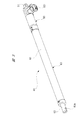
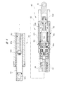
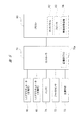
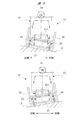
図1は本発明が適用された車椅子を前方側から見た斜視図を、図2(a)は図1の車椅子を側方から見た概略図、(b)は図1の車椅子を後方から見た概略図を、図3は図1の車椅子に設けたリニアアクチュエータの斜視図を、図4は図3のリニアアクチュエータの長手方向に沿う断面図を、図5は使用者により操作されるリモコンの正面図を、図6は図1の車椅子の電気系統を説明するブロック図を、図7(a),(b)は前後方向に傾斜した傾斜地でのリニアアクチュエータの動作説明図を、図8(a),(b)は左右方向に傾斜した傾斜地でのリニアアクチュエータの動作説明図をそれぞれ示している。 1 is a perspective view of a wheelchair to which the present invention is applied as viewed from the front side, FIG. 2A is a schematic view of the wheelchair of FIG. 1 as viewed from the side, and FIG. 3 is a perspective view of the linear actuator provided in the wheelchair of FIG. 1, FIG. 4 is a cross-sectional view of the linear actuator of FIG. 3, and FIG. 5 is a remote controller operated by the user. FIG. 6 is a block diagram for explaining the electrical system of the wheelchair of FIG. 1, FIGS. 7 (a) and 7 (b) are diagrams for explaining the operation of the linear actuator on an inclined ground inclined in the front-rear direction, and FIG. (A), (b) has each shown operation | movement explanatory drawing of the linear actuator in the inclined ground inclined in the left-right direction.
図1に示すように、移動支援装置としての車椅子10は、自力で移動するのが困難な使用者HM(図2参照)の移動を支援するものである。車椅子10は、台車20および支持部30を備えている。台車20は、車椅子10の左右側にそれぞれ対向配置され、略V字形状に形成された一対のフレーム部材21を備えている。これらのフレーム部材21は、それぞれ鋼管を溶接して所定形状に形成されている。
As shown in FIG. 1, a
一対のフレーム部材21の長手方向に沿う略中央部で、かつ一対のフレーム部材21の間には、鋼管よりなるセンターフレーム22が設けられている。センターフレーム22は、一対のフレーム部材21の略中央部分を所定間隔で支持し、かつその長手方向両端部で一対の駆動輪(車輪)23を回転自在に支持している。ここで、一対の駆動輪23には、使用者HMが操作するハンドリムHR(一方側のみを示す)がそれぞれ一体に設けられている。
A
また、一対のフレーム部材21の長手方向前方側で、かつ一対のフレーム部材21の間には、鋼管よりなるフロントフレーム24が設けられている。フロントフレーム24は、一対のフレーム部材21の前方側を所定間隔で支持している。そして、フロントフレーム24の長手方向両側で、かつ一対のフレーム部材21の長手方向前方側には、車椅子10の進行方向に向きを変えるキャスター(車輪)25がそれぞれ設けられている。
A
フロントフレーム24の長手方向に沿う略中央部には、鋼管よりなり、かつ座部31の前方側を支持する支持フレーム26が一体に設けられている。支持フレーム26は、フロントフレーム24の延在方向と直交する方向に延びており、その先端部分(図中上側)には、第1ボールジョイントBJ1が設けられている。ここで、第1ボールジョイントBJ1は、本発明におけるボールジョイントを構成しており、台車20の進行方向に沿う前方側で、かつ台車20の進行方向と交差する幅方向に沿う略中央部に配置されている。
A
これにより、支持部30(座部31)は、第1ボールジョイントBJ1を中心に、前後方向および左右方向に揺動自在となっている。すなわち、第1ボールジョイントBJ1は、台車20と支持部30との間に設けられ、台車20に対して支持部30を揺動自在に支持している。
Thereby, the support part 30 (seat part 31) is swingable in the front-rear direction and the left-right direction around the first ball joint BJ1. That is, the first ball joint BJ <b> 1 is provided between the
一対のフレーム部材21の長手方向後方側で、かつ一対のフレーム部材21の間には、鋼管よりなるリヤフレーム27が設けられている。リヤフレーム27は、一対のフレーム部材21の後方側を所定間隔で支持し、かつその長手方向両端部で一対の補助輪(車輪)28を回転自在に支持している。ここで、一対の補助輪28の直径寸法は、一対のキャスター25の直径寸法と略同じ直径寸法とされる。これにより、車椅子10の走行抵抗が増大するのを抑えている。
A
図1および図2に示すように、リヤフレーム27と座部31の後方側との間には、一対のリニアアクチュエータ(アクチュエータ)40が伸縮自在に設けられている。これらのリニアアクチュエータ40は、図2(b)に示すように、リヤフレーム27および座部31の駆動輪23寄りの部分にそれぞれ離れて配置され、一方のリニアアクチュエータ40は左側用とされ、他方のリニアアクチュエータ40は右側用とされている。つまり、一対のリニアアクチュエータ40は、台車20の進行方向に沿う後方側で、かつ台車20の進行方向と交差する幅方向に沿う左右側にそれぞれ設けられている。
As shown in FIGS. 1 and 2, a pair of linear actuators (actuators) 40 is provided between the
そして、一対のリニアアクチュエータ40の軸方向に沿うピストンチューブ62側(図2(a)中上側)が、第2ボールジョイントBJ2を介して座部31にそれぞれ揺動自在に装着されている。また、一対のリニアアクチュエータ40の軸方向に沿う送りねじ機構ケース61側(図2(a)中下側)が、第3ボールジョイントBJ3を介してリヤフレーム27にそれぞれ揺動自在に装着されている。これにより、一対のリニアアクチュエータ40を伸縮させることで、台車20に対して支持部30を揺動させることができる。
The
ここで、一対のリニアアクチュエータ40には、引き荷重タイプでは無く、押し荷重タイプのリニアアクチュエータを採用している。つまり、重量物を引っ張るためのリニアアクチュエータでは無く、重量物を押すためのリニアアクチュエータを採用している。したがって、一対のリニアアクチュエータ40は、常に押し荷重が掛かるような使い方をする必要がある。そこで、本実施の形態の車椅子10では、座部31の前方側を1つの支持フレーム26で支持し、座部31の後方側を一対の(2つの)リニアアクチュエータ40で支持している。これにより、一対のリニアアクチュエータ40には、使用者HMからの押し荷重が常に掛かることになり、支持部30を台車20に対してがたつくこと無く安定して支持することができる。
Here, the pair of
さらに、図2(a)に示すように、一対のリニアアクチュエータ40は、地面Gに対して、常にピストンチューブ62側が前方側に傾斜された状態となるように設置され、かつ図2(b)に示すように、一対のリニアアクチュエータ40は、互いに平行とならないように配置、具体的には略ハの字となるように配置されている。そして、一対のリニアアクチュエータ40は、車椅子10(台車20)をその進行方向から見たときに、互いに所定の相対角度α°(約15°)を持って並べられている。これにより、座部31の上で使用者HMの荷重移動があったとしても、一対のリニアアクチュエータ40には、引っ張り荷重が掛かり難くなっている。したがって、車椅子10には、十分な安定性が確保されている。
Further, as shown in FIG. 2A, the pair of
図1および図2に示すように、支持部30は、座部31、背もたれ部32およびレッグサポート33を備えており、使用者HMを支持するようになっている。座部31は、平面視で略正方形形状に形成され、使用者HMが腰掛けられるようになっている。座部31の前方側でかつ左右方向に沿う略中央部は、第1ボールジョイントBJ1を介して支持フレーム26により揺動自在に支持されている。また、座部31の後方側でかつその左右側は、それぞれ第2ボールジョイントBJ2を介してリニアアクチュエータ40により揺動自在に支持されている。
As shown in FIGS. 1 and 2, the
座部31の左右側には、使用者HMの衣類等が駆動輪23側にはみ出ないようにするためのガード34がそれぞれ設けられている。ガード34の上方側には、使用者HMの左右の腕AMを載置し得るアームレスト35がそれぞれ装着されている。これにより、座部31に腰掛けた使用者HMを、安定して支持することができる。
背もたれ部32は、座部31の後方側に一体に設けられ、座部31との相対角度は略100°となっている。これにより、使用者HMは、背もたれ部32に寄りかかり易くなっている。また、背もたれ部32は、平面視で略正方形形状に形成され、その座部31側とは反対側には、介護者等(図示せず)が把持して車椅子10の移動を補助するための一対のグリップGRが設けられている。なお、一対のグリップGRの近傍には、介護者等によって操作される補助ブレーキレバー(図示せず)が設けられている。
The
レッグサポート33は、使用者HMの左右の足FTに対応した2つのフットレスト33aを備えている。これらのフットレスト33aは、一対のキャスター25の前方側に配置されている。これにより、使用者HMは、一対のキャスター25に触れること無く、フットレスト33aに容易に足FTを乗せることができる。また、レッグサポート33は、レッグレスト33bを備えている。このレッグレスト33bは、フットレスト33aと座部31との間に配置され、使用者HMの足FTがフットレスト33aから滑り落ちるのを防止する。また、レッグレスト33bは、使用者HMのふくらはぎを支えるようになっている。
The
図3および図4に示すように、リニアアクチュエータ40は、駆動機構部50と、駆動機構部50により駆動される送りねじ機構部60とを同軸上に配置して略棒状に形成されている。送りねじ機構部60は、送りねじ機構ケース61に対して出入りするピストンチューブ62を備えており、駆動機構部50の駆動によりピストンチューブ62が送りねじ機構ケース61に対して相対移動(進退)される。
As shown in FIGS. 3 and 4, the
駆動機構部50には、第1固定部51が設けられ、第1固定部51には、第3ボールジョイントBJ3(図2参照)が取り付けられている。一方、ピストンチューブ62には、第2固定部62aが設けられ、第2固定部62aには、第2ボールジョイントBJ2(図2参照)が取り付けられている。つまり、リニアアクチュエータ40の駆動機構部50は、台車20(図1参照)寄りに配置されている。これにより、メカノイズを発生する駆動機構部50を座部31から遠ざけて、リニアアクチュエータ40の作動音を使用者HMに聞き取り難くさせて、静粛性を向上させている。
The
図4に示すように、駆動機構部50は、モータ部52と減速機構部53とを備えている。モータ部52は、筒状のモータケース52aを備えており、その径方向内側には永久磁石52bが固定されている。なお、永久磁石52bの配置関係を判り易くするために、永久磁石52bには網掛けを施している。
As shown in FIG. 4, the
永久磁石52bの径方向内側には、アーマチュア52cが回転自在に設けられている。また、アーマチュア52cの回転中心には、アーマチュア軸(回転軸)52dが貫通して固定されている。このように、モータケース52aの内部には、アーマチュア52cおよびアーマチュア軸52dが回転自在に収容されている。ここで、モータ部52は、複数のブラシ52eを備えたブラシ付きの電動モータとなっている。
An
なお、モータ部52としては、ブラシを備えないブラシレスの電動モータを採用することもできる。この場合、ブラシやコンミテータ(整流子)を備えない分、モータ部の軸長を短くすることができ、ひいてはリニアアクチュエータの作動ストロークを長くすることができる。また、ブラシを備えない分、電磁ノイズの発生やブラシ摺接音の発生等も無くすことができる。さらには、ブラシの摩耗粉が発生しないので電気系統の短絡故障を無くすことができ、かつブラシ交換等のメンテナンスを無くすこともできる。
The
図3に示すように、駆動機構部50の側方には、外部コネクタ(図示せず)が接続されるコネクタ接続部52fが設けられている。そして、外部コネクタからは、主操作部73およびリモコン80(図1参照)のうちの少なくとも何れか一方の操作に基づいて、背もたれ部32に固定されたバッテリ71(図1参照)から駆動電流が供給される。
As shown in FIG. 3, a
図4に示すように、アーマチュア軸52dの軸方向一端側(図中左側)は、減速機構部53の内部にまで延在されている。アーマチュア軸52dの軸方向一端側は、2段の遊星歯車減速機よりなる減速機構53aの入力側(図中右側)に連結されている。これにより、減速機構53aの径方向への大型化を抑えつつ、大きな減速比が得られるようにしている。よって、リニアアクチュエータ40の全体形状を、略段差の無いストレート形状にできる。そして、アーマチュア軸52dの回転は、減速機構53aによって減速されて高トルク化され、減速機構53aの出力側(図中左側)から送りねじ機構部60に向けて伝達される。
As shown in FIG. 4, one axial end side (left side in the figure) of the
送りねじ機構部60は、中空パイプよりなる送りねじ機構ケース61を備えており、送りねじ機構ケース61は、モータケース52aに対して同軸上に設けられている。図4に示すように、送りねじ機構ケース61の内部には、アーマチュア軸52dにより減速機構53aを介して回転されるシャフト63が回転自在に収容されている。
The feed
シャフト63の外周部分には、雄ねじ部63aが形成されており、雄ねじ部63aには、スクリューナット64がねじ結合されている。つまり、スクリューナット64は、シャフト63の回転に伴って、シャフト63の軸方向に移動するようになっている。具体的には、シャフト63を正転させると、スクリューナット64は図中右側に移動し、ひいてはリニアアクチュエータ40が縮小される。一方、シャフト63を逆転させると、スクリューナット64は図中左側に移動し、ひいてはリニアアクチュエータ40が伸張される。なお、スクリューナット64は、シャフト63の回転によって回転することは無く、スクリューナット64は、シャフト63の軸方向にのみ移動するようになっている。
A
スクリューナット64には、中空パイプよりなるピストンチューブ62の軸方向他端側が固定されている。ピストンチューブ62は、送りねじ機構ケース61とシャフト63との間に配置され、ピストンチューブ62は、送りねじ機構ケース61に対して出入り自在となっている。ここで、シャフト63,スクリューナット64およびピストンチューブ62によって、送りねじ機構を構成している。
The other end side in the axial direction of the
シャフト63の軸方向一端側には、ピストンチューブ62の内壁に摺接する環状の摺接部材63bが設けられている。摺接部材63bは、シャフト63と一緒にピストンチューブ62の内部で回転する。このように摺接部材63bを設けることで、ピストンチューブ62の軸心に対してシャフト63の軸心がずれないようにして、シャフト63の軸方向一端側の回転振れを抑制している。
An annular sliding
このように、リニアアクチュエータ40においては、モータ部52と、減速機構部53と、送りねじ機構部60とが、互いに同軸上に配置されている。したがって、リニアアクチュエータ40が略棒状に形成され、ひいては車椅子10の見栄えをすっきりさせることが可能となる。
Thus, in the
図1および図5に示すように、車椅子10は、コントローラ70を備えている。コントローラ70は、背もたれ部32に固定されたコントロールボックスBXの内部に収容されている。コントローラ70には、一対のリニアアクチュエータ40と、リニアアクチュエータ40を駆動するためのバッテリ71と、支持部30(座部31)の前後方向および左右方向への傾斜を検知するジャイロセンサ(傾斜センサ)72と、介護者等によって操作されるジョイスティック形状の主操作部73とが電気的に接続されている。ここで、バッテリ71およびジャイロセンサ72においても、コントロールボックスBXの内部に収容されている。
As shown in FIGS. 1 and 5, the
そして、コントローラ70は、自動運転時には、ジャイロセンサ72からの入力信号に基づいて、一対のリニアアクチュエータ40の長さを個別に制御して、支持部30を水平に保持する制御を実行する。これに対し、手動運転時には、介護者等による主操作部73の操作あるいは使用者HM(図2参照)によるリモコン80の操作に基づき、一対のリニアアクチュエータ40の長さが調整される。
And the
図1に示すように、リモコン(リモートコントロールユニット)80は、配線81を介してコントローラ70に電気的に接続されており、使用者HMにより操作可能となっている。なお、リモコン80を使用しない場合には、当該リモコン80は、ガード34に設けられたポケット34aにしまえるようになっている。
As shown in FIG. 1, a remote control (remote control unit) 80 is electrically connected to a
図5および図6に示すように、リモコン80は、使用者HMにより操作されるタッチパネル82を備えている。タッチパネル82には、傾斜表示部82aが設けられ、この傾斜表示部82aを目視することで、使用者HMは支持部30の傾斜具合を把握することができ、かつ支持部30を手動操作で水平状態にすることができる。ここで、傾斜表示部82aの表示内容は、ジャイロセンサ72からの入力信号に応じて、コントローラ70によって制御される。
As shown in FIGS. 5 and 6, the
また、タッチパネル82の傾斜表示部82aの近傍には、手動操作時に使用者HMにより操作される手動操作部82bが設けられている。手動操作部82bを操作することで、一対のリニアアクチュエータ40の長さが調整され、これにより支持部30を前後方向および左右方向に傾斜(揺動)させることができる。また、手動操作部82bの中央にある「切替」の部分をタッチすることで、コントローラ70による自動運転または使用者HMによる手動運転に切り替えることができる。なお、コントローラ70による自動運転に切り替えられると、コントローラ70は、ジャイロセンサ72からの入力信号に基づいて、一対のリニアアクチュエータ40の長さを個別に自動で制御し、ひいては支持部30が自動で水平状態に保持される。
A manual operation unit 82b that is operated by the user HM during manual operation is provided in the vicinity of the
さらに、タッチパネル82には、使用者情報表示部82cが設けられ、この使用者情報表示部82cには、使用者HMの体格情報が表示されるようになっている。具体的には、使用者HMの氏名,身長,体重が表示されるようになっている。これらの体格情報は、使用者情報表示部82cの近傍に設けられた入力部82dから入力される。なお、コントローラ70は、入力された体格情報に基づいて、支持部30の傾斜角度閾値(所定値)THを算出し、この傾斜角度閾値THをEEPROM等よりなる記憶部70aに記憶させる。そして、コントローラ70は、ジャイロセンサ72からの入力信号が示す現在の支持部30の傾斜角度(角度)と、記憶部70aに記憶された傾斜角度閾値THと、を比較する比較処理を実行するようになっている。
Further, the
ここで、使用者HMの体格情報は、一対のリニアアクチュエータ40の長さ調整に利用される。具体的には、例えば、背が高くかつ体重が重い使用者(A)と、背が低く体重が軽い使用者(B)とでは、使用者(A)の方が使用者(B)よりも重心が高くなる。言い換えれば、使用者HMの体格によって車椅子10の倒れ易さが変化することになる。そのため、コントローラ70は、車椅子10を倒れないようにするために、一対のリニアアクチュエータ40の長さ調整を、使用者HMの体格に応じて規制するようになっている。
Here, the physique information of the user HM is used for length adjustment of the pair of
より具体的には、重心が高い使用者(A)の場合には、支持部30を大きく傾斜させないようにするために、傾斜角度閾値THは小さめの角度に設定され、一対のリニアアクチュエータ40の長さ調整範囲が狭くなる。これに対し、使用者(A)よりも重心が低い使用者(B)の場合には、上述とは逆に、傾斜角度閾値THは大きめの角度に設定され、一対のリニアアクチュエータ40の長さ調整範囲が広くなる。
More specifically, in the case of a user (A) having a high center of gravity, the inclination angle threshold value TH is set to a small angle so that the
これにより、コントローラ70は、自動運転時において、使用者HMの体格に応じた支持部30の最適な角度調整制御を行うことができる。なお、手動運転時には、ジャイロセンサ72からの入力信号が示す現在の支持部30の傾斜角度が、傾斜角度閾値TH以上となると、一対のリニアアクチュエータ40の動作がコントローラ70によって強制停止され、支持部30の傾斜角度がそれ以上の大きさにならないようにする。
Thereby, the
また、リモコン80にはスピーカ83が設けられている。そして、コントローラ70は、ジャイロセンサ72からの入力信号が示す現在の支持部30の傾斜角度が、傾斜角度閾値TH以上となると、車椅子10が転倒する虞があるとして、スピーカ83から周囲に警報音を発音させる。これにより、車椅子10の周囲にいる健常者等が、車椅子10の異常に気付くことができる。ここで、警報音としては、断続的に鳴る電子音でも良いし、音声によるアナウンスでも構わない。
The
さらに、リモコン80には無線送信機84が設けられている。この無線送信機84は、無線LAN等の無線通信手段を介して、車椅子10を管理する管理者(老人ホームなどの施設の責任者等)の携帯端末等と通信可能となっている。そして、コントローラ70は、ジャイロセンサ72からの入力信号が示す現在の支持部30の傾斜角度が、傾斜角度閾値TH以上となると、車椅子10が転倒する虞があるとして、無線送信機84を作動させる。これにより、管理者は、車椅子10の異常を、携帯端末等を介して知ることができる。
Further, the
このように、コントローラ70は、車椅子10が転倒しそうになると、周囲に警報音を発音するとともに管理者にも通報するので、車椅子10を使用者HMが単独で使用していたとしても、車椅子10が転倒しそうなことを周囲の健常者等が直ぐに気付くことができる。よって、車椅子10の転倒を未然に防ぐことができるとともに、健常者等により車椅子10を安全な状態にすることができる。
Thus, when the
次に、以上のように形成した車椅子10の動作、特に、一対のリニアアクチュエータ40の動作について、図面を用いて詳細に説明する。
Next, the operation of the
[前後方向傾斜制御]
自動運転時において、コントローラ70は、図7(a)に示すように、車椅子10の進行方向(前方側)が登り坂のときには、ジャイロセンサ72による地面Gの傾斜検知に基づき、一対のリニアアクチュエータ40を同期して伸張動作させる。これにより、支持部30が台車20に対して第1ボールジョイントBJ1を中心に揺動して前傾姿勢となり、ひいては支持部30が水平状態とされる。
[Front / back direction tilt control]
At the time of automatic driving, as shown in FIG. 7A, the
一方、図7(b)に示すように、車椅子10の進行方向(前方側)が下り坂のときには、コントローラ70は、ジャイロセンサ72による地面Gの傾斜検知に基づき、一対のリニアアクチュエータ40を同期して縮小動作させる。これにより、支持部30が台車20に対して第1ボールジョイントBJ1を中心に揺動して後傾姿勢となり、ひいては支持部30が水平状態とされる。
On the other hand, as shown in FIG. 7B, when the traveling direction (front side) of the
これにより、使用者HMは、座部31上でバランスを崩すことなく、不安感を抱くこと無く腰掛けることができる。
Accordingly, the user HM can sit on the
[左右方向傾斜制御]
自動運転時において、コントローラ70は、図8(a)に示すように、車椅子10の右側が下がった状態になると、ジャイロセンサ72による地面Gの傾斜検知に基づき、一対のリニアアクチュエータ40のうち、右側用を伸張動作させ、左側用を縮小動作させる。これにより、支持部30が台車20に対して第1ボールジョイントBJ1を中心に揺動して左側が下がった姿勢となって、ひいては支持部30が水平状態とされる。
[Horizontal tilt control]
At the time of automatic driving, as shown in FIG. 8A, when the right side of the
一方、図8(b)に示すように、車椅子10の左側が下がった状態になると、コントローラ70は、ジャイロセンサ72による地面Gの傾斜検知に基づき、一対のリニアアクチュエータ40のうち、左側用を伸張動作させ、右側用を縮小動作させる。これにより、支持部30が台車20に対して第1ボールジョイントBJ1を中心に揺動して右側が下がった姿勢となって、ひいては支持部30が水平状態とされる。
On the other hand, as shown in FIG. 8B, when the left side of the
これにより、使用者HMは、座部31上でバランスを崩すことなく、不安感を抱くこと無く腰掛けることができる。
Accordingly, the user HM can sit on the
なお、前後方向の傾斜と左右方向の傾斜とが複合したような傾斜の地面Gの場合、例えば、車椅子10の進行方向右斜め前方が登り坂であるような場合であっても、ジャイロセンサ72による地面Gの傾斜検知に基づき、一対のリニアアクチュエータ40の長さがそれぞれ個別に制御され、ひいては支持部30が水平状態とされる。
Note that in the case of the ground G having an inclination in which the inclination in the front-rear direction and the inclination in the left-right direction are combined, for example, the
以上詳述したように、本実施の形態によれば、台車20に対して支持部30を揺動自在に支持する第1ボールジョイントBJ1と、台車20と支持部30との間に伸縮自在に設けられ、台車20に対して支持部30を揺動させる一対のリニアアクチュエータ40と、を有するので、第1ボールジョイントBJ1を中心として、台車20に対して支持部30を種々の方向に揺動させることができる。これにより、進行方向左側が下がるような傾斜地や、進行方向前方が下がる傾斜地等においても、台車20に対して支持部30を揺動させて、当該支持部30を水平に保持することができる。したがって、使用者HMへの負担を軽減できるのは勿論のこと、介護者等への負担も軽減することが可能となる。
As described above in detail, according to the present embodiment, the first ball joint BJ1 that supports the
また、本実施の形態によれば、第1ボールジョイントBJ1が、台車20の進行方向に沿う前方側で、かつ台車20の進行方向と交差する幅方向に沿う中央部に設けられ、一対のリニアアクチュエータ40が、台車20の進行方向に沿う後方側で、かつ台車20の進行方向と交差する幅方向に沿う左右側にそれぞれ設けられている。これにより、一対のリニアアクチュエータ40に、使用者HMからの押し荷重を常に掛けることができ、ひいては比較的安価な押し荷重タイプのリニアアクチュエータを採用することが可能となる。
Moreover, according to this Embodiment, 1st ball joint BJ1 is provided in the center part along the width direction which cross | intersects the advancing direction of the trolley |
さらに、本実施の形態によれば、一対のリニアアクチュエータ40が、台車20をその進行方向から見たときに、互いに所定の相対角度を持って並べられているので、座部31の上で使用者HMの荷重移動があったとしても、一対のリニアアクチュエータ40には、引っ張り荷重が掛かり難くなっている。したがって、比較的安価な押し荷重タイプのリニアアクチュエータを採用しつつ、車椅子10の安定性を向上させることができる。
Furthermore, according to the present embodiment, the pair of
また、本実施の形態によれば、リニアアクチュエータ40は、アーマチュア軸52dを有するモータ部52と、アーマチュア軸52dの回転を減速して出力する減速機構部53と、減速機構部53の出力が伝達される送りねじ機構部60と、を備え、モータ部52、減速機構部53および送りねじ機構部60を、互いに同軸上に配置している。これにより、リニアアクチュエータ40を略棒状に形成することができ、ひいては車椅子10の見栄えをすっきりさせることが可能となる。
Further, according to the present embodiment, the
さらに、本実施の形態によれば、一対のリニアアクチュエータ40の長さを個別に制御するコントローラ70と、支持部30の前後方向および左右方向への傾斜を検知するジャイロセンサ72と、を備え、コントローラ70は、ジャイロセンサ72からの入力信号に基づいて、一対のリニアアクチュエータ40を個別に制御する。したがって、車椅子10が種々の傾斜した地面Gを走行する場合であっても、支持部30は自動で水平に保持される。よって、使用者HMは不安感を抱くことが無い。
Furthermore, according to the present embodiment, the
また、本実施の形態によれば、コントローラ70は、ジャイロセンサ72からの入力信号が示す角度が傾斜角度閾値TH以上になると、スピーカ83から周囲に警報音を発音したり、無線送信機84を介して管理者に通報したりする。これにより、車椅子10を使用者HMが単独で使用していたとしても、車椅子10が転倒しそうなことを周囲の健常者等が直ぐに気付くことができる。よって、車椅子10の転倒を未然に防ぐことができ、より安全性を向上させることができる。
Further, according to the present embodiment, when the angle indicated by the input signal from the
さらに、本実施の形態によれば、コントローラ70は、使用者HMの体格情報に基づいて、傾斜角度閾値THを設定するので、体格の異なる種々の使用者HMに対応することが可能となる。
Furthermore, according to the present embodiment, the
本発明は上記実施の形態に限定されるものではなく、その要旨を逸脱しない範囲で種々変更可能であることは言うまでもない。例えば、上記実施の形態では、第1ボールジョイントBJ1を、台車20の進行方向に沿う前方側で、かつ台車20の進行方向と交差する幅方向に沿う中央部に設け、一対のリニアアクチュエータ40を、台車20の進行方向に沿う後方側で、かつ台車20の進行方向と交差する幅方向に沿う左右側にそれぞれ設けたが、本発明はこれに限らない。上記実施の形態とは逆に、第1ボールジョイントBJ1を、台車20の進行方向に沿う後方側で、かつ台車20の進行方向と交差する幅方向に沿う中央部に設け、一対のリニアアクチュエータ40を、台車20の進行方向に沿う前方側で、かつ台車20の進行方向と交差する幅方向に沿う左右側にそれぞれ設けることもできる。
It goes without saying that the present invention is not limited to the above-described embodiment, and various modifications can be made without departing from the scope of the invention. For example, in the above embodiment, the first ball joint BJ1 is provided on the front side along the traveling direction of the
また、上記実施の形態では、移動支援装置として、車椅子10であるものを示したが、本発明はこれに限らず、移動支援装置としての複数のキャスター(車輪)を備えたストレッチャーにも適用することができる。
Moreover, in the said embodiment, although what was the
さらに、一対のリニアアクチュエータ40を制御して、車椅子10の座部31の後方側を積極的に持ち上げることで、使用者HMを前傾姿勢にすることができる。そのため、上記実施の形態のように座部31を水平に保持するに限らず、例えば、使用者HMが机などで作業をする場合に、一対のリニアアクチュエータ40を制御して使用者HMを前傾姿勢とすることで、使用者HMを机に接近させることができる。よって、使用者HMは、机での作業(食事や書き物等)を容易に行えるようになる。また、座部31の後方側をさらに持ち上げるようにすれば、車椅子10によって使用者HMの立ち上がりを補助することができる。
Furthermore, by controlling the pair of
その他、上記実施の形態における各構成要素の材質,形状,寸法,数,設置箇所等は、本発明を達成できるものであれば任意であって、上記実施の形態に限定されるものではない。 In addition, the material, shape, dimension, number, installation location, and the like of each component in the above embodiment are arbitrary as long as the present invention can be achieved, and are not limited to the above embodiment.
10 車椅子(移動支援装置)
20 台車
21 フレーム部材
22 センターフレーム
23 駆動輪(車輪)
24 フロントフレーム
25 キャスター(車輪)
26 支持フレーム
27 リヤフレーム
28 補助輪(車輪)
30 支持部
31 座部
32 背もたれ部
33 レッグサポート
33a フットレスト
33b レッグレスト
34 ガード
34a ポケット
35 アームレスト
40 リニアアクチュエータ(アクチュエータ)
50 駆動機構部
51 第1固定部
52 モータ部
52a モータケース
52b 永久磁石
52c アーマチュア
52d アーマチュア軸(回転軸)
52e ブラシ
52f コネクタ接続部
53 減速機構部
53a 減速機構
60 送りねじ機構部
61 送りねじ機構ケース
62 ピストンチューブ
62a 第2固定部
63 シャフト
63a 雄ねじ部
63b 摺接部材
64 スクリューナット
70 コントローラ
70a 記憶部
71 バッテリ
72 ジャイロセンサ(傾斜センサ)
73 主操作部
80 リモコン
81 配線
82 タッチパネル
82a 傾斜表示部
82b 手動操作部
82c 使用者情報表示部
82d 入力部
83 スピーカ
84 無線送信機
AM 腕
BJ1 第1ボールジョイント(ボールジョイント)
BJ2 第2ボールジョイント
BJ3 第3ボールジョイント
BX コントロールボックス
FT 足
G 地面
GR グリップ
HM 使用者
HR ハンドリム
TH 傾斜角度閾値
10 Wheelchair (movement support device)
20
24
26
DESCRIPTION OF
DESCRIPTION OF
73
BJ2 2nd ball joint BJ3 3rd ball joint BX Control box FT Foot G Ground GR grip HM User HR Hand rim TH Tilt angle threshold
Claims (8)
複数の車輪を備えた台車と、
前記使用者を支持する支持部と、
前記台車と前記支持部との間に設けられ、前記台車に対して前記支持部を揺動自在に支持するボールジョイントと、
前記台車と前記支持部との間に伸縮自在に設けられ、前記台車に対して前記支持部を揺動させる一対のアクチュエータと、
を有する、移動支援装置。 A movement support device for supporting the movement of a user,
A carriage with multiple wheels;
A support part for supporting the user;
A ball joint which is provided between the carriage and the support part and supports the support part in a swingable manner with respect to the carriage;
A pair of actuators provided between the carriage and the support portion so as to be extendable and contractable to swing the support portion with respect to the carriage;
A movement support apparatus.
前記ボールジョイントが、前記台車の進行方向に沿う前方側または後方側のいずれか一方で、かつ前記台車の進行方向と交差する幅方向に沿う中央部に設けられ、
前記一対のアクチュエータが、前記台車の進行方向に沿う前方側または後方側のいずれか他方で、かつ前記台車の進行方向と交差する幅方向に沿う左右側にそれぞれ設けられている、
移動支援装置。 The movement support apparatus according to claim 1,
The ball joint is provided at either the front side or the rear side along the traveling direction of the carriage, and at the center along the width direction intersecting the traveling direction of the carriage,
The pair of actuators is provided on either the front side or the rear side along the traveling direction of the carriage, and on the left and right sides along the width direction intersecting with the traveling direction of the carriage,
Mobility support device.
前記一対のアクチュエータが、前記台車をその進行方向から見たときに、互いに所定の相対角度を持って並べられている、
移動支援装置。 In the movement assistance apparatus of Claim 1 or 2,
The pair of actuators are arranged with a predetermined relative angle to each other when the cart is viewed from its traveling direction.
Mobility support device.
前記アクチュエータは、
回転軸を有するモータ部と、
前記回転軸の回転を減速して出力する減速機構部と、
前記減速機構部の出力が伝達される送りねじ機構部と、
を備え、
前記モータ部、前記減速機構部および前記送りねじ機構部が、互いに同軸上に配置されている、
移動支援装置。 In the movement assistance apparatus of any one of Claims 1-3,
The actuator is
A motor unit having a rotating shaft;
A speed reduction mechanism that decelerates and outputs the rotation of the rotary shaft;
A feed screw mechanism that transmits the output of the speed reduction mechanism;
With
The motor part, the speed reduction mechanism part and the feed screw mechanism part are arranged coaxially with each other,
Mobility support device.
前記一対のアクチュエータの長さを個別に制御するコントローラと、
前記支持部の前後方向および左右方向への傾斜を検知する傾斜センサと、
を備え、
前記コントローラは、前記傾斜センサからの入力信号に基づいて、前記一対のアクチュエータを個別に制御する、
移動支援装置。 In the movement assistance apparatus of any one of Claims 1-4,
A controller for individually controlling the length of the pair of actuators;
A tilt sensor for detecting the tilt of the support portion in the front-rear direction and the left-right direction;
With
The controller individually controls the pair of actuators based on an input signal from the tilt sensor.
Mobility support device.
前記コントローラは、前記傾斜センサからの入力信号が示す角度が所定値以上になると、スピーカから警報音を発音させる、
移動支援装置。 The movement support apparatus according to claim 5,
When the angle indicated by the input signal from the tilt sensor is equal to or greater than a predetermined value, the controller sounds an alarm sound from a speaker.
Mobility support device.
前記コントローラは、前記傾斜センサからの入力信号が示す角度が所定値以上になると、無線送信機を作動させる、
移動支援装置。 In the movement assistance apparatus of Claim 5 or 6,
The controller activates a wireless transmitter when an angle indicated by an input signal from the tilt sensor is equal to or greater than a predetermined value.
Mobility support device.
前記コントローラは、前記使用者の体格情報に基づいて、前記所定値を設定する、
移動支援装置。 The movement support apparatus according to claim 6 or 7,
The controller sets the predetermined value based on the physique information of the user,
Mobility support device.
Priority Applications (1)
| Application Number | Priority Date | Filing Date | Title |
|---|---|---|---|
| JP2016055420A JP2017164431A (en) | 2016-03-18 | 2016-03-18 | Movement support device |
Applications Claiming Priority (1)
| Application Number | Priority Date | Filing Date | Title |
|---|---|---|---|
| JP2016055420A JP2017164431A (en) | 2016-03-18 | 2016-03-18 | Movement support device |
Publications (1)
| Publication Number | Publication Date |
|---|---|
| JP2017164431A true JP2017164431A (en) | 2017-09-21 |
Family
ID=59910353
Family Applications (1)
| Application Number | Title | Priority Date | Filing Date |
|---|---|---|---|
| JP2016055420A Pending JP2017164431A (en) | 2016-03-18 | 2016-03-18 | Movement support device |
Country Status (1)
| Country | Link |
|---|---|
| JP (1) | JP2017164431A (en) |
Cited By (4)
| Publication number | Priority date | Publication date | Assignee | Title |
|---|---|---|---|---|
| KR20200037610A (en) * | 2018-10-01 | 2020-04-09 | 순천향대학교 산학협력단 | Wheel Chair Having Horizontal Maintenance Function |
| CN110979504A (en) * | 2019-12-30 | 2020-04-10 | 杭州义顺科技有限公司 | Posture self-adaptive walking-aid robot |
| NO20190030A1 (en) * | 2019-01-09 | 2020-07-10 | Hallvard Dahle | Self-leveling wheelchair |
| JP7498103B2 (en) | 2020-12-16 | 2024-06-11 | 株式会社Soken | Electric wheelchair |
Citations (6)
| Publication number | Priority date | Publication date | Assignee | Title |
|---|---|---|---|---|
| JPH06286507A (en) * | 1993-03-30 | 1994-10-11 | Isuzu Motors Ltd | Attitude control device for seat |
| US6068280A (en) * | 1996-09-13 | 2000-05-30 | Torres; Hank G. | Self-leveling seat for a wheelchair |
| JP2007186184A (en) * | 2005-12-14 | 2007-07-26 | Equos Research Co Ltd | Vehicle |
| JP2010263670A (en) * | 2009-04-30 | 2010-11-18 | Mitsuba Corp | Linear actuator |
| JP2015024015A (en) * | 2013-07-26 | 2015-02-05 | アイシン精機株式会社 | Electric wheelchair |
| US9073399B1 (en) * | 2014-10-10 | 2015-07-07 | Max Mobility, Llc | System and method for adjusting a wheelchair seat |
-
2016
- 2016-03-18 JP JP2016055420A patent/JP2017164431A/en active Pending
Patent Citations (6)
| Publication number | Priority date | Publication date | Assignee | Title |
|---|---|---|---|---|
| JPH06286507A (en) * | 1993-03-30 | 1994-10-11 | Isuzu Motors Ltd | Attitude control device for seat |
| US6068280A (en) * | 1996-09-13 | 2000-05-30 | Torres; Hank G. | Self-leveling seat for a wheelchair |
| JP2007186184A (en) * | 2005-12-14 | 2007-07-26 | Equos Research Co Ltd | Vehicle |
| JP2010263670A (en) * | 2009-04-30 | 2010-11-18 | Mitsuba Corp | Linear actuator |
| JP2015024015A (en) * | 2013-07-26 | 2015-02-05 | アイシン精機株式会社 | Electric wheelchair |
| US9073399B1 (en) * | 2014-10-10 | 2015-07-07 | Max Mobility, Llc | System and method for adjusting a wheelchair seat |
Cited By (6)
| Publication number | Priority date | Publication date | Assignee | Title |
|---|---|---|---|---|
| KR20200037610A (en) * | 2018-10-01 | 2020-04-09 | 순천향대학교 산학협력단 | Wheel Chair Having Horizontal Maintenance Function |
| KR102186898B1 (en) * | 2018-10-01 | 2020-12-04 | 순천향대학교 산학협력단 | Wheel Chair Having Horizontal Maintenance Function |
| NO20190030A1 (en) * | 2019-01-09 | 2020-07-10 | Hallvard Dahle | Self-leveling wheelchair |
| NO345178B1 (en) * | 2019-01-09 | 2020-10-26 | Hallvard Dahle | Self-leveling wheelchair |
| CN110979504A (en) * | 2019-12-30 | 2020-04-10 | 杭州义顺科技有限公司 | Posture self-adaptive walking-aid robot |
| JP7498103B2 (en) | 2020-12-16 | 2024-06-11 | 株式会社Soken | Electric wheelchair |
Similar Documents
| Publication | Publication Date | Title |
|---|---|---|
| US8522907B1 (en) | Personal mobility device | |
| JP5911559B2 (en) | Mobile device for the handicapped | |
| JP2017164431A (en) | Movement support device | |
| US20160270988A1 (en) | Modularized mobility device | |
| JP2013530740A (en) | Mobility support equipment | |
| JP2017070352A (en) | Movement support device | |
| JP2014079364A (en) | Walking training aid | |
| KR20130139470A (en) | Powered wheel rider having multi-functions | |
| JP5802415B2 (en) | Indoor mobility equipment and safety equipment for casters | |
| EP3072489A1 (en) | Multifunctional transport and rehabilitation robot | |
| KR101536932B1 (en) | Apparatus capable of standing up and moving | |
| KR101517292B1 (en) | Walking assistant robot | |
| KR20130117602A (en) | Folding electric walking aid vehicle | |
| US20160008207A1 (en) | Care support apparatus | |
| KR20190065612A (en) | Walking assistance device for help standing and sitting moving if user | |
| KR20120096118A (en) | Passivity and electro motion wheelchairs | |
| JP2015002879A (en) | Walker | |
| JP3182010U (en) | Mobility aid | |
| KR101393452B1 (en) | Boarding mobile apparatus for maintaining posture balance | |
| KR101216028B1 (en) | The application of balancing two-wheeled driving robot features a wheelchair | |
| KR101772509B1 (en) | electric wheelchair having easy-steering and no-central axis | |
| JP2016116823A (en) | Three-wheeled chair | |
| KR101283373B1 (en) | Walker | |
| KR102624268B1 (en) | Electric wheelchair-attachable apparatus for low-limb muscular exercise | |
| TWM572735U (en) | Electric mobile aid |
Legal Events
| Date | Code | Title | Description |
|---|---|---|---|
| A621 | Written request for application examination |
Free format text: JAPANESE INTERMEDIATE CODE: A621 Effective date: 20180921 |
|
| A977 | Report on retrieval |
Free format text: JAPANESE INTERMEDIATE CODE: A971007 Effective date: 20190816 |
|
| A131 | Notification of reasons for refusal |
Free format text: JAPANESE INTERMEDIATE CODE: A131 Effective date: 20190827 |
|
| A02 | Decision of refusal |
Free format text: JAPANESE INTERMEDIATE CODE: A02 Effective date: 20200324 |