JP2017159774A - Pneumatic tire - Google Patents
Pneumatic tire Download PDFInfo
- Publication number
- JP2017159774A JP2017159774A JP2016045508A JP2016045508A JP2017159774A JP 2017159774 A JP2017159774 A JP 2017159774A JP 2016045508 A JP2016045508 A JP 2016045508A JP 2016045508 A JP2016045508 A JP 2016045508A JP 2017159774 A JP2017159774 A JP 2017159774A
- Authority
- JP
- Japan
- Prior art keywords
- tire
- strip
- elastic modulus
- belt
- tread
- Prior art date
- Legal status (The legal status is an assumption and is not a legal conclusion. Google has not performed a legal analysis and makes no representation as to the accuracy of the status listed.)
- Pending
Links
Images


Landscapes
- Tires In General (AREA)
Abstract
Description
本発明は、空気入りタイヤに関する。 The present invention relates to a pneumatic tire.
雨天時での走行が考慮され、タイヤのトレッドには通常、周方向に延在する溝(以下、主溝と称される。)が刻まれている。雨天時においてタイヤと路面との間に存在する水は、この主溝を通じて排出される。 Considering running in rainy weather, a tire tread is usually engraved with a groove extending in the circumferential direction (hereinafter referred to as a main groove). Water that is present between the tire and the road surface in the rain is discharged through this main groove.
タイヤが路面と接触すると、主溝と路面とによって囲まれた空間が形成される。この空間内には、気体(具体的には、空気)が存在する。走行状態では、この空気が振動し、800Hzから1kHz帯域のノイズ(以下、高周波ノイズ)が発生してしまう。この高周波ノイズは、気柱共鳴音とも称される。気柱共鳴音は、タイヤの通過騒音に影響する。 When the tire contacts the road surface, a space surrounded by the main groove and the road surface is formed. Gas (specifically, air) exists in this space. In the running state, this air vibrates and noise in the 800 Hz to 1 kHz band (hereinafter referred to as high frequency noise) is generated. This high frequency noise is also referred to as air column resonance. The air column resonance affects the passing noise of the tire.
静粛性の観点から、気柱共鳴音の低減に関し、様々な検討が行われている。この検討の一例が、特開2005−035345公報に開示されている。 From the viewpoint of quietness, various studies have been conducted on the reduction of air column resonance. An example of this study is disclosed in Japanese Patent Application Laid-Open No. 2005-035345.
主溝の容積は、気柱共鳴音に影響する。小さな容積を有する主溝は、通過騒音の低減に寄与する。しかし、気柱共鳴音の低減のために主溝の容積を低減すると、排水性が低下し、ウェットグリップ性能が損なわれる恐れがある。 The volume of the main groove affects the air column resonance sound. The main groove having a small volume contributes to a reduction in passing noise. However, if the volume of the main groove is reduced in order to reduce air column resonance, the drainage performance is lowered and the wet grip performance may be impaired.
上記公報に記載のタイヤでは、主溝の半径方向内側に、この主溝に沿って延在する補強層が設けられている。この補強層を、トレッド部を形成するゴムの幅方向剛性よりも、大きな幅方向剛性を有するゴムで形成することで、このトレッド部の幅方向の剛性をほぼ均一にし、高周波ノイズの低減が図られている。 In the tire described in the above publication, a reinforcing layer extending along the main groove is provided on the radially inner side of the main groove. By forming this reinforcing layer with rubber having a rigidity in the width direction that is greater than the rigidity in the width direction of the rubber that forms the tread portion, the rigidity in the width direction of the tread portion is made substantially uniform, thereby reducing high-frequency noise. It has been.
ところで前述の、補強層のためのゴムは、幅方向の剛性を確保するために、例えば、周方向に対して90°傾けられた、すなわち実質的に軸方向に延在する、コードを含んでいる。軸方向に延在する多数のコードを周方向に並列させた部品の製造には、多数のステップが必要である。このため、この補強層の採用は、タイヤの生産性を損なう恐れがある。 By the way, the rubber for the reinforcing layer described above includes, for example, a cord that is inclined by 90 ° with respect to the circumferential direction, that is, substantially extends in the axial direction, in order to ensure rigidity in the width direction. Yes. Many steps are required to manufacture a part in which a large number of cords extending in the axial direction are arranged in the circumferential direction. For this reason, the use of this reinforcing layer may impair the productivity of the tire.
高周波ノイズ、言い換えれば、気柱共鳴音の低減のための技術に関しては、改善の余地が残されているのが実情である。 As for the technology for reducing high-frequency noise, in other words, air column resonance, there is still room for improvement.
本発明の目的は、生産性への影響を抑えつつ、気柱共鳴音の低減が達成された空気入りタイヤの提供にある。 An object of the present invention is to provide a pneumatic tire in which the reduction of air column resonance noise is achieved while suppressing the influence on productivity.
本発明に係る空気入りタイヤは、トレッド、ベルト及びストリップを備えている。上記ベルトは、上記トレッドの半径方向内側に位置している。このベルトは、並列された多数のコードを含んでいる。それぞれのコードは、赤道面に対して傾斜している。上記トレッドは、周方向に延在する溝を備えている。上記ストリップは、半径方向において、上記溝と上記ベルトとの間に位置している。上記ストリップは、上記ベルトの幅よりも小さな幅を有している。上記トレッドの周方向の弾性率に対する上記ストリップの周方向の弾性率の比は、2以上である。 The pneumatic tire according to the present invention includes a tread, a belt, and a strip. The belt is located on the radially inner side of the tread. This belt contains a number of cords in parallel. Each cord is inclined with respect to the equator plane. The tread includes a groove extending in the circumferential direction. The strip is located between the groove and the belt in the radial direction. The strip has a width smaller than the width of the belt. The ratio of the elastic modulus in the circumferential direction of the strip to the elastic modulus in the circumferential direction of the tread is 2 or more.
好ましくは、この空気入りタイヤでは、上記溝の底の幅に対する上記ストリップの幅の比は3以下である。 Preferably, in this pneumatic tire, the ratio of the width of the strip to the width of the bottom of the groove is 3 or less.
好ましくは、この空気入りタイヤでは、上記ストリップの半径方向の弾性率はこのストリップの周方向の弾性率よりも小さい。より好ましくは、上記ストリップの周方向の弾性率に対するこのストリップの半径方向の弾性率の比は0.9以下である。 Preferably, in this pneumatic tire, the elastic modulus in the radial direction of the strip is smaller than the elastic modulus in the circumferential direction of the strip. More preferably, the ratio of the elastic modulus in the radial direction of the strip to the elastic modulus in the circumferential direction of the strip is 0.9 or less.
本発明に係る空気入りタイヤでは、溝の半径方向内側に、周方向の剛性が高いストリップが設けられている。このストリップは、溝の底の部分の剛性、詳細には、この部分の周方向の剛性に寄与する。溝の底の部分の剛性が高いので、このタイヤでは、この底の部分の振動が効果的に抑制される。 In the pneumatic tire according to the present invention, a strip having high circumferential rigidity is provided on the radially inner side of the groove. This strip contributes to the rigidity of the bottom part of the groove, in particular the circumferential rigidity of this part. Since the rigidity of the bottom portion of the groove is high, the vibration of the bottom portion is effectively suppressed in this tire.
このタイヤでは、トレッドの内側にベルトが設けられている。発明者らは、詳細な検討により、軸方向の振動の減衰にベルトが効果的に寄与するという知見を得ている。つまりこのタイヤでは、このベルトによる振動の減衰効果もあって、つまり、ストリップとベルトとの相乗的な作用により、溝の底の部分の振動がかなり抑制される。振動の抑制は、小さな加振力を招来する。 In this tire, a belt is provided inside the tread. The inventors have obtained the knowledge that the belt effectively contributes to the attenuation of the vibration in the axial direction through detailed examination. That is, this tire also has a vibration damping effect by the belt, that is, the vibration of the bottom portion of the groove is considerably suppressed by the synergistic action of the strip and the belt. Suppression of vibration invites a small excitation force.
このタイヤでは、加振力が小さくなる、すなわち、気柱共鳴音が低減される。しかもこの気柱共鳴音の低減のために、従来タイヤのように、軸方向の剛性確保のための部材を要しない。本発明によれば、生産性への影響を抑えつつ、気柱共鳴音の低減が達成された空気入りタイヤが得られる。 In this tire, the excitation force is reduced, that is, the air column resonance noise is reduced. Moreover, in order to reduce the air column resonance noise, a member for securing axial rigidity is not required unlike the conventional tire. ADVANTAGE OF THE INVENTION According to this invention, the pneumatic tire by which reduction of the air column resonance sound was achieved was suppressed, suppressing the influence on productivity.
以下、適宜図面が参照されつつ、好ましい実施形態に基づいて本発明が詳細に説明される。 Hereinafter, the present invention will be described in detail based on preferred embodiments with appropriate reference to the drawings.
図1には、空気入りタイヤ2が示されている。図1において、上下方向がタイヤ2の半径方向であり、左右方向がタイヤ2の軸方向であり、紙面との垂直方向がタイヤ2の周方向である。図1において、一点鎖線CLはタイヤ2の赤道面を表わす。このタイヤ2の形状は、トレッドパターンを除き、赤道面に対して対称である。
FIG. 1 shows a
図1において、タイヤ2はリムRに組み込まれている。このリムRは、正規リムである。このタイヤ2には、正規内圧となるように空気が充填されている。
In FIG. 1, a
本発明では、タイヤ2の各部材の寸法及び角度は、特に言及がない限り、タイヤ2が正規リムに組み込まれ、正規内圧となるようにタイヤ2に空気が充填された状態で測定される。測定時には、タイヤ2には荷重がかけられない。タイヤ2が乗用車用である場合は、特に言及がない限り、内圧が180kPaの状態で、寸法及び角度が測定される。
In the present invention, the dimension and angle of each member of the
本明細書において正規リムとは、タイヤ2が依拠する規格において定められたリムを意味する。JATMA規格における「標準リム」、TRA規格における「Design Rim」、及びETRTO規格における「Measuring Rim」は、正規リムである。
In the present specification, the normal rim means a rim defined in a standard on which the
本明細書において正規内圧とは、タイヤ2が依拠する規格において定められた内圧を意味する。JATMA規格における「最高空気圧」、TRA規格における「TIRE LOAD LIMITS AT VARIOUS COLD INFLATION PRESSURES」に掲載された「最大値」、及びETRTO規格における「INFLATION PRESSURE」は、正規内圧である。
In the present specification, the normal internal pressure means an internal pressure defined in a standard on which the
本明細書において正規荷重とは、タイヤ2が依拠する規格において定められた荷重を意味する。JATMA規格における「最高負荷能力」、TRA規格における「TIRE LOAD LIMITS AT VARIOUS COLD INFLATION PRESSURES」に掲載された「最大値」、及びETRTO規格における「LOAD CAPACITY」は、正規荷重である。
In the present specification, the normal load means a load defined in a standard on which the
このタイヤ2は、トレッド4、一対のサイドウォール6、一対のウィング8、一対のクリンチ10、一対のビード12、カーカス14、ベルト16、バンド18、インナーライナー20及び一対のチェーファー22を備えている。このタイヤ2は、チューブレスタイプである。このタイヤ2は、乗用車に装着される。
The
トレッド4は、半径方向外向きに凸な形状を呈している。トレッド4は、路面と接地するトレッド面24を形成する。トレッド4には、溝26が刻まれている。この溝26により、トレッドパターンが形成されている。トレッド4は、ベース層28とキャップ層30とを有している。キャップ層30は、ベース層28の半径方向外側に位置している。キャップ層30は、ベース層28に積層されている。ベース層28は、接着性に優れた架橋ゴムからなる。ベース層28の典型的な基材ゴムは、天然ゴムである。キャップ層30は、耐摩耗性、耐熱性及びグリップ性に優れた架橋ゴムからなる。
The
ベース層28は、キャップ層30よりも軟質である。言い換えれば、キャップ層30の複素弾性率Ec*に対するこのベース層28の複素弾性率Eb*の比は1未満、詳細には、0.9以下である。トレッド4の剛性が適切に維持されるとの観点から、この比は0.5以上である。具体的には、このタイヤ2では、ベース層28の複素弾性率Eb*、詳細には、このベース層28の周方向の複素弾性率Ebc*は2.5MPa以上7.0MPa以下の範囲で設定される。
The
本発明において、タイヤ2を構成する各部材の複素弾性率E*は、「JIS K 6394」の規定に準拠して、測定される。測定条件は、以下の通りである。
粘弾性スペクトロメーター:岩本製作所の「VESF−3」
初期歪み:10%
動歪み:±1%
周波数:10Hz
変形モード:引張
測定温度:70℃
In the present invention, the complex elastic modulus E * of each member constituting the
Viscoelastic spectrometer: "VESF-3" from Iwamoto Seisakusho
Initial strain: 10%
Dynamic strain: ± 1%
Frequency: 10Hz
Deformation mode: Tensile Measurement temperature: 70 ° C
本発明においては、測定のための試験片は、原則、タイヤ2から切り出される。しかし、タイヤ2から試験片を切り出すことができない場合には、タイヤ2における部材の状態を再現したシートを作製し、このシートから切り出された試験片が用いられる。本発明においては、周方向の複素弾性率Ec*、半径方向の複素弾性率Er*及び軸方向の複素弾性率Ea*が計測されるが、試験片の引張方向をタイヤ2の周方向に一致させて計測して得た複素弾性率E*が周方向の複素弾性率Ec*として表される。試験片の引張方向をタイヤ2の半径方向に一致させて計測して得た複素弾性率E*が、半径方向の複素弾性率Er*として表される。そして、試験片の引張方向をタイヤ2の軸方向に一致させて計測して得た複素弾性率E*が、軸方向の複素弾性率Ea*として表される。
In the present invention, the test specimen for measurement is cut out from the
前述したようにベース層28は、架橋ゴムからなる。言い換えれば、このベース層28はゴム組成物を架橋することで得られる。このタイヤ2では、このベース層28のためのゴム組成物は、従来のタイヤのベース層のためのゴム組成物と同様、前述の基材ゴム以外に、補強剤、充填剤等の配合剤を含んでいる。しかしこのゴム組成物には、配向をコントロールすることで特定の方向の剛性を向上させることができる、短繊維のような配合剤は含まれていない。このため、このベース層28の複素弾性率Eb*については、周方向の複素弾性率Ebc*も、半径方向の複素弾性率Ebr*も、そして、軸方向の複素弾性率Eba*も概ね同等である。キャップ層30についても、同様である。
As described above, the
それぞれのサイドウォール6は、トレッド4の端から半径方向略内向きに延びている。このサイドウォール6の半径方向外側部分は、トレッド4と接合されている。このサイドウォール6の半径方向内側部分は、クリンチ10と接合されている。このサイドウォール6は、耐カット性及び耐候性に優れた架橋ゴムからなる。このサイドウォール6は、カーカス14の損傷を防止する。
Each
それぞれのウィング8は、トレッド4とサイドウォール6との間に位置している。ウィング8は、トレッド4及びサイドウォール6のそれぞれと接合している。ウィング8は、接着性に優れた架橋ゴムからなる。
Each wing 8 is located between the
それぞれのクリンチ10は、サイドウォール6の半径方向略内側に位置している。クリンチ10は、軸方向において、ビード12及びカーカス14よりも外側に位置している。クリンチ10は、耐摩耗性に優れた架橋ゴムからなる。クリンチ10は、リムRのフランジFと当接する。
Each
それぞれのビード12は、クリンチ10の軸方向内側に位置している。ビード12は、コア32と、このコア32から半径方向外向きに延びるエイペックス34とを備えている。コア32はリング状であり、巻回された非伸縮性ワイヤーを含む。ワイヤーの典型的な材質は、スチールである。エイペックス34は、半径方向外向きに先細りである。エイペックス34は、高硬度な架橋ゴムからなる。
Each
カーカス14は、カーカスプライ36を備えている。このタイヤ2では、カーカス14は1枚のカーカスプライ36からなる。このカーカス14が2枚以上のカーカスプライ36から構成されてもよい。
The
このタイヤ2では、カーカスプライ36は、両側のビード12の間に架け渡されており、トレッド4及びサイドウォール6に沿っている。カーカスプライ36は、それぞれのコア32の周りにて、軸方向内側から外側に向かって折り返されている。この折り返しにより、カーカスプライ36には、主部36aと一対の折り返し部36bとが形成されている。すなわち、カーカスプライ36は、主部36aと一対の折り返し部36bとを備えている。
In the
図示されていないが、カーカスプライ36は、並列された多数のコードとトッピングゴムとからなる。それぞれのコードが赤道面に対してなす角度の絶対値は、75°から90°である。換言すれば、このカーカス14はラジアル構造を有する。コードは、有機繊維からなる。好ましい有機繊維として、ポリエステル繊維、ナイロン繊維、レーヨン繊維、ポリエチレンナフタレート繊維及びアラミド繊維が例示される。
Although not shown, the carcass ply 36 includes a plurality of cords arranged in parallel and a topping rubber. The absolute value of the angle formed by each cord with respect to the equator plane is 75 ° to 90 °. In other words, the
ベルト16は、トレッド4の半径方向内側に位置している。ベルト16は、カーカス14と積層されている。ベルト16は、カーカス14を補強する。ベルト16は、内側層38及び外側層40からなる。図1から明らかなように、軸方向において、内側層38の幅は外側層40の幅よりも若干大きい。このタイヤ2では、ベルト16の軸方向幅はタイヤ2の断面幅(JATMA参照)の0.6倍以上が好ましく、0.9倍以下が好ましい。
The
図示されていないが、内側層38及び外側層40のそれぞれは、並列された多数のコードとトッピングゴムとからなる。言い換えれば、ベルト16は並列された多数のコードを含んでいる。それぞれのコードは、赤道面に対して傾斜している。傾斜角度の一般的な絶対値は、10°以上35°以下である。内側層38のコードの赤道面に対する傾斜方向は、外側層40のコードの赤道面に対する傾斜方向とは逆である。コードの好ましい材質は、スチールである。コードに、有機繊維が用いられてもよい。この場合、この有機繊維としては、ポリエステル繊維、ナイロン繊維、レーヨン繊維、ポリエチレンナフタレート繊維及びアラミド繊維が例示される。
Although not shown, each of the
バンド18は、ベルト16の半径方向外側に位置している。軸方向において、バンド18はベルト16の幅と同等の幅を有している。このバンド18が、このベルト16の幅よりも大きな幅を有していてもよい。
The
図示されていないが、バンド18は、コードとトッピングゴムとからなる。コードは、螺旋状に巻かれている。このバンド18は、いわゆるジョイントレス構造を有する。コードは、実質的に周方向に延びている。周方向に対するコードの角度は、5°以下、さらには2°以下である。このコードによりベルト16が拘束されるので、ベルト16のリフティングが抑制される。コードは、有機繊維からなる。好ましい有機繊維として、ナイロン繊維、ポリエステル繊維、レーヨン繊維、ポリエチレンナフタレート繊維及びアラミド繊維が例示される。
Although not shown, the
ベルト16及びバンド18は、補強層を構成している。ベルト16のみから、補強層が構成されてもよい。
The
インナーライナー20は、カーカス14の内側に位置している。インナーライナー20は、カーカス14の内面に接合されている。インナーライナー20は、空気遮蔽性に優れた架橋ゴムからなる。インナーライナー20の典型的な基材ゴムは、ブチルゴム又はハロゲン化ブチルゴムである。インナーライナー20は、タイヤ2の内圧を保持する。
The
それぞれのチェーファー22は、ビード12の近傍に位置している。タイヤ2がリムRに組み込まれると、このチェーファー22がリムRと当接する。この当接により、ビード12の近傍が保護される。この実施形態では、チェーファー22は布とこの布に含浸したゴムとからなる。このチェーファー22が、クリンチ10と一体とされてもよい。この場合、チェーファー22の材質はクリンチ10の材質と同じとされる。
Each chafer 22 is located in the vicinity of the
このタイヤ2では、トレッド4は溝26として主溝42を備えている。図1に示されているように、このトレッド4には、複数本、詳細には、3本の主溝42が刻まれている。これらの主溝42は、軸方向に間隔をあけて配置されている。このトレッド4には、3本の主溝42が刻まれることにより、周方向に延在する4本のリブ44が形成されている。つまり、リブ44とリブ44との間が主溝42である。
In the
それぞれの主溝42は、周方向に延在している。主溝42は、周方向に途切れることなく連続している。主溝42は、例えば雨天時において、路面とタイヤ2との間に存在する水の排水を促す。このため、路面が濡れていても、タイヤ2は路面と十分に接触することができる。この主溝42は、タイヤ2のウエットグリップに寄与する。
Each
図2には、このタイヤ2の主溝42の一部が示されている。この図2には、タイヤ2の外側からこの主溝42を見た様子が示されている。この図2において、上下方向がタイヤ2の周方向であり、左右方向がタイヤ2の軸方向であり、紙面との垂直方向がタイヤ2の半径方向である。
FIG. 2 shows a part of the
このタイヤ2では、トレッド4には主溝42以外に横溝46もさらに刻まれている。図2に示されているように、1の主溝42に対して、多数の横溝46がこの主溝42の左右それぞれの壁面48から軸方向外向きに延在している。それぞれの横溝46は、主溝42と連結している。この横溝46の軸方向長さ(図2の両矢印LA)に、特に制限はないが、この長さLAは、概ね、5mm以上15mm以下の範囲で適宜設定される。この横溝46の周方向長さ、換言すれば、この横溝46の幅(図2の両矢印LC)についても、特に制限はないが、この幅LCは、概ね、5mm以上15mm以下の範囲で適宜設定される。
In the
このタイヤ2では、横溝46は、水の排出に寄与する溝容積の増加に寄与する。このタイヤ2では、主溝42と、この主溝42に連結された多数の横溝46とによって、効率良く水が排出させられる。この観点から、このタイヤ2のように、トレッド4は主溝42以外にこの主溝42に連結された横溝46をさらに備えているのが好ましい。
In the
図1に示されているように、このタイヤ2はストリップ50、詳細には、複数のストリップ50をさらに備えている。これらのストリップ50は、軸方向に並列されている。それぞれのストリップ50は、周方向に延在している。
As shown in FIG. 1, the
このタイヤ2では、ストリップ50はトレッド4とベルト16との間に位置している。このタイヤ2では、これらのストリップ50はバンド18に積層されている。図1から明らかなように、それぞれのストリップ50の幅は、ベルト16の幅よりも小さい。言い換えれば、このストリップ50はベルト16の幅よりも小さな幅を有している。
In the
図3には、図2のIII−III線に沿った、このタイヤ2の断面が示されている。この図3において、上下方向がタイヤ2の半径方向であり、左右方向がタイヤ2の軸方向であり、紙面との垂直方向がタイヤ2の周方向である。
FIG. 3 shows a cross section of the
図3に示されるように、ストリップ50は主溝42の半径方向内側に位置している。つまり、このタイヤ2では、ストリップ50は、半径方向において、主溝42とベルト16との間に位置している。ストリップ50は、半径方向において、主溝42の全体と重複している。図1から明らかなように、このタイヤ2では、全ての主溝42の半径方向内側に、ストリップ50が設けられている。言い換えれば、このタイヤ2では、ストリップ50の数は主溝42の数と同等である。
As shown in FIG. 3, the
このタイヤ2では、ストリップ50はゴム組成物を架橋したもの、すなわち、架橋ゴムからなる。このゴム組成物は、基材ゴムを含む。この基材ゴムとしては、天然ゴム、ポリブ44タジエン、スチレン−ブタジエン共重合体、ポリイソプレン、エチレン−プロピレン−ジエン三元共重合体、ポリクロロプレン、アクリロニトリル−ブタジエン共重合体及びイソブチレン−イソプレン共重合体が例示される。
In the
ストリップ50のためのゴム組成物は、短繊維をさらに含む。短繊維は、ストリップ50の強度に寄与する。この短繊維としては、有機繊維が例示される。有機繊維としては、ナイロン繊維、レーヨン繊維、アラミド繊維、ポリエチレンナフタレート繊維及びポリエステル繊維が例示される。質量の軽量化及び低コスト化の観点から、この短繊維として、クラフト紙及び新聞古紙からなる原料紙が細片化されて叩解されることにより得られる紙繊維が用いられてもよい。
The rubber composition for the
ストリップ50のためのゴム組成物には、前述の基材ゴム及び短繊維以外に、ゴム工業で一般的に使用される配合剤、例えば、硫黄、加硫促進剤、カーボンブラック、シリカ、ステアリン酸、酸化亜鉛、老化防止剤、軟化剤、ワックス、架橋助剤等が、必要に応じ、適宜配合される。
The rubber composition for the
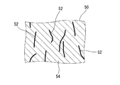
図4には、図3のIV−IV線に沿った断面が示されている。この図4には、ストリップ50のの一部が示されている。この図4において、上下方向がタイヤ2の周方向であり、左右方向がタイヤ2の軸方向であり、紙面との垂直方向がタイヤ2の半径方向である。
FIG. 4 shows a cross section taken along line IV-IV in FIG. In FIG. 4, a part of the
図4に示されているように、ストリップ50は、多数の短繊維52と、マトリクス54とで構成されている。換言すれば、このストリップ50は繊維補強ゴム(FRR)からなる。これら短繊維52は、マトリクス54に分散している。これら短繊維52の長手方向は、略周方向に沿っている。このストリップ50において、短繊維52は周方向に配向している。
As shown in FIG. 4, the
図5は、図4のストリップ50の短繊維52が示された模式図である。図5において、上下方向がタイヤ2の周方向であり、左右方向がタイヤ2の軸方向であり、紙面との垂直方向がタイヤ2の半径方向である。矢印θで示されているのは、短繊維52の角度である。角度θは、直線X1と直線X2とがなす角度である。直線X1は、周方向に延びている。直線X2は、短繊維52の一端52a及び他端52bを通過している。この角度θは、短繊維52の長手方向が周方向に対してなす角度である。角度θは、0°以上90°以下である。なお、図5中、両矢印Lで示されているのが繊維長である。この繊維長Lは、一端52aから他端52bまでの長さが計測されることにより得られる。
FIG. 5 is a schematic view showing the
ストリップ50がタイヤ2の剛性に効果的に寄与しうるとの観点から、角度θが20°以下である短繊維52の数の、短繊維52の総数に対する比率は、50%以上が好ましく、70%以上がより好ましく、90%以上が特に好ましい。比率の算出においては、ストリップ50の、周方向に沿った断面に露出した短繊維52の角度が、測定される。無作為に抽出された100本の短繊維52について、角度の測定がなされる。なお、角度θが20°以下である短繊維52の数の、短繊維52の総数に対する比率が90%以上である場合が、ストリップ50における短繊維52が周方向に配向している状態である。
From the viewpoint that the
前述したように、このタイヤ2では、ストリップ50において、短繊維52が周方向に配向している。この短繊維52による、ストリップ50の周方向の剛性への貢献の程度は、このストリップ50の半径方向又は軸方向の剛性への貢献の程度よりも大きい。このタイヤ2のストリップ50では、その剛性が、周方向の剛性が半径方向の剛性よりも大きくなるように整えられている。このストリップ50の剛性は、周方向の剛性が軸方向の剛性よりも大きくなるように整えられている。このストリップ50は、その剛性に関し、異方性を有している。詳述しないが、本発明においては、前述の、短繊維52の配合量に加え、用いる短繊維52の材質、長さ等を適宜調整することでストリップ50の周方向の剛性が整えられているのは言うまでもない。短繊維52の配合以外の方法で、このストリップ50の剛性が異方性を有するように整えられてもよい。
As described above, in the
このタイヤ2の製造では、複数のゴム部材がアッセンブリーされて、ローカバー(未加硫タイヤ2)が得られる。このローカバーが、モールドに投入される。ローカバーの外面は、モールドのキャビティ面と当接する。ローカバーの内面は、ブラダー又は中子に当接する。ローカバーは、モールド内で加圧及び加熱される。加圧及び加熱により、ローカバーのゴム組成物が流動する。加熱によりゴムが架橋反応を起こし、タイヤ2が得られる。そのキャビティ面に凸凹模様を有するモールドが用いられることにより、タイヤ2に凹凸模様が形成される。
In the manufacture of the
このタイヤ2の製造では、ストリップ50は、このストリップ50のためのゴム組成物を押し出しして、テープ状に成形することで準備される。前述したように、ストリップ50のためのゴム組成物は、例えば、トレッド4のベース層28のためのゴム組成物とは異なり、短繊維52を含んでいる。このため、このゴム組成物を押し出して成形したストリップ50においては、短繊維52は、その押出方向、言い換えれば、その長さ方向に配向している。
In the manufacture of the
このようにして準備されたストリップ50は、主溝42の半径方向内側に相当する位置において、その長さ方向をタイヤ2の周方向に一致させて巻回される。ストリップ50において短繊維52はその長さ方向に配向しているので、これにより、周方向に配向した短繊維52を含むストリップ50が得られる。このタイヤ2の製造では、ゴム組成物を押し出して形成したものを巻き回すことで、ストリップ50が得られる。このストリップ50の製造には、従来のタイヤで採用された、軸方向に延在する多数のコードを周方向に並列させた部品の製造のように、多数のステップは不要である。
The
このタイヤ2では、ストリップ50は周方向に配向した短繊維52を含んでいるので、このストリップ50は周方向において高い剛性を有している。特に、このタイヤ2では、ストリップ50の周方向の複素弾性率Esc*は、トレッド4、詳細には、トレッド4のベース層28の周方向の複素弾性率Ebc*よりも大きい。具体的には、このベース層28の複素弾性率Ebc*に対するストリップ50の周方向の複素弾性率Esc*の比は2以上である。これにより、ストリップ50が主溝42の底56の部分の剛性に効果的に寄与する。つまり、このタイヤ2では、主溝42の半径方向内側に、周方向の剛性が高いストリップ50が設けられており、このストリップ50が、主溝42の底56の部分の剛性、詳細には、この部分の周方向の剛性に寄与する。主溝42の底56の部分の剛性が高いので、特に、この部分における周方向の変形が抑えられる。このタイヤ2では、ベルト16が効果的に拘束され、この底56の部分の振動が効果的に抑制される。この観点から、この比は3以上が好ましく、5以上がより好ましい。一方、このストリップ50による剛性への貢献の程度が大きくなり過ぎると、乗り心地等の性能が損なわれるともに転がり抵抗が増大する恐れがある。この観点から、この比は15以下が好ましく、13以下がより好ましい。
In the
このタイヤ2では、トレッド4の内側にベルト16が設けられている。発明者らは、有限要素法(Finite Element Method;FEM)等による、振動伝達に関する詳細な検討により、軸方向の振動の減衰にベルト16が効果的に寄与するという知見を得ている。つまりこのタイヤ2では、このベルト16による振動の減衰効果もあって、つまり、ストリップ50とベルト16との相乗的な作用により、溝26の底56の部分の振動がかなり抑制される。振動の抑制は、小さな加振力を招来する。
In the
このタイヤ2では、加振力が小さくなる、すなわち、気柱共鳴音が低減される。しかもこの気柱共鳴音の低減のために、従来タイヤのように、軸方向の剛性確保のための部材を要しない。本発明によれば、生産性への影響を抑えつつ、気柱共鳴音の低減が達成された空気入りタイヤ2が得られる。
In the
図3に示されているように、主溝42の壁面48とその底56との間には角58が設けられている。このタイヤ2では、この角58は丸めとされている。符号G1は、一方の角58の一端における接線とこの角58の他端における接線との交点である。本発明においては、交点G1はこの主溝42の第一仮想角である。符号G2は、他方の角58の一端における接線とこの角58の他端における接線との交点である。本発明においては、交点G2はこの主溝42の第二仮想角である。両矢印Wgは、第一仮想角G1から第二仮想角G2までの距離を表している。本発明においては、この距離Wgが主溝42の底56の幅である。なお、主溝42において、底56の端が明確に特定できる場合には、この底56の一端から他端までの長さで、この底56の幅は表される。図3において、両矢印Wsはストリップ50の幅である。
As shown in FIG. 3, an
このタイヤ2では、溝26の底56の幅Wgに対するストリップ50の幅Wsの比は3以下が好ましい。これにより、このタイヤ2の走行状態において、リブ44を通じて伝えられる力の作用が適度に抑えられる。このタイヤ2では、乗り心地及び転がり抵抗が適切に維持される。この観点から、この比は2.5以下がより好ましい。主溝42の底56の部分の振動が効果的に抑制されるとの観点から、この比は1以上が好ましく、1.5以上がより好ましい。
In the
図3において、符号CSはストリップ50の幅方向中心である。符号CGは、主溝42の底56の幅方向中心である。
In FIG. 3, the symbol CS is the center of the
このタイヤ2では、ストリップ50が気柱共鳴音の低減に効果的に寄与するとの観点から、ストリップ50は、その幅方向中心CSが主溝42の底56の幅方向中心CGと軸方向において一致するように、このタイヤ2に設けられるのが好ましい。なお、本発明においては、軸方向に計測される中心CSから中心CGまでの距離が3mm以内である場合に、中心CSが中心CGと軸方向において一致していると判断される。
In the
前述したように、このタイヤ2のストリップ50では、その剛性が、周方向の剛性が半径方向の剛性よりも大きくなるように整えられている。言い換えれば、このタイヤ2では、ストリップ50の半径方向の剛性、すなわち、ストリップ50の半径方向の複素弾性率Esr*は、その周方向の剛性、すなわち、このストリップ50の周方向の複素弾性率Esc*よりも小さい。このため、このタイヤ2では、主溝42の半径方向内側に位置するストリップ50による半径方向の剛性への寄与は意外に小さい。このタイヤ2では、その走行状態において、リブ44を通じて伝えられる力の増幅が効果的に抑えられている。このタイヤ2では、乗り心地及び転がり抵抗が適切に維持される。この観点から、このタイヤ2では、ストリップ50の周方向の複素弾性率Esc*に対するこのストリップ50の半径方向の複素弾性率Esr*の比は、0.9以下が好ましい。ストリップ50が半径方向においても適度な剛性を有し、このストリップ50が振動の抑制により効果的に寄与するとの観点から、この比は0.1以上が好ましい。
As described above, the rigidity of the
前述したように、ストリップ50は短繊維52を周方向に配向させることで、この剛性の異方性が整えられている。このため、このタイヤ2では、ストリップ50の軸方向の剛性、すなわち、ストリップ50の軸方向の複素弾性率Esa*は、その半径方向の剛性、すなわち、このストリップ50の半径方向の複素弾性率Esr*と同等である。したがって、このタイヤ2では、ストリップ50の周方向の複素弾性率Esc*に対するこのストリップ50の軸方向の複素弾性率Esa*の比は、0.1以上が好ましく、0.9以下が好ましい。
As described above, the
このタイヤ2では、ストリップ50のためのゴム組成物における短繊維52の配合量は、基材ゴム100質量部に対して1質量部以上が好ましく、50質量部以下が好ましい。この短繊維52の配合量が1質量部以上に設定されることにより、ストリップ50が適度な強度を有する。このストリップ50は、気柱共鳴音の低減に寄与する。この観点から、この配合量は2質量部以上がより好ましい。この短繊維52の配合量が50質量部以下に設定されることにより、ストリップ50の剛性が適切に維持される。このタイヤ2では、乗り心地及び転がり抵抗が適切に維持される。この観点から、この配合量は40質量部以下がより好ましい。
In the
このタイヤ2では、短繊維52の平均長さLaは1μm以上が好ましく、100μm以下が好ましい。平均長さLaが1μm以上に設定されることにより、ストリップ50において、短繊維52の周方向への配向が達成される。このストリップ50は、気柱共鳴音の低減に寄与する。この観点から、この平均長さLaは5μm以上が好ましい。平均長さLaが100μm以下に設定されることにより、短繊維52がマトリクス54に良好に分散しうる上に、短繊維52とこの短繊維52の周りに存在するゴムとが十分に接合されうる。このタイヤ2では、ストリップ50による耐久性への影響が効果的に抑えられる。この観点から、平均長さLaは90μm以下が好ましい。なお、この平均長さLaは、無作為に抽出された100本の短繊維52について計測された長さ(前述の繊維長L)の平均値で表される。
In the
このタイヤ2では、短繊維52の平均直径Daは、0.04μm以上が好ましい。平均直径Daが0.04μm以上である短繊維52により、ストリップ50の強度が十分に高められる。マトリクス54への分散性の観点から、平均直径Daは500μm以下が好ましい。なお、この平均直径Daは、無作為に抽出された100本の短繊維52について計測された直径の平均値で表される。この短繊維52の直径は、実体顕微鏡で計測される。
In the
このタイヤ2では、周方向に配向しているとはいえ、ストリップ50は短繊維52を含んでいる。この短繊維52は、ストリップ50の半径方向の剛性にも若干寄与する。特に、このタイヤ2では、このストリップ50の剛性は、その半径方向の剛性がベース層28の剛性よりも僅かに高くなるように整えられている。このため、このストリップ50は、溝26の底56の部分における半径方向の変形を効果的に抑える。これにより、このタイヤ2では、気柱共鳴音がより効果的に低減されている。この観点から、このベース層28の複素弾性率Ebc*に対するストリップ50の半径方向の複素弾性率Esr*の比は1.1以上が好ましい。前述したように、ストリップ50の半径方向の剛性が大きくなり過ぎると、乗り心地が低下し転がり抵抗が増大する恐れがある。この観点から、この比は1.9以下が好ましい。このタイヤ2では、ストリップ50の軸方向の複素弾性率Esa*は、このストリップ50の半径方向の複素弾性率Esr*と同等であるので、ベース層28の複素弾性率Ebc*に対するストリップ50の軸方向の複素弾性率Esr*の比は1.1以上が好ましく、1.9以下が好ましい。
In the
以下、実施例によって本発明の効果が明らかにされるが、この実施例の記載に基づいて本発明が限定的に解釈されるべきではない。 Hereinafter, the effects of the present invention will be clarified by examples. However, the present invention should not be construed in a limited manner based on the description of the examples.
[実施例1]
図1−2に示されたタイヤを製作した。このタイヤのサイズは、235/45R18である。実施例1の諸元は、下記の表1に示される通りである。主溝には、このサイズのタイヤで通常採用される溝の形状が採用されている。主溝が浅溝でないことが、表1の「浅溝」の欄に「N」で表されている。トレッドのベース層では、周方向の複素弾性率Ebc*は4.0MPaに設定された。
[Example 1]
The tire shown in FIG. 1-2 was manufactured. The size of this tire is 235 / 45R18. The specifications of Example 1 are as shown in Table 1 below. The main groove adopts a groove shape that is usually employed in tires of this size. The fact that the main groove is not a shallow groove is indicated by “N” in the “shallow groove” column of Table 1. In the tread base layer, the circumferential complex elastic modulus Ebc * was set to 4.0 MPa.
[比較例1]
ストリップを採用しなかった他は実施例1と同様にして、比較例1のタイヤを得た。
[Comparative Example 1]
A tire of Comparative Example 1 was obtained in the same manner as Example 1 except that no strip was used.
[比較例2]
ストリップを採用せず、主溝の深さを浅くした他は実施例1と同様にして、比較例2のタイヤを得た。主溝が浅溝であることが、表1の「浅溝」の欄に「Y」で表されている。
[Comparative Example 2]
A tire of Comparative Example 2 was obtained in the same manner as in Example 1 except that the strip was not used and the depth of the main groove was reduced. The fact that the main groove is a shallow groove is indicated by “Y” in the “shallow groove” column of Table 1.
[比較例3]
ストリップの幅Wsをベルトの幅と同等とした、すなわち、ベルトの幅と同等の幅を有する一枚のシートを準備し、これをストリップとしてバンドに積層した他は実施例1と同様にして、比較例3のタイヤを得た。ベルトの幅と同等の幅のストリップを採用したことが、表1の「Ws/Wg」の欄に「BW」で表されている。
[Comparative Example 3]
The strip width Ws was made equal to the width of the belt, that is, a single sheet having a width equivalent to the width of the belt was prepared, and this was laminated on the band as a strip in the same manner as in Example 1, A tire of Comparative Example 3 was obtained. The fact that a strip having a width equal to the width of the belt is employed is indicated by “BW” in the “Ws / Wg” column of Table 1.
[比較例4]
ストリップの周方向の複素弾性率Esc*、及び、その軸方向の複素弾性率Esa*を変えて、ベース層の複素弾性率Ebc*に対する複素弾性率Esc*の比(Esc*/Ebc*)及び複素弾性率Ebc*に対する複素弾性率Esa*の比(Esa*/Ebc*)を下記の表1に示される通りとした他は実施例1と同様にして、比較例4のタイヤを得た。この比較例4のストリップでは、短繊維は軸方向に配向している。
[Comparative Example 4]
By changing the complex elastic modulus Esc * in the circumferential direction of the strip and the complex elastic modulus Esa * in the axial direction, the ratio of the complex elastic modulus Esc * to the complex elastic modulus Ebc * of the base layer (Esc * / Ebc *) and A tire of Comparative Example 4 was obtained in the same manner as in Example 1 except that the ratio (Esa * / Ebc *) of the complex elastic modulus Esa * to the complex elastic modulus Ebc * was as shown in Table 1 below. In the strip of Comparative Example 4, the short fibers are oriented in the axial direction.
[実施例2−8]
主溝の底の幅Wgに対するストリップの幅Wsの比(Ws/Wg)を下記の表2に示される通りとした他は実施例1と同様にして、実施例2−8のタイヤを得た。
[Example 2-8]
A tire of Example 2-8 was obtained in the same manner as in Example 1 except that the ratio (Ws / Wg) of the strip width Ws to the bottom width Wg of the main groove was as shown in Table 2 below. .
[実施例9−14]
ストリップの周方向の複素弾性率Esc*、その半径方向の複素弾性率Esr*、及び、その軸方向の複素弾性率Esa*を変えて、ベース層の複素弾性率Ebc*に対する複素弾性率Esc*の比(Esc*/Ebc*)、複素弾性率Ebc*に対する複素弾性率Esr*の比(Esr*/Ebc*)及び複素弾性率Ebc*に対する複素弾性率Esa*の比(Esa*/Ebc*)を下記の表3に示される通りとした他は実施例1と同様にして、実施例9−14のタイヤを得た。
[Examples 9-14]
By changing the complex elastic modulus Esc * in the circumferential direction of the strip, the complex elastic modulus Esr * in the radial direction, and the complex elastic modulus Esa * in the axial direction, the complex elastic modulus Esc * with respect to the complex elastic modulus Ebc * of the base layer is changed. Ratio (Esc * / Ebc *), ratio of complex elastic modulus Esr * to complex elastic modulus Ebc * (Esr * / Ebc *), and ratio of complex elastic modulus Esa * to complex elastic modulus Ebc * (Esa * / Ebc *) The tires of Examples 9-14 were obtained in the same manner as in Example 1 except that, as shown in Table 3 below.
[通過騒音]
タイヤをリム(サイズ=8.0J×18)に組み込み、このタイヤに空気を充填した。タイヤの内圧は、平均で176kPaであった。このタイヤを、排気量が2000ccである乗用車に装着した。ドライバーに、この乗用車をアスファルトの路面で構成されたテストコースで運転させて、ECE R117に準拠して通過騒音を計測した。タイヤに付与された荷重は、平均で4.60kNであった。
[Passing noise]
The tire was assembled in a rim (size = 8.0 J × 18), and the tire was filled with air. The average internal pressure of the tire was 176 kPa. This tire was mounted on a passenger car having a displacement of 2000 cc. The driver was allowed to drive the passenger car on a test course composed of an asphalt road surface, and the passing noise was measured in accordance with ECE R117. The load applied to the tire was 4.60 kN on average.
図6には、テストコースに設けられた通過騒音の計測箇所の様子が模式的に示されている。この図6において、A−A線は計測の開始位置である。B−B線は、計測の終了位置である。乗用車は、その幅方向中心がC−C線と概ね重なるように、A−A線とB−B線との間を走行させられた。A−A線からB−B線までの距離は、20mに設定された。 FIG. 6 schematically shows the state of measurement of passing noise provided in the test course. In FIG. 6, the AA line is the measurement start position. A BB line is a measurement end position. The passenger car was run between the AA line and the BB line so that the center in the width direction substantially overlaps the CC line. The distance from the AA line to the BB line was set to 20 m.
A−A線とB−B線との中間地点には、通過騒音を計測するために、2つのマイクロフォン(図6の符号S)が設置された。これらのマイクロフォンSはC−C線を挟んで配置され、C−C線から各マイクロフォンSまでの距離は7.45〜7.55mの範囲で設定された。このマイクロフォンSの地上高さは、1.18〜1.22mの範囲で設定された。乗用車は、2つのマイクロフォンSの間を通過させられた。 Two microphones (symbol S in FIG. 6) were installed at an intermediate point between the AA line and the BB line in order to measure passing noise. These microphones S are arranged across the CC line, and the distance from the CC line to each microphone S is set in the range of 7.45 to 7.55 m. The ground height of the microphone S was set in the range of 1.18 to 1.22 m. The passenger car was passed between the two microphones S.
この通過騒音の計測では、乗用車の先端がA−A線に到達すると、ギアがニュートラルの状態にされ、エンジンが止められた。乗用車は、B−B線に向かって惰力で走行させられた。そしてこのA−A線からB−B線まで走行する際に発生した通過騒音が、マイクロフォンSで計測された。この計測結果から、800〜1000Hz付近の主溝気柱共鳴音のピークレベルが把握された。70〜90km/hの範囲の速度でピークレベルを計測し、この計測で得た複数のピークレベルを用いて回帰式による演算処理をすることで、80km/hの速度におけるピークレベルを求めた。このピークレベルに関して、比較例1のピークレベルとの差を算出した。この結果が、下記の表1−3に示されている。数値が負である場合が気柱共鳴音が比較例1のそれよりも小さいことを表している。したがって、この数値が小さいほど気柱共鳴音の低減が図られており好ましい。0.3db(A)以上の低減が、本発明の目標とされた。 In the measurement of the passing noise, when the front end of the passenger car reached the AA line, the gear was set to the neutral state and the engine was stopped. The passenger car was driven by repulsion toward the BB line. The passing noise generated when traveling from the AA line to the BB line was measured by the microphone S. From this measurement result, the peak level of the main groove air column resonance sound in the vicinity of 800 to 1000 Hz was grasped. A peak level was measured at a speed in the range of 70 to 90 km / h, and a peak level at a speed of 80 km / h was obtained by performing a calculation process using a regression equation using a plurality of peak levels obtained by this measurement. Regarding this peak level, the difference from the peak level of Comparative Example 1 was calculated. The results are shown in Table 1-3 below. A case where the numerical value is negative indicates that the air column resonance is smaller than that of Comparative Example 1. Therefore, it is preferable that the numerical value is smaller because the air column resonance is reduced. A reduction of 0.3 db (A) or more was targeted by the present invention.
[ウェット]
通過騒音の計測で用いた乗用車と同様に、乗用車が準備された。ドライバーに、この乗用車を、半径100mのアスファルト路面のテストコースで運転させて、ウェットに関する評価を実施した。このテストコースには、水深10mm、長さ20mの水たまりが設けられた。80km/hの速度でこの水たまりに乗用車を進入させて、この進入時の前輪に作用する平均横加速度(横G)を計測した。この結果が、指数で、下記の表1−3に示されている。数値が大きいほど横Gが大きく、ウェットグリップに優れる、言い換えれば、排水性に優れることを表している。ウエットグリップの低下代の許容範囲は、5%未満に設定された。なお、グリップの低下代を2%以内とすることが目標に設定された。
[Wet]
A passenger car was prepared in the same manner as the passenger car used in the measurement of passing noise. The driver was allowed to drive the passenger car on a test course on an asphalt road surface with a radius of 100 m to evaluate wetness. This test course was provided with a puddle having a depth of 10 mm and a length of 20 m. A passenger car was allowed to enter the puddle at a speed of 80 km / h, and the average lateral acceleration (lateral G) acting on the front wheels during this approach was measured. This result is an index and is shown in Table 1-3 below. The larger the numerical value, the larger the lateral G and the better the wet grip, in other words, the better the drainage. The tolerance of the allowance for lowering the wet grip was set to less than 5%. The goal was to set the allowance for grip reduction within 2%.
[乗り心地]
通過騒音の計測で用いた乗用車と同様に、乗用車が準備された。ドライバーに、この乗用車を、アスファルト路面のテストコースで運転させて、乗り心地を官能的に評価させた。この結果が、指数として下記の表1−3に示されている。数値が大きいほど好ましい。乗り心地の低下代の許容範囲は、5%未満に設定された。なお、乗り心地の低下代を2%以内することが目標に設定された。
[Ride comfort]
A passenger car was prepared in the same manner as the passenger car used in the measurement of passing noise. The driver was allowed to drive the passenger car on a test course on the asphalt road surface and evaluated the ride comfortably. The results are shown in Tables 1-3 below as indices. Larger numbers are preferable. The allowable range for the reduction in ride comfort was set to less than 5%. The goal was to reduce the cost of lowering the ride comfort to 2% or less.
[転がり抵抗係数]
転がり抵抗試験機を用い、下記の測定条件で転がり抵抗係数(RRC)を測定し、比較例1の転がり抵抗係数との差を算出した。
使用リム:8.0J×18(アルミニウム合金製)
内圧:220kPa
荷重:4.6kN
速度:80km/h
この結果が、下記の表1−3に示されている。数値が正である場合が転がり抵抗が比較例1のそれよりも大きく悪化したことを表している。したがって、この数値が小さいほど転がり抵抗の増加が抑えられており好ましい。転がり抵抗の増加の許容範囲は、0.5未満に設定された。転がり抵抗の増加を0.2以内にすることが、本発明の目標とされた。
[Rolling resistance coefficient]
Using a rolling resistance tester, the rolling resistance coefficient (RRC) was measured under the following measurement conditions, and the difference from the rolling resistance coefficient of Comparative Example 1 was calculated.
Rim used: 8.0J × 18 (aluminum alloy)
Internal pressure: 220 kPa
Load: 4.6kN
Speed: 80km / h
The results are shown in Table 1-3 below. A case where the numerical value is positive indicates that the rolling resistance has become worse than that of Comparative Example 1. Therefore, it is preferable that the numerical value is smaller because an increase in rolling resistance is suppressed. The allowable range of increase in rolling resistance was set to less than 0.5. The goal of the present invention was to increase the rolling resistance within 0.2.

表1−3に示されるように、実施例のタイヤでは、比較例のタイヤに比べて評価が高い。この評価結果から、本発明の優位性は明らかである。 As shown in Table 1-3, the tire of the example has a higher evaluation than the tire of the comparative example. From this evaluation result, the superiority of the present invention is clear.
以上説明された気柱共鳴音を低減するための技術は、種々のタイヤにも適用されうる。 The technology for reducing the air column resonance described above can be applied to various tires.
2・・・タイヤ
4・・・トレッド
6・・・サイドウォール
10・・・クリンチ
12・・・ビード
14・・・カーカス
16・・・ベルト
18・・・バンド
24・・・トレッド面
26・・・溝
28・・・ベース層
30・・・キャップ層
36・・・カーカスプライ
38・・・内側層
40・・・外側層
42・・・主溝
44・・・リブ
46・・・横溝
48・・・壁面
50・・・ストリップ
52・・・短繊維
54・・・マトリクス
56・・・底
2 ...
Claims (4)
上記ベルトが上記トレッドの半径方向内側に位置しており、このベルトが並列された多数のコードを含んでおり、それぞれのコードが赤道面に対して傾斜しており、
上記トレッドが、周方向に延在する溝を備えており、
上記ストリップが、半径方向において、上記溝と上記ベルトとの間に位置しており、
上記ストリップが、上記ベルトの幅よりも小さな幅を有しており、
上記トレッドの周方向の弾性率に対する上記ストリップの周方向の弾性率の比が2以上である、空気入りタイヤ。 With tread, belt and strip,
The belt is located radially inward of the tread, the belt includes a number of cords arranged in parallel, and each cord is inclined with respect to the equator plane;
The tread has a groove extending in the circumferential direction,
The strip is located in the radial direction between the groove and the belt;
The strip has a width smaller than the width of the belt;
A pneumatic tire, wherein a ratio of a circumferential elastic modulus of the strip to a circumferential elastic modulus of the tread is 2 or more.
Priority Applications (1)
| Application Number | Priority Date | Filing Date | Title |
|---|---|---|---|
| JP2016045508A JP2017159774A (en) | 2016-03-09 | 2016-03-09 | Pneumatic tire |
Applications Claiming Priority (1)
| Application Number | Priority Date | Filing Date | Title |
|---|---|---|---|
| JP2016045508A JP2017159774A (en) | 2016-03-09 | 2016-03-09 | Pneumatic tire |
Publications (1)
| Publication Number | Publication Date |
|---|---|
| JP2017159774A true JP2017159774A (en) | 2017-09-14 |
Family
ID=59853421
Family Applications (1)
| Application Number | Title | Priority Date | Filing Date |
|---|---|---|---|
| JP2016045508A Pending JP2017159774A (en) | 2016-03-09 | 2016-03-09 | Pneumatic tire |
Country Status (1)
| Country | Link |
|---|---|
| JP (1) | JP2017159774A (en) |
-
2016
- 2016-03-09 JP JP2016045508A patent/JP2017159774A/en active Pending
Similar Documents
| Publication | Publication Date | Title |
|---|---|---|
| EP3130479B1 (en) | Pneumatic radial tire for use on passenger vehicle | |
| EP3130482B1 (en) | Pneumatic radial tire for use on passenger vehicle | |
| JP6249522B2 (en) | Pneumatic tire | |
| WO2015129595A1 (en) | Pneumatic tire | |
| US10773554B2 (en) | Pneumatic tire | |
| US11752809B2 (en) | Pneumatic tire | |
| JP6285751B2 (en) | Pneumatic tire | |
| WO2017110643A1 (en) | Pneumatic tire | |
| JP2009057022A (en) | Pneumatic tire | |
| US20200016941A1 (en) | Pneumatic tire | |
| JP6720537B2 (en) | Pneumatic tire | |
| JP6939783B2 (en) | Pneumatic tires | |
| JP2009035230A (en) | Pneumatic tire | |
| JP2008254619A (en) | Pneumatic tire | |
| WO2017110636A1 (en) | Pneumatic tire | |
| JP2018130977A (en) | Pneumatic tire | |
| JP2013079050A (en) | Pneumatic tire | |
| JP6790547B2 (en) | Pneumatic tires | |
| JP6457735B2 (en) | Pneumatic tire | |
| JP2002301912A (en) | Pneumatic tire | |
| JP2017159774A (en) | Pneumatic tire | |
| JP2009154764A (en) | Pneumatic tire | |
| JP6457821B2 (en) | Pneumatic tire | |
| JP6177282B2 (en) | Pneumatic tire | |
| JP2015174459A (en) | pneumatic tire |
Legal Events
| Date | Code | Title | Description |
|---|---|---|---|
| A621 | Written request for application examination |
Free format text: JAPANESE INTERMEDIATE CODE: A621 Effective date: 20190107 |
|
| A977 | Report on retrieval |
Free format text: JAPANESE INTERMEDIATE CODE: A971007 Effective date: 20200127 |
|
| A131 | Notification of reasons for refusal |
Free format text: JAPANESE INTERMEDIATE CODE: A131 Effective date: 20200212 |
|
| A521 | Written amendment |
Free format text: JAPANESE INTERMEDIATE CODE: A523 Effective date: 20200220 |
|
| RD02 | Notification of acceptance of power of attorney |
Free format text: JAPANESE INTERMEDIATE CODE: A7422 Effective date: 20200220 |
|
| A02 | Decision of refusal |
Free format text: JAPANESE INTERMEDIATE CODE: A02 Effective date: 20200519 |