JP2017159452A - Printer and printing method - Google Patents
Printer and printing method Download PDFInfo
- Publication number
- JP2017159452A JP2017159452A JP2016042997A JP2016042997A JP2017159452A JP 2017159452 A JP2017159452 A JP 2017159452A JP 2016042997 A JP2016042997 A JP 2016042997A JP 2016042997 A JP2016042997 A JP 2016042997A JP 2017159452 A JP2017159452 A JP 2017159452A
- Authority
- JP
- Japan
- Prior art keywords
- job
- image data
- ink sheet
- printing
- time
- Prior art date
- Legal status (The legal status is an assumption and is not a legal conclusion. Google has not performed a legal analysis and makes no representation as to the accuracy of the status listed.)
- Granted
Links
Images


Abstract
Description
本発明は、プリンタおよび印刷方法に関する。 The present invention relates to a printer and a printing method.
熱転写方式により画像をペーパーに印刷する熱転写型のプリンタは、サーマルプリンタ、昇華型のプリンタ等とも呼ばれる。 A thermal transfer printer that prints an image on paper by a thermal transfer method is also called a thermal printer, a sublimation printer, or the like.
熱転写型のプリンタは、一般的に、サーマルヘッドおよびプラテンローラーを備える。インクシートおよびペーパーは、サーマルヘッドとプラテンローラーとの間隙において互いに圧接させられる。インクシートおよびペーパーが互いに圧接させられたまま、インクシートおよびペーパーの各々が搬送され、サーマルヘッドによりインクシートが加熱される。これにより、インクシートからペーパーにインクが熱転写され、画像がペーパーに形成される。熱転写は、1ラインごとに行われる。 A thermal transfer type printer generally includes a thermal head and a platen roller. The ink sheet and paper are pressed against each other in the gap between the thermal head and the platen roller. Each of the ink sheet and the paper is conveyed while the ink sheet and the paper are pressed against each other, and the ink sheet is heated by the thermal head. Thereby, the ink is thermally transferred from the ink sheet to the paper, and an image is formed on the paper. Thermal transfer is performed for each line.
熱転写型のプリンタにおいては、一般的に、画像をイエロー(Y)成分、マゼンダ(M)成分およびシアン(C)成分に分解することにより得られるY成分画像、M成分画像およびC成分画像を重ねてペーパーに形成することにより画像がペーパーに形成される。また、形成された画像に重ねてオーバーコート(OP)層が形成される。OP層は、印刷物の耐候性および耐指紋性を向上させる。 In a thermal transfer type printer, generally, an Y component image, an M component image, and a C component image obtained by decomposing an image into a yellow (Y) component, a magenta (M) component, and a cyan (C) component are superimposed. The image is formed on the paper by forming it on the paper. In addition, an overcoat (OP) layer is formed on the formed image. The OP layer improves the weather resistance and fingerprint resistance of the printed material.
熱転写型のプリンタにおいて、大判サイズを有する画面を印刷するためのインクシートを使用して各々が小判サイズを有する複数個の画像が印刷される場合がある。例えば、6×8インチサイズを有する画面を印刷するためのインクシートを使用して各々が6×4インチサイズを有する2個の画像が印刷される場合、8×12インチサイズを有する画面を印刷するためのインクシートを使用して各々が8×4インチサイズを有する3個の画像が印刷される場合等がある。特許文献1および2の各々に記載された技術はその例である。
In a thermal transfer type printer, a plurality of images each having a small size may be printed using an ink sheet for printing a screen having a large size. For example, if two images each having a 6 × 4 inch size are printed using an ink sheet for printing a screen having a 6 × 8 inch size, the screen having an 8 × 12 inch size is printed. In some cases, three images each having an 8 × 4 inch size are printed using the ink sheet. The techniques described in
特許文献1に記載された技術においては、各々が6×4インチサイズの画面である奇数枚の画面がプリントされる場合に、6×8インチサイズのインクリボンを使用して2画面がプリントされる。2画面がプリントされる場合は、1画像目のプリントが終了した後に、インクリボンが巻き戻され、インクリボンの未使用部分を使用して2画像目がプリントされる。これにより、インクリボンにロスが出ることが抑制される。ただし、1画像目が高濃度でありインクリボンが受けた熱ダメージの大きさが所定の値以上であると判定された場合は、インクリボンが巻き戻されず、インクリボンの新たな部分が使用される。これにより、インクリボンの破断等が抑制される。
In the technique described in
特許文献2に記載された技術においては、各々がLサイズの写真である奇数枚の写真が印刷される場合に、2Lサイズ用インクリボンを使用して2枚の写真が印刷され、Lサイズ用インクリボンを使用して半端の1枚の写真が印刷される。これにより、1枚のLサイズの写真が2Lサイズ用インクリボンを使用して印刷されることが抑制され、2Lサイズ用インクリボンの後半部分が使用されないで残ることが抑制される。
In the technique described in
特許文献3に記載された技術は、インクシートには直接的には関連しない。しかし、特許文献3に記載された技術は、ジョブの連結に関する。特許文献3に記載された技術においては、印刷中の印刷ジョブの印刷処理の終了が近い場合は、続いて印刷処理が行われる印刷ジョブが印刷データに変換され、変換された印刷データがプリンタに入力される。印刷中の印刷ジョブの印刷処理の終了が近くない場合は、続いて印刷処理が行われる印刷ジョブが第1の印刷データに変換されるが、変換状態が完了させられずに待機処理が実行され、新たに取得した印刷ジョブが第2の印刷データに変換され、第2の印刷データが第1の印刷データに加えられる連結処理が行われる。これにより、印刷ジョブ間で生じるカット処理、位置合わせ処理等の時間、カットで生じる無駄な記録紙等が減じられる。
The technique described in
特許文献1に記載された技術によれば、大判サイズを有する画面を印刷するためのインクシートを使用して各々が小判サイズを有する奇数個の画像が印刷される場合に、インクシートが巻き戻されることもあるし、インクシートが巻き戻されないこともある。インクシートが巻き戻される場合には、インクシートが巻き戻されない場合と比較して、ダメージを受けたインクシートを使用して印刷が行われるため、印刷の品位が低下する。一方、インクシートが巻き戻されない場合は、インクシートの一部が使用されずに無駄になる。
According to the technique described in
特許文献2に記載された技術によれば、インクシートの一部が無駄になることが抑制される。しかし、特許文献2に記載された技術は、インクシートの種類を減らしたいという要求には応えられない。
According to the technique described in
本発明は、これらの問題を解決するためになされる。本発明が解決しようとする課題は、第1のサイズを有する画面を印刷するために使用されるインクシート面を有するインクシートを使用して各々が第1のサイズより小さい第2のサイズを有する複数個の画像を印刷する場合に、インクシートの種類を増やさずに、印刷の品位が低下することを抑制し、インクシートの一部が無駄になることを抑制することである。 The present invention is made to solve these problems. The problem to be solved by the present invention is to use an ink sheet having an ink sheet surface used to print a screen having a first size, each having a second size that is smaller than the first size. When printing a plurality of images, without increasing the type of ink sheet, it is possible to suppress a decrease in printing quality and to prevent a part of the ink sheet from being wasted.
本発明は、プリンタおよび印刷方法に関する。 The present invention relates to a printer and a printing method.
インクシートは、第1のサイズを有する画面を印刷するために使用されるインクシート面を有する。 The ink sheet has an ink sheet surface that is used to print a screen having a first size.
少なくとも1個のジョブが受信され、受信された少なくとも1個のジョブについてインクシートを使用して印刷が行われる。印刷は、下記のように行われる。下記においては、第1の画像データ、第2の画像データ、第3の画像データおよび第4の画像データがそれぞれ第1の画像、第2の画像、第3の画像および第4の画像を表現し、第1の画像、第2の画像、第3の画像および第4の画像の各々が第1のサイズより小さい第2のサイズを有する。 At least one job is received and printing is performed using the ink sheet for the received at least one job. Printing is performed as follows. In the following, the first image data, the second image data, the third image data, and the fourth image data represent the first image, the second image, the third image, and the fourth image, respectively. Each of the first image, the second image, the third image, and the fourth image has a second size that is smaller than the first size.
少なくとも1個のジョブが第1の画像データおよび第2の画像データを含み、第1の画像データに続いて第2の画像データが受信され、第1の画像データの受信が終了されてから第2の画像データの受信が開始されるまでの第1の時間が第1の待機時間より短い場合は、第1の画像および第2の画像がインクシート面を1回使用して連結して印刷される第1の連結が行われる。 At least one job includes the first image data and the second image data, the second image data is received following the first image data, and the reception of the first image data is terminated. When the first time until the reception of the second image data is started is shorter than the first standby time, the first image and the second image are connected and printed using the ink sheet surface once. The first connection is performed.
第1の時間が第1の待機時間より長い場合は、第1の連結が行われない。 If the first time is longer than the first waiting time, the first connection is not performed.
少なくとも1個のジョブが第1のジョブおよび第2のジョブを含み、第1のジョブが第3の画像データを含み、第2のジョブが第4の画像データを含み、第1のジョブにおいて第3の画像データが最後に受信され、第2のジョブにおいて第4の画像データが最初に受信され、第3の画像データの受信が終了されてから第4の受信データの受信が開始されるまでの第2の時間が第2の待機時間より短い場合は、第3の画像および第4の画像をインクシート面を1回使用して連結して印刷する第2の連結が行われる。 At least one job includes a first job and a second job, the first job includes third image data, the second job includes fourth image data, and the first job includes The third image data is received last, the fourth image data is received first in the second job, and the reception of the fourth reception data is started after the reception of the third image data is completed. When the second time is shorter than the second standby time, the second connection is performed in which the third image and the fourth image are connected and printed using the ink sheet surface once.
第2の時間が第2の待機時間より長い場合は、第2の連結が行われない。 If the second time is longer than the second waiting time, the second connection is not performed.
第1のサイズを有する画面を印刷するために使用されるインクシート面を有するインクシートを使用して各々が第1のサイズより小さい第2のサイズを有する複数個の画像が印刷される場合に、インクシート面を1回使用して複数個の画像を連結して印刷できる場合が多くなる。これにより、インクシートの種類を増やさずに、印刷の品位が低下することが抑制され、インクシートの一部が無駄になることが抑制される。 When a plurality of images each having a second size smaller than the first size are printed using an ink sheet having an ink sheet surface used to print a screen having the first size. In many cases, a plurality of images can be connected and printed using the ink sheet surface once. As a result, it is possible to suppress a decrease in print quality without increasing the types of ink sheets, and to prevent a part of the ink sheet from being wasted.
1 実施の形態1
1.1 印刷システム
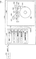
図1は、実施の形態1のプリンタを備える印刷システムを示すブロック図である。
1
1.1 Printing System FIG. 1 is a block diagram illustrating a printing system including the printer according to the first embodiment.
図1に示される印刷システム1000は、ホストパーソナルコンピュータ(PC)1022およびプリンタ1024を備える。印刷システム1000がこれらの構成物以外の構成物を備えてもよい。
A
プリンタ1024は、ホストPC1022に通信可能に接続される。
The
1.2 プリンタ
プリンタ1024は、熱転写型のプリンタであり、印刷部1042および制御部1044を備える。
1.2 Printer The
印刷部1042は、ペーパーロール1062、ペーパー1064、インクボビン1066、インクシート1068、インクボビン1070、ピンチローラー1072、グリップローラー1074、サーマルヘッド1076、プラテンローラー1078、カット機構1080、パルスモータ1082およびパルスモータ1084を備える。制御部1044は、画像データ生成部1102、サーマルヘッド制御部1104、インクシート駆動制御部1106、ペーパー駆動制御部1108および待機時間制御部1110を備える。画像データ生成部1102は、メモリ1122を備える。プリンタ1024がこれらの構成物以外の構成物を備えてもよい。
The
1.3 ホストPCとプリンタとの間の通信
印刷システム1000が画像を印刷する場合は、ホストPC1022およびプリンタ1024が互いに通信を行い、画像データを含むジョブがホストPC1022からプリンタ1024へ転送される。ジョブは、プリントジョブ等とも呼ばれ、印刷の処理の単位になる。
1.3 Communication between Host PC and Printer When the
ホストPC1022は、プリンタドライバその他のプリンタ制御用のソフトウェアを実行しプリンタ制御用のソフトウェアにしたがって動作することにより、ジョブを生成する。ホストPC1022は、オペレーションシステムまたはアプリケーションを実行しオペレーションシステムまたはアプリケーションにしたがって動作することにより、プリンタ1024がジョブを受信できる状態であるか否かを示す情報をプリンタ1024から受信し、プリンタ1024がジョブを受信できる状態であることが当該情報により示されている場合は生成したジョブをプリンタ1024に送信する。ホストPC1022は、生成した複数個のジョブの各々についてこれらの処理を行うことにより、生成した複数個のジョブをプリンタ1024に順次に送信する。
The
プリンタ1024は、ジョブを受信できる状態であるか否かを示す情報をホストPC1022に送信する。当該情報においては、メモリ1122がジョブの受信に必要な空き容量を有する場合に、ジョブを受信できる状態であることが示される。プリンタ1024は、ジョブをホストPC1022から受信し、受信したジョブに含まれる画像データにより表現される画像をペーパー1064に印刷する。プリンタ1024は、複数個のジョブの各々についてこれらの処理を行うことにより、複数個のジョブについて順次に印刷を行う。プリンタ1024は、複数個のジョブを受信した場合は、ジョブを受信した順にジョブについて印刷を行う。
The
1.4 印刷部
印刷部1042においては、ペーパーロール1062に巻かれたペーパー1064がペーパーロール1062から引き出される。引き出されたペーパー1064は、ピンチローラー1072とグリップローラー1074とに挟まれる。挟まれたペーパー1064は、ピンチローラー1072およびグリップローラー1074の回転により搬送され、サーマルヘッド1076とプラテンローラー1078との間隙1142およびカット機構1080を通過させられる。ピンチローラー1072およびグリップローラー1074は、ペーパー1064を搬送する搬送機構を構成する。ピンチローラー1072およびグリップローラー1074からなる搬送機構が他の搬送機構に置き換えられてもよい。ペーパー1064が被転写体となりうる他の種類の記録媒体に置き換えられてもよい。
1.4 Printing Unit In the
印刷部1042においては、インクボビン1066に巻かれたインクシート1068がインクボビン1066から引き出され、引き出されたインクシート1068が間隙1142を通過し、通過したインクシート1068がインクボビン1070に巻き取られる。インクボビン1066およびインクボビン1070は、それぞれパルスモータ1082およびパルスモータ1084により回転させられる。これにより、インクシート1068がインクボビン1066からインクボビン1070へ搬送され、インクボビン1070からインクボビン1066へ逆搬送される。インクボビン1066、インクボビン1070、パルスモータ1082およびパルスモータ1084は、インクシート1068を搬送する搬送機構を構成する。インクボビン1066、インクボビン1070、パルスモータ1082およびパルスモータ1084からなる搬送機構が他の搬送機構に置き換えられてもよい。インクシート1068には、インクが塗布されている。
In the
印刷部1042においては、インクシート1068からペーパー1064へのインクの熱転写が行われる場合に、ペーパー1064およびインクシート1068が間隙1142において重ね合わされ、重ね合わされたペーパー1064およびインクシート1068がサーマルヘッド1076およびプラテンローラー1078に挟まれ、ペーパー1064およびインクシート1068が互いに圧接させられ、サーマルヘッド1076によりインクシート1068が加熱される。印刷部1042においては、ペーパー1064およびインクシート1068を搬送しながら当該熱転写を繰り返し行うことにより、入力された印刷用の画像データにより表現される画像がペーパー1064に印刷される。
In the
印刷部1042においては、画像が印刷されたペーパー1064がカット機構1080によりカットされる。これにより、画像が印刷されたペーパー片からなる印刷物が得られる。得られた印刷物は、プリンタ1024から排出される。
In the
1.5 制御部
画像データ生成部1102は、ホストPC1022からプリンタ1024へ転送されてきたジョブを受信し、受信したジョブに含まれる画像データをメモリ1122に一時保持させ、使用されるインクシート1068に適合する印刷用の画像データを一時保持された画像データから生成し、生成した印刷用の画像データを印刷部1042へ出力する。これにより、画像データ生成部1102は、受信したジョブから印刷用の画像データを生成し、生成した印刷用の画像データにより表現される画像を印刷部1042に印刷させる。画像データ生成部1102は、複数個の画像データがメモリ1122に一時保持されている場合は、画像データを受信した順に画像データを印刷用の画像データに変換する。
1.5 Control Unit The image
ジョブに含まれる画像データは、イエロー(Y)色成分、マゼンタ(M)色成分およびシアン(C)色成分からなるYMC画像データであり、印刷される画像を表現する。画像データが、Y成分、M成分およびC成分以外の複数個の色成分からなる画像データであってもよい。 The image data included in the job is YMC image data including a yellow (Y) color component, a magenta (M) color component, and a cyan (C) color component, and expresses an image to be printed. The image data may be image data including a plurality of color components other than the Y component, the M component, and the C component.
サーマルヘッド制御部1104は、印刷が行われる場合においてペーパー1064およびインクシート1068が搬送されているときに、サーマルヘッド1076をプラテンローラー1078に近づける動作、サーマルヘッド1076をプラテンローラー1078から遠ざける動作等を制御する。
The thermal
インクシート駆動制御部1106は、パルスモータ1082およびパルスモータ1084を制御することにより、インクボビン1066およびインクボビン1070の回転を制御し、インクボビン1066からのインクシート1068の引き出し、インクボビン1066へのインクシート1068の巻き取り、インクボビン1070へのインクシート1068の巻き取りおよびインクボビン1070からのインクシート1068の引き出しを制御し、インクシート1068の搬送および逆搬送を制御する。インクシート1068の逆搬送は、インクシート1068の巻き戻しのために行われる。
The ink sheet drive control unit 1106 controls the rotation of the
ペーパー制御部1044は、ピンチローラー1072、グリップローラー1074等を制御することにより、ペーパーロール1062からのペーパー1064の引き出しおよびペーパーロール1062へのペーパー1064の巻き取りを制御し、ペーパー1064の搬送および逆搬送を制御する。ペーパー1064の逆搬送は、ペーパー1064の巻き戻しのために行われる。ペーパー1064の巻き戻しは、ペーパー1064のカットが行われる場合等に必要になる。
The
待機時間制御部1110は、印刷部1042、画像データ生成部1102、サーマルヘッド制御部1104、インクシート駆動制御部1106およびペーパー駆動制御部1108を備える印刷機構1046がジョブについて印刷を行う場合に、画像の印刷を待機時間だけ待機するように印刷機構1046を制御する。
The standby
1.6 インクシート
図2の模式図は、実施の形態1のプリンタに備えられるインクシートを示す平面図である。
1.6 Ink Sheet The schematic diagram of FIG. 2 is a plan view showing an ink sheet provided in the printer of the first embodiment.
図2に示されるインクシート1068は、ウェブ状であり、インクシート1068が延在する方向に配列される複数個のインクシート面1162を有する。複数個のインクシート面1162の各々であるインクシート面1182は、大判サイズを有する1個の画面を印刷するために使用される。1個の画面は、大判サイズを有する1個の画像のみを含む場合もあるし、各々が大判サイズより小さい小判サイズを有するn個の画像を含む場合もある。nは、2以上である。図2は、各々が小判サイズを有するn個の画像を含む1個の画面が印刷される場合の使用状態を示す。
The
インクシート面1182は、Yインク領域1202、Cインク領域1204、Mインク領域1206およびオーバーコート(OP)層領域1208を有する。Yインク領域1202、Cインク領域1204、Mインク領域1206およびOP層領域1208は、この記載された順序で巻き取り側から引き出し側に向かってインクシート1068が延在する方向に配列される。Yインク領域1202、Cインク領域1204およびMインク領域1206には、それぞれY色成分、C色成分およびM色成分のインクが塗布される。OP層領域1208には、オーバーコート層が塗布される。
The
Yインク領域1202は、第1の領域1222、第2の領域1224、・・・、第nの領域1226を有する。第1の領域1222、第2の領域1224、・・・、第nの領域1226は、それぞれ、各々が小判サイズを有する第1の画像、第2の画像、・・・、第nの画像が印刷される場合にY色成分のインクの供給源になり、この記載された順序で引き出し側から巻き取り側に向かってインクシート1068が延在する方向に配列される。
The
Mインク領域1206も、第1の領域1242、第2の領域1244、・・・、第nの領域1246を有する。第1の領域1242、第2の領域1244、・・・、第nの領域1246は、それぞれ、第1の画像、第2の画像、・・・、第nの画像が印刷される場合にM色成分のインクの供給源になり、この記載された順序で引き出し側から巻き取り側に向かってインクシート1068が延在する方向に配列される。
The
Cインク領域1204も、第1の領域1262、第2の領域1264、・・・、第nの領域1266を有する。第1の領域1262、第2の領域1264、・・・、第nの領域1266は、それぞれ、第1の画像、第2の画像、・・・、第nの画像が印刷される場合にC色成分のインクの供給源になり、この記載された順序で引き出し側から巻き取り側に向かってインクシート1068が延在する方向に配列される。
The
OP層領域1208も、第1の領域1282、第2の領域1284、・・・、第nの領域1286を有する。第1の領域1282、第2の領域1284、・・・、第nの領域1286は、それぞれ、第1の画像、第2の画像、・・・、第nの画像が印刷される場合にOP層の供給源になり、この記載された順序で引き出し側から巻き取り側に向かってインクシート1068が延在する方向に配列される。
The
大判サイズは6×8インチサイズであり、小判サイズは6×4インチサイズであり、nは2である。しかし、大判サイズが6×8インチサイズ以外であってもよく、小判サイズが6×4インチサイズ以外であってもよく、nが3以上であってもよい。例えば、大判サイズが8×10インチサイズ、8×12インチサイズ等であってもよく、小判サイズが8×4インチサイズ、8×6インチサイズ等であってもよく、nが3であってもよい。 The large size is a 6 × 8 inch size, the small size is a 6 × 4 inch size, and n is 2. However, the large size may be other than 6 × 8 inches, the small size may be other than 6 × 4 inches, and n may be 3 or more. For example, the large size may be 8 × 10 inch size, 8 × 12 inch size, etc., the small size may be 8 × 4 inch size, 8 × 6 inch size, etc., and n is 3. Also good.
1.7 ジョブ内の画像の連結
画像データ生成部1102は、少なくとも1個のジョブを受信し、少なくとも1個のジョブに含まれる複数個の画像データを順次に受信する。受信する複数個の画像データの各々は、小判サイズを有する画像を表現する。
1.7 Concatenating Images in Job The image
待機時間制御部1110は、画像データ生成部1102がジョブJobを受信し、ジョブJobが画像データJob_1およびJob_2を含み、画像データ生成部1102が画像データJob_1に続いて画像データJob_2を受信し、画像データJob_1の受信を終了してから画像データJob_2の受信を開始するまでの時間が待機時間Twaitより短い場合は、インクシート面1182を1回使用して画像Img_1およびImg_2を連結して印刷するジョブ内の画像の連結が行われるように印刷機構1046を制御する。画像データJob_1およびJob_2は、それぞれ画像Img_1およびImg_2を表現する。画像Img_1およびImg_2の各々は、小判サイズを有する。
The standby
ジョブ内の画像の連結が行われる場合は、インクシート1068が搬送され、インクシート面1182が間隙1142を通過している間に、間隙1142を通過しているインクシート面1182を使用して画像Img_1およびImg_2を含む1個の画面が印刷される。この場合は、インクシート面1182が間隙1142を通過した後にインクシート1068の巻き戻しが行われず、間隙1142を通過したインクシート面1182が間隙1142を再び通過することはなく、インクシート面1182が有する第1の領域1222,1242,1262および1282ならびに第2の領域1224,1244,1264および1284が使用される。巻き戻しが行われないことは、ダメージを受けたインクシート面1182を使用して印刷が行われることを抑制し、印刷の品位を向上させる。巻き戻しが行われないことは、巻き戻し、巻き戻しの後のプリンタに備えられる構成物の復帰等に要する待ち時間をなくし、印刷に要する時間を短くする。第1の領域1222,1242,1262および1282ならびに第2の領域1224,1244,1264および1284が使用されることは、インクシート1068の一部が無駄になることを抑制し、印刷のコストを低下させる。
When the images in the job are connected, the
画像Img_1およびImg_2の連結は、プリンタ1024において行われる。したがって、ホストPC1022は、画像データJob_1およびJob_2から大判サイズを有する画像を表現する画像データを生成する画像合成を行わない。
The images Img_1 and Img_2 are connected in the
メモリ1122は、2個以上の画面を印刷するために必要な画像データを保持可能な容量を有する。このため、各々が2個の画像を含む2個以上の画面の印刷は、途切れることなく行われる。
The
画像Img_1およびImg_2を含む画面が印刷されたペーパー1064は、カット機構1080によりカットされる。これにより、画像Img_1が印刷された印刷物および画像Img_2が印刷された印刷物が得られる。画像Img_1が印刷された印刷物および画像Img_2が印刷された印刷物の各々は、小判サイズを有する。
待機時間制御部1110は、画像データJob_1の受信を終了してから画像データJob_2の受信を開始するまでの時間が待機時間Twaitより長い場合は、ジョブ内の画像の連結が行われないように印刷機構1046を制御する。
The waiting
ジョブ内の画像の連結が行われない場合は、インクシート1068が搬送され、インクシート面1182である第1のインクシート面が間隙1142を通過している間に、間隙1142を通過している第1のインクシート面の第1の領域1222,1242,1262および1282を使用して画像Img_1のみを含む第1の画面が印刷される。
When the images in the job are not connected, the
第1の画面の印刷において第1のインクシート面が大きなダメージを受けた場合は、インクシートがさらに搬送され、第1のインクシート面に続くインクシート面1182である第2のインクシート面が間隙1142を通過している間に、間隙1142を通過している第2のインクシート面の第2の領域1224,1244,1264および1284を使用して画像Img_2のみを含む第2の画面が印刷される。この場合は、第1のインクシート面が間隙1142を通過した後にインクシート1068の巻き戻しが行われず、間隙1142を通過した第1のインクシート面が間隙1142を再び通過することはないが、第1のインクシート面が有する第2の領域1224,1244,1264および1284が使用されずに破棄される。
When the first ink sheet surface is greatly damaged in the printing of the first screen, the ink sheet is further transported, and the second ink sheet surface which is the
第1の画面の印刷において第1のインクシート面が大きなダメージを受けていない場合は、インクシート1068の巻き戻しが行われ、第1のインクシート面が間隙1142を再び通過している間に、間隙1142を通過している第1のインクシート面の第2の領域1224,1244,1264および1284を使用して画像Img_2のみを含む第2の画面が印刷される。この場合は、第1のインクシート面が有する第1の領域1222,1242,1262および1282ならびに第2の領域1224,1244,1264および1284が使用されるが、第1のインクシート面が間隙1142を通過した後にインクシート1068の巻き戻しが行われ、間隙1142を通過した第1のインクシート面が間隙1142を再び通過する。
When the first ink sheet surface is not significantly damaged during the printing of the first screen, the
第1のインクシート面が大きなダメージを受けたか否かは、画像Img_1の濃度に基づいて判定される。画像Img_1の濃度が基準より濃い場合は、第1のインクシート面が大きなダメージを受けたと判定される。第1のインクシート面が大きなダメージを受けたか否かが他の方法により判定されてもよい。 Whether or not the first ink sheet surface has been greatly damaged is determined based on the density of the image Img_1. If the density of the image Img_1 is higher than the reference, it is determined that the first ink sheet surface has been damaged significantly. It may be determined by other methods whether or not the first ink sheet surface has undergone significant damage.
待機時間Twaitは、ホストPC1022からプリンタ1024に画像データを転送するのに要する転送時間に基づいて決定され、当該転送時間が長くなるほど長くされる。望ましくは、待機時間Twaitは、ホストPC1022が標準的な状態である場合にプリンタ1024が印刷できるサイズを有する画像を表現する画像データをホストPC1022からプリンタ1024に転送するのに要する転送時間に基づいて決定される。標準的な状態とは、ホストPC1022が高負荷の処理を行っており転送時間が極端に長くなる状態等の特別な状態でないことを意味する。これにより、インクシート面1182を1回使用して画像Img_1およびImg_2を連結して印刷できる場合が多くなる。したがって、インクシートの種類を増やさずに、印刷の品位が低下することが抑制され、インクシート1068の一部が無駄になることが抑制され、印刷に要する時間が短くなり、印刷のコストが低下する。また、多数個の画像データを含むジョブについて印刷が行われる場合は、メモリ1122をバッファーとして利用することにより、各々が2個の画像を含む2個以上の画面が途切れなく印刷される。
The waiting time Twait is determined based on the transfer time required to transfer image data from the
待機時間Twaitは、概ね秒単位で決定されている。待機時間Twaitが秒単位で決定されている場合は、異常等により転送時間が長くなったときに、画像Img_1が印刷された印刷物がプリンタ1024から排出されるのを長時間にわたって待つ必要がなくなり、作業効率が向上する。ただし、待機時間Twaitが秒単位で決定されないことも許される。
The waiting time Twait is generally determined in seconds. When the waiting time Twait is determined in seconds, it is not necessary to wait for a long time for the printed matter on which the image Img_1 is printed to be discharged from the
小判サイズが6×4インチサイズである場合は、望ましくは待機時間Twaitは5秒程度に決定される。待機時間Twaitが5秒程度に決定された場合は、連続して受信される画像データJob_1およびJob_2によりそれぞれ表現される画像Img_1およびImg_2を連結して印刷できる場合が多くなる。 When the oval size is 6 × 4 inches, the waiting time Twait is desirably determined to be about 5 seconds. When the waiting time Twait is determined to be about 5 seconds, there are many cases where images Img_1 and Img_2 represented by continuously received image data Job_1 and Job_2 can be connected and printed.
1.8 ジョブ間の画像の連結
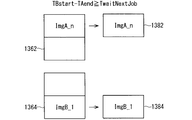
図3は、実施の形態1のプリンタを備える印刷システムにおけるジョブの保持状態を示すブロック図である。図4は、実施の形態1のプリンタにおけるジョブの受信タイミングを示すタイムチャートである。図5は、実施の形態1のプリンタにおいてジョブ間の画像の連結が行われた場合に得られる印刷物を示す模式図である。図6は、実施の形態1のプリンタにおいてジョブ間の画像の連結が行われない場合に得られる印刷物を示す模式図である。
1.8 Linking Images Between Jobs FIG. 3 is a block diagram illustrating a job holding state in a printing system including the printer according to the first embodiment. FIG. 4 is a time chart showing job reception timings in the printer of the first embodiment. FIG. 5 is a schematic diagram illustrating a printed matter obtained when images are combined between jobs in the printer according to the first embodiment. FIG. 6 is a schematic diagram illustrating a printed matter obtained when images are not linked between jobs in the printer according to the first embodiment.
図3に示されるように、ホストPC1022に備えられるメモリ1302には、ホストPC1022により生成されたがプリンタ1024に送信されていない画像データJobB_1,JobB_2,JobB_3,JobB_4およびJobB_5が一時保持され、画像データ生成部1102に備えられるメモリ1122には、ホストPC1022から受信したが印刷が行われていない画像データJobA_n-5,JobA_n-4,JobA_n-3,JobA_n-2,JobA_n-1およびJobA_nが一時保持されている。画像データJobB_1,JobB_2,JobB_3,JobB_4およびJobB_5は、ジョブJobBに含まれる。画像データJobA_n-5,JobA_n-4,JobA_n-3,JobA_n-2,JobA_n-1およびJobA_nは、ジョブJobAに含まれる。
As shown in FIG. 3, the
図3に示されるジョブの保持状態においては、ホストPC1022は、JobBに含まれる画像データJobB_1,JobB_2,JobB_3,JobB_4およびJobB_5を既に生成したが、ジョブJobBに含まれる残余の画像データをさらに生成している。図3に示されるジョブの保持状態においては、ジョブJobBの生成が完了していないため、ホストPC1022からプリンタ1024への画像データの転送が行われていない。
In the job holding state shown in FIG. 3, the
図3に示されるジョブの保持状態においては、プリンタ1024は、ジョブJobAに含まれる、6個の画像データJobA_n-5,JobA_n-4,JobA_n-3,JobA_n-2,JobA_n-1およびJobA_n以外のn−6個の画像データについて印刷中であり、残余の画像データJobA_n-5,JobA_n-4,JobA_n-3,JobA_n-2,JobA_n-1およびJobA_nを保持している。
In the job holding state shown in FIG. 3, the
画像データ生成部1102は、図4に示されるように、ジョブJobAに続いてジョブJobBを受信する。ジョブJobAが受信される場合は、ジョブJobAに含まれる画像データJobA_1,JobA_2,・・・,JobA_n-1,JobA_nが順次に受信される。ジョブJobBが受信される場合は、ジョブJobBに含まれる画像データJobB_1,JobB_2,・・・,JobB_n-1,JobB_nが順次に受信される。図3に示されるジョブの保持状態は、ジョブJobAにおいて最後に受信される画像データJobA_nの受信が終了した後であってジョブJobBにおいて最初に受信される画像データJobB_1の受信が開始される前のものである。画像データJobA_nおよびJobB_1は、それぞれ画像ImgA_nおよびImgB_1を表現する。画像ImgA_nおよびImgB_1の各々は、小判サイズを有する。
As illustrated in FIG. 4, the image
待機時間制御部1110は、画像データJobA_nの受信を時刻TAendに終了してから経過時間Tの計測を開始し、画像データJobA_nの受信を時刻TAendに終了してから画像データJobB_1の受信を時刻TBstartに開始するまでの時間TBstart-TAendが待機時間TwaitNextJobより短い場合は、インクシート面1182を1回使用して画像ImgA_nおよびImgB_1を連結して印刷するジョブ間の画像の連結が行われるように印刷機構1046を制御する。ジョブ間の画像の連結は、ジョブJobAに含まれる画像データJobA_1,JobA_2,・・・,JobA_n-1,JobA_nが奇数個の画像データである場合等のジョブ内の画像の連結からあぶれた画像データJobA_nが存在する場合に行われる。
The standby
ジョブ間の画像の連結が行われる場合は、インクシート1068が搬送され、インクシート面1182が間隙1142を通過している間に、間隙1142を通過しているインクシート面1182を使用して画像ImgA_nおよびImgB_1を含む1個の画面が印刷される。この場合は、インクシート面1182が間隙1142を通過した後にインクシート1068の巻き戻しが行われず、間隙1142を通過したインクシート面1182が間隙1142を再び通過することはなく、インクシート面1182が有する第1の領域1222,1242,1262および1282ならびに第2の領域1224,1244,1264および1284が使用される。巻き戻しが行われないことは、ダメージを受けたインクシート面1182を使用して印刷が行われることを抑制し、印刷の品位を向上させる。また、巻き戻しが行われないことは、巻き戻し、巻き戻しの後のプリンタ1024に備えられる構成物の復帰等に要する待ち時間をなくし、印刷に要する時間を短くする。第1の領域1222,1242,1262および1282ならびに第2の領域1224,1244,1264および1284が使用されることは、インクシート1068の一部が無駄になることを抑制し、印刷のコストを低下させる。
When the images are connected between jobs, the
図5に示されるように、画像ImgA_nおよびImgB_1を含む画面が印刷されたペーパー1322は、カット機構1080によりカットされる。これにより、画像ImgA_nが印刷された印刷物1342および画像ImgB_1が印刷された印刷物1344が得られる。印刷物1342および1344の各々は、小判サイズを有する。
As shown in FIG. 5, the
待機時間制御部1110は、経過時間Tが待機時間TwaitNextJobを超えた場合は、すなわち、時間TBstart-TAendが待機時間TwaitNextJobより長い場合は、ジョブ間の画像の連結が行われないように印刷機構1046を制御する。
When the elapsed time T exceeds the waiting time TwaitNextJob, that is, when the time TBstart-TAend is longer than the waiting time TwaitNextJob, the waiting
ジョブ間の画像の連結が行われない場合は、インクシート1068が搬送され、インクシート面1182である第1のインクシート面が間隙1142を通過している間に、間隙1142を通過している第1のインクシート面の第1の領域1222,1242,1262および1282を使用して画像ImgA_nのみを含む第1の画面が印刷される。
When the images are not connected between jobs, the
第1の画面の印刷において第1のインクシート面が大きなダメージを受けた場合は、インクシート1068がさらに搬送され、第1のインクシート面に続くインクシート面1182である第2のインクシート面が間隙1142を通過している間に、間隙1142を通過している第2のインクシート面の第2の領域1224,1244,1264および1284を使用して画像ImgB_1のみを含む1個の画面が印刷される。この場合は、第1のインクシート面が間隙1142を通過した後にインクシート1068の巻き戻しが行われず、間隙1142を通過した第1のインクシート面が間隙1142を再び通過することはないが、第1のインクシート面が有する第2の領域1224,1244,1264および1284が使用されない。
When the first ink sheet surface is greatly damaged in the printing of the first screen, the
第1の画面の印刷において第1のインクシート面が大きなダメージを受けていない場合は、インクシート1068の巻き戻しが行われ、第1のインクシート面が間隙1142を再び通過している間に、間隙1142を通過している第1のインクシート面の第2の領域1224,1244,1264および1284を使用して画像ImgB_1のみを含む第2の画面が印刷される。この場合は、第1のインクシート面が有する第1の領域1222,1242,1262および1282ならびに第2の領域1224,1244,1264および1284が使用されるが、第1のインクシート面が間隙1142を通過した後にインクシート1068の巻き戻しが行われ、間隙1142を通過した第1のインクシート面が間隙1142を再び通過する。
When the first ink sheet surface is not significantly damaged during the printing of the first screen, the
画像ImgA_nのみを含む画面が印刷されたペーパー1362からは、図6に示されるように、画像ImgA_nが印刷された印刷物1382が得られる。画像ImgB_1のみを含む画面が印刷されたペーパー1364からは、図6に示されるように、画像ImgB_1が印刷された印刷物1384が得られる。印刷物1382および1384の各々は、小判サイズを有する。
From a
第1のインクシート面が大きなダメージを受けたか否かは、画像ImgA_nの濃度に基づいて判定される。画像ImgA_nの濃度が基準より濃い場合は、第1のインクシート面が大きなダメージを受けたと判定される。第1のインクシート面が大きなダメージを受けたか否かが他の方法により判定されてもよい。 Whether or not the first ink sheet surface has been greatly damaged is determined based on the density of the image ImgA_n. When the density of the image ImgA_n is higher than the reference, it is determined that the first ink sheet surface has been damaged greatly. It may be determined by other methods whether or not the first ink sheet surface has undergone significant damage.
待機時間TwaitNextJobは、ユーザーが先行するジョブを生成する作業を行ってから後続するジョブを生成する作業を行うまでに要する時間に基づいて決定され、当該時間が長くなるほど長くされる。これにより、ジョブ内の画像の連結からあぶれた画像データJobA_nが存在する状況において、インクシート面1182を1回使用して画像ImgA_nおよびImgB_1を連結して印刷できる場合が多くなる。したがって、インクシートの種類を増やさずに、印刷の品位が低下することが抑制され、インクシート1068の一部が無駄になることが抑制され、印刷に要する時間が短くなり、印刷のコストが低下する。
The waiting time TwaitNextJob is determined based on the time required from the time when the user performs the work for generating the preceding job to the time for performing the work for generating the succeeding job, and becomes longer as the time becomes longer. As a result, in a situation where there is image data JobA_n blurred from the connection of images in the job, there are many cases where the images ImgA_n and ImgB_1 can be connected and printed using the
待機時間TwaitNextJobは、概ね分単位で決定されている。ただし、待機時間TwaitNextJobが分単位で決定されないことも許される。 The waiting time TwaitNextJob is generally determined in minutes. However, it is allowed that the waiting time TwaitNextJob is not determined in minutes.
待機時間TwaitNextJobは、待機時間Twaitと共通化されておらず、待機時間Twaitより長くなっている。待機時間TwaitNextJobが待機時間Twaitと共通化されてないのは、望ましい待機時間Twaitが印刷システム1000に依存しているのに対して、望ましい待機時間TwaitNextJobがユーザーに依存しているからである。待機時間TwaitNextJobが待機時間Twaitより長くなっているのは、画像データJob_1の受信が終了されてから画像データJob_2の受信が開始されるまでの時間は相対的に短いことが想定され、画像データJobA_nの受信が終了されてから画像データJobB_1の受信が開始されるまでの時間は相対的に長いことが想定されるからである。
The waiting time TwaitNextJob is not shared with the waiting time Twait, and is longer than the waiting time Twait. The reason why the waiting time TwaitNextJob is not shared with the waiting time Twait is that the desired waiting time Twait depends on the
2 実施の形態2
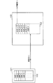
図7は、実施の形態2のプリンタを備える印刷システムを示すブロック図である。
2
FIG. 7 is a block diagram illustrating a printing system including the printer according to the second embodiment.
図7に示される印刷システム2000は、ホストPC2022およびプリンタ2024を備える。プリンタ2024は、印刷部2042および制御部2044を備える。制御部2044は、画像データ生成部2062、サーマルヘッド制御部2064、インクシート駆動制御部2066、ペーパー駆動制御部2068および待機時間制御部2070を備える。
A
印刷システム2000に備えられる印刷部2042、画像データ生成部2062、サーマルヘッド制御部2064、インクシート駆動制御部2066およびペーパー駆動制御部2068は、それぞれ、印刷システム1000に備えられる印刷部1042、画像データ生成部1102、サーマルヘッド制御部1104、インクシート駆動制御部1106およびペーパー駆動制御部1108と同様のものである。
The
印刷システム1000と印刷システム2000との相違は、印刷システム1000においては待機時間TwaitおよびTwaitNextJobが固定されているのに対して、印刷システム2000においては待機時間TwaitおよびTwaitNextJobを変更可能である点にある。以下では、当該相違をもたらす印刷システム2000の構成について専ら説明する。
The difference between the
ホストPC2022は、プリンタ制御用のソフトウェアを実行しプリンタ制御用のソフトウェアにしたがって動作することにより、ユーザーによる待機時間TwaitおよびTwaitNextJobの設定を受け付け、当該設定の内容を示す待機時間設定データを生成し、画像データおよび待機時間設定データを含むジョブをプリンタ2024に送信する。
The
複数個の画像データが送信される場合は、複数個の画像データの各々について待機時間Twaitの設定が行われる。2個以上の画像データについて共通する待機時間Twaitの設定が行われてもよい。共通する待機時間Twaitの設定が行われる2個以上の画像データは、ホストPC2022の状態、ジョブの生成作業の状態等に応じて、使い勝手が向上するように選択される。
When a plurality of image data are transmitted, a waiting time Twait is set for each of the plurality of image data. A common waiting time Twait may be set for two or more pieces of image data. Two or more pieces of image data for which a common waiting time Twait is set are selected so as to improve usability according to the state of the
複数個のジョブが送信される場合は、複数個のジョブの各々について待機時間TwaitNextJobの設定が行われる。2個以上のジョブについて共通する待機時間TwaitNextJobの設定が行われてもよい。共通する待機時間TwaitNextJobの設定が行われる2個以上のジョブは、ホストPC2022の状態、ジョブの生成作業の状態等に応じて、使い勝手が向上するように選択される。
When a plurality of jobs are transmitted, the waiting time TwaitNextJob is set for each of the plurality of jobs. A common waiting time TwaitNextJob may be set for two or more jobs. Two or more jobs for which the common waiting time TwaitNextJob is set are selected so as to improve usability according to the state of the
待機時間制御部2070は、受信したジョブに含まれる待機時間設定データに基づいて、待機時間TwaitおよびTwaitNextJobを変更する。これにより、待機時間TwaitおよびTwaitNextJobがユーザーによる設定に応じて変更される。待機時間TwaitおよびTwaitNextJobが待機時間設定データ以外に基づいて変更されてもよい。例えば、プリンタ2024が待機時間TwaitおよびTwaitNextJobの設定を受け付け、待機時間制御部2070が当該設定に基づいて待機時間TwaitおよびTwaitNextJobを変更してもよい。
The standby time control unit 2070 changes the standby times Twait and TwaitNextJob based on the standby time setting data included in the received job. Thereby, the waiting times Twait and TwaitNextJob are changed according to the setting by the user. The waiting times Twait and TwaitNextJob may be changed based on data other than the waiting time setting data. For example, the
待機時間Twaitの設定は、設定の目的およびホストPC2022の状態に応じて行われる。待機時間TwaitNextJobの設定は、設定の目的およびジョブの生成作業の状態に応じて行われる。
The setting of the waiting time Twait is performed in accordance with the purpose of the setting and the state of the
図8は、実施の形態2のプリンタを備える印刷システムにおける待機時間Twaitの設定例を示す。 FIG. 8 shows a setting example of the waiting time Twait in the printing system including the printer according to the second embodiment.
図8に示される待機時間Twaitの設定例においては、設定の目的が画像を1個ずつ印刷することにある場合は、待機時間Twaitが0秒になるように待機時間Twaitの設定が行われる。これにより、先行する画像データの受信が行われた場合に、後続する画像データの受信を待つことなく先行する画像データにより表現される画像が印刷され、インクシート2082の巻き戻し等が行われる。すなわち、ジョブ内の画像の連結が行われず、画像が印刷されるごとにインクシート2082の巻き戻し等が行われる。
In the setting example of the waiting time Twait shown in FIG. 8, when the purpose of setting is to print one image at a time, the waiting time Twait is set so that the waiting time Twait becomes 0 seconds. As a result, when the preceding image data is received, the image represented by the preceding image data is printed without waiting for the subsequent image data to be received, and the
設定の目的がジョブ内の画像を連結して印刷することにあり画像データの転送速度が速い場合は、待機時間Twaitが5秒になるように待機時間Twaitの設定が行われる。これにより、先行する画像データの受信を終了してから5秒以内に後続する画像データの受信を開始できるような転送速度で画像データが転送される場合に、ジョブ内の画像の連結が行われる。 If the purpose of the setting is to link and print the images in the job and the transfer rate of the image data is high, the waiting time Twait is set so that the waiting time Twait is 5 seconds. As a result, when the image data is transferred at such a transfer speed that reception of the subsequent image data can be started within 5 seconds after the reception of the preceding image data is completed, the images in the job are connected. .
設定の目的がジョブ内の画像を連結して印刷することにあり画像データの転送速度が遅い場合は、待機時間Twaitが100秒になるように待機時間Twaitの設定が行われる。これにより、先行する画像データの受信を終了してから100秒以内に後続する画像データの受信を開始できるような転送速度で画像データが転送される場合に、ジョブ内の画像の連結が行われる。 If the purpose of setting is to link and print the images in the job and the transfer speed of the image data is slow, the waiting time Twait is set so that the waiting time Twait is 100 seconds. As a result, when the image data is transferred at such a transfer speed that the reception of the subsequent image data can be started within 100 seconds after the reception of the preceding image data is completed, the images in the job are connected. .
画像データの転送速度は、ホストPC2022の状態によって変化する。ホストPC2022の仕様が標準的なものでありホストPCが高負荷の処理を行っていない場合は、画像データの転送速度が速くなる。ホストPC2022の仕様が標準的なものより低いものである場合またはホストPC2022が高負荷の処理を行っている場合は、画像データの転送速度が遅くなる。
The image data transfer speed varies depending on the state of the
より一般的には、設定の目的が画像を1個ずつ印刷することにある場合は、待機時間Twaitが相対的に短くなるように待機時間Twaitの設定が行われ、設定の目的がジョブ内の画像を連結して印刷することにある場合は、待機時間Twaitが相対的に長くなるように待機時間Twaitの設定が行われる。また、画像データの転送速度が速くなるほど、待機時間Twaitが短くなるように待機時間Twaitの設定が行われる。 More generally, when the purpose of setting is to print one image at a time, the waiting time Twait is set so that the waiting time Twait is relatively short. When the images are to be connected and printed, the waiting time Twait is set so that the waiting time Twait is relatively long. Further, the waiting time Twait is set so that the waiting time Twait becomes shorter as the transfer rate of the image data becomes faster.
図8に示される待機時間TwaitNextJobの設定例においては、設定の目的がジョブごとに区切って画像を印刷することにある場合は、待機時間TwaitNextJobが0秒になるように待機時間TwaitNextJobの設定が行われる。これにより、先行するジョブに含まれる最後の画像データの受信が行われた場合に、後続するジョブに含まれる最初の画像データの受信を待つことなく先行するジョブに含まれる最後の画像データにより表現される画像が印刷され、インクシート2082の巻き戻し等が行われる。すなわち、ジョブ間の画像の連結が行われず、ジョブごとにインクシート2082の巻き戻し等が行われる。この場合は、先行するジョブに含まれる画像データにより表現される画像と後続するジョブに含まれる画像データにより表現される画像とが混じることなく印刷される。
In the setting example of the waiting time TwaitNextJob shown in FIG. 8, when the purpose of the setting is to print an image divided for each job, the waiting time TwaitNextJob is set so that the waiting time TwaitNextJob becomes 0 seconds. Is called. Thus, when the last image data included in the preceding job is received, it is expressed by the last image data included in the preceding job without waiting for the reception of the first image data included in the succeeding job. The image to be printed is printed, and the
設定の目的がジョブ間の画像を連結して印刷することにありジョブの生成作業が単純で時間がかからない場合は、待機時間TwaitNextJobが30秒になるように待機時間TwaitNextJobの設定が行われる。これにより、先行するジョブに含まれる最後の画像データの受信を終了してから30秒以内に後続するジョブに含まれる最初の画像データの受信を開始できるような生成速度でジョブが生成される場合に、ジョブ間の画像の連結が行われる。 If the purpose of the setting is to link and print images between jobs and the job generation is simple and does not take much time, the waiting time TwaitNextJob is set so that the waiting time TwaitNextJob is 30 seconds. When a job is generated at such a generation speed that reception of the first image data included in the succeeding job can be started within 30 seconds after reception of the last image data included in the preceding job is completed. In addition, images are linked between jobs.
設定の目的がジョブ間の画像を連結して印刷することにありジョブの生成作業が複雑で時間がかかる場合は、待機時間TwaitNextJobが180秒になるように待機時間TwaitNextJobの設定が行われる。これにより、先行するジョブに含まれる最後の画像データの受信を終了してから180秒以内に後続するジョブに含まれる最初の画像データの受信を開始できるような生成速度でジョブが生成される場合に、ジョブ間の画像の連結が行われる。ジョブの生成作業が複雑で時間がかかる場合には、編集作業が必要である場合等がある。 If the purpose of the setting is to link and print images between jobs and the job generation work is complex and time consuming, the waiting time TwaitNextJob is set so that the waiting time TwaitNextJob is 180 seconds. When a job is generated at such a generation speed that reception of the first image data included in the succeeding job can be started within 180 seconds after reception of the last image data included in the preceding job is completed. In addition, images are linked between jobs. When job generation work is complicated and takes time, editing work may be necessary.
より一般的には、設定の目的がジョブごとに区切って画像を印刷することにある場合は、待機時間TwaitNextJobが相対的に短くなるように待機時間TwaitNextJobの設定が行われ、設定の目的がジョブ間の画像を連結して印刷することにある場合は、待機時間TwaitNextJobが相対的に長くなるように待機時間TwaitNextJobの設定が行われる。また、ジョブの生成作業が単純で時間がかからなくなるほど待機時間TwaitNextJobが短くなるように待機時間TwaitNextJobの設定が行われる。 More generally, when the purpose of the setting is to print an image by dividing each job, the waiting time TwaitNextJob is set so that the waiting time TwaitNextJob is relatively short, and the setting purpose is the job In the case where printing is performed by connecting images in between, the waiting time TwaitNextJob is set so that the waiting time TwaitNextJob is relatively long. In addition, the waiting time TwaitNextJob is set so that the waiting time TwaitNextJob becomes shorter as the job generation is simple and takes less time.
実施の形態2においても、実施の形態1と同様に、印刷の品位が低下することが抑制され、インクシート2082の一部が無駄になることが抑制され、印刷に要する時間が短くなり、印刷のコストが低下する。加えて、実施の形態2においては、設定の目的、ホストPC2022の状態およびジョブの生成作業の状態に適合する印刷が行われ、印刷システムの使い勝手が向上する。
In the second embodiment as well, as in the first embodiment, it is possible to suppress the printing quality from being deteriorated, to prevent a part of the
3 実施の形態3
図9は、実施の形態3のプリンタを備える印刷システムを示すブロック図である。
3
FIG. 9 is a block diagram illustrating a printing system including the printer according to the third embodiment.
図9に示される印刷システム3000は、ホストPC3022およびプリンタ3024を備える。プリンタ3024は、印刷部3042および制御部3044を備える。制御部3044は、画像データ生成部3062、サーマルヘッド制御部3064、インクシート駆動制御部3066、ペーパー駆動制御部3068、待機時間制御部3070およびジョブ状態解析部3072を備える。
A
印刷システム3000に備えられる印刷部3042、画像データ生成部3062、サーマルヘッド制御部3064、インクシート駆動制御部3066およびペーパー駆動制御部3068は、それぞれ、印刷システム2000に備えられる印刷部2042、画像データ生成部2062、サーマルヘッド制御部2064、インクシート駆動制御部2066およびペーパー駆動制御部2068と同様のものである。
A
印刷システム2000と印刷システム3000との相違は、印刷システム2000においては、受信したジョブに含まれる待機時間設定データに基づいて待機時間TwaitおよびTwaitNextJobの設定が行われるのに対して、印刷システム3000においては受信したジョブに待機時間設定データが含まれず受信したジョブの状態の解析結果に基づいて待機時間TwaitおよびTwaitNextJobの設定が行われる点にある。以下では、当該相違をもたらす印刷システム3000の構成について専ら説明する。
The difference between the
ジョブ状態解析部3072は、受信したジョブの状態を解析することにより解析結果を取得し、取得した解析結果に基づいて待機時間TwaitおよびTwaitNextJobの設定を行う。
The job
待機時間制御部3070は、当該設定に基づいて待機時間TwaitおよびTwaitNextJobを変更する。
The standby
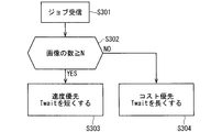
図10および11の各々は、実施の形態3のプリンタにおけるジョブの状態の解析および待機時間Twaitの設定のための処理を示すフローチャートである。 Each of FIGS. 10 and 11 is a flowchart illustrating processing for analyzing the job state and setting the waiting time Twait in the printer of the third embodiment.
図10に示されるステップS301においては、ホストPC3022から送信されてくるジョブが受信される。
In step S301 shown in FIG. 10, a job transmitted from the
続くステップS302においては、受信したジョブに含まれる画像データの数、すなわち、印刷しなければならない画像の数がN個以上であるか否かが判定される。Nは、正の整数である。画像の数がN個以上である場合は、処理がステップS303へ進む。そうでない場合は、処理がステップS304へ進む。 In a succeeding step S302, it is determined whether or not the number of image data included in the received job, that is, the number of images to be printed is N or more. N is a positive integer. If the number of images is N or more, the process proceeds to step S303. Otherwise, the process proceeds to step S304.
ステップS303においては、待機時間Twaitが相対的に短くなるように待機時間Twaitの設定が行われ、ステップS304においては待機時間Twaitが相対的に長くなるように待機時間Twaitの設定が行われる。 In step S303, the standby time Twait is set so that the standby time Twait is relatively short. In step S304, the standby time Twait is set so that the standby time Twait is relatively long.
これにより、印刷しなければならない画像が多い場合は、待機時間Twaitが相対的に短くなるように待機時間Twaitの設定が行われ、印刷の速度を速くすることが優先される。 Accordingly, when there are many images that need to be printed, the standby time Twait is set so that the standby time Twait is relatively short, and priority is given to increasing the printing speed.
一方、印刷しなければならない画像が少ない場合は、待機時間Twaitが相対的に長くなるように待機時間Twaitの設定が行われ、複数個の画像を連結して印刷し印刷のコストを低下させることが優先される。 On the other hand, when there are few images that need to be printed, the waiting time Twait is set so that the waiting time Twait is relatively long, and a plurality of images are connected and printed to reduce the printing cost. Takes precedence.
待機時間Twaitの設定を行うアルゴリズムが変更されてもよい。例えば、印刷しなければならない画像の数が多くなるほど待機時間Twaitが短くなるように数式また数値テーブルを用いて印刷しなければならない画像の数から待機時間Twaitの設定値が算出されてもよい。 The algorithm for setting the waiting time Twait may be changed. For example, the set value of the waiting time Twait may be calculated from the number of images that need to be printed using a mathematical formula or a numerical table so that the waiting time Twait becomes shorter as the number of images that need to be printed increases.
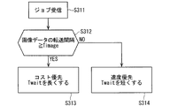
図11に示されるステップS311においては、ホストPC3022から送信されてくるジョブが受信される。
In step S311 shown in FIG. 11, a job transmitted from the
続くステップS312においては、受信したジョブに含まれる画像データの転送間隔が判定値Timage以上であるか否かが判定される。画像データの転送間隔が判定値Timage以上である場合は、処理がステップS313へ進む。そうでない場合は、処理がステップS314へ進む。 In the subsequent step S312, it is determined whether or not the transfer interval of the image data included in the received job is equal to or greater than the determination value Timage. If the image data transfer interval is greater than or equal to the determination value Timage, the process proceeds to step S313. Otherwise, the process proceeds to step S314.
ステップS313においては、待機時間Twaitが相対的に長くなるように待機時間Twaitの設定が行われ、ステップS314においては待機時間Twaitが相対的に短くなるように待機時間Twaitの設定が行われる。 In step S313, the standby time Twait is set so that the standby time Twait is relatively long. In step S314, the standby time Twait is set so that the standby time Twait is relatively short.
これにより、受信したジョブに含まれる画像データの転送間隔が短く転送速度が速い場合は、待機時間Twaitが相対的に短くなるように待機時間Twaitの設定が行われ、印刷の速度を速くすることが優先される。 As a result, when the transfer interval of image data included in the received job is short and the transfer speed is fast, the waiting time Twait is set so that the waiting time Twait is relatively short, and the printing speed is increased. Takes precedence.
一方、受信したジョブに含まれる画像データの転送間隔が長く転送速度が遅い場合は、待機時間Twaitが相対的に長くなるように待機時間Twaitの設定が行われ、印刷のコストを低下させることが優先される。これにより、複数の画像を連結して印刷できる場合が増え、印刷の品位が低下することが抑制され、インクシート3082の一部が無駄になることが抑制される。
On the other hand, if the transfer interval of image data included in the received job is long and the transfer speed is slow, the waiting time Twait is set so that the waiting time Twait is relatively long, which may reduce the printing cost. have priority. As a result, it is possible to increase the number of cases where a plurality of images can be connected and to print, and to prevent the printing quality from being deteriorated, and to prevent a part of the
待機時間Twaitの設定を行うアルゴリズムが変更されてもよい。例えば、画像データの転送間隔が長くなるほど待機時間Twaitが長くなるように数式また数値テーブルを用いて画像データの転送間隔から待機時間Twaitの設定値が算出されてもよい。 The algorithm for setting the waiting time Twait may be changed. For example, the set value of the waiting time Twait may be calculated from the image data transfer interval using a mathematical formula or a numerical table so that the waiting time Twait becomes longer as the image data transfer interval becomes longer.
図12および13は、実施の形態3のプリンタにおけるジョブの状態の解析および待機時間TwaitNextJobの設定のための処理を示すフローチャートである。 12 and 13 are flowcharts showing processing for analyzing the job status and setting the waiting time TwaitNextJob in the printer of the third embodiment.
図12に示されるステップS321においては、ホストPC3022から送信されてくるジョブが受信される。
In step S321 shown in FIG. 12, a job transmitted from the
続くステップS322においては、1時間あたりに転送されてくるジョブの数がN個以上であるか否かが判定される。Nは、正の整数である。1時間あたりに転送されてくるジョブの数がN個以上である場合は、処理がステップS323へ進む。そうでない場合は、処理がステップS324へ進む。 In the subsequent step S322, it is determined whether or not the number of jobs transferred per hour is N or more. N is a positive integer. If the number of jobs transferred per hour is N or more, the process proceeds to step S323. Otherwise, the process proceeds to step S324.
1時間あたりに転送されてくるジョブの数は、ジョブを生成する作業が長時間に渡って継続されておりジョブの転送が長時間にわたって継続されている場合は、現在の時刻の1時間前から現在の時刻までに転送されてきたジョブの数であり、ジョブを生成する作業が開始されてから間もなくジョブの転送が開始されてから間もない場合は、過去の作業履歴すなわち過去の転送履歴に基づくジョブの数等である。1時間あたりに転送されてくるジョブの数に代えて、1時間より長いまたは短い特定の時間あたりに転送されてくるジョブの数が使用されてもよい。特定の時間は、分単位、日単位、週単位等で決定され、ジョブの生成作業に適合するように決定される。 The number of jobs transferred per hour is determined from the hour before the current time when the job generation operation is continued for a long time and the job transfer is continued for a long time. This is the number of jobs that have been transferred up to the current time. If the job transfer has started soon after the job generation has started, the past work history, that is, the past transfer history The number of jobs based, etc. Instead of the number of jobs transferred per hour, the number of jobs transferred per specific time longer or shorter than one hour may be used. The specific time is determined in units of minutes, days, weeks, or the like, and is determined so as to match the job generation work.
ステップS323においては、待機時間TwaitNextJobが相対的に短くなるように待機時間TwaitNextJobの設定が行われ、ステップS324においては、待機時間TwaitNextJobが相対的に長くなるように待機時間TwaitNextJobの設定が行われる。 In step S323, the waiting time TwaitNextJob is set so that the waiting time TwaitNextJob is relatively short. In step S324, the waiting time TwaitNextJob is set so that the waiting time TwaitNextJob is relatively long.
これにより、1時間あたりに転送されてくるジョブの数が多く印刷しなければならない画像が多い場合は、待機時間TwaitNextJobが相対的に短くなるように待機時間TwaitNextJobの設定が行われ、印刷の速度を速くすることが優先される。 As a result, if the number of jobs transferred per hour is large and there are many images that must be printed, the waiting time TwaitNextJob is set so that the waiting time TwaitNextJob is relatively short, and the printing speed Priority is given to speeding up.
一方、1時間あたりに転送されてくるジョブの数が少なく印刷しなければならない画像が少ない場合は、待機時間TwaitNextJobが相対的に長くなるように待機時間TwaitNextJobの設定が行われ、複数個の画像を連結して印刷し印刷のコストを低下させることが優先される。 On the other hand, if the number of jobs transferred per hour is small and there are few images that need to be printed, the wait time TwaitNextJob is set so that the wait time TwaitNextJob is relatively long. Priority is given to printing by concatenating and reducing printing costs.
図13に示されるステップS331においては、ホストPC3022から送信されてくるジョブが受信される。
In step S331 shown in FIG. 13, a job transmitted from the
続くステップS332においては、ジョブの転送間隔が判定値Tjob以上であるか否かが判定される。ジョブの転送間隔が判定値Tjob以上である場合は、処理がステップS333へ進む。そうでない場合は、処理がステップS334へ進む。 In the subsequent step S332, it is determined whether or not the job transfer interval is equal to or greater than a determination value Tjob. If the job transfer interval is equal to or greater than the determination value Tjob, the process proceeds to step S333. Otherwise, the process proceeds to step S334.
ステップS333においては、待機時間TwaitNextJobが相対的に長くなるように待機時間TwaitNextJobの設定が行われ、ステップS334においては待機時間TwaitNextJobが相対的に短くなるように待機時間TwaitNextJobの設定が行われる。 In step S333, the waiting time TwaitNextJob is set so that the waiting time TwaitNextJob is relatively long. In step S334, the waiting time TwaitNextJob is set so that the waiting time TwaitNextJob is relatively short.
これにより、ジョブの転送間隔が短く転送速度が速い場合は、待機時間TwaitNextJobが相対的に短くなるように待機時間TwaitNextJobの設定が行われ、印刷の速度を速くすることが優先される。 Thus, when the job transfer interval is short and the transfer speed is high, the standby time TwaitNextJob is set so that the standby time TwaitNextJob is relatively short, and priority is given to increasing the printing speed.
一方、ジョブの転送間隔が長く転送速度が遅い場合は、待機時間TwaitNextJobが相対的に長くなるように待機時間TwaitNextJobの設定が行われ、印刷のコストを低下させることが優先される。これにより、複数の画像が連結して印刷される場合が増え、印刷の品位が低下することが抑制され、インクシート3082の一部が無駄になることが抑制される。
On the other hand, when the job transfer interval is long and the transfer speed is low, the standby time TwaitNextJob is set so that the standby time TwaitNextJob is relatively long, and priority is given to reducing the printing cost. As a result, the case where a plurality of images are connected and printed is increased, the deterioration of the printing quality is suppressed, and the part of the
実施の形態3においても、実施の形態1と同様に、印刷の品位が低下することが抑制され、インクシート3082の一部が無駄になることが抑制され、印刷に要する時間が短くなり、印刷のコストが低下する。加えて、実施の形態3においては、ユーザーに待機時間TwaitおよびTwaitNextJobの設定を行わせることなく、ジョブの状態に応じた待機時間TwaitおよびTwaitNextJobの設定が自動的に行われ、ジョブの状態に適合する印刷が行われ、印刷システムの使い勝手が向上する。
In the third embodiment, as in the first embodiment, it is possible to suppress the deterioration of printing quality, to suppress a part of the
4 実施の形態4
図14は、実施の形態4のプリンタを備える印刷システムを示すブロック図である。
4
FIG. 14 is a block diagram illustrating a printing system including the printer according to the fourth embodiment.
図14に示される印刷システム4000は、ホストPC4022およびプリンタ4024を備える。プリンタ4024は、印刷部4042および制御部4044を備える。制御部4044は、画像データ生成部4062、サーマルヘッド制御部4064、インクシート駆動制御部4066、ペーパー駆動制御部4068、待機時間制御部4070、ジョブ状態解析部4072およびジョブパターン登録部4074を備える。
A
印刷システム4000に備えられる印刷部4042、画像データ生成部4062、サーマルヘッド制御部4064、インクシート駆動制御部4066、ペーパー駆動制御部4068および待機時間制御部4070は、それぞれ、印刷システム3000に備えられる印刷部3042、画像データ生成部3062、サーマルヘッド制御部3064、インクシート駆動制御部3066、ペーパー駆動制御部3068および待機時間制御部3070と同様のものである。
The
印刷システム3000と印刷システム4000との相違は、印刷システム3000においては、受信したジョブの状態の解析結果に基づいて待機時間TwaitおよびTwaitNextJobの設定が行われるのに対して、印刷システム4000においては、複数個のジョブパターンから選択されたジョブパターンおよび受信したジョブの状態の解析結果に基づいて待機時間TwaitおよびTwaitNextJobの設定が行われる点にある。以下では、当該相違をもたらす印刷システム4000の構成について専ら説明する。
The difference between the
ジョブパターン登録部4074には、ジョブパターンA,B,CおよびDが登録される。ジョブパターンA,B,CおよびDは、ユーザーが過去に行った印刷を類型分けしたものである。ジョブパターンAは、各々が多数個の画像データを含む複数のジョブについて連続的に印刷が行われるジョブパターンである。ジョブパターンBは、各々が少数個の画像データを含む複数のジョブについて連続的に印刷が行われるジョブパターンである。ジョブパターンCは、各々が多数個の画像データを含む複数のジョブについて間欠的に印刷が行われるジョブパターンである。ジョブパターンDは、各々が少数個の画像データを含む複数のジョブについて間欠的に印刷が行われるジョブパターンである。したがって、ジョブパターンA,B,CおよびDは、ジョブに含まれる画像データの数および印刷の実行の連続性の2個の項目に関して互いに異なる。当該2個の項目が他の少なくとも1個の項目に置き換えられてもよい。4個のジョブパターンA,B,CおよびDが3個以下または5個以上のジョブパターンに置き換えられてもよい。
Job patterns A, B, C, and D are registered in the job
ジョブパターン登録部4074は、ジョブパターン設定データをホストPC4022から受信する。ジョブパターン設定データは、ジョブパターンA,B,CおよびDから選択されたジョブパターンを示す。したがって、ジョブパターン登録部4074は、ジョブパターン設定データをホストPC4022から受信することにより、選択されたジョブパターンを特定する。ジョブパターン設定データの受信以外により選択されたジョブパターンが特定されてもよい。例えば、プリンタ4024がジョブパターンの設定を受け付け、当該設定に基づいて選択されたジョブパターンが特定されてもよい。
The job
ジョブ状態解析部4072は、選択されたジョブパターンおよび受信したジョブの状態を解析することにより取得される解析結果に基づいて、待機時間TwaitおよびTwaitNextJobの設定を行う。受信したジョブの状態の解析については、実施の形態3と同様である。
The job
ホストPC4022は、プリンタ制御用のソフトウェアを実行しプリンタ制御用のソフトウェアにしたがって動作することにより、ジョブパターンの設定を受け付け、ジョブパターンA,B,CおよびDから選択されたジョブパターンを示すジョブパターン設定データを生成し、画像データおよびジョブパターン設定データを含むジョブをプリンタ4024に送信する。
The host PC 4022 executes the printer control software and operates according to the printer control software, thereby accepting the setting of the job pattern and indicating the job pattern selected from the job patterns A, B, C, and D. Setting data is generated, and a job including image data and job pattern setting data is transmitted to the
図15は、実施の形態4のプリンタを備える印刷システムにおける選択されたジョブパターンを特定するための処理を示すフローチャートである。 FIG. 15 is a flowchart illustrating processing for specifying a selected job pattern in a printing system including the printer according to the fourth embodiment.
図15に示されるステップS401においては、作業が開始される。 In step S401 shown in FIG. 15, the work is started.
続くステップS402においては、ホストPC4022がジョブパターンの設定を受け付ける。当該設定においてジョブパターンAが選択された場合は、ステップS403において、ジョブパターンAが選択されたことを示すジョブパターン設定データがホストPC4022からプリンタ4024へ送信される。当該設定においてジョブパターンBが選択された場合は、ステップS404において、ジョブパターンBが選択されたことを示すジョブパターン設定データがホストPC4022からプリンタ4024へ送信される。当該設定においてジョブパターンCが選択された場合は、ステップS405において、ジョブパターンCが選択されたことを示すジョブパターン設定データがホストPC4022からプリンタ4024へ送信される。当該設定においてジョブパターンDが選択された場合は、ステップS406において、ジョブパターンDが選択されたことを示すジョブパターン設定データがホストPC4022からプリンタ4024へ送信される。
In the subsequent step S402, the host PC 4022 accepts a job pattern setting. If the job pattern A is selected in the setting, job pattern setting data indicating that the job pattern A is selected is transmitted from the host PC 4022 to the
実施の形態4においても、実施の形態1と同様に、印刷の品位が低下することが抑制され、インクシート4082の一部が無駄になることが抑制され、印刷に要する時間が短くなり、印刷のコストが低下する。加えて、実施の形態4においては、ユーザーに待機時間TwaitおよびTwaitNextJobの設定を行わせることなく、ジョブの状態に応じた待機時間TwaitおよびTwaitNextJobの設定が自動的に行われ、ジョブの状態に適合する印刷が行われ、印刷システムの使い勝手が向上する。選択されたジョブパターンが待機時間TwaitおよびTwaitNextJobの設定の基礎になることは、簡単な操作でジョブの状態により適合する印刷が行われるようにすることに寄与する。
In the fourth embodiment as well, as in the first embodiment, it is possible to suppress the printing quality from being lowered, to prevent a part of the
なお、本発明は、その発明の範囲内において、各実施の形態を自由に組み合わせたり、各実施の形態を適宜、変形、省略することが可能である。 It should be noted that the present invention can be freely combined with each other within the scope of the invention, and each embodiment can be appropriately modified or omitted.
1000,2000,3000,4000 印刷システム、1024,2024,3024,4024 プリンタ、1042,2042,3042,4042 印刷部、1044,2044,3044,4044 制御部、1182 インクシート面。 1000, 2000, 3000, 4000 printing system, 1024, 2024, 3024, 4024 printer, 1042, 2042, 3042, 4042 printing unit, 1044, 2044, 3044, 4044 control unit, 1182 ink sheet surface.
Claims (8)
(1)前記少なくとも1個のジョブが第1の画像データおよび第2の画像データを含み、前記印刷機構が前記第1の画像データに続いて前記第2の画像データを受信し、前記第1の画像データの受信が終了されてから前記第2の画像データの受信が開始されるまでの第1の時間が第1の待機時間より短い場合は、前記第1の画像データにより表現され前記第1のサイズより小さい第2のサイズを有する第1の画像および前記第2の画像データにより表現され前記第2のサイズを有する第2の画像を前記インクシート面を1回使用して連結して印刷する第1の連結が行われるように前記印刷機構を制御し、(2)前記第1の時間が前記第1の待機時間より長い場合は、前記第1の連結が行われないように前記印刷機構を制御し、(3)前記少なくとも1個のジョブが第1のジョブおよび第2のジョブを含み、前記印刷機構が前記第1のジョブに続いて前記第2のジョブを受信し、前記第1のジョブが第3の画像データを含み、前記第2のジョブが第4の画像データを含み、前記印刷機構が前記第1のジョブにおいて前記第3の画像データを最後に受信し前記第2のジョブにおいて前記第4の画像データを最初に受信し、前記第3の画像データの受信が終了されてから前記第4の受信データの受信が開始されるまでの第2の時間が第2の待機時間より短い場合は、前記第3の画像データにより表現され前記第2のサイズを有する第3の画像および前記第4の画像データにより表現され前記第2のサイズを有する第4の画像を前記インクシート面を1回使用して連結して印刷する第2の連結が行われるように前記印刷機構を制御し、(4)前記第2の時間が前記第2の待機時間より長い場合は、前記第2の連結が行われないように前記印刷機構を制御する待機時間制御部と、
を備えるプリンタ。 A printing mechanism for receiving at least one job and performing printing for the at least one job using an ink sheet having an ink sheet surface used to print a screen having a first size;
(1) The at least one job includes first image data and second image data, and the printing mechanism receives the second image data following the first image data. If the first time from the end of the reception of the second image data to the start of the reception of the second image data is shorter than the first standby time, the first image data is represented by the first image data. A first image having a second size smaller than one and a second image represented by the second image data and having the second size are connected using the ink sheet surface once. Controlling the printing mechanism so that the first connection for printing is performed; and (2) if the first time is longer than the first waiting time, the first connection is not performed. Controlling the printing mechanism, (3) At least one job includes a first job and a second job, the printing mechanism receives the second job following the first job, and the first job receives third image data. The second job includes fourth image data, and the printing mechanism last receives the third image data in the first job, and the fourth image data in the second job. Is received for the first time, and when the second time from the end of reception of the third image data to the start of reception of the fourth reception data is shorter than the second standby time, the second The ink sheet surface is used once for the third image having the second size expressed by the image data 3 and the fourth image having the second size expressed by the fourth image data. Second series to print (4) When the second time is longer than the second waiting time, the printing mechanism is controlled so that the second connection is not performed. A time control unit;
Printer with.
請求項1のプリンタ。 The printer according to claim 1, wherein the standby time control unit can change the first standby time and the second standby time.
をさらに備え、
前記待機時間制御部は、前記設定に基づいて前記第1の待機時間および前記第2の待機時間を変更する
請求項2のプリンタ。 A job status analysis unit that obtains an analysis result by analyzing the at least one job and sets the first waiting time and the second waiting time based on the analysis result;
The printer according to claim 2, wherein the standby time control unit changes the first standby time and the second standby time based on the setting.
をさらに備え、
前記ジョブ状態解析部は、前記ジョブパターンおよび前記解析結果に基づいて前記第1の待機時間および前記第2の待機時間の設定を行う
請求項3のプリンタ。 A plurality of job patterns are registered, and further includes a job pattern registration unit for specifying a job pattern selected from the plurality of job patterns,
The printer according to claim 3, wherein the job status analysis unit sets the first standby time and the second standby time based on the job pattern and the analysis result.
b) 少なくとも1個のジョブを受信する工程と、
c) 前記少なくとも1個のジョブが第1の画像データおよび第2の画像データを含み、前記第1の画像データに続いて前記第2の画像データが受信され、前記第1の画像データの受信が終了されてから前記第2の画像データの受信が開始されるまでの第1の時間が第1の待機時間より短い場合に、前記第1の画像データにより表現され前記第1のサイズより小さい第2のサイズを有する第1の画像および前記第2の画像データにより表現され前記第2のサイズを有する第2の画像を前記インクシート面を1回使用して連結して印刷する第1の連結が行われるように前記インクシートを使用して前記少なくとも1個のジョブについて印刷を行う工程と、
d) 前記第1の時間が前記第1の待機時間より長い場合に、前記第1の連結が行われないように前記インクシートを使用して前記少なくとも1個のジョブについて印刷を行う工程と、
e) 前記少なくとも1個のジョブが第1のジョブおよび第2のジョブを含み、前記第1のジョブに続いて前記第2のジョブが受信され、前記第1のジョブが第3の画像データを含み、前記第2のジョブが第4の画像データを含み、前記第1のジョブにおいて前記第3の画像データが最後に受信され前記第2のジョブにおいて前記第4の画像データが最初に受信され、前記第3の画像データの受信が終了されてから前記第4の受信データの受信が開始されるまでの第2の時間が第2の待機時間より短い場合に、前記第3の画像データにより表現され前記第2のサイズを有する第3の画像および前記第4の画像データにより表現され前記第2のサイズを有する第4の画像を前記インクシート面を1回使用して連結して印刷する第2の連結が行われるように前記インクシートを使用して前記少なくとも1個のジョブについて印刷を行う工程と、
f) 前記第2の時間が前記第2の待機時間より長い場合に、前記第2の連結が行われないように前記インクシートを使用して前記少なくとも1個のジョブについて印刷を行う工程と、
を備える印刷方法。 a) preparing an ink sheet having an ink sheet surface used to print a screen having a first size;
b) receiving at least one job;
c) The at least one job includes first image data and second image data, the second image data is received following the first image data, and the first image data is received. When the first time from when the second image data is received to when reception of the second image data is started is shorter than the first standby time, the first image data is expressed and is smaller than the first size. A first image having a second size and a second image represented by the second image data and having the second size are connected and printed using the ink sheet surface once. Printing for the at least one job using the ink sheet to be connected; and
d) printing the at least one job using the ink sheet so that the first connection is not performed when the first time is longer than the first waiting time;
e) The at least one job includes a first job and a second job, the second job is received following the first job, and the first job receives third image data. The second job includes fourth image data, the third image data is received last in the first job, and the fourth image data is received first in the second job. When the second time from the end of reception of the third image data to the start of reception of the fourth reception data is shorter than the second standby time, the third image data A third image expressed by the second size and the fourth image expressed by the fourth image data and having the second size are connected and printed using the ink sheet surface once. Second connection is made And performing printing for the at least one job using the Uni said ink sheet,
f) printing the at least one job using the ink sheet so that the second connection is not performed when the second time is longer than the second waiting time;
A printing method comprising:
をさらに備える請求項5の印刷方法。 The printing method according to claim 5, further comprising: g) changing the first waiting time and the second waiting time.
をさらに備え、
工程g)は、前記設定に基づいて前記第1の待機時間および前記第2の待機時間を変更する
請求項6の印刷方法。 h) further comprising: obtaining an analysis result by analyzing the at least one job; and setting the first waiting time and the second waiting time based on the analysis result;
The printing method according to claim 6, wherein in step g), the first waiting time and the second waiting time are changed based on the setting.
j) 前記複数個のジョブパターンから選択されたジョブパターンを特定する工程
をさらに備え、
工程h)は、前記ジョブパターンおよび前記解析結果に基づいて前記第1の待機時間および前記第2の待機時間の設定を行う
請求項7の印刷方法。 i) registering multiple job patterns;
j) further comprising identifying a job pattern selected from the plurality of job patterns;
8. The printing method according to claim 7, wherein step h) sets the first waiting time and the second waiting time based on the job pattern and the analysis result.
Priority Applications (1)
| Application Number | Priority Date | Filing Date | Title |
|---|---|---|---|
| JP2016042997A JP6650787B2 (en) | 2016-03-07 | 2016-03-07 | Printer and printing method |
Applications Claiming Priority (1)
| Application Number | Priority Date | Filing Date | Title |
|---|---|---|---|
| JP2016042997A JP6650787B2 (en) | 2016-03-07 | 2016-03-07 | Printer and printing method |
Publications (2)
| Publication Number | Publication Date |
|---|---|
| JP2017159452A true JP2017159452A (en) | 2017-09-14 |
| JP6650787B2 JP6650787B2 (en) | 2020-02-19 |
Family
ID=59854649
Family Applications (1)
| Application Number | Title | Priority Date | Filing Date |
|---|---|---|---|
| JP2016042997A Expired - Fee Related JP6650787B2 (en) | 2016-03-07 | 2016-03-07 | Printer and printing method |
Country Status (1)
| Country | Link |
|---|---|
| JP (1) | JP6650787B2 (en) |
Cited By (2)
| Publication number | Priority date | Publication date | Assignee | Title |
|---|---|---|---|---|
| JP6783415B1 (en) * | 2020-02-19 | 2020-11-11 | 三菱電機株式会社 | Printing device and printing control method |
| JP2020196197A (en) * | 2019-06-03 | 2020-12-10 | コニカミノルタ株式会社 | Image formation apparatus |
Citations (4)
| Publication number | Priority date | Publication date | Assignee | Title |
|---|---|---|---|---|
| JP2007109155A (en) * | 2005-10-17 | 2007-04-26 | Canon Inc | Image forming apparatus |
| US20080012928A1 (en) * | 2006-07-13 | 2008-01-17 | Eastman Kodak Company | Producing standard format and wide-format prints with efficient donor material use |
| JP2009265994A (en) * | 2008-04-25 | 2009-11-12 | Fuji Xerox Co Ltd | Print control system |
| JP2014094486A (en) * | 2012-11-08 | 2014-05-22 | Citizen Holdings Co Ltd | Image formation device and image formation method |
-
2016
- 2016-03-07 JP JP2016042997A patent/JP6650787B2/en not_active Expired - Fee Related
Patent Citations (4)
| Publication number | Priority date | Publication date | Assignee | Title |
|---|---|---|---|---|
| JP2007109155A (en) * | 2005-10-17 | 2007-04-26 | Canon Inc | Image forming apparatus |
| US20080012928A1 (en) * | 2006-07-13 | 2008-01-17 | Eastman Kodak Company | Producing standard format and wide-format prints with efficient donor material use |
| JP2009265994A (en) * | 2008-04-25 | 2009-11-12 | Fuji Xerox Co Ltd | Print control system |
| JP2014094486A (en) * | 2012-11-08 | 2014-05-22 | Citizen Holdings Co Ltd | Image formation device and image formation method |
Cited By (4)
| Publication number | Priority date | Publication date | Assignee | Title |
|---|---|---|---|---|
| JP2020196197A (en) * | 2019-06-03 | 2020-12-10 | コニカミノルタ株式会社 | Image formation apparatus |
| JP7238609B2 (en) | 2019-06-03 | 2023-03-14 | コニカミノルタ株式会社 | image forming device |
| JP6783415B1 (en) * | 2020-02-19 | 2020-11-11 | 三菱電機株式会社 | Printing device and printing control method |
| WO2021166106A1 (en) * | 2020-02-19 | 2021-08-26 | 三菱電機株式会社 | Printing device and printing control method |
Also Published As
| Publication number | Publication date |
|---|---|
| JP6650787B2 (en) | 2020-02-19 |
Similar Documents
| Publication | Publication Date | Title |
|---|---|---|
| JP5754891B2 (en) | Image processing apparatus and control method or program thereof | |
| US20160092147A1 (en) | Printing system, printing apparatus, and control method for the printing system | |
| JP6188398B2 (en) | Printing control apparatus, method and program | |
| JP6650787B2 (en) | Printer and printing method | |
| JP5929431B2 (en) | Image recording apparatus, control method for image recording apparatus, and control program | |
| JP2017213729A (en) | Print controller, control method of the same, and program | |
| US20210058531A1 (en) | Printer and printing control method | |
| JP2013039749A (en) | Printing device, and method for processing the same | |
| JP5743423B2 (en) | Image forming apparatus, control method thereof, and computer program | |
| JP2010128848A (en) | Program, device and method for print control | |
| JP2016007785A (en) | Printer and printer controller | |
| JP6659108B2 (en) | Image forming apparatus, image forming method, and program | |
| JP4711136B2 (en) | Printing system, printing control apparatus, printing control method, and program | |
| JP6385111B2 (en) | Processing apparatus, method thereof, and program | |
| JP5735812B2 (en) | Printing apparatus and processing method thereof | |
| JP2011113178A (en) | Program, print control method, and printing system | |
| JP6004630B2 (en) | Printing control apparatus, method and program | |
| JP2007136952A (en) | Image forming apparatus | |
| JP2016068472A (en) | Print control device, print control method and program | |
| US9308718B2 (en) | Printing appararus and printing control method | |
| JP2009137235A (en) | Printer | |
| JP2011201213A (en) | Printer, control method for the same, and program | |
| US20230305766A1 (en) | Printing method, printing system, and non-transitory computer- readable recording medium recording print control program for scheduling of printing having an automatic switching function for roll paper | |
| JP2017071185A (en) | Image forming apparatus and its control method | |
| JP2024013936A (en) | Image forming apparatus, image forming apparatus control method, and program |
Legal Events
| Date | Code | Title | Description |
|---|---|---|---|
| A621 | Written request for application examination |
Free format text: JAPANESE INTERMEDIATE CODE: A621 Effective date: 20181217 |
|
| A131 | Notification of reasons for refusal |
Free format text: JAPANESE INTERMEDIATE CODE: A131 Effective date: 20190910 |
|
| A977 | Report on retrieval |
Free format text: JAPANESE INTERMEDIATE CODE: A971007 Effective date: 20190911 |
|
| A521 | Request for written amendment filed |
Free format text: JAPANESE INTERMEDIATE CODE: A523 Effective date: 20191030 |
|
| TRDD | Decision of grant or rejection written | ||
| A01 | Written decision to grant a patent or to grant a registration (utility model) |
Free format text: JAPANESE INTERMEDIATE CODE: A01 Effective date: 20191224 |
|
| A61 | First payment of annual fees (during grant procedure) |
Free format text: JAPANESE INTERMEDIATE CODE: A61 Effective date: 20200121 |
|
| R150 | Certificate of patent or registration of utility model |
Ref document number: 6650787 Country of ref document: JP Free format text: JAPANESE INTERMEDIATE CODE: R150 |
|
| LAPS | Cancellation because of no payment of annual fees |