JP2017159259A - Slurry mixing and dispersing apparatus - Google Patents
Slurry mixing and dispersing apparatus Download PDFInfo
- Publication number
- JP2017159259A JP2017159259A JP2016047112A JP2016047112A JP2017159259A JP 2017159259 A JP2017159259 A JP 2017159259A JP 2016047112 A JP2016047112 A JP 2016047112A JP 2016047112 A JP2016047112 A JP 2016047112A JP 2017159259 A JP2017159259 A JP 2017159259A
- Authority
- JP
- Japan
- Prior art keywords
- rotating body
- slurry
- processing
- minute gap
- processing material
- Prior art date
- Legal status (The legal status is an assumption and is not a legal conclusion. Google has not performed a legal analysis and makes no representation as to the accuracy of the status listed.)
- Granted
Links
- 239000002002 slurry Substances 0.000 title claims abstract description 23
- 239000000463 material Substances 0.000 claims abstract description 56
- 239000007788 liquid Substances 0.000 claims abstract description 15
- 239000007787 solid Substances 0.000 claims abstract description 12
- 238000012545 processing Methods 0.000 claims description 80
- 238000004898 kneading Methods 0.000 claims description 16
- 238000000034 method Methods 0.000 claims description 5
- 239000000919 ceramic Substances 0.000 abstract description 3
- 239000003814 drug Substances 0.000 abstract description 2
- 239000000126 substance Substances 0.000 abstract description 2
- 230000002093 peripheral effect Effects 0.000 description 10
- 239000002612 dispersion medium Substances 0.000 description 7
- 239000002609 medium Substances 0.000 description 7
- 238000005086 pumping Methods 0.000 description 5
- 238000010008 shearing Methods 0.000 description 5
- 230000006835 compression Effects 0.000 description 4
- 238000007906 compression Methods 0.000 description 4
- 239000000843 powder Substances 0.000 description 4
- XLYOFNOQVPJJNP-UHFFFAOYSA-N water Substances O XLYOFNOQVPJJNP-UHFFFAOYSA-N 0.000 description 4
- 238000010521 absorption reaction Methods 0.000 description 3
- 238000004140 cleaning Methods 0.000 description 3
- 239000006185 dispersion Substances 0.000 description 3
- 229920002134 Carboxymethyl cellulose Polymers 0.000 description 2
- 239000011324 bead Substances 0.000 description 2
- 235000010948 carboxy methyl cellulose Nutrition 0.000 description 2
- 239000001768 carboxy methyl cellulose Substances 0.000 description 2
- 239000008112 carboxymethyl-cellulose Substances 0.000 description 2
- 239000011362 coarse particle Substances 0.000 description 2
- 238000012790 confirmation Methods 0.000 description 2
- 238000010130 dispersion processing Methods 0.000 description 2
- 238000000926 separation method Methods 0.000 description 2
- 238000012360 testing method Methods 0.000 description 2
- 239000007864 aqueous solution Substances 0.000 description 1
- 239000003086 colorant Substances 0.000 description 1
- 238000004891 communication Methods 0.000 description 1
- 230000000052 comparative effect Effects 0.000 description 1
- 238000011109 contamination Methods 0.000 description 1
- 239000000498 cooling water Substances 0.000 description 1
- 239000010432 diamond Substances 0.000 description 1
- 238000007599 discharging Methods 0.000 description 1
- 230000000694 effects Effects 0.000 description 1
- 239000000839 emulsion Substances 0.000 description 1
- 238000011156 evaluation Methods 0.000 description 1
- 239000010419 fine particle Substances 0.000 description 1
- 230000020169 heat generation Effects 0.000 description 1
- 238000004519 manufacturing process Methods 0.000 description 1
- 239000000203 mixture Substances 0.000 description 1
- 239000003960 organic solvent Substances 0.000 description 1
- 239000002245 particle Substances 0.000 description 1
- 239000002994 raw material Substances 0.000 description 1
- 230000003578 releasing effect Effects 0.000 description 1
- 238000011160 research Methods 0.000 description 1
- 238000003756 stirring Methods 0.000 description 1
- 239000000758 substrate Substances 0.000 description 1
- -1 that is Substances 0.000 description 1
Images


Abstract
Description
本発明は、化学、医薬、電子、食品、飼料その他の各種分野で使用されている固体/液体系処理材料であるスラリーを混練・分散処理する装置において、スラリーを供給するための供給ポンプを外部に設けずに処理槽に循環させて連続的に処理できるようにしたスラリーの混練・分散装置に関するものである。 The present invention relates to a device for kneading / dispersing slurry, which is a solid / liquid processing material used in various fields such as chemistry, medicine, electronics, food, feed, and the like. It is related with the slurry kneading / dispersing device which is circulated in the processing tank without being provided in the above and can be continuously processed.
従来、固体/液体系の処理材料であるスラリーを混練・分散処理する場合、連続式に行うときは、処理槽の外部に供給ポンプを設けて処理材料を処理槽内に送り込むように構成することが多い。そのため、処理材料の品種替え等のときには、処理槽の洗浄とは別に供給ポンプの洗浄作業が必要になる。しかし、洗浄液として有機溶剤を使用しなければならないときは、作業環境的に好ましくなく、供給ポンプの完全洗浄は困難であった。また、供給ポンプにより原材料が破壊するおそれもあった。 Conventionally, when kneading / dispersing a slurry, which is a solid / liquid processing material, when performing continuously, a supply pump is provided outside the processing tank so that the processing material is fed into the processing tank. There are many. For this reason, when the processing material is changed, for example, the supply pump must be cleaned separately from the cleaning of the processing tank. However, when an organic solvent has to be used as the cleaning liquid, it is not preferable in terms of the working environment, and it has been difficult to completely clean the supply pump. There was also a risk of the raw material being destroyed by the supply pump.
分散媒体(ビーズ)を用いて分散処理を行う媒体分散装置では、処理槽の外部に供給ポンプを設けずに連続式に処理できるようにした装置が知られている(例えば特許文献1参照)。この装置は、処理槽内に複数の円板を近接して設け、この円板を回転することによりディスクフローポンプの要領で吸引作用を発揮させて吸引口から処理槽内に処理材料を吸引し、分散媒体とともに円板で撹拌して分散処理する。そして、処理後の処理材料は、分散媒体を処理材料から分離する媒体分離装置を介して吐出口から吐出され、再び上記のように処理槽の吸引口から吸引されて循環処理することにより連続式に分散処理するように構成されている。この装置によれば、分散媒体を使用することにより効率よく分散処理することができるが、媒体分離装置部分や配管での付着ロス分が多くなり、高価な処理材料では数百ミリリットル程度の少量処理は困難であるから、簡単な確認テストに使用するというような使用態様はむずかしい。その上、分散機能が分散媒体のビーズ径や材質により変化し、分散媒体の磨耗や破損によりコンタミを生じたり、分散媒体による剪断、衝撃作用によって処理材料中の固体(粉体)が粒子破壊することもあった。 As a medium dispersing apparatus that performs dispersion processing using a dispersion medium (beads), an apparatus that can perform continuous processing without providing a supply pump outside the processing tank is known (see, for example, Patent Document 1). In this apparatus, a plurality of disks are provided close to each other in the processing tank, and by rotating this disk, the processing material is sucked into the processing tank from the suction port by exerting a suction action in the manner of a disk flow pump. Then, the dispersion is stirred with a disk together with the dispersion medium. Then, the processed material after processing is discharged from the discharge port through a medium separation device that separates the dispersion medium from the processing material, and is again sucked from the suction port of the processing tank as described above and continuously processed. It is configured to perform distributed processing. According to this device, dispersion processing can be efficiently performed by using a dispersion medium, but the amount of adhesion loss in the medium separation device and piping increases, and a small amount of processing such as several hundred milliliters is required for expensive processing materials. Therefore, it is difficult to use it for a simple confirmation test. In addition, the dispersion function varies depending on the bead diameter and material of the dispersion medium, causing contamination due to wear and breakage of the dispersion medium, and the solid (powder) in the processing material is broken by the shearing and impact action of the dispersion medium. There was also.
液体/液体系の処理材料を混合する装置では、ケーシング内に設けた混合要素の回動中心軸に開口部を有する中空部を設け 、ケーシング内に吸い込んだ処理材料を、開口部を通して中空部に導き、その後中空部から連通流路を通して混合要素の外周に導いて混合処理する方法、装置が提案されている(例えば特許文献2参照)。しかし、この装置で処理する処理材料は、液/液系の処理材料、すなわち粉体が部分凝集した凝集体のように解砕しにくい材料を含まないエマルジョンが対象であり、貫通孔を備えた複数の円板を重ねて中空部を有する混合要素を形成し中空部に入った処理材料を外周に流出させてディスクフローポンプの応用で循環する構成である。したがって、固体/液体系の処理材料であるスラリーのように、解砕しにくい粉体の凝集体を含む処理材料の場合には、積層した円板間を通して中空部から外周に流出させるだけでは、十分に解砕することができず、スラリーの混練・分散処理に適応することはむずかしい。 In an apparatus for mixing a liquid / liquid processing material, a hollow portion having an opening is provided in the rotation central axis of a mixing element provided in the casing, and the processing material sucked into the casing is passed through the opening into the hollow portion. There has been proposed a method and an apparatus for guiding and then mixing the hollow element through the communication channel to the outer periphery of the mixing element (see, for example, Patent Document 2). However, the processing materials to be processed by this apparatus are liquid / liquid processing materials, that is, emulsions that do not contain materials that are difficult to disintegrate, such as aggregates in which powders are partially aggregated, and have through holes. In this configuration, a plurality of discs are stacked to form a mixing element having a hollow portion, and the processing material that has entered the hollow portion flows out to the outer periphery and is circulated by application of a disk flow pump. Therefore, in the case of a processing material including agglomerates of powder that is difficult to disintegrate, such as slurry that is a solid / liquid processing material, simply let it flow from the hollow part to the outer periphery through the laminated discs, It cannot be sufficiently crushed, and it is difficult to adapt to the kneading / dispersing treatment of the slurry.
本発明の解決課題は、固体/液体系の混合物であるスラリーを、処理槽の外部に供給ポンプを設けることなく循環させて連続式に混練、分散できるようにしたスラリーの混練・分散装置を提供することである。 The problem to be solved by the present invention is to provide a slurry kneading / dispersing device in which a slurry, which is a solid / liquid mixture, is circulated without providing a supply pump so that it can be continuously kneaded and dispersed. It is to be.
本発明によれば、固体/液体系処理材料の供給口と吐出口を有する処理槽と、該処理槽の内壁との間に環状の微少間隙を存して回転可能に設けられた回転体と、該回転体と上記供給口の間に設けられたポンプ室を具備し、該ポンプ室には上記回転体の端面に固定され上記微少間隙に近接する外径を有し回転により負圧作用を生じる吸引円板が設けられ、該吸引円板で処理材料を処理槽内に吸引して上記微少間隙で混練・分散し、上記吐出口から吐出することを特徴とするスラリーの混練・分散装置が提供され、上記解題が解決される。 According to the present invention, a processing tank having a supply port and a discharge port for a solid / liquid processing material, and a rotating body rotatably provided with an annular minute gap between the inner wall of the processing tank, A pump chamber provided between the rotating body and the supply port, and the pump chamber is fixed to an end surface of the rotating body and has an outer diameter close to the minute gap, and a negative pressure action is generated by rotation. A slurry kneading / dispersing device, characterized in that a suction disk is provided, the processing material is sucked into the processing tank by the suction disk, kneaded and dispersed in the minute gap, and discharged from the discharge port. And the above problem is solved.
また、本発明によれば、上記吸引円板には中央のボス部から半径方向に延びる羽根状の隆起部が突設され、回転した際、処理材料が当接する該隆起部の側面は、好ましくはボス部の外径より約45度の角度で傾斜し、ボス部から外周に向かって幅狭に形成されている上記スラリーの混練・分散装置が提供され、上記解題が解決される。 Further, according to the present invention, the suction disk is provided with a wing-like raised portion extending in the radial direction from the central boss portion, and the side surface of the raised portion with which the processing material abuts when rotated is preferably Is provided at an angle of about 45 degrees from the outer diameter of the boss portion, and the slurry kneading / dispersing device is formed narrower from the boss portion toward the outer periphery, thereby solving the above problem.
本発明は上記のように構成され、処理槽は固体/液体系処理材料の供給口と吐出口を有し、該処理槽の内部には、内壁との間に環状の微少間隙を存して回転体が回転可能に設けられ、該回転体と上記供給口の間にポンプ室が設けられている。このポンプ室に、上記回転体の端面に固定され上記微少間隙に近接する外径を有し回転により負圧作用を生じる吸引円板を設けたので、吸引円板の回転により生じた負圧作用で供給口から処理槽内に処理材料が吸引され、この処理材料は、吸引円板の外周から吐出されて上記微少間隙に入り込み、該微少間隙内で回転体の外面と処理槽の内壁により混練・分散され、上記吐出口から吐出する。したがって、スラリーのように凝集力の大きい粉体も連続式に確実に解砕され、効率よく混練・分散処理することができる。また、色変えその他処理材料の品種変更等のときは、従来のように処理槽とは別に設けた供給ポンプ部分が存在しないので、洗浄作業の必要がなく、作業性が良くなり、連続化のための配管も短縮することができる。 The present invention is configured as described above, and the processing tank has a supply port and a discharge port for the solid / liquid processing material, and the processing tank has an annular minute gap between the inner wall and the inside. A rotating body is rotatably provided, and a pump chamber is provided between the rotating body and the supply port. The pump chamber is provided with a suction disk that is fixed to the end face of the rotating body and has an outer diameter close to the minute gap, and generates a negative pressure action by rotation. Therefore, a negative pressure action caused by the rotation of the suction disk The processing material is sucked into the processing tank from the supply port, and the processing material is discharged from the outer periphery of the suction disk and enters the minute gap, and is kneaded by the outer surface of the rotating body and the inner wall of the processing tank in the minute gap. -Dispersed and discharged from the discharge port. Therefore, a powder having a high cohesive force such as a slurry can be reliably crushed continuously and can be efficiently kneaded and dispersed. In addition, when changing colors or other types of processing materials, there is no supply pump part that is provided separately from the processing tank as in the past, so there is no need for cleaning work, and workability is improved. Therefore, the piping for this can also be shortened.
本発明において、上記吸引円板に、中央のボス部から半径方向に延びる羽根状の隆起部を突設し、回転した際、処理材料が当接する該隆起部の側面を、好ましくはボス部の外径より約45度の角度で傾斜させ、ボス部から外周に向かって幅狭に形成すると、この側面に当たったスラリー中の粗大粒子は吸引円板の回転方向(入力方向)に飛ばされるものと、半径方向(出力方向)に飛ばされるものがほぼ等しくなり、吸収円板を安定状態で運転することが可能となる。また、隆起部を先端に向かって幅狭に形成すると、隣接する隆起部間の凹部空間は、円周方向の幅が中心部から外周部に向かって幅広となり、この凹部空間に入り込んだ処理材料は、上記隆起部に沿って拡散するように吐出され、吐出量が多くなってポンプ作用が十分に発揮され、外周に運ばれた処理材料は、回転体と処理槽の内壁間の環状の微少間隙に積極的に入り込み、確実に混練・分散処理をすることができる。 In the present invention, the suction disk is provided with a blade-like raised portion extending in the radial direction from the central boss portion, and when rotated, the side surface of the raised portion with which the processing material abuts is preferably formed on the boss portion. When tilted at an angle of about 45 degrees from the outer diameter and formed narrower from the boss toward the outer periphery, coarse particles in the slurry that hit this side surface will be blown in the rotation direction (input direction) of the suction disk Then, the components that are blown in the radial direction (output direction) are almost equal, and the absorption disk can be operated in a stable state. In addition, when the ridge is formed narrower toward the tip, the recess space between the adjacent ridges becomes wider in the circumferential direction from the center to the outer periphery, and the processing material that has entered the recess space Is discharged so as to diffuse along the raised portion, the discharge amount is increased and the pumping action is sufficiently exerted, and the processing material carried to the outer periphery is an annular minute amount between the rotating body and the inner wall of the processing tank. It is possible to positively enter the gap and reliably perform the kneading / dispersing process.
本発明は、化学、医薬、電子、セラミックス、食品、飼料その他の分野の固体/液体系の処理材料であるスラリーを混練、分散処理して微粒子化することができ、粘度範囲が約1〜100dPa・sの低粘度から中粘度の処理材料(スラリー)の処理に好適に使用することができる。 In the present invention, a slurry which is a solid / liquid processing material in chemical, pharmaceutical, electronic, ceramics, food, feed and other fields can be kneaded and dispersed to form fine particles, and has a viscosity range of about 1 to 100 dPa. -It can be suitably used for the treatment of a processing material (slurry) having a low viscosity to a medium viscosity.
図1に示すように、本発明の混練・分散装置は、処理槽(ベッセル)1とこの処理槽内で回転する回転体(ローター)2を有する。処理槽1の前蓋3には、固体と液体を含む処理材料をホッパー4から受け入れる供給口5が設けられ、回転体の後方には処理された材料を処理槽から吐出する吐出口6が設けられ、該吐出口6は配管7を通して上記ホッパー4に連絡され、回転体2と供給口5の間にはポンプ室8が形成されている。なお、供給口5の位置は、図1に示すように、処理材料が低粘度のときは処理槽1の中心部とし、中粘度のときは後記する吸引作用により生じる吸引位置の程度に応じて中心部より上方に設けることが好ましい。処理槽1の周囲には、冷却水等の調温媒体を流通させるジャケット9が設けられ、ジャケットには流入口10と流出口11が設けられている。上記回転体2は、メカニカルシール12を通して駆動モーター(図示略)に連結された駆動軸13により回転される。
As shown in FIG. 1, the kneading / dispersing apparatus of the present invention has a processing tank (vessel) 1 and a rotating body (rotor) 2 that rotates in the processing tank. The front lid 3 of the
上記処理槽1の内壁と回転体2の外周面間には環状の微少間隙14が形成され、上記供給口5から供給された処理材料(スラリー)は、この環状の微少間隙14に送り込まれ、混練・分散処理を受ける。この微少間隙の寸法は、約1.0〜10mm、好ましくは約2.0〜5.0mm程度に形成してある。
An
上記回転体2は、種々の形状に形成することができるが、図1に示す実施例では断面円形の筒状体に形成され、回転体の回転により処理材料は、微少間隙内で連続的に圧縮、剪断作用を受けことにより混練・分散される。回転体の外周面はフラットな面でもよいが、図1に示す実施例では、回転体2の外周面に、円周方向に間隔をあけて凹部15を設けることにより長手方向に延びる複数の帯状突起16を形成してある。このように、回転体2に長手方向に延びる帯状突起16を形成すると、この帯状突起16の部分で処理材料は圧縮、剪断作用を受け、突起間の凹部15では、開放、膨張作用を受ける。このような圧縮、剪断作用と開放、膨張作用は、供給口5側から吐出口6側に流動する間に処理材料に繰り返して作用される。
The rotating
また、上記回転体2の表面は、回転体製造時の表面のままでもよいが、混練、分散を推進できる形状、構造にすることもできる。例えば回転体2の表面全体や上記帯状突起16の表面に、ローレット加工により、刻み目を形成することができる。図1に示す実施例では、回転体の帯状突起16の表面に、水平線状、斜め線状等の平目状ローレットや、四角目、クロス目、ダイヤ目等の綾目状ローレットの刻み目を形成してある。この刻み目により形成される微小凹凸部の高さは、約1.0〜0.1mm、好ましくは約0.6〜0.3mmに設けられている。
Further, the surface of the
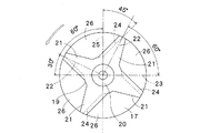
上記ポンプ室8には、環状の上記微少間隙14に近接する外径を有し回転により負圧を発生してポンプ作用を生じる吸引円板17が設けられている。該吸引円板17は、筒状の上記回転体の端部に嵌合して固定するための嵌合部18を基板の一端側に有し、他端側の中央に、回転体2と共に上記駆動軸13に取り付けるためのボルト(図示略)を固定するナット嵌めこみ用の孔20有するボス部19が形成されている。該ボス部19の外周にはボス部から半径方向に延びる羽根状の隆起部21が突設されている。該隆起部21は、吸引円板17が回転した際、固体粒子の飛距離性と方向性を考慮して、ボス部付近に負圧を発生させて処理材料を吸引し、遠心力で処理材料を外周に飛散させて効率よくポンプ作用を奏することができる適宜の形状に形成されている。図に示す実施例では、あたかも手裏剣のように、十字手裏剣型に、基端から先端に向かって次第に幅狭になる形状の4個の隆起部21を形成してあるが、3個、5〜10個等複数の隆起部を設けることができる。そして、研究によれば、各隆起部21は、図3に示すように、上記吸引円板17の円形を4等分し、隆起部21の中央線22が、円の中心線23から約60度の角度で傾斜し、回転した際、処理材料が当接する隆起部側面24が上記ボス部19の外径、すなわち円形の上記中心線23に直行する中心線25に対し約45度の角度で傾斜している形状が好ましいことが確かめられた。また、上記隆起部側面24は、回転した際、ボス部19から吸引円板の外周に流れる処理材料が上記隆起部側面24側に入り込むよう傾斜しており(図5参照)、隆起部21の外表面から見て隆起部に沿って少し内方に凹んでいる。
The pump chamber 8 is provided with a
図7は、隆起部側面24の傾斜角度による吸引円板17の駆動作用の相違を示している。図7に示すように該隆起部側面24に当たったスラリーに含まれている粗大粒子は、吸引円板の回転により吸引円板の回転方向(入力方向)と、半径方向(出力方向)に飛ばされるが、同(A)に示すように、傾斜角度を約45度に形成すると、回転方向(入力方向)に飛ばされるものと、半径方向(出力方向)に飛ばされるものがほぼ等しくなり、吸引円板を安定状態で運転することが可能となる。これに対し、例えば約30度と、傾斜角度を大きくすると、同図(B)に示すように衝突量が多くなり、円板を回転させるための動力が大きくなり、また発熱も多くなって処理材料に影響を与えるおそれがある。一方、同図(C)に示すように、傾斜度が例えば約60度と小さいと、衝突が少なくなり、円周方向流が主体となって吐き出しが弱くなり、ポンプ作用が減少する。
FIG. 7 shows the difference in the driving action of the
上記のように、隆起部21の先端をボス部側の基端の幅より次第に狭く形成したことにより隣接する隆起部との間には円周方向の幅が中心部で狭く外周部で幅広になった凹部空間26が形成される。この凹部空間26には、負圧によりポンプ室に入った処理材料が入り込み、吸収引板17の回転により凹部空間26を通って外周に向かって拡散されるが、外周縁が幅広になっているので、吐出量を増大させることができる。その結果、吸引円板によるポンプ作用が高められ、上記環状の微少間隙に処理材料を積極的に送り込むことができる。
As described above, the distal end of the raised
上記のようにしてポンプ室8から環状に微少間隙14に送り込まれた処理材料は、回転体2の外面と処理槽1の内壁間で圧縮、剪断作用をうけて混練・分散され、上記吐出口6から吐出する。吐出口6から出た処理材料は配管7を通してホッパー4に戻り、再度供給口5から処理槽1に自己吸引され、所望程度になるまで連続式に混練・分散される。
The processing material fed into the
図8に示す実施例は、回転体2の外面の形状が上記図1に示す実施例と相違している。この実施例では、回転体2は軸方向に沿って略平行四辺形の撹拌突起27を間隔をあけて多数設けてある。この平行四辺形は、回転体の軸方向に長い2辺が並び、他の斜行する2辺は供給口側から吐出口側に向かって傾斜している。この回転体2によれば、処理槽1の内壁と回転体2の外面間の環状の微少間隙14に送り込まれた処理材料はあたかも栓流(プラグフロー)状に流れ、効率よく混練・分散することができる。
The embodiment shown in FIG. 8 is different from the embodiment shown in FIG. 1 in the shape of the outer surface of the
上記実施例では、吸引円板によるポンプ作用は遠心ポンプを応用しており、渦巻ポンプに似ているが、隆起部の外側に位置するよう複数の案内羽根を前蓋の内側に設けてタービンポンプ様のポンプ作用にすることもできる。 In the above embodiment, the pump action by the suction disk applies a centrifugal pump, which is similar to a spiral pump, but is provided with a plurality of guide vanes on the inside of the front lid so as to be located outside the raised portion. It is possible to have a similar pumping action.
(実施例1)
株式会社井上製作所のセラミック回転体(ローター)を有する混練・分散機CPM−2を使用し、ローター2の端部に、図8に示すように吸引円板17を取付けた。ホッパー4に水を供給し、周速3.6m/secで運転したところ、1.7kg/minの吐出量で、滞留時間は4.4秒であり、水柱圧力計で測定したところ、ポンプ室に0.007MPa(GAUGE)の吸引圧を生じた。
また、周速11m/secで運転したところ、8.6kg/minの吐出量で、滞留時間は0.87秒、吸引圧は0.034MPa(GAUGE)であった。
(Example 1)
A kneading and dispersing machine CPM-2 having a ceramic rotating body (rotor) manufactured by Inoue Seisakusho Co., Ltd. was used, and a
When operated at a peripheral speed of 11 m / sec, the discharge rate was 8.6 kg / min, the residence time was 0.87 seconds, and the suction pressure was 0.034 MPa (GAUGE).
(実施例2)
同じ装置を用い、ホッパーに供給粘度55dPa・sの2.25%のCMC(カルボキシ メチルセルロース)水溶液を供給して運転した。吐出時27dPa・sで周速7.3m/sec時、0.13kg/minの吐出量で、滞留時間は58秒、吸引圧は0.01MPa(GAUGE)であった。
また、周速15m/secで運転したところ、4.9kg/minの吐出量で、滞留時間は1.5秒、吸引圧は0.05MPa(GAUGE)であり、中粘度材料の処理も可能であることが確かめられた。
(評価)
実施例1、2に示す通り吸収円板によりポンプ室に負圧を生じて吸引圧を発生することができ、従来のような供給ポンプを処理槽の外部に設ける必要がないことが確かめられた。
(Example 2)
Using the same apparatus, a 2.25% CMC (carboxymethylcellulose) aqueous solution having a supply viscosity of 55 dPa · s was supplied to the hopper and operated. At a discharge rate of 27 dPa · s and a peripheral speed of 7.3 m / sec, a discharge rate of 0.13 kg / min, a residence time of 58 seconds, and a suction pressure of 0.01 MPa (GAUGE).
In addition, when operated at a peripheral speed of 15 m / sec, with a discharge rate of 4.9 kg / min, a residence time of 1.5 seconds and a suction pressure of 0.05 MPa (GAUGE), medium viscosity materials can be processed. It was confirmed that there was.
(Evaluation)
As shown in Examples 1 and 2, it was confirmed that a suction pressure can be generated by generating a negative pressure in the pump chamber by the absorption disk, and it is confirmed that it is not necessary to provide a conventional supply pump outside the processing tank. .
上記と同じ装置を用い、吸引円板の代わりに表面が平らな従来の円板ワッシャーを取り付けた。ホッパーに水を供給し、周速3.6m/secから11m/secまで運転し、水柱圧力計による吸引圧を確認したところ、吸引圧は極めて低く、吐出量は約2kg/minであり、ポンプ作用は認められなかった。 Using the same apparatus as above, a conventional disk washer with a flat surface was attached instead of the suction disk. Water was supplied to the hopper, the peripheral speed was operated from 3.6m / sec to 11m / sec, and the suction pressure by the water column pressure gauge was confirmed. As a result, the suction pressure was extremely low and the discharge amount was about 2kg / min. No effect was observed.
以上のように、処理槽1の供給口5側にポンプ室8を設けてその内部で吸引円板17を回転させることにより負圧によるポンプ作用を生じさせることができ、従来のように供給ポンプを処理槽の外部に設置する必要がない。そのため、供給ポンプが不要になり、かつ連続化のための配管を短縮することが可能となり、少量の処理材料の確認テストにも使用でき、スラリーを自己吸引式に連続して効率よく混練・分散処理することができる。
As described above, by providing the pump chamber 8 on the supply port 5 side of the
1 処理槽
2 回転体
5 供給口
6 吐出口
8 ポンプ室
14 微少間隙
17 吸引円板
21 隆起部
24 隆起部側面
26 凹部空間
DESCRIPTION OF
Claims (5)
Priority Applications (1)
| Application Number | Priority Date | Filing Date | Title |
|---|---|---|---|
| JP2016047112A JP6726003B2 (en) | 2016-03-10 | 2016-03-10 | Slurry kneading/dispersing device |
Applications Claiming Priority (1)
| Application Number | Priority Date | Filing Date | Title |
|---|---|---|---|
| JP2016047112A JP6726003B2 (en) | 2016-03-10 | 2016-03-10 | Slurry kneading/dispersing device |
Publications (2)
| Publication Number | Publication Date |
|---|---|
| JP2017159259A true JP2017159259A (en) | 2017-09-14 |
| JP6726003B2 JP6726003B2 (en) | 2020-07-22 |
Family
ID=59854598
Family Applications (1)
| Application Number | Title | Priority Date | Filing Date |
|---|---|---|---|
| JP2016047112A Active JP6726003B2 (en) | 2016-03-10 | 2016-03-10 | Slurry kneading/dispersing device |
Country Status (1)
| Country | Link |
|---|---|
| JP (1) | JP6726003B2 (en) |
Cited By (1)
| Publication number | Priority date | Publication date | Assignee | Title |
|---|---|---|---|---|
| KR20220024980A (en) * | 2019-07-31 | 2022-03-03 | 션전 상수이 스마트 이큅먼트 씨오., 엘티디. | Impeller assembly and solid-liquid mixing device using the same |
Citations (9)
| Publication number | Priority date | Publication date | Assignee | Title |
|---|---|---|---|---|
| JPS5756322A (en) * | 1980-09-24 | 1982-04-03 | Toshiba Corp | Manufacture of nonlinear resistor |
| JPS57106441U (en) * | 1980-12-24 | 1982-06-30 | ||
| JPH0515758A (en) * | 1991-07-12 | 1993-01-26 | Ebara Corp | High viscosity power/liquid mixing/dispersion device |
| JPH0515756A (en) * | 1991-07-12 | 1993-01-26 | Ebara Corp | Powder/liquid mixing/dispersion device with preliminarily stirring blade |
| JPH07256072A (en) * | 1994-03-18 | 1995-10-09 | Inoue Seisakusho:Kk | Medium dispersing machine |
| JPH10202078A (en) * | 1997-01-20 | 1998-08-04 | Masumi Kusunoki | Compact dispersing machine |
| JPH1157438A (en) * | 1997-08-25 | 1999-03-02 | Nippon Paint Co Ltd | Dispersion method and dispersion machine |
| JP2011224446A (en) * | 2010-04-16 | 2011-11-10 | Powrex Corp | Agitation treatment device |
| JP3177741U (en) * | 2012-06-04 | 2012-08-16 | 株式会社井上製作所 | Wet medium disperser |
-
2016
- 2016-03-10 JP JP2016047112A patent/JP6726003B2/en active Active
Patent Citations (9)
| Publication number | Priority date | Publication date | Assignee | Title |
|---|---|---|---|---|
| JPS5756322A (en) * | 1980-09-24 | 1982-04-03 | Toshiba Corp | Manufacture of nonlinear resistor |
| JPS57106441U (en) * | 1980-12-24 | 1982-06-30 | ||
| JPH0515758A (en) * | 1991-07-12 | 1993-01-26 | Ebara Corp | High viscosity power/liquid mixing/dispersion device |
| JPH0515756A (en) * | 1991-07-12 | 1993-01-26 | Ebara Corp | Powder/liquid mixing/dispersion device with preliminarily stirring blade |
| JPH07256072A (en) * | 1994-03-18 | 1995-10-09 | Inoue Seisakusho:Kk | Medium dispersing machine |
| JPH10202078A (en) * | 1997-01-20 | 1998-08-04 | Masumi Kusunoki | Compact dispersing machine |
| JPH1157438A (en) * | 1997-08-25 | 1999-03-02 | Nippon Paint Co Ltd | Dispersion method and dispersion machine |
| JP2011224446A (en) * | 2010-04-16 | 2011-11-10 | Powrex Corp | Agitation treatment device |
| JP3177741U (en) * | 2012-06-04 | 2012-08-16 | 株式会社井上製作所 | Wet medium disperser |
Cited By (4)
| Publication number | Priority date | Publication date | Assignee | Title |
|---|---|---|---|---|
| KR20220024980A (en) * | 2019-07-31 | 2022-03-03 | 션전 상수이 스마트 이큅먼트 씨오., 엘티디. | Impeller assembly and solid-liquid mixing device using the same |
| JP2022547780A (en) * | 2019-07-31 | 2022-11-16 | 深▲セン▼市尚水智能設備有限公司 | Impeller assembly and solid-liquid mixing device using the impeller assembly |
| JP7270832B2 (en) | 2019-07-31 | 2023-05-10 | 深▲セン▼市尚水智能股▲フン▼有限公司 | Impeller assembly and solid-liquid mixing device using the impeller assembly |
| KR102643934B1 (en) * | 2019-07-31 | 2024-03-05 | 상수이 스마테크 리미티드 | Impeller assembly and mixing device of solid and liquid using the same |
Also Published As
| Publication number | Publication date |
|---|---|
| JP6726003B2 (en) | 2020-07-22 |
Similar Documents
| Publication | Publication Date | Title |
|---|---|---|
| KR101658410B1 (en) | Dispersing and emulsifying apparatus for high viscosity fluid | |
| JP2011005349A (en) | Stirring rotor, and stirrer | |
| JP6011155B2 (en) | Circulation type media stirring mill | |
| TWI604891B (en) | Media mixing mill | |
| US4350305A (en) | Micro-mill-mixer | |
| JP2019147077A (en) | Agitator | |
| JP6687422B2 (en) | Distributed system | |
| JP2013039508A (en) | Medium stirring type crusher | |
| TW201829054A (en) | Dispersion device and defoaming device | |
| JP2017159259A (en) | Slurry mixing and dispersing apparatus | |
| US1496641A (en) | Mixing, incorporating, and disintegrating machine | |
| JP7111399B1 (en) | Disperser | |
| TWI460008B (en) | Centrifugal dispersing device | |
| JP5794564B2 (en) | Stirrer | |
| JP5302265B2 (en) | Rotating body for stirring and stirring device | |
| KR101678112B1 (en) | Powder mixer | |
| KR101707814B1 (en) | Dispersing and emulsifying apparatus for low viscosity fluid | |
| JP7429039B2 (en) | wet bead mill | |
| JP2022089805A (en) | Continuous powder treatment device | |
| JP4901353B2 (en) | Media stirring mill | |
| JP2898523B2 (en) | Dispersing apparatus and dispersing method | |
| JP2016028799A (en) | Kneading and stirring device | |
| JP7111400B1 (en) | Disperser | |
| JP4189831B2 (en) | Media distribution device | |
| JP4140423B2 (en) | Wet medium disperser and stirring disk used therefor |
Legal Events
| Date | Code | Title | Description |
|---|---|---|---|
| A621 | Written request for application examination |
Free format text: JAPANESE INTERMEDIATE CODE: A621 Effective date: 20190110 |
|
| A977 | Report on retrieval |
Free format text: JAPANESE INTERMEDIATE CODE: A971007 Effective date: 20190913 |
|
| A131 | Notification of reasons for refusal |
Free format text: JAPANESE INTERMEDIATE CODE: A131 Effective date: 20190924 |
|
| A521 | Request for written amendment filed |
Free format text: JAPANESE INTERMEDIATE CODE: A523 Effective date: 20190930 |
|
| A131 | Notification of reasons for refusal |
Free format text: JAPANESE INTERMEDIATE CODE: A131 Effective date: 20191126 |
|
| A521 | Request for written amendment filed |
Free format text: JAPANESE INTERMEDIATE CODE: A523 Effective date: 20191209 |
|
| A521 | Request for written amendment filed |
Free format text: JAPANESE INTERMEDIATE CODE: A523 Effective date: 20200117 |
|
| TRDD | Decision of grant or rejection written | ||
| A01 | Written decision to grant a patent or to grant a registration (utility model) |
Free format text: JAPANESE INTERMEDIATE CODE: A01 Effective date: 20200602 |
|
| A61 | First payment of annual fees (during grant procedure) |
Free format text: JAPANESE INTERMEDIATE CODE: A61 Effective date: 20200626 |
|
| R150 | Certificate of patent or registration of utility model |
Ref document number: 6726003 Country of ref document: JP Free format text: JAPANESE INTERMEDIATE CODE: R150 |
|
| R250 | Receipt of annual fees |
Free format text: JAPANESE INTERMEDIATE CODE: R250 |