JP2017155772A - Gear device - Google Patents
Gear device Download PDFInfo
- Publication number
- JP2017155772A JP2017155772A JP2016037520A JP2016037520A JP2017155772A JP 2017155772 A JP2017155772 A JP 2017155772A JP 2016037520 A JP2016037520 A JP 2016037520A JP 2016037520 A JP2016037520 A JP 2016037520A JP 2017155772 A JP2017155772 A JP 2017155772A
- Authority
- JP
- Japan
- Prior art keywords
- hole
- crankshaft
- output shaft
- carrier
- peripheral surface
- Prior art date
- Legal status (The legal status is an assumption and is not a legal conclusion. Google has not performed a legal analysis and makes no representation as to the accuracy of the status listed.)
- Granted
Links
- 230000002093 peripheral effect Effects 0.000 claims abstract description 61
- 239000011148 porous material Substances 0.000 claims 1
- 230000005540 biological transmission Effects 0.000 abstract description 20
- 238000003780 insertion Methods 0.000 description 10
- 230000037431 insertion Effects 0.000 description 10
- 239000000758 substrate Substances 0.000 description 10
- 238000004519 manufacturing process Methods 0.000 description 3
- 230000000694 effects Effects 0.000 description 1
- 230000013011 mating Effects 0.000 description 1
- 238000000034 method Methods 0.000 description 1
- 238000012986 modification Methods 0.000 description 1
- 230000004048 modification Effects 0.000 description 1
Images


Classifications
-
- F—MECHANICAL ENGINEERING; LIGHTING; HEATING; WEAPONS; BLASTING
- F16—ENGINEERING ELEMENTS AND UNITS; GENERAL MEASURES FOR PRODUCING AND MAINTAINING EFFECTIVE FUNCTIONING OF MACHINES OR INSTALLATIONS; THERMAL INSULATION IN GENERAL
- F16H—GEARING
- F16H49/00—Other gearings
- F16H49/001—Wave gearings, e.g. harmonic drive transmissions
-
- F—MECHANICAL ENGINEERING; LIGHTING; HEATING; WEAPONS; BLASTING
- F16—ENGINEERING ELEMENTS AND UNITS; GENERAL MEASURES FOR PRODUCING AND MAINTAINING EFFECTIVE FUNCTIONING OF MACHINES OR INSTALLATIONS; THERMAL INSULATION IN GENERAL
- F16H—GEARING
- F16H1/00—Toothed gearings for conveying rotary motion
- F16H1/28—Toothed gearings for conveying rotary motion with gears having orbital motion
- F16H1/32—Toothed gearings for conveying rotary motion with gears having orbital motion in which the central axis of the gearing lies inside the periphery of an orbital gear
-
- F—MECHANICAL ENGINEERING; LIGHTING; HEATING; WEAPONS; BLASTING
- F16—ENGINEERING ELEMENTS AND UNITS; GENERAL MEASURES FOR PRODUCING AND MAINTAINING EFFECTIVE FUNCTIONING OF MACHINES OR INSTALLATIONS; THERMAL INSULATION IN GENERAL
- F16H—GEARING
- F16H57/00—General details of gearing
- F16H57/02—Gearboxes; Mounting gearing therein
- F16H57/021—Shaft support structures, e.g. partition walls, bearing eyes, casing walls or covers with bearings
Landscapes
- Engineering & Computer Science (AREA)
- General Engineering & Computer Science (AREA)
- Mechanical Engineering (AREA)
- Retarders (AREA)
Abstract
Description
本発明は、歯車装置に関する。 The present invention relates to a gear device.
近年、産業用ロボットや工作機械といった様々な技術分野において、様々な歯車装置が開発されている。このような歯車装置の一例として、特許文献1には、内歯を有する外筒と、軸回りに回転可能なクランク軸と、当該クランク軸の回転に応じて外筒の内歯に噛み合いながら揺動回転する外歯歯車と、クランク軸を回転可能に支持するとともに外歯歯車の揺動回転に応じて外筒に対して相対的に回転するキャリアと、を備えた歯車装置が記載されている。この歯車装置のキャリアには、クランク軸が配置されるクランク軸孔と、クランク軸にトルクを入力する入力ギアを挿入する貫通孔と、が設けられており、クランク軸孔と貫通孔とがキャリアを回転軸方向に貫いている。 In recent years, various gear devices have been developed in various technical fields such as industrial robots and machine tools. As an example of such a gear device, Patent Document 1 discloses an outer cylinder having internal teeth, a crankshaft that can rotate around an axis, and a gear that meshes with the internal teeth of the outer cylinder in accordance with the rotation of the crankshaft. A gear device is described that includes an external gear that rotates and rotates, and a carrier that rotatably supports the crankshaft and that rotates relative to the outer cylinder in response to the swinging rotation of the external gear. . The carrier of this gear device is provided with a crankshaft hole in which the crankshaft is disposed, and a through hole into which an input gear for inputting torque to the crankshaft is inserted. The crankshaft hole and the through hole are provided in the carrier. Through the axis of rotation.
特許文献1の歯車装置では、回転軸方向の一方側から貫通孔に挿入された入力ギアがクランク軸にトルクを入力することにより、当該クランク軸が回転する。そして、クランク軸の回転に応じて外歯歯車が揺動回転し、これによってキャリアが回転軸回りに回転する。 In the gear device of Patent Document 1, an input gear inserted into the through hole from one side in the direction of the rotation shaft inputs torque to the crankshaft, whereby the crankshaft rotates. Then, according to the rotation of the crankshaft, the external gear rotates and rotates, whereby the carrier rotates about the rotation axis.
特許文献1の歯車装置において、キャリアの回転を相手側部材に伝達するには、当該キャリアの軸方向端面に形成されたネジ孔を利用して、相手側部材をキャリアの軸方向端面に直接取り付ける。 In the gear device of Patent Document 1, in order to transmit the rotation of the carrier to the counterpart member, the counterpart member is directly attached to the axial end surface of the carrier using a screw hole formed in the axial end surface of the carrier. .
一方で、キャリアの軸方向端面に相手側部材を直接取り付けるのではなく、回転軸回りに回転可能な出力軸部を介して、キャリアの回転を相手側部材に伝達することがある。この場合、出力軸部は、キャリアの回転軸中心に沿って入力部ギアの反対側に延びるように当該キャリアに一体に形成されてもよいし、キャリアとは別個に形成されて入力ギアの反対側から当該キャリアの貫通孔に圧入されてもよい。 On the other hand, instead of directly attaching the counterpart member to the end surface in the axial direction of the carrier, the rotation of the carrier may be transmitted to the counterpart member via the output shaft portion that can rotate around the rotation axis. In this case, the output shaft portion may be formed integrally with the carrier so as to extend to the opposite side of the input portion gear along the center of the rotation axis of the carrier, or formed separately from the carrier and opposite to the input gear. It may be press-fitted into the through-hole of the carrier from the side.
しかしながら、出力軸部をキャリアと一体に形成する場合、キャリアの製造過程において当該出力軸部の形成工程が必要となり、製造コストが増大する。一方で、出力軸部をキャリアの貫通孔に圧入する場合、当該出力軸部とキャリアとが周方向において接していないため、キャリアから出力軸部への伝達トルクが低くなってしまう。 However, when the output shaft portion is formed integrally with the carrier, a process for forming the output shaft portion is required in the carrier manufacturing process, and the manufacturing cost increases. On the other hand, when the output shaft portion is press-fitted into the through hole of the carrier, the output shaft portion and the carrier are not in contact with each other in the circumferential direction, so that the transmission torque from the carrier to the output shaft portion is reduced.
そこで、キャリアから出力軸部への伝達トルクを十分に確保するためには、例えば出力軸部の外周面と貫通孔を取り囲むキャリアの内周面とを周方向の全体に亘って凹凸状に形成することが考えられる。これにより、出力軸部の外周面とキャリアの内周面とが噛み合い、周方向において出力軸部の外周面とキャリアの内周面とが接するため、キャリアから出力軸部への伝達トルクを十分に確保することができる。しかしながらこの場合、貫通孔への出力部の圧入によって、キャリアのうち貫通孔とクランク軸孔との間に位置する比較的薄肉な部位に対して径方向の外側に強い力が加わる。この場合、クランク軸孔の内周面に支持されるクランク軸にも強い力が加わることになり、当該クランク軸の回転に支障をきたす可能性がある。 Therefore, in order to ensure sufficient transmission torque from the carrier to the output shaft portion, for example, the outer peripheral surface of the output shaft portion and the inner peripheral surface of the carrier surrounding the through hole are formed in an uneven shape over the entire circumferential direction. It is possible to do. As a result, the outer peripheral surface of the output shaft portion meshes with the inner peripheral surface of the carrier, and the outer peripheral surface of the output shaft portion and the inner peripheral surface of the carrier are in contact with each other in the circumferential direction. Can be secured. However, in this case, a strong force is applied to the outer side in the radial direction on the relatively thin portion of the carrier located between the through hole and the crankshaft hole by press-fitting the output portion into the through hole. In this case, a strong force is also applied to the crankshaft supported by the inner peripheral surface of the crankshaft hole, which may hinder the rotation of the crankshaft.
本発明は、上記の観点からなされたものであり、その目的は、コストの増大を抑止しつつ伝達トルクを十分に確保できるとともに、クランク軸の回転に支障をきたす可能性を低減できる歯車装置を提供することにある。 The present invention has been made from the above viewpoint, and an object of the present invention is to provide a gear device that can sufficiently secure transmission torque while suppressing an increase in cost and can reduce the possibility of hindrance to rotation of the crankshaft. It is to provide.
本発明に係る歯車装置は、外周面に凹凸が形成された出力軸部が圧入されるとともに回転軸に沿って設けられた中央孔、および前記回転軸を中心とした径方向において前記中央孔と並ぶように設けられたクランク軸孔を有するキャリアと、前記クランク軸孔の内周面に支持されており、前記回転軸を中心として外筒に対して前記キャリアを相対的に回転させるクランク軸と、を備える歯車装置であって、前記中央孔の内周面は、前記出力軸部の前記凹凸に噛み合う凹凸部を有しており、前記凹凸部は、前記径方向における最も外側に位置する複数の最外部と、当該径方向における最も内側に位置する複数の最内部と、前記最外部と前記最内部とを繋ぐとともに前記前記径方向に対して傾斜した複数の側面と、を含んでおり、前記中央孔の内周面は、前記径方向において、前記中央孔と前記クランク軸孔とが対向する領域に含まれる第1部位と、前記周方向において前記第1部位に隣接する第2部位と、を有しており、前記各側面は、前記第2部位に形成されている。 The gear device according to the present invention includes a center hole provided along the rotation shaft while being press-fitted with an output shaft portion having irregularities formed on the outer peripheral surface, and the center hole in the radial direction around the rotation shaft. A carrier having a crankshaft hole provided so as to be lined up; and a crankshaft that is supported on an inner peripheral surface of the crankshaft hole and that rotates the carrier relative to an outer cylinder about the rotating shaft; The inner peripheral surface of the central hole has a concavo-convex portion that meshes with the concavo-convex portion of the output shaft portion, and the concavo-convex portion is a plurality of outermost portions in the radial direction. The outermost part, a plurality of innermost parts located on the innermost side in the radial direction, and a plurality of side surfaces that connect the outermost part and the innermost part and are inclined with respect to the radial direction, Inner circumference of the central hole Has a first part included in a region where the central hole and the crankshaft hole are opposed to each other in the radial direction, and a second part adjacent to the first part in the circumferential direction, Each said side is formed in the said 2nd site | part.
上記の歯車装置では、キャリアの中央孔に出力軸部を圧入することにより当該出力軸部をキャリアに固定しているため、キャリアと出力軸部とを一体に形成する場合に比してコストの増大を抑止することができる。 In the above gear device, since the output shaft portion is fixed to the carrier by press-fitting the output shaft portion into the center hole of the carrier, the cost is lower than when the carrier and the output shaft portion are integrally formed. The increase can be suppressed.
また、上記の歯車装置では、中央孔の内周面が出力軸部の凹凸に噛み合う凹凸部を有しており、当該凹凸部に含まれる複数の側面が周方向において出力軸部の外周面に接するため、キャリアから出力軸部への伝達トルクを十分に確保することができる。 Further, in the above gear device, the inner peripheral surface of the central hole has an uneven portion that meshes with the uneven portion of the output shaft portion, and a plurality of side surfaces included in the uneven portion are on the outer peripheral surface of the output shaft portion in the circumferential direction. Therefore, the transmission torque from the carrier to the output shaft portion can be sufficiently ensured.
ところで、中央孔に出力軸部が圧入されると、当該凹凸部に含まれる複数の側面には、出力軸部の外周面が押し当たることになる。ここで、複数の側面は、回転軸を中心とした径方向に対して傾斜している。このため、中央孔に出力軸部を圧入した際に、当該出力軸部から中央孔の内周面へと径方向の外側に加わる力は、複数の側面が形成された領域ほど大きくなる。 By the way, when the output shaft portion is press-fitted into the central hole, the outer peripheral surface of the output shaft portion is pressed against a plurality of side surfaces included in the uneven portion. Here, the plurality of side surfaces are inclined with respect to the radial direction around the rotation axis. For this reason, when the output shaft portion is press-fitted into the central hole, the force applied to the outer side in the radial direction from the output shaft portion to the inner peripheral surface of the central hole becomes larger in the region where the plurality of side surfaces are formed.
そこで、上記の歯車装置では、キャリアのうち中央孔とクランク軸孔との間に位置する比較的薄肉の部位に対して強い力が加わることを抑止するため、中央孔の内周面のうち、径方向において中央孔とクランク軸孔とが対向する領域に含まれる第1部位には複数の側面を形成せず、周方向において当該第1部位に隣接する第2部位にのみ複数の側面を形成している。これにより、クランク軸孔の内周面に支持されるクランク軸に強い力が加わることを抑止でき、当該クランク軸の回転に支障をきたす可能性を低減できる。 Therefore, in the above gear device, in order to prevent a strong force from being applied to a relatively thin portion located between the center hole and the crankshaft hole in the carrier, of the inner peripheral surface of the center hole, A plurality of side surfaces are not formed in the first portion included in the region where the central hole and the crankshaft hole face each other in the radial direction, and a plurality of side surfaces are formed only in the second portion adjacent to the first portion in the circumferential direction. doing. Thereby, it can suppress that strong force is added to the crankshaft supported by the internal peripheral surface of a crankshaft hole, and can reduce possibility that the rotation of the said crankshaft will be obstructed.
このように、上記の歯車装置では、キャリアの製造コストの増大を抑止しつつ、キャリアから出力軸部への伝達トルクを十分に確保できるとともに、クランク軸の回転に支障をきたす可能性を低減できる。 As described above, in the above gear device, it is possible to sufficiently secure a transmission torque from the carrier to the output shaft portion while suppressing an increase in the manufacturing cost of the carrier, and to reduce the possibility of hindering the rotation of the crankshaft. .
上記の歯車装置では、前記第1部位は、前記周方向に沿って延びる曲面であり、前記各側面のうち前記第1部位に最も近い側面における前記径方向の外端に繋がっていることが好ましい。 In said gear apparatus, it is preferable that the said 1st site | part is a curved surface extended along the said circumferential direction, and is connected with the said radial outer end in the side surface nearest to the said 1st site | part among each said side surface. .
この場合、前記回転軸から前記第1部位までの長さは、前記回転軸から前記最外部までの長さ以上であることが好ましい。 In this case, it is preferable that the length from the rotating shaft to the first portion is equal to or longer than the length from the rotating shaft to the outermost portion.
上記の構成によれば、出力軸部の外周面に形成される凹凸が周方向の全域に亘って一様な形状をなしている場合であっても、当該出力軸部を中央孔に圧入することが可能である。このため、中央孔の内周面に形成された凹凸部に合わせて出力軸部の外周面の一部にのみ凹凸を形成する必要がなく、従来の出力軸部をそのまま用いることが可能である。 According to said structure, even if the unevenness | corrugation formed in the outer peripheral surface of an output shaft part has comprised the uniform shape over the whole region of the circumferential direction, the said output shaft part is press-fit in a center hole. It is possible. For this reason, it is not necessary to form unevenness only on a part of the outer peripheral surface of the output shaft portion in accordance with the uneven portion formed on the inner peripheral surface of the central hole, and the conventional output shaft portion can be used as it is. .
上記の歯車装置では、前記第1部位は、前記周方向に沿って延びる曲面であり、前記各側面のうち前記第1部位に最も近い側面における前記径方向の内端に繋がっていることが好ましい。 In the above gear device, it is preferable that the first part is a curved surface extending along the circumferential direction, and is connected to the radially inner end of the side surface closest to the first part among the side surfaces. .
上記の構成によれば、第1部位は、周方向に沿って延びるとともに側面のうち径方向の内端に繋がっており、当該側面のうち径方向の外端に繋がる場合に比べると径方向においてクランク軸孔から離間することになる。すなわち、上記の歯車装置では、第1部位が側面の外端に繋がる場合に比べて、キャリアのうち中央孔とクランク軸孔との間の部位の厚みを大きくすることができる。このため、中央孔への出力軸部の圧入によってクランク軸の回転に支障をきたす可能性をより低減できる。 According to the above configuration, the first portion extends along the circumferential direction and is connected to the radially inner end of the side surface, and in the radial direction compared to the case where the first portion is connected to the radially outer end of the side surface. It is separated from the crankshaft hole. That is, in the above gear device, the thickness of the portion of the carrier between the center hole and the crankshaft hole can be increased as compared with the case where the first portion is connected to the outer end of the side surface. For this reason, it is possible to further reduce the possibility of hindrance to the rotation of the crankshaft by press-fitting the output shaft portion into the central hole.
本発明に係る歯車装置では、コストの増大を抑止しつつ伝達トルクを十分に確保できるとともに、クランク軸の回転に支障をきたす可能性を低減することができる。 In the gear device according to the present invention, it is possible to sufficiently ensure the transmission torque while suppressing an increase in cost, and it is possible to reduce the possibility of hindering the rotation of the crankshaft.
以下、本発明の各実施形態について、図面を参照しながら説明する。但し、以下で参照する各図は、説明の便宜上、本実施形態に係る歯車装置X1の構成要素のうち主要な構成要素のみを簡略化して示したものである。したがって、本実施形態に係る歯車装置X1は、本明細書が参照する各図に示されていない任意の構成要素を備え得る。 Hereinafter, embodiments of the present invention will be described with reference to the drawings. However, each drawing referred to below shows only the main components in a simplified manner among the components of the gear device X1 according to the present embodiment for convenience of explanation. Therefore, the gear device X1 according to the present embodiment can include arbitrary components not shown in the drawings referred to in this specification.
<第1実施形態>
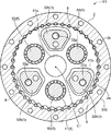
図1および図2に示すように、歯車装置X1は、偏心揺動型の歯車装置であって、外筒2と、キャリア3と、揺動歯車4と、クランク軸5と、伝達歯車7と、を備えている。歯車装置X1では、入力トルクが伝達歯車7を介してクランク軸5に伝達されることにより、当該クランク軸5が回転し、これに伴って揺動歯車4が揺動回転することにより、外筒2とキャリア3とが相対的に回転する。
<First Embodiment>
As shown in FIGS. 1 and 2, the gear device X <b> 1 is an eccentric oscillating gear device, and includes an
外筒2は、回転軸C1を中心軸とする略円筒形状をなしている。外筒2の内周面2aには、多数のピン溝が形成されている。各ピン溝は、回転軸C1方向に延びるように配置され、当該回転軸C1方向に直交する断面において半円形の断面形状を有している。各ピン溝は、外筒2の周方向に等間隔で並んでいる。
The
歯車装置X1は、外筒2の内周面2aに取り付けられる複数の内歯ピン8をさらに備えている。各内歯ピン8は、回転軸C1方向に延びる円柱形状をなしている。また、各内歯ピン8は、外筒2の内周面2aに形成された各ピン溝に取り付けられている。
The gear device X <b> 1 further includes a plurality of internal teeth pins 8 attached to the inner
外筒2には、当該外筒2を回転軸C1方向に貫く取付け孔2bが複数形成されている。各取付け孔2bは外筒2の周方向に等間隔で並んでいる。各取付け孔2bは、例えば、外筒2に対して図略の相手側部材を取り付ける際に利用される。外筒2に対して取り付けられる相手側部材が回転しないベース部材である場合、外筒2は、歯車装置X1における固定側の部材となる。
The
キャリア3は、回転軸C1を中心として外筒2に対して相対的に回転可能なように構成される。キャリア3は、回転軸C1方向において揺動歯車4を挟むように構成されており、外筒2と同心状に配置されている。キャリア3は、回転軸C1方向において互いに対向する第1部材31および第2部材32を有している。第1部材31と第2部材32とは、締結部材Bを介して互いに締結されている。
The
第1部材31は、略円板状をなしている。第1部材31は、一部が外筒2の内部に位置しており、残部が回転軸C1方向において外筒2の外部に位置している。第1部材31は、回転軸C1方向において第2部材32に対向する対向面と、当該面の反対側に位置する第1軸方向端面31Aと、を含んでいる。
The
第1部材31には、中央孔31aと、クランク軸孔31bと、挿入孔31dと、が形成されている。
The
中央孔31aは、第1部材31を回転軸C1に沿って第1軸方向端面31Aから対向面に亘って貫くように、第1部材31の中央部分に形成されている。中央孔31aの中心は、回転軸C1である。
The
クランク軸孔31bは、クランク軸5の一部が収容される孔である。クランク軸孔31bは、キャリア3の径方向において中央孔31aと並んでいる。本実施形態では、3つのクランク軸孔31bが、中央孔31aの外側においてキャリア3の周方向に並んでいる。各クランク軸孔31bは、第1部位31を第1軸方向端面31Aから対向面に亘って回転軸C1方向に貫く貫通孔である。なお、クランク軸孔31bの数は任意であって、後述するクランク軸5の数に応じて適宜変更される。
The
挿入孔31dは、締結部材Bが挿入される孔である。挿入孔31dは、キャリア3の径方向において中央孔31aの外側に複数形成されている。挿入孔31dは、キャリア3を第1軸方向端面31Aから対向面に亘って回転軸C1方向に貫くように形成されており、締結部材Bと頭部が収容される。
The
第2部材32は、略円板状の基板部32aと、当該基板部32aから第1部材31側に延びるシャフト部32bと、を有している。
The
基板部32aは、一部が外筒2の内部に位置しており、残部が回転軸C1方向において外筒2の外部に位置している。基板部32aは、回転軸C1方向においてシャフト部32bに繋がるシャフト面と、当該シャフト面の反対側に位置する第2軸方向端面32Aと、を含んでいる。
A part of the
シャフト部32bは、基板部32aのシャフト面から第1部材31に向かって回転軸C1方向に延びている。シャフト部32bは、キャリア3の周方向に並んで複数設けられている。本実施形態では、第2部材32は、3つのシャフト部32bを有している。
The
第2部材32には、中央孔32cと、クランク軸孔32eと、雌ネジ孔32gと、が形成されている。
The
中央孔32cは、第2部材32の基板部32aを回転軸C1に沿って第2軸方向端面32Aからシャフト面に亘って貫くように、基板部32aの中央部分に形成されている。中央孔32cの中心は、回転軸C1である。
The
クランク軸孔32eは、クランク軸5の一部が収容される孔である。クランク軸孔32eは、キャリア3の径方向において中央孔32cと並んでいる。本実施形態では、3つのクランク軸孔32eが、中央孔32cの外側においてキャリア3の周方向に並んでいる。各クランク軸孔32eは、第2部材32の基板部32aを第2軸方向端面32Aからシャフト面に亘って回転軸C1方向に貫く貫通孔である。なお、クランク軸孔32eの数は任意であって、後述するクランク軸5の数に応じて適宜変更される。
The
雌ネジ孔32gは、締結部材Bの雄ネジ部分が螺合する孔である。雌ネジ孔32gは、シャフト部32bのうち第1部材31の対向面に接する端面の一部が凹むように形成されている。雌ネジ孔32gは、回転軸C1方向において第1部材31の挿入孔31dに連続している。締結部材Bは、挿入孔31dを通じてキャリア3に挿入され、当該締結部材Bの雄ネジ部分がシャフト部32bの雌ネジ孔32gに螺合することによって、第1部材31と第2部材32とを締結する。
The
クランク軸5は、クランク軸孔31b,32dに収容されている。クランク軸5は、当該クランク軸5の一部がクランク軸孔31bの内周面31cとクランク軸孔32eの内周面32fとによって回転自在に支持されている。具体的に、歯車装置X1は、キャリア3に対するクランク軸5の回転を許容するクランク軸受6A,6Bをさらに備えており、当該クランク軸受6A,6Bを介してクランク軸5が内周面31c,32fに支持されている。本実施形態では、クランク軸5は、キャリア3の周方向に並んで3つ設けられている。なお、クランク軸5の数は任意であって、歯車装置X1の使用態様に応じて適宜変更することができる。
The
クランク軸5は、回転軸C1方向に延びる軸本体51と、当該軸本体51に対して偏心する偏心部52,53と、を有している。
The
軸本体51は、クランク軸孔31b,32eよりも小さい径を有している。軸本体51は、回転軸C1方向において、クランク軸孔32eから第1軸方向端面31Aの外側に亘って延びている。軸本体51は、クランク軸孔31bにおいてクランク軸受6Aを介して内周面31cに回転自在に支持されているとともに、クランク軸孔32eにおいてクランク軸受け6Bを介して内周面32fに回転自在に支持されている。
The
偏心部52,53は、軸本体51の回転中心軸に対して偏心するように当該軸本体51の中間部分に取り付けられている。偏心部52,53には、ころ軸受を介して後述する揺動歯車4が取り付けられている。これにより、偏心部52,53と揺動歯車4とは相対的に回転可能である。
The
揺動歯車4は、外筒2内に位置しており、回転軸C1方向において第1部材31と第2部材32の基板部32aとに挟まれている。揺動歯車4は、第1偏心部52に取り付けられた第1揺動歯車41と、第2偏心部53に取り付けられた第2揺動歯車42と、を有している。
The
揺動歯車41,42は、外筒2の内径よりも少し小さい外径を有しており、その外周面に複数の外歯が形成されている。揺動歯車41,42のそれぞれの外周面に形成された外歯の歯数は、内歯ピン8の数よりも僅かに少ない。これにより、第1揺動歯車41と第2揺動歯車42とは、外筒2の内部において各外歯が各内歯ピン8に噛み合うように、互いに異なる位相で揺動回転することができる。
The oscillating gears 41 and 42 have an outer diameter slightly smaller than the inner diameter of the
第1揺動歯車41には、中央孔31a,32cの位置に対応する中央孔41aと、シャフト部32bが挿入された挿入孔41bと、第1偏心部52が挿入されたクランク軸孔41cと、が形成されている。中央孔41a、挿入孔41b、およびクランク軸孔41cは、第1揺動歯車41を回転軸C1方向に貫いている。
The
第2揺動歯車42には、中央孔31a,32cの位置に対応する中央孔42aと、シャフト部32bが挿入された挿入孔42bと、第2偏心部53が挿入されたクランク軸孔42cと、が形成されている。中央孔42a、挿入孔42b、およびクランク軸孔42cは、第1揺動歯車41を回転軸C1方向に貫いている。
The
なお、本実施形態では、揺動歯車4は、第1揺動歯車41と第2揺動歯車42との2つの揺動歯車を有しているが、これに限らず、1つの揺動歯車のみを有していてもよいし、3つ以上の揺動歯車を有していてもよい。
In the present embodiment, the
伝達歯車7は、クランク軸5に入力トルクを伝達して当該クランク軸5を回転させる。本実施形態では、伝達歯車7は、3つのクランク軸5の位置に対応して3つ設けられている。伝達歯車7は、回転軸C1方向において第1部材31を挟んで第2部材32とは反対側に位置している。伝達歯車7は、回転軸C1方向において第1軸方向端面31Aの外側に突出したクランク軸5の軸本体51に取り付けられている。伝達歯車7は、当該伝達歯車7を回転軸C1方向における両側から挟み込むように軸本体51の小径部51aに取り付けられた止め輪によって、当該回転軸C1方向の動きを規制される。
The
なお、本実施形態で伝達歯車7は、回転軸C1方向において第1部材31を挟んで第2部材32とは反対側に位置しているが、これに限らない。伝達歯車7は、例えば第1偏心部52と第2偏心部53との間に位置していてもよい。すなわち、伝達歯車7の配置は任意であって、歯車装置X1の態様に応じて適宜変更することができる。
In the present embodiment, the
伝達歯車7は、その外周面に複数の外歯を有しており、当該複数の外歯に図略のモータの入力軸等が噛み合うことにより、当該モータの入力トルクをクランク軸5に伝達する。そして、クランク軸5の偏心部52,53が回転することにより、当該回転に応じて揺動歯車4が外筒2内において揺動回転する。これにより、外筒2とキャリア3とが相対回転することになる。
The
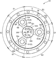
ここで、図1に示すように、回転軸C1方向におけるキャリア3の第2軸方向端面32A側には、図略の相手側部材に対してキャリア3の回転を伝達する出力軸部100が設けられている。
Here, as shown in FIG. 1, on the second
出力軸部100の一部は、キャリア3における第2部材32の中央孔32cに圧入されており、これにより出力軸部100がキャリア3に固定されている。出力軸部100の残部は、回転軸C1方向における第2軸方向端面32Aの外側に突出している。これにより、出力軸部100は、キャリア3の回転に応じて回転軸C1を軸心として回転し、この回転が第2軸方向端面32A側に配置された図略の相手側部材に伝達されることになる。
A part of the
ここで、図3〜図5を参照しながら、キャリア3における中央孔32cの内周面32dの形状、および当該中央孔32cに圧入される出力軸部100の形状について、詳細に説明する。
Here, the shape of the inner
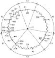
図3には、回転軸C1の中心とした径方向において中央孔32cとクランク軸孔32eとが対向する領域である第1領域E1を示すとともに、当該径方向において中央孔32cとクランク軸孔32eとが対向しない領域である第2領域E2を示している。具体的には、回転軸C1を中心として各クランク軸孔42cに接線を引いた場合に、当該各クランク軸孔42cを含む接線間の領域が第1領域E1であり、第1領域E1を除く接線間の領域が第2領域である。
FIG. 3 shows a first region E1 in which the
本実施形態では、キャリア3の第2部材32には、3つのクランク軸孔32eが回転軸C1を中心とした周方向に並んで形成されているため、3つの第1領域E1と3つの第2領域E2とが当該周方向に並んでいる。
In the present embodiment, three
図3に示すように、中央孔32cの内周面32dは、凹凸部300と、当該周方向に沿って滑らかに延びるとともに凹凸部300に連続する曲面400と、を有している。本実施形態では、中央孔32cの内周面32dは、3つの凹凸部300と3つの曲面400とを有しており、周方向において凹凸部300と曲面400とが交互に連続することにより、略円状をなしている。
As shown in FIG. 3, the inner
ここで、図4は、図3に示す中央孔32cの拡大図である。図4に示すように、中央孔32cは、第1領域E1に含まれる第1部位R1と、当該第1部位R1に対して周方向に連続する第2部位R2と、を有している。中央孔32cは、第1部位R1と第2部位R2とが周方向において交互に連続しており、これにより略円形状をなしている。
Here, FIG. 4 is an enlarged view of the
凹凸部300は、第2部位R2に形成されている。具体的に、本実施形態では、3つの凹凸部300のそれぞれが、3つの第2部位R2のそれぞれにのみ形成されている。このため、凹凸部300は、第1部位R1には形成されておらず、当該第1部位R1は周方向に沿って滑らかに延びる曲面400となっている。
The
なお、曲面400は、凹凸部300に繋がるため、凹凸部300が第2部位R2の一部にのみ形成されている場合には、曲面400の一部が第2部位R2まで延在していてもよい。
Since the
凹凸部300は、最外面301と、最内面302と、側面303と、を有しており、第2領域E2において当該側面303に曲面400が繋がっている。
The
最外面301は、凹凸部300のうち径方向において回転軸C1から最も遠い面である。本実施形態における最外面301は、本発明における最外部に相当する。凹凸部300には、複数の最外面301が含まれている。本実施形態では、各最外面301は、周方向に沿って滑らかに延びている。
The
最内面302は、凹凸部300のうち径方向において回転軸C1に最も近い面である。本実施形態における最内面302は、本発明における最内部に相当する。凹凸部300には、複数の最内面302が含まれている。各最内面302は、周方向において互いに隣り合う最外面301の間の領域に位置している。本実施形態では、各最内面302は、周方向に沿って滑らかに延びている。
The
側面303は、周方向に交差する面であって、当該周方向において互いに隣り合う最外面301と最内面302とを繋いでいる。凹凸部300には、複数の側面303が含まれている。本実施形態では、凹凸部300の全体が第2部位R2に形成されているため、複数の側面303も第2部位R2に形成されている。
The
各側面303は、径方向に対して傾斜している。具体的に、最外面301の両端部に繋がる2つの曲面は、径方向に対して互いに反対向きに傾斜している。このため、凹凸部300のうち最外面301と当該最外面301の両端部に繋がる2つの曲面とがなす部位は、径方向の外側に向かって凹むテーパ形状をなしている。
Each
各側面303は、径方向において、最も内側に位置する内端303aと、最も外側に位置する外端303bと、を含んでいる。そして、内端303aは、周方向における最内面302の端部に繋がっており、外端303bは、周方向における最外面301の端部に繋がっている。
Each
各側面303のうち、周方向において最も第1部位R1に近い側面303の外端303bは、曲面400に繋がっている。
Out of each
本実施形態では、第2領域E2にて周方向において互いに隣り合う側面303の間の長さL2は、第1領域E1にて周方向に沿って延びる曲面400の長さL1よりも短い。
In the present embodiment, the length L2 between the side surfaces 303 adjacent to each other in the circumferential direction in the second region E2 is shorter than the length L1 of the
また、本実施形態では、第1領域E1に位置する中央孔32cの半径r1は、第2領域E2に位置する中央孔32cの最大半径r2と同じ長さに設定されている。半径r1は、回転軸C1から曲面400までの長さであり、最大半径r2は、回転軸C1から最外面301までの長さである。なお、半径r1は、最大半径r2と同じ長さでなくともよく、最大半径r2以上の長さであればよい。
In the present embodiment, the radius r1 of the
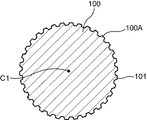
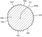
次に、図5には、出力軸部100のうち、図4に示す中央孔32cに圧入される部位の断面を示している。出力軸部100の径は、中央孔32cの圧入可能な程度の径に設定されている。出力軸部100の外周面100Aは、回転軸C1を中心とした周方向に沿って蛇行する凹凸101を含んでいる。本実施形態では、周方向において外周面100Aの全体に亘って一様に凹凸101が形成されている。
Next, FIG. 5 shows a cross section of a portion of the
なお、凹凸101は、周方向において外周面100Aの全体に亘って形成されていなくともよく、例えば中央孔32cの内周面32dにおける凹凸部300に対応する位置にのみ形成されてもよい。
In addition, the unevenness |
出力軸部100における外周面100Aの凹凸101は、キャリア3の中央孔32cにおける内周面32dの凹凸部300に対応する形状に形成されている。凹凸101の一部は、出力軸部100を中央孔32cの圧入した状態で、凹凸部300に噛み合っている。このため、中央孔32cの内周面32fにおける各側面303は、中央孔32cの圧入された出力軸部100の外周面100Aに対して周方向において接している。
The
以上のように、歯車装置X1では、キャリア3の第2部材32における中央孔32cに出力軸部100を圧入することにより当該出力軸部100をキャリア3に固定しているため、キャリア3と出力軸部100とを一体に形成する場合に比してコストの増大を抑止することができる。
As described above, in the gear device X1, since the
また、歯車装置X1では、中央孔32cの内周面32dは、出力軸部100の外周面100Aにおける凹凸101に噛み合う凹凸部300を有している。このため、内周面32dの凹凸部300に含まれる複数の側面303が回転軸C1を中心とした周方向において出力軸部100の外周面100Aに接する。これにより、キャリア3から出力軸部100への伝達トルクを十分に確保することができる。
Further, in the gear device X1, the inner
ところで、内周面32dの凹凸部300に噛み合うように出力軸部100が中央孔32cに圧入されると、当該凹凸部300に含まれる複数の側面303には、出力軸部100の外周面100Aが押し当たることになる。ここで、複数の側面303は、回転軸C1を中心とした径方向に対して傾斜している。このため、中央孔32cに出力軸部100を圧入した際に、当該出力軸部100から中央孔32cの内周面32dへと径方向の外側に加わる力は、複数の側面303が形成された領域ほど大きくなる。
By the way, when the
そこで、歯車装置X1では、キャリア3の基板部32aのうち中央孔32cとクランク軸孔32eとの間に位置する比較的薄肉の部位に対して強い力が加わることを抑止するため、内周面32dにうち、径方向において中央孔32cとクランク軸孔32eとが対向する第1領域E1に含まれる第1部位R1には複数の側面303を形成していない。そして、径方向において中央孔32cとクランク軸孔32eとが対向しない第2領域E2に含まれる第2部位R2に複数の側面303が形成されている。これにより、クランク軸孔32eの内周面32fに支持されるクランク軸5に対して強い力が加わることを抑止でき、当該クランク軸5の回転に支障をきたす可能性を低減できる。
Therefore, in the gear device X1, in order to suppress a strong force from being applied to a relatively thin portion located between the
さらに、歯車装置X1では、回転軸C1を中心とした周方向に沿って延びる曲面400(第1部位R1)が、当該曲面400に最も近い側に位置する側面303の外端303bに繋がっている。これにより、第1領域E1における中央孔32cの半径r1が第2領域E2における中央孔32cの最大半径r2以上に設定されている。このため、出力軸部100の外周面100Aにおける凹凸101が周方向の全域に亘って一様な形状であったとしても、当該出力軸部100を中央孔32cに圧入することが可能である。そのため、中央孔32cの凹凸部300に合わせて出力軸部100の凹凸101を形成する必要がなく、従来の出力軸部100をそのまま用いることが可能である。
Further, in the gear device X1, the curved surface 400 (first portion R1) extending along the circumferential direction around the rotation axis C1 is connected to the
<第2実施形態>
次に、第2実施形態に係る歯車装置X1について図6および図7を参照しながら説明する。なお、本実施形態では、第1実施形態と異なる部分についてのみ説明を行い、第1実施形態と同じ構造、作用及び効果の説明は省略する。
Second Embodiment
Next, the gear device X1 according to the second embodiment will be described with reference to FIGS. In the present embodiment, only parts different from the first embodiment will be described, and descriptions of the same structure, operation, and effect as those of the first embodiment will be omitted.
図6に示すように、第2実施形態の歯車装置X1は、中央孔32cの内周面32dの形状において第1実施形態の歯車装置X1とは異なる。
As shown in FIG. 6, the gear device X1 of the second embodiment is different from the gear device X1 of the first embodiment in the shape of the inner
具体的には、第2実施形態では、第1領域E1において周方向に滑らかに延びる曲面400は、周方向において当該曲面400に最も近い側面303の内端303aに繋がっている。このため、第2実施形態では、第1領域E1における中央孔32cの半径は、第2領域E2における中央孔32cの最大半径よりも小さくなっている。
Specifically, in the second embodiment, the
ここで、図7には、出力軸部100のうち図6の中央孔32cに圧入される部位の断面を示している。図7に示すように、出力軸部100の外周面100Aは、周方向に沿って蛇行する凹凸101と、周方向に沿って滑らかに延びる曲面102と、を含んでいる。
Here, FIG. 7 shows a cross section of a portion of the
本実施形態では、外周面100Aには、中央孔32cの内周面32dにおける3つの凹凸部300に対応して3つの凹凸101が形成されているとともに3つの曲面400に対応して3つの曲面102が形成されている。すなわち、本実施形態では、3つの凹凸101と3つの曲面102とが、周方向において交互に連続している。これにより、凹凸101が凹凸部300に噛み合うように、出力軸部100が中央孔32cの圧入されることになる。
In the present embodiment, on the outer
第2実施形態に係る歯車装置X1では、曲面400(第1部位R1)は、回転軸C1を中心とした周方向に沿って延びるとともに側面303の内端303aに繋がっている。このため、曲面400が側面303の外端303bに繋がる場合に比べて、キャリア3のうち中央孔32cとクランク軸孔32eとの間の部位の厚みを大きくすることができる。このため、中央孔32cへの出力軸部100の圧入によってクランク軸5の回転に支障をきたす可能性をより低減できる。
In the gear device X1 according to the second embodiment, the curved surface 400 (first portion R1) extends along the circumferential direction around the rotation axis C1 and is connected to the
以上説明した本実施形態は、すべての点で例示であって制限的なものではないと考えられるべきである。本発明の範囲は、上記の実施形態の説明ではなく特許請求の範囲によって示され、さらに特許請求の範囲と均等の意味および範囲内でのすべての変更が含まれる。 The present embodiment described above should be considered as illustrative in all points and not restrictive. The scope of the present invention is shown not by the above description of the embodiment but by the scope of claims for patent, and further includes meanings equivalent to the scope of claims for patent and all modifications within the scope.
例えば、上記の実施形態では、凹凸部300の各側面303は、回転軸C1を中心とした径方向に対して傾斜しているが、これに限らない。例えば、各側面303は、径方向に沿って延びていてもよい。
For example, in the above-described embodiment, each
また、上記の実施形態では、凹凸部300は、回転軸C1を中心とした周方向において第2領域E2の略全域に亘って形成されているが、これに限らない。例えば、凹凸部300は、第2領域E2のうち、第1領域E1に近い両端の領域を除く中央領域にのみ形成されてもよい。
In the above-described embodiment, the concavo-
また、上記の実施形態では、凹凸部300は、最外面301、最内面302、および側面303を有する屈曲形状に形成されているが、これに限らない。例えば、凹凸部300は、周方向に沿って蛇行する滑らかな曲線形状をなしていてもよい。この場合、当該凹凸部300のうち最も回転軸C1から遠い点が最外部になるとともに、凹凸部300のうち最も回転軸C1に近い点が最内部になり、当該最外部と最内部とを繋ぐ滑らかな曲線部分が側面303となる。
In the above embodiment, the
C1 回転軸
R1 第1部位
R2 第2部位
X1 歯車装置
3 キャリア
5 クランク軸
32c 中央孔
32d 中央孔の内周面
32e クランク軸孔
32f クランク軸孔
100 出力軸部
100A 出力軸部の外周面
101 凹凸
300 凹凸部
301 最外面(最外部)
302 最内面(最内部)
303 側面
303a 内端
303b 外端
400 曲面
C1 Rotating shaft R1 First part R2 Second part
302 innermost surface (innermost)
303
Claims (4)
前記クランク軸孔の内周面に支持されており、前記回転軸を中心として外筒に対して前記キャリアを相対的に回転させるクランク軸と、を備える歯車装置であって、
前記中央孔の内周面は、前記出力軸部の前記凹凸に噛み合う凹凸部を有しており、
前記凹凸部は、前記径方向における最も外側に位置する複数の最外部と、当該径方向における最も内側に位置する複数の最内部と、前記最外部と前記最内部とを繋ぐとともに前記前記径方向に対して傾斜した複数の側面と、を含んでおり、
前記中央孔の内周面は、前記径方向において、前記中央孔と前記クランク軸孔とが対向する領域に含まれる第1部位と、前記周方向において前記第1部位に隣接する第2部位と、を有しており、
前記各側面は、前記第2部位に形成されている、歯車装置。 A center hole provided along the rotation axis while an output shaft portion having irregularities formed on the outer peripheral surface is press-fitted, and a crankshaft provided so as to be aligned with the center hole in a radial direction around the rotation axis A carrier having pores;
A crankshaft supported by an inner peripheral surface of the crankshaft hole, and a crankshaft that rotates the carrier relative to an outer cylinder around the rotating shaft,
The inner peripheral surface of the central hole has an uneven portion that meshes with the uneven portion of the output shaft portion,
The concavo-convex portion connects the plurality of outermost portions located on the outermost side in the radial direction, the plurality of innermost portions located on the innermost side in the radial direction, the outermost portion and the innermost portion, and the radial direction. A plurality of side surfaces inclined with respect to
The inner peripheral surface of the central hole includes a first part included in a region where the central hole and the crankshaft hole face each other in the radial direction, and a second part adjacent to the first part in the circumferential direction. , And
Each said side is a gear apparatus currently formed in the said 2nd site | part.
Priority Applications (3)
| Application Number | Priority Date | Filing Date | Title |
|---|---|---|---|
| JP2016037520A JP6898708B2 (en) | 2016-02-29 | 2016-02-29 | Gear device |
| KR1020170020033A KR20170101784A (en) | 2016-02-29 | 2017-02-14 | Gear apparatus |
| CN201710092455.4A CN107131255A (en) | 2016-02-29 | 2017-02-21 | Geared system |
Applications Claiming Priority (1)
| Application Number | Priority Date | Filing Date | Title |
|---|---|---|---|
| JP2016037520A JP6898708B2 (en) | 2016-02-29 | 2016-02-29 | Gear device |
Publications (2)
| Publication Number | Publication Date |
|---|---|
| JP2017155772A true JP2017155772A (en) | 2017-09-07 |
| JP6898708B2 JP6898708B2 (en) | 2021-07-07 |
Family
ID=59721083
Family Applications (1)
| Application Number | Title | Priority Date | Filing Date |
|---|---|---|---|
| JP2016037520A Active JP6898708B2 (en) | 2016-02-29 | 2016-02-29 | Gear device |
Country Status (3)
| Country | Link |
|---|---|
| JP (1) | JP6898708B2 (en) |
| KR (1) | KR20170101784A (en) |
| CN (1) | CN107131255A (en) |
Citations (6)
| Publication number | Priority date | Publication date | Assignee | Title |
|---|---|---|---|---|
| JPH0654924U (en) * | 1993-01-12 | 1994-07-26 | マツダ株式会社 | Gearbox synchronizer |
| JPH08506647A (en) * | 1993-02-06 | 1996-07-16 | ジー・ケー・エヌ・オートモーティヴ・アクチエンゲゼルシャフト | Torque transmission structure |
| JPH11108070A (en) * | 1997-10-03 | 1999-04-20 | Toyota Motor Corp | Fitting structure and fitting method for shaft members |
| JP2008196650A (en) * | 2007-02-15 | 2008-08-28 | Nsk Ltd | Universal joint, steering device using it, and electric power steering device |
| JP2011247364A (en) * | 2010-05-27 | 2011-12-08 | Sumitomo Heavy Ind Ltd | Sliding structure of gear and shaft, and retainer of roller bearing |
| JP2013035005A (en) * | 2011-08-05 | 2013-02-21 | O-Oka Corp | Inner spline gear with special intermittent tooth |
Family Cites Families (4)
| Publication number | Priority date | Publication date | Assignee | Title |
|---|---|---|---|---|
| JP4918052B2 (en) * | 2008-02-08 | 2012-04-18 | ナブテスコ株式会社 | Eccentric oscillating gear unit |
| JP5425742B2 (en) * | 2010-10-13 | 2014-02-26 | 住友重機械工業株式会社 | Planetary gear reducer |
| CN204175931U (en) * | 2014-10-30 | 2015-02-25 | 北京汽车动力总成有限公司 | The adjective-centre structure of a kind of gear and axle |
| CN104455227B (en) * | 2014-11-26 | 2017-02-01 | 合肥耀辉太阳能热力工程科技有限公司 | Reduction gear with group drive of involute gear and cycloid gear |
-
2016
- 2016-02-29 JP JP2016037520A patent/JP6898708B2/en active Active
-
2017
- 2017-02-14 KR KR1020170020033A patent/KR20170101784A/en not_active Application Discontinuation
- 2017-02-21 CN CN201710092455.4A patent/CN107131255A/en active Pending
Patent Citations (6)
| Publication number | Priority date | Publication date | Assignee | Title |
|---|---|---|---|---|
| JPH0654924U (en) * | 1993-01-12 | 1994-07-26 | マツダ株式会社 | Gearbox synchronizer |
| JPH08506647A (en) * | 1993-02-06 | 1996-07-16 | ジー・ケー・エヌ・オートモーティヴ・アクチエンゲゼルシャフト | Torque transmission structure |
| JPH11108070A (en) * | 1997-10-03 | 1999-04-20 | Toyota Motor Corp | Fitting structure and fitting method for shaft members |
| JP2008196650A (en) * | 2007-02-15 | 2008-08-28 | Nsk Ltd | Universal joint, steering device using it, and electric power steering device |
| JP2011247364A (en) * | 2010-05-27 | 2011-12-08 | Sumitomo Heavy Ind Ltd | Sliding structure of gear and shaft, and retainer of roller bearing |
| JP2013035005A (en) * | 2011-08-05 | 2013-02-21 | O-Oka Corp | Inner spline gear with special intermittent tooth |
Also Published As
| Publication number | Publication date |
|---|---|
| CN107131255A (en) | 2017-09-05 |
| JP6898708B2 (en) | 2021-07-07 |
| KR20170101784A (en) | 2017-09-06 |
Similar Documents
| Publication | Publication Date | Title |
|---|---|---|
| JP6261761B2 (en) | Wave generator and wave gear device | |
| JP2010091073A (en) | Eccentric oscillation type gear device | |
| TWI661141B (en) | Gear device | |
| JP6194241B2 (en) | Gear transmission | |
| KR20220150249A (en) | Gear device | |
| WO2013140721A1 (en) | Eccentrically oscillating gear device | |
| JP6440466B2 (en) | Eccentric oscillating gear unit | |
| JP2016130536A (en) | Gear device | |
| JP6049935B1 (en) | Joint yoke for universal joint and universal joint | |
| US20070117675A1 (en) | Washer and planetary gear set having the same | |
| JP2017155772A (en) | Gear device | |
| JP2020112262A (en) | Speed reducer | |
| JP6563640B2 (en) | Eccentric oscillating gear unit | |
| JP2016164431A (en) | Planetary roller type power transmission device | |
| JP6097045B2 (en) | Traction drive mechanism | |
| JP5312373B2 (en) | Differential pressure relief structure of differential case in differential gear | |
| JP6857688B2 (en) | Eccentric swing type gear device | |
| JP6992141B2 (en) | Gear device | |
| JP7469863B2 (en) | Toroidal Continuously Variable Transmission | |
| TWI851725B (en) | Bearings and reducers | |
| JP2012013207A (en) | Tripod type constant velocity joint | |
| JP2010032000A (en) | Eccentrically oscillating type gear device and roller bearing | |
| JP2008069903A (en) | Tripod type constant velocity joint and its roller unit | |
| JP2015021555A (en) | Eccentric oscillation type gear device | |
| JP2021089076A (en) | Gear device |
Legal Events
| Date | Code | Title | Description |
|---|---|---|---|
| A621 | Written request for application examination |
Free format text: JAPANESE INTERMEDIATE CODE: A621 Effective date: 20190128 |
|
| A131 | Notification of reasons for refusal |
Free format text: JAPANESE INTERMEDIATE CODE: A131 Effective date: 20200114 |
|
| A521 | Request for written amendment filed |
Free format text: JAPANESE INTERMEDIATE CODE: A523 Effective date: 20200312 |
|
| A131 | Notification of reasons for refusal |
Free format text: JAPANESE INTERMEDIATE CODE: A131 Effective date: 20200908 |
|
| A521 | Request for written amendment filed |
Free format text: JAPANESE INTERMEDIATE CODE: A523 Effective date: 20201104 |
|
| TRDD | Decision of grant or rejection written | ||
| A01 | Written decision to grant a patent or to grant a registration (utility model) |
Free format text: JAPANESE INTERMEDIATE CODE: A01 Effective date: 20210601 |
|
| A61 | First payment of annual fees (during grant procedure) |
Free format text: JAPANESE INTERMEDIATE CODE: A61 Effective date: 20210611 |
|
| R151 | Written notification of patent or utility model registration |
Ref document number: 6898708 Country of ref document: JP Free format text: JAPANESE INTERMEDIATE CODE: R151 |
|
| R250 | Receipt of annual fees |
Free format text: JAPANESE INTERMEDIATE CODE: R250 |