JP2017154736A - Transaxle device of vehicle - Google Patents
Transaxle device of vehicle Download PDFInfo
- Publication number
- JP2017154736A JP2017154736A JP2017065969A JP2017065969A JP2017154736A JP 2017154736 A JP2017154736 A JP 2017154736A JP 2017065969 A JP2017065969 A JP 2017065969A JP 2017065969 A JP2017065969 A JP 2017065969A JP 2017154736 A JP2017154736 A JP 2017154736A
- Authority
- JP
- Japan
- Prior art keywords
- gear
- shaft
- drive shaft
- gear set
- engine
- Prior art date
- Legal status (The legal status is an assumption and is not a legal conclusion. Google has not performed a legal analysis and makes no representation as to the accuracy of the status listed.)
- Pending
Links
Images


Classifications
-
- Y—GENERAL TAGGING OF NEW TECHNOLOGICAL DEVELOPMENTS; GENERAL TAGGING OF CROSS-SECTIONAL TECHNOLOGIES SPANNING OVER SEVERAL SECTIONS OF THE IPC; TECHNICAL SUBJECTS COVERED BY FORMER USPC CROSS-REFERENCE ART COLLECTIONS [XRACs] AND DIGESTS
- Y02—TECHNOLOGIES OR APPLICATIONS FOR MITIGATION OR ADAPTATION AGAINST CLIMATE CHANGE
- Y02T—CLIMATE CHANGE MITIGATION TECHNOLOGIES RELATED TO TRANSPORTATION
- Y02T10/00—Road transport of goods or passengers
- Y02T10/60—Other road transportation technologies with climate change mitigation effect
- Y02T10/62—Hybrid vehicles
Abstract
Description
本発明は車両のトランスアクスル装置に関するものである。 The present invention relates to a transaxle device for a vehicle.
例えばハイブリッド車やプラグインハイブリッド車のように、複数の走行駆動源を備えた車両が知られている。ハイブリッド車やプラグインハイブリッド車は、エンジン及び電動モータを走行駆動源として備えている。そして、このようなハイブリッド車等において、エンジンと電動モータの両方で同時に駆動輪を駆動するパラレル走行モードが可能な車両が開発されている。 For example, vehicles having a plurality of travel drive sources such as hybrid vehicles and plug-in hybrid vehicles are known. Hybrid vehicles and plug-in hybrid vehicles include an engine and an electric motor as travel driving sources. In such a hybrid vehicle or the like, a vehicle capable of a parallel traveling mode in which driving wheels are driven simultaneously by both an engine and an electric motor has been developed.
上記のようなハイブリッド車において、エンジンと電動モータは、例えば車両の前部に左右方向に並べて配置されており、前輪を駆動するドライブシャフトに接続するトランスアクスル装置がエンジンと電動モータとの間に備えられている車両がある。
例えば特許文献1の図1に記載されたトランスアクスル装置は、エンジンとモータとの間に配置され、エンジンの駆動軸とモータの駆動軸とドライブシャフトに差動装置を介して接続される出力軸(アイドラー軸3)とが互いに平行に配置されている。
In the hybrid vehicle as described above, for example, the engine and the electric motor are arranged side by side in the left-right direction at the front portion of the vehicle, and the transaxle device connected to the drive shaft that drives the front wheels is interposed between the engine and the electric motor. There are vehicles equipped.
For example, the transaxle device described in FIG. 1 of Patent Document 1 is disposed between an engine and a motor, and is connected to the engine drive shaft, the motor drive shaft, and the drive shaft via a differential device. (Idler shaft 3) are arranged in parallel to each other.
上記特許文献1のトランスアクスル装置では、エンジンの駆動軸と出力軸とが2個のギヤからなるギヤ組を介して動力を伝達し、モータの駆動軸と出力軸とが2個のギヤからなる他のギヤ組を介して動力が伝達する構成になっている。
したがって、エンジンとモータの両方を駆動したときに、エンジンの駆動軸及びモータの駆動軸が同一方向に回転する。これにより、エンジンの作動により車体が受ける反動トルクとモータの作動により車体が受ける反動トルクとが合成されて車体の振動を増加させる虞がある。
また、ハイブリッド車においては、EV走行モード、パラレル走行モード、シリーズ走行モードといった各種走行モードが可能な、部品点数を抑えたトランスアクスル装置が要求されている。
In the transaxle device disclosed in Patent Document 1, power is transmitted through a gear set including an engine drive shaft and an output shaft consisting of two gears, and the motor drive shaft and the output shaft include two gears. Power is transmitted through another gear set.
Therefore, when both the engine and the motor are driven, the engine drive shaft and the motor drive shaft rotate in the same direction. As a result, the reaction torque received by the vehicle body by the operation of the engine and the reaction torque received by the vehicle body by the operation of the motor may be combined to increase the vibration of the vehicle body.
Further, in a hybrid vehicle, there is a demand for a transaxle device capable of various driving modes such as an EV driving mode, a parallel driving mode, and a series driving mode with a reduced number of parts.
本発明はこのような問題点を解決するためになされたもので、エンジンと電動機の同時作動時における車体の揺れを低減可能にするとともに、部品点数を抑え、各種走行モードが可能な車両のトランスアクスル装置を提供することにある。 The present invention has been made to solve such a problem, and it is possible to reduce the vibration of the vehicle body during simultaneous operation of the engine and the electric motor, reduce the number of parts, and perform various driving modes. It is to provide an axle device.
上記目的を達成するため、請求項1の発明は、車両に搭載されたエンジンの駆動軸と同軸配置され、駆動軸に接続される第1の駆動軸と、第1の駆動軸と平行に配置され、車両の走行駆動軸に差動装置を介して動力を伝達する出力軸と、出力軸と平行に配置され、車両に搭載されたバッテリから電力を供給されて駆動する電動モータとして作動する第1の電動機に接続される第2の駆動軸と、第2の駆動軸と平行もしくは同軸に配置され、発電機として作動する車両に搭載された第2の電動機に接続される第3の駆動軸と、複数のギヤを噛み合わせて構成され第1の駆動軸と出力軸との間で動力を伝達する第1のギヤ組と、複数のギヤにより構成され第2の駆動軸と出力軸との間で動力を伝達する第2のギヤ組と、複数のギヤを噛み合わせて構成され第1の駆動軸と第3の駆動軸との間で動力を伝達する第3のギヤ組と、を備えた車両のトランスアクスル装置であって、第1のギヤ組は、第1の駆動軸に設けられたアイドラギヤと、出力軸に設けられアイドラギヤに噛み合う第1のギヤとにより構成され、第2のギヤ組は、第2の駆動軸に設けられた第2のギヤと、アイドラギヤと第1のギヤとにより構成され、第1のギヤとアイドラギヤとが噛み合い、アイドラギヤと第2のギヤとが噛み合うように構成され、第1のギヤ組と第2のギヤ組はアイドラギヤを共用すると共に、第1のギヤ組を構成するギヤの噛み合い数は、奇数及び偶数のうちいずれか一方であり、第2のギヤ組を構成するギヤの噛み合い数は、奇数及び偶数のうちの他方であることを特徴とする。 In order to achieve the above object, the invention of claim 1 is arranged coaxially with a drive shaft of an engine mounted on a vehicle, and arranged in parallel with the first drive shaft connected to the drive shaft. An output shaft that transmits power to the travel drive shaft of the vehicle via a differential, and an electric motor that is arranged in parallel with the output shaft and that is driven by being supplied with electric power from a battery mounted on the vehicle. A second drive shaft connected to one electric motor, and a third drive shaft arranged in parallel or coaxially with the second drive shaft and connected to a second electric motor mounted on a vehicle operating as a generator A first gear set configured by meshing a plurality of gears and transmitting power between the first drive shaft and the output shaft, and a second drive shaft and output shaft configured by a plurality of gears. The second gear set that transmits power between them and the multiple gears And a third gear set configured to transmit power between the first drive shaft and the third drive shaft, wherein the first gear set includes the first gear set and the third gear set. An idler gear provided on the drive shaft and a first gear provided on the output shaft and meshing with the idler gear. The second gear set includes a second gear provided on the second drive shaft, and an idler gear. The first gear and the idler gear mesh with each other, and the idler gear and the second gear mesh with each other. The first gear set and the second gear set share the idler gear. The meshing number of the gears constituting the first gear set is either odd or even, and the meshing number of the gears constituting the second gear set is the other of the odd or even numbers. It is characterized by.
また、請求項2の発明は、請求項1において、アイドラギヤは、第1のエンジン軸に対して、動力断接手段を介して動力の伝達を断接切り換え可能に設けられていることを特徴とする。
また、請求項3の発明は、請求項2において、動力断接手段は同期噛み合い装置であることを特徴とする。
The invention according to
According to a third aspect of the present invention, in the second aspect, the power connection / disconnection means is a synchronous meshing device.
また、請求項4の発明は、請求項1から3のいずれか1項において、第3のギヤ組を構成するギヤの噛み合い数が奇数であることを特徴とする。
また、請求項5の発明は、請求項4において、第3の駆動軸は、第2の駆動軸と軸受け手段を介して相互回転可能に同軸上に配置されるとともに、第1のギヤ組を構成するギヤの噛み合い数は奇数であり、第2のギヤ組を構成するギヤの噛み合い数は偶数であることを特徴とする。
According to a fourth aspect of the present invention, in any one of the first to third aspects, the number of meshing gears constituting the third gear set is an odd number.
According to a fifth aspect of the present invention, in the fourth aspect, the third drive shaft is coaxially disposed so as to be mutually rotatable via the second drive shaft and the bearing means, and the first gear set is provided. The number of meshing gears is an odd number, and the number of meshing gears constituting the second gear set is an even number.
また、請求項6の発明は、請求項4または5において、出力軸には、差動装置に動力を伝達するファイナルギヤが備えられ、第3のギヤ組に含まれる第3のギヤとファイナルギヤとが第1の駆動軸の軸線方向でオーバーラップして配置されることを特徴とする。 According to a sixth aspect of the present invention, in the fourth or fifth aspect, the output shaft is provided with a final gear for transmitting power to the differential, and the third gear and the final gear included in the third gear set are provided. Are overlapped in the axial direction of the first drive shaft.
本発明の請求項1の車両のトランスアクスル装置では、エンジンの駆動軸に接続される第1の駆動軸と出力軸との間で動力を伝達する第1のギヤ組のギヤの噛み合い数が奇数及び偶数のうちいずれか一方であり、第1の電動機により駆動される第2の駆動軸と出力軸との間で動力を伝達する第2のギヤ組のギヤの噛み合い数が奇数及び偶数のうちの他方であるので、出力軸を介して第1の駆動軸と第2の駆動軸とは逆方向に回転する。したがって、エンジンと第1の電動機が同時に作動しこれらの回転速度が変化したときに、エンジンにより車体が受ける反動トルクと、第1の電動機により車体が受ける反動トルクとが相殺され、車体(パワープラント)の揺れを低減させることができる。 In the transaxle device for a vehicle according to claim 1 of the present invention, the number of meshing gears of the first gear set for transmitting power between the first drive shaft connected to the drive shaft of the engine and the output shaft is an odd number. And even number, and the meshing number of the gears of the second gear set that transmits power between the second drive shaft driven by the first electric motor and the output shaft is an odd number or an even number. Therefore, the first drive shaft and the second drive shaft rotate in opposite directions via the output shaft. Accordingly, when the engine and the first electric motor operate simultaneously and their rotational speeds change, the reaction torque received by the vehicle body by the engine and the reaction torque received by the vehicle body by the first electric motor are offset, and the vehicle body (power plant ) Can be reduced.
特に、エンジン及び第1の電動機が車両に横置きで配置されている場合には、エンジン作動により発生するジャイロモーメントと第1の電動機の作動により発生するジャイロモーメントとが打ち消し合うことで、車両の旋回性能を向上させることができる。
更に、第1のギヤ組と第2のギヤ組は、アイドラギヤを共用しているので、ギヤの使用枚数を低減し、部品点数を低減させることができる。
In particular, when the engine and the first electric motor are arranged horizontally in the vehicle, the gyro moment generated by the operation of the engine and the gyro moment generated by the operation of the first electric motor cancel each other, thereby Turning performance can be improved.
Furthermore, since the first gear group and the second gear group share the idler gear, the number of used gears can be reduced and the number of parts can be reduced.
また、アイドラギヤに対して第1のギヤ及び第2のギヤを噛み合わせるように、エンジン軸、第1の駆動軸及び出力軸を配置すればよいので、これらの軸の配置の自由度を向上させることができる。
また、第1の駆動軸と第3の駆動軸とが第3のギヤ組を介して動力を伝達するので、エンジンにより第2の電動機を駆動することができる。
そして、エンジンにより車両の走行駆動軸を駆動するエンジン直結モード、電動モータにより走行駆動軸を駆動するEV走行モード、エンジン及び電動モータの両方で走行駆動軸を駆動するパラレル走行モード、電動モータにより走行駆動軸を駆動するとともにエンジンによって発電機を駆動するシリーズ走行モードが可能となるので、ハイブリッド車に好適なトランスアクスル装置を提供することができる。
本発明の請求項2の車両のトランスアクスル装置では、動力断接手段によりアイドラギヤと第1の駆動軸とを接続することで、エンジンから出力軸に動力を伝達することができる。また、動力断接手段によりアイドラギヤと第1の駆動軸との接続を切り離すことで、エンジンの連れ回りによるエネルギー効率の低下を防止しつつ第1の電動機から出力軸に動力を伝達することができる。このように、動力断接手段により断接を切換えることで、エンジンによる走行駆動と第1の電動機による走行駆動の切り換えを可能にして、車両のエネルギー効率を向上させることができる。
In addition, since the engine shaft, the first drive shaft, and the output shaft may be arranged so that the first gear and the second gear are engaged with the idler gear, the degree of freedom in arranging these shafts is improved. be able to.
Further, since the first drive shaft and the third drive shaft transmit power through the third gear set, the engine can drive the second electric motor.
Then, an engine direct connection mode in which the travel drive shaft of the vehicle is driven by the engine, an EV travel mode in which the travel drive shaft is driven by the electric motor, a parallel travel mode in which the travel drive shaft is driven by both the engine and the electric motor, and travel by the electric motor. Since a series travel mode in which the drive shaft is driven and the generator is driven by the engine is possible, a transaxle device suitable for a hybrid vehicle can be provided.
In the transaxle device for a vehicle according to
本発明の請求項3の車両のトランスアクスル装置では、動力断接手段が同期噛み合い装置であるので、アイドラギヤと第1の駆動軸との接続を滑らかに行うことができるとともにコンパクトに構成することができる。更には一般的な湿式多板クラッチによる動力伝達手段に比べて非結合時のフリクションを抑えて燃費を向上させるとともに、動力断接手段の切り換え作動に必要とする消費エネルギーを低減させることができる。 In the transaxle device for a vehicle according to claim 3 of the present invention, since the power connecting / disconnecting means is a synchronous meshing device, the idler gear and the first drive shaft can be smoothly connected and can be configured compactly. it can. Furthermore, compared with a power transmission means using a general wet multi-plate clutch, friction at the time of non-engagement can be suppressed to improve fuel efficiency, and energy consumption required for switching operation of the power connection / disconnection means can be reduced.
本発明の請求項4の車両のトランスアクスル装置では、第3のギヤ組のギヤの噛み合い数が奇数であるので、第1の駆動軸と第3の駆動軸とが逆方向に回転する。これにより、エンジンと第2の電動機が同時に作動したときに、エンジンにより車体が受ける反動トルクと、第2の電動機により車体が受ける反動トルクとが相殺され、車体(パワープラント)の揺れを更に軽減することができる。 In the transaxle device for a vehicle according to claim 4 of the present invention, since the meshing number of the gears of the third gear set is an odd number, the first drive shaft and the third drive shaft rotate in opposite directions. As a result, when the engine and the second electric motor are operated simultaneously, the reaction torque received by the vehicle body by the engine and the reaction torque received by the vehicle body by the second electric motor cancel each other, further reducing the shaking of the vehicle body (power plant). can do.
本発明の請求項5の車両のトランスアクスル装置では、第1のギヤ組を構成するギヤの噛み合い数は奇数であり、第2のギヤ組を構成するギヤの噛み合い数は偶数であるので、第2の駆動軸と第3の駆動軸とは同一方向に回転する。これにより、第2の駆動軸と第3の駆動軸との回転速度差を低減させることができ、第2の駆動軸と第3の駆動軸との間に介装される軸受け手段の寿命を向上させることができる。
In the transaxle device for a vehicle according to
また、第2の駆動軸と第3の駆動軸とが同軸上に配置されるので、第1の電動機と第2の電動機を隣接して配置し、これらの電動機のハウジングを共通化してコンパクトに構成することができる。
本発明の請求項6の車両のトランスアクスル装置では、第3のギヤ組を構成する第3のギヤとファイナルギヤとが第1の駆動軸の軸線方向でオーバーラップして配置されるので、トランスアクスル装置のギヤ列数を抑制して軸線方向の寸法を低減させることができる。
In addition, since the second drive shaft and the third drive shaft are arranged coaxially, the first motor and the second motor are arranged adjacent to each other, and the housings of these motors are made common and compact. Can be configured.
In the transaxle device for a vehicle according to claim 6 of the present invention, the third gear and the final gear constituting the third gear set are arranged so as to overlap in the axial direction of the first drive shaft. The number of gear trains of the axle device can be suppressed, and the axial dimension can be reduced.
以下、本発明の実施形態を添付図面に基づき説明する。
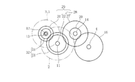
図1は、本発明の第1の実施形態のトランスアクスル装置の模式図である。図2は、第1の実施形態のトランスアクスル装置におけるギヤの噛み合い状態を示す説明図である。なお、図2は、トランスアクスル装置の側方から見た図である。
本発明の第1の実施形態に係るトランスアクスル装置1は、走行駆動源としてエンジン2と電動モータ3(第1の電動機)を横置きに搭載したハイブリッド車(以下、車両という)に採用される。本実施形態の車両は、車両の前部にエンジン2と電動モータ3を搭載し、前車軸であるドライブシャフト4(走行駆動軸)を駆動するFF車である。
Hereinafter, embodiments of the present invention will be described with reference to the accompanying drawings.
FIG. 1 is a schematic diagram of a transaxle device according to a first embodiment of the present invention. FIG. 2 is an explanatory view showing a gear meshing state in the transaxle device of the first embodiment. FIG. 2 is a side view of the transaxle device.
The transaxle device 1 according to the first embodiment of the present invention is employed in a hybrid vehicle (hereinafter referred to as a vehicle) in which an
図1に示すように、本実施形態に係る車両では、エンジン2と電動モータ3は、トランスアクスル装置1を挟んで車両の左右方向に離間して配置されている。また、電動モータ3の車両左方には、発電機5(第2の電動機)が隣接して備えられている。なお、エンジン2、電動モータ3、トランスアクスル装置1及び発電機5は、車両のパワープラントを構成し、車体に一体的に支持されている。
As shown in FIG. 1, in the vehicle according to the present embodiment, the
トランスアクスル装置1は、ドライブプレート10を介して、エンジン2のクランクシャフト(駆動軸)に接続されるエンジン軸11(第1の駆動軸)と、電動モータ3により駆動されるモータ軸12(第2の駆動軸)、発電機5の駆動軸である発電機軸13(第3の駆動軸)及び出力軸14を備えている。
エンジン軸11、モータ軸12、発電機軸13、及び出力軸14は、互いに平行に車両左右方向に延びるように配置されている。
The transaxle device 1 includes an engine shaft 11 (first drive shaft) connected to a crankshaft (drive shaft) of the
The
エンジン軸11の車両右方端部に、ドライブプレート10が接続されている。
モータ軸12は、中空状に形成され、その内部に発電機軸13が同軸上に配置されている。発電機軸13は、モータ軸12よりも長く形成され、両端部が夫々モータ軸12よりも外方に突出している。モータ軸12の両端部内部には、モータ軸12と発電機軸13との間に夫々ベアリング15(軸受け手段)が備えられている。ベアリング15は、モータ軸12と発電機軸13とを互いに回転可能に支持している。モータ軸12及び発電機軸13は、夫々車両左方端部がトランスアクスル装置1から突出しており、モータ軸12の車両左方端部近傍が電動モータ3に接続され、発電機軸13の車両左方端部近傍が発電機5に接続されている。
A
The
また、トランスアクスル装置1には、左右のドライブシャフト4に動力を配分する差動装置16が備えられている。
出力軸14は、その車両右方端部近傍に設けられたファイナルギヤ20を介して差動装置16に動力を伝達可能に構成されている。
エンジン軸11には、車両右方(エンジン2側)から順番に、エンジン軸固定ギヤ21(第3のギヤ)及びアイドラギヤ22が配置されている。
Further, the transaxle device 1 is provided with a
The
An engine shaft fixed gear 21 (third gear) and an
エンジン軸固定ギヤ21はエンジン軸11に固定され、エンジン軸11の回転に伴って回転する。アイドラギヤ22は、エンジン軸11に対して回転可能に支持されている。更に、エンジン軸11には、エンジン軸11とアイドラギヤ22とを接続及び切断とで切り換え可能なシンクロナイザ23(同期噛み合い装置、動力断接手段)が備えられている。シンクロナイザ23は、図示しないアクチュエータ等により切り換え操作可能となっている。
The engine
モータ軸12の車両右方端部近傍には、モータ軸固定ギヤ26(第2のギヤ)が備えられている。モータ軸固定ギヤ26は、モータ軸12に固定されており、モータ軸12とともに回転する構成になっている。更に、モータ軸固定ギヤ26とアイドラギヤ22とは噛み合うように、エンジン軸11の軸方向で一致するように配置されている。
また、出力軸14の車両左方端部近傍には、出力軸固定ギヤ27(第1のギヤ)が備えられている。出力軸固定ギヤ27は、出力軸14に固定されており、出力軸14とともに回転する構成になっている。更に、出力軸固定ギヤ27とアイドラギヤ22とは噛み合うように、エンジン軸11の軸方向で一致するように配置されている。なお、アイドラギヤ22と出力軸固定ギヤ27とは、第1のギヤ組28を構成している。即ちエンジン軸11と出力軸14とは、図1、2に示すように、2つのギヤ22、27からなり噛み合い数が1つである第1のギヤ組28を介して動力伝達可能に構成されている。ここで、噛み合い数とは、複数のギヤが動力を伝達することによって、ギヤの回転方向が切り換わる回数のことを表しており、ギヤ同士の歯と歯が接触する回数を表しているのではない。
A motor shaft fixed gear 26 (second gear) is provided in the vicinity of the vehicle right end portion of the
Further, an output shaft fixed gear 27 (first gear) is provided in the vicinity of the vehicle left end portion of the
また、モータ軸固定ギヤ26とアイドラギヤ22と出力軸固定ギヤ27とは、第2のギヤ組29を構成している。即ちモータ軸12と出力軸14とは、3つのギヤ26、22、27からなり噛み合い数が2つである第2のギヤ組29を介して動力伝達可能に構成されている。
発電機軸13の車両右方端部近傍には、発電機軸固定ギヤ31が備えられている。発電機軸固定ギヤ31は、発電機軸13に固定されており、発電機軸13とともに回転する構成になっている。更に、発電機軸固定ギヤ31とエンジン軸固定ギヤ21とは噛み合うように、エンジン軸11の軸方向で一致するように配置されている。なお、エンジン軸固定ギヤ21と発電機軸固定ギヤ31は、第3のギヤ組32を構成している。即ちエンジン軸11と発電機軸13とは、2つのギヤ21、31からなり噛み合い数が1つである第3のギヤ組32を介して常に動力伝達可能に構成されている。
Further, the motor shaft fixed
A generator
また、出力軸14に設けられたファイナルギヤ20とエンジン軸固定ギヤ21とは、噛み合っていないが、エンジン軸11の軸方向でオーバーラップするように配置されている。
以上のような構成により、本実施形態のトランスアクスル装置1では、エンジン軸11と発電機軸13とは第3のギヤ組32を介して常に動力伝達可能に構成され、モータ軸12と出力軸14とは第2のギヤ組29を介して常に動力伝達可能に構成されている。そして、エンジン軸11とアイドラギヤ22とが接続されないようにシンクロナイザ23を作動制御し、車両に搭載された図示しないバッテリから電力を供給して電動モータ3を駆動することで、当該電動モータ3により走行駆動するEV走行モードが可能となっている。なお、このとき電動モータ3の要求電力の増加やバッテリの充電率の低下に応じてエンジン2を駆動することで、エンジン2により発電機5を駆動して発電することができ、電動モータ3への電力供給やバッテリの充電が可能となり、よってシリーズ走行モードが可能となる。
Further, the
With the configuration as described above, in the transaxle device 1 of the present embodiment, the
また、シンクロナイザ23を作動制御してエンジン軸11とアイドラギヤ22とを接続することで、エンジン軸11と出力軸14とが第1のギヤ組28を介して動力が伝達可能となる。これにより、エンジン14により走行駆動するエンジン直結モードが可能となる。このとき、更に電動モータ3を駆動することで、エンジン2と電動モータ3の両方から出力軸14に動力が伝達されて走行駆動するパラレル走行モードが可能となる。
In addition, by controlling the operation of the
図3は、パラレル走行モード時におけるトランスアクスル装置1での各軸の回転方向を示す説明図である。
図3は、パラレル走行モードで車両を前進させる場合での、各軸の回転方向を示している。なお、以下、車両に前進させる場合でのドライブシャフト4の回転方向と同一の回転方向を正転、この正転と逆方向の回転方向を逆転という。
FIG. 3 is an explanatory diagram showing the rotation direction of each axis in the transaxle device 1 in the parallel traveling mode.
FIG. 3 shows the rotation direction of each axis when the vehicle is advanced in the parallel travel mode. Hereinafter, the rotation direction that is the same as the rotation direction of the drive shaft 4 when the vehicle is advanced is referred to as forward rotation, and the rotation direction opposite to the normal rotation is referred to as reverse rotation.
図3に示すように、車両を前進させる場合には、ドライブシャフト4が正転となり、出力軸14が逆転となる。
そして、モータ軸12と出力軸14との間で動力を伝達する第2のギヤ組29が3枚のギヤ26、22、27から構成されてその噛み合い数が2つであることから、モータ軸12は出力軸14と同方向の回転に、即ち逆転となる。また、エンジン軸11と出力軸14との間で動力を伝達する第1のギヤ組28が2枚のギヤ22、27から構成されて噛み合い数が1つであることから、エンジン軸11は出力軸14と逆方向の回転に、即ち正転となる。また、発電機軸13とエンジン軸11との間で動力を伝達する第3のギヤ組32が2枚のギヤ21、31から構成されて噛み合い数が1つであることから、発電機軸13はエンジン軸11と逆方向の回転に、即ち逆転となる。
As shown in FIG. 3, when the vehicle is advanced, the drive shaft 4 is rotated forward and the
Since the second gear set 29 for transmitting power between the
このように、パラレル走行モード時には、エンジン軸11は正転し、モータ軸12は逆転するので、エンジン2や電動モータ3の回転速度が変化したときに、エンジン2により車体が受ける反動トルクと電動モータ3により車体が受ける反動トルクとが逆方向となり、これらの反動トルクが相殺され、車体、詳しくはパワープラントの揺れを低減させることができる。
Thus, in the parallel travel mode, the
なお、エンジン2が作動すると、主にクランクシャフトに備えられたフライホイールの回転によりジャイロモーメントが発生する。また、電動モータ3の作動時においても、回転動する重量部材により、同様にジャイロモーメントが発生する。エンジン2及び電動モータ3が横置きで配置されている車両では、このようなジャイロモーメントが車両の旋回(ヨー方向の回転運動)を抑制する方向に作用し、車両の旋回時における操舵フィーリングを悪化させる虞がある。そして、このような現象は、特にエンジン2や電動モータ3の高回転駆動時に強く表れ、車両の旋回性能を低下させる虞がある。これに対し、本実施形態では、上記のように、エンジン軸11とモータ軸12とが互いに逆回転になるので、発生するジャイロモーメントが互いに打ち消し合い、車両の旋回性能を向上させることができる。
Note that when the
また、上記のように、エンジン軸11と発電機軸13とが互いに逆方向の回転になるので、エンジン2や発電機5の回転速度が変化したときに、エンジン2により車体が受ける反動トルクと発電機5により車体が受ける反動トルクとが相殺されて、更に車体揺れを低減させることができるとともに、ジャイロモーメントを互いに打ち消し合って、更に車両の旋回性能を向上させることができる。
Further, as described above, the
また、同軸上に配置されるモータ軸12と発電機軸13は共に回転方向が逆転となり、よって互いに同方向に回転する。これにより、モータ軸12と発電機軸13との間を回転可能に支持するベアリング15は、モータ軸12と発電機軸13とが互いに逆方向に回転する場合よりも回転速度差を大幅に低減させることができ、その寿命を向上させることができる。
Further, both the
また、モータ軸12と発電機軸13とが同軸上に配置されているので、電動モータ3と発電機5とを隣接して配置し、これらのハウジングを共用してコンパクトに構成することができる。これにより、電動モータ3及び発電機5を含むパワープラントの全体構造をコンパクトに構成して車両への搭載性能を向上させることができる。あるいは電動モータ3及び発電機5のハウジングをコンパクトにした分、電動モータ3を大型化することが可能であり、車両への搭載性を低下させずにモータ出力の向上を図ることができる。
Moreover, since the
また、本実施形態では、エンジン軸11から出力軸14への動力伝達路に設けられる第1のギヤ組28は2枚のギヤ22、27から構成され、モータ軸12から出力軸14への動力伝達路に設けられる第2のギヤ組29は3枚のギヤ26、22、27から構成されるが、第1のギヤ組28と第2のギヤ組29でアイドラギヤ22を共用している。したがって、ギヤの使用枚数を抑制することができ、トランスアクスル装置1の部品コスト及び重量の低減を図ることができる。また、アイドラギヤ22の共用により、第1のギヤ組28と第2のギヤ組29とをコンパクトかつ簡易な構成にすることができる。また、アイドラギヤ22に対してモータ軸固定ギヤ26及び出力軸固定ギヤ27を噛み合わせるように、エンジン軸11、モータ軸12及び出力軸14を配置すればよいので、例えばエンジン軸11と出力軸14の位置があらかじめ制約されていたとしても、モータ軸12はエンジン軸11を中心とした円周上に自由に設定することができる。したがって、エンジン軸11、モータ軸12及び出力軸14の配置の自由度を向上させることができる。
In the present embodiment, the first gear set 28 provided in the power transmission path from the
また、ファイナルギヤ20とエンジン軸固定ギヤ21とがエンジン軸11の軸方向でオーバーラップするように配置されているので、トランスアクスル装置1のギヤ(21、31、20、26、22、27)を、エンジン軸11の軸方向で2列にまとめることができ、トランスアクスル装置1の軸方向(車両左右方向)の寸法を抑制して小型化を図ることができ、車両搭載性を更に向上させることができる。
Further, since the
また、本実施形態では、モータ軸固定ギヤ26を変更することで他のギヤ組28、32の減速比に影響を及ぼさずに第2のギヤ組29の減速比を変更することができ、また発電機軸固定ギヤ31やエンジン軸固定ギヤ21を変更することで他のギヤ組28、29の減速比に影響を及ぼさずに第3のギヤ組32の減速比を変更することができ、よって全てのギヤ組28、29、32の減速比の設定が容易となる。
In the present embodiment, by changing the motor shaft fixed
また、本実施形態では、動力断接手段(シンクロナイザ23)によって、アイドラギヤ22とエンジン軸11との動力伝達の断接を切り換えるので、EV走行モード等でシンクロナイザ23を切断したときに、エンジン2の連れ回りによるエネルギー効率の低下を防止することができる。
更には、動力断接手段としてシンクロナイザ23を用いているので、動力の断接に広く利用される湿式多板クラッチを用いた場合と比較して、コンパクトに構成することができるとともに、非接続時でのフリクションを抑制することができ、よってEV走行モード時における燃費の向上を図ることができる。また、シンクロナイザ23を例えば電動アクチュエータで駆動する場合、断接切換え時のみ電動アクチュエータを作動すればよく、保持のために電動アクチュエータを作動させる必要がないので、エネルギー消費を抑えることができる。
In the present embodiment, the power transmission / reception means (synchronizer 23) switches the power transmission / reception between the
Furthermore, since the
なお、本願発明は、上記実施形態に限定されるものではない。
例えば、図4に示す第2の実施形態のトランスアクスル装置40は、第1の実施形態のトランスアクスル装置1に対して、モータ軸12と発電機軸13とが同軸上に配置されていない点が異なる。このような構成においても、第1のギヤ組28、第2のギヤ組29及び第3のギヤ組32の夫々のギヤの噛み合い数が第1の実施形態におけるギヤの噛み合い数と同一であるので、エンジン軸11に対してモータ軸12及び発電機軸13を反対方向に回転させる構成である。よって、エンジン2の回転速度の変化により車体が受ける反動トルクと、電動モータ3及び発電機5の回転速度の変化により車体が受ける反動トルクとが相殺されて、車体(パワープラント)の振動を低減させることができるとともに、ジャイロモーメントを打ち消し合って車両の旋回性能を向上させることができるといった効果を少なくとも得ることができる。
In addition, this invention is not limited to the said embodiment.
For example, the
また、図5に示す第3の実施形態のトランスアクスル装置50は、第1の実施形態のトランスアクスル装置1のエンジン軸11をエンジン軸固定ギヤ21とアイドラギヤ22との間で分割して、エンジン2のクランクシャフトに接続される第1のエンジン軸11aと、アイドラギヤ22に接続される第2のエンジン軸11bとし、第1のエンジン軸11aと第2のエンジン軸11bとを断接切り換え可能なシンクロナイザやクラッチ等の動力断接装置55(動力断接手段)で接続する構成としてもよい。なお、第3の実施形態では、アイドラギヤ22は、第2のエンジン軸11bに固定され、第2のエンジン軸11bとともに回転するように構成される。これにより、上記第1の実施形態でのシンクロナイザ23の代わりに動力断接装置55を作動制御して、エンジン2とアイドラギヤ22との動力の断接が切り換え可能となり、第1の実施形態と同様に各軸11、12、13、14の回転方向が設定され、車体の振動抑制及びベアリング15の寿命向上を図ることができる。
In addition, the
また、以上の実施形態では、第1のギヤ組28が2枚のギヤ22、27で構成されて噛み合い数が1つであり、第2のギヤ組29が3枚のギヤ26、22、27で構成されて噛み合い数が2つであり、第3のギヤ組32が2枚のギヤ21、31で構成されて噛み合い数が1つであるが、第1のギヤ組28及び第3のギヤ組32のギヤの噛み合い数を奇数及び偶数のうちのいずれか一方とし、第2のギヤ組29の噛み合い数を奇数及び偶数のうちの他方とすれば、夫々ギヤ数を増やしてもよい。しかしながら、上記の実施形態が最もギヤ数が少なく、部品点数の抑制及び伝達効率の向上の点から望ましい。
Further, in the above embodiment, the first gear set 28 is constituted by the two
また、本願発明は、FR車やRR車においても適用することができ、エンジンと電動機によって走行駆動可能な車両に広く適用することができる。 The present invention can also be applied to FR vehicles and RR vehicles, and can be widely applied to vehicles that can be driven by an engine and an electric motor.
1、40、50 トランスアクスル装置
2 エンジン
3 電動モータ(第1の電動機)
5 発電機(第2の電動機)
11 エンジン軸(第1の駆動軸)
12 モータ軸(第2の駆動軸)
13 発電機軸(第3の駆動軸)
14 出力軸
15 ベアリング(軸受け手段)
20 ファイナルギヤ
21 エンジン軸固定ギヤ(第3のギヤ)
22 アイドラギヤ
23 シンクロナイザ(同期噛み合い装置、動力断接手段)
26 モータ軸固定ギヤ(第2のギヤ)
27 出力軸固定ギヤ(第1のギヤ)
28 第1のギヤ組
29 第2のギヤ組
32 第3のギヤ組
55 動力断接装置(動力断接手段)
1, 40, 50
5 Generator (second motor)
11 Engine shaft (first drive shaft)
12 Motor shaft (second drive shaft)
13 Generator shaft (third drive shaft)
14
20
22
26 Motor shaft fixed gear (second gear)
27 Output shaft fixed gear (first gear)
28 1st gear set 29 2nd gear set 32 3rd gear set 55 Power connection / disconnection device (power connection / disconnection means)
Claims (6)
前記第1の駆動軸と平行に配置され、前記車両の走行駆動軸に差動装置を介して動力を伝達する出力軸と、
前記出力軸と平行に配置され、前記車両に搭載されたバッテリから電力を供給されて駆動する電動モータとして作動する第1の電動機に接続される第2の駆動軸と、
前記第2の駆動軸と平行もしくは同軸に配置され、発電機として作動する前記車両に搭載された第2の電動機に接続される第3の駆動軸と、 複数のギヤを噛み合わせて構成され前記第1の駆動軸と前記出力軸との間で動力を伝達する第1のギヤ組と、
複数のギヤを噛み合わせて構成され前記第2の駆動軸と前記出力軸との間で動力を伝達する第2のギヤ組と、
複数のギヤを噛み合わせて構成され前記第1の駆動軸と前記第3の駆動軸との間で動力を伝達する第3のギヤ組と、
を備えた車両のトランスアクスル装置であって、
前記第1のギヤ組は、前記第1の駆動軸に設けられたアイドラギヤと、前記出力軸に設けられ前記アイドラギヤに噛み合う第1のギヤとにより構成され、
前記第2のギヤ組は、前記第2の駆動軸に設けられた第2のギヤと、前記アイドラギヤと前記第1のギヤとにより構成され、前記第1のギヤと前記アイドラギヤとが噛み合い、前記アイドラギヤと前記第2のギヤとが噛み合うように構成され、
前記第1のギヤ組と前記第2のギヤ組は前記アイドラギヤを共用すると共に、
前記第1のギヤ組を構成するギヤの噛み合い数は、奇数及び偶数のうちいずれか一方であり、前記第2のギヤ組を構成するギヤの噛み合い数は、奇数及び偶数のうちの他方であることを特徴とする車両のトランスアクスル装置。 A first drive shaft that is coaxially arranged with a drive shaft of an engine mounted on a vehicle and connected to the drive shaft;
An output shaft that is arranged in parallel with the first drive shaft and transmits power to the travel drive shaft of the vehicle via a differential;
A second drive shaft that is arranged in parallel with the output shaft and connected to a first electric motor that operates as an electric motor that is driven by power supplied from a battery mounted on the vehicle;
A third drive shaft that is arranged in parallel or coaxially with the second drive shaft and is connected to a second electric motor mounted on the vehicle that operates as a generator, and is configured by meshing a plurality of gears. A first gear set for transmitting power between a first drive shaft and the output shaft;
A second gear set configured by meshing a plurality of gears and transmitting power between the second drive shaft and the output shaft;
A third gear set configured by meshing a plurality of gears and transmitting power between the first drive shaft and the third drive shaft;
A vehicle transaxle device comprising:
The first gear set includes an idler gear provided on the first drive shaft, and a first gear provided on the output shaft and meshing with the idler gear.
The second gear set includes a second gear provided on the second drive shaft, the idler gear, and the first gear, and the first gear and the idler gear mesh with each other. The idler gear and the second gear are configured to mesh with each other,
The first gear set and the second gear set share the idler gear,
The meshing number of the gears constituting the first gear set is one of an odd number and an even number, and the meshing number of the gears constituting the second gear set is the other of the odd number and the even number. A transaxle device for a vehicle.
前記第1のギヤ組を構成するギヤの噛み合い数は奇数であり、前記第2のギヤ組を構成するギヤの噛み合い数は偶数であることを特徴とする請求項4に記載の車両のトランスアクスル装置。 The third drive shaft is coaxially disposed so as to be mutually rotatable via the second drive shaft and bearing means,
5. The transaxle for a vehicle according to claim 4, wherein the number of meshes of the gears constituting the first gear set is an odd number, and the number of meshes of the gears constituting the second gear set is an even number. apparatus.
前記第3のギヤ組に含まれる第3のギヤと前記ファイナルギヤとが前記第1の駆動軸の軸線方向でオーバーラップして配置されることを特徴とする請求項4または5に記載の車両のトランスアクスル装置。 The output shaft is provided with a final gear that transmits power to the differential.
6. The vehicle according to claim 4, wherein the third gear included in the third gear set and the final gear are arranged so as to overlap in the axial direction of the first drive shaft. Transaxle device.
Priority Applications (1)
| Application Number | Priority Date | Filing Date | Title |
|---|---|---|---|
| JP2017065969A JP2017154736A (en) | 2017-03-29 | 2017-03-29 | Transaxle device of vehicle |
Applications Claiming Priority (1)
| Application Number | Priority Date | Filing Date | Title |
|---|---|---|---|
| JP2017065969A JP2017154736A (en) | 2017-03-29 | 2017-03-29 | Transaxle device of vehicle |
Related Parent Applications (1)
| Application Number | Title | Priority Date | Filing Date |
|---|---|---|---|
| JP2013120895A Division JP6156632B2 (en) | 2013-06-07 | 2013-06-07 | Vehicle transaxle device |
Publications (1)
| Publication Number | Publication Date |
|---|---|
| JP2017154736A true JP2017154736A (en) | 2017-09-07 |
Family
ID=59809133
Family Applications (1)
| Application Number | Title | Priority Date | Filing Date |
|---|---|---|---|
| JP2017065969A Pending JP2017154736A (en) | 2017-03-29 | 2017-03-29 | Transaxle device of vehicle |
Country Status (1)
| Country | Link |
|---|---|
| JP (1) | JP2017154736A (en) |
Cited By (4)
| Publication number | Priority date | Publication date | Assignee | Title |
|---|---|---|---|---|
| GB2571130A (en) * | 2018-02-20 | 2019-08-21 | Jaguar Land Rover Ltd | Drive system for electric or hybrid vehicles |
| CN111500219A (en) * | 2020-05-07 | 2020-08-07 | 宝力科技(宁国)有限公司 | Novel environment-friendly self-grained plastic track |
| WO2020230441A1 (en) * | 2019-05-15 | 2020-11-19 | アイシン・エィ・ダブリュ株式会社 | Vehicle drive device |
| WO2020261669A1 (en) * | 2019-06-25 | 2020-12-30 | アイシン・エィ・ダブリュ株式会社 | Vehicle driving device |
Citations (5)
| Publication number | Priority date | Publication date | Assignee | Title |
|---|---|---|---|---|
| JP2008094182A (en) * | 2006-10-10 | 2008-04-24 | Honda Motor Co Ltd | Vehicle torque controller |
| WO2009128288A1 (en) * | 2008-04-14 | 2009-10-22 | 本田技研工業株式会社 | Hybrid vehicle drive unit |
| WO2010095610A1 (en) * | 2009-02-20 | 2010-08-26 | Miyamoto Yutaka | Hybrid electric vehicle |
| US20100326751A1 (en) * | 2006-09-01 | 2010-12-30 | Maerkl Johann | Hybrid drive apparatus |
| JP2012197077A (en) * | 2010-07-08 | 2012-10-18 | Denso Corp | Power transmission device for vehicle |
-
2017
- 2017-03-29 JP JP2017065969A patent/JP2017154736A/en active Pending
Patent Citations (5)
| Publication number | Priority date | Publication date | Assignee | Title |
|---|---|---|---|---|
| US20100326751A1 (en) * | 2006-09-01 | 2010-12-30 | Maerkl Johann | Hybrid drive apparatus |
| JP2008094182A (en) * | 2006-10-10 | 2008-04-24 | Honda Motor Co Ltd | Vehicle torque controller |
| WO2009128288A1 (en) * | 2008-04-14 | 2009-10-22 | 本田技研工業株式会社 | Hybrid vehicle drive unit |
| WO2010095610A1 (en) * | 2009-02-20 | 2010-08-26 | Miyamoto Yutaka | Hybrid electric vehicle |
| JP2012197077A (en) * | 2010-07-08 | 2012-10-18 | Denso Corp | Power transmission device for vehicle |
Cited By (4)
| Publication number | Priority date | Publication date | Assignee | Title |
|---|---|---|---|---|
| GB2571130A (en) * | 2018-02-20 | 2019-08-21 | Jaguar Land Rover Ltd | Drive system for electric or hybrid vehicles |
| WO2020230441A1 (en) * | 2019-05-15 | 2020-11-19 | アイシン・エィ・ダブリュ株式会社 | Vehicle drive device |
| WO2020261669A1 (en) * | 2019-06-25 | 2020-12-30 | アイシン・エィ・ダブリュ株式会社 | Vehicle driving device |
| CN111500219A (en) * | 2020-05-07 | 2020-08-07 | 宝力科技(宁国)有限公司 | Novel environment-friendly self-grained plastic track |
Similar Documents
| Publication | Publication Date | Title |
|---|---|---|
| JP6202256B2 (en) | Vehicle transaxle device | |
| US10514087B2 (en) | Driving system | |
| JP6517865B2 (en) | Hybrid transmission for motor vehicles | |
| JP5725197B2 (en) | Hybrid vehicle drive device | |
| JP4610654B2 (en) | Power transmission device | |
| JP5625999B2 (en) | Drive device | |
| JP5391959B2 (en) | Drive device for hybrid vehicle | |
| JP5921773B2 (en) | Hybrid drive vehicle drive system | |
| US9057428B2 (en) | Transaxle device | |
| JP2017154736A (en) | Transaxle device of vehicle | |
| JP2013121823A (en) | Power transmission device of vehicle | |
| JP2007276760A (en) | Drive force distribution device | |
| JPWO2012169410A1 (en) | Vehicle drive device | |
| JP2014141239A (en) | Hybrid propulsion system for vehicle and transmission for the same | |
| JP2009248825A (en) | Hybrid drive unit | |
| JP2008256075A (en) | Power transmission device | |
| JP5337744B2 (en) | Power transmission device and hybrid drive device | |
| JP6319611B2 (en) | Vehicle transaxle device | |
| JP7215585B2 (en) | Vehicle drive transmission device | |
| JP2010269717A (en) | Drive device for vehicle | |
| JP2012056510A (en) | Drive device of hybrid vehicle | |
| JP2008062679A (en) | Automotive drive device | |
| JP6156632B2 (en) | Vehicle transaxle device | |
| JP3879325B2 (en) | Hybrid drive device | |
| JP5204047B2 (en) | Vehicle drive device |
Legal Events
| Date | Code | Title | Description |
|---|---|---|---|
| A977 | Report on retrieval |
Free format text: JAPANESE INTERMEDIATE CODE: A971007 Effective date: 20180123 |
|
| A131 | Notification of reasons for refusal |
Free format text: JAPANESE INTERMEDIATE CODE: A131 Effective date: 20180207 |
|
| A02 | Decision of refusal |
Free format text: JAPANESE INTERMEDIATE CODE: A02 Effective date: 20180801 |