JP2017154152A - Wheel rim and method for manufacturing same - Google Patents
Wheel rim and method for manufacturing same Download PDFInfo
- Publication number
- JP2017154152A JP2017154152A JP2016038716A JP2016038716A JP2017154152A JP 2017154152 A JP2017154152 A JP 2017154152A JP 2016038716 A JP2016038716 A JP 2016038716A JP 2016038716 A JP2016038716 A JP 2016038716A JP 2017154152 A JP2017154152 A JP 2017154152A
- Authority
- JP
- Japan
- Prior art keywords
- wheel rim
- flange
- punching
- manufacturing
- blank
- Prior art date
- Legal status (The legal status is an assumption and is not a legal conclusion. Google has not performed a legal analysis and makes no representation as to the accuracy of the status listed.)
- Pending
Links
Images


Landscapes
- Shaping Metal By Deep-Drawing, Or The Like (AREA)
Abstract
Description
本発明は、ホイールリムおよびその製造方法に関する。 The present invention relates to a wheel rim and a manufacturing method thereof.
従来、ホイールリムを製造する方法としては、アプセット溶接にて製造した円筒状素材を用いて、ロール成形によってリムを製造する方法が一般的である(特許文献1〜4など参照)。また、板状素材を用いて、リムとディスクが一体型のホイールを製造する方法も知られている(特許文献5参照)。
Conventionally, as a method of manufacturing a wheel rim, a method of manufacturing a rim by roll forming using a cylindrical material manufactured by upset welding is generally used (see
特許文献1〜4に記載の方法では、板状素材から溶接によって円筒状素材を製造する必要がある。しかし、この円筒状素材の製造には、莫大な設備投資が必要であるとともに、そのメンテナンス費用も必要であるため、製造コストを上昇させる。また、溶接欠陥が生じた場合にはホイールとしての性能に悪影響を及ぼす。
In the methods described in
特許文献5に記載の方法では、リムとディスクが一体型のホイールが製造されるため、リムおよびディスクそれぞれの形状に制約がある。 In the method described in Patent Document 5, since a wheel in which a rim and a disk are integrated is manufactured, there are restrictions on the shapes of the rim and the disk.
したがって、本発明の目的の一つは、金属板(板状素材)からアプセット溶接にて製造した円筒素材を用いることなく、ホイールリムを製造する方法を提供することにある。 Therefore, one of the objects of the present invention is to provide a method for manufacturing a wheel rim without using a cylindrical material manufactured by upset welding from a metal plate (plate-shaped material).
通常のホイールリムは、左右フランジ部の板厚差がない。しかし、左右フランジ部に所定の板厚差を設ければ、ディスクの取り付け位置の調整、ブレーキ等の左右非対称な周辺部品との取付け位置の調整などにより、ホイールの左右の質量バランスをコントロールすることが可能となる。その結果、通常のホイールよりも優れた走行安定性を付与することができる。このような性能の向上は、特に二輪車用ホイールリムの場合に顕著となる。 A normal wheel rim has no difference in thickness between the left and right flanges. However, if a predetermined plate thickness difference is provided in the left and right flanges, the mass balance on the left and right sides of the wheel can be controlled by adjusting the mounting position of the disc and by adjusting the mounting position of the brake and other asymmetrical peripheral parts. Is possible. As a result, running stability superior to that of a normal wheel can be imparted. Such an improvement in performance becomes remarkable particularly in the case of a wheel rim for a motorcycle.
したがって、本発明の目的のもう一つは、走行安定性に優れるホイールに用いることができる、左右フランジ部の板厚差があるホイールリムを提供することにある。 Accordingly, another object of the present invention is to provide a wheel rim that can be used for a wheel having excellent running stability and that has a difference in plate thickness between the left and right flange portions.
〔A〕金属板からホイールリムを製造する方法であって、
(1)外形抜き加工により、前記金属板からブランクを得る、第一打抜き工程と、
(2)前記ブランクから、一端に予備フランジ、他端に底部を備える碗状素材を得る、絞り工程と、
(3)穴抜き加工により、前記底部を中空底部とする、第二打抜き工程と、
(4)前記予備フランジをフランジ形状に成形する、フランジ成形工程と、
(5)前記中空底部を軸方向に立ち上げて中間成形体を得る、立ち上げ工程と、
(6)前記中間成形体の少なくとも一端を押し広げる、フレアリング工程と、
(7)両端が押し広げられた中間成形体から、ホイールリムを得る本成形工程とを備える、ホイールリムの製造方法。
[A] A method of manufacturing a wheel rim from a metal plate,
(1) A first punching step of obtaining a blank from the metal plate by outer shape punching;
(2) A drawing step of obtaining a bowl-shaped material having a preliminary flange at one end and a bottom at the other end from the blank;
(3) a second punching step in which the bottom is a hollow bottom by punching;
(4) A flange forming step of forming the preliminary flange into a flange shape;
(5) A rising step in which the hollow bottom is raised in the axial direction to obtain an intermediate molded body;
(6) a flaring step of spreading at least one end of the intermediate molded body;
(7) A wheel rim manufacturing method comprising: a main molding step of obtaining a wheel rim from an intermediate molded body having both ends spread.
〔B〕前記(1)の工程において、さらに穴抜き加工を行い、中空ブランクを得る、上記〔A〕のホイールリムの製造方法。 [B] The method for manufacturing a wheel rim according to [A], wherein in the step (1), a hole blanking process is further performed to obtain a hollow blank.
〔C〕前記(3)の工程において、さらに外形抜き加工を行い、前記予備フランジの形状を変更する、上記〔A〕または〔B〕のホイールリムの製造方法。 [C] The method for manufacturing a wheel rim according to [A] or [B], wherein in the step (3), an outer shape is further cut to change the shape of the preliminary flange.
〔D〕本成形工程の後に、さらに、ロール加工工程および/またはサイジング工程を備える、上記〔A〕〜〔C〕のいずれかのホイールリムの製造方法。 [D] The wheel rim manufacturing method according to any one of the above [A] to [C], further comprising a roll processing step and / or a sizing step after the main forming step.
〔E〕両端にフランジ、その内側にビードシート、さらにその内側にウエルを備えるホイールリムであって、リム中心線における厚さをT0とするとき、一方のフランジの厚さTFAが、0.50T0以上1.00T0未満であり、他方のフランジの厚さTFBが、1.00T0を超え1.50T0以下である、ホイールリム。 [E] A wheel rim having flanges at both ends, a bead seat inside thereof, and a well inside thereof, and when the thickness at the center line of the rim is T 0 , the thickness T FA of one flange is 0 .50T 0 or 1.00T less than 0, the thickness T FB of the other flange is 1.50T 0 less than the 1.00T 0, the wheel rim.
〔F〕ホイールリムが鉄合金板からなる、上記〔E〕のホイールリム。 [F] The wheel rim of [E] above, wherein the wheel rim is made of an iron alloy plate.
本発明の製造方法によれば、金属板(板状素材)からアプセット溶接にて製造した円筒素材を用いることなく、ホイールリムを製造する方法を提供することができる。また、本発明のホイールリムによれば、走行安定性において優れるホイールに用いることができる、左右フランジ部の板厚差があるホイールリムを提供することにある。 According to the manufacturing method of the present invention, it is possible to provide a method for manufacturing a wheel rim without using a cylindrical material manufactured by upset welding from a metal plate (plate-shaped material). Moreover, according to the wheel rim of this invention, it is providing the wheel rim with the plate | board thickness difference of a right-and-left flange part which can be used for the wheel excellent in driving | running | working stability.
以下、本発明の実施形態について図を用いて説明する。
1.ホイールリムの製造方法
図1に示すように、本実施形態に係るホイールリムの製造方法は、外形抜き加工により、前記金属板からブランクを得る、第一打抜き工程10と、前記ブランクから、一端に予備フランジ、他端に底部を備える碗状素材(有底円筒素材)を得る、絞り工程20と、穴抜き加工により、前記底部を中空底部として中空碗状素材を得る、第二打抜き工程30と、前記予備フランジをフランジ形状に成形する、フランジ成形工程40と、前記中空底部を軸方向に立ち上げて中間成形体を得る立ち上げ工程50と、前記中間成形体の少なくとも一端を押し広げる、フレアリング工程60と、両端が押し広げられた中間成形体から、ホイールリムを得る本成形工程70とを備える。
Hereinafter, embodiments of the present invention will be described with reference to the drawings.
1. Wheel Rim Manufacturing Method As shown in FIG. 1, the wheel rim manufacturing method according to the present embodiment includes a
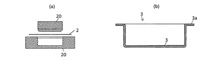
図2に示すように、第一打抜き工程10においては、例えば、金属板1(略四角形)が、上金型10aおよび下金型10bによって外形抜き加工され、ブランク2(略円形)が得られる。第一打抜き工程10は、予め、金属板1の中央部に穴抜き加工を施した後に上記の外形抜き加工を行うか、上記の外形抜き加工と同時に金属板1の中央部に穴抜き加工を施すか、上記の外形抜き加工を施した後に金属板1の中央部に穴抜き加工を施すことにより、中空ブランクを得る工程であってもよい。なお、この中空ブランクに形成される穴の直径は、後段の穴抜き加工によって形成される穴の大きさよりも小さいものである。このような中空ブランクを用いる場合には、穴が拡げられる際の加工負荷を軽減させ、加工時の肉薄減少を抑制できるとともに、最終製品の左右のフランジの質量バランスの調整が容易になる。
As shown in FIG. 2, in the
金属板としては、鉄合金板、アルミ合金板など様々な板材を用いることができるが、特に、鉄合金板を用いるのが好ましい。 As the metal plate, various plate materials such as an iron alloy plate and an aluminum alloy plate can be used. In particular, an iron alloy plate is preferably used.
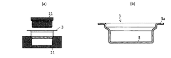
図3に示すように、絞り工程20においては、ブランク2が、上金型20aおよび下金型20bによって、絞り加工され、一端に予備フランジ3a、他端に底部3bを備える碗状素材3が得られる。この絞り工程20は、一回の工程により所定形状を有する碗状素材3を得ることとしてもよいし、二回以上の工程により所定形状の碗状素材3を得ることとしてもよい。すなわち、図4に示すように、絞り工程20においては、上記の碗状素材3を、上金型21aおよび下金型21bによって、絞り加工して、一端に予備フランジ3a、他端に底部3bを備え、さらに、最終製品のビードシート等に対応する予備的な形状を備える碗状素材3Aを得る工程であってもよい。
As shown in FIG. 3, in the
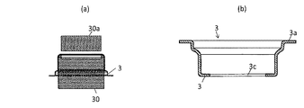
図5に示すように、第二打抜き工程30においては、碗状素材3Aが、上金型30aおよび下金型30bによって、穴抜き加工され、底部3bに穴3cを備える中空底部3Bが得られる。なお、この図では、予備的な形状を備える碗状素材3Aを加工する例を説明しているが、図3に示す碗状素材3に穴抜き加工を行ってもよい。第二打抜き加工工程30は、予め外形抜き加工により予備フランジ3aの形状を変更した後に穴抜き加工を施すか、穴抜き加工と同時に外形抜き加工により予備フランジ3aの形状を変更するか、穴抜き加工の後に外形抜き加工により予備フランジ3aの形状を変更する工程であってもよい。このように、第二打抜き工程において、外形抜き加工を行い、さらに前記予備フランジの形状を変更する構成であれば、材料の異方性によるフランジ幅のバラツキを最小限に抑える事ができるというメリットがある。
As shown in FIG. 5, in the
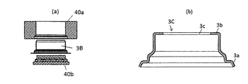
図6に示すように、フランジ成形工程40においては、碗状素材3bの予備フランジ3aが所定のフランジ形状に成形され、その後、図7に示すように、中空底部3bが碗状素材3Cの軸方向(図中矢印の方向)に立ち上げられ、中間成形体3Dが得られる。本実施形態においては、予備フランジ3aをフランジ形状に成形後に中空底部3bを立ち上げる場合を説明したが、予備フランジ3aのフランジ形状への成形および中空底部3b立ち上げを同時に行ってもよいし、また、中空底部3bを立ち上げた後に予備フランジ3aのフランジ形状への成形をしてもよい。
As shown in FIG. 6, in the flange forming step 40, the
図8に示すように、フレアリング工程60においては、中間成形体3Dの少なくとも一端を押し広げる工程である。なお、図8に示す例のように、碗状素材3のフランジ形状に3aであった端部(フランジ側端部)が、絞り加工によって、最終製品形状または最終製品に近い形状にまで加工されている中間成形体3Dを加工する場合には、碗状素材3の底部3bがあった端部(底部側端部)のみを押し広げればよい。一方、フランジ側端部が最終製品形状または最終製品に近い形状にまで加工されていない場合には、中間成形体3Dの両端(フランジ側端部および底部側端部の双方)を押し広げる必要がある。
As shown in FIG. 8, the flaring process 60 is a process of expanding at least one end of the intermediate molded
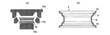
図9に示すように、本成形工程70においては、押し広げられた中間成形体3Eが、上金型70aおよび下金型70bによって、所定形状のフランジ4a、ビードシート4bおよびウエル4cを備えるホイールリム4が得られる。このとき、例えば、カム機構を用いて、上金型70aを下降させると、複数の外側金型70cが中間成形体3Eの外側から内方へ移動し、これにより中間成形体3Eを押圧して所定形状のホイールリムを得ることができる。なお、図示は省略するが、この工程の後に、さらに、ロール加工工程および/またはサイジング工程を実施して、フランジ4a、ビードシート4bおよびウエル4cなどの形状を整えればさらに好ましい。
As shown in FIG. 9, in the main molding step 70, the intermediate molded
2.ホイールリム
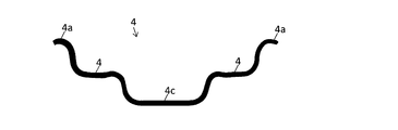
図10に示すように、本実施形態のホイールリム4は、両端にフランジ4a、その内側にビードシート4b、さらにその内側にウエル4cを備えるホイールリムであって、左右フランジに板厚差を設けることを特徴とする。このような板厚差を設ければ、ディスクの取り付け位置の調整、ブレーキ等の左右非対称な周辺部品との取付け位置の調整などにより、ホイールの左右の質量バランスをコントロールすることが可能となる。その結果、通常のホイールよりも優れた走行安定性を付与することができるからである。しかし、上記の板厚差が大きすぎると、加工割れが生じる。
2. Wheel Rim As shown in FIG. 10, the
よって、リム中心線における厚さをT0とするとき、一方のフランジの厚さTFAが、0.50T0以上1.00T0未満であり、他方のフランジの厚さTFBが、1.00T0を超え1.50T0以下であることが必要である。一方のフランジの厚さTFAの下限は、0.60T0であることが好ましく、上限は、0.90T0であることが好ましい。他方のフランジの厚さTFBの下限は、1.10T0であることが好ましく、上限は、1.40T0であることが好ましい。 Therefore, when the thickness at the rim center line is T 0 , the thickness T FA of one flange is 0.50 T 0 or more and less than 1.00 T 0 , and the thickness T FB of the other flange is 1. 00T is required to be more than 0 1.50T 0 below. The lower limit of the thickness T FA of one of the flanges is preferably 0.60 T 0, the upper limit is preferably 0.90T 0. The lower limit of the thickness T FB of the other flange is preferably 1.10 T 0 , and the upper limit is preferably 1.40 T 0 .
本実施形態に係るホイールリムは、特に、二輪車用ホイールリムとして有用である。二輪車においては、車体の質量バランスが左右均等ではないことが多く、そのような場合に本発明のホイールリムで車体全体の質量バランスを改善することが可能となるからである。また、本実施形態に係るホイールリムは、鉄合金板からなるものが好ましい。 The wheel rim according to the present embodiment is particularly useful as a wheel rim for a motorcycle. In a two-wheeled vehicle, the mass balance of the vehicle body is often not equal to the left and right, and in such a case, it is possible to improve the mass balance of the entire vehicle body with the wheel rim of the present invention. The wheel rim according to the present embodiment is preferably made of an iron alloy plate.
本発明の製造方法によれば、金属板(板状素材)から溶接を用いることなく、ホイールリムを製造する方法を提供することができる。また、本発明のホイールリムによれば、走行安定性において優れるホイールに用いることができる、左右フランジ部の板厚差があるホイールリムを提供することにある。 According to the manufacturing method of the present invention, it is possible to provide a method for manufacturing a wheel rim without using welding from a metal plate (plate-shaped material). Moreover, according to the wheel rim of this invention, it is providing the wheel rim with the plate | board thickness difference of a right-and-left flange part which can be used for the wheel excellent in driving | running | working stability.
1 金属板
2 ブランク
3 絞り工程後の碗状素材
3A 絞り工程後の碗状素材(予備的形状付き)
3B 第二打抜き工程後の中空碗状素材
3C フランジ成形工程後の中空碗状素材(フランジ成形)
3D 立ち上げ工程後の後の中間成形体(底部立ち上げ)
3E フレアリング工程後の中間成形体
3a 予備フランジ
3b 底部
3c 穴
4 ホイールリム
4a フランジ
4b ビードシート
4c ウエル
10 第一打抜き工程
10a 第一打抜き工程の上金型
10b 第一打抜き工程の下金型
20 絞り工程
20a 絞り工程の上金型
20b 絞り工程の下金型
21a 絞り工程の上金型(予備的形状付き)
21b 絞り工程の下金型(予備的形状付き)
30 第二打抜き工程
30a 第二打抜き工程の上金型
30b 第二打抜き工程の下金型
40 フランジ成形工程
40a フランジ成形工程の上金型
40b フランジ成形工程の下金型
50 立ち上げ工程
50a 立ち上げ工程の上金型
50b 立ち上げ工程の下金型
60 フレアリング工程
60a フレアリング工程の上金型
60b フレアリング工程の下金型
70 本成形工程
70a 本成形工程の上金型
70b 本成形工程の下金型
70c 本成形工程の外側金型
1
3B Hollow bowl-shaped material after
Intermediate molded body after 3D start-up process (bottom of bottom)
3E Intermediate molded
21b Lower die of drawing process (with preliminary shape)
30
Claims (6)
(1)外形抜き加工により、前記金属板からブランクを得る、第一打抜き工程と、
(2)前記ブランクから、一端に予備フランジ、他端に底部を備える碗状素材を得る、絞り工程と、
(3)穴抜き加工により、前記底部を中空底部とする、第二打抜き工程と、
(4)前記予備フランジをフランジ形状に成形する、フランジ成形工程と、
(5)前記中空底部を軸方向に立ち上げて中間成形体を得る、立ち上げ工程と、
(6)前記中間成形体の少なくとも一端を押し広げる、フレアリング工程と、
(7)両端が押し広げられた中間成形体から、ホイールリムを得る本成形工程とを備える、ホイールリムの製造方法。 A method of manufacturing a wheel rim from a metal plate,
(1) A first punching step of obtaining a blank from the metal plate by outer shape punching;
(2) A drawing step of obtaining a bowl-shaped material having a preliminary flange at one end and a bottom at the other end from the blank;
(3) a second punching step in which the bottom is a hollow bottom by punching;
(4) A flange forming step of forming the preliminary flange into a flange shape;
(5) A rising step in which the hollow bottom is raised in the axial direction to obtain an intermediate molded body;
(6) a flaring step of spreading at least one end of the intermediate molded body;
(7) A wheel rim manufacturing method comprising: a main molding step of obtaining a wheel rim from an intermediate molded body having both ends spread.
請求項1から3までのいずれかに記載のホイールリムの製造方法。 A roll processing step and / or a sizing step are further provided after the main forming step.
The method for manufacturing a wheel rim according to any one of claims 1 to 3.
リム中心線における厚さをT0とするとき、一方のフランジの厚さTFAが、0.50T0以上1.00T0未満であり、他方のフランジの厚さTFBが、1.00T0を超え1.50T0以下である、ホイールリム。 A wheel rim having flanges at both ends, a bead seat inside, and a well inside.
When the thickness at the rim center line is T 0 , the thickness T FA of one flange is 0.50 T 0 or more and less than 1.00 T 0 , and the thickness T FB of the other flange is 1.00 T 0. Wheel rim that is more than 1.50T 0 and less.
Priority Applications (1)
| Application Number | Priority Date | Filing Date | Title |
|---|---|---|---|
| JP2016038716A JP2017154152A (en) | 2016-03-01 | 2016-03-01 | Wheel rim and method for manufacturing same |
Applications Claiming Priority (1)
| Application Number | Priority Date | Filing Date | Title |
|---|---|---|---|
| JP2016038716A JP2017154152A (en) | 2016-03-01 | 2016-03-01 | Wheel rim and method for manufacturing same |
Publications (1)
| Publication Number | Publication Date |
|---|---|
| JP2017154152A true JP2017154152A (en) | 2017-09-07 |
Family
ID=59809013
Family Applications (1)
| Application Number | Title | Priority Date | Filing Date |
|---|---|---|---|
| JP2016038716A Pending JP2017154152A (en) | 2016-03-01 | 2016-03-01 | Wheel rim and method for manufacturing same |
Country Status (1)
| Country | Link |
|---|---|
| JP (1) | JP2017154152A (en) |
Cited By (1)
| Publication number | Priority date | Publication date | Assignee | Title |
|---|---|---|---|---|
| CN112404987A (en) * | 2020-10-26 | 2021-02-26 | 山东贞元汽车车轮有限公司 | Manufacturing system and process of automobile wheel steel ring |
-
2016
- 2016-03-01 JP JP2016038716A patent/JP2017154152A/en active Pending
Cited By (2)
| Publication number | Priority date | Publication date | Assignee | Title |
|---|---|---|---|---|
| CN112404987A (en) * | 2020-10-26 | 2021-02-26 | 山东贞元汽车车轮有限公司 | Manufacturing system and process of automobile wheel steel ring |
| CN112404987B (en) * | 2020-10-26 | 2021-06-08 | 山东贞元汽车车轮有限公司 | Manufacturing system and process of automobile wheel steel ring |
Similar Documents
| Publication | Publication Date | Title |
|---|---|---|
| JP6051052B2 (en) | Press part molding method, press part manufacturing method, and press part molding die | |
| US20150114067A1 (en) | Method for molding pressed component, method for manufacturing pressed component, and die for molding pressed component | |
| WO2014134767A1 (en) | Car steel ring spoke production and manufacture process and specific mould thereof | |
| JP5446787B2 (en) | Ring material manufacturing method | |
| JPWO2014109263A1 (en) | Press forming method | |
| JP2003275837A (en) | Method for manufacturing wheel rim of car | |
| JP2008290085A (en) | Method of forming flange part of hub hole of automotive wheel | |
| WO2014192833A1 (en) | Method for producing bottomed can | |
| JP2017154152A (en) | Wheel rim and method for manufacturing same | |
| KR101560686B1 (en) | Shock absorber cover manufacturing method | |
| JP5192845B2 (en) | Manufacturing method of wheel for automobile | |
| US9120143B2 (en) | Cut-off end surface improvement | |
| KR101855929B1 (en) | Manufacturing method for container shaped item such as oil pan | |
| JP2005313769A (en) | Wheel, and its manufacturing method | |
| JP6162540B2 (en) | Manufacturing method of wheel disc for vehicle | |
| JP5446785B2 (en) | Ring material manufacturing method | |
| JP5180742B2 (en) | Manufacturing method of wheel disc for automobile | |
| KR101661458B1 (en) | Method for manufacturing Double Forging Parts of inner race and boss | |
| WO2012026515A1 (en) | Method for forming undercut and method for manufacturing molded article having undercut | |
| JP5157957B2 (en) | Manufacturing method of shaft-shaped member with protrusion | |
| JP5322397B2 (en) | Method for manufacturing vehicle wheel and vehicle wheel | |
| JPH0790308B2 (en) | Pipe ring manufacturing method | |
| JP5622324B2 (en) | Method for forming metal cylinder | |
| JP2005034854A (en) | Method for forging taper bearing hot-forging blank | |
| JP3926667B2 (en) | Manufacturing method for hub inner ring |