JP2017149415A - Lighting device for motor vehicles - Google Patents
Lighting device for motor vehicles Download PDFInfo
- Publication number
- JP2017149415A JP2017149415A JP2017032375A JP2017032375A JP2017149415A JP 2017149415 A JP2017149415 A JP 2017149415A JP 2017032375 A JP2017032375 A JP 2017032375A JP 2017032375 A JP2017032375 A JP 2017032375A JP 2017149415 A JP2017149415 A JP 2017149415A
- Authority
- JP
- Japan
- Prior art keywords
- light
- lens
- optical element
- projection optical
- waveguide
- Prior art date
- Legal status (The legal status is an assumption and is not a legal conclusion. Google has not performed a legal analysis and makes no representation as to the accuracy of the status listed.)
- Ceased
Links
Images


Classifications
-
- F—MECHANICAL ENGINEERING; LIGHTING; HEATING; WEAPONS; BLASTING
- F21—LIGHTING
- F21V—FUNCTIONAL FEATURES OR DETAILS OF LIGHTING DEVICES OR SYSTEMS THEREOF; STRUCTURAL COMBINATIONS OF LIGHTING DEVICES WITH OTHER ARTICLES, NOT OTHERWISE PROVIDED FOR
- F21V5/00—Refractors for light sources
-
- B—PERFORMING OPERATIONS; TRANSPORTING
- B60—VEHICLES IN GENERAL
- B60Q—ARRANGEMENT OF SIGNALLING OR LIGHTING DEVICES, THE MOUNTING OR SUPPORTING THEREOF OR CIRCUITS THEREFOR, FOR VEHICLES IN GENERAL
- B60Q3/00—Arrangement of lighting devices for vehicle interiors; Lighting devices specially adapted for vehicle interiors
- B60Q3/60—Arrangement of lighting devices for vehicle interiors; Lighting devices specially adapted for vehicle interiors characterised by optical aspects
- B60Q3/62—Arrangement of lighting devices for vehicle interiors; Lighting devices specially adapted for vehicle interiors characterised by optical aspects using light guides
- B60Q3/64—Arrangement of lighting devices for vehicle interiors; Lighting devices specially adapted for vehicle interiors characterised by optical aspects using light guides for a single lighting device
-
- B—PERFORMING OPERATIONS; TRANSPORTING
- B60—VEHICLES IN GENERAL
- B60Q—ARRANGEMENT OF SIGNALLING OR LIGHTING DEVICES, THE MOUNTING OR SUPPORTING THEREOF OR CIRCUITS THEREFOR, FOR VEHICLES IN GENERAL
- B60Q3/00—Arrangement of lighting devices for vehicle interiors; Lighting devices specially adapted for vehicle interiors
- B60Q3/50—Mounting arrangements
- B60Q3/51—Mounting arrangements for mounting lighting devices onto vehicle interior, e.g. onto ceiling or floor
-
- B—PERFORMING OPERATIONS; TRANSPORTING
- B60—VEHICLES IN GENERAL
- B60Q—ARRANGEMENT OF SIGNALLING OR LIGHTING DEVICES, THE MOUNTING OR SUPPORTING THEREOF OR CIRCUITS THEREFOR, FOR VEHICLES IN GENERAL
- B60Q3/00—Arrangement of lighting devices for vehicle interiors; Lighting devices specially adapted for vehicle interiors
- B60Q3/60—Arrangement of lighting devices for vehicle interiors; Lighting devices specially adapted for vehicle interiors characterised by optical aspects
- B60Q3/62—Arrangement of lighting devices for vehicle interiors; Lighting devices specially adapted for vehicle interiors characterised by optical aspects using light guides
-
- B—PERFORMING OPERATIONS; TRANSPORTING
- B60—VEHICLES IN GENERAL
- B60Q—ARRANGEMENT OF SIGNALLING OR LIGHTING DEVICES, THE MOUNTING OR SUPPORTING THEREOF OR CIRCUITS THEREFOR, FOR VEHICLES IN GENERAL
- B60Q3/00—Arrangement of lighting devices for vehicle interiors; Lighting devices specially adapted for vehicle interiors
- B60Q3/70—Arrangement of lighting devices for vehicle interiors; Lighting devices specially adapted for vehicle interiors characterised by the purpose
- B60Q3/74—Arrangement of lighting devices for vehicle interiors; Lighting devices specially adapted for vehicle interiors characterised by the purpose for overall compartment lighting; for overall compartment lighting in combination with specific lighting, e.g. room lamps with reading lamps
-
- B—PERFORMING OPERATIONS; TRANSPORTING
- B60—VEHICLES IN GENERAL
- B60Q—ARRANGEMENT OF SIGNALLING OR LIGHTING DEVICES, THE MOUNTING OR SUPPORTING THEREOF OR CIRCUITS THEREFOR, FOR VEHICLES IN GENERAL
- B60Q3/00—Arrangement of lighting devices for vehicle interiors; Lighting devices specially adapted for vehicle interiors
- B60Q3/80—Circuits; Control arrangements
-
- F—MECHANICAL ENGINEERING; LIGHTING; HEATING; WEAPONS; BLASTING
- F21—LIGHTING
- F21V—FUNCTIONAL FEATURES OR DETAILS OF LIGHTING DEVICES OR SYSTEMS THEREOF; STRUCTURAL COMBINATIONS OF LIGHTING DEVICES WITH OTHER ARTICLES, NOT OTHERWISE PROVIDED FOR
- F21V19/00—Fastening of light sources or lamp holders
-
- F—MECHANICAL ENGINEERING; LIGHTING; HEATING; WEAPONS; BLASTING
- F21—LIGHTING
- F21V—FUNCTIONAL FEATURES OR DETAILS OF LIGHTING DEVICES OR SYSTEMS THEREOF; STRUCTURAL COMBINATIONS OF LIGHTING DEVICES WITH OTHER ARTICLES, NOT OTHERWISE PROVIDED FOR
- F21V5/00—Refractors for light sources
- F21V5/04—Refractors for light sources of lens shape
-
- F—MECHANICAL ENGINEERING; LIGHTING; HEATING; WEAPONS; BLASTING
- F21—LIGHTING
- F21V—FUNCTIONAL FEATURES OR DETAILS OF LIGHTING DEVICES OR SYSTEMS THEREOF; STRUCTURAL COMBINATIONS OF LIGHTING DEVICES WITH OTHER ARTICLES, NOT OTHERWISE PROVIDED FOR
- F21V7/00—Reflectors for light sources
-
- G—PHYSICS
- G02—OPTICS
- G02B—OPTICAL ELEMENTS, SYSTEMS OR APPARATUS
- G02B6/00—Light guides; Structural details of arrangements comprising light guides and other optical elements, e.g. couplings
- G02B6/0001—Light guides; Structural details of arrangements comprising light guides and other optical elements, e.g. couplings specially adapted for lighting devices or systems
- G02B6/0011—Light guides; Structural details of arrangements comprising light guides and other optical elements, e.g. couplings specially adapted for lighting devices or systems the light guides being planar or of plate-like form
- G02B6/0033—Means for improving the coupling-out of light from the light guide
- G02B6/005—Means for improving the coupling-out of light from the light guide provided by one optical element, or plurality thereof, placed on the light output side of the light guide
-
- B—PERFORMING OPERATIONS; TRANSPORTING
- B60—VEHICLES IN GENERAL
- B60Q—ARRANGEMENT OF SIGNALLING OR LIGHTING DEVICES, THE MOUNTING OR SUPPORTING THEREOF OR CIRCUITS THEREFOR, FOR VEHICLES IN GENERAL
- B60Q2400/00—Special features or arrangements of exterior signal lamps for vehicles
- B60Q2400/20—Multi-color single source or LED matrix, e.g. yellow blinker and red brake lamp generated by single lamp
-
- F—MECHANICAL ENGINEERING; LIGHTING; HEATING; WEAPONS; BLASTING
- F21—LIGHTING
- F21V—FUNCTIONAL FEATURES OR DETAILS OF LIGHTING DEVICES OR SYSTEMS THEREOF; STRUCTURAL COMBINATIONS OF LIGHTING DEVICES WITH OTHER ARTICLES, NOT OTHERWISE PROVIDED FOR
- F21V2200/00—Use of light guides, e.g. fibre optic devices, in lighting devices or systems
-
- F—MECHANICAL ENGINEERING; LIGHTING; HEATING; WEAPONS; BLASTING
- F21—LIGHTING
- F21W—INDEXING SCHEME ASSOCIATED WITH SUBCLASSES F21K, F21L, F21S and F21V, RELATING TO USES OR APPLICATIONS OF LIGHTING DEVICES OR SYSTEMS
- F21W2106/00—Interior vehicle lighting devices
-
- F—MECHANICAL ENGINEERING; LIGHTING; HEATING; WEAPONS; BLASTING
- F21—LIGHTING
- F21Y—INDEXING SCHEME ASSOCIATED WITH SUBCLASSES F21K, F21L, F21S and F21V, RELATING TO THE FORM OR THE KIND OF THE LIGHT SOURCES OR OF THE COLOUR OF THE LIGHT EMITTED
- F21Y2105/00—Planar light sources
- F21Y2105/10—Planar light sources comprising a two-dimensional array of point-like light-generating elements
-
- F—MECHANICAL ENGINEERING; LIGHTING; HEATING; WEAPONS; BLASTING
- F21—LIGHTING
- F21Y—INDEXING SCHEME ASSOCIATED WITH SUBCLASSES F21K, F21L, F21S and F21V, RELATING TO THE FORM OR THE KIND OF THE LIGHT SOURCES OR OF THE COLOUR OF THE LIGHT EMITTED
- F21Y2113/00—Combination of light sources
- F21Y2113/10—Combination of light sources of different colours
- F21Y2113/13—Combination of light sources of different colours comprising an assembly of point-like light sources
-
- F—MECHANICAL ENGINEERING; LIGHTING; HEATING; WEAPONS; BLASTING
- F21—LIGHTING
- F21Y—INDEXING SCHEME ASSOCIATED WITH SUBCLASSES F21K, F21L, F21S and F21V, RELATING TO THE FORM OR THE KIND OF THE LIGHT SOURCES OR OF THE COLOUR OF THE LIGHT EMITTED
- F21Y2115/00—Light-generating elements of semiconductor light sources
- F21Y2115/10—Light-emitting diodes [LED]
Abstract
Description
本発明は、特に照明システムに関する。 The present invention particularly relates to lighting systems.
一つの好適な用途は、自動車工業に関し、車両の装備のため、特に車両の客室内で(照明機能としても知られる)光ビームを放出し得るべき装置の製造のためのものである。照明という用語は、客室の一部分における合図や、あり得る装飾的な照明効果を含むものとして理解されたい。 One suitable application relates to the automotive industry, for the manufacture of equipment that should be able to emit a light beam (also known as a lighting function) in the vehicle cabin, in particular in the vehicle cabin. The term lighting should be understood as including cues in a part of the cabin and possible decorative lighting effects.
車両の客室には従来、複数の照明装置が設けられている。例えば、オーバーヘッドライト(頭上灯)やリーディングライト(読書灯)がしばしば存在している。オーバーヘッドライトの場合には、概して、運転席側の方へ光を向ける照明システムと、別個に助手席側の方へ光を向ける照明システムとを作動させることの可能なのが一般的である。これは、必要な照明形式があるのと同数のシステムを要求する。 Conventionally, a plurality of lighting devices are provided in a passenger compartment of a vehicle. For example, there are often overhead lights (overhead lights) and reading lights (reading lights). In the case of overhead lights, it is generally possible to operate a lighting system that directs light towards the driver's side and a lighting system that directs light towards the passenger side separately. This requires as many systems as there are required lighting formats.
本発明は、自動車両の客室における室内照明ビームの精細度を向上させようとするものである。 The present invention seeks to improve the definition of an interior illumination beam in a cabin of a motor vehicle.
本発明は、自動車両の客室用の照明システムに関するものである。そのシステムは、光ビーム成形装置と、光ビームを出力ビームへと変換するように構成された投射光学素子とを含んでいる。ビーム成形装置は、複数のサブビームで形成されるピクセル化された光ビームを放出するように構成される有利さを有している。 The present invention relates to a lighting system for a passenger room of a motor vehicle. The system includes a light beam shaping device and projection optics configured to convert the light beam into an output beam. The beam shaping device has the advantage of being configured to emit a pixelated light beam formed by a plurality of sub-beams.
このタイプの照明システムは、作り出されるべき照明形態を変更することを可能とする。それは、ビームの形状がピクセル化されることで、制御手段によってビームを容易に変更することができるからである。これらの変更は、投射光学素子の変更を必要とはしない。例えば、本発明による単一のシステムは、運転者の方へ光を向ける機能、助手席の乗客の方へ光を向ける機能、後席の乗客の方へ光を向ける機能、および全体照明の機能を持ったオーバーヘッドライトとして役立つことができる。これらの異なる機能同士の間では、ビームの各ピクセルがどのように制御されるかということだけが変更される、という有利さがある。この原理は、窓の上縁付近に位置するコンフォートハンドル(アシストグリップ)の高さの所や、座席の基部における足の高さの所や、ルーフピラーの高さの所にも、同様に申し分なく適用され得る。 This type of lighting system makes it possible to change the lighting form to be created. This is because the beam shape can be easily changed by the control means by making the beam shape into a pixel. These changes do not require changes to the projection optics. For example, a single system according to the present invention has the function of directing light toward the driver, the function of directing light toward the passenger in the passenger seat, the function of directing light toward the passenger in the rear seat, and the function of overall illumination Can serve as an overhead light. The advantage is that between these different functions, only the way each pixel of the beam is controlled is changed. This principle is equally perfect at the height of the comfort handle (assist grip) located near the upper edge of the window, the height of the foot at the base of the seat, and the height of the roof pillar. Can be applied.
従って、ピクセル化されたビームの使用が複雑なものであって客室を照明するには不適当であると演繹的に考えられてきたかもしれないのに対して、本発明は、照明素子類の機能を増大させながら同時にそれらの素子類を限定することによって、客室の設備を合理化することを可能としている。 Thus, while the use of pixelated beams may be complex and may have been considered a priori as unsuitable for illuminating a cabin, the present invention It is possible to rationalize the facilities of the guest room by limiting those elements while increasing the function.
本システムは、作動されるサブビーム同士の異なる組合せにそれぞれ対応する複数のビーム形態から、光ビームが選択されるように構成されるのが有利である。各サブビームの作動は、それらを点灯したり消灯したりすることであっても、また光度その他の光のパラメータを変化させることであってもよい。サブビーム同士の組合せのそれぞれが、必要な照明機能に対応し得るのである。 The system is advantageously configured such that the light beam is selected from a plurality of beam configurations, each corresponding to a different combination of activated sub-beams. The operation of each sub-beam may be to turn them on and off, or to change the light intensity and other light parameters. Each combination of sub-beams can correspond to the required illumination function.
一つの可能性によれば、ビーム成形装置は、ピクセル化された光ビームに関与し得るサブビームをそれぞれが放出することのできる複数の光源を含む。 According to one possibility, the beam shaping device includes a plurality of light sources each capable of emitting sub-beams that may be involved in the pixelated light beam.
従って、各サブビームは、それが点灯したり消灯したりするように、および/または、その光度が制御されるように、制御することができる。例えば、光源のうち少なくとも1つは、少なくとも2つの基本発光体を含んでいる。その結果、対応するサブビームを変更するように各発光体を個々に制御することが可能となる。 Thus, each sub-beam can be controlled so that it is turned on and off and / or its intensity is controlled. For example, at least one of the light sources includes at least two basic light emitters. As a result, each light emitter can be individually controlled to change the corresponding sub-beam.
一つの可能性によれば、少なくとも2つの発光体のうち少なくとも2つ同士が、互いに異なる色の光ビームを放出するように構成される。関係する光源からのサブビームに対するそれらの発光体の寄与は、従って補足的なものとなり得るが、これにより、各発光体、ないしは一部の発光体を互いに異なるように制御することによって、実行可能な(例えば色の)変化を生じさせることができる。随意に、少なくとも2つの基本発光体を含む少なくとも1つの光源は、少なくとも2個のチップ、例えば少なくとも10個のチップを伴った発光ダイオードである。発光ダイオードのチップとは、電気的に励起されたときに光子を放出することのできる半導体素子を意味する。そのチップはまた、それ自体によって、或いは当該チップによって放出された光の波長を変換する発光団と共同してのいずれかで、発光体を形成する。これは例えば、2×30チップのマトリックス、より一般的には、複数の行および列で構成されたマトリックスであって、各行が少なくとも5個の基本発光体(即ち、選択的に作動可能な最小の照明単位)、好ましくは少なくとも10個の基本発光体を含んでいるものを意味している。 According to one possibility, at least two of the at least two light emitters are configured to emit light beams of different colors. The contribution of those illuminants to the sub-beams from the relevant light sources can therefore be complementary, but this can be done by controlling each illuminant or some illuminants differently from each other. Changes (e.g. color) can be produced. Optionally, the at least one light source comprising at least two basic light emitters is a light emitting diode with at least two chips, for example at least ten chips. A light emitting diode chip refers to a semiconductor device that can emit photons when electrically excited. The chip also forms a light emitter, either by itself or in conjunction with a luminophore that converts the wavelength of the light emitted by the chip. This may be, for example, a 2 × 30 chip matrix, more generally a matrix of rows and columns, each row having at least 5 elementary light emitters (ie, the smallest selectively operable). Means that it contains at least 10 basic light emitters.
いずれにしても、当該システムは、2つの発光体、特に互いに異なる色を発する発光体を備えた光源を有していてよく、当該光源が、行と列のマトリックス、例えば2個のチップを伴った(バイチップLEDとも称される)発光ダイオードの5行6列のマトリックスに従って基板上に配置されていてもよい。或いは、当該システムは、同じ光源ハウジングの内部に行と列に従って(有利には、互いに異なる色を発する発光体の対ごとに)配置される多数の発光体を備えた、唯一の光源を有していてもよい。 In any case, the system may have a light source with two light emitters, in particular light emitters that emit different colors, and the light source involves a matrix of rows and columns, for example two chips. Alternatively, they may be arranged on the substrate according to a 5 × 6 matrix of light emitting diodes (also referred to as bi-chip LEDs). Alternatively, the system has a single light source with multiple light emitters arranged in rows and columns (advantageously for each pair of light emitters emitting different colors) within the same light source housing. It may be.
本発明はまた、本発明による照明システムを少なくとも1つ装備した車両にも関する。 The invention also relates to a vehicle equipped with at least one lighting system according to the invention.
その車両は、客室の天井の縁(例えばドア付近)におけるコンフォートハンドルの高さの所にある、この種の照明システム、および/または客室のオーバーヘッド(頭上)照明システムを含んでいてもよい。 The vehicle may include such a lighting system at the height of the comfort handle at the edge of the cabin ceiling (eg, near the door) and / or a cabin overhead (overhead) lighting system.
本発明はまた、車両の客室を照明する方法にも関する。 The invention also relates to a method for illuminating a vehicle cabin.
その方法は従って、同じシステムで、特に唯一の光学的な部分でもって、諸要件の関数として照明を適合させることを可能とする。制御電子機器によって、本発明により許される自由度の全てを完全に利用することを可能とすることが好ましい。 The method thus makes it possible to adapt the illumination as a function of the requirements in the same system, in particular with only one optical part. It is preferred that the control electronics allow full use of all the degrees of freedom permitted by the present invention.
本発明のその他の特徴や利点は、本発明の例示的実施形態を示す説明および図面に照らして、より良好に理解されることとなる。 Other features and advantages of the present invention will be better understood in the light of the description and drawings that illustrate exemplary embodiments of the invention.
以下の説明において、本発明の異なる実施形態同士に渡って、同じ参照符号は同様の概念を表すのに用いられることとなる。 In the following description, the same reference numerals will be used to represent similar concepts across different embodiments of the present invention.
特にそれとは反対に指示されない限り、所与の実施形態について詳細に説明される技術的な諸特徴は、非限定的な例として表される他の実施形態の文脈において説明される技術的な諸特徴と組み合わされてもよい。 Unless otherwise indicated, technical features described in detail for a given embodiment are technical features described in the context of other embodiments that are presented as non-limiting examples. May be combined with features.
ピクセル化されたビームという用語およびその同義語は、光ビームを放出する装置について、当該光ビームが複数のサブビームで形成され、各サブビームが他のサブビームから独立して制御可能である、ということを表す。それぞれの独立して(個々に)制御可能なサブビームが、ピクセル化された光線を形成する。 The term pixelated beam and its synonyms refer to a device that emits a light beam, where the light beam is formed of multiple sub-beams, each sub-beam being controllable independently of the other sub-beams. Represent. Each independently (individually) controllable sub-beam forms a pixelated ray.
本発明の実施形態を(特に図面を参照して)詳細に説明する前に、本発明を(個別に、或いはあらゆる組合せにおいて)特徴付け得る可能な選択肢を、以下に簡潔に紹介する。
− ビーム成形装置は、ピクセル化された光ビームに関与し得るサブビームをそれぞれが放出することのできる複数の光源を含んでいる。
− 光源のうち少なくとも1つは、少なくとも2つの基本発光体を含んでいる。
− 少なくとも2つの発光体のうち少なくとも2つ同士が、互いに異なる色の光ビームを放出するように構成されている。
− 少なくとも2つの基本発光体を含む少なくとも1つの光源は、少なくとも2個のチップを伴った発光ダイオードである。
− ビーム成形装置は、各光源と関連付けられた導波路を含み、各導波路は、関連付けられた光源によって放出される光のための入光屈折面と、投射光学素子の方へ伝達される光のための出光屈折面とを含んでいる。
− 導波路は、入光屈折面から出光屈折面に向かって寸法の増大する多角形断面を有している。
− 投射光学素子はレンズを含み、そのレンズの入光屈折面が、導波路の出光屈折面によって伝達される光の少なくとも一部を受けるように構成されている。
− 導波路の出光屈折面は、レンズの入光屈折面と接している。
− 投射光学素子は、レンズから出る光の経路上に付加レンズを含んでいる。
− 付加レンズは集束レンズである。
− 投射光学素子は、出力ビームの出光反射器を含んでいる。
− 反射器は平面型である。
− 反射器は集束型であり、
− 当該システムは、各サブビームを個々に制御するための手段を含んでいる。
Before describing embodiments of the invention in detail (especially with reference to the drawings), the following briefly introduces possible options that can characterize the invention (individually or in any combination).
The beam shaping device comprises a plurality of light sources each capable of emitting sub-beams that may be involved in the pixelated light beam;
At least one of the light sources comprises at least two basic light emitters.
-At least two of the at least two light emitters are configured to emit light beams of different colors.
The at least one light source comprising at least two basic light emitters is a light emitting diode with at least two chips.
The beam shaping device includes a waveguide associated with each light source, each waveguide being a light entrance refracting surface for light emitted by the associated light source and light transmitted towards the projection optical element; And a light output refracting surface.
The waveguide has a polygonal cross section with increasing dimensions from the light entrance refracting surface to the light exiting refracting surface;
The projection optical element comprises a lens, the light entrance refracting surface of the lens being configured to receive at least part of the light transmitted by the light exiting refracting surface of the waveguide;
The light exit refracting surface of the waveguide is in contact with the light entrance refracting surface of the lens;
The projection optical element includes an additional lens in the path of light exiting the lens.
-The additional lens is a focusing lens.
The projection optical element comprises an output beam output reflector.
-The reflector is planar.
The reflector is a focusing type;
The system includes means for controlling each sub-beam individually;
ここで、以下に述べる各図によって非限定的な例として図解される、本発明の特有の一実施形態を説明することとする。 A specific embodiment of the present invention will now be described which is illustrated as a non-limiting example by the figures described below.
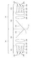
図1は、本発明のシステムの一実施形態を図式的に示している。そこにあるシステムは、当該システムによって作り出される光線の経路に沿った上流側区域から下流側区域に向かって、ビーム成形装置1と投射光学素子2とを含んでいる。ビーム成形装置1はそれ自体の中に、光線を発生させる部分と、適切なピクセル化された光線を投射光学素子2へ送り出すことを可能とする光学的部分とを含んでいる。その光線を発生させる部分は、複数の光源4を含んでいる。
FIG. 1 schematically illustrates one embodiment of the system of the present invention. The system there includes a beam shaping device 1 and a projection
一般的には、本発明は発光ダイオード(LED)タイプの光源を用いてよい。特に、これらのLEDは、実施すべき照明機能に従って、光度を調節可能であることが有利である光を放出するように適合された、少なくとも1つのチップを含んでいてよい。それらのチップは、LEDの平均発光方向に対して垂直に並置されていてよい。以降でより詳細に説明するように、複数の光源が存在していてもよい。さらに、光源という用語は、本発明のシステムの出光部において、少なくとも1つの必要な機能に関与する少なくとも1つの出光サブビームの発生に繋がる光束を作り出すことのできる、少なくとも1つのLEDなどの基本発光体の組合せを表すものと理解されたい。本発明の文脈内において他のタイプの光源も考えられ得る。LEDという用語は、OLED(有機発光ダイオード)類をも包含するものである。 In general, the present invention may use a light emitting diode (LED) type light source. In particular, these LEDs may comprise at least one chip adapted to emit light that is advantageously adjustable in light intensity according to the illumination function to be performed. These chips may be juxtaposed perpendicular to the average emission direction of the LEDs. As will be described in more detail below, a plurality of light sources may be present. Furthermore, the term light source refers to a basic light emitter, such as at least one LED, capable of producing a light flux leading to the generation of at least one outgoing sub-beam involved in at least one required function in the outgoing part of the system of the invention. It should be understood that it represents a combination of Other types of light sources are also conceivable within the context of the present invention. The term LED also encompasses OLEDs (organic light emitting diodes).
図1の場合、各光源4は、光の発生における優れた順応性を可能とするように、2つの基本発光体5(即ち、チップ)を含んでいる。実際に、光源の一部ないし全部が、発光体5を個々に制御することによって、照明パラメータ(例えば、各発光体5の光度や光源4の色など)が可変な状態で、制御可能な個々のサブビームを(かくして、全体的なビームのうちの1つのピクセルを)作り出し得る有利さがある。発光体5同士が互いに異なる色を発することが好ましい。2色同士の間での連続的な変化を可能とするために、例えば光導波路に面した光源4同士が互いに異なる色(例えば白色と琥珀色)となっている。 In the case of FIG. 1, each light source 4 includes two basic light emitters 5 (i.e., chips) to allow excellent flexibility in light generation. Actually, some or all of the light sources can be controlled individually by controlling the light emitters 5 so that the illumination parameters (for example, the luminous intensity of each light emitter 5 and the color of the light source 4) are variable. Of sub-beams (and thus one pixel of the overall beam) can be created. It is preferable that the light emitters 5 emit different colors. In order to enable continuous change between the two colors, for example, the light sources 4 facing the optical waveguide have different colors (for example, white and amber).
従って、各光源4および各発光体の制御は、それを点灯したり消灯したりすることだけでなく、放出される光のパラメータを変化させることをも意味するものと理解されたい。 Thus, the control of each light source 4 and each light emitter should be understood to mean not only turning it on and off, but also changing the parameters of the emitted light.
図1は、各光源が(図1では垂直な)一平面内に位置しているのが好ましいことを示している。各光源4は、そのような平面内でアレイに編成されていてよい。各光源4は例えば、主方向に整列されるか、或いは2方向に(例えば、行と列で構成されたアレイに)編成される。各光源4の如何なる他の設置形態も可能である。それらの光源同士が、設置平面内で規則的に等距離で間隔を置かれているのが好ましい。その平面は典型的には、例えばプリント回路基板(PCB)などのLED支持基板の表面である。この種の基板15は、図4に見ることができる。その基板は、各光源4へ選択的に電力を供給することによって、少なくとも部分的に、それらの光源を制御するのに役立ち得る。この基板15上で、或いは別個に、各光源が(例えば、プロセッサと、1つないし複数の異なる照明機能をプログラムするための手段とによって)制御され得る。この可能性は、制御基板16を伴った図4の例に示されている。一つの可能性によれば、制御基板16は、任意の手段(押ボタンの押し込み、ダッシュボードから到来する指令、オンボードコンピュータ・インターフェイスによって発せられる信号、(例えばドア開放の)センサなど)から、照明機能を作動させる命令を受ける。基板16は、この命令を、次のことによって処理する。即ち、対応する各光源の制御構成を確認して、各光源の電力供給構成の指示を基板15へ送信すること、特に各光源4の各発光体5に対して電力供給設定値を適用することによってである。
FIG. 1 shows that each light source is preferably located in a plane (perpendicular in FIG. 1). Each light source 4 may be organized in an array in such a plane. Each light source 4 is, for example, aligned in the main direction or organized in two directions (eg in an array composed of rows and columns). Any other form of installation of each light source 4 is possible. The light sources are preferably regularly spaced at equal distances in the installation plane. The plane is typically the surface of an LED support substrate such as a printed circuit board (PCB). Such a
各光源4によって放出された光線を光学的に処理することが有利である。この目的のために、装置1は光学的部分を含んでいてよく、その光学的部分には複数の導波路6(有利には、各光源4につき1つの導波路6)が設けられていることが好ましい。図1の場合には、各導波路6が、当該導波路の基端部から当該導波路の先端部へ向かって広がった外側エンベロープを有している。これは、円錐形その他のエンベロープであってよい。導波路は例えば、ポリカーボネート、ポリメチルメタクリレート(PMMA)、またはシリコーンで作られていてよい。導波路の断面は、多角形であることが好ましいが、円形であってもよい。基端部の所は入光屈折面61となっており、その屈折面61を通じて、光源4によって放出された光線が導波路へ進入する。これは、導波路のエンベロープを横切っている、その導波路の面であってよい。導波路6は、その内部で光線を、自らの先端部における出光屈折面62へと、内部反射によって伝播させるように構成されている。この屈折面は、導波路のエンベロープを横切っている、その導波路の面であってよい。
It is advantageous to optically process the light emitted by each light source 4. For this purpose, the device 1 may include an optical part, which is provided with a plurality of waveguides 6 (preferably one
装置を出て行く光線を受ける投射光学素子2は、用途によって変化することのできる構成を有していてよい。それは、光線の偏向の機能、および/または、集束ないし発散および/または拡散および/または回折および/または(例えば、着色面その他による)濾光の機能を含んでいてよい。
The projection
投射光学素子2は、それぞれが1つないし複数の光学的機能を与えるように適合された複数の構成要素を含んでいてよい。図示しない状況において、投射光学素子2は、少なくとも部分的に透明ないし半透明なキャップ(これは、光学的に中性の(波長選択性の無い)ものとすることができる)を含んでいるか、或いは、そのようなキャップに本質があってもよい。
The projection
図1にあるように、その光学素子は、(少なくとも)1つのレンズ7を更に含んでいてもよい。そのレンズ7は、全ての作動光源によって作り出される光線同士を結び付けるように、全ての導波路の出光屈折面62同士に共通のものであることが好ましい。図1の場合には、コンパクトな装置1を作り出すように、レンズの入光屈折面が出光屈折面62と接している。レンズ7は、導波路6と一体構成になっていてもよい。図1において、各光線はレンズ7の出光屈折面を通じて装置1から出て行く。レンズ7は、集束レンズであることが好ましく、例えば平凸形状を有していてよい。その平坦な屈折面は、各導波路の(これらも平坦であり得る)出光屈折面62との良好な協働を可能とすることができる。レンズ7内での光線の経路11aと、その光線の退出11bとが、図式的に示されている。
As shown in FIG. 1, the optical element may further comprise (at least) one
一選択肢によれば、装置1の光軸は、システム全体を出る光線に必要とされるものではない。この目的のために投射光学素子2は、図1の場合のように偏向機能をもたらし得る。実際に、装置1の光軸の方向へ比較的長く伸びた全体的な外形でシステムを製造し、そのシステムを客室の壁と平行に配置して、所要の出力方向へ各光線を逸らすことが可能である。それゆえ図1は、各光線が出て行く前にそれらの光線を偏向させるのに役立つ反射器3を示している。従って、光線11dの方向は、反射器3の受けた光線11cに対して偏向させられている。反射器3は特に、平面鏡や、凹面ないし凸面鏡であってよい。本発明を限定することなく、偏向は90°±30°であってよい。
According to one option, the optical axis of the device 1 is not required for rays exiting the entire system. For this purpose, the projection
図1の例によれば、投射光学素子はまた、ビームを集中させる役目をするのが好ましい付加レンズ8を含んでいる。そのレンズは、例えば両凸レンズである。
According to the example of FIG. 1, the projection optical element also includes an
図1において、そのレンズは、レンズ7と反射器3との間に配置され、レンズ7の光軸に沿った向きにされている。
In FIG. 1, the lens is disposed between the
提案されたシステムは、コンパクトで容易に設置することができる。図2および図3は、ドアの上部外周に(例えば、コンフォートハンドル9の高さの所に)備え付けられるように客室内に固定されたシステムによって、このことを例示している。本発明のシステムは、そのハンドル上にあったり、そのハンドルに統合されていたりしてもよい。照らすことのできる区域10の一例が、図式的に示されている。本発明のおかげで、この区域が、例えば3つの区域へと分割され得る。それらの区域は、それぞれが予め定められた1つの照明機能に対応していて、それぞれが光源4同士の異なる作動、従って当該機能の照明ビームを構成するための様々なサブビーム同士の異なる作動を含意している。照らされる容積は、必ずしも連続してはおらず、互いに分離した複数の空間の部分を含んでいてもよい。時間の経過によって変化し得るビーム、そして例えば、定期的に(光度および/または照明区域が周期的に変化)、および/または、増大および/または減少する光度の段階を伴って変化し得るビームを発生させるように構成された照明機能を何ら除外するものではない。
The proposed system is compact and easy to install. FIGS. 2 and 3 illustrate this by a system secured in the cabin to be mounted on the upper perimeter of the door (eg at the height of the comfort handle 9). The system of the present invention may be on or integrated with the handle. An example of an
これの具体例が、図4に示されている。そこではモジュール12が、上述した構成要素、即ち装置1、(ここではレンズ7,8および反射器3を伴った)投射光学素子を、(特にLEDの形態の)各光源を支持する基板15、および制御基板16と共に含んでいる。これらの構成要素を、装置1の光軸に対応したシステムの縦方向に順次、案内面が受け入れることができる。この例において各光線は、区域17を通じてシステムの縦軸線に対して90°で出て行く。区域17は例えば、モジュール12における窓である。その窓には、それ自体に保護ガラス14が備え付けられていてよい。最後に、各構成要素が取り付けられてしまったならば、キャップ13がモジュール12を閉じてよい。案内面が各構成要素の縦方向の並進における移動を防止し、キャップ13がモジュールの対向した底部と協働して如何なる残りの横方向移動をも防止する。反射器3の外周部が枠に取り付けられてもよい。支持リブ18が、その後面を介して反射器3を固定するように、キャップの内面から突き出ていることが好ましい。
A specific example of this is shown in FIG. There, the
図5は、本発明のシステムの一代替実施形態を図式的に示している。この実施形態において、システムは2つの分岐部B1,B2を集めている。 FIG. 5 schematically illustrates an alternative embodiment of the system of the present invention. In this embodiment, the system collects two branches B1, B2.
各分岐部は、図1について上述したような諸要素によって構成されている。同一要素の参照符号は、分岐部B1の各要素について100だけ増やされ、分岐部B2の各要素について200だけ増やされている。 Each branch is constituted by various elements as described above with reference to FIG. The reference number of the same element is increased by 100 for each element of the branch part B1, and is increased by 200 for each element of the branch part B2.
分岐部B1およびB2は、破線で示された正中面Pの両側に配置されている。 The branch portions B1 and B2 are arranged on both sides of the median plane P indicated by a broken line.
分岐部B1およびB2は、正中面Pに対して鏡像対称に配置されていることが有利である。 The branches B1 and B2 are advantageously arranged mirror-image-symmetrically with respect to the median plane P.
図5に示す代替案においては、反射器103および203同士が連結されている。それらの反射器は、V字形のプロファイルを有した組立体を形成している。2つの反射器同士の接合縁Jは、P平面内に位置している。或いは、分岐部同士が互いに対して非対称である場合や、反射器103,203が湾曲している場合には、接合縁が平面Pの外部に位置する可能性がある。
In the alternative shown in FIG. 5, the
或いは、反射器103および203は、互いに分離して配置された2つの部品である。
Alternatively, the
分岐部B1およびB2を構成する各要素は、それらの要素を回転させるだけで分岐部B1およびB2の両者で当該要素を用いることができるように対称軸線を有しているのが有利である。従って、製造せねばならぬ要素の種類数を減らして、システム全体を経済的に生産することが可能である。 Each element constituting the branch parts B1 and B2 advantageously has an axis of symmetry so that the element can be used in both the branch parts B1 and B2 simply by rotating those elements. Therefore, it is possible to economically produce the entire system by reducing the number of types of elements that must be manufactured.
或いは、各要素を、一方の分岐部ともう一方の分岐部とで異ならせることができる。例として、光源104の数や関連した導波路の数が、光源204の数や関連した導波路の数と異なっていてもよい。同様に、投射光学素子102,202を構成する光学部品類の性質や形態が、一方の分岐部と他方の分岐部とで変わっていてもよい。
Alternatively, each element can be different between one branch and the other branch. As an example, the number of
この代替実施形態は、図4で提示されたように、客室内に取り付けることのできるモジュールに統合することができる。その場合、反射器103および203は、2つの分岐部B1およびB2によって共有される窓17の前方に定置される。或いは、ハウジング12は、各分岐部B1,B2につき1つずつの、2つの窓を集めることができる。
This alternative embodiment can be integrated into a module that can be installed in the cabin as presented in FIG. In that case, the
この代替実施形態は、図1で説明した実施形態に比べて、各光源の平面に平行な方向においてシステムのフットプリント(設置面積)を減少させる利点を有している。それにより、そのようなシステムの、客室内への、特に小さな高さおよび/または奥行きしか利用できない場所への、最も容易な統合が可能となる。 This alternative embodiment has the advantage of reducing the footprint of the system in the direction parallel to the plane of each light source compared to the embodiment described in FIG. This allows the easiest integration of such a system into the cabin, especially where only a small height and / or depth is available.
各光源を遠く離れた幾つかの支持体上に分散させることによって与えられる、もう一つの利点は、当該光源の加熱や熱の管理を制限するということである。 Another advantage afforded by distributing each light source on several distant supports is that it limits the heating and heat management of the light source.
もう一つの利点は、各光源の駆動をより容易にすることである。実際に、多数の光源を駆動するための電子基板よりも、減らされた数の光源を駆動するための電子基板を提供する方が容易である。従って、各光源を遠く離れた幾つかの支持体上に分散させることによって、所与の1つの電子基板によって駆動されるべき光源の数が、図1で説明した実施形態に比べて減少する。そうして、システムの全体的な電子的駆動が簡素化される。 Another advantage is that each light source can be driven more easily. Indeed, it is easier to provide an electronic substrate for driving a reduced number of light sources than an electronic substrate for driving multiple light sources. Thus, by distributing each light source on several remotely spaced supports, the number of light sources to be driven by a given electronic substrate is reduced compared to the embodiment described in FIG. Thus, the overall electronic drive of the system is simplified.
本発明は、説明した諸実施形態に限定されるものではなく、その趣旨と一致する如何なる実施形態をも包含するものである。 The present invention is not limited to the described embodiments, but includes any embodiments that are consistent with the spirit thereof.
Claims (15)
Priority Applications (1)
| Application Number | Priority Date | Filing Date | Title |
|---|---|---|---|
| JP2022016642A JP2022063878A (en) | 2016-02-24 | 2022-02-04 | Lighting device for motor vehicles |
Applications Claiming Priority (2)
| Application Number | Priority Date | Filing Date | Title |
|---|---|---|---|
| FR1651520A FR3048068B1 (en) | 2016-02-24 | 2016-02-24 | LIGHTING SYSTEM FOR MOTOR VEHICLE CABIN |
| FR1651520 | 2016-02-24 |
Related Child Applications (1)
| Application Number | Title | Priority Date | Filing Date |
|---|---|---|---|
| JP2022016642A Division JP2022063878A (en) | 2016-02-24 | 2022-02-04 | Lighting device for motor vehicles |
Publications (1)
| Publication Number | Publication Date |
|---|---|
| JP2017149415A true JP2017149415A (en) | 2017-08-31 |
Family
ID=55808681
Family Applications (2)
| Application Number | Title | Priority Date | Filing Date |
|---|---|---|---|
| JP2017032375A Ceased JP2017149415A (en) | 2016-02-24 | 2017-02-23 | Lighting device for motor vehicles |
| JP2022016642A Pending JP2022063878A (en) | 2016-02-24 | 2022-02-04 | Lighting device for motor vehicles |
Family Applications After (1)
| Application Number | Title | Priority Date | Filing Date |
|---|---|---|---|
| JP2022016642A Pending JP2022063878A (en) | 2016-02-24 | 2022-02-04 | Lighting device for motor vehicles |
Country Status (5)
| Country | Link |
|---|---|
| US (1) | US10569705B2 (en) |
| EP (1) | EP3210829B1 (en) |
| JP (2) | JP2017149415A (en) |
| CN (1) | CN107120591B (en) |
| FR (1) | FR3048068B1 (en) |
Families Citing this family (12)
| Publication number | Priority date | Publication date | Assignee | Title |
|---|---|---|---|---|
| FR3062096B1 (en) * | 2017-01-26 | 2022-04-15 | Valeo Vision | DEVICE FOR CONTROLLING A MATRIX OF LIGHT SOURCES FOR THE INTERIOR LIGHTING OF THE CABIN OF A MOTOR VEHICLE |
| FR3079473B1 (en) * | 2018-03-30 | 2020-10-02 | Valeo Vision | INTERIOR LIGHTING SYSTEM FOR MOTOR VEHICLES |
| FR3079474B1 (en) * | 2018-03-30 | 2020-10-02 | Valeo Vision | OPTICAL SYSTEM FOR MOTOR VEHICLES |
| FR3083295B1 (en) * | 2018-06-29 | 2022-10-14 | Valeo Vision | LIGHT SOURCE ALLOWING THE EMISSION OF DISTINCT WHITE LIGHTS |
| FR3085640B1 (en) * | 2018-09-12 | 2022-08-05 | Valeo Vision | COMPACT OPTICAL SYSTEM FOR MOTOR VEHICLE CABIN |
| FR3090077B1 (en) | 2018-12-17 | 2021-05-07 | Valeo Vision | Interior lighting device of a motor vehicle capable of projecting a pixelated light beam |
| FR3090523B1 (en) * | 2018-12-19 | 2021-01-01 | Valeo Comfort & Driving Assistance | Lighting device for vehicle ceiling light |
| EP3838673B1 (en) * | 2019-12-18 | 2023-08-02 | Volvo Car Corporation | An improved lighting system for providing transformable light |
| DE102020000354A1 (en) | 2020-01-22 | 2021-07-22 | Daimler Ag | Interior lighting for a vehicle and method for suppressing kinetosis |
| CN112984454A (en) * | 2020-04-30 | 2021-06-18 | 华域视觉科技(上海)有限公司 | Photoconductor for vehicle lamp, high beam illumination module and vehicle lamp |
| EP4023499B1 (en) * | 2020-12-29 | 2023-08-30 | Grupo Antolin-Ingenieria, S.A. | Vehicle headliner with an integrated lighting module having a spotlighting function and manufacturing process thereof |
| FR3131500A1 (en) * | 2021-12-26 | 2023-06-30 | Valeo Vision | Light source with several types of light-emitting diodes |
Citations (4)
| Publication number | Priority date | Publication date | Assignee | Title |
|---|---|---|---|---|
| US20030174499A1 (en) * | 2002-03-14 | 2003-09-18 | Bohlander Richard A. | LED light source |
| EP2306074A2 (en) * | 2009-10-05 | 2011-04-06 | Automotive Lighting Reutlingen GmbH | Motor vehicle headlight with a semiconductor source, light module with a primary lens and a secondary lens |
| JP2012516011A (en) * | 2009-01-26 | 2012-07-12 | ジーエルピー・ジャーマン・ライト・プロダクツ・ゲーエムベーハー | Spotlight and method for illuminating an object |
| JP2014227013A (en) * | 2013-05-21 | 2014-12-08 | トヨタ紡織株式会社 | Vehicle roof structure |
Family Cites Families (16)
| Publication number | Priority date | Publication date | Assignee | Title |
|---|---|---|---|---|
| US6527411B1 (en) * | 2000-08-01 | 2003-03-04 | Visteon Corporation | Collimating lamp |
| WO2006042050A2 (en) * | 2004-10-08 | 2006-04-20 | B/E Aerospace, Inc. | Dimmable reading light with emergency lighting capability |
| DE102006044640A1 (en) * | 2006-09-19 | 2008-03-27 | Schefenacker Vision Systems Germany Gmbh | Lighting unit for high and low beam generation |
| DE102006058637A1 (en) * | 2006-12-13 | 2008-06-19 | Daimler Ag | Lighting system for car interiors uses series of light sources mounted behind spherical lens whose radius of curvature at entry or exit points of light is different from that of remainder of lens |
| DE102007060516B4 (en) * | 2007-12-13 | 2015-04-02 | Flextronics Automotive Gmbh & Co.Kg | Reading light of a vehicle for illuminating a predetermined reading surface |
| DE102008029511A1 (en) * | 2008-06-21 | 2010-02-11 | Airbus Deutschland Gmbh | Reading or spot light |
| US8616740B2 (en) * | 2009-06-12 | 2013-12-31 | Federal-Mogul Corporation | Distributed lighting assembly |
| DE102010039859A1 (en) * | 2010-08-27 | 2012-03-01 | Osram Ag | Reading light for motor vehicles |
| WO2012167800A1 (en) * | 2011-06-10 | 2012-12-13 | Martin Professional A/S | Mechanichal color mixing device |
| GB2497949A (en) * | 2011-12-22 | 2013-07-03 | Sharp Kk | Headlight system with adaptive beam function |
| FR2993831B1 (en) * | 2012-07-27 | 2015-07-03 | Valeo Vision | ADAPTIVE LIGHTING SYSTEM FOR MOTOR VEHICLE |
| FR2995976B1 (en) * | 2012-09-26 | 2018-11-09 | Valeo Vision | DEVICE FOR LIGHTING AND / OR SIGNALING A MOTOR VEHICLE |
| DE102013200442B3 (en) * | 2013-01-15 | 2014-02-13 | Automotive Lighting Reutlingen Gmbh | Light module for a motor vehicle headlight, which is set up to generate strip-shaped light distributions |
| US9302616B2 (en) * | 2014-04-21 | 2016-04-05 | Ford Global Technologies, Llc | Vehicle lighting apparatus with multizone proximity control |
| US10066799B2 (en) * | 2014-06-26 | 2018-09-04 | Texas Instruments Incorporated | Pixelated projection for automotive headlamp |
| FR3025865B1 (en) * | 2014-09-16 | 2016-12-09 | Valeo Vision | LIGHTING DEVICE OF A VEHICLE USING A MULTISOURCE OPTICAL LENS |
-
2016
- 2016-02-24 FR FR1651520A patent/FR3048068B1/en active Active
-
2017
- 2017-02-22 EP EP17157488.2A patent/EP3210829B1/en active Active
- 2017-02-23 JP JP2017032375A patent/JP2017149415A/en not_active Ceased
- 2017-02-24 US US15/441,674 patent/US10569705B2/en active Active
- 2017-02-24 CN CN201710105987.7A patent/CN107120591B/en active Active
-
2022
- 2022-02-04 JP JP2022016642A patent/JP2022063878A/en active Pending
Patent Citations (4)
| Publication number | Priority date | Publication date | Assignee | Title |
|---|---|---|---|---|
| US20030174499A1 (en) * | 2002-03-14 | 2003-09-18 | Bohlander Richard A. | LED light source |
| JP2012516011A (en) * | 2009-01-26 | 2012-07-12 | ジーエルピー・ジャーマン・ライト・プロダクツ・ゲーエムベーハー | Spotlight and method for illuminating an object |
| EP2306074A2 (en) * | 2009-10-05 | 2011-04-06 | Automotive Lighting Reutlingen GmbH | Motor vehicle headlight with a semiconductor source, light module with a primary lens and a secondary lens |
| JP2014227013A (en) * | 2013-05-21 | 2014-12-08 | トヨタ紡織株式会社 | Vehicle roof structure |
Also Published As
| Publication number | Publication date |
|---|---|
| FR3048068A1 (en) | 2017-08-25 |
| FR3048068B1 (en) | 2022-08-05 |
| KR20170099796A (en) | 2017-09-01 |
| CN107120591A (en) | 2017-09-01 |
| US10569705B2 (en) | 2020-02-25 |
| EP3210829A1 (en) | 2017-08-30 |
| US20170240105A1 (en) | 2017-08-24 |
| EP3210829B1 (en) | 2023-07-19 |
| JP2022063878A (en) | 2022-04-22 |
| CN107120591B (en) | 2022-04-26 |
Similar Documents
| Publication | Publication Date | Title |
|---|---|---|
| JP2017149415A (en) | Lighting device for motor vehicles | |
| KR102588792B1 (en) | Lamp and Vehicle having the same | |
| EP2122239B1 (en) | Led apparatus for world homologation | |
| US20170282785A1 (en) | Rear lighting and/or signaling device for a motor vehicle, and rear lighting and/or signaling light provided with such a device | |
| US10598336B2 (en) | Light device for motor vehicles | |
| JP2004047351A (en) | Vehicular lighting fixture | |
| US9500338B2 (en) | Vehicle lamp | |
| US10591130B2 (en) | Light-beam-projecting device comprising a digital screen and headlamp equipped with such a device | |
| KR101684117B1 (en) | Mood lamp for vehicle | |
| JP2006510547A (en) | Interior lights, especially vehicle interior lights | |
| US20090207610A1 (en) | Combination rear lighting system | |
| KR20180076708A (en) | Lamp for vehicle | |
| JP4721444B2 (en) | Vehicle lighting | |
| JP6212293B2 (en) | LED runway lighting assembly and dedicated optical device | |
| JP6096059B2 (en) | Vehicle lighting | |
| CN111565976A (en) | Lighting device for projecting light onto a surface in a predetermined lighting pattern | |
| JP2014154356A (en) | Head light for vehicle | |
| JP2009143409A (en) | Vehicle interior lighting system | |
| JP6144166B2 (en) | Vehicle lighting | |
| KR102445415B1 (en) | Electric device for vehicle scaffolding | |
| KR102662832B1 (en) | Lighting device for motor vehicles | |
| JP2020155352A (en) | Vehicular lighting fixture | |
| JP2017004679A (en) | Vehicle lamp | |
| JP6292369B2 (en) | Automotive interior lighting equipment | |
| US9809162B2 (en) | Vehicle interior spotlight |
Legal Events
| Date | Code | Title | Description |
|---|---|---|---|
| A621 | Written request for application examination |
Free format text: JAPANESE INTERMEDIATE CODE: A621 Effective date: 20200221 |
|
| A977 | Report on retrieval |
Free format text: JAPANESE INTERMEDIATE CODE: A971007 Effective date: 20200925 |
|
| A131 | Notification of reasons for refusal |
Free format text: JAPANESE INTERMEDIATE CODE: A131 Effective date: 20201002 |
|
| A601 | Written request for extension of time |
Free format text: JAPANESE INTERMEDIATE CODE: A601 Effective date: 20210104 |
|
| A521 | Request for written amendment filed |
Free format text: JAPANESE INTERMEDIATE CODE: A523 Effective date: 20210302 |
|
| A131 | Notification of reasons for refusal |
Free format text: JAPANESE INTERMEDIATE CODE: A131 Effective date: 20210618 |
|
| A521 | Request for written amendment filed |
Free format text: JAPANESE INTERMEDIATE CODE: A523 Effective date: 20210910 |
|
| A01 | Written decision to grant a patent or to grant a registration (utility model) |
Free format text: JAPANESE INTERMEDIATE CODE: A01 Effective date: 20220107 |
|
| A045 | Written measure of dismissal of application [lapsed due to lack of payment] |
Free format text: JAPANESE INTERMEDIATE CODE: A045 Effective date: 20220527 |