JP2009143409A - Vehicle interior lighting system - Google Patents
Vehicle interior lighting system Download PDFInfo
- Publication number
- JP2009143409A JP2009143409A JP2007323218A JP2007323218A JP2009143409A JP 2009143409 A JP2009143409 A JP 2009143409A JP 2007323218 A JP2007323218 A JP 2007323218A JP 2007323218 A JP2007323218 A JP 2007323218A JP 2009143409 A JP2009143409 A JP 2009143409A
- Authority
- JP
- Japan
- Prior art keywords
- light
- light source
- source unit
- illumination
- vehicle interior
- Prior art date
- Legal status (The legal status is an assumption and is not a legal conclusion. Google has not performed a legal analysis and makes no representation as to the accuracy of the status listed.)
- Pending
Links
Images


Classifications
-
- B—PERFORMING OPERATIONS; TRANSPORTING
- B60—VEHICLES IN GENERAL
- B60Q—ARRANGEMENT OF SIGNALLING OR LIGHTING DEVICES, THE MOUNTING OR SUPPORTING THEREOF OR CIRCUITS THEREFOR, FOR VEHICLES IN GENERAL
- B60Q3/00—Arrangement of lighting devices for vehicle interiors; Lighting devices specially adapted for vehicle interiors
- B60Q3/60—Arrangement of lighting devices for vehicle interiors; Lighting devices specially adapted for vehicle interiors characterised by optical aspects
- B60Q3/62—Arrangement of lighting devices for vehicle interiors; Lighting devices specially adapted for vehicle interiors characterised by optical aspects using light guides
- B60Q3/64—Arrangement of lighting devices for vehicle interiors; Lighting devices specially adapted for vehicle interiors characterised by optical aspects using light guides for a single lighting device
-
- B—PERFORMING OPERATIONS; TRANSPORTING
- B60—VEHICLES IN GENERAL
- B60Q—ARRANGEMENT OF SIGNALLING OR LIGHTING DEVICES, THE MOUNTING OR SUPPORTING THEREOF OR CIRCUITS THEREFOR, FOR VEHICLES IN GENERAL
- B60Q3/00—Arrangement of lighting devices for vehicle interiors; Lighting devices specially adapted for vehicle interiors
- B60Q3/70—Arrangement of lighting devices for vehicle interiors; Lighting devices specially adapted for vehicle interiors characterised by the purpose
- B60Q3/74—Arrangement of lighting devices for vehicle interiors; Lighting devices specially adapted for vehicle interiors characterised by the purpose for overall compartment lighting; for overall compartment lighting in combination with specific lighting, e.g. room lamps with reading lamps
-
- G—PHYSICS
- G02—OPTICS
- G02B—OPTICAL ELEMENTS, SYSTEMS OR APPARATUS
- G02B6/00—Light guides; Structural details of arrangements comprising light guides and other optical elements, e.g. couplings
- G02B6/0001—Light guides; Structural details of arrangements comprising light guides and other optical elements, e.g. couplings specially adapted for lighting devices or systems
- G02B6/0011—Light guides; Structural details of arrangements comprising light guides and other optical elements, e.g. couplings specially adapted for lighting devices or systems the light guides being planar or of plate-like form
- G02B6/0013—Means for improving the coupling-in of light from the light source into the light guide
- G02B6/0015—Means for improving the coupling-in of light from the light source into the light guide provided on the surface of the light guide or in the bulk of it
- G02B6/0018—Redirecting means on the surface of the light guide
-
- G—PHYSICS
- G02—OPTICS
- G02B—OPTICAL ELEMENTS, SYSTEMS OR APPARATUS
- G02B6/00—Light guides; Structural details of arrangements comprising light guides and other optical elements, e.g. couplings
- G02B6/0001—Light guides; Structural details of arrangements comprising light guides and other optical elements, e.g. couplings specially adapted for lighting devices or systems
- G02B6/0011—Light guides; Structural details of arrangements comprising light guides and other optical elements, e.g. couplings specially adapted for lighting devices or systems the light guides being planar or of plate-like form
- G02B6/0033—Means for improving the coupling-out of light from the light guide
Abstract
Description
本発明は、車室内天井部に装備される車両用室内照明装置に関するものである。 The present invention relates to a vehicular interior lighting device mounted on a ceiling of a vehicle interior.
図21は、車室内天井部に装備される車両用室内照明装置の従来例を示している(特許文献1参照)。 FIG. 21 shows a conventional example of a vehicular interior lighting device mounted on the ceiling of a vehicle interior (see Patent Document 1).
この車両用室内照明装置200は、車両天井壁に取り付けられる意匠カバー201に、車室内を広いエリアで照明するメイン照光部210と、車室内の狭いエリアを照明する2つのスポット照光部220と、スイッチ230とを設けたものである。メイン照光部210には、光源として複数のLED211とアウターレンズ212が設けられている。また、各スポット照光部220には、それぞれLED(図示略)とアウターレンズ222が設けられている。
ところで、上述の従来の車両用室内照明装置200においては、1箇所の照光部210、220、220にそれぞれ少なくとも1個のLEDを装備しており、そのため部品点数が多くなり、重量がかさむ上、高コストになるという問題がある。また、2つのスポット照光部220について見てみると、2つのスポット照光部220に同色のLEDを使用したとしても、個々の部品のばらつきにより、色むらや照度ばらつきが出やすく、照明エリアによって、見栄えに差が出る可能性あるという問題もあった。
By the way, in the above-described conventional vehicle
本発明は、上記事情を考慮し、光源の数を減らすことができて、軽量化と低コスト化と組立容易化を図ることができると共に、複数の照光部に対しての光源の共有化により、色むらや照度ばらつきなどの軽減が図れるようにした車両用室内照明装置を提供することを目的とする。 In consideration of the above circumstances, the present invention can reduce the number of light sources, reduce the weight, reduce the cost, facilitate assembly, and share the light sources for a plurality of illumination units. Another object of the present invention is to provide a vehicular interior lighting device that can reduce unevenness in color and variations in illuminance.
請求項1の発明の車両用室内照明装置は、車室内天井壁に取り付けられる意匠カバーと、該意匠カバーの背後に配置された光源ユニットとを有し、該光源ユニットの出射口から出射された光を、前記意匠カバーに設けられた複数の照光部を通して車室内に照射する車両用室内照明装置において、前記光源ユニットの出射口と前記意匠カバーの複数の照光部との間に、前記光源ユニットの出射口から出射された光を複数の方向に分岐して各照光部に導く導光体を配置したことを特徴とする。 The interior lighting device for a vehicle according to the first aspect of the present invention has a design cover attached to the ceiling wall of the interior of the vehicle, and a light source unit disposed behind the design cover, and is emitted from the exit of the light source unit. In a vehicle interior lighting device that irradiates light into a vehicle interior through a plurality of illumination units provided on the design cover, the light source unit is disposed between an emission port of the light source unit and a plurality of illumination units of the design cover. The light guides are arranged such that the light emitted from the light exit is branched in a plurality of directions and guided to the respective illumination units.
請求項2の発明は、請求項1に記載の車両用室内照明装置であって、記複数の照光部として、前記意匠カバーに、互いに離れた小さいエリアをそれぞれ照明するスポット照明用の複数の照射孔が設けられており、前記光源ユニットが、前記複数の照射孔からほぼ等距離の位置に配置され、前記導光体には、前記光源ユニットの出射口から出射された光が入射する光入射面と、該光入射面に入射した光を前記照射孔の数に対応した複数の方向に分岐する光分岐部と、該光分岐部で分岐された光を前記各照射孔に向けてそれぞれ導くアーム部と、該各アーム部の先端側にそれぞれ前記照射孔に対応して設けられることで、各アーム部を通って来た光を前記照射孔に向けて出射する光出射面と、が設けられていることを特徴とする車両用室内照明装置。 A second aspect of the present invention is the vehicle interior lighting device according to the first aspect, wherein a plurality of illuminations for spot illumination each illuminate a small area separated from each other on the design cover as the plurality of illumination units. A light incident is provided, wherein the light source unit is disposed at a substantially equidistant position from the plurality of irradiation holes, and light emitted from the light emission port of the light source unit enters the light guide. A light branching portion for branching the light incident on the light incident surface in a plurality of directions corresponding to the number of the irradiation holes, and guiding the light branched by the light branching portions toward the irradiation holes, respectively. An arm portion and a light emitting surface that emits light that has passed through each arm portion toward the irradiation hole by being provided on the tip side of each arm portion corresponding to the irradiation hole are provided. Interior lighting equipment for vehicles .
請求項3の発明は、請求項1に記載の車両用室内照明装置であって、記複数の照光部として、前記意匠カバーに、互いに離れた小さいエリアをそれぞれ照明するスポット照明用の複数の照射孔が設けられており、前記光源ユニットが、前記複数の照射孔のうちの1つの照射孔に対向する位置に配置され、前記導光体には、前記光源ユニットの出射口から出射される光が入射する光入射面と、該光入射面に入射した光を前記照射孔の数に対応した複数の方向に分岐する光分岐部と、該光分岐部で分岐された光のうちの第1の方向に分岐された光を前記光源ユニットに対向する位置にある前記照射孔に向けて出射する第1の光出射面と、前記光分岐部で分岐された光のうちの他の方向に分岐された光をそれぞれ前記他の照射孔に向けて導くアーム部と、該各アーム部の先端側に前記各他の照射孔に対応して設けられることで、各アーム部を通って来た光を前記他の照射孔に向けてそれぞれ出射する第2の光出射面と、が設けられていることを特徴とする。 A third aspect of the present invention is the interior lighting device for a vehicle according to the first aspect, wherein a plurality of illuminations for spot illumination each illuminate a small area separated from each other on the design cover as a plurality of illumination units. A hole is provided, the light source unit is disposed at a position facing one of the plurality of irradiation holes, and light emitted from an emission port of the light source unit is provided in the light guide. A light incident surface on which light is incident, a light branching portion that branches light incident on the light incident surface in a plurality of directions corresponding to the number of irradiation holes, and a first of the lights branched by the light branching portion A first light emitting surface that emits the light branched in the direction of the light toward the irradiation hole at a position facing the light source unit, and the light branched in the light branching portion in the other direction Arms for guiding the emitted light toward the other irradiation holes, respectively And the second light that is provided on the tip side of each arm portion corresponding to each other irradiation hole, and emits the light that has passed through each arm portion toward the other irradiation hole, respectively. And an exit surface.
請求項4の発明は、請求項1に記載の車両用室内照明装置であって、前記複数の照光部として、前記意匠カバーに、小さいエリアを照明するスポット照明用の照射孔と、面状に光を放射する面状照光部とが設けられており、前記光源ユニットが、前記スポット照明用の照射孔に対向する位置に配置され、前記導光体には、前記光源ユニットの出射口から出射される光が入射する光入射面と、該光入射面に入射した光を2つに分岐する光分岐部と、該光分岐部で2つに分岐された光のうちの一方の光を前記照射孔に向けて出射する第1の光出射面と、前記光分岐部で2つに分岐された光のうちの他方の光を前記面状照光部に向けて導くアーム部と、該アーム部に前記面状照光部に対応して設けられることで、各アーム部を通って来た光を前記面状照光部に向けて面状に出射する第2の光出射面と、が設けられていることを特徴とする
請求項5の発明は、車室内天井壁に取り付けられる意匠カバーと、該意匠カバーの背後に配置された光源ユニットとを有し、該光源ユニットの出射口から出射された光を、前記意匠カバーに設けられた1個の照光部を通して車室内に照射する車両用室内照明装置において、前記光源ユニットの出射口と前記意匠カバーの1個の照光部との間に、前記光源ユニットの出射口からの光を複数の方向へ分岐させて、前記1個の照光部を通して、異なる方向へ向けて照射するプリズム状の導光体を配置したことを特徴とする。
Invention of
請求項6の発明は、請求項1〜5のいずれか1項に記載の車両用室内照明装置であって、前記光源ユニットに光源としてLEDが設けられると共に、前記導光体に、前記LEDからの光の色相を変換する蛍光剤が含有されていることを特徴とする。 Invention of Claim 6 is a vehicle interior lighting device of any one of Claims 1-5, Comprising: While LED is provided as a light source in the said light source unit, the said light guide is made from said LED. It contains a fluorescent agent that converts the hue of light.
請求項1の発明によれば、光源ユニットからの光を、導光体で分岐した上で複数の照光部に導くようにしているので、意匠カバー上の照光部の数よりも光源ユニットの数を減らせる。例えば、2つの照光部に対し、1個の光源ユニットから光を導くことができ、光源ユニットの個数を減らすことができる。従って、光源ユニットの個数が減らせる分だけ、重量やコストの低減が図れるし、配線数の低減から組付けの容易化を図ることができる。また、共通の光源ユニットからの光を複数の照光部に導くので、光源ユニット固有のばらつきによる照明光の色むらや照度ばらつきを低減できる。 According to the invention of claim 1, since the light from the light source unit is branched by the light guide and guided to the plurality of illumination parts, the number of the light source units is more than the number of the illumination parts on the design cover. Can be reduced. For example, light can be guided from one light source unit to two illumination units, and the number of light source units can be reduced. Therefore, the weight and cost can be reduced as much as the number of light source units can be reduced, and the assembly can be facilitated by reducing the number of wires. Further, since the light from the common light source unit is guided to the plurality of illumination units, it is possible to reduce unevenness in illumination color and illuminance variation due to variations unique to the light source unit.
請求項2の発明によれば、複数の照光部からほぼ等距離の位置に光源ユニットを配置したから、各照光部からの照明光の光量を同一に管理しやすい。 According to the second aspect of the present invention, since the light source unit is disposed at a substantially equidistant position from the plurality of illumination units, the amount of illumination light from each illumination unit can be easily managed.
請求項3の発明によれば、複数の照光部のうちの1つの照光部に対向する位置に光源ユニットを配置し、他の照光部には、導光体のアーム部を介して光を導くようにしたので、アーム部の数や方向あるいは長さを適当に設定することによって、任意の位置の照光部に1個の光源ユニットから光を導くことができ、照光部から車室内に照明光を出射させることができる。
According to the invention of
請求項4の発明によれば、光源ユニットの光をスポット照明用の光と面状照光部用の光(面発光照明用の光)に分割するので、例えば、光透過性樹脂で形成した意匠部を面発光によりバックから透過照明するような場合に、スポット用の光源ユニットとは別に意匠部用の光源ユニットを用意する必要がなくなり、光源ユニットの個数を減らせ、小型化が可能になる。
According to the invention of
請求項5の発明によれば、プリズム状の導光体を設けることにより、1個の照光部から、異なる方向へ光を照射するようにしているので、異なる方向にスポット光を照射する場合にも、光源ユニットの個数を減らすことができる。従って、光源ユニットの個数が減らせる分だけ、重量やコストの低減が図れるし、配線数の低減から組付けの容易化や小型化および省スペース化を図ることができる。また、共通の光源ユニットからの光を複数の照光部に導くので、光源ユニット固有のばらつきによる照明光の色むらや照度ばらつきを低減できる。
According to the invention of
請求項6の発明によれば、例えば、安価な青色LEDを使用して、導光体内の蛍光剤で白色光に変換させることができるため、コスト低減が可能となる。 According to the sixth aspect of the present invention, for example, an inexpensive blue LED can be used and converted into white light by the fluorescent agent in the light guide, so that the cost can be reduced.
以下、本発明の実施形態を図面を参照しながら説明する。 Embodiments of the present invention will be described below with reference to the drawings.
<第1実施形態>
図1〜図9は第1実施形態の説明図で、図1は実施形態の車両用室内照明装置の外観を表面側(車室内側)から見た斜視図、図2は同裏面側から見た斜視図、図3は同装置のスポット照明部用の意匠カバーとその背後に装備する導光体と光源ユニットとの関係を示す表側から見た分解斜視図、図4は同裏側から見た斜視図、図5は前記光源ユニットの構成図で、図5(a)は背面側から見た斜視図、図5(b)は正面側から見た斜視図、図6は前記導光体の構成図で、図6(a)は正面側から見た斜視図、図6(b)は背面側から見た斜視図、図7は前記光源ユニットや導光体を意匠カバーの背面に組み付けた状態を示す背面側から見た斜視図、図8(a)は前記導光体の光入射面と前記光源ユニットの出射口との関係を示す側面図、図8(b)は前記導光体を意匠カバーに取り付けた際の導光体の光出射面と意匠カバーの照射孔との関係を示す側断面図、図9は前記光源ユニットと導光体の組合せにより照射される光の経路を模式的に示す斜視図である。
<First Embodiment>
1 to 9 are explanatory views of the first embodiment. FIG. 1 is a perspective view of the exterior of the vehicle interior lighting device according to the embodiment as viewed from the front surface side (vehicle interior side). FIG. FIG. 3 is an exploded perspective view seen from the front side showing the relationship between the design cover for the spot illumination unit of the apparatus, the light guide mounted behind it, and the light source unit, and FIG. 4 seen from the back side. FIG. 5 is a configuration diagram of the light source unit, FIG. 5A is a perspective view seen from the back side, FIG. 5B is a perspective view seen from the front side, and FIG. FIG. 6A is a perspective view seen from the front side, FIG. 6B is a perspective view seen from the back side, and FIG. 7 is a diagram showing the light source unit and the light guide assembled to the back of the design cover. The perspective view seen from the back side which shows a state, Fig.8 (a) is a side view which shows the relationship between the light-incidence surface of the said light guide, and the output port of the said light source unit, FIG. ) Is a side sectional view showing the relationship between the light emitting surface of the light guide and the irradiation hole of the design cover when the light guide is attached to the design cover, and FIG. 9 is irradiated by the combination of the light source unit and the light guide. It is a perspective view which shows typically the path | route of the light to be performed.
図1、図2に示すように、この車両用室内照明装置1は、車室内の天井部に埋め込まれる背面側のハウジング2と、背面側の機能部ユニット5と、表面側のカバー類であるサングラスホルダ部用のカバー3と、メイン照明部レンズカバー4と、スポット照明部用の意匠カバー10と、を有する。
As shown in FIGS. 1 and 2, the vehicle interior lighting device 1 includes a rear-
スポット照明部用の意匠カバー10はハウジング2に着脱自在になっており、その背面側には、図3、図4に示すように、導光体50と光源ユニット20とが組み付けられている。
The
この意匠カバー10の中央部には、互いに位置の離れた2つの貫通したマップランプ用のスポット照射孔(照光部)15と、スイッチ12とが設けられ、スイッチ12の周囲には、スイッチ用の意匠部11が設けられている。各スポット照射孔(以下、単に「照射孔」という)15は、互いに離れた小さいエリアをそれぞれ照明するスポット照明用の透孔である。また、意匠部11は、例えば、背後(意匠カバー10の内側)からの照明により、光透過性を有した文字部分が光るようになっている。
The central portion of the
光源ユニット20は、図5に示すように、遮光性のケース21の内部に光源としてLED(図示略)を組み込んだもので、ケース21の側面に設けた被係合部(例えば、爪)22を意匠カバー10の背面に設けた光源ユニット取付部16の係合部(例えば、係合孔)17に係合させることにより、ワンタッチで定位置に固定できるようになっており、前面にLEDの光を外部に出射する出射口25を有している。本実施形態では、光源ユニット取付部20は、2つの照射孔15からほぼ等距離の位置、つまり2つの照射孔15の中央に配置されている
導光体50は、光源ユニット20の出射口25と意匠カバー10の2つの照射孔15との間に設けられて、光源ユニット20の出射口25から出射された光を2つの方向に分岐して各照射孔15に導くものであり、アクリルやポリカーボネート等の透明樹脂により成形されている。
As shown in FIG. 5, the
導光体50には、図6(a)、(b)に示すように、光源ユニット20の出射口25から出射された光が入射する光入射面51と、光入射面51に入射した光を照射孔15の数に対応した複数の方向(ここでは2方向)に分岐する光分岐部52と、光分岐部52で分岐された光を2つの照射孔15に向けてそれぞれ導く左右のアーム部53と、各アーム部53の先端側にそれぞれ照射孔15に対応して設けられることで、各アーム部53を通って来た光を照射孔15に向けて出射する光出射面55と、導光体50を意匠カバー10に取り付けるための孔付きのブラケット58とが設けられている。
As shown in FIGS. 6A and 6B, the
意匠カバー10には、導光体50を取り付けるための取付部18として、リブ18b付きのボス18aが設けられており、図8(b)に示すように、このボス18aにブラケット58の孔を嵌め、リブ18bの当接面にブラケット58を当接させて、ボス18aの先端を溶融させることにより、ブラケット58を取付部18に溶着し、導光体50を意匠カバー10に固定している。この固定は、溶着の代わりにネジを用いて行ってもよい。
The
また、導光体50を固定した上から、図7に示すように、光源ユニット20を意匠カバー10の光源ユニット取付部16に取り付け固定することにより、図8(a)に示すように、光源ユニット20の出射口25と導光体50の光入射面51とが非接触で適当な隙間を持って位置合わせされ、同時に、図8(b)に示すように、導光体50の光出射面55と意匠カバー10の照射孔15とが非接触で適当な隙間を持って位置合わせされている。
Moreover, after fixing the
なお、寸法公差などを考慮して、導光体50の光入射面51は、光源ユニット20の出射口51より大きめになっており、導光体50の光出射面55は照射孔15より大きめになっている。
In consideration of dimensional tolerances, the
このように組み立てられることにより、図9に白抜き矢印で示すように、光源ユニット20からの光を、導光体50の光分岐部52で2つの方向に分岐した上で、左右のアーム部53を介して、2つの照射孔15に導くことができ、各照射孔15から2つのスポット光Sを車内の所定エリアに照射することができる。
9A and 9B, the light from the
この場合、意匠カバー10上の2つの照射孔15に対し1個の光源ユニット20から光を供給するので、光源ユニット20の個数を減らせることになり、その分だけ重量やコストの低減を図ることができるし、配線数の低減により組付けの容易化を図ることができる。また、共通の光源ユニット20からの光を2つの照射孔15に導いてスポット光として照射させるので、光源であるLEDの部品固有のばらつきによる照明光の色むらや照度ばらつきを軽減することができる。また、本実施形態の車両用室内照明装置の場合、2つの照射孔15からほぼ等距離の位置に光源ユニット20を配置しているから、各照射孔15からの照明光の光量を同一に管理しやすい。
In this case, since light is supplied from one
<第2実施形態>
図10〜図14は第2実施形態の説明図で、図10は実施形態の車両用室内照明装置におけるスポット照明部用の意匠カバーとその背後に装備する導光体と光源ユニットとの関係を示す表側から見た分解斜視図、図11は同裏側から見た斜視図、図12は前記導光体の構成図で、図12(a)は正面側から見た斜視図、図12(b)は背面側から見た斜視図、図7は前記光源ユニットや導光体を意匠カバーの背面に組み付けた状態を示す背面側から見た斜視図、図14は前記光源ユニットと導光体の組合せにより照射される光の経路を模式的に示す斜視図である。
Second Embodiment
10-14 is explanatory drawing of 2nd Embodiment, FIG. 10 shows the relationship between the design cover for spot illumination parts in the vehicle interior lighting device of embodiment, the light guide body equipped behind it, and a light source unit. 11 is an exploded perspective view seen from the front side, FIG. 11 is a perspective view seen from the back side, FIG. 12 is a configuration diagram of the light guide, FIG. 12A is a perspective view seen from the front side, FIG. ) Is a perspective view seen from the back side, FIG. 7 is a perspective view seen from the back side showing the state where the light source unit and the light guide are assembled to the back of the design cover, and FIG. 14 is a view of the light source unit and the light guide. It is a perspective view which shows typically the path | route of the light irradiated by combination.
図10、図11に示すように、このスポット照明部用の意匠カバー10Bの背面側には、導光体60と光源ユニット20とが組み付けられている。この意匠カバー10Bには、互いに位置の離れた2つの貫通したマップランプ用のスポット照射孔(照光部)15が設けられ、その2つのスポット照射孔15のうちの1つの照射孔15に対向させて光源ユニット20を取り付けることができるように、片側に寄せて光源ユニット取付部16が設けられている。光源ユニット20の構成、及び、その取付手段の構成については、第1実施形態と同様であるので、同一構成要素に同一符号を付して説明を省略する。
As shown in FIGS. 10 and 11, the
導光体60は、光源ユニット20の出射口25から出射された光を2つの方向に分岐して各照射孔15に導くものであり、アクリルやポリカーボネート等の透明樹脂より成形されている。この導光体60には、図12に示すように、光源ユニット20の出射口25から出射される光が入射する光入射面61と、光入射面61に入射した光を2つの方向に分岐する光分岐部62と、光分岐部62で分岐された光のうちの第1の方向に分岐された光を光源ユニット20に対向する位置にある照射孔15に向けて出射する第1の光出射面65Aと、光分岐部62で分岐された光のうちの他の方向に分岐された光をもう一つの離れた位置にある照射孔15に向けて導くアーム部63と、アーム部63の先端側に他の照射孔15に対応して設けられることで、各アーム部63を通って来た光を他の照射孔15に向けて出射する第2の光出射面65Bと、導光体60を意匠カバー10Bに取り付けるための孔付きのブラケット68とが設けられている。
The
意匠カバー10Bには、第1実施形態と同様に、導光体60を取り付けるための取付部18として、リブ18b付きのボス18aが設けられており、このボス18aにブラケット68の孔を嵌め、リブ18bの当接面にブラケット68を当接させて、ボス18aの先端を溶融させることにより、ブラケット68を取付部18に溶着して、導光体60を意匠カバー10Bに固定している。また、その上から、図13に示すように、光源ユニット20を意匠カバー10Bの光源ユニット取付部16に取り付け固定することにより、光源ユニット20の出射口25と導光体60の光入射面61とが非接触で位置合わせされ、同時に、導光体60の光出射面65と意匠カバー10の照射孔15とが非接触で位置合わせされている。この場合も、導光体60をネジで意匠カバー10Bに取り付けてもよい。
As in the first embodiment, the
この実施形態によれば、2つの照射孔15のうちの1つの照射孔15に対向する位置に光源ユニット20を配置し、他の照射孔15には、導光体60のアーム部63を介して光を導くようにしているので、アーム部63の方向や長さを適当に設定することによって、任意の位置の照射孔15に1個の光源ユニット20から光を導くことができ、図14に白抜き矢印で示すように、意匠カバー10Bの各照射孔15から2つのスポット光Sを車内の所定エリアに照射することができる。従って、光源ユニット20の個数を減らせる分だけ、重量やコストの低減を図ることができるし、配線数の低減により組付けの容易化を図ることができる。また、共通の光源ユニット20からの光を複数の照射孔15に導いてスポット光として照射させるので、光源であるLEDの部品固有のばらつきによる照明光の色むらや照度ばらつきを軽減することができる。
According to this embodiment, the
<第3実施形態>
図15〜図17は第3実施形態の説明図で、図15は実施形態の車両用室内照明装置におけるスポット照明部用の意匠カバーとその背後に装備する導光体と光源ユニットとの関係を示す裏側から見た分解斜視図、図16は前記導光体の斜視図、図17は意匠カバーと導光体と光源ユニットとの関係を示す裏側から見た分解斜視図である。
<Third Embodiment>
15-17 is explanatory drawing of 3rd Embodiment, FIG. 15 shows the relationship between the design cover for spot illumination parts in the vehicle interior lighting device of embodiment, the light guide body equipped behind it, and a light source unit. FIG. 16 is a perspective view of the light guide, and FIG. 17 is an exploded perspective view of the relationship between the design cover, the light guide, and the light source unit.
この実施形態の意匠カバー10Cには、複数の照光部として、小さいエリアを照明するスポット照明用の照射孔15と、面状に光を放射する面状照光部としての意匠部11とが設けられている。意匠部11は、背後(意匠カバー10Cの内側)からの照明により、光透過性を有した文字部分が光るようになっている。
The design cover 10C of this embodiment is provided with an
光源ユニット20は、スポット照明用の照射孔15に対向する位置に配置されている。また、導光体80には、光源ユニット20の出射口25から出射される光が入射する光入射面81と、光入射面81に入射した光を2つに分岐する光分岐部82と、光分岐部82で2つに分岐された光のうちの一方の光をスポット照明用の照射孔15に向けて出射する第1の光出射面85と、光分岐部82で2つに分岐された光のうちの他方の光を面状照光部である意匠部11に向けて導くアーム部83と、アーム部83に意匠部11に対応して設けられることで、各アーム部83を通って来た光を意匠部11に向けて面状に出射する第2の光出射面86と、が設けられている。
The
意匠カバー10Cには、導光体80を取り付けるための取付部(図示省略)が設けられており、その取付部に導光体80が取り付けられることで、導光体80の第1の光出射面85が、意匠カバー10Cのスポット照明用の照射孔15に対応する位置に位置決めされ、第2の光出射面86が、意匠カバー10Cの意匠部11に対応する位置に位置決めされている。また、その上で光源ユニット20を意匠カバー10Cの光源ユニット取付部16に取り付け固定することにより、光源ユニット20の出射口25と導光体80の光入射面81とが位置合わせされている。その他の構成は第1、第2実施形態と同様であるので、同一構成要素に同一符号を伏して説明を省略する。
The design cover 10C is provided with an attachment portion (not shown) for attaching the
この実施形態によれば、スポット照明用の照射孔15と発光式の意匠部11に1つの光源ユニット20から光を供給するので、スポット用の光源ユニットとは別に意匠部11用の光源ユニットを用意する必要がなくなり、光源ユニット20の個数を減らせる。従って、その分だけ重量やコストの低減を図ることができるし、配線数の低減により組付けの容易化を図ることができる。また、共通の光源ユニット20からの光を2つの照光部(照射孔15と意匠部11)に導いて照射させるので、光源であるLEDの部品固有のばらつきによる照明光の色むらや照度ばらつきを軽減することができる。特に、意匠カバー10Cの所定意匠を発光させることができるので、光源を配置することが困難でありながら常灯することが望ましい意匠部11であっても、意匠照明のための光源を加えることなく、夜間照明することができる。
According to this embodiment, since light is supplied from one
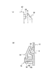
<第4実施形態>
図18〜図20は第4実施形態の説明図で、図18は実施形態の車両用室内照明装置におけるスポット照明部用の意匠カバーとその背後に装備する導光体と光源ユニットとの関係を示す表側から見た分解斜視図、図19は前記導光体の光の分岐経路を示す平面図、図20は前記光源ユニットと導光体の組合せにより照射される光の経路を模式的に示す斜視図である。
<Fourth embodiment>
18-20 is explanatory drawing of 4th Embodiment, FIG. 18 shows the relationship between the design cover for spot illumination parts in the vehicle interior lighting device of embodiment, the light guide body equipped behind it, and a light source unit. FIG. 19 is a plan view showing a light branching path of the light guide, and FIG. 20 schematically shows a light path irradiated by the combination of the light source unit and the light guide. It is a perspective view.
この実施形態の意匠カバー10Dには、中央部に1個だけスポット照明用の照射孔15が設けられている。また、導光体70は、図19に示すようにプリズム状のものであり、背面側に角度の付いた2つの平面状の光入射面71を有し、正面側に例えば湾曲した光出射面75を有している。そして、背面の光入射面71に入射した光源ユニット20からの光Sを、2つの方向へ分岐させて、1個の照射孔15を通して、異なる方向へ向けて斜めに照射するようになっている。その他の光源ユニット20等の構成は第1実施形態と同様である。
The
この実施形態では、プリズム状の導光体80を設けることにより、意匠カバー10Dに設けた1個の照射孔15から、異なる方向へスポット光Sを照射することができる。従って、光源ユニット20の個数を減らすことができ、その分だけ、重量やコストの低減が図れるし、配線数の低減から組付けの容易化や小型化および省スペース化を図ることができる。
In this embodiment, by providing the prismatic
また、共通の光源ユニット20からの光をプリズム状の導光体80によって、2つのスポット光Sに分割するので、光源ユニット20の光源であるLEDの部品固有のばらつきによる照明光の色むらや照度ばらつきを低減できる。
In addition, since the light from the common
なお、上述の各実施形態における導光体50、60、70、80に、光源ユニット20からの光の色相を変換する蛍光剤を含有させておけば、例えば、安価な青色LEDを使用しながら、導光体50、60、70、80内に含まれる蛍光剤によって青色光を白色光に変換させることができる。従って、そのようにすることで、コスト低減が可能となる。
If the light guides 50, 60, 70, and 80 in each of the above-described embodiments contain a fluorescent agent that converts the hue of light from the
また、上記第1〜第3実施形態では、意匠カバー10、10B、10Cに2つの照光部(照射孔15や意匠部11)を設け、導光体50、60、80で2つの方向に光源ユニット20からの光を分岐する場合を示したが、より多数の照光部に対して光を供給できるように、導光体50、60、80で3方向以上に光を分岐させてもよい。第4実施形態についても、同様に、3方向以上に光源ユニット20からの光を分岐するようにしてもよい。
Moreover, in the said 1st-3rd embodiment, two illumination parts (
10,10B,10C,10D 意匠カバー
11 意匠部(面状照光部)
15 スポット照射孔(照光部)
20 光源ユニット
25 出射口
50,60,70,80 導光体
51,61,71,81 光入射面
52,62,82 光分岐部
53,63,83 アーム部
55,65A,65B,75 光出射面
85 第1の光出射面
86 第2の光出射面
10, 10B, 10C, 10D Design cover 11 Design part (planar illumination part)
15 Spot irradiation hole (lighting part)
20
Claims (6)
前記光源ユニットの出射口と前記意匠カバーの複数の照光部との間に、前記光源ユニットの出射口から出射された光を複数の方向に分岐して各照光部に導く導光体を配置したことを特徴とする車両用室内照明装置。 A design cover attached to the ceiling wall of the vehicle interior, and a light source unit disposed behind the design cover, and a plurality of illuminations provided on the design cover for emitting light emitted from an exit port of the light source unit In the vehicle interior lighting device that irradiates the vehicle interior through the section,
A light guide body is arranged between the light source outlet and the plurality of illumination portions of the design cover to divide the light emitted from the light source outlet in a plurality of directions and guide the light to each illumination portion. The interior lighting device for vehicles characterized by the above-mentioned.
前記複数の照光部として、前記意匠カバーに、互いに離れた小さいエリアをそれぞれ照明するスポット照明用の複数の照射孔が設けられており、前記光源ユニットが、前記複数の照射孔からほぼ等距離の位置に配置され、前記導光体には、前記光源ユニットの出射口から出射された光が入射する光入射面と、該光入射面に入射した光を前記照射孔の数に対応した複数の方向に分岐する光分岐部と、該光分岐部で分岐された光を前記各照射孔に向けてそれぞれ導くアーム部と、該各アーム部の先端側にそれぞれ前記照射孔に対応して設けられることで、各アーム部を通って来た光を前記照射孔に向けて出射する光出射面と、が設けられていることを特徴とする車両用室内照明装置。 The vehicle interior lighting device according to claim 1,
As the plurality of illumination portions, a plurality of spot illumination holes for illuminating small areas separated from each other are provided in the design cover, and the light source unit is substantially equidistant from the plurality of illumination holes. The light guide is disposed at a position, and the light guide has a light incident surface on which light emitted from the light emission port of the light source unit is incident, and a plurality of light incident on the light incident surface corresponding to the number of irradiation holes. A light branching portion that branches in a direction, an arm portion that guides the light branched by the light branching portion toward each irradiation hole, and a tip end side of each arm portion, corresponding to each irradiation hole. Thus, the vehicle interior lighting device is provided with a light emitting surface that emits the light that has passed through each arm portion toward the irradiation hole.
前記複数の照光部として、前記意匠カバーに、互いに離れた小さいエリアをそれぞれ照明するスポット照明用の複数の照射孔が設けられており、前記光源ユニットが、前記複数の照射孔のうちの1つの照射孔に対向する位置に配置され、前記導光体には、前記光源ユニットの出射口から出射される光が入射する光入射面と、該光入射面に入射した光を前記照射孔の数に対応した複数の方向に分岐する光分岐部と、該光分岐部で分岐された光のうちの第1の方向に分岐された光を前記光源ユニットに対向する位置にある前記照射孔に向けて出射する第1の光出射面と、前記光分岐部で分岐された光のうちの他の方向に分岐された光をそれぞれ前記他の照射孔に向けて導くアーム部と、該各アーム部の先端側に前記各他の照射孔に対応して設けられることで、各アーム部を通って来た光を前記他の照射孔に向けてそれぞれ出射する第2の光出射面と、が設けられていることを特徴とする車両用室内照明装置。 The vehicle interior lighting device according to claim 1,
As the plurality of illumination parts, a plurality of irradiation holes for spot illumination that respectively illuminate small areas separated from each other are provided in the design cover, and the light source unit is one of the plurality of irradiation holes. The light guide is disposed at a position facing the irradiation hole, and the light guide has a light incident surface on which light emitted from the light emission port of the light source unit is incident, and the light incident on the light incident surface is the number of the irradiation holes. A light branching portion that branches in a plurality of directions corresponding to the light, and the light branched in the first direction among the lights branched by the light branching portion is directed to the irradiation hole at a position facing the light source unit A first light exit surface that emits light, an arm portion that guides the light branched in the other direction out of the light branched by the light branching portion toward the other irradiation holes, and each arm portion Provided on the front end side of each other corresponding to each of the other irradiation holes. Rukoto, the second light emitting surface for emitting respectively toward the light came through each arm portion to the other irradiation hole, indoor lighting device for a vehicle, characterized in that is provided.
前記複数の照光部として、前記意匠カバーに、小さいエリアを照明するスポット照明用の照射孔と、面状に光を放射する面状照光部とが設けられており、前記光源ユニットが、前記スポット照明用の照射孔に対向する位置に配置され、前記導光体には、前記光源ユニットの出射口から出射される光が入射する光入射面と、該光入射面に入射した光を2つに分岐する光分岐部と、該光分岐部で2つに分岐された光のうちの一方の光を前記照射孔に向けて出射する第1の光出射面と、前記光分岐部で2つに分岐された光のうちの他方の光を前記面状照光部に向けて導くアーム部と、該アーム部に前記面状照光部に対応して設けられることで、各アーム部を通って来た光を前記面状照光部に向けて面状に出射する第2の光出射面と、が設けられていることを特徴とする車両用室内照明装置。 The vehicle interior lighting device according to claim 1,
As the plurality of illumination parts, the design cover is provided with a spot illumination irradiation hole for illuminating a small area and a planar illumination part for emitting light in a planar shape, and the light source unit includes the spot light The light guide is disposed at a position opposite to the illumination hole, and the light guide has two light incident surfaces on which light emitted from the light emission port of the light source unit is incident and two light incident on the light incident surface. A light branching section that branches into two, a first light emitting surface that emits one of the lights branched into two at the light branching section toward the irradiation hole, and two at the light branching section An arm portion that guides the other of the branched light beams to the planar illumination portion, and the arm portion is provided corresponding to the planar illumination portion so that it passes through each arm portion. And a second light emitting surface for emitting the light in a planar shape toward the planar illumination portion. Indoor lighting device for a vehicle, characterized in that.
前記光源ユニットの出射口と前記意匠カバーの1個の照光部との間に、前記光源ユニットの出射口からの光を複数の方向へ分岐させて、前記1個の照光部を通して、異なる方向へ向けて照射するプリズム状の導光体を配置したことを特徴とする車両用室内照明装置。 A design cover attached to the ceiling wall of the vehicle interior, and a light source unit disposed behind the design cover, and the light emitted from the light emission port of the light source unit is provided on the design cover. In the vehicle interior lighting device that irradiates the vehicle interior through the illumination unit,
The light from the emission port of the light source unit is branched in a plurality of directions between the emission port of the light source unit and one illumination part of the design cover, and in different directions through the one illumination unit. A vehicular interior lighting device comprising a prismatic light guide that irradiates toward the vehicle.
前記光源ユニットに光源としてLEDが設けられると共に、前記導光体に、前記LEDからの光の色相を変換する蛍光剤が含有されていることを特徴とする車両用室内照明装置。 The vehicle interior lighting device according to any one of claims 1 to 5,
An interior lighting device for a vehicle, wherein an LED is provided as a light source in the light source unit, and a fluorescent agent that converts a hue of light from the LED is contained in the light guide.
Priority Applications (3)
| Application Number | Priority Date | Filing Date | Title |
|---|---|---|---|
| JP2007323218A JP2009143409A (en) | 2007-12-14 | 2007-12-14 | Vehicle interior lighting system |
| US12/330,078 US8777467B2 (en) | 2007-12-14 | 2008-12-08 | Vehicle interior lighting system |
| DE102008062051.3A DE102008062051B4 (en) | 2007-12-14 | 2008-12-12 | Vehicle interior lighting system |
Applications Claiming Priority (1)
| Application Number | Priority Date | Filing Date | Title |
|---|---|---|---|
| JP2007323218A JP2009143409A (en) | 2007-12-14 | 2007-12-14 | Vehicle interior lighting system |
Publications (1)
| Publication Number | Publication Date |
|---|---|
| JP2009143409A true JP2009143409A (en) | 2009-07-02 |
Family
ID=40690253
Family Applications (1)
| Application Number | Title | Priority Date | Filing Date |
|---|---|---|---|
| JP2007323218A Pending JP2009143409A (en) | 2007-12-14 | 2007-12-14 | Vehicle interior lighting system |
Country Status (3)
| Country | Link |
|---|---|
| US (1) | US8777467B2 (en) |
| JP (1) | JP2009143409A (en) |
| DE (1) | DE102008062051B4 (en) |
Cited By (1)
| Publication number | Priority date | Publication date | Assignee | Title |
|---|---|---|---|---|
| WO2013015450A1 (en) | 2011-07-27 | 2013-01-31 | Yazaki Corporation | Lighting structure of switch |
Families Citing this family (5)
| Publication number | Priority date | Publication date | Assignee | Title |
|---|---|---|---|---|
| DE102010023811B4 (en) * | 2010-06-15 | 2012-12-20 | Audi Ag | Lighting device for the interior of a motor vehicle |
| DE102011016417A1 (en) * | 2011-04-08 | 2012-10-11 | GM Global Technology Operations LLC (n. d. Gesetzen des Staates Delaware) | Luminous molding, in particular decorative part and / or trim part for a vehicle interior |
| FR3026691A1 (en) * | 2014-10-02 | 2016-04-08 | Valeo Vision | LIGHTING AND / OR SIGNALING SYSTEM FOR MOTOR VEHICLES |
| JP6559723B2 (en) * | 2017-01-27 | 2019-08-14 | 矢崎総業株式会社 | Lighting unit |
| JP2022505878A (en) | 2018-10-26 | 2022-01-14 | エリコン メテコ(ユーエス)インコーポレイテッド | Corrosion-resistant and wear-resistant nickel-based alloy |
Citations (2)
| Publication number | Priority date | Publication date | Assignee | Title |
|---|---|---|---|---|
| JP2006007856A (en) * | 2004-06-23 | 2006-01-12 | Toyoda Gosei Co Ltd | Lighting system |
| JP2006044567A (en) * | 2004-08-06 | 2006-02-16 | Mitsubishi Electric Corp | In-cabin illumination device |
Family Cites Families (5)
| Publication number | Priority date | Publication date | Assignee | Title |
|---|---|---|---|---|
| JPH0799345A (en) * | 1993-09-28 | 1995-04-11 | Nichia Chem Ind Ltd | Light emitting diode |
| JP4013536B2 (en) | 2001-12-11 | 2007-11-28 | 豊田合成株式会社 | Lighting device |
| JP4276138B2 (en) | 2004-06-21 | 2009-06-10 | アルパイン株式会社 | DVD audio playback apparatus and audio playback apparatus |
| JP2006232092A (en) | 2005-02-24 | 2006-09-07 | Toyoda Gosei Co Ltd | Lighting system |
| JP2007323218A (en) | 2006-05-31 | 2007-12-13 | Hitachi Ltd | Backup system |
-
2007
- 2007-12-14 JP JP2007323218A patent/JP2009143409A/en active Pending
-
2008
- 2008-12-08 US US12/330,078 patent/US8777467B2/en not_active Expired - Fee Related
- 2008-12-12 DE DE102008062051.3A patent/DE102008062051B4/en not_active Expired - Fee Related
Patent Citations (2)
| Publication number | Priority date | Publication date | Assignee | Title |
|---|---|---|---|---|
| JP2006007856A (en) * | 2004-06-23 | 2006-01-12 | Toyoda Gosei Co Ltd | Lighting system |
| JP2006044567A (en) * | 2004-08-06 | 2006-02-16 | Mitsubishi Electric Corp | In-cabin illumination device |
Cited By (1)
| Publication number | Priority date | Publication date | Assignee | Title |
|---|---|---|---|---|
| WO2013015450A1 (en) | 2011-07-27 | 2013-01-31 | Yazaki Corporation | Lighting structure of switch |
Also Published As
| Publication number | Publication date |
|---|---|
| US20090154183A1 (en) | 2009-06-18 |
| DE102008062051A1 (en) | 2009-06-25 |
| DE102008062051B4 (en) | 2020-02-06 |
| US8777467B2 (en) | 2014-07-15 |
Similar Documents
| Publication | Publication Date | Title |
|---|---|---|
| KR101748536B1 (en) | Vehicle light for lighting the interior of a vehicle | |
| CN106838759B (en) | Lighting device for vehicle | |
| EP2489550A2 (en) | Vehicle lamp | |
| US10583774B2 (en) | Vehicle lamp | |
| US11754250B2 (en) | Vehicle lamp | |
| KR101804311B1 (en) | Back light unit | |
| JP2009143409A (en) | Vehicle interior lighting system | |
| JP2019200928A (en) | Vehicular lighting fixture | |
| JP2011034887A (en) | Vehicular lamp | |
| US8277062B2 (en) | Lamp assembly and housing therefor | |
| JP6561053B2 (en) | Illumination system, in particular for an automotive lighting element, comprising a light emitting element offset from a light source | |
| US20080158900A1 (en) | Overhead console projector lamp optics | |
| US8882315B2 (en) | External rear-view mirror assembly having a housing comprising a circuit board supporting a plurality of light emitting diodes | |
| JP5169806B2 (en) | Lighting device | |
| KR20210080229A (en) | Automotive lighting and/or signaling device | |
| JP2016207396A (en) | Light source unit and luminaire | |
| CN108224351B (en) | Lighting unit | |
| WO2013102996A1 (en) | Vehicle interior illumination device | |
| JP2021017179A (en) | Ambient light | |
| US20160161079A1 (en) | 3d-effect led illuminating device with scattering system | |
| US11498480B2 (en) | Illuminating device for vehicle ceiling lamp | |
| KR101176509B1 (en) | Automotive LED lights indirect lighting | |
| JP2016187986A (en) | Vehicle interior material with lighting device | |
| JP2020047361A (en) | Vehicular marker lamp | |
| JP2014229534A (en) | Luminaire |
Legal Events
| Date | Code | Title | Description |
|---|---|---|---|
| A621 | Written request for application examination |
Free format text: JAPANESE INTERMEDIATE CODE: A621 Effective date: 20101028 |
|
| A977 | Report on retrieval |
Free format text: JAPANESE INTERMEDIATE CODE: A971007 Effective date: 20111221 |
|
| A131 | Notification of reasons for refusal |
Free format text: JAPANESE INTERMEDIATE CODE: A131 Effective date: 20120117 |
|
| A521 | Written amendment |
Free format text: JAPANESE INTERMEDIATE CODE: A523 Effective date: 20120224 |
|
| A02 | Decision of refusal |
Free format text: JAPANESE INTERMEDIATE CODE: A02 Effective date: 20120724 |