JP2017149357A - On-vehicle display device - Google Patents
On-vehicle display device Download PDFInfo
- Publication number
- JP2017149357A JP2017149357A JP2016035512A JP2016035512A JP2017149357A JP 2017149357 A JP2017149357 A JP 2017149357A JP 2016035512 A JP2016035512 A JP 2016035512A JP 2016035512 A JP2016035512 A JP 2016035512A JP 2017149357 A JP2017149357 A JP 2017149357A
- Authority
- JP
- Japan
- Prior art keywords
- vehicle
- display unit
- display
- unit
- screen
- Prior art date
- Legal status (The legal status is an assumption and is not a legal conclusion. Google has not performed a legal analysis and makes no representation as to the accuracy of the status listed.)
- Granted
Links
Images


Abstract
Description
本発明は、車室内の天井から吊り下げられ、情報を表示する車載表示装置に関する。 The present invention relates to an in-vehicle display device that is suspended from a ceiling in a vehicle interior and displays information.
所謂ミニバンなどの車両においては、1列目シートと2列目シートとの間の天井から吊り下げられ、2列目シートや3列目シートの乗員向けに情報を表示する表示部を有する車載表示装置が設けられたものがある。従来、こうした車載表示装置としては、天井から表示部が吊下げられる吊下げ位置と、表示部が天井に沿って格納される格納位置との間で表示部を変位させる変位機構を備えたものがある(例えば特許文献1参照)。 In a vehicle such as a so-called minivan, an in-vehicle display having a display unit that is suspended from the ceiling between the first row seat and the second row seat and displays information for passengers in the second row seat and the third row seat Some are provided with a device. Conventionally, as such an in-vehicle display device, there is one equipped with a displacement mechanism that displaces the display unit between a hanging position where the display unit is suspended from the ceiling and a storage position where the display unit is stored along the ceiling. Yes (see, for example, Patent Document 1).
ところで、特許文献1に記載の技術においては、車両走行中に2列目シートや3列目シートに乗員がいないときに車載表示装置が有効に活用されないという問題がある。
本発明の目的は、車両走行中に後席に乗員がいない場合であっても有効に活用することのできる車載表示装置を提供することにある。
By the way, in the technique described in Patent Document 1, there is a problem that the in-vehicle display device cannot be effectively used when there is no occupant in the second row seat or the third row seat while the vehicle is running.
An object of the present invention is to provide an in-vehicle display device that can be used effectively even when there is no occupant in the rear seat while the vehicle is traveling.
上記目的を達成するための車載表示装置は、車室内の天井から吊り下げられ、情報を表示する表示部を有する表示ユニットと、車室内の座席に着座した乗員が前記表示部の画面を視認可能な第1位置と、前記第1位置よりも車両のウィンドウに近接した位置であり、且つ前記ウィンドウに前記表示部の画面が対向する第2位置との間で前記表示ユニットを移動させる移動ユニットと、前記表示ユニットを前記第1位置から前記第2位置に移動させるべく前記移動ユニットの駆動を制御する駆動制御部と、前記表示ユニットが前記第2位置にあるときに、車外向けの情報を前記画面に表示させるべく前記表示部を制御する表示制御部と、を備えている。 An in-vehicle display device for achieving the above object is a display unit that has a display unit that is suspended from a ceiling in a vehicle interior and displays information, and a passenger seated in a seat in the vehicle cabin can visually recognize the screen of the display unit A moving unit that moves the display unit between the first position and a second position that is closer to the window of the vehicle than the first position and the screen of the display unit faces the window. A drive control unit that controls driving of the moving unit to move the display unit from the first position to the second position; and when the display unit is in the second position, A display control unit that controls the display unit to display on a screen.
同構成によれば、移動ユニットを駆動させることにより、第1位置と第2位置との間で表示ユニットを移動させることができる。このため、表示ユニットが第1位置にあるときには、座席に着座した乗員は表示部の画面を視認することができ、テレビや映画などを視ることができる。 According to this configuration, the display unit can be moved between the first position and the second position by driving the moving unit. For this reason, when the display unit is in the first position, an occupant seated in the seat can view the screen of the display unit, and can watch a television or a movie.
一方、車両走行中に表示ユニットが第2位置にあるときには、表示部の画面に車外向けの情報が表示される。このため、車両のウィンドウを通じて当該車外向けの情報を車外に向けて発信することができる。 On the other hand, when the display unit is in the second position during traveling of the vehicle, information for the outside of the vehicle is displayed on the screen of the display unit. For this reason, the information for the outside of the vehicle can be transmitted outside the vehicle through the window of the vehicle.
本発明によれば、車両走行中に後席に乗員がいない場合であっても車載表示装置を有効に活用することができる。 According to the present invention, the in-vehicle display device can be effectively used even when there is no passenger in the rear seat while the vehicle is traveling.
以下、図1〜図8を参照して、一実施形態について説明する。
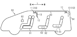
図1に示すように、本実施形態の車載表示装置(以下、表示装置10)が適用される車両90の室内には、車両の前後方向(以下、前後方向L)において前から順に、1列目シート91、2列目シート92、及び3列目シート93が設けられている。
Hereinafter, an embodiment will be described with reference to FIGS.
As shown in FIG. 1, the
図1及び図2に示すように、本実施形態の表示装置10は、車室内の天井80から吊り下げられ、情報を表示する四角板状の表示部12を有する表示ユニット11と、図1に実線にて示す第1位置と二点鎖線にて示す第2位置との間で表示ユニット11を移動させる移動ユニット20とを備えている。なお、図1においては、移動ユニット20の図示が省略されている。
As shown in FIGS. 1 and 2, the
上記第1位置は、1列目シート91と2列目シート92との間であって、後席(2列目シート92または3列目シート93)に着座した乗員が表示部12の画面13を視認可能な位置である。また、上記第2位置は、最後部座席である3列目シート93よりも後側であり、且つリアウィンドウ94に表示部12の画面13が対向する位置である。
The first position is between the
<移動ユニット20>
図3及び図4に示すように、天井80は、内張りとしてのルーフライナ81と、ルーフライナ81の上面に固定されてルーフライナ81を補強する補強プレート82とを有している。天井80の車幅方向Wの中央部には、前後方向Lに沿って延在する貫通孔83が形成されている。
<
As shown in FIGS. 3 and 4, the
図4及び図5に示すように、補強プレート82の上面には、車幅方向Wの両側から貫通孔83を挟むとともに前後方向Lに沿って延在する一対のレール部21が設けられている。レール部21は、前後方向Lにおいて1列目シート91と2列目シート92との間の位置から3列目シート93よりも後方の位置まで延在している。
As shown in FIGS. 4 and 5, the upper surface of the reinforcing
図4及び図5に示すように、一対のレール部21上には、移動体22が前後方向Lに移動可能に設けられている。
図4に示すように、移動体22は、本体部23、本体部23により回動可能に支持された連結軸24、及び連結軸24の両端に固定されて一対のレール部21上を転動する一対のローラ25を備えている。連結軸24の中央部にはウォームホイール29が固定されている。
As shown in FIGS. 4 and 5, a
As shown in FIG. 4, the moving
図3及び図4に示すように、本体部23の内部には、移動用モータ26が固定されている。移動用モータ26の出力軸27は後方に向けて突出しており、同出力軸27の先端部には、上記ウォームホイール29に噛合されるウォーム28が固定されている。ウォーム28及びウォームホイール29によりウォームギアが構成されている。移動用モータ26を駆動してウォーム28が回転すると、ウォームホイール29を介して連結軸24が回転駆動されることで一対のローラ25が一対のレール部21上を転動する。
As shown in FIGS. 3 and 4, a moving
上記レール部21及び移動体22によって移動ユニット20が構成されている。
図5に示すように、レール部21の前端及び後端には、移動体22の前方及び後方への移動を規制するストッパ211,212がそれぞれ設けられている。
The
As shown in FIG. 5,
<表示ユニット11>
図3及び図4に示すように、移動体22の本体部23の底壁には、下方に向けて突出する支持部17が連結されている。支持部17は天井80の貫通孔83を貫通して車室内に突出しており、同支持部17の下端には、表示部12を格納する格納部14が連結されている。
<
As shown in FIGS. 3 and 4, a
図3に示すように、格納部14の後端部には車幅方向Wに沿って延在する回動軸15が設けられており、同回動軸15には、表示部12の一辺が固定されている。回動軸15の一端には、揺動用モータ16の出力軸が連結されている。この揺動用モータ16を駆動して回動軸15を回動することにより、表示部12は図3に実線にて示す位置(天井80から表示部12が吊り下げられた位置、以下、吊り下げ位置)と、同図に二点鎖線にて示す位置(格納部14に格納された位置、以下、格納位置)との間で揺動される。
As shown in FIG. 3, a
上記表示部12、格納部14、回動軸15、及び揺動用モータ16により表示ユニット11が構成されている。
次に、表示部12、揺動用モータ16、及び移動用モータ26に対して電力を供給するとともに表示部12に対して画像信号を送信するワイヤハーネス41の配索構造について説明する。
The
Next, a wiring structure of the
図3に示すように、ワイヤハーネス41は、移動体22の本体部23の前壁に形成された挿通孔231に挿通されている。ワイヤハーネス41の一部は、移動用モータ26に電気的に接続されている。また、ワイヤハーネス41の一部は、支持部17の内部を通って揺動用モータ16及び表示部12に電気的に接続されている。
As shown in FIG. 3, the
ワイヤハーネス41における移動体22の外側(同図の前側)に位置する部分は、コルゲート管42によって覆われている。
移動体22の本体部23の前壁には、コルゲート管42の一端部421を保持する筒状の保持部材43が固設されている。保持部材43の内周面に形成された複数の突起44がコルゲート管42の外周面の凹部に係合されることにより、コルゲート管42が保持部材43により保持されている。
A portion of the
A
図3及び図5に示すように、補強プレート82の上面には、コルゲート管42に覆われたワイヤハーネス41を出し入れ自在に収容する収容部45が設けられている。
図5に示すように、収容部45は、車幅方向Wにおいて一対のレール部21と並んで設けられてコルゲート管42に覆われたワイヤハーネス41のうちU字状に曲げられた余長部分を収容する余長収容部46、及び余長収容部46と上記保持部材43との間に設けられてワイヤハーネス41を湾曲させつつ案内する案内部47を備えている。
As shown in FIG. 3 and FIG. 5, an
As shown in FIG. 5, the
また、案内部47の下方には、コルゲート管42の他端部422から前方に向けて延在するワイヤハーネス41の引き出し部411を、コルゲート管42に覆われたワイヤハーネス41と交差させる交差部48が設けられている。
Further, below the
なお、上記引き出し部411は、例えばドアピラーの内部を通って後述する電子制御装置50に電気的に接続されている。
こうした構造によれば、上記移動体22が後方に移動する際には、コルゲート管42に覆われたワイヤハーネス41が収容部45から後方に向けて円滑に送り出される。このとき、ワイヤハーネス41のU字状の余長部分が、図5に実線にて示す位置から同図に二点鎖線にて示す位置へと移動する。
In addition, the said drawer | drawing-out part 411 is electrically connected to the
According to such a structure, when the moving
これとは反対に、上記移動体22が前方に移動する際には、コルゲート管42に覆われたワイヤハーネス41が収容部45に送り入れられる。このとき、ワイヤハーネス41のU字状の余長部分が、図5に二点鎖線にて示す位置から同図に実線にて示す位置へと移動する。
On the contrary, when the moving
表示部12の表示制御、揺動用モータ16の駆動制御、及び移動用モータ26の駆動制御は、電子制御装置50により行われる。
図6に示すように、電子制御装置50は、中央処理制御装置(CPU)、各種プログラムやマップなどを予め記憶した読出専用メモリ(ROM)、CPUの演算結果などを一時記憶するランダムアクセスメモリ(RAM)、タイマカウンタ、入力インターフェース、出力インターフェースなどを備えて構成されている。
Display control of the
As shown in FIG. 6, the
電子制御装置50は、表示ユニット11を第1位置と第2位置との間で移動させるべく移動用モータ26の駆動を制御する他、表示ユニット11を吊下げ位置と格納位置との間で揺動させるべく揺動用モータ16の駆動を制御する駆動制御部51を備えている。
The
また、電子制御装置50は、表示ユニット11が第2位置にあるときに、車外向けの情報を画面13に表示させるべく表示部12を制御する表示制御部52とを備える。
電子制御装置50には、表示装置10を操作する操作スイッチ60の操作信号、車外の照度を検出する照度センサ61の検出信号、2列目シート92及び3列目シート93に乗員が着座しているか否かをそれぞれ検出する着座センサ62,63の検出信号が入力される。また、電子制御装置50には、車両のシフトレバーのシフト位置を検出するシフト位置センサ64の検出信号、前後方向Lにおける移動体22の位置を検出する移動体位置センサ65の検出信号、表示部12の位置(揺動角度)を検出する表示部位置センサ66が入力される。
In addition, the
The
なお、操作スイッチ60は、押しボタン式のスイッチとして運転席の周囲に設けてもよいし、車両のナビゲーションシステムのディスプレイなどに静電容量式のスイッチ、所謂タッチスイッチとして設けてもよい。着座センサ62,63は周知の感圧センサにより構成されている。また、移動体位置センサ65及び表示部位置センサ66は例えば周知の近接センサにより構成されている。
The
次に、図7を参照して、表示装置制御の処理手順について説明する。
表示装置制御は、操作スイッチ60がON操作されたときに、電子制御装置50の駆動制御部51及び表示制御部52により実行される。
Next, a processing procedure for display device control will be described with reference to FIG.
The display device control is executed by the
図7に示すように、この一連の処理では、まず、ステップS1において、着座センサ62,63の検出信号に基づいて、後席(2列目シート92または3列目シート93)に乗員が着座しているか否かが判断される。
As shown in FIG. 7, in this series of processing, first, in step S1, an occupant sits in the rear seat (
ここで、肯定判断された場合(ステップS1:「YES」)には、後席に乗員が着座しており、当該車両90の乗員により表示ユニット11が利用される可能性があるとして、この一連の処理が終了される。
Here, when an affirmative determination is made (step S1: “YES”), the passenger is seated in the rear seat, and the
一方、ステップS1において否定判断された場合(ステップS1:「NO」)には、次に、ステップS2に移行し、表示部位置センサ66の検出信号に基づいて、表示部12が格納位置にあるか否かが判断される。
On the other hand, if a negative determination is made in step S1 (step S1: “NO”), the process proceeds to step S2, and the
ここで、否定判断された場合(ステップS2:「NO」)には、次にステップS3に移行し、表示部12を格納位置にすべく揺動用モータ16の格納駆動制御が実行される。
この格納駆動制御では、表示部位置センサ66の検出信号に基づいて、表示部12が格納位置にあると判断されるまで揺動用モータ16の駆動が継続される。
Here, when a negative determination is made (step S2: “NO”), the process proceeds to step S3, and storage drive control of the
In the storage drive control, the drive of the
一方、ステップS2において、肯定判断された場合(ステップS2:「YES」)には、次に、ステップS4に移行し、表示ユニット11を第2位置に移動させるべく移動用モータ26の駆動制御が実行される。
On the other hand, when an affirmative determination is made in step S2 (step S2: “YES”), the process proceeds to step S4, where drive control of the moving
移動用モータ26の駆動制御では、移動体位置センサ65の検出結果に基づいて、移動体22が第2位置に相当する位置にあると判断されるまで移動用モータ26の駆動が継続される。
In the drive control of the moving
移動用モータ26の駆動制御が終了すると、次に、ステップS5に移行し、表示部12を吊り下げ位置にすべく揺動用モータ16の吊り下げ駆動制御が実行される。
この吊り下げ駆動制御では、表示部位置センサ66の検出信号に基づいて、表示部12が吊り下げ位置にあると判断されるまで揺動用モータ16の駆動が継続される。
When the drive control of the
In this suspension drive control, the drive of the
吊り下げ駆動制御が終了すると、次に、ステップS6に移行し、表示制御が実行される。
この表示制御では、後述する車外向けの情報を画面13に表示すべく表示部12が制御される。そして、この一連の処理が終了される。
When the suspension drive control ends, the process proceeds to step S6, where display control is executed.
In this display control, the
次に、図8を参照して、上記車外向けの情報の一例について説明する。
図8(a)に示す情報は、当該車両90の後続車両に追い越しを促す旨の文字や記号の情報である。
Next, an example of information for the outside of the vehicle will be described with reference to FIG.
The information shown in FIG. 8A is information on characters and symbols that prompt the vehicle following the
図8(b)に示す情報は、当該車両90に乳児が乗っていることを示す文字や絵の情報である。
図8(c)に示す情報は、当該車両90の目的地及びルートを示す文字や記号の情報である。この場合、車両90に搭載されたナビゲーションシステムにて設定される目的地及びルートの情報に基づいて情報が逐次更新されるようにすることが好ましい。
The information shown in FIG. 8B is character or picture information indicating that an infant is on the
The information shown in FIG. 8C is information on characters and symbols indicating the destination and route of the
なお、画面13に表示される情報の切り替えは、操作スイッチ60の操作を通じて行われる。
以上説明した本実施形態に係る車載表示装置によれば、以下に示す作用効果が得られるようになる。
Note that switching of information displayed on the
According to the vehicle-mounted display device according to the present embodiment described above, the following effects can be obtained.
(1)表示装置10は、車室内の天井80から吊り下げられ、情報を表示する表示部12を有する表示ユニット11を備えている。また、表示装置10は、車室内の2列目シート92または3列目シート93に着座した乗員が表示部12の画面13を視認可能な第1位置と、第1位置よりも車両90のリアウィンドウ94に近接した位置であり、且つリアウィンドウ94に表示部12の画面13が対向する第2位置との間で表示ユニット11を移動させる移動ユニット20を備えている。また、表示装置10は、表示ユニット11を第1位置から第2位置に移動させるべく移動ユニット20の駆動を制御する駆動制御部51、及び表示ユニット11が第2位置にあるときに、車外向けの情報を画面13に表示させるべく表示部12を制御する表示制御部52を備えている。
(1) The
こうした構成によれば、移動ユニット20を駆動させることにより、第1位置と第2位置との間で表示ユニット11を移動させることができる。このため、表示ユニット11が第1位置にあるときには、後席(2列目シート92や3列目シート93)に着座した乗員は表示部12の画面13を視認することができ、テレビや映画などを視ることができる。
According to such a configuration, the
一方、車両走行中に表示ユニット11が第2位置にあるときには、表示部12の画面13に車外向けの情報が表示される。このため、車両90のリアウィンドウ94を通じて当該車外向けの情報を車外に向けて発信することができる。したがって、車外に向けて情報を効果的に発信することができる。
On the other hand, when the
よって、車両走行中に後席に乗員がいない場合であっても表示装置10を有効に活用することのできる。
(2)駆動制御部51は、第1位置と第2位置との間に乗員が存在する場合には移動用モータ26の駆動を禁止する。
Therefore, the
(2) The
こうした構成によれば、第1位置と第2位置との間に乗員が存在しており、当該車両90の乗員が表示ユニット11を利用する可能性がある場合には、表示ユニット11が第2位置に移動されない。換言すれば、表示ユニット11が車室内において利用されない場合に限って表示ユニット11が第2位置に移動される。したがって、当該車両90の乗員が表示ユニット11を利用できなくなるという不都合の発生を回避できる。
According to such a configuration, when there is an occupant between the first position and the second position and there is a possibility that the occupant of the
(3)第2位置は、最後部座席(3列目シート93)よりも後側であり、且つ車両90のリアウィンドウ94に表示部12の画面13が対向する位置である。このため、車両走行中において後方からの画面13の視認性を高めることができる。
(3) The second position is a position behind the rearmost seat (the third row seat 93) and the
(4)駆動制御部51は、着座センサ62,63により後席(2列目シート92、3列目シート93)に乗員が着座していることが検出された場合には移動用モータ26の駆動を禁止する。
(4) When the
こうした構成によれば、後席に乗員が着座しているか否かを着座センサ62,63により的確に検出することができる。そして、後席に乗員が着座していることが検出された場合には、移動用モータ26の駆動が禁止される。このため、当該車両90の乗員が表示ユニット11を利用できなくなるという不都合の発生を周知の着座センサ62,63を用いて容易に回避できる。
According to such a configuration, whether or not an occupant is seated in the rear seat can be accurately detected by the
(5)駆動制御部51は、移動用モータ26の駆動に先立ち、表示部12が吊下げ位置にある場合には、表示部12を格納位置にさせるべく揺動用モータ16の駆動を制御する。
(5) When the
こうした構成によれば、移動用モータ26の駆動に先立ち、表示部12が吊下げ位置にある場合には、揺動用モータ16が駆動されることで表示部12が格納位置にされる。これにより、表示部12が格納位置にある状態で移動用モータ26が駆動されることとなる。したがって、表示ユニット11が第1位置から第2位置に移動される際に表示部12が後席のヘッドレストなどの障害物に干渉することを抑制できる。
According to such a configuration, prior to driving the
(6)表示制御部52は、当該車両90に関する情報及び当該車両90の乗員に関する情報を情報として画面13に表示させるべく表示部12を制御する。
こうした構成によれば、当該車両90に関する情報や当該車両90の乗員に関する情報が情報として車外に向けて表示される。このため、当該車両90やその乗員に関する情報を車外に向けて積極的に発信することができる。
(6) The
According to such a configuration, information related to the
(7)表示制御部52は、当該車両90に関する情報として、後続車両に追い越しを促す旨の文字や記号の情報を画面13に表示させるべく表示部12を制御する。
こうした構成によれば、夜間などにおいても後続車両の運転手に対して当該車両90に関する情報を効果的に発信することができる。
(7) The
According to such a configuration, information regarding the
(8)表示制御部52は、当該車両90に関する情報として、目的地及びルートを示す文字や記号の情報を画面13に表示させるべく表示部12を制御する。
こうした構成によれば、当該車両90の目的地及びルートを示す文字や記号が画面13を通じて後続車両に向けて発信される。このため、例えば高速道路において、当該車両90の後続車両の運転手は先行車両である当該車両90の目的地及びルートを把握することができる。したがって、後続車両の運転手は、先行車両との車間距離を一定に保つアダプティブクルーズコントロール走行をする際に、当該車両90を自身が追従する対象車両とするか否かを判断する際の有効な判断材料を得ることができる。
(8) The
According to such a configuration, characters and symbols indicating the destination and route of the
<変形例>
なお、上記実施形態は、例えば以下のように変更することもできる。
・照度センサ61の検出信号に応じて表示部12のバックライトの輝度を可変設定することもできる。すなわち、昼間のように照度の高いときには夜間のように照度の低いときに比べてバックライトの輝度を高く設定することが画面13の視認性を高める上で好ましい。
<Modification>
In addition, the said embodiment can also be changed as follows, for example.
The brightness of the backlight of the
・表示装置制御の実行中、表示部12が吊り下げ位置にあるときに、シフトレバーのシフト位置がリバース位置に変更された場合には、表示装置制御の実行を停止するとともに、表示部12を格納位置にすべく揺動用モータ16を駆動することもできる。この場合、運転手がリアウィンドウ94越しに後方確認する際に天井から吊り下げられた表示部12が障害となることを回避できる。
If the shift position of the shift lever is changed to the reverse position when the
・上記実施形態では、操作スイッチ60がON操作されることにより、表示装置制御が実行されたが、例えば、運転席に運転手が着座しており、後席には乗員が着座しておらず、且つ全てのドアが閉じられたことをもって、表示装置制御が自動的に実行されるようにすることもできる。この場合、操作スイッチ60の操作を省略することができる。あるいは、操作スイッチ60自体を省略することができる。
In the above embodiment, the display device control is executed by turning on the
・上記表示制御において、当該車両90の室温を示す文字情報を表示部12の画面13に表示するようにしてもよい。
・当該車両90が一定速度を維持するクルーズコントロール走行をする際に、図8(c)に示す情報に加えて、あるいは同情報と交互に、当該車両90がクルーズコントロール走行中である旨を示す文字や記号の情報を表示部12に表示するようにしてもよい。この場合、当該車両90の後続車両の運転手は、先行車両である当該車両90の目的地及びルートに加えて、当該車両90がクルーズコントロール走行をしていることを把握することができる。したがって、後続車両の運転手は、アダプティブクルーズコントロール走行をする際に、当該車両90を自身が追従する対象車両とするか否かを判断する際のより有効な判断材料を得ることができる。
In the display control, character information indicating the room temperature of the
When the
・上記実施形態では、着座センサ62,63により後席に乗員が着座しているか否かを検出するようにした。これに代えて、車室内に赤外線センサなどを設けるとともに第1位置と第2位置との間に乗員が存在するか否かを検出するようにしてもよい。
In the above embodiment, the
・上記実施形態では、移動ユニット20により、1列目シート91と2列目シート92との間の第1位置と、3列目シート93よりも後方の第2位置との間で表示ユニット11を移動させる構成について例示した。これに代えて、上記第1位置と、第1位置よりも2列目シート92の側方に位置するサイドウィンドウに近接した位置であり、サイドウィンドウに画面13が対向する第2位置との間で表示ユニット11を移動させるようにしてもよい。この場合、画面13が車幅方向Wの外側を向くように移動体22に対して支持部17を回動させる機構を追加すればよい。
In the above embodiment, the
10…表示装置、11…表示ユニット、12…表示部、13…画面、14…格納部、15…回動軸、16…揺動用モータ、17…支持部、20…移動ユニット、21…レール部、211,212…規制部、22…移動体、23…本体部、231…挿通孔、24…連結軸、25…ローラ、26…移動用モータ、27…出力軸、28…ウォーム、29…ウォームホイール、41…ワイヤハーネス、411…引き出し部、42…コルゲート管、421…一端部、422…他端部、43…保持部材、44…突起、45…収容部材、46…余長収容部、47…案内部、48…交差部、50…電子制御装置、51…駆動制御部、52…表示制御部、60…操作スイッチ、61…照度センサ、62…着座センサ、63…着座センサ、64…シフト位置センサ、65…移動体位置センサ、66…表示部位置センサ、80…天井、81…ルーフライナ、82…補強プレート、83…貫通孔、90…車両、91〜93…シート、94…リアウィンドウ。
DESCRIPTION OF
Claims (6)
車室内の座席に着座した乗員が前記表示部の画面を視認可能な第1位置と、前記第1位置よりも車両のウィンドウに近接した位置であり、且つ前記ウィンドウに前記表示部の画面が対向する第2位置との間で前記表示ユニットを移動させる移動ユニットと、
前記表示ユニットを前記第1位置から前記第2位置に移動させるべく前記移動ユニットの駆動を制御する駆動制御部と、
前記表示ユニットが前記第2位置にあるときに、車外向けの情報を前記画面に表示させるべく前記表示部を制御する表示制御部と、を備える、
車載表示装置。 A display unit that has a display unit that is hung from the ceiling in the passenger compartment and displays information;
A first position where an occupant seated in a seat in the vehicle cabin can visually recognize the screen of the display section, and a position closer to the vehicle window than the first position, and the screen of the display section faces the window. A moving unit that moves the display unit to and from a second position;
A drive control unit for controlling the driving of the moving unit to move the display unit from the first position to the second position;
A display control unit that controls the display unit to display information directed to the outside of the vehicle on the screen when the display unit is in the second position;
In-vehicle display device.
請求項1に記載の車載表示装置。 The drive control unit prohibits driving of the moving unit when an occupant is present between the first position and the second position;
The in-vehicle display device according to claim 1.
前記駆動制御部は、前記着座センサにより前記後席に乗員が着座していることが検出された場合には前記移動ユニットの駆動を禁止する、
請求項2に記載の車載表示装置。 A seating sensor for detecting whether a passenger is seated in the rear seat of the vehicle;
The drive control unit prohibits the driving of the moving unit when the seating sensor detects that an occupant is seated in the rear seat;
The in-vehicle display device according to claim 2.
前記第2位置は、前記最後部座席よりも後側であり、且つ車両のリアウィンドウに前記表示部の画面が対向する位置である、
請求項1〜請求項3のいずれか一項に記載の車載表示装置。 The first position is a front side of the rearmost seat, and is a position where an occupant seated in the rearmost seat can visually recognize the screen of the display unit,
The second position is a position behind the rear seat and the screen of the display unit faces the rear window of the vehicle.
The vehicle-mounted display apparatus as described in any one of Claims 1-3.
前記駆動制御部は、前記移動ユニットの駆動に先立ち、前記表示部が前記吊下げ位置にある場合には、前記表示部を前記格納位置に変位させるべく前記変位機構の駆動を制御する、
請求項1〜請求項4のいずれか一項に記載の車載表示装置。 The display unit is a displacement that displaces the display unit between a hanging position where the display unit is suspended from the ceiling and a storage position where the display unit is stored along the ceiling. Equipped with a mechanism,
The drive control unit controls driving of the displacement mechanism to displace the display unit to the storage position when the display unit is in the hanging position prior to driving the moving unit.
The vehicle-mounted display apparatus as described in any one of Claims 1-4.
請求項1〜請求項5のいずれか一項に記載の車載表示装置。 The display control unit controls the display unit to display at least one of information on the vehicle and information on an occupant of the vehicle on the screen as the information.
The vehicle-mounted display apparatus as described in any one of Claims 1-5.
Priority Applications (1)
| Application Number | Priority Date | Filing Date | Title |
|---|---|---|---|
| JP2016035512A JP6536429B2 (en) | 2016-02-26 | 2016-02-26 | In-vehicle display device |
Applications Claiming Priority (1)
| Application Number | Priority Date | Filing Date | Title |
|---|---|---|---|
| JP2016035512A JP6536429B2 (en) | 2016-02-26 | 2016-02-26 | In-vehicle display device |
Publications (2)
| Publication Number | Publication Date |
|---|---|
| JP2017149357A true JP2017149357A (en) | 2017-08-31 |
| JP6536429B2 JP6536429B2 (en) | 2019-07-03 |
Family
ID=59740364
Family Applications (1)
| Application Number | Title | Priority Date | Filing Date |
|---|---|---|---|
| JP2016035512A Active JP6536429B2 (en) | 2016-02-26 | 2016-02-26 | In-vehicle display device |
Country Status (1)
| Country | Link |
|---|---|
| JP (1) | JP6536429B2 (en) |
Cited By (3)
| Publication number | Priority date | Publication date | Assignee | Title |
|---|---|---|---|---|
| CN112937460A (en) * | 2019-12-11 | 2021-06-11 | 现代自动车株式会社 | Display moving device |
| JP2021532338A (en) * | 2018-07-27 | 2021-11-25 | バイエリシエ・モトーレンウエルケ・アクチエンゲゼルシヤフト | Display devices and vehicles |
| CN114103821A (en) * | 2020-08-27 | 2022-03-01 | 本田技研工业株式会社 | Moving body |
Citations (9)
| Publication number | Priority date | Publication date | Assignee | Title |
|---|---|---|---|---|
| JPH0414549U (en) * | 1990-05-29 | 1992-02-05 | ||
| JPH08272321A (en) * | 1995-03-31 | 1996-10-18 | Toyoda Gosei Co Ltd | External display device of vehicle |
| JPH11198720A (en) * | 1998-01-14 | 1999-07-27 | Harness Syst Tech Res Ltd | Display device |
| JP3067824U (en) * | 1999-09-29 | 2000-04-11 | 安夫 種田 | Vehicle ready marking device |
| US20010022553A1 (en) * | 1999-01-29 | 2001-09-20 | Silviu Pala | Rear view and multi-media system for vehicles |
| JP2003237477A (en) * | 2002-02-13 | 2003-08-27 | Mazda Motor Corp | Overhead console structure for vehicle |
| JP2004123002A (en) * | 2002-10-04 | 2004-04-22 | Matsushita Electric Ind Co Ltd | Image display device |
| JP2005096624A (en) * | 2003-09-25 | 2005-04-14 | Sony Corp | Moving device for monitor, monitor system and vehicle |
| JP2010202101A (en) * | 2009-03-05 | 2010-09-16 | Panasonic Corp | On-vehicle display |
-
2016
- 2016-02-26 JP JP2016035512A patent/JP6536429B2/en active Active
Patent Citations (9)
| Publication number | Priority date | Publication date | Assignee | Title |
|---|---|---|---|---|
| JPH0414549U (en) * | 1990-05-29 | 1992-02-05 | ||
| JPH08272321A (en) * | 1995-03-31 | 1996-10-18 | Toyoda Gosei Co Ltd | External display device of vehicle |
| JPH11198720A (en) * | 1998-01-14 | 1999-07-27 | Harness Syst Tech Res Ltd | Display device |
| US20010022553A1 (en) * | 1999-01-29 | 2001-09-20 | Silviu Pala | Rear view and multi-media system for vehicles |
| JP3067824U (en) * | 1999-09-29 | 2000-04-11 | 安夫 種田 | Vehicle ready marking device |
| JP2003237477A (en) * | 2002-02-13 | 2003-08-27 | Mazda Motor Corp | Overhead console structure for vehicle |
| JP2004123002A (en) * | 2002-10-04 | 2004-04-22 | Matsushita Electric Ind Co Ltd | Image display device |
| JP2005096624A (en) * | 2003-09-25 | 2005-04-14 | Sony Corp | Moving device for monitor, monitor system and vehicle |
| JP2010202101A (en) * | 2009-03-05 | 2010-09-16 | Panasonic Corp | On-vehicle display |
Cited By (4)
| Publication number | Priority date | Publication date | Assignee | Title |
|---|---|---|---|---|
| JP2021532338A (en) * | 2018-07-27 | 2021-11-25 | バイエリシエ・モトーレンウエルケ・アクチエンゲゼルシヤフト | Display devices and vehicles |
| JP7332633B2 (en) | 2018-07-27 | 2023-08-23 | バイエリシエ・モトーレンウエルケ・アクチエンゲゼルシヤフト | display and vehicle |
| CN112937460A (en) * | 2019-12-11 | 2021-06-11 | 现代自动车株式会社 | Display moving device |
| CN114103821A (en) * | 2020-08-27 | 2022-03-01 | 本田技研工业株式会社 | Moving body |
Also Published As
| Publication number | Publication date |
|---|---|
| JP6536429B2 (en) | 2019-07-03 |
Similar Documents
| Publication | Publication Date | Title |
|---|---|---|
| JP6981244B2 (en) | Display device for vehicles and vehicles | |
| US10239528B2 (en) | Vehicle and method of controlling the vehicle | |
| CN103079935B (en) | For car assisted method and apparatus of parking | |
| JP4985164B2 (en) | Parking assistance device and program for parking assistance device | |
| US10639993B2 (en) | Vehicle shade assembly | |
| JP2015016803A (en) | Vehicle control system | |
| JP7147169B2 (en) | vehicle display | |
| JP2015202769A (en) | Vehicular image display apparatus and vehicular image display method | |
| JP6536429B2 (en) | In-vehicle display device | |
| JP2007152997A (en) | Seat position automatic adjustment device | |
| US20150185999A1 (en) | Display control apparatus and control method for vehicle | |
| JP2008201221A (en) | Automobile upper structure | |
| WO2016104298A1 (en) | View control device for vehicle | |
| JP2008107238A (en) | Navigation device for vehicle | |
| JP2005096624A (en) | Moving device for monitor, monitor system and vehicle | |
| KR101953132B1 (en) | Steering apparatus, Vehicle having the same and method for controlling the same | |
| JP2020117103A (en) | Vehicular display device | |
| EP3225465B1 (en) | Viewing control device for vehicle | |
| KR102430170B1 (en) | Vehicle and controlling method thereof | |
| JP6430888B2 (en) | Visual control device for vehicle | |
| JP2011116145A (en) | Automobile antitheft device | |
| JP2008074360A (en) | Control device of vehicular seat | |
| JP7345007B1 (en) | Control device | |
| JP7073002B2 (en) | Display system | |
| JP2016117432A (en) | Vehicle visibility control device |
Legal Events
| Date | Code | Title | Description |
|---|---|---|---|
| A621 | Written request for application examination |
Free format text: JAPANESE INTERMEDIATE CODE: A621 Effective date: 20180423 |
|
| A131 | Notification of reasons for refusal |
Free format text: JAPANESE INTERMEDIATE CODE: A131 Effective date: 20190226 |
|
| A977 | Report on retrieval |
Free format text: JAPANESE INTERMEDIATE CODE: A971007 Effective date: 20190227 |
|
| A521 | Request for written amendment filed |
Free format text: JAPANESE INTERMEDIATE CODE: A523 Effective date: 20190412 |
|
| TRDD | Decision of grant or rejection written | ||
| A01 | Written decision to grant a patent or to grant a registration (utility model) |
Free format text: JAPANESE INTERMEDIATE CODE: A01 Effective date: 20190507 |
|
| A61 | First payment of annual fees (during grant procedure) |
Free format text: JAPANESE INTERMEDIATE CODE: A61 Effective date: 20190520 |
|
| R150 | Certificate of patent or registration of utility model |
Ref document number: 6536429 Country of ref document: JP Free format text: JAPANESE INTERMEDIATE CODE: R150 |
|
| R250 | Receipt of annual fees |
Free format text: JAPANESE INTERMEDIATE CODE: R250 |
|
| R250 | Receipt of annual fees |
Free format text: JAPANESE INTERMEDIATE CODE: R250 |