JP2017142142A - Particle detection sensor, portable gas monitor, and particle detection method - Google Patents
Particle detection sensor, portable gas monitor, and particle detection method Download PDFInfo
- Publication number
- JP2017142142A JP2017142142A JP2016023170A JP2016023170A JP2017142142A JP 2017142142 A JP2017142142 A JP 2017142142A JP 2016023170 A JP2016023170 A JP 2016023170A JP 2016023170 A JP2016023170 A JP 2016023170A JP 2017142142 A JP2017142142 A JP 2017142142A
- Authority
- JP
- Japan
- Prior art keywords
- waveform
- particle
- mass concentration
- light
- unit
- Prior art date
- Legal status (The legal status is an assumption and is not a legal conclusion. Google has not performed a legal analysis and makes no representation as to the accuracy of the status listed.)
- Pending
Links
- 239000002245 particle Substances 0.000 title claims abstract description 255
- 238000001514 detection method Methods 0.000 title claims abstract description 190
- 238000012545 processing Methods 0.000 claims abstract description 105
- 238000012937 correction Methods 0.000 claims abstract description 70
- 238000005259 measurement Methods 0.000 claims abstract description 59
- 239000012530 fluid Substances 0.000 claims abstract description 17
- 238000000034 method Methods 0.000 claims description 65
- 230000008569 process Effects 0.000 claims description 61
- 239000007788 liquid Substances 0.000 claims description 16
- 230000000593 degrading effect Effects 0.000 abstract description 3
- 238000004364 calculation method Methods 0.000 description 36
- 238000006243 chemical reaction Methods 0.000 description 34
- 239000003570 air Substances 0.000 description 30
- 238000003860 storage Methods 0.000 description 18
- 238000010586 diagram Methods 0.000 description 15
- 230000007704 transition Effects 0.000 description 13
- 230000003321 amplification Effects 0.000 description 12
- 238000003199 nucleic acid amplification method Methods 0.000 description 12
- 239000012080 ambient air Substances 0.000 description 10
- 238000010438 heat treatment Methods 0.000 description 8
- 238000000149 argon plasma sintering Methods 0.000 description 7
- 230000008859 change Effects 0.000 description 7
- 230000007246 mechanism Effects 0.000 description 7
- 230000006866 deterioration Effects 0.000 description 6
- 230000003287 optical effect Effects 0.000 description 6
- 230000002238 attenuated effect Effects 0.000 description 4
- 239000000470 constituent Substances 0.000 description 4
- 239000000463 material Substances 0.000 description 4
- 230000000630 rising effect Effects 0.000 description 4
- 239000000443 aerosol Substances 0.000 description 3
- 230000007423 decrease Effects 0.000 description 3
- 230000004048 modification Effects 0.000 description 3
- 238000012986 modification Methods 0.000 description 3
- 239000011347 resin Substances 0.000 description 3
- 229920005989 resin Polymers 0.000 description 3
- 239000004065 semiconductor Substances 0.000 description 3
- 239000000428 dust Substances 0.000 description 2
- 230000006870 function Effects 0.000 description 2
- 238000001746 injection moulding Methods 0.000 description 2
- -1 pollen Substances 0.000 description 2
- 239000004417 polycarbonate Substances 0.000 description 2
- 230000004044 response Effects 0.000 description 2
- 238000005070 sampling Methods 0.000 description 2
- 239000000779 smoke Substances 0.000 description 2
- 230000006641 stabilisation Effects 0.000 description 2
- 238000011105 stabilization Methods 0.000 description 2
- 229920000122 acrylonitrile butadiene styrene Polymers 0.000 description 1
- 239000003990 capacitor Substances 0.000 description 1
- 230000015556 catabolic process Effects 0.000 description 1
- 238000006731 degradation reaction Methods 0.000 description 1
- 238000013461 design Methods 0.000 description 1
- 230000008034 disappearance Effects 0.000 description 1
- 238000009826 distribution Methods 0.000 description 1
- 230000000694 effects Effects 0.000 description 1
- 238000004049 embossing Methods 0.000 description 1
- 230000014509 gene expression Effects 0.000 description 1
- 239000011521 glass Substances 0.000 description 1
- 230000005484 gravity Effects 0.000 description 1
- 230000020169 heat generation Effects 0.000 description 1
- 238000004519 manufacturing process Methods 0.000 description 1
- 239000003973 paint Substances 0.000 description 1
- 239000000049 pigment Substances 0.000 description 1
- 229920000515 polycarbonate Polymers 0.000 description 1
- 238000003672 processing method Methods 0.000 description 1
- 238000013139 quantization Methods 0.000 description 1
- 238000010791 quenching Methods 0.000 description 1
- 239000007787 solid Substances 0.000 description 1
- 238000004381 surface treatment Methods 0.000 description 1
- 230000001360 synchronised effect Effects 0.000 description 1
- 238000011144 upstream manufacturing Methods 0.000 description 1
- XLYOFNOQVPJJNP-UHFFFAOYSA-N water Substances O XLYOFNOQVPJJNP-UHFFFAOYSA-N 0.000 description 1
Images


Abstract
Description
本発明は、気体または液体である流体中に含まれる粒子を測定する粒子検出センサ、当該粒子検出センサを備える携帯型気体モニタ、及び、粒子検出方法に関する。 The present invention relates to a particle detection sensor that measures particles contained in a fluid that is a gas or a liquid, a portable gas monitor including the particle detection sensor, and a particle detection method.
光散乱式粒子検出センサは、投光素子と受光素子とを備える光電式センサであり、測定対象の気体を取り込んで投光素子の光を当該気体に照射し、その散乱光によって気体に含まれる粒子の有無を検出するものである。このような光散乱式検出センサは、例えば、大気中に浮遊するホコリ、花粉、煙等の粒子を検出することができる。 The light scattering particle detection sensor is a photoelectric sensor including a light projecting element and a light receiving element, takes in a gas to be measured, irradiates the light of the light projecting element, and is contained in the gas by the scattered light. It detects the presence or absence of particles. Such a light scattering detection sensor can detect particles such as dust, pollen, and smoke floating in the atmosphere.
この種の光散乱式粒子検出センサを含む機器として、当該光散乱式粒子検出センサからの検知信号を用いて、大気中の単位体積当たりの粒子の量(濃度)を検出するものが知られている(例えば、特許文献1参照)。 As a device including this type of light scattering particle detection sensor, a device that detects the amount (concentration) of particles per unit volume in the atmosphere using a detection signal from the light scattering particle detection sensor is known. (For example, refer to Patent Document 1).
しかしながら、上記従来の光散乱式粒子検出センサの構成では、上昇気流を生成する発熱部及び投光素子の消費電力が問題となる。また、発熱部の発熱開始から上昇気流安定までの応答速度が低いため、低消費電力化が困難であるという問題がある。 However, in the configuration of the conventional light scattering particle detection sensor, the power consumption of the heat generating unit and the light projecting element that generate the rising airflow becomes a problem. Further, since the response speed from the start of heat generation of the heat generating portion to the stabilization of the rising airflow is low, there is a problem that it is difficult to reduce power consumption.
そこで、本発明は、検出精度を劣化させずに消費電力を低減することができる粒子検出センサ等を提供することを目的とする。 Therefore, an object of the present invention is to provide a particle detection sensor or the like that can reduce power consumption without degrading detection accuracy.
上記目的を達成するため、本発明の一態様に係る粒子検出センサは、気体または液体である流体中に含まれる粒子を検出する粒子検出センサであって、検知領域に光を投光する投光素子、及び、前記検知領域に位置する前記粒子によって散乱された光を受光する受光素子と、前記検知領域に前記気体または前記液体の流れを発生させる流速発生部と、前記流速発生部を間欠駆動する駆動制御部と、前記受光素子からの出力を示す時系列の信号を信号処理することにより、前記流体中に含まれる前記粒子の質量濃度を算出する信号処理部とを備え、前記信号処理部は、前記検知領域における前記気体または前記液体の流れが定常状態となっている場合の基準となるリファレンス波形を取得し、前記駆動制御部が前記流速発生部を間欠駆動している場合の前記時系列の信号に対応した測定波形を取得し、前記リファレンス波形と前記測定波形とについて、波形が略一致する場合、補正処理を行うことなく前記質量濃度を算出し、当該波形が略一致しない場合、前記補正処理を行って前記質量濃度を算出する。 In order to achieve the above object, a particle detection sensor according to one embodiment of the present invention is a particle detection sensor that detects particles contained in a fluid that is a gas or a liquid, and projects light on a detection region. An element, a light receiving element that receives light scattered by the particles located in the detection region, a flow rate generation unit that generates a flow of the gas or the liquid in the detection region, and an intermittent drive of the flow rate generation unit And a signal processing unit that calculates a mass concentration of the particles contained in the fluid by performing signal processing on a time-series signal indicating an output from the light receiving element, and the signal processing unit. Obtains a reference waveform as a reference when the flow of the gas or the liquid in the detection region is in a steady state, and the drive control unit intermittently drives the flow rate generation unit. Measurement waveform corresponding to the time-series signal is obtained, and when the reference waveform and the measurement waveform substantially match, the mass concentration is calculated without performing correction processing, and the waveform is substantially If they do not match, the correction process is performed to calculate the mass concentration.
また、本発明の一態様に係る携帯型気体モニタは、前記記載の粒子検出センサと、前記粒子検出センサを駆動するための電池と、前記粒子検出センサで算出された前記質量濃度を表示する表示部とを備える。 A portable gas monitor according to an aspect of the present invention includes a particle detection sensor described above, a battery for driving the particle detection sensor, and a display that displays the mass concentration calculated by the particle detection sensor. A part.
また、本発明の一態様に係る粒子検出方法は、検知領域に光を投光する投光素子、前記検知領域に位置する粒子によって散乱された光を受光する受光素子、及び前記検知領域に気体または液体の流れを発生させる流速発生部を有する粒子検出センサを用いて、前記気体または液体である流体中に含まれる前記粒子を検出する粒子検出方法であって、前記検知領域における前記気体または前記液体の流れが定常状態となっている場合の基準となるリファレンス波形を取得するステップと、前記流速発生部を間欠駆動している状態で、前記受光素子からの出力を示す時系列の信号に対応した測定波形を取得するステップと、前記リファレンス波形と前記測定波形とについて、波形が略一致する場合、補正処理を行うことなく前記流体中に含まれる前記粒子の質量濃度を算出し、当該波形が略一致しない場合、前記補正処理を行って前記質量濃度を算出するステップとを含む。 In addition, a particle detection method according to one embodiment of the present invention includes a light projecting element that projects light onto a detection region, a light receiving device that receives light scattered by particles located in the detection region, and a gas that is disposed on the detection region. Alternatively, a particle detection method for detecting the particles contained in the fluid that is the gas or the liquid using a particle detection sensor having a flow velocity generation unit that generates a liquid flow, the gas or the gas in the detection region Corresponding to the time-series signal indicating the output from the light receiving element in the step of acquiring a reference waveform as a reference when the liquid flow is in a steady state and the flow velocity generating unit being intermittently driven When the waveform substantially matches between the step of obtaining the measured waveform and the reference waveform and the measured waveform, they are included in the fluid without performing correction processing. Calculating the mass concentration of the serial particles, if the waveform is not substantially match, and calculating the mass concentration by performing the correction process.
本発明によれば、検出精度を劣化させずに消費電力を低減することができる。 According to the present invention, power consumption can be reduced without degrading detection accuracy.
以下では、本発明の実施の形態に係る粒子検出センサ等について、図面を用いて詳細に説明する。なお、以下に説明する実施の形態は、いずれも本発明の好ましい一具体例を示すものである。したがって、以下の実施の形態で示される数値、形状、材料、構成要素、構成要素の配置及び接続形態、並びに、ステップ及びステップの順序などは、一例であり、本発明を限定する趣旨ではない。よって、以下の実施の形態における構成要素のうち、本発明の最上位概念を示す独立請求項に記載されていない構成要素については、任意の構成要素として説明される。 Below, the particle | grain detection sensor etc. which concern on embodiment of this invention are demonstrated in detail using drawing. Note that each of the embodiments described below shows a preferred specific example of the present invention. Therefore, numerical values, shapes, materials, components, arrangement and connection forms of components, and steps and order of steps shown in the following embodiments are merely examples, and are not intended to limit the present invention. Therefore, among the constituent elements in the following embodiments, constituent elements that are not described in the independent claims showing the highest concept of the present invention are described as optional constituent elements.
また、各図は、模式図であり、必ずしも厳密に図示されたものではない。また、各図において、同じ構成部材については同じ符号を付し、重複する説明は省略または簡略化する場合がある。さらに、以下において、略一致等の表現を用いている。例えば、略一致とは、完全に一致することを意味するだけでなく、実質的に一致することも意味する。すなわち、「略」とは、数%程度の誤差を含む。 Each figure is a mimetic diagram and is not necessarily illustrated strictly. Moreover, in each figure, the same code | symbol is attached | subjected about the same structural member, and the overlapping description may be abbreviate | omitted or simplified. Further, in the following, expressions such as substantially coincidence are used. For example, “substantially match” not only means that they completely match, but also means that they substantially match. That is, “substantially” includes an error of about several percent.
(実施の形態)
[1.構成]
まず、本発明の実施の形態に係る粒子検出センサの全体構成について説明する。
(Embodiment)
[1. Constitution]
First, the overall configuration of the particle detection sensor according to the embodiment of the present invention will be described.
図1は、本実施の形態に係る粒子検出センサ1の構成の一例を示すブロック図である。
FIG. 1 is a block diagram showing an example of the configuration of the
粒子検出センサ1は、車両等の移動体に搭載され、当該粒子検出センサ1の周辺に漂う空気(以下、周辺空気と称する)に含まれる粒子の質量濃度を測定する。例えば、周辺空気には粒径が10μm以下の微小なホコリ、花粉、煙、PM2.5等の粒子が含まれ、粒子検出センサ1はこれら粒子の質量濃度を粒径区分毎に測定することが可能である。
The
なお、以下では、「流体中の粒子の質量濃度」を、単に「質量濃度」と記載する場合がある。 In the following, “mass concentration of particles in fluid” may be simply referred to as “mass concentration”.
同図に示すように、粒子検出センサ1は、センサ部10と信号処理部20とを備え、センサ部10の検知領域DAに位置する粒子2からの散乱光に基づいて、周辺空気の質量濃度を測定する。また、粒子検出センサ1は、さらに、粒子検出センサ1が備える各構成に対して電源を供給する電源部30を備える。この電源部30は、例えば、粒子検出センサ1の外部から供給された電圧を所望の電圧に変換するレギュレータ等により構成される。
As shown in the figure, the
以下、粒子検出センサ1の各構成について、具体的に説明する。
Hereinafter, each structure of the particle |
[1−1.センサ部]
センサ部10は、粒子検出センサ1の測定対象である周辺空気を取り込んで、取り込んだ周辺空気に光を照射し、その散乱光の光強度を示す信号(ここでは電流信号)を出力する、光電式センサ(光散乱式粒子検出センサ)である。つまり、センサ部10は、取り込んだ周辺空気に含まれる粒子2に応じた時系列の信号を出力する。
[1-1. Sensor unit]
The
具体的には、本実施の形態では、センサ部10は、投光系11と受光系12と筐体13と気流発生部15とを備え、筐体13の流入口18から流出口19までの粒子流路に設けられた検知領域DAに位置する粒子2からの散乱光に応じた信号を出力する。投光系11、受光系12及び検知領域DAは、外光が照射されないように、筐体13に収容されている。
Specifically, in the present embodiment, the
検知領域DAは、測定対象の気体に含まれる粒子2(エアロゾル)を検知するためのエアロゾル検知領域(エアロゾル測定部)であり、投光系11の光軸Pと受光系12の光軸Qとが交差する交点を含む、例えばφ2mm程度の領域である。つまり、検知領域DAは、投光系11の光が投光される空間領域と投光系11の光が粒子2に当たって発生した散乱光を受光系12に導くための空間領域とが重なる空間領域である。
The detection area DA is an aerosol detection area (aerosol measurement unit) for detecting particles 2 (aerosol) contained in the gas to be measured, and includes an optical axis P of the
投光系11は、検知領域DAに光を投光する光学素子からなり、本実施の形態では、投光素子111と、投光素子111の前方(光投光側)に配置された投光レンズ112とを有する。
The light projecting
投光素子111は、検知領域DAに光を投光する、例えばLED(Light Emitting Diode)や半導体レーザ等の固体発光素子である。投光素子111は、例えば、赤外光、青色光、緑色光、赤色光または紫外光等の所定の波長の光を投光し、2波長以上の混合波を投光してもよい。本実施の形態では、粒子2による光の散乱強度に鑑みて、投光素子111として、例えば、400nm〜1000nmの波長の光を投光する砲弾型のLEDが用いられる。
The
なお、投光素子111から投光された光の波長が短いほど、粒径の小さな粒子2を検出しやすくなる。また、投光素子111の投光制御方式は特に限定されるものではなく、投光素子111から投光される光は、DC駆動による連続光またはパルス光等とすることができる。また、投光素子111から投光される光の光強度は、時間的に変化していてもよい。
In addition, it becomes easy to detect the particle | grains 2 with a small particle size, so that the wavelength of the light projected from the
投光レンズ112は、投光素子111の前方かつ投光系11の光軸P上に配置され、投光素子111から投光された光を検知領域DAに向けて進行させるように構成されている。例えば、投光レンズ112は、投光素子111から投光された光を検知領域DAに集光する集光レンズであり、PC(polycarbonate)等の透明樹脂またはガラスによって形成される。つまり、投光素子111から投光された光は、投光レンズ112を介して検知領域DAに到達する。この際、検知領域DAに粒子2が位置する場合、当該粒子2によって投光素子111からの光が散乱される。
The
受光系12は、検知領域DAからの光を受光する光学素子からなり、本実施の形態では、受光素子121と、受光素子121の前方(光入射側)に配置された受光レンズ122とを有する。検知領域DAに粒子2が位置する場合、当該粒子2によって散乱された光(散乱光)は、受光系12によって受光される。
The
受光素子121は、検知領域DAに位置する粒子2によって散乱された光を受光する。具体的には、受光素子121は、受光した光を電気信号に変換する光電変換素子であり、本実施の形態では、投光素子111が投光する光に感度を有する、フォトダイオード及びフォトトランジスタの少なくとも一方を有する。つまり、受光素子121は、受光した光強度に応じた信号(ここでは電流信号)を出力する。なお、受光素子121は、例えば、フォトICダイオードまたは光電子増倍管などを有してもよい。
The
受光レンズ122は、検知領域DAと受光素子121との間に配置され、検知領域DAに位置する粒子2による散乱光を受光素子121に集光するように構成されている。例えば、受光レンズ122は、検知領域DAに位置する粒子2によって散乱された光を受光素子121に集束させる集光レンズであり、投光レンズ112と同様の材質により形成される。
The
筐体13は、遮光性を有し、粒子2を含む周辺空気(気体)が流れる筒状の空間領域である粒子流路が設けられた部材である。例えば、筐体13は、迷光を減衰させやすいように、少なくとも内面が黒色面である。具体的には、筐体13の内面は、光の減衰率が高く、かつ、光を鏡面反射する。なお、筐体13の内面における反射は、鏡面反射でなくてもよく、光の一部が散乱反射されてもよい。
The
ここで、迷光とは、粒子2によって散乱された光以外の光であり、具体的には、投光素子111が投光した光のうち検知領域DAにおいて粒子2に散乱されることなく、筐体13内を進行する光等である。また、迷光には、粒子流路によって筐体13の内部に進入した外光も含まれる。
Here, the stray light is light other than the light scattered by the particles 2, and specifically, the light projected by the
筐体13は、例えば、ABS樹脂などの樹脂材料を用いた射出成形により形成される。このとき、例えば、黒色の顔料または染料を添加した樹脂材料を用いて筐体13を形成することで、筐体13の内面を黒色面にして迷光の減衰を図ることができる。あるいは、射出成形後に筐体13の内面に黒色塗料を塗布することで、筐体13の内面を黒色面にして迷光の減衰を図ることができる。また、筐体13の内面にシボ加工などの表面処理を行うことにより、迷光の減衰を図ることができる。
The
筐体13には、上述したように流入口18及び流出口19が設けられている。このため、周辺空気は、流入口18から筐体13の内部に進入し、粒子流路を通って検知領域DAに導かれ、流出口19から筐体13の外部に流出する。
The
なお、本実施の形態において、粒子流路の流路方向(粒子流路を気体が流れる方向)は、図1の紙面上下方向としているが、図1の紙面垂直方向としてもよい。つまり、本実施の形態では、粒子流路の流路軸は、投光系11及び受光系12の各光軸が通る平面上に存在するように設定しているが、当該平面と直交するように設定されていてもよい。
In the present embodiment, the flow direction of the particle flow path (the direction in which gas flows in the particle flow path) is the vertical direction on the paper surface of FIG. 1, but may be the vertical direction on the paper surface of FIG. That is, in the present embodiment, the flow path axis of the particle flow path is set to exist on a plane through which each optical axis of the light projecting
気流発生部15は、例えば、ファン(小型扇風機)で構成されており、当該ファンを稼動させることにより粒子流路に気流を発生させる流速発生部である。上記ファンを起動させると、粒子流路の気流速度は低速(速度略0)から徐々に高速となり、所定の期間経過後に一定となる。気流発生部15による気流の発生により、粒子検出センサ1の周辺空気が流入口18から筐体13内部に引き込まれるため、気流発生部15を設けない場合に比べて、センサ部10内に多くの粒子2を取り込むことができる。
The
気流発生部15は、粒子検出センサ1の低消費電力化を目的として、後述する駆動制御部により間欠駆動される。ただし、上記間欠駆動により、気流発生部15による気流が発生する期間(気流発生モード)と気流発生部15による気流が発生しない期間(気流消失モード)とが一定周期で繰り返される。そして、気流発生モードにおいて、検知領域DAを通過する粒子2が検出される。ここで、粒子検出センサ1が粒子2の質量濃度を高精度に測定するには、気流発生モードにおいて、安定した気流速度で気流を発生させることが重要となる。
The
この観点から、気流発生部15は、駆動制御部からの駆動信号に対して即応性を有する駆動素子で構成されていることが好ましく、ファンで構成されるほか、マイクロポンプまたは直流電動モータなどを含んでいてもよい。これらによっても、上記駆動信号により、高速に粒子流路に気流を発生させることが可能となる。なお、気流発生部15は、粒子流路内の流入口18側から流出口19側に向けて気流を発生させるようにセンサ部10内に設置されていればよい。
From this point of view, the
また、気流発生部15は、加熱機構で構成されていてもよい。この場合には、加熱機構周囲の気体を加熱することにより、粒子流路に気流を発生させる。具体的には、加熱機構が周囲の気体を加熱すると、加熱された気体は、膨張して密度が小さくなることにより重力と逆方向の上方向に移動する。つまり、加熱機構により、上方向の気流(上昇気流)が発生する。この気流が粒子流路の気体を流すことにより、粒子流路に気流が生じることとなる。なお、加熱機構を有する気流発生部15は、上昇気流を発生させることから、図1に示すように粒子流路の下方部分に設置されることが好ましい。また、加熱機構により気流を発生させる場合、上述したファン、マイクロポンプまたは直流電動モータにより気流を発生させる場合と比較して、気流発生モード開始時から気流速度が安定するまでの期間が長いという特徴を有している。この観点からも、本発明に係る気流発生部15としては、ファン、マイクロポンプまたは直流電動モータなどを含むことが好ましい。
Moreover, the
[1−2.信号処理部]
信号処理部20は、気流発生部15および投光素子111を間欠駆動する。また信号処理部20は、上記間欠駆動によりセンサ部10で取得された受光素子121からの出力を示す時系列の信号を信号処理することにより、流体中(本実施の形態では気体中)に含まれる粒子2の質量濃度を算出する。具体的には、信号処理部20は、受光素子121から出力された信号(本実施の形態では電流信号)に対してアナログ信号処理を施し、さらに、アナログ信号処理後の信号に対してデジタル信号処理を施すことにより、上記の質量濃度を算出する。
[1-2. Signal processor]
The
図1に示すように、信号処理部20は、アナログ信号処理を施すアナログ信号処理部21と、デジタル信号処理を施す汎用MPU22とを備える。
As shown in FIG. 1, the
アナログ信号処理部21は、アナログ回路により構成され、本実施の形態では、受光素子121から出力された電流信号に対して各種のアナログ信号処理を施すことにより、当該電流信号に基づく電圧信号を出力する。ここで、各種のアナログ信号処理とは、例えば、電流(I)を電圧(V)に変換するI/V変換、入力された信号の所望の周波数帯域を通過させるバンドパスフィルタ処理、及び、入力された信号を増幅して出力する増幅処理である。アナログ信号処理部21は、I/V変換を行うIV変換部211と、バンドパスフィルタ処理及び増幅処理を行う増幅部212とを含む。
The analog
なお、アナログ信号処理部21は、ここに例示した各処理に限らず、さらに他の信号処理(例えば、ハイパスフィルタ処理、ローパスフィルタ処理、及び、減衰処理等)を行う構成であってもよい。
The analog
IV変換部211は、受光素子121から出力された電流信号をI/V変換することにより、当該電流信号に応じた電圧信号を生成する。このように電流信号を電圧信号に変換することにより、以降の信号処理の容易化が図られるとともに、IV変換部211の後段に接続された増幅部212の設計の容易化が図られる。
The
増幅部212は、IV変換部211で生成された電圧信号の所定の帯域を増幅する。具体的には、増幅部212は、当該電圧信号に含まれる周波数成分のうち所定の帯域の周波数成分を、他の帯域の周波数成分よりも高い増幅率で増幅する。ここで、所定の帯域とは、例えば、センサ部10の粒子流路を流れる気体の流速v1に対応する周波数f1を中心周波数、帯域幅をfbwとする帯域である。なお、fbwは所定の周波数であってもよいし、電圧信号のノイズに応じて適宜設定される周波数であってもよい。
The
増幅部212は、例えば、図1に示すように、IV変換部211から出力された電圧信号に含まれる周波数成分のうち所定の帯域の周波数成分を通過させるバンドパスフィルタ215と、バンドパスフィルタ215を通過した周波数成分からなる信号を増幅する増幅器216とを含む。なお、バンドパスフィルタ215及び増幅器216の接続順はこれに限らず、増幅器216がバンドパスフィルタ215より前段に設けられていてもよい。
For example, as illustrated in FIG. 1, the amplifying
このような構成により、アナログ信号処理部21は、受光素子121からの出力を示し、かつ、検知領域DAに位置する粒子2に対応するパルス状の波形を含む時系列の電圧信号を出力する。
With such a configuration, the analog
ここで、粒子2に対応したパルス状の波形とは、検知領域DAを通過する粒子2の速度及び粒径等に対応した正弦波、または、それに類似の波形である。ただし、例えば、大粒径の粒子2と小粒径の粒子2とが同じタイミングで検知領域DAを通過する場合等には、その限りではない。 Here, the pulse-like waveform corresponding to the particle 2 is a sine wave corresponding to the velocity and particle size of the particle 2 passing through the detection area DA, or a waveform similar thereto. However, this is not the case, for example, when the large particle 2 and the small particle 2 pass through the detection area DA at the same timing.
汎用MPU22は、センサ部10の気流発生部15および投光素子111を間欠駆動する。また、汎用MPU22は、デジタル回路により構成され、上記間欠駆動の間にアナログ信号処理部21から出力された電圧信号を用いて、センサ部10の粒子流路に流れる気体に含まれる粒子の質量濃度を算出する。この汎用MPU22は、例えば、集積回路であるシステムLSIにより実現され、以下で説明する機能ブロック毎に個別に1チップ化されてもよいし、一部または全てを含むように1チップ化されてもよい。
The general-
また、汎用MPU22は、システムLSIに限るものではなく、専用回路または汎用プロセッサで実現してもよい。また、汎用MPU22は、LSI製造後にプログラムすることが可能なFPGA(Field Programmable Gate Array)、またはLSI内部の回路セルの接続や設定を再構成可能なリコンフィギュラブル・プロセッサを利用してもよい。
The general-
汎用MPU22は、図1に示すように、AD変換部221と、演算部222と、記憶部223と、駆動制御部224とを機能ブロックとして有する。駆動制御部224は、駆動信号を気流発生部15および投光素子111に出力することにより、気流発生部15および投光素子111を駆動する。また、汎用MPU22は、AD変換部221で生成したデジタルデータを用いて、センサ部10の粒子流路内に流れる気体に含まれる粒子についての種々の分析を行う。この種々の分析とは、例えば、粒子の質量濃度に限らず、当該粒子の粒径の算出、当該粒子の同定等が含まれてもかまわない。
As shown in FIG. 1, the general-
以下、汎用MPU22の各機能ブロックについて、詳細に説明する。
Hereinafter, each functional block of the general-
駆動制御部224は、粒子検出センサ1の低消費電力化を目的として、気流発生部15および投光素子111に対して、断続的に駆動信号を出力する。より具体的には、気流発生部15は、駆動制御部224からの駆動信号がオン状態(例えば駆動電圧がハイレベルの状態)に切り替わった場合に、粒子流路への気流発生を開始させ、オフ状態(例えば駆動電圧がローレベルの状態)に切り替わった場合に、粒子流路への気流発生を停止させる。つまり、駆動制御部224は、上記駆動信号のオン/オフを繰り返すことで、気流発生部15を間欠駆動する。
The
また、駆動制御部224は、気流発生部15の間欠駆動と同期させて、投光素子111に駆動信号を供給してもよい。より具体的には、駆動制御部224は、気流発生部15の動作時に投光素子111を発光させ、気流発生部15の非動作時に投光素子111を消光させるような駆動信号を、投光素子111に供給する。これにより、気流発生部15の間欠駆動と連動して投光素子111が間欠発光するので、粒子検出センサ1の消費電力を、より低減できる。
Further, the
さらに、図1には図示していないが、駆動制御部224は、気流発生部15の間欠駆動と同期させて、アナログ信号処理部21に駆動信号を供給してもよい。より具体的には、駆動制御部224は、気流発生部15の動作時に増幅部212へ電源電圧を供給させ、気流発生部15の非動作時に増幅部212への電源電圧を停止させるような駆動信号を、アナログ信号処理部21に供給する。これにより、気流発生部15の間欠駆動と連動して増幅部212が間欠動作するので、粒子検出センサ1の消費電力を、より低減できる。
Further, although not shown in FIG. 1, the
AD変換部221は、増幅部212で増幅された電圧信号をサンプリング(標本化)及び量子化する。言い換えると、当該AD変換部221は、アナログ信号処理部21から出力されたアナログの電圧信号をAD(Analog to Digital)変換することにより、当該電圧信号に対応する時系列のデジタルデータを生成する。つまり、AD変換部221は、受光素子121から出力された電流信号に基づく時系列のデジタルデータを生成する。
The
本実施の形態では、AD変換部221は、汎用MPU22に予め組み込まれたAD変換モジュールであり、当該汎用MPU22のアナログ入力端子に入力された電圧信号をデジタルデータに変換する。例えば、AD変換部221は、汎用MPU22のアナログ入力端子に入力された0.0〜5.0Vの範囲の電圧信号を、所定のサンプリング周期でサンプリングする。その後、AD変換部221は、サンプリングされた電圧信号の電圧を10ビットのデジタル値に変換することにより、上記の時系列のデジタルデータを生成する。
In the present embodiment, the
演算部222は、AD変換部221で生成されたデジタルデータを用いて、センサ部10の粒子流路に流れる気体に含まれる粒子2の質量濃度を算出する。なお、演算部222による処理の詳細については、後述する。
The
記憶部223は、演算部222が質量濃度を算出するための各種の情報を記憶する。記憶部223は、半導体メモリ等の記憶装置により実現され、本実施の形態では、汎用MPU22に予め組み込まれたメモリ領域である。なお、記憶部223は、汎用MPU22とは別体の記憶装置として設けられていてもかまわない。また、記憶部223が記憶する各種の情報の詳細については、後述する。
The
なお、駆動制御部224は、汎用MPU22に含まれていなくてもよく、汎用MPU22と異なる処理部で構成されていてもよい。
Note that the
[2.動作]
次に、粒子検出センサ1の動作について説明する。
[2. Operation]
Next, the operation of the
[2−1.センサ部]
まず、センサ部10の動作について説明する。
[2-1. Sensor unit]
First, the operation of the
気流発生部15が稼動すると、筐体13内の粒子流路に気流が生じる。これに伴い、周辺空気中の粒子は、粒子流路の流入口18から筐体13の内部に進入し、粒子の検知領域DAを通過して、粒子流路の流出口19から筐体13の外部に流出される。この際、検知領域DAに位置する粒子2によって、投光系11から投光された光が散乱される。
When the air
粒子2によって散乱された光が受光素子121に入射すると、受光素子121によって受光量(受光した散乱光の光強度)に応じた電流信号が出力される。
When the light scattered by the particles 2 enters the
図2は、受光素子121から出力される電流信号の一例を示す波形図である。
FIG. 2 is a waveform diagram showing an example of a current signal output from the
同図に示す電流信号の波形には、4つのパルス状の波形W1〜W4が含まれる。具体的には、当該電流信号の波形には、ピーク値I3を有する波形W1と、ピーク値I2を有する波形W2と、ピーク値I1を有する波形W3及びW4とが含まれる。なお、これらの波形W1〜W4には、ノイズによる波形WNが重畳されている。 The waveform of the current signal shown in the figure includes four pulse waveforms W1 to W4. Specifically, the waveform of the current signal includes a waveform W1 having a peak value I3, a waveform W2 having a peak value I2, and waveforms W3 and W4 having a peak value I1. Note that a waveform WN due to noise is superimposed on these waveforms W1 to W4.
波形W1〜W4は、気流が粒子流路を流れることに伴って検知領域DAを通過する粒子2に対応し、それぞれが対応する粒子2の粒径に応じたピーク値を有する。ここで、波形W1〜W3はそれぞれ1つのピークのみを有するのに対し、波形W4は2つのピークを有する。つまり、波形W1〜W3はそれぞれ1つの粒子に対応する単一波形であるのに対し、波形W4は2つの同一粒径の粒子に対応する2つの波形が合成された合成波形となっている。 The waveforms W1 to W4 correspond to the particles 2 that pass through the detection area DA as the airflow flows through the particle flow paths, and each has a peak value corresponding to the particle size of the corresponding particle 2. Here, each of the waveforms W1 to W3 has only one peak, whereas the waveform W4 has two peaks. That is, each of the waveforms W1 to W3 is a single waveform corresponding to one particle, whereas the waveform W4 is a combined waveform in which two waveforms corresponding to two particles having the same particle diameter are combined.
[2−2.信号処理部]
次に、信号処理部20の動作について、説明する。
[2-2. Signal processor]
Next, the operation of the
IV変換部211が、受光素子121から出力された電流を電圧に変換することにより、電圧信号を生成する。つまり、受光素子121から出力された電流信号は電圧信号へと変換される。
The
次に、増幅部212が、当該電圧信号を所定の帯域で増幅する。
Next, the
その後、AD変換部221が、増幅部212で増幅されたアナログ信号である電圧信号をデジタル変換(AD変換)することにより、デジタルデータを生成する。つまり、AD変換部221は、サンプリング及び量子化することにより、受光系12からの出力を示すセンサ信号がデジタル化された時系列のデジタルデータを生成して、演算部222に出力する。
After that, the
図3は、AD変換部221によって生成されたデジタルデータの一例を示す波形図である。具体的には、同図には、図2に示した電流信号が信号処理されることで生成されたデジタルデータの波形図が示されている。
FIG. 3 is a waveform diagram illustrating an example of digital data generated by the
同図に示すデジタルデータは、例えば、10ビットの時系列のデジタルデータである。なお、デジタルデータの波形はステップ状の波形であるが、同図では、当該ステップの幅が非常に小さいものとして、見た目上曲線で図示している。また、同図では、デジタルデータの各サンプルのデジタル値を電圧に換算して図示している。これらの事項については、以降の波形図においても同様である。 The digital data shown in the figure is, for example, 10-bit time series digital data. Although the waveform of the digital data is a step-like waveform, in the same figure, it is assumed that the width of the step is very small and is shown by an apparent curve. In the same figure, the digital value of each sample of digital data is converted into a voltage. These matters are the same in the following waveform diagrams.
同図に示すように、AD変換部221によって生成されたデジタルデータの波形では、ノイズによる波形WN(図2参照)がフィルタリングされてカットされ、粒子の各々に対応したパルス状の波形W1〜W4が含まれる。
As shown in the figure, in the waveform of digital data generated by the
このように生成されたデジタルデータを用いて、演算部222が質量濃度を算出する。
Using the digital data generated in this way, the
ここで、気流発生部15が間欠駆動されると、気流発生モードの開始時において粒子流路の気流速度が安定せず、当該気流速度の変化に応じてデジタルデータに含まれるパルス状の波形が変化してしまい、質量濃度の検出精度が劣化する場合がある。このため、本実施の形態では、気流発生部15の間欠駆動により気流速度が安定していない場合には補正処理を行って質量濃度を算出し、気流速度が安定している場合には当該補正処理を行わずに質量濃度を算出する。これにより、本実施の形態に係る粒子検出センサ1によれば、粒子検出センサ1の消費電力を低減しつつ検出精度の劣化を低減することができる。
Here, when the
言い換えると、本実施の形態に係る粒子検出センサ1によれば、気流発生部15の間欠駆動により低消費電力化を達成でき、粒子流路内の気流の立ち上がり時で粒子を検出し補正処理を実行することにより、質量濃度を高精度かつ高速に算出できる。
In other words, according to the
[2−3.粒子検出処理]
以下、粒子検出センサ1の動作として、粒子検出センサ1による質量濃度を算出する処理である粒子検出処理について説明する。図4は、粒子検出センサ1の動作を示すフローチャートである。
[2-3. Particle detection processing]
Hereinafter, as an operation of the
まず、信号処理部20は、気流発生部15が連続駆動されて粒子流路内の気流の流れが定常状態となっている場合の基準となるパルス状のリファレンス波形を取得する(S10)。本実施の形態では、粒子流路内の気流の流れが定常状態となっている場合に、AD変換部221から出力されたデジタルデータに含まれるパルス状の複数の波形を演算部222が取得することにより、複数のリファレンス波形が取得される。
First, the
なお、リファレンス波形を取得する手法はこれに限らず、例えば、センサ部10の特性等により予め定められたリファレンス波形を記憶部23から取得してもかまわない。また、リファレンス波形の個数は1以上であればよく複数に限らないが、質量濃度の精度の観点からはリファレンス波形の個数が多いことが好ましい。
Note that the method of acquiring the reference waveform is not limited to this, and for example, a reference waveform predetermined according to the characteristics of the
また、信号処理部20がリファレンス波形を取得するタイミングは、特に限定されないが、例えば、リファレンス波形は、粒子検出センサ1が起動される度または所定の時間ごと(例えば1時間ごと)に取得されてもよい。この場合、粒子検出センサ1は、アナログ信号処理部21等を構成するアナログ素子の経時的な特性変動による検出精度の劣化を抑制することができる。また、例えば、リファレンス波形は、粒子検出センサ1の工場出荷前の品質調整時に取得されてもよい。この場合、粒子検出センサ1は、工場出荷後にリファレンス波形を取得する必要がなく、処理負荷の軽減を図ることができる。
The timing at which the
ここで、粒子流路内の気流の流れが定常状態とは、気流発生部15が所定の期間以上連続駆動されることにより、粒子流路内を流れる気体の流速が一定となっている状態である。上記所定の期間は、気流発生部15の気流駆動素子に応じて定義される。例えば、気流駆動素子がファンである場合には、所定の期間は比較的短く、数秒程度である。これに対して、気流駆動素子が加熱機構である場合には、所定の期間は長く、数分以上となる。
Here, the steady state of the airflow in the particle channel is a state in which the flow rate of the gas flowing in the particle channel is constant as the
次に、信号処理部20は、駆動制御部224が気流発生部15を間欠駆動している状態で、受光素子121からの出力を示す時系列の信号に含まれるパルス状の測定波形を取得する(S20)。本実施の形態では、AD変換部221から出力されたデジタルデータに含まれるパルス状の波形を演算部222が取得することにより、当該測定波形のデジタルデータが取得される。
Next, the
なお、信号処理部20が測定波形を取得するタイミングは、気流発生部15の間欠駆動に同期させ、気流発生部15がオン状態(気流発生モード)であるタイミングとすることが好ましい。
The timing at which the
また、上記測定波形は、リファレンス波形の取得に引き続いて取得されてもかまわないし、リファレンス波形の取得から任意の時間経過後に取得されてもかまわない。 The measurement waveform may be acquired subsequent to the acquisition of the reference waveform, or may be acquired after an arbitrary time has elapsed since the acquisition of the reference waveform.
また、上記測定波形は、所定の間隔をあけて(例えば10分ごと)に取得されてもよい。この場合には、上記所定の間隔(例えば10分間)内では気流発生部15を駆動せず、所定の間隔の経過後に気流発生部15を間欠駆動してもよい。つまり、上記測定波形を取得する必要があるタイミングのみで、気流発生部15を間欠駆動させる。これにより、測定波形を取得しないアイドリング状態時に、気流発生部15の駆動電力を消費しないので、さらなる低消費電力化が図られる。
The measurement waveform may be acquired at a predetermined interval (for example, every 10 minutes). In this case, the
次に、信号処理部20は、取得したリファレンス波形及び測定波形を用いて、質量濃度を算出する(S30)。具体的には、信号処理部20は、ピーク値が略一致するリファレンス波形と測定波形とについて、時間幅が略一致する場合、補正処理を行うことなく質量濃度を算出し、当該時間幅が略一致しない場合、補正処理を行って質量濃度を算出する。
Next, the
以下、このような粒子検出処理に含まれる各処理の詳細について、説明する。 Hereinafter, the details of each process included in such a particle detection process will be described.
まず、上述のリファレンス波形取得処理(S10)の詳細について、説明する。 First, details of the above-described reference waveform acquisition process (S10) will be described.
図5は、粒子検出センサ1によるリファレンス波形取得処理(S10)の一例を示すフローチャートである。
FIG. 5 is a flowchart showing an example of the reference waveform acquisition process (S10) by the
まず、駆動制御部224が気流発生部15を連続駆動する(S11)。これにより、駆動開始から所定の期間の経過後、粒子流路内の気体は、気流速度が一定である定常状態となる。
First, the
次に、粒子検出センサ1が周辺空気を筐体13内の粒子流路に引き込むことにより、検知領域DAに粒子2を導入する(S12)。
Next, the
次に、演算部222が、受光素子121からの出力を示す時系列のデジタルデータに含まれるパルス状の波形である波形データを取得する(S13)。
Next, the
次に、演算部222は、取得した波形データが単一波形であるか否かを判断し(S14)、単一波形の場合(S14でYes)には当該波形データをリファレンス波形データとして記憶部223に記憶させる(S15)。一方、単一波形でない場合(S14でNo)には、波形データ取得処理(S13)に戻って以降の処理を繰り返す。具体的には、演算部222は、波形データのピークが1つの場合に、当該波形データが単一波形であると判断し、波形データのピークが複数の場合に、当該波形データが単一波形でないと判断する。
Next, the
このような処理により、図6に示すようなリファレンス波形データが取得される。図6は、リファレンス波形データの一例を示す波形図である。 By such processing, reference waveform data as shown in FIG. 6 is acquired. FIG. 6 is a waveform diagram showing an example of reference waveform data.
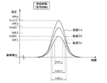
同図では、説明のため、ピーク値がそれぞれVref1、Vref2、Vref3(ただし、Vref1<Vref2<Vref3を満たす)となるリファレンス波形データが示されている。なお、気流の定常状態において得られる波形データは、これに限らず、単一波形であればどのようなピーク値を有しても構わない。また、ピーク値がそれぞれVref1、Vref2、Vref3となるリファレンス波形データは、粒径がD1、D2、D3(ただし、D1<D2<D3を満たす)の粒子2に対応する。 In the drawing, reference waveform data whose peak values are Vref1, Vref2, and Vref3 (where Vref1 <Vref2 <Vref3 is satisfied) is shown for explanation. The waveform data obtained in the steady state of the airflow is not limited to this, and may have any peak value as long as it is a single waveform. Further, the reference waveform data whose peak values are Vref1, Vref2, and Vref3 respectively correspond to particles 2 having particle diameters D1, D2, and D3 (providing that D1 <D2 <D3 is satisfied).
同図に示すように、粒径が大きい粒子2のリファレンス波形データほど、複数の閾値電圧Vth1〜Vth4の各々における時間幅が大きくなることがわかる。例えば、閾値電圧Vth1における各リファレンス波形データの時間幅に着目すると、粒径D1の時間幅Tref1、粒径D2の時間幅Tref2、及び、粒径D3の時間幅Tref3がTref1<Tref2<Tref3となる。 As shown in the figure, it can be seen that the reference waveform data of the particle 2 having a larger particle size has a larger time width in each of the plurality of threshold voltages Vth1 to Vth4. For example, focusing on the time width of each reference waveform data at the threshold voltage Vth1, the time width Tref1 of the particle size D1, the time width Tref2 of the particle size D2, and the time width Tref3 of the particle size D3 satisfy Tref1 <Tref2 <Tref3. .
本実施の形態では、演算部222は、取得したリファレンス波形データを示す情報を記憶部223に記憶させる。具体的には、演算部222は、当該情報として、取得したリファレンス波形データごとに、ピーク値、及び、複数の閾値Vth1〜Vth4の各々における時間幅を記憶部223に記憶させる。
In the present embodiment, the
なお、複数の閾値Vth1〜Vth4の個数及び間隔は特に限定されないが、例えば、粒子検出センサ1の測定対象の粒径分布に応じて適宜設定されてもかまわない。
The number and interval of the plurality of threshold values Vth1 to Vth4 are not particularly limited, but may be set as appropriate according to the particle size distribution of the measurement target of the
図7は、記憶部223に記憶されたリファレンス波形データを示す情報223aの一例を示す図である。
FIG. 7 is a diagram illustrating an example of
同図に示すように、記憶部223は、図6に示すリファレンス波形データごとに、ピーク値と、複数の閾値Vth1〜Vth4の各々における時間幅とを対応付けて記憶する。なお、記憶部223が記憶する情報はこれに限らず、例えば、リファレンス波形データそのものを記憶してもかまわない。
As shown in the figure, the
次に、測定波形取得処理(S20)及び質量濃度算出処理(S30)の詳細について、説明する。 Next, details of the measurement waveform acquisition process (S20) and the mass concentration calculation process (S30) will be described.
図8は、粒子検出センサ1による測定波形取得処理(S20)及び質量濃度算出処理(S30)の一例を示すフローチャートである。
FIG. 8 is a flowchart illustrating an example of a measurement waveform acquisition process (S20) and a mass concentration calculation process (S30) by the
まず、駆動制御部224が気流発生部15を間欠駆動する(S21)。
First, the
図9は、気流発生部15及び投光素子111の間欠駆動の一例を示すタイミングチャートである。図9には、ステップS21における、駆動制御部224が気流発生部15および投光素子111に出力する駆動信号、投光素子111の発光強度、及び粒子流路内の検知領域DAでの気流速度、の時間変化が示されている。駆動制御部224は出力する駆動信号(駆動電圧)は、オン状態(駆動電圧がハイレベル)のパルス信号の断続的な繰り返しとなっており、駆動制御部224による間欠駆動が実行されている。
FIG. 9 is a timing chart illustrating an example of intermittent driving of the
これに対し、投光素子111は、駆動信号のオン状態/オフ状態に連動して、発光/非発光を繰り返している。発光の立ち上がりおよび立ち下がりは、駆動信号の変化に即応している。
On the other hand, the
一方、気流発生部15は、駆動信号がオン状態に切り替わった時点で粒子流路への気流発生を開始し、オフ状態に切り替わった時点で粒子流路への気流発生を停止する。これにより、検知領域DAでの気流速度の立ち上がり波形は、駆動信号の立ち上がり波形に即応せず、所定の時間の経過後に一定速度へと収束する。つまり、駆動信号がオン状態である期間において、検知領域DAでの気流速度は、低速から高速へ徐々に変化する。
On the other hand, the
次に、気流発生部15が間欠駆動されている状態で、粒子検出センサ1が周辺空気を筐体13内の粒子流路に引き込むことにより、検知領域DAに粒子2を導入する(S22)。この処理は、上述のステップS12と同様である。
Next, in a state where the
このとき、受光素子121からアナログ信号処理部21へ、パルス状の波形を含む時系列の信号が出力される。ここで、受光素子121から出力される信号に含まれるパルス状の波形の時間幅は、リファレンス波形に含まれるパルス状の波形の時間幅に比べて変化する。
At this time, a time-series signal including a pulse waveform is output from the
次に、演算部222は、受光素子121からの出力を示す時系列のデジタルデータに含まれるパルス状の波形である波形データを取得する(S23)。
Next, the
図10は、気流発生部15が間欠駆動されている場合に得られる波形データの一例を示す波形図である。なお、同図には、気流発生部15が連続駆動(気流が定常状態)されている場合に同じ粒径の粒子2から得られる波形データも示されている。
FIG. 10 is a waveform diagram showing an example of waveform data obtained when the
同図に示すように、気流発生部15が間欠駆動されている(立ち上がり状態の)場合、連続駆動されている(定常状態の)場合に比べて、任意の閾値における時間幅が変化する。また、ピーク値が低下する場合もある。具体的には、間欠駆動状態(立ち上がり状態)の場合には、ピーク値がVαかつ時間幅がTαとなる連続駆動状態(定常状態)の場合に比べて、ピーク値がVβに低下し(ただし、Vα>Vβ)、閾値Vth1における時間幅がTαからTβ1とTβ2との範囲でブレることとなる(ただし、Tα>Tβ2>Tβ1)。なお、連続駆動状態の場合の時間幅と間欠駆動状態の場合の時間幅との大小関係は、時間幅を比較する閾値によって変わるため、連続駆動状態の場合の時間幅が間欠駆動状態の場合の時間幅より小さい場合もあり得る。
As shown in the figure, when the
次に、演算部222は、取得した複数の波形データのうち複数のピークを有する波形データを除外する(S31)。例えば、演算部222は、図3に示す波形W1〜W4に示すような波形データを取得した場合、以降の処理では、2つのピークを有する波形W4の波形データを除外して処理を行う。つまり、信号処理部20は、複数のピークを有する測定波形を除外して、質量濃度を算出することとなる。なお、以降、処理対象の波形データを測定波形データと記載する。
Next, the
次に、演算部222は、リファレンス波形データを記憶部223から読み出す(S32)。本実施の形態では、演算部222は、記憶部223に記憶されたリファレンス波形データを示す情報を取得する。
Next, the
その後、演算部222は、測定波形データとピーク値の近いリファレンス波形データがあるか否かを判断し(S33)、ピーク値の近いリファレンス波形データがある場合(S33でYes)、閾値の時間幅(波形幅)を取得する(S34)。具体的には、本実施の形態では、演算部222は、取得した複数の測定波形データの各々について、ピーク値の近いリファレンス波形データがあるか否かを判断する。また、リファレンス波形データとピーク値の近い測定波形データについては、複数の閾値Vth1〜Vth4の各々における時間幅を取得する。なお、ピーク値が近いとは、ピーク値が略一致することを指す。
Thereafter, the
一方、測定波形データとピーク値の近いリファレンス波形データがない場合(S33でNo)、上記の波形データ取得処理(S23)に戻って、以降の処理を繰り返す。 On the other hand, when there is no reference waveform data whose peak value is close to the measured waveform data (No in S33), the process returns to the waveform data acquisition process (S23) and the subsequent processes are repeated.
次に、演算部222は、測定波形データの時間幅とリファレンス波形データの時間幅とが一致するか否を判断し(S35)、これらの時間幅が一致する場合(S35でYes)、粒子流路の気流が定常状態で粒子が検出されたものであると判定して補正を非実施とする(S36)。つまり、当該場合、信号処理部20は、補正処理を行うことなく質量濃度を算出する。なお、質量濃度を算出する手法については、特に限定されてないが、例えば、所定時間内に取得した測定波形データのピークの個数により算出される個数濃度、及び、ピークの平均値に基づく平均質量等を用いて算出することができる。
Next, the
一方、演算部222は、これらの時間幅が一致しない場合(S35でNo)、粒子流路の気流が遷移状態で粒子が検出されたものと判定し、補正を実施する(S37)。つまり、当該場合、信号処理部20は、補正処理を行って質量濃度を算出する。つまり、演算部222は、測定波形データの時間幅とリファレンス波形データの時間幅との比較により、粒子流路の気流が遷移状態であるか定常状態であるかを推定し、遷移状態である場合には補正処理を行って質量濃度を算出する。なお、駆動制御部224が出力する駆動信号のデューティ比(オン状態の期間/1周期)は、大きいほど測定波形データとリファレンス波形データとが近似するので算出精度が向上するが、小さいほど消費電力の低減効果が大きくなる。
On the other hand, when these time widths do not match (No in S35), the
具体的には、本実施の形態では、信号処理部20は、ピーク値が略一致するリファレンス波形(ここではリファレンス波形データ)と測定波形(ここでは測定波形データ)とについて、複数の閾値Vth1〜Vth4それぞれにおける時間幅が略一致する場合、補正処理を行わない。一方、信号処理部20は、複数の閾値Vth1〜Vth4の少なくとも1つにおける時間幅が略一致しない場合、補正処理を行う。
Specifically, in the present embodiment, the
なお、補正処理を行うか否かの基準はこれに限らず、例えば、複数の閾値のうち半数以上の閾値で時間幅が略一致する場合に補正処理を行い、これ以外の場合に補正処理を行わなくてもかまわない。 Note that the criterion for determining whether or not to perform the correction process is not limited to this. For example, the correction process is performed when the time widths substantially match at half or more of the plurality of thresholds, and the correction process is performed in other cases. You don't have to.
信号処理部20は、補正処理において、次のような補正係数を用いて質量濃度を算出する。補正係数としては、気流発生部15が連続駆動されて粒子流路内の気流が定常状態となっている場合と気流発生部15が間欠駆動されて粒子流路内の気流が遷移状態となっている場合とで検知領域DAに同一粒径の粒子が導入された際の受光素子121からの出力を示す信号(ここでは、電圧信号)に含まれるパルス状の波形の時間幅またはピーク値の相対関係が挙げられる。例えば、信号処理部20は、上記定常状態のピーク値と上記遷移状態のピーク値との比を、補正係数として用いてもよい。
In the correction process, the
あるいは、補正係数として、例えば、上記定常状態の時間幅と上記遷移状態の時間幅との比であってもかまわない。また、補正係数は上記定常状態と上記遷移状態との何らかの比に限らず、差分であってもかまわない。また、補正係数は1つに限らず、複数定められていてもかまわない。つまり、例えば、信号処理部20は、上記遷移状態のピーク値に対応付けて補正係数が記憶されたデータベースを用いて補正処理を行ってもかまわない。
Alternatively, the correction coefficient may be, for example, a ratio between the time width of the steady state and the time width of the transition state. Further, the correction coefficient is not limited to any ratio between the steady state and the transition state, and may be a difference. Further, the correction coefficient is not limited to one, and a plurality of correction coefficients may be determined. That is, for example, the
信号処理部20は、補正処理として、例えば、上記定常状態であると仮定した場合に算出される質量濃度に対して上記の補正係数を乗算することにより、上記遷移状態の場合の質量濃度を算出する。なお、補正処理の手法はこれに限定されず、例えば、上記遷移状態のピーク値各々に補正係数を乗算することで、上記遷移状態の場合の質量濃度を算出してもかまわない。
For example, the
なお、補正係数は、記憶部23に記憶されていてもかまわないし、記憶部23とは別の記憶装置に記憶されていてもかまわない。あるいは、補正係数は、信号処理部20(本実施の形態では演算部222)が補正処理を行う際に実行されるコードに含まれていてもかまわない。
The correction coefficient may be stored in the storage unit 23, or may be stored in a storage device different from the storage unit 23. Alternatively, the correction coefficient may be included in the code executed when the signal processing unit 20 (the
このように、信号処理部20は、取得した測定波形(ここでは測定波形データ)とピーク値の近いリファレンス波形(ここではリファレンス波形データ)とについて、時間幅が測定波形に近い場合、補正処理を行うことなく質量濃度を算出し、当該時間幅が測定波形に近くない場合、補正処理を行って質量濃度を算出する。
As described above, the
なお、ステップS21〜ステップS23は上述の測定波形取得処理(S20)の一例であり、ステップS31〜ステップS37は上述の質量濃度算出処理(S30)の一例である。 Steps S21 to S23 are an example of the measurement waveform acquisition process (S20), and steps S31 to S37 are an example of the mass concentration calculation process (S30).
[3.適用例]
以上説明した粒子検出センサ1は、気体の質量濃度をモニタリングする(検知する)、持ち運びが可能な携帯型気体モニタに適用することができる。
[3. Application example]
The
図11は、本実施の形態に係る携帯型気体モニタ100の一例を示す機能ブロック図である。同図に示すように、携帯型気体モニタ100は、上述した粒子検出センサ1と、粒子検出センサ1に駆動電力を供給する電池3と、粒子検出センサ1で算出された質量濃度を表示する表示部4とを備える。携帯型気体モニタ100は、人が携帯することにより、また、移動体に設置することにより、閉鎖空間に限らず開放空間の気体の質量濃度をモニタリングすることが可能である。
FIG. 11 is a functional block diagram showing an example of the
本実施の形態に係る粒子検出センサ1によれば、気流発生部15の間欠駆動により低消費電力を実現できるので、商用電源を駆動電源とせず、例えば、容量が限られた電池を駆動電源とすることが可能となる。これにより、電池3および表示部4を備えることで、小型の携帯型気体モニタを実現できる。
According to the
[4.まとめ]
以上説明したように、粒子検出センサ1は、気体または液体である流体中(本実施の形態では気体中)に含まれる粒子を検出する粒子検出センサである。粒子検出センサ1は、検知領域DAに光を投光する投光素子111、及び、検知領域DAに位置する粒子2によって散乱された光を受光する受光素子121と、検知領域DAに気流を発生させる気流発生部15と、気流発生部15を間欠駆動する駆動制御部224とを備える。また、粒子検出センサ1は、受光素子121からの出力を示す時系列の信号を信号処理することにより、流体中に含まれる粒子の質量濃度を算出する信号処理部20を備える。ここで、信号処理部20は、検知領域DAにおける気流が定常状態となっている場合の基準となるリファレンス波形を取得し、駆動制御部224が気流発生部15を間欠駆動している状態で時系列の信号に対応した測定波形を取得し、リファレンス波形と測定波形とについて、波形が略一致する場合、補正処理を行うことなく質量濃度を算出し、当該波形が略一致しない場合、補正処理を行って質量濃度を算出する。
[4. Summary]
As described above, the
より具体的には、信号処理部20は、定常状態となっている場合の基準となるパルス状のリファレンス波形を取得し、駆動制御部224が間欠駆動している状態で、時系列の信号に含まれるパルス状の測定波形を取得し、ピーク値が略一致するリファレンス波形と測定波形とについて、時間幅が略一致する場合、補正処理を行うことなく質量濃度を算出し、当該時間幅が略一致しない場合、上記補正処理を行って質量濃度を算出する。
More specifically, the
ここで、低消費電力化を目的として気流発生部15を間欠駆動すると、連続駆動の場合に比べて、検知領域DAにおける気流速度が変動することで上記の時系列の信号が変化する。このため、測定波形のピーク値及び時間幅が上記連続駆動の場合に比べて変化する。よって、粒子検出センサ1は、ピーク値が略一致するリファレンス波形と測定波形とについて時間幅が略一致しない場合、検知領域DAにおける気流速度が遷移(立ち上がり)状態にあるとみなして補正処理を行う。気流発生部15の上記間欠駆動および信号処理部20での上記補正処理により、検出精度の劣化を低減しつつ、低消費電力化及び質量濃度算出の高速化を実現することが可能となる。
Here, when the
また、粒子検出センサ1によれば、気流発生部15の間欠駆動により低消費電力を実現できるので、駆動用電源として商用電源を必要とせず、例えば、電池を駆動用電源とすることが可能となる。このため、粒子検出センサ1は、持ち運び可能な小型の粒子検出センサとして好適となり得る。
Further, according to the
また、駆動制御部224は、気流発生部15の間欠駆動と同期させて、気流発生部15の動作時に投光素子111を発光させ、気流発生部15の非動作時に投光素子111を消光させる。これにより、投光素子111を発光させるための電力を低減できるので、粒子検出センサ1の消費電力を、より低減できる。
Further, the
また、信号処理部20は、複数のピークを有するパルス状の測定波形を除外して、質量濃度を算出する。
Further, the
ここで、複数のピークを有するパルス状の測定波形は、検知領域DAに位置する複数の粒子2に対応する複数の波形の合成波である。このため、複数のピークを有するパルス状の測定波形は、1つの粒子の波形に比べて時間幅が大きくなってしまい、検出精度の劣化の要因となり得る。よって、複数のピークを有する測定波形を除外して質量濃度を算出することにより、検出精度の向上が図られる。 Here, the pulse-like measurement waveform having a plurality of peaks is a combined wave of a plurality of waveforms corresponding to the plurality of particles 2 located in the detection area DA. For this reason, the pulse-shaped measurement waveform having a plurality of peaks has a longer time width than the waveform of one particle, which may cause deterioration in detection accuracy. Therefore, the detection accuracy can be improved by calculating the mass concentration excluding the measurement waveform having a plurality of peaks.
また、信号処理部20は、ピーク値が略一致するリファレンス波形と測定波形とについて、複数の閾値それぞれにおける時間幅が略一致する場合、補正処理を行わず、複数の閾値の少なくとも1つにおける時間幅が略一致しない場合、補正処理を行う。
Further, the
ここで、ピーク値が略一致し、かつ、互いに波形形状が異なるリファレンス波形と測定波形とについて、1つの閾値のみで時間幅を比べると、これらの時間幅が略一致してしまう場合がある。この場合、補正処理を行うことなく質量濃度を算出してしまい、検出精度が劣化し得る。よって、ピーク値が略一致するリファレンス波形と測定波形とについて、複数の閾値の少なくとも1つにおける時間幅が略一致しない場合に補正処理を行うことにより、検出精度の劣化を一層低減することができる。 Here, when the time widths of the reference waveform and the measurement waveform having substantially the same peak value and different waveform shapes are compared with only one threshold, the time widths may be substantially the same. In this case, the mass concentration is calculated without performing the correction process, and the detection accuracy may be deteriorated. Therefore, for the reference waveform and the measurement waveform having substantially the same peak value, when the time width of at least one of the plurality of threshold values does not substantially match, the detection accuracy can be further reduced by performing the correction process. .
また、信号処理部20は、補正処理において、気流発生部15が連続駆動されて気流が定常状態となっている場合と気流発生部15が間欠駆動されている場合とで、検知領域DAに同一粒径の粒子が導入された際の時系列の信号に含まれるパルス状の波形の時間幅またはピーク値の相対関係を用いて、質量濃度を算出する。
The
このような相対関係を用いることにより、気流発生部15が間欠駆動されている場合の質量濃度を補正して、検出精度の劣化を低減することができる。
By using such a relative relationship, it is possible to correct the mass concentration when the
また、気流発生部15は、ファン、マイクロポンプ、または直流電動モータを含む。
The
これにより、粒子流路の気流の立ち上がりを速くすることが可能となる。このため、気流発生部15の間欠駆動におけるオン状態の期間及び間欠駆動の周期を短縮できるので、低消費電力化及び質量濃度算出の高速化を実現することが可能となる。
This makes it possible to speed up the rise of the airflow in the particle flow path. For this reason, since the period of the ON state and the period of intermittent drive in the intermittent drive of the
また、携帯型気体モニタ100は、上述の粒子検出センサ1と、粒子検出センサ1を駆動するための電池3と、粒子検出センサ1で算出された質量濃度を表示する表示部4とを備える。
The
これにより、携帯型気体モニタ100は、気流発生部15の間欠駆動により低消費電力を実現できるので、商用電源を駆動用電源とせず、例えば、容量が限られた電池3を駆動用電源とすることが可能となる。これにより、持ち運び可能な小型の気体モニタを実現できる。
As a result, the
また、粒子検出方法は、検知領域DAに光を投光する投光素子111、検知領域DAに位置する粒子2によって散乱された光を受光する受光素子121、及び、検知領域DAに気流を発生させる気流発生部15を有する粒子検出センサ1を用いて、流体中に含まれる粒子を検出する粒子検出方法である。粒子検出方法は、検知領域DAにおける気流が定常状態となっている場合の基準となるリファレンス波形を取得するステップ(S10)と、気流発生部15を間欠駆動している状態で受光素子121からの出力を示す時系列の信号に対応した測定波形を取得するステップ(S20)とを含む。また、粒子検出方法は、リファレンス波形と測定波形とについて、波形が略一致する場合、補正処理を行うことなく流体中に含まれる粒子の質量濃度を算出し、当該波形が略一致しない場合、補正処理を行って質量濃度を算出するステップ(S30)を含む。
The particle detection method includes a
このように、粒子検出方法は、リファレンス波形と気流発生部15を間欠駆動している状態での測定波形とについて波形(時間幅)が略一致しない場合、補正処理を行って質量濃度を算出する。これにより、検出精度の劣化を低減しつつ、低消費電力化及び質量濃度算出の高速化を実現することが可能となる。
Thus, in the particle detection method, when the waveform (time width) does not substantially match the reference waveform and the measurement waveform in the state where the
(その他の実施の形態)
以上、本発明について実施の形態及び変形例に基づいて説明したが、本発明は、上記の実施の形態及び変形例に限定されるものではない。
(Other embodiments)
As described above, the present invention has been described based on the embodiment and the modification. However, the present invention is not limited to the above embodiment and the modification.
例えば、上記実施の形態では、信号処理部20が、受光素子121からの受光強度と測定時間とで表された時系列の測定波形とリファレンス波形とを比較して、補正処理および質量濃度の算出を実行したが、信号処理部20の処理はこれに限られない。
For example, in the above-described embodiment, the
信号処理部20は、受光素子121からの受光強度と当該受光強度に対応した周波数成分とで表された測定波形とリファレンス波形とを比較して、補正処理および質量濃度の算出を実行してもよい。具体的には、信号処理部20は、気流が定常状態である場合の基準となる周波数成分と周波数成分毎の強度との関係を示すリファレンス情報を取得する。一方、駆動制御部224が気流発生部15を間欠駆動している場合の受光素子121からの出力を示す時系列の信号を周波数分析することにより、当該信号に含まれる周波数成分と周波数成分毎の強度との関係を示す測定情報を取得する。上記リファレンス情報及び上記測定情報は、例えば、それぞれ、受光素子からの出力を示す時系列の信号をフーリエ変換したリファレンス波形及び測定波形である。そして、演算部222は、上記リファレンス情報と上記測定情報とについて、周波数成分毎の強度の相対関係が略一定の場合、補正処理を行うことなく質量濃度を算出し、当該相対関係が略一定でない場合、上記補正処理を行って質量濃度を算出する。
The
つまり、信号処理部20は、検知領域DAにおける気流が定常状態となっている場合の基準となるリファレンス波形を取得し、駆動制御部224が気流発生部15を間欠駆動している場合の時系列の信号に対応した測定波形を取得し、リファレンス波形と測定波形とについて、波形が略一致する場合、補正処理を行うことなく質量濃度を算出し、当該波形が略一致しない場合、補正処理を行って質量濃度を算出する。
That is, the
低消費電力化を目的として気流発生部15を間欠駆動すると、連続駆動の場合に比べて、検知領域DAにおける気流速度が変動することで上記の時系列の信号が変化する。このため、連続駆動の場合に比べて、当該信号に含まれる周波数成分及び周波数成分ごとの強度が変化することとなる。よって、上記リファレンス情報と上記測定情報とについて、周波数成分毎の強度の相対関係が略一定でない場合、検知領域DAにおける気流が遷移(立ち上がり)状態にあるとみなして補正処理を行う。これにより、検出精度の劣化を低減しつつ、低消費電力化及び質量濃度算出の高速化を実現することが可能となる。
When the
また、例えば、粒子検出センサ1は、IV変換部211、増幅部212、AD変換部221のうち少なくとも1つを備えていなくてもよく、例えば、粒子検出センサ1がAD変換部221を備えず、演算部222が増幅部212から出力された電圧信号を用いて粒子2の粒径を演算してもよい。ただし、以下の観点から、粒子検出センサ1はAD変換部221を備えることが好ましい。
For example, the
すなわち、粒子検出センサ1がAD変換部221を備えない場合、電圧信号のピークをアナログで算出する構成としては、例えば、ピークホールド回路、及び、複数の閾値と比較するための複数のコンパレータを用いる構成が考えられる。しかしながら、このような構成では、ピークホールド回路内のコンデンサの充放電に時間を要することにより、電圧信号のピークを高速に検出することが困難である。さらに、アナログ回路構成として、複数のコンパレータを備えることが必要である。
That is, when the
これに対して、粒子検出センサ1が汎用MPU22に予め組み込まれたAD変換モジュールであるAD変換部221を備える場合、上記ピークホールド回路を用いる場合よりも電圧信号のピークを高速に検出することができるため、粒子の粒径を高速に演算できる。さらに、アナログ回路構成として複数のコンパレータを備える必要がないので、アナログ回路構成を簡素化及び低コスト化できる。
On the other hand, when the
また、上記説明において、粒子を含む媒体は、気体(空気)としたが、気体以外の媒体(水等の液体)であってもよい。つまり、粒子検出センサ1は、気体または液体である流体中に含まれる粒子を検出する。
In the above description, the medium containing particles is gas (air), but it may be a medium other than gas (liquid such as water). That is, the
また、上記説明において、汎用MPU22内の各構成要素は、専用のハードウェアで構成されるか、各構成要素に適したソフトウェアプログラムを実行することによって実現されてもよい。各構成要素は、CPUまたはプロセッサなどのプログラム実行部が、ハードディスクまたは半導体メモリなどの記録媒体に記録されたソフトウェアプログラムを読み出して実行することによって実現されてもよい。
In the above description, each component in the general-
また、汎用MPU22を構成する構成要素(機能)の一部または全ては、粒子検出センサ1を備える各種機器(例えば、携帯型気体モニタ100)に搭載されたマイクロプロセッサ、ROM、RAM等の一部として実現されていてもかまわない。
In addition, some or all of the constituent elements (functions) constituting the general-
また、本発明は、このような粒子検出センサ1として実現することができるだけでなく、粒子検出センサ1が行うステップ(処理)を含む方法として実現できる。
Further, the present invention can be realized not only as such a
例えば、それらのステップは、コンピュータ(コンピュータシステム)によって実行されてもよい。そして、本発明は、それらの方法に含まれるステップを、コンピュータに実行させるためのプログラムとして実現できる。さらに、本発明は、そのプログラムを記録したCD−ROM等である非一時的なコンピュータ読み取り可能な記録媒体として実現できる。 For example, these steps may be performed by a computer (computer system). The present invention can be realized as a program for causing a computer to execute the steps included in these methods. Furthermore, the present invention can be realized as a non-transitory computer-readable recording medium such as a CD-ROM on which the program is recorded.
例えば、本発明が、プログラム(ソフトウェア)で実現される場合には、コンピュータのCPU、メモリおよび入出力回路等のハードウェア資源を利用してプログラムが実行されることによって、各ステップが実行される。つまり、CPUがデータをメモリまたは入出力回路等から取得して演算したり、演算結果をメモリまたは入出力回路等に出力したりすることによって、各ステップが実行される。 For example, when the present invention is realized by a program (software), each step is executed by executing the program using hardware resources such as a CPU, a memory, and an input / output circuit of a computer. . That is, each step is executed by the CPU obtaining data from a memory or an input / output circuit or the like, and outputting the calculation result to the memory or the input / output circuit.
その他、各実施の形態に対して当業者が思いつく各種変形を施して得られる形態、または、本発明の趣旨を逸脱しない範囲で各実施の形態における構成要素および機能を任意に組み合わせることで実現される形態も本発明に含まれる。 In addition, it is realized by variously conceiving various modifications conceived by those skilled in the art to each embodiment, or by arbitrarily combining the components and functions in each embodiment without departing from the spirit of the present invention. This form is also included in the present invention.
1 粒子検出センサ
2 粒子
3 電池
4 表示部
15 気流発生部(流速発生部)
20 信号処理部
100 携帯型気体モニタ
111 投光素子
121 受光素子
224 駆動制御部
DESCRIPTION OF
20
Claims (9)
検知領域に光を投光する投光素子、及び、前記検知領域に位置する前記粒子によって散乱された光を受光する受光素子と、
前記検知領域に前記気体または前記液体の流れを発生させる流速発生部と、
前記流速発生部を間欠駆動する駆動制御部と、
前記受光素子からの出力を示す時系列の信号を信号処理することにより、前記流体中に含まれる前記粒子の質量濃度を算出する信号処理部とを備え、
前記信号処理部は、
前記検知領域における前記気体または前記液体の流れが定常状態となっている場合の基準となるリファレンス波形を取得し、
前記駆動制御部が前記流速発生部を間欠駆動している場合の前記時系列の信号に対応した測定波形を取得し、
前記リファレンス波形と前記測定波形とについて、波形が略一致する場合、補正処理を行うことなく前記質量濃度を算出し、当該波形が略一致しない場合、前記補正処理を行って前記質量濃度を算出する
粒子検出センサ。 A particle detection sensor for detecting particles contained in a fluid that is a gas or a liquid,
A light projecting element that projects light to the detection region, and a light receiving device that receives light scattered by the particles located in the detection region;
A flow rate generator for generating a flow of the gas or the liquid in the detection region;
A drive controller that intermittently drives the flow velocity generator;
A signal processing unit that calculates a mass concentration of the particles contained in the fluid by processing a time-series signal indicating an output from the light receiving element;
The signal processing unit
Obtain a reference waveform as a reference when the flow of the gas or the liquid in the detection region is in a steady state,
Obtaining a measurement waveform corresponding to the time-series signal when the drive controller is intermittently driving the flow velocity generator;
For the reference waveform and the measurement waveform, when the waveforms are substantially the same, the mass concentration is calculated without performing a correction process. When the waveforms are not substantially the same, the correction process is performed to calculate the mass concentration. Particle detection sensor.
前記流速発生部の間欠駆動と同期させて、前記流速発生部の動作時に前記投光素子を発光させ、前記流速発生部の非動作時に前記投光素子を消光させる
請求項1に記載の粒子検出センサ。 The drive control unit
The particle detection according to claim 1, wherein the light projecting element is caused to emit light when the flow speed generating unit is operated, and the light projecting element is quenched when the flow rate generating unit is not operated, in synchronization with the intermittent driving of the flow rate generating unit. Sensor.
前記定常状態となっている場合の基準となるパルス状の前記リファレンス波形を取得し、
前記駆動制御部が前記間欠駆動している場合の前記時系列の信号に含まれるパルス状の前記測定波形を取得し、
ピーク値が略一致する前記リファレンス波形と前記測定波形とについて、時間幅が略一致する場合、補正処理を行うことなく前記質量濃度を算出し、当該時間幅が略一致しない場合、前記補正処理を行って前記質量濃度を算出する
請求項1または2に記載の粒子検出センサ。 The signal processing unit
Obtain the pulse-shaped reference waveform as a reference when the steady state,
Obtaining the pulsed measurement waveform included in the time-series signal when the drive control unit is intermittently driven;
When the time widths of the reference waveform and the measurement waveform having substantially the same peak value are substantially the same, the mass concentration is calculated without performing the correction process, and when the time widths are not substantially the same, the correction process is performed. The particle detection sensor according to claim 1, wherein the mass concentration is calculated by performing.
請求項3に記載の粒子検出センサ。 The particle detection sensor according to claim 3, wherein the signal processing unit calculates the mass concentration by excluding the pulse-shaped measurement waveform having a plurality of peaks.
請求項3または4に記載の粒子検出センサ。 The signal processing unit does not perform the correction process and does not perform the correction process when the time widths of each of the plurality of threshold values substantially match for the reference waveform and the measurement waveform whose peak values substantially match, and at least one of the plurality of threshold values The particle detection sensor according to claim 3, wherein the correction process is performed when the time widths of the two do not substantially match.
請求項3〜5のいずれか1項に記載の粒子検出センサ。 In the correction process, the signal processing unit is the same as the detection region when the flow rate generation unit is continuously driven and the flow is in the steady state and when the flow rate generation unit is intermittently driven. The mass concentration is calculated using a relative relationship between a time width or a peak value of a pulse-like waveform included in the time-series signal when a particle having a particle size is introduced. The particle detection sensor according to Item.
請求項1〜6のいずれか1項に記載の粒子検出センサ。 The particle detection sensor according to claim 1, wherein the flow velocity generation unit includes a fan, a micro pump, or a DC electric motor.
前記粒子検出センサを駆動するための電池と、
前記粒子検出センサで算出された前記質量濃度を表示する表示部とを備える
携帯型気体モニタ。 The particle detection sensor according to any one of claims 1 to 7,
A battery for driving the particle detection sensor;
A portable gas monitor comprising: a display unit that displays the mass concentration calculated by the particle detection sensor.
前記検知領域における前記気体または前記液体の流れが定常状態となっている場合の基準となるリファレンス波形を取得するステップと、
前記流速発生部を間欠駆動している状態で、前記受光素子からの出力を示す時系列の信号に対応した測定波形を取得するステップと、
前記リファレンス波形と前記測定波形とについて、波形が略一致する場合、補正処理を行うことなく前記流体中に含まれる前記粒子の質量濃度を算出し、当該波形が略一致しない場合、前記補正処理を行って前記質量濃度を算出するステップとを含む
粒子検出方法。 Particle detection having a light projecting element that projects light onto a detection area, a light receiving element that receives light scattered by particles located in the detection area, and a flow velocity generator that generates a flow of gas or liquid in the detection area A particle detection method for detecting the particles contained in a fluid that is a gas or a liquid using a sensor,
Obtaining a reference waveform as a reference when the flow of the gas or the liquid in the detection region is in a steady state;
Obtaining a measurement waveform corresponding to a time-series signal indicating an output from the light receiving element in a state where the flow velocity generation unit is intermittently driven;
For the reference waveform and the measurement waveform, when the waveforms are substantially the same, the mass concentration of the particles contained in the fluid is calculated without performing the correction process, and when the waveforms are not substantially the same, the correction process is performed. And calculating the mass concentration. A particle detection method.
Priority Applications (1)
| Application Number | Priority Date | Filing Date | Title |
|---|---|---|---|
| JP2016023170A JP2017142142A (en) | 2016-02-09 | 2016-02-09 | Particle detection sensor, portable gas monitor, and particle detection method |
Applications Claiming Priority (1)
| Application Number | Priority Date | Filing Date | Title |
|---|---|---|---|
| JP2016023170A JP2017142142A (en) | 2016-02-09 | 2016-02-09 | Particle detection sensor, portable gas monitor, and particle detection method |
Publications (1)
| Publication Number | Publication Date |
|---|---|
| JP2017142142A true JP2017142142A (en) | 2017-08-17 |
Family
ID=59627199
Family Applications (1)
| Application Number | Title | Priority Date | Filing Date |
|---|---|---|---|
| JP2016023170A Pending JP2017142142A (en) | 2016-02-09 | 2016-02-09 | Particle detection sensor, portable gas monitor, and particle detection method |
Country Status (1)
| Country | Link |
|---|---|
| JP (1) | JP2017142142A (en) |
Cited By (3)
| Publication number | Priority date | Publication date | Assignee | Title |
|---|---|---|---|---|
| CN109342285A (en) * | 2018-11-27 | 2019-02-15 | 广州勒夫迈智能科技有限公司 | A kind of particle detection technique of infrared emission |
| JP2019045197A (en) * | 2017-08-30 | 2019-03-22 | パナソニックIpマネジメント株式会社 | Particle detection sensor and particle detection method |
| CN109342285B (en) * | 2018-11-27 | 2024-04-30 | 广州勒夫迈智能科技有限公司 | Infrared correlation particle detection method |
-
2016
- 2016-02-09 JP JP2016023170A patent/JP2017142142A/en active Pending
Cited By (3)
| Publication number | Priority date | Publication date | Assignee | Title |
|---|---|---|---|---|
| JP2019045197A (en) * | 2017-08-30 | 2019-03-22 | パナソニックIpマネジメント株式会社 | Particle detection sensor and particle detection method |
| CN109342285A (en) * | 2018-11-27 | 2019-02-15 | 广州勒夫迈智能科技有限公司 | A kind of particle detection technique of infrared emission |
| CN109342285B (en) * | 2018-11-27 | 2024-04-30 | 广州勒夫迈智能科技有限公司 | Infrared correlation particle detection method |
Similar Documents
| Publication | Publication Date | Title |
|---|---|---|
| KR101913973B1 (en) | Particle detection sensor | |
| JP2020537148A (en) | Calibration of particle counter components | |
| JP2016128795A (en) | Particle measurement device, air cleaning machine, and particle measurement method | |
| CN108291862B (en) | Particle detection sensor, dust sensor, smoke sensor, air conditioner, and particle detection method | |
| CN106253853B (en) | Signal processing device and noise intensity determination method | |
| JP2017173229A (en) | Particle detection sensor, dust sensor, smoke sensor, air conditioner and particle detection method | |
| JP2018044852A (en) | Laser emission device, control method and program | |
| JP2015210189A (en) | Particle measuring apparatus | |
| JP6233711B2 (en) | Particle measuring device | |
| US11719615B2 (en) | Particle detection device | |
| JP2017142142A (en) | Particle detection sensor, portable gas monitor, and particle detection method | |
| JP2018044853A (en) | Laser emission device, control method and program | |
| JP2015210188A (en) | Particle measuring apparatus | |
| JP2016109629A (en) | Particle measuring apparatus, air cleaner, and particle measuring method | |
| JP2017142141A (en) | Particle detection sensor, mobile entity onboard gas monitor, and particle detection method | |
| JP6830262B2 (en) | Particle detection sensor, dust sensor, smoke detector, and air conditioner | |
| JP2016095171A (en) | Signal output device, particle measuring apparatus, and storage method for signal output device | |
| JP2019158723A (en) | Particle sensor, electronic apparatus equipped therewith, and particle information detection method | |
| JP2017142139A (en) | Particle detection sensor, mobile entity onboard gas monitor, and particle detection method | |
| JP2012173176A (en) | Signal processor and laser measurement device | |
| JP6571709B2 (en) | Particle measuring apparatus and air purifier | |
| CN207457013U (en) | A kind of optical particle sensors of double working modes | |
| US10024779B2 (en) | Sample measuring apparatus and sample measuring method | |
| JP5907498B1 (en) | Particle detection sensor | |
| US20230014629A1 (en) | Methods for determining photodetector gain-voltage using optical signals |