JP2017140744A - Screen printer - Google Patents

Screen printer Download PDF

Info

Publication number
JP2017140744A
JP2017140744A JP2016022827A JP2016022827A JP2017140744A JP 2017140744 A JP2017140744 A JP 2017140744A JP 2016022827 A JP2016022827 A JP 2016022827A JP 2016022827 A JP2016022827 A JP 2016022827A JP 2017140744 A JP2017140744 A JP 2017140744A
Authority
JP
Japan
Prior art keywords
frame
printing
screen
printing machine
unit
Prior art date
Legal status (The legal status is an assumption and is not a legal conclusion. Google has not performed a legal analysis and makes no representation as to the accuracy of the status listed.)
Granted
Application number
JP2016022827A
Other languages
Japanese (ja)
Other versions
JP6717608B2 (en
Inventor
豊 井戸
Yutaka Ido
豊 井戸
Current Assignee (The listed assignees may be inaccurate. Google has not performed a legal analysis and makes no representation or warranty as to the accuracy of the list.)
Sakurai Graphic Systems Corp
Original Assignee
Sakurai Graphic Systems Corp
Priority date (The priority date is an assumption and is not a legal conclusion. Google has not performed a legal analysis and makes no representation as to the accuracy of the date listed.)
Filing date
Publication date
Application filed by Sakurai Graphic Systems Corp filed Critical Sakurai Graphic Systems Corp
Priority to JP2016022827A priority Critical patent/JP6717608B2/en
Publication of JP2017140744A publication Critical patent/JP2017140744A/en
Application granted granted Critical
Publication of JP6717608B2 publication Critical patent/JP6717608B2/en
Active legal-status Critical Current
Anticipated expiration legal-status Critical

Links

Images

Abstract

PROBLEM TO BE SOLVED: To provide a screen printer capable of enhancing a space efficiency in a printer frame.SOLUTION: A screen printer comprises: a support frame 26 for supporting a screen frame 28, which reciprocates along a transfer direction of a print sheet with regard to a print barrel below. Racks 31 are disposed on both sides of the support frame 26, while pinions 33 are disposed on output shafts of drive motors disposed on both sides of the printer frame, so that the pinions 33 are engaged with the respective racks 31. Thereby, the drive motor drives the support frame 26 to reciprocate.SELECTED DRAWING: Figure 7

Description

本発明は、印刷胴に対してスクリーン枠を移動させるようにしたスクリーン印刷機に関するものである。   The present invention relates to a screen printing machine in which a screen frame is moved with respect to a printing cylinder.

この種のスクリーン印刷機が特許文献1に開示されている。この特許文献1のスクリーン印刷機においては、駆動モータが印刷機フレーム内に設置されている。その駆動モータの回転がベルトなどの伝達系を介して軸に伝達される。この軸はスクリーン印刷機の版枠,すなわちスクリーン枠の移動方向と直交する方向に延在し、その両端と版枠を支持する搬送フレームの両側との間にベルトなどの伝達系が設けられている。従って、駆動モータの回転が前記軸に伝達され、その軸の回転が搬送フレームの両側の伝達系に伝達されて、搬送フレームが版枠を支持した状態で往復動される。   This type of screen printing machine is disclosed in Patent Document 1. In the screen printing machine of Patent Document 1, a drive motor is installed in the printing machine frame. The rotation of the drive motor is transmitted to the shaft through a transmission system such as a belt. This shaft extends in the direction perpendicular to the moving direction of the screen frame of the screen printing machine, that is, the screen frame, and a transmission system such as a belt is provided between both ends of the plate frame and both sides of the transport frame that supports the plate frame. Yes. Accordingly, the rotation of the drive motor is transmitted to the shaft, the rotation of the shaft is transmitted to the transmission systems on both sides of the transport frame, and the transport frame is reciprocated while supporting the plate frame.

特開平9−29932号公報JP-A-9-29932

特許文献1のスクリーン印刷機においては、駆動モータが印刷機フレーム内に位置しているため、駆動モータと軸との間の伝達系も印刷機フレーム内に位置することになり、このため、印刷機フレーム内の空間が狭くなり、その空間のスペース効率が悪くなる。また、印刷機フレームの上部において、前記軸が搬送フレームの移動方向と直交した状態で横たわるようにして延在されている。このため、この軸が搬送フレームの移動を阻害しないように、同軸を搬送フレームの移動範囲外の位置に設置する必要があって、印刷機の設計上の制約要因となった。さらに、駆動モータと軸との間に伝達系が設けられているため、部品点数が多くなって構成が複雑になる。   In the screen printing machine of Patent Document 1, since the drive motor is located in the printing machine frame, the transmission system between the drive motor and the shaft is also located in the printing machine frame. The space in the machine frame becomes narrower, and the space efficiency of the space becomes worse. In addition, the shaft extends in an upper part of the printing press frame so as to lie in a state orthogonal to the moving direction of the transport frame. For this reason, it is necessary to install the coaxial at a position outside the moving range of the transport frame so that the shaft does not hinder the movement of the transport frame, which is a limiting factor in designing the printing press. Furthermore, since the transmission system is provided between the drive motor and the shaft, the number of parts increases and the configuration becomes complicated.

この発明は、このような従来の技術に存在する問題点に着目してなされたものであって、その目的は、印刷機フレーム内のスペース効率を向上できるスクリーン印刷機を提供することにある。   The present invention has been made paying attention to such problems existing in the prior art, and an object thereof is to provide a screen printing machine capable of improving the space efficiency in the printing machine frame.

上記の目的を達成するために、本発明においては、スクリーン枠が支持される支持枠をその下部の印刷胴に対して印刷シートの搬送方向に沿って往復動されるスクリーン印刷機において、前記スクリーン枠の両側にラックが設けられ、フレームの両側に設けられた駆動モータの出力軸にピニオンが設けられるとともに、そのピニオンが前記ラックに噛合されたことを特徴とする。   In order to achieve the above object, in the present invention, in the screen printing machine in which the support frame on which the screen frame is supported is reciprocated along the print sheet conveyance direction with respect to the lower printing cylinder, the screen Racks are provided on both sides of the frame, pinions are provided on output shafts of drive motors provided on both sides of the frame, and the pinions are engaged with the racks.

以上の構成においては、駆動モータを印刷機フレームの外側に配置することができる。従って、印刷機フレームの内部空間のスペース効率を向上させることができる。また、モータと支持枠との間には、ラックとピニオンとを設ければよく、部品点数が少なく、構成が簡単である。   In the above configuration, the drive motor can be disposed outside the printing machine frame. Therefore, the space efficiency of the internal space of the printing press frame can be improved. In addition, a rack and a pinion may be provided between the motor and the support frame, and the number of parts is small and the configuration is simple.

本発明においては、印刷機フレームの内部空間のスペース効率を向上させることができる効果がある。   The present invention has an effect of improving the space efficiency of the internal space of the printing press frame.

内部構造を省略して示すスクリーン印刷機の斜視図。FIG. 3 is a perspective view of a screen printing machine with an internal structure omitted. スクリーン印刷機の側面図。A side view of a screen printing machine. 印刷胴を示す正面図。The front view which shows a printing cylinder. スクリーン印刷機の背面図。The rear view of a screen printing machine. スキージ・ドクターユニットを示す断面図。Sectional drawing which shows a squeegee doctor unit. スクリーン枠の関連構成を示す平面図。The top view which shows the related structure of a screen frame. 支持枠を示す簡略平面図。The simplified top view which shows a support frame. 支持枠がホームポジションに配置された状態における支持枠の関連構成を示す一部正面図。The partial front view which shows the related structure of the support frame in the state in which the support frame was arrange | positioned in the home position. 支持枠が中間位置に配置された状態における支持枠の関連構成を示す一部正面図。The partial front view which shows the related structure of the support frame in the state by which the support frame was arrange | positioned in the intermediate position. 支持枠が移動端位置に配置された状態における支持枠の関連構成を示す一部正面図。The partial front view which shows the related structure of the support frame in the state by which the support frame is arrange | positioned in the movement end position. 搬送ユニットを示す平面図。The top view which shows a conveyance unit. 搬送ユニットが上方位置に配置された状態を示す断面図。Sectional drawing which shows the state by which the conveyance unit was arrange | positioned in the upper position. 搬送ユニットが垂下位置に配置された状態を示す断面図。Sectional drawing which shows the state by which the conveyance unit is arrange | positioned in the drooping position. 搬送ユニットを示す簡略正面図。The simplified front view which shows a conveyance unit. 保持ユニットを示す簡略断面図。The simplified sectional view showing a holding unit. カバーユニット及び吸気ユニットを示す平面図。The top view which shows a cover unit and an intake unit. カバーユニット及び吸気ユニットを示す一部側面図。The partial side view which shows a cover unit and an intake unit. カバーユニット及び吸気ユニットを示す一部正面図。The partial front view which shows a cover unit and an intake unit. 吸気ユニットを示す一部背面図。The partial rear view which shows an intake unit. カバーユニットの閉鎖状態を示す簡略正面図。The simplified front view which shows the closed state of a cover unit. スクリーン枠の移動領域を開放した状態を示すカバーユニットの簡略正面図。The simplified front view of the cover unit which shows the state which open | released the movement area | region of the screen frame. 印刷機フレームの上面を開放した状態を示すカバーユニットの簡略正面図。The simplified front view of the cover unit which shows the state which open | released the upper surface of the printing machine flame | frame.

(実施形態)
以下、本発明を具体化した実施形態を図面に基づいて説明する。
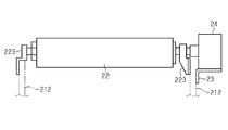
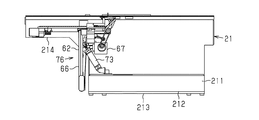
図1及び図2に示すように、印刷機フレーム21は、フレーム底壁部211と、その両側のフレーム側壁部212とを備えている。なお、図1においては、印刷機の内部構造を省略して描いてある。その両フレーム側壁部212の上部間には、図3に示すように、軸受223を介して印刷胴22が回転可能に支持されている。一方のフレーム側壁部212の外側面にはブラケット23を介してサーボモータよりなる回転駆動モータ24が支持され、そのモータ軸が前記印刷胴22の中心軸に直結されている。そして、前記回転駆動モータ24の駆動によって印刷胴22が一方向に間欠回転されて、この間欠回転により、図7に示す印刷シートαが1枚ずつ間欠搬送される。
(Embodiment)
DESCRIPTION OF THE PREFERRED EMBODIMENTS Embodiments embodying the present invention will be described below with reference to the drawings.
As shown in FIGS. 1 and 2, the printing machine frame 21 includes a frame bottom wall portion 211 and frame side wall portions 212 on both sides thereof. In FIG. 1, the internal structure of the printing press is omitted. As shown in FIG. 3, the printing cylinder 22 is rotatably supported between the upper portions of the frame side wall portions 212 via bearings 223. A rotation drive motor 24 composed of a servo motor is supported on the outer surface of one frame side wall 212 via a bracket 23, and the motor shaft is directly connected to the central axis of the printing cylinder 22. Then, the printing cylinder 22 is intermittently rotated in one direction by driving of the rotation driving motor 24, and the printing sheet α shown in FIG. 7 is intermittently conveyed one by one by this intermittent rotation.

図1及び図4に示すように、前記フレーム側壁部212は、本体213と、その本体213の上端から前方へ突出したアーム部214とを備えている。図5及び図6に示すように、本体213からアーム部214にかけて両フレーム側壁部212の上端には案内レール25が敷設されている。案内レール25には、支持枠26がその両側において移動可能に受承されている。支持枠26の内部にはスクリーン27を張設するスクリーン枠28が着脱可能に支持されている。前記印刷胴22は、支持枠26の移動領域の下部側において、スクリーン27による印刷位置に配置されている。   As shown in FIGS. 1 and 4, the frame side wall portion 212 includes a main body 213 and an arm portion 214 protruding forward from the upper end of the main body 213. As shown in FIGS. 5 and 6, a guide rail 25 is laid on the upper ends of the frame side wall portions 212 from the main body 213 to the arm portion 214. A support frame 26 is received by the guide rail 25 so as to be movable on both sides thereof. A screen frame 28 for extending a screen 27 is detachably supported inside the support frame 26. The printing cylinder 22 is disposed at a printing position by the screen 27 on the lower side of the moving region of the support frame 26.

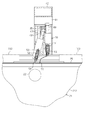
図6及び図7に示すように、前記支持枠26の両側面には、ラック31が固定されている。両フレーム側壁部212の外側面には、正逆回転可能な枠移動駆動モータ32が固定され、そのモータ軸には前記ラック31と噛合するピニオン33が取り付けられている。そして、枠移動駆動モータ32の駆動により、図8〜図9に示すように、ピニオン33とラック31との噛合を介して支持枠26が案内レール25に沿ってフレーム側壁部212のホームポジション位置(図8に示す右端位置)と前記アーム部214の先端位置との間を往復動される。   As shown in FIGS. 6 and 7, racks 31 are fixed to both side surfaces of the support frame 26. A frame moving drive motor 32 that can rotate forward and backward is fixed to the outer side surfaces of both frame side wall portions 212, and a pinion 33 that meshes with the rack 31 is attached to the motor shaft. The frame moving drive motor 32 drives the support frame 26 along the guide rail 25 through the engagement between the pinion 33 and the rack 31 as shown in FIGS. It is reciprocated between (the right end position shown in FIG. 8) and the tip position of the arm portion 214.

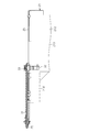
図1,図4及び図5に示すように、印刷機フレーム21のフレーム側壁部212の上端面には支持柱41が立設され、それらの支持柱41の上端間には梁部材42が架設されている。両支持柱41にはガイドレール43が設けられ、そのガイドレール43には昇降体44が支持されている。支持柱41の上端にはエアシリンダよりなる駆動手段としての昇降駆動シリンダ45が取り付けられ、そのピストンロッド451が前記昇降体44に連結されて、昇降駆動シリンダ45の駆動により、昇降体44がガイドレール43に沿って昇降される。   As shown in FIGS. 1, 4, and 5, a support column 41 is erected on the upper end surface of the frame side wall 212 of the printing machine frame 21, and a beam member 42 is installed between the upper ends of the support columns 41. Has been. Both support pillars 41 are provided with guide rails 43, and a lifting body 44 is supported on the guide rails 43. An elevating drive cylinder 45 as an air cylinder driving means is attached to the upper end of the support column 41, and its piston rod 451 is connected to the elevating body 44, and the elevating body 44 is guided by driving of the elevating drive cylinder 45. It is raised and lowered along the rail 43.

昇降体44には、サーボモータよりなる昇降駆動モータ48,49が搭載されており、昇降駆動モータ48,49により各昇降部材50,51が昇降される。左右の昇降部材50,51間には支持バー52,53が架設され、それらの支持バー52,53には、スキージ54及びドクター55が支持されている。このスキージ54及びドクター55は、支持枠26の移動領域の上部側において、スクリーン27による印刷位置に配置されている。そして、昇降駆動モータ48,49の駆動により、支持枠26の往復移動タイミングと同期してスキージ54及びドクター55が各別に昇降される。昇降体44,昇降駆動モータ48,49,昇降部材50,51,支持バー52,53などによりスキージ・ドクターユニット56が構成されている。   The elevating body 44 is equipped with elevating drive motors 48 and 49 made of servomotors, and the elevating members 50 and 51 are raised and lowered by the elevating drive motors 48 and 49. Support bars 52 and 53 are installed between the left and right elevating members 50 and 51, and a squeegee 54 and a doctor 55 are supported on the support bars 52 and 53. The squeegee 54 and the doctor 55 are arranged at a printing position by the screen 27 on the upper side of the moving area of the support frame 26. Then, the squeegee 54 and the doctor 55 are moved up and down separately in synchronization with the reciprocating movement timing of the support frame 26 by driving of the lift drive motors 48 and 49. A squeegee / doctor unit 56 is constituted by the elevating body 44, elevating drive motors 48 and 49, elevating members 50 and 51, support bars 52 and 53, and the like.

図11〜図14に示すように、フレーム側壁部212の前端部間には、駆動側支持軸61と、中間軸60,63,64とが回転可能に支持されている。両フレーム側壁部212のそれぞれ前端部には、起伏駆動シリンダ73が軸74を介して回転可能に支持され、そのピストンロッド731にはボード62の両側下面が軸75を介して連結されている。ボード62の前端には被動側支持軸65が支持されている。そして、前記駆動側支持軸61と被動側支持軸65との間に搬送ベルト66が周回支持されるとともに、その搬送ベルト66の周回方向中間部が中間軸60,64に支持される。一方のフレーム側壁部212には、搬送駆動モータ67が支持され、その搬送駆動モータ67の出力軸と駆動側支持軸61の一端部との間には、プーリ68,69及びベルト71が介在されていて、搬送駆動モータ67の駆動により、搬送ベルト66が印刷シートαの搬送方向に周回移動される。前記駆動側支持軸61,被動側支持軸65,中間軸60,64,ボード62,起伏駆動シリンダ73,搬送駆動モータ67などにより搬送ユニット76が構成されている。   As shown in FIGS. 11 to 14, a drive-side support shaft 61 and intermediate shafts 60, 63, and 64 are rotatably supported between the front end portions of the frame side wall portion 212. An undulating drive cylinder 73 is rotatably supported on the front end portions of both side wall portions 212 via a shaft 74, and both lower surfaces of the board 62 are connected to the piston rod 731 via shafts 75. A driven support shaft 65 is supported at the front end of the board 62. The conveyor belt 66 is supported by the drive side support shaft 61 and the driven side support shaft 65, and the intermediate portion of the conveyor belt 66 is supported by the intermediate shafts 60 and 64. One frame side wall 212 supports a conveyance drive motor 67, and pulleys 68 and 69 and a belt 71 are interposed between the output shaft of the conveyance drive motor 67 and one end of the drive-side support shaft 61. In this case, the conveyance belt 66 is moved in the conveyance direction of the print sheet α by driving the conveyance drive motor 67. A transport unit 76 is constituted by the drive side support shaft 61, the driven side support shaft 65, the intermediate shafts 60 and 64, the board 62, the undulation drive cylinder 73, the transport drive motor 67, and the like.

そして、起伏駆動シリンダ73のピストンロッド731の出没により、搬送ユニット76が起伏されて、図12に示す水平位置と、その水平位置から下方へ90度回転された図13に示す垂下位置とに配置される。垂下位置においては、搬送ベルト71は、中間軸63にも支持される。   As the piston rod 731 of the hoisting drive cylinder 73 moves up and down, the transport unit 76 is hoisted and arranged at the horizontal position shown in FIG. 12 and the drooping position shown in FIG. 13 rotated 90 degrees downward from the horizontal position. Is done. In the hanging position, the conveyor belt 71 is also supported by the intermediate shaft 63.

図15に示すように、両アーム部214の先端には、上下方向に延びて、下方に向かって開口した保持溝77が形成されており、この保持溝77に水平状態の被動側支持軸65の端部突出部が収容される。また、両アーム部214の先端には、アクチュエータ78が取り付けられ、そのアクチュエータ78のアーマチャ79が前記保持溝77の下端開口に対向している。そして、搬送ユニット76が水平位置に配置されると、その状態がセンサ(図示しない)によって検出されて、その検出に基づき、アクチュエータ78の作動により、アーマチャ79が突出される。このため、そのアーマチャ79により保持溝77の下端開口が閉鎖され、被動側支持軸65の断面四角形状の部分651が保持溝77内に保持されて、搬送ユニット76が水平位置に保持される。この保持溝77を有する部材,アクチュエータ78などにより保持ユニット80が構成されている。   As shown in FIG. 15, a holding groove 77 extending in the vertical direction and opening downward is formed at the tips of both arm portions 214, and the driven-side support shaft 65 in the horizontal state is formed in the holding groove 77. The end projections of are accommodated. An actuator 78 is attached to the distal ends of both arm portions 214, and an armature 79 of the actuator 78 faces the lower end opening of the holding groove 77. When the transport unit 76 is arranged at the horizontal position, the state is detected by a sensor (not shown), and the armature 79 is projected by the operation of the actuator 78 based on the detection. For this reason, the lower end opening of the holding groove 77 is closed by the armature 79, the section 651 having a quadrangular cross section of the driven support shaft 65 is held in the holding groove 77, and the transport unit 76 is held in the horizontal position. A holding unit 80 is constituted by the member having the holding groove 77, the actuator 78, and the like.

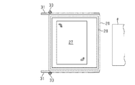
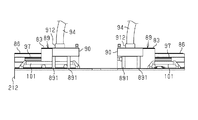
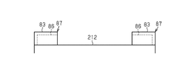
図16及び図17に示すように、前記支持柱41の前後両側において、両フレーム側壁部212の上端面にはガイドレール81が敷設されている。そのガイドレール81には、第1カバー83がその両側の車輪84において移動案内される。第1カバー83と隣接するように、フレーム側壁部212には、スライドレール85を介して第2カバー86が第1カバー83の移動方向と同方向に移動可能に支持されている。この第1カバー83と、第2カバー86とにより、カバーユニット87が構成されている。フレーム側壁部212には、ステー95が固定され、このステー95と第2カバー86との間には、スライドレール96が介在されている。また、第1カバー83と第2カバー86との間には、スライドレール97が介在されている。第1カバー83は、第2カバー86上に重なって、第2カバー86が第1カバー83内に収容される。   As shown in FIGS. 16 and 17, guide rails 81 are laid on the upper end surfaces of both side wall portions 212 on both the front and rear sides of the support column 41. The guide rail 81 is guided to move the first cover 83 on the wheels 84 on both sides thereof. A second cover 86 is supported on the frame side wall portion 212 via the slide rail 85 so as to be movable in the same direction as the movement direction of the first cover 83 so as to be adjacent to the first cover 83. The first cover 83 and the second cover 86 constitute a cover unit 87. A stay 95 is fixed to the frame side wall 212, and a slide rail 96 is interposed between the stay 95 and the second cover 86. A slide rail 97 is interposed between the first cover 83 and the second cover 86. The first cover 83 overlaps the second cover 86, and the second cover 86 is accommodated in the first cover 83.

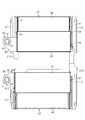
そして、図20に示すように、第2カバー86が第1カバー83内に収容されることなく、第1,第2カバー83,86の伸長状態において、カバーユニット87は、前記支持枠26の移動領域の上方を覆う閉鎖状態となる。図21に示すように、第1カバー83が第2カバー86上に重なった状態においては、前記支持枠26の印刷時の移動領域が開放された状態となる。図22に示すように、第2カバー86に第1カバー83が重なるとともに、両カバー83,86が印刷機フレーム21の外部側に移動した状態においては、印刷機フレーム21の上部が全面的に開放される。この全面開放状態において、第1,第2カバー86は、前記スライドレール96を介して前記ステー95に支持される。   Then, as shown in FIG. 20, the second cover 86 is not housed in the first cover 83, and the cover unit 87 is in the extended state of the first and second covers 83, 86. It will be in the closed state which covers the upper part of a movement area | region. As shown in FIG. 21, when the first cover 83 overlaps the second cover 86, the movement area of the support frame 26 during printing is opened. As shown in FIG. 22, when the first cover 83 overlaps the second cover 86 and the covers 83 and 86 are moved to the outside of the printing machine frame 21, the upper part of the printing machine frame 21 is entirely covered. Opened. In the fully open state, the first and second covers 86 are supported by the stay 95 via the slide rail 96.

図16〜図19に示すように、第1カバー83の一方の側壁831には複数の小孔からなる開口としての通気口88が形成されている。一方、フレーム側壁部212上には、吸気ユニット89が脚891を介して搭載されている。その吸気ユニット89は、風箱90内にモータ及びファン(図示しない)を内蔵したブロワ91を備え、風箱90には、第1カバー83側に位置する開口としての吸気口93と、ダクト94を接続した排気口912と、が備えられている。そして、前記第1カバー83が図16及び図20の閉鎖位置に配置されたときに、前記通気口88と吸気口93とがシール92内の狭い空間を介して連通される。この状態で、ブロワ91が作動されると、カバーユニット87内のエアが通気口88及び吸気口93を介して風箱90内に吸引され、排気口912及びダクト94を介して排気される。   As shown in FIGS. 16 to 19, a vent hole 88 as an opening made up of a plurality of small holes is formed on one side wall 831 of the first cover 83. On the other hand, an intake unit 89 is mounted on the frame side wall portion 212 via legs 891. The air intake unit 89 includes a blower 91 incorporating a motor and a fan (not shown) in a wind box 90. The air box 90 has an air inlet 93 as an opening located on the first cover 83 side, and a duct 94. , And an exhaust port 912 connected thereto. When the first cover 83 is disposed at the closed position shown in FIGS. 16 and 20, the vent 88 and the intake port 93 communicate with each other through a narrow space in the seal 92. When the blower 91 is operated in this state, the air in the cover unit 87 is sucked into the wind box 90 through the vent hole 88 and the intake port 93 and is exhausted through the exhaust port 912 and the duct 94.

前記カバーユニット87の移動領域の両側及び前記支持柱41の上端部間には、手摺101,102がそれぞれ設けられ、作業者が片手で手摺101,102を把持することにより、スクリーン枠28の清掃などの作業を安定して行うことができるようになっている。   Handrails 101 and 102 are provided on both sides of the moving area of the cover unit 87 and between the upper ends of the support columns 41, respectively, and the operator holds the handrails 101 and 102 with one hand to clean the screen frame 28. Etc. can be performed stably.

なお、フレーム側壁部212の上端にはカバー103が着脱可能に設けられる。
前部側の支持柱41の前面には、各種の操作ボタンなどを有する操作盤104と、各種の情報を表示する液晶パネルよりなる表示装置105が設置されている。
A cover 103 is detachably provided at the upper end of the frame side wall 212.
On the front surface of the support column 41 on the front side, an operation panel 104 having various operation buttons and a display device 105 including a liquid crystal panel for displaying various information are installed.

前記のように構成された印刷機は以下のように作用する。
印刷動作開始前の状態は、カバーユニット87が支持枠26の往復動範囲を覆う位置に配置される。また、搬送ユニット76が水平位置に配置されて、保持ユニット80によりその位置に保持される。さらに、昇降駆動シリンダ45により昇降体44が下方位置に配置され、この状態で、スキージ54及びドクター55が上方の待機位置に配置されている。
The printer configured as described above operates as follows.
In the state before the printing operation is started, the cover unit 87 is disposed at a position covering the reciprocating range of the support frame 26. Further, the transport unit 76 is disposed at the horizontal position and is held at that position by the holding unit 80. Further, the elevating body 44 is arranged at the lower position by the elevating drive cylinder 45, and in this state, the squeegee 54 and the doctor 55 are arranged at the upper standby position.

印刷動作が開始されると、印刷胴22の間欠回転により、印刷シートαが1枚ずつ搬送される。それと同時に、支持枠26が枠移動駆動モータ32の駆動によるラック31とピニオン33との噛合を介して往復動されるとともに、スキージ54及びドクター55がそれぞれ異なるタイミングで昇降されて、印刷胴22上の印刷シートに印刷が実行される。印刷が終了された印刷シートαは、搬送ユニット76によりスクリーン印刷機の下流側の次工程に送られる。   When the printing operation is started, the printing sheets α are conveyed one by one by the intermittent rotation of the printing cylinder 22. At the same time, the support frame 26 is reciprocated through the engagement between the rack 31 and the pinion 33 driven by the frame movement drive motor 32, and the squeegee 54 and the doctor 55 are moved up and down at different timings. Printing is performed on the print sheet. The printing sheet α for which printing has been completed is sent to the next process on the downstream side of the screen printer by the transport unit 76.

このとき、スクリーン枠28上などのインクから揮発性物質がカバーユニット87内に漂うが、このカバーユニット87内の揮発性物質は、吸気ユニット89によって吸引されて、ダクト94を介して外部に排気される。   At this time, volatile substances drift from the ink on the screen frame 28 into the cover unit 87. The volatile substances in the cover unit 87 are sucked by the intake unit 89 and exhausted to the outside through the duct 94. Is done.

そして、印刷作業が終了した場合は、昇降体44が昇降駆動シリンダ45により待機位置から上昇されて、スキージ54及びドクター55が退避位置に配置される。
支持枠26やスクリーン枠28の上面側に対する清掃などのメンテナンスを実行する場合には、第21図に示すように、カバーユニット87の第1カバー83を第2カバー86上に重なる位置に移動させれば、支持枠26及びスクリーン枠28の上方を開放して、メンテナンス作業を行なうことができる。印刷機フレーム21の上部を全面的に開放して、支持枠26及びスクリーン枠28のさらに上方を大きく開放させる場合は、図22に示すように、重なった状態の第1カバー83及び第2カバー86を同図22に示す外端位置に移動させればよい。
When the printing operation is completed, the lifting / lowering body 44 is lifted from the standby position by the lifting / lowering drive cylinder 45, and the squeegee 54 and the doctor 55 are disposed at the retracted position.
When performing maintenance such as cleaning on the upper surface side of the support frame 26 and the screen frame 28, the first cover 83 of the cover unit 87 is moved to a position overlapping the second cover 86 as shown in FIG. Then, maintenance work can be performed by opening the upper part of the support frame 26 and the screen frame 28. When the upper portion of the printing machine frame 21 is fully opened and the support frame 26 and the screen frame 28 are further opened upward, as shown in FIG. 22, the first cover 83 and the second cover in an overlapping state are used. 86 may be moved to the outer end position shown in FIG.

一方、印刷作業を停止している状態において、図13に示すように、搬送ユニット76を起伏駆動シリンダ73により垂下位置に移動させれば、フレーム側壁部212のアーム部214間が開放されるため、作業者はアーム部214間に入り込んで、メンテナンスなどを行なうことができる。さらに、搬送ユニット76の垂下状態において、図10に示すように、スクリーン枠28が支持された支持枠26を前記アーム部214の先端側の移動端に移動させれば、作業者がアーム部214間においてスクリーン枠28の下側に潜り込むことができ、そのスクリーン枠28の下面などのメンテナンスを実行できる。   On the other hand, when the printing operation is stopped, as shown in FIG. 13, if the transport unit 76 is moved to the hanging position by the undulating drive cylinder 73, the space between the arm portions 214 of the frame side wall portion 212 is opened. The operator can enter between the arm portions 214 and perform maintenance or the like. Further, when the transport unit 76 is in the suspended state, as shown in FIG. 10, if the support frame 26 that supports the screen frame 28 is moved to the moving end on the distal end side of the arm portion 214, the operator can move the arm portion 214. It is possible to sink into the lower side of the screen frame 28 and perform maintenance on the lower surface of the screen frame 28.

本実施形態においては、以下の効果がある。
(1)印刷胴22を回転させるための回転駆動モータ24が印刷機フレーム21のフレーム側壁部212に支持されて、同モータ24の出力軸が印刷胴22に直結されている。このため、印刷胴22を回転させる回転駆動モータ24や、その回転駆動モータ24と印刷胴22との間の動力伝達機構を印刷機フレーム21内に設ける必要はない。従って、印刷機フレーム21内に他部品を搭載するためのスペースを余裕を持って確保できるとともに、前記回転駆動モータ24や動力伝達機構を印刷機フレーム21の内部においてメンテナンスするような煩雑さを回避できる。
The present embodiment has the following effects.
(1) A rotation drive motor 24 for rotating the printing cylinder 22 is supported by the frame side wall 212 of the printing machine frame 21, and the output shaft of the motor 24 is directly connected to the printing cylinder 22. For this reason, it is not necessary to provide the rotary drive motor 24 for rotating the printing cylinder 22 or the power transmission mechanism between the rotation drive motor 24 and the printing cylinder 22 in the printing machine frame 21. Therefore, it is possible to secure a sufficient space for mounting other components in the printing machine frame 21 and avoid the trouble of maintaining the rotation drive motor 24 and the power transmission mechanism inside the printing machine frame 21. it can.

(2)回転駆動モータ24が印刷胴22に直結されて、それらの間には動力伝達機構が介在されていないため、回転駆動モータ24と印刷胴22との間のバックラッシや動力伝達ロスを避けることができる。従って、印刷胴22を正確なタイミング及び速度で回転させて、印刷シートαの搬送を正確なタイミング及び速度で行なうことができ、高精度印刷に寄与できる。また、回転駆動モータ24と印刷胴22とが直結されているため、それらの間の複雑な動力伝達機構は不要になって、構成が簡単になる。   (2) Since the rotation drive motor 24 is directly connected to the printing cylinder 22 and no power transmission mechanism is interposed between them, backlash and power transmission loss between the rotation drive motor 24 and the printing cylinder 22 are avoided. be able to. Accordingly, the printing cylinder 22 can be rotated at an accurate timing and speed by rotating the printing cylinder 22 at an accurate timing and speed, which can contribute to high-precision printing. Further, since the rotation drive motor 24 and the printing cylinder 22 are directly connected, a complicated power transmission mechanism between them is not necessary, and the configuration is simplified.

(3)支持枠26の搬送を駆動するための枠移動駆動モータ32をフレーム側壁部212の外側面に支持した。このことにより、その枠移動駆動モータ32を印刷機フレーム21の内部に設けた場合とは異なり、前記と同様に、印刷機フレーム21内に他部品を搭載するためのスペースを余裕を持って確保できるとともに、前記駆動モータや動力伝達機構を印刷機フレーム21の内部においてメンテナンスできる。従って、印刷機フレーム21の内部においてメンテナンスするような煩雑さを回避できる。   (3) The frame movement drive motor 32 for driving the conveyance of the support frame 26 is supported on the outer side surface of the frame side wall portion 212. As a result, unlike the case where the frame movement drive motor 32 is provided inside the printing press frame 21, a space for mounting other components in the printing press frame 21 is secured with a margin as described above. In addition, the drive motor and the power transmission mechanism can be maintained inside the printing machine frame 21. Accordingly, it is possible to avoid the troublesome maintenance in the printing machine frame 21.

(4)支持枠26と枠移動駆動モータ32との間の動力伝達機構はラック31とピニオン33だけであるため、動力伝達機構の構成を簡素化できて、コンパクトにできるとともに、バックラッシの影響を少なくできて、高精度印刷に寄与できる。   (4) Since the power transmission mechanism between the support frame 26 and the frame movement drive motor 32 is only the rack 31 and the pinion 33, the configuration of the power transmission mechanism can be simplified and compact, and the influence of backlash can be reduced. It can be reduced and can contribute to high-precision printing.

(5)スキージ・ドクターユニット56を支持する支持柱41が印刷機フレーム21のフレーム側壁部212の上端に支持されている。そして、スキージ54及びドクター55の両者を一体に昇降させる昇降駆動シリンダ45と、スキージ54及びドクター55をそれぞれ単独で昇降させる昇降駆動モータ48,49とが支持柱41に設けられている。従って、スキージ54及びドクター55を一体に、あるいは単独で昇降させるアクチュエータや、そのアクチュエータとスキージ54及びドクター55との間の動力伝達機構を印刷機フレーム21の内部に設ける必要がない。このため、構成が簡単になり、しかも、印刷機フレーム21内に他部品を搭載するためのスペースを余裕を持って確保できるとともに、前記アクチュエータや動力伝達機構を印刷機フレーム21の内部においてメンテナンスするような煩雑さを回避できる。   (5) A support column 41 that supports the squeegee / doctor unit 56 is supported by the upper end of the frame side wall 212 of the printing machine frame 21. The support column 41 is provided with a lift drive cylinder 45 that lifts and lowers both the squeegee 54 and the doctor 55 integrally, and lift drive motors 48 and 49 that lift and lower the squeegee 54 and the doctor 55 individually. Therefore, it is not necessary to provide an actuator for raising and lowering the squeegee 54 and the doctor 55 integrally or independently, and a power transmission mechanism between the actuator and the squeegee 54 and the doctor 55 inside the printing press frame 21. For this reason, the configuration is simplified, and a space for mounting other components in the printing machine frame 21 can be secured with sufficient margins, and the actuator and the power transmission mechanism are maintained inside the printing machine frame 21. Such complexity can be avoided.

(6)また、前記のように、スキージ54及びドクター55の両者を一体に昇降させる昇降駆動シリンダ45と、スキージ54及びドクター55をそれぞれ単独で昇降させる昇降駆動モータ48,49とが支持柱41に設けられている。このため、スキージ54及びドクター55の作動タイミングをバックラッシほとんどに影響されることなく、高精度に制御できて、印刷速度及び印刷品質の向上に有効である。   (6) As described above, the support column 41 includes the lift drive cylinder 45 that lifts and lowers both the squeegee 54 and the doctor 55 integrally, and the lift drive motors 48 and 49 that lift and lower the squeegee 54 and the doctor 55 individually. Is provided. For this reason, the operation timing of the squeegee 54 and the doctor 55 can be controlled with high accuracy without being affected by the backlash, and it is effective for improving the printing speed and the printing quality.

(7)搬送ベルトを有する66を有する搬送ユニット76が搬送動作位置である上方位置から90度回転した垂下位置に配置されるようになっている。従って、搬送ユニット76が垂下位置に配置された状態においては、作業者が印刷機フレーム21のアーム部214間に入り込むことができる。このため、作業者は、スキージ54やドクター55などの各種機構に近づくことができて、清掃などのメンテナンスを容易に行うことができる。また、支持枠26をアーム部214の先端側に移動させれば、支持枠26やスクリーン枠28の下面側を容易に清掃などのメンテナンスできる。   (7) A conveyance unit 76 having 66 having a conveyance belt is arranged at a drooping position rotated 90 degrees from an upper position which is a conveyance operation position. Therefore, in a state where the transport unit 76 is disposed at the hanging position, an operator can enter between the arm portions 214 of the printing machine frame 21. For this reason, the operator can approach various mechanisms such as the squeegee 54 and the doctor 55, and can easily perform maintenance such as cleaning. Further, if the support frame 26 is moved to the distal end side of the arm portion 214, maintenance such as cleaning of the lower surface side of the support frame 26 and the screen frame 28 can be easily performed.

(8)搬送ユニット76が水平位置に配置されると、被動側支持軸65の一端部が保持溝77内に位置するとともに、アクチュエータ78のアーマチャ79により保持溝77の下端開口が自動的に閉鎖される。従って、搬送ユニット76の搬送作用位置へのセットを容易に行なうことができる。   (8) When the transport unit 76 is disposed in the horizontal position, one end of the driven support shaft 65 is positioned in the holding groove 77 and the lower end opening of the holding groove 77 is automatically closed by the armature 79 of the actuator 78. Is done. Therefore, the transport unit 76 can be easily set to the transport operation position.

(9)前記のように、印刷胴22の回転駆動モータ24が印刷胴22に直結されて、印刷機フレーム21の外部に設置され、スキージ・ドクターユニット56が印刷機フレーム21の上部側に、搬送ユニット76が印刷機フレーム21の外側に配置されている。従って、印刷動作に直接作用する機構が印刷機フレーム21の外部側に位置して、内部側には設けられていないため、印刷機フレーム21の内部側に広い空間を形成できる。このため、作業者が印刷機フレーム21の内部に入り込んで、従来では行い得なかった種類のメンテナンス作業を実行できて、印刷機を最適状態に容易に保つことができる。また、印刷機フレーム21の内部空間を利用して、印刷機の制御機構などをその内部空間に設置することも可能になり、この場合は、印刷機外の制御機構など小型化したり、なくしたりすることが可能になり、印刷機全体のコンパクト化を図ることができる。   (9) As described above, the rotation drive motor 24 of the printing cylinder 22 is directly connected to the printing cylinder 22 and installed outside the printing machine frame 21, and the squeegee / doctor unit 56 is located on the upper side of the printing machine frame 21. A transport unit 76 is disposed outside the printing machine frame 21. Therefore, since a mechanism that directly acts on the printing operation is located on the outer side of the printing machine frame 21 and is not provided on the inner side, a wide space can be formed on the inner side of the printing machine frame 21. For this reason, an operator can enter the inside of the printing press frame 21 to perform a kind of maintenance work that could not be performed conventionally, and can easily keep the printing press in an optimum state. Also, it becomes possible to install the control mechanism of the printing press in the internal space using the internal space of the printing press frame 21. In this case, the control mechanism outside the printing press can be downsized or eliminated. Thus, the entire printing press can be made compact.

(10)スクリーン枠28などの印刷機構がカバーユニット87に覆われ、そのカバーユニット87内のエアが吸気ユニット89により吸引されて、ダクト94を通して排出される。従って、スクリーン枠28上などに存在するインクからの揮発性物質を含むエアが印刷機の外部に漂うことを抑えることができて、作業環境を改善することができる。   (10) The printing mechanism such as the screen frame 28 is covered by the cover unit 87, and the air in the cover unit 87 is sucked by the intake unit 89 and discharged through the duct 94. Therefore, it is possible to suppress the air containing volatile substances from the ink existing on the screen frame 28 from drifting outside the printing press, thereby improving the working environment.

(11)前部側の支持柱41の前面に、操作盤104と、表示装置105とが設置されているため、作業者は、印刷機に対する各種の操作を好適な高い位置において表示装置105を見ながら行なうことができる。従って、印刷機を容易かつ適切にコントロールでき、作業者に対する作業負担を軽減できる。   (11) Since the operation panel 104 and the display device 105 are installed on the front surface of the support column 41 on the front side, an operator can perform various operations on the printing press at a suitable high position. You can do it while watching. Therefore, the printing press can be controlled easily and appropriately, and the work burden on the operator can be reduced.

(変更例)
本発明は前記実施形態に限定されるものではなく、以下のような態様で具体化してもよい。
(Example of change)
The present invention is not limited to the embodiment described above, and may be embodied in the following manner.

・前記実施形態では、枚葉の印刷シートαに印刷を行なうようにしたが、ロール巻きされ、帯状に連続する印刷シートに対して印刷を行なうように構成すること。
・印刷胴22の回転駆動モータ24を印刷機フレーム21内に設けるとともに、その回転駆動モータ24と印刷胴22との間に動力伝達機構を設けること。
In the above-described embodiment, printing is performed on the sheet-like printing sheet α. However, printing is performed on a printing sheet that is wound in a roll and continuous in a strip shape.
A rotation driving motor 24 for the printing cylinder 22 is provided in the printing machine frame 21, and a power transmission mechanism is provided between the rotation driving motor 24 and the printing cylinder 22.

・枠移動駆動モータ32を印刷機フレーム21内に設けるとともに、その枠移動駆動モータ32とピニオン33との間に動力伝達機構を設けること。
・スキージ・ドクターユニット56の昇降駆動シリンダ45及び昇降駆動モータ48,49を印刷機フレーム21内に設けること。
A frame movement drive motor 32 is provided in the printing machine frame 21 and a power transmission mechanism is provided between the frame movement drive motor 32 and the pinion 33.
The elevating drive cylinder 45 and elevating drive motors 48 and 49 of the squeegee / doctor unit 56 are provided in the printing press frame 21.

(他の技術的思想)
前記実施形態から把握される技術的思想は以下の通りである。
(A)スクリーン枠を支持するための支持枠が印刷機フレームの上部に往復移動可能に設けられ、前記スクリーン枠上のインク対して作用するスキージ・ドクターユニットが前記支持枠の移動領域の上方に昇降可能に設けられるとともに、印刷シートを支持するための印刷胴が前記支持枠の移動領域の下部側に設けられたスクリーン印刷機において、
前記印刷胴を回転させるための駆動モータを前記印刷機フレームの外側部に備えるとともに、その駆動モータの出力軸が前記印刷胴の中心軸に直結され、前記スキージ・ドクターユニットが前記印刷機フレームの上端部に立設された支持柱に備えられたスクリーン印刷機。
(Other technical ideas)
The technical idea grasped from the embodiment is as follows.
(A) A support frame for supporting the screen frame is provided on the upper part of the printing machine frame so as to be reciprocally movable, and a squeegee / doctor unit acting on the ink on the screen frame is located above the moving region of the support frame. In a screen printing machine provided so as to be movable up and down, and a printing cylinder for supporting a printing sheet is provided on the lower side of the moving area of the support frame,
A drive motor for rotating the printing cylinder is provided on the outer side of the printing machine frame, an output shaft of the driving motor is directly connected to a central axis of the printing cylinder, and the squeegee / doctor unit is connected to the printing machine frame. A screen printing machine provided on a support column erected on the upper end.

(B)前記スキージ・ドクターユニットは、
前記支持柱に支持され、駆動手段によって下方位置と上方の退避位置との間において昇降される昇降部材と、
前記昇降部材上に設けられ、駆動手段によって上方の待機位置と、下方のスクリーン上の作用位置との間において昇降されるスキージと、
前記昇降部材上に設けられ、駆動手段によって上方の待機位置と、下方のスクリーン上の作用位置との間において昇降されるドクターと
を有する請求項1に記載のスクリーン印刷機。
(B) The squeegee doctor unit is
An elevating member supported by the support pillar and moved up and down between a lower position and an upper retracted position by a driving means;
A squeegee that is provided on the elevating member and is moved up and down between the upper standby position by the driving means and the operating position on the lower screen;
2. The screen printing machine according to claim 1, further comprising a doctor that is provided on the elevating member and is moved up and down between an upper standby position and an operation position on the lower screen by a driving unit.

(C)印刷機構を上方から包囲するカバーがフレーム上に備えられた印刷機において、
前記カバー内のエアをカバー外に吸引するための吸気ユニットを有する印刷機。
(D)前記印刷機構がスクリーン印刷機構である前記技術的思想(C)項に記載の印刷機。
(C) In a printing machine in which a cover surrounding the printing mechanism from above is provided on the frame,
A printing machine having an air intake unit for sucking air in the cover out of the cover.
(D) The printing machine according to item (C), wherein the printing mechanism is a screen printing mechanism.

(E)前記カバーは、印刷機構の上方に位置する包囲位置と、その包囲位置から横方向へ退避する退避位置との間を移動可能であり、前記吸気ユニットは、前記フレームに搭載され、前記カバーが包囲位置にあるときにそのカバー側壁の吸気孔と対向される前記技術的思想(D)項に記載の印刷機。   (E) The cover is movable between an encircling position located above the printing mechanism and a retreating position retracted laterally from the encircling position, and the intake unit is mounted on the frame, The printing machine according to item (D), wherein the cover is opposed to an air intake hole on a side wall of the cover when the cover is in the surrounding position.

21…印刷機フレーム、22…印刷胴、24…回転駆動モータ、26…支持枠、27…スクリーン、28…スクリーン枠、31…ラック、32…枠移動駆動モータ、33…ピニオン、41…支持柱、45…昇降駆動シリンダ、48…昇降駆動モータ、49…昇降駆動モータ、50…昇降部材、51…昇降部材、54…スキージ、55…ドクター、56…スキージ・ドクターユニット、67…搬送駆動モータ、73…起伏駆動シリンダ、76…搬送ユニット、80…保持ユニット、87…カバーユニット、89…吸気ユニット。   DESCRIPTION OF SYMBOLS 21 ... Printing machine frame, 22 ... Printing cylinder, 24 ... Rotary drive motor, 26 ... Support frame, 27 ... Screen, 28 ... Screen frame, 31 ... Rack, 32 ... Frame movement drive motor, 33 ... Pinion, 41 ... Support pillar 45 ... Elevating drive cylinder, 48 ... Elevating drive motor, 49 ... Elevating drive motor, 50 ... Elevating member, 51 ... Elevating member, 54 ... Squeegee, 55 ... Doctor, 56 ... Squeegee / doctor unit, 67 ... Conveying drive motor, 73: undulating drive cylinder, 76: transport unit, 80: holding unit, 87: cover unit, 89: intake unit.

Claims (3)

スクリーン枠が支持される支持枠をその下部の印刷胴に対して印刷シートの搬送方向に沿って往復動されるスクリーン印刷機において、
前記スクリーン枠の両側にラックが設けられ、フレームの両側に設けられた駆動モータの出力軸にピニオンが設けられるとともに、そのピニオンが前記ラックに噛合されたスクリーン印刷機。
In a screen printing machine in which a support frame on which a screen frame is supported is reciprocated along a conveyance direction of a print sheet with respect to a lower printing cylinder,
A screen printing machine in which racks are provided on both sides of the screen frame, pinions are provided on output shafts of drive motors provided on both sides of the frame, and the pinions are meshed with the racks.
前記スクリーン枠の前記搬送方向の下流側に搬送ユニットが上部側の搬送位置と、その搬送位置から垂下された垂下位置とに移動可能に設けられ、搬送ユニットが搬送位置に位置したときに、その状態を検出して搬送ユニットを搬送位置に保持する保持ユニットが設けられた請求項1に記載のスクリーン印刷機。   A transport unit is provided downstream of the screen frame in the transport direction so as to be movable between an upper transport position and a hanging position depending on the transport position, and when the transport unit is positioned at the transport position, The screen printing machine according to claim 1, further comprising a holding unit that detects a state and holds the transport unit at a transport position. 搬送ユニットが搬送位置から直角に垂下されるようにした請求項2に記載のスクリーン印刷機。   The screen printing machine according to claim 2, wherein the transport unit is suspended at a right angle from the transport position.
JP2016022827A 2016-02-09 2016-02-09 Screen printing machine Active JP6717608B2 (en)

Priority Applications (1)

Application Number Priority Date Filing Date Title
JP2016022827A JP6717608B2 (en) 2016-02-09 2016-02-09 Screen printing machine

Applications Claiming Priority (1)

Application Number Priority Date Filing Date Title
JP2016022827A JP6717608B2 (en) 2016-02-09 2016-02-09 Screen printing machine

Publications (2)

Publication Number Publication Date
JP2017140744A true JP2017140744A (en) 2017-08-17
JP6717608B2 JP6717608B2 (en) 2020-07-01

Family

ID=59628304

Family Applications (1)

Application Number Title Priority Date Filing Date
JP2016022827A Active JP6717608B2 (en) 2016-02-09 2016-02-09 Screen printing machine

Country Status (1)

Country Link
JP (1) JP6717608B2 (en)

Cited By (1)

* Cited by examiner, † Cited by third party
Publication number Priority date Publication date Assignee Title
CN114872427A (en) * 2022-05-10 2022-08-09 湖南远超环保科技有限公司 Prevent plastic bottle silk screen printing device of jam leak protection

Cited By (2)

* Cited by examiner, † Cited by third party
Publication number Priority date Publication date Assignee Title
CN114872427A (en) * 2022-05-10 2022-08-09 湖南远超环保科技有限公司 Prevent plastic bottle silk screen printing device of jam leak protection
CN114872427B (en) * 2022-05-10 2023-08-29 湖南远超环保科技有限公司 Anti-blocking and anti-omission plastic bottle screen printing device

Also Published As

Publication number Publication date
JP6717608B2 (en) 2020-07-01

Similar Documents

Publication Publication Date Title
CN106004091B (en) Multistation samsara digital-code printer
CN103909762B (en) The automatic mounting device of card class books
JP2014180762A (en) Recording device
JP6717608B2 (en) Screen printing machine
CN108099369B (en) LED circuit board vision printer
US10471705B2 (en) Printing machine
JP2017140743A (en) Screen printer
ES2574505T3 (en) Product decoration machine
KR20100017172A (en) Gantry work apparatus
KR200414113Y1 (en) Heavy board cutting device
JP2005014343A (en) Inkjet printer
CN211003838U (en) Horizontal line magnetic conveying plate placing machine
JP2015058984A (en) Inkjet recorder and inkjet recording method
CN209193034U (en) A kind of silk-screen feeding device with vertical feeding direction
JP2017140817A (en) Printer
JPH0867414A (en) Spreading machine
KR101064551B1 (en) Apparatus for support of horizontal in flat-board printer
JP2009043846A (en) Substrate conveying device
JP5428754B2 (en) Droplet ejection device and method for controlling droplet ejection device
CN216885791U (en) Printing machine simple to operate
JP2020131517A (en) Printer
JP2019181916A (en) Inkjet printer
CN114227835B (en) Two-sided milling flutes device of plank
CN220498263U (en) Oven support double-sided welding processing equipment
CN216443280U (en) Printing device for drying printing ink on surface of paper bag

Legal Events

Date Code Title Description
A621 Written request for application examination

Free format text: JAPANESE INTERMEDIATE CODE: A621

Effective date: 20190208

A977 Report on retrieval

Free format text: JAPANESE INTERMEDIATE CODE: A971007

Effective date: 20191113

A131 Notification of reasons for refusal

Free format text: JAPANESE INTERMEDIATE CODE: A131

Effective date: 20191203

A521 Request for written amendment filed

Free format text: JAPANESE INTERMEDIATE CODE: A523

Effective date: 20200131

TRDD Decision of grant or rejection written
A01 Written decision to grant a patent or to grant a registration (utility model)

Free format text: JAPANESE INTERMEDIATE CODE: A01

Effective date: 20200609

A61 First payment of annual fees (during grant procedure)

Free format text: JAPANESE INTERMEDIATE CODE: A61

Effective date: 20200611

R150 Certificate of patent or registration of utility model

Ref document number: 6717608

Country of ref document: JP

Free format text: JAPANESE INTERMEDIATE CODE: R150

R250 Receipt of annual fees

Free format text: JAPANESE INTERMEDIATE CODE: R250