JP2017140686A - Electric power tool, battery pack, and electrically-driven tool system - Google Patents
Electric power tool, battery pack, and electrically-driven tool system Download PDFInfo
- Publication number
- JP2017140686A JP2017140686A JP2016025294A JP2016025294A JP2017140686A JP 2017140686 A JP2017140686 A JP 2017140686A JP 2016025294 A JP2016025294 A JP 2016025294A JP 2016025294 A JP2016025294 A JP 2016025294A JP 2017140686 A JP2017140686 A JP 2017140686A
- Authority
- JP
- Japan
- Prior art keywords
- battery
- tool
- terminal
- information
- battery pack
- Prior art date
- Legal status (The legal status is an assumption and is not a legal conclusion. Google has not performed a legal analysis and makes no representation as to the accuracy of the status listed.)
- Pending
Links
Images


Classifications
-
- Y—GENERAL TAGGING OF NEW TECHNOLOGICAL DEVELOPMENTS; GENERAL TAGGING OF CROSS-SECTIONAL TECHNOLOGIES SPANNING OVER SEVERAL SECTIONS OF THE IPC; TECHNICAL SUBJECTS COVERED BY FORMER USPC CROSS-REFERENCE ART COLLECTIONS [XRACs] AND DIGESTS
- Y02—TECHNOLOGIES OR APPLICATIONS FOR MITIGATION OR ADAPTATION AGAINST CLIMATE CHANGE
- Y02E—REDUCTION OF GREENHOUSE GAS [GHG] EMISSIONS, RELATED TO ENERGY GENERATION, TRANSMISSION OR DISTRIBUTION
- Y02E60/00—Enabling technologies; Technologies with a potential or indirect contribution to GHG emissions mitigation
- Y02E60/10—Energy storage using batteries
Abstract
Description
本発明は、電動工具、電池パック及びこれらを備える電動工具システムに関する。 The present invention relates to an electric tool, a battery pack, and an electric tool system including these.
一又は複数の二次電池を収容した電池パックを駆動源とする各種電動工具が広く普及している。この種の電動工具には、プラス端子及びマイナス端子を含む1対の電極端子と、電池パックの信号端子からの信号が入力される信号端子とが設けられる。そして、二次電池が過放電状態や高温状態等の異常状態に近づくと、電池パックの信号端子を介してモータ停止信号が入力され、電動工具の駆動が停止される。 Various electric tools using a battery pack containing one or a plurality of secondary batteries as a drive source are widely used. This type of electric tool is provided with a pair of electrode terminals including a plus terminal and a minus terminal, and a signal terminal to which a signal from a signal terminal of the battery pack is input. When the secondary battery approaches an abnormal state such as an overdischarge state or a high temperature state, a motor stop signal is input through the signal terminal of the battery pack, and the driving of the electric tool is stopped.
また、二次電池の温度上昇等に起因する電池パックの故障を抑制するため、電動工具に対して様々な提案がなされている。例えば、下記特許文献1に開示された電動工具には、工具本体及び電池パックのそれぞれにデータ通信用の端子が新たに設けられ、当該端子を介して、電池状態を示すデータを電池パックから工具本体に送信することにより、工具本体において電池状態に応じた制御を可能としている。 In addition, various proposals have been made for power tools in order to suppress the failure of the battery pack due to the temperature rise of the secondary battery. For example, in the electric power tool disclosed in Patent Document 1 below, a data communication terminal is newly provided in each of the tool body and the battery pack, and data indicating the battery state is transmitted from the battery pack to the tool via the terminal. By transmitting to the main body, the tool main body can be controlled according to the battery state.
しかしながら、上記した電動工具では、工具本体及び電池パックに、1対の電極端子と、モータ停止信号用の信号端子とに加えて、データ通信用の端子を新たに設けなければならないため、端子数が増えてしまうこととなる。その結果、コストがかさむという問題があった。 However, in the power tool described above, the tool body and the battery pack must be provided with a new data communication terminal in addition to the pair of electrode terminals and the motor stop signal signal terminal. Will increase. As a result, there is a problem that the cost is increased.
かかる課題に鑑み、本発明は、電池パックの劣化及び短寿命化を抑制可能且つ低コストな電動工具及び電池パックを提供することを目的とする。 In view of such a problem, an object of the present invention is to provide a low-cost electric tool and battery pack that can suppress deterioration and shortening of life of the battery pack.
上記課題を解決するために、本発明に係る電動工具は、モータと、モータ停止信号を出力可能な電池側信号端子を有する第1の電池パック及びシリアル通信によるデータの送受信が可能な電池側通信端子を有する第2の電池パックのいずれをも接続可能な接続手段と、接続手段に接続された電池パックの種別に応じて、モータの制御を行う制御手段と、を備え、接続手段は、電池側信号端子及び電池側通信端子のいずれにも接続可能且つモータ停止信号の入力及びシリアル通信によるデータの送受信が可能な工具側通信端子を有し、制御手段は、接続手段に第2の電池パックが接続された場合、電池側通信端子及び工具側通信端子を介して受信されたデータに基づき、モータの制御を行うことを特徴とする。 In order to solve the above problems, an electric power tool according to the present invention includes a motor, a first battery pack having a battery-side signal terminal capable of outputting a motor stop signal, and battery-side communication capable of transmitting and receiving data by serial communication. A connecting means capable of connecting any of the second battery packs having a terminal, and a control means for controlling the motor according to the type of the battery pack connected to the connecting means. A tool-side communication terminal that can be connected to both the side signal terminal and the battery-side communication terminal, and that is capable of inputting a motor stop signal and transmitting / receiving data by serial communication, and the control means includes a second battery pack in the connection means Is connected, the motor is controlled based on the data received via the battery side communication terminal and the tool side communication terminal.
かかる構成によれば、工具側通信端子は、信号の出力のみが可能な電池側信号端子及びシリアル通信によるデータの送受信が可能な電池側通信端子のいずれにも接続可能であるので、端子数を増やさずとも、既存の電池パックである第1の電池パック及びシリアル通信可能な第2の電池パックのいずれをも接続可能となる。したがって、互換性が確保されるとともに、コストの抑制が可能となる。また、第2の電池パックを接続して使用する場合、シリアル通信によりデータを送受信可能となるので、例えば電池の内部状態等の詳細な情報を受信して、内部状態に応じたモータの制御が可能となる。したがって、電池パックの劣化及び短寿命化を抑制可能となる。 According to such a configuration, the tool-side communication terminal can be connected to both the battery-side signal terminal that can output only signals and the battery-side communication terminal that can transmit and receive data by serial communication. Even if the number is not increased, both the first battery pack, which is an existing battery pack, and the second battery pack capable of serial communication can be connected. Therefore, compatibility is ensured and costs can be reduced. In addition, when the second battery pack is connected and used, data can be transmitted and received by serial communication. For example, detailed information such as the internal state of the battery is received and the motor is controlled according to the internal state. It becomes possible. Therefore, it is possible to suppress the deterioration and shortening of the life of the battery pack.
上記した電動工具において、工具側通信端子は、モータの停止中及び駆動中のいずれにおいても、電池側通信端子を介してデータの送受信が可能であることが好ましい。 In the above-described electric tool, it is preferable that the tool-side communication terminal can transmit and receive data via the battery-side communication terminal both when the motor is stopped and during driving.
かかる構成によれば、電池パックの内部状態の変動に応じてモータの的確な駆動制御が可能となるので、電池パックの劣化及び短寿命化の更なる抑制が可能となる。 According to such a configuration, accurate drive control of the motor can be performed in accordance with fluctuations in the internal state of the battery pack, so that deterioration of the battery pack and shortening of the life can be further suppressed.
また、制御手段は、接続手段に接続された電池パックに、工具側通信端子を介して電池情報要求を送信し、該電池情報要求に応じて工具側通信端子を介して電池情報を受信した場合、電池パックが第2の電池パックであると判断し、受信された電池情報に基づきモータの制御を行うことが好ましい。 In addition, when the control means transmits a battery information request to the battery pack connected to the connection means via the tool side communication terminal and receives battery information via the tool side communication terminal in response to the battery information request. The battery pack is preferably determined to be the second battery pack, and the motor is preferably controlled based on the received battery information.
かかる構成によれば、接続手段に接続された電池パックの種別を判別して、当該種別に応じたモータの制御が可能となるので、シリアル通信が可能な第2の電池パックが接続された場合、電池の内部状態等の詳細な情報を受信して、内部状態に応じたモータの制御が可能となる。したがって、電池パックの劣化及び短寿命化を抑制可能となる。 According to such a configuration, since the type of the battery pack connected to the connection means is determined and the motor can be controlled according to the type, the second battery pack capable of serial communication is connected. By receiving detailed information such as the internal state of the battery, the motor can be controlled in accordance with the internal state. Therefore, it is possible to suppress the deterioration and shortening of the life of the battery pack.
電池情報は、電池温度情報を含むことが好ましい。 The battery information preferably includes battery temperature information.
かかる構成によれば、電池温度に応じたモータの制御が可能となるので、電池パックの劣化及び短寿命化を抑制可能となる。 According to such a configuration, the motor can be controlled in accordance with the battery temperature, so that deterioration and shortening of the battery pack can be suppressed.
また、電池情報は、電池種類情報を含むことが好ましい。 The battery information preferably includes battery type information.
かかる構成によれば、電池パックの種類に応じたモータの制御が可能となるので、電池パックの劣化及び短寿命化を抑制可能となる。 According to such a configuration, the motor can be controlled according to the type of the battery pack, so that deterioration and shortening of the life of the battery pack can be suppressed.
また、電池情報は、電池定格情報を含むことが好ましい。 The battery information preferably includes battery rating information.
かかる構成によれば、電池の定格情報に応じたモータの制御が可能となるので、電池パックの劣化及び短寿命化を抑制可能となる。 According to such a configuration, the motor can be controlled in accordance with the rating information of the battery, so that the deterioration and shortening of the life of the battery pack can be suppressed.
また、電池情報は、電池容量情報を含むことが好ましい。 The battery information preferably includes battery capacity information.
かかる構成によれば、電池容量に応じたモータの制御が可能となるので、電池パックの劣化及び短寿命化を抑制可能となる。 According to such a configuration, the motor can be controlled in accordance with the battery capacity, so that the deterioration and shortening of the life of the battery pack can be suppressed.
また、電池情報は、電池使用履歴情報を含むことが好ましい。 The battery information preferably includes battery usage history information.
かかる構成によれば、電池の使用履歴に応じたモータの制御が可能となるので、電池パックの劣化及び短寿命化を抑制可能となる。 According to such a configuration, the motor can be controlled in accordance with the battery usage history, so that deterioration and shortening of the battery life can be suppressed.
また、電池情報は、放流電流値情報を含むことが好ましい。 The battery information preferably includes discharge current value information.
かかる構成によれば、放流電流値に応じたモータの制御が可能となるので、電池パックの劣化及び短寿命化を抑制可能となる。 According to such a configuration, the motor can be controlled in accordance with the discharge current value, so that the deterioration and shortening of the life of the battery pack can be suppressed.
上記した電動工具において、電池情報要求の送信後、所定時間が経過しても電池情報の受信が無い場合、制御手段は、第1の電池パックが接続手段に接続されたと判断し、工具側通信端子を介してモータ停止信号が入力されると、モータの駆動を停止することが好ましい。 In the power tool described above, if no battery information is received after the battery information request is transmitted, the control means determines that the first battery pack is connected to the connection means, and the tool side communication is performed. When a motor stop signal is input through the terminal, it is preferable to stop driving the motor.
かかる構成によれば、接続手段に接続された電池パックの種別を判別して、当該種別に応じたモータの制御が可能となるので、信号の出力のみが可能な既存の電池パックが接続された場合も、モータの駆動及びモータ停止信号の入力に基づくモータの駆動停止が可能となる。したがって、電池の互換性が確保される。 According to this configuration, since the type of the battery pack connected to the connection means is determined and the motor can be controlled according to the type, an existing battery pack that can only output signals is connected. Also in this case, the motor can be stopped based on the driving of the motor and the input of the motor stop signal. Therefore, battery compatibility is ensured.
また、制御手段は、送信端子及び受信端子を有するマイクロコンピュータであり、工具側通信端子は、送信端子及び受信端子に接続されることが好ましい。 The control means is preferably a microcomputer having a transmission terminal and a reception terminal, and the tool side communication terminal is preferably connected to the transmission terminal and the reception terminal.
かかる構成によれば、マイクロコンピュータは、一の工具側通信端子を介してシリアル通信によるデータの送受信が可能となるので、電池パックの内部状態等を示す詳細なデータに基づきモータの制御が可能となる。したがって、コストを抑制可能且つ電池パックの劣化及び短寿命化を抑制可能となる。 According to such a configuration, the microcomputer can transmit and receive data by serial communication via one tool-side communication terminal, so that the motor can be controlled based on detailed data indicating the internal state of the battery pack and the like. Become. Therefore, the cost can be suppressed and the deterioration and shortening of the life of the battery pack can be suppressed.
本発明の別の観点に係る電池パックは、少なくとも一つの二次電池と、信号を入力可能な工具側信号端子を有する第1の電動工具及びシリアル通信によるデータの送受信が可能な工具側通信端子を有する第2の電動工具のいずれをも接続可能な接続手段と、接続手段に接続された電動工具の種別に応じて、二次電池の放電制御を行う制御手段と、を備え、接続手段は、工具側信号端子及び工具側通信端子のいずれにも接続可能且つ信号の出力及びシリアル通信によるデータの送受信が可能な電池側通信端子を有し、制御手段は、接続手段に第2の電動工具が接続された場合、該第2の電動工具に、電池側通信端子を介して電池情報を送信することを特徴とする。 A battery pack according to another aspect of the present invention includes at least one secondary battery, a first electric tool having a tool-side signal terminal capable of inputting a signal, and a tool-side communication terminal capable of transmitting and receiving data by serial communication. Connecting means capable of connecting any of the second electric tools having control means, and control means for performing discharge control of the secondary battery in accordance with the type of the electric tool connected to the connecting means. And a battery-side communication terminal that can be connected to both the tool-side signal terminal and the tool-side communication terminal, and that can output signals and transmit / receive data by serial communication, and the control means has a second electric tool as the connection means. Is connected, the battery information is transmitted to the second electric tool via the battery side communication terminal.
かかる構成によれば、電池側通信端子は、信号の入力のみが可能な工具側信号端子及びシリアル通信によるデータの送受信が可能な工具側通信端子のいずれにも接続可能であるので、端子数を増やさずとも、既存の電動工具である第1の電動工具及びシリアル通信可能な第2の電動工具のいずれにも接続可能となる。したがって、互換性が確保されるとともに、コストの抑制が可能となる。また、第2の電動工具に接続して使用する場合、シリアル通信によりデータを送受信可能となるので、例えば電池の内部状態等の詳細な情報を送信することにより、電動工具側で内部状態に応じたモータの制御が可能となる。したがって、電池パックの劣化及び短寿命化を抑制可能となる。 According to such a configuration, the battery side communication terminal can be connected to both the tool side signal terminal capable of only inputting signals and the tool side communication terminal capable of transmitting and receiving data by serial communication. Even if the number is not increased, it can be connected to either the first electric tool which is an existing electric tool or the second electric tool capable of serial communication. Therefore, compatibility is ensured and costs can be reduced. In addition, when used by connecting to the second power tool, data can be transmitted and received by serial communication. For example, by transmitting detailed information such as the internal state of the battery, the power tool can respond to the internal state. The motor can be controlled. Therefore, it is possible to suppress the deterioration and shortening of the life of the battery pack.
上記した電池パックにおいて、電池側通信端子は、接続手段に接続された電動工具の停止中及び駆動中のいずれにおいても、工具側通信端子を介してデータの送受信が可能であることが好ましい。 In the battery pack described above, it is preferable that the battery-side communication terminal can transmit and receive data via the tool-side communication terminal both when the electric tool connected to the connecting means is stopped and during driving.
かかる構成によれば、電池パックを接続して使用する電動工具において、電池パックの内部状態の変動に応じた的確な駆動制御が可能となるので、電池パックの劣化及び短寿命化の更なる抑制が可能となる。 According to such a configuration, in an electric tool that is used with a battery pack connected, accurate drive control according to fluctuations in the internal state of the battery pack is possible, and therefore further suppression of deterioration and shortening of the battery pack is possible. Is possible.
また、制御手段は、接続手段に接続された電動工具から、電池側通信端子を介して電池情報要求を受信した場合、該電動工具が第2の電動工具であると判断し、該第2の電動工具に、電池側通信端子を介して電池情報を送信することが好ましい。 The control means determines that the power tool is the second power tool when the battery information request is received from the power tool connected to the connection means via the battery side communication terminal, and the second power tool is determined. The battery information is preferably transmitted to the electric tool via the battery side communication terminal.
かかる構成によれば、接続手段に接続された電動工具の種別を判別して、当該種別に応じて電池情報の送信の要否を判断可能となるので、シリアル通信が可能な第2の電動工具が接続された場合、電池の内部状態等の詳細な情報を送信して、当該第2の電動工具において、電池パックの内部状態に応じた駆動制御を実行させることが可能となる。したがって、電池パックの劣化及び短寿命化を抑制可能となる。 According to such a configuration, it is possible to determine the type of the power tool connected to the connection means and determine whether or not it is necessary to transmit the battery information according to the type, so the second power tool capable of serial communication. When is connected, detailed information such as the internal state of the battery is transmitted, and the second electric tool can execute drive control according to the internal state of the battery pack. Therefore, it is possible to suppress the deterioration and shortening of the life of the battery pack.
電池情報は、電池温度情報を含むことが好ましい。 The battery information preferably includes battery temperature information.
かかる構成によれば、電池温度に応じた電動工具の駆動制御が可能となるので、電池パックの劣化及び短寿命化を抑制可能となる。 According to such a configuration, drive control of the electric tool according to the battery temperature is possible, so that deterioration of the battery pack and shortening of the life can be suppressed.
また、電池情報は、電池種類情報を含むことが好ましい。 The battery information preferably includes battery type information.
かかる構成によれば、電池の種類に応じた電動工具の駆動制御が可能となるので、電池パックの劣化及び短寿命化を抑制可能となる。 According to such a configuration, drive control of the electric tool according to the type of battery can be performed, so that deterioration and shortening of the battery pack can be suppressed.
また、電池情報は、電池定格情報を含むことが好ましい。 The battery information preferably includes battery rating information.
かかる構成によれば、 According to such a configuration,
かかる構成によれば、電池の定格情報に応じた電動工具の駆動制御が可能となるので、電池パックの劣化及び短寿命化を抑制可能となる。 According to such a configuration, it becomes possible to control the driving of the electric tool according to the rating information of the battery, and therefore it is possible to suppress the deterioration and shortening of the life of the battery pack.
また、電池情報は、電池容量情報を含むことが好ましい。 The battery information preferably includes battery capacity information.
かかる構成によれば、電池容量に応じた電動工具の駆動制御が可能となるので、電池パックの劣化及び短寿命化を抑制可能となる。 According to such a configuration, drive control of the electric tool according to the battery capacity is possible, so that deterioration of the battery pack and shortening of the life can be suppressed.
また、電池情報は、電池使用履歴情報を含むことが好ましい。 The battery information preferably includes battery usage history information.
かかる構成によれば、電池の使用履歴に応じた電動工具の駆動制御が可能となるので、電池パックの劣化及び短寿命化を抑制可能となる。 According to such a configuration, drive control of the electric tool according to the battery usage history can be performed, so that deterioration and shortening of the battery pack can be suppressed.
また、電池情報は、放流電流値情報を含むことが好ましい。 The battery information preferably includes discharge current value information.
かかる構成によれば、放流電流値に応じたモータの制御が可能となるので、電池パックの劣化及び短寿命化を抑制可能となる。 According to such a configuration, the motor can be controlled in accordance with the discharge current value, so that the deterioration and shortening of the life of the battery pack can be suppressed.
上記した電池パックにおいて、制御手段は、送信端子及び受信端子を有するマイクロコンピュータであり、電池側通信端子は、送信端子及び受信端子に接続されることが好ましい。 In the battery pack described above, it is preferable that the control means is a microcomputer having a transmission terminal and a reception terminal, and the battery side communication terminal is connected to the transmission terminal and the reception terminal.
かかる構成によれば、マイクロコンピュータは、一の電池側通信端子を介してシリアル通信によるデータの送受信が可能となるので、電池パックの内部状態等を示す詳細なデータを電動工具へ送信して、当該詳細なデータに基づく電動工具の駆動制御を実行させることが可能となる。したがって、コストを抑制可能且つ電池パックの劣化及び短寿命化を抑制可能となる。 According to such a configuration, since the microcomputer can transmit and receive data by serial communication via one battery side communication terminal, the microcomputer transmits detailed data indicating the internal state of the battery pack to the electric tool, It becomes possible to execute drive control of the electric tool based on the detailed data. Therefore, the cost can be suppressed and the deterioration and shortening of the life of the battery pack can be suppressed.
本発明の更に別の観点に係る電動工具システムは、モータを有する電動工具と、少なくとも一つの二次電池を有し、モータの駆動源となる電池パックと、を備え、電池パックは、シリアル通信によるデータの送受信が可能な電池側通信端子と、二次電池の放電制御を行う電池側制御手段と、を備え、電動工具は、シリアル通信によるデータの送受信が可能であり、電池側通信端子に接続し、電池パックに電池情報要求を送信する工具側通信端子と、モータの制御を行う工具側制御手段と、を備え、電池側制御手段は、電池側通信端子を介して電池情報要求を受信すると、該電池側通信端子を介して電池情報を送信し、工具側制御手段は、工具側通信端子を介して電池情報を受信すると、該電池情報に基づきモータの制御を行うことを特徴とする。 An electric power tool system according to still another aspect of the present invention includes: an electric power tool having a motor; and a battery pack having at least one secondary battery and serving as a drive source of the motor. A battery-side communication terminal capable of transmitting and receiving data and battery-side control means for controlling discharge of the secondary battery, and the power tool can transmit and receive data by serial communication. A tool-side communication terminal for connecting and transmitting a battery information request to the battery pack; and a tool-side control means for controlling the motor. The battery-side control means receives the battery information request via the battery-side communication terminal. Then, the battery information is transmitted through the battery side communication terminal, and the tool side control means, when receiving the battery information through the tool side communication terminal, controls the motor based on the battery information. .
かかる構成によれば、工具側通信端子及び電池側通信端子が接続された、電動工具及び電池パック間におけるシリアル通信によるデータの送受信が可能となるので、端子数を増やさずとも、電池パックの内部状態等の詳細な情報を電池パックから電動工具へ送信して、内部状態に応じたモータの制御が可能となる。したがって、電池パックの劣化及び短寿命化を抑制可能となる。 According to such a configuration, it is possible to transmit and receive data by serial communication between the power tool and the battery pack, to which the tool side communication terminal and the battery side communication terminal are connected, so that the inside of the battery pack can be achieved without increasing the number of terminals. Detailed information such as the state is transmitted from the battery pack to the electric tool, and the motor can be controlled according to the internal state. Therefore, it is possible to suppress the deterioration and shortening of the life of the battery pack.
上記した電動工具システムにおいて、工具側通信端子及び電池側通信端子は、モータの停止中及び駆動中のいずれにおいても、互いにデータの送受信が可能であることが好ましい。 In the above-described electric tool system, it is preferable that the tool-side communication terminal and the battery-side communication terminal can transmit and receive data to each other while the motor is stopped and driven.
かかる構成によれば、電池パックの内部状態の変動に応じてモータの的確な駆動制御が可能となるので、電池パックの劣化及び短寿命化の更なる抑制が可能となる。 According to such a configuration, accurate drive control of the motor can be performed in accordance with fluctuations in the internal state of the battery pack, so that deterioration of the battery pack and shortening of the life can be further suppressed.
電池情報は、電池温度情報を含むことが好ましい。 The battery information preferably includes battery temperature information.
かかる構成によれば、電池温度に応じたモータの制御が可能となるので、電池パックの劣化及び短寿命化を抑制可能となる。 According to such a configuration, the motor can be controlled in accordance with the battery temperature, so that deterioration and shortening of the battery pack can be suppressed.
また、電池情報は、電池種類情報を含むことが好ましい。 The battery information preferably includes battery type information.
かかる構成によれば、電池パックの種類に応じたモータの制御が可能となるので、電池パックの劣化及び短寿命化を抑制可能となる。 According to such a configuration, the motor can be controlled according to the type of the battery pack, so that deterioration and shortening of the life of the battery pack can be suppressed.
また、電池情報は、電池定格情報を含むことが好ましい。 The battery information preferably includes battery rating information.
かかる構成によれば、電池の定格情報に応じたモータの制御が可能となるので、電池パックの劣化及び短寿命化を抑制可能となる。 According to such a configuration, the motor can be controlled in accordance with the rating information of the battery, so that the deterioration and shortening of the life of the battery pack can be suppressed.
また、電池情報は、電池容量情報を含むことが好ましい。 The battery information preferably includes battery capacity information.
かかる構成によれば、電池容量に応じたモータの制御が可能となるので、電池パックの劣化及び短寿命化を抑制可能となる。 According to such a configuration, the motor can be controlled in accordance with the battery capacity, so that the deterioration and shortening of the life of the battery pack can be suppressed.
また、電池情報は、電池使用履歴情報を含むことが好ましい。 The battery information preferably includes battery usage history information.
かかる構成によれば、電池の使用履歴に応じたモータの制御が可能となるので、電池パックの劣化及び短寿命化を抑制可能となる。 According to such a configuration, the motor can be controlled in accordance with the battery usage history, so that deterioration and shortening of the battery life can be suppressed.
また、電池情報は、放流電流値情報を含むことが好ましい。 The battery information preferably includes discharge current value information.
かかる構成によれば、放流電流値に応じたモータの制御が可能となるので、電池パックの劣化及び短寿命化を抑制可能となる。 According to such a configuration, the motor can be controlled in accordance with the discharge current value, so that the deterioration and shortening of the life of the battery pack can be suppressed.
上記した電動工具システムにおいて、工具側制御手段は、工具側送信端子及び工具側受信端子を有するマイクロコンピュータであり、工具側通信端子は、工具側送信端子及び工具側受信端子に接続されることが好ましい。 In the power tool system described above, the tool side control means is a microcomputer having a tool side transmission terminal and a tool side reception terminal, and the tool side communication terminal may be connected to the tool side transmission terminal and the tool side reception terminal. preferable.
かかる構成によれば、マイクロコンピュータは、工具側通信端子を介してシリアル通信によるデータの送受信が可能となるので、電池パックの内部状態等を示す詳細なデータに基づきモータの制御が可能となる。したがって、電池パックの劣化及び短寿命化を抑制可能となる。 According to such a configuration, the microcomputer can transmit and receive data by serial communication via the tool side communication terminal, so that the motor can be controlled based on detailed data indicating the internal state of the battery pack and the like. Therefore, it is possible to suppress the deterioration and shortening of the life of the battery pack.
また、電池側制御手段は、電池側送信端子及び電池側受信端子を有するマイクロコンピュータであり、電池側通信端子は、電池側送信端子及び電池側受信端子に接続されることが好ましい。 The battery-side control means is a microcomputer having a battery-side transmission terminal and a battery-side reception terminal, and the battery-side communication terminal is preferably connected to the battery-side transmission terminal and the battery-side reception terminal.
かかる構成によれば、マイクロコンピュータは、電池側通信端子を介してシリアル通信によるデータの送受信が可能となるので、電池パックの内部状態等を示す詳細なデータを電動工具へ送信して、当該詳細なデータに基づくモータが可能となる。したがって、電池パックの劣化及び短寿命化を抑制可能となる。 According to such a configuration, since the microcomputer can transmit and receive data by serial communication via the battery side communication terminal, the microcomputer transmits detailed data indicating the internal state of the battery pack and the like to the electric tool. A motor based on simple data becomes possible. Therefore, it is possible to suppress the deterioration and shortening of the life of the battery pack.
本発明に係る電動工具、電池パック及び電動工具システムによれば、コストを増大させることなく電池パックの劣化及び短寿命化を抑制可能となる。 According to the electric tool, the battery pack, and the electric tool system according to the present invention, it is possible to suppress the deterioration and shortening of the life of the battery pack without increasing the cost.
以下、本発明の実施の形態について、添付図面を参照して説明する。 Hereinafter, embodiments of the present invention will be described with reference to the accompanying drawings.
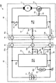
まず、図1を参照しながら、本発明の実施の形態に係る電動工具及び電池パックについて、説明する。図1は、本発明の実施の形態に係る電動工具及び電池パックを含む電動工具システムの電気的構成を示す回路図である。図1において、電動工具システム100は、本発明の実施の形態に係る電動工具10と、本発明の実施の形態に係る電池パック20とを含んで構成される。
First, a power tool and a battery pack according to an embodiment of the present invention will be described with reference to FIG. FIG. 1 is a circuit diagram showing an electrical configuration of a power tool system including a power tool and a battery pack according to an embodiment of the present invention. In FIG. 1, an
電池パック20は、充電が可能な電池パックであり、信号の入力のみが可能な電動工具(第1の電動工具)及びシリアル通信によるデータの送受信が可能な電動工具(第2の電動工具)のいずれにも接続可能な電池パックである。電池パック20は、図1に示されるように、電池組21、シャント抵抗22、電池MCU23、サーミスタ24、プラス端子25a、マイナス端子25b及び通信端子25cを備えている。電池パック20は、本発明の電池パックの一例である。
The
電池組21は、複数の二次電池セル21aが接続されて構成される。本実施の形態では、2つの二次電池セル21aが直列に接続されて電池組21を構成する。また、二次電池セル21aは、本実施の形態では定格電圧が3.6Vのリチウムイオン電池であるが、本発明はこれに限定されない。例えば定格電圧が1.2Vのニッケルカドミウム電池等も適用可能である。電池組21の正極側はプラス端子25aに接続され、負極側はシャント抵抗22を介してマイナス端子25bに接続される。
The battery set 21 is configured by connecting a plurality of
電池MCU23は、マイクロコンピュータであり、本発明の制御手段及び電池側制御手段の一例である。電池MCU23は、電池組21に並列に接続され、電池組21の電池温度Tと、電池組21の電池電圧VBと、電池組21から電動工具10へ流れる電流値Iとを監視する機能を有する。また、電池MCU23は、接続される電動工具の種別に応じて、通常モード及び通信モードの2つの制御モードのいずれかにより、放電制御を行う。ここで、通常モードとは、信号の入力のみが可能な第1の電動工具に接続された場合の制御モードである。一方、通信モードとは、シリアル通信によるデータの送受信が可能な第2の電動工具に接続された場合の制御モードである。通常モード及び通信モードの詳細については、後述する。
The
電池MCU23には、図1に示されるように、電源端子23a、GND端子23b、電流検知端子23c、温度検知端子23d、送信端子23e及び受信端子23fを含む6つの端子23a〜23fが設けられる。
As shown in FIG. 1, the
電源端子23aは、電池組21の正極側とプラス端子25aとの間に接続される。また、GND端子23bは、電池組21の負極側とシャント抵抗22の一端との間に接続される。電池MCU23は、電源端子23a及びGND端子23bを介して、電池組21から電力供給を受けて動作する。
The
また、電池MCU23は、電源端子23a及びGND端子23b間の電位差に基づき、電池組21の電圧値、すなわち電池電圧VBを検出する。電池MCU23は、電池組21の電池電圧VB及び電池組21に含まれる二次電池セル21aのセル数に基づき、1セルあたりの電圧値、すなわちセル電圧VCを算出し、セル電圧VCが所定の基準セル電圧値以下とならないように、電池電圧VBの監視を行う。本実施の形態では、所定の基準セル電圧値は3Vである。すなわち、電池電圧VBの基準電圧V0は3×2=6Vである。電池MCU23は、検出された電池電圧VBの基準電圧V0以下への低下を抑制するために、電池電圧VBの監視を行い、電池電圧VBが基準電圧V0に達すると、電池組21が過放電状態に近づいたと判断する。
The battery MCU23, based on the potential difference between the
電流検知端子23cは、シャント抵抗22の他端とマイナス端子25bとの間に接続される。電池MCU23は、GND端子23b及び電流検知端子23c間の電位差、すなわち電圧値Vsを検出し、この電圧値Vsとシャント抵抗22の抵抗値Rsとに基づき、シャント抵抗22を流れる電流、すなわち、電池組21から電動工具10へ流れる電流値I=Vs/Rsを検知する。電池MCU23は、電流値Iが所定の基準電流値I0を超えることを抑制するために、電流値Iの監視を行う。本実施の形態では、所定の基準電流値I0は100Aである。電池MCU23は、検出された電流値Iが基準電流値I0以上になると、電動工具10のモータ11(後述)が過電流状態に近づいたと判断する。
The
温度検知端子23dは、サーミスタ24に接続される。サーミスタ24は、温度に応じて抵抗値が変化する感温素子であり、電池組21に接触又は近接して配置される。サーミスタ24は、電池組21の電池温度Tを検出し、当該電池温度Tを、温度検知端子23dを介して電池MCU23に伝達する。電池MCU23は、電池温度Tが所定の基準温度T0を超えることを抑制するために、電池温度Tの監視を行う。本実施の形態では、基準温度T0は60℃である。電池MCU23は、検出された電池温度Tが基準温度T0に達すると、高温状態に近づいたと判断する。
The
送信端子23eは、抵抗26aを介して通信端子25cに接続される。また、受信端子23fは、抵抗26bを介して通信端子25cに接続される。電池MCU23は、送信端子23e及び通信端子25cを介してデータの送信を行い、通信端子25c及び受信端子23fを介してデータを受信する。つまり、電池MCU23は、通信端子25cを介して、データの送受信を行う。電池MCU23による通信端子25cを介するデータの送受信は、例えばUART(Universal Asynchronous Receiver Transmitter)方式やSCI(Serial Communication Interface)方式等のシリアル通信により行われる。また、電池MCU23は、送信端子23e及び通信端子25cを介して、二値信号を出力することも可能である。電池MCU23の通信端子25cを介する出力については、後述する。
The
プラス端子25a、マイナス端子25b及び通信端子25cは、電池パック20の電動工具との接続面(不図示)に設けられ、端子部25を構成する。端子部25は、本発明の接続手段の一例である。プラス端子25a及びマイナス端子25bは、放電用及び充電用の1対の電極端子である。通信端子25cは、本発明の電池側通信端子の一例であり、シリアル通信によるデータの送受信が可能な端子である。
The plus terminal 25 a, the
電動工具10は、コードレス式の電動工具であり、例えば丸鋸やインパクトドライバ等である。電動工具10は、信号の出力のみが可能な電池パック(第1の電池パック)及びシリアル通信によるデータの送受信が可能な電池パック(第2の電池パック)のいずれをも接続可能な電動工具であり、図1に示されるように、モータ11、スイッチング素子12、トリガスイッチ13、工具MCU14、プラス端子15a、マイナス端子15b及び通信端子15cを備えている。電動工具10は、本発明の電動工具の一例である。
The
モータ11は、DCモータであり、プラス端子15a及びマイナス端子15b間に直列に接続され、プラス端子15a及びマイナス端子15bを介して供給される電池パック20の電力により、回転駆動される。
The motor 11 is a DC motor, is connected in series between the
スイッチング素子12は、本実施の形態ではMOSFET(Metal Oxide Semiconductor Field Effect Transistor)であるが、本発明はこれに限定されない。例えば、IGBT(Insulated Gate Bipolar Transistor)やハイポーラトランジスタ等のデバイスであっても良い。スイッチング素子12は、ソースをマイナス端子15bに接続され、ドレインをモータ11に接続されるとともに、ゲートを工具MCU14に接続され、工具MCU14の制御に基づきオン・オフされることにより、モータ11の駆動と停止とを切り替える。
Although the switching
トリガスイッチ13は、プラス端子15a及び工具MCU14の間に接続され、作業者の操作に基づきオン・オフされることにより、工具MCU14の起動と停止とを切り替える。
The
工具MCU14は、マイクロコンピュータであり、本発明の制御手段及び工具側制御手段の一例である。工具MCU14は、モータ11の駆動を制御する機能を有する。工具MCU14は、通常モード及び通信モードの2つの制御モードにより、モータ11の駆動制御を行う。ここで、通常モードとは、信号の出力のみが可能な第1の電池パックに接続された場合の制御モードである。一方、通信モードとは、シリアル通信によるデータの送受信が可能な第2の電池パックに接続された場合の制御モードである。
The
電動工具10は図示せぬメモリを有し、当該メモリには、通信モードでのモータ11の駆動制御時に工具MCU14により使用されるデータが記憶されている。本実施の形態に係る電動工具10では、電池種類データ及び電池使用履歴データに応じて、4つの温度閾値、すなわち第1温度閾値T1、第2温度閾値T2、第3温度閾値T3及び第4温度閾値T4が記憶されている。ここで、4つの温度閾値の大小関係は、T1>T2>T3>T4である。
The
電池種類データは、電池パックの種別を示すデータである。電池使用履歴データは、例えば電池パックの使用回数を示すデータである。電動工具10は、例えば本実施の形態に係る電池パック20の種別を示す電池種別データ及び電池使用履歴データ「0〜30回」に対応して、4つの温度閾値T1=60℃、T2=55℃、T3=50℃、T4=45℃を記憶している。
The battery type data is data indicating the type of the battery pack. The battery usage history data is data indicating the number of times the battery pack is used, for example. The
第1温度閾値T1は、電動工具10の運転を停止する閾値である。つまり、電池温度Tが第1温度閾値T1よりも高い場合、工具MCU14は、電動工具10の運転を停止する。第2温度閾値T2は、電動工具10の最大出力を最大値の70%以下に制限する閾値である。つまり、電池温度Tが第2温度閾値T2よりも高く第1温度閾値T1未満である場合、工具MCU14は、電動工具10の最大出力を最大値の70%以下に制限する。同様に、第3温度閾値T3は、電動工具10の最大出力を最大値の80%以下に制限する閾値である。第4温度閾値T4は、電動工具10の最大出力を最大値の90%以下に制限する閾値である。これらの温度閾値は、一般に、電池パックに含まれる二次電池の温度耐性に応じて設定されるとともに、電池使用履歴が長いほど低い値となるように設定される。工具MCU14は、通信モードにおいて、メモリに記憶した4つの温度閾値を利用して、モータ11の駆動制御(通信モード処理)を行う。通信モード処理の詳細については、後述する。
The first temperature threshold T 1 is a threshold for stopping the operation of the
また、工具MCU14には、図1に示されるように、電源端子14a、GND端子14b、PWM制御端子14c、送信端子14d及び受信端子14eを含む5つの端子14a〜14eが設けられる。
Further, as shown in FIG. 1, the
電源端子14aは、トリガスイッチ13を介してプラス端子15a及びモータ11間に接続される。また、GND端子14bは、マイナス端子15b及びスイッチング素子12のソース間に接続される。工具MCU14は、作業者の操作によりトリガスイッチ13がオンされると、電源端子14a及びGND端子14bを介して、電池パック20から電力供給を受けて起動する。
The
PWM制御端子14cは、抵抗16を介してスイッチング素子12のゲートに接続される。工具MCU14は、スイッチング素子12をオン・オフするための駆動信号を、PWM制御端子14cを介して出力する。工具MCU14からの駆動信号がスイッチング素子12のゲートに入力されると、スイッチング素子12はオン状態となり、モータ11への電力の供給が開始され、モータ11が回転する。工具MCU14は、PWM制御端子14cを介して、パルス信号である駆動信号を出力し、スイッチング素子12のオン・オフをPWM制御することにより、モータ11の回転を制御する。
The
送信端子14dは、抵抗17aを介して通信端子15cに接続される。また、受信端子14eは、抵抗17bを介して通信端子15cに接続される。工具MCU14は、送信端子14d及び通信端子15cを介してデータの送信を行い、通信端子15c及び受信端子14eを介してデータを受信する。つまり、工具MCU14は、通信端子15cを介して、データの送受信を行う。工具MCU14による通信端子15cを介するデータの送受信は、例えばUART方式やSCI方式等のシリアル通信により行われる。また、工具MCU14は、通信端子15c及び受信端子14eを介して、二値信号を入力することも可能である。
The
プラス端子15a、マイナス端子15b及び通信端子15cは、電動工具10の電池パックとの接続面(不図示)に設けられ、端子部15を構成する。端子部15は、本発明の接続手段の一例である。プラス端子15a及びマイナス端子15bは、電池パックから電力の供給を受けるための1対の電極端子である。通信端子15cは、本発明の工具側通信端子の一例であり、シリアル通信によるデータの送受信が可能な端子である。
The plus terminal 15 a, the
電動工具10に電池パック20が接続される場合、電池パック20のプラス端子25a、マイナス端子25b及び通信端子25cが、それぞれ、電動工具10のプラス端子15a、マイナス端子15b及び通信端子15cに接続される。このように、各端子が接続された状態で、電動工具10及び電池パック20は電気的に接続され、電動工具10は、電池パック20から電力の供給を受けることが可能となるとともに、電池パック20との間で、通信端子15c及び通信端子25cを介するシリアル通信によるデータの送受信が可能となる。
When the
次に、電動工具10及び電池パック20間におけるデータの送受信について、説明する。まず、通常モードの場合について、図2を参照して説明する。図2は、本発明の実施の形態に係る電池パック20の通常モードにおける出力電圧波形を示す説明図である。
Next, transmission / reception of data between the
電池パック30は、通常モードにおいて、図2に示されるように、HIGHレベルであるVH及びLOWレベルであるVLのいずれかの電圧値を有する二値信号の出力を行う。図2に示される出力電圧波形は、信号の出力のみを行いシリアル通信を行わない第1の電池パックの場合と同様の出力電圧波形である。つまり、電池パック20は、通常モードにおいて、第1の電池パックと同様の放電制御を行う。
In the normal mode, as shown in FIG. 2, the
電池MCU23は、電池温度T、電池電圧VB及び電流値Iの3つの検出値を常時監視する。そして、電池MCU23は、これらの検出値に基づき、電池パック20が通常状態であるか異常状態に近づいた警告状態であるかを判断する。電池パック20が通常状態であると判断した場合、電池MCU23は、HIGHレベル信号VHを出力する。また、電池パック20が警告状態であると判断すると、電池MCU23は、電動工具の運転を禁止すべくLOWレベル信号VLを出力する。以下、HIGHレベル信号VHを運転許可信号と記載し、LOWレベル信号VLを運転禁止信号と記載することとする。運転禁止信号は、本発明のモータ停止信号の一例である。電池MCU23は、通常モードにおいて、送信端子23e及び通信端子25cを介して、運転許可信号及び運転禁止信号のいずれかを出力する。
Battery MCU23 monitors battery temperature T, the three detection value of the battery voltage V B and the current value I at all times. Then, based on these detection values, the
本実施の形態では、電池パック20の異常状態とは、電池組21の高温状態、電池組21の過放電状態及び電動工具10のモータ11の過電流状態のいずれかである。電池MCU23は、電池温度Tが基準温度T0以上の場合、電池組21が高温状態に近づいたと判断する。また、電池MCU23は、電池電圧VBが基準電圧V0以下の場合、電池組21が過放電状態に近づいたと判断する。また、電池MCU23は、電流値Iが基準電流値I0以上の場合、電動工具10のモータ11が過電流状態に近づいたと判断する。そして、電池MCU23は、電池パック20が高温状態、過放電状態及び過電流状態のいずれかに近づいたと判断する場合、電池パック20が異常状態に近づいた警告状態であると判断し、送信端子23eから出力する信号を、運転許可信号から運転禁止信号に切り替える。
In the present embodiment, the abnormal state of the
なお、電池パック20において、シャント抵抗22は、図1に示されるように、電池パック20から電動工具10へ電力供給を行う電源ライン上に配置されている。そのため、このシャント抵抗22を流れる電流値Iが基準電流値I0以上になると、電動工具10のモータ11にも所定値以上の電流が流れる過電流状態が発生し、モータ11のモータ部や回路部の焼損を招くおそれがある。また、電流値Iが基準電流値I0以上の状態で放電を続けると、電池組21の劣化をも招くおそれがある。そこで、本実施の形態では、電動工具10のモータ11の過電流状態についても、電池パック20の異常状態に含めることとする。
In the
次に、通信モードの場合について、図3を参照して説明する。図3は、本発明の実施の形態に係る電池パック20の通信モードにおける出力電圧波形を示す説明図である。
Next, the case of the communication mode will be described with reference to FIG. FIG. 3 is an explanatory diagram showing output voltage waveforms in the communication mode of the
電池MCU23は、通信モードにおいて、図3に示されるように、1組のパルス電圧信号をシリアル通信により送信する。パルス電圧信号は、送信端子23e及び通信端子25cを介して送信され、通信端子15c及び受信端子14eを介して電動工具10の工具MCU14により受信される。工具MCU14は、パルス電圧信号を受信すると、所定の信号処理を行い、パルス電圧信号から通信データを取得する。
In the communication mode, the
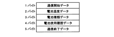
図4に本実施の形態に係る電動工具システム100における通信データの一例を示す。本実施の形態では、電池MCU23は、通信開始データと、電池パック20の電池情報を示す電池情報データと、通信終了データとを含むパルス電圧信号を送信する。通信開始データは、通信データの送信開始を示すデータであり、通信終了データは、通信データの送信終了を示すデータである。電池情報データは、本実施の形態では、電池温度データ、電池種類データ及び電池使用履歴データを含む。電池温度データは、電池組21の電池温度Tを示すデータである。電池種類データは、電池パック20の種別を示すデータである。使用履歴データは、電池パック20の使用履歴(使用回数)を示すデータである。工具MCU14は、1組のパルス電圧信号から、通信開始データ、電池温度データ、電池種類データ、電池使用履歴データ及び通信終了データからなる6バイトの通信データを取得する。
FIG. 4 shows an example of communication data in the electric
ここで、1バイトの通信データには、28=256種類の情報を含めることができる。すなわち、電池温度Tであれば、例えば0℃から255℃までの情報を1℃刻みで伝達することが可能である。一方、二値信号により電池温度を伝達する場合、電池温度Tが基準温度T0未満である通常状態を示す情報と、電池温度Tが基準温度T0以上である高温状態を示す情報との2種類の情報のいずれかを伝達することができるのみであり、詳細な電池温度Tを伝達することはできない。つまり、シリアル通信により送受信された通信データは、二値信号により伝達される情報に比べて詳細な情報、すなわち電池パック20の詳細な状態を伝達可能である。
Here, 2 8 = 256 types of information can be included in 1-byte communication data. That is, when the battery temperature is T, for example, information from 0 ° C. to 255 ° C. can be transmitted in increments of 1 ° C. On the other hand, when transmitting the battery temperature by the binary signal, second information indicating information indicating normal state is lower than the battery temperature T is a reference temperature T 0, the high temperature is the battery temperature T is a reference temperature T 0 or more Only one of the types of information can be transmitted, and the detailed battery temperature T cannot be transmitted. That is, the communication data transmitted / received by serial communication can transmit detailed information, that is, the detailed state of the
図3に戻って、本実施の形態の電動工具システム100では、電池パック20に加えて、電動工具10もパルス電圧信号のシリアル通信による送信が可能である。電動工具10の工具MCU14は、通信モードにおいて、通信開始要求や電池情報要求等の電池パック20に対する要求コマンドを、パルス電圧信号により送信する。工具MCU14は、要求コマンドに対応する数値を選択して、パルス電圧信号を生成し、所定のタイミングで、送信端子14d及び通信端子15cを介して、当該パルス電圧信号を電池パック20へ送信する。電池パック20の電池MCU23は、通信端子25c及び受信端子23fを介して、パルス電圧信号を受信すると、所定の信号処理を行い、要求コマンドを含む通信データを取得する。そして、電池MCU23は、受信した要求コマンドが通信開始要求であった場合、通信許可情報に対応するパルス電圧信号を電動工具10へ送信する。また、受信した要求コマンドが電池情報要求であった場合、電池情報データを含むパルス電圧信号を電動工具10へ送信する。
Returning to FIG. 3, in the electric
続いて、電動工具システム100の動作について、図5及び図6を参照して説明する。図5は、本発明の実施の形態に係る電動工具10(第2の電動工具)の動作を示すフローチャートであり、図6は、本発明の実施の形態に係る電池パック20(第2の電池パック)の動作を示すフローチャートである。
Subsequently, the operation of the electric
まず、電動工具10の動作について、説明する。図5のフローチャートは、電動工具10の端子部15に電池パック20が接続された後、トリガスイッチ13のオンを契機に開始し、トリガスイッチ13のオフにより終了する。
First, the operation of the
トリガスイッチ13がオンされると、電池パック20から工具MCU14への電力供給が開始され、工具MCU14は起動する。工具MCU14は、所定の初期化処理を行った後、端子部15に接続された電池パック20に対し、通信開始要求を送信する(ステップS101)。工具MCU14は、電池パック20へ通信開始要求を送信した後、電池パック20からの通信許可情報の受信を待つ(ステップS102)。
When the
通信許可情報を受信すると(ステップS102:YES)、工具MCU14は、端子部15に接続された電池パックがシリアル通信可能な第2の電池パック20であると判断し、通信モードを開始する(ステップS103)。工具MCU14は、電池パック20へ電池情報要求を送信する(ステップS104)。
When the communication permission information is received (step S102: YES), the
電池パック20から電池情報データを含む通信データ(図4)を受信すると(ステップS105:YES)、工具MCU14は、当該電池情報データに基づいてモータ11の駆動制御を行う通信モード処理を実行する(ステップS106)。通信モード処理の詳細については、後述する。
When the communication data (FIG. 4) including the battery information data is received from the battery pack 20 (step S105: YES), the
電池情報要求の送信から所定時間が経過すると(ステップS107:YES)、工具MCU14は、再度、電池パック20へ電池情報要求を送信する(ステップS104)。そして、電池パック20から受信した電池情報データに基づき、モータ11の駆動制御を行う(ステップS105〜S106)。
When a predetermined time has elapsed since the transmission of the battery information request (step S107: YES), the
このように、工具MCU14は、所定時間毎に電池情報要求を送信し、電池情報データに基づくモータ11の駆動制御を行う(ステップS104〜S106)。 Thus, tool MCU14 transmits a battery information request | requirement for every predetermined time, and performs drive control of the motor 11 based on battery information data (step S104-S106).
電池情報要求の送信後、所定時間が経過しても電池情報データを受信しない場合(ステップS108:YES)、工具MCU14は、モータ11の運転を禁止する(ステップS109)。
If the battery information data is not received even after a predetermined time has elapsed after the transmission of the battery information request (step S108: YES), the
上記のように、シリアル通信可能な電池パック20がシリアル通信可能な電動工具10に接続された場合、電動工具10は、電池パック20から電池情報データを受信して、当該電池情報データに基づくモータ11の駆動制御を行う。
As described above, when the
次に、電池パック20の動作について、説明する。電池パック20は、初期状態において、通常モードで動作する(ステップS201)。電池MCU23は、電池温度T、電池電圧VB及び電流値Iを監視し、電池パック20が通常状態である場合、運転許可信号を出力する。また、電池パック20が警告状態であると判断した場合、運転禁止信号を出力する。
Next, the operation of the
通常モードにおいて(ステップS202:YES)、通信開始要求を受信すると(ステップS203:YES)、電池MCU23は、端子部25に接続された電動工具がシリアル通信可能な第2の電動工具10であると判断し、通常モードから通信モードに制御モードを切り替える(ステップS204)。電池MCU23は、通信開始要求に応じて、通信許可を示す通信許可情報を電動工具10へ送信する(ステップS205)。
In the normal mode (step S202: YES), when a communication start request is received (step S203: YES), the
通信許可情報の送信後、通信モードにおいて(ステップS202:NO)、電池情報要求を受信すると(ステップS206:YES)、電池MCU23は、電池情報データを送信する(ステップS207)。電池MCU23は、図4に示す通信データを含む1組のパルス電圧信号を電動工具10へ送信する。
After the communication permission information is transmitted, in the communication mode (step S202: NO), when the battery information request is received (step S206: YES), the
電池MCU23は、所定時間毎に電動工具10から送信される電池情報要求を受信すると(ステップS206:YES)、電池情報データの送信を行う(ステップS207)。
When the
電池情報要求の受信後、一定時間が経過しても電池情報要求を受信しない場合(ステップS207:NO,ステップS208:YES)、例えば、電動工具10のトリガスイッチ13がオフされた場合や、電動工具10及び電池パック20間の通信に不具合が生じた場合、電池MCU23は、電動工具10の運転を禁止する(ステップS209)。電池MCU23は、通信端子25cを介して運転禁止信号を出力する。
When the battery information request is not received even after a predetermined time has elapsed after receiving the battery information request (step S207: NO, step S208: YES), for example, when the
上記のように、シリアル通信可能な電池パック20がシリアル通信可能な電動工具10に接続された場合、電動工具10からの電池情報要求に応じて、電池情報データが電動工具10へ送信される。
As described above, when the
なお、図6のフローチャートにおいて、電池MCU23は、通常モード及び通信モードのいずれの状態においても、電池温度T、電池電圧VB及び電流値Iを常に監視する。そして、電池パック20が警告状態であると判断すると、運転禁止信号を出力して、電動工具10の運転を禁止する。
In the flowchart of FIG. 6, the battery MCU23, even in any state of the normal mode and the communication mode, to monitor the battery temperature T, a battery voltage V B and the current value I always. When it is determined that the
次に、図5のステップS106の処理について、図7を参照して説明する。図7は、本発明の実施の形態に係る電動工具10における通信モードでの動作の一例を示すフローチャートである。
Next, the process of step S106 in FIG. 5 will be described with reference to FIG. FIG. 7 is a flowchart showing an example of the operation in the communication mode in the
前述したように、電動工具10の工具MCU14は、電池種類データ及び電池使用履歴データに応じた複数の温度閾値を記憶している。例えば、電池パック20を示す電池種類データと、電池パック20の使用履歴(例えば、20回)に対応する電池使用履歴データ(例えば、0〜30回)とに対応して、第1温度閾値T1=60℃、第2温度閾値T2=55℃、第3温度閾値T3=50℃、第4温度閾値T4=45℃が記憶されていた場合を例に、説明を行う。
As described above, the
電動工具10において、工具MCU14は、電池パック20から受信した電池情報データから、電池温度データ、電池種類データ及び電池使用履歴データを取得する(ステップS301)。そして、電池種類データ及び電池使用履歴データに対応して予め記憶されている第1温度閾値T1、第2温度閾値T2、第3温度閾値T3及び第4温度閾値T4を取得する(ステップS301)。工具MCU14は、第1温度閾値T1=60℃、第2温度閾値T2=55℃、第3温度閾値T3=50℃及び第4温度閾値T4=45℃を取得する。
In the
続いて、工具MCU14は、電池温度Tと第1温度閾値T1=60℃とを比較する(ステップS302)。電池温度Tが60℃以上である場合(ステップS302:YES)、工具MCU14は、電池パック20が高温状態に近づいていると判断し、電動工具10の運転を停止する(ステップS307)。工具MCU14は、PWM制御端子14cからの駆動信号の出力を停止して、スイッチング素子12をオフすることにより、モータ11の駆動を停止する。
Subsequently, the
電池温度Tが60℃未満である場合(ステップS302:NO)、工具MCU14は、続いて、電池温度Tと第2温度閾値T2=55℃とを比較する(ステップS303)。電池温度Tが55℃以上である場合(ステップS303:YES)、工具MCU14は、電動工具10の最大出力を最大値の70%以下に制限する(ステップS308)。工具MCU14は、PWM制御端子14cから出力する駆動信号のデューティ比を調整することにより、モータ11の駆動制御を行い、最大出力の制限を行う。
When the battery temperature T is less than 60 ° C. (step S302: NO), the
電池温度Tが55℃未満である場合(ステップS303:NO)、工具MCU14は、続いて、電池温度Tと第3温度閾値T3=50℃とを比較する(ステップS304)。電池温度Tが50℃以上である場合(ステップS304:YES)、工具MCU14は、電動工具10の最大出力を最大値の80%以下に制限する(ステップS309)。
When the battery temperature T is lower than 55 ° C. (step S303: NO), the
電池温度Tが50℃未満である場合(ステップS304:NO)、工具MCU14は、続いて、電池温度Tと第4温度閾値T4=45℃とを比較する(ステップS305)。電池温度Tが45℃以上である場合(ステップS305:YES)、工具MCU14は、電動工具10の最大出力を最大値の90%以下に制限する(ステップS310)。
When the battery temperature T is lower than 50 ° C. (step S304: NO), the
電池温度Tが45℃未満である場合(ステップS305:NO)、工具MCU14は、電動工具10の出力制限を行わず、通常状態で出力を行うべくモータ11の駆動制御を行う(ステップS306)。
When the battery temperature T is lower than 45 ° C. (step S305: NO), the
上記のように、電池パック20の種別及び使用履歴に応じた温度閾値が設定され、当該温度閾値に基づき電池温度Tに応じたモータ11の駆動制御が行われる。
As described above, the temperature threshold corresponding to the type and usage history of the
以上のように、本実施の形態に係る電動工具システム100では、シリアル通信によるデータの送受信が可能な電動工具10にシリアル通信によるデータの送受信が可能な電池パック20が接続された場合、電池パック20の電池温度等のデータを含む電池情報データが、電池パック20から電動工具10へ送信される。したがって、電池温度等、電池パック20の内部状態に応じたモータ11の制御が可能となる。また、電池情報データは、シリアル通信により送受信されるので、電池パック20から電動工具10に詳細な電池情報データを伝達可能となる。そのため、電池パック20の詳細な内部状態に応じて、きめ細やかなモータ11の駆動制御が可能となる。したがって、電池温度が高温になるといきなり電動工具10を停止するのではなく、電池温度の上昇に伴い徐々に出力を制限することにより、作業性を維持しつつ電池パック20の劣化及び短寿命化を抑制可能となる。更に、電池パック20の電池情報データは、電動工具10におけるモータ11の駆動中にも、所定時間毎に電動工具10へ送信されるので、電動工具10の使用中にも、電池パック20の内部状態の変動に応じたモータ11の駆動制御が可能となる。したがって、電池パック20の劣化及び短寿命化を効果的に抑制可能となる。
As described above, in the
ところで、電動工具10は、シリアル通信可能な電池パック20のみならず、シリアル通信が不可能な第1の電池パックをも接続して使用可能である。そこで、電動工具10を第1の電池パックに接続した場合について、図8を参照して説明する。図8は、本発明の実施の形態に係る電動工具10を含む電動工具システム200の電気的構成を示す回路図である。なお、図1と同一の構成要素については、同一の符号を付して、その説明を省略する。
By the way, the
電動工具システム200において、電動工具10の端子部15には、電池パック30が接続されている。電池パック30は、信号の出力のみが可能な第1の電池パックであり、図8に示されるように、電池組21、シャント抵抗22、電池MCU33、サーミスタ24、プラス端子25a、マイナス端子25b及び信号端子35cを備えている。
In the electric
電池MCU33は、マイクロコンピュータであり、電池組21に並列に接続され、電池組21の電池温度Tと、電池組21の電池電圧VBと、電池組21から電動工具10へ流れる電流値Iとを監視する機能を有する。また、電池MCU23には、図8に示されるように、電源端子23a、GND端子23b、電流検知端子23c、温度検知端子23d及び出力ポート33eが設けられる。
The
出力ポート33eは、抵抗36を介して信号端子35cに接続される。電池MCU33は、出力ポート33e及び信号端子35cを介して、図2に示される運転許可信号及び運転禁止信号のいずれかを出力する。電池MCU33は、電池温度T、電池電圧VB及び電流値Iに基づき、電池パック30が通常状態であるか或いは警告状態であるかを判断し、判断結果に応じて信号の出力を行う。
The
プラス端子25a、マイナス端子25b及び信号端子35cは、電池パック30の電動工具との接続面(不図示)に向けられ、端子部35を構成する。信号端子35cは、電池側信号端子の一例であり、二値信号の出力が可能な端子である。
The plus terminal 25 a, the
電動工具10に電池パック30が接続される場合、電池パック30のプラス端子25a、マイナス端子25b及び信号端子35cが、それぞれ、電動工具10のプラス端子15a、マイナス端子15b及び通信端子15cに接続される。このように、各端子が接続された状態で、電動工具10及び電池パック30は電気的に接続され、電動工具10は、電池パック30から電力の供給を受けることが可能となるとともに、電池パック30からの信号の入力が可能となる。
When the
続いて、第1の電池パック30が接続された場合の電動工具10の動作について、図5を参照して説明する。
Next, the operation of the
電動工具10において、トリガスイッチ13がオンされると、工具MCU14は起動し、電池パック30に対し通信開始要求を送信する(ステップS101)。工具MCU14は、通信開始要求の送信後、電池パック30からの通信許可情報の受信を待つ(ステップS102)。
When the
電池パック30の信号端子35cは、信号の入力を受け付けず、電池パック30は、通信許可情報を送信しない。そのため、電動工具10の工具MCU14は、通信許可情報の送信から所定時間が経過しても、通信許可情報を受信しない(ステップS102:NO,ステップS110:YES)。この場合、工具MCU14は、端子部15に接続された電池パックが、信号の出力のみを行いシリアル通信を行わない第1の電池パック30であると判断し、通常モードを開始する(ステップS111)。工具MCU14は、通常モードにおいて、信号端子35c及び通信端子15cを介して運転許可信号が入力されると、モータ11を回転駆動し、運転禁止信号が入力されると、モータ11の回転駆動を停止する。
The
上記のように、シリアル通信が不可能な第1の電池パック30がシリアル通信可能な第2の電動工具10に接続された場合、電動工具10は、電池パック30の種別を判断して、電池情報データによらないモータ11の駆動制御を行う。
As described above, when the
以上のように、本実施の形態に係る電動工具10によれば、シリアル通信によるデータの送受信が可能な第2の電池パック20のみならず、二値信号の出力のみが可能な第1の電池パック30をも接続可能であるため、互換性の確保が可能となる。また、第1の電池パック20からの信号の入力及びシリアル通信によるデータの送受信のいずれも、一の通信端子15cを介して行われるので、端子数を増やす必要が無く、コストの抑制が可能となる。
As described above, according to the
また、本実施の形態に係る第2の電池パック20は、同様に、シリアル通信可能な第2の電動工具10のみならず、シリアル通信が不可能な第1の電動工具にも接続して使用可能である。そこで、第2の電池パック20を第1の電動工具に接続した場合について、図9を参照して説明する。図9は、本発明の実施の形態に係る電池パック20を含む電動工具システム300の電気的構成を示す回路図である。なお、図1と同一の構成要素については、同一の符号を付して、その説明を省略する。
Similarly, the
電動工具システム300において、電池パック20の端子部25は、電動工具40に接続される。電動工具40は、信号の入力のみが可能な第1の電動工具であり、図9に示されるように、モータ11、スイッチング素子12、トリガスイッチ13、工具MCU44、プラス端子15a、マイナス端子15b及び信号端子45cを備えている。
In the electric
工具MCU44は、マイクロコンピュータであり、モータ11の駆動を制御する機能を有する。また、工具MCU44には、図9に示されるように、電源端子14a、GND端子14b、PWM制御端子14c及び入力ポート44eが設けられる。
The
入力ポート44eは、抵抗47を介して信号端子45cに接続される。工具MCU44には、信号端子45c及び入力ポート44eを介して、図2に示される運転許可信号及び運転禁止信号のいずれかが入力される。工具MCU44は、運転許可信号が入力されるとモータ11を駆動し、運転禁止信号が入力されるとモータ11の駆動を停止する。
The
プラス端子15a、マイナス端子15b及び信号端子45cは、電動工具40の電池パックとの接続面(不図示)に設けられ、端子部45を構成する。信号端子45cは、工具側信号端子の一例であり、二値信号の入力が可能な端子である。
The plus terminal 15 a, the
電動工具40に電池パック20が接続される場合、電池パック20のプラス端子25a、マイナス端子25b及び通信端子25cが、それぞれ、電動工具40のプラス端子15a、マイナス端子15b及び信号端子45cに接続される。このように、各端子が接続された状態で、電動工具40及び電池パック20は電気的に接続され、電動工具40は、電池パック20から電力の供給を受けることが可能となるとともに、電池パック20からの信号の入力が可能となる。
When the
続いて、既存の電動工具40が接続された場合の電池パック20の動作について、図6を参照して説明する。
Next, the operation of the
電池パック20は、初期状態において、通常モードで動作する(ステップS201)。電池MCU23は、電池温度T、電池電圧VB及び電流値Iを監視し、電池パック20が通常状態である場合、運転許可信号を出力する。また、電池パック20が警告状態であると判断した場合、運転禁止信号を出力する。
The
通常モードにおいて(ステップS202:YES)、通信開始要求の受信が無い場合(ステップS203:NO)、電池MCU23は、端子部25が接続された電動工具が、信号の入力のみを行いシリアル通信を行わない第1の電動工具40であると判断し、通常モードを継続する(ステップS202:YES)。電池MCU23は、電池温度T、電池電圧VB及び電流値Iを監視し、電池パック20の状態に応じて、運転許可信号及び運転禁止信号のいずれかを出力する。
In the normal mode (step S202: YES), when no communication start request is received (step S203: NO), the
上記のように、シリアル通信が不可能な第1の電動工具40にシリアル通信可能な第2の電池パック20が接続された場合、電池パック20は、電動工具40の種別を判断して、二値信号の出力のみを行う。
As described above, when the
以上のように、本実施の形態に係る電池パック20によれば、シリアル通信によるデータの送受信が可能な第2の電動工具10のみならず、二値信号の入力のみが可能な第1の電動工具40にも接続可能であるため、互換性の確保が可能となる。また、第1の電動工具40への信号の出力及びシリアル通信によるデータの送受信のいずれも、一の通信端子25cを介して行われるので、端子数を増やす必要が無く、コストの抑制が可能となる。
As described above, according to the
以上、本発明を実施の形態に基づき説明したが、本発明は上述の実施の形態に限定されるものではなく、その趣旨を逸脱しない範囲内で、種々の変更や改良が可能である。 Although the present invention has been described based on the embodiments, the present invention is not limited to the above-described embodiments, and various modifications and improvements can be made without departing from the spirit of the present invention.
例えば、上記した電動工具10は、通信モードでのモータ11の駆動制御時に使用するデータとして、電池種類データ及び電池使用履歴データに応じて、4つの温度閾値を記憶しているが、本発明はこれに限定されない。温度閾値の数は4つに限定されず、また、複数の温度閾値に加えて、電流閾値や電池電圧閾値等、複数種の閾値を、それぞれ一又は複数ずつ記憶しても良い。更に、各閾値に対応して、出力制限の数値(70%、80%、90%等)を個別に記憶しても良い。
For example, the
また、電池パック20から送信される電池情報データの一例として、電池温度データ、電池種類データ及び電子使用履歴データを挙げたが、本発明はこれに限定されない。例えば、電流値Iを示すデータを電池情報データに含めても良い。この場合、電動工具10において、温度閾値に加えて、電流閾値を記憶し、電流値Iの変動に応じて出力制限を行う構成とすることが可能となる。
Moreover, although battery temperature data, battery type data, and electronic use history data were mentioned as an example of the battery information data transmitted from the
10 電動工具
11 モータ
14 工具MCU
14d 送信端子
14e 受信端子
15c 通信端子
20 電池パック
21 電池組
23 電池MCU
23e 送信端子
23f 受信端子
25c 通信端子
100,200,300 電動工具システム
10 Electric tool 11
Claims (16)
モータ停止信号を出力可能な電池側信号端子を有する第1の電池パック及びシリアル通信によるデータの送受信が可能な電池側通信端子を有する第2の電池パックのいずれをも接続可能な接続手段と、
前記接続手段に接続された電池パックの種別に応じて、前記モータの制御を行う制御手段と、を備え、
前記接続手段は、前記電池側信号端子及び前記電池側通信端子のいずれにも接続可能且つ前記モータ停止信号の入力及びシリアル通信によるデータの送受信が可能な工具側通信端子を有し、
前記制御手段は、前記接続手段に前記第2の電池パックが接続された場合、前記電池側通信端子及び前記工具側通信端子を介して受信されたデータに基づき、前記モータの制御を行うことを特徴とする電動工具。 A motor,
Connection means capable of connecting both the first battery pack having a battery-side signal terminal capable of outputting a motor stop signal and the second battery pack having a battery-side communication terminal capable of transmitting and receiving data by serial communication;
Control means for controlling the motor according to the type of the battery pack connected to the connection means,
The connection means has a tool-side communication terminal that can be connected to both the battery-side signal terminal and the battery-side communication terminal, and that can input and output the motor stop signal and send and receive data by serial communication.
When the second battery pack is connected to the connection means, the control means controls the motor based on data received via the battery side communication terminal and the tool side communication terminal. A featured electric tool.
前記工具側通信端子は、前記送信端子及び前記受信端子に接続されることを特徴とする請求項1乃至5のいずれか1項に記載の電動工具。 The control means is a microcomputer having a transmission terminal and a reception terminal,
The power tool according to any one of claims 1 to 5, wherein the tool side communication terminal is connected to the transmission terminal and the reception terminal.
信号を入力可能な工具側信号端子を有する第1の電動工具及びシリアル通信によるデータの送受信が可能な工具側通信端子を有する第2の電動工具のいずれをも接続可能な接続手段と、
前記接続手段に接続された電動工具の種別に応じて、前記二次電池の放電制御を行う制御手段と、を備え、
前記接続手段は、前記工具側信号端子及び前記工具側通信端子のいずれにも接続可能且つ信号の出力及びシリアル通信によるデータの送受信が可能な電池側通信端子を有し、
前記制御手段は、前記接続手段に前記第2の電動工具が接続された場合、該第2の電動工具に、前記電池側通信端子を介して電池情報を送信することを特徴とする電池パック。 At least one secondary battery;
A connecting means capable of connecting both the first electric tool having a tool-side signal terminal capable of inputting a signal and the second electric tool having a tool-side communication terminal capable of transmitting and receiving data by serial communication;
Control means for performing discharge control of the secondary battery according to the type of the electric tool connected to the connection means,
The connection means has a battery-side communication terminal that can be connected to both the tool-side signal terminal and the tool-side communication terminal and can transmit and receive data by signal output and serial communication,
The control means, when the second power tool is connected to the connection means, transmits battery information to the second power tool via the battery side communication terminal.
前記電池側通信端子は、前記送信端子及び前記受信端子に接続されることを特徴とする請求項7乃至10のいずれか1項に記載の電池パック。 The control means is a microcomputer having a transmission terminal and a reception terminal,
The battery pack according to claim 7, wherein the battery-side communication terminal is connected to the transmission terminal and the reception terminal.
少なくとも一つの二次電池を有し、前記モータの駆動源となる電池パックと、を備える電動工具システムであって、
前記電池パックは、
シリアル通信によるデータの送受信が可能な電池側通信端子と、
前記二次電池の放電制御を行う電池側制御手段と、を備え、
前記電動工具は、
シリアル通信によるデータの送受信が可能であり、前記電池側通信端子に接続し、前記電池パックに電池情報要求を送信する工具側通信端子と、
前記モータの制御を行う工具側制御手段と、を備え、
前記電池側制御手段は、前記電池側通信端子を介して前記電池情報要求を受信すると、該電池側通信端子を介して電池情報を送信し、
前記工具側制御手段は、前記工具側通信端子を介して前記電池情報を受信すると、該電池情報に基づき前記モータの制御を行うことを特徴とする電動工具システム。 An electric tool having a motor;
A battery pack comprising at least one secondary battery and serving as a drive source for the motor,
The battery pack is
Battery side communication terminal that can send and receive data by serial communication,
Battery side control means for performing discharge control of the secondary battery,
The electric tool is
Transmission and reception of data by serial communication is possible, connected to the battery side communication terminal, a tool side communication terminal that transmits a battery information request to the battery pack,
Tool-side control means for controlling the motor,
When the battery-side control means receives the battery information request via the battery-side communication terminal, the battery-side control means transmits battery information via the battery-side communication terminal,
The tool-side control means, when receiving the battery information via the tool-side communication terminal, controls the motor based on the battery information.
前記工具側通信端子は、前記工具側送信端子及び前記工具側受信端子に接続されることを特徴とする請求項12乃至14のいずれか1項に記載の電動工具システム。 The tool side control means is a microcomputer having a tool side transmission terminal and a tool side reception terminal,
The power tool system according to any one of claims 12 to 14, wherein the tool side communication terminal is connected to the tool side transmission terminal and the tool side reception terminal.
前記電池側通信端子は、前記電池側送信端子及び前記電池側受信端子に接続されることを特徴とする請求項12乃至15のいずれか1項に記載の電動工具システム。
The battery side control means is a microcomputer having a battery side transmission terminal and a battery side reception terminal,
The power tool system according to any one of claims 12 to 15, wherein the battery side communication terminal is connected to the battery side transmission terminal and the battery side reception terminal.
Priority Applications (1)
| Application Number | Priority Date | Filing Date | Title |
|---|---|---|---|
| JP2016025294A JP2017140686A (en) | 2016-02-12 | 2016-02-12 | Electric power tool, battery pack, and electrically-driven tool system |
Applications Claiming Priority (1)
| Application Number | Priority Date | Filing Date | Title |
|---|---|---|---|
| JP2016025294A JP2017140686A (en) | 2016-02-12 | 2016-02-12 | Electric power tool, battery pack, and electrically-driven tool system |
Publications (1)
| Publication Number | Publication Date |
|---|---|
| JP2017140686A true JP2017140686A (en) | 2017-08-17 |
Family
ID=59628201
Family Applications (1)
| Application Number | Title | Priority Date | Filing Date |
|---|---|---|---|
| JP2016025294A Pending JP2017140686A (en) | 2016-02-12 | 2016-02-12 | Electric power tool, battery pack, and electrically-driven tool system |
Country Status (1)
| Country | Link |
|---|---|
| JP (1) | JP2017140686A (en) |
Cited By (4)
| Publication number | Priority date | Publication date | Assignee | Title |
|---|---|---|---|---|
| JP2019072823A (en) * | 2017-10-18 | 2019-05-16 | 株式会社マキタ | Electric operating machine |
| EP3748804A1 (en) | 2019-06-04 | 2020-12-09 | Makita Corporation | Battery-connected system, battery pack, electric work machine, and charger |
| WO2023151553A1 (en) * | 2022-02-08 | 2023-08-17 | 格力博(江苏)股份有限公司 | Data interaction method and system |
| US11979049B2 (en) | 2018-09-14 | 2024-05-07 | Makita Corporation | Electric work machine |
-
2016
- 2016-02-12 JP JP2016025294A patent/JP2017140686A/en active Pending
Cited By (5)
| Publication number | Priority date | Publication date | Assignee | Title |
|---|---|---|---|---|
| JP2019072823A (en) * | 2017-10-18 | 2019-05-16 | 株式会社マキタ | Electric operating machine |
| US11979049B2 (en) | 2018-09-14 | 2024-05-07 | Makita Corporation | Electric work machine |
| EP3748804A1 (en) | 2019-06-04 | 2020-12-09 | Makita Corporation | Battery-connected system, battery pack, electric work machine, and charger |
| US11811249B2 (en) | 2019-06-04 | 2023-11-07 | Makita Corporation | Battery-powered system, battery pack, electric work machine, and charger |
| WO2023151553A1 (en) * | 2022-02-08 | 2023-08-17 | 格力博(江苏)股份有限公司 | Data interaction method and system |
Similar Documents
| Publication | Publication Date | Title |
|---|---|---|
| JP7118006B2 (en) | Battery management system | |
| US9859548B2 (en) | Shared control of thermistor and dual purpose thermistor line | |
| US7119516B2 (en) | Cordless power tool with tool identification circuitry | |
| KR101696160B1 (en) | Apparatus, system and method for preventing damage of battery rack using voltage measurement | |
| US9768625B2 (en) | Battery pack, and method for controlling the same | |
| US9225182B2 (en) | Charge controller with protective function and battery pack | |
| US11637433B2 (en) | Battery pack and electrical apparatus | |
| JP4936227B2 (en) | Battery pack and electric tool using the battery pack | |
| US11450895B2 (en) | Electric tool and method for supplying power to electric tool | |
| JP4852300B2 (en) | Battery pack | |
| JP5260999B2 (en) | Battery pack | |
| KR20090126098A (en) | Battery pack and method of charge thereof | |
| JP2007273241A (en) | Lithium battery pack | |
| EP2565661A1 (en) | Motor device and power tool | |
| JP2015196196A (en) | Electric power tool | |
| JP2017140686A (en) | Electric power tool, battery pack, and electrically-driven tool system | |
| JP2017225345A (en) | Power supply device | |
| JP5505678B2 (en) | Battery pack and electric tool using the battery pack | |
| JP2016103937A (en) | Battery pack | |
| US20050052159A1 (en) | Method and apparatus for overcharge protection using analog overvoltage detection | |
| KR101744374B1 (en) | Apparatus and method for preventing battery using protective circuit | |
| JP7192877B2 (en) | electric equipment system | |
| JP2015173568A (en) | battery protection circuit and battery pack | |
| JP7240994B2 (en) | Battery pack and charging system | |
| JPWO2016136499A1 (en) | Electric tool |