EP2565661A1 - Motor device and power tool - Google Patents
Motor device and power tool Download PDFInfo
- Publication number
- EP2565661A1 EP2565661A1 EP11774788A EP11774788A EP2565661A1 EP 2565661 A1 EP2565661 A1 EP 2565661A1 EP 11774788 A EP11774788 A EP 11774788A EP 11774788 A EP11774788 A EP 11774788A EP 2565661 A1 EP2565661 A1 EP 2565661A1
- Authority
- EP
- European Patent Office
- Prior art keywords
- determination
- voltage
- rechargeable battery
- temperature
- unit
- Prior art date
- Legal status (The legal status is an assumption and is not a legal conclusion. Google has not performed a legal analysis and makes no representation as to the accuracy of the status listed.)
- Granted
Links
Images


Classifications
-
- G—PHYSICS
- G01—MEASURING; TESTING
- G01R—MEASURING ELECTRIC VARIABLES; MEASURING MAGNETIC VARIABLES
- G01R19/00—Arrangements for measuring currents or voltages or for indicating presence or sign thereof
- G01R19/165—Indicating that current or voltage is either above or below a predetermined value or within or outside a predetermined range of values
- G01R19/16533—Indicating that current or voltage is either above or below a predetermined value or within or outside a predetermined range of values characterised by the application
- G01R19/16538—Indicating that current or voltage is either above or below a predetermined value or within or outside a predetermined range of values characterised by the application in AC or DC supplies
- G01R19/16542—Indicating that current or voltage is either above or below a predetermined value or within or outside a predetermined range of values characterised by the application in AC or DC supplies for batteries
-
- H—ELECTRICITY
- H01—ELECTRIC ELEMENTS
- H01M—PROCESSES OR MEANS, e.g. BATTERIES, FOR THE DIRECT CONVERSION OF CHEMICAL ENERGY INTO ELECTRICAL ENERGY
- H01M10/00—Secondary cells; Manufacture thereof
- H01M10/42—Methods or arrangements for servicing or maintenance of secondary cells or secondary half-cells
- H01M10/48—Accumulators combined with arrangements for measuring, testing or indicating the condition of cells, e.g. the level or density of the electrolyte
- H01M10/486—Accumulators combined with arrangements for measuring, testing or indicating the condition of cells, e.g. the level or density of the electrolyte for measuring temperature
-
- H—ELECTRICITY
- H02—GENERATION; CONVERSION OR DISTRIBUTION OF ELECTRIC POWER
- H02H—EMERGENCY PROTECTIVE CIRCUIT ARRANGEMENTS
- H02H7/00—Emergency protective circuit arrangements specially adapted for specific types of electric machines or apparatus or for sectionalised protection of cable or line systems, and effecting automatic switching in the event of an undesired change from normal working conditions
- H02H7/18—Emergency protective circuit arrangements specially adapted for specific types of electric machines or apparatus or for sectionalised protection of cable or line systems, and effecting automatic switching in the event of an undesired change from normal working conditions for batteries; for accumulators
-
- H—ELECTRICITY
- H02—GENERATION; CONVERSION OR DISTRIBUTION OF ELECTRIC POWER
- H02P—CONTROL OR REGULATION OF ELECTRIC MOTORS, ELECTRIC GENERATORS OR DYNAMO-ELECTRIC CONVERTERS; CONTROLLING TRANSFORMERS, REACTORS OR CHOKE COILS
- H02P29/00—Arrangements for regulating or controlling electric motors, appropriate for both AC and DC motors
- H02P29/02—Providing protection against overload without automatic interruption of supply
- H02P29/024—Detecting a fault condition, e.g. short circuit, locked rotor, open circuit or loss of load
- H02P29/0241—Detecting a fault condition, e.g. short circuit, locked rotor, open circuit or loss of load the fault being an overvoltage
-
- H—ELECTRICITY
- H02—GENERATION; CONVERSION OR DISTRIBUTION OF ELECTRIC POWER
- H02H—EMERGENCY PROTECTIVE CIRCUIT ARRANGEMENTS
- H02H3/00—Emergency protective circuit arrangements for automatic disconnection directly responsive to an undesired change from normal electric working condition with or without subsequent reconnection ; integrated protection
- H02H3/006—Calibration or setting of parameters
-
- H—ELECTRICITY
- H02—GENERATION; CONVERSION OR DISTRIBUTION OF ELECTRIC POWER
- H02H—EMERGENCY PROTECTIVE CIRCUIT ARRANGEMENTS
- H02H3/00—Emergency protective circuit arrangements for automatic disconnection directly responsive to an undesired change from normal electric working condition with or without subsequent reconnection ; integrated protection
- H02H3/24—Emergency protective circuit arrangements for automatic disconnection directly responsive to an undesired change from normal electric working condition with or without subsequent reconnection ; integrated protection responsive to undervoltage or no-voltage
-
- H—ELECTRICITY
- H02—GENERATION; CONVERSION OR DISTRIBUTION OF ELECTRIC POWER
- H02J—CIRCUIT ARRANGEMENTS OR SYSTEMS FOR SUPPLYING OR DISTRIBUTING ELECTRIC POWER; SYSTEMS FOR STORING ELECTRIC ENERGY
- H02J7/00—Circuit arrangements for charging or depolarising batteries or for supplying loads from batteries
- H02J7/0029—Circuit arrangements for charging or depolarising batteries or for supplying loads from batteries with safety or protection devices or circuits
- H02J7/00306—Overdischarge protection
-
- Y—GENERAL TAGGING OF NEW TECHNOLOGICAL DEVELOPMENTS; GENERAL TAGGING OF CROSS-SECTIONAL TECHNOLOGIES SPANNING OVER SEVERAL SECTIONS OF THE IPC; TECHNICAL SUBJECTS COVERED BY FORMER USPC CROSS-REFERENCE ART COLLECTIONS [XRACs] AND DIGESTS
- Y02—TECHNOLOGIES OR APPLICATIONS FOR MITIGATION OR ADAPTATION AGAINST CLIMATE CHANGE
- Y02E—REDUCTION OF GREENHOUSE GAS [GHG] EMISSIONS, RELATED TO ENERGY GENERATION, TRANSMISSION OR DISTRIBUTION
- Y02E60/00—Enabling technologies; Technologies with a potential or indirect contribution to GHG emissions mitigation
- Y02E60/10—Energy storage using batteries
Definitions
- the present invention relates to a motor device for a power tool or the like that uses a rechargeable battery as a drive power supply for an electric motor.
- a power tool or the like proposed in the prior art is driven by an electric motor supplied with power from a rechargeable battery and includes, in regard to protection of the rechargeable battery, a means for detecting the voltage of a battery cell of the rechargeable battery and a means for determining an abnormality (over-discharge) when the voltage value becomes less than a determination value and controlling the supply of power to the motor, that is, stopping the operation of the power tool (for example, refer to patent document 1).
- the voltage decrease amount in the voltage of the rechargeable battery When the discharge current increases, the decrease amount in the voltage of the rechargeable battery also increases. Generally, the voltage decrease amount is determined by the product of an internal resistor or wire resistor and the discharge current. However, temperature affects and varies the resistance. Accordingly, even when the same discharge current is used for an operation, the voltage decrease amount that occurs in the rechargeable battery varies in accordance with changes in the resistance of an internal resistor or the like resulting from changes in the temperature of the usage environment. Even when the power tool may be operated under normal temperatures, depending on the present usage environment temperature, the supply of power to the motor may be stopped, that is, the control for stopping the operation of the power tool may be implemented at an early stage. This narrows the operable range of the power tool.
- One aspect of the present invention is a motor device including an electric motor operated when supplied with power from a rechargeable battery.
- a voltage detection unit detects voltage of the rechargeable battery.
- a determination unit performs an abnormality determination based on a comparison of the voltage of the rechargeable battery, which is detected by the voltage detection unit, and a determination value.
- a control unit controls the operation of the electric motor in accordance with the determination result of the determination unit.
- a temperature detection unit detects the usage environment temperature. The determination unit changes the determination value in accordance with the temperature detected by the temperature detection unit and performs the abnormality determination based on the changed determination value. As a result, even when the usage environment temperature changes, the operable range of the motor device can be maintained in a preferred manner.
- Fig. 1 shows a power tool 10 serving as a motor device in the present embodiment.
- the power tool 10 is, for example, a drill driver or a disk grinder, and includes a power tool body 11, which uses an electric motor M as a drive source, and a battery pack 21, which is attached in a removable manner to the power tool body 11.
- the power tool body 11 includes power terminals 11a and 11 b, which are supplied with power from the battery pack 21, and signal terminals 11c and 11d, which receive various detection signals from the battery pack 21.
- the electric motor M includes a positive terminal, which is connected via an operation switch 12 to the power terminal 11a, and a negative terminal, which is connected via a motor drive circuit 13 to the power terminal 11b.
- An electronic switch 14, such as a transistor, and a power supply circuit 15 are connected in parallel to the operation switch 12.
- the control circuit 16 includes a positive terminal, which is connected via the power supply circuit 15 and the electronic switch 14 to the power terminal 11a, and a negative terminal, which is connected to the power terminal 11 b.
- the operation switch 12 When the operation switch 12 is activated, power is supplied from the battery pack 21 via the power terminals 11a and 11b to the motor M.
- the activation of the operation switch 12 sends a switch signal to the control circuit 16 and the electronic switch 14.
- the switch signal activates the electronic switch 14.
- the electronic switch 14 When the electronic switch 14 is activated, power is supplied from the battery pack 21 to the power supply circuit 15, which supplies operation power for the control circuit 16.
- the control circuit 16 becomes operational when supplied with operational power from the power supply circuit 15 and controls rotation produced by the motor M with the motor drive circuit 13. Even when the operation switch 12 is deactivated, the control circuit 16 may control the electronic switch 14 to perform a timer operation so that the supply of operational power is continued for a predetermined time.
- a voltage detection circuit 17 is arranged between the power terminals 11a and 11 b to detect the voltage between the terminals, namely, the voltage of the battery pack 21 (rechargeable battery 22) at the body 11.
- the voltage detection circuit 17 is one example of a voltage detection unit.
- the voltage value (detected voltage) detected by the voltage detection circuit 17 is provided as a voltage detection signal to the control circuit 16.
- the control circuit 16 is provided with a voltage detection signal from a voltage detection circuit 23 in the battery pack 21 and a temperature detection signal from a temperature detection element 24 in the battery pack 21 via signal terminals 11c and 11 d.
- the voltage detection circuit 23 is one example of a voltage detection unit.
- the battery pack 21 is attached in a removable manner to the power tool body 11 and includes power terminals 21a and 21 b and signal terminals 21c and 21d respectively corresponding to the power terminals 11 a and 11 b and signal terminals 11 c and 11d of the power tool body 11.
- the terminals 11 a to 11d are electrically connected to the terminals 21 a to 21 d, respectively. This allows for the power tool body 11 to be supplied with power and provided with various types of detection signals.
- the battery pack 21 is also attached in a removable manner to a charger (not shown) and charged by the charger.
- the battery pack 21 accommodates the rechargeable battery 22, which is formed by a plurality of battery cells, such as lithium ion batteries.
- the rechargeable battery 22 includes a positive terminal, which is connected to the power terminal 21 a, and a negative terminal, which is connected to the power terminal 21 b.
- the voltage detection circuit 23 of the battery pack 21 is operated when supplied with power from the rechargeable battery 22, detects the voltage value of each battery cell in the rechargeable battery 22, and detects the total voltage (voltage at the two terminals) of the rechargeable battery 22.
- the voltage value detected by the voltage detection circuit 23 is provided as a voltage detection signal via the terminals 21c and 11c to the control circuit 16 of the power tool body 11.
- the battery pack 21 includes the temperature detection element 24, which is a thermistor or the like.
- the temperature detection element 24 detects the usage environment temperature in the battery pack 21.
- the temperature detected by the temperature detection element 24 is provided as a temperature detection signal via the terminals 21 d and 11d to the control circuit 16 of the power tool body 11.
- the control circuit 16 recognizes the voltage of the rechargeable battery 22 based on the voltage detection signals from the voltage detection circuits 17 and 23. During use of the power tool 10 (operation of the motor M), the control circuit 16 detects an over-discharge abnormality in the rechargeable battery 22 from the detected voltage value of the rechargeable battery 22. When determining that an over-discharge abnormality is occurring in the rechargeable battery 22, the motor drive circuit 13 stops supplying power to the electric motor M from the rechargeable battery 22. In this manner, the operation of the power tool 10 is automatically stopped when the rechargeable battery 22 includes an over-discharge abnormality. Further, the control circuit 16 recognizes the usage environment temperature based on the temperature detection signal from the temperature detection element 24 and switches the control process in accordance with the usage environment temperature.
- the control circuit 16 is one example of a determination unit and a control unit.
- Fig. 2 shows the voltage decrease amount of the rechargeable battery 22 (change in the resistance of an internal resistor or the like) with respect to changes in the usage environment temperature.
- T°C e.g. 10°C
- the resistance of the internal resistor in the rechargeable battery 22 is small, and the voltage decrease amount is small.
- the usage environment temperature is in a low temperature range that is less than or equal to T°C, as the temperature decreases, the resistance of the internal resistance or the like of the rechargeable battery 22 greatly increases and the voltage decrease amount also greatly increases.
- the control circuit 16 performs an over-discharge abnormality determination, if the determination value used as a determination reference is fixed, there would be a tendency of an abnormal over-discharge being determined when the usage environment temperature is less than or equal to T°C. This would narrow the operational range of the power tool 10.
- the control circuit 16 of the present embodiment switches the determination value (determination reference) when performing abnormal over-discharge determinations.
- a standard determination value V1 is used when the usage environment temperature is in a range higher than T°C (e.g., 10°C), and a determination value V2, which is lower than the standard determination value V1, is used when the usage environment temperature is in a low temperature range that is less than or equal to T°C (e.g., 10°C).
- the standard determination value V1 is set to, for example, 11 V in contrast with the rated voltage of the rechargeable battery 22 that is 14 V.
- the determination value V2 is set to, for example, 10 V.
- the change amount of the voltage decrease of the rechargeable battery 22 is greatly affected by the temperature.
- the determination value is changed to the lower determination value V2. This prevents the supply of power to the electric motor M from being stopped. That is, the control for stopping the operation of the power tool 10 is prevented from being implemented at an early stage. As a result, even in the low temperature range in which the usage environment temperature is T°C or less, a wide operational range may be ensured for the power tool 10.
- the control circuit 16 of the present embodiment performs an over-charge abnormality determination in a state immediately before the electric motor M is operated and immediately after the operation switch 12 is operated. That is, the control circuit 16 performs an initial determination of an over-discharge abnormality in a state immediately before the rechargeable battery 22 generates discharge current. In a state immediately before the electric motor M is operated, the rechargeable battery 22 does not generate discharge current. Thus, there is no voltage decrease in the rechargeable battery 22.
- the control circuit 16 determines an over-discharge abnormality with the determination value V1, which is higher than the determination value V2. In this manner, when there is no temperature-dependent voltage decrease, the determination value V1, which is generally irrelevant to the temperature, is used to accurately perform an over-discharge abnormality determination.
- the control circuit 16 performs over-discharge abnormality determination in predetermined cycles.
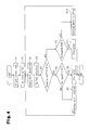
- the control circuit 16 of the present invention performs processing in accordance with the flowchart shown in Fig. 4 .
- step S1 the attachment state of the battery pack 21 is detected.
- step S2 an activation operation of the operation switch 12 is detected.
- step S3 the usage environment temperature is detected.
- step S4 the voltage of the rechargeable battery 22 is detected.
- step S5 the control circuit 16 determines whether or not the detected temperature is higher than T°C (e.g., 10°C). When the temperature is higher than T°C, step S6 is processed. In step S6, the control circuit 16 compares the detected voltage of the rechargeable battery 22 with the determination value V1 (e.g., 11 V) to perform an over-discharge abnormality determination. When the voltage of the rechargeable battery 22 is higher than the determination value V1, that is, when an over-discharge abnormality is not occurring, step S7 is processed. In step S7, the control circuit 16 continues to produce rotation with the electric motor M and continues to operate the power tool 10.
- T°C e.g. 10°C
- step S6 when the voltage of the rechargeable battery 22 is less than or equal to the determination value V1, that is, when an over-discharge abnormality is occurring, step S8 is processed.
- step S8 the control circuit 16 stops supplying power to the electric motor M and stops operating the electric motor M. This stops the operation of the power tool 10.
- step S5 when the value of the temperature is less than or equal to T°C and in the low temperature range, step S9 is processed.
- the control circuit 16 compares the detected voltage of the rechargeable battery 22 with the determination value V2 (e.g., 10V) to determine an over-discharge abnormality.
- V2 e.g., 10V
- step S10 the electric motor M continues to produce rotation, and the power tool 10 continues to operate.
- step S9 when the voltage of the rechargeable battery 22 is less than or equal to the determination value, that is, when an over-discharge abnormality is occurring, step S11 is processed.
- step S11 the supply of power to the electric motor M is stopped to stop the operation of the electric motor M and stop the operation of the power tool 10.
- the above embodiment uses the two determination values V1 and V2 for the over-discharge determination (abnormality determination) of the rechargeable battery 22.
- three or more determination values may be used.
- a determination value that varies linearly in accordance with changes in the usage environment temperature may be used.
- control circuit 16 determines the voltage of the rechargeable battery 22 based on voltage detection signals from the voltage detection circuits 17 and 23.
- the voltage of the rechargeable battery 22 may be determined with only the detection signal from the voltage detection circuit 23.
- the temperature detection element 24 in the battery pack 21 detects the usage environment temperature.
- the power tool body 11 may perform the temperature detection.
- the above embodiment is applied to the power tool 10, which serves as a motor device.
- the above embodiment may be applied to other motor devices.
Abstract
Description
- The present invention relates to a motor device for a power tool or the like that uses a rechargeable battery as a drive power supply for an electric motor.
- A power tool or the like proposed in the prior art is driven by an electric motor supplied with power from a rechargeable battery and includes, in regard to protection of the rechargeable battery, a means for detecting the voltage of a battery cell of the rechargeable battery and a means for determining an abnormality (over-discharge) when the voltage value becomes less than a determination value and controlling the supply of power to the motor, that is, stopping the operation of the power tool (for example, refer to patent document 1).
-
- Patent Document 1: Japanese Laid-Open Patent Publication No.
10-27630 - When the discharge current increases, the decrease amount in the voltage of the rechargeable battery also increases. Generally, the voltage decrease amount is determined by the product of an internal resistor or wire resistor and the discharge current. However, temperature affects and varies the resistance. Accordingly, even when the same discharge current is used for an operation, the voltage decrease amount that occurs in the rechargeable battery varies in accordance with changes in the resistance of an internal resistor or the like resulting from changes in the temperature of the usage environment. Even when the power tool may be operated under normal temperatures, depending on the present usage environment temperature, the supply of power to the motor may be stopped, that is, the control for stopping the operation of the power tool may be implemented at an early stage. This narrows the operable range of the power tool.
- Accordingly, it is an object of the present invention to provide a motor device and a power tool that stabilizes and ensures the operable range even when the usage environment temperature changes.
- One aspect of the present invention is a motor device including an electric motor operated when supplied with power from a rechargeable battery. A voltage detection unit detects voltage of the rechargeable battery. A determination unit performs an abnormality determination based on a comparison of the voltage of the rechargeable battery, which is detected by the voltage detection unit, and a determination value. A control unit controls the operation of the electric motor in accordance with the determination result of the determination unit. A temperature detection unit detects the usage environment temperature. The determination unit changes the determination value in accordance with the temperature detected by the temperature detection unit and performs the abnormality determination based on the changed determination value. As a result, even when the usage environment temperature changes, the operable range of the motor device can be maintained in a preferred manner.
-
-
Fig. 1 is an electric diagram of a power tool in one embodiment. -
Fig. 2 is a chart illustrating the relationship of the usage environment temperature and a voltage decrease amount of the rechargeable battery. -
Fig. 3 is a chart illustrating a switch control for a temperature determination value. -
Fig. 4 is a flowchart illustrating a process of a control circuit. - One embodiment of the present invention will now be described with reference to the drawings.
-
Fig. 1 shows apower tool 10 serving as a motor device in the present embodiment. Thepower tool 10 is, for example, a drill driver or a disk grinder, and includes apower tool body 11, which uses an electric motor M as a drive source, and abattery pack 21, which is attached in a removable manner to thepower tool body 11. - The
power tool body 11 includespower terminals 11a and 11 b, which are supplied with power from thebattery pack 21, andsignal terminals 11c and 11d, which receive various detection signals from thebattery pack 21. The electric motor M includes a positive terminal, which is connected via an operation switch 12 to thepower terminal 11a, and a negative terminal, which is connected via amotor drive circuit 13 to the power terminal 11b. Anelectronic switch 14, such as a transistor, and a power supply circuit 15 are connected in parallel to the operation switch 12. Thecontrol circuit 16 includes a positive terminal, which is connected via the power supply circuit 15 and theelectronic switch 14 to thepower terminal 11a, and a negative terminal, which is connected to the power terminal 11 b. - When the operation switch 12 is activated, power is supplied from the
battery pack 21 via thepower terminals 11a and 11b to the motor M. The activation of the operation switch 12 sends a switch signal to thecontrol circuit 16 and theelectronic switch 14. The switch signal activates theelectronic switch 14. When theelectronic switch 14 is activated, power is supplied from thebattery pack 21 to the power supply circuit 15, which supplies operation power for thecontrol circuit 16. Thecontrol circuit 16 becomes operational when supplied with operational power from the power supply circuit 15 and controls rotation produced by the motor M with themotor drive circuit 13. Even when the operation switch 12 is deactivated, thecontrol circuit 16 may control theelectronic switch 14 to perform a timer operation so that the supply of operational power is continued for a predetermined time. - A
voltage detection circuit 17 is arranged between thepower terminals 11a and 11 b to detect the voltage between the terminals, namely, the voltage of the battery pack 21 (rechargeable battery 22) at thebody 11. Thevoltage detection circuit 17 is one example of a voltage detection unit. The voltage value (detected voltage) detected by thevoltage detection circuit 17 is provided as a voltage detection signal to thecontrol circuit 16. Thecontrol circuit 16 is provided with a voltage detection signal from avoltage detection circuit 23 in thebattery pack 21 and a temperature detection signal from atemperature detection element 24 in thebattery pack 21 viasignal terminals 11c and 11 d. Thevoltage detection circuit 23 is one example of a voltage detection unit. - The
battery pack 21 is attached in a removable manner to thepower tool body 11 and includespower terminals signal terminals power terminals 11 a and 11 b andsignal terminals 11 c and 11d of thepower tool body 11. When thebattery pack 21 is attached to thepower tool body 11, theterminals 11 a to 11d are electrically connected to theterminals 21 a to 21 d, respectively. This allows for thepower tool body 11 to be supplied with power and provided with various types of detection signals. Thebattery pack 21 is also attached in a removable manner to a charger (not shown) and charged by the charger. - The
battery pack 21 accommodates therechargeable battery 22, which is formed by a plurality of battery cells, such as lithium ion batteries. Therechargeable battery 22 includes a positive terminal, which is connected to thepower terminal 21 a, and a negative terminal, which is connected to thepower terminal 21 b. Thevoltage detection circuit 23 of thebattery pack 21 is operated when supplied with power from therechargeable battery 22, detects the voltage value of each battery cell in therechargeable battery 22, and detects the total voltage (voltage at the two terminals) of therechargeable battery 22. The voltage value detected by thevoltage detection circuit 23 is provided as a voltage detection signal via theterminals 21c and 11c to thecontrol circuit 16 of thepower tool body 11. - The
battery pack 21 includes thetemperature detection element 24, which is a thermistor or the like. Thetemperature detection element 24 detects the usage environment temperature in thebattery pack 21. The temperature detected by thetemperature detection element 24 is provided as a temperature detection signal via theterminals control circuit 16 of thepower tool body 11. - The
control circuit 16 recognizes the voltage of therechargeable battery 22 based on the voltage detection signals from thevoltage detection circuits control circuit 16 detects an over-discharge abnormality in therechargeable battery 22 from the detected voltage value of therechargeable battery 22. When determining that an over-discharge abnormality is occurring in therechargeable battery 22, themotor drive circuit 13 stops supplying power to the electric motor M from therechargeable battery 22. In this manner, the operation of thepower tool 10 is automatically stopped when therechargeable battery 22 includes an over-discharge abnormality. Further, thecontrol circuit 16 recognizes the usage environment temperature based on the temperature detection signal from thetemperature detection element 24 and switches the control process in accordance with the usage environment temperature. Thecontrol circuit 16 is one example of a determination unit and a control unit. -
Fig. 2 shows the voltage decrease amount of the rechargeable battery 22 (change in the resistance of an internal resistor or the like) with respect to changes in the usage environment temperature. As shown inFig. 2 , when the usage environment temperature is higher than T°C (e.g., 10°C), the resistance of the internal resistor in therechargeable battery 22 is small, and the voltage decrease amount is small. However, when the usage environment temperature is in a low temperature range that is less than or equal to T°C, as the temperature decreases, the resistance of the internal resistance or the like of therechargeable battery 22 greatly increases and the voltage decrease amount also greatly increases. - In this manner, when the usage environment temperature is in a low temperature range that is less than or equal to T°C, the voltage decrease amount of the
rechargeable battery 22 increases. Thus, in this case, during use of the power tool 10 (operation of the motor M), the voltage decrease amount of therechargeable battery 22 also greatly changes. Accordingly, when thecontrol circuit 16 performs an over-discharge abnormality determination, if the determination value used as a determination reference is fixed, there would be a tendency of an abnormal over-discharge being determined when the usage environment temperature is less than or equal to T°C. This would narrow the operational range of thepower tool 10. - Referring to
Fig. 3 , thecontrol circuit 16 of the present embodiment switches the determination value (determination reference) when performing abnormal over-discharge determinations. In one embodiment, a standard determination value V1 is used when the usage environment temperature is in a range higher than T°C (e.g., 10°C), and a determination value V2, which is lower than the standard determination value V1, is used when the usage environment temperature is in a low temperature range that is less than or equal to T°C (e.g., 10°C). The standard determination value V1 is set to, for example, 11 V in contrast with the rated voltage of therechargeable battery 22 that is 14 V. The determination value V2 is set to, for example, 10 V. During use of the power tool 10 (operation of the motor M) in the low temperature range in which the usage environment temperature is T°C or less, the change amount of the voltage decrease of therechargeable battery 22 is greatly affected by the temperature. However, in consideration of such a situation, the determination value is changed to the lower determination value V2. This prevents the supply of power to the electric motor M from being stopped. That is, the control for stopping the operation of thepower tool 10 is prevented from being implemented at an early stage. As a result, even in the low temperature range in which the usage environment temperature is T°C or less, a wide operational range may be ensured for thepower tool 10. - The
control circuit 16 of the present embodiment performs an over-charge abnormality determination in a state immediately before the electric motor M is operated and immediately after the operation switch 12 is operated. That is, thecontrol circuit 16 performs an initial determination of an over-discharge abnormality in a state immediately before therechargeable battery 22 generates discharge current. In a state immediately before the electric motor M is operated, therechargeable battery 22 does not generate discharge current. Thus, there is no voltage decrease in therechargeable battery 22. Here, thecontrol circuit 16 determines an over-discharge abnormality with the determination value V1, which is higher than the determination value V2. In this manner, when there is no temperature-dependent voltage decrease, the determination value V1, which is generally irrelevant to the temperature, is used to accurately perform an over-discharge abnormality determination. During subsequent operation of the motor M, thecontrol circuit 16 performs over-discharge abnormality determination in predetermined cycles. - The
control circuit 16 of the present invention performs processing in accordance with the flowchart shown inFig. 4 . - In step S1, the attachment state of the
battery pack 21 is detected. In step S2, an activation operation of the operation switch 12 is detected. In step S3, the usage environment temperature is detected. In step S4, the voltage of therechargeable battery 22 is detected. - In step S5, the
control circuit 16 determines whether or not the detected temperature is higher than T°C (e.g., 10°C). When the temperature is higher than T°C, step S6 is processed. In step S6, thecontrol circuit 16 compares the detected voltage of therechargeable battery 22 with the determination value V1 (e.g., 11 V) to perform an over-discharge abnormality determination. When the voltage of therechargeable battery 22 is higher than the determination value V1, that is, when an over-discharge abnormality is not occurring, step S7 is processed. In step S7, thecontrol circuit 16 continues to produce rotation with the electric motor M and continues to operate thepower tool 10. In step S6, when the voltage of therechargeable battery 22 is less than or equal to the determination value V1, that is, when an over-discharge abnormality is occurring, step S8 is processed. In step S8, thecontrol circuit 16 stops supplying power to the electric motor M and stops operating the electric motor M. This stops the operation of thepower tool 10. - In step S5, when the value of the temperature is less than or equal to T°C and in the low temperature range, step S9 is processed. In step S9, the
control circuit 16 compares the detected voltage of therechargeable battery 22 with the determination value V2 (e.g., 10V) to determine an over-discharge abnormality. When the voltage of therechargeable battery 22 is higher than the determination value V2, that is, when an over-discharge abnormality is not occurring, step S10 is processed. In step S10, the electric motor M continues to produce rotation, and thepower tool 10 continues to operate. In step S9, when the voltage of therechargeable battery 22 is less than or equal to the determination value, that is, when an over-discharge abnormality is occurring, step S11 is processed. In step S11, the supply of power to the electric motor M is stopped to stop the operation of the electric motor M and stop the operation of thepower tool 10. - The advantages of the present embodiment will now be described.
- (1) The
control circuit 16 switches the determination values V1 and V2 in accordance with the usage environment temperature to perform an abnormality determination on therechargeable battery 22. By using the determination values V1 and V2 in accordance with the usage environment temperature, unnecessary stopping of the electric motor M resulting from changes in the temperature is prevented. Accordingly, the operational range of thepower tool 10 is stably obtained. In particular, for thepower tool 10 in which the usage environment temperature is apt to changing, there is a great significance to the switching of the determination values. - (2) The
control circuit 16 performs an initial over-discharge determination in a state immediately before the electric motor M is operated and immediately after the operation switch 12 is activated (immediately after an activation command). The determination value used for this determination is the standard determination value V1. In a state immediately before the operation switch 12 is activated, therechargeable battery 22 is not generating discharge current, and a temperature-dependent voltage decrease has not yet occurred. Accordingly, the use of the determination value V1, which is generally irrelevant to the temperature, allows for accurate over-charge determination to be performed. - (3) When the detected usage environment temperature is in the low temperature region, over-charge determination of the
rechargeable battery 22 is performed using the determination value V2, which is lower than the determination value V1. As the usage environment temperature decreases, the resistance of the internal resistor or the like of therechargeable battery 22 increases. This increases the voltage decrease amount. Thus, in the present embodiment that uses the determination value V2 when the usage environment temperature is in the low temperature range, over-charge determination is accurately performed. - (4) The
control circuit 16 switches the two determination values V1 and V2 in accordance with the usage environment temperature. This simplifies the process for switching the determination values V1 and V2 and reduces the processing load on thecontrol circuit 16. - The above embodiment may be modified as described below.
- The above embodiment uses the two determination values V1 and V2 for the over-discharge determination (abnormality determination) of the
rechargeable battery 22. However, three or more determination values may be used. Alternatively, a determination value that varies linearly in accordance with changes in the usage environment temperature may be used. - In the above embodiment, the
control circuit 16 determines the voltage of therechargeable battery 22 based on voltage detection signals from thevoltage detection circuits rechargeable battery 22 may be determined with only the detection signal from thevoltage detection circuit 23. - In the above embodiment, the
temperature detection element 24 in thebattery pack 21 detects the usage environment temperature. However, thepower tool body 11 may perform the temperature detection. - The above embodiment is applied to the
power tool 10, which serves as a motor device. However, the above embodiment may be applied to other motor devices.
Claims (5)
- A motor device comprising:an electric motor operated when supplied with power from a rechargeable battery;a voltage detection unit that detects voltage of the rechargeable battery;a determination unit that performs an abnormality determination based on a comparison of the voltage of the rechargeable battery, which is detected by the voltage detection unit, and a determination value;a control unit that controls the operation of the electric motor in accordance with the determination result of the determination unit; anda temperature detection unit that detects the usage environment temperature,wherein the determination unit changes the determination value in accordance with the temperature detected by the temperature detection unit and performs the abnormality determination based on the changed determination value.
- The motor device according to claim 1, wherein the determination unit performs an initial abnormality determination in a state immediately before the electric motor is operated immediately after an activation command, and the determination unit uses, for the initial abnormality determination, a standard determination value as the determination value before the determination value is changed.
- The motor device according to claim 1 or 2, wherein when the temperature detected by the temperature detection unit is low, the determination unit decreases the determination value and performs the abnormality determination.
- The motor device according to any one of claims 1 to 3, wherein the determination unit switches between two determination values and performs the abnormality determination.
- A power tool comprising the motor device according to any one of claims 1 to 4.
Applications Claiming Priority (2)
| Application Number | Priority Date | Filing Date | Title |
|---|---|---|---|
| JP2010103676A JP5528898B2 (en) | 2010-04-28 | 2010-04-28 | Motor device and electric tool |
| PCT/JP2011/058932 WO2011136004A1 (en) | 2010-04-28 | 2011-04-08 | Motor device and power tool |
Publications (3)
| Publication Number | Publication Date |
|---|---|
| EP2565661A1 true EP2565661A1 (en) | 2013-03-06 |
| EP2565661A4 EP2565661A4 (en) | 2016-07-20 |
| EP2565661B1 EP2565661B1 (en) | 2020-03-11 |
Family
ID=44861316
Family Applications (1)
| Application Number | Title | Priority Date | Filing Date |
|---|---|---|---|
| EP11774788.1A Active EP2565661B1 (en) | 2010-04-28 | 2011-04-08 | Motor device and power tool |
Country Status (5)
| Country | Link |
|---|---|
| US (1) | US8872451B2 (en) |
| EP (1) | EP2565661B1 (en) |
| JP (1) | JP5528898B2 (en) |
| CN (1) | CN102893171B (en) |
| WO (1) | WO2011136004A1 (en) |
Cited By (2)
| Publication number | Priority date | Publication date | Assignee | Title |
|---|---|---|---|---|
| EP3151329A4 (en) * | 2014-05-30 | 2018-01-24 | Hitachi Koki Co., Ltd. | Electric tool and battery pack |
| EP4002545A4 (en) * | 2019-07-31 | 2023-03-29 | Honor Device Co., Ltd. | Charging/discharging protection circuit, terminal device, and battery discharging control method |
Families Citing this family (7)
| Publication number | Priority date | Publication date | Assignee | Title |
|---|---|---|---|---|
| JP2014050942A (en) * | 2012-09-10 | 2014-03-20 | Hitachi Koki Co Ltd | Electric power tool |
| JP6187815B2 (en) * | 2013-09-25 | 2017-08-30 | パナソニックIpマネジメント株式会社 | Electric tool |
| JP2016055415A (en) * | 2014-09-12 | 2016-04-21 | パナソニックIpマネジメント株式会社 | Power tool |
| CN107229019A (en) * | 2016-03-23 | 2017-10-03 | 南京德朔实业有限公司 | Electric tool system |
| US10680494B2 (en) | 2016-06-24 | 2020-06-09 | Black & Decker Inc. | Control scheme for power tool having a brushless motor |
| WO2018119256A1 (en) * | 2016-12-23 | 2018-06-28 | Black & Decker Inc. | Cordless power tool system |
| CN109839549B (en) * | 2017-11-24 | 2021-07-27 | 上海汽车集团股份有限公司 | Real-time monitoring method and device for working state of vehicle starting system |
Family Cites Families (8)
| Publication number | Priority date | Publication date | Assignee | Title |
|---|---|---|---|---|
| US5089762A (en) * | 1986-12-12 | 1992-02-18 | Sloan Jeffrey M | Battery disconnect device |
| JPH1027630A (en) | 1996-07-10 | 1998-01-27 | Sony Corp | Battery pack, electronic equipment and charger |
| US6448731B1 (en) * | 1999-02-11 | 2002-09-10 | Trw Inc. | Apparatus and method for controlling an electric motor |
| JP3431867B2 (en) * | 1999-09-21 | 2003-07-28 | 松下電器産業株式会社 | Battery power supply device and electric equipment using the same |
| US7157882B2 (en) * | 2002-11-22 | 2007-01-02 | Milwaukee Electric Tool Corporation | Method and system for battery protection employing a selectively-actuated switch |
| JP4096951B2 (en) * | 2005-03-28 | 2008-06-04 | 松下電工株式会社 | Electrical equipment |
| JP2009089468A (en) * | 2007-09-27 | 2009-04-23 | Panasonic Electric Works Co Ltd | Battery pack |
| JP2009126642A (en) * | 2007-11-22 | 2009-06-11 | Mitsubishi Electric Engineering Co Ltd | Storage battery capacity determining device |
-
2010
- 2010-04-28 JP JP2010103676A patent/JP5528898B2/en active Active
-
2011
- 2011-04-08 US US13/643,106 patent/US8872451B2/en active Active
- 2011-04-08 WO PCT/JP2011/058932 patent/WO2011136004A1/en active Application Filing
- 2011-04-08 CN CN201180020901.1A patent/CN102893171B/en active Active
- 2011-04-08 EP EP11774788.1A patent/EP2565661B1/en active Active
Non-Patent Citations (1)
| Title |
|---|
| See references of WO2011136004A1 * |
Cited By (3)
| Publication number | Priority date | Publication date | Assignee | Title |
|---|---|---|---|---|
| EP3151329A4 (en) * | 2014-05-30 | 2018-01-24 | Hitachi Koki Co., Ltd. | Electric tool and battery pack |
| US10205198B2 (en) | 2014-05-30 | 2019-02-12 | Koki Holdings Co., Ltd. | Power tool and battery pack |
| EP4002545A4 (en) * | 2019-07-31 | 2023-03-29 | Honor Device Co., Ltd. | Charging/discharging protection circuit, terminal device, and battery discharging control method |
Also Published As
| Publication number | Publication date |
|---|---|
| US20130038253A1 (en) | 2013-02-14 |
| EP2565661B1 (en) | 2020-03-11 |
| JP2011232219A (en) | 2011-11-17 |
| CN102893171B (en) | 2015-11-25 |
| JP5528898B2 (en) | 2014-06-25 |
| CN102893171A (en) | 2013-01-23 |
| US8872451B2 (en) | 2014-10-28 |
| EP2565661A4 (en) | 2016-07-20 |
| WO2011136004A1 (en) | 2011-11-03 |
Similar Documents
| Publication | Publication Date | Title |
|---|---|---|
| EP2565661B1 (en) | Motor device and power tool | |
| US9287728B2 (en) | Battery pack | |
| US8803481B2 (en) | Battery pack and method of controlling the same | |
| US8203312B2 (en) | Battery pack and control method | |
| US9071069B2 (en) | Controlled power fade for battery powered devices | |
| EP2695762B1 (en) | Electric storage apparatus and power path switch apparatus | |
| US20090128159A1 (en) | Battery pack anomaly detecting method and battery pack | |
| JP5126251B2 (en) | Battery voltage monitoring device | |
| JP4936227B2 (en) | Battery pack and electric tool using the battery pack | |
| CN105009401A (en) | Cell pack and electrical device | |
| TWI493207B (en) | Battery status monitoring circuit and battery device | |
| EP1969667B1 (en) | Lithium battery pack | |
| EP2759379B1 (en) | Electric tool | |
| US11742686B2 (en) | Battery device and battery charging system | |
| CN110682829A (en) | Overcharge prevention device and method | |
| KR20160043736A (en) | Power supply aparatus for electric vehicle and power supply method using it | |
| EP2995428B1 (en) | Electric power tool | |
| JP2012200113A (en) | Battery pack and charging system | |
| US9847653B2 (en) | Battery and method for safely operating the battery | |
| JP2007267559A (en) | Charging method for secondary battery | |
| EP2361819A2 (en) | Relay welding detecting device | |
| WO2021084989A1 (en) | Battery pack and electrical device | |
| JP2007053899A (en) | Battery pack | |
| WO2016158132A1 (en) | Electric tool | |
| KR20180112484A (en) | Battery management apparatus and method having added redundant battery |
Legal Events
| Date | Code | Title | Description |
|---|---|---|---|
| PUAI | Public reference made under article 153(3) epc to a published international application that has entered the european phase |
Free format text: ORIGINAL CODE: 0009012 |
|
| 17P | Request for examination filed |
Effective date: 20121015 |
|
| AK | Designated contracting states |
Kind code of ref document: A1 Designated state(s): AL AT BE BG CH CY CZ DE DK EE ES FI FR GB GR HR HU IE IS IT LI LT LU LV MC MK MT NL NO PL PT RO RS SE SI SK SM TR |
|
| DAX | Request for extension of the european patent (deleted) | ||
| RAP1 | Party data changed (applicant data changed or rights of an application transferred) |
Owner name: PANASONIC INTELLECTUAL PROPERTY MANAGEMENT CO., LT |
|
| RA4 | Supplementary search report drawn up and despatched (corrected) |
Effective date: 20160616 |
|
| RIC1 | Information provided on ipc code assigned before grant |
Ipc: H02H 3/24 20060101ALN20160610BHEP Ipc: G01R 19/165 20060101ALI20160610BHEP Ipc: H02H 3/00 20060101ALN20160610BHEP Ipc: H02J 7/00 20060101ALI20160610BHEP Ipc: H02H 7/18 20060101AFI20160610BHEP Ipc: H01M 10/48 20060101ALI20160610BHEP |
|
| REG | Reference to a national code |
Ref country code: DE Ref legal event code: R079 Ref document number: 602011065530 Country of ref document: DE Free format text: PREVIOUS MAIN CLASS: G01R0031360000 Ipc: H02H0007180000 |
|
| GRAP | Despatch of communication of intention to grant a patent |
Free format text: ORIGINAL CODE: EPIDOSNIGR1 |
|
| STAA | Information on the status of an ep patent application or granted ep patent |
Free format text: STATUS: GRANT OF PATENT IS INTENDED |
|
| RIC1 | Information provided on ipc code assigned before grant |
Ipc: H02H 3/24 20060101ALN20190924BHEP Ipc: H01M 10/48 20060101ALI20190924BHEP Ipc: H02H 7/18 20060101AFI20190924BHEP Ipc: H02J 7/00 20060101ALI20190924BHEP Ipc: G01R 19/165 20060101ALI20190924BHEP Ipc: H02H 3/00 20060101ALN20190924BHEP |
|
| INTG | Intention to grant announced |
Effective date: 20191010 |
|
| GRAS | Grant fee paid |
Free format text: ORIGINAL CODE: EPIDOSNIGR3 |
|
| GRAA | (expected) grant |
Free format text: ORIGINAL CODE: 0009210 |
|
| STAA | Information on the status of an ep patent application or granted ep patent |
Free format text: STATUS: THE PATENT HAS BEEN GRANTED |
|
| AK | Designated contracting states |
Kind code of ref document: B1 Designated state(s): AL AT BE BG CH CY CZ DE DK EE ES FI FR GB GR HR HU IE IS IT LI LT LU LV MC MK MT NL NO PL PT RO RS SE SI SK SM TR |
|
| REG | Reference to a national code |
Ref country code: GB Ref legal event code: FG4D |
|
| REG | Reference to a national code |
Ref country code: CH Ref legal event code: EP |
|
| REG | Reference to a national code |
Ref country code: AT Ref legal event code: REF Ref document number: 1244360 Country of ref document: AT Kind code of ref document: T Effective date: 20200315 |
|
| REG | Reference to a national code |
Ref country code: IE Ref legal event code: FG4D |
|
| REG | Reference to a national code |
Ref country code: DE Ref legal event code: R096 Ref document number: 602011065530 Country of ref document: DE |
|
| PG25 | Lapsed in a contracting state [announced via postgrant information from national office to epo] |
Ref country code: RS Free format text: LAPSE BECAUSE OF FAILURE TO SUBMIT A TRANSLATION OF THE DESCRIPTION OR TO PAY THE FEE WITHIN THE PRESCRIBED TIME-LIMIT Effective date: 20200311 Ref country code: FI Free format text: LAPSE BECAUSE OF FAILURE TO SUBMIT A TRANSLATION OF THE DESCRIPTION OR TO PAY THE FEE WITHIN THE PRESCRIBED TIME-LIMIT Effective date: 20200311 Ref country code: NO Free format text: LAPSE BECAUSE OF FAILURE TO SUBMIT A TRANSLATION OF THE DESCRIPTION OR TO PAY THE FEE WITHIN THE PRESCRIBED TIME-LIMIT Effective date: 20200611 |
|
| REG | Reference to a national code |
Ref country code: NL Ref legal event code: MP Effective date: 20200311 |
|
| PG25 | Lapsed in a contracting state [announced via postgrant information from national office to epo] |
Ref country code: GR Free format text: LAPSE BECAUSE OF FAILURE TO SUBMIT A TRANSLATION OF THE DESCRIPTION OR TO PAY THE FEE WITHIN THE PRESCRIBED TIME-LIMIT Effective date: 20200612 Ref country code: SE Free format text: LAPSE BECAUSE OF FAILURE TO SUBMIT A TRANSLATION OF THE DESCRIPTION OR TO PAY THE FEE WITHIN THE PRESCRIBED TIME-LIMIT Effective date: 20200311 Ref country code: LV Free format text: LAPSE BECAUSE OF FAILURE TO SUBMIT A TRANSLATION OF THE DESCRIPTION OR TO PAY THE FEE WITHIN THE PRESCRIBED TIME-LIMIT Effective date: 20200311 Ref country code: HR Free format text: LAPSE BECAUSE OF FAILURE TO SUBMIT A TRANSLATION OF THE DESCRIPTION OR TO PAY THE FEE WITHIN THE PRESCRIBED TIME-LIMIT Effective date: 20200311 Ref country code: BG Free format text: LAPSE BECAUSE OF FAILURE TO SUBMIT A TRANSLATION OF THE DESCRIPTION OR TO PAY THE FEE WITHIN THE PRESCRIBED TIME-LIMIT Effective date: 20200611 |
|
| REG | Reference to a national code |
Ref country code: LT Ref legal event code: MG4D |
|
| PG25 | Lapsed in a contracting state [announced via postgrant information from national office to epo] |
Ref country code: NL Free format text: LAPSE BECAUSE OF FAILURE TO SUBMIT A TRANSLATION OF THE DESCRIPTION OR TO PAY THE FEE WITHIN THE PRESCRIBED TIME-LIMIT Effective date: 20200311 |
|
| PG25 | Lapsed in a contracting state [announced via postgrant information from national office to epo] |
Ref country code: EE Free format text: LAPSE BECAUSE OF FAILURE TO SUBMIT A TRANSLATION OF THE DESCRIPTION OR TO PAY THE FEE WITHIN THE PRESCRIBED TIME-LIMIT Effective date: 20200311 Ref country code: LT Free format text: LAPSE BECAUSE OF FAILURE TO SUBMIT A TRANSLATION OF THE DESCRIPTION OR TO PAY THE FEE WITHIN THE PRESCRIBED TIME-LIMIT Effective date: 20200311 Ref country code: SM Free format text: LAPSE BECAUSE OF FAILURE TO SUBMIT A TRANSLATION OF THE DESCRIPTION OR TO PAY THE FEE WITHIN THE PRESCRIBED TIME-LIMIT Effective date: 20200311 Ref country code: SK Free format text: LAPSE BECAUSE OF FAILURE TO SUBMIT A TRANSLATION OF THE DESCRIPTION OR TO PAY THE FEE WITHIN THE PRESCRIBED TIME-LIMIT Effective date: 20200311 Ref country code: RO Free format text: LAPSE BECAUSE OF FAILURE TO SUBMIT A TRANSLATION OF THE DESCRIPTION OR TO PAY THE FEE WITHIN THE PRESCRIBED TIME-LIMIT Effective date: 20200311 Ref country code: CZ Free format text: LAPSE BECAUSE OF FAILURE TO SUBMIT A TRANSLATION OF THE DESCRIPTION OR TO PAY THE FEE WITHIN THE PRESCRIBED TIME-LIMIT Effective date: 20200311 Ref country code: PT Free format text: LAPSE BECAUSE OF FAILURE TO SUBMIT A TRANSLATION OF THE DESCRIPTION OR TO PAY THE FEE WITHIN THE PRESCRIBED TIME-LIMIT Effective date: 20200805 Ref country code: IS Free format text: LAPSE BECAUSE OF FAILURE TO SUBMIT A TRANSLATION OF THE DESCRIPTION OR TO PAY THE FEE WITHIN THE PRESCRIBED TIME-LIMIT Effective date: 20200711 |
|
| REG | Reference to a national code |
Ref country code: AT Ref legal event code: MK05 Ref document number: 1244360 Country of ref document: AT Kind code of ref document: T Effective date: 20200311 |
|
| REG | Reference to a national code |
Ref country code: CH Ref legal event code: PL |
|
| REG | Reference to a national code |
Ref country code: DE Ref legal event code: R097 Ref document number: 602011065530 Country of ref document: DE |
|
| PG25 | Lapsed in a contracting state [announced via postgrant information from national office to epo] |
Ref country code: MC Free format text: LAPSE BECAUSE OF FAILURE TO SUBMIT A TRANSLATION OF THE DESCRIPTION OR TO PAY THE FEE WITHIN THE PRESCRIBED TIME-LIMIT Effective date: 20200311 |
|
| PLBE | No opposition filed within time limit |
Free format text: ORIGINAL CODE: 0009261 |
|
| STAA | Information on the status of an ep patent application or granted ep patent |
Free format text: STATUS: NO OPPOSITION FILED WITHIN TIME LIMIT |
|
| PG25 | Lapsed in a contracting state [announced via postgrant information from national office to epo] |
Ref country code: LU Free format text: LAPSE BECAUSE OF NON-PAYMENT OF DUE FEES Effective date: 20200408 Ref country code: IT Free format text: LAPSE BECAUSE OF FAILURE TO SUBMIT A TRANSLATION OF THE DESCRIPTION OR TO PAY THE FEE WITHIN THE PRESCRIBED TIME-LIMIT Effective date: 20200311 Ref country code: AT Free format text: LAPSE BECAUSE OF FAILURE TO SUBMIT A TRANSLATION OF THE DESCRIPTION OR TO PAY THE FEE WITHIN THE PRESCRIBED TIME-LIMIT Effective date: 20200311 Ref country code: ES Free format text: LAPSE BECAUSE OF FAILURE TO SUBMIT A TRANSLATION OF THE DESCRIPTION OR TO PAY THE FEE WITHIN THE PRESCRIBED TIME-LIMIT Effective date: 20200311 Ref country code: DK Free format text: LAPSE BECAUSE OF FAILURE TO SUBMIT A TRANSLATION OF THE DESCRIPTION OR TO PAY THE FEE WITHIN THE PRESCRIBED TIME-LIMIT Effective date: 20200311 Ref country code: LI Free format text: LAPSE BECAUSE OF NON-PAYMENT OF DUE FEES Effective date: 20200430 Ref country code: CH Free format text: LAPSE BECAUSE OF NON-PAYMENT OF DUE FEES Effective date: 20200430 |
|
| REG | Reference to a national code |
Ref country code: BE Ref legal event code: MM Effective date: 20200430 |
|
| 26N | No opposition filed |
Effective date: 20201214 |
|
| PG25 | Lapsed in a contracting state [announced via postgrant information from national office to epo] |
Ref country code: SI Free format text: LAPSE BECAUSE OF FAILURE TO SUBMIT A TRANSLATION OF THE DESCRIPTION OR TO PAY THE FEE WITHIN THE PRESCRIBED TIME-LIMIT Effective date: 20200311 Ref country code: PL Free format text: LAPSE BECAUSE OF FAILURE TO SUBMIT A TRANSLATION OF THE DESCRIPTION OR TO PAY THE FEE WITHIN THE PRESCRIBED TIME-LIMIT Effective date: 20200311 Ref country code: BE Free format text: LAPSE BECAUSE OF NON-PAYMENT OF DUE FEES Effective date: 20200430 |
|
| GBPC | Gb: european patent ceased through non-payment of renewal fee |
Effective date: 20200611 |
|
| PG25 | Lapsed in a contracting state [announced via postgrant information from national office to epo] |
Ref country code: IE Free format text: LAPSE BECAUSE OF NON-PAYMENT OF DUE FEES Effective date: 20200408 Ref country code: FR Free format text: LAPSE BECAUSE OF NON-PAYMENT OF DUE FEES Effective date: 20200511 Ref country code: GB Free format text: LAPSE BECAUSE OF NON-PAYMENT OF DUE FEES Effective date: 20200611 |
|
| PG25 | Lapsed in a contracting state [announced via postgrant information from national office to epo] |
Ref country code: TR Free format text: LAPSE BECAUSE OF FAILURE TO SUBMIT A TRANSLATION OF THE DESCRIPTION OR TO PAY THE FEE WITHIN THE PRESCRIBED TIME-LIMIT Effective date: 20200311 Ref country code: MT Free format text: LAPSE BECAUSE OF FAILURE TO SUBMIT A TRANSLATION OF THE DESCRIPTION OR TO PAY THE FEE WITHIN THE PRESCRIBED TIME-LIMIT Effective date: 20200311 Ref country code: CY Free format text: LAPSE BECAUSE OF FAILURE TO SUBMIT A TRANSLATION OF THE DESCRIPTION OR TO PAY THE FEE WITHIN THE PRESCRIBED TIME-LIMIT Effective date: 20200311 |
|
| PG25 | Lapsed in a contracting state [announced via postgrant information from national office to epo] |
Ref country code: MK Free format text: LAPSE BECAUSE OF FAILURE TO SUBMIT A TRANSLATION OF THE DESCRIPTION OR TO PAY THE FEE WITHIN THE PRESCRIBED TIME-LIMIT Effective date: 20200311 Ref country code: AL Free format text: LAPSE BECAUSE OF FAILURE TO SUBMIT A TRANSLATION OF THE DESCRIPTION OR TO PAY THE FEE WITHIN THE PRESCRIBED TIME-LIMIT Effective date: 20200311 |
|
| PGFP | Annual fee paid to national office [announced via postgrant information from national office to epo] |
Ref country code: DE Payment date: 20230420 Year of fee payment: 13 |