JP2017140662A - Positioning device, positioning system and working method of work-piece - Google Patents
Positioning device, positioning system and working method of work-piece Download PDFInfo
- Publication number
- JP2017140662A JP2017140662A JP2016022528A JP2016022528A JP2017140662A JP 2017140662 A JP2017140662 A JP 2017140662A JP 2016022528 A JP2016022528 A JP 2016022528A JP 2016022528 A JP2016022528 A JP 2016022528A JP 2017140662 A JP2017140662 A JP 2017140662A
- Authority
- JP
- Japan
- Prior art keywords
- positioning member
- positioning
- shaped irregularities
- respect
- shaped
- Prior art date
- Legal status (The legal status is an assumption and is not a legal conclusion. Google has not performed a legal analysis and makes no representation as to the accuracy of the status listed.)
- Pending
Links
Images


Landscapes
- Jigs For Machine Tools (AREA)
- Turning (AREA)
Abstract
Description
本発明は、位置決め装置、位置決めシステムおよび被加工物の加工方法に係り、特に、被加工物の複数個所に加工を施す毎に、上記被加工物を位置決めするものに関する。 The present invention relates to a positioning device, a positioning system, and a processing method for a workpiece, and more particularly, to a method for positioning the workpiece every time a plurality of portions of the workpiece are processed.
従来、複数の軸対称非球面、共軸非球面、共軸の回折面のアレイ形状を有する加工物の加工(被加工物への加工)を行う場合、一般に、加工機の回転主軸の回転中心に合わせて加工物を取り付け、この加工物のアレイ面加工位置を順次回転主軸の回転中心と一致する位置に移動設定して、回転主軸を回転させながら、切削工具で加工物にアレイ面加工を行っている(たとえば特許文献1参照)。 Conventionally, when processing a workpiece having an array shape of a plurality of axisymmetric aspherical surfaces, coaxial aspherical surfaces, and coaxial diffractive surfaces (processing to a workpiece), generally, the rotational center of the rotating spindle of the processing machine is used. A workpiece is attached to the workpiece, the array surface machining position of this workpiece is sequentially moved to a position that matches the rotation center of the rotation spindle, and the workpiece is arrayed with a cutting tool while rotating the rotation spindle. (For example, refer to Patent Document 1).
そして、1つのアレイ面の加工を行うと、次に加工を行うアレイ面加工位置まで回転主軸での加工物の設定位置をずらし、次のアレイ面加工位置に形成するアレイ面の軸と回転主軸の回転中心を一致させて、次のアレイ面の加工を行う。以降、この作業手順を順次繰り返して、加工物の全てのアレイ面加工位置にアレイ形状の加工を行っている。 When one array surface is processed, the set position of the workpiece on the rotation spindle is shifted to the next array surface processing position, and the array surface axis and the rotation spindle formed at the next array surface processing position The next array surface is processed by aligning the rotation centers of. Thereafter, this work procedure is sequentially repeated to process the array shape at all array surface processing positions of the workpiece.
ところで、従来のアレイ形状加工方法にあっては、加工物のアレイ面加工位置と回転主軸の回転中心とを一致させる位置合わせ作業を、複数のアレイ面加工位置それぞれでの加工を行う毎に行う必要があり、これによって、位置合わせ精度が不安定になるとともに、位置合わせに長時間を要し、作業性が悪いという問題がある。 By the way, in the conventional array shape processing method, the alignment operation for matching the array surface processing position of the workpiece and the rotation center of the rotating spindle is performed each time processing is performed at each of the plurality of array surface processing positions. As a result, the alignment accuracy becomes unstable, and it takes a long time for alignment, resulting in poor workability.
上記問題は、アレイ形状を有する被加工物への加工を行う場合だけでなく、複数回の位置決めを行い、被加工物の複数の箇所に加工を施す場合にも同様に発生する問題である。 The above-mentioned problem is a problem that occurs not only when processing a workpiece having an array shape but also when positioning a plurality of times and processing a plurality of locations on the workpiece.
本発明は、上記問題点に鑑みてなされたものであり、被加工物の複数の加工箇所に加工を行う場合において、被加工物の位置合わせに要する時間を短縮することができ、被加工物の位置合わせ精度を向上させることができ、被加工物の位置合わせの作業性を向上させることができる位置決め装置、位置決めシステムおよび被加工物の加工方法を提供することを目的とする。 The present invention has been made in view of the above problems, and when processing a plurality of processing locations of a workpiece, the time required for alignment of the workpiece can be shortened. It is an object of the present invention to provide a positioning device, a positioning system, and a workpiece processing method that can improve the positioning accuracy of the workpiece and improve the workability of the positioning of the workpiece.
請求項1に記載の発明は、複数の「V」字状の凹凸がならんで設けられている第1の位置決め部材と、複数の第2の「V」字状の凹凸がならんで設けられている第2の位置決め部材とを有し、前記第1の位置決め部材の複数の「V」字状の凹凸と、前記第2の位置決め部材の複数の「V」字状の凹凸とが噛み合うことで、前記第1の位置決め部材に対する前記第2の位置決め部材の位置決めがされるとともに、前記第1の位置決め部材の複数の「V」字状の凹凸に対する前記第2の位置決め部材の複数の「V」字状の凹凸の噛み合わせ位置をずらすことで、前記第1の位置決め部材に対する前記第2の位置決め部材の異なる位置での位置決めがされるように構成されている位置決め装置である。 The invention according to claim 1 is provided with a first positioning member provided with a plurality of "V" -shaped unevennesses and a plurality of second "V" -shaped unevennesses provided. A plurality of “V” -shaped irregularities of the first positioning member and a plurality of “V” -shaped irregularities of the second positioning member are engaged with each other. The second positioning member is positioned with respect to the first positioning member, and the plurality of “V” of the second positioning member with respect to the plurality of “V” -shaped irregularities of the first positioning member. The positioning device is configured to position the second positioning member at a different position with respect to the first positioning member by shifting a meshing position of the letter-shaped unevenness.
請求項2に記載の発明は、請求項1に記載の位置決め装置において、前記第1の位置決め部材の複数の「V」字状の凹凸は、所定の一方向にならんでいる第1の複数の「V」字状の凹凸と、前記所定の一方向に対して交差する方向にならんでいる第2の複数の「V」字状の凹凸とを備えて構成されており、前記第2の位置決め部材の複数の「V」字状の凹凸は、所定の一方向にならんでいる第3の複数の「V」字状の凹凸と、前記所定の一方向に対して交差する方向にならんでいる第4の複数の「V」字状の凹凸とを備えて構成されており、前記第1の複数の「V」字状の凹凸と前記第3の複数の「V」字状の凹凸とが噛み合い、前記第2の複数の「V」字状の凹凸と前記第4の複数の「V」字状の凹凸とが噛み合うことで、前記第1の位置決め部材に対する前記第2の位置決め部材の位置決めがされるように構成されている位置決め装置である。 According to a second aspect of the present invention, in the positioning device according to the first aspect, the plurality of “V” -shaped irregularities of the first positioning member are arranged in a predetermined direction. And a second plurality of “V” -shaped irregularities aligned in a direction intersecting the predetermined direction, and the second positioning The plurality of “V” -shaped unevenness of the member is aligned with the third plurality of “V” -shaped unevenness aligned in a predetermined direction and in a direction intersecting the predetermined direction. A plurality of "V" -shaped irregularities, and the first plurality of "V" -shaped irregularities and the third plurality of "V" -shaped irregularities. When the second plurality of “V” -shaped irregularities and the fourth plurality of “V” -shaped irregularities mesh with each other, the first position A positioning device which is configured to be the positioning of the second positioning member relative fit member.
請求項3に記載の発明は、請求項2に記載の位置決め装置において、前記第1の位置決め部材は、矩形な平板状に形成されており、前記第1の複数の「V」字状の凹凸と前記第2の複数の「V」字状の凹凸とは、前記第1の位置決め部材の厚さ方向の一方の側に設けられており、前記第1の複数の「V」字状の凹凸は、縦方向にならんで、横方向の両端部に設けられており、前記第1の複数の「V」字状の凹凸は、横方向に直交する平面による断面形状が、台形の波形状もしくは三角の波形状に形成されており、前記第2の複数の「V」字状の凹凸は、横方向にならんで横方向の中央部に設けられており、前記第2の複数の「V」字状の凹凸は、縦方向に直交する平面による断面形状が、台形の波形状もしくは三角の波形状に形成されており、前記第2の位置決め部材も、矩形な平板状に形成されており、前記第3の複数の「V」字状の凹凸と前記第4の複数の「V」字状の凹凸とは、前記第2の位置決め部材の厚さ方向の一方の側に設けられており、前記第3の複数の「V」字状の凹凸は、縦方向にならんで、横方向の両端部に設けられており、前記第3の複数の「V」字状の凹凸は、横方向に直交する平面による断面形状が、台形の波形状もしくは三角の波形状に形成されており、前記第4の複数の「V」字状の凹凸は、横方向にならんで横方向の中央部に設けられており、前記第4の複数の「V」字状の凹凸は、縦方向に直交する平面による断面形状が、台形の波形状もしくは三角の波形状に形成されている位置決め装置である。 According to a third aspect of the present invention, in the positioning device according to the second aspect, the first positioning member is formed in a rectangular flat plate shape, and the first plurality of "V" -shaped irregularities. And the second plurality of “V” shaped irregularities are provided on one side of the first positioning member in the thickness direction, and the first plurality of “V” shaped irregularities Are provided at both ends in the horizontal direction along the vertical direction, and the first plurality of “V” -shaped irregularities have a trapezoidal wave shape or a cross-sectional shape by a plane orthogonal to the horizontal direction. The second plurality of “V” -shaped projections and depressions are formed in a laterally central portion along the lateral direction, and the second plurality of “V” are formed in a triangular wave shape. The shape of the letter-shaped irregularities is a trapezoidal wave shape or a triangular wave shape, with a cross-sectional shape perpendicular to the vertical direction. The second positioning member is also formed in a rectangular flat plate shape, and the third plurality of “V” -shaped irregularities and the fourth plurality of “V” -shaped irregularities are the first Two positioning members are provided on one side in the thickness direction, and the third plurality of “V” -shaped projections and recesses are provided at both ends in the horizontal direction along the vertical direction, The third plurality of “V” -shaped projections and depressions are formed in a trapezoidal wave shape or a triangular wave shape in a cross-section by a plane orthogonal to the lateral direction, and the fourth plurality of “V” shapes. The letter-shaped irregularities are arranged in the lateral center along the horizontal direction, and the fourth plurality of “V” -shaped irregularities have a trapezoidal cross-sectional shape in a plane perpendicular to the vertical direction. The positioning device is formed in a wave shape or a triangular wave shape.
請求項4に記載の発明は、請求項1〜請求項3のいずれか1項に記載の位置決め装置と、前記第1の位置決め部材が設置される位置決め部材設置体と、前記位置決め部材設置体に設置されている第1の位置決め部材に前記第2の位置決め部材を近づけて、前記第1の位置決め部材に対する前記第2の位置決め部材の位置決めをするときの、前記第2の位置決め部材の移動方向と、この移動方向に対して交差する方向とで、前記位置決め部材設置体に対して移動位置決め自在であるとともに、前記第2の位置決め部材を着脱自在な位置決め部材保持体と、前記第1の位置決め部材に前記第2の位置決め部材の位置決めがされているときに前記第1の位置決め部材に前記第2の位置決め部材を固定する固定部と、前記第1の位置決め部材に前記第2の位置決め部材の位置決めがされている状態で、前記位置決め部材保持体で前記第2の位置決め部材を保持し、この保持後に、前記固定部での前記第1の位置決め部材と前記第2の位置決め部材との固定を解除し、前記位置決め部材保持体を前記第1の位置決め部材から離す方向に移動し、この移動後に、前記第2の位置決め部材を保持している前記位置決め部材保持体を、前記第2の位置決め部材の移動方向に対して交差する方向に移動位置決めし、この移動位置決め後に、前記第1の位置決め部材の複数の「V」字状の凹凸と、前記第2の位置決め部材の複数の「V」字状の凹凸とが噛み合うまで、前記第2の位置決め部材を保持している前記位置決め部材保持体を、前記位置決め部材設置体に設置されている第1の位置決め部材に近づけて、前記第1の位置決め部材に対する前記第2の位置決め部材の位置決めをし、この位置決め後に、前記固定部で前記第1の位置決め部材と前記第2の位置決め部材を固定するように、前記位置決め部材保持体と前記固定部とを制御する制御部とを有する位置決めシステムである。 Invention of Claim 4 is set to the positioning apparatus of any one of Claims 1-3, the positioning member installation body in which the said 1st positioning member is installed, and the said positioning member installation body A moving direction of the second positioning member when positioning the second positioning member with respect to the first positioning member by bringing the second positioning member closer to the first positioning member installed; A positioning member holder that is movable and positionable with respect to the positioning member installation body in a direction that intersects with the moving direction, and that is capable of detachably attaching the second positioning member, and the first positioning member A fixing portion for fixing the second positioning member to the first positioning member when the second positioning member is positioned, and the first positioning member to the first positioning member. In the state where the positioning member is positioned, the second positioning member is held by the positioning member holding body, and after this holding, the first positioning member and the second positioning member at the fixed portion The positioning member holding body is moved in a direction away from the first positioning member, and after the movement, the positioning member holding body holding the second positioning member is moved to the first positioning member. The positioning member is moved and positioned in a direction intersecting with the moving direction of the two positioning members, and after the moving positioning, a plurality of "V" -shaped irregularities of the first positioning member and a plurality of the second positioning members The positioning member holding body holding the second positioning member is brought close to the first positioning member installed on the positioning member installation body until the “V” -shaped irregularities are engaged with each other. Accordingly, the positioning of the second positioning member with respect to the first positioning member is performed, and after the positioning, the first positioning member and the second positioning member are fixed by the fixing portion. It is a positioning system which has a control part which controls a member holding body and the above-mentioned fixed part.
請求項5に記載の発明は、第1の位置決め部材と、第2の位置決め部材とを備え、前記第1の位置決め部材に対する前記第2の位置決め部材の位置決めがされるとともに、前記第1の位置決め部材に対する前記第2の位置決め部材の位置をずらすことで、前記第1の位置決め部材に対する前記第2の位置決め部材の異なる位置での位置決めがされるように構成されている位置決め装置と、前記第1の位置決め部材が設置される位置決め部材設置体と、前記位置決め部材設置体に設置されている第1の位置決め部材に前記第2の位置決め部材を近づけて、前記第1の位置決め部材に対する前記第2の位置決め部材の位置決めをするときの、前記第2の位置決め部材の移動方向と、この移動方向に対して交差する方向とで、前記位置決め部材設置体に対して移動位置決め自在であるとともに、前記第2の位置決め部材を着脱自在な位置決め部材保持体と、前記第1の位置決め部材に前記第2の位置決め部材の位置決めがされているときに前記第1の位置決め部材に前記第2の位置決め部材を固定する固定部と、前記第1の位置決め部材に前記第2の位置決め部材の位置決めがされている状態で、前記位置決め部材保持体で前記第2の位置決め部材を保持し、この保持後に、前記固定部での前記第1の位置決め部材と前記第2の位置決め部材との固定を解除し、前記位置決め部材保持体を前記第1の位置決め部材から離す方向に移動し、この移動後に、前記第2の位置決め部材を保持している前記位置決め部材保持体を、前記第2の位置決め部材の移動方向に対して交差する方向に移動位置決めし、この移動位置決め後に、前記第2の位置決め部材を保持している前記位置決め部材保持体を、前記位置決め部材設置体に設置されている第1の位置決め部材に近づけて、前記第1の位置決め部材に前記第2の位置決め部材が係合させ、前記第1の位置決め部材に対する前記第2の位置決め部材の位置決めをし、この位置決め後に、前記固定部で前記第1の位置決め部材と前記第2の位置決め部材を固定するように、前記位置決め部材保持体と前記固定部とを制御する制御部とを有する位置決めシステムである。
The invention according to
請求項6に記載の発明は、複数の「V」字状の凹凸がならんで設けられている第1の位置決め部材と、複数の第2の「V」字状の凹凸がならんで設けられている第2の位置決め部材とを有し、前記第1の位置決め部材の複数の「V」字状の凹凸と、前記第2の位置決め部材の複数の「V」字状の凹凸とが噛み合うことで、前記第1の位置決め部材に対する前記第2の位置決め部材の位置決めがされるとともに、前記第1の位置決め部材の複数の「V」字状の凹凸に対する前記第2の位置決め部材の複数の「V」字状の凹凸の噛み合わせ位置をずらすことで、前記第1の位置決め部材に対する前記第2の位置決め部材の異なる位置での位置決めがされるように構成されている位置決め装置を用いた被加工物の加工方法において、前記第2の位置決め部材の所定の位置に被加工物が設置されており、前記第1の位置決め部材に対して所定の位置で前記第2の位置決め部材の位置決めがされている状態で、前記第1の位置決め部材を所定の軸を回転中心にして回転しつつ、前記加工物の所定の箇所に加工を施す第1の加工工程と、前記第1の加工工程での加工後に、前記第1の位置決め部材に対して前記所定の位置とは異なる所定の位置で前記第2の位置決め部材を位置決めし、この位置決めがされている状態で、前記第1の位置決め部材を、第1の加工工程と同じ所定の軸を回転中心にして回転しつつ、前記加工物の所定の箇所に加工を施す第2の加工工程とを有する被加工物の加工方法である。 The invention according to claim 6 is provided with a first positioning member provided with a plurality of "V" -shaped unevennesses and a plurality of second "V" -shaped unevennesses. A plurality of “V” -shaped irregularities of the first positioning member and a plurality of “V” -shaped irregularities of the second positioning member are engaged with each other. The second positioning member is positioned with respect to the first positioning member, and the plurality of “V” of the second positioning member with respect to the plurality of “V” -shaped irregularities of the first positioning member. A workpiece using a positioning device configured to position the second positioning member with respect to the first positioning member at a different position by shifting a meshing position of the letter-shaped unevenness. In the processing method, the second position The workpiece is installed at a predetermined position of the female member, and the first positioning member is in a state where the second positioning member is positioned at a predetermined position with respect to the first positioning member. A first processing step for processing a predetermined portion of the workpiece while rotating about a predetermined axis, and after processing in the first processing step, with respect to the first positioning member The second positioning member is positioned at a predetermined position different from the predetermined position, and the first positioning member is placed on the same predetermined axis as that of the first processing step in a state where the second positioning member is positioned. And a second processing step of processing a predetermined portion of the workpiece while rotating about the center of rotation.
本発明によれば、被加工物の複数の加工箇所に加工を行う場合において、被加工物の位置合わせに要する時間を短縮することができ、被加工物の位置合わせ精度を向上させることができ、被加工物の位置合わせの作業性を向上させることができるという効果を奏する。 ADVANTAGE OF THE INVENTION According to this invention, when processing in the several process location of a workpiece, the time required for the alignment of a workpiece can be shortened, and the alignment accuracy of a workpiece can be improved. The workability of aligning the workpiece can be improved.
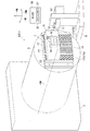
本発明の実施形態に係る位置決め装置1は、たとえば、工作機械3(たとえば旋盤等)に設置されて使用されるものであり、被加工物W(ワーク;たとえばレンズアレイの金型)が一体的に設置された状態で、旋盤3の面板5(回転主軸)に一体的に設置されるようになっている。
The positioning device 1 according to the embodiment of the present invention is used by being installed on, for example, a machine tool 3 (for example, a lathe), and a workpiece W (workpiece; for example, a lens array mold) is integrated. In a state where the
ここで、説明の便宜のために、水平方向の所定の一方向をX軸方向とし、鉛直方向(X軸方向に対して直交する上下方向)をY軸方向とし、水平方向の他の所定の一方向であってX軸方向とY軸方向とに対して直交する方向をZ軸方向とする。 Here, for convenience of explanation, a predetermined one direction in the horizontal direction is set as the X-axis direction, a vertical direction (vertical direction perpendicular to the X-axis direction) is set as the Y-axis direction, and another predetermined direction in the horizontal direction is set. A direction that is one direction and is orthogonal to the X-axis direction and the Y-axis direction is defined as a Z-axis direction.
旋盤3は、図1や図2で示すようにベッド(図示せず)と面板5と第1の移動体7と第2の移動体9と第3の移動体11とを備えて構成されている。
As shown in FIGS. 1 and 2, the
第1の移動体7は、上記ベッドに対してZ軸方向で、移動位置決め自在になっている。たとえば、第1の移動体7はリニアガイドベアリングを介して上記ベッドに支持されており、サーボモータ等のアクチュエータとボールねじ等を用いた機構とによって、上記ベッドに対して移動位置決め自在になっている。 The first moving body 7 is movable and positionable in the Z-axis direction with respect to the bed. For example, the first moving body 7 is supported on the bed via a linear guide bearing, and can be moved and positioned with respect to the bed by an actuator such as a servo motor and a mechanism using a ball screw or the like. Yes.
第2の移動体9は、上記ベッドに対してX軸方向で、移動位置決め自在になっている。たとえば、第2の移動体9はリニアガイドベアリングを介して上記ベッドに支持されており、サーボモータ等のアクチュエータとボールねじ等を用いた機構とによって、上記ベッドに対して移動位置決め自在になっている。
The second moving
第3の移動体11は、第2の移動体9に対してY軸方向で、移動位置決め自在になっている。たとえば、第3の移動体11はリニアガイドベアリングを介して第2の移動体9に支持されており、サーボモータ等のアクチュエータとボールねじ等を用いた機構とによって、第2の移動体9に対して移動位置決め自在になっている。
The third moving
なお、第3の移動体11が、X軸方向、Y軸方向およびZ軸方向で、第1の移動体7に対して相対的に移動位置決め自在になっているのであれば、必ずしも上述した構成になっている必要は無い。
Note that the above-described configuration is not necessarily required if the third moving
面板5は、たとえば、円板状に形成されており、この中心軸(C軸)がZ軸と平行になって、第1の移動体7にベアリングを介して支持されており、図示しないサーボモータ等のアクチュエータのよってC軸を回転中心にして第1の移動体7に対し回転し、所定の回転角度で停止できるようになっている。
The
また、面板5の円形状の面(位置決め装置1が一体的に設置される第3の移動体11側の面)は、第3の移動体11に対向している。第3の移動体11には、切削工具(バイト)10が一体的に設置されるようになっている。
Further, the circular surface of the face plate 5 (the surface on the side of the third moving
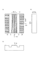
位置決め装置1は、図3等で示すように、第1の位置決め部材13と第2の位置決め部材15とを備えて構成されている。第1の位置決め部材13には、図4等で示すように、複数の「V」字状の凹凸17,19がならんで設けられている(溝21と突起23とが交互にならんで設けられている)。
As shown in FIG. 3 and the like, the positioning device 1 includes a
第2の位置決め部材15は、第1の位置決め部材13とは別体で構成されている。また、第2の位置決め部材15には、図5等で示すように、複数の第2の「V」字状の凹凸25,27がならんで設けられている(溝21と突起23とが交互にならんで設けられている)。
The
そして、第1の位置決め部材13の複数の「V」字状の凹凸17,19と、第2の位置決め部材15の複数の「V」字状の凹凸25,27とがお互いに噛み合うことで、第1の位置決め部材13に対する第2の位置決め部材15の位置決め(第1の位置での位置決め)がされるようになっている。すなわち、第1の位置決め部材13の複数の「V」字状の凹凸17,19がならんでいる方向および第2の位置決め部材15の複数の「V」字状の凹凸25,27がならんでいる方向で、第1の位置決め部材13に対する前記第2の位置決め部材15の位置決めがされるように構成されている。
The plurality of “V” -shaped
さらに、第1の位置決め部材13の複数の「V」字状の凹凸17,19に対する第2の位置決め部材15の複数の「V」字状の凹凸25,27の噛み合わせ位置をずらす(噛み合わせ位置を変える)ことで、第1の位置決め部材13に対する第2の位置決め部材15の異なる位置での位置決め(上記第1の位置とは異なる第2の位置での位置決め)がされるように構成されている(図1で示す第2の位置決め部材15の位置と図2で示す第2の位置決め部材15の位置とを参照)。
Further, the meshing positions of the plurality of “V” -shaped
第1の位置決め部材13の複数の「V」字状の凹凸は、図4(b)で示すように、所定の一方向(たとえば縦方向)にならんでいる第1の複数の「V」字状の凹凸17と、上記所定の一方向に対して交差する方向(たとえば直交する方向;横方向)にならんでいる第2の複数の「V」字状の凹凸19とを備えて構成されている。
As shown in FIG. 4B, the plurality of “V” -shaped irregularities of the
第2の位置決め部材15の複数の「V」字状の凹凸は、図5(a)で示すように、所定の一方向(たとえば縦方向)にならんでいる第3の複数の「V」字状の凹凸25と、上記所定の一方向に対して交差する方向(たとえば、横方向)にならんでいる第4の複数の「V」字状の凹凸27とを備えて構成されている。
As shown in FIG. 5A, the plurality of “V” -shaped irregularities of the
そして、図1〜図3で示すように、第1の複数の「V」字状の凹凸17と第3の複数の「V」字状の凹凸25とがお互いに噛み合い、第2の複数の「V」字状の凹凸19と第4の複数の「V」字状の凹凸27とがお互いに噛み合うことで、第1の位置決め部材13に対する第2の位置決め部材15の位置決め(縦方向および横方向での二次元方向での位置決め)がされるように構成されている。
As shown in FIGS. 1 to 3, the first plurality of “V” -shaped
さらに、上述した噛み合いにより、縦方向および横方向に直交する厚さ方向でも、第1の位置決め部材13に対する第2の位置決め部材15の位置決めがされるようになっている。この厚さ方向での位置決め位置は、縦方向および横方向で、第1の位置決め部材13に対する第2の位置決め部材15の位置をずらした場合でも、一定になっている。
Further, by the above-described engagement, the
第1の位置決め部材13は、図4で示すように、たとえば矩形な平板状(円板状等の矩形以外の平板状であってもよい。)に形成されており、図4(a)で示すように、厚さ方向の一方の面(一方の側)の一部に第1の複数の「V」字状の凹凸17が形成されており、厚さ方向の一方の面(他方の側)の他の一部に第2の複数の「V」字状の凹凸19が形成されている。
As shown in FIG. 4, the
第1の位置決め部材13の厚さ方向の一方の面の残りの部位には、凹部29が設けられている。この凹部29は、第1の位置決め部材13の複数の「V」字状の凹凸17,19と第2の位置決め部材15の複数の「V」字状の凹凸25,27との干渉を避けるためのものである。
A
すなわち、凹部29は、第1の位置決め部材13の複数の「V」字状の凹凸17,19と第2の位置決め部材15の複数の「V」字状の凹凸25,27とがお互いに噛み合うことで、第1の位置決め部材13に対する第2の位置決め部材15の位置決めがされ、また、第1の位置決め部材13の複数の「V」字状の凹凸17,19に対する第2の位置決め部材15の複数の「V」字状の凹凸25,27の噛み合わせ位置をずらすことで、第1の位置決め部材13に対する第2の位置決め部材15の異なる位置での位置決めがされたときに、第1の位置決め部材13の複数の「V」字状の凹凸17,19と第2の位置決め部材15の複数の「V」字状の凹凸25,27との干渉を避けるために設けられている。
That is, in the
第1の位置決め部材13の厚さ方向の他方の面は平面状になっている。
The other surface in the thickness direction of the
第2の位置決め部材15も、図5で示すように、第1の位置決め部材13と同様にして、たとえば矩形な平板状(円板状等の矩形以外の平板状であってもよい。)に形成されており、図5(a)で示すように、厚さ方向の一方の面の一部に第3の複数の「V」字状の凹凸25が形成されており、厚さ方向の一方の面の他の一部に第4の複数の「V」字状の凹凸27が形成されている。
As shown in FIG. 5, the
第2の位置決め部材15の厚さ方向の一方の面の残りの部位には、第1の位置決め部材13と同様に、凹部31が設けられている。この凹部31は、第1の位置決め部材13の複数の「V」字状の凹凸17,19と第2の位置決め部材15の複数の「V」字状の凹凸25,27との干渉を避けるために設けられている。
Similar to the
第2の位置決め部材15の厚さ方向の他方の面は平面状になっている。
The other surface in the thickness direction of the
位置決め装置1についてさらに詳しく説明する。 The positioning device 1 will be described in more detail.
第1の位置決め部材13では、前述したように、第1の複数の「V」字状の凹凸17と第2の複数の「V」字状の凹凸19とが、第1の位置決め部材13の厚さ方向の一方の側に設けられている。第1の複数の「V」字状の凹凸17は、縦方向にならんで、横方向の両端部に設けられている。
In the
第1の複数の「V」字状の凹凸17は、図4(c)、(d)で示すように、横方向に直交する平面による断面形状が、「V」字状の一形態である台形(たとえば等脚台形)の波形状に形成されている。なお、台形の波形状に代えて三角(たとえば二等辺三角形もしくは正三角形)の波形状に形成されていてもよい。
As shown in FIGS. 4C and 4D, the first plurality of “V” -shaped
さらに説明すると、図4(d)で示すように、第1の複数の「V」字状の凹凸17の上記断面形状は、お互いが同形状の複数の等脚台形33を所定のピッチP1で所定の方向にならべた波形状に形成されている。
More specifically, as shown in FIG. 4 (d), the cross-sectional shape of the first plurality of “V” -shaped projections and
上記所定の方向は、第1の複数の「V」字状の凹凸17がならんでいる方向(縦方向)であり、等脚台形33の下底や上底の延伸方向である。所定のピッチP1は、お互いに隣接している等脚台形33における一方の等脚台形33Aの中心点と、上記お互いに隣接している等脚台形33における他方の等脚台形33Bの中心点との間の距離であり、所定のピッチP1の値は、等脚台形33の下底の長さL1の値よりも大きく、等脚台形33の下底の長さL1と等脚台形33の上底L2の長さとの和の値よりも小さくなっている。
The predetermined direction is a direction (vertical direction) along which the first plurality of “V” -shaped projections and
上記断面形状において、各等脚台形33の上底と、一対の斜辺と、お互いに隣接している等脚台形33(33A,33B)をつないでいる直線(接続直線)35とで構成されている波形状の線が、第1の位置決め部材13の複数の凹凸17における、第1の位置決め部材13の肉部と、第1の位置決め部材13の外側に空間との境界線になっている。
In the cross-sectional shape, it is constituted by the upper base of each
なお、互いに隣接している等脚台形33をつないでいる接続直線35は、図4(d)で示すように、等脚台形33の下底の延長線状にあり、お互いに隣接している等脚台形33における一方の等脚台形33Aの角(お互いに隣接している等脚台形における他方の等脚台形33Bに最も近い角)37と、お互いに隣接している等脚台形33における他方の等脚台形33Bの角(お互いに隣接している等脚台形における一方の等脚台形33Aに最も近い角)39とつないでいる。
In addition, the connection
また、第1の位置決め部材13の肉部と、第1の位置決め部材13の外側に空間との境界線では、等脚台形33を含む側の部位が、第1の位置決め部材13の肉部になっている。また、各等脚台形33の部位が、第1の複数の「V」字状の凹凸17の凸部を形成しており、各等脚台形33の間の部位が、第1の複数の「V」字状の凹凸17の凹部を形成している。
In addition, at the boundary between the meat part of the
これから理解されるように、第1の複数の「V」字状の凹凸17は、ライン・アンド・スペースの形態で第1の位置決め部材13に設けられている。
As will be understood, the first plurality of “V” -shaped projections and
また、第1の複数の「V」字状の凹凸17は、図4(b)で示すように、縦方向では、第1の位置決め部材13の全長にわたって設けられており、横方向では、第1の位置決め部材13の両端部に設けられている。ここで、両端部のうちの一方の端部は、第1の位置決め部材13の横方向の一端41と、この一端41から他端側に所定の距離だけ離れた箇所43との間の部位であり、両端部のうちの他方の端部は、第1の位置決め部材13の横方向の他端45からとこの他端から一端側に所定の距離だけ離れた箇所47との間の部位である。
Further, as shown in FIG. 4B, the first plurality of “V” -shaped
第2の複数の「V」字状の凹凸19は、図4(b)で示すように、横方向にならんで横方向の中央部に設けられている。
As shown in FIG. 4B, the second plurality of “V” -shaped projections and
また、第2の複数の「V」字状の凹凸19は、第1の複数の「V」字状の凹凸17と同様にして、縦方向に直交する平面による断面形状が、台形(たとえば等脚台形)の波形状もしくは三角(たとえば二等辺三角形もしくは正三角形)の波形状に形成されている。
Similarly to the first plurality of “V” -shaped
さらに説明すると、第2の複数の「V」字状の凹凸19は、縦方向では、第1の位置決め部材13の全長にわたって設けられており、横方向では、第1の位置決め部材13の中央部に設けられている。
More specifically, the second plurality of “V” -shaped
なお、第2の複数の「V」字状の凹凸19の形状は、第1の複数の「V」字状の凹凸17の形状と等しくなっているが、第2の複数の「V」字状の凹凸19の形状が、第1の複数の「V」字状の凹凸17の形状と異なっていてもよい。たとえば、ピッチP1が異なっていてもよい。
The shape of the second plurality of “V” -shaped
第1の位置決め部材13の凹部29は、縦方向では、第1の位置決め部材13の全長にわたって設けられており、横方向では、第2の複数の「V」字状の凹凸19と一方の第1の複数の「V」字状の凹凸17Aとの間、および、第2の複数の「V」字状の凹凸19と他方の第1の複数の「V」字状の凹凸17Bとの間に設けられている。
The
第1の複数の「V」字状の凹凸17の等脚台形33と第2の複数の「V」字状の凹凸19の等脚台形とは、第1の位置決め部材13の厚さ方向で同じところに位置しており、また、第1の位置決め部材13の凹部29での第1の位置決め部材13の厚さは、第1の複数の「V」字状の凹凸17の等脚台形33(第2の複数の「V」字状の凹凸19の等脚台形)の下底のところにおける第1の位置決め部材13の厚さよりも、薄くなっている。
The
第2の位置決め部材15でも、前述したように、第3の複数の「V」字状の凹凸25と第4の複数の「V」字状の凹凸27とは、図5で示すように、第2の位置決め部材15の厚さ方向の一方の側に設けられている。
Also in the
第3の複数の「V」字状の凹凸25は、縦方向にならんで、横方向の両端部に設けられており、第1の複数の「V」字状の凹凸17と同様にして、横方向に直交する平面による断面形状が、台形(たとえば等脚台形)の波形状もしくは三角(たとえば二等辺三角形もしくは正三角形)の波形状に形成されている。
The third plurality of “V” -shaped
さらに説明すると、第3の複数の「V」字状の凹凸25は、縦方向では、第2の位置決め部材15の全長にわたって設けられており、横方向では、第2の位置決め部材15の両端部に設けられている。
More specifically, the third plurality of “V” -shaped
第4の複数の「V」字状の凹凸27は、横方向にならんで横方向の中央部に設けられており、第1の複数の「V」字状の凹凸17や第2の複数の「V」字状の凹凸19と同様にして、縦方向に直交する平面による断面形状が、台形(たとえば等脚台形)の波形状もしくは三角(たとえば二等辺三角形もしくは正三角形)の波形状に形成されている。
The fourth plurality of “V” -shaped projections and
さらに説明すると、第1の位置決め部材13と同様にして、第4の複数の「V」字状の凹凸27は、縦方向では、第2の位置決め部材15の全長にわたって設けられており、横方向では、第2の位置決め部材15の中央部に設けられている。
More specifically, as in the
第2の位置決め部材15の凹部(干渉を避けるための凹部)31は、第2の位置決め部材15の全長にわたって設けられており、横方向では、第4の複数の「V」字状の凹凸27と一方の第3の複数の「V」字状の凹凸25との間、および、第4の複数の「V」字状の凹凸27と他方の第3の複数の「V」字状の凹凸25との間に設けられている。
A concave portion (a concave portion for avoiding interference) 31 of the
第3の複数の「V」字状の凹凸25の等脚台形と第4の複数の「V」字状の凹凸27の等脚台形とは、第2の位置決め部材15の厚さ方向で同じところに位置しており、また、第2の位置決め部材15の凹部31での第2の位置決め部材15の厚さは、第3の複数の「V」字状の凹凸25の等脚台形(第4の複数の「V」字状の凹凸の等脚台形)の下底のところにおける第2の位置決め部材15の厚さよりも、薄くなっている。
The isosceles trapezoid of the third plurality of “V” shaped
なお、第1の位置決め部材13の凹部29と第2の位置決め部材15の凹部31とは、第2の位置決め部材15を横方向に移動して第1の位置決め部材13に対して位置決めしたときに、第1の複数の「V」字状の凹凸17と第4の複数の「V」字状の凹凸27とのお互いの干渉を避けるとともに第2の複数の「V」字状の凹凸19と第3の複数の「V」字状の凹凸25とのお互いの干渉を避けるために設けられている。
The
次に、第2の位置決め部材15を第1の位置決め部材13に対し横方向に移動して、第1の位置決め部材13に対して位置決めしたときの態様を、図3を参照して説明する。
Next, an aspect when the
図3(a)、(b)で示す態様では、第1の位置決め部材13の第1の複数の「V」字状の凹凸17の総てと第2の位置決め部材15の第3の複数の「V」字状の凹凸25の総てとがお互いに噛み合い、第1の位置決め部材13の第2の複数の「V」字状の凹凸19の総てと第2の位置決め部材15の第4の複数の「V」字状の凹凸27の総てとがお互いに噛み合うことで、縦方向、横方向および厚さ方向で、第1の位置決め部材13に対する第2の位置決め部材15の位置決めがされている。
3A and 3B, all of the first plurality of “V” -shaped
この状態から、第1の位置決め部材13に対し第2の位置決め部材15をこの厚さ方向であって第1の位置決め部材13から離れる方向に移動して、第2の位置決め部材15を第1の位置決め部材13から離し、第2の位置決め部材15を第1の位置決め部材13に対して1ピッチP1だけ横方向に移動し、第1の位置決め部材13に対し第2の位置決め部材15をこの厚さ方向であって第1の位置決め部材13に近づく方向に移動して、第1の位置決め部材13の第1の複数の「V」字状の凹凸17と第2の位置決め部材15の第3の複数の「V」字状の凹凸25とをお互いに噛み合わせ第1の位置決め部材13の第2の複数の「V」字状の凹凸19と第2の位置決め部材15の第4の複数の「V」字状の凹凸27をお互いに噛み合せることで、図3(c)で示すように、第2の位置決め部材15が第1の位置決め部材13に対し左方向に1ピッチP1だけずれた状態になる。
From this state, the
ところで、縦方向、横方向および厚さ方向で、第1の位置決め部材13に対する第2の位置決め部材15の位置決めがされるのであれば、各凹凸17,19,25,27の配置を適宜変更してもよい。たとえば、第1の複数の「V」字状の凹凸17および第3の複数の「V」字状の凹凸25を横方向にならべ、第2の複数の「V」字状の凹凸19および第4の複数の「V」字状の凹凸27を縦方向にならべてもよい。
By the way, if the
また、旋盤3の面板5には、第1の位置決め部材13を位置決めするための第1の位置決め部材位置決め部(図示せず)が設けられている。上記第1の位置決め部材位置決め部は、たとえば、第1の位置決め部材13の縦方向の端面および横方向の端面が突き当たる突き当てで構成されている。
The
また、第1の位置決め部材13は、たとえば、この横方向の両端41,45から突出している突出部49に設けられている貫通孔50と、ボルト(図示せず)とを用い、また、厚さ方向の他方の平面が面板5に当接し、上記第1の位置決め部材位置決め部に縦方向の端面および横方向の端面が突き当たることで、面板5の所定の位置で面板5に一体的に設置されるようになっている。上記所定の位置では、第1の位置決め部材13中心が、C軸上に存在している。
Moreover, the
また、第2の位置決め部材15は、固定部(図示せず)によって、各凹凸17,19,25,27が噛み合ったときに、第1の位置決め部材13(面板5でもよい)に一体的に設置される(固定される)ようになっている。上記固定部として、ボルト、磁石、真空吸着等を掲げることができる。
Further, the
たとえば、第1の位置決め部材13の複数の「V」字状の凹凸17,19(等脚台形33の斜面の中央部)に多数の貫通孔を設け、この多数の貫通孔を介して、第2の位置決め部材15(図3の状態になっている第2の位置決め部材15)を真空吸着するように構成されている。
For example, a plurality of through holes are provided in the plurality of “V” -shaped
被加工物(ワーク)Wは、図1や図2で示すように、たとえば直方体状に形成されており、厚さ方向の一方の面に、バイト(刃具;切削工具)10によって、たとえば、複数の球冠状の凹部W1,W2,W3,W4・・・が切削加工で形成されるようになっている。複数の球冠状の凹部W1,W2,W3,W4・・・のピッチは、たとえば、各凹凸17,19,25,27のピッチP1と一致しているが、ピッチP1の整数倍になっていてもよい。
The workpiece (workpiece) W is formed in a rectangular parallelepiped shape, for example, as shown in FIGS. 1 and 2, and a plurality of, for example, a plurality of workpieces (cutting tools; cutting tools) are formed on one surface in the thickness direction. The spherical crown-shaped recesses W1, W2, W3, W4... Are formed by cutting. The pitch of the plurality of spherical crown-shaped recesses W1, W2, W3, W4,... Coincides with the pitch P1 of the
第2の位置決め部材15には、ワークWを第2の位置決め部材15に対して所定の位置に位置決めするためのワーク位置決め部(図示せず)が設けられている。上記ワーク位置決め部は、たとえば、ワークWの縦方向の端面および横方向の端面が突き当たる突き当てで構成されている。また、第2の位置決め部材15とワークWとをこれらの厚さ方向から見ると、上記所定の位置では、たとえば、第2の位置決め部材15の中心とワークWの中心とがお互いに一致している。
The
ワークWは、固定部(図示せず)をよって、第2の位置決め部材15に一体的に設置されるようになっている。上記固定部として、ボルト、磁石、真空吸着等を掲げることができる。
The workpiece W is integrally installed on the
なお、すでに理解されるように、第1の位置決め部材13は、面板5に対して着脱自在になっている。ワークWは、第2の位置決め部材15に対して着脱自在になっている。
As already understood, the
次に、位置決め装置1と、旋盤3とを備えて構成されている位置決めシステム51について、図1、図2等を参照しつつ説明する。
Next, a
位置決めシステム51は、位置決め装置1の他に、位置決め部材設置体(たとえば旋盤3の面板5)と、第2の位置決め部材保持体53と、上述した固定部(第1の位置決め部材13と第2の位置決め部材15をお互いに固定する固定部;各位置決め部材固定部)と、CPU55とメモリ57とを備えて構成された制御部59とを備えて構成されている。
In addition to the positioning device 1, the
位置決め部材設置体(面板)5には、第1の位置決め部材13が一体的に設置されようになっている。
A
第2の位置決め部材保持体53は、たとえば、Y軸方向で第2の移動体9に対して移動位置決め自在になっている。これにより、第2の位置決め部材保持体53は、面板5に対してX軸方向、Y軸方向およびZ軸方向で移動位置決め自在になっている。
For example, the second positioning
Z軸方向は、位置決め部材設置体5に設置されている第1の位置決め部材13に第2の位置決め部材15を近づけて、第1の位置決め部材13に対する第2の位置決め部材15の位置決めをするときの第2の位置決め部材15の移動方向であり、また、位置決め部材設置体5に設置されている第1の位置決め部材13から第2の位置決め部材15を離すときの第2の位置決め部材15の移動方向である。
The Z-axis direction is when the
X軸方向やY軸方向は、第2の位置決め部材15の上記移動方向(Z軸方向)に対して交差する方向(たとえば直交する方向)である。
The X-axis direction and the Y-axis direction are directions (for example, orthogonal directions) that intersect the moving direction (Z-axis direction) of the
また、第2の位置決め部材保持体53は、第2の位置決め部材15を着脱自在になっている(保持し、また、解放することができるようになっている)。
Further, the second positioning
上述した図示していない固定部(第1の位置決め部材13に第2の位置決め部材15を固定する固定部;各位置決め部材固定部)は、第1の位置決め部材13に第2の位置決め部材15の位置決めがされているときに第1の位置決め部材13に第2の位置決め部材15を固定するようになっている(固定しまたこの固定を解除自在になっている)。
The above-described fixing portions (not shown) (fixing portions for fixing the
制御部59は、予めメモリ57に記憶されている動作プログラムに基づき、次に示すようにして、位置決め部材保持体53と上記各位置決め部材固定部とを制御するよういなっている。
The
すなわち、まず、面板5に所定の位置に固定されている第1の位置決め部材13に第2の位置決め部材15の位置決めがされている状態で、位置決め部材保持体53を第2の位置決め部材15に係合させて、位置決め部材保持体53で第2の位置決め部材15を保持するようになっている。
That is, first, in a state where the
続いて、上記保持後に、上記各位置決め部材固定部での第1の位置決め部材13と第2の位置決め部材15との固定を解除し、位置決め部材保持体53を第2の位置決め部材15とともに第1の位置決め部材13から離す方向に移動(第1の位置決め部材13の複数の「V」字状の凹凸17,19から第2の位置決め部材15の複数の「V」字状の凹凸25,27が完全に抜けるまで移動)するようになっている。
Subsequently, after the holding, the fixing of the
続いて、上記移動後に、第2の位置決め部材15を保持している位置決め部材保持体53を、第2の位置決め部材15の移動方向(Z軸方向)に対して交差する方向(X軸方向やY軸方向)に所定の距離だけ移動して位置決めするようになっている。
Subsequently, after the movement, the positioning
この移動位置決め後に、位置決め部材設置体(面板)5に設置されている第1の位置決め部材13の複数の「V」字状の凹凸17,19と、位置決め部材保持体53に保持されている第2の位置決め部材15の複数の「V」字状の凹凸25,27とがお互いに噛み合うまで、第2の位置決め部材15を保持している位置決め部材保持体53を、位置決め部材設置体5に設置されている第1の位置決め部材13に近づけて、第1の位置決め部材13に対する第2の位置決め部材15の位置決めをするようになっている。
After this movement positioning, the plurality of “V” -shaped
続いて、上記位置決め後に、上記各位置決め部材固定部で第1の位置決め部材13と第2の位置決め部材15をお互いに固定するようになっている。
Subsequently, after the positioning, the
続いて、位置決め部材保持体53が第2の位置決め部材15の保持を解除して第2の位置決め部材15から離れるようになっている。
Subsequently, the positioning
次に、位置決めシステム51の動作について説明する。
Next, the operation of the
初期状態として、第3の移動体11に切削工具10が設置されており、面板(位置決め部材設置体)5に第1の位置決め部材13が設置されており、第2の位置決め部材15が第1の位置決め部材13に設置されており、第2の位置決め部材15にワークWが設置されているものとする。
As an initial state, the cutting
上記初期状態で、制御部59の制御の下、面板5をたとえば一方向に回転し、これによってワークWがC軸を中心にして回転しているときに、バイト10(第3の移動体11)を面板5に対して適宜移動し、1つ目の凹部W1を加工する(図6(a)参照)。なお、すでに理解されるように、1つ目の凹部W1の中心は、C軸上に存在している。なお、図6では、位置決め装置1の表示を省略している。
In the initial state, under the control of the
この加工が終えた後、面板5の回転を停止する。この停止状態では、たとえば、第1の位置決め部材13や第2の位置決め部材15の縦方向がY軸方向になっており、第1の位置決め部材13や第2の位置決め部材15の横方向がX軸方向になっている。
After this processing is completed, the rotation of the
続いて、面板5の回転の停止後、第2の位置決め部材保持体53等を用い、上述したようにして、第1の位置決め部材13に対する第2の位置決め部材15の位置をX軸方向やY軸方向で適宜ずらして、第1の位置決め部材13に対する第2の位置決め部材15の再度の位置決めをする。
Subsequently, after the rotation of the
この再度の位置決め後に、面板5をたとえば一方向に回転し、これによってワークWがC軸を中心にして回転しているときに、バイト10(第3の移動体11)を面板5に対して適宜移動し、2つ目の凹部W2を加工する(図6(b)参照)。2つ目の凹部W2の中心は、すでに理解されるように、C軸上に存在している。以下、同様にして、3つ目以降の凹部W3・・を加工する。
After the positioning again, the
なお、上記説明では、第2の位置決め部材保持体53を用いて、第2の位置決め部材15の移動位置決めをしているが、手動によって第2の位置決め部材15の移動位置決めをしてもよい。
In the above description, the
位置決め装置1によれば、第1の位置決め部材13の複数の「V」字状の凹凸17,19に対する第2の位置決め部材15の複数の「V」字状の凹凸25,27の噛み合わせ位置をずらすことで、第1の位置決め部材13に対する第2の位置決め部材15の異なる位置での位置決めがされるように構成されているので、第1の位置決め部材13に対する第2の位置決め部材15の位置合わせに要する時間を短縮することができ、第1の位置決め部材13に対する第2の位置決め部材15の位置合わせ精度を向上させることができ、しかも、第1の位置決め部材13に対して第2の位置決め部材15を、位置ずれが発生しないように強固に固定することができる。
According to the positioning device 1, the engagement positions of the plurality of “V” -shaped
また、第2の位置決め部材15に被加工物Wが固定されていることで、被加工物Wの位置合わせに要する時間を短縮することができ、被加工物Wの位置合わせ精度が向上し、被加工物Wの位置合わせの作業性が向上する。
In addition, since the workpiece W is fixed to the
また、位置決め装置1によれば、第1の複数の「V」字状の凹凸17と第3の複数の「V」字状の凹凸25とが噛み合い、第2の複数の「V」字状の凹凸19と第4の複数の「V」字状の凹凸27とが噛み合うことで、X軸方向およびY軸方向での二次元方向で、第1の位置決め部材13に対する第2の位置決め部材15の位置決めがなされるように構成されているので、被加工物Wの複数個所(X軸方向およびY軸方向での二次元方向にたとえば所定のピッチでならんでいる加工箇所)の位置関係を、1mm以下の細かいピッチP1に設置しても、正確なものとすることができる。
Further, according to the positioning device 1, the first plurality of “V” -shaped
また、位置決め装置1によれば、位置決め部材保持体53によって第2の位置決め部材15の移動がなされるので、各位置決め部材13,15の凹凸17,19,25,27ピッチP1が、肉眼では見にくい大きさ(たとえば1mmに満たない小さい値)であっても、第1の位置決め部材13に対する第2の位置決め部材15の位置の変更を容易に行うことができる。
Further, according to the positioning device 1, since the
なお、各位置決め部材13,15の凹凸を削除し、各位置決め部材13,15の平面同士をお互いに面接触させて、第1の位置決め部材13に対する第2の位置決め部材15の位置決めをするようにしてもよい。
Note that the unevenness of each positioning
すなわち、次のように位置決めシステム構成してもよい。 That is, the positioning system may be configured as follows.
第1の位置決め部材と、第2の位置決め部材とを備え、前記第1の位置決め部材に対する前記第2の位置決め部材の位置決めがされるとともに、前記第1の位置決め部材に対する前記第2の位置決め部材の位置をずらすことで、前記第1の位置決め部材に対する前記第2の位置決め部材の異なる位置での位置決めがされるように構成されている位置決め装置と、前記第1の位置決め部材が設置される位置決め部材設置体と、前記位置決め部材設置体に設置されている第1の位置決め部材に前記第2の位置決め部材を近づけて、前記第1の位置決め部材に対する前記第2の位置決め部材の位置決めをするときの、前記第2の位置決め部材の移動方向と、前記第2の位置決め部材の移動方向に対して交差する方向とで、前記位置決め部材設置体対して移動位置決め自在であるとともに、前記第2の位置決め部材を着脱自在な位置決め部材保持体と、前記第1の位置決め部材に前記第2の位置決め部材の位置決めがされているときに前記第1の位置決め部材に前記第2の位置決め部材を固定する固定部と、前記第1の位置決め部材に前記第2の位置決め部材の位置決めがされている状態で、前記位置決め部材保持体で前記第2の位置決め部材を保持し、この保持後に、前記固定部での前記第1の位置決め部材と前記第2の位置決め部材との固定を解除し、前記位置決め部材保持体を前記第1の位置決め部材から離す方向に移動し、この移動後に、前記第2の位置決め部材を保持している前記位置決め部材保持体を、前記第2の位置決め部材の移動方向に対して交差する方向に移動位置決めし、この移動位置決め後に、前記第2の位置決め部材を保持している前記位置決め部材保持体を、前記位置決め部材設置体に設置されている第1の位置決め部材に近づけて、前記第1の位置決め部材に前記第2の位置決め部材が係合させ、前記第1の位置決め部材に対する前記第2の位置決め部材の位置決めをし、この位置決め後に、前記固定部で前記第1の位置決め部材と前記第2の位置決め部材を固定するように、前記位置決め部材保持体と前記固定部とを制御する制御部とを有する位置決めシステムとしてもよい。 A first positioning member; a second positioning member; wherein the second positioning member is positioned with respect to the first positioning member; and the second positioning member is positioned with respect to the first positioning member. A positioning device configured to position the second positioning member at different positions with respect to the first positioning member by shifting the position, and a positioning member on which the first positioning member is installed When positioning the second positioning member with respect to the first positioning member by bringing the second positioning member closer to the first positioning member installed on the installation body and the positioning member installation body, The positioning member installation body pair in a moving direction of the second positioning member and a direction intersecting the moving direction of the second positioning member. The first positioning member when the second positioning member is positioned on the first positioning member, and a positioning member holding body that is detachable and movable. A fixing portion that fixes the second positioning member to the member; and the second positioning member is held by the positioning member holding body in a state where the second positioning member is positioned by the first positioning member. After the holding, the fixing of the first positioning member and the second positioning member at the fixing portion is released, and the positioning member holding body is moved in a direction away from the first positioning member. After the movement, the positioning member holding body holding the second positioning member is moved and positioned in a direction crossing the moving direction of the second positioning member. After the movement positioning, the positioning member holding body holding the second positioning member is brought close to the first positioning member installed on the positioning member installation body, and the first positioning member is moved to the first positioning member. The second positioning member is engaged, the second positioning member is positioned with respect to the first positioning member, and after the positioning, the first positioning member and the second positioning member at the fixing portion. It is good also as a positioning system which has the control part which controls the said positioning member holding body and the said fixing | fixed part so that it may fix.
このように構成された位置決めシステムによれば、第1の位置決め部材と第2の位置決め部材とがそれぞれの平面がお互いに接触することで係合しているので、第1の位置決め部材に対する第2の位置決め部材の位置を、段階的でなく連続した範囲での中途の任意の位置で行うことができる。 According to the positioning system configured as described above, since the first positioning member and the second positioning member are engaged with each other by their respective planes contacting each other, the second positioning member with respect to the first positioning member is engaged. The position of the positioning member can be set at an arbitrary position midway within a continuous range, not in a stepwise manner.
また、上述したものを、被加工物の加工方法の発明として把握してもよい。 Moreover, you may grasp | ascertain what was mentioned above as invention of the processing method of a to-be-processed object.
すなわち、複数の「V」字状の凹凸がならんで設けられている第1の位置決め部材と、複数の第2の「V」字状の凹凸がならんで設けられている第2の位置決め部材とを有し、前記第1の位置決め部材の複数の「V」字状の凹凸と、前記第2の位置決め部材の複数の「V」字状の凹凸とがお互いに噛み合うことで、第1の位置決め部材の複数の「V」字状の凹凸がならんでいる方向および第2の位置決め部材の複数の「V」字状の凹凸がならんでいる方向で、前記第1の位置決め部材に対する前記第2の位置決め部材の位置決めがされるとともに、前記第1の位置決め部材の複数の「V」字状の凹凸に対する前記第2の位置決め部材の複数の「V」字状の凹凸の噛み合わせ位置をずらすことで、第1の位置決め部材の複数の「V」字状の凹凸がならんでいる方向および第2の位置決め部材の複数の「V」字状の凹凸がならんでいる方向で、前記第1の位置決め部材に対する前記第2の位置決め部材の異なる位置での位置決めがされるように構成されている位置決め装置を用いた被加工物の加工方法において、第1の位置決め部材が位置決め部材設置体に一体的に設置される設置されており、前記第2の位置決め部材の所定の位置に被加工物が一体的に設置されており、前記第1の位置決め部材に対して所定の位置で前記第2の位置決め部材の位置決めがされている状態(第1の位置決め部材と第2の位置決め部材とが一体化している状態)で、前記第1の位置決め部材を所定の軸(C軸)を回転中心にして回転しつつ、刃具を用いて、前記加工物の所定の箇所に加工を施す第1の加工工程と、前記第1の加工工程での加工後に、第2の位置決め部材の所定の位置に被加工物が一体的に設置されている状態を維持しつつ、前記第1の位置決め部材に対して前記所定の位置とは異なる所定の位置で前記第2の位置決め部材を再び位置決めし、この位置決めがされている状態(第1の位置決め部材と第2の位置決め部材とが一体化している状態)で、前記第1の位置決め部材を、第1の加工工程と同じ所定の軸(C軸)を回転中心にして回転しつつ、上記刃具を用いて、前記加工物の所定の箇所に加工を施す第2の加工工程とを有する被加工物の加工方法として把握してもよい。 That is, a first positioning member provided with a plurality of “V” -shaped irregularities, and a second positioning member provided with a plurality of second “V” -shaped irregularities, And the plurality of “V” -shaped irregularities of the first positioning member and the plurality of “V” -shaped irregularities of the second positioning member mesh with each other, so that the first positioning In the direction in which a plurality of “V” -shaped irregularities of the member are aligned and in the direction in which the plurality of “V” -shaped irregularities of the second positioning member are aligned, the second positioning relative to the first positioning member is performed. The positioning member is positioned, and the engagement positions of the plurality of “V” -shaped irregularities of the second positioning member with respect to the plurality of “V” -shaped irregularities of the first positioning member are shifted. , A plurality of "V" -shaped irregularities of the first positioning member The second positioning member is positioned at different positions with respect to the first positioning member in the direction in which the plurality of “V” -shaped irregularities of the second positioning member are aligned. In the processing method of the workpiece using the positioning device configured as described above, the first positioning member is installed integrally with the positioning member installation body, and a predetermined position of the second positioning member The workpiece is integrally installed in a state where the second positioning member is positioned at a predetermined position with respect to the first positioning member (the first positioning member and the second positioning member). The first positioning member is rotated about a predetermined axis (C-axis) as a center of rotation, and a predetermined portion of the workpiece is processed using a cutting tool. First addition And after the processing in the first processing step, with respect to the first positioning member while maintaining a state in which the workpiece is integrally installed at a predetermined position of the second positioning member In a state where the second positioning member is positioned again at a predetermined position different from the predetermined position and the positioning is performed (a state where the first positioning member and the second positioning member are integrated). The first positioning member is processed at a predetermined position of the workpiece by using the cutting tool while rotating the first positioning member about the same predetermined axis (C axis) as the first processing step. You may grasp | ascertain as a processing method of the to-be-processed object which has two processing processes.
なお、上記説明では、X軸方向およびZ軸方向を水平方向とし、Y軸方向を鉛直方向としているが、X軸方向、Y軸方向、Z軸方向とがお互いに直交しているのであれば、X軸方向もしくはZ軸方向を鉛直方向としてもよいし、X軸方向、Y軸方向、Z軸方向が斜めの方向になっていてもよい。 In the above description, the X-axis direction and the Z-axis direction are the horizontal direction, and the Y-axis direction is the vertical direction. However, as long as the X-axis direction, the Y-axis direction, and the Z-axis direction are orthogonal to each other. The X-axis direction or the Z-axis direction may be the vertical direction, and the X-axis direction, the Y-axis direction, and the Z-axis direction may be oblique directions.
1 位置決め装置
5 位置決め部材設置体(面板)
13 第1の位置決め部材
15 第2の位置決め部材
17 第1の複数の「V」字状の凹凸
19 第2の複数の「V」字状の凹凸
25 第3の複数の「V」字状の凹凸
27 第4の複数の「V」字状の凹凸
53 位置決め部材保持体
59 制御部
1
13
Claims (6)
複数の第2の「V」字状の凹凸がならんで設けられている第2の位置決め部材と、
を有し、前記第1の位置決め部材の複数の「V」字状の凹凸と、前記第2の位置決め部材の複数の「V」字状の凹凸とが噛み合うことで、前記第1の位置決め部材に対する前記第2の位置決め部材の位置決めがされるとともに、前記第1の位置決め部材の複数の「V」字状の凹凸に対する前記第2の位置決め部材の複数の「V」字状の凹凸の噛み合わせ位置をずらすことで、前記第1の位置決め部材に対する前記第2の位置決め部材の異なる位置での位置決めがされるように構成されていることを特徴とする位置決め装置。 A first positioning member provided with a plurality of "V" -shaped irregularities;
A second positioning member provided with a plurality of second “V” -shaped irregularities;
And the plurality of “V” -shaped irregularities of the first positioning member and the plurality of “V” -shaped irregularities of the second positioning member mesh with each other, so that the first positioning member The second positioning member is positioned with respect to the plurality of "V" -shaped irregularities of the first positioning member, and the plurality of "V" -shaped irregularities of the second positioning member are engaged with each other. A positioning apparatus configured to position the second positioning member with respect to the first positioning member at a different position by shifting the position.
前記第1の位置決め部材の複数の「V」字状の凹凸は、所定の一方向にならんでいる第1の複数の「V」字状の凹凸と、前記所定の一方向に対して交差する方向にならんでいる第2の複数の「V」字状の凹凸とを備えて構成されており、
前記第2の位置決め部材の複数の「V」字状の凹凸は、所定の一方向にならんでいる第3の複数の「V」字状の凹凸と、前記所定の一方向に対して交差する方向にならんでいる第4の複数の「V」字状の凹凸とを備えて構成されており、
前記第1の複数の「V」字状の凹凸と前記第3の複数の「V」字状の凹凸とが噛み合い、前記第2の複数の「V」字状の凹凸と前記第4の複数の「V」字状の凹凸とが噛み合うことで、前記第1の位置決め部材に対する前記第2の位置決め部材の位置決めがされるように構成されていることを特徴とする位置決め装置。 The positioning device according to claim 1,
The plurality of “V” -shaped irregularities of the first positioning member intersect the first plurality of “V” -shaped irregularities aligned in a predetermined direction with respect to the predetermined direction. A second plurality of "V" shaped irregularities aligned in a direction,
The plurality of “V” -shaped irregularities of the second positioning member intersect the third plurality of “V” -shaped irregularities aligned in a predetermined direction with respect to the predetermined direction. A fourth plurality of "V" -shaped irregularities aligned in a direction,
The first plurality of “V” -shaped irregularities mesh with the third plurality of “V” -shaped irregularities, and the second plurality of “V” -shaped irregularities and the fourth plurality The positioning device is configured such that the second positioning member is positioned with respect to the first positioning member by meshing with the "V" -shaped unevenness of the first positioning member.
前記第1の位置決め部材は、矩形な平板状に形成されており、
前記第1の複数の「V」字状の凹凸と前記第2の複数の「V」字状の凹凸とは、前記第1の位置決め部材の厚さ方向の一方の側に設けられており、
前記第1の複数の「V」字状の凹凸は、縦方向にならんで、横方向の両端部に設けられており、
前記第1の複数の「V」字状の凹凸は、横方向に直交する平面による断面形状が、台形の波形状もしくは三角の波形状に形成されており、
前記第2の複数の「V」字状の凹凸は、横方向にならんで横方向の中央部に設けられており、
前記第2の複数の「V」字状の凹凸は、縦方向に直交する平面による断面形状が、台形の波形状もしくは三角の波形状に形成されており、
前記第2の位置決め部材も、矩形な平板状に形成されており、
前記第3の複数の「V」字状の凹凸と前記第4の複数の「V」字状の凹凸とは、前記第2の位置決め部材の厚さ方向の一方の側に設けられており、
前記第3の複数の「V」字状の凹凸は、縦方向にならんで、横方向の両端部に設けられており、
前記第3の複数の「V」字状の凹凸は、横方向に直交する平面による断面形状が、台形の波形状もしくは三角の波形状に形成されており、
前記第4の複数の「V」字状の凹凸は、横方向にならんで横方向の中央部に設けられており、
前記第4の複数の「V」字状の凹凸は、縦方向に直交する平面による断面形状が、台形の波形状もしくは三角の波形状に形成されていることを特徴とする位置決め装置。 The positioning device according to claim 2, wherein
The first positioning member is formed in a rectangular flat plate shape,
The first plurality of “V” shaped irregularities and the second plurality of “V” shaped irregularities are provided on one side in the thickness direction of the first positioning member,
The first plurality of “V” -shaped irregularities are provided at both ends in the horizontal direction along the vertical direction,
The first plurality of “V” -shaped projections and depressions are formed in a trapezoidal wave shape or a triangular wave shape in a cross-sectional shape by a plane orthogonal to the lateral direction,
The second plurality of “V” -shaped irregularities are arranged in the lateral center along the lateral direction,
In the second plurality of “V” -shaped irregularities, the cross-sectional shape by a plane orthogonal to the vertical direction is formed into a trapezoidal wave shape or a triangular wave shape,
The second positioning member is also formed in a rectangular flat plate shape,
The third plurality of “V” -shaped irregularities and the fourth plurality of “V” -shaped irregularities are provided on one side in the thickness direction of the second positioning member,
The third plurality of “V” -shaped irregularities are provided at both ends in the horizontal direction along the vertical direction,
In the third plurality of “V” -shaped irregularities, the cross-sectional shape by a plane orthogonal to the lateral direction is formed into a trapezoidal wave shape or a triangular wave shape,
The fourth plurality of “V” -shaped irregularities are arranged in a laterally central portion along the lateral direction,
4. The positioning apparatus according to claim 4, wherein the fourth plurality of “V” -shaped projections and depressions are formed in a trapezoidal wave shape or a triangular wave shape in cross section by a plane orthogonal to the vertical direction.
前記第1の位置決め部材が設置される位置決め部材設置体と、
前記位置決め部材設置体に設置されている第1の位置決め部材に前記第2の位置決め部材を近づけて、前記第1の位置決め部材に対する前記第2の位置決め部材の位置決めをするときの、前記第2の位置決め部材の移動方向と、この移動方向に対して交差する方向とで、前記位置決め部材設置体に対して移動位置決め自在であるとともに、前記第2の位置決め部材を着脱自在な位置決め部材保持体と、
前記第1の位置決め部材に前記第2の位置決め部材の位置決めがされているときに前記第1の位置決め部材に前記第2の位置決め部材を固定する固定部と、
前記第1の位置決め部材に前記第2の位置決め部材の位置決めがされている状態で、前記位置決め部材保持体で前記第2の位置決め部材を保持し、この保持後に、前記固定部での前記第1の位置決め部材と前記第2の位置決め部材との固定を解除し、前記位置決め部材保持体を前記第1の位置決め部材から離す方向に移動し、この移動後に、前記第2の位置決め部材を保持している前記位置決め部材保持体を、前記第2の位置決め部材の移動方向に対して交差する方向に移動位置決めし、この移動位置決め後に、前記第1の位置決め部材の複数の「V」字状の凹凸と、前記第2の位置決め部材の複数の「V」字状の凹凸とが噛み合うまで、前記第2の位置決め部材を保持している前記位置決め部材保持体を、前記位置決め部材設置体に設置されている第1の位置決め部材に近づけて、前記第1の位置決め部材に対する前記第2の位置決め部材の位置決めをし、この位置決め後に、前記固定部で前記第1の位置決め部材と前記第2の位置決め部材を固定するように、前記位置決め部材保持体と前記固定部とを制御する制御部と、
を有することを特徴とする位置決めシステム。 The positioning device according to any one of claims 1 to 3,
A positioning member installation body on which the first positioning member is installed;
The second positioning member is positioned when the second positioning member is moved closer to the first positioning member installed in the positioning member installation body and the second positioning member is positioned with respect to the first positioning member. A positioning member holding body that is movable and positionable with respect to the positioning member installation body in a moving direction of the positioning member and a direction intersecting the moving direction, and the second positioning member is detachable;
A fixing portion that fixes the second positioning member to the first positioning member when the second positioning member is positioned on the first positioning member;
In a state where the second positioning member is positioned on the first positioning member, the second positioning member is held by the positioning member holding body, and after the holding, the first positioning member at the fixing portion The positioning member is released from the second positioning member, and the positioning member holding body is moved away from the first positioning member. After this movement, the second positioning member is held. The positioning member holding body is moved and positioned in a direction crossing the moving direction of the second positioning member, and after this movement positioning, a plurality of “V” -shaped irregularities of the first positioning member and The positioning member holding body holding the second positioning member is installed on the positioning member installation body until a plurality of “V” -shaped irregularities of the second positioning member are engaged with each other. The second positioning member is positioned relative to the first positioning member close to the first positioning member, and after the positioning, the first positioning member and the second positioning member at the fixing portion A control unit for controlling the positioning member holding body and the fixing unit so as to fix
A positioning system comprising:
前記第1の位置決め部材が設置される位置決め部材設置体と、
前記位置決め部材設置体に設置されている第1の位置決め部材に前記第2の位置決め部材を近づけて、前記第1の位置決め部材に対する前記第2の位置決め部材の位置決めをするときの、前記第2の位置決め部材の移動方向と、この移動方向に対して交差する方向とで、前記位置決め部材設置体に対して移動位置決め自在であるとともに、前記第2の位置決め部材を着脱自在な位置決め部材保持体と、
前記第1の位置決め部材に前記第2の位置決め部材の位置決めがされているときに前記第1の位置決め部材に前記第2の位置決め部材を固定する固定部と、
前記第1の位置決め部材に前記第2の位置決め部材の位置決めがされている状態で、前記位置決め部材保持体で前記第2の位置決め部材を保持し、この保持後に、前記固定部での前記第1の位置決め部材と前記第2の位置決め部材との固定を解除し、前記位置決め部材保持体を前記第1の位置決め部材から離す方向に移動し、この移動後に、前記第2の位置決め部材を保持している前記位置決め部材保持体を、前記第2の位置決め部材の移動方向に対して交差する方向に移動位置決めし、この移動位置決め後に、前記第2の位置決め部材を保持している前記位置決め部材保持体を、前記位置決め部材設置体に設置されている第1の位置決め部材に近づけて、前記第1の位置決め部材に前記第2の位置決め部材が係合させ、前記第1の位置決め部材に対する前記第2の位置決め部材の位置決めをし、この位置決め後に、前記固定部で前記第1の位置決め部材と前記第2の位置決め部材を固定するように、前記位置決め部材保持体と前記固定部とを制御する制御部と、
を有することを特徴とする位置決めシステム。 A first positioning member; a second positioning member; wherein the second positioning member is positioned with respect to the first positioning member; and the second positioning member is positioned with respect to the first positioning member. A positioning device configured to position the second positioning member at a different position with respect to the first positioning member by shifting the position;
A positioning member installation body on which the first positioning member is installed;
The second positioning member is positioned when the second positioning member is moved closer to the first positioning member installed in the positioning member installation body and the second positioning member is positioned with respect to the first positioning member. A positioning member holding body that is movable and positionable with respect to the positioning member installation body in a moving direction of the positioning member and a direction intersecting the moving direction, and the second positioning member is detachable;
A fixing portion that fixes the second positioning member to the first positioning member when the second positioning member is positioned on the first positioning member;
In a state where the second positioning member is positioned on the first positioning member, the second positioning member is held by the positioning member holding body, and after the holding, the first positioning member at the fixing portion The positioning member is released from the second positioning member, and the positioning member holding body is moved away from the first positioning member. After this movement, the second positioning member is held. The positioning member holding body is moved and positioned in a direction intersecting the moving direction of the second positioning member, and the positioning member holding body holding the second positioning member is moved after the movement positioning. The first positioning member is brought close to the first positioning member installed on the positioning member installation body, and the first positioning member is engaged with the second positioning member. Positioning the second positioning member with respect to the material, and fixing the first positioning member and the second positioning member with the fixing portion after the positioning, and the positioning member holding body and the fixing portion A control unit for controlling
A positioning system comprising:
前記第2の位置決め部材の所定の位置に被加工物が設置されており、前記第1の位置決め部材に対して所定の位置で前記第2の位置決め部材の位置決めがされている状態で、前記第1の位置決め部材を所定の軸を回転中心にして回転しつつ、前記加工物の所定の箇所に加工を施す第1の加工工程と、
前記第1の加工工程での加工後に、前記第1の位置決め部材に対して前記所定の位置とは異なる所定の位置で前記第2の位置決め部材を位置決めし、この位置決めがされている状態で、前記第1の位置決め部材を、第1の加工工程と同じ所定の軸を回転中心にして回転しつつ、前記加工物の所定の箇所に加工を施す第2の加工工程と、
を有することを特徴とする被加工物の加工方法。
A first positioning member provided with a plurality of "V" -shaped irregularities; and a second positioning member provided with a plurality of second "V" -shaped irregularities. The plurality of “V” -shaped irregularities of the first positioning member and the plurality of “V” -shaped irregularities of the second positioning member mesh with each other, so that the first positioning member The second positioning member is positioned, and the engagement positions of the plurality of “V” -shaped irregularities of the second positioning member with respect to the plurality of “V” -shaped irregularities of the first positioning member are determined. In a processing method of a workpiece using a positioning device configured to be positioned at a different position of the second positioning member with respect to the first positioning member by shifting,
The workpiece is installed at a predetermined position of the second positioning member, and the second positioning member is positioned at a predetermined position with respect to the first positioning member. A first processing step of processing a predetermined portion of the workpiece while rotating one positioning member about a predetermined axis as a rotation center;
After the processing in the first processing step, the second positioning member is positioned at a predetermined position different from the predetermined position with respect to the first positioning member. A second processing step of processing the predetermined position of the workpiece while rotating the first positioning member around the same predetermined axis as the first processing step;
A method for processing a workpiece, characterized by comprising:
Priority Applications (1)
| Application Number | Priority Date | Filing Date | Title |
|---|---|---|---|
| JP2016022528A JP2017140662A (en) | 2016-02-09 | 2016-02-09 | Positioning device, positioning system and working method of work-piece |
Applications Claiming Priority (1)
| Application Number | Priority Date | Filing Date | Title |
|---|---|---|---|
| JP2016022528A JP2017140662A (en) | 2016-02-09 | 2016-02-09 | Positioning device, positioning system and working method of work-piece |
Publications (1)
| Publication Number | Publication Date |
|---|---|
| JP2017140662A true JP2017140662A (en) | 2017-08-17 |
Family
ID=59627686
Family Applications (1)
| Application Number | Title | Priority Date | Filing Date |
|---|---|---|---|
| JP2016022528A Pending JP2017140662A (en) | 2016-02-09 | 2016-02-09 | Positioning device, positioning system and working method of work-piece |
Country Status (1)
| Country | Link |
|---|---|
| JP (1) | JP2017140662A (en) |
Cited By (1)
| Publication number | Priority date | Publication date | Assignee | Title |
|---|---|---|---|---|
| WO2021100476A1 (en) * | 2019-11-22 | 2021-05-27 | 株式会社東京精密 | Surface shape measuring device and surface shape measuring method |
-
2016
- 2016-02-09 JP JP2016022528A patent/JP2017140662A/en active Pending
Cited By (2)
| Publication number | Priority date | Publication date | Assignee | Title |
|---|---|---|---|---|
| WO2021100476A1 (en) * | 2019-11-22 | 2021-05-27 | 株式会社東京精密 | Surface shape measuring device and surface shape measuring method |
| US11525660B2 (en) | 2019-11-22 | 2022-12-13 | Tokyo Seimitsu Co., Ltd. | Surface shape measuring device and surface shape measuring method |
Similar Documents
| Publication | Publication Date | Title |
|---|---|---|
| JP5013134B2 (en) | Fastening material holder and fastening material positioning fastening device | |
| JP5355206B2 (en) | Processing apparatus and processing method | |
| JP2019509184A (en) | Universal chuck machine tool | |
| KR101462381B1 (en) | Tip machining appratus, tip and muluty pattern forming method using the tip | |
| JP2006297715A (en) | Method for producing annular optical element and method for producing mold for annular optical element | |
| JPH059204B2 (en) | ||
| JP2020108919A (en) | Work-piece holding device | |
| JP2017140662A (en) | Positioning device, positioning system and working method of work-piece | |
| JP2010017769A (en) | Method of machining sheet-like workpiece | |
| JP2011083867A (en) | Method and device for positioning workpiece | |
| JP5850527B2 (en) | Fitting, cutting device, and cutting method used for cutting | |
| JP2007090489A (en) | Die cutting method and device therefor | |
| JP7398112B2 (en) | Gripping device and positioning mechanism | |
| JP2008238285A (en) | Processing device and processing method | |
| JP2007268694A (en) | Chip forming method | |
| JP2008221747A (en) | Method for processing molding die for diffraction optical element | |
| JP2010188525A (en) | Machining method | |
| JP7033368B1 (en) | A method for manufacturing a mold for a retroreflective optical element and a method for manufacturing a retroreflective optical element. | |
| JP2015006713A (en) | Gear processing device | |
| JP6538355B2 (en) | Turning tool and true ball machining method | |
| JP7315973B2 (en) | roller support | |
| JPH0585287B2 (en) | ||
| JP2009274161A (en) | Machining device | |
| JP6590091B1 (en) | Machining center index device | |
| JP2006001003A (en) | Method for processing lens barrel with tubular wall for defining hole, and device for performing this method |