JP2017139727A - Mobile communication system and communication device - Google Patents
Mobile communication system and communication device Download PDFInfo
- Publication number
- JP2017139727A JP2017139727A JP2016178771A JP2016178771A JP2017139727A JP 2017139727 A JP2017139727 A JP 2017139727A JP 2016178771 A JP2016178771 A JP 2016178771A JP 2016178771 A JP2016178771 A JP 2016178771A JP 2017139727 A JP2017139727 A JP 2017139727A
- Authority
- JP
- Japan
- Prior art keywords
- antenna
- propagation path
- unit
- path characteristic
- characteristic information
- Prior art date
- Legal status (The legal status is an assumption and is not a legal conclusion. Google has not performed a legal analysis and makes no representation as to the accuracy of the status listed.)
- Granted
Links
- 238000004891 communication Methods 0.000 title claims abstract description 371
- 230000006854 communication Effects 0.000 title claims abstract description 371
- 238000010295 mobile communication Methods 0.000 title claims abstract description 127
- 230000005540 biological transmission Effects 0.000 claims description 98
- 230000008859 change Effects 0.000 claims description 29
- 238000009434 installation Methods 0.000 claims description 24
- 230000008054 signal transmission Effects 0.000 claims description 9
- 238000001514 detection method Methods 0.000 claims description 8
- 238000013500 data storage Methods 0.000 claims description 3
- 238000000034 method Methods 0.000 description 27
- 238000010586 diagram Methods 0.000 description 22
- 238000012986 modification Methods 0.000 description 20
- 230000004048 modification Effects 0.000 description 20
- 230000007274 generation of a signal involved in cell-cell signaling Effects 0.000 description 13
- 230000001133 acceleration Effects 0.000 description 8
- 230000010363 phase shift Effects 0.000 description 4
- 238000005516 engineering process Methods 0.000 description 3
- 238000012935 Averaging Methods 0.000 description 2
- 230000008901 benefit Effects 0.000 description 2
- 230000001413 cellular effect Effects 0.000 description 2
- 230000007423 decrease Effects 0.000 description 2
- 238000012545 processing Methods 0.000 description 2
- 230000003044 adaptive effect Effects 0.000 description 1
- 230000007175 bidirectional communication Effects 0.000 description 1
- 238000012512 characterization method Methods 0.000 description 1
- 230000006835 compression Effects 0.000 description 1
- 238000007906 compression Methods 0.000 description 1
- 230000008094 contradictory effect Effects 0.000 description 1
- 238000012937 correction Methods 0.000 description 1
- 230000003247 decreasing effect Effects 0.000 description 1
- 230000000694 effects Effects 0.000 description 1
- 230000002708 enhancing effect Effects 0.000 description 1
- 238000013213 extrapolation Methods 0.000 description 1
- 238000005457 optimization Methods 0.000 description 1
- 238000013468 resource allocation Methods 0.000 description 1
- 230000004044 response Effects 0.000 description 1
- 238000010187 selection method Methods 0.000 description 1
- 230000035945 sensitivity Effects 0.000 description 1
Images


Abstract
Description
本発明は、移動通信システム、およびその移動通信システムが備える通信装置に関し、特に、信頼性の高い通信を行う技術に関する。 The present invention relates to a mobile communication system and a communication device included in the mobile communication system, and more particularly to a technique for performing highly reliable communication.
OFDM(Orthogonal Frequency Division Multiplexing)方式に代表されるマルチキャリア通信では、特許文献1に開示されているように、受信装置が受信信号に基づいて伝搬路推定を行い、伝搬路推定結果を送信装置にフィードバックする場合がある。送信装置は、フィードバックされた伝搬路推定結果に基づいて、たとえば、電力損がより少なくなるように、受信装置との間の通信に用いるリソースをスケジューリングする。これにより、マルチパス伝搬路の影響による通信品質の低下を抑制できる。
In multicarrier communication typified by an OFDM (Orthogonal Frequency Division Multiplexing) system, as disclosed in
マルチパスの影響は、場所や周波数により異なる。移動体で用いられる移動通信装置では、伝搬路推定結果を送信したときの位置と、その伝搬路推定結果に基づいて割り当てられたリソースで通信を行うときの位置とが異なっていることも多い。そのため、通信を行う際には、伝搬路推定結果を送信したときとはマルチパス伝搬路の影響が異なっており、伝搬路推定結果に基づいて決定したリソースで通信しても、高い信頼性で通信が行えない恐れがあった。 The effect of multipath varies with location and frequency. In a mobile communication device used in a mobile body, a position when a propagation path estimation result is transmitted and a position when communication is performed using resources allocated based on the propagation path estimation result are often different. Therefore, when communicating, the influence of the multipath propagation path is different from that when the propagation path estimation result is transmitted. Even if communication is performed using resources determined based on the propagation path estimation result, it is highly reliable. There was a risk of communication failure.
本発明は、この事情に基づいて成されたものであり、その目的とするところは、信頼性の高い通信が行える移動通信システム、通信装置を提供することにある。 The present invention has been made based on this situation, and an object of the present invention is to provide a mobile communication system and a communication apparatus capable of performing highly reliable communication.
上記目的は独立請求項に記載の特徴の組み合わせにより達成され、また、下位請求項は、発明の更なる有利な具体例を規定する。特許請求の範囲に記載した括弧内の符号は、一つの態様として後述する実施形態に記載の具体的手段との対応関係を示すものであって、本発明の技術的範囲を限定するものではない。 The above object is achieved by a combination of the features described in the independent claims, and the subclaims define further advantageous embodiments of the invention. Reference numerals in parentheses described in the claims indicate a correspondence relationship with specific means described in the embodiments described later as one aspect, and do not limit the technical scope of the present invention. .
上記目的を達成するための移動通信システムに係る発明は、移動体で用いられ、選択されたリソースで通信するための選択リソース用アンテナ(313、1372、2372、3273、3373、4313B)を備え、選択リソース用アンテナを用いて無線通信を行う移動通信装置(300、1300、2300、3300、4300)と、移動通信装置の通信対象となる対象通信装置(200、1200、2200、3200、3300、4200)とを備えた移動通信システム(100、1000、2000、3000、4000)であって、アンテナ形式を少なくとも含むアンテナ特性が選択リソース用アンテナと共通する参照アンテナと対象通信装置との間の伝搬路特性に関する情報である伝搬路特性情報を、将来の通信位置に対応付けて取得する伝搬路特性取得部(234、1231、2232、3232、3332、4231)と、伝搬路特性取得部が取得した伝搬路特性情報に基づいて、通信位置において移動通信装置と対象通信装置との通信に用いるリソースを、移動通信装置の選択リソース用アンテナが通信位置に位置する前に選択するリソース選択部(235、1232、2233、3234、3334、4234)とを備える。 The invention according to the mobile communication system for achieving the above object includes a selection resource antenna (313, 1372, 2372, 3273, 3373, 4313B) for use in a mobile unit to communicate with a selected resource, Mobile communication devices (300, 1300, 2300, 3300, 4300) that perform wireless communication using the selected resource antenna and target communication devices (200, 1200, 2200, 3200, 3300, 4200) that are communication targets of the mobile communication device. ), A propagation path between a target antenna and a reference antenna having an antenna characteristic at least including the antenna type in common with the selected resource antenna Propagation path characteristic information, which is information related to characteristics, Based on the propagation path characteristic acquisition unit (234, 1231, 2232, 3232, 3332, 4231) to be acquired and the propagation path characteristic information acquired by the propagation path characteristic acquisition unit, the mobile communication device and the target communication device at the communication position And a resource selection unit (235, 1232, 2233, 3234, 3334, 4234) that selects resources used for communication with the mobile communication device before the antenna for selected resources is located at the communication position.
伝搬路特性取得部が、選択リソース用アンテナとアンテナ特性が共通する参照アンテナと対象通信装置との間の伝搬路特性に関する情報である伝搬路特性情報を、将来の通信位置に対応付けて取得する。これにより、リソース選択部は、通信位置において移動通信装置と対象通信装置との通信に用いるリソースを、移動通信装置の選択リソース用アンテナが通信位置に位置する前に、事前に選択することができる。したがって、リソース選択部が選択したリソースを通信位置で用いて通信することができるので、信頼性の高い通信が行えるようになる。 The propagation path characteristic acquisition unit acquires propagation path characteristic information, which is information on the propagation path characteristics between the reference antenna having the same antenna characteristics as the selected resource antenna and the target communication apparatus, in association with a future communication position. . Accordingly, the resource selection unit can select in advance the resource used for communication between the mobile communication device and the target communication device at the communication position before the selection resource antenna of the mobile communication device is positioned at the communication position. . Therefore, since the resource selected by the resource selection unit can be used for communication at the communication position, highly reliable communication can be performed.
また、上記目的を達成するための通信装置に係る発明は、移動通信システムに係る発明が備える対象通信装置と同じ構成を備える発明である。すなわち、通信装置に係る発明は、移動体で用いられ、選択されたリソースで通信するための選択リソース用アンテナを備えた移動通信装置と通信する通信装置(200、1200、2200、3200、3300、4200)であって、アンテナ形式を少なくとも含むアンテナ特性が選択リソース用アンテナと共通する参照アンテナと当該通信装置との間の伝搬路特性に関する情報である伝搬路特性情報を、通信位置に対応付けて取得する伝搬路特性取得部(234、1231、2232、3232、3332、4231)と、伝搬路特性取得部が取得した伝搬路特性情報に基づいて、通信位置において移動通信装置と通信装置との通信に用いるリソースを、移動通信装置の選択リソース用アンテナが通信位置に位置する前に選択するリソース選択部(235、1232、2233、3234、3334、4232)とを備える。 Moreover, the invention which concerns on the communication apparatus for achieving the said objective is an invention provided with the same structure as the object communication apparatus with which the invention which concerns on a mobile communication system is provided. That is, the invention according to the communication apparatus is used in a mobile unit and is a communication apparatus (200, 1200, 2200, 3200, 3300, communication with a mobile communication apparatus provided with a selected resource antenna for communicating with a selected resource. 4200), the channel characteristic information, which is information about the channel characteristic between the reference antenna having the antenna characteristic at least including the antenna type and the communication antenna used in common with the antenna for the selected resource, is associated with the communication position. Based on the propagation path characteristic acquisition unit (234, 1231, 2232, 3232, 3332, 4231) to be acquired and the propagation path characteristic information acquired by the propagation path characteristic acquisition unit, communication between the mobile communication device and the communication device at the communication position The resource used for the mobile communication device is selected before the resource antenna for the selected resource is located at the communication position. Comprising scan selecting section (235,1232,2233,3234,3334,4232).
<第1実施形態>
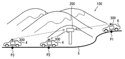
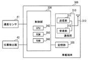
以下、本発明の実施形態を図面に基づいて説明する。第1実施形態の移動通信システム100は、図1に示すように、基地局200と車載端末300とを備える。車載端末300は、請求項の移動通信装置に相当する。
<First Embodiment>
Hereinafter, embodiments of the present invention will be described with reference to the drawings. The
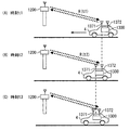
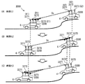
基地局200は、請求項の対象通信装置、通信装置に相当しており、所定の場所に固定されて、車載端末300と通信を行う。車載端末300は、移動体である車両4に搭載されている。ここでの車両4は自動車を意味する。図1の例では車両4は、道路5を走行している。図1には、地点P1、P2、P3の3つの地点にそれぞれ車両4を示している。これら3つの地点に位置する車両4は、同一の車両4が、順次、地点P1から地点P2、地点P3へ移動したことを表している。したがって、図1には、1台の車両4しか示されていないが、車載端末300は、複数の車両4にそれぞれ搭載される。また、基地局200も複数備えられていてもよい。
The
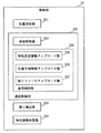
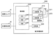
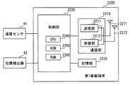
[基地局200の構成]
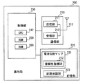
基地局200は、図2に示すように、通信部210、記憶部220、制御部230を備える。通信部210は、送信部211、受信部212、アンテナ213を備える。送信部211は、制御部230から入力される種々の信号を変調および増幅し、アンテナ213を介して外部に送信する。本実施形態の送信部211は、アクセス方式をOFDMA(frequency-division multiple access)とし、変調方式を、位相偏移変調、直交振幅変調から選択した方式とする。受信部212は、アンテナ213が受信した信号を復調し、復調した信号を制御部230に入力する。
[Configuration of Base Station 200]
As illustrated in FIG. 2, the
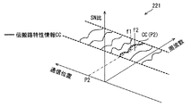
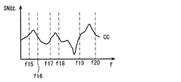
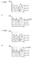
記憶部220は、書き込み可能になっており、電波伝搬マップ221と道路地図データベース223が記憶されている。電波伝搬マップ221は、種々の通信位置における伝搬路特性情報CCを格納したデータベースである。伝搬路特性情報CCは、OFDMにおいて推定が行われている伝搬路特性を表した情報である。本実施形態の伝搬路特性情報CCは、伝搬路の周波数特性を意味しており、周波数に対する強度と位相の特性である。図3には、伝搬路特性情報CCとして、種々の通信位置における、周波数とSN比の関係を例示している。電波伝搬マップ221により、種々の通信位置において、どの周波数のSN比がよいかなど分かる。なお、この電波伝搬マップ221は、車載端末300の型式別に作成されている。
The
車載端末300の型式別に電波伝搬マップ221が作成されている理由は、車載端末300の型式が異なれば、アンテナ特性が、車載端末300が備えるアンテナ313と異なるからである。なお、本実施形態において、アンテナ313は、請求項の参照アンテナおよび選択リソース用アンテナの双方として機能する。車載端末300の型式別に作成されていることにより、電波伝搬マップ221は、車載端末300のアンテナ313別に作成されていることになる。加えて、このアンテナ313が参照アンテナとして機能するので、電波伝搬マップ221は、複数の参照アンテナ別に作成されていることになる。また、車載端末300の型式がアンテナ決定情報に相当する。
The reason why the radio
車載端末300の型式別に電波伝搬マップ221を作成することで、アンテナ特性が同じアンテナで取得した伝搬路特性情報CCに基づいて電波伝搬マップ221を作成することができる。ただし、アンテナ特性が同じでなくても、選択リソース用アンテナとアンテナ特性が共通する参照アンテナを用いて基地局200との通信で取得した伝搬路特性情報CCに基づいて、電波伝搬マップ221を作成してもよい。アンテナ特性は、具体的には、設置状態での指向性や感度、あるいはそれらに影響を与える特徴により定まる。たとえば、アンテナ形式はアンテナ特性を定める一要素である。アンテナ形式は、アンテナ種別と言われることもある。同じアンテナ形式のアンテナであっても設置状態が異なればアンテナ特性は一般に異なる。例えば同一形式のアンテナを車両のルーフ上に設置した場合と室内に設置した場合では、指向性が変化するためにアンテナ特性が共通とはならない。また、アンテナの姿勢をアンテナ特性に含ませてもよい。
By creating the radio
アンテナ形式やアンテナ姿勢が同じでなくても、それらが類似していれば、アンテナ特性が共通しているとしてよい。どの程度の相違までをアンテナ特性が共通しているとするかは、要求される精度に応じて、適宜、設定すればよい。 Even if the antenna type and the antenna attitude are not the same, the antenna characteristics may be common if they are similar. To what extent the antenna characteristics are assumed to be common may be appropriately set according to the required accuracy.
また、この電波伝搬マップ221は、信頼性指標データベース222を備えている。信頼性指標データベース222は、電波伝搬マップ221に含まれている各伝搬路特性情報CCに対する信頼性指標についてのデータベースである。信頼性指標は、対応する伝搬路特性情報CCがどの程度信頼できるかを表す指標である。本実施形態では、信頼性指標は、伝搬路特性情報CCがどの程度再現するかを表す再現性指標に基づいて定まる。
The radio
再現性指標は、実質的に同じ通信位置において複数回取得した伝搬路特性情報CCの分布の広がりを表す値であり、分布の広がりが広いほど再現性指標は、再現性が低いことを意味する値になる。どの程度の位置の違いまでを実質的に同じとするかは、要求される精度に応じて、適宜、設定すればよい。 The reproducibility index is a value indicating the spread of the distribution of the channel characteristic information CC acquired a plurality of times at substantially the same communication position. The wider the spread of the distribution, the lower the reproducibility index is. Value. To what extent the difference in position is substantially the same may be set as appropriate according to the required accuracy.
信頼性指標は、たとえば、誤りが発生したリソースについて、再現性指標を、誤りが発生するほど低下させた値である。道路地図データベース223は、デジタル形式で道路地図を表したデータベースである。
The reliability index is, for example, a value obtained by reducing the reproducibility index for an errored resource as the error occurs. The
制御部230は、CPU242、ROM250、RAM260を備えたコンピュータであり、CPU242は、RAM260の一時記憶機能を利用しつつ、ROM250などの非遷移的実体的記録媒体(non-transitory tangible storage medium)に記憶されているプログラムを実行する。これにより、制御部230は、図4に示す各部として機能する。また、制御部230が、これらの機能を実行すると、プログラムに対応する方法が実行される。なお、制御部230が実行する機能の一部または全部を、一つあるいは複数のIC等によりハードウェア的に構成してもよい。
The
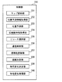
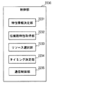
[制御部230の構成]
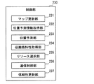
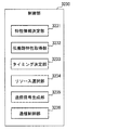
図4に示すように制御部230は、マップ更新部231、位置予測情報取得部232、位置予測部233、伝搬路特性取得部234、リソース選択部235、通信制御部236、信頼性更新部237を備える。
[Configuration of Control Unit 230]
As illustrated in FIG. 4, the
まず、マップ更新部231を説明する。基地局200は、周期的に参照信号Rを周囲に送信している。参照信号Rは、請求項の伝搬路推定用信号である。参照信号Rは、具体的には振幅と位相が既知であるパイロット信号、あるいはパイロット信号を一部に含む信号であり、すべてのサブチャネルに既知の信号が割り当てられた信号である。車載端末300は、この参照信号Rを受信すると、受信した参照信号Rの受信状態をもとに、伝搬路特性情報CCを決定する。
First, the
車載端末300は、決定した伝搬路特性情報CCを参照信号Rの受信時位置および車載端末300の型式とともに基地局200に非同期でアップロードする。基地局200の受信部212がこの伝搬路特性情報CCなどを受信すると、マップ更新部231は、受信部212から、伝搬路特性情報CC、受信時位置、車載端末300の型式を取得する。そして、取得した型式に基づいて更新する電波伝搬マップ221を特定し、特定した電波伝搬マップ221を、受信部212から取得した伝搬路特性情報CCと受信時位置とを用いて更新する。更新方法は、一例としては、取得した受信時位置に対応する電波伝搬マップ221における伝搬路特性情報CCと、取得した伝搬路特性情報CCとを、これまでに取得した伝搬路特性情報CCの数に応じて加重平均する方法がある。
The in-
次に、位置予測情報取得部232を説明する。後述するように、車載端末300は位置予測情報を基地局200に送信する。位置予測情報は、位置予測情報を車載端末300が送信する時点におけるアンテナ313の位置(以下、アップロード時位置)と、アップロード時点での車載端末300の移動速度と、車載端末300のIDと、車載端末300の型式とを含む。アップロード時位置と移動速度とを含むことにより、アップロード時点以後のアンテナ313の位置を予測することができる。また、位置予測情報に、車載端末300の進行方向が含まれていてもよい。ただし、進行方位は、アップロード時位置の時間変化により予測することができる。また、アップロード時位置の時間変化に加えて道路が延びる方向を用いると、より精度よく進行方位を予測することができる。よって、位置予測情報に進行方向が含まれていることは必須ではない。この位置予測情報は、基地局200の受信部212に受信される。位置予測情報取得部232は、受信部212から位置予測情報を取得する。
Next, the position prediction
位置予測部233は、位置予測情報取得部232が取得した位置予測情報に基づいて、車載端末300のアンテナ313の今後の予測位置を逐次決定する。詳しくは、位置予測情報に含まれている車載端末300の移動速度と、位置予測情報を受信した時点からの経過時間とから、車載端末300が位置予測情報をアップロードした時点から車載端末300が移動した移動距離を算出する。この移動距離だけ、アップロード時位置から車載端末300の移動方向に移動させた位置が、予測位置である。なお、車載端末300の移動方向は、同じ車載端末300から逐次取得する位置予測情報から定まるその車載端末300の移動軌跡に基づいて決定してもよい。また、位置予測情報に車載端末300の進行方向が含まれている場合には、その進行方向を車載端末300の移動方向としてもよい。
The
伝搬路特性取得部234は、位置予測部233が予測した予測位置を通信位置とし、この通信位置に対応付けて、この通信位置における伝搬路特性情報CCを、電波伝搬マップ221から取得する。位置予測情報には車載端末300の型式が含まれており、また、電波伝搬マップ221も車載端末300の型式別に作成されている。したがって、伝搬路特性情報CCを取得する電波伝搬マップ221は、位置予測情報に含まれている車載端末300の型式と同じ電波伝搬マップ221とする。図3には、一例として、地点P2を予測位置としたときに電波伝搬マップ221から取得する伝搬路特性情報CC(P2)を、実線に点線を重ねた表示で示している。
The propagation path
リソース選択部235は、伝搬路特性取得部234が取得した伝搬路特性情報CCに基づいて、位置予測部233が予測した予測位置(すなわち将来の通信位置)において、車載端末300との通信に用いるリソースを選択する。たとえば、図3に示すように、伝搬路特性情報CC(P2)は、周波数f1からf2の間のSN比が高い。したがって、周波数f1からf2の間の周波数を使用するサブキャリアを、車載端末300が通信位置に位置する時刻が属するタイムスロットにおいて、車載端末300との通信に使用する周波数リソースとして選択する。これにより、あるタイムスロット(すなわち時間リソース)における周波数リソースが選択される。
The
なお、伝搬路特性情報CCに対応する信頼性指標も用いてリソースを選択する。信頼性指標が相対的に低い周波数リソースについては、信頼性が低い分、相対的にSN比を小さい値に修正して、周波数リソースを選択する。 Note that a resource is selected using a reliability index corresponding to the propagation path characteristic information CC. For frequency resources with a relatively low reliability index, the frequency resources are selected by correcting the SN ratio to a relatively small value as the reliability is low.
上記説明は、1つの車載端末300についてのみ伝搬路特性情報CCを取得した場合の説明であったが、複数の車載端末300についての伝搬路特性情報CCを取得した場合には、リソース割り当てを最適化する必要がある。
The above description is a case where the propagation path characteristic information CC is acquired for only one in-
最適化は、たとえば、1つ以上の車載端末300に対する電波減衰が一定以下(すなわちSN比が一定以上)となる時間および周波数リソースの総量あるいは平均が、最大となるようにする。なお、伝搬路特性を取得した後、その伝搬路特性に基づいて周波数リソースを選択する方法はLTEセルラシステム等の既存システムにおいて用いられている方法と同じでよい。
The optimization is performed, for example, so that the total amount or the average of time and frequency resources when the radio wave attenuation for one or more in-
リソース選択部235は、予測位置、すなわち、まだ車載端末300が到達していない位置において車載端末300との通信に用いるリソースを選択している。したがって、車載端末300のアンテナ313が予測位置(すなわち通信位置)に位置する前にリソースを選択していることになる。
The
通信制御部236は、車載端末300の位置を位置予測情報に基づいて逐次決定しつつ、その位置におけるリソースを、リソース選択部235が選択したリソースとして、送信部211を制御して車載端末300との通信を行う。
The
この通信は、送信部211において説明したように、変調方式を、位相偏移変調、直交振幅変調から選択することができる。位相偏移変調には、BPSK、QPSKがあり、直交振幅変調には、16QAM、64QAM、256QAMなどがある。これらBPSK、QPSK、16QAM、64QAM、256QAMは、通信速度と信頼性が相反する関係にあり、通信速度が速いほど信頼性は低下する。したがって、選択したリソースの信頼性をSN比で判断し、信頼性が高いほど、通信速度が高い変調方式を選択する。換言すれば、信頼性が低いほど、通信速度が低い変調方式を選択する。また、信頼性が低いほど、冗長性を高く(すなわち符号化率を小さく)してもよい。図1の例では、車両4が地点P2に位置しているときに、基地局200は、選択した周波数リソースで車載端末300に信号を送信している。
In this communication, as described in the
通信制御部236の上記説明は、下りリンク時の説明であるが、通信制御部236は、上りリンクに対しても、リソース選択部235が選択したリソースで、車載端末300と通信することもできる。
The above description of the
上りリンクにおいて、リソース選択部235が選択したリソースを用いる場合には、通信制御部236は、車載端末300が通信位置に位置する前に、リソース選択部235が選択したリソースを表す信号を、車載端末300に送信すればよい。
In the uplink, when the resource selected by the
車載端末300は基地局200が送信した信号を受信すると、信号の誤りを判定して、誤りの発生したリソースおよびそのときのアンテナ313の位置とを含んでいる誤りリソース情報を基地局200にアップロードする。
When the in-
信頼性更新部237は、この誤りリソース情報を基地局200の受信部212が受信すると、受信部212から、その誤りリソース情報を取得する。そして、取得した誤りリソース情報に基づいて、信頼性指標データベース222の信頼性指標のうち、誤りリソース情報により定まる通信位置、周波数リソースの信頼性指標を、所定量あるいは所定割合、低下させる。
When the
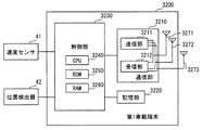
[車載端末300の構成]
車載端末300は、図5に示すように、通信部310、記憶部320、制御部330を備える。通信部310は、送信部311、受信部312、アンテナ313を備える。送信部311は、制御部330から入力される種々の信号を変調および増幅し、アンテナ313を介して外部に送信する。本実施形態の送信部311は、アクセス方式をSC−FDMAとし、変調方式を、位相偏移変調、直交振幅変調から選択した方式とする。受信部312は、アンテナ313が受信した信号を復調し、復調した信号を制御部330に入力する。アンテナ313は、前述したように、請求項の参照アンテナおよび選択リソース用アンテナの双方として機能する。記憶部320は、制御部330に制御されて種々の情報が書き込み可能である。
[Configuration of in-vehicle terminal 300]
As shown in FIG. 5, the in-
制御部330は、CPU342、ROM350、RAM360を備えたコンピュータであり、CPU342が、RAM360の一時記憶機能を利用しつつ、ROM350などの非遷移的実体的記録媒体に記憶されているプログラムを実行する。これにより、制御部330は、図6に示す各部として機能する。また、制御部330が、これらの機能を実行すると、プログラムに対応する方法が実行される。なお、制御部330が実行する機能の一部または全部を、一つあるいは複数のIC等によりハードウェア的に構成してもよい。
The
速度センサ41は、車載端末300の移動速度を逐次検出し、検出した移動速度を制御部330に入力する。この速度センサ41には、車両4の速度を検出する車速センサを用いることができる。
The
位置検出器42は、GNSS(Global Navigation Satellite System)が備える航法衛星が送信する航法信号を受信するGNSS受信機を備えている。このGNSS受信機が受信した航法信号に基づいて現在位置を逐次検出する。そして、検出した現在位置を逐次、制御部330に入力する。
The
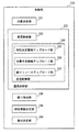
[制御部330の構成]
図6に示すように制御部330は、位置決定部331、通信制御部332、誤り検出部338、特性情報決定部339を備える。位置決定部331は、位置検出器42が検出した現在位置を逐次取得することで、アンテナ313の現在位置を逐次決定する。なお、位置検出器42が検出する現在位置は、その位置検出器42が配置されている位置であり、アンテナ313の現在位置ではない。そこで、アンテナ313の位置と位置検出器42の位置との差に基づいて、位置検出器42が検出する現在位置を補正して、アンテナ313の現在位置としてもよい。ただし、本実施形態では、アンテナ313が、参照アンテナおよび選択リソース用アンテナとして機能する。そのため、位置検出器42の位置を、参照アンテナの位置と選択リソース用アンテナの位置としても、参照アンテナの位置に選択リソース用アンテナが位置したことを判断する精度に影響はない。参照アンテナの位置誤差と選択リソース用アンテナの位置誤差が同等である場合には、位置検出器42が検出する現在位置を補正して、アンテナ313の現在位置とする必要はない。
[Configuration of Control Unit 330]
As illustrated in FIG. 6, the
通信制御部332は、受信制御部333と送信制御部334とを備える。受信制御部333は、基地局200から送信されアンテナ313が受信した信号のうち、自端末に割り当てられたリソースブロックの信号を復号する。どのリソースが自端末に割り当てられているかは、無線システムごとにあらかじめ決められた方法を用いて判断する。例えばLTEセルラシステムでは、各無線フレーム内の制御チャネル領域に収容される割当情報から判断する。アンテナ313は、基地局200のリソース選択部235が選択したリソースの信号を受信するために用いられているので、請求項の選択リソース用アンテナに相当する。
The
送信制御部334を説明する前に、誤り検出部338、特性情報決定部339を説明する。誤り検出部338は、自端末に割り当てられたリソースを用いて送信された信号に誤りがあるか否かを、誤り訂正符号等に基づく公知の誤り検出方法により検出する。
Before describing the
特性情報決定部339は、受信部312が基地局200から参照信号Rを受信し、受信部312からこの参照信号Rを取得すると、参照信号Rの受信状態をもとに、伝搬路特性情報CCを決定する。受信した参照信号Rをもとに伝搬路特性情報CCを推定する方法は、MIMO等で広く行われている方法と同じでよい。なお、伝搬路特性情報CCは、伝搬路状態あるいは伝搬路推定結果とも言われる。この伝搬路特性情報CCは、たとえば、周波数ごとのパワーと位相で表される。
When the
送信制御部334は、特性決定情報アップロード部335と、位置予測情報アップロード部336と、誤りリソースアップロード部337とを備える。特性決定情報アップロード部335は、参照信号Rの受信時位置と、特性情報決定部339が決定した伝搬路特性情報CCと、車載端末300の型式とを、送信部311から、基地局200にアップロードする。なお、アップロードするタイミングは、伝搬路特性情報CCを決定したタイミングには制約されない、非同期のタイミングでよい。図1の例では、車両4が地点P1に位置しているときに、車載端末300は、この伝搬路特性情報CCをアップロードしている。
The
特性決定情報アップロード部335がアップロードした伝搬路特性情報CCは、前述したように、基地局200が備える制御部230のマップ更新部231において、電波伝搬マップ221の更新に用いられる。したがって、アンテナ313は参照アンテナとして機能することになる。
The propagation path characteristic information CC uploaded by the characteristic determination information upload
位置予測情報アップロード部336は、前述した位置予測情報を、逐次、基地局200にアップロードする。位置予測情報は、前述したように、位置予測情報を車載端末300が送信する時点におけるアンテナ313の位置であるアップロード時位置と、アップロード時点での車載端末300の移動速度と、車載端末300のIDと、車載端末300の型式とを含んでいる。
The position prediction information upload
誤りリソースアップロード部337は、誤り検出部338が誤りを検出した信号の伝送に用いられたリソースを表す誤りリソース情報を基地局200にアップロードする。誤りリソース情報は、誤りが発生した周波数リソースと、その誤りが発生したときの位置を含んだ情報である。
The error resource upload
誤りリソース情報をアップロードするタイミングも、非同期のタイミングでよい。図1の例では、車両4が地点P3に位置しているときに、車載端末300は、地点P2で検出した誤りについての誤りリソース情報をアップロードしている。
The timing for uploading the error resource information may be asynchronous. In the example of FIG. 1, when the
[第1実施形態のまとめ]
以上、説明した第1実施形態では、基地局200は、過去にアンテナ313で基地局200と通信したときの伝搬路特性情報CCを、予測位置すなわち将来の通信位置に対応付けて、電波伝搬マップ221から取得する伝搬路特性取得部234を備える。
[Summary of First Embodiment]
As described above, in the first embodiment described above, the
将来の通信位置に対応付けて伝搬路特性情報CCを取得することにより、リソース選択部235は、通信位置において車載端末300と基地局200との通信に用いるリソースを、車載端末300のアンテナ313が通信位置に位置する前に選択することができる。これにより、リソース選択部235が選択したリソースを通信位置で用いて通信することができるので、信頼性の高い通信が行えるようになる。
By acquiring the propagation path characteristic information CC in association with the future communication position, the
<第2実施形態>
次に、第2実施形態を説明する。この第2実施形態以下の説明において、それまでに使用した符号と同一番号の符号を有する要素は、特に言及する場合を除き、それ以前の実施形態における同一符号の要素と同一である。また、構成の一部のみを説明している場合、構成の他の部分については先に説明した実施形態を適用できる。
Second Embodiment
Next, a second embodiment will be described. In the following description of the second embodiment, elements having the same reference numerals as those used so far are the same as elements having the same reference numerals in the previous embodiments unless otherwise specified. Further, when only a part of the configuration is described, the above-described embodiment can be applied to the other parts of the configuration.
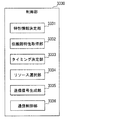
第2実施形態では、図7に示すように、制御部230は、第1実施形態の構成に加えて、距離決定部238、特性変化決定部239、特性変化補償部240を備える。
In the second embodiment, as illustrated in FIG. 7, the
距離決定部238は、位置予測情報に含まれている車載端末300の移動速度を、位置予測情報を受信した受信部212から取得する。この移動速度に、予め設定されている、1通信あたりの通信時間を乗じて、1通信期間中の移動距離を決定する。
The
特性変化決定部239は、通信開始時の通信位置を、位置予測部233の予測結果に基づいて決定する。また、その通信開始時の通信位置に、距離決定部238が決定した1通信期間中の移動距離を加えることで、通信終了時の通信位置を決定する。そして、通信開始時の通信位置における伝搬路特性情報CCと、通信終了時の通信位置における伝搬路特性情報CCとを、それぞれ、電波伝搬マップ221から取得する。
The characteristic
次いで、通信開始時の通信位置における伝搬路特性情報CCに対する通信終了時の通信位置における伝搬路特性情報CCの比率を、通信期間における伝搬路特性情報CCの変化とする。 Next, the ratio of the propagation path characteristic information CC at the communication position at the end of communication to the propagation path characteristic information CC at the communication position at the start of communication is defined as a change in the propagation path characteristic information CC during the communication period.
特性変化補償部240は、特性変化決定部239が決定した、通信期間における伝搬路特性情報CCの変化が通信に与える影響を軽減させる補償を通信信号に対して行う。ここで、通信信号は、送信信号および受信信号を含む意味である。この補償を行うためには、電波伝搬マップ221が必要であることから、電波伝搬マップ221を備えている側が送信側であれば、通信信号は送信信号であり、電波伝搬マップ221を受信側が備えていれば、通信信号は受信信号である。
The characteristic
本実施形態では、基地局200が電波伝搬マップ221を備えている。したがって、基地局200が信号を送信する場合には、基地局200が送信する信号に対して補償を行い、基地局200が電波を受信する場合には、基地局200が受信する信号に対して補償を行う。
In the present embodiment, the
補償の方法は、たとえば、送信開始時に対して送信終了時には、SN比が半分になることが、特性変化決定部239により決定されている場合には、送信終了時の信号の送信パワーを送信開始時の送信パワーの2倍にして送信する。また、位相についても、送信開始時に対して送信終了時には、位相が90度進むことが、特性変化決定部239により決定されている場合には、送信終了時の信号の位相を送信開始時の位相に対して90度遅らせて送信する。なお、送信開始時と送信終了時の間の送信パワー、位相は、内挿により決定すればよい。
As a compensation method, for example, when the characteristic
この例とは異なり、上りリンク、すなわち、車載端末300が送信する信号に対して補償を行うこともできる。上りリンクの信号に対して補償を行う場合、アンテナ213が受信した信号を復調する前に、パワーと位相を補償する。
Unlike this example, it is also possible to compensate for an uplink, that is, a signal transmitted by the in-
さらに、車載端末300が、基地局200から電波伝搬マップ221をダウンロードするなどして、電波伝搬マップ221を備えていれば、車載端末300が距離決定部238、特性変化決定部239、特性変化補償部240を備えていてもよい。
Furthermore, if the in-
第2実施形態のように、通信開始時の伝搬路特性情報CCと通信終時の伝搬路特性情報CCを比較して、伝搬路特性情報CCの変化が通信に与える影響を軽減するように補償を行えば、より通信の信頼性が向上する。 As in the second embodiment, the propagation path characteristic information CC at the start of communication is compared with the propagation path characteristic information CC at the end of the communication, and compensation is performed so as to reduce the influence of changes in the propagation path characteristic information CC on the communication. If this is performed, the reliability of communication is further improved.
<第3実施形態>
第3実施形態では、車載端末300は、基地局200の記憶部220が記憶している電波伝搬マップ221をダウンロードして記憶部320に記憶する。第3実施形態では、記憶部320は、請求項のダウンロードデータ記憶部に相当する。
<Third Embodiment>
In the third embodiment, the in-
記憶部320に記憶する電波伝搬マップ221は、基地局200の記憶部220が記憶している電波伝搬マップ221の全部であってもよいが、車載端末300の現在位置周辺に限定してもよい。
The radio
図8に示すように、第3実施形態では、車載端末300の制御部330は、第1実施形態の構成に加えて、差分決定部340を備える。
As shown in FIG. 8, in 3rd Embodiment, the
差分決定部340は、特性情報決定部339が決定した伝搬路特性情報CCと、記憶部320に記憶されている電波伝搬マップ221において特性情報決定部339が決定した伝搬路特性情報CCに対応する部分との差分である伝搬路特性差分を決定する。この伝搬路特性差分は、通信位置毎の1つの伝搬路特性情報CCを単位として決定してもよいし、通信位置毎の1つの伝搬路特性情報CCを、さらに、複数の周波数帯に分けて比較して決定してもよい。
The
第3実施形態における特性決定情報アップロード部335は、差分決定部340が決定した伝搬路特性差分を特性決定情報としてアップロードする。このようにすることで、アップロードするデータ量が少なくなるので、通信帯域を圧迫してしまうことを抑制できる。
The characteristic determination information upload
<第4実施形態>
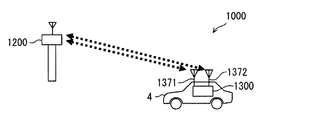
第4実施形態の移動通信システム1000は、図9に示すように、請求項の対象通信装置に相当する基地局1200と、請求項の移動通信装置に相当する車載端末1300を備える。これら基地局1200と車載端末1300は、それぞれ複数備えられていてもよい。
<Fourth embodiment>
As shown in FIG. 9, the
[車載端末1300の構成]
図9に示すように、車載端末1300は、前側アンテナ1371と、後側アンテナ1372を備えている。これらのアンテナ1371、1372は、同じ構造のアンテナであり、車両4の屋根に、互いに車両4の進行方向に前後関係になるように、かつ、互いに同じ高さに配置されている。前側アンテナ1371は参照アンテナとして機能し、後側アンテナ1372は選択リソース用アンテナとして機能する。
[Configuration of in-vehicle terminal 1300]
As shown in FIG. 9, the in-
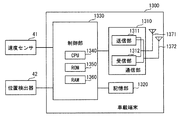
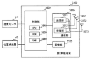
図10に示すように、車載端末1300は、通信部1310、記憶部1320、制御部1330を備える。通信部1310は、送信部1311、受信部1312を備えており、これら送信部1311、受信部1312は、2つのアンテナ1371、1372を切り替えて用いて送信、受信を行う。アンテナの切り替え機能を有する以外は、送信部1311、受信部1312は、第1実施形態の送信部311、受信部312と同じ機能を備える。
As illustrated in FIG. 10, the in-
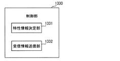
制御部1330は、図11に示すように、機能として、特性情報決定部1331、受信情報送信部1332を備える。まず、特性情報決定部1331を説明する。第4実施形態でも、基地局1200は、周期的に参照信号Rを送信している。参照信号Rは、前側アンテナ1371でも後側アンテナ1372でも受信できる。
As illustrated in FIG. 11, the
特性情報決定部1331は、前側アンテナ1371、後側アンテナ1372が受信した参照信号Rを受信部1312から取得し、第1実施形態の特性情報決定部339と同様にして、伝搬路特性情報CCを決定する。以下、前側アンテナ1371が受信した参照信号Rから決定した伝搬路特性情報CCを前側アンテナ伝搬路特性情報CCAとし、後側アンテナ1372が受信した参照信号Rから決定した伝搬路特性情報CCを後側アンテナ伝搬路特性情報CCBとする。
The characteristic
受信情報送信部1332は、特性情報決定部1331が決定した前側アンテナ伝搬路特性情報CCAと、後側アンテナ伝搬路特性情報CCBと、参照信号Rを受信したときの車載端末1300の移動速度と、前側アンテナ1371と後側アンテナ1372との距離と、車載端末300のIDとを、送信部1311から基地局1200に送信する。
The reception
[基地局1200の構成]
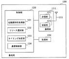
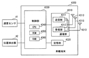
基地局1200は、ハードウェア構成は第1実施形態の基地局200と同じであり、図12に示すように、基地局1200は、第1実施形態の基地局200が備えるものと同じハードウェア構成である通信部1210、記憶部1220、制御部1230を備える。したがって、通信部1210が備える送信部1211、受信部1212、アンテナ1213は、図2の通信部210が備える送信部211、受信部212、アンテナ213と同じである。
[Configuration of Base Station 1200]
The
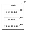
制御部1230は、図2の制御部230とは機能が相違する。図12に示すように、制御部1230は、伝搬路特性取得部1231、リソース選択部1232、タイミング決定部1233、通信制御部1234を機能として備える。
The
伝搬路特性取得部1231は、車載端末1300の受信情報送信部1332が送信し、受信部1212が受信した前側アンテナ伝搬路特性情報CCAおよび後側アンテナ伝搬路特性情報CCBを、受信部1212から取得する。また、取得時を、車載端末1300が受信位置(すなわち通信位置)に位置していたとする。つまり、前側アンテナ伝搬路特性情報CCAおよび後側アンテナ伝搬路特性情報CCBを、受信時の位置に対応付けることになる。
The propagation path
リソース選択部1232は、前側アンテナ1371が参照信号Rを受信した位置を通信位置とし、その通信位置において通信に用いるリソースを、伝搬路特性取得部1231が取得した前側アンテナ伝搬路特性情報CCAに基づいて決定する。
The
リソース選択部1232は、さらに、後側タイミング後期間におけるリソースを決定する。後側タイミング後期間は、次に説明するタイミング決定部1233が決定する後側通信タイミング以降であって、後側通信タイミングにおける前側アンテナ1371の位置に後側アンテナ1372が到達すると予測されるまでの期間である。
The
なお、後側通信タイミングの決定には、車載端末300の移動速度を用いる。この移動速度とともに取得した前側アンテナ伝搬路特性情報CCAに対応する参照信号Rを送信したタイミングを前側通信タイミングとする。前側通信タイミングは図13、図14における時刻t1であり、後側通信タイミングは図13、図14における時刻t2であり、後側タイミング後期間の一例は、図13、図14における時刻t3である。
Note that the moving speed of the in-
後側タイミング後期間では、伝搬路特性情報CCが、前側通信タイミングおよび後側通信タイミングで伝搬路特性取得部1231がそれぞれ取得した前側アンテナ伝搬路特性情報CCAの間になると予想できる。この予想できる伝搬路特性情報CCに基づいて、後側タイミング後期間におけるリソースを決定する。
In the period after the rear timing, it can be expected that the propagation path characteristic information CC is between the front antenna propagation path characteristic information CCA acquired by the propagation path
タイミング決定部1233は、受信部1212が受信した車載端末1300の移動速度に基づいて、後側アンテナ1372の位置が、前側アンテナ1371が参照信号Rを受信した位置(すなわち上述の通信位置)となるタイミングを決定する。このタイミングが、前述の後側通信タイミングである。
In the
通信制御部1234は、前述した参照信号Rを送信部211から周期的に送信する。また、タイミング決定部1233が決定した後側通信タイミングで、リソース選択部1232が、後側通信タイミングにおいて使用するリソースとして選択したリソースで車載端末1300と通信する。通信は具体的には送信であり、選択したリソースで任意の信号を送信する。また、この任意の信号に加えて、参照信号Rを全サブチャネルを使用して送信する。この通信制御部1234は請求項の対象装置側通信制御部に相当する。
The
通信制御部1234は、さらに、後側タイミング後期間で、リソース選択部1232が、後側タイミング後期間において使用するリソースとして選択したリソースで車載端末1300と通信する。
Further, the
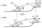
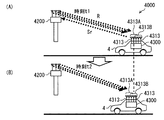
[第4実施形態の通信例]
図13(A)に示す時刻t1において、基地局1200は参照信号R(t1)を送信しており、車載端末1300はその参照信号R(t1)を受信している。その時刻t1の後、車載端末1300の特性情報決定部1331は、前側アンテナ1371が受信した参照信号R(t1)を取得して、前側アンテナ伝搬路特性情報CCAを決定する。そして、受信情報送信部1332は、時刻t2よりも前に、その前側アンテナ伝搬路特性情報CCAと、移動速度と、車載端末300のIDとを基地局1200に送信する。基地局1200の伝搬路特性取得部1231は、これら前側アンテナ伝搬路特性情報CCAなどを、受信部1212から取得する。
[Communication Example of Fourth Embodiment]
At time t1 shown in FIG. 13A, the
図14(A)に、図13(A)の状態において伝搬路特性取得部1231が取得する前側アンテナ伝搬路特性情報CCAを例示している。この図に示す前側アンテナ伝搬路特性情報CCAは、横軸は周波数であり、縦軸がSN比を表す。図14(A)に示す前側アンテナ伝搬路特性情報CCAは、周波数によりSN比が異なる。
FIG. 14A illustrates the front antenna propagation path characteristic information CCA acquired by the propagation path
そこで、基地局1200のリソース選択部1232は、SN比のよい周波数チャネルを、通信位置において用いるリソースとして選択する。図14(A)では、周波数f3〜f4、f5〜f6、f7〜f8がSN比がよい周波数帯になるので、これらの周波数帯を利用する周波数チャネルを、通信位置において用いるリソースとして選択する。
Therefore, the
また、タイミング決定部1233は、車載端末1300の移動速度に基づいて後側通信タイミングを決定する。後側通信タイミングは、後側アンテナ1372が、前側アンテナ1371の通信位置に位置するタイミングである。この後側通信タイミングは、前側アンテナ1371と後側アンテナ1372との距離を、車載端末1300の移動速度で割ることにより算出できる時間を、前側アンテナ伝搬路特性情報CCAに対応する参照信号Rを送信した時刻に加えた時刻である。
Further, the
この後側通信タイミングで、基地局1200は車載端末1300と通信する。図14(B)に示す時刻t2は、この後側通信タイミングである。時刻t2では、通信制御部1234は、参照信号Rを送信している。車載端末1300の制御部1330の特性情報決定部1331、受信情報送信部1332は、前側アンテナ伝搬路特性情報CCA、後側アンテナ伝搬路特性情報CCBなどを決定し、それらを送信部1311から基地局1200に送信する。
At this rear communication timing, the
図14(B)において、点線で示す前側アンテナ伝搬路特性情報CCA(t1)は、時刻t1における前側アンテナ伝搬路特性情報CCAである。また、実線で示す前側アンテナ伝搬路特性情報CCA(t2)は、時刻t2における前側アンテナ伝搬路特性情報CCAである。また、もう1本の実線で示すCCB(t2)は、時刻t2における後側アンテナ伝搬路特性情報CCBである。 In FIG. 14B, front antenna propagation path characteristic information CCA (t1) indicated by a dotted line is front antenna propagation path characteristic information CCA at time t1. Also, the front antenna propagation path characteristic information CCA (t2) indicated by the solid line is the front antenna propagation path characteristic information CCA at time t2. CCB (t2) indicated by another solid line is the rear antenna propagation path characteristic information CCB at time t2.
図14(B)に示す後側アンテナ伝搬路特性情報CCB(t2)は、前側アンテナ1371が参照信号Rを受信した位置で、後側アンテナ1372が参照信号Rを受信して決定した伝搬路特性情報CCである。したがって、後側アンテナ伝搬路特性情報CCB(t2)は、前側アンテナ伝搬路特性情報CCA(t1)に類似している。このことから、時刻t2において、リソース選択部1232が選択したリソースで基地局1200と車載端末1300とが通信すると、良好なSN比で通信できることが分かる。
The rear antenna propagation path characteristic information CCB (t2) shown in FIG. 14B is the propagation path characteristic determined by the
さらに、リソース選択部1232は、前述した後側タイミング後期間に用いるリソースを決定する。後側タイミング後期間は、前述したように、後側通信タイミング以降であって、後側通信タイミングにおける前側アンテナ1371の位置に、後側アンテナ1372が到達すると予測されるまでの期間である。図13(C)は、後側タイミング後期間における車載端末1300の位置を例示している。
Furthermore, the
図13(C)における後側アンテナ1372の位置は、図13(A)に示す時刻t1における前側アンテナ1371の位置と、図13(B)に示す時刻t2における前側アンテナ1371の位置の間である。したがって、図14(C)に示すように、時刻t3における後側アンテナ伝搬路特性情報CCB(t3)の予想値は、時刻t1における前側アンテナ伝搬路特性情報CCA(t1)と、時刻t2における前側アンテナ伝搬路特性情報CCA(t2)の間であると予想できる。図13(C)に示す後側アンテナ伝搬路特性情報CCB(t3)は、前側アンテナ伝搬路特性情報CCA(t1)と前側アンテナ伝搬路特性情報CCA(t2)を、時刻t1における前側アンテナ1371の位置から時刻t3における後側アンテナ1372の位置までの距離と、時刻t3における後側アンテナ1372の位置から時刻t2における前側アンテナ1371の位置までの距離との比率に基づいて、前側アンテナ伝搬路特性情報CCA(t1)と前側アンテナ伝搬路特性情報CCA(t2)を加重平均して求めることができる。あるいは、必要とされる精度によっては、加重平均ではなく、前側アンテナ伝搬路特性情報CCA(t1)と前側アンテナ伝搬路特性情報CCA(t2)を単純平均して後側アンテナ伝搬路特性情報CCB(t3)を求めてもよい。
The position of the
リソース選択部1232は、このようにして求めた後側タイミング後期間における後側アンテナ伝搬路特性情報CCBに基づいて、後側タイミング後期間において用いるリソースを決定する。図14(C)の例では、後側アンテナ伝搬路特性情報CCB(t3)の予想値は、周波数f9〜f10、f11〜f12、f13〜f14がSN比がよい周波数帯になる。そこで、これらの周波数帯を利用する周波数チャネルを、時刻t3において用いるリソースとして選択する。
The
そして、通信制御部1234は、このリソースで、時刻t3において、車載端末1300のIDを含む信号を送信して、車載端末1300と通信する。これにより、時刻t3でも、良好なSN比で通信できる。
And the
<第5実施形態>
第5実施形態の移動通信システムは、ハードウェア構成は第4実施形態と同じである。車載端末1300の制御部1330は、第4実施形態と同様、特性情報決定部1331と受信情報送信部1332を備える。
<Fifth Embodiment>
The mobile communication system according to the fifth embodiment has the same hardware configuration as that of the fourth embodiment. The
ただし、第5実施形態において、受信情報送信部1332は、第4実施形態で送信した種々の情報に加えて、参照信号Rを受信したときの現在位置も、基地局1200に送信する。よって、第5実施形態では、受信情報送信部1332は、前側通信タイミングおよび後側通信タイミングでそれぞれ受信した参照信号Rからそれぞれ決定した前側アンテナ伝搬路特性情報CCA、後側アンテナ伝搬路特性情報CCBを、参照信号Rを受信したときの車載端末1300の移動速度、前側アンテナ1371と後側アンテナ1372との距離、車載端末300のIDとともに、送信部1311から基地局1200に送信する。
However, in the fifth embodiment, the reception
基地局1200は、図15に示すように、記憶部1220に、再現性指標データベース1224を備える。また、制御部1230は、図15に示すように再現性決定部1235をさらに備える。なお、図15に示す構成以外は、第4実施形態の基地局1200と同じであり、図15は、第4実施形態の基地局1200と同じ構成については図示を省略している。
As illustrated in FIG. 15, the
再現性指標データベース1224は、次に説明する再現性決定部1235が決定した再現性指標を、地点に対応付けているデータベースである。
The
再現性決定部1235は、前側アンテナ伝搬路特性情報CCAと、後側通信タイミングにおいて基地局1200が送信した参照信号Rから決定した後側アンテナ伝搬路特性情報CCBとを比較して、伝搬路特性情報CCの再現性を表す再現性指標を決定する。再現性指標は、たとえば次のようにして算出する。前側アンテナ伝搬路特性情報CCAが表すSN比と後側アンテナ伝搬路特性情報CCBが表すSN比との差の絶対値を各周波数で算出し、その差の絶対値の積分値が大きいほど、再現性が低いことを示す再現性指標とする。さらに、再現性決定部1235は、決定した再現性指標を通信位置に対応付け、その再現性指標と通信位置とに基づいて、再現性指標データベース1224を更新する。
The
また、第5実施形態では、通信制御部1234は、前側通信タイミングにおいて取得した車載端末1300の現在位置と移動速度とから、後側通信タイミングあるいは後側タイミング後期間における通信時の位置を決定する。そして、決定した通信時の位置と、再現性指標データベース1224とに基づいて、後側通信タイミングあるいは後側タイミング後期間における通信の信頼性に関するパラメータ設定を決定して、車載端末1300と通信する。
Moreover, in 5th Embodiment, the
信頼性に関するパラメータは、たとえば、符号化率である。符号化率が低いほど、すなわち、冗長性が高いほど、通信の信頼性は高いので、再現性指標が、再現性が低いことを示す値であるほど、符号化率を低くする。また、信頼性に関するパラメータとしては、変調速度がある。変調速度が速いほど通信の信頼性は低いので、再現性指標が、再現性が低いことを示す値であるほど、変調速度を遅くする。 The parameter relating to reliability is, for example, a coding rate. The lower the coding rate, that is, the higher the redundancy, the higher the reliability of communication. Therefore, the lower the coding rate is, the lower the coding rate is. Further, as a parameter related to reliability, there is a modulation speed. Since the reliability of communication is lower as the modulation speed is higher, the modulation speed is decreased as the reproducibility index is a value indicating that the reproducibility is lower.
これにより、第5実施形態では、後側通信タイミングあるいは後側タイミング後期間における通信の信頼性がより向上する。 Thereby, in 5th Embodiment, the reliability of the communication in a back side communication timing or a back side timing post-period improves more.
<第6実施形態>
第6実施形態に係る移動通信システム2000は、図16に示すように、第1車載端末2200と第2車載端末2300を備える。第1車載端末2200は車両6に搭載され、第2車載端末2300は車両4に搭載されている。これら第1車載端末2200、第2車載端末2300は、それぞれ複数備えられていてもよい。車両6は請求項の第1移動体に相当し、車両6に搭載されている第1車載端末2200は請求項の対象通信装置に相当する。車両4は請求項の第2移動体に相当し、車両4に搭載されている第2車載端末2300は請求項の移動通信装置に相当する。
<Sixth Embodiment>
The
まず、第2車載端末2300の構成を説明する。図17に示すように、第2車載端末2300は、ハードウェア構成は、第4実施形態の車載端末1300と同じである。
First, the configuration of the second in-
したがって、通信部2310は、送信部2311、受信部2312、前側アンテナ2371、後側アンテナ2372を備えている。これらは、図10の通信部1310が備える送信部1311、受信部1312、前側アンテナ1371、後側アンテナ1372と同じ構成である。前側アンテナ2371、後側アンテナ2372は、前側アンテナ1371、後側アンテナ1372と同様、車両4の屋根に、互いに車両4の進行方向に前後関係になるように、かつ、互いに同じ高さに配置されている。この第6実施形態では、前側アンテナ2371が参照アンテナであり、後側アンテナ2372が選択リソース用アンテナである。
Therefore, the
また、記憶部2320は、図10の記憶部1320と同じであり、制御部2330はCPU2340、ROM2350、RAM2360を備える。この制御部2330には、速度センサ41と位置検出器42から信号が入力される。
The
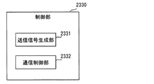
制御部2330の機能は図10の制御部1330とは相違しており、図18に示す機能を備える。すなわち、制御部2330は、送信信号生成部2331と通信制御部2332としての機能を備える。
The function of the
送信信号生成部2331は、送信部2311から送信する第2端末信号St2を周期的に生成する。第2端末信号St2は、参照信号Rと、第2車載端末2300の移動速度を示す信号と、アンテナ間距離を示す信号とを含むものである。第2車載端末2300の移動速度は、速度センサ41から取得した速度とする。また、アンテナ間距離は、前側アンテナ2371と後側アンテナ2372との間の距離である。なお、第1車載端末2200が、予めこのアンテナ間距離を記憶していれば、第2端末信号St2にアンテナ間距離を含ませる必要はない。
The transmission
通信制御部2332は、送信部2211を制御して、前側アンテナ2371から、送信信号生成部2331が生成した第2端末信号St2を送信する。図16(A)に示す時刻t1は、この状態を表している。第2端末信号St2を第1車載端末2200が受信すると、第1車載端末2200は、第2端末信号St2に含まれている参照信号Rに基づいて決定したリソースで、第2車載端末2300に第1端末信号St1を送信する。通信制御部2332は、受信部2312を制御して、第1端末信号St1を後側アンテナ2372で受信する。
The
次に、第1車載端末2200の構成を説明する。図19に示すように、第1車載端末2200のハードウェア構成は、第2車載端末2300と同じである。すなわち、第1車載端末2200は、通信部2210、記憶部2220、制御部2230を備える。これらは、第2車載端末2300が備える通信部2310、記憶部2320、制御部2330と同じ構成である。
Next, the configuration of the first in-
通信部2210は、送信部2211、受信部2212、対象装置前側アンテナ2271、対象装置後側アンテナ2272を備えている。これらは、第2車載端末2300の通信部2310が備える送信部2311、受信部2312、前側アンテナ2371、後側アンテナ2372と同じ構成である。対象装置前側アンテナ2271、対象装置後側アンテナ2272は、車両6の屋根に、互いに車両6の進行方向に前後関係になるように、かつ、互いに同じ高さに配置されている。また、対象装置前側アンテナ2271と対象装置後側アンテナ2272の間の距離は、前側アンテナ2371と後側アンテナ2372の間の距離と同じである。
The
また、制御部2230は、CPU2240、ROM2250、RAM2260を備え、制御部2230には、速度センサ41、位置検出器42からの信号が入力される。
The
制御部2230は図20に備える機能を備える。すなわち、制御部2230は、特性情報決定部2231、伝搬路特性取得部2232、リソース選択部2233、タイミング決定部2234、通信制御部2235としての機能を備える。
The
前述したように、第2車載端末2300は第2端末信号St2を送信する。特性情報決定部2231は、対象装置前側アンテナ2271で第2端末信号St2を受信できた場合に、受信時すなわち第2車載端末2300にとっては送信時に、第2車載端末2300が通信位置に位置していたとする。
As described above, the second in-
さらに、特性情報決定部2231は、受信した第2端末信号St2に含まれている参照信号Rに基づいて伝搬路特性情報CCを決定する。そして、決定した伝搬路特性情報CCを記憶部2220に記憶する。なお、本実施形態では伝搬路特性情報CCを記憶部2220に記憶するが、他の記憶部に伝搬路特性情報CCを記憶指定もよい。図21には、特性情報決定部2231が決定した伝搬路特性情報CCを例示している。
Furthermore, the characteristic
伝搬路特性取得部2232は、記憶部2220から伝搬路特性情報CCを取得する。リソース選択部2233は、特性情報決定部2231が決定した通信位置において通信に用いるリソースを、伝搬路特性取得部2232が取得した伝搬路特性情報CCに基づいて選択する。リソースの意味、および、リソースの選択方法は、第1実施形態のリソース選択部235と同じである。図21に例示した伝搬路特性情報CCに基づいて通信に用いる周波数リソースを選択する場合、図21では、周波数f15〜f16、f17〜f18、f19〜f20がSN比がよい周波数帯になる。そこで、これらの周波数帯を利用する周波数チャネルを、通信位置において用いるリソースとして選択する。
The propagation path
タイミング決定部2234は、第2車載端末2300が備える後側アンテナ2372が、前側アンテナ2371が第2端末信号St2を送信した位置すなわち特性情報決定部2231が決定した通信位置に到達するタイミングを予測する。このタイミングは、後側アンテナ2372と前側アンテナ2371との間のアンテナ間距離を移動速度で割った値を、第2端末信号St2の受信時刻に加算することで算出できる。
The
通信制御部2235は、タイミング決定部2234が決定したタイミングにおいて、対象装置前側アンテナ2271および対象装置後側アンテナ2272のうち、第2端末信号St2を受信したときの対象装置前側アンテナ2271に近い側のアンテナから、リソース選択部2233が選択したリソースで、第2車載端末2300に対して第1端末信号St1を送信する。第1端末信号St1の内容に特に制限はない。前述したように、第2車載端末2300はこの第1端末信号St1を後側アンテナ2372で受信する。
At the timing determined by the
なお、通信制御部2235がこのタイミングにおいて信号を送信する送信条件として、第2車載端末2300の移動速度と第1車載端末2200の移動速度が等しいという条件がある。第2車載端末2300の移動速度と第1車載端末2200の移動速度が等しくないと、第2端末信号St2の通信時の通信環境と、第1端末信号St1の通信時の通信環境が似た環境にならないからである。なお、移動速度が等しいという条件に加えて、進行方向が等しいという条件や、同じ道路を走行しているという条件を付加してもよい。
In addition, as a transmission condition for the
第2車載端末2300の移動速度は第2端末信号St2に含まれており、第1車載端末2200の移動速度は、車両6に搭載された速度センサ41の信号から決定する。もちろん、ここでの移動速度が等しいとは、実質的に等しいことを含み、どの程度の速度差までを等しいとするかは適宜設定する。
The moving speed of the second in-
この送信条件が成立しない場合であって、第2車載端末2300、第1車載端末2200のいずれかの移動速度が0または0に近い低速の場合には、移動速度が0または0に近い低速となっている端末を基地局1200と同様に扱うことができる。したがって、送信条件が成立しない場合であって、第2車載端末2300、第1車載端末2200のいずれかの移動速度が0または0に近い低速の場合、タイミング決定部2234、通信制御部2235は、第4実施形態のタイミング決定部1233、通信制御部1234と同じ制御を実行する。
When this transmission condition is not satisfied and the moving speed of either the second in-
図16(B)に示す時刻t2は、タイミング決定部2234が決定したタイミングになった状態を示している。図16(B)では、対象装置後側アンテナ2272から信号を送信している。図16(A)と図16(B)を比較すると分かるように、第2端末信号St2の通信時の前側アンテナ2371の位置と第1端末信号St1の通信時の後側アンテナ2372の位置は等しい。また、第2端末信号St2の通信時の対象装置前側アンテナ2271の位置と第1端末信号St1の通信時の対象装置後側アンテナ2272の位置も等しい。したがって、第2端末信号St2の通信時の通信環境と第1端末信号St1の通信時の通信環境はよく似た環境となる。そのため、第2端末信号St2に含まれている参照信号Rから決定した伝搬路特性情報CCに基づいて選択したリソースを用いて第1端末信号St1の通信を行うことにより、第1端末信号St1の通信を良好に行うことができる。
A time t2 illustrated in FIG. 16B indicates a state in which the timing determined by the
図16(B)では、分かりやすい例として、第2端末信号St2の通信時の2つのアンテナ2271、2371の位置と第1端末信号St1の通信時の2つのアンテナ2272、2372の位置とが等しい例を示した。
In FIG. 16B, as an easy-to-understand example, the positions of the two
しかし、信号の送信は離散的な時間周期で行うことが一般的であることから、通信制御部2235は、タイミング決定部2234が決定した厳密なタイミングで第1端末信号St1を送信することができない場合もある。なお、前述した通信制御部2235の説明における「タイミング決定部2234が決定したタイミング」は、信号送信可能なタイミングのうちで、タイミング決定部2234が決定したタイミングに最も近いタイミングを意味する。
However, since signal transmission is generally performed at discrete time periods, the
タイミング決定部2234が決定したタイミングと、信号送信可能なタイミングが一致しないこともある。そのため、信号送信可能なタイミングでは、対象装置後側アンテナ2272よりも、対象装置前側アンテナ2271の方が、第2端末信号St2を受信したときの対象装置前側アンテナ2271の位置に近いこともあり得る。そのため、通信制御部2235は、第1端末信号St1を、対象装置前側アンテナ2271および対象装置後側アンテナ2272のうち、第2端末信号St2を受信したときの対象装置前側アンテナ2271に近い側のアンテナから送信するのである。
The timing determined by the
ここまでの第6実施形態の説明では、説明の便宜上、第1車載端末2200の制御部2230と第2車載端末2300の制御部2330の機能を異ならせていた。しかし、それぞれの制御部2230、2330が、図18、図20に示した機能を両方とも備えていてもよい。そして、第2端末信号St2を受信していなければ、第2車載端末2300の制御部2330の機能を実行し、第2端末信号St2を受信した場合には、第1車載端末2200の制御部2230の機能を実行すればよい。
In the description of the sixth embodiment so far, the functions of the
<第7実施形態>
第7実施形態に係る移動通信システム3000は、図22に示すように、車両4に搭載されている第1車載端末3200と、車両6に搭載されている第2車載端末3300を備える。これら第1車載端末3200と第2車載端末3300は、それぞれ複数備えられていてもよい。
<Seventh embodiment>
A
第1車載端末3200は、第1アンテナ3271、第2アンテナ3272、第3アンテナ3273を備える。これらのアンテナ3271、3272、3273は、同じ構造のアンテナであり、車両6の進行方向に互いに前後関係になるように、かつ、互いに同じ高さに等間隔に配置されている。
The first in-
第2車載端末3300も、第1アンテナ3371、第2アンテナ3372、第3アンテナ3373の3つのアンテナを備える。これらのアンテナ3371、3372、3373は、アンテナ3271、3272、3273と同じ構造のアンテナであり、車両4の進行方向に互いに前後関係になるように、かつ、互いに同じ高さに等間隔に配置されている。また、アンテナ3371、3372、3373間の間隔は、アンテナ3271、3272、3273の間隔と同じである。
The second in-
第1車載端末3200のハードウェア構成は、図23に示すように、第1アンテナ3271、第2アンテナ3272、第3アンテナ3273の3つのアンテナを備える以外は、第6実施形態の第1車載端末2200のハードウェア構成と同じである。
As shown in FIG. 23, the hardware configuration of the first in-
また、第2車載端末3300のハードウェア構成は、図24に示すように、第1アンテナ3371、第2アンテナ3372、第3アンテナ3373の3つのアンテナを備える以外は、第6実施形態の第2車載端末2300のハードウェア構成と同じである。
Further, as shown in FIG. 24, the hardware configuration of the second in-
また、第1車載端末3200の制御部3230と第2車載端末3300の制御部3330は、互いに同じ機能を備える。図25に示すように、第1車載端末3200の制御部3230は、特性情報決定部3231、伝搬路特性取得部3232、タイミング決定部3233、リソース選択部3234、送信信号生成部3235、通信制御部3236を備える。
Moreover, the
また、図26に示すように、第2車載端末3300の制御部3330は、特性情報決定部3331、伝搬路特性取得部3332、タイミング決定部3333、リソース選択部3334、送信信号生成部3335、通信制御部3336を備える。
26, the
この第7実施形態では、第1車載端末3200が請求項の対象通信装置として機能し、第2車載端末3300が請求項の移動通信装置として機能する状態と、反対に、第1車載端末3200が請求項の移動通信装置として機能し、第2車載端末3300が請求項の対象通信装置として機能する状態とが交互に生じる。前者の場合、車両6が第1移動体に相当し、車両4が第2移動体に相当する。一方、後者の場合、車両6が第2移動体に相当し、車両4が第1移動体に相当する。
In the seventh embodiment, in contrast to the state in which the first in-
前述したように、第1車載端末3200の制御部3230と第2車載端末3300の制御部2330は互いに同じ機能を備えるので、第1車載端末3200の制御部3230をのみ、その機能を詳細に説明する。
As described above, since the
まず、送信信号生成部3235を説明する。送信信号生成部3235は、送信部3311から送信する推定用信号Scを生成する。推定用信号Scは、第6実施形態の第2端末信号St2に類似の信号であり、参照信号Rと、この信号を送信する車載端末(ここでは第1車載端末3200)の移動速度を示す信号と、アンテナ間距離を示す信号とを含むものである。アンテナ間距離は、第2アンテナ3272と第3アンテナ3273との間の距離である。なお、第2車載端末3300が、予めこのアンテナ間距離を記憶していれば、推定用信号Scにアンテナ間距離を含ませる必要はない。この推定用信号Scは、車車間通信で送受信される周知の種々の信号(以下、本信号)とともに送信されればよい。本信号は、たとえば、周辺車両に対して車両4の挙動を通知するための信号、たとえば、加速度、現在位置などがある。
First, the transmission
通信制御部3236は、送信部3211を制御して、第2アンテナ3272から、送信信号生成部3235が生成した推定用信号Scを送信する。このとき、第2アンテナ3272は前側アンテナおよび参照アンテナとして機能することになる。一方、第2車載端末3300の第2アンテナ3372が推定用信号Scを送信したときは、その第2アンテナ3372が前側アンテナおよび参照アンテナとして機能する。
The
図22(A)は、時刻t1において、第2車載端末3300の送信信号生成部3335、通信制御部3326が、送信信号生成部3235、通信制御部3236と同じ処理を実行して、第2アンテナ3372から推定用信号Scを送信している状態を示している。第1車載端末3200は、この推定用信号Scを、第1アンテナ3271、第2アンテナ3272、第3アンテナ3273で受信する。なお、図22において括弧内に示している符号は、各アンテナに対して図27において用いている符号を示している。
In FIG. 22A, at time t1, the transmission
特性情報決定部3231は、第1アンテナ3271、第2アンテナ3272、第3アンテナ3273で推定用信号Scを受信できた場合に、受信時すなわち第2車載端末3300にとっては送信時に、第2車載端末3300が通信位置に位置していたとする。
When the
さらに、特性情報決定部3231は、推定用信号Scに含まれている参照信号Rをもとに伝搬路特性情報CCを決定する。そして、決定した伝搬路特性情報CCを記憶部3220に記憶する。
Furthermore, the characteristic
図27(A)には、時刻t1において受信した推定用信号Scに基づいて、特性情報決定部3231が決定した伝搬路特性情報CCを示している。図27(A)には、3つの伝搬路特性情報CCが示されている。伝搬路特性情報CCA1−B2(t1)は、第2アンテナ3372が送信した推定用信号Scを第1アンテナ3271で受信して決定した伝搬路特性情報CCである。伝搬路特性情報CCB1−B2(t1)は、第2アンテナ3372が送信した推定用信号Scを第2アンテナ3272で受信して決定した伝搬路特性情報CCである。伝搬路特性情報CCC1−B2(t1)は、第2アンテナ3372が送信した推定用信号Scを第3アンテナ3273で受信して決定した伝搬路特性情報CCである。
FIG. 27A shows the propagation path characteristic information CC determined by the characteristic
伝搬路特性取得部3232は、記憶部3220から、第1アンテナ3271、第2アンテナ3272、第3アンテナ3273でそれぞれ受信した信号を用いて決定した3つの伝搬路特性情報CCを取得する。
The propagation path
タイミング決定部3233は、第2車載端末3300が備える第3アンテナ3373が、第2アンテナ3372が推定用信号Scを受信した位置すなわち特性情報決定部3231が決定した通信位置に到達するタイミングを予測する(すなわち事前に決定する)。このタイミングは、第2アンテナ3372と第3アンテナ3373との間のアンテナ間距離を移動速度で割った値を、推定用信号Scの受信時刻に加算することで算出できる。
The
リソース選択部3234は、特性情報決定部3231が決定した通信位置において通信に用いるリソースを、伝搬路特性取得部3232が取得した3つの伝搬路特性情報CCに基づいて選択する。リソースの意味、および、リソースの選択方法は、第1実施形態のリソース選択部235と同じである。このリソース選択部3234では、リソースの選択の際に、さらに、推定用信号Scに含まれている移動速度と、第1車載端末3200の移動速度と、タイミング決定部3333が決定するタイミングとを用いる。2つの移動速度の差から、第1車載端末3200と第2車載端末3300の速度差が算出できる。この速度差を、現在時刻からタイミング決定部3333が決定するタイミングまでの時間に乗じる。これにより、推定用信号Scの通信時の第1車載端末3200と第2車載端末3300との距離に対する、タイミング決定部3233が決定したタイミングにおける第1車載端末3200と第2車載端末3300との距離の変化量(以下、変化距離)が算出できる。
The
したがって、タイミング決定部3233が決定したタイミングでは、第2アンテナ3272は、推定用信号Scを受信したときに比較して、この変化距離だけ、推定用信号Scを受信した時の第1アンテナ3271あるいは第3アンテナ3273の方向に移動した位置に位置していると予想できる。
Therefore, at the timing determined by the
リソース選択部3234は、この予想を用いて、タイミング決定部3233が決定したタイミングで第2アンテナ3272を用いたときの伝搬路特性情報CCの予想値を決定する。伝搬路推定用情報の予想値を決定するために、2つの伝搬路特性情報CCを用いる。1つは、第2アンテナ3272に対応する伝搬路特性情報CCB1−B2(t1)である。もう一つは、伝搬路特性情報CCA1−B2(t1)と伝搬路特性情報CCC1−B2
(t1)のうち、タイミング決定部3233が決定したタイミングで第2アンテナ3272に近い側のアンテナに対応する伝搬路特性情報CCである。これら2つの伝搬路特性情報CCを、たとえば、アンテナ間距離に対する変化距離の比率で外挿あるいは内挿することで、タイミング決定部3233が決定したタイミングで第2アンテナ3272を用いたときの伝搬路特性情報CCの予想値を決定する。
The
The propagation path characteristic information CC corresponding to the antenna closer to the
図27(B)に実線で示している伝搬路特性情報CCは、タイミング決定部3233が決定したタイミングである時刻t2における伝搬路特性情報CCB1−B2(t2)の予想値である。また、図27(B)における点線は、比較のために示している図27(A)の3つの伝搬路特性情報CCである。図27(B)に示している伝搬路特性情報CCB1−B2(t2)の予想値は、第1車載端末3200の移動速度が第2車載端末3300の移動速度よりも速い。そのため、タイミング決定部3233が決定したタイミングでは、第2アンテナ3272は、図22(B)に示しているように、推定用信号Scを受信したときの第1アンテナ3271よりも車両6の進行方向前方に位置している。したがって、伝搬路特性情報CCB1−B2(t2)の予想値は、伝搬路特性情報CCB1−B2(t1)と伝搬路特性情報CCA1−B2(t1)を用い、外挿により決定する。
The propagation path characteristic information CC indicated by a solid line in FIG. 27B is an expected value of the propagation path characteristic information CCB1-B2 (t2) at time t2, which is the timing determined by the
この伝搬路特性情報CCB1−B2(t2)の予想値を決定した後は、その伝搬路特性情報CCB1−B2(t2)の予想値を用いて、第6実施形態と同様にして、通信位置において通信に用いるリソースを選択する。 After determining the expected value of the propagation path characteristic information CCB1-B2 (t2), the predicted value of the propagation path characteristic information CCB1-B2 (t2) is used at the communication position in the same manner as in the sixth embodiment. Select a resource to use for communication.
送信信号生成部3235は、前述した推定用信号Scを生成することに加えて、通信位置が決定され、その通信位置において用いるリソースが選択された場合にも、推定用信号Scを生成する。また、前述の本信号も生成する。
In addition to generating the estimation signal Sc described above, the transmission
通信制御部3236は、タイミング決定部3233が決定したタイミングで、送信信号生成部3235が生成した推定用信号Scおよび本信号を、第2アンテナ3272から送信する。このとき、第2アンテナ3272は対象装置後ろ側アンテナとして機能することになる。また、この第2アンテナ3272よりも前に位置する第1アンテナ3271は対象装置前側アンテナに相当する。
The
図22(B)に示す時刻t2の状態はこの状態を示している。推定用信号Scおよび本信号のうち、参照信号Rはすべてのサブチャネルに割り当てられる。その他の信号は、リソース選択部3234が選択したリソースで送信される。
The state at time t2 shown in FIG. 22B indicates this state. Of the estimation signal Sc and this signal, the reference signal R is assigned to all subchannels. Other signals are transmitted using the resource selected by the
図22(B)では、第2車載端末3300は、第1アンテナ3371、第2アンテナ3372、第3アンテナ3373で推定用信号Scを受信している。ただし、このとき、第3アンテナ3373が通信位置に位置しており、第3アンテナ3373が請求項の後側アンテナおよび選択リソース用アンテナとして機能する。第3アンテナ3373で受信した信号は、通信の信頼性が高くなっている。
In FIG. 22B, the second in-
特性情報決定部3231と同じ機能である特性情報決定部3331は、第1アンテナ3371、第2アンテナ3372、第3アンテナ3373で受信した推定用信号Scから、それぞれ、伝搬路特性情報CCを決定する。また、受信時の第2アンテナ3372の位置を通信位置とする。図27(C)は、時刻t2で受信した推定用信号Scから特性情報決定部3331が決定した3つの伝搬路特性情報CCA2−B1(t2)、CCB2−B1
(t2)、CCC2−B1(t2)を示している。
The characteristic
(T2), CCC2-B1 (t2) is shown.
伝搬路特性取得部3332は、これら3つの伝搬路特性情報CCA2−B1(t2)、CCB2−B1(t2)、CCC2−B1(t2)を記憶部3320から取得する。タイミング決定部3333は、第1車載端末3200が備える第3アンテナ3273が、第2アンテナ3272が推定用信号Scを受信した位置すなわち特性情報決定部3331が決定した通信位置に到達するタイミングを予測する。予測したタイミングを時刻t3とする。
The propagation path
リソース選択部3334は、特性情報決定部3331が決定した通信位置において通信に用いるリソースを、伝搬路特性取得部3332が取得した3つの伝搬路特性情報CCに基づいて選択する。リソース選択のために、リソース選択部3234と同じ処理により、図27(D)に示す伝搬路特性情報CCB2−C1(t3)の予想値を決定する。なお、図27(D)においても、比較のために、図27(C)に示す3つの伝搬路特性情報CCを点線で示している。この伝搬路特性情報CCB2−C1(t3)の予想値に基づいて、通信位置において用いるリソースを選択する。
The
送信信号生成部3335は、推定用信号Scと本信号を生成する。そして、時刻t3になると、通信制御部3336は、推定用信号Scと本信号を、第2アンテナ3372から送信する。図22(C)はこの状態を示している。図22(A)と図22(C)を比較すると、車両4、6の位置が異なる以外は、同じ状態であることが分かる。このことより、この第7実施形態では、第1車載端末3200、第2車載端末3300の2つの車載端末の間における双方向通信を、高い信頼性で繰り返すことができることが分かる。
The transmission
<第8実施形態>
第8実施形態の移動通信システム4000は、図28に示すように、請求項の対象通信装置に相当する基地局4200と、請求項の移動通信装置に相当する車載端末4300を備える。これら基地局4200と車載端末4300は、それぞれ複数備えられていてもよい。
<Eighth Embodiment>
As shown in FIG. 28, the
[車載端末4300の構成]
図28に示すように、車載端末4300は、複数のアンテナ素子4313を備える。複数のアンテナ素子4313は、互いに同じ構造のアンテナであり、車両4の屋根に、互いに同じ高さ、かつ、周期的に配置されている。
[Configuration of in-vehicle terminal 4300]
As shown in FIG. 28, the in-
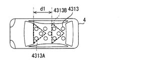
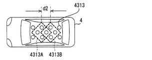
これら複数のアンテナ素子4313は、MIMO技術が適用されて、前側アンテナ4313Aと、後側アンテナ4313Bの2つのアンテナに動的に割り当てられる。つまり、前側アンテナ4313A、後側アンテナ4313Bは複数のアンテナ素子4313を備えるアンテナ素子群である。前側アンテナ4313Aは参照アンテナとして機能し、後側アンテナ4313Bは選択リソース用アンテナとして機能する。
The plurality of
図29に示すように、車載端末4300は、通信部4310、記憶部4320、制御部4330を備える。通信部4310は、複数のアンテナ素子4313の他に、送信部4311と受信部4312を備える。これら送信部4311、受信部4312は、複数のアンテナ素子4313を用いて送信、受信を行う。複数のアンテナ素子4313を用いる以外は、送信部4311、受信部4312は、第4実施形態の送信部1311、受信部1312と同じ機能を備える。
As shown in FIG. 29, the in-
制御部4330は、図30に示すように、機能として、特性情報決定部4331、通信制御部4332、受信状態信号送信部4333を備える。
As illustrated in FIG. 30, the
まず、特性情報決定部4331を説明する。第8実施形態でも、基地局4200は、周期的に参照信号Rを送信している。車載端末4300は、前側アンテナ4313Aと後側アンテナ4313Bで参照信号Rを受信する。なお、このときの前側アンテナ4313Aおよび後側アンテナ4313Bを構成するアンテナ素子4313は、予め車載端末4300の制御部4330が決定していてもよい。また、基地局4200が決定して、参照信号Rとともに、あるいは、その参照信号Rに先立って、車載端末4300に通知してもよい。
First, the characteristic
特性情報決定部4331は、各アンテナ素子4313が受信した参照信号Rを受信部4312から取得する。そして、前側アンテナ4313Aおよび後側アンテナ4313Bを構成する全部のアンテナ素子4313について、基地局4200が送信に用いる全部のアンテナ素子4213との間の伝搬路特性情報CCを決定する。それぞれの伝搬路特性情報CCの決定方法はこれまでの実施形態と同じでよい。
The characteristic
通信制御部4332は、複数のアンテナ素子4313から、前側アンテナ4313A、後側アンテナ4313Bとして用いるアンテナ素子413を決定して、前側アンテナ4313A、後側アンテナ4313Bを構成する。この前側アンテナ4313A、後側アンテナ4313Bで参照信号Rを受信する。後側アンテナ4313Bでも参照信号Rを送信するのは再現性指標を決定するためであり、再現性指標を決定しない場合には、後側アンテナ4313Bでは参照信号Rを受信しなくてもよい。
The
通信制御部4332は、前側アンテナ4313Aおよび後側アンテナ4313Bに割り当てるアンテナ素子4313を決定するために、車載端末4300の移動速度と基地局4200が信号を送信する送信周期を用いる。車載端末4300の移動速度に、基地局4200が信号を送信する送信周期を乗じることで、1送信周期の間に車載端末4300が移動する距離を算出する。
The
前側アンテナ4313Aおよび後側アンテナ4313Bにおいて互いに対応するアンテナ素子4313の間の距離(以下、アンテナ間距離)dが1送信周期の間に車載端末4300が移動する距離以上になるように、アンテナ素子4313の割り当てを決定する。
The
また、前側アンテナ4313Aおよび後側アンテナ4313Bを構成するアンテナ素子4313の配置形状が互いに同一になるように、前側アンテナ4313Aおよび後側アンテナ4313Bに割り当てるアンテナ素子4313を選択する。
In addition, the
この割り当てを、事前に基地局4200が決定して車載端末4300に通知してもよい。また、車載端末4300がこの割当を決定する場合には、基地局4200が信号を送信する送信周期は、基地局4200が送信周期を示す信号を送信し、この信号を車載端末4300が受信することで、車載端末4300が取得することができる。また、逐次、基地局4200が送信する信号を受信して測定してもよい。図31に、前側アンテナ4313Aと後側アンテナ4313Bの割り当ての一例を示している。また、図32に、前側アンテナ4313Aと後側アンテナ4313Bの割り当ての他の例を示している。図31の例も、図32の例も、前側アンテナ4313Aと後側アンテナ4313Bを構成するアンテナ素子4313の配置形状は互いに同一になっている。
This allocation may be determined in advance by the
また、図31の例では、アンテナ間距離dがd1になっており、図32の例では、アンテナ間距離dがd2になっている。d2はd1よりも短い。このように、アンテナ素子4313の割り当てを変更することで、アンテナ間距離dを変更することができる。
In the example of FIG. 31, the inter-antenna distance d is d1, and in the example of FIG. 32, the inter-antenna distance d is d2. d2 is shorter than d1. In this way, the antenna distance d can be changed by changing the assignment of the
受信状態信号送信部4333は、受信状態信号Srを、送信部4311から基地局4200に送信する。受信状態信号Srは、前側アンテナ4313Aおよび後側アンテナ4313Bを構成する全部のアンテナ素子4313とアンテナ素子4213の全部の組み合わせについての伝搬路特性情報CCと、参照信号Rを受信したときの車載端末4300の移動速度および現在位置と、アンテナ間距離dと、車載端末4300のIDとを含む信号である。
The reception state
図28(A)には、時刻t1において、基地局4200が参照信号Rを送信し、その後、受信状態信号Srを車載端末4300が送信している状態を示している。
FIG. 28 (A) shows a state where the
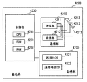
[基地局4200の構成]
図33に示すように、基地局4200は、図2のアンテナ213に代えて複数のアンテナ素子4213を備える。これ以外のハードウェア構成は、第1実施形態の基地局200と同じであり、基地局4200は、通信部4210、記憶部4220、制御部4230を備える。通信部4210は、送信部4211、受信部4212を備え、制御部4230は、CPU4240、ROM4250、RAM4260を備える。
[Configuration of Base Station 4200]
As shown in FIG. 33, the
記憶部4220は、再現性指標データベース4221と道路地図データベース4222を記憶する。再現性指標データベース4221は、後述する再現性決定部4235が決定した再現性指標を、地点に対応付けているデータベースである。
The
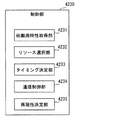
制御部4230は、図34に示すように、機能として、伝搬路特性取得部4231、リソース選択部4232、タイミング決定部4233、通信制御部4234、再現性決定部4235を備える。
As shown in FIG. 34, the
伝搬路特性取得部4231は、車載端末4300が送信し、受信部4212が受信した伝搬路特性情報CCを、受信部4212から取得する。取得した伝搬路特性情報CCのうち、前側アンテナ4313Aに対応する伝搬路特性情報CCを前側アンテナ伝搬路特性情報CCAとし、後側アンテナ4313Bに対応する伝搬路特性情報CCを後側アンテナ伝搬路特性情報CCBとする。また、取得時を、車載端末4300が受信位置(すなわち通信位置)に位置していたとする。つまり、前側アンテナ伝搬路特性情報CCAおよび後側アンテナ伝搬路特性情報CCBと通信位置とを対応付ける。
The propagation path
リソース選択部4232は、前側アンテナ4371Aが参照信号Rを受信した位置を通信位置とし、その通信位置において通信に用いるリソースを、伝搬路特性取得部4231が取得した前側アンテナ伝搬路特性情報CCAに基づいて決定する。リソース選択部4232は、この前側アンテナ伝搬路特性情報CCAに加えて、再現性指標データベース4221から受信時の位置に対応する再現性指標を取得し、この再現性指標も用いてリソースを選択する。
The
図35には、リソース選択部4232がリソースを選択するために用いる指標と、アンテナ素子4313の利用形態との関係を例示している。再現性指標は、再現性指標データベース4221から取得した、受信時の位置に対応する再現性指標である。
FIG. 35 exemplifies a relationship between an index used by the
推定SN比が基準以上のリソース量は、通信位置において予想される伝搬路特性情報CCから決定する。通信位置において予想される伝搬路特性情報CCは、第5実施形態と同様にして決定する。 The amount of resources whose estimated SN ratio is higher than the standard is determined from the propagation path characteristic information CC expected at the communication position. The propagation path characteristic information CC expected at the communication position is determined in the same manner as in the fifth embodiment.
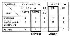
決定した伝搬路特性情報CCから、この推定SN比が基準以上のリソース量を決定する方法は、公知のMIMO技術において実行されている方法と同じでよい。例えば、伝搬路特性情報に基づき、公知の技術を用いてビームフォーミング、ダイバーシティコーディング、空間多重化(マルチストリーム)またはそれらを組み合わせて利用した際の各リソースにおけるSN比を推定し、これが基準以上となるリソースの量を決定する。ただし図35では簡単のため、ビームフォーミング、ダイバーシティコーディング、空間多重化のいずれかのみを利用する形態のみが記載されている。この「リソース量」におけるリソースは、これまでの実施形態と同じ意味である。ただし、本実施形態では、MIMO技術を用いるので、リソース選択部4232が決定するリソースにはMIMO技術により決定の自由度が発生する空間リソースも含まれ、空間リソースの決定はアンテナ素子の利用形態の選択により行われる。
The method for determining the resource amount with the estimated SN ratio equal to or greater than the reference from the determined propagation path characteristic information CC may be the same as the method executed in the known MIMO technology. For example, based on propagation path characteristic information, the SN ratio in each resource when using beamforming, diversity coding, spatial multiplexing (multi-stream) or a combination thereof using a known technique is estimated, Determine the amount of resources that will be. However, in FIG. 35, for the sake of simplicity, only a form using only one of beam forming, diversity coding, and spatial multiplexing is described. The resource in this “resource amount” has the same meaning as in the previous embodiments. However, in the present embodiment, since the MIMO technology is used, the resources determined by the
最大速度はさらに、各リソースにつき利用可能な変調速度、つまりリソースあたり伝送可能なデータ量を考慮し決定される。利用可能な変調速度は、推定SN比に基づき求められ、その方法は公知の適応変調技術において実行されている方法と同じでよい。図35では簡単のため、リソース量3に対し速度1として得られる値を示しており、基準以上のSN比と推定される全てのリソースを同じ変調速度で利用する場合に相当する。
The maximum rate is further determined in consideration of the modulation rate available for each resource, that is, the amount of data that can be transmitted per resource. The available modulation rate is determined based on the estimated signal-to-noise ratio, and the method may be the same as that performed in known adaptive modulation techniques. For the sake of simplicity, FIG. 35 shows a value obtained as the
リソース選択部4232は、図35に例示した指標と、次回の通信において重要とする指標とから、次回の通信におけるリソースを選択する。たとえば、通信の信頼性を重要指標とする場合、再現性が高く、かつ、推定SN比が基準以上のリソース量も多い利用形態であるシングルストリームの指向性2を、空間リソースを定めるアンテナの利用形態として選択する。また、通信速度を重要指標とする場合、最大速度が最も大きい、2本のストリームをアンテナ利用形態として選択する。なお、周波数と時間リソースの選択方法についてはこれまでの実施形態と同じである。
The
タイミング決定部4233は、受信部4212が受信した車載端末4300の移動速度に基づいて、後側アンテナ4313Bの位置が、前側アンテナ4313Aが参照信号Rを受信した位置となるタイミングである後側通信タイミングを決定する。
The
通信制御部4234は、参照信号Rを送信部4211から周期的に送信する。また、タイミング決定部4233が決定した後側通信タイミングで、リソース選択部4232が後側通信タイミングにおいて使用するリソースとして選択したリソースを用いて、任意の信号を車載端末4300に送信する。この任意の信号に加えて、第5実施形態と同様、参照信号Rを全サブチャネルを使用して送信する。この通信制御部4234は請求項の対象装置側通信制御部に相当する。
The
再現性決定部4235は、前側アンテナ伝搬路特性情報CCAと、後側通信タイミングにおいて基地局4200が送信した参照信号Rから決定した後側アンテナ伝搬路特性情報CCBとを比較して、伝搬路特性情報CCの再現性を表す再現性指標を決定する。再現性指標の決定方法は、第5実施形態の再現性決定部1235と同じでよい。さらに、再現性決定部4235は、決定した再現性指標を通信位置に対応付け、その再現性指標と通信位置とに基づいて、再現性指標データベース4221を更新する。更新された再現性指標データベース4221は、前述したように、リソースを選択する際に用いられる。
The
以上、本発明の実施形態を説明したが、本発明は上述の実施形態に限定されるものではなく、次の変形例も本発明の技術的範囲に含まれ、さらに、下記以外にも要旨を逸脱しない範囲内で種々変更して実施できる。 As mentioned above, although embodiment of this invention was described, this invention is not limited to the above-mentioned embodiment, The following modification is also contained in the technical scope of this invention, Furthermore, the summary other than the following is also included. Various modifications can be made without departing from the scope.
<変形例1>
図3には、伝搬路特性情報CCとして、周波数とSN比の関係を例示したが、周波数に代えてインパルス応答とSN比の関係を用いてもよい。
<
Although the relationship between the frequency and the SN ratio is illustrated as the propagation path characteristic information CC in FIG. 3, the relationship between the impulse response and the SN ratio may be used instead of the frequency.
<変形例2>
第8実施形態において、再現性指標データベース4221を備えず、車載端末4300が逐次送信する信号を比較して再現性指標を決定してもよい。この場合には、再現性指標は、厳密に同じ位置での再現性を表す指標ではない。しかし、第8実施形態では、利用形態を決定するために再現性指標を用いており、この場合には、厳密に同じ位置での再現性を表す指標でなくても、一応、利用形態を決定するために有用な情報となる。また、利用形態を決定するために、再現性指標を用いることは必須ではない。
<
In the eighth embodiment, the
<変形例3>
前述の実施形態では、移動体として自動車を示したが、他の移動体でもよい。他の移動体としては、鉄道車両、自転車、歩行者などがある。また、歩行者が移動通信装置を保持する場合、予め定めた複数の保持状態別に、電波伝搬マップ221を作成してもよい。保持状態は、たとえば、前面保持、ポケット収納などである。これらの保持状態を検出するためには、移動通信装置に、スマートフォンのようにカメラを備え、このカメラにより歩行者の顔が撮影できる状態を前面保持とすることが考えられる。この前面保持の位置を基準として、加速度センサにより移動通信装置の相対移動量を逐次検出すれば、移動通信装置がどの保持状態にあるかを検出できる。また、より単純に、移動通信装置に表示器を備え、歩行者に保持状態を指示するとともに、指示した保持状態になった場合にボタンを押してもらうようにしてもよい。
<
In the above-described embodiment, an automobile is shown as a moving body, but another moving body may be used. Examples of other moving bodies include railway vehicles, bicycles, and pedestrians. When a pedestrian holds a mobile communication device, the radio
<変形例4>
前述の実施形態では、伝搬路特性情報CCを決定するために参照信号Rを送信していた。しかし、伝搬路特性情報CCを決定するために参照信号Rを送信することは必須ではない。参照信号Rは、受信側において既知の信号である。しかし、受信側が受信状態を送信側に返送すれば、送信側は送信した信号が既知であるので、返送された受信状態と、送信した信号から、伝搬路特性情報CCを送信側において決定することができる。この場合、伝搬路特性情報CCを決定するための信号は任意の信号でよい。したがって、このようにすれば、参照信号Rを付加することによるオーバーヘッドが生じない利点がある。
<
In the above-described embodiment, the reference signal R is transmitted to determine the propagation path characteristic information CC. However, it is not essential to transmit the reference signal R in order to determine the propagation path characteristic information CC. The reference signal R is a signal known on the receiving side. However, if the reception side returns the reception state to the transmission side, the transmission side knows the transmitted signal, and therefore the propagation path characteristic information CC is determined on the transmission side from the returned reception state and the transmitted signal. Can do. In this case, the signal for determining the propagation path characteristic information CC may be an arbitrary signal. Therefore, if this is done, there is an advantage that no overhead is caused by adding the reference signal R.
<変形例5>
電波伝搬マップ221を、基地局200と通信可能なサーバが記憶していてもよい。
<
The radio
<変形例6>
第1実施形態では、車載端末300の型式をアンテナ決定情報としており、伝搬路特性取得部234は、伝搬路特性情報CCを取得する電波伝搬マップ221を、位置予測情報に含まれている車載端末300の型式と同じ電波伝搬マップ221としていた。型式が同じであればアンテナ特性が同じだからである。しかし、車載端末300の型式以外によりアンテナ特性が共通であるかを判断してもよい。どの程度のアンテナ特性の違いまでを共通の範囲とするかは、要求性能に基づいて決定することになる。
<
In the first embodiment, the type of the in-
変形例6では、車載端末300の型式とは別のアンテナ決定情報を用いる。具体的には、変形例6では、アンテナ決定情報は、車両4の車種名である。車種名は、車名と称されることもある。車載端末300が車両4の工場出荷時に取り付けられていれば、車両4の車種名が定まると車載端末300の型式が特定できるので、車両4の車種名をアンテナ決定情報として用いることができるのである。なお、車両4の車種名は、車両4を分類しているので、車両分類の一例に相当する。
In the sixth modification, antenna determination information different from the model of the in-
変形例6では、車載端末の300が備える特性決定情報アップロード部335および位置予測情報アップロード部336は、車載端末300の型式に代えて、車両4の車種名をアップロードする。車両4の車種名をアップロードするために、車載端末300の記憶部320には、車両4の車種名が予め記憶されている。
In the modified example 6, the characteristic determination information upload
基地局200が備える電波伝搬マップ221は、伝搬路特性情報CCが、車両4の車種名別に作成されており、マップ更新部231は、車両4の車種名に基づいて更新する電波伝搬マップ221を特定する。また、伝搬路特性取得部234は、伝搬路特性情報CCを取得する電波伝搬マップ221を、位置予測情報に含まれている車両4の車種名と同じ電波伝搬マップ221とする。
In the radio
<変形例7>
変形例7では、アンテナ決定情報として車種分類を用いる。車種分類は、アンテナ特性の類似性に基づいて車両の種類を分類したものである。変形例6で示した車両4の車種名をアンテナ決定情報とする場合、車両4の車種名が同一であればアンテナ特性が同一であると考えることができる。したがって、選択リソース用アンテナとアンテナ特性が同一の伝搬路特性情報CCに基づいてリソースを選択することができる利点がある。しかし、電波伝搬マップ221を車両4の車種名別に持つ必要がある。
<
In the modified example 7, vehicle type classification is used as the antenna determination information. The vehicle type classification classifies the type of vehicle based on the similarity of antenna characteristics. When the vehicle type name of the
車種分類は、車両4の車種名よりも、電波伝搬マップ221の汎用性を高めるための分類であり、アンテナ特性が共通する範囲で、一つの分類としている。したがって、車種分類は、変形例6で示した車両4の車種名よりも広い概念である。ただし、車両を大きく分けたときに、自動車および鉄道車両などの概念がある。これらは、車両が走行する社会的基盤設備による分類である。しかし、ここでの車種分類は、自動車および鉄道車両よりは狭い概念である。具体的には、車種分類は、たとえば、自動車をさらに分類した概念である乗用車、バスや、鉄道車両をさらに分類した概念である新幹線が、具体的な車種分類である。この車種分類は、車両の全高により区分した分類とすることもできる。なお、車種分類も、車両を分類しているので、車両分類の一例に相当する。
The vehicle type classification is a classification for enhancing the versatility of the radio
変形例7では、車載端末の300が備える特性決定情報アップロード部335および位置予測情報アップロード部336は、車載端末300の型式に代えて、車種分類をアップロードする。車種分類をアップロードするために、車載端末300の記憶部320には、車種分類が予め記憶されている。
In the modified example 7, the characteristic determination information upload
基地局200が備える電波伝搬マップ221は、伝搬路特性情報CCが、車種分類別に作成されており、マップ更新部231は、車種分類に基づいて更新する電波伝搬マップ221を特定する。また、伝搬路特性取得部234は、伝搬路特性情報CCを取得する電波伝搬マップ221を、位置予測情報に含まれている車種分類と同じ電波伝搬マップ221とする。
In the radio
<変形例8>
変形例8では、アンテナ決定情報としてアンテナの設置高さを用いる。伝搬路特性は三次元位置に対して変動する。そのため、アンテナの設置高さもアンテナ特性となるのである。
<Modification 8>
In the modification 8, the antenna installation height is used as the antenna determination information. The propagation path characteristics vary with respect to the three-dimensional position. Therefore, the installation height of the antenna is also an antenna characteristic.
変形例8では、車載端末の300が備える特性決定情報アップロード部335および位置予測情報アップロード部336は、車載端末300の型式に代えて、アンテナ313の設置高さ、すなわち、選択リソース用アンテナの設置高さが含まれたアンテナ決定情報をアップロードする。アンテナ313の設置高さは、記憶部320に予め記憶されている。アップロードするアンテナ決定情報には、選択リソース用アンテナの設置高さの他に、アンテナ形式が含まれ、また、アンテナの姿勢を含ませてもよい。
In the modified example 8, the characteristic determination information upload
基地局200が備える電波伝搬マップ221は、伝搬路特性情報CCが、上記アンテナ決定情報に基づいて区別された参照アンテナ別に作成されている。つまり、電波伝搬マップ221は、伝搬路特性情報CCが、参照アンテナの設置高さ別に作成されており、アンテナ形式など、他のアンテナ決定情報によっても区別されて作成されている。
In the radio
マップ更新部231は、設置高さなどのアンテナ特性が、アンテナ313と同じ参照アンテナに対する電波伝搬マップ221を、特性決定情報アップロード部335がアンテナ決定情報とともにアップロードした参照信号Rの受信時位置と伝搬路特性情報CCに基づいて更新する。
The
また、伝搬路特性取得部234は、伝搬路特性情報CCを取得する電波伝搬マップ221を、位置予測情報に含まれているアンテナの設置高さ以外のアンテナ決定情報から定まる電波伝搬マップ221であって、設置高さ条件を満たす電波伝搬マップ221とする。
In addition, the propagation path
設置高さ条件は、位置予測情報に含まれているアンテナ313の設置高さと参照アンテナの設置高さの差または比が、一定範囲内であるという条件である。この条件を満たす参照アンテナが複数ある場合には、アンテナ313の設置高さに最も近い設置高さの参照アンテナに対応する電波伝搬マップ221を、伝搬路特性情報CCを取得する電波伝搬マップ221とする。
The installation height condition is a condition that the difference or ratio between the installation height of the
この変形例8では、車種が異なっていても、アンテナ設置高さなどのアンテナ特性が共通すれば、異なる車種間で、電波伝搬マップ221を共有することができる。たとえば、全高が低めのステーションワゴン車と全高が高めのセダン型の車は、車種が異なるが、アンテナ設置高さが上記設置高さ条件を満たす可能性がある。また、この変形例8では、一部のオフロード車のように、車高調整機能を有する車に対しては、同じ車種でも、異なるアンテナ設置高さの電波伝搬マップ221を適用することもできる。
In the modified example 8, even if the vehicle types are different, the radio
<変形例9>
変形例9では、アンテナ決定情報として、アンテナ313の保持状態を用いる。保持状態は、具体的には、アンテナが固定されているか、固定されていないかの何れかである。固定されていない状態は、移動通信装置が携帯型端末であり、その携帯型端末が移動体に固定された保持具に保持されていない状態である。移動体に固定された保持具に保持されているかどうかは、携帯型端末に備えられている加速度センサが検出する加速度に基づいて判断する。移動体に固定された保持具に保持されずに移動する場合、保持具に保持されている場合と比較して、加速度センサが検出する加速度の時間変化が複雑になる。よって、加速度の時間変化から、携帯型端末が保持具に保持されているか否かを判断する。また、移動体に固定された保持具に保持されていない場合、位置の時間変化も、保持具に保持されている場合に比較して複雑になる。よって、位置の時間変化から、携帯型端末が保持具に保持されているか否かを判断してもよい。
<
In the
変形例9では、移動通信装置の特性決定情報アップロード部335および位置予測情報アップロード部336は、移動通信装置が固定されているか否かを表す情報を、車載端末300の形式に代えて、アンテナ決定情報としてアップロードする。移動通信装置の記憶部320には、移動通信装置が固定型であるか移動型であるかが記憶されている。移動通信装置が固定型であれば、移動通信装置は固定されているとする。一方、移動通信装置が携帯型端末であれば、加速度あるいは位置の時間変化から、移動体に固定された保持具に保持されているか否かを判断する。
In the modified example 9, the characteristic determination information upload
さらに、固定型の移動通信装置は、固定部位も保持状態としてアップロードする。固定部位も記憶部320に記憶されている。固定部位は、アンテナ特性に違いが生じるか否かに基づいて部位が区別されている。たとえば、固定部位の記憶例は、屋根の上、ミラー、窓、トランクグリッドなどである。
Further, the fixed type mobile communication device uploads the fixed part as the holding state. The fixed part is also stored in the
一方、携帯型の移動通信装置であれば、移動通信装置が複数の座席を備える移動体で用いられているか否かを判断する。移動通信装置が複数の座席を備える移動体で用いられていると判断できる場合には、どの座席上に存在しているかも判断する。 On the other hand, in the case of a portable mobile communication device, it is determined whether or not the mobile communication device is used in a mobile body having a plurality of seats. If it can be determined that the mobile communication device is used in a mobile object having a plurality of seats, it is also determined which seat is present.
そして、動通信装置が複数の座席を備える移動体で用いられているか否か、および、どの座席上に存在しているかを表す情報も保持状態としてアップロードする。移動通信装置が複数の座席を備える移動体で用いられているか否か、および、どの座席上に存在しているかは、移動通信装置を所持しているユーザへの問い合わせに基づいて決定する。 Then, information indicating whether or not the mobile communication device is used in a mobile body having a plurality of seats and on which seat is uploaded as a holding state. Whether or not the mobile communication device is used in a mobile body having a plurality of seats and on which seat is determined based on an inquiry to the user who owns the mobile communication device.
基地局200が備える電波伝搬マップ221は、伝搬路特性情報CCが、移動通信装置が固定型であるか携帯型であるかが区別されて作成されており、かつ、固定型の移動通信装置については、上述した固定部位別に作成されている。一方、携帯型の移動通信装置については、複数の座席を備える移動体で用いられている場合とそれ以外で区別されて電波伝搬マップ221が作成され、かつ、複数の座席を備える移動体で用いられている場合の電波伝搬マップ221については、存在している座席別に作成されている。
The radio
マップ更新部231は、更新する電波伝搬マップ221を、アンテナ決定情報保持状態が同じ電波伝搬マップ221とする。また、伝搬路特性取得部234は、伝搬路特性情報CCを取得する電波伝搬マップ221を、アンテナ決定情報と保持状態が同じ電波伝搬マップ221とする。
The
<変形例10>
変形例8において、アンテナの設置高さに加えて、さらに、アンテナ種別を、アンテナ決定情報として用いてもよい。また、変形例9において、保持状態に加えて、アンテナ種別をアンテナ決定情報として用いてもよい。
<Modification 10>
In Modification 8, in addition to the antenna installation height, the antenna type may be used as antenna determination information. In
1:移動通信システム 4:車両 5:道路 6:車両 41:速度センサ 42:位置検出器 100:移動通信システム 200:基地局 210:通信部 211:送信部
212:受信部 213:アンテナ 220:記憶部 221:電波伝搬マップ 222:信頼性指標データベース 223:道路地図データベース 230:制御部 231:マップ更新部 232:位置予測情報取得部 233:位置予測部 234:伝搬路特性取得部 235:リソース選択部 236:通信制御部 237:信頼性更新部 238:距離決定部 239:特性変化決定部 240:特性変化補償部 300:車載端末 310:通信部 311:送信部 312:受信部 313:アンテナ 320:記憶部 330:制御部 331:位置決定部 332:通信制御部 333:受信制御部 334:送信制御部 335:特性決定情報アップロード部 336:位置予測情報アップロード部 337:誤りリソースアップロード部 338:誤り検出部 339:特性情報決定部 340:差分決定部 413:アンテナ素子
1: mobile communication system 4: vehicle 5: road 6: vehicle 41: speed sensor 42: position detector 100: mobile communication system 200: base station 210: communication unit 211: transmission unit 212: reception unit 213: antenna 220: storage Unit 221: radio wave propagation map 222: reliability index database 223: road map database 230: control unit 231: map update unit 232: position prediction information acquisition unit 233: position prediction unit 234: propagation path characteristic acquisition unit 235: resource selection unit 236: Communication control unit 237: Reliability update unit 238: Distance determination unit 239: Characteristic change determination unit 240: Characteristic change compensation unit 300: In-vehicle terminal 310: Communication unit 311: Transmission unit 312: Reception unit 313: Antenna 320: Storage Unit 330: Control unit 331: Position determination unit 332: Communication control unit 333: Reception control Part 334: transmission control section 335: Characterization uploading unit 336: position prediction uploading unit 337: error resource uploader 338: error detection unit 339: the characteristic data setting section 340: difference determining section 413: antenna element
Claims (25)
アンテナ形式を少なくとも含むアンテナ特性が前記選択リソース用アンテナと共通する参照アンテナと前記対象通信装置との間の伝搬路特性に関する情報である伝搬路特性情報を、将来の通信位置に対応付けて取得する伝搬路特性取得部(234、1231、2232、3232、3332、4231)と、
前記伝搬路特性取得部が取得した前記伝搬路特性情報に基づいて、前記通信位置において前記移動通信装置と前記対象通信装置との通信に用いるリソースを、前記移動通信装置の前記選択リソース用アンテナが前記通信位置に位置する前に選択するリソース選択部(235、1232、2233、3234、3334、4232)とを備える移動通信システム。 A mobile communication device that is used in a mobile body and includes a selection resource antenna (313, 1372, 2372, 3273, 3373, 4313B) for performing communication using a selected resource, and performs wireless communication using the selection resource antenna (300, 1300, 2300, 3300, 4300) and a mobile communication system (100, 1000, 300, 4200) including a target communication device (200, 1200, 2200, 3200, 3300, 4200) that is a communication target of the mobile communication device. 2000, 3000, 4000)
Propagation path characteristic information, which is information related to propagation path characteristics between the reference antenna having the antenna characteristics including at least the antenna format, in common with the antenna for the selected resource, and the target communication apparatus is acquired in association with a future communication position. Propagation path characteristic acquisition unit (234, 1231, 2232, 3232, 3332, 4231);
Based on the propagation path characteristic information acquired by the propagation path characteristic acquisition unit, a resource used for communication between the mobile communication apparatus and the target communication apparatus at the communication position is selected by the selected resource antenna of the mobile communication apparatus. A mobile communication system comprising resource selection units (235, 1232, 2233, 3234, 3334, 4232) to be selected before being located at the communication position.
前記移動通信装置の前記選択リソース用アンテナの位置を予測するための位置予測情報を取得する位置予測情報取得部(232)と、
前記位置予測情報に基づいて、前記選択リソース用アンテナの予測位置を逐次決定する位置予測部(233)とを備え、
前記伝搬路特性取得部は、前記伝搬路特性情報を前記通信位置に対応づけて格納したデータベースである電波伝搬マップ(221)から、前記予測位置における前記伝搬路特性情報を取得し、
前記リソース選択部(235)は、前記予測位置を前記通信位置とし、前記予測位置において前記移動通信装置と前記対象通信装置との通信に用いるリソースを選択する移動通信システム。 In claim 1,
A position prediction information acquisition unit (232) that acquires position prediction information for predicting the position of the antenna for the selected resource of the mobile communication device;
A position prediction unit (233) for sequentially determining the predicted position of the antenna for the selected resource based on the position prediction information;
The propagation path characteristic acquisition unit acquires the propagation path characteristic information at the predicted position from a radio wave propagation map (221) which is a database storing the propagation path characteristic information in association with the communication position.
The resource selection unit (235) is a mobile communication system that uses the predicted position as the communication position, and selects a resource used for communication between the mobile communication device and the target communication device at the predicted position.
前記対象通信装置は基地局(200)であり、
前記基地局が、前記位置予測情報取得部、前記位置予測部、前記伝搬路特性取得部(234)、前記リソース選択部、前記電波伝搬マップを記憶した記憶部(220)を備え、
前記電波伝搬マップは、前記伝搬路特性情報を複数種類の前記参照アンテナについて格納しており、
前記移動通信装置(300)は、アップロード時点以後の前記位置予測情報を、前記アンテナ特性を決定できる情報であるアンテナ決定情報とともに、前記基地局にアップロードする位置予測情報アップロード部(336)を備え、
前記伝搬路特性取得部は、前記位置予測部が予測した前記予測位置を前記通信位置とし、且つ、前記移動通信装置からアップロードされた前記アンテナ決定情報に基づいて前記参照アンテナを決定し、決定した前記通信位置および前記参照アンテナにより定まる前記伝搬路特性情報を前記電波伝搬マップから取得する移動通信システム。 In claim 2,
The target communication device is a base station (200),
The base station includes the position prediction information acquisition unit, the position prediction unit, the propagation path characteristic acquisition unit (234), the resource selection unit, and a storage unit (220) that stores the radio wave propagation map,
The radio wave propagation map stores the propagation path characteristic information for a plurality of types of the reference antennas,
The mobile communication device (300) includes a position prediction information upload unit (336) that uploads the position prediction information after the upload time point to the base station together with antenna determination information that is information that can determine the antenna characteristics.
The propagation path characteristic acquisition unit determines the reference antenna based on the antenna determination information uploaded from the mobile communication device, using the predicted position predicted by the position prediction unit as the communication position A mobile communication system that acquires the propagation path characteristic information determined by the communication position and the reference antenna from the radio wave propagation map.
前記移動体は車両であり、
前記位置予測情報アップロード部は、前記アンテナ決定情報として、前記移動通信装置が前記車両で用いられた場合の前記アンテナ特性に基づいて前記車両を分類した車両分類をアップロードし、
前記伝搬路特性取得部は、前記車両分類に基づいて前記参照アンテナを決定する移動通信システム。 In claim 3,
The moving body is a vehicle;
The position prediction information upload unit uploads a vehicle classification obtained by classifying the vehicle based on the antenna characteristics when the mobile communication device is used in the vehicle as the antenna determination information,
The propagation path characteristic acquisition unit is a mobile communication system that determines the reference antenna based on the vehicle classification.
前記位置予測情報アップロード部は、前記車両分類として前記車両の車種名をアップロードし、
前記伝搬路特性取得部は、前記車両の車種名に基づいて前記参照アンテナを決定する移動通信システム。 In claim 4,
The position prediction information upload unit uploads a model name of the vehicle as the vehicle classification,
The propagation path characteristic acquisition unit is a mobile communication system that determines the reference antenna based on a model name of the vehicle.
前記位置予測情報アップロード部は、前記車両分類として、前記アンテナ特性の類似性に基づいて前記車両の種類を分類した車種分類をアップロードし、
前記伝搬路特性取得部は、前記車種分類に基づいて前記参照アンテナを決定する移動通信システム。 In claim 4,
The position prediction information upload unit uploads a vehicle type classification obtained by classifying the vehicle type based on the similarity of the antenna characteristics as the vehicle classification,
The propagation path characteristic acquisition unit is a mobile communication system that determines the reference antenna based on the vehicle type classification.
前記移動体は車両であり、
前記位置予測情報アップロード部は、前記アンテナ決定情報として、前記移動通信装置が前記車両で用いられた場合の前記選択リソース用アンテナの設置高さをアップロードし、
前記伝搬路特性取得部は、前記選択リソース用アンテナの設置高さと、前記参照アンテナの設置高さとに基づいて前記参照アンテナを決定する移動通信システム。 In claim 3,
The moving body is a vehicle;
The position prediction information upload unit uploads the installation height of the antenna for the selected resource when the mobile communication device is used in the vehicle as the antenna determination information,
The propagation path characteristic acquisition unit is a mobile communication system that determines the reference antenna based on an installation height of the selected resource antenna and an installation height of the reference antenna.
前記位置予測情報アップロード部は、前記アンテナ決定情報として、前記選択リソース用アンテナの保持状態をアップロードし、
前記伝搬路特性取得部は、前記選択リソース用アンテナの保持状態と前記参照アンテナの保持状態が同じか否かに基づいて、前記参照アンテナを決定する移動通信システム。 In claim 3,
The position prediction information upload unit uploads the holding state of the antenna for the selected resource as the antenna determination information,
The propagation path characteristic acquisition unit is a mobile communication system that determines the reference antenna based on whether the holding state of the selected resource antenna and the holding state of the reference antenna are the same.
前記伝搬路特性取得部は、前記選択リソース用アンテナの保持状態と前記参照アンテナの保持状態が同じか否かを、前記選択リソース用アンテナおよび前記参照アンテナがともに固定されているか否かに基づいて決定する移動通信システム。 In claim 8,
The propagation path characteristic acquisition unit determines whether the holding state of the selection resource antenna and the holding state of the reference antenna are the same based on whether both the selection resource antenna and the reference antenna are fixed. Mobile communication system to be determined.
前記伝搬路特性取得部は、アンテナが固定されているか否かに加え、前記選択リソース用アンテナと前記参照アンテナがともに固定されている場合に、前記選択リソース用アンテナと前記参照アンテナの固定部位が同じか否かも含めて、前記選択リソース用アンテナの保持状態と前記参照アンテナの保持状態が同じか否かを決定する移動通信システム。 In claim 9,
In addition to whether or not the antenna is fixed, the propagation path characteristic acquisition unit determines whether the selected resource antenna and the reference antenna are fixed when the selected resource antenna and the reference antenna are both fixed. A mobile communication system that determines whether the holding state of the selected resource antenna and the holding state of the reference antenna are the same, including whether or not they are the same.
前記伝搬路特性取得部は、アンテナが固定されているか否かに加え、前記選択リソース用アンテナと前記参照アンテナがともに固定されていない場合に、前記選択リソース用アンテナと前記参照アンテナが、同じ座席上にあるか否かも含めて、前記選択リソース用アンテナの保持状態と前記参照アンテナの保持状態が同じか否かを決定する移動通信システム。 In any one of Claims 8-10,
In addition to whether the antenna is fixed, the propagation path characteristic acquisition unit, when both the antenna for selection resource and the reference antenna are not fixed, the antenna for selection resource and the reference antenna are the same seat A mobile communication system that determines whether the holding state of the selected resource antenna and the holding state of the reference antenna are the same, including whether or not they are above.
前記移動通信装置は、
前記参照アンテナ(313)と、
現在位置を逐次決定する位置決定部(331)と、
前記伝搬路特性情報および前記伝搬路特性情報を決定できる情報のいずれかである特性決定情報を、前記位置決定部が決定した最新の現在位置であるアップロード時位置とともに前記基地局にアップロードする特性決定情報アップロード部(335)とを備え、
前記基地局は、前記移動通信装置がアップロードした前記特性決定情報と前記アップロード時位置に基づいて、前記電波伝搬マップを更新するマップ更新部(231)を備える移動通信システム。 In any one of Claims 3-11,
The mobile communication device
The reference antenna (313);
A position determining unit (331) for sequentially determining the current position;
Characteristic determination for uploading to the base station the characteristic determination information that is one of the propagation path characteristic information and the information that can determine the propagation path characteristic information together with the uploading position that is the latest current position determined by the position determination unit. An information upload unit (335),
The base station is a mobile communication system including a map update unit (231) that updates the radio wave propagation map based on the characteristic determination information uploaded by the mobile communication device and the upload position.
前記電波伝搬マップは、前記電波伝搬マップに含まれている前記伝搬路特性情報に対する信頼性を表す信頼性指標も備えており、
前記リソース選択部は、前記伝搬路特性情報に加えて、前記伝搬路特性に対応する前記信頼性指標も用いて、前記リソースを選択する移動通信システム。 In claim 12,
The radio wave propagation map also includes a reliability index that represents the reliability of the propagation path characteristic information included in the radio wave propagation map,
The resource selection unit is a mobile communication system that selects the resource using the reliability index corresponding to the propagation path characteristic in addition to the propagation path characteristic information.
前記信頼性指標が、前記通信位置が同じである複数の前記伝搬路特性情報に基づいて定まる、前記伝搬路特性情報の再現性を表す再現性指標である移動通信システム。 In claim 13,
The mobile communication system, wherein the reliability index is a reproducibility index representing reproducibility of the propagation path characteristic information, which is determined based on a plurality of the propagation path characteristic information having the same communication position.
前記移動通信装置は、
前記基地局が送信した信号を受信した場合に、受信した信号に発生している誤りを検出する誤り検出部(337)と、
前記誤り検出部が誤りを検出した信号の伝送に用いられた前記リソースを表す誤りリソース情報を前記基地局にアップロードする誤りリソースアップロード部(336)とを備え、
前記基地局は、
前記信頼性指標を、前記誤りリソース情報に基づいて更新する信頼性更新部(237)を備える移動通信システム。 In claim 13 or 14,
The mobile communication device
An error detection unit (337) that detects an error occurring in the received signal when the signal transmitted by the base station is received;
An error resource upload unit (336) for uploading error resource information representing the resource used for transmission of a signal in which the error detection unit has detected an error to the base station;
The base station
A mobile communication system provided with the reliability update part (237) which updates the said reliability parameter | index based on the said error resource information.
前記移動通信装置は、
外部からダウンロードした前記電波伝搬マップを記憶するダウンロードデータ記憶部(320)と、
前記基地局が送信した信号を前記参照アンテナで受信した場合に、前記伝搬路特性情報を決定する特性情報決定部(339)と、
前記特性情報決定部が決定した前記伝搬路特性情報と、前記ダウンロードデータ記憶部に記憶されている前記電波伝搬マップにおいて前記特性情報決定部が決定した前記伝搬路特性情報に対応する部分との差分である伝搬路特性差分を決定する差分決定部(340)とを備え、
前記特性決定情報アップロード部は、前記伝搬路特性差分を前記特性決定情報としてアップロードし、
前記基地局の前記マップ更新部は、前記伝搬路特性差分に基づいて前記電波伝搬マップを更新する移動通信システム。 In any one of Claims 12-15,
The mobile communication device
A download data storage unit (320) for storing the radio wave propagation map downloaded from the outside;
A characteristic information determining unit (339) for determining the propagation path characteristic information when a signal transmitted by the base station is received by the reference antenna;
The difference between the propagation path characteristic information determined by the characteristic information determination section and the portion corresponding to the propagation path characteristic information determined by the characteristic information determination section in the radio wave propagation map stored in the download data storage section A difference determining unit (340) for determining a propagation path characteristic difference that is
The characteristic determination information upload unit uploads the propagation path characteristic difference as the characteristic determination information,
The mobile communication system, wherein the map update unit of the base station updates the radio wave propagation map based on the propagation path characteristic difference.
前記移動通信装置の移動速度を取得し、取得した前記移動速度と通信時間から、通信期間中の移動距離を決定する距離決定部(238)と、
前記距離決定部が決定した移動距離と、前記電波伝搬マップとに基づいて、前記通信期間における前記伝搬路特性情報の変化を決定する特性変化決定部(239)と、
前記特性変化決定部が決定した、前記通信期間における前記伝搬路特性情報の変化が通信に与える影響を軽減させる補償を通信信号に対して行う特性変化補償部(240)とを備える移動通信システム。 In any one of Claims 11-16,
A distance determining unit (238) for acquiring a moving speed of the mobile communication device, and determining a moving distance during a communication period from the acquired moving speed and communication time;
A characteristic change determining unit (239) for determining a change in the propagation path characteristic information in the communication period based on the moving distance determined by the distance determining unit and the radio wave propagation map;
A mobile communication system comprising: a characteristic change compensator (240) that performs compensation for a communication signal, which is determined by the characteristic change determiner, to reduce an influence on communication by a change in the propagation path characteristic information in the communication period.
前記対象通信装置(1200)は、伝搬路推定用信号を逐次送信し、
前記移動通信装置(1300)は、前記移動体の移動方向に互いに前後関係になり、互いに同形式のアンテナである前側アンテナ(1371)および後側アンテナ(1372)を備え、前記前側アンテナを前記参照アンテナとし、前記後側アンテナを前記選択リソース用アンテナとし、
さらに、前記移動通信装置は、
前記対象通信装置が送信した前記伝搬路推定用信号を前記前側アンテナで受信した場合の前記伝搬路特性情報である前側アンテナ伝搬路特性情報を決定する特性情報決定部(1331)と、
前記前側アンテナで前記伝搬路推定用信号を受信したときの前記移動通信装置の移動速度と前記前側アンテナ伝搬路特性情報とを前記対象通信装置に送信する受信情報送信部(1332)とを備え、
前記対象通信装置は、前記伝搬路特性取得部(1231)と前記リソース選択部(1232)とを備え、
前記伝搬路特性取得部は、前記移動通信装置が送信した前記前側アンテナ伝搬路特性情報を前記対象通信装置が備える受信部が受信した位置に対応付けて取得し、
前記リソース選択部は、前記前側アンテナが前記伝搬路推定用信号を受信した位置を前記通信位置として、前記通信位置において通信に用いるリソースを選択し、
さらに、前記対象通信装置は、
前記移動通信装置が送信した前記移動速度に基づいて、前記後側アンテナの位置が、前記前側アンテナによる前記伝搬路推定用信号の通信が行われた位置となるタイミングである後側通信タイミングを決定するタイミング決定部(1233)と、
前記タイミング決定部が決定した前記後側通信タイミングにおいて、前記リソース選択部が選択したリソースで前記移動通信装置と通信する通信制御部(1234)を備える移動通信システム。 In claim 1,
The target communication device (1200) sequentially transmits a propagation path estimation signal,
The mobile communication device (1300) includes a front antenna (1371) and a rear antenna (1372) that are in the same relationship with each other in the moving direction of the mobile body and are the same type of antenna, and the front antenna is referred to An antenna, the rear antenna as the selected resource antenna,
Furthermore, the mobile communication device comprises:
A characteristic information determination unit (1331) that determines the front antenna propagation path characteristic information that is the propagation path characteristic information when the propagation path estimation signal transmitted by the target communication device is received by the front antenna;
A reception information transmission unit (1332) that transmits to the target communication device the moving speed of the mobile communication device when the propagation path estimation signal is received by the front antenna and the front antenna propagation channel characteristic information;
The target communication device includes the propagation path characteristic acquisition unit (1231) and the resource selection unit (1232),
The propagation path characteristic acquisition unit acquires the front antenna propagation path characteristic information transmitted by the mobile communication device in association with a position received by a reception unit included in the target communication device,
The resource selection unit selects a resource used for communication at the communication position, with the position at which the front antenna receives the propagation path estimation signal as the communication position,
Furthermore, the target communication device is
Based on the moving speed transmitted by the mobile communication device, the rear communication timing is determined such that the position of the rear antenna is a position at which the communication of the propagation path estimation signal is performed by the front antenna. A timing determination unit (1233) for
A mobile communication system comprising a communication control unit (1234) that communicates with the mobile communication device using the resource selected by the resource selection unit at the rear communication timing determined by the timing determination unit.
前記タイミング決定部が前記後側通信タイミングを決定するために用いた前記伝搬路推定用信号を前記対象通信装置が送信したタイミングを前側通信タイミングとし、
前記通信制御部は、前記後側通信タイミングで前記伝搬路推定用信号を送信し、
前記特性情報決定部は、前記前側アンテナ伝搬路特性情報に加えて、前記後側通信タイミングで前記対象通信装置が送信した前記伝搬路推定用信号を前記後側アンテナで受信した場合の前記伝搬路特性情報である後側アンテナ伝搬路特性情報を決定し、
前記受信情報送信部は、前記前側通信タイミングで前記伝搬路推定用信号を受信したときの前記移動通信装置の移動速度と前記前側アンテナ伝搬路特性情報に加えて、前記前側通信タイミングで前記伝搬路推定用信号を受信したときの現在位置も送信し、かつ、前記後側アンテナ伝搬路特性情報も前記対象通信装置に送信し、
前記対象通信装置は、
前記伝搬路特性情報の再現性を表す再現性指標を、地点に対応付けているデータベースである再現性指標データベース(1224)と、
前記前側アンテナ伝搬路特性情報と前記後側アンテナ伝搬路特性情報との比較に基づいて、前記前側アンテナ伝搬路特性情報に対応する地点に対する前記再現性指標を決定し、決定した前記再現性指標に基づいて前記再現性指標データベースを更新する再現性決定部
(1235)とを備え、
前記通信制御部は、前記前側アンテナ伝搬路特性情報とともに受信した現在位置と前記再現性指標データベースに基づいて、前記後側通信タイミングで前記伝搬路推定用信号を送信する際の通信の信頼性に関するパラメータ設定を決定する移動通信システム。 In claim 18,
The timing at which the target communication device has transmitted the propagation path estimation signal used by the timing determination unit to determine the rear communication timing is defined as a front communication timing,
The communication control unit transmits the propagation path estimation signal at the rear communication timing,
In addition to the front antenna propagation path characteristic information, the characteristic information determination unit receives the propagation path estimation signal transmitted by the target communication apparatus at the rear communication timing by the rear antenna. Determine the rear antenna propagation path characteristic information that is characteristic information,
In addition to the moving speed of the mobile communication apparatus and the front antenna propagation path characteristic information when the propagation path estimation signal is received at the front communication timing, the reception information transmitting unit transmits the propagation path at the front communication timing. Also transmits the current position when the estimation signal is received, and also transmits the rear antenna propagation path characteristic information to the target communication device,
The target communication device is
A reproducibility index database (1224) which is a database in which a reproducibility index representing the reproducibility of the propagation path characteristic information is associated with a point;
Based on the comparison between the front antenna propagation path characteristic information and the rear antenna propagation path characteristic information, the reproducibility index for the point corresponding to the front antenna propagation path characteristic information is determined, and the determined reproducibility index A reproducibility determination unit (1235) for updating the reproducibility index database based on
The communication control unit relates to reliability of communication when transmitting the propagation path estimation signal at the rear communication timing based on the current position received together with the front antenna propagation path characteristic information and the reproducibility index database. A mobile communication system for determining parameter settings.
前記対象通信装置(2200、3200)は、前記移動通信装置(2300、3300)が用いられている前記移動体とは異なる移動体に搭載されており、
前記対象通信装置が用いられている前記移動体を第1移動体(6)とし、前記移動通信装置が用いられている前記移動体を第2移動体(4)とし、
前記移動通信装置は、前記移動体の移動方向に互いに前後関係になり、互いに同形式のアンテナである前側アンテナ(2371、3372)および後側アンテナ(2372、3373)を備え、前記前側アンテナを前記参照アンテナとし、前記後側アンテナを前記選択リソース用アンテナとし、前記前側アンテナから、伝搬路推定用信号とともに前記第2移動体の移動速度を送信し、
前記対象通信装置は、
前記伝搬路特性取得部(2232、3232、3332)と前記リソース選択部(2233、3234、3334)を備えるとともに、
前記第1移動体の移動方向に互いに前後関係になり、互いに同形式のアンテナである対象装置前側アンテナ(2271、3271)および対象装置後側アンテナ(2272、3272)と、
前記対象装置前側アンテナで前記伝搬路推定用信号および前記移動速度を受信した場合に、前記移動通信装置が前記伝搬路推定用信号を送信したときの前記前側アンテナの位置を前記通信位置とし、受信した前記伝搬路推定用信号に基づいて前記伝搬路特性情報を決定し、決定した前記伝搬路特性情報を所定の記憶部に記憶する特性情報決定部(2231、3231、3331)とを備え、
前記伝搬路特性取得部は、前記記憶部から前記通信位置における前記伝搬路特性情報を取得し、
さらに、前記対象通信装置は、
前記対象装置前側アンテナで受信した前記移動速度に基づいて、前記移動通信装置が備える前記後側アンテナが、前記移動通信装置が備える前記前側アンテナが前記伝搬路推定用信号を送信した位置に到達するタイミングを決定するタイミング決定部(2233、3233、3333)と、
前記タイミング決定部が決定した前記タイミングにおいて、前記対象装置前側アンテナおよび前記対象装置後側アンテナのうち、前記伝搬路推定用信号を受信したときの前記対象装置前側アンテナに近い側のアンテナから、前記リソース選択部が選択したリソースで、前記移動通信装置が備える前記後側アンテナとの間で通信を行う通信制御部(2235、3236、3336)とを備える移動通信システム。 In claim 1,
The target communication device (2200, 3200) is mounted on a mobile body different from the mobile body in which the mobile communication device (2300, 3300) is used,
The mobile body in which the target communication device is used is a first mobile body (6), the mobile body in which the mobile communication device is used is a second mobile body (4),
The mobile communication device includes a front antenna (2371, 3372) and a rear antenna (2372, 3373) which are in the same relationship with each other in the moving direction of the mobile body and are the same type of antenna, and the front antenna is A reference antenna, the rear antenna as the selection resource antenna, and the moving speed of the second moving body is transmitted from the front antenna together with a propagation path estimation signal,
The target communication device is
While comprising the propagation path characteristic acquisition unit (2232, 3232, 3332) and the resource selection unit (2233, 3234, 3334),
The target device front antennas (2271, 3271) and the target device rear antennas (2272, 3272), which are in the same relationship with each other in the moving direction of the first moving body and are the same type of antennas;
When the propagation path estimation signal and the moving speed are received by the target apparatus front antenna, the position of the front antenna when the mobile communication apparatus transmits the propagation path estimation signal is set as the communication position and received. A characteristic information determination unit (2231, 3231, 3331) that determines the propagation path characteristic information based on the propagation path estimation signal and stores the determined propagation path characteristic information in a predetermined storage unit;
The propagation path characteristic acquisition unit acquires the propagation path characteristic information at the communication position from the storage unit,
Furthermore, the target communication device is
Based on the moving speed received by the target apparatus front antenna, the rear antenna included in the mobile communication apparatus reaches a position where the front antenna included in the mobile communication apparatus transmits the propagation path estimation signal. A timing determination unit (2233, 3233, 3333) for determining timing;
At the timing determined by the timing determination unit, from the antenna near the target device front antenna when the propagation path estimation signal is received among the target device front antenna and the target device rear antenna, A mobile communication system comprising: a communication control unit (2235, 3236, 3336) that performs communication with the rear antenna included in the mobile communication device using the resource selected by the resource selection unit.
前記移動通信装置(4300)は、
周期的に配置され、かつ、前記アンテナ形式が同一である複数のアンテナ素子(4313)を備え、
複数の前記アンテナ素子のうちから2つ以上の前記アンテナ素子を含み、前記移動体の移動方向に互いに前後関係になる2つのアンテナ素子群であって、前記アンテナ素子群内のアンテナ素子の配置形状が互いに同一である前記アンテナ素子群を選択し、選択した2つの前記アンテナ素子群のうち前側の前記アンテナ素子群を、前記参照アンテナとして用いる前側アンテナ(4313A)とし、後側の前記アンテナ素子群を前記参照アンテナとして用いる後側アンテナ(4313B)として通信を行う通信制御部(4332)を備える移動通信システム。 In claim 1,
The mobile communication device (4300)
A plurality of antenna elements (4313) arranged periodically and having the same antenna type;
Two antenna element groups including two or more antenna elements from among a plurality of the antenna elements, and having a front-rear relationship with each other in the moving direction of the moving body, wherein the antenna elements are arranged in the antenna element group Are selected from the antenna element group, and the front antenna element group of the two selected antenna element groups is defined as the front antenna (4313A) used as the reference antenna, and the rear antenna element group is selected. A mobile communication system comprising a communication control unit (4332) that performs communication as a rear antenna (4313B) that uses a reference antenna as a reference antenna.
前記対象通信装置(4200)は、伝搬路推定用信号を逐次送信し、
前記移動通信装置は、
前記対象通信装置が送信した前記伝搬路推定用信号を前記前側アンテナを構成する前記アンテナ素子でそれぞれ受信した場合の前記伝搬路特性情報である前側アンテナ伝搬路特性情報を、前記対象通信装置が前記伝搬路推定用信号を送信したアンテナと、前記前側アンテナを構成する前記アンテナ素子との組み合わせごとに決定する特性情報決定部(4331)と、
前記前側アンテナで前記伝搬路推定用信号を受信したときの前記移動通信装置の移動速度と、前記特性情報決定部が決定した前記前側アンテナ伝搬路特性情報と、前記前側アンテナおよび前記後側アンテナにおいて互いに対応する前記アンテナ素子の間の距離を表すアンテナ間距離とを前記対象通信装置に送信する受信状態信号送信部(4333)とを備え、
前記対象通信装置は、前記伝搬路特性取得部(4231)と前記リソース選択部(4232)とを備え、
前記伝搬路特性取得部は、前記移動通信装置が送信した前記前側アンテナ伝搬路特性情報を前記対象通信装置が備える受信部から、受信時の位置に対応付けて取得し、
前記リソース選択部は、前記前側アンテナが前記伝搬路推定用信号を受信した位置を前記通信位置として、前記通信位置において通信に用いるリソースを選択し、
さらに、前記対象通信装置は、
前記移動通信装置から受信した前記移動速度と前記アンテナ間距離とに基づいて、前記後側アンテナの位置が、前記前側アンテナが前記伝搬路推定用信号を受信した位置となるタイミングである後側通信タイミングを決定するタイミング決定部(4233)と、
前記タイミング決定部が決定した前記後側通信タイミングにおいて、前記リソース選択部が選択したリソースで前記移動通信装置と通信する通信制御部(4234)を備える移動通信システム。 In claim 21,
The target communication device (4200) sequentially transmits a propagation path estimation signal,
The mobile communication device
When the target communication device transmits the propagation path characteristic information, which is the propagation path characteristic information when the propagation path estimation signal transmitted by the target communication device is received by the antenna elements constituting the front antenna, A characteristic information determination unit (4331) that determines each combination of the antenna that has transmitted the propagation path estimation signal and the antenna element that constitutes the front antenna;
The moving speed of the mobile communication device when the propagation path estimation signal is received by the front antenna, the front antenna propagation path characteristic information determined by the characteristic information determination unit, the front antenna, and the rear antenna A reception state signal transmission unit (4333) that transmits an inter-antenna distance representing a distance between the antenna elements corresponding to each other to the target communication device;
The target communication device includes the propagation path characteristic acquisition unit (4231) and the resource selection unit (4232),
The propagation path characteristic acquisition unit acquires the front antenna propagation path characteristic information transmitted by the mobile communication device from a reception unit included in the target communication device in association with a position at the time of reception,
The resource selection unit selects a resource used for communication at the communication position, with the position at which the front antenna receives the propagation path estimation signal as the communication position,
Furthermore, the target communication device is
Based on the moving speed and the distance between the antennas received from the mobile communication device, the rear communication is a timing at which the position of the rear antenna is a position at which the front antenna receives the propagation path estimation signal A timing determination unit (4233) for determining timing;
A mobile communication system comprising a communication control unit (4234) that communicates with the mobile communication device using the resource selected by the resource selection unit at the rear communication timing determined by the timing determination unit.
前記通信制御部は、前記後側通信タイミングで前記伝搬路推定用信号を送信し、
前記特性情報決定部は、前記後側通信タイミングで前記対象通信装置が送信した前記伝搬路推定用信号を、前記後側アンテナで受信した場合の前記伝搬路特性情報である後側アンテナ伝搬路特性情報を、前記対象通信装置が前記伝搬路推定用信号を送信したアンテナと、前記後側アンテナを構成する前記アンテナ素子との組み合わせごとに決定し、
前記受信状態信号送信部は、前記後側アンテナ伝搬路特性情報を前記対象通信装置に送信し、
前記対象通信装置は、
前記前側アンテナ伝搬路特性情報と前記後側アンテナ伝搬路特性情報とを、前記前側アンテナおよび前記後側アンテナにおいて互いに対となる前記アンテナ素子ごとに比較して、前記通信位置における前記伝搬路特性情報の再現性を表す再現性指標を決定する再現性決定部(4235)を備え、
前記リソース選択部は、前記伝搬路特性取得部が取得した前記伝搬路特性情報、および、前記再現性決定部が決定した前記再現性指標に基づいて、前記通信位置において通信に用いるリソースを選択する移動通信システム。 In claim 22,
The communication control unit transmits the propagation path estimation signal at the rear communication timing,
The characteristic information determination unit is a rear antenna propagation path characteristic which is the propagation path characteristic information when the propagation path estimation signal transmitted by the target communication device at the rear communication timing is received by the rear antenna. Information is determined for each combination of the antenna from which the target communication device has transmitted the propagation path estimation signal and the antenna element constituting the rear antenna,
The reception state signal transmission unit transmits the rear antenna propagation path characteristic information to the target communication device,
The target communication device is
The front-side antenna propagation path characteristic information and the rear-side antenna propagation path characteristic information are compared for each antenna element paired with each other in the front-side antenna and the rear-side antenna, and the propagation-path characteristic information at the communication position is compared. A reproducibility determination unit (4235) for determining a reproducibility index representing the reproducibility of
The resource selection unit selects a resource to be used for communication at the communication position based on the propagation path characteristic information acquired by the propagation path characteristic acquisition unit and the reproducibility index determined by the reproducibility determination unit. Mobile communication system.
前記移動通信装置は、前記対象通信装置が信号を送信する送信周期と、前記対象通信装置が備える前記受信部が受信した前記移動通信装置の前記移動速度とに基づいて、前記アンテナ間距離が、1回の前記送信周期の間に前記移動通信装置が移動する距離以上になるように、複数の前記アンテナ素子を前側アンテナおよび前記後側アンテナに割り当てる移動通信システム。 In claim 22 or 23,
The mobile communication device has a distance between antennas based on a transmission cycle in which the target communication device transmits a signal and the moving speed of the mobile communication device received by the receiving unit included in the target communication device. A mobile communication system in which a plurality of antenna elements are assigned to a front antenna and a rear antenna so as to be equal to or longer than a distance traveled by the mobile communication device during one transmission period.
アンテナ形式を少なくとも含むアンテナ特性が前記選択リソース用アンテナと共通する参照アンテナと当該通信装置との間の伝搬路特性に関する情報である伝搬路特性情報を、通信位置に対応付けて取得する伝搬路特性取得部(234、1231、2232、3232、3332、4231)と、
前記伝搬路特性取得部が取得した前記伝搬路特性情報に基づいて、前記通信位置において前記移動通信装置と前記通信装置との通信に用いるリソースを、前記移動通信装置の前記選択リソース用アンテナが前記通信位置に位置する前に選択するリソース選択部(235、1232、2233、3234、3334、4232)とを備える通信装置。 A communication device (200, 1200, 2200, 3200, 3300, 4200) that is used in a mobile body and communicates with a mobile communication device equipped with an antenna for selected resources for communicating with a selected resource,
Propagation path characteristics for acquiring propagation path characteristic information, which is information related to propagation path characteristics between a reference antenna having at least an antenna type and a common antenna for the selected resource antenna and the communication apparatus, in association with a communication position An acquisition unit (234, 1231, 2232, 3232, 3332, 4231);
Based on the propagation path characteristic information acquired by the propagation path characteristic acquisition unit, a resource used for communication between the mobile communication apparatus and the communication apparatus at the communication position is selected by the selected resource antenna of the mobile communication apparatus. A communication apparatus comprising resource selection units (235, 1232, 2233, 3234, 3334, 4232) to be selected before being located at a communication position.
Priority Applications (2)
| Application Number | Priority Date | Filing Date | Title |
|---|---|---|---|
| US15/419,839 US10136263B2 (en) | 2016-02-03 | 2017-01-30 | Mobile communication system and communication apparatus |
| US16/161,905 US10412552B2 (en) | 2016-02-03 | 2018-10-16 | Mobile communication system for selecting communication resource and communication apparatus for selecting communication resource |
Applications Claiming Priority (2)
| Application Number | Priority Date | Filing Date | Title |
|---|---|---|---|
| JP2016019254 | 2016-02-03 | ||
| JP2016019254 | 2016-02-03 |
Publications (2)
| Publication Number | Publication Date |
|---|---|
| JP2017139727A true JP2017139727A (en) | 2017-08-10 |
| JP6642352B2 JP6642352B2 (en) | 2020-02-05 |
Family
ID=59565146
Family Applications (1)
| Application Number | Title | Priority Date | Filing Date |
|---|---|---|---|
| JP2016178771A Active JP6642352B2 (en) | 2016-02-03 | 2016-09-13 | Mobile communication system, communication device |
Country Status (1)
| Country | Link |
|---|---|
| JP (1) | JP6642352B2 (en) |
Cited By (3)
| Publication number | Priority date | Publication date | Assignee | Title |
|---|---|---|---|---|
| WO2019098494A1 (en) * | 2017-11-15 | 2019-05-23 | 티앤아이이 주식회사 | Method for providing vehicle communication service and terminal for providing vehicle communication service |
| JPWO2021024976A1 (en) * | 2019-08-05 | 2021-02-11 | ||
| JP2021129235A (en) * | 2020-02-14 | 2021-09-02 | 朝日航洋株式会社 | Optical wireless communication system and control method of optical wireless communication system |
Families Citing this family (1)
| Publication number | Priority date | Publication date | Assignee | Title |
|---|---|---|---|---|
| US11683090B1 (en) | 2022-01-18 | 2023-06-20 | T-Mobile Usa, Inc. | Laser-based enhancement of signal propagation path for mobile communications |
Citations (2)
| Publication number | Priority date | Publication date | Assignee | Title |
|---|---|---|---|---|
| JP2010021647A (en) * | 2008-07-08 | 2010-01-28 | Fujitsu Ltd | Mobile station and base station |
| WO2015016689A1 (en) * | 2013-08-02 | 2015-02-05 | 엘지전자 주식회사 | Method for obtaining traffic information using local area communication, and apparatus therefor |
-
2016
- 2016-09-13 JP JP2016178771A patent/JP6642352B2/en active Active
Patent Citations (2)
| Publication number | Priority date | Publication date | Assignee | Title |
|---|---|---|---|---|
| JP2010021647A (en) * | 2008-07-08 | 2010-01-28 | Fujitsu Ltd | Mobile station and base station |
| WO2015016689A1 (en) * | 2013-08-02 | 2015-02-05 | 엘지전자 주식회사 | Method for obtaining traffic information using local area communication, and apparatus therefor |
Cited By (7)
| Publication number | Priority date | Publication date | Assignee | Title |
|---|---|---|---|---|
| WO2019098494A1 (en) * | 2017-11-15 | 2019-05-23 | 티앤아이이 주식회사 | Method for providing vehicle communication service and terminal for providing vehicle communication service |
| JPWO2021024976A1 (en) * | 2019-08-05 | 2021-02-11 | ||
| WO2021024976A1 (en) * | 2019-08-05 | 2021-02-11 | 株式会社デンソー | Terminal device and communication method for terminal device |
| JP7347512B2 (en) | 2019-08-05 | 2023-09-20 | 株式会社デンソー | Terminal device and communication method in the terminal device |
| US11804879B2 (en) | 2019-08-05 | 2023-10-31 | Denso Corporation | Terminal apparatus and communication method for terminal apparatus |
| JP2021129235A (en) * | 2020-02-14 | 2021-09-02 | 朝日航洋株式会社 | Optical wireless communication system and control method of optical wireless communication system |
| JP7064522B2 (en) | 2020-02-14 | 2022-05-10 | 朝日航洋株式会社 | Optical wireless communication system and control method of optical wireless communication system |
Also Published As
| Publication number | Publication date |
|---|---|
| JP6642352B2 (en) | 2020-02-05 |
Similar Documents
| Publication | Publication Date | Title |
|---|---|---|
| US10412552B2 (en) | Mobile communication system for selecting communication resource and communication apparatus for selecting communication resource | |
| US10069544B2 (en) | Wireless communication system for high-speed moving object that moves along fixed route | |
| JP6642352B2 (en) | Mobile communication system, communication device | |
| US9807566B2 (en) | Method and device for adjustment of at least one parameter of a communication system | |
| US11349615B2 (en) | High speed communication for vehicles | |
| CN113647130B (en) | Cross link interference measurement | |
| KR20220092916A (en) | Method and apparatus therefor for a terminal to perform relative positioning in a wireless communication system supporting sidelink | |
| US11076320B2 (en) | Vehicle communication system, vehicle communication apparatus, and management apparatus | |
| JP5334825B2 (en) | Method for communicating beams in a wireless network | |
| US20230076030A1 (en) | Method for positioning sidelink and device therefor | |
| CN114584988A (en) | Method and apparatus for sensing and communication | |
| US20190082313A1 (en) | Method and apparatus for dynamically distributing information in a vehicle | |
| US10375694B2 (en) | Method and an apparatus for determining a beam to direct a signal to be transmitted to a user equipment | |
| KR20080048435A (en) | Method and apparatus for estimating velocity of a mobile station by using channel quality indicator in mobile communication system | |
| US20190268896A1 (en) | Communication control apparatus, communication control method and terminal apparatus | |
| KR20220065806A (en) | Positioning method using sidelink and device therefor | |
| WO2011103682A1 (en) | Method and apparatus for opportunistic communication scheduling in a wireless communication network using motion information | |
| JP6965945B2 (en) | Base station equipment, service provision methods and programs | |
| JP7363729B2 (en) | Data transmission device, data transmission method, and data transmission program | |
| KR102025691B1 (en) | Method for transming data between vehicle and vehicle, apparatus and system for executing the method | |
| WO2023203777A1 (en) | Terminal, radio communication method, and base station | |
| WO2023203778A1 (en) | Terminal, radio communication method, and base station | |
| US20230367005A1 (en) | Method and apparatus for performing beam alignment on basis of position in wireless communication system | |
| CN113852924A (en) | Antenna determination method, antenna determination device, terminal, electronic equipment and storage medium | |
| WO2023218658A1 (en) | Terminal, radio communication method, and base station |
Legal Events
| Date | Code | Title | Description |
|---|---|---|---|
| A621 | Written request for application examination |
Free format text: JAPANESE INTERMEDIATE CODE: A621 Effective date: 20181105 |
|
| A131 | Notification of reasons for refusal |
Free format text: JAPANESE INTERMEDIATE CODE: A131 Effective date: 20191001 |
|
| A977 | Report on retrieval |
Free format text: JAPANESE INTERMEDIATE CODE: A971007 Effective date: 20190930 |
|
| A521 | Request for written amendment filed |
Free format text: JAPANESE INTERMEDIATE CODE: A523 Effective date: 20191121 |
|
| TRDD | Decision of grant or rejection written | ||
| A01 | Written decision to grant a patent or to grant a registration (utility model) |
Free format text: JAPANESE INTERMEDIATE CODE: A01 Effective date: 20191203 |
|
| A61 | First payment of annual fees (during grant procedure) |
Free format text: JAPANESE INTERMEDIATE CODE: A61 Effective date: 20191216 |
|
| R151 | Written notification of patent or utility model registration |
Ref document number: 6642352 Country of ref document: JP Free format text: JAPANESE INTERMEDIATE CODE: R151 |
|
| R250 | Receipt of annual fees |
Free format text: JAPANESE INTERMEDIATE CODE: R250 |
|
| R250 | Receipt of annual fees |
Free format text: JAPANESE INTERMEDIATE CODE: R250 |