JP2017139293A - diode - Google Patents
diode Download PDFInfo
- Publication number
- JP2017139293A JP2017139293A JP2016018117A JP2016018117A JP2017139293A JP 2017139293 A JP2017139293 A JP 2017139293A JP 2016018117 A JP2016018117 A JP 2016018117A JP 2016018117 A JP2016018117 A JP 2016018117A JP 2017139293 A JP2017139293 A JP 2017139293A
- Authority
- JP
- Japan
- Prior art keywords
- concentration layer
- layer
- electrode
- semiconductor substrate
- contact
- Prior art date
- Legal status (The legal status is an assumption and is not a legal conclusion. Google has not performed a legal analysis and makes no representation as to the accuracy of the status listed.)
- Pending
Links
- 239000004065 semiconductor Substances 0.000 claims abstract description 83
- 239000000758 substrate Substances 0.000 claims abstract description 55
- 239000012535 impurity Substances 0.000 claims abstract description 17
- 239000010410 layer Substances 0.000 claims description 191
- 239000011229 interlayer Substances 0.000 claims description 25
- 229910004298 SiO 2 Inorganic materials 0.000 claims description 4
- 230000015556 catabolic process Effects 0.000 abstract description 8
- 230000004888 barrier function Effects 0.000 abstract description 2
- 230000005684 electric field Effects 0.000 description 14
- 230000004048 modification Effects 0.000 description 9
- 238000012986 modification Methods 0.000 description 9
- 229910005191 Ga 2 O 3 Inorganic materials 0.000 description 4
- 230000001681 protective effect Effects 0.000 description 4
- 230000008859 change Effects 0.000 description 3
- 230000001788 irregular Effects 0.000 description 3
- 239000000463 material Substances 0.000 description 3
- 230000000694 effects Effects 0.000 description 2
- 238000000034 method Methods 0.000 description 2
- 239000004642 Polyimide Substances 0.000 description 1
- 230000000052 comparative effect Effects 0.000 description 1
- 238000009413 insulation Methods 0.000 description 1
- 238000004519 manufacturing process Methods 0.000 description 1
- 229920001721 polyimide Polymers 0.000 description 1
Images
Classifications
-
- H—ELECTRICITY
- H01—ELECTRIC ELEMENTS
- H01L—SEMICONDUCTOR DEVICES NOT COVERED BY CLASS H10
- H01L29/00—Semiconductor devices specially adapted for rectifying, amplifying, oscillating or switching and having potential barriers; Capacitors or resistors having potential barriers, e.g. a PN-junction depletion layer or carrier concentration layer; Details of semiconductor bodies or of electrodes thereof ; Multistep manufacturing processes therefor
- H01L29/66—Types of semiconductor device ; Multistep manufacturing processes therefor
- H01L29/86—Types of semiconductor device ; Multistep manufacturing processes therefor controllable only by variation of the electric current supplied, or only the electric potential applied, to one or more of the electrodes carrying the current to be rectified, amplified, oscillated or switched
- H01L29/861—Diodes
- H01L29/872—Schottky diodes
-
- H—ELECTRICITY
- H01—ELECTRIC ELEMENTS
- H01L—SEMICONDUCTOR DEVICES NOT COVERED BY CLASS H10
- H01L29/00—Semiconductor devices specially adapted for rectifying, amplifying, oscillating or switching and having potential barriers; Capacitors or resistors having potential barriers, e.g. a PN-junction depletion layer or carrier concentration layer; Details of semiconductor bodies or of electrodes thereof ; Multistep manufacturing processes therefor
- H01L29/02—Semiconductor bodies ; Multistep manufacturing processes therefor
- H01L29/06—Semiconductor bodies ; Multistep manufacturing processes therefor characterised by their shape; characterised by the shapes, relative sizes, or dispositions of the semiconductor regions ; characterised by the concentration or distribution of impurities within semiconductor regions
- H01L29/0603—Semiconductor bodies ; Multistep manufacturing processes therefor characterised by their shape; characterised by the shapes, relative sizes, or dispositions of the semiconductor regions ; characterised by the concentration or distribution of impurities within semiconductor regions characterised by particular constructional design considerations, e.g. for preventing surface leakage, for controlling electric field concentration or for internal isolations regions
- H01L29/0607—Semiconductor bodies ; Multistep manufacturing processes therefor characterised by their shape; characterised by the shapes, relative sizes, or dispositions of the semiconductor regions ; characterised by the concentration or distribution of impurities within semiconductor regions characterised by particular constructional design considerations, e.g. for preventing surface leakage, for controlling electric field concentration or for internal isolations regions for preventing surface leakage or controlling electric field concentration
- H01L29/0611—Semiconductor bodies ; Multistep manufacturing processes therefor characterised by their shape; characterised by the shapes, relative sizes, or dispositions of the semiconductor regions ; characterised by the concentration or distribution of impurities within semiconductor regions characterised by particular constructional design considerations, e.g. for preventing surface leakage, for controlling electric field concentration or for internal isolations regions for preventing surface leakage or controlling electric field concentration for increasing or controlling the breakdown voltage of reverse biased devices
-
- H—ELECTRICITY
- H01—ELECTRIC ELEMENTS
- H01L—SEMICONDUCTOR DEVICES NOT COVERED BY CLASS H10
- H01L29/00—Semiconductor devices specially adapted for rectifying, amplifying, oscillating or switching and having potential barriers; Capacitors or resistors having potential barriers, e.g. a PN-junction depletion layer or carrier concentration layer; Details of semiconductor bodies or of electrodes thereof ; Multistep manufacturing processes therefor
- H01L29/02—Semiconductor bodies ; Multistep manufacturing processes therefor
- H01L29/06—Semiconductor bodies ; Multistep manufacturing processes therefor characterised by their shape; characterised by the shapes, relative sizes, or dispositions of the semiconductor regions ; characterised by the concentration or distribution of impurities within semiconductor regions
- H01L29/0603—Semiconductor bodies ; Multistep manufacturing processes therefor characterised by their shape; characterised by the shapes, relative sizes, or dispositions of the semiconductor regions ; characterised by the concentration or distribution of impurities within semiconductor regions characterised by particular constructional design considerations, e.g. for preventing surface leakage, for controlling electric field concentration or for internal isolations regions
- H01L29/0642—Isolation within the component, i.e. internal isolation
- H01L29/0649—Dielectric regions, e.g. SiO2 regions, air gaps
-
- H—ELECTRICITY
- H01—ELECTRIC ELEMENTS
- H01L—SEMICONDUCTOR DEVICES NOT COVERED BY CLASS H10
- H01L29/00—Semiconductor devices specially adapted for rectifying, amplifying, oscillating or switching and having potential barriers; Capacitors or resistors having potential barriers, e.g. a PN-junction depletion layer or carrier concentration layer; Details of semiconductor bodies or of electrodes thereof ; Multistep manufacturing processes therefor
- H01L29/02—Semiconductor bodies ; Multistep manufacturing processes therefor
- H01L29/12—Semiconductor bodies ; Multistep manufacturing processes therefor characterised by the materials of which they are formed
- H01L29/24—Semiconductor bodies ; Multistep manufacturing processes therefor characterised by the materials of which they are formed including, apart from doping materials or other impurities, only semiconductor materials not provided for in groups H01L29/16, H01L29/18, H01L29/20, H01L29/22
-
- H—ELECTRICITY
- H01—ELECTRIC ELEMENTS
- H01L—SEMICONDUCTOR DEVICES NOT COVERED BY CLASS H10
- H01L29/00—Semiconductor devices specially adapted for rectifying, amplifying, oscillating or switching and having potential barriers; Capacitors or resistors having potential barriers, e.g. a PN-junction depletion layer or carrier concentration layer; Details of semiconductor bodies or of electrodes thereof ; Multistep manufacturing processes therefor
- H01L29/02—Semiconductor bodies ; Multistep manufacturing processes therefor
- H01L29/36—Semiconductor bodies ; Multistep manufacturing processes therefor characterised by the concentration or distribution of impurities in the bulk material
-
- H—ELECTRICITY
- H01—ELECTRIC ELEMENTS
- H01L—SEMICONDUCTOR DEVICES NOT COVERED BY CLASS H10
- H01L29/00—Semiconductor devices specially adapted for rectifying, amplifying, oscillating or switching and having potential barriers; Capacitors or resistors having potential barriers, e.g. a PN-junction depletion layer or carrier concentration layer; Details of semiconductor bodies or of electrodes thereof ; Multistep manufacturing processes therefor
- H01L29/40—Electrodes ; Multistep manufacturing processes therefor
- H01L29/402—Field plates
-
- H—ELECTRICITY
- H01—ELECTRIC ELEMENTS
- H01L—SEMICONDUCTOR DEVICES NOT COVERED BY CLASS H10
- H01L29/00—Semiconductor devices specially adapted for rectifying, amplifying, oscillating or switching and having potential barriers; Capacitors or resistors having potential barriers, e.g. a PN-junction depletion layer or carrier concentration layer; Details of semiconductor bodies or of electrodes thereof ; Multistep manufacturing processes therefor
- H01L29/02—Semiconductor bodies ; Multistep manufacturing processes therefor
- H01L29/12—Semiconductor bodies ; Multistep manufacturing processes therefor characterised by the materials of which they are formed
- H01L29/16—Semiconductor bodies ; Multistep manufacturing processes therefor characterised by the materials of which they are formed including, apart from doping materials or other impurities, only elements of Group IV of the Periodic Table
- H01L29/1608—Silicon carbide
-
- H—ELECTRICITY
- H01—ELECTRIC ELEMENTS
- H01L—SEMICONDUCTOR DEVICES NOT COVERED BY CLASS H10
- H01L29/00—Semiconductor devices specially adapted for rectifying, amplifying, oscillating or switching and having potential barriers; Capacitors or resistors having potential barriers, e.g. a PN-junction depletion layer or carrier concentration layer; Details of semiconductor bodies or of electrodes thereof ; Multistep manufacturing processes therefor
- H01L29/02—Semiconductor bodies ; Multistep manufacturing processes therefor
- H01L29/12—Semiconductor bodies ; Multistep manufacturing processes therefor characterised by the materials of which they are formed
- H01L29/20—Semiconductor bodies ; Multistep manufacturing processes therefor characterised by the materials of which they are formed including, apart from doping materials or other impurities, only AIIIBV compounds
- H01L29/2003—Nitride compounds
Landscapes
- Engineering & Computer Science (AREA)
- Microelectronics & Electronic Packaging (AREA)
- Power Engineering (AREA)
- Physics & Mathematics (AREA)
- Ceramic Engineering (AREA)
- Condensed Matter Physics & Semiconductors (AREA)
- General Physics & Mathematics (AREA)
- Computer Hardware Design (AREA)
- Electrodes Of Semiconductors (AREA)
Abstract
Description
本明細書で開示する技術は、ダイオードに関する。 The technology disclosed in this specification relates to a diode.
特許文献1に、n型の半導体基板と、半導体基板の上面の一部に接しているアノード電極と、半導体基板の下面に接しているカソード電極とを備えるSBD(Schottky Barrier Diodeの略)が開示されている。半導体基板内には、カソード電極とオーミック接触するn+型半導体層と、n+型半導体層上に形成されているとともに、アノード電極とショットキー接触するn型半導体層とが形成されている。また、アノード電極の端部に接する範囲にはp型半導体層が形成されることが開示されている。p型半導体層は、n型半導体層の上面近傍に留まり、n+型半導体層から離間している。p型半導体層を利用するとアノード電極の端部近傍に生じやすい電界集中を緩和することができ、逆方向耐圧を改善することができる。 Patent Document 1 discloses an SBD (abbreviation of Schottky Barrier Diode) including an n-type semiconductor substrate, an anode electrode in contact with a part of the upper surface of the semiconductor substrate, and a cathode electrode in contact with the lower surface of the semiconductor substrate. Has been. An n + type semiconductor layer that is in ohmic contact with the cathode electrode, and an n type semiconductor layer that is formed on the n + type semiconductor layer and in Schottky contact with the anode electrode are formed in the semiconductor substrate. Further, it is disclosed that a p-type semiconductor layer is formed in a range in contact with the end portion of the anode electrode. The p-type semiconductor layer remains in the vicinity of the top surface of the n-type semiconductor layer and is separated from the n + -type semiconductor layer. When a p-type semiconductor layer is used, electric field concentration that tends to occur in the vicinity of the end portion of the anode electrode can be relaxed, and the reverse breakdown voltage can be improved.
特許文献1のSBDにおいて、アノード電極の端部に接する範囲にp型半導体層を形成できない場合がある。例えば、半導体基板中の各領域の配置上の制約や、SBDの製造工程における制約により、アノード電極の端部に接する範囲にp型半導体層を形成できない場合がある。その場合、p型半導体層に代えて、低濃度のn型半導体層を形成するか、あるいはi型の半導体層(即ち、不純物を意図的には添加していない領域)を形成することが想定される。そのようなSBDの一例を図8に示す。図8のSBD502では、p型半導体層に代えて、低濃度のn型半導体層である低濃度層534が設けられている。SBD502は、n型の半導体基板504と、アノード電極510と、カソード電極520とを有する。半導体基板504は、高濃度層530と、中濃度層532と、低濃度層534とを有している。高濃度層530と、中濃度層532と、低濃度層534はいずれもn型半導体層である。アノード電極510は、中濃度層532の上面にショットキー接触している。
In the SBD of Patent Document 1, the p-type semiconductor layer may not be formed in a range in contact with the end portion of the anode electrode. For example, there may be a case where the p-type semiconductor layer cannot be formed in a range in contact with the end portion of the anode electrode due to restrictions on the arrangement of each region in the semiconductor substrate or restrictions in the SBD manufacturing process. In that case, it is assumed that a low-concentration n-type semiconductor layer is formed instead of the p-type semiconductor layer, or an i-type semiconductor layer (that is, a region to which no impurity is intentionally added) is formed. Is done. An example of such an SBD is shown in FIG. In the SBD 502 of FIG. 8, a
図8のSBD502において、アノード電極510とカソード電極520の間に逆方向バイアスを印加すると、ショットキー界面(即ち、上面電極510と中濃度層532との界面)から半導体基板504内に向けて延びる空乏層590が形成される。空乏層590は、中濃度層532及び低濃度層534内に形成される。また、低濃度層534は、中濃度層532よりもn型不純物濃度が低いため、低濃度層534内では中濃度層532内に比べて空乏層590が延びやすい。図8では、空乏層590内の電位分布を示す等電位線を仮想的に図示している(図中の破線参照)。図8に示すように、低濃度層534内では、中濃度層532内に比べて、等電位線同士の間隔が比較的大きい。しかしながら、図8のSBD502では、低濃度層534は、中濃度層532の上面近傍に留まり、高濃度層530から離間している。そのため、空乏層590が延びた際に、低濃度層534の下側の中濃度層532で、低濃度層534内に比べて等電位線同士の間隔が狭くなる部分が発生し、高電界が発生する。そのため、アノード電極510の端部近傍における電位の変化が不規則になり、アノード電極510の端部近傍における電界集中を十分に緩和することができない。そのため、SBDの高い耐圧を実現することができない。
In the SBD 502 of FIG. 8, when a reverse bias is applied between the
本明細書では、上面電極の端部近傍にp型半導体層を形成することなく、高い耐圧を実現することができる技術を開示する。 In the present specification, a technique capable of realizing a high breakdown voltage without forming a p-type semiconductor layer in the vicinity of the end portion of the upper surface electrode is disclosed.
本明細書が開示するダイオードは、半導体基板と、半導体基板の上面の一部に接している上面電極と、半導体基板の下面の少なくとも一部に接している下面電極を備えている。半導体基板は、下面電極にオーミック接触するn型の高濃度層と、高濃度層上の一部に形成されているとともに、高濃度層よりn型不純物濃度が低いn型の中濃度層と、高濃度層上において中濃度層を一巡する範囲に形成されているとともに、中濃度層よりn型不純物濃度が低いn型の低濃度層を備えている。上面電極は、中濃度層の上面にショットキー接触しており、上面電極と半導体基板が接している接触領域が中濃度層を越えて低濃度層上に及んでいる。ここでいう中濃度層は、上面電極にショットキー接触するn型不純物濃度の半導体層である。また、低濃度層は、いわゆるi型の半導体層であってもよい。 The diode disclosed in this specification includes a semiconductor substrate, an upper surface electrode in contact with a part of the upper surface of the semiconductor substrate, and a lower surface electrode in contact with at least a part of the lower surface of the semiconductor substrate. The semiconductor substrate includes an n-type high-concentration layer that is in ohmic contact with the lower surface electrode, an n-type medium-concentration layer that is formed on a part of the high-concentration layer, and has an n-type impurity concentration lower than that of the high-concentration layer; The n-type low-concentration layer is formed on the high-concentration layer so as to go around the medium-concentration layer, and has an n-type impurity concentration lower than that of the medium-concentration layer. The upper surface electrode is in Schottky contact with the upper surface of the medium concentration layer, and the contact region where the upper surface electrode and the semiconductor substrate are in contact extends over the low concentration layer beyond the intermediate concentration layer. The medium concentration layer referred to here is an n-type impurity concentration semiconductor layer in Schottky contact with the upper surface electrode. The low concentration layer may be a so-called i-type semiconductor layer.
上記の構成によると、低濃度層は、高濃度層の上面に接しており、高濃度層から離間していない。また、上面電極は、中濃度層の上面にショットキー接触しているとともに低濃度層上に及んでいる。そのため、逆バイアス印加時の上面電極の端部近傍における電位の変化が不規則になり難くなる。そのため、上面電極の端部近傍における電界集中を十分に緩和することができる。そのため、上面電極の端部近傍にp型半導体層を形成することなく、高い耐圧を実現することができる。 According to the above configuration, the low concentration layer is in contact with the upper surface of the high concentration layer and is not separated from the high concentration layer. The upper surface electrode is in Schottky contact with the upper surface of the intermediate concentration layer and extends over the low concentration layer. Therefore, the potential change in the vicinity of the end portion of the upper surface electrode when the reverse bias is applied is less likely to be irregular. Therefore, the electric field concentration in the vicinity of the end portion of the upper surface electrode can be sufficiently relaxed. Therefore, a high breakdown voltage can be realized without forming a p-type semiconductor layer in the vicinity of the end portion of the upper surface electrode.
(第1実施例)
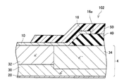
図1に示すように、本実施例のSBD2は、半導体基板4と、上面電極10と、下面電極20と、を有する。
(First embodiment)
As shown in FIG. 1, the SBD 2 of this example includes a
半導体基板4は、Ga2O3によって形成されているn型の半導体基板である。半導体基板4は、高濃度層30と、中濃度層32と、低濃度層34とを有している。高濃度層30、中濃度層32、低濃度層34は、いずれもn型の半導体層である。変形例では、低濃度層34は、i型の半導体層であってもよい。
The
高濃度層30は、半導体基板4の下面全面に露出する範囲に形成されている。中濃度層32は、高濃度層30上の一部に形成されている。中濃度層32の上面は半導体基板4の上面に露出する。中濃度層32のn型不純物濃度は、高濃度層30のn型不純物濃度よりも低い。ここでいう不純物濃度は、当該層における平均不純物濃度のことを意味する。中濃度層32は、SBD2のドリフト層として機能する。低濃度層34は、高濃度層30上において中濃度層32を一巡する範囲に形成されている。低濃度層34は、半導体基板4の側面(図示省略)に到達している。低濃度層34の上面も、半導体基板4の上面に露出する。低濃度層34のn型不純物濃度は、中濃度層32のn型不純物濃度よりも低い。また、中濃度層32の比誘電率は、低濃度層34の比誘電率よりも小さい。
The
上面電極10は、半導体基板4の上面の一部に接して形成されている。上面電極10は、中濃度層32の上面にショットキー接触している。ただし、上面電極10と半導体基板4とが接している接触領域は、中濃度層32を越えて低濃度層34上に及んでいる。上面電極10は、SBD2のアノード電極として機能する。
The
下面電極20は、半導体基板4の下面に接して形成されている。下面電極20は、高濃度層30の下面にオーミック接触している。下面電極20は、SBD2のカソード電極として機能する。本実施例では、半導体基板4の下面の全域に下面電極20が形成されている。変形例では、下面電極20は、半導体基板4の下面の一部に接していてもよい。
The
次に、本実施例のSBD2の動作を説明する。上面電極10と下面電極20の間に、上面電極10がプラスとなる電圧(即ち順方向バイアス)を印加すると、半導体基板4側から上面電極10に向かって電子が移動する。これにより、上面電極10から下面電極20に電流が流れる。
Next, the operation of the
また、上面電極10と下面電極20の間に、下面電極20がプラスとなる電圧(即ち逆方向バイアス)を印加すると、図2に示すように、ショットキー界面(即ち、上面電極10と中濃度層32との界面)から半導体基板4内に向けて延びる空乏層90が形成される。空乏層90は、中濃度層32及び低濃度層34内に形成されるが、n型不純物濃度が高い高濃度層30内には延びない。また、低濃度層34は、中濃度層32よりもn型不純物濃度が低いため、低濃度層34内では中濃度層32内に比べて空乏層90が延びやすい。図2では、空乏層90内の電位分布を示す等電位線を仮想的に図示している(図中の破線参照)。低濃度層34の比誘電率は中濃度層32の比誘電率よりも大きいため、図2に示すように、低濃度層34内では、中濃度層32内に比べて、等電位線同士の間隔が比較的大きい。また、上記の通り、低濃度層34は、高濃度層30上において中濃度層32を一巡する範囲に形成されており、高濃度層30と離間していない。そのため、上面電極10の端部近傍の電位分布の間隔(即ち、等電位線の間隔)がほぼ一定になり、上面電極10の端部近傍における電位の変化が不規則になり難くなる。そのため、上面電極10の端部近傍における電界集中を十分に緩和することができる。そのため、本実施例のSBD2では、上面電極10の端部近傍にp型半導体層を形成することなく、高い耐圧を実現することができる。また、本実施例では、半導体基板4が、p型半導体層を形成することが困難な材料であるGa2O3によって形成されているため、p型半導体層を利用しない本実施例のSBD2の構造が特に有用である。
Further, when a voltage (that is, reverse bias) that causes the
(第2実施例)
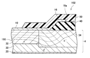
続いて、図3、図4を参照して、第2実施例のSBD102について、第1実施例と異なる点を中心に説明する。図3、図4では、第1実施例のSBD2と同様の要素は図1と同じ符号を用いて示し、詳細な説明を省略する。本実施例のSBD102は、層間絶縁膜40と、フィールドプレート電極16と、保護膜50とをさらに有する点で、第1実施例のSBD2とは異なる。
(Second embodiment)
Next, with reference to FIGS. 3 and 4, the
層間絶縁膜40は、半導体基板4の上面のうち、上面電極10と接していない範囲に配置されている。層間絶縁膜40は、ZrO2によって形成されている。変形例では、層間絶縁膜40はHfO2によって形成されていてもよい。層間絶縁膜40の比誘電率はSiO2の比誘電率よりも大きく、また、低濃度層34の比誘電率よりも大きい。
The
フィールドプレート電極16は、上面電極10と連続して形成されている。フィールドプレート電極16は、層間絶縁膜40を介して低濃度層34と対向している。フィールドプレート電極16の端部(即ち、上面電極10と反対側の端部)16aは、低濃度層34の上方に位置している。
The
保護膜50は、上面電極10の一部と、フィールドプレート電極16と、層間絶縁膜40の一部とを覆う絶縁膜である。保護膜50は、ポリイミドによって形成されている。
The
次に、本実施例のSBD102の動作を説明する。SBD102に順方向バイアスを印加する場合の動作は第1実施例のSBD2の場合と同様であるため、説明を省略する。一方、SBD102に逆方向バイアスを印加すると、図4に示すように、半導体基板4及び層間絶縁膜40内に延びる空乏層190が形成される。本実施例では、上面電極10と連続しているフィールドプレート電極16が設けられているため、空乏層190は上面電極10の端部から側方に離れた位置まで延びる。このため、上面電極10への端部近傍への電界集中をさらに緩和することができる。また、フィールドプレート電極16の上面電極10と反対側の端部16aが低濃度層34の上方に位置しているため、フィールドプレート電極16の端部16a近傍への電界集中も十分に緩和することができる。また、上記の通り、層間絶縁膜40の比誘電率は、SiO2の比誘電率よりも大きい。そのため、層間絶縁膜40における空乏層190内の等電位線の間隔が比較的広くなる。これにより、上面電極10への端部近傍への電界集中の緩和効果が十分に発揮される。従って、上記の通り、本実施例のSBD102によると、上面電極10への端部近傍への電界集中をさらに緩和することができるとともに、フィールドプレート電極16の端部16a近傍への電界集中も十分に緩和することができる。そのため、本実施例のSBD102でも、高い耐圧を実現することができる。
Next, the operation of the
(第3実施例)
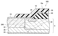
続いて、図5、図6を参照して、第3実施例のSBD202について、第2実施例と異なる点を中心に説明する。図5、図6でも、上記の各実施例のSBD2、102と同様の要素は同じ符号を用いて示し、詳細な説明を省略する。本実施例のSBD202は、低濃度層34内に、絶縁層36がさらに備えられている点が第2実施例のSBD102と異なる。
(Third embodiment)
Next, with reference to FIGS. 5 and 6, the
絶縁層36は、低濃度層34内において、中濃度層32を一巡する範囲に形成されている。絶縁層36は、低濃度層34にFeをドープすることによって形成される。本実施例では、絶縁層36は、半導体基板4の上面近傍に留まり、高濃度層30からは離間している。絶縁層36の比誘電率は、層間絶縁膜40の比誘電率よりも大きい。本実施例では、上面電極10と半導体基板4とが接している接触領域の端部は、絶縁層36上に位置している。
The insulating
次に、本実施例のSBD202の動作を説明する。SBD202に順方向バイアスを印加する場合の動作も、上記の各実施例のSBD2、102と同様であるため、詳しい説明を省略する。一方、SBD202に逆方向バイアスを印加すると、図6に示すように、半導体基板4及び層間絶縁膜40内に延びる空乏層290が形成される。本実施例では、低濃度層34内に絶縁層36が設けられているため、上面電極10の端部近傍への電界集中がより緩和される。そのため、本実施例のSBD202でも、高い耐圧を実現することができる。
Next, the operation of the
(第4実施例)
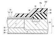
続いて、図7を参照して、第4実施例のSBD302について、第3実施例と異なる点を中心に説明する。図7でも、上記の各実施例のSBD2、102、202と同様の要素は同じ符号を用いて示し、詳細な説明を省略する。本実施例のSBD302では、上面電極10が、ショットキー電極膜12と積層電極膜14とを積層した構造を有する点が第3実施例とは異なる。
(Fourth embodiment)
Next, with reference to FIG. 7, the
図7に示すように、ショットキー電極膜12は、半導体基板4の上面に接している。ショットキー電極膜12は、中濃度層32の上面にショットキー接触している。ただし、ショットキー電極膜12と半導体基板4とが接している接触領域は、中濃度層32を越えて低濃度層34上に及んでいる。また、ショットキー電極膜12の端部は、層間絶縁膜40によって覆われている。ショットキー電極膜12の端部を覆っている側の層間絶縁膜40の端部は、低濃度層34上に位置している。積層電極膜14は、層間絶縁膜40で覆われていないショットキー電極膜12に積層されている。積層電極膜14は、フィールドプレート電極16に連続している。
As shown in FIG. 7, the
本実施例のSBD302の動作は、第3実施例のSBD202の動作とほぼ同様であるため、詳しい説明を省略する。上記の通り、本実施例のSBD302では、ショットキー電極膜12の端部が層間絶縁膜40によって覆われている。そのため、SBD302を製造する際に、半導体基板4の上面にショットキー電極膜12を形成した後に層間絶縁膜40を形成することができる。そのため、半導体基板4の上面が清浄である間にショットキー電極膜12を形成することができ、安定したショットキー界面を得ることができる。また、上記の通り、ショットキー電極膜12の端部を覆う側の層間絶縁膜40の端部は、低濃度層34上に位置しており、中濃度層32上には位置しない。そのため、SBD302に順方向バイアスを印加する場合に、導通抵抗が大きくなることもない。
Since the operation of the
以上、本明細書に開示の技術の具体例を詳細に説明したが、これらは例示に過ぎず、特許請求の範囲を限定するものではない。特許請求の範囲に記載の技術には、以上に例示した具体例を様々に変形、変更したものが含まれる。例えば、以下の変形例を採用してもよい。 As mentioned above, although the specific example of the technique disclosed by this specification was demonstrated in detail, these are only illustrations and do not limit a claim. The technology described in the claims includes various modifications and changes of the specific examples illustrated above. For example, the following modifications may be adopted.
(変形例1)上記の第1〜第3実施例においても、第4実施例と同様に、上面電極10が、半導体基板4の上面に接するショットキー電極膜と、ショットキー電極膜の上面に積層される積層電極膜とを有していてもよい。また、この場合において、フィールドプレート電極16が、ショットキー電極膜と連続する第1膜と、積層電極膜と連続し、第1膜の上面に積層される第2膜とを有していてもよい。
(Modification 1) Also in the first to third embodiments, as in the fourth embodiment, the
(変形例2)半導体基板4は、GaN,Si,SiC等、Ga2O3以外の材料によって形成されていてもよい。特に、半導体基板4がSi又はSiCによって形成される変形例においては、第2〜第4実施例の層間絶縁膜40と低濃度層34との間に熱酸化膜をさらに形成してもよい。ただし、半導体基板4が、p型半導体層を形成することが困難な材料であるGaN,Ga2O3によって形成されている場合、p型半導体層を利用しない本明細書に開示の構造が特に有用である。
(Modification 2) The
(変形例3)低濃度層34は、半導体基板4の側面に到達していなくてもよい。一般的に言うと、低濃度層34は、高濃度層30上において中濃度層32を一巡する範囲に形成されていればよく、上面電極10と半導体基板4の接触領域が中濃度層32を越えて低濃度層34上に及んでいればよい。
(Modification 3) The
本明細書が開示する技術要素について、以下に列記する。なお、以下の各技術要素は、それぞれ独立して有用なものである。 The technical elements disclosed in this specification are listed below. The following technical elements are each independently useful.
本明細書が開示するダイオードにおいて、低濃度層内において中濃度層を一巡する範囲に形成されている絶縁層をさらに備えていてもよい。接触領域の端部が、絶縁層上に位置していてもよい。 The diode disclosed in the present specification may further include an insulating layer formed in a range that goes around the intermediate concentration layer in the low concentration layer. The end of the contact area may be located on the insulating layer.
この構成によると、絶縁層が備えられていることによって、上面電極の端部近傍への電界集中をより緩和することができる。 According to this configuration, since the insulating layer is provided, electric field concentration near the end portion of the upper surface electrode can be further reduced.
本明細書が開示するダイオードにおいて、低濃度層に層間絶縁膜を介して対向するとともに上面電極に接続されているフィールドプレート電極をさらに備えていてもよい。フィールドプレート電極の上面電極と反対側の端部が、低濃度層上に位置していてもよい。 The diode disclosed in the present specification may further include a field plate electrode that faces the low-concentration layer via an interlayer insulating film and is connected to the upper surface electrode. The end of the field plate electrode opposite to the upper surface electrode may be located on the low concentration layer.
この構成によると、フィールドプレート電極が備えられているため、逆バイアス印加時に、空乏層が上面電極の端部から側方に離れた位置まで延びる。従って、上面電極への端部近傍への電界集中をさらに緩和することができる。また、フィールドプレート電極の上面電極と反対側の端部が低濃度層上に位置しているため、フィールドプレート電極の端部近傍への電界集中も十分に緩和することができる。 According to this configuration, since the field plate electrode is provided, the depletion layer extends to a position away from the end of the upper electrode to the side when a reverse bias is applied. Therefore, the electric field concentration near the end on the upper surface electrode can be further alleviated. In addition, since the end of the field plate electrode opposite to the upper surface electrode is located on the low concentration layer, electric field concentration near the end of the field plate electrode can be sufficiently reduced.
層間絶縁膜の比誘電率がSiO2の比誘電率よりも大きくてもよい。 The relative dielectric constant of the interlayer insulating film may be larger than the relative dielectric constant of SiO 2 .
この構成によると、層間絶縁膜における空乏層内の電位分布の間隔(即ち、等電位線の間隔)が比較的広くなる。そのため、上面電極10への端部近傍への電界集中の緩和効果が十分に発揮される。
According to this configuration, the potential distribution interval in the depletion layer in the interlayer insulating film (that is, the equipotential line interval) is relatively wide. Therefore, the effect of alleviating the concentration of the electric field in the vicinity of the end on the
本明細書または図面に説明した技術要素は、単独であるいは各種の組み合わせによって技術的有用性を発揮するものであり、出願時請求項記載の組み合わせに限定されるものではない。また、本明細書または図面に例示した技術は複数目的を同時に達成するものであり、そのうちの一つの目的を達成すること自体で技術的有用性を持つものである。 The technical elements described in this specification or the drawings exhibit technical usefulness alone or in various combinations, and are not limited to the combinations described in the claims at the time of filing. In addition, the technology illustrated in the present specification or the drawings achieves a plurality of objects at the same time, and has technical utility by achieving one of the objects.
2:SBD
4:半導体基板
10:上面電極
12:ショットキー電極膜
14:積層電極膜
16:フィールドプレート電極
16a:端部
20:下面電極
30:高濃度層
32:中濃度層
34:低濃度層
36:絶縁層
40:層間絶縁膜
50:保護膜
90:空乏層
102:SBD
190:空乏層
202:SBD
290:空乏層
302:SBD
2: SBD
4: Semiconductor substrate 10: Upper surface electrode 12: Schottky electrode film 14: Laminated electrode film 16:
190: Depletion layer 202: SBD
290: Depletion layer 302: SBD
Claims (4)
半導体基板と、
前記半導体基板の上面の一部に接している上面電極と、
前記半導体基板の下面の少なくとも一部に接している下面電極を備えており、
前記半導体基板が、
前記下面電極にオーミック接触するn型の高濃度層と、
前記高濃度層上の一部に形成されており、前記高濃度層よりn型不純物濃度が低いn型の中濃度層と、
前記高濃度層上において前記中濃度層を一巡する範囲に形成されており、前記中濃度層よりn型不純物濃度が低いn型の低濃度層を備えており、
前記上面電極が、前記中濃度層の上面にショットキー接触しており、
前記上面電極と前記半導体基板が接している接触領域が、前記中濃度層を越えて前記低濃度層上に及んでいる、
ダイオード。 A diode,
A semiconductor substrate;
An upper surface electrode in contact with a part of the upper surface of the semiconductor substrate;
Comprising a lower surface electrode in contact with at least a portion of the lower surface of the semiconductor substrate;
The semiconductor substrate is
An n-type high concentration layer in ohmic contact with the lower surface electrode;
An n-type medium concentration layer formed on a part of the high concentration layer and having an n-type impurity concentration lower than that of the high concentration layer;
The n-type low-concentration layer is formed on the high-concentration layer so as to go around the medium-concentration layer, and has an n-type impurity concentration lower than that of the medium-concentration layer,
The upper surface electrode is in Schottky contact with the upper surface of the intermediate concentration layer;
The contact region where the upper surface electrode and the semiconductor substrate are in contact extends over the low concentration layer beyond the intermediate concentration layer,
diode.
前記接触領域の端部が、前記絶縁層上に位置している請求項1に記載のダイオード。 In the low concentration layer further comprises an insulating layer formed in a range that makes a round of the intermediate concentration layer,
The diode according to claim 1, wherein an end of the contact region is located on the insulating layer.
前記フィールドプレート電極の前記上面電極と反対側の端部が、前記低濃度層上に位置している、請求項1または2に記載のダイオード。 Further comprising a field plate electrode facing the low concentration layer via an interlayer insulating film and connected to the upper surface electrode,
The diode according to claim 1, wherein an end portion of the field plate electrode opposite to the upper surface electrode is located on the low concentration layer.
Priority Applications (3)
| Application Number | Priority Date | Filing Date | Title |
|---|---|---|---|
| JP2016018117A JP2017139293A (en) | 2016-02-02 | 2016-02-02 | diode |
| PCT/IB2017/000049 WO2017134508A1 (en) | 2016-02-02 | 2017-01-31 | Schottky diode |
| US16/072,417 US20190035944A1 (en) | 2016-02-02 | 2017-01-31 | Schottky diode |
Applications Claiming Priority (1)
| Application Number | Priority Date | Filing Date | Title |
|---|---|---|---|
| JP2016018117A JP2017139293A (en) | 2016-02-02 | 2016-02-02 | diode |
Publications (2)
| Publication Number | Publication Date |
|---|---|
| JP2017139293A true JP2017139293A (en) | 2017-08-10 |
| JP2017139293A5 JP2017139293A5 (en) | 2018-05-17 |
Family
ID=58044102
Family Applications (1)
| Application Number | Title | Priority Date | Filing Date |
|---|---|---|---|
| JP2016018117A Pending JP2017139293A (en) | 2016-02-02 | 2016-02-02 | diode |
Country Status (3)
| Country | Link |
|---|---|
| US (1) | US20190035944A1 (en) |
| JP (1) | JP2017139293A (en) |
| WO (1) | WO2017134508A1 (en) |
Cited By (1)
| Publication number | Priority date | Publication date | Assignee | Title |
|---|---|---|---|---|
| US10418494B2 (en) | 2017-02-23 | 2019-09-17 | Toyota Jidosha Kabushiki Kaisha | Method of manufacturing semiconductor device |
Families Citing this family (4)
| Publication number | Priority date | Publication date | Assignee | Title |
|---|---|---|---|---|
| JP6560141B2 (en) * | 2016-02-26 | 2019-08-14 | トヨタ自動車株式会社 | Switching element |
| JP6560142B2 (en) * | 2016-02-26 | 2019-08-14 | トヨタ自動車株式会社 | Switching element |
| JP2018137394A (en) * | 2017-02-23 | 2018-08-30 | トヨタ自動車株式会社 | Method for manufacturing semiconductor device |
| CN110265486B (en) * | 2019-06-20 | 2023-03-24 | 中国电子科技集团公司第十三研究所 | Gallium oxide SBD terminal structure and preparation method |
Citations (4)
| Publication number | Priority date | Publication date | Assignee | Title |
|---|---|---|---|---|
| JPS5113580A (en) * | 1974-06-21 | 1976-02-03 | Westinghouse Electric Corp | Shotsutokiibarya daioodo |
| JPS554925A (en) * | 1978-06-26 | 1980-01-14 | Hitachi Ltd | Shot key barrier diode |
| JP2013102081A (en) * | 2011-11-09 | 2013-05-23 | Tamura Seisakusho Co Ltd | Schottky barrier diode |
| US20130161634A1 (en) * | 2011-12-22 | 2013-06-27 | Epowersoft, Inc. | Method and system for fabricating edge termination structures in gan materials |
Family Cites Families (2)
| Publication number | Priority date | Publication date | Assignee | Title |
|---|---|---|---|---|
| KR20130049919A (en) * | 2011-11-07 | 2013-05-15 | 현대자동차주식회사 | Silicon carbide schottky-barrier diode and method for manufacturing thr same |
| JP6269276B2 (en) * | 2014-04-11 | 2018-01-31 | 豊田合成株式会社 | Semiconductor device and method for manufacturing semiconductor device |
-
2016
- 2016-02-02 JP JP2016018117A patent/JP2017139293A/en active Pending
-
2017
- 2017-01-31 US US16/072,417 patent/US20190035944A1/en not_active Abandoned
- 2017-01-31 WO PCT/IB2017/000049 patent/WO2017134508A1/en active Application Filing
Patent Citations (4)
| Publication number | Priority date | Publication date | Assignee | Title |
|---|---|---|---|---|
| JPS5113580A (en) * | 1974-06-21 | 1976-02-03 | Westinghouse Electric Corp | Shotsutokiibarya daioodo |
| JPS554925A (en) * | 1978-06-26 | 1980-01-14 | Hitachi Ltd | Shot key barrier diode |
| JP2013102081A (en) * | 2011-11-09 | 2013-05-23 | Tamura Seisakusho Co Ltd | Schottky barrier diode |
| US20130161634A1 (en) * | 2011-12-22 | 2013-06-27 | Epowersoft, Inc. | Method and system for fabricating edge termination structures in gan materials |
Cited By (1)
| Publication number | Priority date | Publication date | Assignee | Title |
|---|---|---|---|---|
| US10418494B2 (en) | 2017-02-23 | 2019-09-17 | Toyota Jidosha Kabushiki Kaisha | Method of manufacturing semiconductor device |
Also Published As
| Publication number | Publication date |
|---|---|
| US20190035944A1 (en) | 2019-01-31 |
| WO2017134508A1 (en) | 2017-08-10 |
Similar Documents
| Publication | Publication Date | Title |
|---|---|---|
| TWI724160B (en) | Grooved metal oxide half-type Schottky diode | |
| JP5919033B2 (en) | Schottky barrier diode | |
| JP2018049951A (en) | Semiconductor device | |
| JP2017139293A (en) | diode | |
| JP7012137B2 (en) | Nitride semiconductor equipment | |
| JP2014216410A (en) | Semiconductor device | |
| JP2006318956A (en) | Semiconductor device having schottky diode | |
| TW201501328A (en) | Schottky diode structure | |
| JP5655932B2 (en) | Semiconductor device | |
| JP2017139289A (en) | diode | |
| JP2013161918A (en) | Semiconductor device | |
| JP5547022B2 (en) | Semiconductor device | |
| JP5406508B2 (en) | Horizontal SBD semiconductor device | |
| JP2016207829A (en) | Insulated gate type switching element | |
| JP2011009797A (en) | Semiconductor device with schottky diode | |
| JP7257912B2 (en) | semiconductor equipment | |
| US20110193099A1 (en) | Semiconductor device | |
| JP7147510B2 (en) | switching element | |
| JP2013175607A (en) | Schottky barrier diode | |
| JP2022139077A (en) | field effect transistor | |
| TWI565084B (en) | Ditch-type Schottky diodes | |
| JP2011023527A (en) | Semiconductor device | |
| JP5358141B2 (en) | Semiconductor device | |
| WO2014155565A1 (en) | Vertical semiconductor device | |
| JP4322183B2 (en) | Schottky barrier diode |
Legal Events
| Date | Code | Title | Description |
|---|---|---|---|
| A521 | Request for written amendment filed |
Free format text: JAPANESE INTERMEDIATE CODE: A523 Effective date: 20180328 |
|
| A621 | Written request for application examination |
Free format text: JAPANESE INTERMEDIATE CODE: A621 Effective date: 20180328 |
|
| A977 | Report on retrieval |
Free format text: JAPANESE INTERMEDIATE CODE: A971007 Effective date: 20190128 |
|
| A131 | Notification of reasons for refusal |
Free format text: JAPANESE INTERMEDIATE CODE: A131 Effective date: 20190205 |
|
| A02 | Decision of refusal |
Free format text: JAPANESE INTERMEDIATE CODE: A02 Effective date: 20190827 |


