JP2017135923A - Rotor for motor - Google Patents
Rotor for motor Download PDFInfo
- Publication number
- JP2017135923A JP2017135923A JP2016015541A JP2016015541A JP2017135923A JP 2017135923 A JP2017135923 A JP 2017135923A JP 2016015541 A JP2016015541 A JP 2016015541A JP 2016015541 A JP2016015541 A JP 2016015541A JP 2017135923 A JP2017135923 A JP 2017135923A
- Authority
- JP
- Japan
- Prior art keywords
- slot
- permanent magnet
- region
- magnet
- rotor
- Prior art date
- Legal status (The legal status is an assumption and is not a legal conclusion. Google has not performed a legal analysis and makes no representation as to the accuracy of the status listed.)
- Pending
Links
Images


Classifications
-
- Y—GENERAL TAGGING OF NEW TECHNOLOGICAL DEVELOPMENTS; GENERAL TAGGING OF CROSS-SECTIONAL TECHNOLOGIES SPANNING OVER SEVERAL SECTIONS OF THE IPC; TECHNICAL SUBJECTS COVERED BY FORMER USPC CROSS-REFERENCE ART COLLECTIONS [XRACs] AND DIGESTS
- Y02—TECHNOLOGIES OR APPLICATIONS FOR MITIGATION OR ADAPTATION AGAINST CLIMATE CHANGE
- Y02T—CLIMATE CHANGE MITIGATION TECHNOLOGIES RELATED TO TRANSPORTATION
- Y02T10/00—Road transport of goods or passengers
- Y02T10/60—Other road transportation technologies with climate change mitigation effect
- Y02T10/64—Electric machine technologies in electromobility
Landscapes
- Permanent Field Magnets Of Synchronous Machinery (AREA)
Abstract
Description
本発明は、モータ用ロータに関するものである。 The present invention relates to a motor rotor.
ブラシレスDCモータをはじめとする各種のモータを永久磁石の配設態様で分類した場合に、ロータコアに開設されたスロット内に永久磁石が配設された埋め込み磁石型モータ(IPMモータ)と、ロータコアの側面外周に筒状もしくは複数の円弧断面片の永久磁石が配設された表面磁石型モータ(SPMモータ)が存在しており、例えば、ハイブリット自動車や電気自動車用の駆動用モータとして、これらIPMモータ等が適用されている。 When various types of motors including brushless DC motors are classified according to the arrangement of permanent magnets, embedded magnet type motors (IPM motors) in which permanent magnets are arranged in slots established in the rotor core, and rotor cores There are surface magnet motors (SPM motors) in which permanent magnets having a cylindrical shape or a plurality of circular cross-section pieces are arranged on the outer periphery of the side surface. For example, these IPM motors are used as drive motors for hybrid cars and electric cars. Etc. are applied.
近時のハイブリッド自動車や電気自動車で使用される駆動用モータに関して言えば、モータの出力性能アップが追求されている中でたとえばその回転数や極数の増加が図られており、この回転数の増加等によって磁石に作用する磁界の変動率が大きくなり、その結果として上記渦電流が発生し易く、モータの損失の増加に繋がるといった課題が生じている。 Speaking of drive motors used in recent hybrid vehicles and electric vehicles, for example, the number of revolutions and the number of poles have been increased while the improvement in motor output performance has been pursued. Due to the increase, the fluctuation rate of the magnetic field acting on the magnet is increased, and as a result, the eddy current is likely to be generated, resulting in an increase in motor loss.
上記する渦電流の発生原因の一つとして、永久磁石とロータコアが面接触することにより、双方の接触面積が大きいために永久磁石とロータコアが電気的に通電することが挙げられる。より具体的には、スロット内に挿入された永久磁石とスロットの内壁面が接触することで永久磁石が電流経路となり、電磁鋼板の有する絶縁被膜を跨いだ大きな渦電流ループが生じ、渦電流損失の増大に繋がるというものである。 One of the causes of the generation of the eddy current is that the permanent magnet and the rotor core are in electrical contact with each other because the contact area between the permanent magnet and the rotor core is large. More specifically, the permanent magnet inserted into the slot and the inner wall surface of the slot come into contact with each other, so that the permanent magnet becomes a current path, and a large eddy current loop straddling the insulating coating of the magnetic steel sheet is generated, resulting in eddy current loss. This leads to an increase in
ここで、特許文献1,2には、上記する永久磁石とロータコアの接触面積を小さくすることで渦電流を低減する技術が開示されている。
Here,
特許文献1には、スロット内で径方向外方および内壁の延伸方向に対して傾斜した姿勢で磁石が挿入され、絶縁材で固定された回転電機用ロータが開示されている。
特許文献1に開示の回転電機用ロータによれば、磁石がロータコアと接触する部分を小さく限定することができ、磁石を介してロータコアに流れる渦電流ループ経路が大きく形成されるのを制限することができる。
According to the rotor for a rotating electrical machine disclosed in
一方、特許文献2には、ロータを構成する電磁鋼板の積層方向でスロット内に部分的に突起があり、この突起で磁石を保持し、磁石とスロットの接触面積を小さくする回転電機ロータが開示されている。
On the other hand,
このように、特許文献1,2に開示の技術によれば、ロータのスロットと磁石の接触面積を低減し、渦電流損失を低減することが可能になる。
Thus, according to the techniques disclosed in
ところで、IPMモータの場合、ステータ側からロータに流入してくる磁界(逆磁界)はロータのスロットに挿入された永久磁石の角部(永久磁石のステータ側の角部)に集中する傾向にある。 By the way, in the case of an IPM motor, the magnetic field (reverse magnetic field) flowing into the rotor from the stator side tends to concentrate on the corner of the permanent magnet inserted into the rotor slot (the corner on the stator side of the permanent magnet). .
したがって、仮に特許文献1,2に開示の技術を適用したとしても、永久磁石とスロットの接触が永久磁石のステータ側の角部の場合には、上記する渦電流損失低減効果が十分に得られない可能性がある。
Therefore, even if the techniques disclosed in
本発明は上記する問題に鑑みてなされたものであり、渦電流損失低減効果の高いモータ用ロータを提供することを目的とする。 The present invention has been made in view of the above problems, and an object thereof is to provide a motor rotor having a high effect of reducing eddy current loss.
前記目的を達成すべく、本発明によるモータ用ロータは、スロットに永久磁石が挿入されてなるモータ用ロータであって、前記スロットのうち、ステータ側から流入してくる逆磁界が相対的に大きな第1の領域では該スロットの内壁面と前記永久磁石が接触せず、前記スロットのうち、前記第1の領域以外の第2の領域では該スロットの内壁面と前記永久磁石が接触して該スロット内における該永久磁石の固定が図られているものである。 In order to achieve the above object, a motor rotor according to the present invention is a motor rotor in which a permanent magnet is inserted into a slot, and a reverse magnetic field flowing from the stator side in the slot is relatively large. In the first region, the inner wall surface of the slot and the permanent magnet are not in contact with each other, and in the second region other than the first region, the inner wall surface of the slot and the permanent magnet are in contact with each other in the first region. The permanent magnet is fixed in the slot.
本発明のモータ用ロータは、ステータ側から流入してくる逆磁界が相対的に大きな第1の領域では該スロットの内壁面と前記永久磁石が接触せず、それ以外の領域(第2の領域)にて双方を接触させ、スロット内で永久磁石を固定したことに特徴を有するものである。 In the motor rotor of the present invention, the inner wall surface of the slot does not contact the permanent magnet in the first region where the reverse magnetic field flowing from the stator side is relatively large, and the other region (second region) ), Both are brought into contact with each other, and the permanent magnet is fixed in the slot.
ここで、「ステータ側から流入してくる逆磁界が相対的に大きな第1の領域」は、たとえば平面視略矩形のスロットにおけるステータ側の2つの隅角領域や、平面視略矩形のスロットにおけるステータ側の2つの隅角領域のうちの一方の隅角領域のことを意味している。 Here, the “first region where the reverse magnetic field flowing in from the stator side is relatively large” refers to, for example, two corner regions on the stator side in a substantially rectangular slot in plan view, or in a slot in a substantially rectangular shape in plan view. It means one corner area of the two corner areas on the stator side.
このように、ステータ側からの逆磁界が流入する領域にスロットと永久磁石の接触箇所が存在しないことで、大きな渦電流ループの発生を解消もしくは抑制することが可能になる。 As described above, since there is no contact point between the slot and the permanent magnet in the region where the reverse magnetic field from the stator side flows, it is possible to eliminate or suppress the generation of a large eddy current loop.
第2の領域でスロットの内壁面と永久磁石を接触させる構成としては、永久磁石を2つの分割磁石から構成し、各分割磁石同士の接触面をテーパー状とし、スロット内に各分割磁石を挿入した後、分割磁石の側方に永久磁石固定用の樹脂等を注入して分割磁石の側方から内側に圧力を付与することで、テーパー面に沿って一方の分割磁石を第2の領域にあるスロットのステータ側の内壁面に当接させ、他方の分割磁石を第2の領域にあるスロットのロータ中心側の内壁面に当接させるといった形態が挙げられる。 In the second region, the inner wall surface of the slot and the permanent magnet are brought into contact with each other. The permanent magnet is composed of two divided magnets, the contact surface of each divided magnet is tapered, and each divided magnet is inserted into the slot. After that, by injecting a permanent magnet fixing resin or the like to the side of the split magnet and applying pressure from the side of the split magnet to the inside, one of the split magnets is moved to the second region along the tapered surface. There may be mentioned a configuration in which a certain slot is brought into contact with the inner wall surface on the stator side, and the other divided magnet is brought into contact with the inner wall surface on the rotor center side of the slot in the second region.
また、永久磁石を3つの分割磁石から構成してもよく、各分割磁石の接触面をテーパー状とし、中央の分割磁石がスロットのステータ側の内壁面の中央位置で当接し、他の左右の分割磁石がスロットのロータ中心側の内壁面の左右位置で当接することで、スロットのステータ側の左右の隅角部に永久磁石が当接しない永久磁石配置を形成することができる。 In addition, the permanent magnet may be composed of three divided magnets, the contact surface of each divided magnet is tapered, the central divided magnet contacts at the center position of the inner wall surface on the stator side of the slot, and the other left and right magnets Since the split magnets abut on the left and right positions of the inner wall surface of the slot on the rotor center side, it is possible to form a permanent magnet arrangement in which the permanent magnets do not abut on the left and right corners on the stator side of the slot.
また、他の形態として、スロットに1つもしくは2以上の突起を形成しておき、この突起で分割磁石が第2の領域にてスロットの内壁面と接触して固定される形態を挙げることができる。 As another form, there may be mentioned a form in which one or more protrusions are formed in the slot and the divided magnet is fixed in contact with the inner wall surface of the slot in the second region by the protrusion. it can.
さらに他の形態として、接着剤を用いて、分割磁石が第2の領域にてスロットの内壁面と接着剤を介して固定される形態を挙げることができる。 As another form, a form in which the split magnet is fixed to the inner wall surface of the slot via the adhesive in the second region using an adhesive can be mentioned.
上記する種々の形態では、スロットのステータ側の内壁面に当接した分割磁石の側方には、分割磁石がスロットのステータ側の内壁面に当接しない領域が形成されており、この領域が第1の領域となるように各分割磁石が配設される。 In the various forms described above, a region where the divided magnets do not contact the inner wall surface of the slot on the stator side is formed on the side of the divided magnets that contact the inner wall surface of the slot on the stator side. Each divided magnet is disposed so as to be the first region.
以上の説明から理解できるように、本発明のモータ用ロータによれば、ステータ側から流入してくる逆磁界が相対的に大きな第1の領域では該スロットの内壁面と永久磁石が接触せず、それ以外の第2の領域にてスロットの内壁面と永久磁石を接触させてスロット内で永久磁石を固定したことにより、ステータから流入してくる大きな逆磁界が通過する領域にスロットと永久磁石が接触していないことから、大きな渦電流ループの発生を解消でき、もって渦電流損失低減効果の高いモータ用ロータとなる。 As can be understood from the above description, according to the motor rotor of the present invention, the inner wall surface of the slot does not contact the permanent magnet in the first region where the reverse magnetic field flowing from the stator side is relatively large. In the other second region, the inner wall surface of the slot and the permanent magnet are brought into contact with each other, and the permanent magnet is fixed in the slot, so that the large counter magnetic field flowing from the stator passes through the slot and the permanent magnet. Therefore, the generation of a large eddy current loop can be eliminated, and the rotor for a motor having a high effect of reducing eddy current loss can be obtained.
以下、図面を参照して本発明のモータ用ロータの実施の形態を説明する。なお、図示例は1つの磁極を略Vの字状に配設された2つの永久磁石が形成するものであるが、1つの磁極を1つの永久磁石が構成する等、他の形態であってもよいことは勿論のことである。 Embodiments of a motor rotor according to the present invention will be described below with reference to the drawings. In the example shown in the drawing, one magnetic pole is formed by two permanent magnets arranged in a substantially V shape, but other forms such as one magnetic pole is formed by one permanent magnet. Of course, it is also good.
(モータ用ロータの実施の形態)
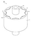
本発明のモータ用ロータの斜視図である。
図1で示すモータ用ロータ10はIPMモータ用のロータである。その製造方法は、複数の電磁鋼板を積層するに当たり、対応するスロット用開口を位置合わせしながら電磁鋼板を積層し、全体をかしめてロータコア1が形成される。なお、使用する電磁鋼板としては、珪素鋼板やそのほかの軟磁性材料から形成された鋼板が挙げられる。
(Embodiment of motor rotor)
It is a perspective view of the rotor for motors of the present invention.
A
各電磁鋼板は、その表面に絶縁被膜を有した広幅な電磁鋼板を図示する円盤状に打抜いて形成され、円盤状の電磁鋼板においても、略Vの字状の2つの磁石用スロット開口を一組としてこれを磁極数に応じた組数だけ打ち抜き加工にて形成する。なお、電磁鋼板はその上下2つの積層面に絶縁被膜を有していてもよいし、いずれか一方の積層面にのみ絶縁被膜を有していてもよいが、後者の場合には、電磁鋼板を積層した際に各電磁鋼板の間に絶縁被膜が存在するようにして積層する。 Each electromagnetic steel sheet is formed by punching a wide electromagnetic steel sheet having an insulating coating on the surface thereof into a disk shape as illustrated, and the disk-shaped electromagnetic steel sheet also has two substantially V-shaped slot openings for magnets. This is formed by punching as many as the number of sets corresponding to the number of magnetic poles. The electrical steel sheet may have an insulating coating on the upper and lower two laminated surfaces, or may have an insulating coating only on one of the laminated surfaces. In the latter case, the electrical steel sheet Are laminated such that an insulating coating exists between the electromagnetic steel sheets.
このようにして形成されたロータコア1の中央位置にはシャフト1bが固定され、外周側(不図示のステータ側)には、その周方向に磁極ごとに平面視略Vの字状に配設された2つのスロット1aが形成され、各スロット1aに永久磁石2が配設されてモータ用ロータ10が構成される。
The
スロット1aに配設される永久磁石2としては、希土類磁石やフェライト磁石、アルニコ磁石等を適用することができ、この希土類磁石としては、ネオジムに鉄とボロンを加えた3成分系のネオジム磁石、サマリウムとコバルトとの2成分系の合金からなるサマリウムコバルト磁石などを挙げることができる。
As the
次に、以下、図2〜4を参照してスロットと永久磁石の実施の形態を説明する。
図2(a)で示すように、スロット1aは、平面視矩形の開口の左右側に永久磁石2固定用の樹脂を注入するための側方開口(平面視が略大径、略三角形の領域)を有しているが、本明細書では、このような樹脂注入用の側方開口を含めて、平面視略矩形のスロットと称する。
Next, embodiments of the slot and the permanent magnet will be described below with reference to FIGS.
As shown in FIG. 2 (a), the
図示するスロット1aのうち、ステータ側の左右の隅角部には、ステータ側から流入する逆磁界Jが通過し易い。
In the illustrated
このように逆磁界Jが通過する左右の隅角領域を第1の領域A1、それ以外の領域を第2の領域A2とする。 The left and right corner areas through which the reverse magnetic field J passes are defined as the first area A1, and the other areas are defined as the second area A2.
図示するように、左右の側面にテーパー面を備えた分割磁石2a、左右いずれかの側面にテーパー面を備えた分割磁石2bを計3つ用意し、分割磁石2aを中央に配設し、分割磁石2bをその左右に配設するとともに、各テーパー面同士が接触するようにして3つの分割磁石2a,2bを配設して永久磁石2を構成する。
As shown in the figure, a total of three divided
そして、スロット1aの左右の側方開口から不図示の樹脂を注入することにより、樹脂圧Pにて左右の分割磁石2bがスロット中央側に押され、左右の分割磁石2bで押された中央の分割磁石2aはテーパー面に沿ってスロット1aのステータ側の内壁面に当接する。
Then, by injecting resin (not shown) from the left and right side openings of the
形成された永久磁石2は、左右の分割磁石2bが第2の領域A2であるスロット1aのロータ中央側の内壁面に当接し、中央の分割磁石2aが第2の領域A2であるスロット1aのステータ側の内壁面に当接し、これらが側方の樹脂にて位置決め固定される。
In the formed
このように、永久磁石2を構成する左右の分割磁石2bは第1の領域A1にてスロット1aの内壁面と接触しておらず、中央の分割磁石2aも当然に第1の領域A1にてスロット1aの内壁面と接触していないことから、大きな渦電流ループの発生を解消でき、もって渦電流損失低減効果の高いモータ用ロータ10となる。
Thus, the left and right divided
図2(b)で示す実施の形態は、2つの分割磁石2cがともに左右いずれかの側面にテーパー面を有しており、相互にテーパー面同士を当接させながらスロット1a内に配設され、側方から樹脂圧Pを受けて永久磁石2Bが形成されたものである。
In the embodiment shown in FIG. 2 (b), the two divided
この実施の形態は、ステータ側からの逆磁界Jがスロット1aのステータ側の左右いずれか一方の隅角部のみを通過する場合(したがって、第1の領域A1が左右いずれかに形成される場合)に適用されるものである。
In this embodiment, the reverse magnetic field J from the stator side passes through only one of the left and right corners on the stator side of the
図示例では、スロット1aの右側のステータ側隅角部に第1の領域A1が形成されるものであるが、右側の分割磁石2cは第1の領域A1にてスロット1aの内壁面と接触していないことから、大きな渦電流ループの発生を解消でき、もって渦電流損失低減効果の高いモータ用ロータ10となる。
In the illustrated example, the first region A1 is formed at the stator-side corner on the right side of the
図3(a)で示す実施の形態は、スロット1aがステータ側の側面に2つの突起1a’を備えており、この2つの突起1a’にて中央の分割磁石2dの位置決めが図られ、中央の分割磁石2dの左右に他の分割磁石2dが配設され、これら他の分割磁石2dは側方から樹脂圧Pを受けて永久磁石2Cが構成されたものである。
In the embodiment shown in FIG. 3A, the
図示例では、スロット1aの左右のステータ側隅角部に第1の領域A1が形成されるものの、左右の分割磁石2dは第1の領域A1にてスロット1aの内壁面と接触していないことから、大きな渦電流ループの発生を解消でき、もって渦電流損失低減効果の高いモータ用ロータ10となる。
In the illustrated example, the first region A1 is formed at the left and right stator corners of the
図3(b)で示す実施の形態は、スロット1aがステータ側の側面の中央位置に1つの突起1a’を備えており、この突起1a’にて左右の分割磁石2eの位置決めが図られ、これら2つの分割磁石2eは側方から樹脂圧Pを受けて永久磁石2Dが構成されたものである。
In the embodiment shown in FIG. 3B, the
図示例では、スロット1aの右側のステータ側隅角部に第1の領域A1が形成されるものの、右側の分割磁石2eは第1の領域A1にてスロット1aの内壁面と接触していないことから、大きな渦電流ループの発生を解消でき、もって渦電流損失低減効果の高いモータ用ロータ10となる。
In the illustrated example, the first region A1 is formed at the stator-side corner on the right side of the
図4(a)で示す実施の形態は、3つの分割磁石2dがスロット1a内に挿入され、左右の分割磁石2dがスロット1aのロータ中央側の内壁面に接着剤3を介して固定され、中央の分割磁石2dはスロット1aの中央にてステータ側の内壁面に接触して永久磁石2Cが構成されたものである。
In the embodiment shown in FIG. 4A, three divided
図2(a),図3(a)で示す実施の形態と同様、スロット1aの左右のステータ側隅角部に第1の領域A1が形成されるものの、左右の分割磁石2dは第1の領域A1にてスロット1aの内壁面と接触していないことから、大きな渦電流ループの発生を解消でき、もって渦電流損失低減効果の高いモータ用ロータ10となる。
Similar to the embodiment shown in FIGS. 2A and 3A, the first region A1 is formed at the left and right stator corners of the
図4(b)で示す実施の形態は、2つの分割磁石2eがスロット1a内に挿入され、右側の分割磁石2eがスロット1aのロータ中央側の内壁面に接着剤3を介して固定され、左側の分割磁石2eは樹脂圧Pを受けながらスロット1aのステータ側の内壁面に接触して永久磁石2Dが構成されたものである。
In the embodiment shown in FIG. 4B, two divided
図2(b),図3(b)で示す実施の形態と同様、図示例では、スロット1aの右側のステータ側隅角部に第1の領域A1が形成されるものの、右側の分割磁石2eは第1の領域A1にてスロット1aの内壁面と接触していないことから、大きな渦電流ループの発生を解消でき、もって渦電流損失低減効果の高いモータ用ロータ10となる。
Similar to the embodiment shown in FIGS. 2B and 3B, in the illustrated example, the first region A1 is formed at the stator-side corner on the right side of the
以上、本発明の実施の形態を図面を用いて詳述してきたが、具体的な構成はこの実施形態に限定されるものではなく、本発明の要旨を逸脱しない範囲における設計変更等があっても、それらは本発明に含まれるものである。 The embodiment of the present invention has been described in detail with reference to the drawings. However, the specific configuration is not limited to this embodiment, and there are design changes and the like without departing from the gist of the present invention. They are also included in the present invention.
1…ロータコア、1a…スロット、1a’…突起、1b…シャフト、2,2B,2C,2D…永久磁石、2a,2b,2c,2d,2e…分割磁石、J…逆磁界、A1…第1の領域、A2…第2の領域
DESCRIPTION OF
Claims (1)
前記スロットのうち、ステータ側から流入してくる逆磁界が相対的に大きな第1の領域では該スロットの内壁面と前記永久磁石が接触せず、
前記スロットのうち、前記第1の領域以外の第2の領域では該スロットの内壁面と前記永久磁石が接触して該スロット内における該永久磁石の固定が図られている、モータ用ロータ。 A rotor for a motor in which a permanent magnet is inserted into a slot,
Among the slots, in the first region where the reverse magnetic field flowing from the stator side is relatively large, the inner wall surface of the slot and the permanent magnet do not contact,
A rotor for a motor, wherein an inner wall surface of the slot and the permanent magnet are in contact with each other in a second region other than the first region, and the permanent magnet is fixed in the slot.
Priority Applications (1)
| Application Number | Priority Date | Filing Date | Title |
|---|---|---|---|
| JP2016015541A JP2017135923A (en) | 2016-01-29 | 2016-01-29 | Rotor for motor |
Applications Claiming Priority (1)
| Application Number | Priority Date | Filing Date | Title |
|---|---|---|---|
| JP2016015541A JP2017135923A (en) | 2016-01-29 | 2016-01-29 | Rotor for motor |
Publications (1)
| Publication Number | Publication Date |
|---|---|
| JP2017135923A true JP2017135923A (en) | 2017-08-03 |
Family
ID=59503943
Family Applications (1)
| Application Number | Title | Priority Date | Filing Date |
|---|---|---|---|
| JP2016015541A Pending JP2017135923A (en) | 2016-01-29 | 2016-01-29 | Rotor for motor |
Country Status (1)
| Country | Link |
|---|---|
| JP (1) | JP2017135923A (en) |
Cited By (1)
| Publication number | Priority date | Publication date | Assignee | Title |
|---|---|---|---|---|
| DE102018210967A1 (en) * | 2018-07-04 | 2020-01-09 | Brose Fahrzeugteile GmbH & Co. Kommanditgesellschaft, Würzburg | rotor |
-
2016
- 2016-01-29 JP JP2016015541A patent/JP2017135923A/en active Pending
Cited By (1)
| Publication number | Priority date | Publication date | Assignee | Title |
|---|---|---|---|---|
| DE102018210967A1 (en) * | 2018-07-04 | 2020-01-09 | Brose Fahrzeugteile GmbH & Co. Kommanditgesellschaft, Würzburg | rotor |
Similar Documents
| Publication | Publication Date | Title |
|---|---|---|
| JP4561770B2 (en) | Axial gap type rotating electrical machine and manufacturing method thereof | |
| US9935510B2 (en) | Axial-type rotary electric machine | |
| JP2016010176A (en) | Motor | |
| JP4673825B2 (en) | Embedded magnet rotor and manufacturing method of embedded magnet rotor | |
| JPWO2017061305A1 (en) | Rotor and rotating electric machine | |
| EP2763285A2 (en) | Permanent magnet embedded type rotor for rotating electrical machine and rotating electrical machine having permanent magnet embedded type rotor | |
| JP2014045634A (en) | Rotor and rotary electric machine including the same | |
| JP2018519782A (en) | Permanent magnet motor | |
| JP2013132124A (en) | Core for field element | |
| JP2005051929A (en) | Motor | |
| JP5258944B2 (en) | Electric motor and method of manufacturing split stator core | |
| US20180198330A1 (en) | Permanent magnet motor | |
| JP5857837B2 (en) | Permanent magnet rotating electric machine | |
| JP2017135923A (en) | Rotor for motor | |
| JP5444756B2 (en) | IPM motor rotor and IPM motor | |
| JP2015133825A (en) | Rotor for rotary electric machine | |
| JP5353804B2 (en) | Axial gap type rotating electrical machine and manufacturing method thereof | |
| JP7038527B2 (en) | Manufacturing method of magnetic wedge for rotary electric machine, magnetic wedge for rotary electric machine, and rotary electric machine | |
| JP5750995B2 (en) | Synchronous motor | |
| JP2013099089A (en) | Rotor for motor and method of manufacturing the same | |
| JP2011244687A (en) | Manufacturing method of electric motor and split stator iron core | |
| JP2011244688A (en) | Manufacturing method of electric motor and split stator iron core | |
| JP2014143797A (en) | Magnet embedded rotary electric machine | |
| JP2012235608A (en) | Synchronous motor | |
| WO2023105701A1 (en) | Rotor of rotary electric machine |