JP2013099089A - Rotor for motor and method of manufacturing the same - Google Patents
Rotor for motor and method of manufacturing the same Download PDFInfo
- Publication number
- JP2013099089A JP2013099089A JP2011239254A JP2011239254A JP2013099089A JP 2013099089 A JP2013099089 A JP 2013099089A JP 2011239254 A JP2011239254 A JP 2011239254A JP 2011239254 A JP2011239254 A JP 2011239254A JP 2013099089 A JP2013099089 A JP 2013099089A
- Authority
- JP
- Japan
- Prior art keywords
- rotor
- electromagnetic steel
- permanent magnet
- motor
- steel sheet
- Prior art date
- Legal status (The legal status is an assumption and is not a legal conclusion. Google has not performed a legal analysis and makes no representation as to the accuracy of the status listed.)
- Pending
Links
- 238000004519 manufacturing process Methods 0.000 title claims abstract description 24
- 229910000831 Steel Inorganic materials 0.000 claims abstract description 74
- 239000010959 steel Substances 0.000 claims abstract description 74
- 238000010030 laminating Methods 0.000 claims abstract description 7
- 238000000576 coating method Methods 0.000 claims description 25
- 239000011248 coating agent Substances 0.000 claims description 24
- 238000000034 method Methods 0.000 claims description 8
- 238000009413 insulation Methods 0.000 abstract 1
- 238000003475 lamination Methods 0.000 abstract 1
- 238000005452 bending Methods 0.000 description 8
- 239000011347 resin Substances 0.000 description 5
- 229920005989 resin Polymers 0.000 description 5
- 229910000976 Electrical steel Inorganic materials 0.000 description 4
- 238000004080 punching Methods 0.000 description 4
- 238000010008 shearing Methods 0.000 description 4
- 229910000531 Co alloy Inorganic materials 0.000 description 1
- 229910052772 Samarium Inorganic materials 0.000 description 1
- 229910000828 alnico Inorganic materials 0.000 description 1
- 229910002056 binary alloy Inorganic materials 0.000 description 1
- 239000010941 cobalt Substances 0.000 description 1
- GUTLYIVDDKVIGB-UHFFFAOYSA-N cobalt atom Chemical compound [Co] GUTLYIVDDKVIGB-UHFFFAOYSA-N 0.000 description 1
- 239000000470 constituent Substances 0.000 description 1
- 230000000694 effects Effects 0.000 description 1
- 239000000696 magnetic material Substances 0.000 description 1
- 230000002093 peripheral effect Effects 0.000 description 1
- 229910052761 rare earth metal Inorganic materials 0.000 description 1
- 150000002910 rare earth metals Chemical class 0.000 description 1
- KZUNJOHGWZRPMI-UHFFFAOYSA-N samarium atom Chemical compound [Sm] KZUNJOHGWZRPMI-UHFFFAOYSA-N 0.000 description 1
- 229910000938 samarium–cobalt magnet Inorganic materials 0.000 description 1
- 229910000859 α-Fe Inorganic materials 0.000 description 1
Images

Classifications
-
- Y—GENERAL TAGGING OF NEW TECHNOLOGICAL DEVELOPMENTS; GENERAL TAGGING OF CROSS-SECTIONAL TECHNOLOGIES SPANNING OVER SEVERAL SECTIONS OF THE IPC; TECHNICAL SUBJECTS COVERED BY FORMER USPC CROSS-REFERENCE ART COLLECTIONS [XRACs] AND DIGESTS
- Y02—TECHNOLOGIES OR APPLICATIONS FOR MITIGATION OR ADAPTATION AGAINST CLIMATE CHANGE
- Y02T—CLIMATE CHANGE MITIGATION TECHNOLOGIES RELATED TO TRANSPORTATION
- Y02T10/00—Road transport of goods or passengers
- Y02T10/60—Other road transportation technologies with climate change mitigation effect
- Y02T10/64—Electric machine technologies in electromobility
Landscapes
- Iron Core Of Rotating Electric Machines (AREA)
- Manufacture Of Motors, Generators (AREA)
- Permanent Field Magnets Of Synchronous Machinery (AREA)
Abstract
Description
本発明は、モータ用ロータとその製造方法に関するものである。 The present invention relates to a motor rotor and a method for manufacturing the same.
ブラシレスDCモータをはじめとする各種のモータを永久磁石の配設態様で分類した場合に、ロータコアに開設されたスロット内に永久磁石が配設された埋め込み磁石型モータ(IPMモータ)と、ロータコアの側面外周に筒状もしくは複数の円弧断面片の永久磁石が配設された表面磁石型モータ(SPMモータ)が存在しており、例えば、ハイブリット自動車や電気自動車用の駆動用モータとして、これらIPMモータ等が適用されている。 When various types of motors including brushless DC motors are classified according to the arrangement of permanent magnets, embedded magnet type motors (IPM motors) in which permanent magnets are arranged in slots established in the rotor core, and rotor cores There are surface magnet motors (SPM motors) in which permanent magnets having a cylindrical shape or a plurality of arc-shaped cross-section pieces are disposed on the outer periphery of the side surface. Etc. are applied.
近時のハイブリッド自動車や電気自動車で使用される駆動用モータに関して言えば、モータの出力性能アップが追求されている中でたとえばその回転数や極数の増加が図られており、この回転数の増加等によって磁石に作用する磁界の変動率が大きくなり、その結果として上記渦電流が発生し易く、モータの損失の増加に繋がるといった課題が生じている。 Speaking of drive motors used in recent hybrid vehicles and electric vehicles, for example, the number of revolutions and the number of poles have been increased while the improvement in motor output performance has been pursued. Due to the increase, the fluctuation rate of the magnetic field acting on the magnet is increased, and as a result, the eddy current is likely to be generated, resulting in an increase in motor loss.
上記する渦電流の発生原因の一つとして、永久磁石とロータコアが面接触することにより、双方の接触面積が大きいために永久磁石とロータコアが電気的に通電することが挙げられる。 One of the causes of the generation of the eddy current is that the permanent magnet and the rotor core are in electrical contact with each other because the contact area between the permanent magnet and the rotor core is large.
このことを図3を参照して説明する。図3aは、IPMモータ用ロータRの平面図を示しており、図3bは図3aのb−b矢視図であってロータRの縦断面図を示している。 This will be described with reference to FIG. 3A is a plan view of the rotor R for the IPM motor, and FIG. 3B is a view taken along the line bb in FIG.
図示するように、IPMモータ用ロータRは、永久磁石用のスロットSLを形成する開口が開設された複数の電磁鋼板MSを対応する開口同士を位置合わせしながらスロットSLを形成するようにして積層し、積層された電磁鋼板同士をかしめ等することによってできたロータコアRCと、スロットSL内に配設され、樹脂J等で固定された永久磁石Mとから構成されている。 As shown in the figure, the IPM motor rotor R is formed by laminating a plurality of electromagnetic steel plates MS having openings for forming slots SL for permanent magnets so as to form slots SL while aligning corresponding openings. The rotor core RC is formed by caulking laminated electromagnetic steel sheets, and the permanent magnet M is disposed in the slot SL and fixed with a resin J or the like.
電磁鋼板MSの上下の積層面、もしくはいずれか一方の積層面には絶縁被膜ICが形成されており、したがって、図3bで示すように、電磁鋼板MSが積層した姿勢において、各電磁鋼板MS同士は絶縁されることから、薄い厚みの電磁鋼板MS内にて微小な渦電流ECが形成されるに過ぎない。 The insulating coating IC is formed on the upper and lower laminated surfaces of the electromagnetic steel plates MS, or any one of the laminated surfaces. Therefore, as shown in FIG. Is insulated, only a minute eddy current EC is formed in the thin steel sheet MS.
しかしながら、スロットSL内に配設された永久磁石Mは、スロットSLを構成するいずれかの壁面と面接触した状態で充填された樹脂Jにて固定される可能性が極めて高く、永久磁石Mを介してそれぞれの電磁鋼板MSが電気的に通電し、面接触する電磁鋼板MSの端面と永久磁石Mとの間で大きな渦電流EC’が形成され、これが渦電流損失の増加の大きな原因となるのである。 However, the permanent magnet M disposed in the slot SL is very likely to be fixed by the resin J filled in a state of surface contact with any wall surface constituting the slot SL. Each of the electrical steel plates MS is electrically energized through the surface, and a large eddy current EC ′ is formed between the end face of the electrical steel plate MS in contact with the surface and the permanent magnet M, which causes a large increase in eddy current loss. It is.
ここで、特許文献1には、電磁鋼板を積層した姿勢でスロットをせん断加工にて形成した技術が開示されている。
Here,
このように電磁鋼板が積層されたロータコアに対してせん断加工にてスロットを形成する場合、このせん断加工の際に電磁鋼板の表面に形成された絶縁被膜が剥がれてしまい、さらに絶縁被膜が剥がれた電磁鋼板の端部にせん断方向に延びるバリが生じてしまう。特許文献1はこのバリを積極的に形成する技術であるが、このように電磁鋼板からなるバリによってスロット壁面が形成され、ここに永久磁石が配設されることにより、結果として図3bで示すように永久磁石とスロット壁面とが面接触する可能性が極めて高く、渦電流損失が増加するという既述の課題が生じることになる。
When a slot is formed by shearing the rotor core on which the electromagnetic steel sheets are laminated in this way, the insulating coating formed on the surface of the electromagnetic steel plate is peeled off during the shearing, and the insulating coating is further peeled off. A burr extending in the shear direction is generated at the end of the electromagnetic steel sheet.
本発明は上記する問題に鑑みてなされたものであり、積層された電磁鋼板と永久磁石が面接触して電気的に通電し、面接触する電磁鋼板の端面と永久磁石との間で大きな渦電流が形成され、渦電流損失が増加するといった課題を解消することのできるモータ用ロータとその製造方法を提供することを目的とする。 The present invention has been made in view of the problems described above, and the laminated electromagnetic steel sheets and permanent magnets are brought into surface contact and electrically energized, and a large vortex is generated between the end faces of the electromagnetic steel sheets in surface contact and the permanent magnets. It is an object of the present invention to provide a motor rotor and a method for manufacturing the same that can solve the problem that current is generated and eddy current loss increases.
前記目的を達成すべく、本発明によるモータ用ロータの製造方法は、電磁鋼板が積層されてなるロータコアと、永久磁石とからなるモータ用ロータの製造方法であって、少なくとも一方の積層面に絶縁被膜を有したそれぞれの電磁鋼板の永久磁石と接する端部を同一方向に折り曲げ加工し、積層してロータコアを製造し、永久磁石を配設してロータコアに固定するものである。 In order to achieve the above object, a method of manufacturing a rotor for a motor according to the present invention is a method of manufacturing a rotor for a motor including a rotor core formed by laminating electromagnetic steel sheets and a permanent magnet, and is insulated on at least one laminated surface. End portions in contact with the permanent magnet of each electromagnetic steel sheet having a coating are bent in the same direction and laminated to produce a rotor core, and the permanent magnet is disposed and fixed to the rotor core.
本発明の製造方法は、ロータコアを形成する電磁鋼板の永久磁石と接する端部を折り曲げ加工して積層することにより、電磁鋼板の端部と永久磁石が接触する場合でもその接触を線接触として面接触の場合に比して接触面積を大幅に低減でき、電磁鋼板と永久磁石間の電気抵抗を高め、双方の間の通電抑制を図ることができる。 In the manufacturing method of the present invention, the end portion of the electromagnetic steel sheet forming the rotor core that is in contact with the permanent magnet is bent and laminated so that even if the end portion of the electromagnetic steel sheet comes into contact with the permanent magnet, the contact is regarded as a line contact. Compared with the case of contact, the contact area can be greatly reduced, the electrical resistance between the electromagnetic steel sheet and the permanent magnet can be increased, and current conduction between the two can be suppressed.
そして、電磁鋼板の表面、具体的には、電磁鋼板の2つの積層面(積層方向の上下面)、もしくはいずれか一方の積層面に絶縁被膜が形成されたものを使用することで、電磁鋼板の端部を折り曲げ加工した際に形成される端部の隅角に絶縁被膜が存在し、この端部の隅角にある絶縁被膜と永久磁石を接触させることができるため、永久磁石と各電磁鋼板との電気的な通電を解消することができる。その結果、各電磁鋼板内における微小な渦電流のみしか発生し得ず、従来構造のモータ用ロータの場合における面接触した電磁鋼板の端面と永久磁石との間に形成される大きな渦電流により、渦電流損失が増加するといった課題は効果的に解消される。 Then, by using the surface of the electromagnetic steel sheet, specifically, the two laminated surfaces (upper and lower surfaces in the laminating direction) of the electromagnetic steel sheet, or one having an insulating coating formed on one of the laminated surfaces, Since there is an insulating coating at the corner of the end formed when the end of the end is bent, the insulating coating at the corner of this end can be brought into contact with the permanent magnet. Electrical energization with the steel sheet can be eliminated. As a result, only small eddy currents can be generated in each electromagnetic steel sheet, and due to the large eddy current formed between the end face of the electromagnetic steel sheet in surface contact with the permanent magnet in the case of a motor rotor having a conventional structure, The problem of increased eddy current loss is effectively eliminated.
ここで、前記ロータがロータコアに開設されたスロット内に永久磁石を有するIPMモータ用ロータの場合には、各電磁鋼板ごとに打ち抜き加工にてスロット用開口を開設し、電磁鋼板のスロットに臨む端部を折り曲げ加工した後に複数の電磁鋼板をそれぞれの開口を位置合わせしながら積層してIPMモータ用のロータコアが形成される。この際、各電磁鋼板の端部の折り曲げ方向と折り曲げられて屈曲した端部の長さが同じになるように加工するのがよい。 Here, when the rotor is a rotor for an IPM motor having a permanent magnet in a slot opened in the rotor core, a slot opening is opened by punching for each electromagnetic steel sheet, and the end facing the slot of the electromagnetic steel sheet After bending the part, a plurality of electromagnetic steel plates are laminated while aligning the respective openings to form a rotor core for the IPM motor. At this time, it is preferable that the end portions of the respective electromagnetic steel sheets are processed so as to have the same length as the end portions bent and bent.
IPMモータ用ロータにおいては、1つの永久磁石で一つの磁極を形成する形態、略Vの字状に配設された2つの永久磁石で一つの磁極を形成する形態があり、それらの形態に応じた磁極数分のスロット用開口が設けられる。 In the rotor for an IPM motor, there is a form in which one magnetic pole is formed by one permanent magnet, and a form in which one magnetic pole is formed by two permanent magnets arranged in a substantially V shape. Slot openings corresponding to the number of magnetic poles are provided.
スロット用開口は永久磁石の寸法よりも若干大きめに形成され、したがって、形成されたスロット内に永久磁石を配設した後、形成された隙間に固定用の樹脂を充填し、その硬化を待って永久磁石のスロット内固定が図られる。 The slot opening is formed slightly larger than the size of the permanent magnet. Therefore, after the permanent magnet is disposed in the formed slot, the fixing gap is filled with a fixing resin and waiting for its hardening. In-slot fixation of the permanent magnet is achieved.
一方、前記ロータがロータコアの側面外周に永久磁石を有するSPMモータ用ロータの場合には、外周に臨む電磁鋼板の端部を折り曲げ加工し、積層してSPMモータ用のロータコアが形成される。 On the other hand, when the rotor is a rotor for an SPM motor having permanent magnets on the outer periphery of the side surface of the rotor core, the end of the electromagnetic steel sheet facing the outer periphery is bent and laminated to form a rotor core for the SPM motor.
SPMモータ用ロータで適用される永久磁石の形態としては、筒状体、筒状体を複数の断面円弧状片に分割したものなどが挙げられる。 Examples of the form of the permanent magnet applied in the SPM motor rotor include a cylindrical body, a cylindrical body divided into a plurality of cross-sectional arc-shaped pieces, and the like.
このように、本発明のモータ用ロータの製造方法は、IPMモータ用ロータ、SPMモータ用ロータの双方の製造に適用して、同様の効果を奏することができるものである。 As described above, the method for manufacturing a rotor for a motor according to the present invention can be applied to the manufacture of both a rotor for an IPM motor and a rotor for an SPM motor, and achieve the same effect.
また、本発明はモータ用ロータにも及ぶものであり、このモータ用ロータは、電磁鋼板が積層されてなるロータコアと、永久磁石とからなるモータ用ロータであって、少なくとも一方の積層面に絶縁被膜を有したそれぞれの電磁鋼板の永久磁石と接する端部が同一方向に折り曲げ加工され、電磁鋼板が積層されてロータコアが形成されており、ロータコアに永久磁石が固定されてなるものである。 Further, the present invention extends to a motor rotor. The motor rotor is a rotor for a motor including a rotor core in which electromagnetic steel plates are laminated and a permanent magnet, and is insulated on at least one laminated surface. End portions in contact with the permanent magnets of the respective electromagnetic steel sheets having the coating are bent in the same direction, the electromagnetic steel sheets are laminated to form a rotor core, and the permanent magnets are fixed to the rotor core.
本発明のモータ用ロータによれば、既述するように、ロータコアを形成する電磁鋼板の永久磁石と接する端部が折り曲げ加工されて積層されていることにより、電磁鋼板の端部と永久磁石が接触する場合でもその接触を線接触として接触面積を低減できる。さらに、電磁鋼板の端部を折り曲げ加工した際に形成される端部の隅角に絶縁被膜が存在し、この端部の隅角の絶縁被膜と永久磁石を接触させるようにしたことで永久磁石と各電磁鋼板との電気的な通電を解消することができ、結果として、従来構造のモータ用ロータの場合における面接触した電磁鋼板の端面と永久磁石との間に形成される渦電流を解消することができる。 According to the motor rotor of the present invention, as described above, the end portion of the electromagnetic steel sheet forming the rotor core is bent and laminated so that the end portion of the electromagnetic steel sheet and the permanent magnet are laminated. Even in the case of contact, the contact area can be reduced by making the contact a line contact. Furthermore, there is an insulating coating at the corner of the end formed when the end of the electromagnetic steel sheet is bent, and the permanent magnet is brought into contact with the insulating coating at the corner of the end. As a result, the eddy current formed between the end surface of the electromagnetic steel sheet in contact with the surface and the permanent magnet in the case of a motor rotor having a conventional structure can be eliminated. can do.
このモータ用ロータに、IPMモータ用ロータとSPMモータ用ロータの双方が含まれることは既述の通りである。 As described above, the motor rotor includes both the IPM motor rotor and the SPM motor rotor.
本発明の製造方法によって製造されたモータ用ロータを具備するIPMモータやSPMモータは、それらの構成要素であるロータと永久磁石の間で生じ得る渦電流を大幅に低減でき、結果としてトルク性能や回転性能が大幅に向上する。よって、このIPMモータやSPMモータは、近時その生産が拡大しており、搭載機器に高性能を要求するハイブリッド自動車や電気自動車のたとえば駆動用モータに好適である。 The IPM motor and SPM motor having the motor rotor manufactured by the manufacturing method of the present invention can greatly reduce eddy currents that can be generated between the rotors and permanent magnets as their constituent elements. Rotational performance is greatly improved. Therefore, production of these IPM motors and SPM motors has recently been expanded, and is suitable for, for example, drive motors of hybrid vehicles and electric vehicles that require high performance for on-board equipment.
以上の説明から理解できるように、本発明の製造方法によって得られたモータ用ロータは、少なくとも一方の積層面に絶縁被膜を有したそれぞれの電磁鋼板の永久磁石側となる端部を同一方向に折り曲げ加工し、積層してロータコアを形成し、このロータコアに永久磁石を固定したことにより、電磁鋼板の端部と永久磁石の接触面積を双方が面接触する場合に比して大幅に低減でき、さらには、電磁鋼板の端部を折り曲げ加工した際に形成される端部の隅角に存在する絶縁被膜が永久磁石と接触することで、永久磁石と各電磁鋼板との電気的な通電を解消することができ、渦電流損失を大幅に低減することができる。 As can be understood from the above description, in the motor rotor obtained by the manufacturing method of the present invention, the end portions on the permanent magnet side of each electromagnetic steel sheet having an insulating coating on at least one laminated surface are in the same direction. By bending and laminating to form a rotor core and fixing a permanent magnet to this rotor core, the contact area between the end of the electromagnetic steel sheet and the permanent magnet can be greatly reduced compared to when both are in surface contact, In addition, the electrical coating between the permanent magnet and each electromagnetic steel sheet is eliminated by the contact of the insulating coating at the corners of the edge formed when the edge of the electrical steel sheet is bent. And eddy current loss can be greatly reduced.
以下、図面を参照して本発明のモータ用ロータとその製造方法の実施の形態を説明する。なお、図示するモータ用ロータは、略Vの字状の2つの磁石用スロットとそれぞれの磁石用スロット内に配設された永久磁石から一つの磁極が形成され、4つの磁極を有する形態であるが、これ以外の形態、すなわち、一つの永久磁石で一つの磁極を形成する形態、6つ、8つ等の磁極数を有する形態などであってもよいことは勿論のことである。 Embodiments of a motor rotor and a method for manufacturing the same according to the present invention will be described below with reference to the drawings. The motor rotor shown in the figure has a configuration in which one magnetic pole is formed from two substantially V-shaped magnet slots and permanent magnets disposed in the respective magnet slots, and has four magnetic poles. However, it is needless to say that other forms, that is, a form in which one magnetic pole is formed by one permanent magnet, a form having six or eight magnetic poles, and the like may be used.
(モータ用ロータとその製造方法の実施の形態1)
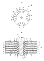
図1aは本発明のモータ用ロータの実施の形態1の平面図であり、図1bは図1aのb−b矢視図である。
(
FIG. 1a is a plan view of a first embodiment of a motor rotor of the present invention, and FIG. 1b is a view taken along the line bb in FIG. 1a.
図1で示すモータ用ロータ20はIPMモータ用のロータである。その製造方法は、複数の電磁鋼板1を積層するに当たり、対応するスロット用開口11を位置合わせしながら電磁鋼板1を積層し、全体をかしめてロータコア10を形成する。なお、使用する電磁鋼板としては、珪素鋼板やそのほかの軟磁性材料から形成された鋼板が挙げられる。
A
各電磁鋼板1は、その表面に絶縁被膜を有した広幅な電磁鋼板を図示する円盤状に打抜いて形成され、円盤状の電磁鋼板1においても、略Vの字状の2つの磁石用スロット開口11を一組としてこれを磁極数に応じた組数だけ打ち抜き加工にて形成する。さらに、形成された磁石用スロット開口11の端部を折り曲げ加工することにより、折り曲げ加工点1aから屈曲する所定長さの端部1bを形成する。なお、電磁鋼板1はその上下2つの積層面に絶縁被膜3を有していてもよいし、いずれか一方の積層面にのみ絶縁被膜3を有していてもよいが、後者の場合には、電磁鋼板1を積層した際に各電磁鋼板1の間に絶縁被膜3が存在するようにして積層する。
Each
電磁鋼板1における永久磁石と接する端部を折り曲げ加工することから、特許文献1で開示するせん断加工する場合のように電磁鋼板の端部にバリが生じることはない。
Since the end portion of the
すべての電磁鋼板1の折り曲げ加工点1aの位置や端部1bの長さはいずれも同じになるように加工し、電磁鋼板1を積層した際に、図1bで示すようにそれぞれの屈曲した端部1が同一方向を向いて隙間なく積層されるようにする。
When the
さらに、形成される磁石用スロット11の寸法は永久磁石2の寸法よりも大きめに形成されており、永久磁石2を磁石用スロット11内に配設した後、スロット11内にできた隙間に固定用樹脂4を充填し、これが硬化することによってスロット11内に永久磁石2が固定されてなるモータ用ロータ20が製造される。
Further, the size of the
磁石用スロット11に配設される永久磁石2としては、希土類磁石やフェライト磁石、アルニコ磁石等を適用することができ、この希土類磁石としては、ネオジムに鉄とボロンを加えた3成分系のネオジム磁石、サマリウムとコバルトとの2成分系の合金からなるサマリウムコバルト磁石などを挙げることができる。
As the
図1bにおいて、磁石用スロット11を形成する積層姿勢の各電磁鋼板1の一部と永久磁石2が接触しているが、各電磁鋼板1の端部1bの隅角1cが永久磁石2との接触部となっている。
In FIG. 1 b, the
そして、この接触部1cと永久磁石2は線接触する(図の奥行き方向に線接触する)ことから、従来構造のロータのように双方が面接触する場合に比して接触面積を大幅に低減でき、電磁鋼板1と永久磁石2の間の電気抵抗を高め、双方の間の通電抑制を図ることができる。
Since the
しかも、接触部1cは隅角の表面に存在している絶縁被膜3から形成され、この絶縁被膜3と永久磁石2が直接接触することから、永久磁石2と電磁鋼板1との電気的な通電は完全に解消される。その結果、従来構造のモータ用ロータの場合における面接触した電磁鋼板の端面と永久磁石との間に形成される大きな渦電流により、渦電流損失が増加するといった課題は効果的に解消されることになる。
In addition, the
製造されたモータ用ロータ20を用い、不図示のコイルをティース周りに具備する環状のステータの内部にモータ用ロータ20を配設することにより、不図示のIPMモータが形成される。
An IPM motor (not shown) is formed by using the manufactured
(モータ用ロータとその製造方法の実施の形態2)
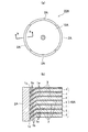
図2aは本発明のモータ用ロータの実施の形態2の平面図であり、図2bは図2aのb−b矢視図である。
(
2a is a plan view of a second embodiment of the motor rotor of the present invention, and FIG. 2b is a view taken along the line bb in FIG. 2a.
図2で示すモータ用ロータ20AはSPMモータ用のロータであり、その製造方法は、電磁鋼板1を積層し、全体をかしめてロータコア10Aを形成した後に、その側面外周に断面が円弧状の4つの永久磁石2Aを接着してモータ用ロータ20Aを製造する。
The
ここで、各電磁鋼板1は、実施の形態1と同様にその表面に絶縁被膜を有した広幅な電磁鋼板を図示する円盤状に打抜いて形成され、さらに、その外周の端部を折り曲げ加工することにより、折り曲げ加工点1aから屈曲する所定長さの端部1bを形成する。
Here, each
この実施の形態においても、接触部1cと永久磁石2は線接触し、さらに、接触部1cは隅角の表面に存在する絶縁被膜3から形成され、この絶縁被膜3と永久磁石2が直接接触することから、永久磁石2と電磁鋼板1との電気的な通電は完全に解消されることになる。
Also in this embodiment, the
以上、本発明の実施の形態を図面を用いて詳述してきたが、具体的な構成はこの実施形態に限定されるものではなく、本発明の要旨を逸脱しない範囲における設計変更等があっても、それらは本発明に含まれるものである。 The embodiment of the present invention has been described in detail with reference to the drawings. However, the specific configuration is not limited to this embodiment, and there are design changes and the like without departing from the gist of the present invention. They are also included in the present invention.
1…電磁鋼板、1a…折り曲げ加工点、1b…端部(永久磁石と接する端部)、1c…接触部(接触線、隅角)、2,2A…永久磁石、3…絶縁被膜、4…固定用樹脂、10,10A…ロータコア、11…磁石用スロット(磁石用スロット開口)、20,20A…モータ用ロータ
DESCRIPTION OF
Claims (6)
少なくとも一方の積層面に絶縁被膜を有したそれぞれの電磁鋼板の永久磁石と接する端部を同一方向に折り曲げ加工し、積層してロータコアを製造し、永久磁石を配設してロータコアに固定するモータ用ロータの製造方法。 A method for producing a rotor for a motor comprising a rotor core in which electromagnetic steel sheets are laminated and a permanent magnet,
Motors in which end portions in contact with permanent magnets of each electromagnetic steel sheet having an insulating coating on at least one laminated surface are bent in the same direction, laminated to produce a rotor core, and permanent magnets are disposed and fixed to the rotor core Of manufacturing a rotor for an automobile.
少なくとも一方の積層面に絶縁被膜を有したそれぞれの電磁鋼板の永久磁石と接する端部が同一方向に折り曲げ加工され、電磁鋼板が積層されてロータコアが形成されており、ロータコアに永久磁石が固定されてなるモータ用ロータ。 A rotor for a motor comprising a rotor core formed by laminating electromagnetic steel sheets and a permanent magnet,
Ends in contact with the permanent magnet of each electromagnetic steel sheet having an insulating coating on at least one laminated surface are bent in the same direction, and the electromagnetic steel sheets are laminated to form a rotor core, and the permanent magnet is fixed to the rotor core. Motor rotor.
Priority Applications (1)
| Application Number | Priority Date | Filing Date | Title |
|---|---|---|---|
| JP2011239254A JP2013099089A (en) | 2011-10-31 | 2011-10-31 | Rotor for motor and method of manufacturing the same |
Applications Claiming Priority (1)
| Application Number | Priority Date | Filing Date | Title |
|---|---|---|---|
| JP2011239254A JP2013099089A (en) | 2011-10-31 | 2011-10-31 | Rotor for motor and method of manufacturing the same |
Publications (1)
| Publication Number | Publication Date |
|---|---|
| JP2013099089A true JP2013099089A (en) | 2013-05-20 |
Family
ID=48620477
Family Applications (1)
| Application Number | Title | Priority Date | Filing Date |
|---|---|---|---|
| JP2011239254A Pending JP2013099089A (en) | 2011-10-31 | 2011-10-31 | Rotor for motor and method of manufacturing the same |
Country Status (1)
| Country | Link |
|---|---|
| JP (1) | JP2013099089A (en) |
Cited By (2)
| Publication number | Priority date | Publication date | Assignee | Title |
|---|---|---|---|---|
| CN104065189A (en) * | 2014-06-06 | 2014-09-24 | 杭州微光电子股份有限公司 | Tile-shaped magnetic steel magnetism division fixing frame used for permanent magnet motor |
| WO2022116533A1 (en) * | 2020-12-04 | 2022-06-09 | 上海威迈斯新能源有限公司 | Rotor and motor |
Citations (2)
| Publication number | Priority date | Publication date | Assignee | Title |
|---|---|---|---|---|
| JP2007074776A (en) * | 2005-09-05 | 2007-03-22 | Kokusan Denki Co Ltd | Rotating electric machine |
| JP2011172441A (en) * | 2010-02-22 | 2011-09-01 | Toyota Boshoku Corp | Motor core and assembling method thereof |
-
2011
- 2011-10-31 JP JP2011239254A patent/JP2013099089A/en active Pending
Patent Citations (2)
| Publication number | Priority date | Publication date | Assignee | Title |
|---|---|---|---|---|
| JP2007074776A (en) * | 2005-09-05 | 2007-03-22 | Kokusan Denki Co Ltd | Rotating electric machine |
| JP2011172441A (en) * | 2010-02-22 | 2011-09-01 | Toyota Boshoku Corp | Motor core and assembling method thereof |
Cited By (3)
| Publication number | Priority date | Publication date | Assignee | Title |
|---|---|---|---|---|
| CN104065189A (en) * | 2014-06-06 | 2014-09-24 | 杭州微光电子股份有限公司 | Tile-shaped magnetic steel magnetism division fixing frame used for permanent magnet motor |
| CN104065189B (en) * | 2014-06-06 | 2016-07-06 | 杭州微光电子股份有限公司 | A kind of tile-shaped magnet steel for magneto divides magnetically fixed frame |
| WO2022116533A1 (en) * | 2020-12-04 | 2022-06-09 | 上海威迈斯新能源有限公司 | Rotor and motor |
Similar Documents
| Publication | Publication Date | Title |
|---|---|---|
| CN103597714B (en) | The manufacture method of rotor for dynamo-electric machine, electric rotating machine and rotor for dynamo-electric machine | |
| CN109075681B (en) | Motor and air conditioner | |
| CN108370178B (en) | Axial gap type rotating electric machine and method for manufacturing same | |
| EP1964242B1 (en) | Rotor assembly for use in line start permanent magnet synchronous motor | |
| US20140084734A1 (en) | Rotating Electrical Machine, Method for Manufacturing Magnetic Pole Piece | |
| WO2014102950A1 (en) | Rotating electrical machine | |
| JP2009284578A (en) | Axial gap motor and fan apparatus using the same | |
| JP6545387B2 (en) | Conscious pole rotor, motor and air conditioner | |
| JP2014045634A (en) | Rotor and rotary electric machine including the same | |
| JPWO2012007984A1 (en) | Amorphous core, electromagnetic member and rotating electric machine using the same, and manufacturing method thereof | |
| CN111953097A (en) | Rotating electrical machine | |
| JP2009038904A (en) | Stator | |
| CN108496293B (en) | Electrical sheet with printed connecting sheet | |
| JP2009055750A (en) | Claw pole type pm motor and its manufacturing method | |
| JP2010183692A (en) | Magnet for motor, rotor for IPM motor, and IPM motor | |
| US10374474B2 (en) | Permanent magnet motor | |
| JP2013099089A (en) | Rotor for motor and method of manufacturing the same | |
| CN106063085B (en) | Rotor | |
| JP5692105B2 (en) | Manufacturing method of rotor for IPM motor | |
| JP2022545016A (en) | Building Synchronous Reluctance Machines Using Additive Manufacturing | |
| JPWO2018042634A1 (en) | Rotor, rotating electrical machine, and method of manufacturing rotor | |
| JP7038527B2 (en) | Manufacturing method of magnetic wedge for rotary electric machine, magnetic wedge for rotary electric machine, and rotary electric machine | |
| JP2000245124A (en) | Smooth core armature wound motor | |
| JP2013207920A (en) | Permanent magnet type rotary electrical machine | |
| JP2018042381A (en) | Rotary electric machine rotor |
Legal Events
| Date | Code | Title | Description |
|---|---|---|---|
| A621 | Written request for application examination |
Free format text: JAPANESE INTERMEDIATE CODE: A621 Effective date: 20140116 |
|
| A977 | Report on retrieval |
Free format text: JAPANESE INTERMEDIATE CODE: A971007 Effective date: 20141015 |
|
| A131 | Notification of reasons for refusal |
Free format text: JAPANESE INTERMEDIATE CODE: A131 Effective date: 20141118 |
|
| A02 | Decision of refusal |
Free format text: JAPANESE INTERMEDIATE CODE: A02 Effective date: 20150310 |