JP2017135515A5 - - Google Patents
Download PDFInfo
- Publication number
- JP2017135515A5 JP2017135515A5 JP2016012791A JP2016012791A JP2017135515A5 JP 2017135515 A5 JP2017135515 A5 JP 2017135515A5 JP 2016012791 A JP2016012791 A JP 2016012791A JP 2016012791 A JP2016012791 A JP 2016012791A JP 2017135515 A5 JP2017135515 A5 JP 2017135515A5
- Authority
- JP
- Japan
- Prior art keywords
- exposure time
- background
- angular velocity
- imaging
- amount
- Prior art date
- Legal status (The legal status is an assumption and is not a legal conclusion. Google has not performed a legal analysis and makes no representation as to the accuracy of the status listed.)
- Granted
Links
- 238000003384 imaging method Methods 0.000 claims description 18
- 230000003287 optical Effects 0.000 claims description 12
- 238000001514 detection method Methods 0.000 claims description 5
- 238000004091 panning Methods 0.000 claims description 5
- 230000003247 decreasing Effects 0.000 claims 1
- 238000000034 method Methods 0.000 claims 1
Images
Description
上記目的を達成するために、本発明の撮像装置は、撮像光学系を介して入射した被写体像を撮影する撮像手段と、流し撮り撮影における背景の流し量を設定する設定手段と、流し撮り撮影において、前記設定手段により設定された前記背景の流し量となるように、前記背景の流し量と、振れの角速度を検出する検出手段にて検出された角速度と、前記撮像光学系の焦点距離とから、露光時間を演算する演算手段と、を有し、前記設定手段は、予め設定された複数の背景の流し量のレベルのいずれかを選択することにより、前記背景の流し量を設定し、前記演算手段は、前記背景の流し量が増加すると前記露光時間を伸ばし、前記角速度が増加すると前記露光時間を短くし、前記焦点距離が短くなると前記露光時間を短くするように演算する。 In order to achieve the above object, an imaging apparatus according to the present invention includes an imaging unit that captures a subject image incident through an imaging optical system, a setting unit that sets a background sink amount in panning shooting, and a panning shooting. The background flow amount set by the setting means, the background flow amount, the angular velocity detected by the detection means for detecting the angular velocity of shake, and the focal length of the imaging optical system, from possess a calculating means for calculating a exposure time, and the setting means, by selecting one of the flow amount of the levels of a plurality of background that is set in advance to set the flow amount of the background The computing means computes to extend the exposure time when the background flow amount increases, shorten the exposure time when the angular velocity increases, and shorten the exposure time when the focal length is shortened .
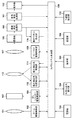
振れ補正系駆動部111は、振れ補正部112の駆動用のボイスコイル型モータであり、振れ補正系駆動部111によって駆動されることにより、振れ補正部112が光軸と垂直な方向に移動される。振れ補正系位置検出部113は、磁石とそれに対抗する位置に供えられたホールセンサとからなり、振れ補正部112の光軸と垂直な方向への移動量を検出し、その検出結果をA/D変換器114を介して、減算器108に供給する。振れ補正部112は、例えばシフトレンズであり、光軸と垂直な方向に移動されることにより光軸をシフトする、光学的に振れ補正可能な補正系である。または、撮像部159を光軸と垂直な方向に移動させても良い。その結果、装置の振れ等により生じる撮像面上の被写体の移動が補正された像が、撮像部159に結像される。
The shake correction
Claims (6)
流し撮り撮影における背景の流し量を設定する設定手段と、
流し撮り撮影において、前記設定手段により設定された前記背景の流し量となるように、前記背景の流し量と、振れの角速度を検出する検出手段にて検出された角速度と、前記撮像光学系の焦点距離とから、露光時間を演算する演算手段と、を有し、
前記設定手段は、予め設定された複数の背景の流し量のレベルのいずれかを選択することにより、前記背景の流し量を設定し、
前記演算手段は、前記背景の流し量が増加すると前記露光時間を伸ばし、前記角速度が増加すると前記露光時間を短くし、前記焦点距離が短くなると前記露光時間を短くするように演算することを特徴とする撮像装置。 Imaging means for photographing a subject image incident through the imaging optical system;
A setting means for setting a background sink amount in panning shooting;
In the panning shooting, the background flow amount, the angular velocity detected by the detecting means for detecting the angular velocity of the shake, and the imaging optical system so as to be the background flow amount set by the setting device. a and a focal length, and calculating means for calculating the exposure time, and
The setting means sets the background sink amount by selecting one of a plurality of preset background sink levels,
The calculating means calculates the exposure time to be increased when the background sink amount is increased, the exposure time is shortened when the angular velocity is increased, and the exposure time is decreased when the focal length is shortened. An imaging device.
前記角速度、及び、前記動きベクトルの少なくともいずれかに基づいて、振れ補正量を求め、振れ補正手段を駆動することにより振れを補正する補正手段と、を更に有し、
前記演算手段は、前記露光時間と前記振れ補正量との積が、前記振れ補正手段の駆動範囲内に収まらない場合に、前記積が、前記振れ補正手段の駆動範囲内に収まるように、前記露光時間を変更することを特徴とする請求項1または2に記載の撮像装置。 Motion vector detection means for obtaining and outputting a motion vector from the difference between frames of the image output from the imaging means;
Correction means for obtaining a shake correction amount based on at least one of the angular velocity and the motion vector and correcting shake by driving the shake correction means ;
The calculation means is configured so that when the product of the exposure time and the shake correction amount does not fall within the drive range of the shake correction means, the product falls within the drive range of the shake correction means. the imaging apparatus according to claim 1 or 2, characterized in that to change the exposure time.
設定手段が、背景の流し量を設定する設定工程と、
演算手段が、前記設定工程で設定された前記背景の流し量となるように、前記背景の流し量と、振れの角速度を検出する検出手段にて検出された角速度と、前記撮像光学系の焦点距離とから、露光時間を取得演算する演算工程と、を有し、
前記設定工程では、予め設定された複数の背景の流し量のレベルのいずれかを選択することにより、前記背景の流し量を設定し、
前記演算工程では、前記背景の流し量が増加すると前記露光時間を伸ばし、前記角速度が増加すると前記露光時間を短くし、前記焦点距離が短くなると前記露光時間を短くするように演算することを特徴とする制御方法。 A method for controlling an imaging apparatus during panning shooting by an imaging unit that images a subject image incident through an imaging optical system,
A setting step in which the setting means sets a background sink amount;
The calculation means has the background flow amount set in the setting step, the background flow amount, the angular velocity detected by the detection means for detecting the angular velocity of shake, and the focus of the imaging optical system. a distance from the, a calculation step of acquiring calculating the exposure time, and
In the setting step, by selecting one of a plurality of preset background flow levels, the background flow amount is set,
In the calculating step, the exposure time is extended when the background flow amount increases, the exposure time is shortened when the angular velocity increases, and the exposure time is shortened when the focal length is shortened. Control method.
Priority Applications (3)
| Application Number | Priority Date | Filing Date | Title |
|---|---|---|---|
| JP2016012791A JP6738151B2 (en) | 2016-01-26 | 2016-01-26 | Imaging device and control method thereof |
| US15/414,732 US10205885B2 (en) | 2016-01-26 | 2017-01-25 | Image capturing apparatus for controlling shutter speed during panning shooting and method for controlling the same |
| US15/976,211 US10623652B2 (en) | 2016-01-26 | 2018-05-10 | Image capturing apparatus and method for image stabilization and control using motion vectors |
Applications Claiming Priority (1)
| Application Number | Priority Date | Filing Date | Title |
|---|---|---|---|
| JP2016012791A JP6738151B2 (en) | 2016-01-26 | 2016-01-26 | Imaging device and control method thereof |
Publications (3)
| Publication Number | Publication Date |
|---|---|
| JP2017135515A JP2017135515A (en) | 2017-08-03 |
| JP2017135515A5 true JP2017135515A5 (en) | 2019-02-28 |
| JP6738151B2 JP6738151B2 (en) | 2020-08-12 |
Family
ID=59504500
Family Applications (1)
| Application Number | Title | Priority Date | Filing Date |
|---|---|---|---|
| JP2016012791A Active JP6738151B2 (en) | 2016-01-26 | 2016-01-26 | Imaging device and control method thereof |
Country Status (1)
| Country | Link |
|---|---|
| JP (1) | JP6738151B2 (en) |
Families Citing this family (2)
| Publication number | Priority date | Publication date | Assignee | Title |
|---|---|---|---|---|
| JP7013199B2 (en) * | 2017-10-23 | 2022-01-31 | キヤノン株式会社 | Image pickup device and its control method |
| KR101991094B1 (en) * | 2018-04-23 | 2019-06-19 | 주식회사 울프슨랩 | Method for distance measurement, Apparatus for distance measurement, Computer program for the same, and Recording medium storing computer program for the same |
Family Cites Families (5)
| Publication number | Priority date | Publication date | Assignee | Title |
|---|---|---|---|---|
| US9432575B2 (en) * | 2013-06-28 | 2016-08-30 | Canon Kabushiki Kaisha | Image processing apparatus |
| JP6338424B2 (en) * | 2014-04-03 | 2018-06-06 | キヤノン株式会社 | Image processing apparatus, control method therefor, imaging apparatus, and program |
| JP2015219462A (en) * | 2014-05-20 | 2015-12-07 | オリンパス株式会社 | Imaging device, control method of imaging device and program |
| JP6360721B2 (en) * | 2014-05-20 | 2018-07-18 | オリンパス株式会社 | IMAGING DEVICE, IMAGING DEVICE CONTROL METHOD, AND PROGRAM |
| JP2016009998A (en) * | 2014-06-24 | 2016-01-18 | キヤノン株式会社 | Imaging apparatus, imaging method and program |
-
2016
- 2016-01-26 JP JP2016012791A patent/JP6738151B2/en active Active
Similar Documents
| Publication | Publication Date | Title |
|---|---|---|
| JP2015152888A5 (en) | Image processing apparatus and control method thereof | |
| JP2015200847A5 (en) | ||
| JP2016109758A5 (en) | ||
| JP2014182209A5 (en) | Imaging apparatus, image processing apparatus, and control method thereof | |
| JP2015185925A5 (en) | ||
| JP2017142344A5 (en) | ||
| US20150195461A1 (en) | Apparatus and method for image correction | |
| JP2016118701A5 (en) | ||
| JP2014128014A5 (en) | IMAGING DEVICE, IMAGE PROCESSING DEVICE AND ITS CONTROL METHOD, PROGRAM, AND STORAGE MEDIUM | |
| JP2017134177A5 (en) | ||
| JP2019078843A5 (en) | ||
| JP2016167798A5 (en) | Imaging apparatus, control method, control program, and storage medium | |
| JP2018146663A5 (en) | ||
| JP2019080137A5 (en) | ||
| JP2017090711A5 (en) | ||
| JP2017187693A5 (en) | ||
| JP2015227995A5 (en) | ||
| JP2019078843A (en) | Image blur correction apparatus, control method thereof, and imaging apparatus | |
| JP2016136242A5 (en) | Control device and lens device | |
| JP2016116008A5 (en) | ||
| JP2014055999A5 (en) | ||
| JP2008177785A5 (en) | ||
| JP2016170285A5 (en) | ||
| JP2016018116A5 (en) | ||
| JP2011164228A5 (en) | Optical device and control method thereof |