JP2017134992A - Lighting device, pattern lighting device and system - Google Patents

Lighting device, pattern lighting device and system Download PDF

Info

Publication number
JP2017134992A
JP2017134992A JP2016013726A JP2016013726A JP2017134992A JP 2017134992 A JP2017134992 A JP 2017134992A JP 2016013726 A JP2016013726 A JP 2016013726A JP 2016013726 A JP2016013726 A JP 2016013726A JP 2017134992 A JP2017134992 A JP 2017134992A
Authority
JP
Japan
Prior art keywords
light
unit
emitted
pattern irradiation
lighting device
Prior art date
Legal status (The legal status is an assumption and is not a legal conclusion. Google has not performed a legal analysis and makes no representation as to the accuracy of the status listed.)
Granted
Application number
JP2016013726A
Other languages
Japanese (ja)
Other versions
JP6024841B1 (en
Inventor
高橋 達也
Tatsuya Takahashi
達也 高橋
Current Assignee (The listed assignees may be inaccurate. Google has not performed a legal analysis and makes no representation or warranty as to the accuracy of the list.)
Ricoh Co Ltd
Original Assignee
Ricoh Co Ltd
Priority date (The priority date is an assumption and is not a legal conclusion. Google has not performed a legal analysis and makes no representation as to the accuracy of the date listed.)
Filing date
Publication date
Application filed by Ricoh Co Ltd filed Critical Ricoh Co Ltd
Priority to JP2016013726A priority Critical patent/JP6024841B1/en
Application granted granted Critical
Publication of JP6024841B1 publication Critical patent/JP6024841B1/en
Priority to EP17151055.5A priority patent/EP3199911B1/en
Priority to US15/407,468 priority patent/US20170210006A1/en
Publication of JP2017134992A publication Critical patent/JP2017134992A/en
Active legal-status Critical Current
Anticipated expiration legal-status Critical

Links

Images

Classifications

    • BPERFORMING OPERATIONS; TRANSPORTING
    • B25HAND TOOLS; PORTABLE POWER-DRIVEN TOOLS; MANIPULATORS
    • B25JMANIPULATORS; CHAMBERS PROVIDED WITH MANIPULATION DEVICES
    • B25J9/00Programme-controlled manipulators
    • B25J9/16Programme controls
    • B25J9/1612Programme controls characterised by the hand, wrist, grip control
    • BPERFORMING OPERATIONS; TRANSPORTING
    • B25HAND TOOLS; PORTABLE POWER-DRIVEN TOOLS; MANIPULATORS
    • B25JMANIPULATORS; CHAMBERS PROVIDED WITH MANIPULATION DEVICES
    • B25J9/00Programme-controlled manipulators
    • B25J9/16Programme controls
    • B25J9/1694Programme controls characterised by use of sensors other than normal servo-feedback from position, speed or acceleration sensors, perception control, multi-sensor controlled systems, sensor fusion
    • B25J9/1697Vision controlled systems
    • GPHYSICS
    • G01MEASURING; TESTING
    • G01BMEASURING LENGTH, THICKNESS OR SIMILAR LINEAR DIMENSIONS; MEASURING ANGLES; MEASURING AREAS; MEASURING IRREGULARITIES OF SURFACES OR CONTOURS
    • G01B11/00Measuring arrangements characterised by the use of optical techniques
    • G01B11/24Measuring arrangements characterised by the use of optical techniques for measuring contours or curvatures
    • G01B11/25Measuring arrangements characterised by the use of optical techniques for measuring contours or curvatures by projecting a pattern, e.g. one or more lines, moiré fringes on the object
    • G01B11/2545Measuring arrangements characterised by the use of optical techniques for measuring contours or curvatures by projecting a pattern, e.g. one or more lines, moiré fringes on the object with one projection direction and several detection directions, e.g. stereo
    • GPHYSICS
    • G01MEASURING; TESTING
    • G01CMEASURING DISTANCES, LEVELS OR BEARINGS; SURVEYING; NAVIGATION; GYROSCOPIC INSTRUMENTS; PHOTOGRAMMETRY OR VIDEOGRAMMETRY
    • G01C3/00Measuring distances in line of sight; Optical rangefinders
    • G01C3/02Details
    • G01C3/06Use of electric means to obtain final indication
    • G01C3/08Use of electric radiation detectors
    • GPHYSICS
    • G02OPTICS
    • G02BOPTICAL ELEMENTS, SYSTEMS OR APPARATUS
    • G02B27/00Optical systems or apparatus not provided for by any of the groups G02B1/00 - G02B26/00, G02B30/00
    • G02B27/30Collimators
    • GPHYSICS
    • G02OPTICS
    • G02BOPTICAL ELEMENTS, SYSTEMS OR APPARATUS
    • G02B5/00Optical elements other than lenses
    • G02B5/02Diffusing elements; Afocal elements
    • G02B5/0273Diffusing elements; Afocal elements characterized by the use
    • G02B5/0278Diffusing elements; Afocal elements characterized by the use used in transmission
    • GPHYSICS
    • G02OPTICS
    • G02BOPTICAL ELEMENTS, SYSTEMS OR APPARATUS
    • G02B5/00Optical elements other than lenses
    • G02B5/02Diffusing elements; Afocal elements
    • G02B5/0273Diffusing elements; Afocal elements characterized by the use
    • G02B5/0284Diffusing elements; Afocal elements characterized by the use used in reflection
    • GPHYSICS
    • G03PHOTOGRAPHY; CINEMATOGRAPHY; ANALOGOUS TECHNIQUES USING WAVES OTHER THAN OPTICAL WAVES; ELECTROGRAPHY; HOLOGRAPHY
    • G03BAPPARATUS OR ARRANGEMENTS FOR TAKING PHOTOGRAPHS OR FOR PROJECTING OR VIEWING THEM; APPARATUS OR ARRANGEMENTS EMPLOYING ANALOGOUS TECHNIQUES USING WAVES OTHER THAN OPTICAL WAVES; ACCESSORIES THEREFOR
    • G03B21/00Projectors or projection-type viewers; Accessories therefor
    • G03B21/14Details
    • G03B21/20Lamp housings
    • G03B21/208Homogenising, shaping of the illumination light
    • BPERFORMING OPERATIONS; TRANSPORTING
    • B25HAND TOOLS; PORTABLE POWER-DRIVEN TOOLS; MANIPULATORS
    • B25JMANIPULATORS; CHAMBERS PROVIDED WITH MANIPULATION DEVICES
    • B25J13/00Controls for manipulators
    • B25J13/08Controls for manipulators by means of sensing devices, e.g. viewing or touching devices
    • GPHYSICS
    • G05CONTROLLING; REGULATING
    • G05BCONTROL OR REGULATING SYSTEMS IN GENERAL; FUNCTIONAL ELEMENTS OF SUCH SYSTEMS; MONITORING OR TESTING ARRANGEMENTS FOR SUCH SYSTEMS OR ELEMENTS
    • G05B2219/00Program-control systems
    • G05B2219/30Nc systems
    • G05B2219/40Robotics, robotics mapping to robotics vision
    • G05B2219/40053Pick 3-D object from pile of objects
    • GPHYSICS
    • G05CONTROLLING; REGULATING
    • G05BCONTROL OR REGULATING SYSTEMS IN GENERAL; FUNCTIONAL ELEMENTS OF SUCH SYSTEMS; MONITORING OR TESTING ARRANGEMENTS FOR SUCH SYSTEMS OR ELEMENTS
    • G05B2219/00Program-control systems
    • G05B2219/30Nc systems
    • G05B2219/40Robotics, robotics mapping to robotics vision
    • G05B2219/40564Recognize shape, contour of object, extract position and orientation
    • GPHYSICS
    • G05CONTROLLING; REGULATING
    • G05BCONTROL OR REGULATING SYSTEMS IN GENERAL; FUNCTIONAL ELEMENTS OF SUCH SYSTEMS; MONITORING OR TESTING ARRANGEMENTS FOR SUCH SYSTEMS OR ELEMENTS
    • G05B2219/00Program-control systems
    • G05B2219/30Nc systems
    • G05B2219/40Robotics, robotics mapping to robotics vision
    • G05B2219/40604Two camera, global vision camera, end effector neighbourhood vision camera

Abstract

PROBLEM TO BE SOLVED: To provide a lighting device that evenly irradiates a projection face with light and has a transmissive diffusion plate 33b to reduce irradiation density to an irradiation optical system 36.SOLUTION: The lighting device 20 includes: a light-emitting part 31 for emitting light; a condensation part 32 for condensing light emitted from the light-emitting part 31; a first diffusion part 33a for diffusing light condensed by the condensation part 32; a homogenizing optical system 34 for emitting light after homogenizing the illuminance distribution thereof; and a second diffusion part 33a for diffusing light emitted from the homogenizing optical system 34.SELECTED DRAWING: Figure 2

Description

本発明は、照明装置、パターン照射装置およびシステムに関する。   The present invention relates to an illumination device, a pattern irradiation device, and a system.

従来より、トレイに積載された対象物(ワーク)をロボットを用いてハンドリングして、対象物を次工程の装置へと搬送したり、対象物を用いて製品を組み立てたりするシステムが知られている。このようなシステムでは、三次元測定装置によりトレイ上の対象物の距離を測定し、測定結果に基づき対象物の位置および姿勢を認識してハンドリングをする。また、このようなシステムでは、パターン照射装置によりトレイ上の対象物に所定のパターンの光を照射して、三次元測定装置による距離測定の精度を向上させる(例えば、特許文献1、2)。   Conventionally, a system for handling an object (work) loaded on a tray using a robot and transporting the object to an apparatus in the next process or assembling a product using the object is known. Yes. In such a system, the distance of the object on the tray is measured by a three-dimensional measuring device, and the position and orientation of the object are recognized based on the measurement result for handling. Moreover, in such a system, the pattern irradiation apparatus irradiates the object on the tray with a predetermined pattern of light to improve the accuracy of distance measurement by the three-dimensional measurement apparatus (for example, Patent Documents 1 and 2).

ところで、距離測定の精度を向上させるには、投射面に均質で強度の高い光を照射する必要がある。単に光源の光出力を向上させるのみでは、照射密度も併せて向上してしまうために、照射光学系を構成するレンズ等の光学部材の劣化を生じるおそれがある。   By the way, in order to improve the accuracy of distance measurement, it is necessary to irradiate the projection surface with light that is uniform and high in intensity. If the light output of the light source is simply improved, the irradiation density is also improved. Therefore, there is a possibility that the optical member such as a lens constituting the irradiation optical system is deteriorated.

本発明は、上記に鑑みてなされたものであって、投射面に光が均一に照射されるとともに、照射光学系への照射密度が低減される照明装置を提供することを目的とする。   This invention is made in view of the above, Comprising: It aims at providing the illuminating device by which light is uniformly irradiated to a projection surface and the irradiation density to an irradiation optical system is reduced.

上述した課題を解決し、目的を達成するために、本発明に係る照明装置は、光を出射する発光部と、前記発光部から出射された光を集光する集光部と、前記集光部により集光された光を拡散させる第1拡散部と、照度分布を均一化して出射する均一化光学系と、前記均一化光学系から出射した光を拡散する第2拡散部と、を備える。   In order to solve the above-described problems and achieve the object, an illumination device according to the present invention includes a light emitting unit that emits light, a light collecting unit that collects light emitted from the light emitting unit, and the light collecting unit. A first diffusion unit that diffuses the light collected by the unit, a uniformizing optical system that emits light with uniform illuminance distribution, and a second diffusion unit that diffuses light emitted from the uniformizing optical system. .

本発明によれば、投射面に光が均一に照射されるとともに、照射光学系への照射密度が低減されて光学部品の劣化を抑制することができる。   According to the present invention, it is possible to uniformly irradiate the projection surface with light, reduce the irradiation density to the irradiation optical system, and suppress deterioration of the optical component.

第1実施形態に係るハンドリングシステムの構成の一例を示す図である。It is a figure which shows an example of a structure of the handling system which concerns on 1st Embodiment. 第1実施形態に係るパターン照射装置の構成の一例を示す図である。It is a figure which shows an example of a structure of the pattern irradiation apparatus which concerns on 1st Embodiment. ライトトンネルでの光路の一例を示す図である。It is a figure which shows an example of the optical path in a light tunnel. 第1実施形態に係るパターン照射装置の構成の一部分の斜視図である。It is a perspective view of a part of composition of a pattern irradiation apparatus concerning a 1st embodiment. 第2実施形態に係るパターン照射装置の構成の一例を示す図である。It is a figure which shows an example of a structure of the pattern irradiation apparatus which concerns on 2nd Embodiment. 反射拡散板での光路の一例を示す図である。It is a figure which shows an example of the optical path in a reflective diffusing plate. 反射拡散板が脱落した場合の光路の一例を示す図である。It is a figure which shows an example of the optical path when a reflective diffusing plate falls off. 第3実施形態に係るパターン照射装置の構成の一例を示す図である。It is a figure which shows an example of a structure of the pattern irradiation apparatus which concerns on 3rd Embodiment. テーパライトトンネルでの光路の一例を示す図である。It is a figure which shows an example of the optical path in a taper light tunnel. 第4実施形態に係るパターン照射装置の構成の一例を示す図である。It is a figure which shows an example of a structure of the pattern irradiation apparatus which concerns on 4th Embodiment. 第4実施形態に係る第1のミラー群およびレンズ等の配置の一例を示す図である。It is a figure which shows an example of arrangement | positioning of the 1st mirror group and lens etc. which concern on 4th Embodiment. 図12の(a)は、単板ミラーを用いた場合の光路の一例を示す図であり、図12の(b)は、第1のミラー群を用いた場合の光路の一例を示す図である。12A is a diagram illustrating an example of an optical path when a single plate mirror is used, and FIG. 12B is a diagram illustrating an example of an optical path when the first mirror group is used. is there. 第5実施形態に係るパターン照射装置の構成の一例を示す図である。It is a figure which shows an example of a structure of the pattern irradiation apparatus which concerns on 5th Embodiment. 第5実施形態に係る第2のミラー群およびシリンドリカルレンズ等の配置の一例を示す図である。It is a figure which shows an example of arrangement | positioning of the 2nd mirror group which concerns on 5th Embodiment, a cylindrical lens, etc. FIG. 第6実施形態に係るパターン照射装置の構成の一例を示す図である。It is a figure which shows an example of a structure of the pattern irradiation apparatus which concerns on 6th Embodiment. 第6実施形態に係る第3のミラー群等の配置の一例を示す図である。It is a figure which shows an example of arrangement | positioning of the 3rd mirror group etc. which concern on 6th Embodiment. 第7実施形態に係るパターン照射装置の構成の一例を示す図である。It is a figure which shows an example of a structure of the pattern irradiation apparatus which concerns on 7th Embodiment. 第8実施形態に係るパターン照射装置の構成の一例を示す図である。It is a figure which shows an example of a structure of the pattern irradiation apparatus which concerns on 8th Embodiment. 可動蛍光部および第1の駆動部の一例を示す図である。It is a figure which shows an example of a movable fluorescence part and a 1st drive part. 第9実施形態に係るパターン照射装置の構成の一例を示す図である。It is a figure which shows an example of a structure of the pattern irradiation apparatus which concerns on 9th Embodiment. 反射蛍光部を側面側から見た図である。It is the figure which looked at the reflective fluorescence part from the side surface side. 第10実施形態に係るパターン照射装置の構成の一例を示す図である。It is a figure which shows an example of a structure of the pattern irradiation apparatus which concerns on 10th Embodiment. 第11実施形態に係るパターン照射装置の構成の一例を示す図である。It is a figure which shows an example of a structure of the pattern irradiation apparatus which concerns on 11th Embodiment.

以下に添付図面を参照して、本発明の実施形態に係るハンドリングシステム10を詳細に説明する。   Hereinafter, a handling system 10 according to an embodiment of the present invention will be described in detail with reference to the accompanying drawings.

(第1実施形態)
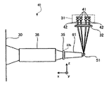
図1は、第1実施形態に係るハンドリングシステム10を示す図である。ハンドリングシステム10は、対象物11(ワーク)をハンドリングし、対象物11を次工程の装置へと搬送したり、対象物11を用いて製品を組み立てたりする。
(First embodiment)
FIG. 1 is a diagram showing a handling system 10 according to the first embodiment. The handling system 10 handles the object 11 (work), transports the object 11 to the next process apparatus, and assembles a product using the object 11.

ハンドリングシステム10は、トレイ12と、ロボット13と、パターン照射装置20と、三次元測定装置21と、認識装置22と、ロボットコントローラ23とを備える。トレイ12は、少なくとも1つの対象物11を積載する。   The handling system 10 includes a tray 12, a robot 13, a pattern irradiation device 20, a three-dimensional measurement device 21, a recognition device 22, and a robot controller 23. The tray 12 is loaded with at least one object 11.

ロボット13は、トレイ12に積載された何れかの対象物11をアームを移動させてハンドリングし、ハンドリングした対象物11を指定された位置に移動させたり、指定された姿勢で保持したりする。ロボット13は、爪を開閉して対象物11を挟んでハンドリングしてもよいし、エアー吸着により対象物11をハンドリングしてもよいし、電磁力で対象物11をハンドリングしてもよい。   The robot 13 handles any object 11 loaded on the tray 12 by moving the arm, and moves the handled object 11 to a specified position or holds it in a specified posture. The robot 13 may handle the object 11 by opening and closing the claws, may handle the object 11 by air adsorption, or may handle the object 11 by electromagnetic force.

パターン照射装置20は、対象物11が積載されたトレイ12に対して、単色の所定の画像パターンの光を照射する。これにより、トレイ12に積載されたそれぞれの対象物11の表面における露出した部分には、所定の画像パターンが照射される。本実施形態においては、パターン照射装置20は、青色の画像パターンの光を照射するが、青に限らずどのような色であってもよく、また、白色であってもよい。   The pattern irradiation device 20 irradiates the tray 12 on which the object 11 is loaded with light of a predetermined monochrome image pattern. Thereby, a predetermined image pattern is irradiated to the exposed part in the surface of each target object 11 loaded on the tray 12. In the present embodiment, the pattern irradiation device 20 irradiates light of a blue image pattern, but is not limited to blue, and may be any color or white.

三次元測定装置21は、パターン照射装置20により所定の画像パターンの光が照射された状態において、トレイ12に積載されたそれぞれの対象物11の露出した表面の各位置までの距離を測定する。三次元測定装置21は、一例として、ステレオカメラ等のセンサにより距離を測定して、画像内の各位置までの距離を表す三次元情報を生成する。   The three-dimensional measuring device 21 measures the distance to each position on the exposed surface of each object 11 loaded on the tray 12 in a state where light of a predetermined image pattern is irradiated by the pattern irradiation device 20. As an example, the three-dimensional measuring device 21 measures the distance with a sensor such as a stereo camera, and generates three-dimensional information representing the distance to each position in the image.

認識装置22は、三次元測定装置21により測定されたそれぞれの対象物11の表面の各位置までの距離に基づき、それぞれの対象物11の位置および姿勢を認識する。認識装置22は、一例として、3次元モデルとのマッチング処理またはサーフェースマッチング処理等のマッチング処理を実行して、それぞれの対象物11の位置および姿勢を認識する。さらに、認識装置22は、センサに到達した光の照度情報に基づきエッジ抽出等を行ってマッチング処理の補完をしてもよい。   The recognition device 22 recognizes the position and orientation of each object 11 based on the distance to each position on the surface of each object 11 measured by the three-dimensional measurement device 21. As an example, the recognition device 22 executes matching processing such as matching processing with a three-dimensional model or surface matching processing to recognize the position and orientation of each object 11. Furthermore, the recognition device 22 may complement the matching process by performing edge extraction or the like based on the illuminance information of the light reaching the sensor.

ロボットコントローラ23は、予め登録されている制御フローに従って、認識装置22により認識されたそれぞれの対象物11の位置および姿勢に基づきロボット13の動作を制御する。そして、ロボットコントローラ23は、トレイ12上の指定された対象物11をハンドリングさせる。   The robot controller 23 controls the operation of the robot 13 based on the position and orientation of each object 11 recognized by the recognition device 22 in accordance with a control flow registered in advance. Then, the robot controller 23 handles the designated object 11 on the tray 12.

このようなハンドリングシステム10において、パターン照射装置20は、三次元測定装置21による三次元測定の精度を向上させるような画像パターンの光を、トレイ12上に積載されたそれぞれの対象物11に照射する。これにより、ハンドリングシステム10によれば、トレイ12に積載されたそれぞれの対象物11の位置および姿勢を精度良く認識し、精度良く対象物11をハンドリングすることができる。   In such a handling system 10, the pattern irradiation device 20 irradiates each object 11 loaded on the tray 12 with light of an image pattern that improves the accuracy of the three-dimensional measurement by the three-dimensional measurement device 21. To do. Thereby, according to the handling system 10, the position and attitude | position of each target object 11 loaded on the tray 12 can be recognized accurately, and the target object 11 can be handled with high precision.

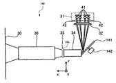
図2は、第1実施形態に係るパターン照射装置20の構成を示す図である。パターン照射装置20は、投影面30に、三次元測定装置21による距離の測定精度を向上させるような画像パターンの光を照射する。投影面30は、ハンドリングシステム10における対象物11が積載されるトレイ12に対応する。   FIG. 2 is a diagram illustrating a configuration of the pattern irradiation apparatus 20 according to the first embodiment. The pattern irradiation device 20 irradiates the projection surface 30 with light of an image pattern that improves the accuracy of distance measurement by the three-dimensional measurement device 21. The projection surface 30 corresponds to the tray 12 on which the object 11 is loaded in the handling system 10.

パターン照射装置20は、発光部31と、集光部32と、透過拡散板33a、33bと、ライトトンネル34と、画像形成部35と、照射光学系36とを備える。
また、ここで2つの透過拡散板33a、33bのうち、ライトトンネル34の光軸x方向上流側すなわち入射側に配置された方を透過拡散板33a、ライトトンネル34のx方向下流側すなわち出射側に配置された方を透過拡散板33bとする。
すなわち、透過拡散板33aは入射側拡散板たる第1拡散部、透過拡散板33bは出射側拡散板たる第2拡散部である。なお、以降の実施形態では第2拡散部が何れも透過拡散板である場合について説明するが、第1拡散部と同様に反射拡散板であっても良い。
The pattern irradiation apparatus 20 includes a light emitting unit 31, a light collecting unit 32, transmission diffusion plates 33 a and 33 b, a light tunnel 34, an image forming unit 35, and an irradiation optical system 36.
Here, of the two transmission diffusion plates 33a and 33b, the one arranged on the upstream side of the light tunnel 34 in the optical axis x direction, that is, the incident side is the transmission diffusion plate 33a and the downstream side of the light tunnel 34 in the x direction, that is, the emission side. The one arranged at is referred to as a transmission diffusion plate 33b.
That is, the transmission diffusion plate 33a is a first diffusion portion that is an incident side diffusion plate, and the transmission diffusion plate 33b is a second diffusion portion that is an output side diffusion plate. In the following embodiments, the case where each of the second diffusing parts is a transmission diffusing plate will be described. However, a reflection diffusing plate may be used as in the case of the first diffusing part.

なお、図中において、x、y、zは、互いに直交する方向を示す。x方向は、ライトトンネル34の光軸に平行な方向を表す。y方向は、x方向に直交する方向を表す。z方向は、x方向およびy方向に直交する方向を表す。   In the figure, x, y, and z indicate directions orthogonal to each other. The x direction represents a direction parallel to the optical axis of the light tunnel 34. The y direction represents a direction orthogonal to the x direction. The z direction represents a direction orthogonal to the x direction and the y direction.

発光部31は、光を出射する。本実施形態において、発光部31は、複数本の平行光束のレーザ光を同一方向に出射する。   The light emitting unit 31 emits light. In the present embodiment, the light emitting unit 31 emits a plurality of parallel light beams in the same direction.

発光部31は、光源である複数のレーザダイオード41と、複数のコリメータレンズ42とを有する。複数のレーザダイオード41は、互いに同一方向に、コヒーレント光であるレーザ光を出射する。本実施形態において、それぞれのレーザダイオード41は、例えば440nm以上500nm以下の波長の青色のレーザ光を発光する青色レーザダイオードである。なお、それぞれのレーザダイオード41は、青色に限らず、他の色であってもよい。また、三次元測定装置21が照射した光を検出できれば、レーザダイオード41は、可視光以外のレーザ光を出射してもよい。   The light emitting unit 31 includes a plurality of laser diodes 41 that are light sources and a plurality of collimator lenses 42. The plurality of laser diodes 41 emit laser light that is coherent light in the same direction. In the present embodiment, each laser diode 41 is a blue laser diode that emits blue laser light having a wavelength of 440 nm to 500 nm, for example. Each laser diode 41 is not limited to blue, but may be other colors. Further, the laser diode 41 may emit laser light other than visible light as long as the light irradiated by the three-dimensional measuring device 21 can be detected.

複数のコリメータレンズ42は、複数のレーザダイオード41のそれぞれに一対一に対応して設けられる。それぞれのコリメータレンズ42は、対応するレーザダイオード41から出射されたレーザ光を入射して、平行光束として出射する。これにより、発光部31は、同一方向に複数本の平行光束のレーザ光を出射することができる。   The plurality of collimator lenses 42 are provided in a one-to-one correspondence with each of the plurality of laser diodes 41. Each collimator lens 42 receives the laser beam emitted from the corresponding laser diode 41 and emits it as a parallel light beam. Thereby, the light emission part 31 can radiate | emit the laser beam of the several parallel light beam in the same direction.

集光部32は、発光部31から出射された光を透過拡散板33a上に集光する。本実施形態においては、集光部32は、レンズであり、複数本のレーザ光を透過拡散板33a上の略一点に集光する。   The condensing part 32 condenses the light radiate | emitted from the light emission part 31 on the permeation | transmission diffusion plate 33a. In this embodiment, the condensing part 32 is a lens, and condenses a plurality of laser beams at approximately one point on the transmission diffusion plate 33a.

透過拡散板33a、33bは、何れも透過した光を拡散させる透過型の拡散部である。透過拡散板33a、33bは、全体が平板状であって、少なくとも一方の平面に微細でランダムな凹凸等が形成されて、一例として、半値全幅の5°以上10°以下の拡散角で光を拡散させる。
透過拡散板33aは、集光部32により集光された複数本のレーザ光を入射し、入射した光を透過して拡散させながらライトトンネル34へと出射する。
透過拡散板33bは、ライトトンネル34を通過した光を透過して拡散させながら画像形成部35へと出射する。
Each of the transmission diffusion plates 33a and 33b is a transmission type diffusion unit that diffuses the transmitted light. The transmissive diffusion plates 33a and 33b are flat as a whole, and fine and random irregularities are formed on at least one plane. For example, the transmission diffusion plates 33a and 33b emit light at a diffusion angle of 5 ° to 10 ° of the full width at half maximum. Spread.
The transmissive diffusion plate 33a receives a plurality of laser beams condensed by the condensing unit 32, and emits the incident light to the light tunnel 34 while diffusing the incident light.
The transmissive diffusion plate 33b emits the light that has passed through the light tunnel 34 to the image forming unit 35 while diffusing the light.

ライトトンネル34は、通過する光の光軸方向(x方向)に垂直な面(y方向およびz方向)の照度分布を均一化する均一化光学系である。ライトトンネル34は、透過拡散板33により拡散された光を入射し、入射した光を通過させて、照度分布を均一化して出射する。ライトトンネル34から出射した光は、透過拡散板33bにより再度拡散される。   The light tunnel 34 is a uniformizing optical system that uniformizes the illuminance distribution on a plane (y direction and z direction) perpendicular to the optical axis direction (x direction) of light passing therethrough. The light tunnel 34 receives the light diffused by the transmissive diffusion plate 33, passes the incident light, and emits the light with a uniform illuminance distribution. The light emitted from the light tunnel 34 is diffused again by the transmission diffusion plate 33b.

画像形成部35は、ライトトンネル34から出射された光を所定の画像パターンに応じて透過および遮断(または反射)して、光軸に垂直な面に所定の画像パターンの像を形成する。画像形成部35を透過した光は、照射光学系36へと入射される。所定の画像パターンは、対象物11に照射した場合に距離測定の精度を向上させる2次元の模様である。   The image forming unit 35 transmits and blocks (or reflects) the light emitted from the light tunnel 34 according to a predetermined image pattern, and forms an image of the predetermined image pattern on a surface perpendicular to the optical axis. The light transmitted through the image forming unit 35 is incident on the irradiation optical system 36. The predetermined image pattern is a two-dimensional pattern that improves the accuracy of distance measurement when the object 11 is irradiated.

画像形成部35は、一例として、ガラス等の透明な板に所定の画像パターンが描かれた長方形の板状のフォトマスクである。また、画像形成部35は、電気信号により透過する画像パターンを形成することができる板状の透過型液晶素子であってもよい。この場合、画像形成部35は、外部の情報処理装置から取り込んだ画像データに応じて画像パターンを形成することができる。   The image forming unit 35 is, for example, a rectangular plate-shaped photomask in which a predetermined image pattern is drawn on a transparent plate such as glass. Further, the image forming unit 35 may be a plate-like transmissive liquid crystal element capable of forming an image pattern that is transmitted by an electric signal. In this case, the image forming unit 35 can form an image pattern according to image data captured from an external information processing apparatus.

照射光学系36は、画像形成部35を透過した光を、指定された倍率に拡大して投影面30に照射する。   The irradiation optical system 36 irradiates the projection surface 30 with the light transmitted through the image forming unit 35 enlarged to a specified magnification.

図3は、ライトトンネル34での光路の一例を示す図である。ライトトンネル34は、図3(a)に示されるように、筒状であって、筒の内部には内側へと光を反射する反射側面43が形成されている。そして、ライトトンネル34は、筒の内部が、光を通過させる光路44として機能する。光路44は、光を通過させることができれば、中空であってもよいし、ガラス等の透明な部材で充填されていてもよい。   FIG. 3 is a diagram illustrating an example of an optical path in the light tunnel 34. As shown in FIG. 3A, the light tunnel 34 has a cylindrical shape, and a reflection side surface 43 that reflects light inward is formed inside the cylinder. The light tunnel 34 functions as an optical path 44 through which light passes. The optical path 44 may be hollow or may be filled with a transparent member such as glass as long as light can pass therethrough.

透過拡散板33aにより拡散された光は、入力口45から光路44内に入射される。入射された光は、反射側面43を反射しながら光路44を通過する。そして、光路44を通過した光は、出力口46から外部へと出射される。このように、ライトトンネル34は、入射された光が反射側面43を反射しながら光路44の内部を通過するので、出射する光の照度分布を均一化することができる。   The light diffused by the transmissive diffusion plate 33 a enters the optical path 44 from the input port 45. The incident light passes through the optical path 44 while being reflected by the reflecting side surface 43. And the light which passed the optical path 44 is radiate | emitted from the output port 46 outside. In this way, the light tunnel 34 passes through the optical path 44 while reflecting the incident side surface 43, so that the illuminance distribution of the emitted light can be made uniform.

また、ライトトンネル34の反射側面43は、光軸に対して平行に設けられている。このため、ライトトンネル34に入射される光の角度θaと、ライトトンネル34から出射される光の角度θbとは同一となる。従って、ライトトンネル34は、出力口46において透過拡散板33aと同一の拡散角の光を出射することができる。
一方、かかる透過拡散板33aが無い場合を考えると、図3(b)に示すように、透過拡散板33aを配置する場合よりもライトトンネル34の入力口45における光の広がり角が小さくなる。
すなわちライトトンネル34の入力口45よりも入射側に透過拡散板33aを配置することで、図3(c)に示すように、ライトトンネル34の出力口46における拡散角が広がる。このように、ライトトンネル34の入力口45における拡散角が大きくなることで、後述するようにライトトンネル34の照度分布の均一化という効果がより向上される。
The reflection side surface 43 of the light tunnel 34 is provided in parallel to the optical axis. For this reason, the angle θa of the light incident on the light tunnel 34 and the angle θb of the light emitted from the light tunnel 34 are the same. Therefore, the light tunnel 34 can emit light having the same diffusion angle as that of the transmission diffusion plate 33a at the output port 46.
On the other hand, when the case where there is no such transmissive diffusion plate 33a, as shown in FIG. 3B, the light spread angle at the input port 45 of the light tunnel 34 becomes smaller than when the transmissive diffusion plate 33a is arranged.
That is, by disposing the transmission diffusion plate 33a on the incident side of the input port 45 of the light tunnel 34, the diffusion angle at the output port 46 of the light tunnel 34 is widened as shown in FIG. As described above, since the diffusion angle at the input port 45 of the light tunnel 34 is increased, the effect of uniforming the illuminance distribution of the light tunnel 34 is further improved as will be described later.

また、本実施形態においては、ライトトンネル34の光軸方向(x方向)に垂直な面の形状は、長方形である。ライトトンネル34の光軸に垂直な面の形状は、画像形成部35と略同一のアスペクト比であることが好ましい。   In the present embodiment, the shape of the surface perpendicular to the optical axis direction (x direction) of the light tunnel 34 is a rectangle. The shape of the surface perpendicular to the optical axis of the light tunnel 34 preferably has substantially the same aspect ratio as that of the image forming unit 35.

また、ライトトンネル34の出力口46は、少なくとも後段の画像形成部35の全面に光が照射できる大きさであればよい。もっとも、出力口46は、後段の画像形成部35よりも大きい場合には、出射された光が画像形成部35の外部に漏れて無駄になるので、組み付け精度等を考慮して画像形成部35と略同一程度にするのが好ましい。   Further, the output port 46 of the light tunnel 34 may be of a size that can irradiate light on at least the entire surface of the image forming unit 35 in the subsequent stage. Of course, if the output port 46 is larger than the image forming unit 35 at the subsequent stage, the emitted light leaks outside the image forming unit 35 and is wasted. Therefore, the image forming unit 35 is considered in consideration of assembly accuracy and the like. It is preferable to make it substantially the same.

また、ライトトンネル34は、光軸方向の長さが長いほど、光路44内での光の反射回数が増えて照度分布をより均一化することができるが、損失も大きくなる。従って、ライトトンネル34の光軸方向の長さは、目的の均一化度が得られる最小の長さであることが好ましい。   Further, the longer the length of the light tunnel 34 in the optical axis direction, the more the number of times the light is reflected in the optical path 44 and the more uniform the illuminance distribution, but the loss also increases. Therefore, it is preferable that the length of the light tunnel 34 in the optical axis direction is a minimum length that can achieve a desired degree of uniformity.

なお、ライトトンネル34は、ホモジナイザまたはライトパイプと呼ばれる場合もある。また、パターン照射装置20は、均一化光学系であれば、ライトトンネル34に代えて他の部材を備えてもよい。例えば、パターン照射装置20は、ライトトンネル34に代えてフライアイを備えてもよい。
ライトトンネル34の照度分布を均一化する効果と、透過拡散板32bの効果とについてさらに詳しく説明する。
ライトトンネル34に入射する光の角度θaに広がりを持つ光は、角度θa毎にライトトンネル34内部での反射回数が異なり、結果としてライトトンネル34の出力口46で図3(c)に示すようにyz平面での位置が光線入射角ごとに異なる。言い換えると、出力口46におけるそれぞれの光線の位置は、ライトトンネル34に入射した光の広がり角に対応することを意味する。したがって、ライトトンネル34に入射する光の広がり角が大きいほど、出力口46におけるyz平面上の出射位置が異なって照度分布が均一化されやすい。
また、既に図3(a)に示したように、単一の光線について入射される光の角度θaと、出射される光の角度θbとは同一となる。したがってかりに入力口45における光線が点で入射されるときには、出力口46においてそれぞれの位置から出射される光は広がり角が小さい。
逆に言うと、ライトトンネル34から出射される光のyz平面の各像高における光線の広がり角は、入射スポットの面積が大きく様々な角度成分を持つ光が入射するほど大きくなる。本実施形態においては入射光はレーザ光であり、入力口45における光線のライトトンネル34への入射スポットが入力口45に対して比較的小さい。このような場合には、ライトトンネル34から出射される光のyz平面の各像高における光線の広がり角は小さくなる。
従って、ライトトンネル34の出射側である+x方向側に画像形成部35を置いた場合、画像形成部35における各像高での入射角度範囲はそれぞれライトトンネル34の入射光角度範囲以下となる。結果として、照射光学系36での各像高の光の広がり角もライトトンネル34に入射した光の広がり角に対応するため、広がり角が小さい。そのため、照射光学系36内を進行する各像高の光は密度が高く、各光学部材への照射密度も高くなる。照射光学系36への照射密度が高くなることは、光学部材への負荷の増大を招くおそれがある。
The light tunnel 34 may be called a homogenizer or a light pipe. Further, the pattern irradiation device 20 may include other members instead of the light tunnel 34 as long as it is a homogenizing optical system. For example, the pattern irradiation device 20 may include a fly eye instead of the light tunnel 34.
The effect of making the illuminance distribution of the light tunnel 34 uniform and the effect of the transmission diffusion plate 32b will be described in more detail.
The light having a spread at the angle θa of the light incident on the light tunnel 34 has a different number of reflections inside the light tunnel 34 for each angle θa. As a result, as shown in FIG. 3C at the output port 46 of the light tunnel 34. The position on the yz plane differs for each ray incident angle. In other words, the position of each light beam at the output port 46 corresponds to the spread angle of the light incident on the light tunnel 34. Therefore, as the spread angle of the light incident on the light tunnel 34 is larger, the emission position on the yz plane at the output port 46 is different, and the illuminance distribution is more easily made uniform.
In addition, as already shown in FIG. 3A, the angle θa of the incident light and the angle θb of the emitted light are the same for a single light beam. Therefore, when the light beam at the input port 45 is incident as a point, the light emitted from each position at the output port 46 has a small divergence angle.
In other words, the spread angle of the light beam at each image height on the yz plane of the light emitted from the light tunnel 34 becomes larger as the incident spot has a larger area and incident light having various angle components. In the present embodiment, the incident light is laser light, and the incident spot of the light beam at the input port 45 to the light tunnel 34 is relatively small with respect to the input port 45. In such a case, the spread angle of the light beam at each image height on the yz plane of the light emitted from the light tunnel 34 becomes small.
Accordingly, when the image forming unit 35 is placed on the + x direction side that is the emission side of the light tunnel 34, the incident angle range at each image height in the image forming unit 35 is equal to or smaller than the incident light angle range of the light tunnel 34. As a result, the spread angle of the light at each image height in the irradiation optical system 36 also corresponds to the spread angle of the light incident on the light tunnel 34, so the spread angle is small. Therefore, the light of each image height traveling in the irradiation optical system 36 has a high density, and the irradiation density to each optical member also increases. An increase in the irradiation density to the irradiation optical system 36 may increase the load on the optical member.

そこで、本発明では、図2や図3(c)に示したようにライトトンネル34と画像形成部35との間に透過拡散板33bを配置している。かかる構成により、ライトトンネル34から出射した広がり角の小さな各像高の光が、透過拡散板33bを通ることで広がり角が大きくなる。結果として、照射光学系36内の各レンズへの照射密度も低くなり、光学部品の劣化を防ぐことができる。また、レーザークラスを低減することもできる。
なお、ライトトンネル34の後に拡散板を入れることにより照射光学系36内の各レンズの劣化を防ぐことができる効果は以下の実施例でも同様に得ることが出来る。
以上述べたように、透過拡散板33aと、透過拡散板33bとをライトトンネル34の前後に配置することで、入力口45における光の広がり角を大きくするとともに、入射スポットをも拡げるから、透過拡散板33bの拡散効果がより顕著に生じる。
本実施形態のようにライトトンネル34の入射側と出射側の両面に透過拡散板33a、33bを配置することで、透過拡散板33aで投射面に光が均一に照射されるとともに、透過拡散板33bで照射光学系36への照射密度が低減される。
また、透過拡散板33aと透過拡散板33bとの拡散角は、照射光学系36への入射光の広がり角が、照射光学系36の画像形成部35側の開口数(NA)から導出される角度以下に抑えられるように選択されることが望ましい。このように照射光学系36の開口数を用いて透過拡散板33aと透過拡散板33bとの拡散角が設定されることで、画像形成部35から照射光学系36への入射光が効率よく投影面30へと導かれるから、高出力で均一な光が投射される。
Therefore, in the present invention, the transmission diffusion plate 33b is disposed between the light tunnel 34 and the image forming unit 35 as shown in FIG. 2 and FIG. With such a configuration, the light having a small spread angle emitted from the light tunnel 34 passes through the transmission diffusion plate 33b, so that the spread angle becomes large. As a result, the irradiation density to each lens in the irradiation optical system 36 is also reduced, and deterioration of the optical components can be prevented. In addition, the laser class can be reduced.
The effect of preventing deterioration of each lens in the irradiation optical system 36 by inserting a diffusion plate after the light tunnel 34 can also be obtained in the following embodiments.
As described above, the transmission diffusion plate 33a and the transmission diffusion plate 33b are arranged before and after the light tunnel 34, so that the light spreading angle at the input port 45 is increased and the incident spot is also expanded. The diffusion effect of the diffusion plate 33b is more noticeable.
By arranging the transmission diffusion plates 33a and 33b on both the incident side and the emission side of the light tunnel 34 as in the present embodiment, the transmission surface is uniformly irradiated with light by the transmission diffusion plate 33a, and the transmission diffusion plate. In 33b, the irradiation density to the irradiation optical system 36 is reduced.
The diffusion angle between the transmission diffusion plate 33a and the transmission diffusion plate 33b is derived from the numerical aperture (NA) of the irradiation optical system 36 on the image forming unit 35 side as the spread angle of the incident light to the irradiation optical system 36. It is desirable to select such that the angle is suppressed to an angle or less. Thus, by setting the diffusion angle between the transmission diffusion plate 33a and the transmission diffusion plate 33b using the numerical aperture of the irradiation optical system 36, the incident light from the image forming unit 35 to the irradiation optical system 36 is efficiently projected. Since the light is guided to the surface 30, high power and uniform light is projected.

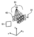
図4は、第1実施形態に係るパターン照射装置20の一部分の斜視図である。発光部31は、一例として、2×4のマトリクス状に配列された8個のレーザダイオード41を有する。さらに、発光部31は、それぞれのレーザダイオード41に対応して設けられた8個のコリメータレンズ42を有する。このような発光部31は、同一方向に8本の平行光束を出射することができる。   FIG. 4 is a perspective view of a part of the pattern irradiation apparatus 20 according to the first embodiment. As an example, the light emitting unit 31 includes eight laser diodes 41 arranged in a 2 × 4 matrix. Further, the light emitting unit 31 includes eight collimator lenses 42 provided corresponding to the respective laser diodes 41. Such a light emitting unit 31 can emit eight parallel light beams in the same direction.

このように、発光部31は、複数個のレーザダイオード41を有するので、出力する光のエネルギーを大きくすることができる。なお、発光部31が有するレーザダイオード41の個数および配置は、同一方向にレーザ光を出射できれば、どのような個数および配置であってもよい。   Thus, since the light emission part 31 has the several laser diode 41, the energy of the light to output can be enlarged. Note that the number and arrangement of the laser diodes 41 included in the light emitting unit 31 may be any number and arrangement as long as laser light can be emitted in the same direction.

また、透過拡散板33aは、リレー光学系等を介さずに、ライトトンネル34の直前に配置されている。これにより、パターン照射装置20は、透過拡散板33とライトトンネル34の間の光学的な距離を短くして、拡散した光がライトトンネル34の外部へと漏れてしまうことを防止することができる。従って、パターン照射装置20は、光の伝達の効率を高め、出力するエネルギーを大きくすることができる。   Further, the transmission diffusion plate 33a is disposed immediately before the light tunnel 34 without using a relay optical system or the like. Thereby, the pattern irradiation apparatus 20 can shorten the optical distance between the transmission diffusion plate 33 and the light tunnel 34 and prevent the diffused light from leaking outside the light tunnel 34. . Therefore, the pattern irradiation device 20 can increase the efficiency of light transmission and increase the output energy.

また、集光部32は、発光部31から出射された複数本のレーザ光を透過拡散板33上に集光する。従って、発光部31が有するレーザダイオード41の個数を増加させても、レーザダイオード41から出射された光をライトトンネル34内に漏れなく入射させることができる。従って、パターン照射装置20は、出力するエネルギーを容易に大きくすることができる。   The condensing unit 32 condenses a plurality of laser beams emitted from the light emitting unit 31 on the transmission diffusion plate 33. Therefore, even if the number of laser diodes 41 included in the light emitting unit 31 is increased, the light emitted from the laser diode 41 can be incident on the light tunnel 34 without leakage. Therefore, the pattern irradiation apparatus 20 can easily increase the energy to be output.

また、レーザ光は直進性が高い。従って、もし、コリメータレンズ42から出射されたレーザ光を直接入射した場合、ライトトンネル34は、照度分布を効率良く均一化させることは困難である。しかし、本実施形態において、ライトトンネル34は、透過拡散板33aにより拡散されたレーザ光を入射するので、照度分布を効率良く均一化することができる。従って、パターン照射装置20は、ライトトンネル34の光軸方向の長さを短くして装置の小型化を図ることができる。   Further, the laser beam has high straightness. Therefore, if the laser light emitted from the collimator lens 42 is directly incident, it is difficult for the light tunnel 34 to efficiently uniformize the illuminance distribution. However, in the present embodiment, the light tunnel 34 receives the laser light diffused by the transmission diffusion plate 33a, so that the illuminance distribution can be made uniform efficiently. Therefore, the pattern irradiation apparatus 20 can reduce the length of the light tunnel 34 in the optical axis direction and reduce the size of the apparatus.

またさらに、ライトトンネル34と、透過拡散板33bと、画像形成部35との間の光学的な距離は短いことが好ましい。かかる構成により、パターン照射装置20は、ライトトンネル34から出射され拡散された光が光路外に漏れてしまうことを防止して、照度分布が均一化された光が高効率に照射光学系36に導かれる。
また、画像形成部35は、リレー光学系等を介さずに、ライトトンネル34の直後に配置されている。これにより、パターン照射装置20は、ライトトンネル34と画像形成部35との光学的な距離を短くして、ライトトンネル34から出射された拡散された光が外部へと漏れてしまうことを防止することができる。従って、パターン照射装置20は、光の伝達の効率を高め、出力するエネルギーを大きくすることができる。
Furthermore, it is preferable that the optical distance between the light tunnel 34, the transmissive diffusion plate 33b, and the image forming unit 35 is short. With this configuration, the pattern irradiation device 20 prevents the light emitted from the light tunnel 34 and diffused from leaking out of the optical path, and the light with a uniform illuminance distribution is efficiently applied to the irradiation optical system 36. Led.
Further, the image forming unit 35 is disposed immediately after the light tunnel 34 without using a relay optical system or the like. As a result, the pattern irradiation device 20 shortens the optical distance between the light tunnel 34 and the image forming unit 35 and prevents the diffused light emitted from the light tunnel 34 from leaking to the outside. be able to. Therefore, the pattern irradiation device 20 can increase the efficiency of light transmission and increase the output energy.

また、本実施形態においては、レーザダイオード41は、青色のレーザ光を発光する。これにより、パターン照射装置20は、より精度良く距離測定をさせることができるとともに、作業者に良好な作業環境を提供することができる。この理由は、以下の通りである。   In the present embodiment, the laser diode 41 emits blue laser light. Thereby, the pattern irradiation apparatus 20 can measure the distance with higher accuracy and can provide a good working environment to the worker. The reason for this is as follows.

例えば、オスラム株式会社のプロジェクタ用の光源P1Wが知られている(http://www.osram.jp/osram_jp/press/press-releases/_trade_press/2013/osram-led-power-packs-for-projectors/)。この光源P1Wは、青色が500lm、赤色が1250lm、緑色が4150lmの明るさで発光する。lmは、光束の単位であり、視感度を考慮した明るさである。視感度を考慮しない光の放射束(単位W)は、光束(lm)=683×放射束(W)×Y刺激値により算出される。各色の代表的なスペクトルから換算係数lm/Wを算出した場合、青色が40lm/W、赤色が200lm/W、緑色が480lm/Wとなる。よって、放射束は、光束と換算係数より、青色が12.5W、赤色が6.3W、緑色が8.6Wとなる。つまり、放射束は、青色が最も高い。   For example, the light source P1W for projectors of OSRAM is known (http://www.osram.jp/osram_jp/press/press-releases/_trade_press/2013/osram-led-power-packs-for-projectors /). The light source P1W emits light with brightness of 500 lm for blue, 1250 lm for red, and 4150 lm for green. lm is a unit of luminous flux and is brightness in consideration of visibility. The radiant flux (unit W) of light that does not consider the visibility is calculated by the luminous flux (lm) = 683 × radiant flux (W) × Y stimulus value. When the conversion factor lm / W is calculated from the representative spectrum of each color, blue is 40 lm / W, red is 200 lm / W, and green is 480 lm / W. Therefore, the radiant flux is 12.5 W for blue, 6.3 W for red, and 8.6 W for green based on the luminous flux and the conversion factor. That is, the radiant flux is the highest in blue.

距離測定のための画像パターンを照射するパターン照射装置20では、人の目の感度、つまり視感度の考慮された光束量ではなく、純粋な光の出力である放射束が高い光源を備えることが好ましい。青色レーザダイオードは、上述のように販売されている光源のうち、高い放射束が得られる。従って、レーザダイオード41が青色のレーザ光を出射するので、パターン照射装置20は、対象物11を高いエネルギーで照明でき、対象物11が黒色等であっても精度良く距離測定をさせることができる。   The pattern irradiation apparatus 20 that irradiates an image pattern for distance measurement includes a light source that has a high radiant flux, which is a pure light output, rather than a luminous flux considering human eye sensitivity, that is, visibility. preferable. The blue laser diode can obtain a high radiant flux among the light sources sold as described above. Therefore, since the laser diode 41 emits blue laser light, the pattern irradiation apparatus 20 can illuminate the object 11 with high energy, and can accurately measure the distance even if the object 11 is black or the like. .

一方、青色は、光束が低く、人の目には眩しくない。従って、レーザダイオード41が青色のレーザ光を出射するので、パターン照射装置20は、作業者が対象物11を目視しやすく、良好な作業環境を提供することができる。また、青色は、可視光である。従って、レーザダイオード41が青色のレーザ光を出射するので、パターン照射装置20は、作業者に照明エリアを目視させることができ、作業者が照明エリアを調整しやすい環境を提供することができる。   On the other hand, blue light has a low luminous flux and is not dazzling to human eyes. Therefore, since the laser diode 41 emits blue laser light, the pattern irradiation device 20 can provide a good working environment because the operator can easily see the object 11. Blue is visible light. Therefore, since the laser diode 41 emits blue laser light, the pattern irradiating device 20 can allow the operator to visually observe the illumination area, and can provide an environment in which the operator can easily adjust the illumination area.

以上のように、本実施形態に係るパターン照射装置20によれば、高い光出力を得られるとともに、サイズおよびコストを小さくすることができる。さらに、パターン照射装置20は、作業者に良好な作業環境を提供することができる。   As described above, according to the pattern irradiation apparatus 20 according to the present embodiment, high light output can be obtained, and the size and cost can be reduced. Furthermore, the pattern irradiation apparatus 20 can provide a favorable working environment for the worker.

(第2実施形態)
つぎに、第2実施形態に係るパターン照射装置50について説明する。第2実施形態に係るパターン照射装置50は、第1実施形態に係るパターン照射装置20に代えて、ハンドリングシステム10に適用される。なお、第3実施形態以降も同様である。
(Second Embodiment)
Next, a pattern irradiation apparatus 50 according to the second embodiment will be described. The pattern irradiation apparatus 50 according to the second embodiment is applied to the handling system 10 instead of the pattern irradiation apparatus 20 according to the first embodiment. The same applies to the third and subsequent embodiments.

また、第2実施形態に係るパターン照射装置50は、第1実施形態に係るパターン照射装置20と略同一の機能および構成を有する。略同一の機能および構成を有する部材については、同一の符号を付けて、相違点を除き詳細な説明を省略する。   Further, the pattern irradiation apparatus 50 according to the second embodiment has substantially the same function and configuration as the pattern irradiation apparatus 20 according to the first embodiment. Members having substantially the same function and configuration are denoted by the same reference numerals, and detailed description thereof is omitted except for differences.

図5は、第2実施形態に係るパターン照射装置50の構成を示す図である。パターン照射装置50は、発光部31と、集光部32と、反射拡散板51と、ライトトンネル34と、画像形成部35と、照射光学系36とを備える。パターン照射装置50は、第1拡散部として、透過拡散板33aに代えて反射拡散板51を備える点で、第1実施形態と異なる。   FIG. 5 is a diagram illustrating a configuration of a pattern irradiation apparatus 50 according to the second embodiment. The pattern irradiation device 50 includes a light emitting unit 31, a light collecting unit 32, a reflective diffusion plate 51, a light tunnel 34, an image forming unit 35, and an irradiation optical system 36. The pattern irradiation device 50 is different from the first embodiment in that a reflection diffusion plate 51 is provided instead of the transmission diffusion plate 33a as the first diffusion unit.

集光部32は、発光部31から出射された光を反射拡散板51上に集光する。本実施形態においては、集光部32は、複数本のレーザ光を反射拡散板51上の略一点に集光する。   The condensing unit 32 condenses the light emitted from the light emitting unit 31 on the reflection diffusion plate 51. In the present embodiment, the condensing unit 32 condenses a plurality of laser beams at approximately one point on the reflection diffusion plate 51.

反射拡散板51は、入射した光を拡散させる第1拡散部である。反射拡散板51は、集光部32により集光された複数本のレーザ光を入射して、入射した光を反射して拡散させながらライトトンネル34へと出射する。反射拡散板51は、光を反射して拡散させる点において、透過拡散板33aと異なるが、他の機能および効果について透過拡散板33と同一である。   The reflection diffusion plate 51 is a first diffusion unit that diffuses incident light. The reflection diffusing plate 51 receives a plurality of laser beams condensed by the condensing unit 32 and emits the incident light to the light tunnel 34 while reflecting and diffusing the incident light. The reflection diffusion plate 51 is different from the transmission diffusion plate 33a in that light is reflected and diffused, but is the same as the transmission diffusion plate 33 in other functions and effects.

ライトトンネル34は、反射拡散板51により拡散された光を入射し、照度分布を均一化して出射する。   The light tunnel 34 receives the light diffused by the reflection diffusing plate 51, and emits the light with a uniform illuminance distribution.

図6は、反射拡散板51での光路の一例を示す図である。反射拡散板51は、全体が略平板状であって、集光部32側に形成された透過拡散面52と、集光部32とは反対側に形成された反射面53とを含む。   FIG. 6 is a diagram illustrating an example of an optical path in the reflection diffusing plate 51. The reflection diffusion plate 51 is substantially flat as a whole, and includes a transmission diffusion surface 52 formed on the light collecting unit 32 side and a reflection surface 53 formed on the opposite side of the light collection unit 32.

透過拡散面52は、微細でランダムな凹凸が形成されている。透過拡散面52は、光を透過させるとともに、透過する光を拡散させる。透過拡散面52の表面には、反射防止膜が形成されていてもよい。これにより、透過拡散面52は、透過率を高くすることができる。   The transmission diffusion surface 52 is formed with fine and random irregularities. The transmission diffusion surface 52 transmits light and diffuses the transmitted light. An antireflection film may be formed on the surface of the transmission diffusion surface 52. Thereby, the transmission diffusion surface 52 can increase the transmittance.

反射面53は、集光部32から入射して透過拡散面52を透過した光を反射する。反射面53は、一例として、平面であり、光を拡散させない。反射面53は、誘電体多層膜または金属膜等の反射コーティング膜が表面に形成されていてもよい。これにより、反射面53は、反射率を高くすることができる。反射面53を反射した光は、再度、透過拡散面52を透過して、ライトトンネル34へと入射される。   The reflecting surface 53 reflects the light that has entered the condensing unit 32 and has passed through the transmissive diffusing surface 52. As an example, the reflecting surface 53 is a flat surface and does not diffuse light. The reflective surface 53 may have a reflective coating film such as a dielectric multilayer film or a metal film formed on the surface thereof. Thereby, the reflective surface 53 can make a reflectance high. The light reflected from the reflection surface 53 is transmitted through the transmission diffusion surface 52 again and is incident on the light tunnel 34.

このような反射拡散板51に対して、図6に示されるように、集光部32から光束aが入射されたとする。この場合、光束aは、透過拡散面52の表面側から入射する。そして、光束aは、透過拡散面52において透過および拡散して、拡散光束a1、a2となる。ここでは、拡散光束a1、a2のみを示しているが、光束aの拡散光束は多数存在する。   As shown in FIG. 6, it is assumed that a light beam a is incident on the reflection diffusing plate 51 from the light collector 32. In this case, the light beam a enters from the surface side of the transmission diffusion surface 52. Then, the light beam a is transmitted and diffused on the transmission diffusion surface 52 to become diffused light beams a1 and a2. Here, only the diffused light beams a1 and a2 are shown, but there are many diffused light beams of the light beam a.

続いて、拡散光束a1、a2は、反射面53において反射され、再度、透過拡散面52に裏面側から入射する。そして、拡散光束a1、a2は、透過拡散面52においてそれぞれ透過および拡散して、拡散光束a11、a12、a21、a22となる。ここでは、拡散光束a11、a12、a21、a22のみを示しているが、光束a1、a2の拡散光束は多数存在する。   Subsequently, the diffused light beams a <b> 1 and a <b> 2 are reflected by the reflection surface 53 and enter the transmission diffusion surface 52 again from the back surface side. Then, the diffused light beams a1 and a2 are transmitted and diffused on the transmission diffusion surface 52, respectively, to become diffused light beams a11, a12, a21, and a22. Here, only diffused light beams a11, a12, a21, and a22 are shown, but there are many diffused light beams of light beams a1 and a2.

このように、このような構成の反射拡散板51は、光を透過拡散面52で2回拡散させることができる。これにより、反射拡散板51は、拡散効果を高めて、より照度分布が均一な光を出射させることができる。従って、本実施形態に係るパターン照射装置50によれば、より照度分布が均一な画像パターンを対象物11に照射することができる。   Thus, the reflection diffusing plate 51 having such a configuration can diffuse light twice on the transmission diffusing surface 52. Thereby, the reflective diffusion plate 51 can enhance the diffusion effect and emit light with a more uniform illuminance distribution. Therefore, according to the pattern irradiation apparatus 50 according to the present embodiment, the object 11 can be irradiated with an image pattern with a more uniform illuminance distribution.

なお、本実施形態においては、反射拡散板51の集光部32側の面を透過拡散面52としているが、これに代えて、反射拡散板51の集光部32側の面を拡散および反射をする反射拡散面としてもよい。   In this embodiment, the surface on the light condensing part 32 side of the reflection diffusion plate 51 is used as the transmission diffusion surface 52. Instead, the surface on the light condensing part 32 side of the reflection diffusion plate 51 is diffused and reflected. It is good also as a reflective diffusion surface which carries out.

以上のように、本実施形態に係るパターン照射装置50によれば、反射拡散板51を備えるので、より均一化した光を出力することができる。   As described above, according to the pattern irradiation apparatus 50 according to the present embodiment, since the reflection diffusing plate 51 is provided, more uniform light can be output.

図7は、反射拡散板51が脱落した場合の光路の一例を示す図である。本実施形態に係るパターン照射装置50において、故障等により反射拡散板51が脱落または破損等をして、レーザ光が反射拡散板51で反射されなかったとする。この場合、図7に示されるように、発光部31から出射されたレーザ光は、ライトトンネル34に入射されない。従って、この場合、パターン照射装置50は、投影面30に何ら光を照射しない。   FIG. 7 is a diagram illustrating an example of an optical path when the reflective diffusion plate 51 is dropped. In the pattern irradiation apparatus 50 according to the present embodiment, it is assumed that the reflection diffusion plate 51 is dropped or damaged due to a failure or the like, and the laser light is not reflected by the reflection diffusion plate 51. In this case, as shown in FIG. 7, the laser light emitted from the light emitting unit 31 is not incident on the light tunnel 34. Therefore, in this case, the pattern irradiation device 50 does not irradiate the projection surface 30 with any light.

このため、パターン照射装置50は、反射拡散板51が脱落または破損等をした場合において、レーザ光が拡散されずに直接外部へと出射されない。これにより、パターン照射装置50は、拡散部が脱落または破損したときのレーザ光の出射防止機構を簡単な構成で実現することができる。   For this reason, in the pattern irradiation apparatus 50, when the reflection diffusion plate 51 is dropped or damaged, the laser beam is not directly emitted to the outside without being diffused. Thereby, the pattern irradiation apparatus 50 can implement | achieve the radiation | emission prevention mechanism of a laser beam when a spreading | diffusion part falls or is damaged with a simple structure.

(第3実施形態)
つぎに、第3実施形態に係るパターン照射装置60について説明する。第3実施形態に係るパターン照射装置60は、第2実施形態に係るパターン照射装置50と略同一の機能および構成を有する。略同一の機能および構成を有する部材については、同一の符号を付けて、相違点を除き詳細な説明を省略する。
(Third embodiment)
Next, a pattern irradiation apparatus 60 according to the third embodiment will be described. The pattern irradiation apparatus 60 according to the third embodiment has substantially the same function and configuration as the pattern irradiation apparatus 50 according to the second embodiment. Members having substantially the same function and configuration are denoted by the same reference numerals, and detailed description thereof is omitted except for differences.

図8は、第3実施形態に係るパターン照射装置60の構成を示す図である。パターン照射装置60は、発光部31と、集光部32と、反射拡散板51と、テーパライトトンネル61と、画像形成部35と、照射光学系36とを備える。パターン照射装置60は、均一化光学系として、ライトトンネル34に代えてテーパライトトンネル61を備える点で、第2実施形態と異なる。   FIG. 8 is a diagram illustrating a configuration of a pattern irradiation apparatus 60 according to the third embodiment. The pattern irradiation device 60 includes a light emitting unit 31, a light collecting unit 32, a reflection diffusing plate 51, a taper light tunnel 61, an image forming unit 35, and an irradiation optical system 36. The pattern irradiation device 60 is different from the second embodiment in that a taper light tunnel 61 is provided instead of the light tunnel 34 as a uniformizing optical system.

テーパライトトンネル61は、反射拡散板51により拡散された光を入射して、照度分布を均一化して出射する。テーパライトトンネル61は、形状は異なるが、ライトトンネル34と略同一の構成および機能を有する。   The taper light tunnel 61 receives the light diffused by the reflective diffusion plate 51 and emits it with a uniform illuminance distribution. The tapered light tunnel 61 has substantially the same configuration and function as the light tunnel 34, although the shape is different.

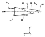
図9は、テーパライトトンネル61での光路の一例を示す図である。テーパライトトンネル61は、図9に示されるように、入力口64より出力口65が大きく、反射側面62が光路63の光軸に対して傾けて形成されている点において、ライトトンネル34と異なる。また、テーパライトトンネル61は、光路63における光軸に垂直方向の面の形状(入力口64および出力口65の形状を含む)は、画像形成部35と略同一のアスペクト比の長方形である。   FIG. 9 is a diagram illustrating an example of an optical path in the tapered light tunnel 61. As shown in FIG. 9, the tapered light tunnel 61 is different from the light tunnel 34 in that the output port 65 is larger than the input port 64 and the reflection side surface 62 is formed to be inclined with respect to the optical axis of the optical path 63. . In addition, the tapered light tunnel 61 has a rectangular shape with an aspect ratio substantially the same as that of the image forming unit 35 in the shape of the surface perpendicular to the optical axis in the optical path 63 (including the shapes of the input port 64 and the output port 65).

このようなテーパライトトンネル61は、ライトトンネル34と同様に、入射された光が反射側面62を反射しながら光路63の内部を通過するので、出射する光の照度分布を均一化することができる。   Such a tapered light tunnel 61, like the light tunnel 34, allows the incident light to pass through the inside of the optical path 63 while reflecting the reflecting side surface 62, so that the illuminance distribution of the emitted light can be made uniform. .

ここで、テーパライトトンネル61におけるz方向に垂直な反射側面62は、光軸に対して角度θtでz方向に傾いている。従って、テーパライトトンネル61は、入射される光の角度θcより、出射される光の角度θdの方を小さくすることができる。テーパライトトンネル61は、後段の画像形成部35への光の角度(拡散角)を小さくすることができる。   Here, the reflective side surface 62 perpendicular to the z direction in the tapered light tunnel 61 is inclined in the z direction at an angle θt with respect to the optical axis. Therefore, the tapered light tunnel 61 can make the angle θd of the emitted light smaller than the angle θc of the incident light. The taper light tunnel 61 can reduce the angle of light (diffusion angle) to the subsequent image forming unit 35.

これにより、パターン照射装置60は、テーパライトトンネル61を備えることで、画像形成部35を通過した後の照射光学系36への光線入射角を小さく、つまり、NAを小さくできる。このため、パターン照射装置60は、照射光学系36への光の取り込み効率を上げて高い光出力を得ることができる。   Thereby, the pattern irradiation apparatus 60 includes the tapered light tunnel 61, so that the light incident angle to the irradiation optical system 36 after passing through the image forming unit 35 can be reduced, that is, the NA can be reduced. For this reason, the pattern irradiation apparatus 60 can increase the efficiency of capturing light into the irradiation optical system 36 and obtain a high light output.

なお、テーパライトトンネル61は、反射側面62の傾きの角度θtを大きくするほど、出射される光の角度θdを小さくすることができる。傾きの角度θtを大きくするには、入力口64を小さくするか、または、出力口65を大きくすればよい。しかしながら、入力口64を小さくすると、反射拡散板51で反射した光を効率良く取り込むことが困難になり、出力口65を大きくすると画像形成部35より外側を照明する光が無駄となる。従って、傾きの角度θt、入力口64のサイズおよび出力口65のサイズは、これらを考慮しながら適切に設定することが好ましい。   The tapered light tunnel 61 can reduce the angle θd of the emitted light as the angle of inclination θt of the reflecting side surface 62 is increased. In order to increase the inclination angle θt, the input port 64 may be reduced or the output port 65 may be increased. However, if the input port 64 is made smaller, it becomes difficult to efficiently capture the light reflected by the reflection diffusion plate 51, and if the output port 65 is made larger, the light that illuminates the outside of the image forming unit 35 is wasted. Accordingly, it is preferable to appropriately set the inclination angle θt, the size of the input port 64, and the size of the output port 65 in consideration of these.

また、テーパライトトンネル61は、入力口64および出力口65のサイズを固定した状態において光軸方向を長くすると、反射回数は増えて照度分布をより均一化することができる。しかし、テーパライトトンネル61は、光軸方向を長くすると、反射回数増加により効率が低下し、さらに、傾きの角度θtが小さくなり照射光学系36での取り込み効率が低下する。従って、テーパライトトンネル61の光軸方向の長さは、これらを考慮しながら適切に設定することが好ましい。   Further, when the optical axis direction is lengthened in the state where the sizes of the input port 64 and the output port 65 are fixed, the taper light tunnel 61 can increase the number of reflections and make the illuminance distribution more uniform. However, when the length of the optical axis of the taper light tunnel 61 is increased, the efficiency is reduced due to an increase in the number of reflections, and the inclination angle θt is reduced, so that the capturing efficiency in the irradiation optical system 36 is reduced. Therefore, it is preferable that the length of the taper light tunnel 61 in the optical axis direction is appropriately set in consideration of these.

以上のように、本実施形態に係るパターン照射装置60によれば、テーパライトトンネル61を備えるので、高出力化を図ることができる。   As described above, according to the pattern irradiation apparatus 60 according to the present embodiment, since the tapered light tunnel 61 is provided, high output can be achieved.

(第4実施形態)
つぎに、第4実施形態に係るパターン照射装置70について説明する。第4実施形態に係るパターン照射装置70は、第3実施形態に係るパターン照射装置60と略同一の機能および構成を有する。略同一の機能および構成を有する部材については、同一の符号を付けて、相違点を除き詳細な説明を省略する。
(Fourth embodiment)
Next, a pattern irradiation apparatus 70 according to the fourth embodiment will be described. The pattern irradiation apparatus 70 according to the fourth embodiment has substantially the same function and configuration as the pattern irradiation apparatus 60 according to the third embodiment. Members having substantially the same function and configuration are denoted by the same reference numerals, and detailed description thereof is omitted except for differences.

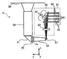
図10は、第4実施形態に係るパターン照射装置70の構成を示す図である。パターン照射装置70は、発光部31と、集光部32と、反射拡散板51と、テーパライトトンネル61、画像形成部35と、プリズム71と、照射光学系36とを備える。集光部32は、第1のミラー群72と、レンズ73とを有する。   FIG. 10 is a diagram illustrating a configuration of a pattern irradiation apparatus 70 according to the fourth embodiment. The pattern irradiation device 70 includes a light emitting unit 31, a light collecting unit 32, a reflection diffusing plate 51, a taper light tunnel 61, an image forming unit 35, a prism 71, and an irradiation optical system 36. The condensing unit 32 includes a first mirror group 72 and a lens 73.

パターン照射装置70は、プリズム71をさらに備える点で、第3実施形態と異なる。また、パターン照射装置70は、集光部32が第1のミラー群72とレンズ73とを有する点で、第3実施形態と異なる。   The pattern irradiation device 70 is different from the third embodiment in that it further includes a prism 71. Further, the pattern irradiation device 70 is different from the third embodiment in that the light collecting unit 32 includes a first mirror group 72 and a lens 73.

第1のミラー群72は、発光部31から同一方向に出射された複数本の平行光束を反射してレンズ73へと導く。第1のミラー群72は、複数のミラー74を有する。それぞれのミラー74は、レーザダイオード41から出射されてコリメータレンズ42により平行光束とされたレーザ光を、レンズ73の方向に反射する。複数のミラー74は、複数本の平行光束を同一方向に、すなわち、複数本の平行光束を平行に反射する。   The first mirror group 72 reflects and guides a plurality of parallel light beams emitted from the light emitting unit 31 in the same direction to the lens 73. The first mirror group 72 has a plurality of mirrors 74. Each mirror 74 reflects the laser light emitted from the laser diode 41 and converted into a parallel light beam by the collimator lens 42 in the direction of the lens 73. The plurality of mirrors 74 reflect a plurality of parallel light beams in the same direction, that is, a plurality of parallel light beams are reflected in parallel.

レンズ73は、平行に入射された複数の平行光束を反射拡散板51上の略一点に集光する。   The lens 73 condenses a plurality of parallel light beams incident in parallel on one point on the reflection diffusion plate 51.

プリズム71は、画像形成部35と、照射光学系36との間に挿入される。本実施形態において、照射光学系36は、入射光の光軸がテーパライトトンネル61の光軸に対して直交するように配置されている。プリズム71は、画像形成部35から出射された光を反射して、照射光学系36へと入射させる。パターン照射装置70は、このようなプリズム71を備えることにより、小さなスペース内に各構成要素を配置することができる。パターン照射装置70は、プリズム71に代えて、ミラーを備えてもよい。   The prism 71 is inserted between the image forming unit 35 and the irradiation optical system 36. In the present embodiment, the irradiation optical system 36 is arranged so that the optical axis of incident light is orthogonal to the optical axis of the tapered light tunnel 61. The prism 71 reflects the light emitted from the image forming unit 35 and causes the light to enter the irradiation optical system 36. By providing such a prism 71, the pattern irradiation device 70 can arrange each component in a small space. The pattern irradiation device 70 may include a mirror instead of the prism 71.

なお、テーパライトトンネル61と画像形成部35との間にプリズム71を挿入した場合、テーパライトトンネル61から画像形成部35との間の距離が長くなるので、光の損失が大きくなる。レンズ等を用いて集光したとしても部品点数が多くなってしまう。従って、第4実施形態に係るパターン照射装置70によれば、画像形成部35と照射光学系36との間にプリズム71を備えるので、効率を低下させずに配置をコンパクトにすることができる。   When the prism 71 is inserted between the taper light tunnel 61 and the image forming unit 35, the distance between the taper light tunnel 61 and the image forming unit 35 becomes long, so that the loss of light increases. Even if the light is collected using a lens or the like, the number of parts increases. Therefore, according to the pattern irradiation apparatus 70 according to the fourth embodiment, since the prism 71 is provided between the image forming unit 35 and the irradiation optical system 36, the arrangement can be made compact without reducing the efficiency.

図11は、第4実施形態に係る第1のミラー群72およびレンズ73等の配置の一例を示す図である。本実施形態において、発光部31は、2×4のマトリクス状に配列された8個のレーザダイオード41および8個のコリメータレンズ42を有する。   FIG. 11 is a diagram illustrating an example of the arrangement of the first mirror group 72, the lens 73, and the like according to the fourth embodiment. In the present embodiment, the light emitting unit 31 includes eight laser diodes 41 and eight collimator lenses 42 arranged in a 2 × 4 matrix.

また、本実施形態において、第1のミラー群72は、4個のミラー74を有する。4個のミラー74のそれぞれは、y方向に並んだ2個のレーザダイオード41および2個のコリメータレンズ42に対応して配置される。それぞれのミラー74は、対応する2個のコリメータレンズ42から出射される2本の平行光束を反射する。   In the present embodiment, the first mirror group 72 includes four mirrors 74. Each of the four mirrors 74 is arranged corresponding to two laser diodes 41 and two collimator lenses 42 arranged in the y direction. Each mirror 74 reflects two parallel light beams emitted from the corresponding two collimator lenses 42.

なお、第1のミラー群72は、8個のミラー74を有する構成であってもよい。この場合、それぞれのミラー74が、何れか1個のコリメータレンズ42から出射された平行光束を反射する。   The first mirror group 72 may have a configuration including eight mirrors 74. In this case, each mirror 74 reflects the parallel light beam emitted from any one of the collimator lenses 42.

図12の(a)は、単板ミラー75を用いた場合の光路を示す図であり、図12の(b)は、第1のミラー群72を用いた場合の光路を示す図である。   12A is a diagram showing an optical path when the single-plate mirror 75 is used, and FIG. 12B is a diagram showing an optical path when the first mirror group 72 is used.

パターン照射装置70が第1のミラー群72に代えて、図12の(a)に示すような単板ミラー75を備えていたとする。単板ミラー75は、発光部31から出射された複数本の平行光束に対して45°に傾けて配置されている。従って、単板ミラー75は、発光部31から出射された平行光束を90°曲げることができる。   Assume that the pattern irradiation device 70 includes a single-plate mirror 75 as shown in FIG. 12A instead of the first mirror group 72. The single-plate mirror 75 is disposed at an angle of 45 ° with respect to a plurality of parallel light beams emitted from the light emitting unit 31. Therefore, the single plate mirror 75 can bend the parallel light beam emitted from the light emitting unit 31 by 90 °.

ここで、発光部31から出射された複数本の平行光束により形成される光束幅をL1とする。単板ミラー75からレンズ73へと入射される複数本の平行光束により形成される光束幅をL2とする。L1とL2とは、同一の長さとなる。   Here, the width of a light beam formed by a plurality of parallel light beams emitted from the light emitting unit 31 is L1. A light flux width formed by a plurality of parallel light fluxes incident on the lens 73 from the single plate mirror 75 is L2. L1 and L2 have the same length.

これに対して、図12の(b)に示すように、第1のミラー群72を構成するそれぞれのミラー74も、発光部31から出射された複数本の平行光束に対して45°に傾けて配置されている。従って、それぞれのミラー74は、発光部31から出射された平行光束を90°曲げることができる。   On the other hand, as shown in FIG. 12B, each mirror 74 constituting the first mirror group 72 is also inclined at 45 ° with respect to the plurality of parallel light beams emitted from the light emitting unit 31. Are arranged. Accordingly, each mirror 74 can bend the parallel light beam emitted from the light emitting unit 31 by 90 °.

そして、複数のミラー74は、発光部31から同一方向に出射された複数本の平行光束により形成される光束幅を狭くするように、発光部31から出射された複数の光のそれぞれを反射してレンズ73へと導く。従って、複数のミラー74からレンズ73へと入射される複数本の平行光束により形成される光束幅をL3とした場合、L3は、L1よりも短くなる。   The plurality of mirrors 74 reflect each of the plurality of lights emitted from the light emitting unit 31 so as to narrow the width of the light beam formed by the plurality of parallel light beams emitted from the light emitting unit 31 in the same direction. To the lens 73. Therefore, when the light flux width formed by a plurality of parallel light beams incident on the lens 73 from the plurality of mirrors 74 is L3, L3 is shorter than L1.

このように第1のミラー群72は、レンズ73へと入射する光の光束幅を狭くしている。これにより、パターン照射装置70は、レンズ73のサイズを小さくすることができる。さらに、レンズ73へと入射する光の光束幅が狭いので、パターン照射装置70は、反射拡散板51上に集光される光の入射角を小さくし、これに伴いテーパライトトンネル61から出射する光束の拡散角も小さくすることができる。これにより、パターン照射装置70は、照射光学系36のNAを小さくし、照射光学系36への光の取り込み効率を上げることができる。   In this way, the first mirror group 72 narrows the light flux width of the light incident on the lens 73. Thereby, the pattern irradiation apparatus 70 can reduce the size of the lens 73. Further, since the light flux width of the light incident on the lens 73 is narrow, the pattern irradiating device 70 reduces the incident angle of the light condensed on the reflection diffusion plate 51 and emits the light from the tapered light tunnel 61 accordingly. The diffusion angle of the light beam can also be reduced. Thereby, the pattern irradiation apparatus 70 can reduce the NA of the irradiation optical system 36 and increase the efficiency of taking light into the irradiation optical system 36.

以上のように、本実施形態に係るパターン照射装置70によれば、プリズム71および第1のミラー群72により光軸を曲げるので配置をコンパクトにすることができ、さらに、光束幅を狭くすることにより高出力化を図ることができる。   As described above, according to the pattern irradiation apparatus 70 according to the present embodiment, the optical axis is bent by the prism 71 and the first mirror group 72, so that the arrangement can be made compact and the light flux width can be narrowed. As a result, higher output can be achieved.

(第5実施形態)
つぎに、第5実施形態に係るパターン照射装置80について説明する。第5実施形態に係るパターン照射装置80は、第4実施形態に係るパターン照射装置70と略同一の機能および構成を有する。略同一の機能および構成を有する部材については、同一の符号を付けて、相違点を除き詳細な説明を省略する。
(Fifth embodiment)
Next, a pattern irradiation apparatus 80 according to the fifth embodiment will be described. The pattern irradiation apparatus 80 according to the fifth embodiment has substantially the same function and configuration as the pattern irradiation apparatus 70 according to the fourth embodiment. Members having substantially the same function and configuration are denoted by the same reference numerals, and detailed description thereof is omitted except for differences.

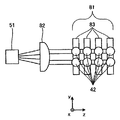
図13は、第5実施形態に係るパターン照射装置80の構成を示す図である。第5実施形態に係る集光部32は、第2のミラー群81と、シリンドリカルレンズ82とを有する。パターン照射装置80は、集光部32が第2のミラー群81とシリンドリカルレンズ82とを有する点で、第4実施形態と異なる。   FIG. 13 is a diagram illustrating a configuration of a pattern irradiation apparatus 80 according to the fifth embodiment. The light collecting unit 32 according to the fifth embodiment includes a second mirror group 81 and a cylindrical lens 82. The pattern irradiation device 80 is different from the fourth embodiment in that the light condensing unit 32 includes a second mirror group 81 and a cylindrical lens 82.

第2のミラー群81は、発光部31から同一方向に出射された複数本の平行光束を反射して、反射拡散板51へと導く。第2のミラー群81は、複数のミラー83を有する。それぞれのミラー83は、レーザダイオード41から出射されてコリメータレンズ42に平行光束とされたレーザ光を、反射拡散板51の方向に反射する。   The second mirror group 81 reflects a plurality of parallel light beams emitted in the same direction from the light emitting unit 31 and guides them to the reflection diffusion plate 51. The second mirror group 81 has a plurality of mirrors 83. Each mirror 83 reflects the laser light emitted from the laser diode 41 and converted into a parallel light beam to the collimator lens 42 in the direction of the reflection diffusion plate 51.

この場合において、複数のミラー83は、反射角によって、複数本の平行光束を光軸に直交する第1方向に集光する。本実施形態においては、複数のミラー83は、複数本の平行光束のx方向の成分が反射拡散板51上で略一点に照射されるように、反射角が設定されている。従って、第2のミラー群81を構成するそれぞれのミラー83は、第1方向の反射角が互いに異なっている。   In this case, the plurality of mirrors 83 condense a plurality of parallel light beams in a first direction orthogonal to the optical axis according to the reflection angle. In the present embodiment, the reflection angles are set so that the plurality of mirrors 83 irradiate substantially one point on the reflection diffusion plate 51 with the x-direction component of the plurality of parallel light beams. Accordingly, the respective mirrors 83 constituting the second mirror group 81 have different reflection angles in the first direction.

シリンドリカルレンズ82は、第2のミラー群81と反射拡散板51との間に設けられる。シリンドリカルレンズ82は、第2のミラー群81から反射拡散板51へと向かう複数本の平行光束を、光軸に直交する方向であって且つ第1方向と直交する第2方向に集光する。   The cylindrical lens 82 is provided between the second mirror group 81 and the reflection diffusion plate 51. The cylindrical lens 82 condenses a plurality of parallel light beams traveling from the second mirror group 81 toward the reflection diffusion plate 51 in a second direction that is orthogonal to the optical axis and orthogonal to the first direction.

図14は、第5実施形態に係る第2のミラー群81およびシリンドリカルレンズ82等の配置の一例を示す図である。本実施形態において、発光部31は、2×4のマトリクス状に配列された8個のレーザダイオード41および8個のコリメータレンズ42を有する。   FIG. 14 is a diagram illustrating an example of the arrangement of the second mirror group 81, the cylindrical lens 82, and the like according to the fifth embodiment. In the present embodiment, the light emitting unit 31 includes eight laser diodes 41 and eight collimator lenses 42 arranged in a 2 × 4 matrix.

また、本実施形態において、第2のミラー群81は、4個のミラー83を有する。4個のミラー83のそれぞれは、y方向に並んだ2個のレーザダイオード41および2個のコリメータレンズ42に対応して配置される。それぞれのミラー83は、対応する2個のコリメータレンズ42から出射される2本の平行光束を反射する。   In the present embodiment, the second mirror group 81 includes four mirrors 83. Each of the four mirrors 83 is arranged corresponding to two laser diodes 41 and two collimator lenses 42 arranged in the y direction. Each mirror 83 reflects two parallel light beams emitted from the corresponding two collimator lenses 42.

なお、第2のミラー群81は、8個のミラー83を有する構成であってもよい。この場合、それぞれのミラー83が、何れか1個のコリメータレンズ42から出射された平行光束を反射する。   Note that the second mirror group 81 may have eight mirrors 83. In this case, each mirror 83 reflects the parallel light beam emitted from any one of the collimator lenses 42.

そして、シリンドリカルレンズ82は、第2のミラー群81から反射拡散板51へと向かう複数本の平行光束を、光軸に直交する方向であって且つ第1方向と直交する第2方向に集光する。本実施形態において、シリンドリカルレンズ82は、複数本の平行光束のy方向の成分が、反射拡散板51上で略一点に照射されるように集光する。   The cylindrical lens 82 condenses a plurality of parallel light beams traveling from the second mirror group 81 toward the reflection diffusion plate 51 in a second direction that is orthogonal to the optical axis and orthogonal to the first direction. To do. In the present embodiment, the cylindrical lens 82 condenses so that components in the y direction of a plurality of parallel light beams are irradiated to substantially one point on the reflection diffusion plate 51.

このようにパターン照射装置80は、第1方向(例えばx方向)には、ミラー83の反射角によって集光するので、レンズによる集光作用を用いていない。従って、パターン照射装置80では、シリンドリカルレンズ82に入射する光束幅が比較的に狭くなり、シリンドリカルレンズ82のレンズ径を小さくすることができる。さらに、パターン照射装置80は、シリンドリカルレンズ82のレンズ径を小さくすることができるので、製造可能なコバ厚を確保しながらシリンドリカルレンズ82の曲率半径を小さくすることができる。このため、パターン照射装置80は、シリンドリカルレンズ82から反射拡散板51までの距離を短くすることができ、この結果、装置構成を小さくすることができる。   As described above, the pattern irradiation device 80 condenses light in the first direction (for example, the x direction) by the reflection angle of the mirror 83, and thus does not use the light condensing action by the lens. Therefore, in the pattern irradiation device 80, the width of the light beam incident on the cylindrical lens 82 is relatively narrow, and the lens diameter of the cylindrical lens 82 can be reduced. Furthermore, since the pattern irradiation apparatus 80 can reduce the lens diameter of the cylindrical lens 82, the radius of curvature of the cylindrical lens 82 can be reduced while ensuring a manufacturable edge thickness. For this reason, the pattern irradiation apparatus 80 can shorten the distance from the cylindrical lens 82 to the reflection diffusion plate 51, and as a result, the apparatus configuration can be reduced.

なお、パターン照射装置80は、シリンドリカルレンズ82に代えて、第1方向(例えばx方向)と第2方向(例えばy方向)とで曲率半径が異なるトロイダルレンズを有してもよい。この場合、第2のミラー群81は、トロイダルレンズの第1方向の集光作用と併せて、複数本の平行光束の第1方向の成分が反射拡散板51上で略一点に照射されるように、反射角が設定される。   Note that the pattern irradiation device 80 may include a toroidal lens having different radii of curvature in the first direction (for example, the x direction) and the second direction (for example, the y direction) instead of the cylindrical lens 82. In this case, the second mirror group 81 is configured to irradiate substantially one point on the reflection diffusion plate 51 with the component in the first direction of the plurality of parallel luminous fluxes, together with the light condensing action in the first direction of the toroidal lens. In addition, the reflection angle is set.

(第6実施形態)
つぎに、第6実施形態に係るパターン照射装置90について説明する。第6実施形態に係るパターン照射装置90は、第4実施形態に係るパターン照射装置70と略同一の機能および構成を有する。略同一の機能および構成を有する部材については、同一の符号を付けて、相違点を除き詳細な説明を省略する。
(Sixth embodiment)
Next, a pattern irradiation apparatus 90 according to the sixth embodiment will be described. The pattern irradiation apparatus 90 according to the sixth embodiment has substantially the same function and configuration as the pattern irradiation apparatus 70 according to the fourth embodiment. Members having substantially the same function and configuration are denoted by the same reference numerals, and detailed description thereof is omitted except for differences.

図15は、第6実施形態に係るパターン照射装置90の構成を示す図である。第6実施形態に係る集光部32は、第3のミラー群91を有する。パターン照射装置90は、集光部32が第3のミラー群91を有する点で、第4実施形態と異なる。   FIG. 15 is a diagram showing a configuration of a pattern irradiation apparatus 90 according to the sixth embodiment. The light collecting unit 32 according to the sixth embodiment includes a third mirror group 91. The pattern irradiation device 90 is different from the fourth embodiment in that the light collecting unit 32 includes a third mirror group 91.

第3のミラー群91は、発光部31から同一方向に出射された複数本の平行光束を反射して、反射拡散板51へと導く。第3のミラー群91は、複数のミラー93を有する。それぞれのミラー93は、レーザダイオード41から出射されてコリメータレンズ42に平行光束とされたレーザ光を、反射拡散板51の方向に反射する。   The third mirror group 91 reflects a plurality of parallel light beams emitted from the light emitting unit 31 in the same direction and guides them to the reflection diffusion plate 51. The third mirror group 91 has a plurality of mirrors 93. Each mirror 93 reflects the laser light emitted from the laser diode 41 and converted into a parallel light beam to the collimator lens 42 in the direction of the reflection diffusion plate 51.

この場合において、複数のミラー93は、反射角によって、複数本の平行光束のそれぞれを集光する。本実施形態においては、複数のミラー93は、複数本の平行光束が反射拡散板51上で略一点に照射されるように、反射角が設定されている。従って、第3のミラー群91を構成するそれぞれのミラー93は、反射角が互いに異なっている。   In this case, the plurality of mirrors 93 collect each of the plurality of parallel light beams according to the reflection angle. In the present embodiment, the reflection angles of the plurality of mirrors 93 are set so that a plurality of parallel light beams are irradiated to substantially one point on the reflection diffusion plate 51. Accordingly, the respective mirrors 93 constituting the third mirror group 91 have different reflection angles.

図16は、第6実施形態に係る第3のミラー群91等の配置の一例を示す図である。本実施形態において、発光部31は、2×4のマトリクス状に配列された8個のレーザダイオード41および8個のコリメータレンズ42を有する。   FIG. 16 is a diagram illustrating an example of the arrangement of the third mirror group 91 and the like according to the sixth embodiment. In the present embodiment, the light emitting unit 31 includes eight laser diodes 41 and eight collimator lenses 42 arranged in a 2 × 4 matrix.

また、本実施形態において、第3のミラー群91は、8個のミラー93を有する。8個のミラー93のそれぞれは、何れか1個のレーザダイオード41および1個のコリメータレンズ42に対応して配置される。それぞれのミラー93は、対応する1個のコリメータレンズ42から出射される1本の平行光束を反射する。そして、それぞれのミラー93は、反射した平行光束が反射拡散板51上の略一点に集光されるように反射角が調整されている。   In the present embodiment, the third mirror group 91 includes eight mirrors 93. Each of the eight mirrors 93 is arranged corresponding to any one laser diode 41 and one collimator lens 42. Each mirror 93 reflects one parallel light beam emitted from the corresponding one collimator lens 42. The reflection angle of each mirror 93 is adjusted so that the reflected parallel light beam is condensed at substantially one point on the reflection diffusion plate 51.

このようにパターン照射装置90は、第3のミラー群91により光束を反射拡散板51上に集光する。従って、パターン照射装置90は、反射拡散板51上に光束を集光するためのレンズを備えなくてよいので、構成が簡易となる。さらに、レンズで集光する場合、レンズから反射拡散板51までの距離に、焦点距離の下限による制限がある。しかし、パターン照射装置90は、第3のミラー群91を構成するミラー93の傾きを調整すればよいので、このような距離の制限が無く配置をコンパクトにすることができる。   As described above, the pattern irradiation device 90 condenses the light flux on the reflection diffusion plate 51 by the third mirror group 91. Therefore, the pattern irradiating device 90 does not need to include a lens for condensing the light flux on the reflection diffusion plate 51, and thus the configuration becomes simple. Furthermore, when condensing with a lens, the distance from the lens to the reflection diffusion plate 51 is limited by the lower limit of the focal length. However, since the pattern irradiation device 90 only needs to adjust the inclination of the mirror 93 constituting the third mirror group 91, there is no such limitation on the distance, and the arrangement can be made compact.

(第7実施形態)
つぎに、第7実施形態に係るパターン照射装置110について説明する。第7実施形態に係るパターン照射装置110は、第1実施形態に係るパターン照射装置20と略同一の機能および構成を有する。略同一の機能および構成を有する部材については、同一の符号を付けて、相違点を除き詳細な説明を省略する。
(Seventh embodiment)
Next, a pattern irradiation apparatus 110 according to the seventh embodiment will be described. The pattern irradiation apparatus 110 according to the seventh embodiment has substantially the same function and configuration as the pattern irradiation apparatus 20 according to the first embodiment. Members having substantially the same function and configuration are denoted by the same reference numerals, and detailed description thereof is omitted except for differences.

図17は、第7実施形態に係るパターン照射装置110の構成を示す図である。パターン照射装置110は、発光部31と、集光部32と、透過蛍光部111と、ライトトンネル34と、透過拡散板33bと、画像形成部35と、照射光学系36とを備える。パターン照射装置110は、透過拡散板33aに代えて透過蛍光部111を備える点で、第1実施形態と異なる。   FIG. 17 is a diagram illustrating a configuration of a pattern irradiation apparatus 110 according to the seventh embodiment. The pattern irradiation apparatus 110 includes a light emitting unit 31, a light collecting unit 32, a transmission fluorescent unit 111, a light tunnel 34, a transmission diffusion plate 33b, an image forming unit 35, and an irradiation optical system 36. The pattern irradiation apparatus 110 is different from the first embodiment in that a transmission fluorescent part 111 is provided instead of the transmission diffusion plate 33a.

集光部32は、発光部31から出射された光を透過蛍光部111上に集光する。本実施形態においては、集光部32は、複数本のレーザ光を透過蛍光部111上の略一点に集光する。   The condensing unit 32 condenses the light emitted from the light emitting unit 31 on the transmission fluorescent unit 111. In the present embodiment, the condensing unit 32 condenses a plurality of laser beams at approximately one point on the transmission fluorescent unit 111.

透過蛍光部111は、入射した光を励起光として蛍光を発する透過型の蛍光部である。透過蛍光部111は、集光部32により集光された複数本のレーザ光を入射して、入射した光を励起光として蛍光を発する。透過蛍光部111は、発生した蛍光を、集光部32とは反対側に配置されたライトトンネル34へと出射する。   The transmission fluorescent part 111 is a transmission type fluorescent part that emits fluorescence using incident light as excitation light. The transmitted fluorescent part 111 receives a plurality of laser beams collected by the condenser 32 and emits fluorescence using the incident light as excitation light. The transmission fluorescent part 111 emits the generated fluorescence to the light tunnel 34 disposed on the side opposite to the light collecting part 32.

ライトトンネル34は、透過蛍光部111により発光された蛍光を入射し、照度分布を均一化して出射する。ライトトンネル34は、透過蛍光部111から発光された蛍光の出射角と同一の角度の光を出射することができる。   The light tunnel 34 enters the fluorescent light emitted from the transmission fluorescent part 111 and emits it with a uniform illuminance distribution. The light tunnel 34 can emit light having the same angle as the emission angle of the fluorescence emitted from the transmission fluorescent part 111.

透過蛍光部111は、一例として、ガラス板等の透明の基板と、基板上に設けられた蛍光体とを有する。これにより、透過蛍光部111は、励起光の入射面とは反対側の面から蛍光を出射することができる。   As an example, the transmission fluorescent part 111 includes a transparent substrate such as a glass plate and a phosphor provided on the substrate. Thereby, the transmission fluorescence part 111 can radiate | emit fluorescence from the surface on the opposite side to the incident surface of excitation light.

また、透過蛍光部111は、一例として、蛍光体セラミックスであってもよい。蛍光体セラミックスは、蛍光体を任意の形状(例えば、薄板状)に成形して加熱した焼結体である。なお、透過蛍光部111は、このようなものに限らず、発光部31から発光された光を励起光として蛍光を発し、励起光の入射面とは反対側の面から蛍光を出射する構成であれば、どのようなものであってもよい。   Further, the transmission fluorescent part 111 may be a phosphor ceramic as an example. The phosphor ceramic is a sintered body obtained by forming a phosphor into an arbitrary shape (for example, a thin plate shape) and heating it. The transmission fluorescent part 111 is not limited to this, and emits fluorescence using the light emitted from the light emitting part 31 as excitation light, and emits fluorescence from a surface opposite to the incident surface of the excitation light. Anything is acceptable.

本実施形態においては、発光部31は、青色のレーザ光を発生する。そして、透過蛍光部111は、青色のレーザ光を励起光として、黄色の光を発する。青色のレーザ光を発光するダイオードは、比較的に高出力であり且つ安価である。従って、発光部31が青色のレーザ光を発生することにより、パターン照射装置110は、安価な構成で、高出力の光を対象物11に照射することができる。従って、パターン照射装置110は、対象物11の表面が黒色等であっても、安価な構成で、精度良く距離測定をさせることができる。   In the present embodiment, the light emitting unit 31 generates blue laser light. Then, the transmission fluorescent part 111 emits yellow light using blue laser light as excitation light. A diode emitting blue laser light has a relatively high output and is inexpensive. Therefore, when the light emitting unit 31 generates blue laser light, the pattern irradiation device 110 can irradiate the object 11 with high output light with an inexpensive configuration. Therefore, even if the surface of the object 11 is black or the like, the pattern irradiation device 110 can accurately measure the distance with an inexpensive configuration.

なお、発光部31から発せられる光は、青色に限らず、他の波長の光(例えば紫外光、可視光以外の光)であってもよい。また、透過蛍光部111は、黄色に限らず、どのような波長の光(例えば、赤色、緑色、青色または白色等)の蛍光を発してもよい。   The light emitted from the light emitting unit 31 is not limited to blue, but may be light of other wavelengths (for example, light other than ultraviolet light and visible light). Further, the transmission fluorescent part 111 is not limited to yellow, and may emit fluorescence of light of any wavelength (for example, red, green, blue, or white).

また、透過蛍光部111は、コヒーレントな光を励起光として、インコヒーレントな蛍光を発する。従って、透過蛍光部111は、スペックルノイズを含まない均一な光を発することができる。これにより、本実施形態に係るパターン照射装置110によれば、スペックルノイズを除去した画像パターンを対象物11に照射することができる。   In addition, the transmission fluorescence unit 111 emits incoherent fluorescence using the coherent light as excitation light. Therefore, the transmission fluorescent part 111 can emit uniform light that does not include speckle noise. Thereby, according to the pattern irradiation apparatus 110 which concerns on this embodiment, the target object 11 can be irradiated with the image pattern from which the speckle noise was removed.

また、透過蛍光部111は、リレー光学系等を介さずに、ライトトンネル34の直前に配置されている。蛍光体から発せられる光は一般にランバート分布であり、光の広がり角が大きいので、距離が開くとライトトンネル34の外部へと漏れてしまう虞がある。そこで、透過蛍光部111とライトトンネル34の間の光学的な距離は短いことが好ましい。かかる構成によりパターン照射装置110は、蛍光がライトトンネル34の外部へと漏れてしまうことを防止することができる。よって、パターン照射装置110は、光の伝達の効率を高め、出力するエネルギーを大きくすることができる。   Further, the transmission fluorescent part 111 is arranged immediately before the light tunnel 34 without using a relay optical system or the like. The light emitted from the phosphor generally has a Lambertian distribution and has a large light spread angle. Therefore, when the distance increases, there is a possibility that the light will leak outside the light tunnel 34. Therefore, it is preferable that the optical distance between the transmission fluorescent part 111 and the light tunnel 34 is short. With this configuration, the pattern irradiation device 110 can prevent the fluorescence from leaking outside the light tunnel 34. Therefore, the pattern irradiation apparatus 110 can increase the efficiency of light transmission and increase the output energy.

また、集光部32は、発光部31から出射された複数本のレーザ光を透過蛍光部111上に集光する。従って、発光部31が有するレーザダイオード41の個数を増加させても、面積が比較的に小さい透過蛍光部111上に光を集光することができる。従って、パターン照射装置110は、蛍光体を小さくしてコストを抑えながら、出力するエネルギーを大きくすることができる。   The condensing unit 32 condenses a plurality of laser beams emitted from the light emitting unit 31 on the transmission fluorescent unit 111. Therefore, even if the number of laser diodes 41 included in the light emitting unit 31 is increased, light can be collected on the transmission fluorescent unit 111 having a relatively small area. Therefore, the pattern irradiation apparatus 110 can increase the output energy while reducing the size of the phosphor and reducing the cost.

以上のように、本実施形態に係るパターン照射装置110によれば、画像パターンからスペックルノイズを除去し、さらに、サイズおよびコストを小さくすることができる。   As described above, according to the pattern irradiation apparatus 110 according to the present embodiment, speckle noise can be removed from the image pattern, and the size and cost can be reduced.

なお、本実施形態に係るパターン照射装置110は、ライトトンネル34に代えて、図9に示すテーパライトトンネル61を備える構成であってもよい。これにより、本実施形態に係るパターン照射装置110は、第3実施形態と同様の効果を得ることができる。   Note that the pattern irradiation apparatus 110 according to the present embodiment may include a tapered light tunnel 61 shown in FIG. 9 instead of the light tunnel 34. Thereby, the pattern irradiation apparatus 110 which concerns on this embodiment can acquire the effect similar to 3rd Embodiment.

また、本実施形態に係るパターン照射装置110は、図10に示したプリズム71またはミラーを備える構成であってもよい。また、本実施形態に係るパターン照射装置110は、集光部32が図11、図12(a)または図12(b)に示した構成であってもよい。これにより、本実施形態に係るパターン照射装置110は、第4実施形態と同様の効果を得ることができる。   Moreover, the pattern irradiation apparatus 110 which concerns on this embodiment may be the structure provided with the prism 71 or the mirror shown in FIG. Moreover, the pattern irradiation apparatus 110 which concerns on this embodiment may have the structure which the condensing part 32 showed to FIG. 11, FIG. 12 (a) or FIG.12 (b). Thereby, the pattern irradiation apparatus 110 which concerns on this embodiment can acquire the effect similar to 4th Embodiment.

また、本実施形態に係るパターン照射装置110は、集光部32の構成が図13および図14に示した光学構成であってもよい。これにより、本実施形態に係るパターン照射装置110は、第5実施形態と同様の効果を得ることができる。   Further, in the pattern irradiation apparatus 110 according to the present embodiment, the configuration of the light collecting unit 32 may be the optical configuration illustrated in FIGS. 13 and 14. Thereby, the pattern irradiation apparatus 110 which concerns on this embodiment can acquire the effect similar to 5th Embodiment.

また、本実施形態に係るパターン照射装置110は、集光部32の構成が図15および図16に示した光学構成であってもよい。これにより、本実施形態に係るパターン照射装置110は、第6実施形態と同様の効果を得ることができる。
なお、本実施例では、パターン照射装置110は、透過蛍光部111を有している。蛍光体からはランバート分布の光が発光するため、光源にレーザを用いてライトトンネル34の前に透過拡散板33aなどの拡散部を置く構成よりも、ライトトンネルに入射する光の広がり角は大きくなる。しかしながら、図3(c)で説明したように、ライトトンネル34の出力口46における各像高での広がり角度は、入力口45における入射角度範囲の一部である。よって、本実施例においてもライトトンネル34の+x方向側に透過拡散板33bを設けることで照射光学系内の各光学部材の劣化を防ぐことができる。この効果は以下の蛍光体を用いた各実施例でも同様に得ることが出来る。
Further, in the pattern irradiation apparatus 110 according to the present embodiment, the configuration of the light collecting unit 32 may be the optical configuration illustrated in FIGS. 15 and 16. Thereby, the pattern irradiation apparatus 110 which concerns on this embodiment can acquire the effect similar to 6th Embodiment.
In the present embodiment, the pattern irradiation device 110 has a transmission fluorescent part 111. Since light of Lambertian distribution is emitted from the phosphor, the spread angle of the light incident on the light tunnel is larger than the configuration in which a diffusing portion such as a transmission diffusion plate 33a is placed in front of the light tunnel 34 using a laser as a light source. Become. However, as described in FIG. 3C, the spread angle at each image height at the output port 46 of the light tunnel 34 is a part of the incident angle range at the input port 45. Therefore, also in the present embodiment, by providing the transmission diffusion plate 33b on the + x direction side of the light tunnel 34, it is possible to prevent deterioration of each optical member in the irradiation optical system. This effect can be obtained in the same manner in each embodiment using the following phosphors.

(第8実施形態)
つぎに、第8実施形態に係るパターン照射装置120について説明する。第8実施形態に係るパターン照射装置120は、第7実施形態に係るパターン照射装置110と略同一の機能および構成を有する。略同一の機能および構成を有する部材については、同一の符号を付けて、相違点を除き詳細な説明を省略する。
(Eighth embodiment)
Next, a pattern irradiation apparatus 120 according to the eighth embodiment will be described. The pattern irradiation apparatus 120 according to the eighth embodiment has substantially the same function and configuration as the pattern irradiation apparatus 110 according to the seventh embodiment. Members having substantially the same function and configuration are denoted by the same reference numerals, and detailed description thereof is omitted except for differences.

図18は、第8実施形態に係るパターン照射装置120の構成を示す図である。パターン照射装置120は、発光部31と、集光部32と、可動透過蛍光部121と、第1の駆動部122と、ライトトンネル34と、透過拡散板33bと、画像形成部35と、照射光学系36とを備える。
パターン照射装置120は、透過蛍光部111に代えて、可動透過蛍光部121および第1の駆動部122を備える点で、第7実施形態と異なる。
FIG. 18 is a diagram showing a configuration of a pattern irradiation apparatus 120 according to the eighth embodiment. The pattern irradiation device 120 includes a light emitting unit 31, a light collecting unit 32, a movable transmission fluorescent unit 121, a first driving unit 122, a light tunnel 34, a transmission diffusion plate 33b, an image forming unit 35, and an irradiation. And an optical system 36.
The pattern irradiation apparatus 120 is different from the seventh embodiment in that it includes a movable transmissive fluorescent part 121 and a first driving part 122 instead of the transmissive fluorescent part 111.

可動透過蛍光部121は、光が照射される部分を変更させることが可能な透過型の蛍光部である。可動透過蛍光部121は、集光部32により集光された複数本のレーザ光を入射して、入射した光を励起光として蛍光を発する。可動透過蛍光部121は、発生した蛍光を、集光部32とは反対側に配置されたライトトンネル34へと出射する。第1の駆動部122は、可動透過蛍光部121における光が照射される部分を変更させる。   The movable transmissive fluorescent part 121 is a transmissive fluorescent part capable of changing a portion irradiated with light. The movable transmissive fluorescent unit 121 receives a plurality of laser beams condensed by the condensing unit 32 and emits fluorescence using the incident light as excitation light. The movable transmission fluorescent part 121 emits the generated fluorescence to the light tunnel 34 disposed on the side opposite to the light collecting part 32. The first drive unit 122 changes the portion of the movable transmission fluorescent unit 121 that is irradiated with light.

図19は、可動透過蛍光部121および第1の駆動部122の一例を示す図である。可動透過蛍光部121は、一例として、基板123と、蛍光体124とを含む。基板123は、透明な円板状の薄板であり、中心軸を中心として回転可能である。蛍光体124は、基板123の周縁部分にリング状に設けられる。蛍光体124は、一部分に、集光部32により集光された複数本のレーザ光を入射して、入射した光を励起光として蛍光を発する。   FIG. 19 is a diagram illustrating an example of the movable transmission fluorescent unit 121 and the first driving unit 122. The movable transmissive fluorescent part 121 includes a substrate 123 and a phosphor 124 as an example. The substrate 123 is a transparent disk-shaped thin plate, and is rotatable around the central axis. The phosphor 124 is provided in a ring shape on the periphery of the substrate 123. A part of the phosphor 124 enters a plurality of laser beams condensed by the condensing unit 32 and emits fluorescence using the incident light as excitation light.

第1の駆動部122は、基板123の中心軸を中心に、可動透過蛍光部121を回転駆動する。これにより、第1の駆動部122は、リング状の蛍光体124における、集光部32により集光されたレーザ光が照射される部分を変更させることができる。   The first drive unit 122 rotates the movable transmission fluorescent unit 121 around the central axis of the substrate 123. Thereby, the 1st drive part 122 can change the part to which the laser beam condensed by the condensing part 32 in the ring-shaped fluorescent substance 124 is irradiated.

このように第8実施形態に係るパターン照射装置120は、可動透過蛍光部121における光が照射される部分を変更させることができる。これにより、第8実施形態に係るパターン照射装置120は、可動透過蛍光部121の同一の部分にレーザ光を長時間集中して照射することによる劣化を防止することができる。   As described above, the pattern irradiation device 120 according to the eighth embodiment can change the portion of the movable transmission fluorescent portion 121 that is irradiated with light. Thereby, the pattern irradiation apparatus 120 according to the eighth embodiment can prevent deterioration caused by irradiating the same portion of the movable transmission fluorescent part 121 with the laser beam concentrated for a long time.

なお、可動透過蛍光部121は、リング状の蛍光体124が回転可能に設けられた構成でなくてもよい。例えば、可動透過蛍光部121は、長尺状の蛍光体124が、長手方向に沿って往復移動可能に設けられた構成であってもよい。また、可動透過蛍光部121は、多角形状の蛍光体124または長円状の蛍光体124が設けられた構成であってもよい。また、可動透過蛍光部121は、基板123および蛍光体124を含む構成に代えて、蛍光体セラミックスを用いた構成であってもよい。   The movable transmission fluorescent part 121 may not have a configuration in which the ring-shaped phosphor 124 is rotatably provided. For example, the movable transmission fluorescent part 121 may have a configuration in which a long phosphor 124 is provided so as to be reciprocally movable along the longitudinal direction. Further, the movable transmission fluorescent part 121 may have a configuration in which a polygonal fluorescent substance 124 or an elliptical fluorescent substance 124 is provided. In addition, the movable transmission fluorescent part 121 may be configured using phosphor ceramics instead of the configuration including the substrate 123 and the phosphor 124.

(第9実施形態)
つぎに、第9実施形態に係るパターン照射装置130について説明する。第9実施形態に係るパターン照射装置130は、第7実施形態に係るパターン照射装置110と略同一の機能および構成を有する。略同一の機能および構成を有する部材については、同一の符号を付けて、相違点を除き詳細な説明を省略する。
(Ninth embodiment)
Next, a pattern irradiation apparatus 130 according to the ninth embodiment will be described. The pattern irradiation apparatus 130 according to the ninth embodiment has substantially the same function and configuration as the pattern irradiation apparatus 110 according to the seventh embodiment. Members having substantially the same function and configuration are denoted by the same reference numerals, and detailed description thereof is omitted except for differences.

図20は、第9実施形態に係るパターン照射装置130の構成を示す図である。パターン照射装置130は、発光部31と、集光部32と、反射蛍光部131と、ライトトンネル34と、透過拡散板33bと、画像形成部35と、照射光学系36とを備える。パターン照射装置130は、透過蛍光部111に代えて反射蛍光部131を備える点で、第7実施形態と異なる。   FIG. 20 is a diagram illustrating a configuration of a pattern irradiation apparatus 130 according to the ninth embodiment. The pattern irradiation device 130 includes a light emitting unit 31, a light collecting unit 32, a reflection fluorescent unit 131, a light tunnel 34, a transmission diffusion plate 33 b, an image forming unit 35, and an irradiation optical system 36. The pattern irradiation device 130 is different from the seventh embodiment in that a reflective fluorescent unit 131 is provided instead of the transmitted fluorescent unit 111.

集光部32は、発光部31から出射された光を反射蛍光部131上に集光する。本実施形態においては、集光部32は、複数本のレーザ光を反射蛍光部131上の略一点に集光する。   The condensing unit 32 condenses the light emitted from the light emitting unit 31 on the reflection fluorescent unit 131. In the present embodiment, the condensing unit 32 condenses a plurality of laser beams at approximately one point on the reflective fluorescent unit 131.

反射蛍光部131は、入射した光を励起光として蛍光を発する反射型の蛍光部である。反射蛍光部131は、集光部32により集光された複数本のレーザ光を入射して、入射した光を励起光として蛍光を発する。反射蛍光部131は、発生した蛍光を、集光部32と同一側の面に配置されたライトトンネル34へと出射する。反射蛍光部131は、励起光が入射してきた面側に蛍光を発する。なお、反射蛍光部131は、励起光が入射してきた面側に蛍光を発する点において、透過蛍光部111と異なるが、他の機能および効果について透過蛍光部111と同一である。   The reflected fluorescent part 131 is a reflective fluorescent part that emits fluorescence using incident light as excitation light. The reflected fluorescent part 131 receives a plurality of laser beams collected by the condenser 32 and emits fluorescence using the incident light as excitation light. The reflected fluorescent part 131 emits the generated fluorescence to the light tunnel 34 arranged on the same side as the light collecting part 32. The reflected fluorescent part 131 emits fluorescence on the surface side on which the excitation light has entered. The reflected fluorescent part 131 is different from the transmitted fluorescent part 111 in that it emits fluorescence toward the surface on which the excitation light is incident, but is the same as the transmitted fluorescent part 111 in other functions and effects.

ライトトンネル34は、反射蛍光部131により発光された蛍光を入射し、照度分布を均一化して出射する。ライトトンネル34は、反射蛍光部131から発光された蛍光の出射角と同一の角度の光を出射することができる。   The light tunnel 34 enters the fluorescent light emitted by the reflective fluorescent part 131 and emits it with a uniform illuminance distribution. The light tunnel 34 can emit light having the same angle as the emission angle of the fluorescence emitted from the reflection fluorescent part 131.

反射蛍光部131は、一例として、反射基板と、反射基板上に設けられた蛍光体とを有する。発光部31から出射された光は、蛍光体が設けられた側の面から入射される。これにより、反射蛍光部131は、発光した蛍光を発光部31側に反射することができる。反射基板は、レーザ光の波長および蛍光体が発する光の波長を含む帯域の光を反射する。反射基板は、一例として、誘電体多層膜または金属膜等の反射コーティング膜が表面に形成されていてもよい。これにより、反射基板は、反射率を高くすることができる。   As an example, the reflective fluorescent part 131 includes a reflective substrate and a phosphor provided on the reflective substrate. The light emitted from the light emitting unit 31 is incident from the surface on which the phosphor is provided. Thereby, the reflection fluorescence part 131 can reflect the emitted fluorescence to the light emission part 31 side. The reflective substrate reflects light in a band including the wavelength of the laser light and the wavelength of the light emitted from the phosphor. As an example, the reflective substrate may have a reflective coating film such as a dielectric multilayer film or a metal film formed on the surface thereof. Thereby, the reflective substrate can increase the reflectance.

また、反射蛍光部131は、一例として、蛍光体セラミックスであってもよい。この場合、反射蛍光部131は、光が入射する面とは反対側の面(発光部31側の面とは反対側の面)に反射コーティング膜が形成される。これにより、反射蛍光部131は、発光した蛍光を発光部31側に反射することができる。なお、反射蛍光部131は、このようなものに限らず、発光部31から発光された光を励起光として蛍光を発し、励起光の入射面側に蛍光を出射する構成であれば、どのようなものであってもよい。   Moreover, the reflective fluorescent part 131 may be phosphor ceramics as an example. In this case, in the reflective fluorescent part 131, a reflective coating film is formed on the surface opposite to the light incident surface (surface opposite to the light emitting unit 31 side). Thereby, the reflection fluorescence part 131 can reflect the emitted fluorescence to the light emission part 31 side. The reflection fluorescent part 131 is not limited to this, and any configuration may be used as long as it emits fluorescence using the light emitted from the light emitting part 31 as excitation light and emits fluorescence toward the incident surface side of the excitation light. It may be anything.

図21は、反射蛍光部131を側面側から見た図である。反射蛍光部131は、入射したレーザ光を励起光として蛍光を発生する。この場合、反射蛍光部131は、蛍光体の表面に沿った方向を0°(360°)および180°とした場合、周囲360°の方向に蛍光を発する。蛍光体は、レーザ光の入射方向に対して45°に傾けて配置される。従って、レーザ光が入射される面側(0°から180°の範囲の方向側)に発光された蛍光は、大部分がライトトンネル34に導かれる。   FIG. 21 is a view of the reflective fluorescent part 131 as viewed from the side. The reflected fluorescent part 131 generates fluorescence using the incident laser light as excitation light. In this case, the reflection fluorescent part 131 emits fluorescence in the direction of 360 ° when the directions along the surface of the phosphor are 0 ° (360 °) and 180 °. The phosphor is disposed at an angle of 45 ° with respect to the incident direction of the laser beam. Therefore, most of the fluorescence emitted on the surface side on which the laser light is incident (the direction side in the range of 0 ° to 180 °) is guided to the light tunnel 34.

反対に、レーザ光が入射される面とは反対側(180°から360°の範囲の方向側)に発光された蛍光は、反射基板で反射され、大部分がライトトンネル34に導かれる。また、蛍光体に入射したが、蛍光に変換されなかった励起光(レーザ光)も反射基板で反射し、再度、蛍光に照射されて蛍光に変換され、ライトトンネル34に導かれる。よって、反射蛍光部131は、レーザ光を効率良く蛍光に変換することができる。   On the other hand, the fluorescence emitted on the side opposite to the surface on which the laser beam is incident (the direction side in the range of 180 ° to 360 °) is reflected by the reflecting substrate, and most of the fluorescence is guided to the light tunnel 34. The excitation light (laser light) that has entered the phosphor but has not been converted to fluorescence is also reflected by the reflective substrate, is again irradiated with fluorescence, converted to fluorescence, and guided to the light tunnel 34. Therefore, the reflection fluorescence part 131 can convert a laser beam into fluorescence efficiently.

以上のように、本実施形態に係るパターン照射装置130によれば、画像パターンからスペックルノイズを低減し、さらに、サイズおよびコストを小さくすることができる。また、本実施形態に係るパターン照射装置130によれば、高い光出力を得ることができる。また、さらに、本実施形態に係るパターン照射装置130は、第2実施形態と同様に、反射蛍光部131が脱落または破損したときのレーザ光の出射防止機構を簡単な構成で実現することができる。   As described above, according to the pattern irradiation apparatus 130 according to the present embodiment, speckle noise can be reduced from the image pattern, and the size and cost can be further reduced. Moreover, according to the pattern irradiation apparatus 130 which concerns on this embodiment, a high light output can be obtained. Furthermore, similarly to the second embodiment, the pattern irradiation apparatus 130 according to the present embodiment can realize a laser beam emission preventing mechanism when the reflected fluorescent part 131 is dropped or damaged with a simple configuration. .

なお、本実施形態に係るパターン照射装置130は、ライトトンネル34に代えて、図9に示すテーパライトトンネル61を備える構成であってもよい。これにより、本実施形態に係るパターン照射装置130は、第3実施形態と同様の効果を得ることができる。   Note that the pattern irradiation apparatus 130 according to the present embodiment may be configured to include the tapered light tunnel 61 shown in FIG. 9 instead of the light tunnel 34. Thereby, the pattern irradiation apparatus 130 which concerns on this embodiment can acquire the effect similar to 3rd Embodiment.

また、本実施形態に係るパターン照射装置130は、図10に示したプリズム71またはミラーを備える構成であってもよい。また、本実施形態に係るパターン照射装置130は、集光部32が図11、図12(a)または図12(b)に示した構成であってもよい。これにより、本実施形態に係るパターン照射装置130は、第4実施形態と同様の効果を得ることができる。   Further, the pattern irradiation apparatus 130 according to the present embodiment may be configured to include the prism 71 or the mirror illustrated in FIG. Moreover, the pattern irradiation apparatus 130 which concerns on this embodiment may have the structure which the condensing part 32 showed to FIG. 11, FIG. 12 (a) or FIG.12 (b). Thereby, the pattern irradiation apparatus 130 which concerns on this embodiment can acquire the effect similar to 4th Embodiment.

特に、集光部32が図12(b)に示した構成である場合、反射蛍光部131上に集光される光の入射角が小さくなる。これにより、レンズ73と反射蛍光部131の距離を短くしても、レンズ73から出射された光線は、テーパライトトンネル61または反射蛍光部131の側面によりけられることなく、効率良く反射蛍光部131の表面に導かれる。よって、集光部32が図12(b)に示した構成である場合、パターン照射装置130は、レンズ73と反射蛍光部131の間の距離を短くでき、装置を小型化することができる。さらに、パターン照射装置130は、装置を小型化することに伴い、励起光の反射蛍光部131に対する照射位置への公差によるずれが小さくなる。この結果、パターン照射装置130は、反射蛍光部131上の発光面積を小さくすることができる。従って、パターン照射装置130によれば、蛍光を効率良くテーパライトトンネル61に導いて、高出力化を図ることができる。   In particular, when the condensing part 32 has the configuration shown in FIG. 12B, the incident angle of the light condensed on the reflective fluorescent part 131 becomes small. As a result, even if the distance between the lens 73 and the reflective fluorescent part 131 is shortened, the light beam emitted from the lens 73 is not scattered by the side surface of the tapered light tunnel 61 or the reflective fluorescent part 131 and is efficiently reflected. Led to the surface. Therefore, when the condensing part 32 is the structure shown in FIG.12 (b), the pattern irradiation apparatus 130 can shorten the distance between the lens 73 and the reflective fluorescence part 131, and can reduce an apparatus size. Furthermore, as the pattern irradiation apparatus 130 is downsized, the deviation due to the tolerance of the excitation light to the irradiation position of the reflected fluorescent part 131 is reduced. As a result, the pattern irradiation device 130 can reduce the light emission area on the reflective fluorescent part 131. Therefore, according to the pattern irradiation device 130, it is possible to efficiently guide the fluorescence to the tapered light tunnel 61 and increase the output.

また、本実施形態に係るパターン照射装置130は、集光部32の構成が図13および図14に示した光学構成であってもよい。これにより、本実施形態に係るパターン照射装置130は、第5実施形態と同様の効果を得ることができる。   Further, in the pattern irradiation apparatus 130 according to the present embodiment, the configuration of the light collecting unit 32 may be the optical configuration illustrated in FIGS. 13 and 14. Thereby, the pattern irradiation apparatus 130 which concerns on this embodiment can acquire the effect similar to 5th Embodiment.

また、本実施形態に係るパターン照射装置130は、集光部32の構成が図15および図16に示した光学構成であってもよい。これにより、本実施形態に係るパターン照射装置130は、第6実施形態と同様の効果を得ることができる。   In the pattern irradiation apparatus 130 according to the present embodiment, the configuration of the light collecting unit 32 may be the optical configuration illustrated in FIGS. 15 and 16. Thereby, the pattern irradiation apparatus 130 which concerns on this embodiment can acquire the effect similar to 6th Embodiment.

(第10実施形態)
つぎに、第10実施形態に係るパターン照射装置140について説明する。第10実施形態に係るパターン照射装置140は、第9実施形態に係るパターン照射装置130と略同一の機能および構成を有する。略同一の機能および構成を有する部材については、同一の符号を付けて、相違点を除き詳細な説明を省略する。
(10th Embodiment)
Next, a pattern irradiation apparatus 140 according to the tenth embodiment will be described. The pattern irradiation apparatus 140 according to the tenth embodiment has substantially the same function and configuration as the pattern irradiation apparatus 130 according to the ninth embodiment. Members having substantially the same function and configuration are denoted by the same reference numerals, and detailed description thereof is omitted except for differences.

図22は、第10実施形態に係るパターン照射装置140の構成を示す図である。パターン照射装置140は、発光部31と、集光部32と、可動反射蛍光部141と、第2の駆動部142と、ライトトンネル34と、透過拡散板33bと、画像形成部35と、照射光学系36とを備える。パターン照射装置140は、反射蛍光部131に代えて、可動反射蛍光部141および第2の駆動部142を備える点で、第9実施形態と異なる。   FIG. 22 is a diagram illustrating a configuration of a pattern irradiation apparatus 140 according to the tenth embodiment. The pattern irradiation device 140 includes a light emitting unit 31, a light collecting unit 32, a movable reflective fluorescent unit 141, a second driving unit 142, a light tunnel 34, a transmission diffusion plate 33b, an image forming unit 35, and an irradiation. And an optical system 36. The pattern irradiation device 140 is different from the ninth embodiment in that it includes a movable reflective fluorescent part 141 and a second drive part 142 instead of the reflective fluorescent part 131.

可動反射蛍光部141は、光が照射される部分を変更することが可能な反射型の蛍光部である。可動反射蛍光部141は、集光部32により集光された複数本のレーザ光を入射して、入射した光を励起光として蛍光を発する。可動反射蛍光部141は、発生した蛍光を、集光部32側に配置されたライトトンネル34へと出射する。第2の駆動部142は、可動反射蛍光部141における光が照射される部分を変更させる。   The movable reflective fluorescent part 141 is a reflective fluorescent part capable of changing the part irradiated with light. The movable reflection fluorescent unit 141 receives a plurality of laser beams condensed by the condensing unit 32 and emits fluorescence using the incident light as excitation light. The movable reflection fluorescent part 141 emits the generated fluorescence to the light tunnel 34 arranged on the light collecting part 32 side. The second drive unit 142 changes the portion of the movable reflection fluorescent unit 141 that is irradiated with light.

可動反射蛍光部141は、図19に示した構成と略同一であってよい。具体的には、可動反射蛍光部141は、一例として、基板123と、蛍光体124とを含む。この場合、基板123は、光を反射する部材であって、例えば、誘電体多層膜または金属膜等の反射コーティング膜が表面に形成されている。蛍光体124は、基板123の周縁部分にリング状に設けられ、基板123とは反対側の面側から光が入射される。   The movable reflective fluorescent part 141 may be substantially the same as the configuration shown in FIG. Specifically, the movable reflective fluorescent part 141 includes a substrate 123 and a phosphor 124 as an example. In this case, the substrate 123 is a member that reflects light, and a reflective coating film such as a dielectric multilayer film or a metal film is formed on the surface thereof. The phosphor 124 is provided in a ring shape at the peripheral portion of the substrate 123, and light is incident from the surface side opposite to the substrate 123.

なお、可動反射蛍光部141も、リング状の蛍光体124が回転可能に設けられた構成に限らない。可動反射蛍光部141は、例えば、長尺状の蛍光体124が、長手方向に沿って往復移動可能に設けられた構成であってもよい。また、可動反射蛍光部141は、多角形状の蛍光体124または長円状の蛍光体124が設けられた構成であってもよい。また、可動反射蛍光部141は、基板123および蛍光体124を含む構成に代えて、蛍光体セラミックスを用いた構成であってもよい。この場合、可動反射蛍光部141は、光が入射する面とは反対側の面(発光部31とは反対側の面)に反射コーティング膜が形成される。   Note that the movable reflecting fluorescent portion 141 is not limited to the configuration in which the ring-shaped phosphor 124 is rotatably provided. For example, the movable reflective fluorescent part 141 may have a configuration in which a long phosphor 124 is provided so as to be capable of reciprocating along the longitudinal direction. Further, the movable reflective fluorescent part 141 may be configured such that a polygonal fluorescent substance 124 or an elliptical fluorescent substance 124 is provided. Further, the movable reflective fluorescent portion 141 may be configured using fluorescent ceramics instead of the configuration including the substrate 123 and the fluorescent material 124. In this case, the movable reflective fluorescent portion 141 has a reflective coating film formed on the surface opposite to the surface on which light is incident (the surface opposite to the light emitting portion 31).

このように第10実施形態に係るパターン照射装置140は、可動反射蛍光部141における光が照射される部分を変更することができる。これにより、第10実施形態に係るパターン照射装置140は、高い光出力を得ることができるとともに、可動反射蛍光部141の同一の部分にレーザ光を長時間集中して照射することによる劣化を防止することができる。   As described above, the pattern irradiation apparatus 140 according to the tenth embodiment can change the portion irradiated with light in the movable reflective fluorescent portion 141. Thereby, the pattern irradiation apparatus 140 according to the tenth embodiment can obtain a high light output, and prevents deterioration caused by irradiating the same portion of the movable reflective fluorescent part 141 with laser light concentrated for a long time. can do.

(第11実施形態)
つぎに、第11実施形態に係るパターン照射装置150について説明する。第11実施形態に係るパターン照射装置150は、第4実施形態に係るパターン照射装置70と略同一の機能および構成を有する。略同一の機能および構成を有する部材については、同一の符号を付けて、相違点を除き詳細な説明を省略する。
(Eleventh embodiment)
Next, a pattern irradiation apparatus 150 according to the eleventh embodiment will be described. The pattern irradiation apparatus 150 according to the eleventh embodiment has substantially the same function and configuration as the pattern irradiation apparatus 70 according to the fourth embodiment. Members having substantially the same function and configuration are denoted by the same reference numerals, and detailed description thereof is omitted except for differences.

図23は、第11実施形態に係るパターン照射装置150の構成を示す図である。パターン照射装置150は、発光部31と、集光部32と、反射蛍光光学系151と、テーパライトトンネル61と、透過拡散板33bと、画像形成部35と、プリズム71と、照射光学系36とを備える。パターン照射装置150は、反射拡散板51に代えて、反射蛍光光学系151を備える点で、第4実施形態と異なる。   FIG. 23 is a diagram showing the configuration of the pattern irradiation apparatus 150 according to the eleventh embodiment. The pattern irradiation device 150 includes a light emitting unit 31, a light collecting unit 32, a reflective fluorescent optical system 151, a tapered light tunnel 61, a transmission diffusion plate 33 b, an image forming unit 35, a prism 71, and an irradiation optical system 36. With. The pattern irradiation device 150 is different from the fourth embodiment in that a reflective fluorescent optical system 151 is provided instead of the reflective diffusion plate 51.

反射蛍光光学系151は、入射した光を励起光として蛍光を発する反射型の蛍光部を有する光学系である。反射蛍光光学系151は、集光部32により集光された複数本のレーザ光を入射して、入射した光を励起光として蛍光を発する。そして、反射蛍光光学系151は、発生した蛍光を、集光部32側に配置されたテーパライトトンネル61へと出射する。このような反射蛍光光学系151では、集光部32から入射するレーザ光の光軸と、テーパライトトンネル61へと出射する蛍光の光軸とが略垂直となっている。   The reflective fluorescent optical system 151 is an optical system having a reflective fluorescent part that emits fluorescence using incident light as excitation light. The reflected fluorescence optical system 151 receives a plurality of laser beams condensed by the condensing unit 32 and emits fluorescence using the incident light as excitation light. Then, the reflection fluorescence optical system 151 emits the generated fluorescence to the tapered light tunnel 61 arranged on the light collecting unit 32 side. In such a reflective fluorescence optical system 151, the optical axis of the laser light incident from the condensing unit 32 and the optical axis of the fluorescence emitted to the tapered light tunnel 61 are substantially perpendicular.

反射蛍光光学系151は、可動反射蛍光部141と、第2の駆動部142と、凹レンズ152と、ダイクロイックミラー153と、第1集光レンズ154と、第2集光レンズ155とを有する。   The reflective fluorescent optical system 151 includes a movable reflective fluorescent part 141, a second drive part 142, a concave lens 152, a dichroic mirror 153, a first condenser lens 154, and a second condenser lens 155.

可動反射蛍光部141および第2の駆動部142は、第10実施形態と同様の構成を有する。すなわち、可動反射蛍光部141は、光が照射される部分を変更することができる反射型の蛍光部である。さらに、第2の駆動部142は、可動反射蛍光部141における光が照射される部分を変更させる。また、可動反射蛍光部141は、発生した蛍光を、励起光が入射してきた面側に出射する。   The movable reflective fluorescent part 141 and the second drive part 142 have the same configuration as that of the tenth embodiment. That is, the movable reflective fluorescent part 141 is a reflective fluorescent part that can change the portion irradiated with light. Furthermore, the second drive unit 142 changes the portion of the movable reflective fluorescent unit 141 that is irradiated with light. In addition, the movable reflection fluorescent part 141 emits the generated fluorescence to the surface side on which the excitation light has entered.

凹レンズ152は、集光部32により集光された複数本のレーザ光を入射し、略平行光にして出射する。凹レンズ152から出射されたレーザ光は、ダイクロイックミラー153に入射する。   The concave lens 152 receives a plurality of laser beams condensed by the condensing unit 32, and emits the substantially parallel light. The laser light emitted from the concave lens 152 enters the dichroic mirror 153.

ダイクロイックミラー153は、発光部31から出射されたレーザ光の波長帯域の光を透過し、可動反射蛍光部141から発せられた蛍光の波長帯域の光を反射する。例えば、レーザ光が青色、蛍光が黄色であれば、ダイクロイックミラー153は、青色の帯域の光を透過し、黄色の帯域の光を反射する。   The dichroic mirror 153 transmits light in the wavelength band of the laser light emitted from the light emitting unit 31, and reflects light in the wavelength band of fluorescence emitted from the movable reflective fluorescent unit 141. For example, if the laser light is blue and the fluorescence is yellow, the dichroic mirror 153 transmits light in the blue band and reflects light in the yellow band.

ダイクロイックミラー153は、凹レンズ152から出射された略平行光のレーザ光を入射する。そして、ダイクロイックミラー153は、凹レンズ152から出射された略平行光のレーザ光を透過する。   The dichroic mirror 153 receives substantially parallel laser light emitted from the concave lens 152. The dichroic mirror 153 transmits the substantially parallel laser light emitted from the concave lens 152.

第1集光レンズ154は、凹レンズ152から出射され、ダイクロイックミラー153を透過した略平行光のレーザ光を入射する。第1集光レンズ154は、入射したレーザ光を可動反射蛍光部141上に集光する。   The first condenser lens 154 receives the substantially parallel laser beam that is emitted from the concave lens 152 and transmitted through the dichroic mirror 153. The first condenser lens 154 condenses the incident laser light on the movable reflection fluorescent part 141.

可動反射蛍光部141は、第1集光レンズ154により集光されたレーザ光を励起光として蛍光を発する。可動反射蛍光部141から発された蛍光は、元の経路を戻り、第1集光レンズ154を透過してダイクロイックミラー153に到達する。   The movable reflection fluorescent part 141 emits fluorescence using the laser light condensed by the first condenser lens 154 as excitation light. The fluorescence emitted from the movable reflection fluorescent part 141 returns to the original path, passes through the first condenser lens 154, and reaches the dichroic mirror 153.

ダイクロイックミラー153は、可動反射蛍光部141から発された蛍光を第2集光レンズ155の方向に反射する。第2集光レンズ155は、ダイクロイックミラー153からの蛍光をテーパライトトンネル61の入力口64内に集光する。そして、テーパライトトンネル61を通過した蛍光は、画像形成部35、プリズム71および照射光学系36を介して、投影面30に照射される。   The dichroic mirror 153 reflects the fluorescence emitted from the movable reflection fluorescent part 141 in the direction of the second condenser lens 155. The second condenser lens 155 collects the fluorescence from the dichroic mirror 153 into the input port 64 of the tapered light tunnel 61. Then, the fluorescence that has passed through the tapered light tunnel 61 is irradiated onto the projection plane 30 via the image forming unit 35, the prism 71, and the irradiation optical system 36.

本実施形態に係るパターン照射装置150では、可動反射蛍光部141の蛍光体124に対してレーザ光を垂直に入射させるので、可動反射蛍光部141の蛍光体124上に形成される光スポットを小さくすることができる。従って、第1集光レンズ154は、略ランバート分布で発光する蛍光を効率良く取り込むことができ、高出力化を図ることができる。   In the pattern irradiation apparatus 150 according to the present embodiment, the laser beam is vertically incident on the phosphor 124 of the movable reflective fluorescent portion 141, so that the light spot formed on the phosphor 124 of the movable reflective fluorescent portion 141 is reduced. can do. Accordingly, the first condenser lens 154 can efficiently capture fluorescence emitted with a substantially Lambertian distribution, and can achieve high output.

なお、本実施形態に係るパターン照射装置150は、可動反射蛍光部141に代えて、第9実施形態において示した反射蛍光部131を備えてもよい。また、パターン照射装置150は、凹レンズ152および第1集光レンズ154を備えることにより、ダイクロイックミラー153に入射する光を略平行光として透過効率を向上させている。しかしながら、パターン照射装置150は、凹レンズ152および第1集光レンズ154を備えず、集光部32が可動反射蛍光部141上にレーザ光を集光する構成としてもよい。この場合、ダイクロイックミラー153は、集光部32と可動反射蛍光部141との間に配置される。   Note that the pattern irradiation apparatus 150 according to the present embodiment may include the reflective fluorescent part 131 shown in the ninth embodiment instead of the movable reflective fluorescent part 141. Further, the pattern irradiation device 150 includes the concave lens 152 and the first condenser lens 154, thereby improving the transmission efficiency by making the light incident on the dichroic mirror 153 substantially parallel light. However, the pattern irradiation device 150 may not include the concave lens 152 and the first condensing lens 154, and the condensing unit 32 may condense the laser light on the movable reflection fluorescent unit 141. In this case, the dichroic mirror 153 is disposed between the light collecting unit 32 and the movable reflective fluorescent unit 141.

また、本実施形態に係るパターン照射装置150は、集光部32の構成が図13および図14に示した光学構成であってもよい。これにより、本実施形態に係るパターン照射装置150は、第5実施形態と同様の効果を得ることができる。   Further, in the pattern irradiation apparatus 150 according to the present embodiment, the configuration of the light collecting unit 32 may be the optical configuration illustrated in FIGS. 13 and 14. Thereby, the pattern irradiation apparatus 150 which concerns on this embodiment can acquire the effect similar to 5th Embodiment.

また、本実施形態に係るパターン照射装置150は、集光部32の構成が図15および図16に示した光学構成であってもよい。これにより、本実施形態に係るパターン照射装置150は、第6実施形態と同様の効果を得ることができる。   Further, in the pattern irradiation apparatus 150 according to the present embodiment, the configuration of the light collecting unit 32 may be the optical configuration illustrated in FIGS. 15 and 16. Thereby, the pattern irradiation apparatus 150 which concerns on this embodiment can acquire the effect similar to 6th Embodiment.

以上、本発明の実施形態を説明したが、実施形態は、例として提示したものであり、発明の範囲を限定することは意図していない。これら新規な実施形態は、その他の様々な形態で実施されることが可能である。   As mentioned above, although embodiment of this invention was described, embodiment is shown as an example and is not intending limiting the range of invention. These novel embodiments can be implemented in various other forms.

10 ハンドリングシステム
11 対象物
12 トレイ
13 ロボット
20,50,60,70,80,90,110,120,130,140,150 パターン照射装置
21 三次元測定装置
22 認識装置
23 ロボットコントローラ
30 投影面
31 発光部
32 集光部
33a 透過拡散板
33b 透過拡散板
34 ライトトンネル
35 画像形成部
36 照射光学系
41 レーザダイオード
42 コリメータレンズ
43 反射側面
44 光路
45 入力口
46 出力口
51 反射拡散板
52 透過拡散面
53 反射面
61 テーパライトトンネル
62 反射側面
63 光路
64 入力口
65 出力口
71 プリズム
72 第1のミラー群
73 レンズ
74 ミラー
75 単板ミラー
81 第2のミラー群
82 シリンドリカルレンズ
83 ミラー
91 第3のミラー群
93 ミラー
111 透過蛍光部
121 可動透過蛍光部
122 第1の駆動部
123 基板
124 蛍光体
131 反射蛍光部
141 可動反射蛍光部
142 第2の駆動部
151 反射蛍光光学系
152 凹レンズ
153 ダイクロイックミラー
154 第1集光レンズ
155 第2集光レンズ
DESCRIPTION OF SYMBOLS 10 Handling system 11 Target object 12 Tray 13 Robot 20,50,60,70,80,90,110,120,130,140,150 Pattern irradiation apparatus 21 Three-dimensional measuring apparatus 22 Recognition apparatus 23 Robot controller 30 Projection surface 31 Light emission Unit 32 condensing unit 33a transmission diffusion plate 33b transmission diffusion plate 34 light tunnel 35 image forming unit 36 irradiation optical system 41 laser diode 42 collimator lens 43 reflection side surface 44 optical path 45 input port 46 output port 51 reflection diffusion plate 52 transmission diffusion surface 53 Reflective surface 61 Tapered light tunnel 62 Reflective side surface 63 Optical path 64 Input port 65 Output port 71 Prism 72 First mirror group 73 Lens 74 Mirror 75 Single plate mirror 81 Second mirror group 82 Cylindrical lens 83 Mirror 91 Third mirror group 93 Mirror 111 Transmission fluorescent part 121 Movable transmission fluorescent part 122 First drive part 123 Substrate 124 Phosphor 131 Reflective fluorescent part 141 Movable reflective fluorescent part 142 Second drive part 151 Reflective fluorescent optical system 152 Concave lens 153 Dichroic mirror 154 First condenser lens 155 Second condenser lens

特開2013−222056号公報JP 2013-2222056 A 特開2013−257162号公報JP 2013-257162 A

Claims (21)

光を出射する発光部と、
前記発光部から出射された光を集光する集光部と、
前記集光部により集光された光を拡散させる第1拡散部と、
照度分布を均一化して出射する均一化光学系と、
前記均一化光学系から出射した光を拡散する第2拡散部と、
を備える照明装置。
A light emitting unit for emitting light;
A light collecting unit for collecting light emitted from the light emitting unit;
A first diffusion unit for diffusing the light collected by the light collection unit;
A uniform optical system that emits light with uniform illumination distribution;
A second diffusion unit for diffusing the light emitted from the homogenizing optical system;
A lighting device comprising:
光を出射する発光部と、
前記発光部から出射された光を集光する集光部と、
前記集光部により集光された光を励起光として光を発する蛍光部と、
照度分布を均一化して出射する均一化光学系と、
前記均一化光学系から出射した光を拡散する第2拡散部と、
を備える照明装置。
A light emitting unit for emitting light;
A light collecting unit for collecting light emitted from the light emitting unit;
A fluorescent part that emits light using the light collected by the light collecting part as excitation light; and
A uniform optical system that emits light with uniform illumination distribution;
A second diffusion unit for diffusing the light emitted from the homogenizing optical system;
A lighting device comprising:
前記第1拡散部は、透過拡散板である
請求項1に記載の照明装置。
The lighting device according to claim 1, wherein the first diffusion portion is a transmission diffusion plate.
前記第1拡散部は、反射拡散板である
請求項1に記載の照明装置。
The lighting device according to claim 1, wherein the first diffusion unit is a reflection diffusion plate.
前記反射拡散板は、前記発光部の側に形成された透過拡散面と、前記発光部とは反対側に形成された反射面とを含む
請求項4に記載の照明装置。
The lighting device according to claim 4, wherein the reflection diffusion plate includes a transmission diffusion surface formed on a side of the light emitting unit and a reflection surface formed on a side opposite to the light emission unit.
前記蛍光部は、透過蛍光部である
請求項2に記載の照明装置。
The lighting device according to claim 2, wherein the fluorescent part is a transmission fluorescent part.
前記蛍光部は、反射蛍光部である
請求項2に記載の照明装置。
The lighting device according to claim 2, wherein the fluorescent part is a reflective fluorescent part.
前記蛍光部は、光が照射される部分を変更させることが可能である
請求項6または7に記載の照明装置。
The lighting device according to claim 6, wherein the fluorescent part can change a portion irradiated with light.
前記発光部は、互いに同一方向の光を出射する複数の光源を有する
請求項1乃至8の何れか1項に記載の照明装置。
The lighting device according to claim 1, wherein the light emitting unit includes a plurality of light sources that emit light in the same direction.
前記光源は、レーザダイオードである
請求項9に記載の照明装置。
The lighting device according to claim 9, wherein the light source is a laser diode.
前記光源は、青色レーザダイオードである
請求項10に記載の照明装置。
The lighting device according to claim 10, wherein the light source is a blue laser diode.
前記集光部は、前記発光部から出射された光を集光するレンズである
請求項1乃至11の何れか1項に記載の照明装置。
The illuminating device according to claim 1, wherein the light collecting unit is a lens that collects light emitted from the light emitting unit.
前記均一化光学系は、内側に光を反射する反射側面が形成された光路を有するライトトンネルであって、
前記ライトトンネルは、光を前記光路の入力口から入射し、前記光路を通過させて、前記光路の出力口から出射する
請求項1乃至12の何れか1項に記載の照明装置。
The homogenizing optical system is a light tunnel having an optical path formed with a reflective side surface that reflects light on the inside,
The lighting device according to claim 1, wherein the light tunnel enters light from an input port of the optical path, passes through the optical path, and exits from an output port of the optical path.
前記ライトトンネルは、前記入力口より前記出力口の方が大きく、前記反射側面が前記光路の光軸に対して傾けて形成されている
請求項13に記載の照明装置。
The lighting device according to claim 13, wherein the light tunnel has a larger output port than the input port, and the reflection side surface is inclined with respect to the optical axis of the optical path.
前記発光部は、それぞれの光源に対応して設けられたコリメータレンズをさらに有し、
それぞれの前記コリメータレンズは、対応する光源から出射された光を平行光束とする
請求項1乃至14の何れか1項に記載の照明装置。
The light emitting unit further includes a collimator lens provided corresponding to each light source,
The illuminating device according to any one of claims 1 to 14, wherein each of the collimator lenses converts a light emitted from a corresponding light source into a parallel light flux.
前記集光部は、
前記発光部から出射された複数の光束のそれぞれを反射するミラー群と、
前記ミラー群により反射された複数の光束を集光するレンズと、
を有し、
前記ミラー群は、前記発光部から同一方向に出射された複数本の光束により形成される光束幅を狭くするように、前記発光部から出射された複数の光のそれぞれを反射して前記集光部へと導く
請求項15に記載の照明装置。
The condensing part is
A mirror group that reflects each of a plurality of light beams emitted from the light emitting unit;
A lens that collects a plurality of light beams reflected by the mirror group;
Have
The said mirror group reflects each of the some light radiate | emitted from the said light emission part so that the light beam width formed by the several light flux radiate | emitted from the said light emission part in the same direction may be reduced, and the said condensing The lighting device according to claim 15.
前記集光部は、
前記発光部から同一方向に出射された複数本の光束のそれぞれを反射して前記第1拡散部または前記蛍光部へと導くとともに、反射角によって前記複数本の光束を光軸に直交する第1方向に集光するミラー群と、
前記ミラー群と、前記第1拡散部または前記蛍光部と、の間に設けられ、前記複数本の光束を前記第1方向と直交する第2方向に集光するレンズと、
を有する請求項1乃至16の何れか1項に記載の照明装置。
The condensing part is
Each of the plurality of light beams emitted from the light emitting unit in the same direction is reflected and guided to the first diffusion unit or the fluorescent unit, and the plurality of light beams are orthogonal to the optical axis according to a reflection angle. A group of mirrors that focus in the direction;
A lens that is provided between the mirror group and the first diffusing unit or the fluorescent unit and collects the plurality of light beams in a second direction orthogonal to the first direction;
The lighting device according to claim 1, comprising:
前記集光部は、前記発光部から同一方向に出射された複数本の光束のそれぞれを反射して前記第1拡散部または前記蛍光部へと導くとともに、反射角によって前記第1拡散部または前記蛍光部に集光するミラー群である
請求項1乃至17の何れか1項に記載の照明装置。
The condensing unit reflects and guides each of a plurality of light beams emitted in the same direction from the light emitting unit to the first diffusing unit or the fluorescent unit, and depending on a reflection angle, the first diffusing unit or the The illumination device according to any one of claims 1 to 17, wherein the illumination device is a group of mirrors that collect light on a fluorescent portion.
対象物に所定のパターンの画像を照射するパターン照射装置であって、
請求項1乃至18の何れか1項に記載された照明装置と、
前記照明装置から出射された光を所定の画像パターンに応じて透過する画像形成部と、
前記画像形成部を透過した光を前記対象物に照射する照射光学系と、
を備えるパターン照射装置。
A pattern irradiation apparatus for irradiating a target with an image of a predetermined pattern,
A lighting device according to any one of claims 1 to 18,
An image forming unit that transmits light emitted from the illumination device according to a predetermined image pattern;
An irradiation optical system for irradiating the object with light transmitted through the image forming unit;
A pattern irradiation apparatus comprising:
請求項19に記載のパターン照射装置と、
前記パターン照射装置により光が照射された対象物までの距離を測定する三次元測定装置と、
を備えるシステム。
The pattern irradiation apparatus according to claim 19,
A three-dimensional measuring device for measuring a distance to an object irradiated with light by the pattern irradiation device;
A system comprising:
対象物をハンドリングするロボットと、
前記三次元測定装置により測定された前記対象物までの距離に基づき、前記対象物の位置および姿勢を認識する認識装置と、
前記認識装置により認識された前記対象物の位置および姿勢に基づき前記ロボットの動作を制御して、前記ロボットに前記対象物をハンドリングさせるロボットコントローラと、
をさらに備える請求項20に記載のシステム。
A robot that handles objects;
A recognition device for recognizing the position and orientation of the object based on the distance to the object measured by the three-dimensional measurement device;
A robot controller that controls the operation of the robot based on the position and orientation of the object recognized by the recognition device, and causes the robot to handle the object;
21. The system of claim 20, further comprising:
JP2016013726A 2016-01-27 2016-01-27 Illumination device, pattern irradiation device and system Active JP6024841B1 (en)

Priority Applications (3)

Application Number Priority Date Filing Date Title
JP2016013726A JP6024841B1 (en) 2016-01-27 2016-01-27 Illumination device, pattern irradiation device and system
EP17151055.5A EP3199911B1 (en) 2016-01-27 2017-01-11 System comprising a three-dimensional measuring apparatus
US15/407,468 US20170210006A1 (en) 2016-01-27 2017-01-17 Irradiation apparatus, pattern irradiation apparatus, and system

Applications Claiming Priority (1)

Application Number Priority Date Filing Date Title
JP2016013726A JP6024841B1 (en) 2016-01-27 2016-01-27 Illumination device, pattern irradiation device and system

Publications (2)

Publication Number Publication Date
JP6024841B1 JP6024841B1 (en) 2016-11-16
JP2017134992A true JP2017134992A (en) 2017-08-03

Family

ID=57326508

Family Applications (1)

Application Number Title Priority Date Filing Date
JP2016013726A Active JP6024841B1 (en) 2016-01-27 2016-01-27 Illumination device, pattern irradiation device and system

Country Status (3)

Country Link
US (1) US20170210006A1 (en)
EP (1) EP3199911B1 (en)
JP (1) JP6024841B1 (en)

Cited By (2)

* Cited by examiner, † Cited by third party
Publication number Priority date Publication date Assignee Title
JP2019124841A (en) * 2018-01-17 2019-07-25 セイコーエプソン株式会社 Illumination device and projector
WO2024047946A1 (en) * 2022-08-31 2024-03-07 浜松ホトニクス株式会社 Light irradiation device, measurement device, observation device, and film thickness measurement device

Families Citing this family (4)

* Cited by examiner, † Cited by third party
Publication number Priority date Publication date Assignee Title
JP6530621B2 (en) * 2015-03-17 2019-06-12 ファナック株式会社 Robot control system with function to generate warning or stop the machine based on the distance between the machine and the portable wireless control panel
JP6024841B1 (en) * 2016-01-27 2016-11-16 株式会社リコー Illumination device, pattern irradiation device and system
WO2019038870A1 (en) * 2017-08-24 2019-02-28 三菱重工業株式会社 Infrared heating device
CN112171657B (en) * 2020-08-07 2023-06-27 天津大学 Large-size cuboid component grabbing device and method based on monocular vision

Citations (5)

* Cited by examiner, † Cited by third party
Publication number Priority date Publication date Assignee Title
WO2009118902A1 (en) * 2008-03-28 2009-10-01 Necディスプレイソリューションズ株式会社 Projection image display unit
JP2013092752A (en) * 2011-10-06 2013-05-16 Panasonic Corp Light source device and image display apparatus
JP2015155950A (en) * 2014-02-20 2015-08-27 大日本印刷株式会社 Illumination device and projection device
WO2015166553A1 (en) * 2014-04-30 2015-11-05 Necディスプレイソリューションズ株式会社 Structure for cooling illuminating optical system, and projection display apparatus
JP2016009014A (en) * 2014-06-23 2016-01-18 株式会社リコー Illumination light source device and image projection device

Family Cites Families (22)

* Cited by examiner, † Cited by third party
Publication number Priority date Publication date Assignee Title
US5044717A (en) * 1990-01-18 1991-09-03 Acculase, Inc. Method and apparatus for coupling high energy laser to fiberoptic waveguide
GB9323054D0 (en) * 1993-11-09 1994-01-05 British Nuclear Fuels Plc Determination of the surface properties of an omject
JPH08184717A (en) * 1994-11-01 1996-07-16 Nikon Corp Finder device
US7113684B1 (en) * 2005-06-15 2006-09-26 The Boeing Company Hex tube light homogenizer splitter
US8251521B2 (en) * 2007-09-14 2012-08-28 Panasonic Corporation Projector having a projection angle adjusting mechanism
JP2010152176A (en) * 2008-12-25 2010-07-08 Mitsubishi Electric Corp Projection type display device
CN102472955A (en) * 2009-09-29 2012-05-23 三洋电机株式会社 Optical unit, projection display apparatus, and optical diffuser
US9179106B2 (en) * 2009-12-28 2015-11-03 Canon Kabushiki Kaisha Measurement system, image correction method, and computer program
JP5495051B2 (en) * 2010-06-25 2014-05-21 カシオ計算機株式会社 Illumination optical system, light source device and projector
US8938099B2 (en) * 2010-12-15 2015-01-20 Canon Kabushiki Kaisha Image processing apparatus, method of controlling the same, distance measurement apparatus, and storage medium
JP2012215394A (en) * 2011-03-31 2012-11-08 Dainippon Screen Mfg Co Ltd Three-dimensional measuring apparatus and three-dimensional measuring method
KR101252938B1 (en) * 2011-04-08 2013-04-12 한국과학기술원 Nanoscopy system and method for obtaining image using the same
CN102520570B (en) * 2011-12-04 2015-05-27 深圳市光峰光电技术有限公司 Luminous device and projection system adopting same
JP5757428B2 (en) 2012-04-16 2015-07-29 大日本印刷株式会社 Projection device
JP2013257162A (en) 2012-06-11 2013-12-26 Ricoh Co Ltd Distance measuring device
WO2014005612A1 (en) * 2012-07-01 2014-01-09 Barco N.V. Projector optics
WO2014192115A1 (en) * 2013-05-30 2014-12-04 Necディスプレイソリューションズ株式会社 Light source device, and projection-type display device
WO2014199485A1 (en) * 2013-06-13 2014-12-18 Necディスプレイソリューションズ株式会社 Illumination optics, projector, and projector system
EP2869023B1 (en) * 2013-10-30 2018-06-13 Canon Kabushiki Kaisha Image processing apparatus, image processing method and corresponding computer program
KR20150123064A (en) * 2014-04-24 2015-11-03 삼성전자주식회사 Illumination apparatus and projection-type image display apparatus having the same
US9863759B2 (en) * 2014-10-17 2018-01-09 Ricoh Company, Ltd. Illumination apparatus, pattern irradiation device, and system
JP6024841B1 (en) * 2016-01-27 2016-11-16 株式会社リコー Illumination device, pattern irradiation device and system

Patent Citations (5)

* Cited by examiner, † Cited by third party
Publication number Priority date Publication date Assignee Title
WO2009118902A1 (en) * 2008-03-28 2009-10-01 Necディスプレイソリューションズ株式会社 Projection image display unit
JP2013092752A (en) * 2011-10-06 2013-05-16 Panasonic Corp Light source device and image display apparatus
JP2015155950A (en) * 2014-02-20 2015-08-27 大日本印刷株式会社 Illumination device and projection device
WO2015166553A1 (en) * 2014-04-30 2015-11-05 Necディスプレイソリューションズ株式会社 Structure for cooling illuminating optical system, and projection display apparatus
JP2016009014A (en) * 2014-06-23 2016-01-18 株式会社リコー Illumination light source device and image projection device

Cited By (3)

* Cited by examiner, † Cited by third party
Publication number Priority date Publication date Assignee Title
JP2019124841A (en) * 2018-01-17 2019-07-25 セイコーエプソン株式会社 Illumination device and projector
JP7003678B2 (en) 2018-01-17 2022-01-20 セイコーエプソン株式会社 Lighting equipment and projectors
WO2024047946A1 (en) * 2022-08-31 2024-03-07 浜松ホトニクス株式会社 Light irradiation device, measurement device, observation device, and film thickness measurement device

Also Published As

Publication number Publication date
EP3199911B1 (en) 2018-10-31
US20170210006A1 (en) 2017-07-27
EP3199911A1 (en) 2017-08-02
JP6024841B1 (en) 2016-11-16

Similar Documents

Publication Publication Date Title
JP6024841B1 (en) Illumination device, pattern irradiation device and system
EP3009886B1 (en) Handling system
JP6206560B2 (en) system
US7185985B2 (en) Illumination apparatus and image projection apparatus using the illumination apparatus
JP2002184206A (en) Lighting fixture, uniform lighting fixture, projection device using these, aligner and laser processing device
US10309601B2 (en) Light source device, lighting apparatus, and vehicle lamp device
JP2016081898A (en) Lighting device, pattern radiation device and system
JPH0545605A (en) Lighting optical device
CN113272705B (en) Collimator lens, light source device, and image display device
JP5835828B2 (en) Light source device, projection display device, and illumination method
JP4717731B2 (en) Illumination apparatus and object surface inspection apparatus using the same
JP6749084B2 (en) LED lighting device
WO2017056479A1 (en) System
JP6659240B2 (en) LED lighting device
JP2017037189A (en) Pattern irradiation device, system, operation method, and program
JP2011002544A (en) Condensing element, condensing optical system, and projector
JP4232648B2 (en) Reflected light measuring device
JP6641316B2 (en) Lighting equipment
JP4409913B2 (en) Lighting device
JP2023006187A (en) Illumination device, microscope and illumination method
TW202323764A (en) Optical system for shape measuring device
KR20160021017A (en) Illumination apparatus, optical tester and optical microscope
JP2010286688A (en) Projection type display and light source device
JP2018006250A (en) Luminaire

Legal Events

Date Code Title Description
A975 Report on accelerated examination

Free format text: JAPANESE INTERMEDIATE CODE: A971005

Effective date: 20160902

TRDD Decision of grant or rejection written
A01 Written decision to grant a patent or to grant a registration (utility model)

Free format text: JAPANESE INTERMEDIATE CODE: A01

Effective date: 20160913

A61 First payment of annual fees (during grant procedure)

Free format text: JAPANESE INTERMEDIATE CODE: A61

Effective date: 20160926

R151 Written notification of patent or utility model registration

Ref document number: 6024841

Country of ref document: JP

Free format text: JAPANESE INTERMEDIATE CODE: R151

S531 Written request for registration of change of domicile

Free format text: JAPANESE INTERMEDIATE CODE: R313531

S533 Written request for registration of change of name

Free format text: JAPANESE INTERMEDIATE CODE: R313533

R360 Written notification for declining of transfer of rights

Free format text: JAPANESE INTERMEDIATE CODE: R360

R370 Written measure of declining of transfer procedure

Free format text: JAPANESE INTERMEDIATE CODE: R370