JP2017131978A - Containment system - Google Patents
Containment system Download PDFInfo
- Publication number
- JP2017131978A JP2017131978A JP2016012129A JP2016012129A JP2017131978A JP 2017131978 A JP2017131978 A JP 2017131978A JP 2016012129 A JP2016012129 A JP 2016012129A JP 2016012129 A JP2016012129 A JP 2016012129A JP 2017131978 A JP2017131978 A JP 2017131978A
- Authority
- JP
- Japan
- Prior art keywords
- processing
- processing unit
- unit
- containment system
- processing object
- Prior art date
- Legal status (The legal status is an assumption and is not a legal conclusion. Google has not performed a legal analysis and makes no representation as to the accuracy of the status listed.)
- Granted
Links
Images


Landscapes
- Workshop Equipment, Work Benches, Supports, Or Storage Means (AREA)
- Filtering Of Dispersed Particles In Gases (AREA)
- Devices For Use In Laboratory Experiments (AREA)
Abstract
Description
本発明は、処理対象物に所定の処理をする際に、発生する粉体やガス等の目に見えない物質や、結晶サンプル等の少量のサンプルのような物質が外部に出ないように封じ込めながら、安全に移動させる封じ込めシステムに関する。 The present invention is designed to contain invisible substances such as generated powder and gas and a small amount of sample such as a crystal sample, etc., when performing a predetermined treatment on the object to be treated. However, the present invention relates to a containment system that can be moved safely.
乾燥機は、槽内に処理対象物を収容して加熱処理するのに用いられる。この種の乾燥機であるオーブンが、特許文献1に開示されている。乾燥機の槽は箱型に作られており、開閉扉を有し、槽内の雰囲気内はヒータにより加熱される構造である。 The dryer is used to house a processing object in a tank and heat-treat it. An oven which is this type of dryer is disclosed in Patent Document 1. The tank of the dryer is made in a box shape, has an open / close door, and the atmosphere in the tank is heated by a heater.
作業者は、この扉を開けて槽内に処理対象物を配置して、この扉を閉じて槽内の処理対象物を加熱した後、再び扉を開けて加熱処理済みの処理対象物を取り出すようになっている。 The operator opens the door, arranges the processing object in the tank, closes the door and heats the processing object in the tank, and then opens the door again to take out the heat-treated processing object. It is like that.
ところで、特許文献1に記載の乾燥機のような処理部により、例えば結晶サンプル等の処理対象物を加熱処理すると、処理対象物から粉体やガス等のハザード物質の発生が発生することがある。この処理対象物は、乾燥機のような処理部内から次の別の種類の処理部内へ移動して、次の別の処理を行うことがある。 By the way, when a processing object such as a crystal sample is heated by a processing unit such as a dryer described in Patent Document 1, generation of hazard substances such as powder and gas may occur from the processing object. . This processing object may move from the inside of the processing unit such as a dryer to the next different type of processing unit to perform another next processing.
このようにある処理部内から次の別の処理部内への処理対象物の移動を安全に行うためには、これまでは、密閉容器を用意しておく必要があった。これにより、粉体やガス等のハザード物質を含む処理対象物は、この密閉容器内に収容して封じ込めることができる。 Thus, in order to safely move the processing object from one processing unit to the next processing unit, it has been necessary to prepare a sealed container. Thereby, the processing object containing hazard substances, such as powder and gas, can be accommodated and sealed in this airtight container.
しかし、実際の処理作業において複数の処理部間で、処理対象物を密閉容器内に封じ込めて移動する作業では、密閉容器自体の外装の汚染の問題が生じたり、密閉容器のハンドリングが煩雑になる。 However, in the actual processing operation, the work of enclosing the object to be processed in a sealed container between a plurality of processing units causes a problem of contamination of the exterior of the sealed container itself, or the handling of the sealed container becomes complicated. .
本発明は、上記に鑑みてなされたもので、その目的とするところは、密閉容器を用いずに、粉体やガス等の目に見えない物質が外部に漏れないように処理対象物を封じ込めながら、処理対象物を複数の処理部間で安全にしかも容易に移動することができる封じ込めシステムを提供することにある。 The present invention has been made in view of the above, and an object thereof is to contain an object to be processed so that invisible substances such as powder and gas do not leak outside without using an airtight container. However, an object of the present invention is to provide a containment system capable of safely and easily moving a processing object between a plurality of processing units.
上記課題を達成するため、請求項1に記載の封じ込めシステムは、処理対象物を封じ込めて所定の処理を施す封じ込めシステムであって、前記処理対象物を封じ込めて前記処理対象物を処理する第1処理部と、前記第1処理部で処理された前記処理対象物を封じ込めて処理をする第2処理部と、前記第1処理部と前記第2処理部の間に配置されて、前記第1処理部内の前記処理対象物を前記第2処理部内へ受け渡すための受け渡し部と、を備え、前記受け渡し部は、前記処理対象物に付着している物質を除去するフィルタユニットを備えることを特徴とする。 In order to achieve the above object, a containment system according to claim 1 is a containment system for containing a processing object and performing a predetermined process, wherein the processing object is processed by containing the processing object. A first processing unit disposed between the first processing unit and the second processing unit; a second processing unit configured to contain and process the processing object processed by the first processing unit; A transfer unit for transferring the processing object in the processing unit into the second processing unit, and the transfer unit includes a filter unit that removes a substance adhering to the processing object. And
請求項1に記載の封じ込めシステムでは、受け渡し部は、第1処理部と前記第2処理部の間に配置されている。第1処理部内の処理対象物を第2処理部内へ受け渡す際に、フィルタユニットが、処理対象物に付着している物質を除去する。このため、受け渡し部は、従来必要であった密閉容器を用いずに、粉体やガス等の目に見えない物質が外部に漏れないように処理対象物を封じ込めながら、処理対象物を複数の処理部間で安全にしかも容易に移動することができる。 In the containment system according to the first aspect, the delivery unit is disposed between the first processing unit and the second processing unit. When the processing object in the first processing unit is transferred to the second processing unit, the filter unit removes the substance attached to the processing object. For this reason, the delivery unit does not use a hermetically sealed container, which has been necessary in the past, and contains a plurality of processing objects while enclosing the processing objects so that invisible substances such as powder and gas do not leak outside. It can be moved safely and easily between the processing units.
請求項2に記載の封じ込めシステムでは、前記フィルタユニットは、フィルタと、前記処理対象物に付着している物質を前記フィルタに吸着させるためのファンと、を有するファンフィルタユニットであることを特徴とする。
The containment system according to
請求項2に記載の封じ込めシステムでは、ファンの動作により、処理対象物に付着している物質はフィルタにより回収できることから、処理対象物に付着している物質が受け渡し部から外部に漏れるのを防げる。
In the containment system according to
請求項3に記載の封じ込めシステムでは、前記受け渡し部は、前記処理対象物を載せる昇降台と、前記昇降台を所定の範囲で昇降可能であり、前記第1処理部内の前記処理対象物を前記第2処理部部内へ移す際に受け渡す際に前記昇降台の高さの調整を行うアクチュエータと、前記処理対象物に付着している物質を吸着して除去する際に、前記物質を除去した後の空気を下方へ導いて排出する空気排出部と、を備えることを特徴とする。
In the containment system according to
請求項3に記載の封じ込めシステムでは、アクチュエータは、昇降台の高さ位置を第1処理部と第2処理部に合わせて調整できるので、処理対象物は第1処理部から第2処理部へ、確実にしかも容易に受け渡すことができる。しかも、空気排出部は、処理対象物から生じる物質を除去した後の空気を下方に導いて排出するので、処理対象物に付着している物質が受け渡し部から外部に漏れるのを防げる。
In the containment system according to
請求項4に記載の封じ込めシステムでは、前記アクチュエータは、前記昇降台の高さを、前記第1処理部内に配置されて前記処理対象物を載せるための棚板の位置と、前記第2処理部内へ前記処理対象物を入れるための入れ込み用の開口部の位置にそれぞれ対応して調整可能であることを特徴とする。
5. The containment system according to
請求項4に記載の封じ込めシステムでは、昇降台の高さ位置は、第1処理部内に配置されて処理対象物を載せるための棚板の位置と、第2処理部内へ処理対象物を入れるための入れ込み用の開口部の位置にそれぞれ合わせて調整できるので、処理対象物は、受け渡し部を介して、第1処理部内の棚板の上から第2処理部の入れ込み用の開口部を通じて、第2処理部内にスムーズにしかも安全に受け渡すことができる。
In the containment system according to
請求項5に記載の封じ込めシステムでは、前記昇降台には、前記処理対象物を載せた状態で、前記処理対象物に付着している物質と前記空気を通すための複数の孔部を有する板部材を備えることを特徴とする。
6. The containment system according to
請求項5に記載の封じ込めシステムでは、処理対象物は、第1処理部から昇降台の板部材の上に載せると、処理対象物に付着している物質、例えば粉体やガス等の目に見えない物質等は、板部材の孔部を通じて回収することができる。このため、処理対象物に付着している物質を外部に漏れないように処理対象物を封じ込めながら、処理対象物を複数の処理部間で安全にしかも容易に移動することができる。
In the containment system according to
請求項6に記載の封じ込めシステムでは、前記第1処理部は、前記処理対象物を封じ込めて真空状態で加熱する真空乾燥機であり、前記第2処理部は、前記処理対象物を封じ込めるエンクロージャであることを特徴とする。 The containment system according to claim 6, wherein the first processing unit is a vacuum dryer that contains the processing object and heats it in a vacuum state, and the second processing unit is an enclosure that contains the processing object. It is characterized by being.
請求項6に記載の封じ込めシステムでは、処理対象物は、第1処理部である真空乾燥機により真空乾燥した後に、処理対象物に付着している物質は、受け渡し部において回収しながら、第2処理部であるエンクロージャ側に受け渡すことができる。このため、処理対象物を、真空乾燥機からエンクロージャ側に受け渡す際に、処理対象物に付着している物質を外部に漏れないように処理対象物を封じ込めることができる。 In the containment system according to claim 6, after the processing object is vacuum-dried by a vacuum dryer which is the first processing unit, the substance adhering to the processing object is collected at the delivery unit while the second object is collected. It can be transferred to the enclosure side which is the processing unit. For this reason, when the processing object is delivered from the vacuum dryer to the enclosure side, the processing object can be sealed so that the substance adhering to the processing object does not leak to the outside.
請求項7に記載の封じ込めシステムでは、前記第1処理部は、前記処理対象物を封じ込めて加熱する真空乾燥機や恒温器、安定性試験機であり、前記第2処理部は、前記処理対象物を封じ込めるエンクロージャであることを特徴とする。 The containment system according to claim 7, wherein the first processing unit is a vacuum dryer, a thermostat, or a stability tester that contains and heats the processing target, and the second processing unit is the processing target. It is an enclosure that can contain objects.
請求項7に記載の封じ込めシステムでは、第1処理部としては、真空乾燥機や恒温器、安定性試験機を採用することで、各種の試験や実験等が行える。 In the containment system according to the seventh aspect, various tests and experiments can be performed by adopting a vacuum dryer, a thermostat, and a stability tester as the first processing unit.
請求項8に記載の封じ込めシステムでは、前記フィルタユニットは、バッグ内に入れて封じた状態でバッグアウト方式により取り外されることを特徴とする。 The containment system according to claim 8 is characterized in that the filter unit is removed by a bag-out method in a sealed state in a bag.
請求項9に記載の封じ込めシステムでは、前記第1処理部は、粉砕手段または分級手段であることを特徴とする。 The containment system according to claim 9 is characterized in that the first processing section is a pulverizing means or a classification means.
請求項9に記載の封じ込めシステムでは、第1処理部としては、処理対象物の処理内容に応じて、固体を細かくする粉砕手段や、粉をその大きさによって級(クラス)に分ける分級手段を用いることができる。 In the containment system according to claim 9, the first processing unit includes a pulverizing unit for finely dividing a solid and a classifying unit for classifying powder into classes according to the size according to the processing content of the processing object. Can be used.
本発明によれば、従来必要であった密閉容器を用いずに、粉体やガス等の目に見えない物質が外部に漏れないように結晶サンプル等の処理対象物を封じ込めながら、処理対象物を複数の処理部間で安全にしかも容易に移動することができる封じ込めシステムを提供できる。 According to the present invention, an object to be processed is contained without enclosing the object to be invisible such as powder and gas without using a hermetically sealed container that has been necessary in the past, while containing the object to be processed such as a crystal sample. It is possible to provide a containment system that can be moved safely and easily between a plurality of processing units.
以下、図面を用いて、本発明を実施するための形態(以下、実施形態と称する)を説明する。 DESCRIPTION OF EMBODIMENTS Hereinafter, embodiments for carrying out the present invention (hereinafter referred to as embodiments) will be described with reference to the drawings.
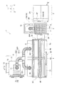
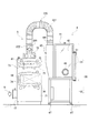
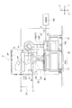
図1は、本発明の封じ込めシステムの実施形態を示す正面図である。図2は、図1に示す封じ込めシステム1の平面図である。図3は、図1に示す封じ込めシステム1のエンクロージャ4とHEPAフィルタボックス5を左側から見た側面図である。図4は、図1に示す封じ込めシステム1のエンクロージャ4を右側から見た側面図である。図5は、封じ込めシステム1における排気系統と制御系統の例を示す図である。
FIG. 1 is a front view showing an embodiment of a containment system of the present invention. FIG. 2 is a plan view of the containment system 1 shown in FIG. FIG. 3 is a side view of the
<封じ込めシステム1の概要>
図1と図2に示す封じ込めシステム1は、例えば半乾燥状態や未乾燥状状態の結晶サンプル等の少量のサンプル等の処理対象物Mを封じ込めながら処理を行う。封じ込めシステム1は、この処理対象物Mや、この処理対象物Mに対して所定の処理をする際に発生する粉体やガス等の目に見えないハザード物質を、封じ込めシステム1の外部に漏らさないようにして処理対象物Mを封じ込めながら、複数の処理部間で安全に移動させることができる構造を有する。この封じ込めシステム1は、好ましくは次に説明する複数の装置群から構成されている。
<Outline of containment system 1>
The containment system 1 shown in FIGS. 1 and 2 performs processing while containing a processing object M such as a small sample such as a semi-dried or undried crystal sample. The containment system 1 leaks to the outside of the containment system 1 invisible hazard substances such as the processing object M and powder or gas generated when the processing object M is subjected to a predetermined process. It has a structure that can be safely moved between a plurality of processing units while containing the processing object M in such a way as to prevent the processing target M from being contained. The containment system 1 is preferably composed of a plurality of device groups described below.
図1と図2に示すように、封じ込めシステム1は、好ましくは、真空定温乾燥機2と、昇降装置3と、エンクロージャ4と、HEPAフィルタボックス5を備えている。
As shown in FIGS. 1 and 2, the containment system 1 preferably includes a vacuum
真空定温乾燥機2は、処理対象物Mを真空状態下で封じ込めて、定温加熱して乾燥させるための第1処理部の例である。エンクロージャ4は、例えば処理対象物Mを大気圧下で封じ込めて処理するための第2処理部の例である。
The vacuum
図1と図2に示す例では、昇降装置3は、第1処理部である真空定温乾燥機2と、第2処理部であるエンクロージャ4との間に配置されている。この昇降装置3は、処理対象物Mを封じ込めながら、真空定温乾燥機2内の処理対象物Mをエンクロージャ4内へ移して受け渡すための受け渡し部の一例である。
In the example shown in FIGS. 1 and 2, the
なお、図1と図2に示すX方向は、封じ込めシステム1の左右方向を示し、Y方向は、封じ込めシステム1の前後方向(奥行き方向)を示し、そしてZ方向は、封じ込めシステム1の上下方向(昇降方向)を示している。 1 and 2 indicate the left-right direction of the containment system 1, the Y direction indicates the front-rear direction (depth direction) of the containment system 1, and the Z direction is the up-down direction of the containment system 1. (Elevating direction) is shown.
図1から図4に示すように、真空定温乾燥機2と、昇降装置3と、エンクロージャ4は、それぞれアジャスタ付きの可動用のキャスタ2T、3T、4Tを有している。このため、真空定温乾燥機2と昇降装置3とエンクロージャ4の位置は、アジャスタ付きの可動用のキャスタ2T、3T、4Tを用いてそれぞれ移動することができ、真空定温乾燥機2と昇降装置3とエンクロージャ4の配置位置は変更可能である。
As shown in FIGS. 1 to 4, the vacuum
これにより、キャスタ2T、3T、4Tは、作業内容に応じて、真空定温乾燥機2と昇降装置3とエンクロージャ4の位置関係を、作業内容に応じて容易に変えることができる。そして、アジャスタ付きの可動用のキャスタ2T、3T、4Tのアジャスタを例えば足踏み操作することで、アジャスタは床面に突き当てることできる。従って、真空定温乾燥機2と昇降装置3とエンクロージャ4は、所定の位置で移動しないようにそれぞれ固定できる。
Accordingly, the
<真空定温乾燥機2>
図1と図2に示す真空定温乾燥機2は、例えば角型真空定温乾燥機であり、少なくとも1つの未乾燥あるいは半乾燥された処理対象物Mを、真空状態において、予め定めた定温下で、加熱して乾燥することができる。図1と図2に示すレイアウト例では、真空定温乾燥機2の開閉扉2Bは、昇降装置3の右側の位置において、昇降装置3側に向けて配置されている。
<Vacuum
A vacuum
真空定温乾燥機2は、真空圧状態で、例えば薬品の結晶サンプルのような処理対象物Mを封じ込めて、パネルヒータ2Dにより定温下で加熱する機能を有する。真空定温乾燥機2は、耐熱性を有する金属、例えばステンレス等により作られた箱型の槽(チャンバ)である。
The vacuum
図1に示すように、真空定温乾燥機2は、本体部2Aと、開閉扉2Bと、真空吸引部2Cと、パネルヒータ2Dを有している。本体部2Aと開閉扉2Bは、図1において破線で示すように、箱型の密閉可能な直方体形状の真空加熱処理空間SRを構成している。開閉扉2Bは、本体部2Aに対して例えばヒンジを用いて片開き式で開閉可能に取り付けられている。開閉扉2Bは、閉じることで本体部2Aの前面開口部2Pを密閉状態で閉鎖する。
As shown in FIG. 1, the vacuum
図1に示すパネルヒータ2Dは、真空加熱処理空間SR内の雰囲気を、定温状態で加熱する面状のヒータであり、真空加熱処理空間SRの天井面、側面、底面、そして好ましくは開閉扉2Bの内面側にも配置されている。これにより、パネルヒータ2Dは、真空加熱処理空間SR内の雰囲気内の処理対象物Mを、定温で加熱して乾燥することができる。
The
図1と図2に示すように、真空定温乾燥機2の開閉扉2Bは、昇降装置3に対面するように、真空定温乾燥機2の本体部2Aが昇降装置3側に向けて配置されている。これにより、作業者が、真空定温乾燥機2の開閉扉2Bの取手2Eを持って開けて、本体部2A内から処理対象物Mを取り出して、昇降装置3側に移す動作を、素早くしかも容易に行うことができる。
As shown in FIGS. 1 and 2, the opening /
なお、真空定温乾燥機2は、開閉扉2Bを開閉している時には、槽内である真空加熱処理空間SR内を、排気しており、真空加熱処理空間SR内の粉体等が外部に飛散しないような構造を有する。
The vacuum
<昇降装置3>
図1と図2に示す昇降装置3は、処理対象物Mに付着している粉体やガス等の目に見えないハザード物質を除去するフィルタユニットを備えている。すなわち、昇降装置3は、フィルタユニット搭載型の受け渡し部の一例である。昇降装置3の位置は、可動用のキャスタ2Tを用いて移動して、しかも位置決め可能である。
<Elevating
The lifting / lowering
特に好ましくは、昇降装置3は、処理対象物Mに付着している粉体やガス等の目に見えないハザード物質を除去するために、HEPAフィルタユニット14を搭載している。この昇降装置3は、真空定温乾燥機2とエンクロージャ4の間に配置されている。
Particularly preferably, the
図6は、昇降装置3の構造を示す側面図である。図7は、昇降装置3の昇降台11の構造例を示す図である。図8は、昇降装置3の構造を示す正面図である。図9は、昇降装置3の構造を示す平面図である。
FIG. 6 is a side view showing the structure of the
図1と図2と図6から図9に示す昇降装置3は、耐熱性を有する金属、例えばステンレス等により作られている。図1と図6に示すように、昇降装置3は、基部10と、矩形型の昇降台11と、昇降用のアクチュエータ12と、フィルタユニットである好ましくはHEPAフィルタユニット14を備える。
The
図2と図6に示すように、基部10は、昇降台11を支えると共に、HEPAフィルタユニット14を収容している。この基部10は、Y方向に沿って長くなるように長方形状で、しかも箱型に形成されている。基部10は、昇降台11を支える領域10Aと、昇降台11からY方向に突き出てHEPAフィルタユニット14を収容している領域10Bを有する。
As shown in FIGS. 2 and 6, the
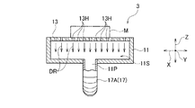
図1と図2に示す昇降台11は、特に耐熱性を有する金属、例えば鋼等により作られている。図7に示すように、昇降台11は、例えば矩形型の中空の部材である。図1と図2と図7に示すように、昇降台11の上面部には、作業面を形成する作業面部13が、着脱可能に配置されている。この作業面部13は、好ましくは耐熱性を有する、例えばステンレス製のパンチングした矩形型の板部材である。
The
図2と図7に示すように、この作業面部13には、好ましくはその全面に渡って、例えば複数の孔部13Hが、形成されている。作業面部13が、必要に応じて昇降台11から取り外せるので、作業面部13の孔部13Hが詰まった場合等における清掃等のメンテナンス作業が容易にできる。
As shown in FIGS. 2 and 7, the
これにより、真空定温乾燥機2において真空加熱された処理対象物Mを、受け渡す際に、この昇降台11の作業面部13の上に載せると、作業面部13は、加熱済みの処理対象物Mが発生している熱を複数の孔部13Hを通じて放散する。しかも、図7に例示するように、作業面部13は、複数の孔部13Hを通じて、処理対象物Mの粉体等のハザード物質を含む空気DRを、昇降台11の空間11S内へ通過させる。
Thus, when the processing object M vacuum-heated in the vacuum
図6と図8に示すように、基部10の領域10Aの上には、固定板部85が水平に固定されている。昇降台11の下部は、支持部材87の上部に固定されている。支持部材87の下部は、可動板部86の上に固定されている。
As shown in FIGS. 6 and 8, a fixed
可動板部86は、固定板部85の上部に平行に配置されており、可動板部86と固定板部85は、図8に示すように左右のリンク部80,80により連結されている。各リンク部80の第1リンク部材81と第2リンク部材82の中間部は、連結部材83で連結している。これにより、可動板部86と昇降台11は、固定板部85に対して、Z方向に沿って移動可能である。
The
図2と図8に示すように、昇降用のアクチュエータ12の本体の端部は、基部10の領域10A側の固定板部85に例えばピンを用いて取り付けられている。図8に示すように、この昇降用のアクチュエータ12の伸縮ロッド12Rは、昇降台11の下部の可動板部86に例えばピンを用いて取り付けられている。昇降用のアクチュエータ12としては、例えば油圧シリンダや空気圧シリンダあるいは電動シリンダを採用できる。あるいは、昇降用のアクチュエータ12としては、モータとこのモータの出力軸に連結された送りネジとから成るリニアアクチュエータであっても良い。
As shown in FIGS. 2 and 8, the end of the main body of the lifting
図8に示す昇降用のアクチュエータ12は、制御部100の指令により、基部10側を基準として、図6に示す昇降台11の作業面部13を、Z方向に沿って所定ストロークSTだけ、上限位置ULと下限位置LLの間で、昇降台11の作業面部13を昇降する。これにより、ことにより、昇降台11の作業面部13は、ストロークST間において、複数の高さ位置において、位置決め可能である。
The elevator actuator 12 shown in FIG. 8 is moved to the upper limit position by a predetermined stroke ST along the Z direction on the
好ましくは、図1と図6に示すこの上限位置ULのZ方向の高さ位置は、真空定温乾燥機2の真空加熱処理空間SRの領域の最も上段の棚板の位置に対応している。また、下限位置LLのZ方向の高さ位置は、次に説明するエンクロージャ4の入れ込み用の開口部20の位置に合わせて、設定されている。例えば、昇降台11は、真空定温乾燥機2の真空加熱処理空間SR内に配置された複数段の棚板の位置に合わせて、上限位置ULと下限位置LLの間で、複数の高さ位置において、それぞれ位置決め可能である。
Preferably, the height position in the Z direction of the upper limit position UL shown in FIGS. 1 and 6 corresponds to the position of the uppermost shelf in the region of the vacuum heat treatment space SR of the vacuum
これにより、作業者は、図1に示す真空定温乾燥機2の開閉扉2Bを開けて、真空加熱処理空間SR内の棚板から処理対象物Mを取り出して、昇降台11の上に素早く載せて、その後この処理対象物Mを、昇降台11上から、エンクロージャ4の開口部20を通じて、エンクロージャ4内の作業空間G内に素早く移して受け渡すことができる。このため、この処理対象物Mの受け渡し作業は、昇降装置3を用いることで、容易にしかも安全に行うことができる。
Thereby, the operator opens the open /
また、上述したように、昇降台11が真空定温乾燥機2の真空加熱処理空間SR内に配置された複数段の棚板の位置に合わせて、上限位置ULと下限位置LLの間で、複数の高さ位置において、それぞれ位置決め可能である。このため、例えば未乾燥あるいは半乾燥された処理対象物Mを、真空定温乾燥機2の真空加熱処理空間SR内に入れて乾燥処理しようとする場合に、昇降台11の上に載せたこの処理対象物Mは、真空定温乾燥機2の真空加熱処理空間SR内に配置された各棚板の上に、容易に入れて載せることができる。
Further, as described above, a plurality of
図6と図8に示すように、HEPAフィルタユニット14の配置位置は、基部10において、昇降台11の配置位置とは異なる位置、すなわちY方向にずれた位置に配置されている。すなわち、HEPAフィルタユニット14は、基部10の領域10A内ではなく、基部10の領域10B内に配置されている。
As shown in FIGS. 6 and 8, the arrangement position of the
このHEPAフィルタユニット14の構造例は、図6と図9に示している。図6と図9に示すように、フィルタユニット14は、フィルタ15と、送風ファン16とから成るHEPA内蔵のファンフィルタユニットであり、室内開放型消音機付きの装置である。フィルタ15は、必要に応じて交換可能である。
An example of the structure of the
このフィルタ15としては、排気フィルタとして例えば空気清浄が求められる分野で使用される高性能フィルタであるHEPAフィルタを使用することが好ましい。しかし、フィルタ15としては、HEPAフィルタの他には、活性炭等の吸着材を用いた吸着材フィルタを用いることができるが、特に限定されない。
As the
図6と図9に示すように、昇降台11の位置とフィルタユニット14の位置は、Y方向に関してずらしてある。しかも、昇降台11は、Z方向に昇降する。そこで、位置の異なる昇降台11とフィルタユニット14とを接続チューブにより接続するために、昇降台11とフィルタユニット14は、伸縮自在の接続管としてのフレキシブルチューブ17により、接続されている。
As shown in FIGS. 6 and 9, the position of the
図7に示すように、フレキシブルチューブ17の一端部17Aは、昇降台11の接続口11Pに対して、着脱可能に取り付けられている。この接続口11Pは、昇降台11の空間11Sに繋がっている。図6と図9に示すように、フレキシブルチューブ17の他端部17Bは、フィルタユニット14の接続口14Pに対して着脱可能に取り付けられている。この接続口14Pは、フィルタユニット14の送風ファン16の上部に位置されている。
As shown in FIG. 7, one
このように、昇降台11とフィルタユニット14は、伸縮自在の接続管としてのフレキシブルチューブ17により接続されていることにより、図1に示すように昇降台11が昇降動作しても、フレキシブルチューブ17は、昇降台11とフィルタユニット14を昇降台11の昇降動作に追従しながら弾性変形することにより、確実に接続状態を維持できる。
As described above, the
図8と図9に例示するように、フィルタユニット14では、送風ファン16はフィルタ15の上流側に配置されている。フィルタ15の下流側には、空気排出部としての下方排気部19が配置されている。下方排気部19は下方排気スリット部ともいう。
As illustrated in FIGS. 8 and 9, in the
フィルタユニット14の送風ファン16が駆動すると、図7に例示するように、処理対象物Mからの粉体等のハザード物質を含む空気DRは、作業面部13の孔部13Hを通って昇降台11の空間11Sを経て、図6に示すフレキシブルチューブ17を通ることで、フィルタユニット14側へ送るようになっている。
When the
これにより、図8において、粉体等のハザード物質は、このフィルタユニット14のフィルタ15により捕獲されて、空気Nはクリーンになる。そして、クリーンになった空気Nは、下方排気部17を通じて、スリットである排気開口部201から外部に放出することができる。
Thereby, in FIG. 8, hazard substances, such as powder, are captured by the
なお、図5と図6に示す使用後のHEPAフィルタのようなフィルタ15は、例えば収容用のバッグに入れてから、さらに好ましくは回収用バッグ内には、収容用のバッグごとフィルタ15を入れて包んだままの状態で、フィルタ15を取り外すことができる。これにより、処理対象物Mを、真空定温乾燥機2内からエンクロージャ4内に移動する際に、使用後のフィルタ15から粉体等のハザード物質が、飛散するのを防止できる。
The
ところで、真空定温乾燥機2は、開閉扉2Bを開閉している時には、槽内である真空加熱処理空間SR内を、上述した昇降装置3のフィルタユニット14の送風ファン16を回転せることで、排気することができる。これにより、真空定温乾燥機2の真空加熱処理空間SR内の粉体等が、真空定温乾燥機2の外部に飛散しない。
By the way, the vacuum
<エンクロージャ4>
図1と図2に示すエンクロージャ4は、昇降装置3の左側に配置されている。
<
The
このエンクロージャ4は、好ましくは、すでに説明したように真空加熱処理済みの処理対象物Mと、その処理対象物Mを処理するための対象の機器を作業空間Gに収容して、この機器を用いて、所定の処理作業を行う。この所定の処理作業としては、例えば結晶サンプルのような処理対象物Mを天秤で秤量して、処理対象物Mを小分けする作業である。
As described above, the
このエンクロージャ4は、その庫内の作業空間Gにおいて、作業者により機器Mを用いて、求められる作業を行う際に、好ましくは、空気を低風量ドラフトで通過させる低風量ドラフトチャンバである。この作業としては、上述したように、例えば結晶サンプルのような乾燥済みの処理対象物Mの分量を、天秤を用いて秤量して小分けしてする処理であるが、特に限定されない。
The
このエンクロージャ4は、近年省エネルギーの観点から、従来の風量より少ない排気風量で稼働できるものが求められている。エンクロージャ4としては、好ましくは例えば排気風量が常に一定(CAV:定風量制御)である定風量型のものが採用できる。しかし、エンクロージャ4は、これに限らず、更なる省エネルギー化の観点から、この定風量型のものに対して、VAV(可変風量制御)方式を組み合わせる可変風量型の物であっても良い。
In recent years, the
エンクロージャ4は、作業や実験における被処理物を内部の作業空間において処理する際に、作業者が被処理物や有害物質の影響を受けないように、内部の作業空間Gの雰囲気を外部から隔離する構造を有している。エンクロージャ4は、作業者を保護することを目的とした局所排気装置であり、危険物質や有害物質の封じ込め機能と、排気機能を有した囲われた作業空間Gを持っている。
The
図1に示すエンクロージャ4は、例えばナノエンクロージャともいい、本体30を有する。この本体30は、例えば正面側から見ると横長の長方形になっている。本体30は、ケース部31と、架台部32を有する。ケース部31の内部の作業空間Gは、本体30の外部に対して閉じたクローズドチャンバ構造を有する。ケース部31は、架台部32と一体化された構造になっており、ケース部31は、架台部32の上に固定されている。
The
図1と図2に示すように、ケース部31は、前面部40と、上面部41と、背面部42と、左右の側面部43,44を有している。作業空間Gは、横長のほぼ直方体形状を有する空間である。ケース部11の前面には、横長の長方形状の前面開口45を有している。この前面開口45は、作業者が例えば対象の機器Mを作業空間G内に搬入したり、搬出するのに用いる。
As shown in FIGS. 1 and 2, the
図1と図2に示すように、ケース部31の前面開口45は、左側の第1前面扉51と、中央の第3前面扉52と、右側の第3前面扉53により、閉されている。第1前面扉51と第3前面扉52と第3前面扉53は、左右方向(X方向)にそれぞれ手動でスライド操作することにより、前面開口45は、開閉可能になっている。
As shown in FIGS. 1 and 2, the
第1前面扉51と第3前面扉52と第3前面扉53は、それぞれ透明な強化ガラスを有するスライドサッシ扉になっているので、作業者は、第1前面扉51と第3前面扉52と第3前面扉53を通して、作業空間G内の機器、例えば天秤等を直接観察することができる。
Since the 1st
図3と図4に示す左右の側面部43,44は、好ましくは作業空間G内が見えるようにするために強化ガラスの透明板である。左側の側面部43には、グローブポート46が設けられている。このグローブポート46は、作業者の手を挿入して作業空間G内で作業を行うための挿肢口である。右側の側面部44には、上述した処理対象物Mを入れ込むための開口部20が設けられている。この処理対象物Mを入れ込むための開口部20は、開閉蓋21により手動で閉じることができる。
The left and right side surfaces 43 and 44 shown in FIGS. 3 and 4 are preferably tempered glass transparent plates so that the inside of the work space G can be seen. A
本体30は、図5に示すように、複数の排気口4Hを備えている。排気口4Hは、本体30の上部であってしかも後側の位置において、上方に向けて突出して設けられている。次に説明するHEPAフィルタボックス5の駆動ファン70が動作することで、作業空間G内の空気や粉体等を複数の排気口4Hを通じて作業空間G内から外部に排出できる。
As shown in FIG. 5, the
<HEPAフィルタボックス5>
図2と図3に示すHEPAフィルタボックス5は、本体71を有するフィルタ装置である。HEPAフィルタボックス5は、エンクロージャ4内の作業空間G内の粉体等のハザード物質等を含む空気を集めて、粉体等のハザード物質を集塵する機能を有する。
<
The
図3に示すように、HEPAフィルタボックス5の本体71内には、プレフィルタ61と、HEPAフィルタ(PTFE)62が着脱可能に装着されている。
As shown in FIG. 3, a
図3に示すように、HEPAフィルタボックス5は、駆動ファン70と、本体71と、排気部72を有する。本体71は、金属製の箱体であり、本体71の前面は、蓋部材73と、蓋部材74を有する。蓋部材73,74は、それぞれ本体71の開口部75,76を閉鎖するために、例えば複数本のネジを用いて本体71に対して固定されている。
As shown in FIG. 3, the
これにより、作業者は、これらの蓋部材73を取り外すことで、開口部75を通じて、新しいプレフィルタ61を装着したり、使用済みのプレフィルタ61を取り外すことができる。同様にして、作業者は、これらの蓋部材74を取り外すことで、開口部76を通じて、新しいHEPAフィルタ62を装着したり、使用済みのHEPAフィルタ62を取り外すことができる。
Thus, the operator can attach a
プレフィルタ61は、例えば活性炭等の吸着材フィルタであり、HEPAフィルタ62は、空気清浄が求められる分野で使用される高性能フィルタである。
The pre-filter 61 is an adsorbent filter such as activated carbon, and the
図3に示す駆動ファン70が駆動されることにより、エンクロージャ4のケース部31の作業空間G内の粉体等のハザード物質等を含む空気BRが本体71内に取り込まれ、プレフィルタ61が予め大きな物質を空気BRから取り除き、その後HEPAフィルタ62がより小さな物質を空気BRから取り除くようになっている。
3 is driven, air BR including a hazard substance such as powder in the work space G of the
なお、図3と図5に示す使用後のプレフィルタ61とHEPAフィルタ62は、それぞれ例えば収容用のバッグに入れてから、さらに好ましくは回収用バッグ内には、収容用のバッグごとプレフィルタ61とHEPAフィルタ62を別々に入れて、包んだままの状態でプレフィルタ61とHEPAフィルタ62を取り外すことができる。これにより、プレフィルタ61とHEPAフィルタ62に付着している粉体等のハザード物質が、外部に飛散するのを防止できる。
The
次に、図5を参照して、図1と図2に示す封じ込めシステム1における排気系統と、制御系統の好ましい例を説明する。 Next, a preferable example of the exhaust system and the control system in the containment system 1 shown in FIGS. 1 and 2 will be described with reference to FIG.
<封じ込めシステム1における排気系統200>
まず、図5を参照して、封じ込めシステム1における排気系統の好ましい例を説明する。
<
First, with reference to FIG. 5, the preferable example of the exhaust system in the containment system 1 is demonstrated.
封じ込めシステム1における排気系統200は、昇降装置3の排気開口部201と、エンクロージャ4とHEPAフィルタボックス5とを接続する排気管路220を備える。
The
すでに説明したように、排気開口部201は、図6と図8に示す昇降装置3の本体10の領域10B内のフィルタユニット14の下流側に接続されている。処理対象物Mがこの昇降台11の作業面部13上に載っていると、この処理対象物Mの粉体等のハザード物質は、排気ファン16の回転により、昇降装置3内のフィルタユニット14のフィルタ15により捕獲され、図8に示すように、清浄化された空気Nが排気開口部201から、本体10の外部に排出される。
As already described, the
一方、図5に示す排気管路220としては、図2と図3に例示するように、例えば伸縮可能なフレキシブルチューブを用いることができる。この排気管路220の一端部221は、エンクロージャ4の上部に配置された複数の排気口4Hに着脱可能に接続されている。排気管路220の他端部222は、HEPAフィルタボックス5の駆動ファン70側の接続口に着脱可能に接続されている。
On the other hand, as the
<封じ込めシステム1における制御系統300>
図5に示す制御部100は、真空定温乾燥機2における真空吸引部2Cの吸引動作と、パネルヒータ2Dの通電動作を制御する。制御部100は、昇降装置3の排気ファン16の回転動作と、昇降用のアクチュエータ12の伸縮動作の制御をする。制御部100は、HEPAフィルタボックス5の駆動ファン70の回転動作の制御をする。
<
The
<封じ込めシステム1の使用例>
次に、上述した構成を有する封じ込めシステム1の使用例を、図10を参照して説明する。
<Usage example of containment system 1>
Next, an example of use of the containment system 1 having the above-described configuration will be described with reference to FIG.
図10は、封じ込めシステム1の使用例を示すフロー図である。 FIG. 10 is a flowchart showing an example of use of the containment system 1.
図10のステップST1では、図1に示す真空定温乾燥機2の本体部2Aにおいて、開閉扉2Bを開いて、処理対象物Mは、箱型の密閉可能な直方体形状の真空加熱処理空間SR内に配置される。
In step ST1 of FIG. 10, in the
この際には、昇降台11が真空定温乾燥機2の真空加熱処理空間SR内に配置された複数段の棚板の位置に合わせて、図1に示す上限位置ULと下限位置LLの間で、複数の高さ位置において、それぞれ位置決め可能になっている。
At this time, the
これにより、まずは、昇降台11の上に載せた未乾燥あるいは半乾燥の処理対象物Mを、真空定温乾燥機2の真空加熱処理空間SR内に配置された各棚板の上に引き入れて載せる作業が、容易にしかも確実に行える。このようにして、処理対象物Mは、真空加熱処理空間SR内の複数段の棚板の内のいずれかの高さ位置の棚板の上に置かれる。
Thereby, first, the undried or semi-dried processing object M placed on the
図1に示す開閉扉2Bを閉じて真空加熱処理空間SRを密閉した後、パネルヒータ2Dが、制御部100の指令により、真空加熱処理空間SR内の雰囲気を、定温状態で加熱する。これにより、未乾燥あるいは半乾燥の処理対象物Mは、所定の乾燥温度で安定して定温乾燥することができる。
After closing the open /
処理対象物Mの定温乾燥が終了すると、図1に示す真空定温乾燥機2の開閉扉2Bを開ける。真空定温乾燥機2の開閉扉2Bは、昇降装置3に対面するように、真空定温乾燥機2の本体部2Aが向けて配置されている。これにより、作業者が、真空定温乾燥機2の開閉扉2Bの取手2Eを持って開けて、本体部2A内から乾燥された処理対象物Mを取り出して、昇降装置3側に受け渡す動作を、容易にしかも確実に行うことができる。
When the constant temperature drying of the processing object M is completed, the open /
次に、図10のステップST2では、図8に示す制御部100の指令により、図1と図6において、昇降用のアクチュエータ12は、昇降台11を、Z方向に沿って所定ストロークSTの間で昇降して、上限位置ULと下限位置LLの間で、複数段階で位置決め可能である。例えば、昇降台11は、真空定温乾燥機2の真空加熱処理空間SR内において、乾燥後の処理対象物Mが置かれた棚板の位置に合わせて、上限位置ULと下限位置LLの間で、Z方向に関して高さ方向の位置決めが行われる。
Next, in step ST2 of FIG. 10, in accordance with a command from the
これにより、作業者は、図1に示す真空定温乾燥機2の開閉扉2Bを開けて、真空加熱処理空間SR内から乾燥された処理対象物Mを取り出して、容易にしかも安全に、素早く昇降台11側に受け渡して昇降台11の作業面部13の上に載せることができる。
Thereby, the operator opens the open /
図10のステップST3では、上述したように昇降装置3が、処理対象物Mを、真空定温乾燥機2からエンクロージャ4内の作業空間G内に受け渡す際には、昇降台11に載せた状態の乾燥された処理対象物Mに付着している粉体等のハザード物質は、次のようにして安全に処理される。
In step ST3 of FIG. 10, when the lifting / lowering
具体的には、図6に示す制御部100の指令により、フィルタユニット14の送風用のファン16が駆動すると、図7に示す処理対象物Mの粉体等のハザード物質を含む空気DRは、搭載台11の空間11Sからフレキシブルチューブ17を通じて、図6に示すフィルタユニット14側へ吸引してフィルタユニット14に通す。
Specifically, when the
このため、粉体等のハザード物質を含む空気は、図8に示すこのフィルタユニット14のフィルタ15により捕獲してクリーンな空気Nとなる。そして、クリーンになった空気Nが、下方排気案内部17内に導かれた後に、排気開口部201から外部に放出する。
For this reason, air containing hazard substances such as powder is captured by the
このようにして、昇降装置3が、処理対象物Mを、真空定温乾燥機2からエンクロージャ4内の作業空間G内に受け渡す際に、粉体等のハザード物質は、処理対象物Mから吸引して回収できるので、粉体等のハザード物質が、昇降装置3の周囲に飛散するのを防止することができる。
In this way, when the
図10のステップST4では、図5の制御部100の指令により、図1に示す昇降用のアクチュエータ12は、昇降台11を、Z方向に沿って下限位置LLに下げると、昇降台11の位置は、エンクロージャ4の開口部20の位置に合わせることができる。
In step ST4 of FIG. 10, when the
これにより、乾燥された処理対象物Mは、昇降台11上から、エンクロージャ4の開口部20を通じて、エンクロージャ4内の作業空間G内に移す受け渡し作業を、素早く行うことができ、この受け渡し作業を、容易にしかも安全に行うことができる。
As a result, the dried processing object M can be quickly transferred from the
図10のステップST5では、処理対象物Mには、図1に示すエンクロージャ4内の作業空間G内において、所定の処理が行われる。この所定の処理とは、例えば乾燥された結晶サンプル等の処理対象物Mを天秤で秤量して、所定量に小分けする作業等であるが、特に限定されない。
In step ST5 of FIG. 10, a predetermined process is performed on the processing object M in the work space G in the
図10のステップST6では、エンクロージャ4において処理対象物Mの処理中には、図5に示す制御部100の指令により、図3に示す駆動ファン70が駆動されることにより、図3に示すエンクロージャ4のケース部31内の粉体等のハザード物質等を含む空気BRが、排気系統200の排気管路220を介して、本体71内に取り込まれる。
In step ST6 of FIG. 10, during processing of the processing object M in the
これにより、図3のプレフィルタ61が、粉体等のハザード物質等を含む空気BRから予め大きな物質を取り除き、その後HEPAフィルタ62が、より小さな物質を空気BRから取り除いて、排気部72から清浄化された空気Nとして排出される。エンクロージャ4内の作業空間G内から粉体等が外部に飛散することがなくなり、封じ込めシステム1が配置された周囲の環境に悪影響を与えない。
As a result, the
その後、図10のステップST7では、図1に示すエンクロージャ4内の作業空間G内から処理済みの処理対象物Mが、取り出される。
Thereafter, in step ST7 of FIG. 10, the processed processing object M is taken out from the work space G in the
上述したように、図5と図3に示す使用後のフィルタ15,61,62を回収して新しいフィルタに交換する場合には、使用後のフィルタ15,61,62は、好ましくは、それぞれ収容用のバッグに入れてから、さらに好ましくは回収用バッグ内には、収容用のバッグごとフィルタ15,61,62を入れた状態で、フィルタ15,61,62を取り外すことができる。
As described above, when the used filters 15, 61, 62 shown in FIGS. 5 and 3 are collected and replaced with new filters, the used filters 15, 61, 62 are preferably accommodated respectively. More preferably, the
これにより、使用後のフィルタ15,61,62を回収して交換する際に、使用後のフィルタ15,61,62から粉体等のハザード物質が、周囲に飛散するのを防止できる。このフィルタ15,61,62を取り除く方式は、バッグアウト方式(Bagout方式)と呼ぶことができる。
Thereby, when the used filters 15, 61, 62 are collected and replaced, it is possible to prevent hazard substances such as powder from scattering from the used filters 15, 61, 62 to the surroundings. A method of removing the
以上説明したように、本発明の実施形態の封じ込めシステム1は、処理対象物Mを封じ込めて、複数の処理部において順次所定の処理を施すためのシステムである。 As described above, the containment system 1 according to the embodiment of the present invention is a system for containing the processing object M and sequentially performing a predetermined process in a plurality of processing units.
この封じ込めシステム1は、処理対象物Mを封じ込めて加熱対象物Mを処理する第1処理部としての例えば真空定温乾燥機2と、第1処理部で処理された処理対象物Mを封じ込めて処理をする第2処理部としての例えばエンクロージャ4と、第1処理部と第2処理部の間に配置されて、第1処理部内の処理対象物Mを第2処理部内へ移す際に受け渡すための受け渡し部としての昇降装置2を備える。そして、この受け渡し部としての昇降装置2は、処理対象物Mに付着している物質を除去するフィルタユニット14を備える。
The containment system 1 contains, for example, a vacuum
これにより、封じ込めシステム1では、受け渡し部としての昇降装置2は、第1処理部と第2処理部の間に配置されて、第1処理部内の処理対象物Mを第2処理部内へ移す際に受け渡す際に、フィルタユニット14が、処理対象物Mに付着している物質を除去する。
Thereby, in the containment system 1, when the raising / lowering
このため、封じ込めシステム1は、従来必要であった密閉容器を用いずに、粉体やガス等の目に見えないハザード物質のような処理対象物Mに付着している物質が外部に漏れないように結晶サンプル等の処理対象物Mを封じ込めながら、処理対象物Mを複数の処理部間で安全にしかも容易に移動することができる。 For this reason, the containment system 1 does not leak a substance adhering to the processing object M such as an invisible hazard substance such as powder or gas without using a sealed container which has been necessary in the past. As described above, the processing object M can be safely and easily moved between the plurality of processing units while containing the processing object M such as a crystal sample.
従来では、密閉容器を用意しておき、粉体やガス等のハザード物質を密閉容器内に収容して封じ込める必要があった。このため、従来では、密閉容器自体の外装の汚染や密閉容器のハンドリングが煩雑になり、処理作業工程が複雑になっていた。 Conventionally, it has been necessary to prepare a sealed container, and to store a hazard substance such as powder and gas in the sealed container and contain it. For this reason, conventionally, the contamination of the exterior of the sealed container itself and the handling of the sealed container have become complicated, and the processing operation process has been complicated.
しかし、本発明の実施形態の封じ込めシステム1では、このような密閉容器が不要となり、封じ込めシステム1を用いることで、粉体やガス等の目に見えないハザード物質の移動に関わる安全度(安心度)を上げることができる。 However, in the containment system 1 according to the embodiment of the present invention, such a sealed container is not necessary, and the use of the containment system 1 makes it possible to ensure the safety level related to the movement of invisible hazard substances such as powder and gas (reliable). Degree).
また、このフィルタユニット14は、フィルタ15と、処理対象物Mに付着している物質を、好ましくはHEPAフィルタのようなフィルタ15に吸着させるためのファン16を有するファンフィルタユニットである。
The
これにより、封じ込めシステム1では、ファンの動作により、処理対象物Mに付着している物質は、好ましくはHEPAフィルタのようなフィルタ15に吸着させて回収できる。従って、処理対象物Mから生じる物質が受け渡し部としての昇降装置2から外部に漏れるのを防げる。
Thereby, in the containment system 1, the substance adhering to the process target object M can be preferably made to adsorb | suck and collect | recover by the
封じ込めシステム1では、受け渡し部としての昇降装置2は、処理対象物Mを載せる昇降台11と、昇降台11を所定の範囲で昇降可能であり、第1処理部内の処理対象物Mを第2処理部部内へ受け渡す際に昇降台11の高さの調整を行うアクチュエータ12と、処理対象物Mに付着している物質を吸着して除去する際に、物質を除去した後の空気を下方へ導いて排出する空気排出部としての下方排気部19と、を備える。
In the containment system 1, the
これにより、封じ込めシステム1では、アクチュエータ12は、昇降台の高さ位置を第1処理部と第2処理部に合わせて調整できるので、処理対象物Mは第1処理部から第2処理部へ、容易にしかも安全に受け渡すことができる。しかも、空気排出部としての下方排気部19は、処理対象物Mから生じる物質を除去した後の空気を下方に導いて排出するので、処理対象物Mから生じる物質が受け渡し部としての昇降装置2から外部に漏れるのを防げる。
Thereby, in the containment system 1, since the
また、封じ込めシステム1では、アクチュエータ12は、昇降台11の高さを、第1処理部例えば真空定温乾燥機2内に配置されて処理対象物Mを載せるための棚板の位置と、第2処理部としてのエンクロージャ4内へ処理対象物を入れるための入れ込み用の開口部20の位置にそれぞれ対応して調整可能である。
In the containment system 1, the
これにより、昇降台の高さ位置は、第1処理部内に配置されて処理対象物を載せるための棚板の位置と、第2処理部内へ処理対象物を入れるための入れ込み用の開口部の位置にそれぞれ合わせて調整できるので、処理対象物は、受け渡し部を介して、第1処理部内の棚板の上から第2処理部の入れ込み用の開口部を通じて、第2処理部内にスムーズにしかも安全に受け渡すことができる。 Thereby, the height position of the lifting platform is set in the position of the shelf for placing the processing object placed in the first processing unit and the opening for inserting the processing object into the second processing unit. Since it can be adjusted according to the position, the object to be processed can be smoothly fed into the second processing section from the top of the shelf in the first processing section through the opening for insertion of the second processing section through the transfer section. It can be delivered safely.
封じ込めシステム1では、昇降台11には、処理対象物Mを載せた状態で、処理対象物Mに付着している物質と空気を通すための複数の孔部13Hを有する板部材13を備える。
In the containment system 1, the
これにより、封じ込めシステム1では、処理対象物Mは、第1処理部から昇降台11の板部材13の上に載せると、粉体やガス等の目に見えない物質は、板部材の孔部13Hを通じて回収することができる。従って、粉体やガス等の目に見えない物質を外部に漏れないように処理対象物Mを封じ込めながら、処理対象物Mを複数の処理部間で安全にしかも容易に移動することができる。
Thereby, in the containment system 1, when the processing object M is placed on the
封じ込めシステム1では、第1処理部は、処理対象物Mを封じ込めて真空状態で加熱する真空乾燥機であり、第2処理部は、処理対象物Mを封じ込めるエンクロージャである。 In the containment system 1, the first processing unit is a vacuum dryer that contains the processing object M and heats it in a vacuum state, and the second processing unit is an enclosure that contains the processing object M.
これにより、封じ込めシステム1では、処理対象物Mは、第1処理部である真空乾燥機により真空乾燥した後に、処理対象物Mから生じる物質は、受け渡し部において回収しながら、第2処理部であるエンクロージャ側に受け渡すことができる。このため、粉体やガス等の目に見えない物質を外部に漏れないように処理対象物Mを封じ込めながら、処理対象物Mを複数の処理部間で安全にしかも容易に移動することができる。 Thereby, in the containment system 1, after the processing object M is vacuum-dried by the vacuum dryer which is a 1st process part, the substance which arises from the process object M is collect | recovered in a delivery part, in a 2nd process part. Can be passed to a certain enclosure side. For this reason, it is possible to safely and easily move the processing object M between a plurality of processing units while enclosing the processing object M so that invisible substances such as powder and gas do not leak outside. .
封じ込めシステム1では、第1処理部は、処理対象物Mを封じ込めて加熱する真空乾燥機や恒温器、安定性試験機であり、第2処理部は、処理対象物を封じ込めるエンクロージャである。これにより、第1処理部としては、真空乾燥機や恒温器、安定性試験機を採用することで、各種の試験や実験等が行える。 In the containment system 1, the first processing unit is a vacuum dryer, a thermostat, or a stability tester that contains and heats the processing object M, and the second processing unit is an enclosure that stores the processing object. Thereby, as a 1st process part, various tests, experiments, etc. can be performed by employ | adopting a vacuum dryer, a thermostat, and a stability tester.
封じ込めシステム1では、フィルタユニットは、バッグ内に入れて封じたバッグアウト方式により取り外される。これにより、取り換えの際に、フィルタユニットから粉体等のハザード物質が、周囲に飛散するのを防止できる。 In the containment system 1, the filter unit is removed by a bag-out method in which the filter unit is sealed in a bag. Thereby, it can prevent that hazard substances, such as powder, scatter from the filter unit at the time of replacement.
封じ込めシステム1では、第1処理部としては、加熱をする真空定温乾燥機に限らず、処理対象物の処理内容に応じて、固体を細かくする粉砕手段(粉砕装置)や、粉をその大きさによって級(クラス)に分ける分級手段(分級装置)を用いることができる。この粉砕手段は、何らかの固体を何らかの方法で細かく砕くことができる。分級手段は、粉(固体が極めて細かい粒の集まりとなっている状態)をその大きさによって級(クラス)に分けることができる。分級により粒の大きさを揃えることによって、粉体の性質が変わる。 In the containment system 1, the first processing unit is not limited to a vacuum constant temperature dryer that heats, but according to the processing content of the processing target, the pulverizing means (pulverizing device) for finely dividing the solid or the size of the powder Classifying means (classifying device) for classifying according to class can be used. This pulverizing means can pulverize some solids by any method. The classifying means can classify powder (a state in which solids are a collection of extremely fine particles) into classes (classes) according to the size. By adjusting the size of the grains by classification, the properties of the powder change.
以上、実施形態を挙げて本発明を説明したが、各実施形態は一例であり、特許請求の範囲に記載される発明の範囲は、発明の要旨を逸脱しない範囲内で種々変更できるものである。 The present invention has been described with reference to the embodiments. However, each embodiment is an example, and the scope of the invention described in the claims can be variously modified without departing from the scope of the invention. .
第1処理部の例としては、真空状態下で処理対象物を封じ込める真空定温乾燥機2を用いている。しかし、第1処理部としては、真空定温乾燥機2以外の他の種類の機器として、大気圧下あるいは真空圧下で、処理対象物を封じ込めて加熱する恒温器、定温乾燥機、恒温乾燥機等の各種の機器であっても良い。第1処理部は、処理対象物を封じ込めて加熱する真空乾燥機や恒温器の他に、安定性試験機であっても良い。
As an example of a 1st process part, the vacuum
第2処理部の例として大気圧下で処理対象物を封じ込めるエンクロージャ4を用いている。しかし、第2処理部としては、処理対象物を封じ込めることができるエンクロージャ4以外の各種の機器であっても良い。
As an example of the second processing unit, an
1 封じ込めシステム
2 真空定温乾燥機(第1処理部の例)
3 昇降装置(受け渡し部の例)
4 エンクロージャ(第2処理部の例)
5 HEPAフィルタボックス
10 昇降装置の本体
11 昇降装置の昇降台
12 昇降装置のアクチュエータ
13 昇降装置の作業面部
14 フィルタユニット
15 フィルタ
16 送風ファン
19 下方排出部(空気排出部の例)
20 入れ込み用の開口部
100 制御部
200 排気系統
300 制御系統
1
3 Lifting device (example of delivery section)
4 Enclosure (example of second processing unit)
5
20
Claims (9)
前記処理対象物を封じ込めて前記処理対象物を処理する第1処理部と、
前記第1処理部で処理された前記処理対象物を封じ込めて処理をする第2処理部と、
前記第1処理部と前記第2処理部の間に配置されて、前記第1処理部内の前記処理対象物を前記第2処理部内へ移す際に受け渡すための受け渡し部と、を備え、
前記受け渡し部は、前記処理対象物に付着している物質を除去するフィルタユニットを備えることを特徴とする封じ込めシステム。 A containment system that contains a processing object and performs a predetermined process,
A first processing unit for containing the processing object and processing the processing object;
A second processing unit for containing and processing the processing object processed by the first processing unit;
A delivery unit disposed between the first processing unit and the second processing unit for delivering the processing object in the first processing unit into the second processing unit;
The containment system, wherein the delivery unit includes a filter unit that removes a substance adhering to the object to be treated.
前記処理対象物を載せる昇降台と、
前記昇降台を所定の範囲で昇降可能であり、前記第1処理部内の前記処理対象物を前記第2処理部部内へ受け渡す際に前記昇降台の高さの調整を行うアクチュエータと、
前記処理対象物に付着している物質を吸着して除去する際に、前記物質を除去した後の空気を下方へ導いて排出する空気排出部と、
を備えることを特徴とする請求項1または2に記載の封じ込めシステム。 The delivery unit is
A lifting platform on which the processing object is placed;
An actuator capable of raising and lowering the lifting platform within a predetermined range, and adjusting the height of the lifting platform when delivering the processing object in the first processing unit into the second processing unit;
When adsorbing and removing the substance adhering to the object to be treated, an air discharge unit that guides and discharges air after removing the substance downward;
The containment system according to claim 1, further comprising:
Priority Applications (1)
| Application Number | Priority Date | Filing Date | Title |
|---|---|---|---|
| JP2016012129A JP6588349B2 (en) | 2016-01-26 | 2016-01-26 | Containment system |
Applications Claiming Priority (1)
| Application Number | Priority Date | Filing Date | Title |
|---|---|---|---|
| JP2016012129A JP6588349B2 (en) | 2016-01-26 | 2016-01-26 | Containment system |
Publications (2)
| Publication Number | Publication Date |
|---|---|
| JP2017131978A true JP2017131978A (en) | 2017-08-03 |
| JP6588349B2 JP6588349B2 (en) | 2019-10-09 |
Family
ID=59504091
Family Applications (1)
| Application Number | Title | Priority Date | Filing Date |
|---|---|---|---|
| JP2016012129A Active JP6588349B2 (en) | 2016-01-26 | 2016-01-26 | Containment system |
Country Status (1)
| Country | Link |
|---|---|
| JP (1) | JP6588349B2 (en) |
Cited By (1)
| Publication number | Priority date | Publication date | Assignee | Title |
|---|---|---|---|---|
| KR101889003B1 (en) * | 2018-04-11 | 2018-08-21 | 주식회사 동재산업 | Control system for face velocity of fume hood |
Citations (7)
| Publication number | Priority date | Publication date | Assignee | Title |
|---|---|---|---|---|
| JPS59112585U (en) * | 1983-01-20 | 1984-07-30 | オリオン機械株式会社 | Workbench with dust removal device |
| JPH05155563A (en) * | 1991-12-04 | 1993-06-22 | Daiichi Shisetsu Kogyo Kk | Conveyor equipped with cleaning means |
| JP3002373U (en) * | 1994-03-25 | 1994-09-20 | 株式会社ジョーニシ | Welding work table with dust collector |
| JP2001035657A (en) * | 1999-07-23 | 2001-02-09 | Semiconductor Energy Lab Co Ltd | El display device and its manufacture |
| JP2007311724A (en) * | 2006-05-22 | 2007-11-29 | Sharp Corp | Substrate transfer method, and substrate processing device |
| JP2014022744A (en) * | 2012-07-19 | 2014-02-03 | Samsung Electro-Mechanics Co Ltd | Non-contact multiple transport apparatus, and foreign matter removing method using the same |
| WO2016009577A1 (en) * | 2014-07-18 | 2016-01-21 | キヤノンアネルバ株式会社 | Method for forming nitride semiconductor layer and method for manufacturing semiconductor device |
-
2016
- 2016-01-26 JP JP2016012129A patent/JP6588349B2/en active Active
Patent Citations (7)
| Publication number | Priority date | Publication date | Assignee | Title |
|---|---|---|---|---|
| JPS59112585U (en) * | 1983-01-20 | 1984-07-30 | オリオン機械株式会社 | Workbench with dust removal device |
| JPH05155563A (en) * | 1991-12-04 | 1993-06-22 | Daiichi Shisetsu Kogyo Kk | Conveyor equipped with cleaning means |
| JP3002373U (en) * | 1994-03-25 | 1994-09-20 | 株式会社ジョーニシ | Welding work table with dust collector |
| JP2001035657A (en) * | 1999-07-23 | 2001-02-09 | Semiconductor Energy Lab Co Ltd | El display device and its manufacture |
| JP2007311724A (en) * | 2006-05-22 | 2007-11-29 | Sharp Corp | Substrate transfer method, and substrate processing device |
| JP2014022744A (en) * | 2012-07-19 | 2014-02-03 | Samsung Electro-Mechanics Co Ltd | Non-contact multiple transport apparatus, and foreign matter removing method using the same |
| WO2016009577A1 (en) * | 2014-07-18 | 2016-01-21 | キヤノンアネルバ株式会社 | Method for forming nitride semiconductor layer and method for manufacturing semiconductor device |
Cited By (1)
| Publication number | Priority date | Publication date | Assignee | Title |
|---|---|---|---|---|
| KR101889003B1 (en) * | 2018-04-11 | 2018-08-21 | 주식회사 동재산업 | Control system for face velocity of fume hood |
Also Published As
| Publication number | Publication date |
|---|---|
| JP6588349B2 (en) | 2019-10-09 |
Similar Documents
| Publication | Publication Date | Title |
|---|---|---|
| CN106622404B (en) | Laboratory work cabinet with filter installation mechanism | |
| JP5742851B2 (en) | Shot processing device | |
| JP2003512845A (en) | Work table on both sides | |
| CN105744710A (en) | Dust-removing electrostatic-eliminating equipment | |
| JP2019534144A (en) | Cleaning disinfection and drying system | |
| US20080113599A1 (en) | Safety workbench with blower performance controllable dependent on the position of the front pane | |
| JP5015233B2 (en) | System and method for transferring and moving elements of automatic packaging machines | |
| US3926597A (en) | Cabinet for biohazardous materials | |
| JP7041300B1 (en) | Continuous firing system | |
| JP2001025387A (en) | Clean bench | |
| JP6588349B2 (en) | Containment system | |
| JP6663710B2 (en) | Filter replacement device, filter replacement device control method, and gas turbine equipment | |
| CN104907110B (en) | Convenient-application biological safety cabinet | |
| WO2015114831A1 (en) | Weighing system | |
| JP4238861B2 (en) | Safety cabinet and bioclean bench with built-in centrifuge | |
| GB2474629A (en) | Purging the atmosphere in an area | |
| JP2017039081A (en) | Equipment-confining apparatus | |
| JP6875320B2 (en) | Safety cabinet | |
| GB2286986A (en) | Isolator and method of operating it | |
| JP6546463B2 (en) | Equipment containment device | |
| DE102015007987A1 (en) | Device and method for the internal cleaning of technical devices | |
| JP2020150877A (en) | Sample storage device and sample storage system | |
| DE102014000090A1 (en) | Device and method for the internal cleaning of technical devices | |
| JPH1187204A (en) | Clean room system for semiconductor wafer treatment device | |
| JP7028706B2 (en) | Safety cabinet |
Legal Events
| Date | Code | Title | Description |
|---|---|---|---|
| A621 | Written request for application examination |
Free format text: JAPANESE INTERMEDIATE CODE: A621 Effective date: 20180806 |
|
| A131 | Notification of reasons for refusal |
Free format text: JAPANESE INTERMEDIATE CODE: A131 Effective date: 20190521 |
|
| A977 | Report on retrieval |
Free format text: JAPANESE INTERMEDIATE CODE: A971007 Effective date: 20190522 |
|
| A521 | Request for written amendment filed |
Free format text: JAPANESE INTERMEDIATE CODE: A523 Effective date: 20190718 |
|
| TRDD | Decision of grant or rejection written | ||
| A01 | Written decision to grant a patent or to grant a registration (utility model) |
Free format text: JAPANESE INTERMEDIATE CODE: A01 Effective date: 20190903 |
|
| A61 | First payment of annual fees (during grant procedure) |
Free format text: JAPANESE INTERMEDIATE CODE: A61 Effective date: 20190912 |
|
| R150 | Certificate of patent or registration of utility model |
Ref document number: 6588349 Country of ref document: JP Free format text: JAPANESE INTERMEDIATE CODE: R150 |
|
| R250 | Receipt of annual fees |
Free format text: JAPANESE INTERMEDIATE CODE: R250 |
|
| R250 | Receipt of annual fees |
Free format text: JAPANESE INTERMEDIATE CODE: R250 |