JP2017126634A - Coil component - Google Patents
Coil component Download PDFInfo
- Publication number
- JP2017126634A JP2017126634A JP2016004284A JP2016004284A JP2017126634A JP 2017126634 A JP2017126634 A JP 2017126634A JP 2016004284 A JP2016004284 A JP 2016004284A JP 2016004284 A JP2016004284 A JP 2016004284A JP 2017126634 A JP2017126634 A JP 2017126634A
- Authority
- JP
- Japan
- Prior art keywords
- coil
- terminal electrode
- winding
- wires
- core
- Prior art date
- Legal status (The legal status is an assumption and is not a legal conclusion. Google has not performed a legal analysis and makes no representation as to the accuracy of the status listed.)
- Pending
Links
Images


Classifications
-
- H—ELECTRICITY
- H01—ELECTRIC ELEMENTS
- H01F—MAGNETS; INDUCTANCES; TRANSFORMERS; SELECTION OF MATERIALS FOR THEIR MAGNETIC PROPERTIES
- H01F27/00—Details of transformers or inductances, in general
- H01F27/28—Coils; Windings; Conductive connections
- H01F27/2823—Wires
- H01F27/2828—Construction of conductive connections, of leads
-
- H—ELECTRICITY
- H01—ELECTRIC ELEMENTS
- H01F—MAGNETS; INDUCTANCES; TRANSFORMERS; SELECTION OF MATERIALS FOR THEIR MAGNETIC PROPERTIES
- H01F27/00—Details of transformers or inductances, in general
- H01F27/24—Magnetic cores
- H01F27/26—Fastening parts of the core together; Fastening or mounting the core on casing or support
- H01F27/263—Fastening parts of the core together
-
- H—ELECTRICITY
- H01—ELECTRIC ELEMENTS
- H01F—MAGNETS; INDUCTANCES; TRANSFORMERS; SELECTION OF MATERIALS FOR THEIR MAGNETIC PROPERTIES
- H01F27/00—Details of transformers or inductances, in general
- H01F27/28—Coils; Windings; Conductive connections
- H01F27/2823—Wires
-
- H—ELECTRICITY
- H01—ELECTRIC ELEMENTS
- H01F—MAGNETS; INDUCTANCES; TRANSFORMERS; SELECTION OF MATERIALS FOR THEIR MAGNETIC PROPERTIES
- H01F27/00—Details of transformers or inductances, in general
- H01F27/28—Coils; Windings; Conductive connections
- H01F27/29—Terminals; Tapping arrangements for signal inductances
- H01F27/292—Surface mounted devices
-
- H—ELECTRICITY
- H01—ELECTRIC ELEMENTS
- H01F—MAGNETS; INDUCTANCES; TRANSFORMERS; SELECTION OF MATERIALS FOR THEIR MAGNETIC PROPERTIES
- H01F27/00—Details of transformers or inductances, in general
- H01F27/28—Coils; Windings; Conductive connections
- H01F27/30—Fastening or clamping coils, windings, or parts thereof together; Fastening or mounting coils or windings on core, casing, or other support
- H01F27/306—Fastening or mounting coils or windings on core, casing or other support
-
- H—ELECTRICITY
- H01—ELECTRIC ELEMENTS
- H01F—MAGNETS; INDUCTANCES; TRANSFORMERS; SELECTION OF MATERIALS FOR THEIR MAGNETIC PROPERTIES
- H01F27/00—Details of transformers or inductances, in general
- H01F27/34—Special means for preventing or reducing unwanted electric or magnetic effects, e.g. no-load losses, reactive currents, harmonics, oscillations, leakage fields
-
- H—ELECTRICITY
- H01—ELECTRIC ELEMENTS
- H01F—MAGNETS; INDUCTANCES; TRANSFORMERS; SELECTION OF MATERIALS FOR THEIR MAGNETIC PROPERTIES
- H01F3/00—Cores, Yokes, or armatures
- H01F3/10—Composite arrangements of magnetic circuits
Abstract
Description
本発明はコイル部品に関し、特に、ドラム型コアを用いたコイル部品に関する。 The present invention relates to a coil component, and more particularly to a coil component using a drum core.
近年、スマートフォンなどの情報端末に用いられる電子部品に対しては、小型化及び低背化が強く求められている。このため、パルストランスなどのコイル部品についても、トロイダル型コアではなく、ドラム型コアを用いた表面実装型のコイル部品が数多く使用されている。例えば、特許文献1にはドラム型コアを用いた表面実装型のパルストランスが開示されている。 In recent years, electronic components used in information terminals such as smartphones have been strongly demanded to be downsized and reduced in height. For this reason, not only toroidal cores but also surface mount type coil parts using drum cores are used for coil parts such as pulse transformers. For example, Patent Document 1 discloses a surface mount pulse transformer using a drum core.
特許文献1に記載されたパルストランスは、1次側コイルを構成する2本のワイヤ及び2次側コイルを構成する2本のワイヤを備えており、1次側コイルを構成するワイヤの1本と2次側コイルを構成するワイヤの1本が右回り(時計回り)に巻回され、1次側コイルを構成するワイヤの残りの1本と2次側コイルを構成するワイヤの残りの1本が左回り(反時計回り)に巻回されている。このため、1次側コイルを構成するワイヤと2次側コイルを構成するワイヤは、ドラム型コアの巻芯部において複数回に亘って交差することになる。 The pulse transformer described in Patent Document 1 includes two wires constituting the primary coil and two wires constituting the secondary coil, and one of the wires constituting the primary coil. And one of the wires constituting the secondary coil is wound clockwise (clockwise), the remaining one of the wires constituting the primary coil and the remaining one of the wires constituting the secondary coil. The book is wound counterclockwise (counterclockwise). For this reason, the wire which comprises a primary side coil, and the wire which comprises a secondary side coil will cross | intersect in multiple times in the core part of a drum type core.
パルストランスにおいては、1次側コイルと2次側コイルを確実に絶縁する必要があるが、巻芯部上においてはワイヤが規則的に巻回されているため、1次側コイルと2次側コイルが複数回交差しても、両者間に強い電界が生じることはない。一方、ワイヤの端部は、端子電極に接続するために巻芯部から鍔部へと引き出され、引き出し部において1次側コイルを構成するワイヤと2次側コイルを構成するワイヤが交差することがある。引き出し部において1次側コイルを構成するワイヤと2次側コイルを構成するワイヤが交差すると、交差部分において強い電界がかかることがあり、この部分において絶縁耐圧が不足することがあった。特に、ワイヤが端子電極に熱圧着される場合、圧着時の熱がワイヤの引き出し部に伝導することで絶縁被覆が劣化することがあり、これによって交差部分の絶縁耐圧が低下することがあった。 In the pulse transformer, it is necessary to insulate the primary side coil and the secondary side coil reliably, but since the wire is regularly wound on the winding core portion, the primary side coil and the secondary side coil Even if the coils intersect multiple times, no strong electric field is generated between them. On the other hand, the end portion of the wire is drawn from the core portion to the flange portion in order to connect to the terminal electrode, and the wire constituting the primary coil and the wire constituting the secondary coil intersect at the lead portion. There is. When the wire constituting the primary coil and the wire constituting the secondary coil intersect at the lead-out portion, a strong electric field may be applied at the intersecting portion, and the withstand voltage may be insufficient at this portion. In particular, when the wire is thermocompression bonded to the terminal electrode, the insulation coating may be deteriorated due to conduction of heat at the time of crimping to the lead-out portion of the wire, which may reduce the withstand voltage at the intersection. .
したがって、本発明は、ワイヤの引き出し部における絶縁耐圧が改善されたコイル部品を提供することを目的とする。 Accordingly, an object of the present invention is to provide a coil component having an improved withstand voltage at a wire drawing portion.
本発明によるコイル部品は、巻芯部と、前記巻芯部の軸方向における一端に設けられた第1の鍔部と、前記巻芯部の前記軸方向における他端に設けられた第2の鍔部とを含むドラム型コアと、前記第1の鍔部に設けられた第1及び第2の端子電極と、前記第2の鍔部に設けられた第3及び第4の端子電極と、前記巻芯部に巻回され、一端が前記第1の端子電極に接続され、他端が前記第3の端子電極に接続された第1のコイルと、前記巻芯部に巻回され、一端が前記第2の端子電極に接続され、他端が前記第4の端子電極に接続された第2のコイルと、を備え、前記第1及び第2のコイルは、前記巻芯部において規則的に巻回された巻回部と、前記巻回部と前記第1の鍔部との間に位置する第1の引き出し部と、前記巻回部と前記第2の鍔部との間に位置する第2の引き出し部とを含み、前記第1のコイルと前記第2のコイルは、前記第1の引き出し部において交差し、前記第1のコイルは、少なくとも2本のワイヤによって構成されていることを特徴とする。 The coil component according to the present invention includes a winding core, a first flange provided at one end in the axial direction of the winding core, and a second provided at the other end in the axial direction of the winding core. A drum core including a flange, first and second terminal electrodes provided on the first flange, and third and fourth terminal electrodes provided on the second flange, A first coil wound around the core, one end connected to the first terminal electrode and the other end connected to the third terminal electrode; and one end wound around the core Is connected to the second terminal electrode, and the other end is connected to the fourth terminal electrode, and the first and second coils are regularly arranged in the core portion. A winding portion wound around the first winding portion, a first drawer portion positioned between the winding portion and the first collar portion, the winding portion and the second collar portion. A second lead portion positioned between the first coil and the second coil at the first lead portion, and the first coil is formed by at least two wires. It is configured.
本発明によれば、第1のコイルが少なくとも2本のワイヤによって構成されていることから、第1の引き出し部において第1のコイルと第2のコイルが交差するものの、交差部分における電界強度が緩和される。これにより、引き出し部における絶縁耐圧を向上させることができる。 According to the present invention, since the first coil is composed of at least two wires, the first coil and the second coil intersect at the first lead portion, but the electric field strength at the intersecting portion is Alleviated. Thereby, the withstand voltage in the lead portion can be improved.
この場合、前記第1のコイルと前記第2のコイルは、前記巻回部における巻回方向が互いに逆であっても構わない。また、前記第1のコイルと前記第2のコイルは、前記第2の引き出し部において交差しなくても構わない。 In this case, the winding direction of the first coil and the second coil may be opposite to each other. Further, the first coil and the second coil may not intersect at the second lead portion.
本発明によるコイル部品は、前記巻芯部に巻回された第3及び第4のコイルをさらに備え、前記第3及び第4のコイルは、前記巻芯部において規則的に巻回された巻回部と、前記巻回部と前記第1の鍔部との間に位置する第1の引き出し部と、前記巻回部と前記第2の鍔部との間に位置する第2の引き出し部とを含み、前記第3のコイルと前記第4のコイルは、前記第2の引き出し部において交差し、前記第3のコイルは、少なくとも2本のワイヤによって構成されていることが好ましい。これによれば、第3のコイルが少なくとも2本のワイヤによって構成されていることから、第2の引き出し部において第3のコイルと第4のコイルが交差するものの、交差部分における電界強度が緩和される。 The coil component according to the present invention further includes third and fourth coils wound around the core, and the third and fourth coils are wound regularly around the core. A first drawer portion located between the winding portion, the winding portion and the first collar portion, and a second drawer portion located between the winding portion and the second collar portion. It is preferable that the third coil and the fourth coil intersect at the second lead portion, and the third coil is constituted by at least two wires. According to this, since the third coil is composed of at least two wires, the third coil and the fourth coil intersect at the second lead portion, but the electric field strength at the intersecting portion is reduced. Is done.
この場合、前記第1のコイルと前記第4のコイルは、前記巻回部における巻回方向が互いに同じであり、前記第2のコイルと前記第3のコイルは、前記巻回部における巻回方向が互いに同じであり、前記第1及び第4のコイルと前記第2及び第3のコイルは、前記巻回部における巻回方向が互いに逆であっても構わない。また、前記第3のコイルと前記第4のコイルは、前記第1の引き出し部において交差しなくても構わない。 In this case, the first coil and the fourth coil have the same winding direction in the winding part, and the second coil and the third coil are wound in the winding part. The directions may be the same, and the winding directions of the first and fourth coils and the second and third coils may be opposite to each other. Further, the third coil and the fourth coil may not intersect at the first lead portion.
本発明において、前記第1の引き出し部の前記軸方向における距離は、前記第2の引き出し部の前記軸方向における距離よりも広くても構わない。この場合、前記第1のコイルと前記第2のコイルは、前記第1の引き出し部において前記第1のコイルが前記巻芯部上において前記第2のコイルを覆うように交差し、前記第3のコイルと前記第4のコイルは、前記第2の引き出し部において前記第4のコイルが前記巻芯部上において前記第3のコイルを覆うように交差することが好ましい。これによれば、ワイヤの交差部分における物理的ストレスを緩和することができる。 In the present invention, a distance in the axial direction of the first lead portion may be larger than a distance in the axial direction of the second lead portion. In this case, the first coil and the second coil intersect so that the first coil covers the second coil on the core portion in the first lead portion, and the third coil It is preferable that the fourth coil and the fourth coil intersect so that the fourth coil covers the third coil on the core portion in the second lead portion. According to this, physical stress at the crossing portion of the wires can be relieved.
本発明によるコイル部品は、前記第1の鍔部に設けられた第5の端子電極と、前記第2の鍔部に設けられた第6の端子電極とをさらに備え、前記第3のコイルの一端は、前記第5の端子電極に接続され、前記第3のコイルの他端は、前記第3の端子電極に接続され、前記第4のコイルの一端は、前記第2の端子電極に接続され、前記第4のコイルの他端は、前記第6の端子電極に接続されていることが好ましい。これによれば、6端子型のパルストランスとして用いることができる。 The coil component according to the present invention further includes a fifth terminal electrode provided on the first flange and a sixth terminal electrode provided on the second flange, and the coil component of the third coil is provided. One end is connected to the fifth terminal electrode, the other end of the third coil is connected to the third terminal electrode, and one end of the fourth coil is connected to the second terminal electrode. The other end of the fourth coil is preferably connected to the sixth terminal electrode. According to this, it can be used as a 6-terminal type pulse transformer.
本発明によるコイル部品は、前記第1の鍔部に設けられた第5及び第6の端子電極と、前記第2の鍔部に設けられた第7及び第8の端子電極とをさらに備え、前記第3のコイルの一端は、前記第5の端子電極に接続され、前記第3のコイルの他端は、前記第7の端子電極に接続され、前記第4のコイルの一端は、前記第6の端子電極に接続され、前記第4のコイルの他端は、前記第8の端子電極に接続されているもまた好ましい。これによれば、8端子型のパルストランスとして用いることができる。 The coil component according to the present invention further includes fifth and sixth terminal electrodes provided on the first flange, and seventh and eighth terminal electrodes provided on the second flange, One end of the third coil is connected to the fifth terminal electrode, the other end of the third coil is connected to the seventh terminal electrode, and one end of the fourth coil is connected to the fifth terminal electrode. It is also preferable that the other end of the fourth coil is connected to the eighth terminal electrode. According to this, it can be used as an 8-terminal type pulse transformer.
本発明によれば、ワイヤの引き出し部における絶縁耐圧が改善されたコイル部品を提供することが可能となる。 ADVANTAGE OF THE INVENTION According to this invention, it becomes possible to provide the coil components with which the withstand voltage in the drawer part of the wire was improved.
以下、図面を参照しながら、本発明の好ましい実施形態について詳細に説明する。 Hereinafter, preferred embodiments of the present invention will be described in detail with reference to the drawings.
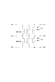
図1は、本発明の第1の実施形態によるコイル部品10Aの外観構造を示す略斜視図である。
FIG. 1 is a schematic perspective view showing an external structure of a
本実施形態によるコイル部品10Aは表面実装型のパルストランスであり、図1に示すように、ドラム型コア20と、ドラム型コア20に接着された板状コア30と、ドラム型コア20の巻芯部21に巻回された6本のワイヤW1〜W6とを備えている。但し、本発明によるコイル部品がパルストランスに限定されるものではなく、バルントランスや昇圧トランスなどの他のトランス部品であっても構わないし、コモンモードチョークコイルなどのフィルタ部品であっても構わない。
The
ドラム型コア20及び板状コア30は、比較的透磁率の高い磁性材料、例えばNi−Zn系フェライトや、Mn−Zn系フェライトの焼結体によって構成されている。なお、Mn−Zn系フェライトなどの透磁率の高い磁性材料は、固有抵抗が低く導電性を有しているのが通常である。
The
ドラム型コア20は、y方向を軸方向とする棒状の巻芯部21と、巻芯部21のy方向における両端に設けられた第1及び第2の鍔部22,23とを備え、これらが一体化された構造を有している。鍔部22は、巻芯部21に接続される内側面22iと、内側面22iの反対側に位置する外側面22oと、巻芯部21の軸方向と平行な底面22bと、底面22bの反対側に位置する上面22tとを有する。同様に、鍔部23は、巻芯部21に接続される内側面23iと、内側面23iの反対側に位置する外側面23oと、巻芯部21の軸方向と平行な底面23bと、底面23bの反対側に位置する上面23tとを有する。内側面22i,23i及び外側面22o,23oはxz平面を構成し、底面22b,23b及び上面22t,23tはxy平面を構成する。
The
コイル部品10Aは、実使用時においてプリント基板上に表面実装される部品であり、鍔部22,23の底面22b,23bを基板に対向させた状態で実装される。鍔部22,23の上面22t,23tには、板状コア30が接着剤により固着されている。このような構造により、ドラム型コア20と板状コア30によって閉磁路が構成される。
The
図1に示すように、鍔部22の底面22b及び外側面22oには3つの端子電極E1〜E3がy方向にこの順に設けられ、鍔部23の底面23b及び外側面23oには3つの端子電極E4〜E6がy方向にこの順に設けられる。端子電極E1〜E6はいずれもL字型の端子金具からなり、接着剤を介して鍔部22又は23に接着されている。L字型の端子金具を用いることにより、ペースト状の金属を焼き付けることによって端子電極E1〜E6を形成する場合と比べて製造コストを低減することが可能となる。
As shown in FIG. 1, three terminal electrodes E1 to E3 are provided in this order in the y direction on the
本実施形態においては、端子電極E1と端子電極E2のx方向における距離よりも、端子電極E2と端子電極E3のx方向における距離の方が長い。同様に、端子電極E4と端子電極E5のx方向における距離よりも、端子電極E5と端子電極E6のx方向における距離の方が長い。これは、鍔部22,23において1次側と2次側の絶縁耐圧を確保するためである。
In the present embodiment, the distance between the terminal electrode E2 and the terminal electrode E3 in the x direction is longer than the distance between the terminal electrode E1 and the terminal electrode E2 in the x direction. Similarly, the distance in the x direction between the terminal electrode E5 and the terminal electrode E6 is longer than the distance in the x direction between the terminal electrode E4 and the terminal electrode E5. This is to ensure the withstand voltage on the primary side and the secondary side in the
巻芯部21には6本のワイヤW1〜W6が巻回されている。ワイヤW1,W2の一端はいずれも端子電極E1に接続され、ワイヤW1,W2の他端はいずれも端子電極E6に接続される。これにより、2本のワイヤW1,W2は、1つのコイルC1を構成する。また、ワイヤW3,W4の一端はいずれも端子電極E2に接続され、ワイヤW3,W4の他端はいずれも端子電極E6に接続される。これにより、2本のワイヤW3,W4は、1つのコイルC2を構成する。さらに、ワイヤW5,W6の一端はいずれも端子電極E3に接続され、ワイヤW5,W6の他端はそれぞれ端子電極E5,E4に接続される。これにより、ワイヤW5,W6は、それぞれ別のコイルC3,C4を構成する。ワイヤW1〜W6の継線は、端子電極E1〜E6のうち底面22b,23bを覆う部分にて行われる。継線の方法については特に限定されないが、熱圧着又はレーザー接合により行うことができる。
Six wires W1 to W6 are wound around the
図2は、コイル部品10Aをz方向から見た平面図である。
FIG. 2 is a plan view of the
図2に示すように、6本のワイヤW1〜W6によって構成されるコイルC1〜C4は、巻芯部21において規則的に巻回された巻回部Caと、巻回部Caと鍔部22との間に位置する第1の引き出し部Cbと、巻回部Caと第2の鍔部23との間に位置する第2の引き出し部Ccとを含む。第1の引き出し部Cbは、ワイヤW1〜W6の一端を端子電極E1〜E3に接続するために巻回部Caから引き出された部分である。同様に、第2の引き出し部Ccは、ワイヤW1〜W6の他端を端子電極E4〜E6に接続するために巻回部Caから引き出された部分である。特に限定されるものではないが、本実施形態においては、第1の引き出し部Cbのy方向における距離は、第2の引き出し部Ccのy方向における距離よりも広い。
As shown in FIG. 2, the coils C <b> 1 to C <b> 4 constituted by the six wires W <b> 1 to W <b> 6 are wound regularly at the winding
ここで、コイルC1を構成するワイヤW1,W2は、端子電極E1から端子電極E6に向かって左回り(反時計回り)に巻回される。コイルC2を構成するワイヤW3,W4は、端子電極E2から端子電極E6に向かって右回り(時計回り)に巻回される。コイルC3を構成するワイヤW5は、端子電極E3から端子電極E5に向かって右回り(時計回り)に巻回される。コイルC4を構成するワイヤW6は、端子電極E3から端子電極E4に向かって左回り(反時計回り)に巻回される。コイルC1は例えば第3のコイルを構成し、コイルC2は例えば第1のコイルを構成し、コイルC3は例えば第4のコイルを構成し、コイルC4は例えば第2のコイルを構成する。 Here, the wires W1 and W2 constituting the coil C1 are wound counterclockwise (counterclockwise) from the terminal electrode E1 toward the terminal electrode E6. The wires W3 and W4 constituting the coil C2 are wound clockwise (clockwise) from the terminal electrode E2 toward the terminal electrode E6. The wire W5 constituting the coil C3 is wound clockwise (clockwise) from the terminal electrode E3 toward the terminal electrode E5. The wire W6 constituting the coil C4 is wound counterclockwise (counterclockwise) from the terminal electrode E3 toward the terminal electrode E4. For example, the coil C1 constitutes a third coil, the coil C2 constitutes a first coil, the coil C3 constitutes a fourth coil, and the coil C4 constitutes a second coil, for example.
かかる構成により、本実施形態によるコイル部品10Aは図3に示す回路を構成する。つまり、端子電極E4,E5を一対の1次側端子とし、端子電極E1,E2を一対の2次側端子とし、端子電極E3を1次側センタータップとし、端子電極E6を2次側センタータップとするパルストランス回路が構成される。これにより、1次側と2次側を直流的に絶縁しつつ、信号成分を通過させることができる。
With this configuration, the
パルストランスにおいては、当然ながら、1次側のコイルC3,C4と2次側のコイルC1,C2との間で絶縁を確保する必要がある。ここで、絶縁耐圧の低下は、1次側のコイルC3,C4と2次側のコイルC1,C2が近接する部分で生じるが、コイルC1〜C4が規則的に巻回された巻回部Caでは、1次側のコイルC3,C4と2次側のコイルC1,C2との間に生じる電界が分散されるため、この部分における絶縁耐圧は問題とならない。 In the pulse transformer, as a matter of course, it is necessary to ensure insulation between the primary side coils C3 and C4 and the secondary side coils C1 and C2. Here, the reduction of the insulation withstand voltage occurs in the portion where the primary side coils C3 and C4 and the secondary side coils C1 and C2 are close to each other, but the winding portion Ca where the coils C1 to C4 are regularly wound. Then, since the electric field generated between the primary side coils C3 and C4 and the secondary side coils C1 and C2 is dispersed, the withstand voltage in this portion is not a problem.
これに対し、第1の引き出し部Cbにおいては、1次側のコイルC4を構成するワイヤW6と2次側のコイルC2を構成するワイヤW3,W4が交差することから、交差部分において電界が集中し、絶縁耐圧が低下するおそれがある。同様に、第2の引き出し部Ccにおいては、1次側のコイルC3を構成するワイヤW5と2次側のコイルC1を構成するワイヤW1,W2が交差することから、交差部分において電界が集中し、絶縁耐圧が低下するおそれがある。 On the other hand, in the first lead portion Cb, the wire W6 constituting the primary side coil C4 and the wires W3 and W4 constituting the secondary side coil C2 intersect with each other, so that the electric field is concentrated at the intersecting portion. In addition, the withstand voltage may be reduced. Similarly, in the second lead portion Cc, the wire W5 constituting the primary side coil C3 and the wires W1 and W2 constituting the secondary side coil C1 intersect, so that the electric field concentrates at the intersection. There is a risk that the withstand voltage will decrease.
しかしながら、本実施形態によるコイル部品10Aにおいては、交差する2つのコイルの一方(C1,C2)が2本のワイヤ(W1とW2又はW3とW4)によって構成されていることから、交差する2つのコイルの両方が1本のワイヤによって構成されている場合と比べ、電界の集中が緩和される。これにより、各コイルC1〜C4をいずれも1本のワイヤによって構成した場合と比べ、高い絶縁耐圧を確保することが可能となる。
However, in the
尚、第2の引き出し部Ccにおいては、1次側のコイルC4を構成するワイヤW6と2次側のコイルC2を構成するワイヤW3,W4は交差しない。同様に、第1の引き出し部Cbにおいては、1次側のコイルC3を構成するワイヤW5と2次側のコイルC1を構成するワイヤW1,W2は交差しない。 In the second lead portion Cc, the wire W6 that constitutes the primary coil C4 and the wires W3 and W4 that constitute the secondary coil C2 do not intersect. Similarly, in the first lead portion Cb, the wire W5 constituting the primary coil C3 and the wires W1 and W2 constituting the secondary coil C1 do not intersect.
ワイヤW1〜W6は、次の方法で巻回することができる。まず、ワイヤW1,W2の他端を端子電極E6に継線し、ワイヤW6の他端を端子電極E4に継線した状態で、ドラム型コア20を回転させることによってこれらワイヤW1,W2,W6を巻芯部21に同方向に巻回する。そして、ワイヤW1,W2の一端を端子電極E1に継線し、ワイヤW6の一端を端子電極E3に継線することにより、コイルC1,C4が完成する。継線は例えば熱圧着により行われ、圧着時に印加される熱がワイヤW1,W2,W6を伝送するため、第1の引き出し部Cbや第2の引き出し部Ccにおいては、ワイヤW1,W2,W6の絶縁被覆に劣化が生じることがある。
The wires W1 to W6 can be wound by the following method. First, the wires W1, W2, W2 are connected to the terminal electrode E6, and the other end of the wire W6 is connected to the terminal electrode E4. Is wound around the
次に、ワイヤW3,W4の一端を端子電極E2に継線し、ワイヤW5の一端を端子電極E3に継線した状態で、再びドラム型コア20を回転させることによってこれらワイヤW3,W4,W5を巻芯部21に同方向に巻回する。そして、ワイヤW3,W4の他端を端子電極E6に継線し、ワイヤW5の他端を端子電極E5に継線することにより、コイルC2,C3が完成する。ワイヤW3,W4,W5の継線も例えば熱圧着により行われ、圧着時に印加される熱がワイヤW3,W4,W5を伝送するため、第1の引き出し部Cbや第2の引き出し部Ccにおいては、ワイヤW3,W4,W5の絶縁被覆に劣化が生じることがある。
Next, one end of the wires W3, W4 is connected to the terminal electrode E2, and one end of the wire W5 is connected to the terminal electrode E3, and the
このため、第1の引き出し部Cbにおいて交差するワイヤW6とワイヤW3,W4は、交差部分において絶縁耐圧が不足するおそれがある。同様に、第2の引き出し部Ccにおいて交差するワイヤW5とワイヤW1,W2は、交差部分において絶縁耐圧が不足するおそれがある。しかしながら、上述の通り、本実施形態においては交差する一方のコイルが2本のワイヤで構成されていることから、電界の集中が緩和され、絶縁耐圧の低下が防止される。 For this reason, the wire W6 and the wires W3 and W4 intersecting at the first lead portion Cb may have insufficient withstand voltage at the intersection. Similarly, the wire W5 and the wires W1, W2 that intersect at the second lead portion Cc may have insufficient withstand voltage at the intersection. However, as described above, in the present embodiment, since one of the intersecting coils is composed of two wires, the concentration of the electric field is alleviated, and a reduction in the withstand voltage is prevented.
また、上述した巻回方法によれば、1回目の巻回工程でワイヤW1,W2,W6が左回り(反時計回り)に巻回され、2回目の巻回工程でワイヤW3,W4,W5が右回り(時計回り)に巻回される。そして、巻回部CaにおいてワイヤW1〜W6をより規則的に配列するためには、第2の引き出し部Ccのy方向における距離を短くすることが好ましい。つまり、ワイヤW1,W2,W6の第1ターンを鍔部23により近接させることによって、鍔部23の内側面23iをワイヤW1,W2,W6の巻始めにおける位置決め部として用いれば、巻回部CaにおいてワイヤW1〜W6をより規則的に配列することができる。この場合、第1の引き出し部Cbのy方向における距離は、設計マージンに応じた余裕が生じるため、第2の引き出し部Ccのy方向における距離よりも広くなる。
Further, according to the winding method described above, the wires W1, W2, and W6 are wound counterclockwise (counterclockwise) in the first winding step, and the wires W3, W4, and W5 are wound in the second winding step. Is wound clockwise (clockwise). And in order to arrange wires W1-W6 more regularly in winding part Ca, it is preferred to shorten the distance in the y direction of the 2nd drawer part Cc. That is, if the
図4はワイヤW1〜W6の交差部分の拡大図であり、(a)は第1の引き出し部Cbにおける交差部分を示し、(b)は第2の引き出し部Ccにおける交差部分を示している。 FIG. 4 is an enlarged view of the intersecting portion of the wires W1 to W6. (A) shows the intersecting portion in the first lead portion Cb, and (b) shows the intersecting portion in the second lead portion Cc.
上述の通り、第1の引き出し部Cbのy方向における距離は、第2の引き出し部Ccのy方向における距離よりも広いため、図4に示すように、第1の引き出し部Cbにおいて交差するワイヤW3,W4とワイヤW6の交差角度θ1は、第2の引き出し部Ccにおいて交差するワイヤW1,W2とワイヤW5の交差角度θ2よりも大きくなる。 As described above, since the distance in the y direction of the first lead portion Cb is larger than the distance in the y direction of the second lead portion Cc, as shown in FIG. 4, the wires intersecting in the first lead portion Cb. The intersection angle θ1 between W3, W4 and the wire W6 is larger than the intersection angle θ2 between the wires W1, W2 and the wire W5 intersecting at the second lead portion Cc.
ワイヤの交差角度は、上側に位置するワイヤが下側に位置するワイヤに与える物理的なストレスに影響する。これは、ワイヤの交差角度が小さくなるほど交差するワイヤの接触範囲が長くなるため、上側に位置するワイヤが下側に位置するワイヤに与える物理的なストレスが大きくなるためである。 The crossing angle of the wires affects the physical stress that the upper wire places on the lower wire. This is because, as the crossing angle of the wires becomes smaller, the contact range of the crossing wires becomes longer, so that the physical stress applied to the lower wires by the upper wires is increased.
この点を考慮し、本実施形態では、交差角度θ1の大きい第1の引き出し部Cbにおいては2本のワイヤW3,W4が1本のワイヤW6を覆うように配置し、交差角度θ2の小さい第2の引き出し部Ccにおいては、1本のワイヤW5が2本のワイヤW1,W2を覆うように配置している。これにより、物理的なストレスが大きい第2の引き出し部Ccにおいて、上側のワイヤが1本、下側のワイヤが2本となることから、上側のワイヤからの物理的なストレスが低減されるとともに、下側のワイヤにかかる物理的なストレスが2本のワイヤに分散される。その結果、ワイヤの断線や継線部分の剥離などの不良が生じにくくなる。 In consideration of this point, in the present embodiment, in the first lead portion Cb having a large intersection angle θ1, the two wires W3 and W4 are disposed so as to cover the single wire W6, and the first lead portion Cb having a small intersection angle θ2 is disposed. In the two lead portions Cc, one wire W5 is disposed so as to cover the two wires W1 and W2. As a result, in the second lead portion Cc having a large physical stress, there is one upper wire and two lower wires, so that the physical stress from the upper wire is reduced. The physical stress on the lower wire is distributed to the two wires. As a result, defects such as disconnection of the wire and peeling of the connecting portion are less likely to occur.
さらに、本実施形態によるコイル部品10Aは、コイルC1,C2がそれぞれ2本のワイヤによって構成されていることから、コイルC3,C4に比べてコイルC1,C2の直流抵抗が低いという特徴を有している。このような特徴を考慮すれば、本実施形態によるコイル部品10AをPower over Ethernet(PoE)用のパルストランスとして用いることが好ましい。
Furthermore, the
図5は、PoE回路を示す回路図である。 FIG. 5 is a circuit diagram showing the PoE circuit.
図5に示すPoE回路は、2つのイーサネットチップセット40A,40Bを8ラインのイーサネットケーブル50によって接続した回路であり、イーサネットケーブル50の両端は、コネクタ41A,41Bを介してそれぞれイーサネットチップセット40A,40Bに接続されている。そして、イーサネットチップセット40Aとコネクタ41Aの間には、4個のパルストランスPTAと、4個のコモンモードフィルタCMAが接続されている。同様に、イーサネットチップセット40Bとコネクタ41Bの間には、4個のパルストランスPTBと、4個のコモンモードフィルタCMBが接続されている。
The PoE circuit shown in FIG. 5 is a circuit in which two Ethernet chip sets 40A and 40B are connected by an 8-
ここで、パルストランスPTAを構成する端子のうち、イーサネットチップセット40A側を1次側、コネクタ41A側を2次側とした場合、パルストランスPTAの2次側センタータップが電源回路PSEに接続されている。電源回路PSEは、直流電圧をパルストランスPTAの2次側センタータップに供給する回路である。
Here, among the terminals constituting the pulse transformer PTA, when the Ethernet chip set 40A side is the primary side and the
一方、パルストランスPTBを構成する端子のうち、イーサネットチップセット40B側を1次側、コネクタ41B側を2次側とした場合、パルストランスPTBの2次側センタータップが負荷回路PDに接続されている。負荷回路PDは、パルストランスPTBの2次側センタータップから供給される直流電圧を電源として動作する回路である。
On the other hand, of the terminals constituting the pulse transformer PTB, when the Ethernet chip set 40B side is the primary side and the
これにより、電源回路PSEから供給される直流電圧は、イーサネットケーブル50を介して負荷回路PDに供給される。
As a result, the DC voltage supplied from the power supply circuit PSE is supplied to the load circuit PD via the
このようなパルストランスPTA,PTBにおいては、1次側には信号成分のみが印加されるのに対し、2次側には信号成分に電源電圧が重畳されるため、2次側を構成するコイルにはできる限り低い直流抵抗が求められる。このため、パルストランスPTA,PTBとして本実施形態によるコイル部品10Aを使用し、コイルC1,C2を2次側として使用すれば、電源回路PSEから負荷回路PDに至る電源経路の直流抵抗を低減することが可能となる。
In such pulse transformers PTA and PTB, only the signal component is applied to the primary side, while the power supply voltage is superimposed on the signal component on the secondary side, so that the coil constituting the secondary side Requires a DC resistance as low as possible. Therefore, if the
尚、コイルC1,C2の直流抵抗を下げる別の方法として、1つのコイルを2本のワイヤによって構成するのではなく、より径の太い1本のワイヤを用いる方法も考えられる。しかしながら、コイルC1,C2を構成するワイヤとコイルC3,C4を構成するワイヤの径が相違すると、巻回作業や継線作業が難しくなるだけでなく、巻芯部21においてこれらのワイヤを規則的に整列させて巻回することが困難となり、結合特性が低下する。これに対し、本実施形態においては、同じ径を有する6本のワイヤW1〜W6を用いていることから、このような問題が生じることがない。
As another method for reducing the DC resistance of the coils C1 and C2, a method of using one wire having a larger diameter instead of forming one coil by two wires is conceivable. However, if the diameters of the wires constituting the coils C1 and C2 and the wires constituting the coils C3 and C4 are different, not only the winding operation and the connecting operation become difficult, but these wires are regularly arranged in the
また、本実施形態によるコイル部品10Aは、コイルC3,C4をそれぞれ1本のワイヤによって構成していることから、全てのコイルC1〜C4をそれぞれ2本のワイヤによって構成する場合と比べてコイル間の寄生容量の増加を抑制することができる。このため、パルストランスとして用いた場合に高い信号品質を確保することが可能となる。
Further, in the
図6は、本発明の第2の実施形態によるコイル部品10Bの外観構造を示す略斜視図である。また、図7は、コイル部品10Bをz方向から見た平面図である。
FIG. 6 is a schematic perspective view showing the external structure of a
図6及び図7に示すように、第2の実施形態によるコイル部品10Bは、端子電極E7,E8が追加されている点において、第1の実施形態によるコイル部品10Aと相違している。その他の構成は、第1の実施形態によるコイル部品10Aと基本的に同一であることから、同一の要素には同一の符号を付し、重複する説明は省略する。
As shown in FIGS. 6 and 7, the
端子電極E7は第1の鍔部22に設けられ、端子電極E2と端子電極E3の間に配置される。端子電極E7と端子電極E3のx方向における距離は、端子電極E1と端子電極E2のx方向における距離と同程度であるが、端子電極E7と端子電極E2のx方向における距離は、端子電極E1と端子電極E2のx方向における距離よりも長い。これは、鍔部22において1次側と2次側の絶縁耐圧を確保するためである。
The terminal electrode E7 is provided on the
端子電極E8は第2の鍔部23に設けられ、端子電極E5と端子電極E6の間に配置される。端子電極E8と端子電極E6のx方向における距離は、端子電極E4と端子電極E5のx方向における距離と同程度であるが、端子電極E8と端子電極E5のx方向における距離は、端子電極E4と端子電極E5のx方向における距離よりも長い。これは、鍔部23において1次側と2次側の絶縁耐圧を確保するためである。
The terminal electrode E8 is provided on the
端子電極E7には、コイルC4を構成するワイヤW6の一端が継線される。また、端子電極E8には、コイルC1を構成するワイヤW1,W2の他端が継線される。これにより、プリント基板上で端子電極E3,E7を短絡するとともに、プリント基板上で端子電極E6,E8を短絡すれば、第1の実施形態によるコイル部品10Aと同じ機能を果たすことが可能となる。
One end of a wire W6 constituting the coil C4 is connected to the terminal electrode E7. Further, the other end of the wires W1, W2 constituting the coil C1 is connected to the terminal electrode E8. Accordingly, if the terminal electrodes E3 and E7 are short-circuited on the printed board and the terminal electrodes E6 and E8 are short-circuited on the printed board, the same function as the
以上、本発明の好ましい実施形態について説明したが、本発明は、上記の実施形態に限定されることなく、本発明の主旨を逸脱しない範囲で種々の変更が可能であり、それらも本発明の範囲内に包含されるものであることはいうまでもない。 The preferred embodiments of the present invention have been described above, but the present invention is not limited to the above-described embodiments, and various modifications can be made without departing from the spirit of the present invention. Needless to say, it is included in the range.
例えば、上記の実施形態ではコイルC1,C2をそれぞれ2本のワイヤによって構成しているが、これらをそれぞれ3本以上のワイヤによって構成しても構わない。 For example, in the above embodiment, the coils C1 and C2 are each constituted by two wires, but these may be constituted by three or more wires.
また、上記実施形態によるコイル部品10A,10Bは、端子電極E1〜E8としてL字型の端子金具を用いているが、L字型の端子金具を用いる代わりに、鍔部22,23にペースト状の金属を焼き付けることによって端子電極E1〜E8を形成しても構わない。
The
また、上記実施形態によるコイル部品10A,10Bは板状コア30を備えているが、本発明によるコイル部品がこれを備えることは必須でない。
Moreover, although
さらに、端子電極E1〜E8がL字型であることも必須ではない。例えば、コイル部品10Aにおいて、端子電極E1〜E3については鍔部22の上面22tをさらに覆い、端子電極E4〜E6については鍔部23の上面23tをさらに覆うような、コの字型であっても構わない。
Furthermore, it is not essential that the terminal electrodes E1 to E8 are L-shaped. For example, in the
10A,10B コイル部品
20 ドラム型コア
21 巻芯部
22,23 鍔部
22b,23b 底面
22i,23i 内側面
22o,23o 外側面
22t,23t 上面
30 板状コア
40A,40B イーサネットチップセット
41A,41B コネクタ
50 イーサネットケーブル
C1〜C4 コイル
Ca 巻回部
Cb 第1の引き出し部
Cc 第2の引き出し部
CMA,CMB コモンモードフィルタ
E1〜E8 端子電極
PD 負荷回路
PSE 電源回路
PTA,PTB パルストランス
W1〜W6 ワイヤ
10A,
Claims (10)
前記第1の鍔部に設けられた第1及び第2の端子電極と、
前記第2の鍔部に設けられた第3及び第4の端子電極と、
前記巻芯部に巻回され、一端が前記第1の端子電極に接続され、他端が前記第3の端子電極に接続された第1のコイルと、
前記巻芯部に巻回され、一端が前記第2の端子電極に接続され、他端が前記第4の端子電極に接続された第2のコイルと、を備え、
前記第1及び第2のコイルは、前記巻芯部において規則的に巻回された巻回部と、前記巻回部と前記第1の鍔部との間に位置する第1の引き出し部と、前記巻回部と前記第2の鍔部との間に位置する第2の引き出し部とを含み、
前記第1のコイルと前記第2のコイルは、前記第1の引き出し部において交差し、
前記第1のコイルは、少なくとも2本のワイヤによって構成されていることを特徴とするコイル部品。 A drum type including a core portion, a first flange portion provided at one end in the axial direction of the core portion, and a second flange portion provided at the other end in the axial direction of the core portion. The core,
First and second terminal electrodes provided on the first flange;
Third and fourth terminal electrodes provided on the second collar,
A first coil wound around the core, one end connected to the first terminal electrode and the other end connected to the third terminal electrode;
A second coil wound around the core, one end connected to the second terminal electrode and the other end connected to the fourth terminal electrode;
The first and second coils include a winding portion regularly wound around the core portion, and a first lead portion positioned between the winding portion and the first flange portion. A second lead portion positioned between the winding portion and the second collar portion,
The first coil and the second coil intersect at the first lead portion,
The first coil is composed of at least two wires.
前記第3及び第4のコイルは、前記巻芯部において規則的に巻回された巻回部と、前記巻回部と前記第1の鍔部との間に位置する第1の引き出し部と、前記巻回部と前記第2の鍔部との間に位置する第2の引き出し部とを含み、
前記第3のコイルと前記第4のコイルは、前記第2の引き出し部において交差し、
前記第3のコイルは、少なくとも2本のワイヤによって構成されていることを特徴とする請求項1乃至3のいずれか一項に記載のコイル部品。 Further comprising third and fourth coils wound around the core portion;
The third and fourth coils include a winding part regularly wound around the winding core part, and a first lead part positioned between the winding part and the first flange part, A second lead portion positioned between the winding portion and the second collar portion,
The third coil and the fourth coil intersect at the second lead portion,
The coil component according to any one of claims 1 to 3, wherein the third coil includes at least two wires.
前記第2のコイルと前記第3のコイルは、前記巻回部における巻回方向が互いに同じであり、
前記第1及び第4のコイルと前記第2及び第3のコイルは、前記巻回部における巻回方向が互いに逆であることを特徴とする請求項4に記載のコイル部品。 The first coil and the fourth coil have the same winding direction in the winding part,
The second coil and the third coil have the same winding direction in the winding part,
The coil component according to claim 4, wherein the first and fourth coils and the second and third coils have winding directions opposite to each other in the winding portion.
前記第3のコイルと前記第4のコイルは、前記第2の引き出し部において前記第4のコイルが前記巻芯部上において前記第3のコイルを覆うように交差することを特徴とする請求項7に記載のコイル部品。 The first coil and the second coil intersect so that the first coil covers the second coil on the core portion in the first lead portion,
The said 3rd coil and the said 4th coil cross | intersect so that the said 4th coil may cover the said 3rd coil on the said core part in a said 2nd drawer | drawing-out part. 8. The coil component according to 7.
前記第3のコイルの一端は、前記第5の端子電極に接続され、
前記第3のコイルの他端は、前記第3の端子電極に接続され、
前記第4のコイルの一端は、前記第2の端子電極に接続され、
前記第4のコイルの他端は、前記第6の端子電極に接続されていることを特徴とする請求項4乃至8のいずれか一項に記載のコイル部品。 A fifth terminal electrode provided on the first collar and a sixth terminal electrode provided on the second collar;
One end of the third coil is connected to the fifth terminal electrode,
The other end of the third coil is connected to the third terminal electrode,
One end of the fourth coil is connected to the second terminal electrode,
The coil component according to any one of claims 4 to 8, wherein the other end of the fourth coil is connected to the sixth terminal electrode.
前記第3のコイルの一端は、前記第5の端子電極に接続され、
前記第3のコイルの他端は、前記第7の端子電極に接続され、
前記第4のコイルの一端は、前記第6の端子電極に接続され、
前記第4のコイルの他端は、前記第8の端子電極に接続されていることを特徴とする請求項4乃至8のいずれか一項に記載のコイル部品。 And further comprising fifth and sixth terminal electrodes provided on the first flange, and seventh and eighth terminal electrodes provided on the second flange,
One end of the third coil is connected to the fifth terminal electrode,
The other end of the third coil is connected to the seventh terminal electrode,
One end of the fourth coil is connected to the sixth terminal electrode,
The coil component according to any one of claims 4 to 8, wherein the other end of the fourth coil is connected to the eighth terminal electrode.
Priority Applications (3)
| Application Number | Priority Date | Filing Date | Title |
|---|---|---|---|
| JP2016004284A JP2017126634A (en) | 2016-01-13 | 2016-01-13 | Coil component |
| US15/401,504 US10366823B2 (en) | 2016-01-13 | 2017-01-09 | Coil component |
| CN201710026201.2A CN106971825B (en) | 2016-01-13 | 2017-01-13 | Coil component |
Applications Claiming Priority (1)
| Application Number | Priority Date | Filing Date | Title |
|---|---|---|---|
| JP2016004284A JP2017126634A (en) | 2016-01-13 | 2016-01-13 | Coil component |
Publications (1)
| Publication Number | Publication Date |
|---|---|
| JP2017126634A true JP2017126634A (en) | 2017-07-20 |
Family
ID=59275226
Family Applications (1)
| Application Number | Title | Priority Date | Filing Date |
|---|---|---|---|
| JP2016004284A Pending JP2017126634A (en) | 2016-01-13 | 2016-01-13 | Coil component |
Country Status (3)
| Country | Link |
|---|---|
| US (1) | US10366823B2 (en) |
| JP (1) | JP2017126634A (en) |
| CN (1) | CN106971825B (en) |
Cited By (2)
| Publication number | Priority date | Publication date | Assignee | Title |
|---|---|---|---|---|
| CN111009398A (en) * | 2018-10-05 | 2020-04-14 | Tdk株式会社 | Coil device, pulse transformer, and electronic component |
| WO2023276658A1 (en) * | 2021-07-02 | 2023-01-05 | 株式会社村田製作所 | Composite coil component and electronic circuit unit |
Families Citing this family (7)
| Publication number | Priority date | Publication date | Assignee | Title |
|---|---|---|---|---|
| JP6631481B2 (en) * | 2016-11-18 | 2020-01-15 | 株式会社村田製作所 | Inductor components |
| TWI650782B (en) * | 2018-08-01 | 2019-02-11 | 西北臺慶科技股份有限公司 | Integrated multi-inductor component |
| JP6965862B2 (en) * | 2018-09-28 | 2021-11-10 | 株式会社村田製作所 | Coil parts |
| DE102018130504B4 (en) * | 2018-11-30 | 2023-11-23 | Borgwarner Ludwigsburg Gmbh | Primary coil former for an ignition coil and ignition coil with such a primary coil former |
| JP7081561B2 (en) * | 2019-04-19 | 2022-06-07 | 株式会社村田製作所 | Coil parts |
| JP7180559B2 (en) * | 2019-07-10 | 2022-11-30 | 株式会社村田製作所 | common mode choke coil |
| JP7156327B2 (en) * | 2020-03-12 | 2022-10-19 | 株式会社村田製作所 | Winding cores and coil parts with electrodes |
Citations (6)
| Publication number | Priority date | Publication date | Assignee | Title |
|---|---|---|---|---|
| JPS5191747U (en) * | 1975-01-21 | 1976-07-22 | ||
| JPS612311A (en) * | 1984-06-15 | 1986-01-08 | Hitachi Seiko Ltd | High frequency transformer for welding |
| JPH06196336A (en) * | 1991-11-29 | 1994-07-15 | Matsushita Electric Works Ltd | High voltage pulse transformer |
| JP2006151701A (en) * | 2004-11-25 | 2006-06-15 | Hitachi Metals Ltd | Manganese-zinc-based ferrite and electronic component using it |
| JP2011138914A (en) * | 2009-12-28 | 2011-07-14 | Tdk Corp | Coil component |
| JP2015230968A (en) * | 2014-06-05 | 2015-12-21 | Tdk株式会社 | Coil component and method of manufacturing the same |
Family Cites Families (9)
| Publication number | Priority date | Publication date | Assignee | Title |
|---|---|---|---|---|
| EP2161727B1 (en) * | 2007-05-14 | 2017-11-01 | Murata Manufacturing Co., Ltd. | Common-mode choke coil |
| JP4737268B2 (en) * | 2008-10-31 | 2011-07-27 | Tdk株式会社 | Surface mount pulse transformer and method and apparatus for manufacturing the same |
| CN202258716U (en) * | 2011-08-22 | 2012-05-30 | 富士康(昆山)电脑接插件有限公司 | Pulse transformer |
| JP5809199B2 (en) | 2012-10-16 | 2015-11-10 | Tdk株式会社 | Pulse transformer |
| CN203456223U (en) * | 2012-10-16 | 2014-02-26 | Tdk株式会社 | Pulse transformer |
| TWI473127B (en) * | 2013-03-29 | 2015-02-11 | Delta Electronics Inc | Transformer device |
| JP6086018B2 (en) * | 2013-04-22 | 2017-03-01 | Tdk株式会社 | Coil parts |
| JP6264805B2 (en) | 2013-09-25 | 2018-01-24 | Tdk株式会社 | Pulse transformer |
| CN105097189B (en) | 2014-05-21 | 2017-08-29 | 杭州天明电子有限公司 | A kind of pulse transformer and the electrostatic precipitator including the pulse transformer |
-
2016
- 2016-01-13 JP JP2016004284A patent/JP2017126634A/en active Pending
-
2017
- 2017-01-09 US US15/401,504 patent/US10366823B2/en active Active
- 2017-01-13 CN CN201710026201.2A patent/CN106971825B/en active Active
Patent Citations (6)
| Publication number | Priority date | Publication date | Assignee | Title |
|---|---|---|---|---|
| JPS5191747U (en) * | 1975-01-21 | 1976-07-22 | ||
| JPS612311A (en) * | 1984-06-15 | 1986-01-08 | Hitachi Seiko Ltd | High frequency transformer for welding |
| JPH06196336A (en) * | 1991-11-29 | 1994-07-15 | Matsushita Electric Works Ltd | High voltage pulse transformer |
| JP2006151701A (en) * | 2004-11-25 | 2006-06-15 | Hitachi Metals Ltd | Manganese-zinc-based ferrite and electronic component using it |
| JP2011138914A (en) * | 2009-12-28 | 2011-07-14 | Tdk Corp | Coil component |
| JP2015230968A (en) * | 2014-06-05 | 2015-12-21 | Tdk株式会社 | Coil component and method of manufacturing the same |
Cited By (6)
| Publication number | Priority date | Publication date | Assignee | Title |
|---|---|---|---|---|
| CN111009398A (en) * | 2018-10-05 | 2020-04-14 | Tdk株式会社 | Coil device, pulse transformer, and electronic component |
| JP2020061421A (en) * | 2018-10-05 | 2020-04-16 | Tdk株式会社 | Coil device, pulse transformer, and electronic component |
| US11545294B2 (en) | 2018-10-05 | 2023-01-03 | Tdk Corporation | Coil device, pulse transformer, and electronic component |
| JP7286936B2 (en) | 2018-10-05 | 2023-06-06 | Tdk株式会社 | Coil devices, pulse transformers and electronic components |
| CN111009398B (en) * | 2018-10-05 | 2023-10-20 | Tdk株式会社 | Coil device, pulse transformer, and electronic component |
| WO2023276658A1 (en) * | 2021-07-02 | 2023-01-05 | 株式会社村田製作所 | Composite coil component and electronic circuit unit |
Also Published As
| Publication number | Publication date |
|---|---|
| CN106971825A (en) | 2017-07-21 |
| CN106971825B (en) | 2019-04-02 |
| US20170200548A1 (en) | 2017-07-13 |
| US10366823B2 (en) | 2019-07-30 |
Similar Documents
| Publication | Publication Date | Title |
|---|---|---|
| JP2017126634A (en) | Coil component | |
| US10553348B2 (en) | Pulse transformer | |
| JP5771232B2 (en) | Pulse transformer | |
| US10123422B2 (en) | Coil component and circuit board having the same | |
| US9865386B2 (en) | Coil component and circuit board having the same | |
| TW201128942A (en) | Filter | |
| CN201927466U (en) | Magnetic element | |
| US10679783B2 (en) | Network transformer apparatus and methods of making and using the same | |
| TW201351453A (en) | Flat coil planar transformer and methods | |
| JP2016149503A (en) | Coil component | |
| JP2017147321A (en) | Coil component, circuit board incorporating coil component, and power supply circuit including coil component | |
| JP5298755B2 (en) | Coil parts manufacturing method | |
| JP6493425B2 (en) | Coil device | |
| JP2006049383A (en) | Common mode choke coil | |
| JP2010093153A (en) | Transformer | |
| JP6369577B2 (en) | Coil device | |
| US9536652B2 (en) | Inductor | |
| US11322296B2 (en) | Pulse transformer and circuit module having the same | |
| US11521787B2 (en) | Coil component | |
| CN107025990B (en) | Optical-fiber laser power supply high-power density transformer | |
| CN210722706U (en) | Filtering transformer | |
| JP4021746B2 (en) | Circuit board mounting structure for power supply coil components | |
| JP2009170737A (en) | Electronic component | |
| US11373799B2 (en) | Choke coil | |
| US7808354B2 (en) | Magnetic element |
Legal Events
| Date | Code | Title | Description |
|---|---|---|---|
| A621 | Written request for application examination |
Free format text: JAPANESE INTERMEDIATE CODE: A621 Effective date: 20181005 |
|
| A977 | Report on retrieval |
Free format text: JAPANESE INTERMEDIATE CODE: A971007 Effective date: 20190425 |
|
| A131 | Notification of reasons for refusal |
Free format text: JAPANESE INTERMEDIATE CODE: A131 Effective date: 20190528 |
|
| A521 | Request for written amendment filed |
Free format text: JAPANESE INTERMEDIATE CODE: A523 Effective date: 20190709 |
|
| A02 | Decision of refusal |
Free format text: JAPANESE INTERMEDIATE CODE: A02 Effective date: 20191119 |