JP2017126601A - Table device, positioning apparatus, flat panel display manufacturing apparatus and precision machine - Google Patents
Table device, positioning apparatus, flat panel display manufacturing apparatus and precision machine Download PDFInfo
- Publication number
- JP2017126601A JP2017126601A JP2016003574A JP2016003574A JP2017126601A JP 2017126601 A JP2017126601 A JP 2017126601A JP 2016003574 A JP2016003574 A JP 2016003574A JP 2016003574 A JP2016003574 A JP 2016003574A JP 2017126601 A JP2017126601 A JP 2017126601A
- Authority
- JP
- Japan
- Prior art keywords
- preload
- axis
- axis direction
- drive
- linear bearing
- Prior art date
- Legal status (The legal status is an assumption and is not a legal conclusion. Google has not performed a legal analysis and makes no representation as to the accuracy of the status listed.)
- Granted
Links
Images


Abstract
Description
本発明は、テーブル装置、位置決め装置、フラットパネルディスプレイ製造装置、及び精密機械に関する。 The present invention relates to a table device, a positioning device, a flat panel display manufacturing device, and a precision machine.
デバイスの製造工程又はデバイスの測定工程において、ワークを支持するテーブルを有するテーブル装置が使用される。テーブル装置は、テーブルを移動して、テーブルに支持されたワークの位置を決定する。特許文献1に開示されているような、X軸方向、Y軸方向、及びθZ方向の3つの方向にテーブルを移動可能なテーブル装置が知られている。
In a device manufacturing process or device measuring process, a table apparatus having a table for supporting a workpiece is used. The table device moves the table and determines the position of the work supported by the table. A table device that can move a table in three directions of an X-axis direction, a Y-axis direction, and a θZ direction as disclosed in
3つの方向に移動可能なテーブルにおいて、そのテーブルの位置決め精度が不足すると、製造されるデバイスの性能が低下する可能性がある。そのため、3つの方向に移動可能なテーブルの位置決め精度の不足を抑制できる技術が要望される。 In a table movable in three directions, if the positioning accuracy of the table is insufficient, the performance of the manufactured device may be deteriorated. Therefore, there is a demand for a technique that can suppress a lack of positioning accuracy of a table that can move in three directions.
本発明の態様は、位置決め精度の不足を抑制できるテーブル装置、位置決め装置、フラットパネルディスプレイ製造装置、及び精密機械を提供することを目的とする。 An object of an aspect of the present invention is to provide a table device, a positioning device, a flat panel display manufacturing device, and a precision machine that can suppress a shortage of positioning accuracy.
本発明の第1の態様に従えば、ガイド面を有するベース部材と、前記ベース部材に支持され、前記ガイド面と平行な所定面内の第1軸と平行な第1軸方向、前記第1軸と直交する前記所定面内の第2軸と平行な第2軸方向、及び前記所定面と直交する第3軸と平行なテーブル中心軸を中心に回転可能なテーブルと、前記ベース部材に支持された第1アクチュエータと、前記テーブルと連結され前記第1アクチュエータの作動により前記第1軸と平行な第1駆動軸に沿って移動する第1可動部材と、を有し、前記第2軸方向における前記テーブル中心軸の位置と前記第1駆動軸の位置とが一致するように1つだけ設けられた第1駆動装置と、前記ベース部材に支持された第2アクチュエータと、前記テーブルと連結され前記第2アクチュエータの作動により前記第2軸と平行な第2駆動軸に沿って移動する第2可動部材と、をそれぞれ有し、前記第1軸方向における前記テーブル中心軸の位置と前記第2駆動軸の位置とが異なるように少なくとも2つ設けられた第2駆動装置と、前記テーブルに前記テーブル中心軸を中心とする回転方向の力を予め与える予圧装置と、を備えるテーブル装置が提供される。 According to a first aspect of the present invention, a base member having a guide surface, a first axial direction parallel to a first axis in a predetermined plane supported by the base member and parallel to the guide surface, the first A table rotatable about a second axis direction parallel to the second axis in the predetermined plane orthogonal to the axis and a table central axis parallel to the third axis orthogonal to the predetermined plane, and supported by the base member A first movable member connected to the table and moving along a first drive shaft parallel to the first axis by the operation of the first actuator, and the second axial direction The first drive device provided only one so that the position of the table central axis and the position of the first drive shaft coincide with each other, a second actuator supported by the base member, and the table. The second actuator A second movable member that moves along a second drive shaft that is parallel to the second shaft by operation, and a position of the table center axis and a position of the second drive shaft in the first axis direction, There is provided a table device provided with at least two second drive devices provided so as to be different from each other, and a preload device that preliminarily applies a force in the rotational direction about the table central axis to the table.
本発明の第1の態様によれば、1つの第1駆動装置と少なくとも2つの第2駆動装置とによって、テーブルは、第1軸方向、第2軸方向、及びテーブル中心軸を中心とする回転方向の3つの方向に移動可能である。テーブルにテーブル中心軸を中心とする回転方向の力を予め与える予圧装置が設けられることにより、テーブルには回転方向に常にモーメントが作用し、テーブル装置の機構の遊びが無くなるため、位置決め精度の不足が抑制される。 According to the first aspect of the present invention, the table is rotated about the first axis direction, the second axis direction, and the table central axis by one first driving device and at least two second driving devices. It can move in three directions. Insufficient positioning accuracy because the table is provided with a preload device that applies a force in the rotation direction about the table center axis in advance, so that a moment always acts on the table in the rotation direction and there is no play in the mechanism of the table device. Is suppressed.
本発明の第1の態様において、前記予圧装置は、前記回転方向の力を発生する予圧発生部と、前記テーブルと連結され前記予圧発生部が発生する力により前記第2軸と平行な予圧駆動軸に沿って移動する予圧可動部材と、を有し、前記第1軸方向における前記テーブル中心軸の位置と前記予圧駆動軸の位置とが異なるように設けられてもよい。 In the first aspect of the present invention, the preload device includes a preload generator that generates a force in the rotational direction, and a preload drive that is connected to the table and parallel to the second shaft by the force generated by the preload generator. A preload movable member that moves along the axis, and the position of the table central axis and the position of the preload drive shaft in the first axis direction may be different from each other.
これにより、予圧発生部が発生する力によってテーブルにモーメントを円滑に与えることができる。 Thereby, a moment can be smoothly given to a table with the force which a preload generating part generates.
本発明の第1の態様において、前記予圧装置は、前記第1軸方向における前記テーブル中心軸の位置と前記予圧駆動軸の位置とが異なるように少なくとも2つ設けられ、少なくとも2つの前記予圧装置が前記テーブルに与える力は、異なってもよい。 In the first aspect of the present invention, at least two preload devices are provided so that a position of the table central axis and a position of the preload drive shaft in the first axis direction are different, and at least two of the preload devices. The force applied to the table may be different.
これにより、2つの予圧装置によってテーブルの異なる位置に異なる力を付与可能なので、テーブルにモーメントを付与することで回転方向におけるテーブルの位置決め精度の不足を抑制することができる。 Thereby, since different forces can be applied to different positions of the table by the two preloading devices, it is possible to suppress an insufficient positioning accuracy of the table in the rotation direction by applying a moment to the table.
本発明の第1の態様において、少なくとも2つの前記予圧装置のうち、1つの前記予圧装置は、前記第2軸方向の前記テーブルの一方の端部に連結され、1つの前記予圧装置は、前記第2軸方向の前記テーブルの他方の端部に連結されてもよい。 In the first aspect of the present invention, of the at least two preload devices, one of the preload devices is connected to one end of the table in the second axial direction, and one of the preload devices is You may connect with the other edge part of the said table of a 2nd axial direction.
これにより、2つの予圧装置によって、例えばテーブル中心軸に対して点対称となるテーブルの異なる位置に力を付与可能なので、テーブルにモーメントを付与することで回転方向におけるテーブルの位置決め精度の不足を抑制することができる。 As a result, the force can be applied to different positions of the table that are point-symmetric with respect to the table center axis by the two preloading devices, so that a moment is applied to the table to suppress insufficient positioning accuracy of the table in the rotational direction. can do.
本発明の第1の態様において、前記予圧発生部は、前記ベース部材に支持された予圧アクチュエータを含んでもよい。 In the first aspect of the present invention, the preload generator may include a preload actuator supported by the base member.
これにより、予圧アクチュエータが発生する動力によってテーブルにモーメントを与えることができる。 Thereby, a moment can be given to the table by the power generated by the preload actuator.
本発明の第1の態様において、前記テーブル及び前記予圧可動部材の少なくとも一部が配置される内部空間を有するチャンバ装置と、前記チャンバ装置と前記予圧可動部材とを連結するべローズと、を備え、前記予圧発生部は、前記べローズを含んでもよい。 In the first aspect of the present invention, the apparatus includes a chamber device having an internal space in which at least a part of the table and the preload movable member is disposed, and a bellows connecting the chamber device and the preload movable member. The preload generator may include the bellows.
これにより、環境が管理されたチャンバ装置の内部空間において、テーブルに支持されたワークを処理することができる。また、チャンバ装置に設けられたべローズの弾性力を使ってテーブルにモーメントを与えることができる。 Thereby, the work supported by the table can be processed in the internal space of the chamber apparatus in which the environment is managed. Further, a moment can be applied to the table by using the elastic force of the bellows provided in the chamber device.
本発明の第1の態様において、前記第1可動部材、前記第2可動部材、及び前記予圧可動部材はそれぞれ、前記テーブルの下面と前記ベース部材のガイド面とが間隙を介して対向するように前記テーブルを支持する支持装置を含み、前記支持装置は、前記テーブルに固定されたロッド部材と、前記ロッド部材の周囲に配置され前記第3軸と平行なロッド中心軸を中心に前記ロッド部材に対して相対回転可能であり、前記第3軸と平行な第3軸方向において所定値以上の荷重が前記テーブルに作用したとき前記テーブルの下面と前記ベース部材のガイド面とが接触するように前記第3軸方向に前記ロッド部材をガイドする回転軸受と、を有してもよい。 In the first aspect of the present invention, the first movable member, the second movable member, and the preload movable member are arranged such that the lower surface of the table and the guide surface of the base member face each other with a gap therebetween. A support device for supporting the table, wherein the support device is disposed on the rod member around a rod member fixed to the table and a rod central axis disposed around the rod member and parallel to the third axis. The lower surface of the table and the guide surface of the base member come into contact with each other when a load of a predetermined value or more is applied to the table in a third axis direction parallel to the third axis. And a rotary bearing that guides the rod member in a third axial direction.
これにより、回転軸受によって、第3軸方向のテーブルの変位が許容される。所定値以上の第3軸方向の荷重がテーブルに作用したとき、テーブルは、回転軸受にガイドされて移動し、ベース部材のガイド面に支持される。テーブルは、回転軸受により、第3軸方向に真っ直ぐに移動可能である。また、テーブルがテーブル中心軸を中心に回転しても、ロッド部材と回転軸受との相対回転により、第1駆動装置、第2駆動装置、及び予圧装置に作用するモーメントが抑制される。そのため、テーブル装置の位置決め精度の不足が抑制される。 Thereby, the displacement of the table in the third axial direction is allowed by the rotary bearing. When a load in the third axial direction equal to or greater than a predetermined value acts on the table, the table is guided by the rotary bearing and moves, and is supported by the guide surface of the base member. The table can be moved straight in the third axial direction by the rotary bearing. Further, even if the table rotates about the table center axis, the moment acting on the first drive device, the second drive device, and the preload device is suppressed by the relative rotation of the rod member and the rotary bearing. Therefore, insufficient positioning accuracy of the table device is suppressed.
本発明の第1の態様において、前記第1可動部材は、前記ベース部材に設けられた第1ガイド部材に前記第1軸方向にガイドされる第1リニアベアリングと、前記支持装置を介して前記テーブルに連結された第2ガイド部材に前記第2軸方向にガイドされる第2リニアベアリングと、を含んでもよい。 In the first aspect of the present invention, the first movable member includes a first linear bearing guided in a first axial direction by a first guide member provided on the base member, and the support device via the support device. A second linear bearing guided in the second axial direction by a second guide member coupled to the table may be included.
これにより、ベース部材において第1駆動軸に沿って移動する第1リニアベアリングと、テーブルに連結され第2軸方向に移動する第2リニアベアリングとは、ロッド部材及び回転軸受を含む支持装置を介して連結される。そのため、テーブルがテーブル中心軸を中心に回転しても、ロッド部材と回転軸受との相対回転により、第1リニアベアリング及び第1ガイド部材に作用するモーメントが抑制される。したがって、テーブル装置の位置決め精度の不足が抑制される。 As a result, the first linear bearing that moves along the first drive shaft in the base member and the second linear bearing that is connected to the table and moves in the second axial direction pass through the support device including the rod member and the rotary bearing. Connected. Therefore, even when the table rotates about the table center axis, the moment acting on the first linear bearing and the first guide member is suppressed by the relative rotation of the rod member and the rotary bearing. Therefore, insufficient positioning accuracy of the table device is suppressed.
本発明の第1の態様において、前記第2可動部材は、前記ベース部材に設けられた第3ガイド部材に前記第2軸方向にガイドされる第3リニアベアリングと、前記支持装置を介して前記テーブルに連結された第4ガイド部材に前記第1軸方向にガイドされる第4リニアベアリングと、を含んでもよい。 In the first aspect of the present invention, the second movable member includes a third linear bearing guided in the second axial direction by a third guide member provided on the base member, and the support device via the support device. And a fourth linear bearing guided in the first axial direction by a fourth guide member coupled to the table.
これにより、ベース部材において第2駆動軸に沿って移動する第3リニアベアリングと、テーブルに連結され第1軸方向に移動する第4リニアベアリングとは、ロッド部材及び回転軸受を含む支持装置を介して連結される。そのため、テーブルがテーブル中心軸を中心に回転しても、ロッド部材と回転軸受との相対回転により、第3リニアベアリング及び第3ガイド部材に作用するモーメントが抑制される。したがって、テーブル装置の位置決め精度の不足が抑制される。 As a result, the third linear bearing that moves along the second drive shaft in the base member and the fourth linear bearing that is connected to the table and moves in the first axial direction pass through the support device including the rod member and the rotary bearing. Connected. Therefore, even when the table rotates about the table center axis, the moment acting on the third linear bearing and the third guide member is suppressed by the relative rotation of the rod member and the rotary bearing. Therefore, insufficient positioning accuracy of the table device is suppressed.
本発明の第1の態様において、前記予圧可動部材は、前記ベース部材に設けられた第5ガイド部材に前記第2軸方向にガイドされる第5リニアベアリングと、前記支持装置を介して前記テーブルに連結された第6ガイド部材に前記第1軸方向にガイドされる第6リニアベアリングと、を含んでもよい。 In the first aspect of the present invention, the preload movable member includes a fifth linear bearing guided in a second axial direction by a fifth guide member provided on the base member, and the table via the support device. And a sixth linear bearing guided in the first axial direction by a sixth guide member coupled to the first guide member.
これにより、ベース部材において第2駆動軸に沿って移動する第5リニアベアリングと、テーブルに連結され第1軸方向に移動する第6リニアベアリングとは、ロッド部材及び回転軸受を含む支持装置を介して連結される。そのため、テーブルがテーブル中心軸を中心に回転しても、ロッド部材と回転軸受との相対回転により、第5リニアベアリング及び第5ガイド部材に作用するモーメントが抑制される。したがって、テーブル装置の位置決め精度の不足が抑制される。 As a result, the fifth linear bearing that moves along the second drive shaft in the base member and the sixth linear bearing that is connected to the table and moves in the first axial direction pass through the support device including the rod member and the rotary bearing. Connected. Therefore, even when the table rotates about the table center axis, the moment acting on the fifth linear bearing and the fifth guide member is suppressed by the relative rotation of the rod member and the rotary bearing. Therefore, insufficient positioning accuracy of the table device is suppressed.
本発明の第1の態様において、少なくとも2つの前記第2駆動装置のうち、1つの前記第2駆動装置は、前記第2軸方向の前記テーブルの一方の端部に連結され、1つの前記第2駆動装置は、前記第2軸方向の前記テーブルの他方の端部に連結されてもよい。 In the first aspect of the present invention, of the at least two second drive devices, one of the second drive devices is connected to one end of the table in the second axial direction, and is connected to one of the first drive devices. The two-drive device may be coupled to the other end of the table in the second axial direction.
これにより、1つの第2駆動装置が第2軸方向のテーブルの一方の端部に連結され、1つの第2駆動装置が第2軸方向のテーブルの他方の端部に連結されることにより、テーブル装置の位置決め精度の不足が抑制され、テーブル装置の大型化、及び構造の複雑化が抑制される。 Thereby, one second driving device is connected to one end of the second axial table, and one second driving device is connected to the other end of the second axial table, Insufficient positioning accuracy of the table device is suppressed, and an increase in size and complexity of the table device are suppressed.
本発明の第2の態様に従えば、第1の態様のテーブル装置を備え、前記テーブル装置の前記テーブルに支持されたワークの位置を決定する、位置決め装置が提供される。 According to a second aspect of the present invention, there is provided a positioning apparatus that includes the table device of the first aspect and determines the position of a work supported by the table of the table device.
本発明の第2の態様によれば、テーブルに支持されたワークの位置決め精度の不足が抑制される。 According to the 2nd aspect of this invention, the shortage of the positioning accuracy of the workpiece | work supported by the table is suppressed.
本発明の第3の態様に従えば、第1の態様のテーブル装置と、前記テーブルに支持されたワークを処理する処理部と、を備えるフラットパネルディスプレイ製造装置が提供される。 According to the 3rd aspect of this invention, a flat panel display manufacturing apparatus provided with the table apparatus of a 1st aspect and the process part which processes the workpiece | work supported by the said table is provided.
本発明の第3の態様によれば、フラットパネルディスプレイ製造装置は、テーブルによって位置決めされたワークを処理できるので、そのワークから不良な製品が製造されてしまうことが抑制される。フラットパネルディスプレイ製造装置は、例えば2枚の基板を貼り合せる貼り合せ装置を含み、フラットパネルディスプレイの製造工程の少なくとも一部において使用される。フラットパネルディスプレイは、液晶ディスプレイ、プラズマディスプレイ、及び有機ELディスプレイの少なくとも一つを含む。 According to the 3rd aspect of this invention, since the flat panel display manufacturing apparatus can process the workpiece | work positioned by the table, it is suppressed that a defective product is manufactured from the workpiece | work. The flat panel display manufacturing apparatus includes, for example, a bonding apparatus that bonds two substrates, and is used in at least a part of the flat panel display manufacturing process. The flat panel display includes at least one of a liquid crystal display, a plasma display, and an organic EL display.
本発明の第4の態様に従えば、第1の態様のテーブル装置と、前記テーブルに支持されたワークを処理する処理部と、を備える精密機械が提供される。 According to a fourth aspect of the present invention, there is provided a precision machine comprising the table device of the first aspect and a processing unit for processing a work supported by the table.
本発明の第4の態様によれば、精密機械は、テーブルによって位置決めされたワークを処理できるので、そのワークから不良な製品が製造されてしまうことが抑制される。精密機械は、例えば、精密測定機及び精密加工機の一方又は両方を含む。精密測定機は、テーブルによって位置決めされたワークを測定できるので、そのワークの測定を精密に行うことができる。精密加工機は、テーブルによって位置決めされたワークを加工できるので、そのワークの加工を精密に行うことができる。 According to the fourth aspect of the present invention, since the precision machine can process the workpiece positioned by the table, it is possible to suppress a defective product from being manufactured from the workpiece. The precision machine includes, for example, one or both of a precision measuring machine and a precision processing machine. Since the precision measuring machine can measure the workpiece positioned by the table, the workpiece can be measured accurately. Since the precision processing machine can process the workpiece positioned by the table, the workpiece can be processed precisely.
本発明の態様によれば、位置決め精度の不足を抑制できるテーブル装置、位置決め装置、フラットパネルディスプレイ製造装置、及び精密機械が提供される。 According to the aspects of the present invention, there are provided a table device, a positioning device, a flat panel display manufacturing device, and a precision machine that can suppress a lack of positioning accuracy.
以下、本発明に係る実施形態について図面を参照しながら説明するが、本発明はこれに限定されない。以下で説明する各実施形態の構成要素は、適宜組み合わせることができる。また、一部の構成要素を用いない場合もある。 Hereinafter, embodiments according to the present invention will be described with reference to the drawings, but the present invention is not limited thereto. The components of each embodiment described below can be combined as appropriate. Some components may not be used.
以下の説明においては、XYZ直交座標系を設定し、このXYZ直交座標系を参照しつつ各部の位置関係について説明する。所定面内の第1軸と平行な方向を、X軸方向(第1軸方向)、とする。第1軸と直交する所定面内の第2軸と平行な方向を、Y軸方向(第2軸方向)、とする。所定面と直交する第3軸と平行な方向を、Z軸方向(第3軸方向)、とする。X軸(第1軸)を中心とする回転(傾斜)方向を、θX方向、とする。Y軸(第2軸)を中心とする回転(傾斜)方向を、θY方向、とする。Z軸(第3軸)を中心とする回転(傾斜)方向を、θZ方向、とする。所定面は、XY平面を含む。本実施形態において、所定面と水平面とは平行である。Z軸方向は鉛直方向である。X軸は、YZ平面と直交する。Y軸は、XZ平面と直交する。Z軸は、XY平面と直交する。XY平面は、X軸及びY軸を含む。XZ平面は、X軸及びZ軸を含む。YZ平面は、Y軸及びZ軸を含む。 In the following description, an XYZ orthogonal coordinate system is set, and the positional relationship of each part will be described with reference to this XYZ orthogonal coordinate system. A direction parallel to the first axis in the predetermined plane is defined as an X-axis direction (first axis direction). A direction parallel to the second axis in a predetermined plane orthogonal to the first axis is defined as a Y-axis direction (second axis direction). A direction parallel to the third axis perpendicular to the predetermined plane is defined as a Z-axis direction (third axis direction). A rotation (tilt) direction around the X axis (first axis) is defined as a θX direction. A rotation (tilt) direction around the Y axis (second axis) is defined as a θY direction. A rotation (tilt) direction around the Z axis (third axis) is defined as a θZ direction. The predetermined plane includes an XY plane. In the present embodiment, the predetermined plane and the horizontal plane are parallel. The Z-axis direction is the vertical direction. The X axis is orthogonal to the YZ plane. The Y axis is orthogonal to the XZ plane. The Z axis is orthogonal to the XY plane. The XY plane includes an X axis and a Y axis. The XZ plane includes an X axis and a Z axis. The YZ plane includes a Y axis and a Z axis.
<第1実施形態>
第1実施形態について説明する。図1は、本実施形態に係るテーブル装置100Aの一例を示す平面図である。図2は、本実施形態に係るテーブル装置100Aの一例を示す側断面図である。図2は、図1のA−A線矢視図に相当する。
<First Embodiment>
A first embodiment will be described. FIG. 1 is a plan view showing an example of a
図1及び図2に示すように、テーブル装置100Aは、上面1A及び下面1Bを有するテーブル1と、テーブル1の下面1Bと対向する上面2Aを有するベース部材2と、テーブル1を移動する移動システム9とを備える。
As shown in FIGS. 1 and 2, the
テーブル1は、ワークSを支持する。ワークSは、テーブル1の上面1Aに支持される。テーブル1は、ベース部材2に移動可能に支持される。ベース部材2の上面2Aは、XY平面と平行である。ベース部材2の上面2Aは、XY平面内においてテーブル1をガイドするガイド面である。テーブル1は、ベース部材2に支持された状態で、X軸方向、Y軸方向、及びZ軸と平行なテーブル中心軸AXを中心とする回転方向(θZ方向)の3つの方向に移動可能である。テーブル中心軸AXは、テーブル1の重心を通る。
The table 1 supports the workpiece S. The workpiece S is supported on the
テーブル装置100Aは、ワークSの位置を決定する位置決め装置として機能する。テーブル装置100Aを備える位置決め装置は、テーブル1に支持されたワークSの位置を決定する。テーブル装置を、位置決め装置、と称してもよい。
The
移動システム9は、テーブル1にX軸方向の力を与える第1駆動装置9Xと、テーブル1にY軸方向の力を与える第2駆動装置9Yと、を備える。第1駆動装置9X及び第2駆動装置9Yは、ベース部材2に支持される。
The moving system 9 includes a
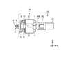
図3は、本実施形態に係る第1駆動装置9Xの一例を示す平面図である。図1、図2、及び図3に示すように、第1駆動装置9Xは、ベース部材2に支持され、テーブル1をX軸方向に移動するための動力を発生する第1アクチュエータ7Xと、テーブル1と連結され、第1アクチュエータ7Xの作動によりX軸と平行な第1駆動軸DXに沿って移動する第1可動部材8Xと、を有する。
FIG. 3 is a plan view showing an example of the
第1アクチュエータ7Xは、カップリング10Cを介してボールねじ機構10Bと接続される。第1アクチュエータ7Xで発生した動力は、ボールねじ機構10Bを介して第1可動部材8Xに伝達される。第1駆動装置9Xのボールねじ機構10Bは、第1アクチュエータ7Xが発生する動力によって回転するボールねじと、そのボールねじの周囲に配置されたナットと、を含む。
The
第1可動部材8Xは、ベース部材2に設けられた第1ガイド部材11にX軸方向にガイドされる第1リニアベアリング21と、支持装置3を介してテーブル1に連結された第2ガイド部材12にY軸方向にガイドされる第2リニアベアリング22と、を含む。第1ガイド部材11は、X軸方向に延在するようにベース部材2に固定される。第1リニアベアリング21は、ボールねじ機構10Bのナットと接続され、第1ガイド部材11にガイドされながら第1駆動軸DXに沿って移動可能である。第2ガイド部材12は、Y軸方向に延在するように、支持装置3を介してテーブル1の+X側の端部に連結される。第2リニアベアリング22は、第1接続部材31を介して、第1リニアベアリング21に固定される。第2ガイド部材12は、第2接続部材32を介して、支持装置3に接続される。
The first
第1アクチュエータ7Xが作動すると、ボールねじ機構10Bのボールねじが回転する。これにより、第1リニアベアリング21がX軸方向に移動する。第1リニアベアリング21は、ベース部材2に設けられた第1ガイド部材11によりX軸方向にガイドされ、第1駆動軸DXに沿って移動する。第1リニアベアリング21がX軸方向に移動すると、第1支持部材31を介して第1リニアベアリング21に固定されている第2リニアベアリング22及び第2ガイド部材12が、第1リニアベアリング21と一緒にX軸方向に移動する。第2リニアベアリング22及び第2ガイド部材12がX軸方向に移動すると、第2接続部材32及び支持装置3を介して第2ガイド部材12と接続されているテーブル1は、第2ガイド部材12と一緒にX軸方向に移動する。
When the
第2駆動装置9Yは、ベース部材2に支持され、テーブル1をY軸方向に移動するための動力を発生する第2アクチュエータ7Yと、テーブル1と連結され、第2アクチュエータ7Yの作動によりY軸と平行な第2駆動軸DYに沿って移動する第2可動部材8Yと、を有する。
The
第2アクチュエータ7Yは、カップリング10Cを介してボールねじ機構10Bと接続される。第2アクチュエータ7Yで発生した動力は、ボールねじ機構10Bを介して第2可動部材8Yに伝達される。第2駆動装置9Yのボールねじ機構10Bは、第2アクチュエータ7Yが発生する動力によって回転するボールねじと、そのボールねじの周囲に配置されたナットと、を含む。
The
第2可動部材8Yは、ベース部材2に設けられた第3ガイド部材13にY軸方向にガイドされる第3リニアベアリング23と、支持装置3を介してテーブル1に連結された第4ガイド部材14にX軸方向にガイドされる第4リニアベアリング24と、を含む。第3ガイド部材13は、Y軸方向に延在するようにベース部材2に固定される。第3リニアベアリング23は、ボールねじ機構10Bのナットと接続され、第3ガイド部材13にガイドされながら第2駆動軸DYに沿って移動可能である。第4ガイド部材14は、X軸方向に延在するように、支持装置3を介してテーブル1の−Y側の端部に連結される。第4リニアベアリング24は、第3接続部材33を介して、第3リニアベアリング23に固定される。第4ガイド部材14は、第4接続部材34を介して、支持装置3に接続される。
The second
第2アクチュエータ7Yが作動すると、ボールねじ機構10Bのボールねじが回転する。これにより、第3リニアベアリング23がY軸方向に移動する。第3リニアベアリング23は、ベース部材2に設けられた第3ガイド部材13によりY軸方向にガイドされ、第2駆動軸DYに沿って移動する。第3リニアベアリング23がY軸方向に移動すると、第3支持部材33を介して第3リニアベアリング23に固定されている第4リニアベアリング24及び第4ガイド部材14が、第3リニアベアリング23と一緒にY軸方向に移動する。第4リニアベアリング24及び第4ガイド部材14がY軸方向に移動すると、第4接続部材34及び支持装置3を介して第4ガイド部材14と接続されているテーブル1は、第4ガイド部材14と一緒にY軸方向に移動する。
When the
第1駆動装置9Xの作動によりテーブル1がX軸方向に移動するとき、第4ガイド部材14と第4リニアベアリング24とがX軸方向に相対移動する。テーブル1は、第4ガイド部材14及び第4リニアベアリング24にガイドされながらX軸方向に移動する。第2駆動装置9Yの作動によりテーブル1がY軸方向に移動するとき、第2ガイド部材12と第2リニアベアリング22とがY軸方向に相対移動する。テーブル1は、第2ガイド部材12及び第2リニアベアリング22にガイドされながらX軸方向に移動する。
When the table 1 moves in the X-axis direction by the operation of the
このように、移動システム9は、第1駆動装置9Xの第1アクチュエータ7Xを作動することにより、テーブル1をX軸方向に移動することができる。また、移動システム9は、第2駆動装置9Yの第2アクチュエータ7Yを作動することにより、テーブル1をY軸方向に移動することができる。
Thus, the movement system 9 can move the table 1 in the X-axis direction by operating the
図1に示すように、第1駆動装置9Xは、Y軸方向におけるテーブル中心軸AXの位置と第1駆動軸DXの位置とが一致するように1つだけ設けられる。第2駆動装置9Yは、X軸方向におけるテーブル中心軸AXの位置と第2駆動軸DYの位置とが異なるように少なくとも2つ設けられる。
As shown in FIG. 1, only one
本実施形態において、1つの第1駆動装置9Xが、テーブル1の+X側の端部に連結される。2つの第2駆動装置9Yが、テーブル1の−Y側の端部に連結される。移動システム9は、複数(2つ)の第2駆動装置9Yの第2アクチュエータ7Yの作動量を変えて、θZ方向(回転方向)にテーブル1を移動することができる。
In the present embodiment, one first driving device 9 </ b> X is coupled to the + X side end of the table 1. Two second driving devices 9 </ b> Y are coupled to the −Y side end of the table 1. The movement system 9 can move the table 1 in the θZ direction (rotation direction) by changing the operation amount of the
本実施形態において、テーブル装置100Aは、テーブル1にテーブル中心軸AXを中心とする回転方向(θZ方向)の力を予め与える予圧装置40を備える。予圧装置40は、テーブル1にθZ方向の力を常に与え続ける。予圧装置40は、第1駆動装置9X及び第2駆動装置9Yの一方又は両方がテーブル1を移動させるための力を発生している状態において、テーブル中心軸AXを中心とする一定の方向に一定の力をテーブル1に与え続ける。予圧装置40が発生する力(予圧力)は、第1駆動装置9Xが発生する力(駆動力)及び第2駆動装置9Yが発生する力(駆動力)よりも小さい。
In the present embodiment, the
図4は、本実施形態に係る予圧装置40の一例を示す側断面図であって、図1のB−B線矢視図に相当する。
FIG. 4 is a side sectional view showing an example of the
図1及び図4に示すように、予圧装置40は、ベース部材2に支持され、テーブル1にθZ方向の力を与えるための動力を発生する予圧アクチュエータ7Pと、テーブル1と連結され、予圧アクチュエータ7Pが発生する動力によりY軸と平行な予圧駆動軸DPに沿って移動する予圧可動部材8Pと、を有する。本実施形態においては、1つの予圧装置40が、テーブル1の+Y側の端部に連結される。予圧装置40は、X軸方向におけるテーブル中心軸AXの位置と予圧駆動軸DPの位置とが異なるように設けられる。予圧装置40は、テーブル1に対して−Y方向に力を作用させることで、テーブル中心軸AXを中心とする一定の方向に一定の力をテーブル1に与える。
As shown in FIGS. 1 and 4, the
本実施形態において、予圧アクチュエータ7Pは、エアシリンダである。予圧アクチュエータ7Pのシリンダ部はベース部材2に固定される。
In the present embodiment, the
予圧可動部材8Pは、ベース部材2に設けられた第5ガイド部材15にY軸方向にガイドされる第5リニアベアリング25と、支持装置3を介してテーブル1に連結された第6ガイド部材16にX軸方向にガイドされる第6リニアベアリング26と、を含む。
The preload
第5ガイド部材15は、Y軸方向に延在するようにベース部材2に固定される。第5リニアベアリング25は、第5接続部材35を介してエアシリンダのロッド部と接続され、第5ガイド部材15にガイドされながら予圧駆動軸DPに沿って移動可能である。第6ガイド部材16は、X軸方向に延在するように、支持装置3を介してテーブル1の+Y側の端部に連結される。第6リニアベアリング26は、第5接続部材35を介して、第5リニアベアリング25に固定される。第6ガイド部材16は、第6接続部材36を介して、支持装置3に接続される。
The
予圧アクチュエータ7Pが作動すると、第5リニアベアリング25がY軸方向に移動する。第5リニアベアリング25は、ベース部材2に設けられた第5ガイド部材15によりY軸方向にガイドされ、予圧駆動軸DPに沿って移動する。第5リニアベアリング25がY軸方向に移動すると、第5支持部材35を介して第5リニアベアリング25に固定されている第6リニアベアリング26及び第6ガイド部材16が、第5リニアベアリング25と一緒にY軸方向に移動する。第6リニアベアリング26及び第6ガイド部材16がY軸方向に移動すると、第6接続部材36及び支持装置3を介して第6ガイド部材16と接続されているテーブル1は、θZ方向に移動する。
When the
また、図1及び図2に示すように、テーブル装置100Aは、テーブル1の−X側の端部と連結され、テーブル1をX軸方向にガイドする第1ガイド装置50Xと、テーブル1の+Y側の端部と連結され、テーブル1をY軸方向にガイドする第2ガイド装置50Yと、を備える。第1ガイド装置50X及び第2ガイド装置50Yは、アクチュエータのような動力源を備えない。
As shown in FIGS. 1 and 2, the
第1ガイド装置50Xは、ベース部材2に設けられた第7ガイド部材17にX軸方向にガイドされる第7リニアベアリング27と、支持装置3を介してテーブル1に連結された第8ガイド部材18にY軸方向にガイドされる第8リニアベアリング28と、を含む。第7ガイド部材17は、X軸方向に延在するようにベース部材2に固定される。第7リニアベアリング27は、第7ガイド部材17にガイドされながらX軸方向に移動可能である。第8ガイド部材18は、Y軸方向に延在するように、支持装置3を介してテーブル1の−X側の端部に連結される。第8リニアベアリング28は、第7接続部材37を介して、第7リニアベアリング27に固定される。第8ガイド部材18は、第8接続部材38を介して、支持装置3に接続される。
The
第2ガイド装置50Yは、ベース部材2に設けられた第9ガイド部材19にY軸方向にガイドされる第9リニアベアリング29と、支持装置3を介してテーブル1に連結された第10ガイド部材20にX軸方向にガイドされる第10リニアベアリング30と、を含む。第9ガイド部材19は、Y軸方向に延在するようにベース部材2に固定される。第9リニアベアリング29は、第9ガイド部材19にガイドされながらY軸方向に移動可能である。第10ガイド部材20は、X軸方向に延在するように、支持装置3を介してテーブル1の+Y側の端部に連結される。第10リニアベアリング30は、第7接続部材37を介して、第9リニアベアリング29に固定される。第10ガイド部材20は、第8接続部材38を介して、支持装置3に接続される。
The
第1駆動装置9Xの作動によりテーブル1がX軸方向に移動するとき、第10ガイド部材20と第10リニアベアリング30とがX軸方向に相対移動する。テーブル1は、第10ガイド部材20及び第10リニアベアリング30にガイドされながらX軸方向に移動する。第2駆動装置9Yの作動によりテーブル1がY軸方向に移動するとき、第8ガイド部材18と第8リニアベアリング28とがY軸方向に相対移動する。テーブル1は、第8ガイド部材18及び第8リニアベアリング28にガイドされながらY軸方向に移動する。
When the table 1 moves in the X axis direction by the operation of the
次に、支持装置3について説明する。図5は、本実施形態に係る支持装置3の一例を示す図である。以下の説明においては、テーブル1と第1駆動装置9Xの第2ガイド部材12(第2接続部材32)とを連結する支持装置3について説明する。テーブル1と第2駆動装置9Yとを連結する支持装置3、テーブル1と予圧装置40とを連結する支持装置3、テーブル1と第1ガイド装置50Xとを連結する支持装置3、及びテーブル1と第1ガイド装置50Xとを連結する支持装置3は、同様の構造であるためその説明を省略する。
Next, the
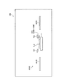
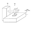
図2及び図5に示すように、支持装置3は、テーブル1の下面1Bとベース部材2の上面2Aとが間隙Gを介して対向するように、テーブル1を支持する。支持装置3は、テーブル1に固定されたロッド部材5と、ロッド部材5の周囲に配置され、Z軸と平行なロッド中心軸Jを中心にロッド部材5に対して相対回転可能であり、Z軸方向において所定値以上の荷重がテーブル1に作用したときテーブル1の下面1Bとベース部材2の上面2Aとが接触するようにZ軸方向にロッド部材5をガイドする回転軸受4と、を有する。
2 and 5, the
ロッド部材5は、テーブル1の上面1Aから上方に突出するように設けられる。ロッド部材5は、ロッド部5Lと、ロッド部5Lの上端部及び下端部のそれぞれに配置されたフランジ部5Fと、を有する。
The
回転軸受4は、実質的に円筒状である。回転軸受4は、ロッド部5Lの周囲に配置される。回転軸受4は、ケーシング3Cに支持される。第2ガイド部材12は、第2接続部材32及びケーシング3Cを介して、回転軸受4に接続される。
The
回転軸受4は、玉軸受を含む。回転軸受4は、ロッド部5Lに接触するように配置される内輪4Aと、内輪4Aの周囲に配置される外輪4Bと、内輪4Aと外輪4Bとの間に配置されるボール4Cと、を含む。本実施形態において、内輪4A、外輪4B、及びボール4Cを含む玉軸受は、鉛直方向(ロッド中心軸Jと平行な方向)に2つ配置される。
The
回転軸受4は、Z軸方向のロッド部材5の移動を許容する。回転軸受4への予圧量が調整されることにより、Z軸方向のロッド部材5の移動が許容される。ロッド部材5は、Z軸方向に移動可能に回転軸受4に支持される。本実施形態において、テーブル1は、第1駆動装置9Xに対して、Z軸方向に移動可能である。換言すれば、第1駆動装置9Xに対するZ軸方向のテーブル1の変位が許容されている。但し、回転軸受4によりZ軸方向のロッド部材5の移動が許容されることによりX軸方向のテーブル1の位置決め精度の低下が問題となる場合には、予圧が付与され半径方向に隙間が無いニードル軸受を用いて、Z軸方向のロッド部材5の移動が許容されてもよい。また、ロッド部材5の移動量が小さい場合には、回転軸受4の軸方向剛性により、Z軸方向のロッド部材5の移動が許容されてもよい。また、回転軸受4が正面組合せされ、その正面組合せされた回転軸受4からなる軸受部のθY方向の回転と、リニアベアリング11のθY方向の回転とにより、鉛直方向のロッド部材5の移動が許容されてもよい。
The
次に、本実施形態に係るテーブル装置100Aの動作の一例について説明する。テーブル1に支持されたワークSのXY平面内における位置が移動システム9により調整される。X軸方向のワークSの位置を調整する場合、移動システム9は、第1駆動装置9Xの第1アクチュエータ7Xを作動する。Y軸方向のワークSの位置を調整する場合、移動システム9は、第2駆動装置9Yの第2アクチュエータ7Yを作動する。θZ方向のワークSの位置を調整する場合、移動システム9は、2つの第2駆動装置9Yの第2アクチュエータ7Yの作動量を変えて、それら2つの第2アクチュエータ7Yを作動する。
Next, an example of the operation of the
予圧装置40は、移動システム9によりテーブル1が移動される前から、テーブル1にテーブル中心軸AXを中心とする回転方向の力を予め与え始める。すなわち、予圧装置40は、第1駆動装置9X及び第2駆動装置9Yがテーブル1を移動させるための力を発生していない状態においても、中心軸AXを中心とする一定の方向に一定の力をテーブル1に与える。また、テーブル1を移動するために移動システム9が作動した後、予圧装置40は、第1駆動装置9X及び第2駆動装置9Yの一方又は両方がテーブル1を移動させるための力を発生している状態において、中心軸AXを中心とする一定の方向に一定の力をテーブル1に与え続ける。
Before the table 1 is moved by the movement system 9, the
本実施形態においては、Y軸方向に関してテーブル中心軸AXの位置と第1駆動軸DXの位置とが一致するように、第1駆動装置9Xが設けられる。第1駆動軸DXは、第1駆動装置9Xがテーブル1に力を付与するときの力点を含む。本実施形態において、第1駆動軸DXは、第1駆動装置9Xのボールねじ機構10Bのボールねじの中心軸を含み、X軸と平行である。また、Y軸方向に関して、第1駆動軸DXの位置と回転軸受4の中心軸(ロッド中心軸J)とは一致する。Y軸方向におけるテーブル中心軸AXの位置と第1駆動軸DXの位置とが一致されることにより、テーブル1がテーブル中心軸AXを中心にθZ方向に回転しても、第1駆動装置9Xの第2リニアベアリング22と第2ガイド部材12との干渉が抑制され、第2ガイド部材12による第2リニアベアリング22の円滑なガイドが維持される。そのため、テーブル装置100Aの位置決め精度の不足が抑制される。
In the present embodiment, the
本実施形態においては、X軸方向に関してテーブル中心軸AXの位置と第2駆動軸DYの位置とが異なるように、2つの第2駆動装置9Yが設けられる。第2駆動軸DYは、第2駆動装置9Yがテーブル1に力を付与するときの力点を含む。本実施形態において、第2駆動軸DYは、第2駆動装置9Yのボールねじ機構10Bのボールねじの中心軸を含み、Y軸と平行である。X軸方向に関して、第2駆動軸DYの位置と回転軸受4の中心軸(ロッド中心軸J)とは一致する。X軸方向におけるテーブル中心軸AXの位置と第2駆動軸DYの位置とが異なることにより、テーブル1はY軸方向及びθZ方向に移動可能である。
In the present embodiment, two
テーブル1がテーブル中心軸AXを中心にθZ方向に回転したとき、Y軸方向におけるテーブル中心軸AXの位置と第1駆動軸DXとの位置がずれ(オフセットされ)、そのオフセットに起因して、第2リニアベアリング22及び第2ガイド部材12にモーメントが作用する可能性がある。本実施形態においては、テーブル1と第1駆動装置9Xとは、回転軸受4を含む支持装置3を介して連結される。そのため、テーブル1がテーブル中心軸AXを中心にθZ方向に回転しても、連結装置3におけるロッド部材5と回転軸受4との相対回転により、第2リニアベアリング22及び第2ガイド部材12に作用するモーメントが抑制される。そのため、テーブル装置100Aの位置決め誤差が低減される。
When the table 1 rotates in the θZ direction around the table center axis AX, the position of the table center axis AX and the position of the first drive axis DX in the Y axis direction are shifted (offset), and due to the offset, There is a possibility that a moment acts on the second
同様に、テーブル1と第2駆動装置9Yとは支持装置3を介して連結され、テーブル1と予圧装置40とは支持装置3を介して連結され、テーブル1と第1ガイド装置50Xとは支持装置3を介して連結され、テーブル1と第2ガイド装置50Yとは支持装置3を介して連結されているので、第4リニアベアリング24及び第4ガイド部材14に作用するモーメント、第6リニアベアリング26及び第6ガイド部材16に作用するモーメント、第8リニアベアリング28及び第8ガイド部材18に作用するモーメント、及び第10リニアベアリング30及び第2ガイド部材20に作用するモーメントが抑制される。そのため、テーブル装置100Aの位置決め誤差が低減される。
Similarly, the table 1 and the
また、テーブル装置100Aを用いるデバイスの製造工程等において、テーブル1に対して−Z方向の荷重が作用する場合がある。テーブル1に対するZ軸方向の荷重が零の場合、テーブル1の下面1Bとベース部材2の上面2Aとは、間隙Gを介して対向する。テーブル1に対するZ軸方向の荷重が所定値未満において、そのテーブル1にZ軸方向の荷重が作用した場合、間隙Gの寸法が小さくなるように、テーブル1が下降する。テーブル1に対するZ軸方向の荷重が所定値未満の場合、支持装置3は、テーブル1の下面1Bとベース部材2の上面2Aとが接触しないように、テーブル1を支持する。
In addition, a load in the −Z direction may act on the table 1 in a device manufacturing process or the like using the
テーブル1に対するZ軸方向の荷重が所定値未満で、間隙Gが形成されている状態においては、移動システム9の作動により、テーブル1は、水平方向に円滑に移動することができる。 When the load in the Z-axis direction on the table 1 is less than a predetermined value and the gap G is formed, the table 1 can move smoothly in the horizontal direction by the operation of the moving system 9.
支持装置3は、間隙Gの寸法だけ、Z軸方向に関するテーブル1の移動を許容する。間隙Gの寸法とは、テーブル1に対するZ軸方向の荷重が零のとき(無荷重のとき)の下面1Bと上面2Aとの距離である。−Z方向の荷重がテーブル1に作用したとき、テーブル1は、支持装置3にガイドされながら、下方(−Z方向)に移動する。テーブル1が下方に移動することにより、テーブル1の下面1Bは、ベース部材2の上面2Aに接触する。テーブル1に対する鉛直方向下向きの力が所定値のとき、テーブル1の下面1Bは、ベース部材2の上面2Aに接触する。支持装置3は、所定値以上の鉛直方向下向きの荷重がテーブル1に作用したとき、テーブル1の下面1Bとベース部材2の上面2Aとが接触するように、Z軸方向にテーブル1をガイドする。テーブル1の下面1Bがベース部材2の上面2Aに接触することにより、テーブル1は、ベース部材2の上面2Aに支持される。
The
間隙Gの寸法は、支持装置3に過剰な負荷(過負荷)が作用される前に下面1Bと上面2Aとが接触するように定められている。換言すれば、間隙Gの寸法の範囲内でテーブル1がZ軸方向に移動しても、支持装置3に過負荷が作用しないように、間隙Gの寸法が定められている。なお、支持装置3に過負荷が作用する状態とは、静定格荷重を超えるような荷重が支持装置3に作用する状態、及びボール4Cが内輪4A及び外輪4Bのガイド溝から外れてしまうような荷重が支持装置3に作用する状態が例示される。
The dimension of the gap G is determined so that the
所定値とは、−Z方向の荷重がテーブル1に作用し、Z軸方向に関するテーブル1の位置を支持装置3が維持できず、テーブル1が−Z方向に移動して、テーブル1の下面1Bとベース部材2の上面2Aとが接触し、間隙Gの寸法が零になるときの、テーブル1に作用する−Z方向の荷重の値をいう。テーブル1に作用する荷重が零のとき(無荷重のとき)、テーブル1は−Z方向に移動せず、Z軸方向に関するテーブル1の位置は維持され、下面1Bと上面2Aとの間隙Gは維持される。テーブル1に−Z方向の荷重が作用すると、−Z方向のテーブル1の移動が開始される。テーブル1に作用する荷重が所定値未満のとき、テーブル1は−Z方向に移動し、間隙Gの寸法は徐々に小さくなるものの、テーブル1の下面1Bとベース部材2の上面2Aとは離れている。テーブル1に作用する荷重が所定値に達すると、−Z方向に移動したテーブル1の下面1Bとベース部材2の上面2Aとが接触し、間隙Gの寸法は零になる。
The predetermined value means that a load in the −Z direction acts on the table 1, the
なお、支持装置3に過負荷が作用される前に下面1Bと上面2Aとが接触可能な間隙Gの寸法、及び荷重の所定値は、実験又はシミュレーションに基づいて予め求めることができる。求められたデータに基づいて、使用される支持装置3に適切な間隙Gの寸法、及び荷重の所定値が定められる。
Note that the size of the gap G that allows the
以上説明したように、本実施形態によれば、1つの第1駆動装置9Xと少なくとも2つの第2駆動装置9Yとによって、テーブル1は、X軸方向、Y軸方向、及びテーブル中心軸AXを中心とする回転方向の3つの方向に移動可能である。テーブル1にテーブル中心軸AXを中心とする回転方向の力を予め与える予圧装置40が設けられることにより、テーブル1には回転方向に常にモーメントが作用し、テーブル装置1Aの機構の遊びが無くなるため、位置決め精度の不足が抑制される。
As described above, according to the present embodiment, the table 1 has the X-axis direction, the Y-axis direction, and the table central axis AX by one
また、本実施形態においては、予圧装置40は、回転方向の力を発生する予圧発生部である予圧アクチュエータ7Pと、テーブル1と連結され予圧アクチュエータ7Pが発生する力によりY軸と平行な予圧駆動軸DPに沿って移動する予圧可動部材8Pと、を有し、X軸方向におけるテーブル中心軸AXの位置と予圧駆動軸DPの位置とが異なるように設けられる。これにより、予圧アクチュエータ7Pが予圧駆動軸DPに沿って発生する力によってテーブル1にモーメントを円滑に与えることができる。
In the present embodiment, the
また、本実施形態においては、第1駆動装置9X、第2駆動装置9Y、予圧装置40、第1ガイド装置50X、及び第2ガイド装置50Yはそれぞれ、支持装置3を介してテーブル1と連結される。これにより、支持装置3の回転軸受4によって、Z軸方向のテーブル1の変位が許容される。所定値以上のZ軸方向の荷重がテーブル1に作用したとき、テーブル1は、回転軸受4にガイドされて移動し、ベース部材2の上面2Aに支持される。テーブル1は、回転軸受4により、Z軸方向に真っ直ぐに移動可能である。また、テーブル1がテーブル中心軸AXを中心に回転しても、ロッド部材5と回転軸受4との相対回転により、第1駆動装置9X、第2駆動装置9Y、予圧装置40、第1ガイド装置50X、及び第2ガイド装置50Yに作用するモーメントが抑制される。そのため、テーブル装置100Aの位置決め精度の不足が抑制される。
In the present embodiment, the
なお、本実施形態においては、予圧アクチュエータ7Pがエアシリンダであることとした。予圧アクチュエータ7Pが、ボールねじ機構を介してテーブル1に予圧を与えるサーボモータでもよい。但し、サーボモータは、位置決めモードではなくトルクモードで制御されている。以下の実施形態においても同様である。
In the present embodiment, the
<第2実施形態>
第2実施形態について説明する。以下の説明において、上述の実施形態と同一又は同等の構成部分については同一の符号を付し、その説明を簡略又は省略する。
Second Embodiment
A second embodiment will be described. In the following description, the same or equivalent components as those in the above-described embodiment are denoted by the same reference numerals, and the description thereof is simplified or omitted.
図6は、本実施形態に係るテーブル装置100Bの一例を示す平面図である。本実施形態に係るテーブル装置100Bは、予圧装置40を2つ備える。本実施形態において、予圧装置40は、第1の力をテーブル1に与える第1予圧装置40Aと、第2の力をテーブル1に与える第2予圧装置40Bとを含む。第1予圧装置40Aがテーブル1に与える力と、第2予圧装置40Bがテーブル1に与える力とは、異なる。本実施形態においては、第1予圧装置40Aがテーブル1に与える第1の力は、第2予圧装置40Bがテーブル1に与える第2の力よりも大きい。例えば、第1予圧装置40Aのシリンダを第2予圧装置40Bのシリンダよりも大きくすることによって、第1予圧装置40Aがテーブル1に与える第1の力を、第2予圧装置40Bがテーブル1に与える第2の力よりも大きくすることができる。また、第1予圧装置40Aの空気圧を第2予圧装置40Bの空気圧よりも大きくすることによって、第1予圧装置40Aがテーブル1に与える第1の力を、第2予圧装置40Bがテーブル1に与える第2の力よりも大きくすることができる。
FIG. 6 is a plan view showing an example of the
X軸方向におけるテーブル中心軸AXの位置と、第1予圧装置40Aの予圧駆動軸DPの位置とは、異なる。X軸方向におけるテーブル中心軸AXの位置と、第2予圧装置40Bの予圧駆動軸DPの位置とは、異なる。本実施形態において、第1予圧装置40A及び第2予圧装置40Bは、テーブル1の+Y側の端部に連結される。第1予圧装置40Aはテーブル中心軸AXよりも+X側のテーブル1の端部に連結され、第1予圧装置40Aはテーブル中心軸AXよりも−X側のテーブル1の端部に連結される。
The position of the table center axis AX in the X-axis direction is different from the position of the preload drive shaft DP of the
以上説明したように、本実施形態によれば、予圧装置40は、X軸方向におけるテーブル中心軸AXの位置と予圧駆動軸DPの位置とが異なるように少なくとも2つ設けられ、それら2つの予圧装置40がテーブル1に与える力は、異なる。これにより、2つの予圧装置40によってテーブル1の異なる位置に異なる力を付与可能なので、テーブル1にモーメントを付与することでθZ方向におけるテーブル1の位置決め精度の不足を抑制することができる。
As described above, according to the present embodiment, at least two
また、本実施形態によれば、2つの予圧装置40がテーブル1の+Y側の端部に連結され、2つの第2駆動装置9Yがテーブル1の−Y側の端部に連結されている。また、X軸方向において、予圧駆動軸DPの位置と第2駆動軸DYの位置とが一致する。これにより、テーブル1がX軸方向及びY軸方向の少なくとも一方に移動するときの、θZ方向におけるテーブル1の位置決め誤差が抑制される。
Further, according to the present embodiment, the two
<第3実施形態>
第3実施形態について説明する。以下の説明において、上述の実施形態と同一又は同等の構成部分については同一の符号を付し、その説明を簡略又は省略する。
<Third Embodiment>
A third embodiment will be described. In the following description, the same or equivalent components as those in the above-described embodiment are denoted by the same reference numerals, and the description thereof is simplified or omitted.
図7は、本実施形態に係るテーブル装置100Cの一例を示す平面図である。テーブル装置100Cは、1つの第1駆動装置9Xと、2つの第2駆動装置9Yと、1つの予圧装置40とを備える。
FIG. 7 is a plan view showing an example of the
第1駆動装置9Xは、X軸方向のテーブル1の一方の端部(+X側の端部)に連結され、予圧装置40は、X軸方向のテーブル1の他方の端部(−X側の端部)に連結される。第1駆動装置9Xは、その第1駆動装置9Xの第1駆動軸DXがX軸と平行となるように配置される。予圧装置40は、その予圧装置40の予圧駆動軸DPがX軸と平行となるように配置される。
The
2つの第2駆動装置9Yのうち、一方の第2駆動装置9Yは、Y軸方向のテーブル1の一方の端部(+Y側の端部)に連結され、他方の第2駆動装置9Yは、Y軸方向のテーブル1の他方の端部(−Y側の端部)に連結される。一方の第2駆動装置9Yは、その第2駆動装置9Yの第2駆動軸DYがY軸と平行となるように配置される。他方の第2駆動装置9Yは、その第2駆動装置9Yの第2駆動軸DYがY軸と平行となるように配置される。
Of the two
Y軸方向におけるテーブル中心軸AXの位置と、第1駆動装置9Xの第1駆動軸DXの位置とは、異なる。Y軸方向におけるテーブル中心軸AXの位置と、予圧装置40の予圧駆動軸DPの位置とは、異なる。本実施形態においては、第1駆動装置9Xは、テーブル中心軸AXよりも−Y側のテーブル1の端部に連結され、予圧装置40は、テーブル中心軸AXよりも+Y側のテーブル1の端部に連結される。Y軸方向において、テーブル中心軸AXと第1駆動装置9Xの第1駆動軸DXとの距離は、テーブル中心軸AXと予圧装置40の予圧駆動軸DPとの距離と等しい。第1駆動装置9Xと予圧装置40とは、テーブル中心軸AXを基準として点対称の関係になるように配置される。
The position of the table center axis AX in the Y-axis direction is different from the position of the first drive axis DX of the
X軸方向におけるテーブル中心軸AXの位置と、一方の第2駆動装置9Yの第2駆動軸DYの位置とは、異なる。Y軸方向におけるテーブル中心軸AXの位置と、他方の第2駆動装置9Yの第2駆動軸DYの位置とは、異なる。本実施形態においては、一方の第2駆動装置9Yは、テーブル中心軸AXよりも+X側のテーブル1の端部に連結され、他方の第2駆動装置9Yは、テーブル中心軸AXよりも−X側のテーブル1の端部に連結される。X軸方向における、テーブル中心軸AXと一方の第2駆動装置9Yの第2駆動軸DYとの距離は、テーブル中心軸AXと他方の第2駆動装置9Yの第2駆動軸DYとの距離と等しい。一方の第2駆動装置9Yと他方の第2駆動装置9Yとは、テーブル中心軸AXを基準として点対称の関係になるように配置される。
The position of the table center axis AX in the X-axis direction is different from the position of the second drive axis DY of one
また、Y軸方向におけるテーブル中心軸AXと第1駆動装置9Xの第1駆動軸DXとの距離と、Y軸方向におけるテーブル中心軸AXと予圧装置40の予圧駆動軸DPとの距離と、X軸方向におけるテーブル中心軸AXと一方の第2駆動装置9Yの第2駆動軸DYとの距離と、X軸方向におけるテーブル中心軸AXと他方の第2駆動装置9Yの第2駆動軸DYとの距離とは、等しい。
Further, the distance between the table center axis AX and the first drive axis DX of the
第1駆動装置9Xとテーブル1との連結部を連結部J1、予圧装置40とテーブル1との連結部を連結部J2、一方の第2駆動装置9Yとテーブル1との連結部を連結部J3、他方の第2駆動装置9Yとテーブル1との連結部を連結部J4、としたとき、XY平面内におけるテーブル中心軸AXと連結部J1との距離と、テーブル中心軸AXと連結部J2との距離と、テーブル中心軸AXと連結部J3との距離と、テーブル中心軸AXと連結部J4との距離とは、等しい。なお、テーブル1との連結部J1,J2,J3,J4とは、図5等に示したように、支持装置3とテーブル1との連結部をいう。更に具体的には、テーブル1との連結部J1、J2,J3,J4とは、支持装置3のロッド部材5の下側のフランジ部5Fとテーブル1との連結部をいう。
A connecting portion between the
以上説明したように、本実施形態によれば、第1駆動装置9Xと、予圧装置40と、一方の第2駆動装置9Yと、他方の第2駆動装置9Yとが、テーブル中心軸AXを基準として点対称の関係になるように配置される。そのため、Z軸方向の負荷がテーブル1に均等に作用する。したがって、テーブル1の位置決め精度の不足が抑制される。
As described above, according to the present embodiment, the
<第4実施形態>
第4実施形態について説明する。以下の説明において、上述の実施形態と同一又は同等の構成部分については同一の符号を付し、その説明を簡略又は省略する。
<Fourth embodiment>
A fourth embodiment will be described. In the following description, the same or equivalent components as those in the above-described embodiment are denoted by the same reference numerals, and the description thereof is simplified or omitted.
図8は、本実施形態に係るテーブル装置100Dの一例を示す平面図である。テーブル装置100Dは、予圧装置40を2つ備える。予圧装置40は、第1の力をテーブル1に与える第1予圧装置40Aと、第2の力をテーブル1に与える第2予圧装置40Bとを含む。なお、本実施形態において、予圧装置40は、その予圧装置40の予圧駆動軸DPがX軸と平行となるように配置される。
FIG. 8 is a plan view showing an example of the
2つの予圧装置40のうち、第1予圧装置40Aは、X軸方向のテーブル1の一方の端部(+X側の端部)に連結され、第2予圧装置40Bは、X軸方向のテーブル1の他方の端部(−X側の端部)に連結される。
Of the two
Y軸方向におけるテーブル中心軸AXの位置と、第1予圧装置40Aの予圧駆動軸DPの位置とは、異なる。Y軸方向におけるテーブル中心軸AXの位置と、第2予圧装置40Bの予圧駆動軸DPの位置とは、異なる。本実施形態においては、第1予圧装置40Aと第2予圧装置40Bとは対向するように配置され、第1予圧装置40A及び第2予圧装置40Bの両方が、テーブル中心軸AXよりも+Y側のテーブル1の端部に連結される。Y軸方向において、第1予圧装置40Aの予圧駆動軸DPの位置と、第2予圧装置40Bの予圧駆動軸DPの位置とは、一致する。
The position of the table center axis AX in the Y-axis direction is different from the position of the preload drive shaft DP of the
以上説明したように、本実施形態によれば、第1予圧装置40Aは、テーブル1の+X側の端部に連結され、第2予圧装置40Bは、テーブル1の−X側の端部に連結される。これにより、2つの予圧装置40によってテーブル中心軸AXに対して対称となるテーブル1の異なる位置に力を付与可能なので、テーブル1にモーメントを付与することでθZ方向におけるテーブル1の位置決め精度の不足を抑制することができる。
As described above, according to the present embodiment, the
<第5実施形態>
第5実施形態について説明する。以下の説明において、上述の実施形態と同一又は同等の構成部分については同一の符号を付し、その説明を簡略又は省略する。
<Fifth Embodiment>
A fifth embodiment will be described. In the following description, the same or equivalent components as those in the above-described embodiment are denoted by the same reference numerals, and the description thereof is simplified or omitted.
図9は、本実施形態に係るテーブル装置100Eの一例を示す平面図である。図10は、本実施形態に係るテーブル装置100Eの一例を示す側断面図である。
FIG. 9 is a plan view showing an example of the
本実施形態においては、テーブル装置100Eの少なくとも一部がチャンバ装置200の内部空間に配置される。本実施形態においては、テーブル1、第1可動部材8Xの少なくとも一部、第2可動部材8Yの少なくとも一部、及び予圧可動部材8Pの少なくとも一部が、チャンバ装置200の内部空間に配置される。
In the present embodiment, at least a part of the
第1アクチュエータ7X、第2アクチュエータ7Y、予圧アクチュエータ7P、第1ガイド装置50X、及び第2ガイド装置50Yは、チャンバ装置200の外部空間に配置される。
The
チャンバ装置200は、内部空間の環境を制御する環境制御システムを含む。内部空間の環境は、チャンバ装置200内外の圧力が変わるような、内部空間のガスの種類、温度、湿度、圧力(真空度を含む)、及びクリーン度の少なくとも一つを含む。
The
環境制御システムによって、チャンバ装置200の内部空間は、例えば真空状態に制御される。また、環境制御システムによって、チャンバ装置200の内部空間は、例えば一定温度に制御される。
By the environmental control system, the internal space of the
チャンバ装置200は、内部空間と外部空間とを結ぶ複数の開口200Kを有する。複数の開口200Kに、第1駆動装置9X、第2駆動装置9Y、予圧装置40、第1ガイド装置50X、及び第2ガイド装置50Yが配置される。
The
チャンバ装置200は、開口200Kに配置されたべローズ250と、ベローズ250を支持する支持装置260とを備えている。べローズ250は、チャンバ装置200と、第1可動部材8Xとを連結するように設けられる。べローズ250は、チャンバ装置200と、第2可動部材8Yとを連結するように設けられる。べローズ250は、チャンバ装置200と、予圧可動部材8Pとを連結するように設けられる。これにより、開口200Kが塞がれ、内部空間と外部空間とのガスの流通が抑制される。
The
以上説明したように、本実施形態によれば、少なくともテーブル1が配置される内部空間を有するチャンバ装置200が設けられるので、環境が制御されたチャンバ装置200の内部空間において、テーブル1に支持されたワークSが処理される。アクチュエータ7X,7Y,7Pは、チャンバ装置200の外部空間に配置されているので、例えば、アクチュエータ7X,7Y,7Pから熱が発生しても、その熱がテーブル1及びワークSに及ぼす影響が抑制される。また、アクチュエータ7X,7Y,7Pから異物が発生しても、その異物がテーブル1及びワークSに及ぼす影響が抑制される。また、テーブル装置100Iの全部がチャンバ装置200の内部空間に収容されず、テーブル1、ガイド部材18,20,70、リニアベアリング19,21,71、及び連結装置3などがチャンバ装置200の内部空間に収容され、アクチュエータ7X,7Y,7Pがチャンバ装置200の外部空間に配置されることによって、チャンバ装置200の大型化が抑制される。
As described above, according to the present embodiment, the
<第6実施形態>
第6実施形態について説明する。以下の説明において、上述の実施形態と同一又は同等の構成部分については同一の符号を付し、その説明を簡略又は省略する。
<Sixth Embodiment>
A sixth embodiment will be described. In the following description, the same or equivalent components as those in the above-described embodiment are denoted by the same reference numerals, and the description thereof is simplified or omitted.
図11は、本実施形態に係るテーブル装置100Fの一例を示す平面図である。本実施形態において、予圧装置40Fは、予圧アクチュエータを有しない。べローズ250による弾性力によって、テーブル1にテーブル中心軸AXを中心とする回転方向の力が与えられる。
FIG. 11 is a plan view showing an example of the
また、べローズ250は、第1の弾性力をテーブル1に付与する第1べローズ250Aと、第2の弾性力をテーブル1に付与する第2べローズ250Bとを含む。X軸方向におけるテーブル中心軸AXの位置と、第1べローズ250Aの位置及び第2べローズ250Bの位置とは異なる。第1べローズ250Aがテーブル1に与える力と、第2べローズ250Bがテーブル1に与える力とは、異なる。例えば、第1べローズ250Aの面積と、第2べローズ250Bの面積とを異ならせることによって、第1べローズ250Aがテーブル1に与える力と、第2べローズ250Bがテーブル1に与える力とを異ならせることができる。なお、べローズ250は、開口200Kに配置される筒状部材であり、べローズ250の面積とは、その筒状部材であるべローズ250の開口面積をいう。
The bellows 250 includes a first bellows 250 </ b> A that applies a first elastic force to the table 1 and a second bellows 250 </ b> B that applies a second elastic force to the table 1. The position of the table center axis AX in the X-axis direction is different from the position of the
以上説明したように、予圧装置40Fがテーブル1に与える力は、予圧アクチュエータが発生する動力でなくてもよく、べローズ250が発生する弾性力でもよい。
As described above, the force applied to the table 1 by the
<第7実施形態>
第7実施形態について説明する。以下の説明において、上述の実施形態と同一又は同等の構成部分については同一の符号を付し、その説明を簡略又は省略する。
<Seventh embodiment>
A seventh embodiment will be described. In the following description, the same or equivalent components as those in the above-described embodiment are denoted by the same reference numerals, and the description thereof is simplified or omitted.
図12は、本実施形態に係るテーブル装置100A(100B〜100F)を備えるフラットパネルディスプレイ製造装置500の一例を示す図である。フラットパネルディスプレイ製造装置500は、フラットパネルディスプレイの製造工程の少なくとも一部において使用される。フラットパネルディスプレイは、液晶ディスプレイ、プラズマディスプレイ、及び有機ELディスプレイの少なくとも一つを含む。
FIG. 12 is a diagram illustrating an example of a flat panel
フラットパネルディスプレイ製造装置500は、フラットパネルディスプレイを製造するためのワークSを搬送可能な搬送装置600を含む。搬送装置600は、本実施形態に係るテーブル装置100Aを含む。
The flat panel
なお、図12においては、テーブル装置100Aを簡略して図示する。ワークSは、テーブル1に支持される。
In FIG. 12, the
本実施形態において、ワークSは、フラットパネルディスプレイを製造するための基板である。ワークSからフラットパネルディスプレイが製造される。ワークSは、ガラス板を含んでもよい。液晶ディスプレイが製造される場合、ワークSは、TFT基板を含んでもよいし、カラーフィルタ基板を含んでもよい。 In the present embodiment, the workpiece S is a substrate for manufacturing a flat panel display. A flat panel display is manufactured from the workpiece S. The workpiece S may include a glass plate. When a liquid crystal display is manufactured, the workpiece S may include a TFT substrate or a color filter substrate.
フラットパネルディスプレイ製造装置500は、処理位置(目標位置)PJ1に配置されたワークSを使って、フラットパネルディスプレイを製造するための処理を行う。テーブル装置100Aは、テーブル1に支持されたワークSを処理位置PJ1に配置する。搬送装置600は、テーブル装置100Aのテーブル1にワークSを搬送(搬入)可能な搬入装置601と、テーブル1からワークSを搬送(搬出)可能な搬出装置602とを含む。搬入装置601によって、処理前のワークSがテーブル1に搬送(搬入)される。テーブル装置100Aによって、テーブル1に支持されたワークSが処理位置PJ1まで搬送される。搬出装置602によって、処理後のワークSがテーブル1から搬送(搬出)される。
The flat panel
テーブル装置100Aは、テーブル1を移動して、テーブル1に支持されたワークSを処理位置PJ1に移動する。テーブル装置100Aは、テーブル1に支持されたワークSを高い位置決め精度で処理位置PJ1に配置可能である。
The
例えば、フラットパネルディスプレイ製造装置500が、2枚の基板を貼り合せる貼り合せ装置を含む場合、テーブル1に支持されているワークSは、2枚の基板のうち一方の基板を含む。処理位置PJ1は、一方の基板が他方の基板と貼り合せられる貼り合せ位置を含む。貼り合せ位置に配置されたテーブル1の一方の基板に、他方の基板が押し付けられる。
For example, when the flat panel
本実施形態において、フラットパネルディスプレイ製造装置500は、他方の基板を保持する基板ホルダ501を有する。基板ホルダ501は、テーブル1に支持されたワークS(一方の基板)を処理する処理部として機能する。基板ホルダ501は、貼り合せ位置に配置されている一方の基板と、基板ホルダ501に保持されている他方の基板とを対向させる。基板ホルダ501は、テーブル1に支持されている一方の基板に他方の基板を押し付けるように、下方に移動する。これにより、2枚の基板が貼り合せられる。
In the present embodiment, the flat panel
処理位置PJ1においてワークSが処理された後、その処理後のワークSが搬出装置602によってテーブル1から搬送される。搬出装置602によって搬送(搬出)されたワークSは、後工程を行う処理装置に搬送される。
After the workpiece S is processed at the processing position PJ1, the processed workpiece S is conveyed from the table 1 by the carry-out
本実施形態においては、テーブル装置100Aは、ワークSを処理位置PJ1に配置可能である。また、テーブル1の位置決め精度の不足が抑制されている。そのため、不良な製品(フラットパネルディスプレイ)の発生が抑制される。
In the present embodiment, the
なお、テーブル装置100A(100B〜100F)が、半導体製造装置に使用されてもよい。半導体製造装置は、例えば、投影光学系を介してワークSにデバイスパターンを形成する露光装置を含む。露光装置において、処理位置PJ1は、投影光学系の像面位置(露光位置)を含む。投影光学系は、テーブル1に支持されたワークSを露光処理する処理部として機能する。処理位置PJ1にワークSが配置されることにより、半導体製造装置は、投影光学系を介して、ワークSにデバイスパターンを形成可能である。
Note that the
なお、半導体製造装置が、ワークSに膜を形成する成膜装置を含んでもよい。半導体製造装置が成膜装置を含む場合、処理位置PJ1は、膜を形成するための材料が供給される供給位置(成膜位置)を含む。材料を供給する供給部が、テーブル1に支持されたワークSの成膜処理を行う処理部として機能する。処理位置PJ1にワークSが配置されることにより、デバイスパターンを形成するための膜がワークSに形成される。 The semiconductor manufacturing apparatus may include a film forming apparatus that forms a film on the workpiece S. When the semiconductor manufacturing apparatus includes a film forming apparatus, the processing position PJ1 includes a supply position (film forming position) to which a material for forming a film is supplied. The supply unit that supplies the material functions as a processing unit that performs the film forming process of the workpiece S supported by the table 1. By disposing the workpiece S at the processing position PJ1, a film for forming a device pattern is formed on the workpiece S.
<第8実施形態>
第8実施形態について説明する。図13は、本実施形態に係るテーブル装置100A(100B〜100F)を備える精密機械700の一例を示す図である。本実施形態においては、精密機械700が、精密機器のようなワークを精密に測定する精密測定機である例について説明する。
<Eighth Embodiment>
An eighth embodiment will be described. FIG. 13 is a diagram illustrating an example of a
精密測定機700は、ワークS2を測定する。ワークS2は、例えば、フラットパネルディスプレイ製造装置500により製造されたフラットパネルディスプレイ、及び上述の半導体製造装置により製造された半導体デバイスの少なくとも一方を含んでもよい。精密測定機700は、ワークS2を搬送可能な搬送装置600Bを含む。搬送装置600Bは、本実施形態に係るテーブル装置100Aを含む。
The
なお、図13において、テーブル装置100Aを簡略して図示する。ワークS2は、テーブル1に支持される。
In FIG. 13, the
精密測定機700は、測定位置(目標位置)PJ2に配置されたワークS2の測定を行う。テーブル装置100Aは、テーブル1に支持されたワークS2を測定位置PJ2に配置する。搬送装置600Bは、テーブル装置100Aのテーブル1にワークS2を搬送(搬入)可能な搬入装置601Bと、テーブル1からワークS2を搬送(搬出)可能な搬出装置602Bとを含む。搬入装置601Bによって、測定前のワークS2がテーブル1に搬送(搬入)される。テーブル装置100Aによって、テーブル1に支持されたワークS2が測定位置PJ2まで搬送される。搬出装置602Bによって、測定後のワークS2がテーブル1から搬送(搬出)される。
The
テーブル装置100Aは、テーブル1を移動して、テーブル1に支持されたワークS2を測定位置PJ2に移動する。テーブル装置100Aは、テーブル1に支持されたワークS2を高い位置決め精度で測定位置PJ2に配置可能である。
The
本実施形態において、精密測定機700は、検出光を用いてワークS2の測定を光学的に行う。精密測定機700は、検出光を射出可能な照射装置701と、照射装置701から射出され、ワークS2で反射した検出光の少なくとも一部を受光可能な受光装置702とを含む。本実施形態において、測定位置PJ2は、検出光の照射位置を含む。照射装置701及び受光装置702は、テーブル1に支持されたワークS2を処理する処理部として機能する。本実施形態において、照射装置701及び受光装置702は、テーブル1に支持されたワークS2を測定する測定部として機能する。測定位置PJ2にワークS2が配置されることにより、ワークS2の状態が光学的に測定される。
In the present embodiment, the
測定位置PJ2においてワークS2の測定が行われた後、その測定後のワークS2が搬出装置602Bによってテーブル1から搬送される。
After the workpiece S2 is measured at the measurement position PJ2, the workpiece S2 after the measurement is conveyed from the table 1 by the carry-out
本実施形態においては、テーブル装置100Aは、ワークS2を測定位置(目標位置)PJ2に配置可能であるため、測定不良の発生を抑制できる。すなわち、精密測定機700は、ワークS2が不良であるか否かを良好に判断することができる。これにより、例えば不良なワークS2が後工程に搬送されたり、出荷されたりすることが抑制される。また、精密測定機700は、テーブル1によって測定位置PJ2に配置されたワークS2を測定できるので、そのワークS2の測定を精密に行うことができる。
In the present embodiment, the
なお、三次元測定装置が、本実施形態に係るテーブル装置100Aを備えてもよいし、テーブル装置100Aを含む搬送装置を備えてもよい。測定対象のワークがテーブル1に支持されることにより、三次元測定装置は、目標位置に配置されたワークを測定できるので、そのワークの測定を精密に行うことができる。
Note that the three-dimensional measurement apparatus may include the
<第9実施形態>
第9実施形態について説明する。図14は、本実施形態に係るテーブル装置100A(100B〜100F)を備える精密機械800の一例を示す図である。本実施形態においては、精密機械800が、精密加工を実施可能な精密加工機である例について説明する。
<Ninth Embodiment>
A ninth embodiment will be described. FIG. 14 is a diagram illustrating an example of a
精密加工機800は、ワークS3を加工する。精密加工機800は、マシニングセンタを含み、テーブル装置100Aと、加工ヘッド801とを有する。加工ヘッド801が、テーブル装置100Aのテーブル1に支持されたワークS3を処理する処理部として機能する。本実施形態においては、加工ヘッド801が、テーブル装置100Aのテーブル1に支持されたワークS3を加工する加工部として機能する。加工ヘッド801は、加工工具を有し、テーブル装置100Aのテーブル1に支持されたワークS3を加工工具で加工する。加工ヘッド801は、ワークS3を切削する機構である。加工ヘッド801は、テーブル1の移動方向と直交するZ軸方向に加工工具を移動させる。
The
精密加工機800は、テーブル装置100AでワークS3をXY平面内において移動させ、加工ヘッド801をZ軸方向に移動させることで、加工工具とワークS3とを相対的に移動させることができる。
The
精密加工機800は、加工位置(目標位置)に配置されたテーブル1上のワークS3を加工できるので、そのワークS3の加工を精密に行うことができる。
Since the
なお、本実施形態においては、テーブル1がXY平面内(水平面内)に移動することとした。本実施形態において、テーブル1がXY平面に対して傾斜する方向に移動されてもよい。すなわち、XY平面は、水平面と平行でもよいし、水平面に対して傾斜していてもよい。 In the present embodiment, the table 1 is moved in the XY plane (in the horizontal plane). In the present embodiment, the table 1 may be moved in a direction inclined with respect to the XY plane. That is, the XY plane may be parallel to the horizontal plane or may be inclined with respect to the horizontal plane.
1 テーブル
1A 上面
1B 下面
2 ベース部材
2A 上面(ガイド面)
3 支持装置
3C ケーシング
4 回転軸受
4A 内輪
4B 外輪
4C ボール
5 ロッド部材
5F フランジ部
5L ロッド部
7X 第1アクチュエータ
7Y 第2アクチュエータ
7P 予圧アクチュエータ
8X 第1可動部材
8Y 第2可動部材
8P 予圧可動部材
9 移動システム
9X 第1駆動装置
9Y 第2駆動装置
10B ボールねじ機構
10C カップリング
11 第1ガイド部材
12 第2ガイド部材
13 第3ガイド部材
14 第4ガイド部材
15 第5ガイド部材
16 第6ガイド部材
17 第7ガイド部材
18 第8ガイド部材
19 第9ガイド部材
20 第10ガイド部材
21 第1リニアベアリング
22 第2リニアベアリング
23 第3リニアベアリング
24 第4リニアベアリング
25 第5リニアベアリング
26 第6リニアベアリング
27 第7リニアベアリング
28 第8リニアベアリング
29 第9リニアベアリング
30 第10リニアベアリング
31 第1接続部材
32 第2接続部材
33 第3接続部材
34 第4接続部材
35 第5接続部材
36 第6接続部材
37 第7接続部材
38 第8接続部材
40 予圧装置
40F 予圧装置
50X 第1ガイド装置
50Y 第2ガイド装置
100A テーブル装置
100B テーブル装置
100C テーブル装置
100D テーブル装置
100E テーブル装置
200 チャンバ装置
200K 開口
250 ベローズ
260 支持装置
500 フラットパネルディスプレイ製造装置
700 精密機械(精密測定機)
800 精密機械(精密加工機)
AX テーブル中心軸
DP 予圧駆動軸
DX 第1駆動軸
DY 第2駆動軸
G 間隙
S ワーク
1 Table
3
800 Precision machine (Precision processing machine)
AX Table center axis DP Preload drive axis DX First drive axis DY Second drive axis G Gap S Workpiece
Claims (14)
前記ベース部材に支持され、前記ガイド面と平行な所定面内の第1軸と平行な第1軸方向、前記第1軸と直交する前記所定面内の第2軸と平行な第2軸方向、及び前記所定面と直交する第3軸と平行なテーブル中心軸を中心に回転可能なテーブルと、
前記ベース部材に支持された第1アクチュエータと、前記テーブルと連結され前記第1アクチュエータの作動により前記第1軸と平行な第1駆動軸に沿って移動する第1可動部材と、を有し、前記第2軸方向における前記テーブル中心軸の位置と前記第1駆動軸の位置とが一致するように1つだけ設けられた第1駆動装置と、
前記ベース部材に支持された第2アクチュエータと、前記テーブルと連結され前記第2アクチュエータの作動により前記第2軸と平行な第2駆動軸に沿って移動する第2可動部材と、をそれぞれ有し、前記第1軸方向における前記テーブル中心軸の位置と前記第2駆動軸の位置とが異なるように少なくとも2つ設けられた第2駆動装置と、
前記テーブルに前記テーブル中心軸を中心とする回転方向の力を予め与える予圧装置と、
を備えるテーブル装置。 A base member having a guide surface;
A first axial direction parallel to a first axis in a predetermined plane parallel to the guide surface and supported by the base member, and a second axial direction parallel to a second axis in the predetermined plane orthogonal to the first axis And a table rotatable around a table central axis parallel to a third axis orthogonal to the predetermined plane;
A first actuator supported by the base member; and a first movable member connected to the table and moving along a first drive shaft parallel to the first shaft by the operation of the first actuator; A first drive device provided only one so that the position of the table center axis in the second axis direction and the position of the first drive axis coincide;
A second actuator supported by the base member; and a second movable member that is connected to the table and moves along a second drive shaft that is parallel to the second shaft by the operation of the second actuator. A second drive device provided with at least two so that the position of the table central axis and the position of the second drive shaft in the first axis direction are different from each other;
A preload device that preliminarily applies a force in a rotational direction about the table central axis to the table;
A table device comprising:
請求項1に記載のテーブル装置。 The preload device includes a preload generator that generates a force in the rotational direction, and a preload movable member that is connected to the table and moves along a preload drive shaft that is parallel to the second shaft by the force generated by the preload generator. And provided so that the position of the table central axis and the position of the preload drive shaft in the first axis direction are different from each other.
The table apparatus according to claim 1.
少なくとも2つの前記予圧装置が前記テーブルに与える力は、異なる、
請求項2に記載のテーブル装置。 At least two preload devices are provided such that the position of the table central axis and the position of the preload drive shaft in the first axis direction are different,
The force applied to the table by at least two of the preload devices is different,
The table device according to claim 2.
請求項3に記載のテーブル装置。 Of the at least two preload devices, one preload device is connected to one end of the table in the second axial direction, and one preload device is connected to the other end of the table in the second axial direction. Connected to the end of the
The table apparatus according to claim 3.
請求項2から請求項4のいずれか一項に記載のテーブル装置。 The preload generator includes a preload actuator supported by the base member.
The table apparatus as described in any one of Claims 2-4.
前記チャンバ装置と前記予圧可動部材とを連結するべローズと、を備え、
前記予圧発生部は、前記べローズを含む、
請求項2から請求項4のいずれか一項に記載のテーブル装置。 A chamber apparatus having an internal space in which at least a part of the table and the preload movable member is disposed;
A bellows connecting the chamber device and the preload movable member;
The preload generator includes the bellows,
The table apparatus as described in any one of Claims 2-4.
前記支持装置は、前記テーブルに固定されたロッド部材と、前記ロッド部材の周囲に配置され前記第3軸と平行なロッド中心軸を中心に前記ロッド部材に対して相対回転可能であり、前記第3軸と平行な第3軸方向において所定値以上の荷重が前記テーブルに作用したとき前記テーブルの下面と前記ベース部材のガイド面とが接触するように前記第3軸方向に前記ロッド部材をガイドする回転軸受と、を有する、
請求項2から請求項6のいずれか一項に記載のテーブル装置。 Each of the first movable member, the second movable member, and the preload movable member includes a support device that supports the table such that the lower surface of the table and the guide surface of the base member face each other with a gap therebetween. ,
The support device is rotatable relative to the rod member about a rod member fixed to the table, a rod central axis arranged around the rod member and parallel to the third axis, The rod member is guided in the third axis direction so that the lower surface of the table comes into contact with the guide surface of the base member when a load of a predetermined value or more is applied to the table in a third axis direction parallel to the three axes. A rotating bearing
The table apparatus as described in any one of Claims 2-6.
請求項7に記載のテーブル装置。 The first movable member includes a first linear bearing guided in a first axial direction by a first guide member provided on the base member, and a second guide member coupled to the table via the support device. And a second linear bearing guided in the second axial direction.
The table device according to claim 7.
請求項7又は請求項8に記載のテーブル装置。 The second movable member includes a third linear bearing guided in a second axial direction by a third guide member provided on the base member, and a fourth guide member connected to the table via the support device. And a fourth linear bearing guided in the first axial direction.
The table device according to claim 7 or 8.
請求項7から請求項9のいずれか一項に記載のテーブル装置。 The preload movable member includes a fifth linear bearing guided in the second axial direction by a fifth guide member provided on the base member, and a sixth guide member coupled to the table via the support device. A sixth linear bearing guided in the first axial direction,
The table apparatus as described in any one of Claims 7-9.
請求項1から請求項10のいずれか一項に記載のテーブル装置。 Of the at least two second drive devices, one of the second drive devices is connected to one end of the table in the second axial direction, and one of the second drive devices is connected to the second shaft. Connected to the other end of the table in the direction,
The table apparatus as described in any one of Claims 1-10.
前記テーブル装置の前記テーブルに支持されたワークの位置を決定する、
位置決め装置。 A table apparatus according to any one of claims 1 to 11, comprising:
Determining a position of a work supported by the table of the table device;
Positioning device.
前記テーブルに支持されたワークを処理する処理部と、
を備えるフラットパネルディスプレイ製造装置。 The table device according to any one of claims 1 to 11,
A processing unit for processing the work supported by the table;
A flat panel display manufacturing apparatus.
前記テーブルに支持されたワークを処理する処理部と、
を備える精密機械。 The table device according to any one of claims 1 to 11,
A processing unit for processing the work supported by the table;
Precision machine equipped with.
Priority Applications (1)
| Application Number | Priority Date | Filing Date | Title |
|---|---|---|---|
| JP2016003574A JP6693132B2 (en) | 2016-01-12 | 2016-01-12 | Table device, positioning device, flat panel display manufacturing device, and precision machine |
Applications Claiming Priority (1)
| Application Number | Priority Date | Filing Date | Title |
|---|---|---|---|
| JP2016003574A JP6693132B2 (en) | 2016-01-12 | 2016-01-12 | Table device, positioning device, flat panel display manufacturing device, and precision machine |
Publications (2)
| Publication Number | Publication Date |
|---|---|
| JP2017126601A true JP2017126601A (en) | 2017-07-20 |
| JP6693132B2 JP6693132B2 (en) | 2020-05-13 |
Family
ID=59364445
Family Applications (1)
| Application Number | Title | Priority Date | Filing Date |
|---|---|---|---|
| JP2016003574A Active JP6693132B2 (en) | 2016-01-12 | 2016-01-12 | Table device, positioning device, flat panel display manufacturing device, and precision machine |
Country Status (1)
| Country | Link |
|---|---|
| JP (1) | JP6693132B2 (en) |
Citations (6)
| Publication number | Priority date | Publication date | Assignee | Title |
|---|---|---|---|---|
| JPS5972727A (en) * | 1982-10-19 | 1984-04-24 | Matsushita Electric Ind Co Ltd | Positioning table |
| JPS61267245A (en) * | 1985-05-20 | 1986-11-26 | Fujitsu Ltd | Driving device for moving table in vacuum |
| JPH0473434U (en) * | 1990-10-31 | 1992-06-26 | ||
| JPH05259022A (en) * | 1992-03-09 | 1993-10-08 | Fujitsu Ltd | Stage mechanism |
| JPH09216137A (en) * | 1996-02-09 | 1997-08-19 | Nippon Seiko Kk | Positioning device |
| JP2011119293A (en) * | 2009-11-02 | 2011-06-16 | Bondtech Inc | Alignment device |
-
2016
- 2016-01-12 JP JP2016003574A patent/JP6693132B2/en active Active
Patent Citations (6)
| Publication number | Priority date | Publication date | Assignee | Title |
|---|---|---|---|---|
| JPS5972727A (en) * | 1982-10-19 | 1984-04-24 | Matsushita Electric Ind Co Ltd | Positioning table |
| JPS61267245A (en) * | 1985-05-20 | 1986-11-26 | Fujitsu Ltd | Driving device for moving table in vacuum |
| JPH0473434U (en) * | 1990-10-31 | 1992-06-26 | ||
| JPH05259022A (en) * | 1992-03-09 | 1993-10-08 | Fujitsu Ltd | Stage mechanism |
| JPH09216137A (en) * | 1996-02-09 | 1997-08-19 | Nippon Seiko Kk | Positioning device |
| JP2011119293A (en) * | 2009-11-02 | 2011-06-16 | Bondtech Inc | Alignment device |
Also Published As
| Publication number | Publication date |
|---|---|
| JP6693132B2 (en) | 2020-05-13 |
Similar Documents
| Publication | Publication Date | Title |
|---|---|---|
| JP5594404B1 (en) | Table device, transfer device, semiconductor manufacturing device, and flat panel display manufacturing device | |
| JP6634836B2 (en) | Table equipment, positioning equipment, flat panel display manufacturing equipment, and precision machinery | |
| JP5541398B1 (en) | Table device and transfer device | |
| JP5319154B2 (en) | Stage equipment | |
| JP2014229669A (en) | Table device, conveying device, and semiconductor manufacturing device | |
| WO2015087411A1 (en) | Processing apparatus and processing method | |
| WO2017017988A1 (en) | Table device, positioning device, flat-panel display manufacturing device, and precision machine | |
| JP6693132B2 (en) | Table device, positioning device, flat panel display manufacturing device, and precision machine | |
| JP6610083B2 (en) | Table device, positioning device, flat panel display manufacturing device, and precision machine | |
| JP6520073B2 (en) | Table device, positioning device, flat panel display manufacturing device, and precision machine | |
| JP5359009B2 (en) | Semiconductor substrate bonding equipment | |
| KR102205676B1 (en) | Positioning apparatus, lithography apparatus, and method of manufacturing article | |
| JP6318960B2 (en) | Table device, measuring device, semiconductor manufacturing device, flat panel display manufacturing device, and machine tool | |
| JP6331300B2 (en) | Table device and transfer device | |
| JP2009253227A (en) | Bonding apparatus for semiconductor substrate and manufacturing method of semiconductor device | |
| JP6398371B2 (en) | Drive device, machine tool, and semiconductor manufacturing apparatus | |
| JP2016032037A (en) | Table device, measuring apparatus, semiconductor manufacturing apparatus, flat panel display manufacturing apparatus, and machine tool |
Legal Events
| Date | Code | Title | Description |
|---|---|---|---|
| A621 | Written request for application examination |
Free format text: JAPANESE INTERMEDIATE CODE: A621 Effective date: 20181115 |
|
| A977 | Report on retrieval |
Free format text: JAPANESE INTERMEDIATE CODE: A971007 Effective date: 20190819 |
|
| A131 | Notification of reasons for refusal |
Free format text: JAPANESE INTERMEDIATE CODE: A131 Effective date: 20190910 |
|
| A521 | Request for written amendment filed |
Free format text: JAPANESE INTERMEDIATE CODE: A523 Effective date: 20191108 |
|
| TRDD | Decision of grant or rejection written | ||
| A01 | Written decision to grant a patent or to grant a registration (utility model) |
Free format text: JAPANESE INTERMEDIATE CODE: A01 Effective date: 20200317 |
|
| A61 | First payment of annual fees (during grant procedure) |
Free format text: JAPANESE INTERMEDIATE CODE: A61 Effective date: 20200330 |
|
| R150 | Certificate of patent or registration of utility model |
Ref document number: 6693132 Country of ref document: JP Free format text: JAPANESE INTERMEDIATE CODE: R150 |