JP2017125933A - Image formation apparatus - Google Patents
Image formation apparatus Download PDFInfo
- Publication number
- JP2017125933A JP2017125933A JP2016004725A JP2016004725A JP2017125933A JP 2017125933 A JP2017125933 A JP 2017125933A JP 2016004725 A JP2016004725 A JP 2016004725A JP 2016004725 A JP2016004725 A JP 2016004725A JP 2017125933 A JP2017125933 A JP 2017125933A
- Authority
- JP
- Japan
- Prior art keywords
- image
- transfer
- latent image
- image forming
- forming apparatus
- Prior art date
- Legal status (The legal status is an assumption and is not a legal conclusion. Google has not performed a legal analysis and makes no representation as to the accuracy of the status listed.)
- Pending
Links
Images


Classifications
-
- G—PHYSICS
- G03—PHOTOGRAPHY; CINEMATOGRAPHY; ANALOGOUS TECHNIQUES USING WAVES OTHER THAN OPTICAL WAVES; ELECTROGRAPHY; HOLOGRAPHY
- G03G—ELECTROGRAPHY; ELECTROPHOTOGRAPHY; MAGNETOGRAPHY
- G03G15/00—Apparatus for electrographic processes using a charge pattern
- G03G15/01—Apparatus for electrographic processes using a charge pattern for producing multicoloured copies
- G03G15/0105—Details of unit
- G03G15/0131—Details of unit for transferring a pattern to a second base
-
- G—PHYSICS
- G03—PHOTOGRAPHY; CINEMATOGRAPHY; ANALOGOUS TECHNIQUES USING WAVES OTHER THAN OPTICAL WAVES; ELECTROGRAPHY; HOLOGRAPHY
- G03G—ELECTROGRAPHY; ELECTROPHOTOGRAPHY; MAGNETOGRAPHY
- G03G15/00—Apparatus for electrographic processes using a charge pattern
- G03G15/55—Self-diagnostics; Malfunction or lifetime display
- G03G15/553—Monitoring or warning means for exhaustion or lifetime end of consumables, e.g. indication of insufficient copy sheet quantity for a job
- G03G15/556—Monitoring or warning means for exhaustion or lifetime end of consumables, e.g. indication of insufficient copy sheet quantity for a job for toner consumption, e.g. pixel counting, toner coverage detection or toner density measurement
-
- G—PHYSICS
- G03—PHOTOGRAPHY; CINEMATOGRAPHY; ANALOGOUS TECHNIQUES USING WAVES OTHER THAN OPTICAL WAVES; ELECTROGRAPHY; HOLOGRAPHY
- G03G—ELECTROGRAPHY; ELECTROPHOTOGRAPHY; MAGNETOGRAPHY
- G03G15/00—Apparatus for electrographic processes using a charge pattern
- G03G15/01—Apparatus for electrographic processes using a charge pattern for producing multicoloured copies
- G03G15/0142—Structure of complete machines
- G03G15/0178—Structure of complete machines using more than one reusable electrographic recording member, e.g. one for every monocolour image
- G03G15/0189—Structure of complete machines using more than one reusable electrographic recording member, e.g. one for every monocolour image primary transfer to an intermediate transfer belt
-
- G—PHYSICS
- G03—PHOTOGRAPHY; CINEMATOGRAPHY; ANALOGOUS TECHNIQUES USING WAVES OTHER THAN OPTICAL WAVES; ELECTROGRAPHY; HOLOGRAPHY
- G03G—ELECTROGRAPHY; ELECTROPHOTOGRAPHY; MAGNETOGRAPHY
- G03G21/00—Arrangements not provided for by groups G03G13/00 - G03G19/00, e.g. cleaning, elimination of residual charge
- G03G21/0005—Arrangements not provided for by groups G03G13/00 - G03G19/00, e.g. cleaning, elimination of residual charge for removing solid developer or debris from the electrographic recording medium
- G03G21/0011—Arrangements not provided for by groups G03G13/00 - G03G19/00, e.g. cleaning, elimination of residual charge for removing solid developer or debris from the electrographic recording medium using a blade; Details of cleaning blades, e.g. blade shape, layer forming
-
- G—PHYSICS
- G03—PHOTOGRAPHY; CINEMATOGRAPHY; ANALOGOUS TECHNIQUES USING WAVES OTHER THAN OPTICAL WAVES; ELECTROGRAPHY; HOLOGRAPHY
- G03G—ELECTROGRAPHY; ELECTROPHOTOGRAPHY; MAGNETOGRAPHY
- G03G2215/00—Apparatus for electrophotographic processes
- G03G2215/00362—Apparatus for electrophotographic processes relating to the copy medium handling
- G03G2215/00535—Stable handling of copy medium
- G03G2215/00717—Detection of physical properties
- G03G2215/00772—Detection of physical properties of temperature influencing copy sheet handling
-
- G—PHYSICS
- G03—PHOTOGRAPHY; CINEMATOGRAPHY; ANALOGOUS TECHNIQUES USING WAVES OTHER THAN OPTICAL WAVES; ELECTROGRAPHY; HOLOGRAPHY
- G03G—ELECTROGRAPHY; ELECTROPHOTOGRAPHY; MAGNETOGRAPHY
- G03G2215/00—Apparatus for electrophotographic processes
- G03G2215/01—Apparatus for electrophotographic processes for producing multicoloured copies
- G03G2215/0151—Apparatus for electrophotographic processes for producing multicoloured copies characterised by the technical problem
- G03G2215/0164—Uniformity control of the toner density at separate colour transfers
Abstract
Description
本発明は、画像形成装置に関するものである。 The present invention relates to an image forming apparatus.
従来、所定の帯電電位に帯電処理した潜像担持体表面に画像情報に基づく静電潜像を形成した後、その静電潜像にトナーを付着させてトナー像とし、そのトナー像を記録材あるいは中間転写体などの被転写材上へ転写する電子写真方式の画像形成装置が知られている。 Conventionally, after forming an electrostatic latent image based on image information on the surface of a latent image carrier charged to a predetermined charging potential, toner is attached to the electrostatic latent image to form a toner image, and the toner image is used as a recording material. Alternatively, an electrophotographic image forming apparatus that transfers onto a transfer material such as an intermediate transfer member is known.
例えば、特許文献1には、4つの感光体ドラム(潜像担持体)を備え、各感光体ドラム上のトナー像を互いに重なり合うように中間転写ベルト(被転写材)へ転写し、中間転写ベルト上の重ねトナー像を記録材へ転写する中間転写方式の画像形成装置が開示されている。この画像形成装置では、各感光体ドラムの表面を帯電装置によって所定の帯電電位となるように帯電処理し、その帯電処理後における各感光体ドラム表面に画像情報に基づいてレーザー光を照射して静電潜像を形成する。その後、各感光体ドラム表面上の静電潜像をそれぞれの色のトナーを用いて現像装置により現像し、各色トナー像を形成する。そして、各感光体ドラムに対向する位置で中間転写ベルトを張架している各一次転写ローラと各感光体ドラムとの間に所定の一次転写バイアスを印加することにより、各感光体ドラム上の各色トナー像を互いに重なり合うように中間転写ベルト上へ転写する。中間転写ベルト上に一次転写されたトナー像は、中間転写ベルトの表面移動に伴って二次転写部へ搬送され、用紙(記録材)上に二次転写される。
For example,
従来、電子写真方式の画像形成装置では、転写後の潜像担持体表面上に付着する転写残トナー等の不要トナーが、次の転写時まで潜像担持体表面上に残留し、これが被転写材へ転写されることにより残像が生じるという課題がある。 Conventionally, in an electrophotographic image forming apparatus, unnecessary toner such as transfer residual toner adhering to the surface of a latent image carrier after transfer remains on the surface of the latent image carrier until the next transfer. There is a problem that an afterimage is generated by being transferred to a material.
上述した課題を解決するために、本発明は、表面移動する潜像担持体と、潜像担持体の表面が所定の帯電電位となるように帯電処理する帯電手段と、前記帯電処理後における前記潜像担持体の表面に画像情報に基づく静電潜像を形成する潜像形成手段と、前記潜像担持体の表面上の静電潜像にトナーを付着させてトナー像とする現像手段と、前記潜像担持体と被転写材との間に所定の転写バイアスを印加することにより該潜像担持体の表面上のトナー像を該被転写材上へ転写する転写手段とを有する画像形成装置において、所定の残像発生条件を満たすか否かを判断するための残像発生判断情報を取得する情報取得手段と、前記情報取得手段が取得した残像発生判断情報に基づいて前記所定の残像発生条件を満たすと判断された場合、該所定の残像発生条件を満たさないと判断される場合よりも、前記潜像担持体における転写後の表面電位ムラの大きさが小さくなるように、画像形成条件を補正する補正手段とを有することを特徴とする。 In order to solve the above-described problems, the present invention provides a latent image carrier that moves on the surface, a charging unit that performs a charging process so that the surface of the latent image carrier has a predetermined charging potential, and the charging unit after the charging process. A latent image forming means for forming an electrostatic latent image based on image information on the surface of the latent image carrier; and a developing means for attaching toner to the electrostatic latent image on the surface of the latent image carrier to form a toner image. An image forming apparatus including a transfer unit configured to transfer a toner image on the surface of the latent image carrier onto the transfer material by applying a predetermined transfer bias between the latent image carrier and the transfer material. In the apparatus, information acquisition means for acquiring afterimage generation determination information for determining whether or not a predetermined afterimage generation condition is satisfied, and the predetermined afterimage generation condition based on the afterimage generation determination information acquired by the information acquisition means If it is determined that And a correction unit that corrects the image forming condition so that the surface potential unevenness after transfer in the latent image carrier is smaller than when it is determined that the afterimage generation condition is not satisfied. To do.
本発明によれば、残像が発生しやすい状況下において残像の発生が抑制されるという優れた効果が奏される。 According to the present invention, there is an excellent effect that generation of afterimages is suppressed under a situation where afterimages are likely to occur.
以下、本発明を適用した画像形成装置の実施形態の一例として、電子写真方式のプリンタについて説明する。
まず、本プリンタの基本的な構成について説明する。
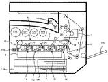
図1は、本プリンタの構成を示す概略構成図である。
このプリンタは、図1に示されるように、イエロー(Y)、シアン(C)、マゼンタ(M)、黒(K)の各色の画像を形成するための電子写真プロセスを実行する4つのプロセスユニット1Y,1C,1M,1Kを備えている。以下、各符号の添字Y、C、M、Kは、それぞれイエロー、シアン、マゼンタ、黒用の部材であることを示す。Y、C、M、Kの色順は、図1に示される順に限られるものでなく、他の並び順であっても構わない。
Hereinafter, an electrophotographic printer will be described as an example of an embodiment of an image forming apparatus to which the present invention is applied.
First, the basic configuration of the printer will be described.
FIG. 1 is a schematic configuration diagram showing the configuration of the printer.
As shown in FIG. 1, this printer has four process units that execute an electrophotographic process for forming images of each color of yellow (Y), cyan (C), magenta (M), and black (K). 1Y, 1C, 1M, 1K. Hereinafter, the subscripts Y, C, M, and K of the respective symbols indicate members for yellow, cyan, magenta, and black, respectively. The color order of Y, C, M, and K is not limited to the order shown in FIG. 1, and may be another order of arrangement.
図2は、本プリンタにおける4つのプロセスユニット1Y,1C,1M,1Kと、転写ユニット8とを示す拡大構成図である。
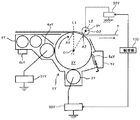
図3は、本プリンタにおけるY用のプロセスユニットの構成を示す構成図である。
プロセスユニット1Y,1C,1M,1Kは、潜像担持体としてのドラム状の感光体2Y,2C,2M,2Kを有している。図中時計回り方向に回転駆動する感光体2Y,2C,2M,2Kの表面には、後述するように、Y、C、M、Kの色の各トナー像が形成される。
FIG. 2 is an enlarged configuration diagram showing four
FIG. 3 is a configuration diagram showing a configuration of a process unit for Y in the printer.
The
プロセスユニット1Y,1C,1M,1Kの上方には、転写ユニット8が配設されている。転写ユニット8には、被転写材としての無端状の中間転写ベルト7が設けられ、中間転写ベルト7は図中反時計回り方向に無端移動する。中間転写ベルト7の全周のうち、外周面が下方に向けている領域には、その外周面に感光体2Y,2C,2M,2Kが当接してY、C、M、K用の一次転写ニップを形成している。中間転写ベルト7の内周面側には、Y、C、M、K用の一次転写ローラ9Y,9C,9M,9Kが配設されており、感光体2Y,2C,2M,2Kとの間に中間転写ベルト7を挟み込んでいる。この挟み込みにより、Y、C、M、K用の一次転写ニップが形成される。各一次転写ローラ9Y,9C,9M,9Kには、転写電源52Y,52C,52M,52Kから所定の一次転写電圧が印加される。
A
一般に、一次転写ローラ9Y,9C,9M,9K等の転写ローラに転写電圧を印加して転写を行うローラ転写方式では、感光体2Y,2C,2M,2Kの位置に対して転写ローラをどのように配置するかが重要な設計パラメータとなっている。この配置の違いによって、ローラ転写方式には、転写ローラを感光体に正対する位置に配置する直接印加転写方式と、転写ローラを感光体に正対する位置よりも感光体表面移動方向(中間転写ベルト7の表面移動方向)の下流側にずらして配置(オフセット)する間接印加転写方式がある。
In general, in a roller transfer system in which transfer is performed by applying a transfer voltage to the transfer rollers such as the
図3を参照して、本実施形態における中間転写ベルト7を有するプリンタの一次転写ローラ9Yを例に挙げて詳しく説明する。
間接印加転写方式の場合、感光体2Yの表面移動方向に直交する仮想面(図3の紙面)において、感光体2Yの回転中心(表面曲率中心)O1と一次転写ローラ9Yの回転中心O2とを結ぶ仮想線L2が通る感光体2Yの表面上の地点A2が、一次転写ローラ9Yを設置しない状態で中間転写ベルト7に最近接する感光体2Yの表面上の地点A1よりも感光体表面移動方向下流側に位置するように、一次転写ローラ9Yが設置される。
一方、直接印加転写方式の場合、感光体2Yの表面移動方向に直交する仮想面(図3の紙面)において、感光体2Yの回転中心(表面曲率中心)O1と一次転写ローラ9Yの回転中心O2とを結ぶ仮想線が図3中符号L1となるように、一次転写ローラ9Yが設置される。すなわち、直接印加転写方式では、感光体2Yの回転中心(表面曲率中心)O1と一次転写ローラ9Yの回転中心O2とを結ぶ仮想線L1が通る感光体2Yの表面上の地点A1は、一次転写ローラ9Yを設置しない状態で中間転写ベルト7に最近接する感光体2Yの表面上の地点A1と略同一地点となる。
With reference to FIG. 3, the
In the case of the indirect application transfer method, the rotation center (surface curvature center) O1 of the
On the other hand, in the case of the direct application transfer method, the rotation center (surface curvature center) O1 of the
本実施形態においては、図3に示すように、一次転写ローラ9Y,9C,9M,9Kについて間接印加転写方式を採用している。間接印加転写方式では、一次転写に必要な一次転写ニップを、一次転写ローラ9Y,9C,9M,9Kにより中間転写ベルト7を感光体2Y,2C,2M,2Kの表面に巻き付けるように押し当てて形成するため、一次転写ローラ9Y,9C,9M,9Kそれ自体がゴム等の弾性層を有するローラである必要がない。そのため、耐久性や加工精度等に優れた金属ローラで一次転写ローラ9Y,9C,9M,9Kを構成できるというメリットがある。加えて、間接印加転写方式の場合、比較的低い電気抵抗値をもつ中間転写ベルト7を用いることができることから、中間転写ベルト7を低コストで製造可能であり、低コスト化の観点でもメリットがある。
In this embodiment, as shown in FIG. 3, an indirect application transfer method is adopted for the
中間転写ベルト7は、複数のローラに張架されながら、少なくとも1つのローラの回転駆動によって図中反時計回り方向に無端移動する。転写ユニット8は、中間転写ベルト7や一次転写ローラ9Y,9C,9M,9Kのほか、ブラシローラやクリーニングブレードなどから構成されるクリーニング装置10を有している。また、二次転写バックアップローラ11、二次転写ローラ12なども有している。
The
一次転写ローラ9Y,9C,9M,9Kには、転写電源によってトナーの帯電極性とは逆極性の一次転写電圧が印加される。これにより、Y、C、M、K用の一次転写ニップに一次転写バイアスが印加され、感光体2Y,2C,2M,2K上のY、C、M、Kトナー像を感光体側から中間転写ベルト側に静電移動させる一次転写電界が形成される。中間転写ベルト7は、無端移動に伴って、Y、C、M、K用の一次転写ニップを順に通過する。この過程で、感光体2Y,2C,2M,2K上のY、C、M、Kトナー像が順に重ね合わせて中間転写ベルト7の外周面上に一次転写される。これにより、中間転写ベルト7の外周面には、4色重ね合わせトナー像が形成される。
A primary transfer voltage having a polarity opposite to the charging polarity of the toner is applied to the
二次転写ローラ12は、中間転写ベルト7の図中右側方に配設され、中間転写ベルト7の外周面に当接して二次転写ニップを形成する。中間転写ベルト7の内周面側に配設された二次転写バックアップローラ11は、二次転写ローラ12との間に中間転写ベルト7を挟み込んでいる。これにより、二次転写ニップが形成される。
The
プロセスユニット1Yに設けられたドラム状の感光体2Yの周囲には、図3に示すように、帯電ローラ3Yを具備する帯電手段としての帯電装置、現像手段としての現像装置4Y、クリーニング手段としてのクリーニング装置5Yなどが配設されている。帯電ローラ3Yは、感光体2Yの表面に接触しながら回転するようになっている。本プリンタでは、かかる帯電ローラ3Yに対してAC成分を含まないDC成分のみの直流電圧を帯電電源50Yから印加する接触DC帯電方式を採用している。なお、帯電装置には、接触AC帯電ローラ方式や、非接触帯電方式などの他の方式を採用することもできる。
As shown in FIG. 3, a charging device as a charging unit having a charging
現像装置4Y内には、Yトナーと磁性キャリアとを含有する二成分現像剤が収容されている。現像装置4Yは、感光体2Yに対向した現像剤担持体である現像ローラ4aY、現像ローラ4aYに現像電圧を印加する現像電源51Y、現像剤を搬送・撹拌するスクリュー、トナー濃度センサ4bY等から構成される。現像ローラ4aYは、現像電源51Yから現像電圧が印加される中空で回転自在なスリーブと、これに連れ回らないように内包されるマグネットローラとから構成されている。
A two-component developer containing Y toner and a magnetic carrier is accommodated in the developing
クリーニング装置5Yは、クリーニングブレード5aYを感光体2Yの表面に当接させて転写残トナー等の不要トナーをクリーニングするブレード方式のものである。
The cleaning device 5Y is of a blade type that cleans unnecessary toner such as transfer residual toner by bringing the cleaning blade 5aY into contact with the surface of the
プロセスユニット1Yは、感光体2Yと、その周囲に配設される帯電ローラ3Y、現像装置4Y、クリーニング装置5Yとが1つのユニットとして共通の支持体に支持した状態で、プリンタ本体に対して一体的に着脱される。一体的に着脱することにより、個別に着脱する場合に比べて、メンテナンス性を向上させることができる。Y用のプロセスユニット1Yについて説明したが、他色用のプロセスユニット1C,1M,1Kは、トナーとして、Cトナー、Mトナー、Kトナーを用いる点を除いて、Y用のプロセスユニットとほぼ同様の構成になっている。
The
図1において、プロセスユニット1Y,1C,1M,1Kの下方には、潜像形成手段としての光書込ユニット6が配設されている。光書込ユニット6は、光源、ポリゴンミラー、f−θレンズ、反射ミラー等を備え、入力される印刷ジョブの画像情報に基づいて各色の感光体2Y,2C,2M,2Kの表面に対してレーザー光Lの光走査を行う。この光走査により、感光体2Y,2C,2M,2K上に、Y、C、M、Kの静電潜像が形成される。
In FIG. 1, an
転写ユニット8の二次転写ローラ12の上方には、定着手段としての定着ユニット13が配設されている。定着ユニット13は、互いに回転しながら当接して定着ニップを形成する定着ローラと加圧ローラとを備えている。定着ローラは、ハロゲンヒータを内蔵し、定着ローラ表面が所定の温度となるように、電源からヒータへ電力が供給され、加圧ローラとの間に定着ニップを形成している。
Above the
プリンタ本体の下部には、出力画像が記録される記録材としての記録シートSを複数枚重ねて収容する給紙カセット14a、14b、給紙ローラ、レジストローラ対15などが配設されている。また、プリンタ本体の側面には、側面から手差しで給紙を行うための手差しトレイ14cが備えられている。また、転写ユニット8や定着ユニット13の図中右側には、両面印刷時に記録シートSを再び二次転写ニップへ搬送するための両面ユニット16が設けられている。
In the lower part of the printer main body, paper feed cassettes 14a and 14b for storing a plurality of recording sheets S as recording materials on which an output image is recorded, a paper feed roller, a resist
プリンタ本体の上部には、プロセスユニット1Y,1C,1M,1Kの各現像装置へ補給するためのトナーを収容するトナー容器17Y、17C、17M、17Kが設置されている。また、プリンタ本体には、廃トナーボトル、電源ユニットなども設けられている。
In the upper part of the printer main body,
本実施形態におけるプリンタの画像形成動作は、次の通りである。
本プリンタに印刷ジョブが入力されると、まず、各色のプロセスユニット1Y,1C,1M,1Kにおいて、電子写真プロセスが開始される。Y用のプロセスユニット1Yを例にすると、帯電電源50Yから出力される帯電電圧が帯電ローラ3Yに印加され、これによって帯電ローラ3Yと感光体2Yとの間に帯電バイアスが印加され、感光体2Yの表面がマイナス極性に一様帯電される。そして、一様帯電後の感光体2Yの表面には、光書込ユニット6によって、本印刷ジョブに係る画像情報に基づいてレーザー光Lの走査がなされる。これにより、光が照射された感光体2Yの表面上の部分(潜像部分)の帯電電位の大きさが小さくなり、静電潜像が書き込まれることになる。このような静電潜像を担持した感光体2Yの表面は、感光体2Yの回転に伴って現像装置4Yとの対向位置に到達する。感光体2Yと対向配置される現像ローラ4aYには現像電圧が印加されており、これにより感光体2Yと現像ローラ4aYとの間に現像バイアスが印加される。その結果、マイナス極性に帯電したYトナーを感光体2Yの表面上の潜像部分へ移動させる現像電界が形成され、感光体2Yの表面上の静電潜像が現像され、Yトナー像が形成される。現像装置4Y内には、トナー濃度センサ4bYの出力に応じて、トナー容器17Yから適量のYトナーが補給される。
The image forming operation of the printer in this embodiment is as follows.
When a print job is input to this printer, first, an electrophotographic process is started in each
同様の動作がプロセスユニット1C,1M,1Kにおいても所定のタイミングで行われる。これにより、感光体2Y,2C,2M,2Kの表面に、Y、C、M、Kの各色トナー像が形成される。これらY、C、M、Kの各色トナー像は、既に述べたように、Y、C、M、K用の一次転写ニップで中間転写ベルト7の外周面に順に重ね合わせて一次転写され、4色重ね合わせトナー像になる。
Similar operations are performed at predetermined timings in the
また、印刷ジョブが開始された後、所定のタイミングで、記録シートSが給紙カセット14a,14bもしくは手差しトレイ14cから送り出されて、レジストローラ対15に到達したところで一旦停止する。そして、所定のタイミングに合わせてレジストローラ対15が回転し、記録シートSが二次転写ニップへ向けて送り出される。中間転写ベルト7上に形成された4色重ね合わせトナー像は、二次転写ニップで記録シートSに二次転写される。この二次転写は、二次転写電源によって二次転写ローラ12にトナーと逆極性(プラス極性)の電圧が印加されることで行われる。
In addition, after the print job is started, the recording sheet S is sent out from the paper feed cassettes 14 a and 14 b or the manual feed tray 14 c at a predetermined timing, and is temporarily stopped when it reaches the
記録シートSは、二次転写ニップを通過した後に定着ユニット13に向けて搬送されて定着ニップに挟み込まれる。記録シートS上のトナー像は、定着ニップにおいて定着ローラの熱や圧力により加熱加圧定着される。トナー像が定着された記録シートSは、片面印刷の場合には、各搬送ローラによって機外へ排出される。一方、両面印刷の場合、記録シートSは、各搬送ローラによって両面ユニット16へ搬送されて反転され、先に画像が形成された面とは反対側の面に、上述したように画像が形成された後に機外へ排出される。
After passing through the secondary transfer nip, the recording sheet S is conveyed toward the fixing
次に、残像の発生パターンについて説明する。
本実施形態のプリンタにおいて、残像の発生パターンは2種類ある。
1つ目の残像発生パターンは、図4(a)及び(b)に示すように、感光体2Y,2C,2M,2K上に形成されたトナー像の転写残トナーがそのまま感光体2Y,2C,2M,2K上に残留し、これが次の周回時のトナー像とともに中間転写ベルト7へ一次転写されて残像となるパターンである。
2つ目の残像発生パターンは、図5(a)及び(b)に示すように、例えば、中間転写ベルト上に先に一次転写されたYトナー像が、中間転写ベルト無端移動方向下流側に位置するKの一次転写ニップを通過する時に、Kの感光体2Kの表面に当該Yトナー像に倣った電位差が生じてKトナーの残像が生じるパターンである。
Next, an afterimage generation pattern will be described.
In the printer of this embodiment, there are two types of afterimage generation patterns.
As shown in FIGS. 4A and 4B, the first afterimage generation pattern is such that the transfer residual toners of the toner images formed on the
As shown in FIGS. 5A and 5B, the second afterimage generation pattern is, for example, that the Y toner image that has been first transferred onto the intermediate transfer belt is downstream in the endless movement direction of the intermediate transfer belt. This is a pattern in which, after passing through the K primary transfer nip, a potential difference following the Y toner image is generated on the surface of the
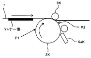
図6は、上述した1つ目の残像発生パターンの発生メカニズムを説明するためのK用の感光体2Kを示す説明図である。
図7(a)は、転写前における感光体2Kの表面上の電位分布を概略的に示すグラフである。
図7(b)は、転写後における感光体2Kの表面上の電位分布を概略的に示すグラフである。
FIG. 6 is an explanatory diagram showing a
FIG. 7A is a graph schematically showing a potential distribution on the surface of the
FIG. 7B is a graph schematically showing a potential distribution on the surface of the
図6に示すように、Kトナーが付着する潜像部分とKトナーが付着しない非潜像部分との境界部分を有する画像パターンを一次転写する場合、現像後かつ一次転写前の地点P1において測定される感光体の表面電位は、図7(a)に示すようなものとなる。帯電ローラ3Yにより約−900Vに一様帯電された感光体2Kの表面電位は、光書込ユニット6によるレーザー光Lが照射されることで、その照射領域(潜像部分)の電位は約−70V程度まで落とされる。その潜像部分には、現像装置4Kの現像処理によりマイナス極性のKトナーが付着する。その結果、現像後かつ一次転写前の地点P1において測定される感光体の表面電位は、図7(a)に示すように、非潜像部分では約−900Vであり、トナーが付着した後の潜像部分では約−70Vとなる。
As shown in FIG. 6, when primary transfer is performed on an image pattern having a boundary portion between a latent image portion to which K toner adheres and a non-latent image portion to which K toner does not adhere, measurement is performed at a point P1 after development and before primary transfer. The surface potential of the photoconductor is as shown in FIG. The surface potential of the
このようなKトナー像が一次転写ニップを通過する際、一次転写バイアスを受けて中間転写ベルト7へ一次転写されると、一次転写後かつクリーニング前の地点P2において測定される感光体の表面電位は、図7(b)に示すようなものとなる。一次転写ニップを通過するとき、一次転写バイアスの作用により、プラス極性の転写電圧が印加された一次転写ローラ9Kから中間転写ベルト7を介して感光体2Kへ一次転写電流が流れ込む。この一次転写電流の流れ込みにより、転写後の感光体2Kの表面上における非潜像部分の電位はプラス極性側へシフトし、図7(b)に示すように、約−550V程度まで落ち込む。なお、転写後の感光体2Kの表面上における潜像部分の電位はすでに十分に落ち込んでいるため、それ以上はプラス極性側へシフトすることができず、図7(b)に示すように、約−70V程度のままである。
When such a K toner image passes through the primary transfer nip and receives the primary transfer bias and is primarily transferred to the
ここで、潜像部分と非潜像部分との間における転写後の感光体表面電位の電位差(ムラの大きさ)が大きいほど、非潜像部分に隣接する潜像部分の境界部(エッジ部)では、電界の回り込みによって局所的に強い電界が形成される。そのため、このようなエッジ部では、一次転写後に感光体2K上に残留した転写残トナー(不要トナー)を感光体2Kの表面上に静電的に引きつけて拘束する力が強い。このように強い力で感光体2Kの表面上に拘束された転写残トナーは、クリーニング装置5Kのクリーニングブレード5aKが当接しているクリーニング箇所をすり抜けやすい。クリーニング箇所をすり抜けた転写残トナーは、次の帯電処理、潜像形成処理、現像処理を経てもなお、そのまま感光体2Kの表面上に保持され、次の一次転写ニップを通過する際に、一次転写バイアスの作用によって中間転写ベルト7へ一次転写される。これにより、図4(b)に示すように、Kトナーによる残像が発生する。
Here, the larger the potential difference (unevenness magnitude) of the photoreceptor surface potential after transfer between the latent image portion and the non-latent image portion, the larger the boundary portion (edge portion) of the latent image portion adjacent to the non-latent image portion. ), A locally strong electric field is formed by the wraparound of the electric field. Therefore, such an edge portion has a strong force for electrostatically attracting and restraining the transfer residual toner (unnecessary toner) remaining on the
また、このようなエッジ部に局所的な強い電界が形成されると、そのエッジ部の電位(約−70V)が次の帯電処理を受けても約−900Vまで帯電されない場合がある。このような場合、そのエッジ部は、次の潜像形成処理においてレーザー光が照射されない非潜像部分であっても、次の現像処理においてトナーが付着してしまう。その結果、このエッジ部に付着したトナーが次の一次転写ニップを通過する際に一次転写バイアスの作用によって中間転写ベルト7へ一次転写され、図4(b)に示すように、Kトナーによる残像が発生する。
Further, when a local strong electric field is formed at such an edge portion, the potential at the edge portion (about −70 V) may not be charged to about −900 V even when the next charging process is performed. In such a case, even if the edge portion is a non-latent image portion that is not irradiated with laser light in the next latent image forming process, toner adheres in the next developing process. As a result, when the toner adhering to the edge portion passes through the next primary transfer nip, it is primarily transferred to the
図8は、上述した2つ目の残像発生パターンの発生メカニズムを説明するためのK用の感光体2Kを示す説明図である。
図9(a)は、転写前における感光体2Kの表面上の電位分布を概略的に示すグラフである。
図9(b)は、転写後における感光体2Kの表面上の電位分布を概略的に示すグラフである。
FIG. 8 is an explanatory diagram showing a
FIG. 9A is a graph schematically showing a potential distribution on the surface of the
FIG. 9B is a graph schematically showing a potential distribution on the surface of the
図8に示すように、Kトナーが付着しない非潜像部分が一次転写ニップを通過するとき、K用の感光体2Kよりも中間転写ベルト7の表面移動方向上流側に位置する他の感光体(ここではY用の感光体2Y)から一次転写された中間転写ベルト7上のYトナー像が当該一次転写ニップを通過する場合がある。この場合、現像後かつ一次転写前の地点P1において測定されるK用の感光体2Kの表面電位は、非潜像部分であるため、図9(a)に示すように、約−900Vで一様である。このような非潜像部分が一次転写ニップを通過する際、一次転写バイアスの作用により、プラス極性の転写電圧が印加された一次転写ローラ9Kから中間転写ベルト7を介して感光体2Kへ一次転写電流が流れ込む。この一次転写電流の流れ込みにより、転写後の感光体2Kの表面電位はプラス極性側へシフトし、落ち込む。
As shown in FIG. 8, when a non-latent image portion to which K toner does not adhere passes through the primary transfer nip, another photoconductor positioned on the upstream side in the surface movement direction of the
このとき、K用の一次転写ニップを通過する中間転写ベルト7上に、Yトナー像が付着しているYトナー像部分とYトナー像が付着していない非Yトナー像部分とが存在する場合、感光体2Kへ流れ込む一次転写電流の量が、Yトナー像部分と非Yトナー像部分とで異なるものとなる。具体的には、Yトナー像部分を通る一次転写電流は、その一部がYトナー像を構成するYトナーのチャージアップに使用され、その分だけ、K用の感光体2Kへ流れ込む一次転写電流の量が、非Yトナー像部分を通る一次転写電流よりも少ないものとなる。その結果、K用の感光体2Kの表面電位は、図9(b)に示すように、中間転写ベルト7上のYトナー像と対向する感光体2KのYトナー像対向部分についての表面電位(約−400V)は、中間転写ベルト7上のYトナー像と対向しない感光体2Kの非Yトナー像対向部分についての表面電位(約−450V)よりも、電位の落ち込み量が少なくなる。
At this time, when the Y toner image portion to which the Y toner image is attached and the non-Y toner image portion to which the Y toner image is not attached exist on the
上述したように、転写後の感光体表面上における電位変化が大きい箇所(エッジ部)では、電界の回り込みによって局所的に強い電界が形成される。そのため、K用の感光体2Kの表面上におけるYトナー像対向部分と非Yトナー像対向部分との間の境界部分(エッジ部)でも、電界の回り込みによって局所的に強い電界が形成され得る。そして、このようなエッジ部では、上述したとおり、そのエッジ部の電位が次の帯電処理を受けても約−900Vまで帯電されない場合があり、このような場合、そのエッジ部に次の現像処理においてトナーが付着し、次の一次転写ニップを通過する際に中間転写ベルト7へ一次転写されて、図5(b)に示すように、Kトナーによる残像が発生し得る。
As described above, a strong electric field is locally formed by the wraparound of the electric field at a portion (edge portion) where the potential change on the surface of the photoreceptor after transfer is large. Therefore, a strong electric field can be locally formed by the wraparound of the electric field at the boundary portion (edge portion) between the Y toner image facing portion and the non-Y toner image facing portion on the surface of the
特に、本実施形態においては、間接印加転写方式を採用しているため、上述したいずれの残像発生パターンで発生する残像も、直接印加転写方式より発生しやすいものとなっている。詳しく説明すると、直接印加転写方式では、通常、間接印加転写方式よりも感光体へ流れ込む転写電流量を多くすることができる。そのため、直接印加転写方式であれば、1つ目の発生パターンの場合、感光体の表面が一次転写ニップを通過することにより、非潜像部分の電位が十分に落とされ、非潜像部分と潜像部分との電位差(電位ムラ)が小さく又はほぼ無くなり、そのエッジ部に局所的な強い電界が生じることが少なく、残像が生じにくい。 In particular, in the present embodiment, since the indirect application transfer method is adopted, the afterimage generated in any of the above-described afterimage generation patterns is more likely to occur than in the direct application transfer method. More specifically, in the direct application transfer method, the amount of transfer current flowing into the photoconductor can usually be increased as compared with the indirect application transfer method. Therefore, in the case of the direct application transfer method, in the case of the first generation pattern, the surface of the photoreceptor passes through the primary transfer nip, so that the potential of the non-latent image portion is sufficiently lowered, and the non-latent image portion The potential difference (potential unevenness) with the latent image portion is small or almost eliminated, a local strong electric field is hardly generated at the edge portion, and an afterimage hardly occurs.
これに対し、間接印加転写方式であると、直接印加転写方式よりも転写電流量が少ないため、1つ目の発生パターンの場合、感光体の表面が一次転写ニップを通過するときに、非潜像部分の電位が十分に落ちない。そのため、非潜像部分と潜像部分との電位差(電位ムラ)が大きく、そのエッジ部に局所的な強い電界が生じて、残像が生じやすい。 In contrast, in the indirect application transfer method, the amount of transfer current is smaller than in the direct application transfer method. Therefore, in the case of the first generated pattern, when the surface of the photoconductor passes through the primary transfer nip, it is non-latent. The potential of the image part does not drop sufficiently. Therefore, the potential difference (potential unevenness) between the non-latent image portion and the latent image portion is large, and a strong local electric field is generated at the edge portion, and an afterimage is likely to occur.
また、転写電流量が多い直接印加転写方式であれば、2つ目の発生パターンの場合、一次転写ニップを、中間転写ベルト表面移動方向上流側の感光体から一次転写された中間転写ベルト7上の他色トナー像が通過するとき、他色トナー像を流れる転写電流のうちトナーのチャージアップ分の占める割合が少なくなる。そのため、一次転写ニップで中間転写ベルト7上の他色トナー像と対向する他色トナー像対向部分(図9におけるYトナー像対向部分)にも、他色トナー像と対向しない非他色トナー像対向部分(図9における非Yトナー像対向部分)と同程度の転写電流が流れる。その結果、他色トナー像対向部分と非他色トナー像対向部分との電位差(電位ムラ)が小さく又はほぼ無くなり、そのエッジ部に局所的な強い電界が生じることが少なく、残像が生じにくい。
Further, in the case of the direct application transfer method with a large transfer current amount, in the case of the second generation pattern, the primary transfer nip is transferred onto the
これに対し、間接印加転写方式であると、直接印加転写方式よりも転写電流量が少ないため、2つ目の発生パターンの場合、中間転写ベルト上の他色トナー像を流れる転写電流のうちトナーのチャージアップ分の占める割合が多くなる。そのため、他色トナー像対向部分(図9におけるYトナー像対向部分)を流れる転写電流量が、非他色トナー像対向部分(図9における非Yトナー像対向部分)よりも有意に少なくなる。その結果、他色トナー像対向部分と非他色トナー像対向部分との電位差(電位ムラ)が大きく、そのエッジ部に局所的な強い電界が生じて、残像が生じやすい。 On the other hand, in the indirect application transfer method, the transfer current amount is smaller than in the direct application transfer method. Therefore, in the case of the second generated pattern, the toner out of the transfer current flowing through the other color toner image on the intermediate transfer belt. The percentage of charge up will increase. Therefore, the amount of transfer current flowing through the other color toner image facing portion (the Y toner image facing portion in FIG. 9) is significantly smaller than the non-other color toner image facing portion (the non-Y toner image facing portion in FIG. 9). As a result, the potential difference (potential unevenness) between the other color toner image facing portion and the non-other color toner image facing portion is large, and a strong local electric field is generated at the edge portion, and an afterimage tends to occur.
上述した残像は、形成される画像(1つ目の残像発生パターンにおいては自らの感光体上に形成されるトナー像である。2つ目の残像発生パターンにおいては中間転写ベルト表面移動方向上流側の感光体から中間転写ベルト7へ一次転写されたトナー像である。)が細線画像を含むような画像パターンであるという条件下(残像発生条件下)において発生しやすい。これは、細線画像では、転写後における感光体表面上の電位変化が生じるエッジ部同士が近接するためである。
The above-mentioned afterimage is an image to be formed (in the first afterimage generation pattern, a toner image formed on its own photoconductor. In the second afterimage generation pattern, the intermediate transfer belt surface movement direction upstream side. The toner image is primarily transferred from the photoconductor to the
また、画像形成装置の設置環境の温度が低温であるという条件下(残像発生条件下)においては、クリーニング性能が不十分となりやすく、クリーニング箇所のトナーのすり抜けが発生しやすくなる。特に、感光体の温度が低温であるという条件(残像発生条件下)では、クリーニングブレードも低温であり、クリーニング性能が不十分となってクリーニング箇所のトナーのすり抜けが発生しやすくなる。そのため、このような残像発生条件下では、特に上述した1つ目の発生メカニズムによる残像が発生しやすい。 Further, under the condition that the temperature of the installation environment of the image forming apparatus is low (afterimage generation condition), the cleaning performance tends to be insufficient, and the toner passing through the cleaning portion is likely to occur. In particular, under the condition that the temperature of the photoconductor is low (under the afterimage generation condition), the cleaning blade is also low in temperature, and the cleaning performance becomes insufficient, so that toner passing through the cleaning portion is likely to occur. Therefore, under such afterimage generation conditions, an afterimage due to the first generation mechanism described above is likely to occur.
また、クリーニング装置5Y,5C,5M,5Kのクリーニングブレード5aが経時使用により劣化してくると、クリーニング性能が不十分となり、クリーニング箇所のトナーのすり抜けが発生しやすくなる。したがって、クリーニングブレード5aの使用量(感光体表面に対するクリーニングブレードの相対移動距離など)が規定量を超えるという条件下(残像発生条件下)においては、特に上述した1つ目の発生メカニズムによる残像が発生しやすい。 Further, when the cleaning blade 5a of the cleaning devices 5Y, 5C, 5M, and 5K deteriorates due to use over time, the cleaning performance becomes insufficient, and the toner at the cleaning portion is likely to slip through. Therefore, under the condition that the amount of cleaning blade 5a used (such as the relative movement distance of the cleaning blade with respect to the surface of the photosensitive member) exceeds a specified amount (under the afterimage generation condition), the afterimage due to the first generation mechanism described above is particularly generated. Likely to happen.
また、2色以上のトナー像が互いに重なり合って中間転写ベルト7上に形成されているトナー像が一次転写ニップを通過するような画像パターンであるという条件下(残像発生条件下)においては、残像が発生しやすい。これは、中間転写ベルト7上における2色以上の重ねトナー像が一次転写ニップを通過する場合、その一次転写ニップ中で当該トナー像部分を通る一次転写電流のうち、当該トナーのチャージアップ分の占める割合がより多くなるためである。したがって、このような画像パターンが形成されるという残像発生条件下においては、特に上述した2つ目の発生メカニズムによる残像が発生しやすい。
Further, an afterimage is obtained under a condition that the toner image formed on the
そして、このように残像が発生しやすい残像発生条件が満たされる状況下では、転写後における感光体上の表面電位ムラの大きさが大きくなると、上述した1つ目の発生メカニズムあるいは上述した2つ目の発生メカニズムによって、残像が発生してしまう。 Then, under such a condition that the afterimage generation condition in which an afterimage is likely to be generated is satisfied, if the size of the surface potential unevenness on the photoconductor after transfer increases, the first generation mechanism described above or the above two An afterimage is generated by the generation mechanism of the eyes.
次に、本実施形態における残像抑制処理について説明する。
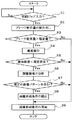
図10は、本実施形態における残像抑制処理の流れを示すフローチャートである。
本実施形態においては、制御部100は、印刷ジョブが入力されるタイミング等の所定の実行タイミングが到来するたびに、残像抑制処理を開始する。制御部100は、印刷ジョブが入力されると(S1)、まず、所定の記憶部に記憶されているブレード使用量情報を読み出し(S2)、そのブレード使用量情報が示すブレード使用量が規定量を超えているか否かを判断する(S3)。本実施形態のブレード使用量情報は、現在使用しているクリーニングブレード5aの使用開始時期からの感光体走行距離を示す情報、すなわち、クリーニング装置5Y,5C,5M,5Kのクリーニングブレード5aと感光体2Y,2C,2M,2Kの表面との相対移動距離を示す情報である。ただし、このようなブレード使用量情報に限らず、クリーニング装置5Y,5C,5M,5Kの使用量を示す使用量情報であれば、他の情報であってもよい。
Next, the afterimage suppression processing in this embodiment will be described.
FIG. 10 is a flowchart showing the flow of afterimage suppression processing in the present embodiment.
In the present embodiment, the
上述したとおり、ブレード使用量が規定量を超えている場合、クリーニング箇所のトナーのすり抜けが発生しやすくなり、転写後における感光体上の表面電位ムラの大きさが大きいと、特に上述した1つ目の発生メカニズムによる残像が発生しやすい。逆に、ブレード使用量が規定量を超えていなければ、転写後における感光体上の表面電位ムラの大きさが大きくても、残像が発生しにくい。そのため、本実施形態では、ブレード使用量が規定量を超えていない場合には(S3のNo)、画像形成条件を補正することなく、通常の画像形成条件で画像形成動作を開始する(S9)。なお、本実施形態における規定量は、クリーニングブレード5aが寿命を迎える予め決められた寿命使用量の半分に設定されているが、適宜調整可能である。 As described above, when the amount of blade used exceeds the specified amount, toner passing through the cleaning portion easily occurs, and the surface potential unevenness on the photosensitive member after transfer is large. An afterimage is likely to occur due to the generation mechanism of the eyes. Conversely, if the amount of blade used does not exceed the specified amount, afterimages are unlikely to occur even if the surface potential unevenness on the photoreceptor after transfer is large. Therefore, in this embodiment, when the blade usage amount does not exceed the prescribed amount (No in S3), the image forming operation is started under the normal image forming conditions without correcting the image forming conditions (S9). . Note that the specified amount in the present embodiment is set to half of a predetermined lifetime usage amount at which the cleaning blade 5a reaches the lifetime, but can be adjusted as appropriate.
また、ブレード使用量が規定量を超えている場合でも(S3のYes)、画像形成装置の設置環境の温度(特に感光体の温度)が高温であれば、クリーニング性能が十分に維持され、クリーニング箇所のトナーのすり抜けが発生しにくく、転写後における感光体上の表面電位ムラの大きさが大きくても、残像が発生しにくい。そのため、本実施形態では、ブレード使用量が規定量を超えていない場合でも(S3のYes)、温度センサで検知した検知温度が規定温度を超えていない場合には(S4,S5のNo)、画像形成条件を補正することなく、通常の画像形成条件で画像形成動作を開始する(S9)。 Even when the blade usage exceeds the specified amount (Yes in S3), if the temperature of the installation environment of the image forming apparatus (especially the temperature of the photoreceptor) is high, the cleaning performance is sufficiently maintained and the cleaning is performed. It is difficult for toner to pass through the portion, and even if the surface potential unevenness on the photoreceptor after transfer is large, an afterimage is difficult to occur. Therefore, in this embodiment, even when the blade usage amount does not exceed the specified amount (Yes in S3), when the detected temperature detected by the temperature sensor does not exceed the specified temperature (No in S4 and S5), The image forming operation is started under normal image forming conditions without correcting the image forming conditions (S9).
なお、本実施形態では、各プロセスユニット1Y,1C,1M,1Kに温度センサが設置され、感光体2Y,2C,2M,2Kの周囲の温度を検知する構成となっているが、他の箇所の温度を検知してもよい。また、本実施形態における規定温度は、15℃に設定されているが、適宜調整可能である。
In the present embodiment, a temperature sensor is installed in each
図11は、横軸にブレード使用量をとり、縦軸に検知温度をとったグラフにおいて、通常の画像形成条件で画像形成動作を実施する領域と、補正後の画像形成条件で画像形成動作を実施する領域とを図示したものである。 FIG. 11 is a graph in which the amount of blade used is taken on the horizontal axis and the detected temperature is taken on the vertical axis, and the area where the image forming operation is performed under normal image forming conditions and the image forming operation under the corrected image forming conditions. The area to be implemented is illustrated.
また、ブレード使用量が規定量を超えていて(S3のYes)、かつ、検知温度も規定温度を超えている場合(S5のYes)でも、形成する画像が、残像を生じやすい規定の画像パターンを含まない場合には、転写後における感光体上の表面電位ムラの大きさが大きくても、残像が発生しにくい。残像を生じやすい規定の画像パターンとは、具体的には、例えば、上述したように、細線画像を含むような画像パターンや、2色以上のトナー像が互いに重なり合って中間転写ベルト7上に形成されているトナー像が一次転写ニップを通過するような画像パターンなどである。なお、ここでいう細線画像とは、図12に示すように、副走査方向A(中間転写ベルト表面移動方向に対応する方向)における画像部分の長さaが規定長さ(例えば、600dpiの画像であれば12dot分)以下である画像部分を含むものである。
Further, even when the amount of blade used exceeds the prescribed amount (Yes in S3) and the detected temperature exceeds the prescribed temperature (Yes in S5), the prescribed image pattern in which the image to be formed tends to cause an afterimage. In the case where it does not contain, afterimage is hardly generated even if the surface potential unevenness on the photoreceptor after transfer is large. Specifically, for example, as described above, an image pattern including a fine line image or two or more color toner images are formed on the
そのため、本実施形態では、ブレード使用量が規定量を超えていて(S3のYes)、かつ、検知温度も規定温度を超えている場合(S5のYes)でも、形成する画像が規定の画像パターンを含まない場合には(S6,S7のNo)、画像形成条件を補正することなく、通常の画像形成条件で画像形成動作を開始する(S9)。形成する画像が規定の画像パターンを含むか否かの判断では、例えば、入力された印刷ジョブに係る画像情報を制御部100が取得し、制御部100が当該画像情報を分析して規定の画像パターンを含むかどうかの判定を行う。
Therefore, in this embodiment, even when the amount of blade used exceeds the specified amount (Yes in S3) and the detected temperature exceeds the specified temperature (Yes in S5), the image to be formed is the specified image pattern. Is not included (No in S6 and S7), the image forming operation is started under normal image forming conditions without correcting the image forming conditions (S9). In determining whether the image to be formed includes a prescribed image pattern, for example, the
一方、本実施形態では、ブレード使用量が規定量を超えていて(S3のYes)、かつ、検知温度も規定温度を超えていて(S5のYes)、更に、形成する画像が規定の画像パターンを含む場合(S7のYes)、制御部100は、残像発生条件を満たすと判断して、残像が発生しにくくなるように、画像形成条件を補正する(S8)。具体的には、制御部100は、このような残像発生条件を満たす場合、通常の画像形成条件で画像形成を実施する場合よりも、転写後における感光体2Y,2C,2M,2K上の表面電位ムラの大きさが小さくなるように、画像形成条件を補正する。
On the other hand, in this embodiment, the amount of blade used exceeds the specified amount (Yes in S3), the detected temperature also exceeds the specified temperature (Yes in S5), and the image to be formed is a specified image pattern. (Yes in S7), the
本実施形態において、制御部100は、図13に示す表にまとめたとおり、通常の画像形成条件では、帯電ローラ3Y,3C,3M,3Kによる感光体帯電電位の絶対値の上限が900Vであるところ、残像発生条件を満たす場合には、その上限が700Vとなるように補正する。これにより、画質調整制御(プロセスコントロール)等により、帯電ローラ3Y,3C,3M,3Kによる感光体帯電電位が調整される場合でも、残像発生条件を満たす場合には、感光体帯電電位の絶対値が700Vを超えて設定されることがなくなる。
In this embodiment, as summarized in the table shown in FIG. 13, the
このように感光体帯電電位の絶対値が大きくならないように帯電電位を補正することで、転写前における感光体表面上の非潜像部分の電位と潜像部分の電位との電位差(電位ムラ)が大きくなることが抑制される。これにより、転写後における非潜像部分の電位と潜像部分の電位との電位差(電位ムラ)も大きくなることが抑制され、非潜像部分と潜像部分との境界部分(エッジ部)での局所的な強い電界の発生が抑制される。その結果、上述した1つ目の発生メカニズムによる残像の発生が抑制される。 In this way, by correcting the charging potential so that the absolute value of the photosensitive member charging potential does not increase, the potential difference (potential unevenness) between the potential of the non-latent image portion and the potential of the latent image portion on the surface of the photosensitive member before transfer. Is suppressed from increasing. This suppresses an increase in potential difference (potential unevenness) between the potential of the non-latent image portion and the potential of the latent image portion after transfer, and at the boundary portion (edge portion) between the non-latent image portion and the latent image portion. Generation of a strong local electric field is suppressed. As a result, the occurrence of afterimages due to the first generation mechanism described above is suppressed.
また、本実施形態において、制御部100は、図13に示す表にまとめたとおり、通常の画像形成条件では、一次転写電圧が+1400Vであるところ、残像発生条件を満たす場合には、一次転写電圧が+1300Vとなるように補正する。このように一次転写電圧の大きさが小さくなるように補正することで、通常の画像形成条件よりも、一次転写ニップを流れる一次転写電流量が少なくなる。これにより、一次転写ニップを、中間転写ベルト表面移動方向上流側の感光体から一次転写された中間転写ベルト7上の他色トナー像が通過するとき、当該他色トナー像を流れる転写電流のうちトナーのチャージアップ分の占める割合が少なくなる。その結果、一次転写ニップで中間転写ベルト7上の他色トナー像と対向する他色トナー像対向部分(図9におけるYトナー像対向部分)を流れる転写電流量と、他色トナー像と対向しない非他色トナー像対向部分(図9における非Yトナー像対向部分)を流れる転写電流量との差が小さくなる。したがって、転写後における感光体上の他色トナー像対向部分と非他色トナー像対向部分との電位差(電位ムラ)が小さくなり、そのエッジ部に局所的な強い電界が生じることが抑制され、上述した2つ目の発生メカニズムによる残像の発生が抑制される。
In this embodiment, as summarized in the table shown in FIG. 13, the
なお、本実施形態では、ブレード使用量が規定量を超えていて、かつ、検知温度も規定温度を超えていて、更に、形成する画像が規定の画像パターンを含むという条件を、残像発生条件としているが、残像発生条件はこれに限られず、適宜設定される。したがって、ブレード使用量が規定量を超えているという条件、検知温度も規定温度を超えているという条件、形成する画像が規定の画像パターンを含むという条件の少なくとも1つを満たす場合に、残像発生条件を満たすと判断するようにしてもよい。また、本実施形態に列挙した条件以外でも、残像が発生しやすい状況を示す条件であれば、残像発生条件はどのような条件でもよい。 In this embodiment, the afterimage generation condition is a condition that the amount of blade used exceeds the specified amount, the detected temperature also exceeds the specified temperature, and the image to be formed includes a specified image pattern. However, the afterimage generation condition is not limited to this and is set as appropriate. Therefore, afterimage generation occurs when at least one of the conditions that the amount of blade used exceeds the specified amount, the condition that the detected temperature exceeds the specified temperature, and the condition that the image to be formed includes a specified image pattern is satisfied. It may be determined that the condition is satisfied. In addition to the conditions listed in the present embodiment, the afterimage generation conditions may be any conditions as long as the conditions indicate a situation in which afterimages are likely to occur.
以上に説明したものは一例であり、次の態様毎に特有の効果を奏する。
(態様A)
表面移動する感光体2Y,2C,2M,2K等の潜像担持体と、潜像担持体の表面が所定の帯電電位となるように帯電処理する帯電ローラ3Y,3C,3M,3K等の帯電手段と、前記帯電処理後における前記潜像担持体の表面に画像情報に基づく静電潜像を形成する光書込ユニット6等の潜像形成手段と、前記潜像担持体の表面上の静電潜像にトナーを付着させてトナー像とする現像装置4Y,4C,4M,4K等の現像手段と、前記潜像担持体と中間転写ベルト7等の被転写材との間に一次転写バイアス等の所定の転写バイアスを印加することにより該潜像担持体の表面上のトナー像を該被転写材上へ転写する一次転写ローラ9Y,9C,9M,9K等の転写手段とを有する画像形成装置において、所定の残像発生条件を満たすか否かを判断するためのブレード使用量、検知温度、画像パターン等の残像発生判断情報を取得する感光体走行距離カウント部、温度センサ、制御部100等の情報取得手段と、前記情報取得手段が取得した残像発生判断情報に基づいて前記所定の残像発生条件を満たすと判断された場合、該所定の残像発生条件を満たさないと判断される場合よりも、前記潜像担持体上における転写後の表面電位ムラの大きさが小さくなるように、画像形成条件を補正する制御部100等の補正手段とを有することを特徴とする。
残像と呼ばれる現象は、形成される画像が細線画像を含むような画像パターンであったり、画像形成装置の設置環境の温度が低温であったりするなど、特定の残像発生条件下において生じやすい。また、転写後の潜像担持体表面上に付着する不要トナーをクリーニングするクリーニング手段を有する構成においては、そのクリーニング手段が経時使用により劣化してくると、残像が生じやすい。また、複数のトナー像を互いに重なり合うように被転写材上に転写する構成においては、2以上のトナー像が重なっている画像部分を含むような画像パターンでも、残像が生じやすい。
本発明者らの研究により、残像は、上述した残像発生条件を満たす状況下において、転写後における潜像担持体上の表面電位ムラの大きさが大きいときに発生することが判明した。詳しくは、潜像担持体上の転写後の表面電位ムラの大きさが大きい部分、すなわち、潜像担持体上の転写後の表面電位の大きさが相対的に大きい箇所と相対的に小さい箇所との境界部分では、電界の回り込みによって局所的に強い電界が形成される。そのため、このような部分では、不要トナーを潜像担持体上に拘束する力が強く、次の転写時まで潜像担持体表面上に不要トナーが残留して被転写材へ転写されてしまい、残像を生じさせる。
本態様によれば、情報取得手段により取得した残像発生判断情報に基づいて所定の残像発生条件を満たすと判断された場合、補正手段により画像形成条件を補正して、当該所定の残像発生条件を満たさないと判断される場合よりも、潜像担持体上における転写後の表面電位ムラの大きさが小さくなるようにする。これにより、残像発生条件が満たされる状況下であっても、潜像担持体表面上の転写後電位の大きさが相対的に大きい箇所と相対的に小さい箇所との境界部分での局所的な電界が弱まり、不要トナーを潜像担持体上に拘束する力を弱めることができる。その結果、不要トナーが次の転写時まで潜像担持体表面上に残留する事態を抑制でき、残像の発生を抑制することができる。
What was demonstrated above is an example, and there exists an effect peculiar for every following aspect.
(Aspect A)
A latent image carrier such as
A phenomenon called afterimage tends to occur under certain afterimage generation conditions, such as an image pattern in which an image to be formed includes a thin line image, or the temperature of the installation environment of the image forming apparatus is low. Further, in a configuration having a cleaning unit that cleans unnecessary toner adhering to the surface of the latent image carrier after the transfer, if the cleaning unit deteriorates due to use over time, an afterimage tends to occur. Further, in a configuration in which a plurality of toner images are transferred onto a transfer material so as to overlap each other, an afterimage is likely to occur even in an image pattern including an image portion in which two or more toner images overlap.
Research by the present inventors has revealed that an afterimage is generated when the size of the surface potential unevenness on the latent image carrier after transfer is large under the above-described conditions for the afterimage generation. Specifically, a portion where the surface potential unevenness after transfer on the latent image carrier is large, that is, a portion where the surface potential after transfer on the latent image carrier is relatively large and relatively small. A strong electric field is locally formed by the wraparound of the electric field. Therefore, in such a portion, the force that restrains unnecessary toner on the latent image carrier is strong, and unnecessary toner remains on the surface of the latent image carrier and is transferred to the transfer material until the next transfer. Causes an afterimage.
According to this aspect, when it is determined that the predetermined afterimage generation condition is satisfied based on the afterimage generation determination information acquired by the information acquisition unit, the image forming condition is corrected by the correction unit, and the predetermined afterimage generation condition is set. The size of the surface potential unevenness after the transfer on the latent image carrier is made smaller than when it is determined that it is not satisfied. As a result, even in a situation where the afterimage generation condition is satisfied, the local potential at the boundary portion between the relatively large portion and the relatively small portion on the surface of the latent image carrier is small. The electric field is weakened, and the force for restraining unnecessary toner on the latent image carrier can be weakened. As a result, the situation where unnecessary toner remains on the surface of the latent image carrier until the next transfer can be suppressed, and the occurrence of an afterimage can be suppressed.
(態様B)
前記態様Aにおいて、前記被転写材は、一次転写ローラ9Y,9C,9M,9K等の転写ローラを含む複数のローラに張架された無端ベルト状の中間転写ベルト7であり、前記転写ローラは、潜像担持体表面移動方向に直交する仮想面において、前記潜像担持体の表面曲率中心O1と前記転写ローラの回転中心O2とを結ぶ仮想線L2が通る該潜像担持体の表面上の地点A2が、該転写ローラを設置しない状態で前記中間転写ベルトに最近接する前記潜像担持体表面上の地点A1よりも潜像担持体表面移動方向下流側に位置するように、設置されており、前記転写手段は、前記転写ローラと前記潜像担持体との間に前記転写バイアスを印加することを特徴とする。
本態様は、いわゆる間接印加転写方式であるため、上述したとおり、直接印加転写方式よりも優れたメリットが得られるが、転写ニップを流れる転写電流量が直接印加転写方式よりも少なく、残像が生じやすい。本態様によれば、残像の発生を抑制できるので、残像の発生を抑制しつつ、間接印加転写方式のメリットを享受できる。
(Aspect B)
In the aspect A, the material to be transferred is an endless belt-like
Since this mode is a so-called indirect application transfer method, as described above, it has advantages over the direct application transfer method. However, the amount of transfer current flowing through the transfer nip is smaller than that in the direct application transfer method, resulting in an afterimage. Cheap. According to this aspect, since the occurrence of an afterimage can be suppressed, the merit of the indirect application transfer method can be enjoyed while suppressing the occurrence of an afterimage.
(態様C)
前記態様A又はBにおいて、前記残像発生判断情報は、画像形成装置の設置環境を示す環境情報を含むことを特徴とする。
上述したとおり、画像形成装置の設置環境を示す環境情報は、残像が発生しやすい状況か否かを判断するために有用な情報である。したがって、本態様によれば、所定の残像発生条件を満たすか否かの判断を適切に行うことができる。
(Aspect C)
In the aspect A or B, the afterimage generation determination information includes environment information indicating an installation environment of the image forming apparatus.
As described above, the environment information indicating the installation environment of the image forming apparatus is useful information for determining whether or not an afterimage is likely to occur. Therefore, according to this aspect, it is possible to appropriately determine whether or not a predetermined afterimage generation condition is satisfied.
(態様D)
前記態様Cにおいて、前記環境情報は、前記潜像担持体の温度を示す温度情報を含むことを特徴とする。
上述したとおり、潜像担持体の温度を示す温度情報は、残像が発生しやすい状況か否かを判断するために有用な情報である。したがって、本態様によれば、所定の残像発生条件を満たすか否かの判断を適切に行うことができる。
(Aspect D)
In the aspect C, the environmental information includes temperature information indicating the temperature of the latent image carrier.
As described above, the temperature information indicating the temperature of the latent image carrier is useful information for determining whether or not an afterimage is likely to occur. Therefore, according to this aspect, it is possible to appropriately determine whether or not a predetermined afterimage generation condition is satisfied.
(態様E)
前記態様A〜Dのいずれかの態様において、前記転写手段による転写後に前記潜像担持体の表面上に付着する転写残トナー等の不要トナーをクリーニングするクリーニング装置5Y,5C,5M,5K等のクリーニング手段を有し、前記残像発生判断情報は、前記クリーニング手段の使用量を示す使用量情報を含むことを特徴とする。
上述したとおり、クリーニング手段の使用量を示す使用量情報は、残像が発生しやすい状況か否かを判断するために有用な情報である。したがって、本態様によれば、所定の残像発生条件を満たすか否かの判断を適切に行うことができる。
(Aspect E)
In any of the above embodiments A to D, cleaning devices 5Y, 5C, 5M, 5K, etc. for cleaning unnecessary toner such as transfer residual toner adhering to the surface of the latent image carrier after transfer by the transfer means The image forming apparatus has a cleaning unit, and the afterimage generation determination information includes usage amount information indicating a usage amount of the cleaning unit.
As described above, the usage amount information indicating the usage amount of the cleaning unit is useful information for determining whether or not an afterimage is likely to occur. Therefore, according to this aspect, it is possible to appropriately determine whether or not a predetermined afterimage generation condition is satisfied.
(態様F)
前記態様A〜Eのいずれかの態様において、前記残像発生判断情報は、前記画像情報から取得される画像パターン情報を含むことを特徴とする。
上述したとおり、形成する画像の画像パターン情報は、残像が発生しやすい状況か否かを判断するために有用な情報である。したがって、本態様によれば、所定の残像発生条件を満たすか否かの判断を適切に行うことができる。
(Aspect F)
In any one of the aspects A to E, the afterimage generation determination information includes image pattern information acquired from the image information.
As described above, the image pattern information of the image to be formed is useful information for determining whether or not an afterimage is likely to occur. Therefore, according to this aspect, it is possible to appropriately determine whether or not a predetermined afterimage generation condition is satisfied.
(態様G)
前記態様Fにおいて、前記画像パターン情報は、細線を含んだ画像パターンを示すものであることを特徴とする。
上述したとおり、細線を含んだ画像パターンは残像を発生させやすいので、本態様によれば、所定の残像発生条件を満たすか否かの判断を適切に行うことができる。
(Aspect G)
In the aspect F, the image pattern information indicates an image pattern including a thin line.
As described above, since an image pattern including a thin line easily generates an afterimage, according to this aspect, it is possible to appropriately determine whether or not a predetermined afterimage generation condition is satisfied.
(態様H)
前記態様F又はGにおいて、前記潜像担持体を複数備えるとともに、当該複数の潜像担持体の表面に形成されるトナー像を前記被転写材へ互いに重なり合うように転写する複数の転写手段を備え、前記画像パターン情報は、2以上の潜像担持体の表面に形成されるトナー像が互いに重なり合った重ね画像部分を含んだ画像パターンを示すものであることを特徴とする。
上述したとおり、このような重ね画像部分を含んだ画像パターンは残像を発生させやすいので、本態様によれば、所定の残像発生条件を満たすか否かの判断を適切に行うことができる。
(Aspect H)
In the aspect F or G, the image forming apparatus includes a plurality of the latent image carriers and a plurality of transfer units that transfer the toner images formed on the surfaces of the plurality of latent image carriers to the transfer material so as to overlap each other. The image pattern information indicates an image pattern including an overlapped image portion in which toner images formed on the surfaces of two or more latent image carriers are overlapped with each other.
As described above, since an image pattern including such an overlapped image portion easily generates an afterimage, according to this aspect, it is possible to appropriately determine whether or not a predetermined afterimage generation condition is satisfied.
(態様I)
前記態様A〜Hのいずれかの態様において、前記情報取得手段が前記残像発生判断情報を取得するタイミングは、前記画像情報を取得したタイミングを含むことを特徴とする。
これによれば、取得した画像情報に基づく画像形成動作を開始する前に、残像発生条件を満たす場合に画像形成条件を補正することができるので、残像を含む画像が形成されるのを有効に防止できる。
(Aspect I)
In any one of the aspects A to H, the timing at which the information acquisition unit acquires the afterimage generation determination information includes a timing at which the image information is acquired.
According to this, before the image forming operation based on the acquired image information is started, the image forming condition can be corrected when the afterimage generation condition is satisfied, so that it is effective to form an image including the afterimage. Can be prevented.
(態様J)
前記態様A〜Iのいずれかの態様において、前記補正手段が補正する画像形成条件は、前記所定の帯電電位及び前記所定の転写バイアスの少なくとも一方を含むことを特徴とする。
上述したとおり、帯電電位や転写バイアスを補正することで残像の発生を抑制できるので、本態様によれば、残像を含む画像が形成されるのを有効に防止できる。
(Aspect J)
In any one of the aspects A to I, the image forming condition corrected by the correcting unit includes at least one of the predetermined charging potential and the predetermined transfer bias.
As described above, the occurrence of an afterimage can be suppressed by correcting the charging potential and the transfer bias. Therefore, according to this aspect, it is possible to effectively prevent an image including an afterimage from being formed.
1 プロセスユニット
2 感光体
3 帯電ローラ
4 現像装置
4a 現像ローラ
4b トナー濃度センサ
5 クリーニング装置
5a クリーニングブレード
6 光書込ユニット
7 中間転写ベルト
8 転写ユニット
9 一次転写ローラ
13 定着ユニット
15 レジストローラ対
17 トナー容器
50 帯電電源
51 現像電源
52 転写電源
100 制御部
DESCRIPTION OF
Claims (10)
潜像担持体の表面が所定の帯電電位となるように帯電処理する帯電手段と、
前記帯電処理後における前記潜像担持体の表面に画像情報に基づく静電潜像を形成する潜像形成手段と、
前記潜像担持体の表面上の静電潜像にトナーを付着させてトナー像とする現像手段と、
前記潜像担持体と被転写材との間に所定の転写バイアスを印加することにより該潜像担持体の表面上のトナー像を該被転写材上へ転写する転写手段とを有する画像形成装置において、
所定の残像発生条件を満たすか否かを判断するための残像発生判断情報を取得する情報取得手段と、
前記情報取得手段が取得した残像発生判断情報に基づいて前記所定の残像発生条件を満たすと判断された場合、該所定の残像発生条件を満たさないと判断される場合よりも、前記潜像担持体における転写後の表面電位ムラの大きさが小さくなるように、画像形成条件を補正する補正手段とを有することを特徴とする画像形成装置。 A latent image carrier that moves on the surface;
Charging means for performing a charging process so that the surface of the latent image carrier has a predetermined charging potential;
Latent image forming means for forming an electrostatic latent image based on image information on the surface of the latent image carrier after the charging process;
Developing means for attaching toner to the electrostatic latent image on the surface of the latent image carrier to form a toner image;
An image forming apparatus having transfer means for transferring a toner image on the surface of the latent image carrier onto the transfer material by applying a predetermined transfer bias between the latent image carrier and the transfer material In
Information acquisition means for acquiring afterimage generation determination information for determining whether or not a predetermined afterimage generation condition is satisfied;
When it is determined that the predetermined afterimage generation condition is satisfied based on the afterimage generation determination information acquired by the information acquisition unit, the latent image carrier is more than when it is determined that the predetermined afterimage generation condition is not satisfied. An image forming apparatus comprising: a correcting unit that corrects image forming conditions so that the size of the surface potential unevenness after transfer is reduced.
前記被転写材は、転写ローラを含む複数のローラに張架された無端ベルト状の中間転写ベルトであり、
前記転写ローラは、潜像担持体表面移動方向に直交する仮想面において、前記潜像担持体の表面曲率中心と前記転写ローラの回転中心とを結ぶ仮想線が通る該潜像担持体の表面上の地点が、該転写ローラを設置しない状態で前記中間転写ベルトに最近接する前記潜像担持体表面上の地点よりも潜像担持体表面移動方向下流側に位置するように、設置されており、
前記転写手段は、前記転写ローラと前記潜像担持体との間に前記転写バイアスを印加することを特徴とする画像形成装置。 The image forming apparatus according to claim 1.
The material to be transferred is an endless belt-shaped intermediate transfer belt stretched around a plurality of rollers including a transfer roller,
The transfer roller is arranged on a surface of the latent image carrier on which a virtual line connecting the surface curvature center of the latent image carrier and the rotation center of the transfer roller passes on a virtual plane orthogonal to the surface movement direction of the latent image carrier. Is positioned so that the point on the surface of the latent image carrier that is closest to the intermediate transfer belt without the transfer roller is located on the downstream side in the moving direction of the latent image carrier.
The image forming apparatus, wherein the transfer unit applies the transfer bias between the transfer roller and the latent image carrier.
前記残像発生判断情報は、画像形成装置の設置環境を示す環境情報を含むことを特徴とする画像形成装置。 The image forming apparatus according to claim 1, wherein
The afterimage generation determination information includes environment information indicating an installation environment of the image forming apparatus.
前記環境情報は、前記潜像担持体の温度を示す温度情報を含むことを特徴とする画像形成装置。 The image forming apparatus according to claim 3.
The image forming apparatus, wherein the environmental information includes temperature information indicating a temperature of the latent image carrier.
前記転写手段による転写後に前記潜像担持体の表面上に付着する不要トナーをクリーニングするクリーニング手段を有し、
前記残像発生判断情報は、前記クリーニング手段の使用量を示す使用量情報を含むことを特徴とする画像形成装置。 The image forming apparatus according to any one of claims 1 to 4, wherein:
Cleaning means for cleaning unnecessary toner adhering to the surface of the latent image carrier after transfer by the transfer means;
The image forming apparatus, wherein the afterimage generation determination information includes usage amount information indicating a usage amount of the cleaning unit.
前記残像発生判断情報は、前記画像情報から取得される画像パターン情報を含むことを特徴とする画像形成装置。 The image forming apparatus according to any one of claims 1 to 5,
The afterimage generation determination information includes image pattern information acquired from the image information.
前記画像パターン情報は、細線を含んだ画像パターンを示すものであることを特徴とする画像形成装置。 The image forming apparatus according to claim 6.
The image forming apparatus, wherein the image pattern information indicates an image pattern including a thin line.
前記潜像担持体を複数備えるとともに、当該複数の潜像担持体の表面に形成されるトナー像を前記被転写材へ互いに重なり合うように転写する複数の転写手段を備え、
前記画像パターン情報は、2以上の潜像担持体の表面に形成されるトナー像が互いに重なり合った重ね画像部分を含んだ画像パターンを示すものであることを特徴とする画像形成装置。 The image forming apparatus according to claim 6 or 7,
A plurality of latent image carriers, and a plurality of transfer means for transferring toner images formed on the surfaces of the plurality of latent image carriers to the transfer material so as to overlap each other;
The image forming apparatus according to claim 1, wherein the image pattern information indicates an image pattern including an overlapped image portion in which toner images formed on the surfaces of two or more latent image carriers are overlapped with each other.
前記情報取得手段が前記残像発生判断情報を取得するタイミングは、前記画像情報を取得したタイミングを含むことを特徴とする画像形成装置。 The image forming apparatus according to any one of claims 1 to 8,
The timing at which the information acquisition unit acquires the afterimage occurrence determination information includes a timing at which the image information is acquired.
前記補正手段が補正する画像形成条件は、前記所定の帯電電位及び前記所定の転写バイアスの少なくとも一方を含むことを特徴とする画像形成装置。 The image forming apparatus according to any one of claims 1 to 9,
2. The image forming apparatus according to claim 1, wherein the image forming condition corrected by the correcting unit includes at least one of the predetermined charging potential and the predetermined transfer bias.
Priority Applications (2)
| Application Number | Priority Date | Filing Date | Title |
|---|---|---|---|
| JP2016004725A JP2017125933A (en) | 2016-01-13 | 2016-01-13 | Image formation apparatus |
| US15/395,592 US10203624B2 (en) | 2016-01-13 | 2016-12-30 | Image forming apparatus |
Applications Claiming Priority (1)
| Application Number | Priority Date | Filing Date | Title |
|---|---|---|---|
| JP2016004725A JP2017125933A (en) | 2016-01-13 | 2016-01-13 | Image formation apparatus |
Publications (1)
| Publication Number | Publication Date |
|---|---|
| JP2017125933A true JP2017125933A (en) | 2017-07-20 |
Family
ID=59274865
Family Applications (1)
| Application Number | Title | Priority Date | Filing Date |
|---|---|---|---|
| JP2016004725A Pending JP2017125933A (en) | 2016-01-13 | 2016-01-13 | Image formation apparatus |
Country Status (2)
| Country | Link |
|---|---|
| US (1) | US10203624B2 (en) |
| JP (1) | JP2017125933A (en) |
Family Cites Families (20)
| Publication number | Priority date | Publication date | Assignee | Title |
|---|---|---|---|---|
| JPH05323746A (en) | 1992-05-20 | 1993-12-07 | Ricoh Co Ltd | Image forming device |
| JP2002086800A (en) * | 2000-07-13 | 2002-03-26 | Fuji Xerox Co Ltd | Method for correcting density and imaging apparatus |
| US7110917B2 (en) | 2003-11-14 | 2006-09-19 | Ricoh Company, Ltd. | Abnormality determining method, and abnormality determining apparatus and image forming apparatus using same |
| US7203431B2 (en) | 2003-12-26 | 2007-04-10 | Ricoh Company, Ltd. | Abnormality determining method, abnormality determining apparatus, and image forming apparatus |
| JP4476711B2 (en) | 2004-06-21 | 2010-06-09 | 株式会社リコー | Abnormality determination apparatus and image forming apparatus |
| JP2006011174A (en) | 2004-06-28 | 2006-01-12 | Ricoh Co Ltd | Recording body abnormality occurrence predicting device, fixing device, and image forming apparatus |
| JP2006085033A (en) | 2004-09-17 | 2006-03-30 | Ricoh Co Ltd | Latent image bearing member and image forming apparatus |
| US7457550B2 (en) | 2005-01-18 | 2008-11-25 | Ricoh Company, Limited | Abnormality determining apparatus, image forming apparatus, copying machine, and information obtaining method |
| JP2006259639A (en) * | 2005-03-18 | 2006-09-28 | Ricoh Co Ltd | Image forming apparatus |
| JP5455018B2 (en) | 2008-09-17 | 2014-03-26 | 株式会社リコー | Image forming apparatus |
| US8433216B2 (en) | 2010-01-07 | 2013-04-30 | Ricoh Company, Limited | Image forming apparatus |
| US9075370B2 (en) * | 2011-06-30 | 2015-07-07 | Canon Kabushiki Kaisha | Color image forming apparatus |
| JP6286868B2 (en) * | 2013-05-01 | 2018-03-07 | 株式会社リコー | Image forming apparatus |
| JP6195149B2 (en) | 2013-05-14 | 2017-09-13 | 株式会社リコー | Image forming apparatus |
| JP6137615B2 (en) | 2013-05-21 | 2017-05-31 | 株式会社リコー | Image forming apparatus and image density control method |
| JP6303801B2 (en) | 2013-05-23 | 2018-04-04 | 株式会社リコー | Image forming apparatus |
| JP6229937B2 (en) | 2013-10-31 | 2017-11-15 | 株式会社リコー | Image forming apparatus and image forming method |
| JP6218028B2 (en) | 2013-11-15 | 2017-10-25 | 株式会社リコー | Image forming apparatus |
| JP6176529B2 (en) | 2013-11-18 | 2017-08-09 | 株式会社リコー | Image forming apparatus |
| JP2015219345A (en) | 2014-05-16 | 2015-12-07 | 株式会社リコー | Image forming apparatus |
-
2016
- 2016-01-13 JP JP2016004725A patent/JP2017125933A/en active Pending
- 2016-12-30 US US15/395,592 patent/US10203624B2/en active Active
Also Published As
| Publication number | Publication date |
|---|---|
| US10203624B2 (en) | 2019-02-12 |
| US20170199484A1 (en) | 2017-07-13 |
Similar Documents
| Publication | Publication Date | Title |
|---|---|---|
| JP6137615B2 (en) | Image forming apparatus and image density control method | |
| JP4777172B2 (en) | Image forming apparatus | |
| JP6500616B2 (en) | Image forming device | |
| JP6395536B2 (en) | Image forming apparatus | |
| JP2006235391A (en) | Image forming apparatus | |
| JP2017068191A (en) | Image forming apparatus | |
| JP2008026533A (en) | Image forming apparatus | |
| JP2015105969A (en) | Image forming apparatus | |
| JP2010191364A (en) | Image forming apparatus | |
| JP4971775B2 (en) | Image forming apparatus | |
| JP2009210994A (en) | Image forming apparatus | |
| US20210302884A1 (en) | Image forming apparatus and non-transitory computer readable medium | |
| JP2015040867A (en) | Image forming apparatus | |
| JP2017125933A (en) | Image formation apparatus | |
| JP2012189918A (en) | Image forming apparatus | |
| JP6836182B2 (en) | Image forming device | |
| JP5013707B2 (en) | Image forming apparatus | |
| JP4834334B2 (en) | Image forming apparatus | |
| JP2003076101A (en) | Image forming apparatus | |
| JP2013057759A (en) | Color image forming apparatus | |
| JP5948269B2 (en) | Cleaning device, transfer device including the same, and image forming apparatus | |
| JP2018155906A (en) | Image forming apparatus | |
| US10375254B2 (en) | Image forming apparatus and recording medium | |
| JP6724555B2 (en) | Image forming device | |
| JP2023056196A (en) | Image forming apparatus |