JP2017124837A - Synthetic resin cap - Google Patents
Synthetic resin cap Download PDFInfo
- Publication number
- JP2017124837A JP2017124837A JP2016003476A JP2016003476A JP2017124837A JP 2017124837 A JP2017124837 A JP 2017124837A JP 2016003476 A JP2016003476 A JP 2016003476A JP 2016003476 A JP2016003476 A JP 2016003476A JP 2017124837 A JP2017124837 A JP 2017124837A
- Authority
- JP
- Japan
- Prior art keywords
- tamper
- hook
- band
- inner peripheral
- cap
- Prior art date
- Legal status (The legal status is an assumption and is not a legal conclusion. Google has not performed a legal analysis and makes no representation as to the accuracy of the status listed.)
- Pending
Links
Images


Abstract
Description
本発明は、例えば、飲料物等の内容物を収容する容器の口部に装着される合成樹脂製キャップに関する。 The present invention relates to a synthetic resin cap that is attached to the mouth of a container that contains contents such as beverages.
飲料物等の内容物を収容する容器の口部に装着されるキャップとして、一目で開栓の有無を確認可能に構成されたものが広く用いられている。このようなキャップとして、容器口部の雄ねじに螺合する雌ねじが設けられたスカート壁を有するキャップ本体と、スカート壁の下部に環状弱化部を介して連結されたタンパーエビデンスバンドとを具備するものが知られている。 2. Description of the Related Art As a cap that is attached to a mouth portion of a container that stores contents such as beverages, a cap that can be confirmed at a glance whether or not it is opened is widely used. As such a cap, a cap body having a skirt wall provided with a female screw to be engaged with a male screw of a container mouth portion, and a tamper evidence band connected to a lower portion of the skirt wall via an annular weakening portion It has been known.
上記従来のキャップでは、容器口部に装着された状態からの開栓操作に伴い、タンパーエビデンスバンドの内周に設けられたフック(係止突起)が容器口部の外周に設けられた環状突起(係止段部)に係止した後、タンパーエビデンスバンドとスカート壁とを連結するブリッジが破断され、キャップ本体とタンパーエビデンスバンドとが互いに分離される(特許文献1参照)。従って、ブリッジの破断の有無を視認することにより、開栓操作が行われたか否かを容易に確認することができる。 In the above conventional cap, a hook (locking protrusion) provided on the inner periphery of the tamper evidence band is provided on the outer periphery of the container mouth portion in accordance with the opening operation from the state of being attached to the container mouth portion. After locking to the (locking step portion), the bridge connecting the tamper evidence band and the skirt wall is broken, and the cap body and the tamper evidence band are separated from each other (see Patent Document 1). Therefore, by visually confirming whether or not the bridge is broken, it can be easily confirmed whether or not the opening operation has been performed.
しかし、従来の合成樹脂製キャップでは、タンパーエビデンスバンドの下部が比較的肉薄であり、この部分が容器口部へのキャッピング時に内側に折れて破損しやすいという問題がある。 However, in the conventional synthetic resin cap, there is a problem that the lower part of the tamper evidence band is relatively thin, and this part is easily bent and broken when capping the container mouth.
本発明は上述の事柄に留意してなされたもので、その目的は、キャッピング時の破損防止を図ることができる合成樹脂製キャップを提供することにある。 The present invention has been made in consideration of the above-described matters, and an object of the present invention is to provide a synthetic resin cap capable of preventing breakage during capping.
上記目的を達成するために、本発明に係る合成樹脂製キャップは、容器口部の外周に形成された雄ねじに螺合する雌ねじが設けられたスカート壁と、該スカート壁の下部に環状弱化部を介して連結されたタンパーエビデンスバンドとを具備したキャップであって、前記タンパーエビデンスバンドの内周側に、前記容器口部の外周に設けられた環状突起に下方から係止可能なフックが周方向に間隔をおいて複数設けられ、また、前記タンパーエビデンスバンドの内周側において、前記フックの上方には、前記環状突起の外周面に当接する当接部が設けられ、さらに、前記タンパーエビデンスバンドの内周側において、前記フックの下端は、前記タンパーエビデンスバンドの下端から1.0mm以内に位置している(請求項1)。 In order to achieve the above object, a synthetic resin cap according to the present invention comprises a skirt wall provided with a female screw that engages with a male screw formed on the outer periphery of a container mouth portion, and an annular weakening portion at a lower portion of the skirt wall. A tamper-evidence band connected via a hook, which is provided on the inner peripheral side of the tamper-evidence band with a hook that can be locked from below on an annular protrusion provided on the outer periphery of the container mouth. A plurality of the tamper-evidence bands are provided on the inner peripheral side of the tamper-evidence band, and a contact portion that contacts the outer peripheral surface of the annular protrusion is provided above the hook. On the inner peripheral side of the band, the lower end of the hook is located within 1.0 mm from the lower end of the tamper evidence band.
上記合成樹脂製キャップにおいて、前記スカート壁の上部から前記タンパーエビデンスバンドの下部にまで延びる通し溝が複数設けられ、各通し溝は、前記スカート壁の前記雌ねじを分断し、隣り合う前記フックの間を通るように延びていてもよい(請求項2)。 In the synthetic resin cap, a plurality of through grooves extending from an upper part of the skirt wall to a lower part of the tamper evidence band are provided, and each through groove divides the female screw of the skirt wall, and between adjacent hooks. (Claim 2).
上記合成樹脂製キャップにおいて、前記フックは7個以上の奇数個設けられていてもよい(請求項3)。 In the synthetic resin cap, the hook may be provided with an odd number of seven or more (Claim 3).
本願発明では、キャッピング時の破損防止を図ることができる合成樹脂製キャップが得られる。 In this invention, the synthetic resin cap which can aim at the damage prevention at the time of capping is obtained.
すなわち、本願の各請求項に係る発明の合成樹脂製キャップでは、キャッピングの際、仮に容器口部が比較的肉薄であるタンパーエビデンスバンドの下端部(タンパーエビデンスバンドの下端からフックの下端までの部分)に接触した場合でも、タンパーエビデンスバンドの下端部は短いので内側に折れ曲がって破損し難い。 That is, in the synthetic resin cap according to each of the claims of the present application, when capping, the lower end portion of the tamper evidence band (the portion from the lower end of the tamper evidence band to the lower end of the hook) whose container mouth portion is relatively thin ), The lower end of the tamper-evidence band is short, so it is difficult to bend and break.
請求項2に係る発明の合成樹脂製キャップでは、キャップの成形後、金型からの無理抜きに伴う成形不良を抑えることができる。 In the synthetic resin cap according to the second aspect of the present invention, after molding of the cap, it is possible to suppress molding defects caused by forced removal from the mold.
請求項3に係る発明の合成樹脂製キャップでは、フックの横幅及び突出量を抑えて金型からの無理抜きの際の離型抵抗を小さくしつつ、容器口部の外周の環状突起への係止を確実に行わせることが可能となる。 In the synthetic resin cap according to the third aspect of the present invention, the width of the hook and the protruding amount are suppressed to reduce the release resistance when forcibly removing from the mold, and the engagement with the annular protrusion on the outer periphery of the container mouth portion is reduced. It is possible to reliably stop the operation.
本発明の実施の形態について図面を参照しながら以下に説明する。 Embodiments of the present invention will be described below with reference to the drawings.
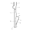
図1及び図2(A)に示す合成樹脂製キャップ(以下、キャップという)1は、例えばペットボトル等の図示しない容器の口部に装着されて使用されるものであり、コンプレッション成形又はインジェクション成形によって、ポリエチレンで一体的に成形されている。なお、キャップ1を形成する素材は、特に限定されるものではなく、本実施形態で用いたポリエチレンの他、ポリプロピレン等が好適に用いられる。 A synthetic resin cap (hereinafter referred to as a cap) 1 shown in FIG. 1 and FIG. 2A is used by being attached to a mouth portion of a container (not shown) such as a PET bottle, for example, and compression molding or injection molding. Are integrally formed of polyethylene. In addition, the raw material which forms the cap 1 is not specifically limited, Polypropylene etc. other than the polyethylene used by this embodiment are used suitably.
そして、キャップ1は、平面視において略円形状の天壁2と、この天壁2の外周部から下向きに延びる略円筒状のスカート壁3を有している。ここで、スカート壁3の外周面にはローレット溝4を、内周面には雌ねじ5を設けてあり、この雌ねじ5は容器口部の外周に形成された雄ねじ(図示していない)に結合可能である。
The cap 1 has a substantially
また、キャップ1は、未開封(開栓が一度もされていないこと)を証明する機能を有するピルファープルーフキャップであり、スカート壁3の下部には、スカート壁3の全周にわたって延びる環状弱化部6を介してタンパーエビデンスバンド(以下、単に「バンド」という)7を連結してある。
The cap 1 is a pill fur-proof cap that has a function of proving that it has not been opened (that has never been opened), and the lower part of the
すなわち、環状弱化部6は、スカート壁3とバンド7とを上下に画するものであり、スカート壁3及びバンド7の周方向に断続して延びる(ミシン目状の)スリットと、隣り合うスリットの間に存在するブリッジとで構成され、ブリッジは所定の力で引っ張られると破断する。
In other words, the annular weakening 6 defines the
そして、このバンド7の内周側には、内向きに突出し、内側への突出量が上側ほど増大するように構成されたフック8を、周方向に間隔をおいて複数(例えば9個)設けてある。各フック8は、キャップ1が容器口部に装着された状態で、容器口部の外周において雄ねじよりも下方に形成された図示しない環状突起(ビード部)の略下側へ位置し、開栓操作によって当該環状突起に係止する。すなわち、フック8は、環状突起に下方から係止可能に構成されている。
A plurality of hooks 8 (for example, nine) are provided on the inner peripheral side of the
また、バンド7の内周側において、フック8の上方には、容器口部への装着過程において環状突起の外周面に当接する当接部9が設けられている。この当接部9は、バンド7の周方向に延び、全周にわたって連続して設けられている。そして、容器口部に装着されたキャップ1を開栓する際、容器口部の環状突起の外周面に当接部9が当接することにより、キャップ1が斜めに持ち上がることが防止され、環状弱化部6が偏らずに略均一に破断するので、タンパーエビデンス性は良好となる。
In addition, on the inner peripheral side of the
さらに、バンド7の内周側において、フック8の下端は、バンド7の下端から1.0mm以内に位置している。換言すると、バンド7の下端からフック8の下端までの距離(バンド7の軸方向の距離)d(図3参照)は、1.0mm以下であり、本例の距離dは0.4mmである。これにより、キャップ1を容器口部に装着(キャッピング)する際、仮に容器口部が比較的肉薄であるバンド7の下端部(バンド7の下端からフック8の下端までの部分)7aに接触した場合でも、バンド7の下端部7aは短いので内側に折れ曲がって破損し難くなっている。しかも、図3に示すように、バンド7の下端部7aの内周側に、先端側ほど内径が大きくなり、フック8に近づくほど内径が小さくなる湾曲面ないし傾斜面を設けておくことにより、この湾曲面ないし傾斜面が容器口部をバンド7の内側へガイド(センタリング)することになるので、上記破損の防止の確実化を図ることができる。
Further, on the inner peripheral side of the
また、バンド7の内周面においてフック8が設けられていない部分の当接部9から下端部7aまでの形状は、図3に一点鎖線で示すように、上下にストレートに延びている一方、フック8の縦断面は、バンド7の軸方向に延びる縦辺8aと、この縦辺8aの上端からバンド7の内側に向かって延び縦辺8aに直交する横辺8bと、縦辺8a及び横辺8bをつなぐ斜辺8cとを有する略直角三角形状を呈する。そして、縦辺8aと斜辺8cとがなす角度θは1°〜30°、好ましくは10°〜30°であり、本例では20°にしてある。
In addition, the shape from the contact portion 9 to the
一方、本例のキャップ1は、図1に示すように、スカート壁3の上部からバンド7の下部にまで延びる通し溝10を複数有し、各通し溝10は、スカート壁3の雌ねじ5を分断し、隣り合うフック8の間を通るように延びている。ここで、雌ねじ5は、スカート壁3の内周面を螺旋状に周回するねじ山によって構成され、各通し溝10によって周方向に等間隔に分断されている。すなわち、スカート壁3の内周面には、通し溝10と、この通し溝10により分断されたねじ山片11が存在するねじ領域12とが周方向に交互に並ぶ。
On the other hand, the cap 1 of this example has a plurality of through
ここで、本例の雌ねじ5を構成するねじ山は、スカート壁3の内周面を螺旋状に二周していて、各ねじ領域12には上下二段のねじ山片11A,11Bが存在する(図4参照)。また、各ねじ領域12の下方に一つのフック8が位置し、上段ねじ山片11Aの横幅が最も小さく、下段ねじ山片11Bとフック8の横幅は略同一であり、本例では下段ねじ山片11Bの横幅がフック8の横幅より若干大きくなっている。また、スカート壁3の内周面からの突出量は、上段ねじ山片11Aと下段ねじ山辺11Bでは同一であり、これらの突出量に比べてフック8の突出量は小さくなっている(図2(A)及び(B)参照)。
Here, the screw thread constituting the
このような構成により、本例のキャップ1を成形後、金型からの無理抜きに伴う成形不良を抑えることができる。すなわち、キャップ1の成形の際、金型に注入した溶融樹脂の冷却後に、成形品の型抜きを行うのであるが、キャップ1の内周面に設けられた雌ねじ5(ねじ山片11)やフック8は、成形品を金型から抜く際のアンダーカット部になっているため、成形品を金型から取り出すためには、成形品のバンド7側から払い出してアンダーカット部であるねじ山片11及びフック8の無理抜きが必要となる。そして、本例のキャップ1では、キャップ1の内周面において、アンダーカット部となるねじ山片11及びフック8の周方向の位置を揃えているので、離型抵抗を総合的に小さくすることができ、その結果、成形不良が抑えられることになる。
With such a configuration, after molding the cap 1 of this example, it is possible to suppress molding defects caused by forced removal from the mold. That is, when the cap 1 is molded, after the molten resin injected into the mold is cooled, the molded product is die-cut. The female screw 5 (thread piece 11) provided on the inner peripheral surface of the cap 1 Since the
また、バンド7に設けるフック8の数は、7個以上19個以下の奇数個とするのが好ましく、本例では9個である。ここで、フック8が5個以下であると、容器口部の外周の環状突起への係止を十分に行わせるために各フック8に必要となる横幅及び突出量が大きくなり、上述した離型抵抗の上昇を招来する。また、フック8が21個以上であると、各フック8に十分な横幅及び突出量を持たせるのが困難となり、容器口部の外周の環状突起への係止が不十分となる恐れがある。そして、フック8が偶数個であると、バンド7の内周面においてフック8が存在しない部位どうしが対向する箇所が形成されてしまい、これにより、環状突起への係止力が弱くなる場合が生じる恐れがあるが、本例ではフック8を奇数個とすることにより、上記のような箇所が形成されず、環状突起への係止力が十分に保たれることになる。
Further, the number of
なお、本発明は、上記の実施の形態に何ら限定されず、本発明の要旨を逸脱しない範囲において種々に変形して実施し得ることは勿論である。例えば、以下のような変形例を挙げることができる。 In addition, this invention is not limited to said embodiment at all, Of course, it can change and implement variously in the range which does not deviate from the summary of this invention. For example, the following modifications can be given.
図4には、雌ねじ5を構成するねじ山が、スカート壁3の内周面を螺旋状に二周していて、各ねじ領域12には上下二段のねじ山片11A,11Bが存在する例を示しているが、雌ねじ5を構成するねじ山の周回数は、二周未満でも二周超でもよく、これに伴って、各ねじ領域12に存在するねじ山片11の数は一つでも三つ以上でもよい。
In FIG. 4, the screw thread constituting the
図1には、上段ねじ山片11Aより下段ねじ山片11Bのほうが横幅が広い例を示しているが、これに限らず、例えば両者11A,11Bの横幅は同一でもよい。
FIG. 1 shows an example in which the
図1には、通し溝10によって雌ねじ5を分断する例を示しているが、雌ねじ5を分断せず、通し溝10をバンド7のみに設けるようにしてもよい。
FIG. 1 shows an example in which the
図1には、キャップ1が別体のパッキンを持たないいわゆる1ピースキャップである例を示しているが、これに限らず、キャップ1は、別体のパッキンを有するいわゆる2ピースキャップであってもよい。 Although FIG. 1 shows an example in which the cap 1 is a so-called one-piece cap that does not have a separate packing, the cap 1 is not limited to this, and the cap 1 is a so-called two-piece cap having a separate packing. Also good.
上記実施形態の雌ねじ5は3条ねじであるが、これに限らず、雌ねじ5が1条ねじ、2条ねじ等であってもよい。
Although the
なお、上記変形例どうしを適宜組み合わせてもよいことはいうまでもない。 Needless to say, the above modifications may be combined as appropriate.
1 キャップ
2 天壁
3 スカート壁
4 ローレット溝
5 雌ねじ
6 環状弱化部
7 バンド
8 フック
8a 縦辺
8b 横辺
8c 斜辺
9 当接部
10 通し溝
11 ねじ山片
11A 上段ねじ山片
11B 下段ねじ山片
12 ねじ領域
θ 角度
DESCRIPTION OF SYMBOLS 1
Claims (3)
前記タンパーエビデンスバンドの内周側に、前記容器口部の外周に設けられた環状突起に下方から係止可能なフックが周方向に間隔をおいて複数設けられ、
また、前記タンパーエビデンスバンドの内周側において、前記フックの上方には、前記環状突起の外周面に当接する当接部が設けられ、
さらに、前記タンパーエビデンスバンドの内周側において、前記フックの下端は、前記タンパーエビデンスバンドの下端から1.0mm以内に位置していることを特徴とする合成樹脂製キャップ。 A cap provided with a skirt wall provided with an internal thread that engages with an external thread formed on the outer periphery of the container mouth portion, and a tamper evidence band connected to the lower portion of the skirt wall via an annular weakening portion,
On the inner peripheral side of the tamper evidence band, a plurality of hooks that can be locked from below on annular protrusions provided on the outer periphery of the container mouth portion are provided at intervals in the circumferential direction,
Further, on the inner peripheral side of the tamper evidence band, a contact portion that contacts the outer peripheral surface of the annular protrusion is provided above the hook,
Furthermore, on the inner peripheral side of the tamper evidence band, the lower end of the hook is located within 1.0 mm from the lower end of the tamper evidence band.
Priority Applications (1)
| Application Number | Priority Date | Filing Date | Title |
|---|---|---|---|
| JP2016003476A JP2017124837A (en) | 2016-01-12 | 2016-01-12 | Synthetic resin cap |
Applications Claiming Priority (1)
| Application Number | Priority Date | Filing Date | Title |
|---|---|---|---|
| JP2016003476A JP2017124837A (en) | 2016-01-12 | 2016-01-12 | Synthetic resin cap |
Publications (1)
| Publication Number | Publication Date |
|---|---|
| JP2017124837A true JP2017124837A (en) | 2017-07-20 |
Family
ID=59364948
Family Applications (1)
| Application Number | Title | Priority Date | Filing Date |
|---|---|---|---|
| JP2016003476A Pending JP2017124837A (en) | 2016-01-12 | 2016-01-12 | Synthetic resin cap |
Country Status (1)
| Country | Link |
|---|---|
| JP (1) | JP2017124837A (en) |
Cited By (2)
| Publication number | Priority date | Publication date | Assignee | Title |
|---|---|---|---|---|
| WO2019003826A1 (en) | 2017-06-27 | 2019-01-03 | ソニーセミコンダクタソリューションズ株式会社 | Image capture device, vehicle use system, and vehicle surveillance system |
| JP7138815B1 (en) * | 2022-03-18 | 2022-09-16 | 日本山村硝子株式会社 | cap |
Citations (7)
| Publication number | Priority date | Publication date | Assignee | Title |
|---|---|---|---|---|
| JPH01107557U (en) * | 1987-12-31 | 1989-07-20 | ||
| JPH03133750A (en) * | 1989-07-13 | 1991-06-06 | Mcg Closures Ltd | Closing member |
| JPH04100451U (en) * | 1991-02-02 | 1992-08-31 | ||
| JP2003095298A (en) * | 1992-07-16 | 2003-04-03 | Closures & Packaging Services Ltd | Cap for tamper evident |
| JP2011136728A (en) * | 2009-12-28 | 2011-07-14 | Csi Japan:Kk | Synthetic resin-made cap, closing device, and closing device containing beverage |
| JP2013189246A (en) * | 2012-02-14 | 2013-09-26 | Nihon Yamamura Glass Co Ltd | Resin cap |
| JP2015040052A (en) * | 2013-08-21 | 2015-03-02 | 株式会社西秋工作所 | Bottle type resin container |
-
2016
- 2016-01-12 JP JP2016003476A patent/JP2017124837A/en active Pending
Patent Citations (7)
| Publication number | Priority date | Publication date | Assignee | Title |
|---|---|---|---|---|
| JPH01107557U (en) * | 1987-12-31 | 1989-07-20 | ||
| JPH03133750A (en) * | 1989-07-13 | 1991-06-06 | Mcg Closures Ltd | Closing member |
| JPH04100451U (en) * | 1991-02-02 | 1992-08-31 | ||
| JP2003095298A (en) * | 1992-07-16 | 2003-04-03 | Closures & Packaging Services Ltd | Cap for tamper evident |
| JP2011136728A (en) * | 2009-12-28 | 2011-07-14 | Csi Japan:Kk | Synthetic resin-made cap, closing device, and closing device containing beverage |
| JP2013189246A (en) * | 2012-02-14 | 2013-09-26 | Nihon Yamamura Glass Co Ltd | Resin cap |
| JP2015040052A (en) * | 2013-08-21 | 2015-03-02 | 株式会社西秋工作所 | Bottle type resin container |
Cited By (2)
| Publication number | Priority date | Publication date | Assignee | Title |
|---|---|---|---|---|
| WO2019003826A1 (en) | 2017-06-27 | 2019-01-03 | ソニーセミコンダクタソリューションズ株式会社 | Image capture device, vehicle use system, and vehicle surveillance system |
| JP7138815B1 (en) * | 2022-03-18 | 2022-09-16 | 日本山村硝子株式会社 | cap |
Similar Documents
| Publication | Publication Date | Title |
|---|---|---|
| JP2018177302A (en) | Plug | |
| WO2017061001A1 (en) | Synthetic resin cap | |
| JP6204621B1 (en) | Synthetic resin caps and containers | |
| WO2019058552A1 (en) | Synthetic resin cap and container | |
| JP2017124837A (en) | Synthetic resin cap | |
| JP6180687B1 (en) | Synthetic resin caps and containers | |
| JP6534501B2 (en) | Plastic container lid | |
| JP6539011B1 (en) | Synthetic resin cap and container | |
| JP6775996B2 (en) | Synthetic resin container lid | |
| JP7117981B2 (en) | Synthetic resin cap | |
| JP6564141B2 (en) | Plastic cap | |
| JP5918450B1 (en) | Synthetic resin caps and containers | |
| WO2020179608A1 (en) | Cap | |
| JP2010260583A (en) | Synthetic resin cap of forced fit type | |
| WO2017043200A1 (en) | Synthetic resin cap | |
| JP7117982B2 (en) | Synthetic resin cap | |
| JP7409813B2 (en) | Synthetic resin cap | |
| JP7005267B2 (en) | Synthetic resin caps and containers | |
| JP7348789B2 (en) | Synthetic resin cap | |
| JP6306806B1 (en) | Synthetic resin caps and containers | |
| CN112566852B (en) | Synthetic resin end cap | |
| JP7037915B2 (en) | Synthetic resin caps and containers | |
| WO2019073794A1 (en) | Synthetic resin cap and container | |
| JP2015077999A (en) | Resin cap | |
| JP2020015558A (en) | Synthetic resin container lid |
Legal Events
| Date | Code | Title | Description |
|---|---|---|---|
| A621 | Written request for application examination |
Free format text: JAPANESE INTERMEDIATE CODE: A621 Effective date: 20181002 |
|
| A977 | Report on retrieval |
Free format text: JAPANESE INTERMEDIATE CODE: A971007 Effective date: 20190612 |
|
| A131 | Notification of reasons for refusal |
Free format text: JAPANESE INTERMEDIATE CODE: A131 Effective date: 20190618 |
|
| A521 | Request for written amendment filed |
Free format text: JAPANESE INTERMEDIATE CODE: A523 Effective date: 20190806 |
|
| A131 | Notification of reasons for refusal |
Free format text: JAPANESE INTERMEDIATE CODE: A131 Effective date: 20190910 |
|
| A02 | Decision of refusal |
Free format text: JAPANESE INTERMEDIATE CODE: A02 Effective date: 20200303 |