電動ステアリングロック装置の斜視図である。It is a perspective view of an electric steering lock device.
電動ステアリングロック装置の分解斜視図である。It is a disassembled perspective view of an electric steering lock device.
カバーを省略した状態での図1の3矢視図である。FIG. 3 is a view taken in the direction of arrow 3 in FIG. 1 with a cover omitted.
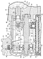
図3の4−4線断面図である。FIG. 4 is a cross-sectional view taken along line 4-4 of FIG.
図3の5−5線断面図である。FIG. 5 is a sectional view taken along line 5-5 of FIG.
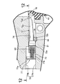
ロックピンが係合位置にある状態での図3の6−6線断面図である。FIG. 6 is a cross-sectional view taken along line 6-6 in FIG. 3 in a state where the lock pin is in the engaged position.
図5の7−7線断面図である。FIG. 7 is a cross-sectional view taken along line 7-7 in FIG. 5 .
カバーをボディ側から見た斜視図である。It is the perspective view which looked at the cover from the body side.
カバーをボディ側から見た正面図である。It is the front view which looked at the cover from the body side.
図9の10−10線断面図である。FIG. 10 is a sectional view taken along line 10-10 in FIG. 9;
ロックピンが係合位置にある状態での図4の11−11線断面図である。It is the 11-11 line sectional view of Drawing 4 in the state where a lock pin exists in an engagement position.
トリガピンおよびロック保持部材の作動状態を図11の12−12線に沿って示す断面図である。It is sectional drawing which shows the operating state of a trigger pin and a lock holding member along the 12-12 line of FIG.
締結部に関してトリガーピン固設部と反対側からの外力がカバーに作用したときの締結部での力の流れを図9に対応して(a)で示すとともにカバーの破断状況を図3に対応して(b)で示す図である。With respect to the fastening part, the flow of force at the fastening part when an external force from the side opposite to the trigger pin fixing part acts on the cover is shown in FIG. It is a figure shown by (b).
上方からカバーに外力が作用したときの締結部での力の流れを図9に対応して示す図である。It is a figure which shows the flow of the force in a fastening part when external force acts on a cover from upper direction corresponding to FIG.
締結部に関してトリガーピン固設部側からの外力がカバーに作用したときの締結部での力の流れを図9に対応して示す図である。It is a figure which shows the flow of the force in a fastening part when the external force from the trigger pin fixed part side acts on a cover regarding a fastening part corresponding to FIG.
下方からカバーに外力が作用したときの締結部での力の流れを図9に対応して(a)で示すとともにカバーの破断状況を図3に対応して(b)で示す図である。FIG. 10A is a diagram illustrating the flow of force at the fastening portion when an external force is applied to the cover from below, corresponding to FIG. 9A, and FIG.
この実施の形態では、前記摺動孔26の上方で該摺動孔26と平行に延びて前記カバー22側および前記摺動孔26側に開放したカバー装着孔46がボディ21に形成されており、前記ボディ21の上面21cと、前記ロックピン18との間に介在する平板状の第1のプロテクトカバー45が、前記ロックピン18をその上方から覆うようにして前記カバー装着孔46内に挿入される。しかも前記カバー装着孔46の前記カバー22とは反対側の一端部は第1のプロテクトカバー45を圧入するように形成されており、前記カバー装着孔46の前記カバー22側の端部で前記ボディ21には、前記カバー装着孔46の一端部に圧入、保持される第1のプロテクトカバー45の上下方向でのがたつきを抑制するために、前記ロックピン18とは反対側の一面に当接して第1のプロテクトカバー45の他面をボディ21側に押しつける一対の突部47が一体に突設される。すなわち第1のプロテクトカバー45は、カバー装着孔46に圧入、固定されることになる。
In this embodiment, the body 21 is formed with a cover mounting hole 46 that extends in parallel with the sliding hole 26 above the sliding hole 26 and opens to the cover 22 side and the sliding hole 26 side. A flat plate-like first protect cover 45 interposed between the upper surface 21c of the body 21 and the lock pin 18 is inserted into the cover mounting hole 46 so as to cover the lock pin 18 from above. Is done. Moreover, one end portion of the cover mounting hole 46 opposite to the cover 22 is formed so as to press-fit the first protect cover 45, and the body portion is formed at the end portion of the cover mounting hole 46 on the cover 22 side. 21, in order to suppress the backlash in the vertical direction of the first protect cover 45 that is press-fitted and held in one end portion of the cover mounting hole 46, it is applied to one surface opposite to the lock pin 18. A pair of projecting portions 47 that are in contact with each other and press the other surface of the first protect cover 45 toward the body 21 are integrally projected. That is, the first protect cover 45 is press-fitted and fixed in the cover mounting hole 46.
一方、横断面形状を矩形とした前記トリガーピン78は、前記ボス80にねじ部材83で螺合されるとともに第1および第2位置決めピン81,82が挿通されるようにしたベース部78aを一体に有しており、前記トリガーピン固設部79に前記ベース部78aが固定されることで前記トリガーピン78が前記カバー22に固設される。すなわちこの実施の形態では、前記カバー22とは別部材である前記トリガーピン78が前記カバー22に固定されるのであるが、前記トリガーピン78が前記カバー22と一体に形成されるものであってもよい。
On the other hand, the trigger pin 78 having a rectangular cross section has a base portion 78a that is screwed into the boss 80 with a screw member 83 and through which the first and second positioning pins 8 1 and 82 are inserted. The trigger pin 78 is fixed to the cover 22 by fixing the base portion 78 a to the trigger pin fixing portion 79. That is, in this embodiment, the trigger pin 78 which is a separate member from the cover 22 is fixed to the cover 22, but the trigger pin 78 is formed integrally with the cover 22. Also good.