JP6487857B2 - Electric steering lock device - Google Patents
Electric steering lock device Download PDFInfo
- Publication number
- JP6487857B2 JP6487857B2 JP2016004718A JP2016004718A JP6487857B2 JP 6487857 B2 JP6487857 B2 JP 6487857B2 JP 2016004718 A JP2016004718 A JP 2016004718A JP 2016004718 A JP2016004718 A JP 2016004718A JP 6487857 B2 JP6487857 B2 JP 6487857B2
- Authority
- JP
- Japan
- Prior art keywords
- cover
- lock
- pin
- lock pin
- engagement
- Prior art date
- Legal status (The legal status is an assumption and is not a legal conclusion. Google has not performed a legal analysis and makes no representation as to the accuracy of the status listed.)
- Active
Links
- 230000033001 locomotion Effects 0.000 claims description 33
- 238000006243 chemical reaction Methods 0.000 claims description 10
- 238000003780 insertion Methods 0.000 description 4
- 230000037431 insertion Effects 0.000 description 4
- 239000007769 metal material Substances 0.000 description 3
- 239000010960 cold rolled steel Substances 0.000 description 2
- 230000001681 protective effect Effects 0.000 description 2
- 229920003002 synthetic resin Polymers 0.000 description 2
- 239000000057 synthetic resin Substances 0.000 description 2
- 229910000861 Mg alloy Inorganic materials 0.000 description 1
- 210000000078 claw Anatomy 0.000 description 1
- 238000010586 diagram Methods 0.000 description 1
- 238000009434 installation Methods 0.000 description 1
- 229910001234 light alloy Inorganic materials 0.000 description 1
- 229910052751 metal Inorganic materials 0.000 description 1
- 239000002184 metal Substances 0.000 description 1
- 239000010935 stainless steel Substances 0.000 description 1
- 229910001220 stainless steel Inorganic materials 0.000 description 1
Images


Landscapes
- Lock And Its Accessories (AREA)
Description
本発明は、ステアリングシャフトを囲繞するステアリングコラムに固定されるボディに該ボディの開口端を閉じるカバーが締結されて成るハウジングと、前記ステアリングシャフトに係合する係合位置ならびにその係合を解除する係合解除位置間での直線的な往復移動を可能として前記ボディに支持されるロックピンと、当該ロックピンを駆動する動力を発揮することを可能として前記ハウジング内に収容、固定される電動モータと、当該電動モータの回転運動を前記ロックピンの直線運動に変換するようにして前記ハウジング内で前記電動モータおよび前記ロックピン間に介設される運動変換手段と、前記ロックピンが前記係合位置にある状態を保持するロック保持位置ならびに前記ロックピンが前記係合解除位置側に移動することを可能としたロック保持解除位置間で作動することを可能として前記ボディに支持されるとともにロック保持位置側にばね付勢されるロック保持部材と、前記ロック保持解除位置に在る前記ロック保持部材に係合するようにして前記カバーに固設されるトリガーピンとを備える電動ステアリングロック装置に関する。 The present invention relates to a housing in which a cover that closes an opening end of a body is fastened to a body fixed to a steering column that surrounds the steering shaft, an engagement position that engages with the steering shaft, and the engagement is released. A lock pin that is supported by the body to enable linear reciprocation between the disengagement positions, and an electric motor that is housed and fixed in the housing so as to be able to exert power to drive the lock pin A motion converting means interposed between the electric motor and the lock pin in the housing so as to convert the rotational motion of the electric motor into a linear motion of the lock pin, and the lock pin is in the engagement position. It is possible to move the lock pin and the lock pin to the disengagement position side for holding the state at Engaged with the lock holding member that is supported by the body and is spring-biased to the lock holding position side, and that can be operated between the lock holding release positions, and the lock holding member at the lock holding release position Thus, the present invention relates to an electric steering lock device including a trigger pin fixed to the cover.
このような電動ステアリングロック装置は、特許文献1等で既に知られており、このものでは、カバーに、トリガーピンのカバーへの固設部を囲むインナー脆弱部と、一部がインナー脆弱部を兼ねるようにしてインナー脆弱部を囲むアウター脆弱部と、ボディ側への嵌合部に2条づつ配置されるリニア脆弱部とが形成されている。 Such an electric steering lock device is already known from Patent Document 1 and the like. In this device, the cover includes an inner fragile portion surrounding a fixed portion of the trigger pin to the cover, and a part of the inner fragile portion. An outer fragile portion that surrounds the inner fragile portion and a linear fragile portion that is arranged two by two at the fitting portion to the body side are formed.
ところが上記特許文献1で開示されたものでは、カバーに外力が加わったときに、カバーのうちインナー脆弱部で囲まれる部分すなわちトリガーピンのカバーへの固設部を除く部分がボディから離脱した状態となる可能性があり、そうなると、トリガーピンはロック保持部材に係合したままであり、ロックピンをステアリングシャフトに係合した係合位置に保持できず、ステアリングロック状態が不正に解除されてしまう可能性がある。 However, in the case disclosed in Patent Document 1, when an external force is applied to the cover, the portion surrounded by the inner fragile portion of the cover, that is, the portion excluding the portion fixed to the trigger pin cover is detached from the body. In that case, the trigger pin remains engaged with the lock holding member, and the lock pin cannot be held in the engagement position engaged with the steering shaft, and the steering lock state is illegally released. there is a possibility.
本発明は、かかる事情に鑑みてなされたものであり、外力の作用に応じてカバーが破断したときにロックピンをステアリングシャフトに係合した係合位置に確実に保持できるようにした電動ステアリングロック装置を提供することを目的とする。 The present invention has been made in view of such circumstances, and an electric steering lock that can reliably hold a lock pin in an engagement position engaged with a steering shaft when the cover is broken in response to the action of an external force. An object is to provide an apparatus.
上記目的を達成するために、本発明は、ステアリングシャフトを囲繞するステアリングコラムに固定されるボディに該ボディの開口端を閉じるカバーが締結されて成るハウジングと、前記ステアリングシャフトに係合する係合位置ならびにその係合を解除する係合解除位置間での直線的な往復移動を可能として前記ボディに支持されるロックピンと、当該ロックピンを駆動する動力を発揮することを可能として前記ハウジング内に収容、固定される電動モータと、当該電動モータの回転運動を前記ロックピンの直線運動に変換するようにして前記ハウジング内で前記電動モータおよび前記ロックピン間に介設される運動変換手段と、前記ロックピンが前記係合位置にある状態を保持するロック保持位置ならびに前記ロックピンが前記係合解除位置側に移動することを可能としたロック保持解除位置間で作動することを可能として前記ボディに支持されるとともにロック保持位置側にばね付勢されるロック保持部材と、前記ロック保持解除位置に在る前記ロック保持部材に係合するようにして前記カバーに固設されるトリガーピンとを備える電動ステアリングロック装置において、前記カバーに、前記ボディに締結解除不能に締結される単一の締結部が形成されるとともに、前記トリガーピンの前記カバーへの固設部であるトリガーピン固設部が配設され、前記カバーへの外力の作用に応じて破断して前記カバーのうち前記トリガーピン固設部を少なくとも含む部分を前記ボディから離脱させる脆弱部が前記締結部に形成されることを特徴とする。 In order to achieve the above object, the present invention provides a housing in which a cover that closes an opening end of a body is fastened to a body that is fixed to a steering column that surrounds the steering shaft, and an engagement that engages with the steering shaft. A lock pin supported by the body that enables linear reciprocation between the position and the disengagement position that releases the engagement, and power that drives the lock pin can be exerted in the housing. An electric motor that is housed and fixed, and a motion conversion means that is interposed between the electric motor and the lock pin in the housing so as to convert the rotational motion of the electric motor into a linear motion of the lock pin; A lock holding position for holding the lock pin in the engaged position, and the lock pin being disengaged. A lock holding member supported by the body and spring-biased to the lock holding position side so as to be able to operate between the lock holding release positions that can move to the installation side; and to the lock holding release position In the electric steering lock device comprising a trigger pin fixed to the cover so as to engage with the existing lock holding member, the cover has a single fastening portion fastened to the body so as not to be unfastened. And a trigger pin fixing portion, which is a fixing portion of the trigger pin to the cover, is disposed, and is broken according to the action of an external force on the cover, and the trigger pin fixing portion of the cover is fixed. A fragile part for separating a part including at least a part from the body is formed in the fastening part.
本発明の上記特徴によれば、外力がカバーに作用するのに応じて、カバーをボディに締結解除不能に締結するための単一の締結部に形成される脆弱部で破断し、カバーのうちトリガーピン固設部を少なくとも含む部分がボディから離脱するので、ロック保持部材へのトリガーピンの係合が解除され、ロック保持位置側に付勢されているロック保持部材がロック保持解除位置からロック保持位置に移動することで、ロックピンが係合位置にある状態すなわちステアリングロック状態を確実に保持することができ、ステアリングロック状態が不正に解除されることを防止することができる。 According to the above feature of the present invention, in response to an external force acting on the cover, the cover breaks at the weakened portion formed in the single fastening portion for fastening the cover to the body so as not to be unfastened. Since the part including at least the trigger pin fixing part is detached from the body, the engagement of the trigger pin with the lock holding member is released, and the lock holding member biased to the lock holding position side is locked from the lock holding release position. By moving to the holding position, the state where the lock pin is in the engagement position, that is, the steering lock state can be reliably held, and the steering lock state can be prevented from being illegally released.
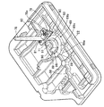
以下、本発明の実施の形態を、添付の図1〜図16を参照しながら説明すると、先ず図1において、この電動ステアリングロック装置は、たとえばスマートエントリーシステムにおいて、携帯送・受信器を携帯した車両ユーザが車両に乗り込むのに応じてステアリングシャフト15の回動を可能とすべくステアリングロック状態を解除し、前記携帯送・受信器を携帯した車両ユーザが車両から退出するのに応じてステアリングシャフト15の回動を阻止すべくステアリングロック状態となるように作動するものである。
Hereinafter, an embodiment of the present invention will be described with reference to FIG. 1 to FIG. 16. First, in FIG. 1, this electric steering lock device carries a portable transmitter / receiver in a smart entry system, for example. The steering shaft is released so that the
図2〜図6を併せて参照して、前記電動ステアリングロック装置は、前記ステアリングシャフト15を囲繞する円筒状のステアリングコラム16に固定されるハウジング17と、前記ステアリングシャフト15に係合する係合位置およびその係合を解除する係合解除位置間での直線的な往復移動を可能として前記ハウジング17に支持されるロックピン18と、当該ロックピン18を駆動する動力を発揮することを可能として前記ハウジング17内に収容、固定される電動モータ19と、電動モータ19の回転運動を前記ロックピン18の直線運動に変換するようにして前記ハウジング17内で前記電動モータ19および前記ロックピン18間に介設される運動変換手段20とを備える。
2 to 6, the electric steering lock device includes a
前記ハウジング17は、ステアリングコラム16とは反対側を開放した有底筒状のボディ21と、該ボディ21の開口端を閉じるようにして前記ボディ21に締結されるカバー22とから成り、前記ボディ21および前記カバー22は、たとえばマグネシウム合金等の軽合金によって鋳造成形される。
The
前記ボディ21の前記ステアリングコラム16に対向する面21aは、前記ステアリングコラム16のほぼ半周を嵌合させるようにして半円形の横断面形状を有するように形成されており、この面21aから突出する突部21bが、図5で示すように、前記ステアリングコラム16の側壁に設けられた嵌合孔23に嵌合するようにして前記ボディ21に一体に突設される。また前記ステアリングコラム16は、前記ボディ21と、円弧状のホルダ24とで挟まれており、前記ホルダ24の両端部がねじ部材25で前記ボディ21に締結されることで、前記ボディ21すなわち前記ハウジング17が前記ステアリングコラム16に固定される。しかも前記突部21bを含む部分で前記ボディ21には、前記係合位置および前記係合解除位置間での直線的な摺動を可能として前記ロックピン18を嵌合させる摺動孔26が設けられ、前記ステアリングシャフト15の外周には前記ロックピン18を係合させ得る複数の係合凹部27が設けられており、それらの係合凹部27の1つに前記ロックピン18を係合させることでステアリングロック状態が得られる。
A
前記電動モータ19は、前記摺動孔26の一側で前記ボディ21に形成されて前記カバー22側に開放したモータ収容凹部28に収容され、前記電動モータ19の一部を覆う円弧状のブラケット29が前記ボディ21に締結されることで前記ボディ21に固定され、前記ハウジング17内に収容される。前記ブラケット29の一端部は、締め付け方向のみに回転操作することを可能としたワンウエイの第1ボルト30で前記ボディ21に締結され、前記ブラケット29の他端部は、締め付け方向のみに回転操作することを可能としたワンウエイの第2ボルト31で前記ボディ21に締結されており、前記ブラケット29は締結解除を不能として前記ボディ21に締結される。しかも前記ブラケット29は、外部からの力の作用によって破壊されることを防止するために、高強度の非磁性金属材料たとえばステンレス鋼によって形成される。
The
前記運動変換手段20は、前記電動モータ19の出力軸34に設けられるウォームギヤ35と、該ウォームギヤ35に噛合するウォームホイル36と、該ウォームホイル36とともに回転するねじ軸37と、軸線まわりの回転が規制されるとともに軸線方向の移動が許容されて前記ねじ軸37に螺合するナット38とで構成され、前記ハウジング17内に収容される。
The motion converting means 20 includes a
前記ねじ軸37は、前記ロックピン18にその下方で隣接した位置に配置されて当該ロックピン18の移動方向と平行な軸線を有しており、このねじ軸37の軸方向に沿う中間部の外周に雄ねじ39が刻設される。また前記雄ねじ39よりも前記カバー22側で前記ねじ軸37に前記ウォームホイル36が固定される。
The
前記雄ねじ39に螺合するねじ孔40を有する前記ナット38は、合成樹脂から成るスライダ41にモールド結合されており、このスライダ41は、前記ロックピン18の移動方向と平行な方向への直線的な移動を可能とするものの前記ねじ孔40の軸線すなわち前記ねじ軸37の軸線まわりに回転するのは規制されるようにして前記ボディ21に摺動可能に嵌合される。
The
前記ナット38には、前記スライダ41から前記ロックピン18側に突出する連結腕部38aが一体に設けられる。一方、前記ロックピン18には、前記連結腕部38aを両側から挟むようにして平行に延びる一対の延出壁部18aが一体に設けられており、それらの延出延出壁部18aに形成されて前記ロックピン18の移動方向に長く延びる長孔42に、前記連結腕部38aに挿通された規制ピン43の両端部が挿通される。したがって前記規制ピン43が前記長孔42内を移動する範囲で前記ロックピン18は前記スライダ41および前記ナット38に対して前記ねじ軸37の軸方向に相対移動可能である。また前記連結腕部38aおよび前記ロックピン18間には、前記ロックピン18を前記係合位置側に付勢する第1のコイルばね44が介設される。
The
このような運動変換手段20および前記ロックピン18の連結構造によれば、前記ロックピン18が係合解除位置にある状態で前記電動モータ19の回転作動によって前記ナット38が前記スライダ41とともに軸方向に移動すると、圧縮される第1のコイルばね44のばね力で前記ロックピン18が係合位置側に向けて移動し、ステアリングシャフト15の外周に形成された複数の係合凹部27の1つに前記ロックピン18が係合することになる。この際、前記ロックピン18が複数の係合凹部27相互間で前記ステアリングシャフト15の外周に接触したときには第1のコイルばね44で前記ロックピン18の移動が阻止された分を吸収し、前記ステアリングシャフト15をわずかに回動操作することで前記ロックピン18を前記係合凹部27に係合することができる。一方、前記ロックピン18が係合位置にある状態で前記電動モータ19が上述とは逆方向に回転作動すると、ナット38の軸方向移動によって前記ロックピン18の延出壁部18aの前記長孔42内を前記規制ピン43が移動し、前記長孔42の前記ステアリングシャフト15とは反対側の端部に規制ピン43が当接してからは、前記ナット38とともに前記ロックピン18が移動し、ロックピン18の係合解除位置で前記電動モータ19の作動が停止する。
According to such a connecting structure of the motion converting means 20 and the
図7を併せて参照して、前記ボディ21の外側面のうち前記ロックピン18からの距離が最も近い外側面(この実施の形態ではボディ21の上面21c)と、前記ロックピン18との間に少なくとも介在する平板状の第1のプロテクトカバー45が、前記ロックピン18をその周囲の少なくとも一部から覆うようにして前記ボディ21内に固定配置される。第1のプロテクトカバー45は、高強度の金属材料たとえば冷間圧延鋼板によって形成される。
Referring also to FIG. 7, the distance between the outer surface of the
この実施の形態では、前記摺動孔26の上方で該摺動孔26と平行に延びて前記カバー22側および前記摺動孔26側に開放したカバー装着孔46がボディ21に形成されており、前記ボディ21の上面21cと、前記ロックピン18との間に介在する平板状の第1のプロテクトカバー45が、前記ロックピン18をその上方から覆うようにして前記カバー装着孔46内に挿入される。しかも前記カバー装着孔46の前記カバー22とは反対側の一端部は第1のプロテクトカバー45を圧入するように形成されており、前記カバー装着孔46の前記カバー22側の端部で前記ボディ21には、前記カバー装着孔46の一端部に圧入、保持される第1のプロテクトカバー45の上下方向でのがたつきを抑制するために、前記ロックピン18とは反対側の一面に当接して第1のプロテクトカバー45の他面をボディ21側に押しつける一対の突部47が一体に突設される。すなわち第1のプロテクトカバー45は、カバー装着孔46に圧入、固定されることになる。
In this embodiment, the
ところで第1のプロテクトカバー45には板ばね49が保持される。第1のプロテクトカバー45の前記カバー22側の端部には、第1のプロテクトカバー45の長手方向に間隔をあけた一対の保持孔50,51が形成されており、前記板ばね49には、一対の前記保持孔50,51に挿入される略U字状の被保持部49aが一体に形成される。すなわち前記板ばね49は、第1のプロテクトカバー45の前記カバー22側の端部に保持されており、前記ロックピン18が係合解除位置にあるときに前記ナット38の前記連結腕部38aに弾発的に当接する。これにより、前記ロックピン18が係合解除位置にあるときの前記ねじ軸37および前記ナット38の螺合状態が保持される。
Incidentally, a
前記ボディ21には、前記カバー22および前記運動変換手段20間に介在する第2のプロテクトカバー52が、前記カバー22側から前記運動変換手段20を覆うようにして締結解除不能に締結され、第2のプロテクトカバー52は、高強度の金属材料たとえば冷間圧延鋼板によって形成される。
A second
第2のプロテクトカバー52は、前記運動変換手段20をカバー22側から覆う平板状のカバー主部52aと、そのカバー主部52aの前記電動モータ19側の下部から下方に延びる第1腕部52bと、第1のプロテクトカバー45を前記カバー22側から覆うようにして前記カバー主部52aから上方に延びる第2腕部52cと、前記カバー主部52aから前記電動モータ19とは反対側に延びる第3腕部52dとを一体に有するように形成される。
The second
第1腕部52bは、前記ブラケット29の他端部に重なるように配置される。この第1腕部52bの上部には、第2ボルト31を挿通させるようにして前記ブラケット29の他端部に形成される挿通孔53の下半部に対応した半円状の凹部54が形成される。すなわち第1腕部52bは前記ブラケット29の他端部との共締めでボディ21に締結されており、第2ボルト31は、締め付け方向のみに回転操作することを可能としたワンウエイのボルトである。また第2腕部52cは、締め付け方向のみに回転操作することを可能としたワンウエイの第3ボルト55で前記ボディ21に締結され、第3腕部52dは、締め付け方向のみに回転操作することを可能としたワンウエイの第4ボルト56で前記ボディ21に締結されており、第2のプロテクトカバー52は、締結解除不能としてボディ21に締結されることになる。
The
第2のプロテクトカバー52には、前記ねじ軸37の一端部を回転自在に支持する有底円筒状の軸受ハウジング57が形成され、前記ボディ21には、前記ねじ軸37の他端部を回転自在に支持する軸受け部材58が嵌合、装着される。
The second
ところで前記電動モータ19の作動を制御するための制御ユニット59が搭載される回路基板60が、前記運動変換手段20に隣接した位置に配置されており、この回路基板60は、合成樹脂製の回路ケース61で前記カバー22側から覆われるようにして該回路ケース61内に複数のねじ部材62で固定される。この実施の形態では、前記電動モータ19および前記運動変換手段20に下方から隣接する位置に前記回路ケース61が配置されており、この回路ケース61の前記カバー22に対向する側面に、前記カバー22に弾発的に当接する一対の弾発当接部63が一体に形成される。また第2のプロテクトカバー52における第1腕部52bには、前記回路ケース61に前記カバー22側から当接する当接腕部52eが一体に形成される。すなわち前記カバー22が前記ボディ21に締結され、第2のプロテクトカバー52が前記ボディ21に締結されることで、前記回路ケース61が前記ボディ21内で固定されることになる。
By the way, a
前記スライダ41の下部には一対のマグネット64が嵌合されており、それらのマグネット64を前記スライダ41に固定するための一対のマグネットホルダ65が、前記スライダ41の下部に取付けられる。一方、前記スライダ41の下方に配置される前記回路基板60上には、前記スライダ41とともに移動する前記マグネット64を検出して前記スライダ41の位置を検出するセンサ(図示せず)が配設される。
A pair of
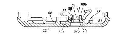
図8〜図10を併せて参照して、前記カバー22の内面には、縦横に交わるリブ68と、第2ボルト31によって該カバー22を前記ボディ21に締結解除不能に締結するための単一の締結部69が形成される。前記締結部69は、第2ボルト31の拡径頭部31aを収容可能として前記カバー22の外面側に開放したボルト収容凹部70を形成するようにして前記カバー22の内面からボディ21側に突出する大径円筒部69aと、第2ボルト31を挿通する挿通孔71を形成するようにして前記大径円筒部69aに同軸に連なる小径円筒部69bと、大径円筒部69aおよび小径円筒部69b間を結ぶ環状段部69cとを一体に有するように形成される。第2ボルト31は、前記締結部69、第2のプロテクトカバー52の第1腕部52bおよび前記ブラケット29の他端部に挿通されて前記ボディ21に螺合されるものであり、前記カバー22、第2のプロテクトカバー52の第1腕部52bおよび前記ブラケット29が、第2ボルト31の共締めで前記ボディ21に締結解除不能に締結されることになる。
Referring to FIGS. 8 to 10 together, the inner surface of the
図11および図12において、前記ボディ21には、図12(a)で示すように前記ロックピン18が前記係合解除位置側に移動することを可能としたロック保持解除位置と、図12(b)で示すように前記ロックピン18が前記係合位置にある状態を保持するロック保持位置との間で作動することを可能としたロック保持部材72が支持されており、このロック保持部材72は、第2のコイルばね73で前記ロック保持位置側にばね付勢される。
11 and 12, the
前記ボディ21には、前記ロックピン18が前記係合位置にある状態で前記スライダ41の側面に一端を対向して開口させたガイド孔74と、そのガイド孔74の他端に一端が連通するとともに他端を前記ボディ21の側面に開口させた圧入孔75とが、前記スライダ41の移動方向と直交する方向に延びるようにして設けられ、前記ガイド孔74は矩形の横断面形状を有するように形成され、前記圧入孔75は、前記ガイド孔74に対応した矩形部75aと、その矩形部75aの上部に連なる半円部75bとから成るドーム形の横断面形状を有するように形成される。
The
前記ロック保持部材72は、前記圧入孔75の前記矩形部75aおよび前記ガイド孔74に摺動可能に嵌合される横断面矩形の摺動部72aと、当該摺動部72aとの間に前記圧入孔75とは反対側に臨む規制段部72bを形成しつつ前記ガイド孔74内を前記運動変換手段20側に延びるようにして前記摺動部72aに連なる偏平板部72cと、前記スライダ41の側面に設けられた係止凹部76に前記ロックピン18が前記係合位置にある状態で係合し得るようにして前記偏平板部72cの先端に連設される係合突部72dとを一体に有するように形成される。
The
前記圧入孔75には、ばね受け部材77が圧入される。このばね受け部材77は、前記圧入孔75の断面形状に対応した形状を有する平板部77aと、その平板部77aの下部に一体に連設されて前記圧入孔75の矩形部75a内を前記ロック保持部材72側に延びる一対の腕部77bとを一体に有するように形成されており、一対の腕部77bにそれぞれ設けられる爪部77cが、前記圧入孔75における前記矩形部75aの内面に食い込むようにして前記ばね受け部材77が前記圧入孔75に圧入される。
A
しかも前記ロック保持部材72の前記摺動部72aには、前記ばね受け部材77側に向けて開放したばね収容凹部85が形成されており、このばね収容凹部85に一部が収容される第2のコイルばね73が、前記ロック保持部材72と、前記ばね受け部材77の前記平板部77aとの間に縮設され、前記ロック保持部材72は、第2のコイルばね73が発揮するばね力によって、前記ロックピン18が前記係合位置にある状態での前記スライダ41の前記係止凹部76に前記係合突部72dを係合させる側すなわちロック保持位置側に付勢される。
In addition, the sliding
前記カバー22には、前記ロック保持解除位置に在る前記ロック保持部材72の前記規制段部72bに係合するトリガーピン78が固設されるものであり、そのトリガーピン78の前記カバー22への固設部であるトリガーピン固設部79が、前記締結部69に一側方から隣接するようにして前記カバー22の内面に配設される。
The
前記トリガーピン固設部79は、円筒状のボス80と、そのボス80の上方に配置される第1位置決めピン81と、前記ボス80を前記締結部69との間に挟む位置に配置される第2位置決めピン82とから成り、前記ボス80、第1位置決めピン81および第2位置決めピン82は前記カバー22と一体に形成される。
The trigger
一方、横断面形状を矩形とした前記トリガーピン78は、前記ボス80にねじ部材83で螺合されるとともに第1および第2位置決めピン81,82が挿通されるようにしたベース部78aを一体に有しており、前記トリガーピン固設部79に前記ベース部78aが固定されることで前記トリガーピン78が前記カバー22に固設される。すなわちこの実施の形態では、前記カバー22とは別部材である前記トリガーピン78が前記カバー22に固定されるのであるが、前記トリガーピン78が前記カバー22と一体に形成されるものであってもよい。
On the other hand, the
前記カバー22に固設された前記トリガーピン78は、前記ボディ21に設けられた横断面矩形の挿入孔84に挿入される。この挿入孔84は、前記ロック保持解除位置に在る前記ロック保持部材72の前記規制段部72bに前記トリガーピン78を係合させる位置で前記ガイド孔74の下部と交差するようにして前記ボディ21に設けられる。したがって前記トリガーピン78が前記カバー22とともに前記ボディ21から離脱すると、前記ロック保持解除位置にある前記ロック保持部材72は第2のコイルばね73のばね力でロック保持位置側に移動することになり、前記ロックピン18が前記係合位置にある状態での前記スライダ41の前記係止凹部76に前記ロック保持部材72の前記係合突部72dが係合し、ステアリングロック状態が保持されることになる。
The
また前記カバー22には、該カバー22への外力の作用に応じて破断する脆弱部86が形成される。この脆弱部86は、前記カバー22への外力の作用に応じて破断して前記カバー22のうち前記トリガーピン固設部79を少なくとも含む部分を前記ボディ21から離脱させるようにして、第2ボルト31の周囲で前記締結部69に形成されるものであり、この実施の形態で前記脆弱部86は、大径円筒部69a、小径円筒部69bおよび環状段部69cを一体に有する前記締結部69のうち前記小径円筒部69bおよび前記トリガーピン固設部79間で前記環状段部69cに形成される第1溝87と、前記小径円筒部69bに関して前記トリガーピン固設部79と反対側で前記環状段部69cに形成される第2溝88と、前記トリガーピン固設部79と反対側で前記小径円筒部69bの外周の一部が切欠かれて成るとともに第2溝88に連なる第1切欠き89と、前記前記大径円筒部69aの上部を斜面状に切欠いて形成される第2切欠き90と、前記小径円筒部69bの上部の一部が切欠かれて成る第3切欠き91とで構成される。
Further, the
このような脆弱部86では、図13(a)で示すように、前記締結部69に関して前記トリガーピン固設部79と反対側からの第1の外力F1が前記カバー22に作用したときには前記締結部69では矢印92で示すような力の流れが生じ、それによって前記脆弱部86が破断することで、図13(b)で示すように、前記カバー22の下部22aが前記締結部69の一部を含んでボディ21に締結されたまま残るものの、前記カバー22のうち前記トリガーピン固設部79を含む部分は前記ボディ21から離脱することになる。
In such a
また図14で示すように、上方からの第2の外力F2が前記カバー22に作用したときには、前記締結部69では矢印93で示すような力の流れが生じ、それによって前記脆弱部86が破断することで、図13(b)で示したのと同様に、前記カバー22の下部22aが前記締結部69の一部を含んでボディ21に締結されたまま残るものの、前記カバー22のうち前記トリガーピン固設部79を含む部分は前記ボディ21から離脱することになる。
As shown in FIG. 14, when a second external force F2 from above is applied to the
また図15で示すように、前記締結部69に関して前記トリガーピン固設部79側からの第3の外力F3が前記カバー22に作用したときには、前記締結部69では矢印94で示すような力の流れが生じ、それによって前記脆弱部86が破断することで、図13(b)で示したのと同様に、前記カバー22の下部22aが前記締結部69の一部を含んでボディ21に締結されたまま残るものの、前記カバー22のうち前記トリガーピン固設部79を含む部分は前記ボディ21から離脱することになる。
As shown in FIG. 15, when the third external force F3 from the trigger
さらに図16(a)で示すように、下方からの第4の外力F4が前記カバー22に作用したときには、前記締結部69では矢印95で示すような力の流れが生じ、それによって前記脆弱部86が破断することで、図16(b)で示すように、前記カバー22の上部22bが前記締結部69の一部を含んでボディ21に締結されたまま残るものの、前記カバー22のうち前記トリガーピン固設部79を含む部分は前記ボディ21から離脱することになる。
Further, as shown in FIG. 16A, when a fourth external force F4 from below acts on the
次にこの実施の形態の作用について説明すると、ステアリングコラム16に固定されるボディ21とともにハウジング17を構成するようにして前記ボディ21に締結されるカバー22に、ステアリングシャフト15に係合する位置およびその係合を解除する位置間での直線的な往復移動を可能としたロックピン18が支持され、前記ハウジング17内に収容、固定される電動モータ19および前記ロックピン18間に、電動モータ19の回転運動を前記ロックピン18の直線運動に変換する運動変換手段20が介設され、この運動変換手段20もハウジング17内に収容されるのであるが、前記ボディ21の外側面のうち前記ロックピン18からの距離が最も近い外側面(この実施の形態ではボディ21の上面21c)と、前記ロックピン18との間に少なくとも介在する金属製のプロテクトカバー22が、前記ロックピン18をその周囲の少なくとも一部から覆うようにして前記ボディ21内に固定配置されるので、ロックピン18の付近でボディ21の一部が破壊されたとしても、ロックピン18が第1のプロテクトカバー45で覆われた状態となっており、ロックピン18を不正操作し難くなる。
Next, the operation of this embodiment will be described. The position at which the
また前記運動変換手段20の一部が、前記電動モータ19の作動に応じて軸線まわりに回転するようにして前記ロックピン18の移動方向に延びるねじ軸37と、当該ねじ軸37の軸線まわりに回転することを不能として前記ねじ軸37に螺合されるとともに前記ロックピン18に連動、連結されるナット38とで構成され、前記ねじ軸37および前記ナット38の螺合状態を保持する側に前記ナット38を付勢するばね力を発揮する板ばね49が、第1のプロテクトカバー45に保持されるので、板ばね49の組付けが容易となる。
Further, a part of the motion converting means 20 rotates around the axis in accordance with the operation of the
また前記カバー22および前記運動変換手段20間に介在する第2のプロテクトカバー52が、前記カバー22側から前記運動変換手段20を覆うようにして前記ボディ21に締結解除不能に締結されるので、カバー22が不正に外されたとしても、運動変換手段20への不正アタックを防止してステアリングロック状態が不正に解除されることを抑制することができる。
Further, since the second protect
また前記電動モータ19の作動を制御するための制御ユニット59が搭載される回路基板60が、前記運動変換手段20に隣接した位置で前記ボディ21内に収容される回路ケース61に、当該回路ケース61で前記カバー22側から覆われるようにして固定され、第2のプロテクトカバー52の当接腕部52eが、前記回路ケース61に前記カバー22側から当接されるので、カバー22が外された状態で回路ケース61を直ちにボディ21から外すことはできず、したがって回路ケース61側から運動変換手段20への不正アタックを防止して、ステアリングロック状態が不正に解除されることを抑制することができる。
In addition, a
さらに前記ボディ21には、前記ロックピン18が前記係合位置にある状態を保持するロック保持位置ならびに前記ロックピン18が前記係合解除位置側に移動することを可能としたロック保持解除位置間で作動することを可能としつつ前記ロック保持位置側にばね付勢されるロック保持部材72が支持され、前記カバー22には、前記ロック保持解除位置に在る前記ロック保持部材72に係合するトリガーピン78が固設されるのであるが、前記カバー22には、前記ボディ21に締結解除不能に締結される単一の締結部69が形成されるとともに、前記トリガーピン78の前記カバー22への固設部であるトリガーピン固設部79が配設され、前記カバー22への外力の作用に応じて破断する脆弱部86が、その破断時に前記カバー22のうち前記トリガーピン固設部79を少なくとも含む部分を前記ボディ21から離脱させるようにして前記締結部69に形成されるので、外力がカバー22に作用するのに応じて、カバー22をボディ21に締結解除不能に締結するための単一の締結部69に形成される脆弱部86が破断し、カバー22のうちトリガーピン固設部79を少なくとも含む部分がボディ21から離脱するので、ロック保持部材72へのトリガーピン78の係合が解除され、ロック保持位置側に付勢されているロック保持部材72がロック保持解除位置からロック保持位置に移動することで、ロックピン18が係合位置にある状態すなわちステアリングロック状態を確実に保持することができ、ステアリングロック状態が不正に解除されることを防止することができる。
Further, the
以上、本発明の実施の形態について説明したが、本発明は上記実施の形態に限定されるものではなく、特許請求の範囲に記載された本発明を逸脱することなく種々の設計変更を行うことが可能である。 Although the embodiments of the present invention have been described above, the present invention is not limited to the above-described embodiments, and various design changes can be made without departing from the present invention described in the claims. Is possible.
15・・・ステアリングシャフト
16・・・ステアリングコラム
17・・・ハウジング
18・・・ロックピン
19・・・電動モータ
20・・・運動変換手段
21・・・ボディ
22・・・カバー
69・・・締結部
72・・・ロック保持部材
78・・・トリガーピン
79・・・トリガーピン固設部
86・・・脆弱部
15 ... steering
Claims (1)
Priority Applications (3)
| Application Number | Priority Date | Filing Date | Title |
|---|---|---|---|
| JP2016004718A JP6487857B2 (en) | 2016-01-13 | 2016-01-13 | Electric steering lock device |
| GB1621725.9A GB2547751B8 (en) | 2016-01-13 | 2016-12-20 | Electric steering lock device |
| CN201710021388.7A CN107031561B (en) | 2016-01-13 | 2017-01-12 | Electric steering-lock device |
Applications Claiming Priority (1)
| Application Number | Priority Date | Filing Date | Title |
|---|---|---|---|
| JP2016004718A JP6487857B2 (en) | 2016-01-13 | 2016-01-13 | Electric steering lock device |
Publications (3)
| Publication Number | Publication Date |
|---|---|
| JP2017124724A JP2017124724A (en) | 2017-07-20 |
| JP2017124724A5 JP2017124724A5 (en) | 2018-06-07 |
| JP6487857B2 true JP6487857B2 (en) | 2019-03-20 |
Family
ID=59364815
Family Applications (1)
| Application Number | Title | Priority Date | Filing Date |
|---|---|---|---|
| JP2016004718A Active JP6487857B2 (en) | 2016-01-13 | 2016-01-13 | Electric steering lock device |
Country Status (1)
| Country | Link |
|---|---|
| JP (1) | JP6487857B2 (en) |
Family Cites Families (5)
| Publication number | Priority date | Publication date | Assignee | Title |
|---|---|---|---|---|
| DE10156335C2 (en) * | 2001-11-16 | 2003-12-24 | Huf Huelsbeck & Fuerst Gmbh | Device for locking the steering spindle of a motor vehicle |
| JP2005223299A (en) * | 2004-02-09 | 2005-08-18 | Tokai Rika Co Ltd | Removal preventing construction and portable machine for substrate or electronic parts |
| JP5528893B2 (en) * | 2010-04-19 | 2014-06-25 | 株式会社東海理化電機製作所 | Steering lock device and cover member mounting structure |
| JP2011246092A (en) * | 2010-05-31 | 2011-12-08 | Tokai Rika Co Ltd | Steering lock device |
| ITTO20120329A1 (en) * | 2012-04-16 | 2013-10-17 | Trw Automotive Italia S R L | STEERING LOCK FOR VEHICLES |
-
2016
- 2016-01-13 JP JP2016004718A patent/JP6487857B2/en active Active
Also Published As
| Publication number | Publication date |
|---|---|
| JP2017124724A (en) | 2017-07-20 |
Similar Documents
| Publication | Publication Date | Title |
|---|---|---|
| JP4435641B2 (en) | Steering lock device | |
| JP6024023B2 (en) | Vehicle door latch device | |
| JP5932609B2 (en) | Outdoor handle device for vehicle door | |
| JP2008049908A (en) | Magnet-holding structure for magnetic position detector and steering lock apparatus | |
| JP2010504220A (en) | Hand-held machine tool | |
| WO2005080152A3 (en) | Steering lock assembly | |
| JP2017225287A (en) | Actuator and actuator for opening/closing vehicle door | |
| US20170108065A1 (en) | Driving unit for electronic parking brake | |
| JP5118077B2 (en) | Key device | |
| EP3279413B1 (en) | Door handle device for vehicle | |
| JP6487857B2 (en) | Electric steering lock device | |
| JP2006067694A (en) | Actuator device | |
| JP6577372B2 (en) | Electric steering lock device | |
| JP6577371B2 (en) | Electric steering lock device | |
| CN108883727B (en) | Vehicle door mirror device | |
| JP2006335245A (en) | Operation device of ignition switch for vehicle | |
| JP2008141917A (en) | Motor | |
| JP2023044414A (en) | throttle grip device | |
| CN107839608B (en) | Door mirror device for vehicle | |
| JP6153453B2 (en) | Electric steering lock device | |
| JP2018119454A (en) | Throttle grip device | |
| JP5216487B2 (en) | Electric motor | |
| WO2018158997A1 (en) | Electric steering lock device for saddle riding vehicle | |
| JP2020122476A (en) | Throttle grip device | |
| JP2016037234A (en) | Visual recognition device for vehicle |
Legal Events
| Date | Code | Title | Description |
|---|---|---|---|
| A621 | Written request for application examination |
Free format text: JAPANESE INTERMEDIATE CODE: A621 Effective date: 20180329 |
|
| A521 | Request for written amendment filed |
Free format text: JAPANESE INTERMEDIATE CODE: A523 Effective date: 20180417 |
|
| TRDD | Decision of grant or rejection written | ||
| A977 | Report on retrieval |
Free format text: JAPANESE INTERMEDIATE CODE: A971007 Effective date: 20190131 |
|
| A01 | Written decision to grant a patent or to grant a registration (utility model) |
Free format text: JAPANESE INTERMEDIATE CODE: A01 Effective date: 20190206 |
|
| A61 | First payment of annual fees (during grant procedure) |
Free format text: JAPANESE INTERMEDIATE CODE: A61 Effective date: 20190222 |
|
| R150 | Certificate of patent or registration of utility model |
Ref document number: 6487857 Country of ref document: JP Free format text: JAPANESE INTERMEDIATE CODE: R150 |
|
| R250 | Receipt of annual fees |
Free format text: JAPANESE INTERMEDIATE CODE: R250 |
|
| S533 | Written request for registration of change of name |
Free format text: JAPANESE INTERMEDIATE CODE: R313533 |
|
| R350 | Written notification of registration of transfer |
Free format text: JAPANESE INTERMEDIATE CODE: R350 |
|
| R250 | Receipt of annual fees |
Free format text: JAPANESE INTERMEDIATE CODE: R250 |
|
| R250 | Receipt of annual fees |
Free format text: JAPANESE INTERMEDIATE CODE: R250 |