JP2017123718A - Inverter control device, and method of controlling inverter - Google Patents
Inverter control device, and method of controlling inverter Download PDFInfo
- Publication number
- JP2017123718A JP2017123718A JP2016000944A JP2016000944A JP2017123718A JP 2017123718 A JP2017123718 A JP 2017123718A JP 2016000944 A JP2016000944 A JP 2016000944A JP 2016000944 A JP2016000944 A JP 2016000944A JP 2017123718 A JP2017123718 A JP 2017123718A
- Authority
- JP
- Japan
- Prior art keywords
- inverter
- command
- value
- voltage
- axis
- Prior art date
- Legal status (The legal status is an assumption and is not a legal conclusion. Google has not performed a legal analysis and makes no representation as to the accuracy of the status listed.)
- Pending
Links
Images


Landscapes
- Control Of Ac Motors In General (AREA)
Abstract
Description
この発明はインバータを制御する技術に関し、特に交流モータを制御するインバータによって、当該交流モータを回転させることなく電力を消費する技術に関する。 The present invention relates to a technique for controlling an inverter, and more particularly to a technique for consuming electric power without rotating the AC motor by an inverter for controlling the AC motor.
交流/直流変換(以下「AC/DC変換」と称す)を行うコンバータと、直流/交流変換(以下「DC/AC変換」と称す)を行うインバータとの間に直流リンクを設けた電力変換装置が公知である。そして複数のインバータが直流リンクに対して並列に接続され、それぞれ個別の負荷、例えばモータを駆動する技術も公知である。例えば空気調和機において冷媒圧縮用の圧縮機モータを駆動するインバータと、ファンモータを駆動するインバータとが直流リンクに対して並列に接続される。 A power converter provided with a DC link between a converter that performs AC / DC conversion (hereinafter referred to as “AC / DC conversion”) and an inverter that performs DC / AC conversion (hereinafter referred to as “DC / AC conversion”) Is known. A technique is also known in which a plurality of inverters are connected in parallel to the DC link and each drive an individual load, for example, a motor. For example, in an air conditioner, an inverter that drives a compressor motor for compressing refrigerant and an inverter that drives a fan motor are connected in parallel to the DC link.
このような構成において、一方のモータが外力によって回転し、当該モータが発電機として機能する場合がある。例えば当該モータがファンを駆動する機能を担うファンモータである場合、風力によるファンの回転が、ファンモータを発電機として機能させる場合である。このとき、ファンモータを制御するためのインバータは直流リンクに直流電力を、いわゆる回生電力として供給する。 In such a configuration, one motor may be rotated by an external force, and the motor may function as a generator. For example, when the motor is a fan motor having a function of driving a fan, rotation of the fan by wind force causes the fan motor to function as a generator. At this time, the inverter for controlling the fan motor supplies DC power to the DC link as so-called regenerative power.
他方、直流リンクにおいてコンデンサを設ける技術も公知であり、当該コンデンサに平滑機能を担わせるために静電容量を大きくする技術もよく知られている。他方、非特許文献1のように、当該コンデンサには平滑機能を期待せず、専らインバータのスイッチングによる高調波が電源側に影響を与えない機能を担わせる技術も公知である。後者の技術は、「電解コンデンサレスインバータ」と通称されている。電解コンデンサレスインバータは、電力変換装置の小型化の観点で望ましいものの、回生電力を吸収する観点では望ましくない。直流リンクに設けられるコンデンサの静電容量が小さいと、直流リンクの電圧が上昇しやすく、インバータに要求されるデバイスの耐圧が高まるからである。
On the other hand, a technique for providing a capacitor in a DC link is also known, and a technique for increasing the capacitance to make the capacitor have a smoothing function is also well known. On the other hand, as in Non-Patent
特許文献1では、このような回生電力を消費するために、ファンモータを制御するためのインバータではなく、直流リンクに接続された他のインバータ及びこれが駆動する負荷(具体的には空気調和機の圧縮機モータ)によって電力を消費する技術が提案されている。
In
なお、上記特許文献1は直流リンクに設けられるコンデンサに平滑コンデンサを採用しており、電解コンデンサレスインバータについての示唆はない。
In addition, the said
特許文献1で開示されたように圧縮機モータで回生電力を消費すれば、平滑コンデンサの静電容量を小さくすることができるかもしれない。しかしながら外力でファンが回転する場合は、通常、圧縮機は停止しており、従って圧縮機モータによって回生電力を消費する際に圧縮機モータが回転することは望ましくない。例えば台風が発生している状況下で圧縮機を停止しているはずが、風力によってファンモータが回転して圧縮機が動作することは望ましくない。
If the regenerative power is consumed by the compressor motor as disclosed in
しかしながら特許文献1には、圧縮機モータを回転させずに回生電力を消費する具体的な技術については全く触れられていない。
However,
そこでこの発明は、回転機から発生した回生電力を、当該回転機とは別のモータで当該モータを回転させずに消費し、以て当該モータによる駆動を避けつつ直流リンクに設けるコンデンサの静電容量を小さくすることができる(つまり電解コンデンサレスインバータにも適用可能な)技術を提供することを目的とする。 Accordingly, the present invention consumes the regenerative power generated from the rotating machine without rotating the motor with a motor different from the rotating machine, and thus avoids the driving by the motor and the electrostatic capacity of the capacitor provided in the DC link. An object of the present invention is to provide a technology capable of reducing the capacity (that is, applicable to an electrolytic capacitorless inverter).
このような技術は、電力変換器を構成する素子やコンデンサの過電圧破壊を防止できる観点で望ましい。また,各部品の耐電圧を上げる必要がないため,コストアップを回避する観点でも望ましい。 Such a technique is desirable from the viewpoint of preventing overvoltage breakdown of elements and capacitors constituting the power converter. In addition, since it is not necessary to increase the withstand voltage of each component, it is desirable from the viewpoint of avoiding an increase in cost.
この発明に係るインバータ制御装置は、直流電力が供給されて駆動される回転機(78)と共に一対の直流母線(41,42)に接続され、前記一対の直流母線間における直流電圧(Vdc)をDC/AC変換して第1交流電圧を交流モータ(2)に出力する第1インバータ(1)を制御する制御装置(6A,6B,6C,6D)である。 The inverter control device according to the present invention is connected to a pair of DC buses (41, 42) together with a rotating machine (78) that is driven by DC power supplied, and a DC voltage (Vdc) between the pair of DC buses is obtained. It is a control device (6A, 6B, 6C, 6D) that controls the first inverter (1) that performs DC / AC conversion and outputs the first AC voltage to the AC motor (2).
そしてその第1の態様は、前記交流モータの界磁軸方向と同相のd軸における前記第1交流電圧の成分の指令値たるd軸電圧指令(Vd*)と、前記第1交流電圧の前記界磁軸方向に対して直交するq軸における前記第1交流電圧の成分の指令値たるq軸電圧指令(Vq*)とに基づいて、前記第1インバータの動作を制御する第1制御信号(G)を生成する第1制御信号生成器(38)と、前記d軸における前記第1インバータが出力する電流の成分(id)の、その指令値たるd軸電流指令(id*)に対する偏差に基づいて、前記d軸電圧指令(Vd*)を生成するd軸電圧指令生成器(17)と、前記回転機と前記一対の直流母線との間に流れて前記直流電圧を高める電流たる流入電流(idf)と前記直流電圧との積を前記交流モータの抵抗成分(R)で除した値の平方根である第1値(id**)に基づいて、前記d軸電流指令を生成するd軸電流指令生成器(101)と、前記q軸における前記第1インバータが出力する電流の成分(iq)の、その指令値たるq軸電流指令(iq*)に対する偏差に基づいて前記q軸電圧指令(Vq*)を生成するq軸電圧指令生成器(21)と、前記交流モータの回転角速度(ω)が第1閾値未満である状態で前記流入電流が発生した第1の場合には絶対値が第2閾値未満である値を前記q軸電流指令として生成し、それ以外の場合には前記回転角速度の、その指令値たる角速度指令(ω*)に対する偏差に基づいて前記q軸電流指令を生成するq軸電流指令生成器(102)とを備える。 And the 1st aspect WHEREIN: The d-axis voltage command (Vd *) which is a command value of the component of the first AC voltage in the d-axis in phase with the field axis direction of the AC motor, and the first AC voltage A first control signal for controlling the operation of the first inverter based on a q-axis voltage command (Vq *) that is a command value of a component of the first AC voltage on the q-axis orthogonal to the field axis direction. G) and the deviation of the current component (id) output from the first inverter in the d-axis with respect to the d-axis current command (id *) as the command value. Based on the d-axis voltage command generator (17) for generating the d-axis voltage command (Vd *), and an inflow current that flows between the rotating machine and the pair of DC buses to increase the DC voltage. (Idf) and the DC voltage are expressed as the AC mode. A d-axis current command generator (101) that generates the d-axis current command based on a first value (id **) that is a square root of a value divided by the resistance component (R) of the A q-axis voltage command generator that generates the q-axis voltage command (Vq *) based on a deviation of a current component (iq) output from the first inverter from a q-axis current command (iq *) that is a command value thereof (21) and in the first case where the inflow current is generated in a state where the rotational angular velocity (ω) of the AC motor is less than a first threshold value, a value whose absolute value is less than a second threshold value is defined as the q-axis current. A q-axis current command generator (102) that generates the q-axis current command based on a deviation of the rotational angular velocity from the angular velocity command (ω *) that is a command value otherwise. Prepare.
この発明に係るインバータ制御装置の第2の態様(6A,6B,6C,6D)は、その第1の態様であって、前記q軸電流指令生成器(102)は、前記回転角速度(ω)の前記角速度指令(ω*)に対する前記偏差を求める減算器(18)と、前記偏差に基づいて前記q軸電流指令(iq*)を求める速度制御器(19)とを有し、前記第1の場合には、零から前記回転角速度を減じた値を前記偏差として採用する。 A second mode (6A, 6B, 6C, 6D) of the inverter control device according to the present invention is the first mode, and the q-axis current command generator (102) is configured to have the rotational angular velocity (ω). A subtractor (18) for obtaining the deviation of the angular velocity command (ω *) of the motor, and a speed controller (19) for obtaining the q-axis current command (iq *) based on the deviation. In this case, a value obtained by subtracting the rotational angular velocity from zero is adopted as the deviation.
この発明に係るインバータ制御装置の第3の態様(6B,6C,6D)は、その第1の態様または第2の態様であって、前記第1値(id**)が大きいほど高い値を有する周波数を、前記第1制御信号の基本周波数(fc*)として設定する周波数設定部(103)を更に備える。 The third mode (6B, 6C, 6D) of the inverter control device according to the present invention is the first mode or the second mode, and the higher the first value (id **), the higher the value. A frequency setting unit (103) is further provided for setting a frequency having the frequency as the fundamental frequency (fc *) of the first control signal.
この発明に係るインバータ制御装置の第4の態様(6C,6D)は、その第1の態様から第3の態様のいずれかであって、前記回転機(78)と前記一対の直流母線(41,42)との間に接触器(33)が設けられ、前記インバータ制御装置は、前記第1値(id**)が第3閾値を超えれば前記接触器を開放させる第2制御信号(H0)を生成する第2制御信号生成器(35)を更に備える。 A fourth aspect (6C, 6D) of the inverter control device according to the present invention is any one of the first aspect to the third aspect, wherein the rotating machine (78) and the pair of DC buses (41 , 42), a contactor (33) is provided, and the inverter control device is configured to open a second control signal (H0) that opens the contactor when the first value (id **) exceeds a third threshold value. Is further provided with a second control signal generator (35).
この発明に係るインバータ制御装置の第5の態様(6D)は、その第1の態様から第3の態様のいずれかであって、前記回転機(78)と前記一対の直流母線(41,42)との間に接触器(33)が設けられる。前記回転機は、交流回転機(8)と、前記一対の直流母線(41,42)に接続される一対の第1端子(7a,7b)と、前記一対の第1端子間に印加される電圧をDC/AC変換して前記交流回転機に第2交流電圧を出力する複数の第2端子(7c,7d,7e)とを有する電圧形インバータである第2インバータ(7)を有する。前記インバータ制御装置は、前記第1値(id**)が第3閾値を超えた第1時点(t3)から所定期間(ΔT)が経過した第2時点(t4)において前記接触器を開放させる第2制御信号(H)と、前記第1時点から前記所定期間よりも長い期間において、前記第2インバータに前記複数の第2端子を全て短絡させる第3制御信号(J)とを生成する第2制御信号生成器(104)を更に備える。 A fifth aspect (6D) of the inverter control device according to the present invention is any one of the first to third aspects, wherein the rotating machine (78) and the pair of DC buses (41, 42) are provided. ) Is provided with a contactor (33). The rotating machine is applied between an AC rotating machine (8), a pair of first terminals (7a, 7b) connected to the pair of DC buses (41, 42), and the pair of first terminals. A second inverter (7), which is a voltage source inverter having a plurality of second terminals (7c, 7d, 7e) for DC / AC converting the voltage and outputting a second AC voltage to the AC rotating machine. The inverter control device opens the contactor at a second time point (t4) when a predetermined period (ΔT) has elapsed from a first time point (t3) when the first value (id **) exceeds a third threshold value. Generating a second control signal (H) and a third control signal (J) that causes the second inverter to short-circuit all the plurality of second terminals in a period longer than the predetermined period from the first time point. A two-control signal generator (104) is further provided.
この発明に係るインバータの制御方法は、直流電力が供給されて駆動される回転機(78)と共に一対の直流母線(41,42)に接続され、前記一対の直流母線間における直流電圧(Vdc)をDC/AC変換して第1交流電圧を交流モータ(2)に出力する第1インバータ(1)を制御する方法である。 The inverter control method according to the present invention is connected to a pair of DC buses (41, 42) together with a rotating machine (78) driven by supplying DC power, and a DC voltage (Vdc) between the pair of DC buses. Is DC / AC converted and the first inverter (1) that outputs the first AC voltage to the AC motor (2) is controlled.
そしてその第1の態様は、前記回転機と前記一対の直流母線との間に流れて前記直流電圧を高める電流たる流入電流(idf)と前記直流電圧との積たる回生電力を前記交流モータに消費させ、前記回生電力の消費によっても前記交流モータが回転しないように前記第1交流電圧を前記第1インバータに出力させる。 In the first aspect, regenerative power obtained by multiplying the DC voltage by an inflow current (idf) that flows between the rotating machine and the pair of DC buses and increases the DC voltage is supplied to the AC motor. The first AC voltage is output to the first inverter so that the AC motor does not rotate even when the regenerative power is consumed.
この発明に係るインバータの制御方法の第2の態様は、その第1の態様であって、前記第1インバータが出力する電流の前記交流モータの界磁軸方向と同相のd軸における成分(id)の指令値たるd軸電流指令(id*)を、前記回生電力を前記交流モータの抵抗成分(R)で除した値の平方根である第1値(id**)に基づいて生成し、前記第1インバータが出力する電流の前記交流モータの前記界磁軸方向に対して直交するq軸における成分(iq)の指令値たるq電流指令(iq*)を、前記交流モータの回転角速度(ω)が第1閾値未満である状態で前記流入電流が発生した第1の場合には絶対値が第2閾値未満である値で生成し、それ以外の場合には前記回転角速度の、その指令値たる角速度指令(ω*)に対する偏差に基づいて生成する。 A second aspect of the inverter control method according to the present invention is the first aspect, wherein a component (id in the d-axis having the same phase as the field axis direction of the AC motor) of the current output from the first inverter. ) Is generated based on a first value (id **) which is a square root of a value obtained by dividing the regenerative power by the resistance component (R) of the AC motor. The q current command (iq *), which is the command value of the component (iq) in the q axis orthogonal to the field axis direction of the AC motor, of the current output from the first inverter is set as the rotational angular velocity ( In the first case where the inflow current is generated in a state where ω) is less than the first threshold value, the absolute value is generated with a value less than the second threshold value. In other cases, the rotation angular velocity command is generated. Based on deviation from the angular velocity command (ω *) To generate.
この発明に係るインバータの制御方法の第3の態様は、その第2の態様であって、前記第1の場合には、零から前記回転角速度を減じた値を前記偏差として採用する。 A third aspect of the inverter control method according to the present invention is the second aspect, and in the first case, a value obtained by subtracting the rotational angular velocity from zero is adopted as the deviation.
この発明に係るインバータの制御方法の第4の態様は、その第2の態様又は第3の態様であって、前記第1値(id**)が大きいほど高い値を有する周波数を、前記第1インバータの動作を制御する第1制御信号(G)の基本周波数(fc*)として設定する。 A fourth aspect of the inverter control method according to the present invention is the second aspect or the third aspect thereof, wherein a frequency having a higher value as the first value (id **) increases is set to the first aspect. 1 is set as the fundamental frequency (fc *) of the first control signal (G) for controlling the operation of the inverter.
この発明に係るインバータの制御方法の第5の態様は、その第2の態様から第4の態様のいずれかであって、前記回転機(78)と前記一対の直流母線(41,42)との間に接触器(33)が設けられる。当該方法は前記第1値(id**)が第3閾値を超えれば前記接触器を開放させる。 A fifth aspect of the inverter control method according to the present invention is any one of the second to fourth aspects, wherein the rotating machine (78) and the pair of DC buses (41, 42) A contactor (33) is provided between the two. The method opens the contactor when the first value (id **) exceeds a third threshold.
この発明に係るインバータの制御方法の第6の態様は、その第2の態様から第4の態様のいずれかであって、前記回転機(78)と前記一対の直流母線(41,42)との間に接触器(33)が設けられ、前記回転機は、交流回転機(8)と、前記一対の直流母線(41,42)に接続される一対の第1端子(7a,7b)と、前記一対の第1端子間に印加される電圧をDC/AC変換して前記交流回転機に第2交流電圧を出力する複数の第2端子(7c,7d,7e)とを有する、電圧形インバータである第2インバータ(7)を有する。当該方法は、前記第1値(id**)が第3閾値を超えた第1時点(t3)から所定期間(ΔT)が経過した第2時点(t4)において前記接触器を開放させ、前記第1時点から前記所定期間よりも長い期間において、前記第2インバータに前記複数の第2端子を全て短絡させる。 A sixth aspect of the inverter control method according to the present invention is any one of the second to fourth aspects, wherein the rotating machine (78) and the pair of DC buses (41, 42) A contactor (33) is provided between the AC rotating machine (8) and the pair of first terminals (7a, 7b) connected to the pair of DC buses (41, 42). And a plurality of second terminals (7c, 7d, 7e) for DC / AC converting a voltage applied between the pair of first terminals and outputting a second AC voltage to the AC rotating machine. It has the 2nd inverter (7) which is an inverter. The method opens the contactor at a second time point (t4) when a predetermined period (ΔT) has elapsed from a first time point (t3) when the first value (id **) exceeds a third threshold, All of the plurality of second terminals are short-circuited to the second inverter in a period longer than the predetermined period from the first time point.
この発明に係るインバータ制御装置の第1の態様及び第2の態様並びにこの発明に係るインバータの制御方法の第1乃至第3の態様によれば、回転機から発生した回生電力を、交流モータで当該交流モータを回転させずに消費し、以て交流モータによる駆動を避けつつ直流リンクに設けるコンデンサの静電容量を小さくすることができる。 According to the first and second aspects of the inverter control device according to the present invention and the first to third aspects of the inverter control method according to the present invention, the regenerative electric power generated from the rotating machine is converted by an AC motor. The AC motor can be consumed without rotating, so that the capacitance of the capacitor provided in the DC link can be reduced while avoiding driving by the AC motor.
この発明に係るインバータ制御装置の第3の態様及びこの発明に係るインバータの制御方法の第4の態様によれば、第1インバータを構成する素子や直流リンクに設けるコンデンサの過電圧破壊を防止する効果が高まる。 According to the third aspect of the inverter control device according to the present invention and the fourth aspect of the inverter control method according to the present invention, the effect of preventing the overvoltage breakdown of the elements constituting the first inverter and the capacitor provided in the DC link Will increase.
この発明に係るインバータ制御装置の第4の態様及びこの発明に係るインバータの制御方法の第5の態様によれば、回生電力を遮断することにより、この発明に係るインバータ制御装置の第2の態様の効果及びこの発明に係るインバータの制御方法の第3の態様の効果が高められる。 According to the 4th aspect of the inverter control apparatus which concerns on this invention, and the 5th aspect of the control method of the inverter which concerns on this invention, the 2nd aspect of the inverter control apparatus which concerns on this invention by interrupting | blocking regenerative electric power And the effect of the third aspect of the inverter control method according to the present invention are enhanced.
この発明に係るインバータ制御装置の第5の態様及びこの発明に係るインバータの制御方法の第6の態様によれば、この発明に係るインバータ制御装置の第4の態様及びこの発明に係るインバータの制御方法の第5の態様と比較して安価な接触器を採用できる。 According to the fifth aspect of the inverter control device according to the present invention and the sixth aspect of the inverter control method according to the present invention, the fourth aspect of the inverter control device according to the present invention and the control of the inverter according to the present invention Compared with the fifth aspect of the method, an inexpensive contactor can be employed.
実施の形態1.
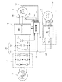
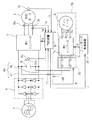
図1は実施の形態1における電力変換装置を例示するブロック図である。当該電力変換装置は直流リンク40に接続される第1インバータ1を備える。制御装置6は第1インバータ1を制御するインバータ制御装置として機能する。
FIG. 1 is a block diagram illustrating a power conversion apparatus according to the first embodiment. The power conversion device includes a
直流リンク40は一対の直流母線、具体的には高電位線41と低電位線42とを有しており、これらには直流電力が供給されて駆動される回転機78と、コンデンサ3と、第1インバータ1の入力側とが並列に接続される。
The DC link 40 has a pair of DC buses, specifically, a high
コンデンサ3は必ずしも平滑機能が要求されず、当該電力変換装置が電解コンデンサレスインバータとして機能できる程度、例えば数十μF程度のフィルムコンデンサやセラミックコンデンサを採用してもよい。
The
回転機78は第2インバータ7とファンモータ8とを有しており、第2インバータ7の入力側は直流リンク40に、その出力側はファンモータ8に、それぞれ接続されている。ファンモータ8は例えば三相の交流回転機であり、ファン(不図示)を駆動する。通常運転時には、直流リンク40から第2インバータ7へ直流電力が供給され、回転機78が駆動される。
The rotating
第2インバータ7は、それぞれ高電位線41と低電位線42に接続される一対の端子7a,7bと、ファンモータ8に交流電圧(ここでは三相交流)を出力する複数の端子7c,7d,7eとを有する。第2インバータ7は、端子7a,7b間に印加される電圧をDC/AC変換して端子7c,7d,7eに出力する。第2インバータ7は電圧形インバータである。
The
第1インバータ1は、高電位線41と低電位線42との間における直流電圧VdcをDC/AC変換して交流電圧を交流モータ2に出力する。通常運転時には、直流リンク40から第1インバータ1へ直流電力が供給され、交流モータ2が駆動される。ここでは交流モータ2は三相の交流モータであり、第1インバータ1は三相交流電力を出力する。
The
交流モータ2は例えば空気調和機の圧縮機(不図示)を機械負荷として駆動する。交流モータ2は誘導機や同期機のどちらであっても下記の本実施の形態の効果が期待できる。
The
整流回路4は、三相交流電源5の交流電圧を直流電圧に変換する。整流回路4は、図1ではダイオードブリッジで構成される場合が例示されるが、ダイオード整流回路に限定されない。整流回路4は、例えばブリッジ整流回路を用いる他励式整流回路、もしくはPWM(Pulse width modulation:パルス幅変調)制御を行うコンバータを用いた自励式整流回路でもよい。本実施の形態は三相交流電源を用いた場合を例にとって説明するが、単相交流電源を用いた場合にも本実施の形態を適用し、同様の効果を得られることは明白である。
The
直流電圧検出器9cは直流電圧Vdcを検出する。速度検出器10は交流モータの回転角速度ωを検出する。これらは公知の技術を用いて実現できる。
The
電流検出器9a,9bは、第1インバータ1と交流モータ2の間に流れるU相電流iu、W相電流iwを検出する。U相電流iu、W相電流iwからV相電流ivを、iu+iv+iw=0の関係から求めることができる。なお、当然ながらW相電流iw及びV相電流ivからU相電流iuを求めてもよい。
電流検出器9a、9bにはカレントトランスを採用することができる。あるいは他の公知の手法を用いて、直流リンク40に流れる電流など第1インバータ1の内部に流れる電流を用いて相電流を検出してもよい。
A current transformer can be adopted for the
電流検出器11は第2インバータ7に入力する電流idfを検出する。但し本実施の形態では第2インバータ7からの回生電流について説明を行うので、電流idfは端子7aから高電位線41に向かう向きを正に採る。つまり電流idfが正のとき、回転機78と直流リンク40との間に流れて直流電圧Vdcを高める電流である。よって以下、電流idfが正のときには、電流idfを流入電流idfと称することがある。
The
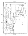
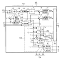
図2は本実施の形態における制御装置6Aの構成を例示するブロック図である。制御装置6Aは図1に示された制御装置6として採用される。制御装置6Aは制御信号生成器38、d軸電流指令生成器101、q軸電流指令生成器102、積分器22、dq変換器23、減算器16,20、d軸電流制御器17、q軸電流制御器21を備えている。
FIG. 2 is a block diagram illustrating the configuration of the
制御信号生成器38は、d軸電圧指令Vd*とq軸電圧指令Vq*とに基づいて、第1インバータ1の動作を制御する制御信号Gを生成する。ここでは例えば第1インバータ1として、一対のスイッチが直列に接続されたレグが、直流リンク40に対して並列に3つ接続された構成を考える。第1インバータ1はスイッチを6個有するので、制御信号Gは6個のスイッチ制御信号を含むことになる。
The
d軸電圧指令Vd*は第1インバータ1が出力する交流電圧のd軸成分の指令値であり、q軸電圧指令Vq*は当該交流電圧のq軸成分の指令値である。ここでd軸とは交流モータ2の界磁軸方向と同相の座標軸であり、q軸とはd軸に対して90度で進相して直交する座標軸である。
The d-axis voltage command Vd * is a command value of the d-axis component of the AC voltage output from the
d軸電流制御器17は、d軸電圧指令Vd*を生成するd軸電圧指令生成器として機能する。q軸電流制御器21は、q軸電圧指令Vq*を生成するq軸電圧指令生成器として機能する。これらの具体的な構成は公知であるので詳細な説明は省略するが、それぞれ後述するd軸電流の偏差及びq軸電流の偏差に基づいて、d軸電圧指令Vd*及びq軸電圧指令Vq*を生成する。
The d-axis
d軸電流の偏差は減算器16によって、d軸電流idを、その指令値たるd軸電流指令id*から減じた値として得られる。ここでd軸電流idとは三相電流iu,iv,iwのd軸成分である。
The deviation of the d-axis current is obtained by the
q軸電流の偏差は減算器20によって、q軸電流iqを、その指令値たるq軸電流指令iq*から減じた値として得られる。ここでq軸電流iqとは三相電流iu,iv,iwのq軸成分である。
The deviation of the q-axis current is obtained by the
d軸電流id及びq軸電流iqは、dq変換器23によってd軸及びq軸で構成される回転座標系に則って、三相電流iu,iv,iwから求められる。実際には上述の様に三相電流の内の一相分は他の二相分から求められるので、図2ではU相電流iuとV相電流ivとが、回転角θと共にdq変換器23に入力する。
The d-axis current id and the q-axis current iq are obtained from the three-phase currents iu, iv and iw by the
回転角θは、速度検出器10から得られた回転角速度ωを積分器22で積分することによって得られる。回転角θを用いたdq変換器23の動作及びその動作を実現するための構成は公知であるので、ここではその説明を省略する。
The rotation angle θ is obtained by integrating the rotation angular velocity ω obtained from the
q軸電流指令生成器102は、減算器18及び速度制御器19を有する。減算器18は回転角速度ωをその指令値たる角速度指令ω*から減じて回転角速度の偏差を得る。速度制御器19は当該偏差及び回転角速度ω並びに電流idfに基づいてq軸電流指令iq*を生成する。電流idfが非正であればq軸電流指令iq*は、回転角速度ωに拘わらず、当該偏差に基づいてq軸電流指令iq*を生成する。このような場合のq軸電流指令iq*の生成は通常の動作であり、公知の技術でもあるので、その詳細な説明は省略する。
The q-axis
他方、本実施の形態で特有の動作として、電流idfが正であり、かつ回転角速度ωが零であれば、q軸電流指令iq*は小さな値を採る。このような回転角速度ωの値及び電流idfの正/非正によるq軸電流指令iq*の生成の切り分けは、公知の技術によって容易に実現できるため、その詳細な説明は省略する。 On the other hand, as an operation peculiar to the present embodiment, if the current idf is positive and the rotational angular velocity ω is zero, the q-axis current command iq * takes a small value. Since the separation of the generation of the q-axis current command iq * based on whether the rotational angular velocity ω and the current idf are positive / non-positive can be easily realized by a known technique, a detailed description thereof is omitted.
電流idfが正である場合とは、回転機78から直流リンク40へと回生電力が与えられる場合である。空気調和機を稼働せず、交流モータ2及びファンモータ8を駆動させない状況で、交流モータ2を回転させないためには、そのトルクを零にすべくq軸電流iqを零にすることが望まれる。よって上述の様に、電流idfが正であれば、q軸電流指令iq*の値を小さくする。
The case where the current idf is positive is a case where regenerative power is applied from the rotating
実際は、例えば以下のように制御する。交流モータ2が駆動されない状況における回転機78からの回生電力を取り扱うのであるから、回転角速度ωが所定の閾値未満である状態で流入電流idf(>0)が発生している場合(「第1の場合」と仮称)において、上記特有の動作を行う。具体的にはこのような場合においてq軸電流指令iq*は、絶対値が所定の閾値未満となる値を採る。これに対して第1の場合以外の場合には、回転角速度の偏差に基づいて、通常通りq軸電流指令iq*を生成する。
Actually, for example, the following control is performed. Since the regenerative power from the rotating
第1の場合におけるq軸電流指令iq*として、所定の閾値未満の固定値を採用することができる。あるいは速度制御器19が採用する偏差として、零から回転角速度ωを差し引いた値を採用してもよい。第1の場合においては角速度指令ω*は実質的には零であり、回転角速度ωも(制御への追従性によっては若干の変動はあるものの)小さな値を採るからである。このような小さな回転角速度ωも、その後の制御によりインバータが出力するトルクが零となるので、このような小さな回転角速度ωも零となる。
As the q-axis current command iq * in the first case, a fixed value less than a predetermined threshold value can be adopted. Alternatively, as the deviation adopted by the
以上のようにしてq軸電流指令生成器102は、交流モータ2が駆動されない状況において回転機78からの回生電力が発生したときに、交流モータ2を回転させない機能を担う。これに対し、d軸電流指令生成器101は、このような回生電力を交流モータ2におおいて消費させる機能を担う。
As described above, the q-axis
d軸電流指令生成器101は、流入電流idfと直流電圧Vdcとに基づいて、d軸電流指令id*を生成する。具体的には、d軸電流指令生成器101は乗算器12、除算器13、平方根演算器14、及びリミッタ15を有している。乗算器12は流入電流idfと直流電圧Vdcとの積を求め、除算器13は当該積を交流モータ2の抵抗成分Rで除した値(商)を求め、平方根演算器14は当該商の平方根を求めてd軸電流原指令id**を求める。
The d-axis
なお、直流リンク40から回転機78に電力が供給されている場合、電流idfが負となる。直流電圧Vdcは正であるので、電流idfが負となれば上記商も負となり、数学的には当該商の平方根を実数として求めることができない。よって電流idfが負の場合(あるいは更に零の場合)には、乗算器12、除算器13,平方根演算器14のいずれかが値零を出力すればよい。
When power is supplied from the DC link 40 to the rotating
リミッタ15はd軸電流原指令id**が所定の上限を超えた場合にd軸電流原指令id**を当該上限値でクリップしたd軸電流指令id*を生成する。これは,回生電力を交流モータ2で消費させる際に、交流モータ2の磁石が減磁したり,巻線を損傷させたりすることがないようにするためである。
When the d-axis current source command id ** exceeds a predetermined upper limit, the
なお、d軸電流idが負になることはないので、d軸電流指令id*も非負の値を採る。上述の様に電流idfが負の場合にはd軸電流原指令id**が零となるので、リミッタ15は下限を設定する必要はない。
Since the d-axis current id does not become negative, the d-axis current command id * also takes a non-negative value. As described above, when the current idf is negative, the d-axis current source command id ** becomes zero, so the
d軸電流指令生成器101が上記の処理を行う理由を以下に説明する。交流モータ2のインダクタンスのd軸成分Ld及びq軸成分Lq、抵抗成分R、第1インバータ1が出力する三相電圧のd軸成分vd及びq軸成分vq、及び交流モータ2の回転トルクTを導入して、式(1)が成立する。
The reason why the d-axis
空気調和機を稼働せず、交流モータ2及びファンモータ8を駆動させない場合、三相交流電源5からの電力供給を無視することにより、インバータから出力する電力、即ち交流モータ2が消費する電力と、回生電力とを一致させることができる。即ち式(2)が成立すればよい。式(2)において左辺はインバータが出力する電力を、右辺は回生電力を、それぞれ示す。
When the air conditioner is not operated and the
式(1),(2)から、式(3)が成り立つ。 From the expressions (1) and (2), the expression (3) is established.
このような状況において交流モータ2を回転させないためには、回転トルクTを零にすべく、上述の様にq軸電流iqを零にするので、式(4)が成り立つ。
In order to prevent the
式(4)の右辺第2項については,瞬時電力としては考慮する必要があるが,ファンモータ8の回生電力を消費するためには,瞬時的でなく時間が長いと考えられる。よって当該第2項を無視して、式(5)が得られる。
The second term on the right side of Equation (4) needs to be considered as instantaneous power, but in order to consume the regenerative power of the
式(5)から式(6)が得られる。よってd軸電流原指令id**として式(6)の右辺を採用すればよい。 Expression (6) is obtained from Expression (5). Therefore, what is necessary is just to employ | adopt the right side of Formula (6) as d-axis current source instruction id **.
よって上述の様にしてd軸電流指令生成器101は、回生電力を交流モータ2の抵抗成分Rにおいて消費させるようにd軸電流指令id*を生成する。また上述の様に、q軸電流指令生成器102は、回転機78からの回生電力が発生したときに交流モータ2を回転させないようにq軸電流指令iq*を生成する。
Therefore, as described above, the d-axis
従って、本実施の形態によれば、回転機78から発生した回生電力を、別の交流モータ2でこれを回転させずに消費し、以て交流モータ2による駆動を避けつつ直流リンク40に設けるコンデンサ3の静電容量を小さくすることができる。このような技術は電解コンデンサレスインバータにも適用可能である。
Therefore, according to the present embodiment, the regenerative electric power generated from the rotating
このような技術により、電力変換器を構成する素子やコンデンサの過電圧破壊を防止できる。また,各部品の耐電圧を上げる必要がないため,コストアップを回避できる。 With such a technique, it is possible to prevent overvoltage breakdown of elements and capacitors constituting the power converter. In addition, since it is not necessary to increase the withstand voltage of each part, an increase in cost can be avoided.
実施の形態2.
図3は本実施の形態における制御装置6Bの構成を例示するブロック図である。制御装置6Bは図1に示された制御装置6として採用される。制御装置6Bは実施の形態1で示された制御装置6Aに対して、周波数設定部103が追加された構成を有している。
FIG. 3 is a block diagram illustrating the configuration of the control device 6B in the present embodiment. The control device 6B is employed as the
周波数設定部103はd軸電流原指令id**を入力し周波数指令fc*を設定する。周波数指令fc*は制御信号生成器38に入力し、制御信号Gの基本周波数として採用される。外部から与えられた周波数指令fc*を基本周波数として制御信号Gを生成する技術それ自体は公知であるので、ここではそれを実現するための制御信号生成器38の具体的な構成の説明を省略する。
The
回転機78からの回生電力と交流モータ2の特性によっては、交流モータ2で回生電力を消費できない可能性もある。よって流入電流idfが大きいほど、第1インバータ1のスイッチング損失を高め、以て回生電力の消費を促進する。
Depending on the regenerative power from the rotating
具体的にはd軸電流原指令id**が大きいほど、周波数指令fc*を高め、第1インバータ1のスイッチング周波数を高める。流入電流idfが大きいほどd軸電流原指令id**が大きく、周波数指令fc*が高いほど制御信号Gの基本周波数が高まるからである。
Specifically, the greater the d-axis current source command id **, the higher the frequency command fc * and the higher the switching frequency of the
図3での例示では、周波数設定部103は、大小判断器27,28、乗算器29,30、切替器31,32を備えている。
In the illustration in FIG. 3, the
大小判断器27は、d軸電流原指令id**と第1閾値it1との大小関係を判断して、切替信号27aを出力する。大小判断器28は、d軸電流原指令id**と第2閾値it2(但しit2>it1)との大小関係を判断して、切替信号28aを出力する。ここではd軸電流原指令id**が第1閾値it1より大きいか否かに応じて、切替信号27aはそれぞれ活性/非活性になる場合を考える。またd軸電流原指令id**が第2閾値it2より大きいか否かに応じて、切替信号28aはそれぞれ活性/非活性になる場合を考える。
The
切替器31は一対の入力端と一つの出力端とを有する。一方の入力端には予め設定された周波数原指令fcが入力する。他方の入力端には周波数2fcが入力する。周波数2fcは、乗算器29が周波数原指令fcと乗数2との積を求めることによって得られる。
The
切替器32は一対の入力端と一つの出力端とを有する。一方の入力端には切替器31の出漁端が接続される。他方の入力端には周波数10fcが入力する。周波数10fcは、乗算器30が周波数2fcと乗数5との積を求めることによって得られる。切替器32の出力端からは周波数指令fc*が出力する。
The
切替器31は切替信号27aによって制御される。具体的には切替器31の出力端には、切替信号27aの非活性/活性によって、それぞれ一方の入力端/他方の入力端が接続される。つまり、d軸電流原指令id**が第1閾値it1より大きい場合には切替器31の出力端から周波数2fcが出力され、d軸電流原指令id**が第1閾値it1以下である場合には切替器31の出力端から周波数原指令fcが出力される。
The
切替器32は切替信号28aによって制御される。具体的には切替器32の出力端には、切替信号28aの非活性/活性によって、それぞれ一方の入力端/他方の入力端が接続される。つまり、d軸電流原指令id**が第2閾値it2より大きい場合には切替器32の出力端から周波数10fcが出力され、d軸電流原指令id**が第2閾値it2以下である場合には切替器31の出力端から得られる周波数が切替器32の出力から出力される。
The
以上の構成から、周波数設定部103は、下記の機能を有することになる:id**≦it1のときfc*=fc;it1<id**≦it2のときfc*=2fc;it2<id**のときfc*=10fc。このようにしてd軸電流原指令id**が大きいほど、周波数指令fc*が高くなり、第1インバータ1のスイッチング周波数を高め、以て第1インバータ1でのスイッチング損失による回生電力の消費を促進する。
From the above configuration, the
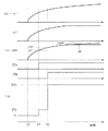
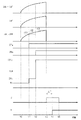
図4は実施の形態2の動作を示すタイミングチャートであり、横軸には時間を採っている。図4は流入電流idf(>0)の他、回生電力Vdc・idf、d軸電流原指令id**及びd軸電流指令id*、切替信号27a,28a、周波数指令fc*を示す。但し切替信号27a,28aはいずれもハイレベルが活性していることを、ローレベルが非活性となっていることを、それぞれ示す。
FIG. 4 is a timing chart showing the operation of the second embodiment, and time is taken on the horizontal axis. FIG. 4 shows regenerative power Vdc · idf, d-axis current source command id **, d-axis current command id *, switching
時点t0は、交流モータ2を駆動させる第1インバータ1が停止中に、逆風でファンが回転して回生電力が発生した時点である。流入電流idfが流れることにより、交流モータ2でファンの回生電力を消費させるべくd軸電流指令id*が増大する。この時点ではまだd軸電流指令id*はd軸電流原指令id**と一致する。
The time point t0 is a point in time when the
しかし,時点t0以降、回生電力が増え続けており、d軸電流指令id*が増加しても回生電力を消費できない可能性がある。よってd軸電流原指令id**が第1閾値it1を超えた時点t1において、周波数指令fc*を周波数原指令fcからその二倍の値2fcに増大させる。 However, since the regenerative power continues to increase after time t0, there is a possibility that the regenerative power cannot be consumed even if the d-axis current command id * increases. Therefore, at time t1 when the d-axis current original command id ** exceeds the first threshold value it1, the frequency command fc * is increased from the frequency original command fc to a value 2fc that is twice that value.
更に回生電力は増え続け、d軸電流原指令id**が第2閾値it2を超えた時点t2において、周波数指令fc*を周波数2fcから周波数10fcに増大させる。その後もd軸電流原指令id**は増加する(図4において破線で示す)が、リミッタ15の機能により、d軸電流指令id*は時間に対して平坦となる波形を示す(図4において実線で示す)。
Further, the regenerative power continues to increase, and at time t2 when the d-axis current source command id ** exceeds the second threshold value it2, the frequency command fc * is increased from the frequency 2fc to the frequency 10fc. Thereafter, the d-axis current command id ** increases (indicated by a broken line in FIG. 4), but due to the function of the
なお、図4において流入電流idfが時間に対して平坦となってからも,回生電力Vdc・idfは増大する。これは直流電圧Vdcの増大に起因する。 In FIG. 4, the regenerative power Vdc · idf increases even after the inflow current idf becomes flat with respect to time. This is due to an increase in the DC voltage Vdc.
このように実施の形態2では実施の形態1と同様の効果が得られる上に、電力変換器を構成する素子やコンデンサの過電圧破壊を防止する効果が高まる。 As described above, in the second embodiment, the same effect as in the first embodiment can be obtained, and the effect of preventing the overvoltage breakdown of the elements and capacitors constituting the power converter is enhanced.
実施の形態3.
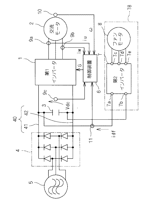
図5は実施の形態3における電力変換装置を例示するブロック図である。当該電力変換装置は実施の形態1において図1で示された構成に対して、接触器33を追加した構成を有している。
FIG. 5 is a block diagram illustrating a power conversion device according to the third embodiment. The power converter has a configuration in which a
具体的には接触器33は、回転機78と直流リンク40との間に設けられる。接触器33が接触状態を採ることにより、端子7aは高電位線41に、端子7bは低電位線42に、それぞれ接続される。この場合、図5に示された構成は,図1に示された構成と等価になる。また接触器33が開放状態を採ることにより、回転機78と直流リンク40との間は遮断される。
Specifically, the
接触器33が開放状態を採るか、接触状態を採るかは、接触器33に入力する制御信号H0で制御される。ここでは制御信号H0の活性/非活性に対応して接触器33がそれぞれ開放状態/接触状態を採る場合を考える。制御信号H0は制御装置6によって生成される。
Whether the
図6は本実施の形態における制御装置6Cの構成を例示するブロック図である。制御装置6Cは図5に示された制御装置6として採用される。制御装置6Cは実施の形態2で示された制御装置6Bに対して、大小判断器35が追加された構成を有している。大小判断器35は、d軸電流原指令id**と第3閾値it3(>it2)との大小関係を判断して、制御信号H0を出力する。大小判断器35は、制御信号H0を生成する制御信号生成器として機能する。
FIG. 6 is a block diagram illustrating the configuration of the control device 6C in the present embodiment. The control device 6C is employed as the
d軸電流原指令id**が第3閾値it3よりも大きい場合には制御信号H0は活性であり、d軸電流原指令id**が第3閾値it3以下であれば制御信号H0は非活性である。但し、制御信号H0は一旦活性化すると、d軸電流原指令id**のその後の値に依らずに活性を維持する。このような制御信号H0は例えばマルチバイブレータを利用することで容易に実現できる。 The control signal H0 is active when the d-axis current source command id ** is larger than the third threshold value it3, and the control signal H0 is inactive when the d-axis current source command id ** is equal to or less than the third threshold value it3. It is. However, once the control signal H0 is activated, it remains active regardless of the subsequent value of the d-axis current source command id **. Such a control signal H0 can be easily realized by using, for example, a multivibrator.
回転機78からの回生電力が大きいほど、交流モータ2や第1インバータ1に流す電流が大きくなるが、これらを構成する素子やコンデンサ3等の過電圧破壊や交流モータ2の減磁を防止することが望ましい。
The larger the regenerative power from the rotating
よって流入電流idfが第2閾値it2を超えて更に第3閾値it3よりも大きくなった場合、制御信号H0を活性化させて接触器33を遮断状態とし、以て回転機78からの回生電力を遮断する。これにより、実施の形態3では実施の形態2の効果が高められる。
Therefore, when the inflow current idf exceeds the second threshold value it2 and further becomes larger than the third threshold value it3, the control signal H0 is activated to turn off the
図7は、実施の形態3の動作を示すタイミングチャートである。実施の形態2の図4と同様、横軸には時間を採り、流入電流idf、回生電力Vdc・idf、d軸電流原指令id**及びd軸電流指令id*、切替信号27a,28a、周波数指令fc*を示す。但し図7では更に、制御信号H0をも示す。但し制御信号H0も切替信号27a,28aと同様、ハイレベルが活性していることを、ローレベルが非活性となっていることを、それぞれ示す。 FIG. 7 is a timing chart showing the operation of the third embodiment. As in FIG. 4 of the second embodiment, the horizontal axis takes time, the inflow current idf, the regenerative power Vdc · idf, the d-axis current source command id **, the d-axis current command id *, the switching signals 27a and 28a, Indicates a frequency command fc *. However, FIG. 7 also shows the control signal H0. However, the control signal H0 also indicates that the high level is active and the low level is inactive, similarly to the switching signals 27a and 28a.
初期的にはd軸電流原指令id**は第3閾値it3よりも小さく、制御信号H0は非活性であり、接触器33は導通状態を採る。よって時点t0,t1,t2において、本実施の形態の動作は実施の形態2の動作と同様であり、説明は繰り返さない。
Initially, the d-axis current source command id ** is smaller than the third threshold value it3, the control signal H0 is inactive, and the
但し時点t2以降、更に流入電流idfが増え続けることにより、交流モータ2でファンの回生電力を消費させるべくd軸電流原指令id**が増大し、時点t3において第3閾値it3を超えた場合が示される。
However, when the inflow current idf continues to increase after time t2, the d-axis current source command id ** increases to consume the regenerative power of the fan in the
これにより制御信号H0は時点t3において活性化し、接触器33が接触状態から開放状態へと遷移し、回転機78は直流リンク40から切り離されるので、流入電流idfは零となる。従って、d軸電流原指令id**、ひいてはd軸電流指令id*も零となり、d軸電流idが過大となることが回避される。
As a result, the control signal H0 is activated at time t3, the contactor 33 changes from the contact state to the open state, and the rotating
なお、このような接触器33の動作に鑑みて、本実施の形態では制御装置6Cからリミッタ15を省略し、d軸電流原指令id**をd軸電流指令id*として採用してもよい。
In view of such an operation of the
実施の形態4.
図8は実施の形態4における電力変換装置を例示するブロック図である。当該電力変換装置は実施の形態4において図5で示された構成に対して、ファンモータ制御装置37を追加した構成を有している。
FIG. 8 is a block diagram illustrating a power conversion device according to the fourth embodiment. The power conversion device has a configuration in which a fan
実施の形態1〜3では第2インバータ7を動作させない状況を説明するために省略されていたが、ファンモータ制御装置37は第2インバータ7のスイッチング動作を制御するスイッチング信号Sを出力するために、通常設けられている要素である。よってその具体的な構成はここでは説明を省略する。
Although the first to third embodiments have been omitted in order to explain the situation where the
但し、本実施の形態においてファンモータ制御装置37は制御装置6から制御信号Jを入力する。そして制御信号Jが活性である場合のスイッチング信号Sは、第2インバータ7にいわゆる零電圧ベクトルによる動作を行わせる。この零電圧ベクトルによる動作それ自体は公知の技術であるが、本実施の形態では、制御信号Jの活性時においてこのような動作が採用される。
However, in the present embodiment, the fan
具体的には、第2インバータ7は電圧形インバータであるので、一対のスイッチが直列に接続されたレグが、端子7a,7b間で並列に3つ接続された構成を備える。そして零電圧ベクトルによる動作では、これらのスイッチを制御することにより、端子7c,7d,7eの全てが端子7a,7bの少なくともいずれか一方に接続される。
Specifically, since the
本実施の形態でも実施の形態3の制御信号H0と同様に、接触器33の動作を制御する制御信号Hを採用する。接触器33は制御信号Hの活性/非活性によってそれぞれ開放状態/接触状態を採る。但し、制御信号Hの活性/非活性は実施の形態3の制御信号H0とは異なる。
In the present embodiment, similarly to the control signal H0 of the third embodiment, the control signal H for controlling the operation of the
図9は本実施の形態における制御装置6Dの構成を例示するブロック図である。制御装置6Dは図8に示された制御装置6として採用される。制御装置6Dは実施の形態3で示された制御装置6Cに対して、遅延器36及びパルス発生器34が追加された構成を有している。
FIG. 9 is a block diagram illustrating the configuration of the control device 6D in the present embodiment. The control device 6D is employed as the
パルス発生器34、大小判断器35、遅延器36は制御信号生成器104を構成し、制御信号H,Jを生成する。具体的には、大小判断器35は実施の形態3で説明されたようにして制御信号H0を生成する。遅延器36は制御信号H0を所定の遅延時間で遅延させて制御信号Hを生成する。パルス発生器34は制御信号H0から制御信号Jを生成する。制御信号Jは、制御信号H0が非活性状態から活性化した時点から、遅延時間よりも長い所定時間において活性化するパルス状の信号である。
The
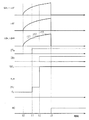
図10は、実施の形態4の動作を示すタイミングチャートである。実施の形態3の図4と同様、横軸には時間を採り、流入電流idf、回生電力Vdc・idf、d軸電流原指令id**及びd軸電流指令id*、切替信号27a,28a、周波数指令fc*を示す。但し図10では更に、制御信号H,Jをも示す。但し制御信号H,Jも切替信号27a,28aと同様、ハイレベルが活性していることを、ローレベルが非活性となっていることを、それぞれ示す。 FIG. 10 is a timing chart showing the operation of the fourth embodiment. Similar to FIG. 4 of the third embodiment, the horizontal axis takes time, the inflow current idf, the regenerative power Vdc · idf, the d-axis current source command id **, the d-axis current command id *, the switching signals 27a and 28a, Indicates a frequency command fc *. However, FIG. 10 also shows control signals H and J. However, the control signals H and J, like the switching signals 27a and 28a, indicate that the high level is active and that the low level is inactive, respectively.
時点t3よりも前の動作は実施の形態3のそれと同じであるので説明を省略する。本実施の形態では時点t3においてd軸電流原指令id**が第3閾値it3を超えると、制御信号Jが活性化し、第2インバータ7の端子7c,7d,7eを全て短絡させる。これにより、ファンモータ8の回転による電流はファンモータ8内を環流することになる。これにより、流入電流idfは零となり、回生電力Vdc・idf及びd軸電流原指令id**も零となる。但しこの時点では制御信号Hは非活性のままであり、接触器33は接触状態を保ったまま、流入電流idfは零となる。よって実施の形態3の効果が得られる。
Since the operation before time t3 is the same as that of the third embodiment, the description thereof is omitted. In the present embodiment, when the d-axis current source command id ** exceeds the third threshold value it3 at time t3, the control signal J is activated and all the
そして時点t3から遅延時間ΔTが経過した時点t4において制御信号Hが活性化し、接触器33は開放状態に移行する。このように、接触器33が接触状態から開放状態へと遷移する際に、接触器33に電流が流れていないことは、接触器33のコストを低減する観点で望ましい。接触器33に電流が流れていない場合の方が、流れている場合と比較して、これを接触状態から開放状態へと遷移させるために必要な仕事量が小さくて済むからである。
At time t4 when the delay time ΔT has elapsed from time t3, the control signal H is activated, and the
時点t4の後、時点t5において制御信号Jは非活性となり、第2インバータ7において端子7c,7d,7e同士の短絡は解除される。これによりファンモータ8では電流が環流せず、その損傷が回避される。また時点t5においても接触器33は開放状態にあるので、流入電流idfは流れない。
After time t4, the control signal J is deactivated at time t5, and the short circuit between the
このように本実施の形態では、実施の形態3の効果に加え、安価な接触器33を採用できるという効果がある。
Thus, in this embodiment, in addition to the effect of the third embodiment, there is an effect that an
なお、実施の形態3と同様に、接触器33の動作に鑑みて、本実施の形態でも制御装置6Cからリミッタ15を省略し、d軸電流原指令id**をd軸電流指令id*として採用してもよい。
As in the third embodiment, in view of the operation of the
1 第1インバータ
2 交流モータ
6,6A,6B,6C,6D 制御装置
7 第2インバータ
7a,7b,7c,7d,7e 端子
8 ファンモータ
17 d軸電流制御器
18 減算器
19 速度制御器
21 q軸電流制御器
33 接触器
35 大小判断器
38 制御信号生成器
41 高電位線
42 低電位線
78 回転機
101 d軸電流指令生成器
102 q軸電流指令生成器
103 周波数設定部
104 制御信号生成器
DESCRIPTION OF
Claims (11)
前記交流モータの界磁軸方向と同相のd軸における前記第1交流電圧の成分の指令値たるd軸電圧指令(Vd*)と、前記第1交流電圧の前記界磁軸方向に対して直交するq軸における前記第1交流電圧の成分の指令値たるq軸電圧指令(Vq*)とに基づいて、前記第1インバータの動作を制御する第1制御信号(G)を生成する第1制御信号生成器(38)と、
前記d軸における前記第1インバータが出力する電流の成分(id)の、その指令値たるd軸電流指令(id*)に対する偏差に基づいて、前記d軸電圧指令(Vd*)を生成するd軸電圧指令生成器(17)と、
前記回転機と前記一対の直流母線との間に流れて前記直流電圧を高める電流たる流入電流(idf)と前記直流電圧との積を前記交流モータの抵抗成分(R)で除した値の平方根である第1値(id**)に基づいて、前記d軸電流指令を生成するd軸電流指令生成器(101)と、
前記q軸における前記第1インバータが出力する電流の成分(iq)の、その指令値たるq軸電流指令(iq*)に対する偏差に基づいて前記q軸電圧指令(Vq*)を生成するq軸電圧指令生成器(21)と、
前記交流モータの回転角速度(ω)が第1閾値未満である状態で前記流入電流が発生した第1の場合には絶対値が第2閾値未満である値を前記q軸電流指令として生成し、それ以外の場合には前記回転角速度の、その指令値たる角速度指令(ω*)に対する偏差に基づいて前記q軸電流指令を生成するq軸電流指令生成器(102)と
を備えるインバータ制御装置。 A DC motor is connected to a pair of DC buses (41, 42) together with a rotating machine (78) driven by DC power, and a DC voltage (Vdc) between the pair of DC buses is DC / AC converted to generate a first AC. A control device (6A, 6B, 6C, 6D) for controlling a first inverter (1) that outputs a voltage to an AC motor (2),
The d-axis voltage command (Vd *), which is the command value of the component of the first AC voltage on the d-axis in phase with the field axis direction of the AC motor, is orthogonal to the field axis direction of the first AC voltage. First control for generating a first control signal (G) for controlling the operation of the first inverter based on a q-axis voltage command (Vq *) which is a command value of the first AC voltage component on the q-axis. A signal generator (38);
The d-axis voltage command (Vd *) is generated based on the deviation of the current component (id) output from the first inverter in the d-axis with respect to the d-axis current command (id *) as the command value. A shaft voltage command generator (17);
The square root of a value obtained by dividing the product of the inflow current (idf), which is a current flowing between the rotating machine and the pair of DC buses, and increasing the DC voltage, and the DC voltage by the resistance component (R) of the AC motor. A d-axis current command generator (101) that generates the d-axis current command based on the first value (id **),
The q-axis that generates the q-axis voltage command (Vq *) based on the deviation of the current component (iq) output from the first inverter in the q-axis with respect to the q-axis current command (iq *) that is the command value A voltage command generator (21);
In the first case where the inflow current is generated in a state where the rotational angular velocity (ω) of the AC motor is less than a first threshold, a value whose absolute value is less than a second threshold is generated as the q-axis current command. In other cases, an inverter control device comprising a q-axis current command generator (102) that generates the q-axis current command based on a deviation of the rotational angular velocity from an angular velocity command (ω *) that is a command value thereof.
前記回転角速度(ω)の前記角速度指令(ω*)に対する前記偏差を求める減算器(18)と、
前記偏差に基づいて前記q軸電流指令(iq*)を求める速度制御器(19)と
を有し、
前記第1の場合には、零から前記回転角速度を減じた値を前記偏差として採用する、請求項1記載のインバータ制御装置(6A,6B,6C,6D)。 The q-axis current command generator (102)
A subtractor (18) for determining the deviation of the rotational angular velocity (ω) from the angular velocity command (ω *);
A speed controller (19) for obtaining the q-axis current command (iq *) based on the deviation,
The inverter control device (6A, 6B, 6C, 6D) according to claim 1, wherein, in the first case, a value obtained by subtracting the rotational angular velocity from zero is adopted as the deviation.
を更に備える、請求項1または請求項2記載のインバータ制御装置(6B,6C,6D)。 A frequency setting unit (103) that sets a frequency having a higher value as the first value (id **) is larger as a fundamental frequency (fc *) of the first control signal.
The inverter control device (6B, 6C, 6D) according to claim 1 or 2, further comprising:
前記第1値(id**)が第3閾値を超えれば前記接触器を開放させる第2制御信号(H0)を生成する第2制御信号生成器(35)
を更に備える、請求項1から請求項3のいずれか一つに記載のインバータ制御装置(6C,6D)。 A contactor (33) is provided between the rotating machine (78) and the pair of DC buses (41, 42),
A second control signal generator (35) for generating a second control signal (H0) for opening the contactor when the first value (id **) exceeds a third threshold.
The inverter control device (6C, 6D) according to any one of claims 1 to 3, further comprising:
前記回転機は、
交流回転機(8)と、
前記一対の直流母線(41,42)に接続される一対の第1端子(7a,7b)と、前記一対の第1端子間に印加される電圧をDC/AC変換して前記交流回転機に第2交流電圧を出力する複数の第2端子(7c,7d,7e)とを有する、電圧形インバータである第2インバータ(7)
を有し、
前記第1値(id**)が第3閾値を超えた第1時点(t3)から所定期間(ΔT)が経過した第2時点(t4)において前記接触器を開放させる第2制御信号(H)と、前記第1時点から前記所定期間よりも長い期間において、前記第2インバータに前記複数の第2端子を全て短絡させる第3制御信号(J)とを生成する第2制御信号生成器(104)
を更に備える、請求項1から請求項3のいずれか一つに記載のインバータ制御装置(6D)。 A contactor (33) is provided between the rotating machine (78) and the pair of DC buses (41, 42),
The rotating machine is
AC rotating machine (8),
A pair of first terminals (7a, 7b) connected to the pair of DC buses (41, 42) and a voltage applied between the pair of first terminals are DC / AC converted into the AC rotating machine. A second inverter (7), which is a voltage source inverter, having a plurality of second terminals (7c, 7d, 7e) for outputting a second AC voltage.
Have
A second control signal (H) that opens the contactor at a second time point (t4) when a predetermined period (ΔT) has elapsed from a first time point (t3) when the first value (id **) exceeds a third threshold value. ) And a third control signal generator (J) that causes the second inverter to short-circuit all of the plurality of second terminals in a period longer than the predetermined period from the first time point ( 104)
The inverter control device (6D) according to any one of claims 1 to 3, further comprising:
前記回転機と前記一対の直流母線との間に流れて前記直流電圧を高める電流たる流入電流(idf)と前記直流電圧との積たる回生電力を前記交流モータに消費させ、
前記回生電力の消費によっても前記交流モータが回転しないように前記第1交流電圧を前記第1インバータに出力させる、インバータの制御方法。 A DC motor is connected to a pair of DC buses (41, 42) together with a rotating machine (78) driven by DC power, and a DC voltage (Vdc) between the pair of DC buses is DC / AC converted to generate a first AC. A method for controlling a first inverter (1) that outputs a voltage to an AC motor (2), comprising:
Causing the AC motor to consume regenerative power, which is a product of the DC voltage and an inflow current (idf) that flows between the rotating machine and the pair of DC buses to increase the DC voltage,
An inverter control method for causing the first inverter to output the first AC voltage so that the AC motor does not rotate even when the regenerative power is consumed.
前記第1インバータが出力する電流の前記交流モータの前記界磁軸方向に対して直交するq軸における成分(iq)の指令値たるq電流指令(iq*)を、前記交流モータの回転角速度(ω)が第1閾値未満である状態で前記流入電流が発生した第1の場合には絶対値が第2閾値未満である値で生成し、それ以外の場合には前記回転角速度の、その指令値たる角速度指令(ω*)に対する偏差に基づいて生成する、請求項6記載のインバータの制御方法。 The d-axis current command (id *), which is the command value of the component (id) in the d-axis in phase with the field axis direction of the AC motor, of the current output from the first inverter, the regenerative power as the resistance of the AC motor Based on the first value (id **) that is the square root of the value divided by the component (R),
The q current command (iq *), which is the command value of the component (iq) in the q axis orthogonal to the field axis direction of the AC motor, of the current output from the first inverter is set as the rotational angular velocity ( In the first case where the inflow current is generated in a state where ω) is less than the first threshold value, the absolute value is generated with a value less than the second threshold value. In other cases, the rotation angular velocity command is generated. The inverter control method according to claim 6, wherein the inverter is generated based on a deviation with respect to the angular velocity command (ω *).
前記第1値(id**)が第3閾値を超えれば前記接触器を開放させる、請求項7から請求項9のいずれか一つに記載のインバータの制御方法。 A contactor (33) is provided between the rotating machine (78) and the pair of DC buses (41, 42),
The method for controlling an inverter according to any one of claims 7 to 9, wherein the contactor is opened if the first value (id **) exceeds a third threshold value.
前記回転機は、
交流回転機(8)と、
前記一対の直流母線(41,42)に接続される一対の第1端子(7a,7b)と、前記一対の第1端子間に印加される電圧をDC/AC変換して前記交流回転機に第2交流電圧を出力する複数の第2端子(7c,7d,7e)とを有する、電圧形インバータである第2インバータ(7)
を有し、
前記第1値(id**)が第3閾値を超えた第1時点(t3)から所定期間(ΔT)が経過した第2時点(t4)において前記接触器を開放させ、前記第1時点から前記所定期間よりも長い期間において、前記第2インバータに前記複数の第2端子を全て短絡させる、請求項7から請求項9のいずれか一つに記載のインバータの制御方法。 A contactor (33) is provided between the rotating machine (78) and the pair of DC buses (41, 42),
The rotating machine is
AC rotating machine (8),
A pair of first terminals (7a, 7b) connected to the pair of DC buses (41, 42) and a voltage applied between the pair of first terminals are DC / AC converted into the AC rotating machine. A second inverter (7), which is a voltage source inverter, having a plurality of second terminals (7c, 7d, 7e) for outputting a second AC voltage.
Have
The contactor is opened at a second time point (t4) when a predetermined period (ΔT) has elapsed from a first time point (t3) when the first value (id **) exceeds a third threshold, and from the first time point The inverter control method according to claim 7, wherein the plurality of second terminals are all short-circuited to the second inverter in a period longer than the predetermined period.
Priority Applications (1)
| Application Number | Priority Date | Filing Date | Title |
|---|---|---|---|
| JP2016000944A JP2017123718A (en) | 2016-01-06 | 2016-01-06 | Inverter control device, and method of controlling inverter |
Applications Claiming Priority (1)
| Application Number | Priority Date | Filing Date | Title |
|---|---|---|---|
| JP2016000944A JP2017123718A (en) | 2016-01-06 | 2016-01-06 | Inverter control device, and method of controlling inverter |
Publications (1)
| Publication Number | Publication Date |
|---|---|
| JP2017123718A true JP2017123718A (en) | 2017-07-13 |
Family
ID=59306764
Family Applications (1)
| Application Number | Title | Priority Date | Filing Date |
|---|---|---|---|
| JP2016000944A Pending JP2017123718A (en) | 2016-01-06 | 2016-01-06 | Inverter control device, and method of controlling inverter |
Country Status (1)
| Country | Link |
|---|---|
| JP (1) | JP2017123718A (en) |
-
2016
- 2016-01-06 JP JP2016000944A patent/JP2017123718A/en active Pending
Similar Documents
| Publication | Publication Date | Title |
|---|---|---|
| CN103973200B (en) | DC-to-AC converter and electric motor drive system | |
| JP6067105B2 (en) | Power conversion apparatus, motor drive apparatus including the same, blower including the same, compressor, air conditioner including them, refrigerator, and refrigerator | |
| JP4433099B1 (en) | Power converter | |
| EP3528383B1 (en) | Control device and control method for alternating current motor | |
| JP5862125B2 (en) | Control device for power converter | |
| JP5733326B2 (en) | Current source inverter device | |
| JP5549751B1 (en) | Inverter device, control method for inverter device, and motor drive system | |
| JP5813934B2 (en) | Power converter | |
| JP6704466B2 (en) | Electric motor drive | |
| KR101514391B1 (en) | Vector controller and motor controller using the same, air-conditioner | |
| CN103368477B (en) | The drive unit of synchronous motor and use the air-supply arrangement of this drive unit | |
| EP3160036B1 (en) | Power conversion apparatus | |
| CN109983689B (en) | Inverter control device and motor drive system | |
| US20150097505A1 (en) | Current source inverter device | |
| JP2020043719A (en) | Motor control device and motor control method | |
| WO2020174621A1 (en) | Motor drive device and air conditioner | |
| JP2018057131A (en) | Flywheel power storage system | |
| EP2757682A2 (en) | Motor control apparatus and motor control method | |
| JP2017188968A (en) | Motor drive device | |
| JP4591049B2 (en) | AC / AC direct converter motor controller | |
| JP2017123718A (en) | Inverter control device, and method of controlling inverter | |
| JP2007082321A (en) | Electric motor drive | |
| WO2015087437A1 (en) | Power conversion device | |
| JP6450507B2 (en) | Electric brake unit | |
| TW202604123A (en) | Power control devices, power control methods, and air conditioners |