JP2017122501A - Shaft connection structure of vehicle - Google Patents

Shaft connection structure of vehicle Download PDF

Info

Publication number
JP2017122501A
JP2017122501A JP2016003054A JP2016003054A JP2017122501A JP 2017122501 A JP2017122501 A JP 2017122501A JP 2016003054 A JP2016003054 A JP 2016003054A JP 2016003054 A JP2016003054 A JP 2016003054A JP 2017122501 A JP2017122501 A JP 2017122501A
Authority
JP
Japan
Prior art keywords
shaft
tolerance ring
central axis
base portion
reduction
Prior art date
Legal status (The legal status is an assumption and is not a legal conclusion. Google has not performed a legal analysis and makes no representation as to the accuracy of the status listed.)
Pending
Application number
JP2016003054A
Other languages
Japanese (ja)
Inventor
靖浩 斎藤
Yasuhiro Saito
靖浩 斎藤
裕輔 武島
Yusuke Takeshima
裕輔 武島
Current Assignee (The listed assignees may be inaccurate. Google has not performed a legal analysis and makes no representation or warranty as to the accuracy of the list.)
Toyota Motor Corp
Original Assignee
Toyota Motor Corp
Priority date (The priority date is an assumption and is not a legal conclusion. Google has not performed a legal analysis and makes no representation as to the accuracy of the date listed.)
Filing date
Publication date
Application filed by Toyota Motor Corp filed Critical Toyota Motor Corp
Priority to JP2016003054A priority Critical patent/JP2017122501A/en
Publication of JP2017122501A publication Critical patent/JP2017122501A/en
Pending legal-status Critical Current

Links

Images

Classifications

    • FMECHANICAL ENGINEERING; LIGHTING; HEATING; WEAPONS; BLASTING
    • F16ENGINEERING ELEMENTS AND UNITS; GENERAL MEASURES FOR PRODUCING AND MAINTAINING EFFECTIVE FUNCTIONING OF MACHINES OR INSTALLATIONS; THERMAL INSULATION IN GENERAL
    • F16DCOUPLINGS FOR TRANSMITTING ROTATION; CLUTCHES; BRAKES
    • F16D1/00Couplings for rigidly connecting two coaxial shafts or other movable machine elements
    • F16D1/06Couplings for rigidly connecting two coaxial shafts or other movable machine elements for attachment of a member on a shaft or on a shaft-end
    • F16D1/08Couplings for rigidly connecting two coaxial shafts or other movable machine elements for attachment of a member on a shaft or on a shaft-end with clamping hub; with hub and longitudinal key
    • F16D1/0829Couplings for rigidly connecting two coaxial shafts or other movable machine elements for attachment of a member on a shaft or on a shaft-end with clamping hub; with hub and longitudinal key with radial loading of both hub and shaft by an intermediate ring or sleeve
    • F16D1/0835Couplings for rigidly connecting two coaxial shafts or other movable machine elements for attachment of a member on a shaft or on a shaft-end with clamping hub; with hub and longitudinal key with radial loading of both hub and shaft by an intermediate ring or sleeve due to the elasticity of the ring or sleeve

Abstract

PROBLEM TO BE SOLVED: To suppress a stress concentration to a salient part of a tolerance ring by a load in a radial direction caused by relative inclinations of an outside shaft and an inside shaft in the radial direction.SOLUTION: In a shaft connection structure 10 of a vehicle, a tolerance ring 34 comprises a ring-shaped base part 42, and a salient part 44 which is salient to a radial direction from a plurality of regions which are separated to a peripheral direction of the base part 42, and extends to a center axial line C direction. The base part 42 and the salient part 44 are curvedly formed so as to become large in diameters as progressing toward centers compared with both ends in the center axial core C direction, an annular salient part 50 having a salient curved face 52 continuous to the peripheral direction is formed at a position in which the base part 42 of a reduction shaft 18 is arranged, and the tolerance ring 34 is arranged outside the reduction shaft 18 so that the base part 42 slide-contacts with the annular salient part 50. Therefore, a stress concentration to the salient part 44 caused by relative inclinations of the reduction shaft 18 and a rotor shaft 14 is suppressed.SELECTED DRAWING: Figure 3

Description

本発明は、車両のシャフト連結構造に関し、とりわけ、外側シャフトと内側シャフトとの相対的な径方向の傾きによるトレランスリングの凸部への径方向の荷重による応力集中を抑制する技術に関する。   The present invention relates to a vehicle shaft connection structure, and more particularly to a technique for suppressing stress concentration due to a radial load on a convex portion of a tolerance ring due to a relative radial inclination between an outer shaft and an inner shaft.

内側シャフトと、前記内側シャフトと同軸に、前記内側シャフトより外側に配置された外側シャフトと、前記内側シャフトの外周面と前記外側シャフトの内周面との間に圧入されたトレランスリングと、を含む車両のシャフト連結構造が知られている。たとえば、特許文献1の車両のシャフト連結構造がそれである。トレランスリングは、内側シャフトの外周面と外側シャフトの内周面との間に摩擦力を発生させることにより、内側シャフトと外側シャフトとの間の連結機構のガタツキが阻止される。たとえば内側シャフトと外側シャフトとがスプライン嵌合部により動力伝達可能に連結され、そのスプライン嵌合部の軸方向の隣りにトレランスリングが配置される場合に、駆動源からのトルク変動が伝達されることに起因したスプライン嵌合部での歯打ち音の発生がトレランスリングにより抑制される。   An inner shaft, an outer shaft arranged coaxially with the inner shaft and outside the inner shaft, and a tolerance ring press-fitted between the outer peripheral surface of the inner shaft and the inner peripheral surface of the outer shaft. Including a vehicle shaft connection structure is known. For example, this is the vehicle shaft coupling structure of Patent Document 1. The tolerance ring generates frictional force between the outer peripheral surface of the inner shaft and the inner peripheral surface of the outer shaft, thereby preventing rattling of the coupling mechanism between the inner shaft and the outer shaft. For example, when an inner shaft and an outer shaft are connected by a spline fitting portion so that power can be transmitted, and a tolerance ring is arranged adjacent to the spline fitting portion in the axial direction, torque fluctuations from the drive source are transmitted. The occurrence of rattling noise at the spline fitting portion due to this is suppressed by the tolerance ring.

特開2015−39944号公報JP2015-39944A

ところで、外側シャフトと内側シャフトとが径方向に相対的に傾きながら回転することが考えられる。図4は、内側シャフト112の外周面と外側シャフト114の内周面と間にトレランスリング116が配置されたシャフト連結構造110であって、内側シャフト112と外側シャフト114とが回転している状態の一例を模式的に示す断面図である。なお、内側シャフト112の中心軸線Cが一点鎖線で示され、内側シャフト112の一部および、外側シャフト114とトレランスリング116の内側シャフト112の中心軸線Cから下半分は省略されている。トレランスリング116は、リング状のベース部118と、ベース部118から径方向の外側へ突出した中心軸線C方向へ延びる複数の凸部120とを一体に備えている。凸部120はベース部118に周方向において等間隔に形成されている。たとえば、図示しない歯車の噛み合いによって外側シャフト114と内側シャフト112とは、内側シャフト112の外側シャフト114に対しての径方向の傾きの大きさが変化する相対的な振動が加えられながら回転するため、トレランスリング116の外側シャフト114の内周面と当接する凸部120の中心軸線C方向の一端には径方向の荷重による応力が集中して、トレランスリング116が局所的に塑性変形し、その性能が低下する可能性があった。   By the way, it is conceivable that the outer shaft and the inner shaft rotate while being relatively inclined in the radial direction. FIG. 4 shows a shaft coupling structure 110 in which a tolerance ring 116 is disposed between the outer peripheral surface of the inner shaft 112 and the inner peripheral surface of the outer shaft 114, and the inner shaft 112 and the outer shaft 114 are rotating. It is sectional drawing which shows an example typically. The central axis C of the inner shaft 112 is indicated by a one-dot chain line, and a part of the inner shaft 112 and the lower half from the central axis C of the inner shaft 112 of the outer shaft 114 and the tolerance ring 116 are omitted. The tolerance ring 116 is integrally provided with a ring-shaped base portion 118 and a plurality of convex portions 120 extending from the base portion 118 in the central axis C direction and projecting radially outward. The convex portions 120 are formed on the base portion 118 at equal intervals in the circumferential direction. For example, the outer shaft 114 and the inner shaft 112 rotate while being applied with a relative vibration that changes the magnitude of the radial inclination of the inner shaft 112 with respect to the outer shaft 114 due to meshing of gears (not shown). The stress due to the radial load is concentrated on one end of the convex portion 120 in contact with the inner peripheral surface of the outer shaft 114 of the tolerance ring 116 in the central axis C direction, and the tolerance ring 116 is locally plastically deformed. Performance could be degraded.

本発明は、以上の事情を背景として為されたものであり、その目的とするところは、外側シャフトと内側シャフトとの相対的な径方向の傾きによるトレランスリングの凸部への径方向の荷重による応力集中およびそれによる塑性変形を抑制することにある。   The present invention has been made against the background of the above circumstances, and its purpose is to apply a radial load to the convex portion of the tolerance ring due to a relative radial inclination between the outer shaft and the inner shaft. This is to suppress the stress concentration due to the stress and the plastic deformation caused thereby.

第1発明の要旨とするところは、内側シャフトと、前記内側シャフトと同軸に、前記内側シャフトより外側に配置された外側シャフトと、前記内側シャフトの外周面と前記外側シャフトの内周面との間に圧入されたトレランスリングとを、含む車両のシャフト連結構造であって、前記トレランスリングは、リング状のベース部と、前記ベース部の周方向に離隔した複数部位から外周側に突出し且つ前記内側シャフトの中心軸線方向に延びる長手状の凸部とを備え、前記ベース部および前記凸部は、前記中心軸線方向における両端に比べ中央ほど前記中心軸線を中心とする径が大きくなるように曲成され、前記凸部は、前記ベース部からの突出量および周方向の幅寸法が前記中心軸線方向の中央ほど大きく形成され、前記内側シャフトの前記トレランスリングの前記ベース部が配置される位置には、前記内側シャフトの周方向に連なる凸曲面を有する環状凸部が形成され、前記トレランスリングは、前記環状凸部が前記トレランスリングの前記ベース部の内周面と摺接するように、前記内側シャフトの外側に配置されることにある。   The gist of the first invention is that an inner shaft, an outer shaft arranged coaxially with the inner shaft and outside the inner shaft, an outer peripheral surface of the inner shaft and an inner peripheral surface of the outer shaft. A vehicle shaft connection structure including a tolerance ring press-fitted between, wherein the tolerance ring protrudes outward from a ring-shaped base portion and a plurality of portions spaced in the circumferential direction of the base portion, and A longitudinal convex portion extending in the direction of the central axis of the inner shaft, and the base portion and the convex portion are curved so that a diameter centered on the central axis is larger toward the center than both ends in the central axis direction. The protrusion is formed such that the amount of protrusion from the base portion and the width in the circumferential direction are larger toward the center in the central axis direction, and the protrusion of the inner shaft is formed. An annular convex portion having a convex curved surface continuous in the circumferential direction of the inner shaft is formed at a position where the base portion of the lance ring is disposed, and the annular convex portion is the base portion of the tolerance ring. It exists in arrange | positioning on the outer side of the said inner side shaft so that a sliding contact may be carried out.

第2発明の要旨とするところは、前記内側シャフトに形成された環状凸部の凸曲面は、前記トレランスリングの前記ベース部の幅寸法より大きい幅寸法を有していることにある。   The gist of the second invention is that the convex curved surface of the annular convex portion formed on the inner shaft has a width dimension larger than the width dimension of the base portion of the tolerance ring.

第1発明によれば、前記トレランスリングは、リング状のベース部と、前記ベース部の周方向に離隔した複数部位から外周側に突出し且つ前記内側シャフトの中心軸線方向に延びる長手状の凸部とを備え、前記ベース部および前記凸部は、前記中心軸線方向における両端に比べ中央ほど前記中心軸線を中心とする径が大きくなるように曲成され、前記凸部は、前記ベース部からの突出量および周方向の幅寸法が前記中心軸線方向の中央ほど大きく形成され、前記内側シャフトの前記トレランスリングの前記ベース部が配置される位置には、前記内側シャフトの周方向に連なる凸曲面を有する環状凸部が形成され、前記トレランスリングは、前記環状凸部が前記トレランスリングの前記ベース部の内周面と摺接するように、前記内側シャフトの外側に配置される。このため、内側シャフトと外側シャフトとの径方向の相対的な傾きの大きさが変化する範囲において、トレランスリングは、中心軸線方向における両端に比べ中央ほどベース部からの突出量が大きくなるように曲成された凸部の外周面で外側シャフトの内周面と当接させられ、ベース部の内周面が環状凸部の凸曲面に摺接させられる。これにより、外側シャフトと内側シャフトとが径方向に相対的に傾きながら回転する際のトレランスリングの凸部への径方向の荷重による応力集中およびそれによる塑性変形が抑制される。   According to the first aspect of the present invention, the tolerance ring includes a ring-shaped base portion, and a long convex portion that protrudes toward the outer peripheral side from a plurality of portions spaced in the circumferential direction of the base portion and extends in the central axis direction of the inner shaft. The base portion and the convex portion are bent so that the diameter centered on the central axis becomes larger toward the center than the both ends in the central axis direction, and the convex portion extends from the base portion. A protruding amount and a width in the circumferential direction are formed so as to increase toward the center in the central axis direction, and a convex curved surface continuous in the circumferential direction of the inner shaft is provided at a position where the base portion of the tolerance ring of the inner shaft is disposed. The tolerance ring is formed so that the annular projection is in sliding contact with the inner peripheral surface of the base portion of the tolerance ring. It is arranged on the side. For this reason, within the range in which the relative inclination of the inner shaft and the outer shaft changes in the radial direction, the tolerance ring has a greater amount of protrusion from the base portion at the center than at both ends in the central axis direction. The outer peripheral surface of the bent convex portion is brought into contact with the inner peripheral surface of the outer shaft, and the inner peripheral surface of the base portion is brought into sliding contact with the convex curved surface of the annular convex portion. This suppresses stress concentration due to a radial load on the convex portion of the tolerance ring and plastic deformation caused by the rotation when the outer shaft and the inner shaft rotate while being relatively inclined in the radial direction.

第2発明によれば、前記内側シャフトに形成された環状凸部の凸曲面は、前記トレランスリングの前記ベース部の幅寸法より大きい幅寸法を有しているので、トレランスリングが内側シャフト又は外側シャフトからスラスト方向の脈動荷重を受けたとき、トレランスリングのベース部の内周面とそれに摺接する環状凸部の凸曲面との間の摺動によって上記スラスト方向の脈動荷重が吸収される利点がある。   According to the second invention, the convex curved surface of the annular convex portion formed on the inner shaft has a width dimension larger than the width dimension of the base portion of the tolerance ring. When receiving a pulsating load in the thrust direction from the shaft, there is an advantage that the pulsating load in the thrust direction is absorbed by sliding between the inner peripheral surface of the base portion of the tolerance ring and the convex curved surface of the annular convex portion slidably in contact therewith. is there.

本発明の車両のシャフト連結構造が適用された動力伝達装置の要部の断面を拡大して示す図である。It is a figure which expands and shows the cross section of the principal part of the power transmission device to which the shaft connection structure of the vehicle of this invention was applied. 図1の車両のシャフト連結構造に備えられるトレランスリングを中心軸線方向に視た図であって、その一部が中心軸線方向の中央部において切り欠かれている。It is the figure which looked at the tolerance ring with which the shaft connection structure of the vehicle of FIG. 1 is provided in the central axis direction, Comprising: The part is notched in the center part of the central axis direction. 図1の車両のシャフト連結構造のトレランスリング周辺の要部を模式的に示す図であり、カウンタドリブンギヤとリダクションギヤとのギヤ噛合い反力によりリダクション軸とロータ軸とが径方向に相対的に傾いた状態で回転している状態が示されている。FIG. 2 is a diagram schematically showing a main part around a tolerance ring of the shaft connection structure of the vehicle in FIG. 1, in which the reduction shaft and the rotor shaft are relatively moved in the radial direction by the gear meshing reaction force between the counter driven gear and the reduction gear. A state of being rotated in a tilted state is shown. 内側シャフトの外周面と外側シャフトの内周面と間にトレランスリングが配置されたシャフト連結構造であって、内側シャフトと外側シャフトとが径方向に相対的に傾きながら回転する状態の一例を模式的に示す図である。A shaft coupling structure in which a tolerance ring is arranged between the outer peripheral surface of the inner shaft and the inner peripheral surface of the outer shaft, and an example of a state in which the inner shaft and the outer shaft rotate while being relatively inclined in the radial direction FIG.

以下、本発明の車両のシャフト連結構造の一実施例について図面を参照して詳細に説明する。   Hereinafter, an embodiment of a vehicle shaft connection structure of the present invention will be described in detail with reference to the drawings.

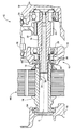
図1は、車両のシャフト連結構造10が適用された動力伝達装置12の要部の断面を拡大して示す図である。動力伝達装置12の中心軸線C上において、電動機MGのロータ軸14がスプライン嵌合部16を介してリダクション軸18に接続されている。リダクション軸18には、斜歯で構成されるリダクションギヤ20が形成され、図示しないカウンタ軸に形成されているカウンタドリブンギヤ22と噛み合っており、リダクションギヤ20およびカウンタドリブンギヤ22によって構成されるギヤ対(斜歯歯車)を介してリダクション軸18とカウンタ軸とが動力伝達可能に接続される。電動機MGのロータ軸14は、中心軸線C方向の両端が玉軸受24および玉軸受26によって中心軸線Cまわりに回転可能にケース19に支持されている。また、リダクション軸18は、中心軸線C方向の両端が玉軸受28および玉軸受30によって中心軸線Cまわりに回転可能にケース19に支持されている。   FIG. 1 is an enlarged view showing a cross section of a main part of a power transmission device 12 to which a vehicle shaft coupling structure 10 is applied. On the central axis C of the power transmission device 12, the rotor shaft 14 of the electric motor MG is connected to the reduction shaft 18 via the spline fitting portion 16. The reduction shaft 18 is formed with a reduction gear 20 composed of inclined teeth, meshed with a counter driven gear 22 formed on a counter shaft (not shown), and a gear pair composed of the reduction gear 20 and the counter driven gear 22 ( The reduction shaft 18 and the counter shaft are connected via a bevel gear) so as to be able to transmit power. The rotor shaft 14 of the electric motor MG is supported by the case 19 so that both ends in the direction of the central axis C can rotate around the central axis C by ball bearings 24 and 26. The reduction shaft 18 is supported by the case 19 so that both ends in the direction of the central axis C can be rotated around the central axis C by ball bearings 28 and ball bearings 30.

カウンタ軸には、図示しないカウンタドライブギヤおよびリダクションギヤ20と噛み合うカウンタドリブンギヤ22と、図示しないデフギヤに形成されているデフリングギヤと噛み合うデフドライブギヤ32とが一体的に形成されている。カウンタドライブギヤには、図示しない動力分配機構を介してエンジンからの動力が伝達される。このように、カウンタドリブンギヤ22がカウンタドライブギヤおよびリダクションギヤ20と噛み合うことで、カウンタ軸は、エンジンおよび電動機MGに動力伝達可能に接続されることで、エンジンおよび電動機MGの動力が伝達される。   A counter driven gear 22 that meshes with a counter drive gear and a reduction gear 20 (not shown) and a differential drive gear 32 that meshes with a differential ring gear that is formed on a differential gear (not shown) are integrally formed on the counter shaft. Power from the engine is transmitted to the counter drive gear via a power distribution mechanism (not shown). As described above, the counter driven gear 22 meshes with the counter drive gear and the reduction gear 20, so that the counter shaft is connected to the engine and the electric motor MG so that the power can be transmitted, whereby the power of the engine and the electric motor MG is transmitted.

ロータ軸14とリダクション軸18とは、互いにスプライン嵌合されることで相対回転不能に接続されている。ここで、電動機MGのトルクがたとえば0Nmのときに、エンジンから伝達されるトルク変動がカウンタ軸等を介してリダクション軸18に伝達されると、電動機MGのロータ軸14が浮遊状態にあることから、リダクション軸18が回転変動し、ロータ軸14とリダクション軸18とのスプライン嵌合部16において、互いのスプライン歯の衝突による歯打ち音が発生する。   The rotor shaft 14 and the reduction shaft 18 are connected to each other so as not to rotate relative to each other by spline fitting. Here, when the torque fluctuation of the motor MG is 0 Nm, for example, if the torque fluctuation transmitted from the engine is transmitted to the reduction shaft 18 via the counter shaft or the like, the rotor shaft 14 of the motor MG is in a floating state. The reduction shaft 18 rotates and fluctuates, and a rattling sound is generated in the spline fitting portion 16 between the rotor shaft 14 and the reduction shaft 18 due to the collision of the spline teeth.

本実施例では、これら歯打ち音や径方向(ラジアル方向)の振動を低減するため、リダクション軸18とロータ軸14とを連結するスプライン嵌合部16近傍に、径方向から見てリダクション軸18とロータ軸14とが重なる部位の互いに対向する壁面の間に環状のトレランスリング34が圧入状態で介挿されている。以下、ロータ軸14とリダクション軸18とを連結する車両のシャフト連結構造10について説明する。なお、ロータ軸14が本発明の外側シャフトに対応し、リダクション軸18が本発明の内側シャフトに対応する。   In this embodiment, in order to reduce the rattling noise and vibration in the radial direction (radial direction), the reduction shaft 18 is viewed near the spline fitting portion 16 connecting the reduction shaft 18 and the rotor shaft 14 as viewed from the radial direction. An annular tolerance ring 34 is inserted in a press-fitted state between the opposing wall surfaces of the portion where the rotor shaft 14 and the rotor shaft 14 overlap. Hereinafter, the vehicle shaft coupling structure 10 for coupling the rotor shaft 14 and the reduction shaft 18 will be described. The rotor shaft 14 corresponds to the outer shaft of the present invention, and the reduction shaft 18 corresponds to the inner shaft of the present invention.

電動機MGのロータ軸14は、円筒状部材であり、一対の玉軸受24、26によって中心軸線Cまわりに回転可能にケース19に支持されている。また、ロータ軸14の内周側には、リダクション軸18の一端を嵌め入れる嵌合穴36が形成され、その嵌合穴36の壁面(内周面)の一部には、リダクション軸18とスプライン嵌合するための内周歯38が形成されている。   The rotor shaft 14 of the electric motor MG is a cylindrical member and is supported by the case 19 so as to be rotatable around the central axis C by a pair of ball bearings 24 and 26. A fitting hole 36 into which one end of the reduction shaft 18 is fitted is formed on the inner peripheral side of the rotor shaft 14, and the reduction shaft 18 and a part of the wall surface (inner peripheral surface) of the fitting hole 36 are Inner peripheral teeth 38 for spline fitting are formed.

リダクション軸18は、一対の玉軸受28、30を介して、ロータ軸14と共通の中心軸線Cまわりに回転可能にケース19に支持されている。また、リダクション軸18の嵌合穴36に嵌め入れられる側に対応する中心軸線C方向の一端の外周面には、ロータ軸14の内周歯38とスプライン嵌合する外周歯40が形成されている。そして、リダクション軸18がロータ軸14の嵌合穴36内に嵌め入れられ、ロータ軸14の内周歯38とリダクション軸18の外周歯40とがスプライン嵌合されスプライン嵌合部16が形成されることで、ロータ軸14とリダクション軸18とが相対回転不能に保持される。   The reduction shaft 18 is supported by a case 19 via a pair of ball bearings 28 and 30 so as to be rotatable around a central axis C common to the rotor shaft 14. In addition, outer peripheral teeth 40 that are spline-fitted with the inner peripheral teeth 38 of the rotor shaft 14 are formed on the outer peripheral surface of one end in the central axis C direction corresponding to the side of the reduction shaft 18 that is fitted into the fitting hole 36. Yes. Then, the reduction shaft 18 is fitted into the fitting hole 36 of the rotor shaft 14, and the inner peripheral teeth 38 of the rotor shaft 14 and the outer peripheral teeth 40 of the reduction shaft 18 are spline-fitted to form the spline fitting portion 16. As a result, the rotor shaft 14 and the reduction shaft 18 are held in a relatively non-rotatable manner.

また、ロータ軸14の端部(一端)がリダクション軸18の端部(一端)の外周側に配置されており、ロータ軸14の端部とリダクション軸18の端部とが径方向から見て互いに重なる部位であって、ロータ軸14の内周歯38が形成されていない内周面およびリダクション軸18の外周歯40の形成されていない外周面との間に径方向に所定のクリアランスを有する環状の間隙が形成されている。この環状の間隙に環状のトレランスリング34がリダクション軸18と同心となる状態で圧入されている。このように、リダクション軸18と、リダクション軸18と同軸にリダクション軸18より外側に配置されたロータ軸14と、リダクション軸18の外周面とロータ軸14の内周面との間に圧入されたトレランスリング34などにより車両のシャフト連結構造10が構成される。   Further, the end (one end) of the rotor shaft 14 is arranged on the outer peripheral side of the end (one end) of the reduction shaft 18, and the end of the rotor shaft 14 and the end of the reduction shaft 18 are viewed from the radial direction. A predetermined clearance is provided between the inner peripheral surface of the rotor shaft 14 where the inner peripheral teeth 38 are not formed and the outer peripheral surface of the reduction shaft 18 where the outer peripheral teeth 40 are not formed. An annular gap is formed. An annular tolerance ring 34 is press-fitted into the annular gap so as to be concentric with the reduction shaft 18. In this manner, the reduction shaft 18, the rotor shaft 14 disposed coaxially with the reduction shaft 18 and outside the reduction shaft 18, and the press-fitted between the outer peripheral surface of the reduction shaft 18 and the inner peripheral surface of the rotor shaft 14. The vehicle shaft coupling structure 10 is configured by the tolerance ring 34 and the like.

ところで、エンジンからの動力がカウンタ軸を介してリダクション軸18に伝達される際に、カウンタドリブンギヤ22とリダクションギヤ20との噛合いにより発生するラジアル方向のギヤ噛合い反力などにより、玉軸受28および玉軸受30に両端部を支持されたリダクション軸18は、中心軸線C方向に撓み、リダクション軸18とロータ軸14とは、その相対的な径方向の傾きが変化する振動が加えられながら回転する。これにより、ロータ軸14の内周面とリダクション軸18の外周面との間の間隙に圧入されたトレランスリング34には、中心軸線Cに対して垂直方向のラジアル方向に生じる振動である径方向の荷重が作用する。リダクション軸18とロータ軸14とが相対的に径方向に傾きながら回転すると、トレランスリング34の形状によっては、ロータ軸14の内周面からトレランスリング34へ径方向の荷重が入力される際に応力が集中した部分に塑性変形が生じ、たとえば、歯打音を抑制するなどのトレランスリング34の性能が低下する可能性があった。このため、リダクション軸18とロータ軸14とが相対的に径方向に傾きを繰返しながら回転する際に、径方向の荷重によるトレランスリング34の所定部位への応力集中が抑制されることが望まれる。   By the way, when power from the engine is transmitted to the reduction shaft 18 via the counter shaft, the ball bearing 28 is caused by a radial gear meshing reaction force generated by the meshing of the counter driven gear 22 and the reduction gear 20. The reduction shaft 18 supported at both ends by the ball bearing 30 bends in the direction of the central axis C, and the reduction shaft 18 and the rotor shaft 14 rotate while being subjected to vibrations whose relative radial inclination changes. To do. As a result, the tolerance ring 34 press-fitted into the gap between the inner peripheral surface of the rotor shaft 14 and the outer peripheral surface of the reduction shaft 18 is a radial direction that is a vibration generated in a radial direction perpendicular to the central axis C. The load of acts. When the reduction shaft 18 and the rotor shaft 14 rotate while tilting relatively in the radial direction, depending on the shape of the tolerance ring 34, when a radial load is input from the inner peripheral surface of the rotor shaft 14 to the tolerance ring 34. There is a possibility that plastic deformation occurs in a portion where the stress is concentrated, and the performance of the tolerance ring 34, for example, suppressing the rattling noise, may be deteriorated. For this reason, when the reduction shaft 18 and the rotor shaft 14 rotate while relatively repeating the inclination in the radial direction, it is desired that the stress concentration on the predetermined portion of the tolerance ring 34 due to the radial load is suppressed. .

図2は、トレランスリング34を一部切り欠いて中心軸線C方向に視た図である。なお、トレランスリング34は、その中心軸線C方向の中央部で周方向の一部が切り欠かれている。図3は、車両のシャフト連結構造10のトレランスリング34周辺の要部を模式的に示す図であり、カウンタドリブンギヤ22とリダクションギヤ20とのギヤ噛合い反力によりリダクション軸18とロータ軸14とが径方向に相対的に傾いた状態で回転している際の状態が示されている。なお、図3では、ロータ軸14およびトレランスリング34は、中心軸線Cを含む平面で切断した断面が示されている。また、リダクション軸18の一部と、ロータ軸14およびトレランスリング34の中心軸線Cから下側半分は省略されている。トレランスリング34は、リング状バネ部材であり、たとえばスチールやステンレスなどの薄い金属板材からリング状に曲成されたベース部42と、厚み方向(径方向)に弾性変形可能、弾性限界を超える大荷重が加えられた場合には塑性変形可能であり、ベース部42の中心軸線C方向の両側縁部を残して周方向に離隔した複数部位から径方向外側に突き出し、リダクション軸18の中心軸線C方向に延びる長手状の複数の凸部44とを一体に備えている。   FIG. 2 is a view in which the tolerance ring 34 is partially cut away and viewed in the direction of the central axis C. FIG. The tolerance ring 34 is partially cut away in the circumferential direction at the center in the direction of the central axis C. FIG. 3 is a view schematically showing a main part around the tolerance ring 34 of the vehicle shaft connection structure 10. The reduction shaft 18 and the rotor shaft 14 are caused by the gear meshing reaction force between the counter driven gear 22 and the reduction gear 20. A state is shown in which is rotating in a state of being relatively inclined in the radial direction. In FIG. 3, the rotor shaft 14 and the tolerance ring 34 are shown in a cross section cut along a plane including the central axis C. Further, a part of the reduction shaft 18 and the lower half from the central axis C of the rotor shaft 14 and the tolerance ring 34 are omitted. The tolerance ring 34 is a ring-shaped spring member, for example, a base portion 42 bent in a ring shape from a thin metal plate material such as steel or stainless steel, and can be elastically deformed in the thickness direction (radial direction), exceeding the elastic limit. When a load is applied, it can be plastically deformed, projecting radially outward from a plurality of circumferentially spaced portions leaving both side edges in the direction of the central axis C of the base portion 42, and the central axis C of the reduction shaft 18 A plurality of long convex portions 44 extending in the direction are integrally provided.

図3において、トレランスリング34のベース部42および凸部44は、中心軸線C方向における両端に比べ中央ほど中心軸線Cを中心とする径が大きくなるようにそれぞれ曲成されている。図3において、ベース部42は、その中心軸線Cを含む平面で切断した断面上のベース部断面形状が中心軸線C方向において中央から両端へ向かうに従い中心軸線Cを中心とする径が小さくなるように、周方向に連なる凹曲面46を内周面として有している。また、図3において、凸部44は、中心軸線C方向に垂直な方向から視たときに中心軸線C方向に延びており、中心軸線C方向において両端から中央へ向かうに従い中心軸線Cを中心とする径が大きくなる、径方向の外側へ凸の凸曲面48を外周面として有している。また、図2において、複数の凸部44は、その中心軸線Cに直交する断面上の凸部断面形状が、ベース部42から径方向外側に円弧状に突き出すように、ベース部42の周方向に等間隔で形成されている。凸部44は、中心軸線C方向に長手形状であって、中心軸線C方向における両端に比べ中央ほど、ベース部44からの突出量が大きく且つ周方向の幅寸法Wが大きく形成されている。ここで、周方向の幅寸法Wは、図2に示すように、中心軸線Cに直交する面上の凸部44のベース部42との一対の接続点の2点間の寸法である。また、凸部44のベース部42からの突出量Tは、図2に示すように、中心軸線Cに直交する面上において、凸部44の頂点とベース部42の外周面との径方向寸法差である。   In FIG. 3, the base portion 42 and the convex portion 44 of the tolerance ring 34 are respectively bent so that the diameter centered on the central axis C becomes larger toward the center than both ends in the direction of the central axis C. In FIG. 3, the base portion 42 has a cross-sectional shape of the base portion cut along a plane including the central axis C so that the diameter around the central axis C decreases from the center toward both ends in the direction of the central axis C. In addition, a concave curved surface 46 continuous in the circumferential direction is provided as an inner peripheral surface. Further, in FIG. 3, the convex portion 44 extends in the central axis C direction when viewed from a direction perpendicular to the central axis C direction, and is centered on the central axis C as it goes from both ends toward the center in the central axis C direction. A convex curved surface 48 that protrudes outward in the radial direction and has a larger diameter is provided as an outer peripheral surface. Further, in FIG. 2, the plurality of convex portions 44 are arranged in the circumferential direction of the base portion 42 so that the convex sectional shape on the cross section perpendicular to the central axis C protrudes radially outward from the base portion 42. Are formed at equal intervals. The convex portion 44 has a longitudinal shape in the central axis C direction, and has a larger protrusion amount from the base portion 44 and a larger circumferential width dimension W toward the center than both ends in the central axis C direction. Here, the circumferential width dimension W is a dimension between two points of a pair of connection points with the base part 42 of the convex part 44 on the surface orthogonal to the central axis C as shown in FIG. Further, as shown in FIG. 2, the protrusion amount T of the convex portion 44 from the base portion 42 is a radial dimension between the apex of the convex portion 44 and the outer peripheral surface of the base portion 42 on the surface orthogonal to the central axis C. It is a difference.

リダクション軸18は、そのトレランスリング34のベース部42が配置される位置に、トレランスリング34が嵌合されるための径方向の外側へ膨らんだ環状凸部50を備えている。環状凸部50は、中心軸線C方向すなわちその幅方向の両端から中央部へ向かうに従い径が大きくされ、且つリダクション軸18の周方向に連なる凸曲面52を外周面として有している。ベース部42の凹曲面46とリダクション軸18の環状凸部50の凸曲面52とは、等しい曲率を有している。また、リダクション軸18の環状凸部50の凸曲面52の幅寸法L1すなわち中心軸線C方向の長さL1は、ベース部42の凹曲面46の幅寸法L2すなわち中心軸線C方向の長さL2よりも長くされている。   The reduction shaft 18 includes an annular convex portion 50 swelled outward in the radial direction for fitting the tolerance ring 34 at a position where the base portion 42 of the tolerance ring 34 is disposed. The annular convex portion 50 has a convex curved surface 52 that extends in the central axis C direction, that is, from both ends in the width direction toward the central portion, and has a convex curved surface 52 that continues in the circumferential direction of the reduction shaft 18 as an outer peripheral surface. The concave curved surface 46 of the base portion 42 and the convex curved surface 52 of the annular convex portion 50 of the reduction shaft 18 have the same curvature. Further, the width dimension L1 of the convex curved surface 52 of the annular convex portion 50 of the reduction shaft 18, that is, the length L1 in the central axis C direction is larger than the width dimension L2 of the concave curved surface 46 of the base portion 42, ie, the length L2 in the central axis C direction. Has also been long.

トレランスリング34は、凸部44の山頂周辺領域がロータ軸14の内周面に当接され、ベース部42の内周面すなわち凹曲面46がリダクション軸18の環状凸部50の凸曲面52に面接触で摺接させられるように、リダクション軸18の外側且つロータ軸14の内側に圧入される。ベース部42の凹曲面46の中心軸線C方向の一端とリダクション軸18の環状凸部50の凸曲面52の中心軸線C方向の一端との間には、所定の間隔Sがそれぞれ設けられる。   In the tolerance ring 34, the region around the top of the convex portion 44 is in contact with the inner peripheral surface of the rotor shaft 14, and the inner peripheral surface of the base portion 42, that is, the concave curved surface 46, becomes the convex curved surface 52 of the annular convex portion 50 of the reduction shaft 18. It is press-fitted into the outside of the reduction shaft 18 and the inside of the rotor shaft 14 so as to be brought into sliding contact with the surface. A predetermined interval S is provided between one end of the concave curved surface 46 of the base portion 42 in the central axis C direction and one end of the annular convex portion 50 of the reduction shaft 18 in the central axial C direction.

トレランスリング34は、凸部44が径方向に圧縮された状態でリダクション軸18とロータ軸14との径方向間に圧入されるため、ロータ軸14の内周面およびリダクション軸18の環状凸部50の凸曲面52のそれぞれから狭圧力を受ける。また、リダクション軸18の環状凸部50の凸曲面52に作用するベース部42の凹曲面46から内周側への反力と、ロータ軸14の内周面に作用する凸部44の山頂周辺領域から外周側への反力とにより、リダクション軸18の軸心とロータ軸14の軸心とのずれによる径方向の振動が抑制される。また、トレランスリング34は、ベース部42の凹曲面46とリダクション軸18の環状凸部50の凸曲面52との間、および凸部44の山頂周辺領域とロータ軸14の内周面との間に摩擦力を発生させることにより、伝達トルクが所定トルク値よりも小さい場合にはリダクション軸18の外周面とロータ軸14の内周面との間に滑りを生じさせずにリダクション軸18とロータ軸14とを一体回転させ、すなわち連れまわりさせる。上記伝達トルクが上記所定トルク値よりも大きい場合には、ロータ軸14の内周面と凸部44の山頂周辺領域との間に滑りを許容して、リダクション軸18とロータ軸14との間の相対回転を許容する。ここで、上記所定トルク値は、たとえば、比較的軽負荷低出力トルク状態のエンジン14の爆発変動などで生じる軸間の相対的トルク変動でのトルク値以上に設定されており、トレランスリング34は、エンジン16の爆発変動などでのトルク変動に拘らずリダクション軸18とロータ軸14との間の相対回転を阻止し、内周歯38と外周歯40との間のガタを実質的にゼロとして歯打ち音を低減させる。   Since the tolerance ring 34 is press-fitted between the reduction shaft 18 and the rotor shaft 14 in the radial direction in a state in which the projection 44 is compressed in the radial direction, the inner circumferential surface of the rotor shaft 14 and the annular projection of the reduction shaft 18. Narrow pressure is received from each of the 50 convex curved surfaces 52. Further, the reaction force from the concave curved surface 46 of the base portion 42 acting on the convex curved surface 52 of the annular convex portion 50 of the reduction shaft 18 to the inner peripheral side, and the periphery of the peak of the convex portion 44 acting on the inner peripheral surface of the rotor shaft 14. Due to the reaction force from the region to the outer peripheral side, radial vibration due to the deviation between the axis of the reduction shaft 18 and the axis of the rotor shaft 14 is suppressed. Further, the tolerance ring 34 is formed between the concave curved surface 46 of the base portion 42 and the convex curved surface 52 of the annular convex portion 50 of the reduction shaft 18, and between the peak peripheral region of the convex portion 44 and the inner peripheral surface of the rotor shaft 14. When the transmission torque is smaller than a predetermined torque value by generating a frictional force, the reduction shaft 18 and the rotor are prevented from slipping between the outer peripheral surface of the reduction shaft 18 and the inner peripheral surface of the rotor shaft 14. The shaft 14 is rotated integrally, that is, it is rotated. When the transmission torque is larger than the predetermined torque value, slip is allowed between the inner peripheral surface of the rotor shaft 14 and the mountain top peripheral area of the convex portion 44, and the space between the reduction shaft 18 and the rotor shaft 14 is allowed. Allow relative rotation. Here, the predetermined torque value is set to be equal to or greater than the torque value in the relative torque fluctuation between the shafts caused by, for example, the explosion fluctuation of the engine 14 in the relatively light load low output torque state. The relative rotation between the reduction shaft 18 and the rotor shaft 14 is prevented regardless of the torque fluctuation caused by the explosion fluctuation of the engine 16, and the backlash between the inner peripheral tooth 38 and the outer peripheral tooth 40 is substantially zero. Reduces rattling noise.

リダクション軸18とロータ軸14とが径方向に相対的に傾いていない場合には、トレランスリング34は、凸部44の凸曲面48の中心軸線C方向における中央位置Aを中心とした領域においてロータ軸14の内周面と当接する。カウンタドリブンギヤ22とリダクションギヤ20との噛合いにより発生する径方向のギヤ噛合い反力により、リダクション軸18の中心軸線Cとロータ軸14の軸線とが平行ではない状態でリダクション軸18とロータ軸14とが径方向に相対的に傾きながら回転する場合には、たとえば図3に示されるように、トレランスリング34は、凸部44の凸曲面48の中央位置Aから一端側にずれた所定位置Bを中心とし中央位置Aよりは剛性の高い領域においてロータ軸14の内周面に当接し、ベース部42の凹曲面46はリダクション軸18の環状凸部50の凸曲面52に摺接させられる。   When the reduction shaft 18 and the rotor shaft 14 are not inclined relative to each other in the radial direction, the tolerance ring 34 is a rotor in a region centered on the central position A in the central axis C direction of the convex curved surface 48 of the convex portion 44. It contacts the inner peripheral surface of the shaft 14. The reduction shaft 18 and the rotor shaft in a state where the central axis C of the reduction shaft 18 and the axis of the rotor shaft 14 are not parallel due to the radial gear meshing reaction force generated by the meshing of the counter driven gear 22 and the reduction gear 20. 14 rotates relative to the radial direction, for example, as shown in FIG. 3, the tolerance ring 34 is shifted from the center position A of the convex curved surface 48 of the convex portion 44 to a predetermined position. The concave surface 46 of the base portion 42 is brought into sliding contact with the convex curved surface 52 of the annular convex portion 50 of the reduction shaft 18 in a region having a higher rigidity than the central position A centering on B. .

また、リダクション軸18のリダクションギヤ20、および、カウンタ軸のカウンタドリブンギヤ22は、何れも斜歯で構成されていることから、加減速時にリダクションギヤ20とカウンタドリブンギヤ22とが噛み合うと、リダクション軸18に中心軸線C方向の荷重(スラスト荷重)の脈動が伝達される。この際、トレランスリング34は、ロータ軸14の内周面との間の摩擦力によりスラスト荷重を受ける。ベース部42の凹曲面46の中心軸線C方向の一端と環状凸部50の凸曲面52の中心軸線C方向の一端との間には、所定の間隔Sが設けられ、且つベース部42の凹曲面46と環状凸部50の凸曲面52との曲率が等しいため、トレランスリング34に上記スラスト荷重が作用すると、トレランスリング34は、ベース部42の凹曲面46が環状凸部50の凸曲面52に所定の間隔S内で中心軸線C方向に摺動させられ、スラスト荷重が吸収される。このため、リダクション軸18とロータ軸14との径方向の相対的な傾きの大きさが変化する範囲において、凸部44の凸曲面48がロータ軸14の内周面に当接させられ、ベース部42の凹曲面46はリダクション軸18の環状凸部50の凸曲面52に摺接させられる。これにより、リダクション軸18とロータ軸14とが径方向に相対的に傾きながら回転する際に入力される凸部44への径方向の荷重による応力集中およびそれによる塑性変形が抑制される。   Further, since the reduction gear 20 of the reduction shaft 18 and the counter driven gear 22 of the counter shaft are both configured with inclined teeth, when the reduction gear 20 and the counter driven gear 22 are engaged during acceleration / deceleration, the reduction shaft 18 is engaged. The pulsation of the load (thrust load) in the direction of the central axis C is transmitted to. At this time, the tolerance ring 34 receives a thrust load due to a frictional force with the inner peripheral surface of the rotor shaft 14. A predetermined distance S is provided between one end of the concave curved surface 46 of the base portion 42 in the direction of the central axis C and one end of the convex curved surface 52 of the annular convex portion 50 in the direction of the central axis C. Since the curvature of the curved surface 46 and the convex curved surface 52 of the annular convex portion 50 are equal, when the thrust load is applied to the tolerance ring 34, the concave curved surface 46 of the base portion 42 of the tolerance ring 34 has the convex curved surface 52 of the annular convex portion 50. Are slid in the direction of the central axis C within a predetermined interval S, and the thrust load is absorbed. For this reason, the convex curved surface 48 of the convex portion 44 is brought into contact with the inner peripheral surface of the rotor shaft 14 within a range in which the magnitude of the relative inclination in the radial direction between the reduction shaft 18 and the rotor shaft 14 changes. The concave curved surface 46 of the portion 42 is brought into sliding contact with the convex curved surface 52 of the annular convex portion 50 of the reduction shaft 18. As a result, stress concentration due to a radial load on the convex portion 44 that is input when the reduction shaft 18 and the rotor shaft 14 are rotated while being relatively inclined in the radial direction, and plastic deformation caused thereby are suppressed.

上述のように、本実施例の車両のシャフト連結構造10によれば、トレランスリング34は、リング状のベース部42と、ベース部42の周方向に離隔した複数部位から外周側に突出し且つリダクション軸18の中心軸線C方向に延びる長手状の凸部44とを備え、ベース部42および凸部44は、中心軸線C方向における両端に比べ中央ほど中心軸線Cを中心とする径が大きくなるように曲成され、凸部44はベース部42からの突出量および周方向の幅寸法Wが中心軸線C方向の中央ほど大きく形成され、リダクション軸18のトレランスリング34のベース部42が配置される位置には、リダクション軸18の周方向に連なる凸曲面52を有する環状凸部50が形成され、トレランスリング34は、環状凸部50がトレランスリング34のベース部42の凹曲面46と摺接するように、リダクション軸18の外側且つロータ軸14の内側に配置される。このため、リダクション軸18とロータ軸14との径方向の相対的な傾きの大きさの変化の範囲内において、トレランスリング34は、中心軸線C方向における両端に比べ中央ほどベース部42からの突出量が大きくなるように曲成された凸部44の凸曲面48でロータ軸14の内周面と当接し、ベース部42の凹曲面46はリダクション軸18の環状凸部50の凸曲面52に摺接させられる。これにより、リダクション軸18とロータ軸14とが径方向に相対的に傾きながら回転する際のトレランスリング34の凸部44への径方向の荷重による応力集中およびそれによる塑性変形が抑制されて、トレランスリング34の性能低下が抑制される。   As described above, according to the vehicle shaft connection structure 10 of the present embodiment, the tolerance ring 34 protrudes outward from the ring-shaped base portion 42 and a plurality of portions spaced in the circumferential direction of the base portion 42 and is reduced. The base part 42 and the convex part 44 have a diameter centered on the central axis C larger toward the center than both ends in the central axis C direction. The convex portion 44 is formed such that the protruding amount from the base portion 42 and the circumferential width dimension W are larger toward the center in the central axis C direction, and the base portion 42 of the tolerance ring 34 of the reduction shaft 18 is disposed. At the position, an annular convex portion 50 having a convex curved surface 52 continuous in the circumferential direction of the reduction shaft 18 is formed, and the annular convex portion 50 of the tolerance ring 34 is the tolerance ring 3. As sliding contact with the concave surface 46 of the base portion 42 of the outer and arranged inside the rotor shaft 14 of the reduction shaft 18. For this reason, the tolerance ring 34 protrudes from the base portion 42 toward the center as compared with both ends in the central axis C direction within the range of the change in the relative inclination of the radial direction between the reduction shaft 18 and the rotor shaft 14. A convex curved surface 48 of the convex portion 44 that is bent so as to increase in amount contacts the inner peripheral surface of the rotor shaft 14, and the concave curved surface 46 of the base portion 42 becomes a convex curved surface 52 of the annular convex portion 50 of the reduction shaft 18. Touched. Thereby, the stress concentration due to the radial load on the convex portion 44 of the tolerance ring 34 when the reduction shaft 18 and the rotor shaft 14 rotate while being relatively inclined in the radial direction and the plastic deformation caused thereby are suppressed, The performance degradation of the tolerance ring 34 is suppressed.

以上、本発明を表及び図面を参照して詳細に説明したが、本発明は更に別の態様でも実施でき、その主旨を逸脱しない範囲で種々変更を加え得るものである。   As mentioned above, although this invention was demonstrated in detail with reference to the table | surface and drawing, this invention can be implemented in another aspect, and can be variously changed in the range which does not deviate from the main point.

10:車両のシャフト連結構造
14:ロータ軸(外側シャフト)
18:リダクション軸(内側シャフト)
34:トレランスリング
42:ベース部
44:凸部
46:凹曲面(内周面)
50:環状凸部
52:凸曲面
C:中心軸線
10: Vehicle shaft connection structure 14: Rotor shaft (outer shaft)
18: Reduction shaft (inner shaft)
34: Tolerance ring 42: Base portion 44: Convex portion 46: Concave surface (inner peripheral surface)
50: annular convex portion 52: convex curved surface C: central axis

Claims (1)

内側シャフトと、前記内側シャフトと同軸に、前記内側シャフトより外側に配置された外側シャフトと、前記内側シャフトの外周面と前記外側シャフトの内周面との間に圧入されたトレランスリングとを、含む車両のシャフト連結構造であって、
前記トレランスリングは、リング状のベース部と、前記ベース部の周方向に離隔した複数部位から外周側に突出し且つ前記内側シャフトの中心軸線方向に延びる長手状の凸部とを備え、
前記ベース部および前記凸部は、前記中心軸線方向における両端に比べ中央ほど前記中心軸線を中心とする径が大きくなるように曲成され、
前記凸部は、前記ベース部からの突出量および周方向の幅寸法が前記中心軸線方向の中央ほど大きく形成され、
前記内側シャフトの前記トレランスリングの前記ベース部が配置される位置には、前記内側シャフトの周方向に連なる凸曲面を有する環状凸部が形成され、
前記トレランスリングは、前記環状凸部が前記トレランスリングの前記ベース部の内周面と摺接するように、前記内側シャフトの外側に配置されることを特徴とする車両のシャフト連結構造。
An inner shaft, an outer shaft arranged coaxially with the inner shaft and outside the inner shaft, and a tolerance ring press-fitted between the outer peripheral surface of the inner shaft and the inner peripheral surface of the outer shaft, A vehicle shaft connection structure including:
The tolerance ring includes a ring-shaped base portion, and a long convex portion that protrudes outward from a plurality of portions spaced in the circumferential direction of the base portion and extends in the central axis direction of the inner shaft,
The base portion and the convex portion are bent so that the diameter centered on the central axis is larger toward the center than both ends in the central axis direction.
The protrusion is formed such that the amount of protrusion from the base portion and the width dimension in the circumferential direction are larger toward the center in the central axis direction,
At the position where the base portion of the tolerance ring of the inner shaft is disposed, an annular convex portion having a convex curved surface continuous in the circumferential direction of the inner shaft is formed,
2. The vehicle shaft coupling structure according to claim 1, wherein the tolerance ring is disposed outside the inner shaft so that the annular convex portion is in sliding contact with the inner peripheral surface of the base portion of the tolerance ring.
JP2016003054A 2016-01-08 2016-01-08 Shaft connection structure of vehicle Pending JP2017122501A (en)

Priority Applications (1)

Application Number Priority Date Filing Date Title
JP2016003054A JP2017122501A (en) 2016-01-08 2016-01-08 Shaft connection structure of vehicle

Applications Claiming Priority (1)

Application Number Priority Date Filing Date Title
JP2016003054A JP2017122501A (en) 2016-01-08 2016-01-08 Shaft connection structure of vehicle

Publications (1)

Publication Number Publication Date
JP2017122501A true JP2017122501A (en) 2017-07-13

Family

ID=59306225

Family Applications (1)

Application Number Title Priority Date Filing Date
JP2016003054A Pending JP2017122501A (en) 2016-01-08 2016-01-08 Shaft connection structure of vehicle

Country Status (1)

Country Link
JP (1) JP2017122501A (en)

Cited By (1)

* Cited by examiner, † Cited by third party
Publication number Priority date Publication date Assignee Title
WO2021227369A1 (en) * 2020-05-12 2021-11-18 艾默生环境优化技术(苏州)有限公司 Shaft, device comprising shaft, and machining method for shaft

Citations (4)

* Cited by examiner, † Cited by third party
Publication number Priority date Publication date Assignee Title
JPH10129672A (en) * 1996-10-25 1998-05-19 Kimihiro Sato Stretching-type paper pack
JP2001315770A (en) * 2000-05-09 2001-11-13 Toppan Printing Co Ltd Stoppered paper container for liquid
JP2004217280A (en) * 2003-01-16 2004-08-05 Yamashita Insatsu Shiki Kk Carton box
JP2016193760A (en) * 2016-04-13 2016-11-17 小倉美術印刷株式会社 Seal end carton

Patent Citations (4)

* Cited by examiner, † Cited by third party
Publication number Priority date Publication date Assignee Title
JPH10129672A (en) * 1996-10-25 1998-05-19 Kimihiro Sato Stretching-type paper pack
JP2001315770A (en) * 2000-05-09 2001-11-13 Toppan Printing Co Ltd Stoppered paper container for liquid
JP2004217280A (en) * 2003-01-16 2004-08-05 Yamashita Insatsu Shiki Kk Carton box
JP2016193760A (en) * 2016-04-13 2016-11-17 小倉美術印刷株式会社 Seal end carton

Cited By (1)

* Cited by examiner, † Cited by third party
Publication number Priority date Publication date Assignee Title
WO2021227369A1 (en) * 2020-05-12 2021-11-18 艾默生环境优化技术(苏州)有限公司 Shaft, device comprising shaft, and machining method for shaft

Similar Documents

Publication Publication Date Title
US10443657B2 (en) Power transmission device for vehicle
JP6282340B2 (en) Wave generator for wave gear device and method for manufacturing wave generator
JP2019066004A (en) Helical gear
JPWO2015151932A1 (en) Toroidal continuously variable transmission
JP5552359B2 (en) Reduction gear
JP2017122501A (en) Shaft connection structure of vehicle
US20160273638A1 (en) Method of attaching ring gear to differential case, jig, and differential case
JP7152916B2 (en) bearing device
JP2010281419A (en) Drive plate
US10663037B2 (en) Helical gear device
JP2017053394A (en) Power transmission structure
WO2018199016A1 (en) Ball bearing
US20070123359A1 (en) Shock absorbing structure of propeller shaft
EP4116605A1 (en) Frictional wave speed reducer
JP6233324B2 (en) Support structure for vehicle rotation shaft
JP6332106B2 (en) Ravigneaux type planetary gear unit
JP6372454B2 (en) Spline shaft mating structure
JP2020085189A (en) Fitting structure of shaft member
JP7082035B2 (en) Differential device
JP6541055B2 (en) Traction power transmission
JP2015227155A (en) Hybrid electric vehicle drive system
JP2022072100A (en) Bearing device
JP2020197238A (en) Power transmission device
JP6391437B2 (en) Bending gear system
JP6481260B2 (en) Rolling bearing