JP2017122342A - Front gate device for mechanical parking device - Google Patents
Front gate device for mechanical parking device Download PDFInfo
- Publication number
- JP2017122342A JP2017122342A JP2016001489A JP2016001489A JP2017122342A JP 2017122342 A JP2017122342 A JP 2017122342A JP 2016001489 A JP2016001489 A JP 2016001489A JP 2016001489 A JP2016001489 A JP 2016001489A JP 2017122342 A JP2017122342 A JP 2017122342A
- Authority
- JP
- Japan
- Prior art keywords
- fitting portion
- gate body
- gate
- cord
- width direction
- Prior art date
- Legal status (The legal status is an assumption and is not a legal conclusion. Google has not performed a legal analysis and makes no representation as to the accuracy of the status listed.)
- Pending
Links
Images


Abstract
Description
本発明は、機械式駐車装置における前面ゲート装置に関する。 The present invention relates to a front gate device in a mechanical parking device.
機械式駐車装置は、入庫してきた自動車を格納する。駐車装置内の入庫位置には、パレットが位置している。このパレット上に、駐車装置の外部から自動車が自走して乗り込む。このパレットは、駆動されて駐車装置内の他の位置へ移動する。この時、自動車が積載されていない別のパレットが、駆動されて入庫位置へ移動する。この別のパレットに、駐車装置の外部から別の自動車が乗り込める。 The mechanical parking device stores a car that has been received. A pallet is located at the warehousing position in the parking device. On this pallet, the car rides from the outside of the parking device. This pallet is driven to move to another position in the parking device. At this time, another pallet on which the automobile is not loaded is driven to move to the warehousing position. Another car can enter the other pallet from outside the parking device.
このような駐車装置の作動中に、外部から自動車や人が進入しないように、前面ゲート装置が設けられる。前面ゲート装置は、駐車装置の外部から駐車装置内の入庫位置へ自動車が自走する入庫用通路に設けられる。前面ゲート装置が開いた状態では、入庫用通路を自動車や人が通ることができる。前面ゲート装置が閉じた状態では、入庫用通路を自動車や人が通ることができない。駐車装置が作動する時に、すなわち、パレットが駆動される時に、前面ゲート装置は閉じられる。これにより、駐車装置の作動中に、駐車装置の外部から駐車装置内へ自動車や人が進入することが防止される。 A front gate device is provided so that an automobile or a person does not enter from outside during operation of such a parking device. The front gate device is provided in the entry passage where the automobile travels from the outside of the parking device to the entry position in the parking device. In the state where the front gate device is opened, an automobile or a person can pass through the entry passage. When the front gate device is closed, a car or a person cannot pass through the entry passage. When the parking device is activated, i.e. when the pallet is driven, the front gate device is closed. This prevents an automobile or a person from entering the parking device from the outside of the parking device during operation of the parking device.
このような前面ゲート装置は、例えば下記の特許文献1に記載されている。特許文献1では、方形枠状のゲート体が昇降駆動されることにより、入庫用通路を開閉する。ゲート体の左右両側には、ゲート体の昇降を案内するガイド支柱が設けられている。ゲート体は、ワイヤーロープにより吊るされている。ゲート体の左右両端部には、従動滑車が設けられている。ワイヤーロープの一端は、ゲート体の昇降を案内する左右方向一方側のガイド支柱の上端に固定される。ワイヤーロープは、ガイド支柱の上端から下方に延びて、一方の従動滑車に掛けられ、その後、水平方向に延びて、他方の従動滑車に掛けられ、次いで、上方へ延びてドラムに巻かれている。このようにゲート体は、2つの従動滑車を介してワイヤーロープにより吊り下げられている。モータがドラムを回転駆動することにより、入庫用通路を閉じる位置と、入庫用通路を開ける位置との間でゲート体が昇降する。
Such a front gate device is described in
しかし、ゲート体を吊るすための索状体(例えばワイヤーロープ)を短くすることが望まれる。また、ゲート体を昇降するための部品を減らすことが望まれる。 However, it is desirable to shorten the cord-like body (for example, wire rope) for suspending the gate body. It is also desirable to reduce the number of parts for raising and lowering the gate body.
そこで、本発明の目的は、ゲート体を索状体で吊るして昇降することにより入庫用通路を開閉する前面ゲート装置において、索状体を短くでき、使用部品の数を減らせるようにすることにある。 Therefore, an object of the present invention is to shorten the rope-like body and reduce the number of parts used in the front gate device that opens and closes the entry passage by suspending and raising the gate body with the rope-like body. It is in.
(1)上述の目的を達成するため、本発明によると、機械式駐車装置における前面ゲート装置であって、
昇降駆動されることにより、機械式駐車装置内へ自動車が進入するための入庫用通路を開閉するゲート体と、
前記ゲート体を昇降する昇降装置と、を備え、
前記昇降装置は、
前記ゲート体に結合された一端部を有し、該一端部から上方に延びて前記ゲート体を吊るす索状体と、
前記索状体を吊り上げ吊り下げることにより前記索状体を介して前記ゲート体を昇降する索状体駆動装置と、を備え、
前記索状体は、前記一端部から前記索状体駆動装置までの範囲において、鉛直方向へ直線状に延びている、前面ゲート装置が提供される。
(1) In order to achieve the above object, according to the present invention, a front gate device in a mechanical parking device,
By being driven up and down, a gate body that opens and closes the entry passage for the car to enter the mechanical parking device,
An elevating device for elevating and lowering the gate body,
The lifting device is
A cord-like body having one end coupled to the gate body and extending upward from the one end to suspend the gate body;
A cord drive device that lifts and lowers the gate body via the cord by lifting and hanging the cord; and
A front gate device is provided in which the cords extend linearly in the vertical direction in the range from the one end to the cord drive device.
上述した本発明の前面ゲート装置では、ゲート体を索状体で吊るし、索状体を駆動することによりゲート体を昇降する。この場合に、索状体は、ゲート体に結合された一端部から上方の索状体駆動装置までの範囲において、鉛直方向へ直線状に延びている。したがって、索状体は、途中で従動滑車や従動スプロケットなどに掛けられることなく配置される。よって、ゲート体を駆動するための索状体を短くでき、従動滑車を設けることが不要になる。 In the above-described front gate device of the present invention, the gate body is suspended by the cable-shaped body, and the gate body is moved up and down by driving the cable-shaped body. In this case, the cord-like body extends linearly in the vertical direction in the range from the one end connected to the gate body to the upper cord-like body driving device. Therefore, the cord-like body is arranged without being hung on a driven pulley or a driven sprocket on the way. Therefore, the cord-like body for driving the gate body can be shortened, and it becomes unnecessary to provide a driven pulley.
上述の前面ゲート装置は、例えば、以下のように構成できる。 The above-described front gate device can be configured as follows, for example.
(2)上記(1)において、前記索状体の前記一端部が前記ゲート体に結合している結合位置は、前記ゲート体の水平幅方向において、前記ゲート体の重心に一致または近接している。 (2) In the above (1), the coupling position where the one end of the cord-like body is coupled to the gate body coincides with or is close to the center of gravity of the gate body in the horizontal width direction of the gate body. Yes.
(3)上記(1)または(2)において、上述の前面ゲート装置は、前記ゲート体の昇降を案内する案内機構を備え、
該案内機構は、互いに嵌合する第1嵌合部と第2嵌合部を有し、
第1嵌合部は、前記ゲート体の水平幅方向における前記ゲート体の両端部に設けられ、
第2嵌合部は、前記水平幅方向におけるゲート体の両側に設けられ、前記両端部の第1嵌合部にそれぞれ嵌合しており、
第1嵌合部は、第2嵌合部に対して鉛直方向に移動可能になっている。
(3) In the above (1) or (2), the front gate device described above includes a guide mechanism for guiding the raising and lowering of the gate body,
The guide mechanism has a first fitting portion and a second fitting portion that are fitted together,
The first fitting portion is provided at both ends of the gate body in the horizontal width direction of the gate body,
The second fitting portions are provided on both sides of the gate body in the horizontal width direction, and are fitted to the first fitting portions at both ends,
The first fitting part is movable in the vertical direction with respect to the second fitting part.
このように、ゲート体の両端部の第1嵌合部は、案内機構の第2嵌合部に嵌合した状態で、第2嵌合部に対して鉛直方向に移動可能になっている。したがって、ゲート体が基準姿勢(水平姿勢)から傾くことを防止できる。 Thus, the 1st fitting part of the both ends of a gate body is movable to the perpendicular direction with respect to the 2nd fitting part in the state fitted to the 2nd fitting part of the guide mechanism. Therefore, the gate body can be prevented from tilting from the reference posture (horizontal posture).
(4)上記(1)において、前記索状体の前記一端部が前記ゲート体に結合している結合位置は、前記ゲート体の水平幅方向において、前記ゲート体の重心から一方側にずれており、
上述の前面ゲート装置は、前記ゲート体の昇降を案内する案内機構を備え、
該案内機構は、互いに嵌合する第1嵌合部と第2嵌合部を有し、
第1嵌合部は、前記水平幅方向におけるゲート体の端部に設けられ、
第2嵌合部は、第1嵌合部に嵌合しており、
第1嵌合部は、前記水平幅方向の前記一方側または他方側へ第2嵌合部に押し付けられた状態で、第2嵌合部に対して鉛直方向に移動可能になっている。
(4) In the above (1), the coupling position where the one end of the cord-like body is coupled to the gate body is shifted to one side from the center of gravity of the gate body in the horizontal width direction of the gate body. And
The front gate device described above includes a guide mechanism for guiding the raising and lowering of the gate body,
The guide mechanism has a first fitting portion and a second fitting portion that are fitted together,
The first fitting portion is provided at an end portion of the gate body in the horizontal width direction,
The second fitting portion is fitted to the first fitting portion,
The first fitting portion is movable in the vertical direction with respect to the second fitting portion while being pressed against the second fitting portion toward the one side or the other side in the horizontal width direction.
この構成では、上記結合位置が重心からずれているので、ゲート体には、その自重により、上記結合位置を中心とした回転モーメントが生じる。これにより、第1嵌合部が、水平幅方向の一方側または他方側へ第2嵌合部に押し付けられた状態になる。この状態で、ゲート体が水平姿勢になっているように設定できる。したがって、ゲート体を安定して水平姿勢に維持したまま、ゲート体を昇降できる。 In this configuration, since the coupling position is deviated from the center of gravity, a rotational moment about the coupling position is generated in the gate body due to its own weight. Thereby, the 1st fitting part will be in the state pressed against the 2nd fitting part to one side or the other side of the horizontal width direction. In this state, the gate body can be set to be in a horizontal posture. Therefore, the gate body can be raised and lowered while the gate body is stably maintained in the horizontal posture.
(5)上記(4)において、前記ゲート体において、第1嵌合部は、前記水平幅方向の前記一方側に位置する端部の第1鉛直方向位置と、前記水平幅方向の前記他方側に位置する端部の第2鉛直方向位置とに設けられており、
第1鉛直方向位置は、前記ゲート体の鉛直方向の中央よりも下方の位置であり、第2鉛直方向位置は、前記ゲート体の鉛直方向の中央よりも上方の位置である。
(5) In the above (4), in the gate body, the first fitting portion includes a first vertical position of an end located on the one side in the horizontal width direction and the other side in the horizontal width direction. At the second vertical position of the end located at
The first vertical position is a position below the vertical center of the gate body, and the second vertical position is a position above the vertical center of the gate body.
このような第1嵌合部の配置により、ゲート体を安定して水平姿勢に維持できる。 With such an arrangement of the first fitting portion, the gate body can be stably maintained in a horizontal posture.
(6)上記(3)〜(5)のいずれかにおいて、第1嵌合部は、ゲート体に取り付けられたローラであり、
該ローラは、前記ゲート体に対して水平な回転軸まわりに回転自在であり、
前記ローラの外周面には、溝が形成されており、該溝は、前記回転軸まわりに1周するように延びており、
第2嵌合部は、鉛直方向に延びるレールであり、該レールは、前記溝に嵌合している。
(6) In any one of the above (3) to (5), the first fitting portion is a roller attached to the gate body,
The roller is rotatable about a rotation axis horizontal to the gate body;
A groove is formed on the outer peripheral surface of the roller, and the groove extends so as to make one turn around the rotation axis.
The second fitting portion is a rail extending in the vertical direction, and the rail is fitted in the groove.
この構成では、第1嵌合部としてのローラの溝が第2嵌合部としてのレールに嵌合した状態で、ローラはレール上を転動可能である。したがって、第2嵌合部は第1嵌合部の昇降を円滑に案内できる。 In this configuration, the roller can roll on the rail in a state where the groove of the roller as the first fitting portion is fitted into the rail as the second fitting portion. Therefore, the second fitting portion can smoothly guide the raising and lowering of the first fitting portion.
(7)上記(3)〜(6)のいずれかにおいて、上述の前面ゲート装置は、第1嵌合部と第2嵌合部の一方の位置を、水平方向において、第1嵌合部と第2嵌合部の他方に対して調節可能な調節機構を備える。 (7) In any one of the above (3) to (6), the front gate device described above is configured such that one position of the first fitting portion and the second fitting portion is in the horizontal direction with the first fitting portion. An adjustment mechanism that can be adjusted with respect to the other of the second fitting portions is provided.
この構成では、上記(3)の場合、調節機構により、第1嵌合部と第2嵌合部との互いの位置を水平方向に調節できる。したがって、第1嵌合部と第2嵌合部とが、水平方向において接触した(互いに押し付け合う)状態に保てる。すなわち、第1嵌合部と第2嵌合部とを、隙間なく互いに嵌合させた状態に維持できる。これにより、ゲート体を安定して水平に保てる。
すなわち、結合位置から索状体駆動装置まで直線状に鉛直方向に延びて1本の索状体でゲート体を吊るしている場合でも、第1嵌合部と第2嵌合部とが隙間なく嵌合できるので、ゲート体を、確実に、安定して水平に保てる。
In this configuration, in the case of (3) above, the mutual position of the first fitting portion and the second fitting portion can be adjusted in the horizontal direction by the adjusting mechanism. Accordingly, the first fitting portion and the second fitting portion can be kept in contact with each other in the horizontal direction (pressing each other). That is, the first fitting portion and the second fitting portion can be maintained in a state of being fitted to each other without a gap. Thereby, the gate body can be kept stable and horizontal.
That is, even when the gate body is hung by one cable-like body extending in a straight line from the coupling position to the cable-like body drive device, there is no gap between the first fitting portion and the second fitting portion. Since it can be fitted, the gate body can be reliably and stably kept horizontal.
一方、上記(4)(5)の場合、調節機構により、ゲート体5の姿勢を調節できる。
On the other hand, in the cases (4) and (5), the posture of the
(8)上記(7)において、前記調節機構は、前記ゲート体に設けられた前記水平幅方向に延びる長孔と、
前記長孔を貫通するボルトと、
前記ボルトの一端側部分に螺合するナットとを有し、
前記ボルトの他端側部分には、第1嵌合部が取り付けられており、
前記ナットと、前記ボルトの他端側部分とでゲート体を挟み込むことにより、第1嵌合部がゲート体に固定される。
(8) In the above (7), the adjustment mechanism includes a long hole provided in the gate body and extending in the horizontal width direction,
A bolt penetrating the elongated hole;
A nut that is screwed to one end portion of the bolt;
A first fitting portion is attached to the other end portion of the bolt,
The first fitting portion is fixed to the gate body by sandwiching the gate body between the nut and the other end portion of the bolt.
この構成では、前記ボルトの位置を、長孔に沿って水平幅方向に調節できる。したがって、ボルトの他端側部分に固定されている第1嵌合部の位置も、長孔に沿って水平幅方向に調節できる。 In this configuration, the position of the bolt can be adjusted in the horizontal width direction along the long hole. Accordingly, the position of the first fitting portion fixed to the other end portion of the bolt can also be adjusted in the horizontal width direction along the long hole.
(9)上記(1)〜(8)のいずれかにおいて、前記索状体は、ワイヤーロープまたはチェーンである。 (9) In any one of the above (1) to (8), the cord is a wire rope or a chain.
上述した本発明の前面ゲート装置では、ゲート体を吊るして昇降するための索状体は、ゲート体との結合位置から上方の索状体駆動装置までの範囲において、鉛直方向へ直線状に延びている。したがって、索状体は、途中で従動滑車や従動スプロケットなどに掛けられることなく配置される。よって、ゲート体を駆動するための索状体を短くでき、従動滑車を設けることが不要になる。 In the above-described front gate device of the present invention, the cord body for lifting and lowering the gate body extends linearly in the vertical direction in the range from the coupling position with the gate body to the upper cord body driving device. ing. Therefore, the cord-like body is arranged without being hung on a driven pulley or a driven sprocket on the way. Therefore, the cord-like body for driving the gate body can be shortened, and it becomes unnecessary to provide a driven pulley.
本発明の実施形態を図面に基づいて説明する。なお、各図において共通する部分には同一の符号を付し、重複した説明を省略する。 Embodiments of the present invention will be described with reference to the drawings. In addition, the same code | symbol is attached | subjected to the common part in each figure, and the overlapping description is abbreviate | omitted.
<第1実施形態>
図1は、本発明の第1実施形態による前面ゲート装置10を示す平面図である。図1において破線で囲んだ領域Rは、機械式駐車装置20内の領域を示す。
<First Embodiment>
FIG. 1 is a plan view showing a
なお、図1では、機械式駐車装置20の詳しい構成の図示を省略している。また、図1では、後述する支持体6と索状体駆動装置7bの図示を省略している。
In addition, in FIG. 1, illustration of the detailed structure of the
前面ゲート装置10は、機械式駐車装置20における入庫用通路2に設けられる。入庫用通路2は、機械式駐車装置20内の入庫位置へ自動車1が進入するための通路である。駐車装置20には、入庫位置と格納位置との間で駆動される複数のパレット3が設けられている。駐車装置20は、このような構成を有していれば、どのような形式のものであってもよい。駐車装置20は、例えば、二多段式(例えば特許文献1に記載の形式)またはエレベータ式のものであってよいが、他の形式のものであってもよい。
The
(入庫動作)
入庫用通路2を通して、自動車1は、自走して、駐車装置20の外部から入庫位置のパレット3に乗り込む。その後、入庫位置の自動車1から降りた人は、入庫用通路2を通って駐車装置20外へ出る。
(Receipt operation)
The
次いで、入庫位置のパレット3は、駐車装置20内の格納位置へ駆動されてよい。この場合、自動車1が積載されていない別のパレット3が、入庫位置へ駆動される。この別のパレット3に、駐車装置20の外部から別の自動車1が乗り込めるようになる。
Subsequently, the
(出庫動作)
入庫用通路2は、出庫用通路を兼ねていてよい。この場合、出庫する自動車1を載せたパレット3が、格納位置から入庫位置へ駆動される。その後、人が、入庫用通路2を通って、入庫位置のパレット3上の自動車1に乗り込む。次いで、このパレット3から、自動車1が入庫用通路2を通して駐車装置20の外部へ自走する。
(Outgoing operation)
The
(前面ゲート装置の構成)
図2(A)は、図1のIIA−IIA矢視図である。前面ゲート装置10は、駐車装置20の前面における入庫用通路2を開閉する。図2(A)は、前面ゲート装置10が入庫用通路2を閉じている状態を示す。図2(B)は、図2(A)と同じ矢視図である。図2(B)は、前面ゲート装置10が入庫用通路2を開けた状態を示す。図3(A)は、図2(A)のIIIA−IIIA矢視図である。図3(B)は、図2(B)のIIIB−IIIB矢視図である。なお、入庫用通路2は、図2(B)と図3(A)(B)において破線で囲んだ部分である。入庫用通路2の路面を符号2aで示している。
(Configuration of front gate device)
FIG. 2A is a view taken in the direction of arrows IIA-IIA in FIG. The
駐車装置20を作動させる時(すなわち、パレット3が駆動される時)に、前面ゲート装置10は、図2(A)のように入庫用通路2を閉じる。これにより、前面ゲート装置10は、駐車装置20の作動中に、入庫用通路2を通して駐車装置20内へ人や自動車1が入ることを防止する。一方、入庫や出庫において、自動車1や人が入庫用通路2を通る時には、前面ゲート装置10は、図2(B)のように入庫用通路2を開ける。
When the
前面ゲート装置10は、ゲート体5と昇降装置7と案内機構9と調節機構11を備える。
The
ゲート体5は、昇降駆動されることにより入庫用通路2を開閉する。
The
昇降装置7は、ゲート体5を昇降する。昇降装置7は、索状体7aと索状体駆動装置7bを備える。
The elevating
索状体7aは、ゲート体5を吊るす。索状体7aは、ゲート体5に結合された一端部7a1を有する。索状体7aは、この一端部7a1から索状体駆動装置7bへ上方(鉛直方向)に延びている。索状体7aは、一端部7a1から索状体駆動装置7bまで直線状に延びている。
The cord-
索状体駆動装置7bは、索状体7aを駆動する(吊り上げ吊り下げる)ことにより索状体7aを介してゲート体5を昇降する。索状体駆動装置7bは、ゲート体5の上方に位置する支持体6に設けられている。図2の例では、支持体6は、2本の柱状部材8の上端部に掛け渡された部材である。
The cord-like
図2〜図4の例では、索状体7aはワイヤーロープである。この場合において、索状体駆動装置7bは、モータ13と、モータ13により回転駆動されるドラム15とを有する。図面の例では、モータ13の出力シャフトが同軸にドラム15に直接結合されている。ただし、モータ13は、減速機を介してドラム15を回転駆動してもよい。ワイヤーロープ7aは、一端部7a1からドラム15まで上方に延びている。ドラム15の回転により、ドラム15は、索状体7aを巻き戻し又は巻き出す。これによりゲート体5が昇降する。
In the example of FIGS. 2 to 4, the cord-
索状体7aの一端部7a1は、ゲート体5における結合位置Pでゲート体5に結合している。結合位置Pは、ゲート体5の水平幅方向D(図1に示す矢印Dの方向)において、ゲート体5の重心と一致しており又は該重心に近接している。好ましくは、結合位置Pは、水平幅方向Dにおけるゲート体5の中央であり、または、この中央の近接位置である。
One
案内機構9は、ゲート体5の昇降を案内する。案内機構9は、互いに嵌合する第1嵌合部9aと第2嵌合部9bを有する。
The guide mechanism 9 guides the raising and lowering of the
第1嵌合部9aは、水平幅方向Dにおけるゲート体5の両端部に設けられている。第2嵌合部9bは、水平幅方向Dにおけるゲート体5の両側に設けられる。各第2嵌合部9bは、静止構造体(例えば、入庫用通路2の路面2aを形成する構造体)に固定されている。水平幅方向Dにおける、ゲート体5の一端部(図2(A)の右側端部)の第1嵌合部9aは、水平幅方向Dにおける一方側(図2(A)の右側)の第2嵌合部9bに嵌合している。水平幅方向Dにおける、ゲート体5の他端部(図2(A)の左側端部)の第1嵌合部9aは、水平幅方向Dにおける他方側(図2(A)の左側)の第2嵌合部9bに嵌合している。
The first
第1嵌合部9aは、第2嵌合部9bと嵌合した状態で、第2嵌合部9bに対して鉛直方向に移動可能になっている。一方、第2嵌合部9bに対する第1嵌合部9aの水平方向移動は、第2嵌合部9bに規制される。したがって、第1嵌合部9aの鉛直方向移動(昇降)が第2嵌合部9bに案内される。このような機能を案内機構9が有していれば、第1嵌合部9aと第2嵌合部9bの構成は、図面と以下の説明で示される具体的な構成に限定されない。
The first
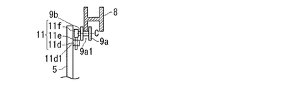
図4(A)は、図3(A)の部分拡大図である。図4(B)は、図4(A)のB−B矢視図である。図4(C)は、図4(A)のC−C矢視図である。 FIG. 4A is a partially enlarged view of FIG. FIG. 4B is a view taken along arrow BB in FIG. FIG. 4C is a CC arrow view of FIG.
第1実施形態では、図4に示すように、第1嵌合部9aは、ゲート体5に取り付けられたローラであり、第2嵌合部9bは、鉛直方向に延びるレールである。ローラ9aは、ゲート体5に対して水平な回転軸Cまわりに回転自在である。ローラ9aの外周面には、溝9a1が形成されている。溝9a1は、回転軸Cまわりの周方向に一周するように延びている。レール9bは、ローラ9aの溝9a1に嵌合している。この状態で、ローラ9aはレール9b上を鉛直方向に転動可能である。図4の例では、レール9bは、断面がH型の柱状部材8の一部として形成されている。
In the first embodiment, as shown in FIG. 4, the first
図2〜図4の例では、ゲート体5において、第1嵌合部9aは、水平幅方向Dの一端部における第1鉛直方向位置Pz1および第2鉛直方向位置Pz2と、水平幅方向Dの他端部における第1鉛直方向位置Pz1および第2鉛直方向位置Pz2とに設けられている。第1鉛直方向位置Pz1と第2鉛直方向位置Pz2は、鉛直方向における位置(高さ)である。第1鉛直方向位置Pz1は、ゲート体5の鉛直方向の中央よりも下方の位置であり、第2鉛直方向位置Pz2は、ゲート体5の鉛直方向の中央よりも上方の位置である。好ましくは、第1鉛直方向位置Pz1は、ゲート体5の下端部の位置であり、第2鉛直方向位置Pz2は、ゲート体5の上端部の位置である。
2 to 4, in the
図2〜図4の例において、第1嵌合部9aの数は、2つであってもよい。例えば、第1鉛直方向位置Pz1と第2鉛直方向位置Pz2の一方であって、かつ、水平幅方向Dのゲート体5の両端部にのみ、第1嵌合部9aがそれぞれ設けられてもよい。あるいは、水平幅方向Dのゲート体5の一端部であって、かつ、第1鉛直方向位置Pz1と第2鉛直方向位置Pz2にのみ、第1嵌合部9aがそれぞれ設けられてもよい。
2 to 4, the number of the first
調節機構11は、第1嵌合部9aと第2嵌合部9bの一方の位置を、水平方向(この例では、水平幅方向D)において、第1嵌合部9aと第2嵌合部9bの他方に対して調節可能である。
The
調節機構11は、例えば、長孔11aとボルト11bとナット11cを有する。長孔11aは、ゲート体5に形成されている。長孔11aは、ゲート体5の厚み方向にゲート体5を貫通している。この厚み方向は、水平幅方向Dと直交する水平方向である。また、長孔11aは、水平幅方向Dに細長く延びている。ボルト11bは、長孔11aを貫通するように配置される。ナット11cは、ボルト11bの一端側部分に螺合している。ボルト11bの他端側部分には、第1嵌合部9aが取り付けられている。第1嵌合部9aが上述のローラである場合には、ローラ9aは、ボルト11bの他端側部分に取り付けられた状態で、上述の回転軸Cまわりに回転自在になっている。このような調節機構11は、各第1嵌合部9aに設けられている。
The
調節機構11による第1嵌合部9aの位置調節では、ボルト11bへのナット11cの締め付けを緩める。この状態で、ボルト11bの位置を、長孔11aに沿って、ゲート体5に対して水平幅方向Dに調節できる。したがって、ボルト11bに取り付けられている第1嵌合部9aの位置も調節できる。この調節後に、ナット11cをボルト11bに締め付けて、ナット11cと、ボルト11bの他端側部分とでゲート体5を挟み込む。これにより、第1嵌合部9aがゲート体5に固定される。
In adjusting the position of the first
(第1実施形態による効果)
上述した第1実施形態による前面ゲート装置10では、ゲート体5を1本の索状体7aで吊るし、索状体7aを駆動することによりゲート体5を昇降する。この場合に、索状体7aの一端部7a1がゲート体5に結合している結合位置Pは、ゲート体5の水平幅方向Dにおいて、ゲート体5の重心と一致しており又は該重心に近接している。したがって、索状体7aは、途中で従動滑車に掛けられることなく、結合位置Pから索状体駆動装置7bまで直線状に鉛直方向に延びるように配置される。よって、ゲート体5を駆動するための索状体7aを短くでき、従動滑車を設けることが不要になる。
(Effect by 1st Embodiment)
In the
また、ワイヤーロープ7aは従動滑車に掛けられないので、ワイヤーロープ7aは、従動滑車により摩耗することがなくなる。これに対し、従来では、ゲート体を吊るすワイヤーロープは複数の従動滑車に掛けられているので、ワイヤーロープまたは従動滑車が摩耗してしまう。この問題が、第1実施形態の構成により解決される。
Further, since the
<第2実施形態>
図5は、第2実施形態による前面ゲート装置10を示す平面図である。図6(A)は、図5のVIAーVIA矢視図である。図6(B)は、図6(A)と同じ矢視図であり、ゲート体5が入庫用通路2を開けた状態を示す。図7(A)は、図6(A)のVIIA−VIIA矢視図である。図7(B)は、図6(B)のVIIBーVIIB矢視図である。
Second Embodiment
FIG. 5 is a plan view showing the
以下において、図5〜図7に基づいて、第2実施形態について説明する。以下において説明しない、第2実施形態の構成および動作は、第1実施形態と同じである。 Hereinafter, a second embodiment will be described based on FIGS. The configuration and operation of the second embodiment, which will not be described below, are the same as those of the first embodiment.
図6(A)のように、ゲート体5が上昇位置にある時に、ゲート体5は入庫用通路2を閉じる。この時、ゲート体5は、入庫用通路2の路面2aよりも上方側に位置する。
As shown in FIG. 6A, when the
一方、図6(B)のように、ゲート体5が下降位置にある時に、ゲート体5は入庫用通路2を開ける。この時、ゲート体5は、入庫用通路2の路面2aよりも下方に位置する。そのために、ゲート体5、第2嵌合部(レール)9bの一部、索状体駆動装置7bなどを収容する下部空間Sが設けられる。
On the other hand, as shown in FIG. 6B, when the
下部空間Sは、入庫用通路2の路面2aよりも下方に位置する。この下部空間Sは、入庫用通路2の路面2aへの開口を有する。この開口を通して、ゲート体5は昇降される。なお、索状体駆動装置7bが設けられる支持体6は、入庫用通路2の路面2aよりも下方に位置する。すなわち、支持体6も下部空間Sに位置する。
The lower space S is located below the
なお、好ましくは、索状体7aの一端部7a1は、ゲート体5の下端部の結合位置Pに結合されている。第2実施形態でも、第1実施形態と同様の効果が得られる。
Preferably, one
本発明は上述した実施の形態に限定されず、本発明の要旨を逸脱しない範囲で種々変更を加え得ることは勿論である。例えば、第1実施形態または第2実施形態において、以下の変更例1〜4のいずれかを採用してもよいし、変更例1〜4の2つ以上を任意に組み合わせて採用してもよい。この場合に、以下で説明しない点は、上述と同じである。
The present invention is not limited to the above-described embodiment, and various changes can be made without departing from the scope of the present invention. For example, in the first embodiment or the second embodiment, any one of the following
(変更例1)
索状体7aは、チェーンであってもよい。この場合、索状体駆動装置7bは、ドラム15の代わりにスプロケットを有する。スプロケットにはチェーンが掛けられている。チェーンは、一端部7a1から上方に延びてスプロケットに掛けられている。スプロケットの回転により、チェーンを吊り下げ吊り上げる(上下に駆動する)。これによりゲート体5が昇降する。
(Modification 1)
The
(変更例2)
調節機構11は、他の構成により、第1嵌合部9aと第2嵌合部9bの一方の位置を、水平方向(水平幅方向D)において、第1嵌合部9aと第2嵌合部9bの他方に対して調節可能であってもよい。例えば、調節機構11は、図8に示す構成を有していてもよい。図8は、図4(B)と同じ矢視図である。図8は、調節機構11が図4(B)と異なる構成を有する場合を示す。
(Modification 2)
The
図8において、調節機構11は、ねじ穴形成部11dとねじ11eと取付部11fを有する。ねじ穴形成部11dは、ゲート体5に固定されている。ねじ穴形成部11dには、水平幅方向Dにねじ穴が貫通している。ねじ穴の内周面には雌ねじ11d1が形成されている。ねじ11eは、ねじ穴の雌ねじ11d1に螺合している。ねじ11eの先端部には、取付部11fが固定されている。取付部11fには、第1嵌合部9aが取り付けられている。ねじ11eの後端部に、ドライバーを係合させて、ドライバーによりねじ11eを回転させる。これにより、第2嵌合部9bに対する第1嵌合部9aの位置が水平幅方向Dに調節される。
In FIG. 8, the adjusting
また、第1嵌合部9aと第2嵌合部9bの向きは、各図の例に限定されない。すなわち、第1嵌合部9aと第2嵌合部9bの向きは、各図に示すこれらの向きと直交する方向を向いていてもよい(例えば、回転軸Cは、水平幅方向Dを向いていてもよい)。この場合には、調節機構11は、第1嵌合部9aと第2嵌合部9bの一方の位置を、水平幅方向Dと直交する水平方向において、第1嵌合部9aと第2嵌合部9bの他方に対して調節可能である。
Moreover, the direction of the 1st
(変更例3)
図9は、変更例3による前面ゲート装置10の正面図である。変更例3では、上述の結合位置P(索状体7aの一端部7a1)は、ゲート体5の水平幅方向Dにおいて、ゲート体5の重心Gから一方側にずれている。図9では、結合位置Pは、重心Gから左側にずれている。
(Modification 3)
FIG. 9 is a front view of the
図9の例では、2つの第1嵌合部9aがゲート体5に設けられている。一方の第1嵌合部9aは、水平幅方向Dの一方側(図9の左側)のゲート体5の端部における第1鉛直方向位置Pz1にある。他方の第1嵌合部9aは、水平幅方向Dの他方側(図9の右側)のゲート体5の端部における第2鉛直方向位置Pz2にある。好ましくは、第1嵌合部9aとして、これら2つのみが設けられる。ただし、本発明によると、これら2つの第1嵌合部9aのうち、いずれかを省略してもよい(すなわち、第1嵌合部9aを1つだけ設けてもよい)。この場合、省略する第1嵌合部9aが嵌合する第2嵌合部9bも省略してもよい。
In the example of FIG. 9, two first
なお、好ましくは、第1鉛直方向位置Pz1は、ゲート体5の下端部の位置であり、第2鉛直方向位置Pz2は、ゲート体5の上端部の位置である。
Preferably, the first vertical position Pz1 is the position of the lower end of the
変更例3では、ゲート体5には、その自重により回転モーメントが生じる。この回転モーメントは、図9において、結合位置Pを中心とした時計まわりの方向に生じる。これにより、第1嵌合部9aは、水平幅方向Dの一方側、または、該一方側と反対側(すなわち、他方側)へ第2嵌合部9bに押し付けられている。この状態で、第1嵌合部9aは、第2嵌合部9bに対して鉛直方向に移動可能になっている。図9の例では、左側の第1嵌合部9aは、水平幅方向Dの一方側(図9の左側)へ第2嵌合部9bに押し付けられる。また、図9の例では、右側の第1嵌合部9aは、水平幅方向Dの他方側(図9の右側)へ第2嵌合部9bに押し付けられる。
In the third modification, a rotational moment is generated in the
なお、図9は、変更例3を上述の第1実施形態に適用した場合を示しているが、変更例3を上述の第2実施形態に適用してもよい。 FIG. 9 shows a case where the third modification is applied to the first embodiment described above, but the third modification may be applied to the second embodiment described above.
(変更例4)
第1嵌合部9aは、鉛直方向に細長く延びていてもよい。例えば、第1嵌合部9aの鉛直方向寸法は、ゲート体5の鉛直方向寸法の1/3以上であってよい(一例では、ゲート体5の鉛直方向寸法と同じである)。これにより、第1嵌合部9aは、鉛直方向の広範囲にわたって、第2嵌合部9b(レール9b)に嵌合する。
(Modification 4)
The first
この場合、上述の変更例3では、第1嵌合部9aは、水平幅方向Dにおいて、重心Gから見て結合位置Pと反対側(図9の右側)に位置するゲート体5の端部に設けられるのがよい。
In this case, in the above-described third modification, the first
1 自動車、2 入庫用通路、2a 路面、3 パレット、5 ゲート体、6 支持体、7 昇降装置、7a 索状体、7a1 一端部、7b 索状体駆動装置、8 柱状部材、9 案内機構、9a 第1嵌合部(ローラ)、9a1 溝、9b 第2嵌合部(レール)、10 前面ゲート装置、11 調節機構、11a 長孔、11b ボルト、11c ナット、11d ねじ穴形成部、11d1 雌ねじ、11e ねじ、11f 取付部、13 モータ、15 ドラム、20 機械式駐車装置、R 駐車装置内の領域、D 水平幅方向、P 結合位置、Pz1 第1鉛直方向位置、Pz2 第2鉛直方向位置、C 回転軸、S 下部空間
DESCRIPTION OF
Claims (9)
昇降駆動されることにより、機械式駐車装置内へ自動車が進入するための入庫用通路を開閉するゲート体と、
前記ゲート体を昇降する昇降装置と、を備え、
前記昇降装置は、
前記ゲート体に結合された一端部を有し、該一端部から上方に延びて前記ゲート体を吊るす索状体と、
前記索状体を吊り上げ吊り下げることにより前記索状体を介して前記ゲート体を昇降する索状体駆動装置と、を備え、
前記索状体は、前記一端部から前記索状体駆動装置までの範囲において、鉛直方向へ直線状に延びている、前面ゲート装置。 A front gate device in a mechanical parking device,
By being driven up and down, a gate body that opens and closes the entry passage for the car to enter the mechanical parking device,
An elevating device for elevating and lowering the gate body,
The lifting device is
A cord-like body having one end coupled to the gate body and extending upward from the one end to suspend the gate body;
A cord drive device that lifts and lowers the gate body via the cord by lifting and hanging the cord; and
The cord-like body is a front gate device that extends linearly in a vertical direction in a range from the one end to the cord-like driving device.
該案内機構は、互いに嵌合する第1嵌合部と第2嵌合部を有し、
第1嵌合部は、前記ゲート体の水平幅方向における前記ゲート体の両端部に設けられ、
第2嵌合部は、前記水平幅方向におけるゲート体の両側に設けられ、前記両端部の第1嵌合部にそれぞれ嵌合しており、
第1嵌合部は、第2嵌合部に対して鉛直方向に移動可能になっている、請求項1または2に記載の前面ゲート装置。 A guide mechanism for guiding the raising and lowering of the gate body;
The guide mechanism has a first fitting portion and a second fitting portion that are fitted together,
The first fitting portion is provided at both ends of the gate body in the horizontal width direction of the gate body,
The second fitting portions are provided on both sides of the gate body in the horizontal width direction, and are fitted to the first fitting portions at both ends,
The front gate device according to claim 1 or 2, wherein the first fitting portion is movable in a vertical direction with respect to the second fitting portion.
前記ゲート体の昇降を案内する案内機構を備え、
該案内機構は、互いに嵌合する第1嵌合部と第2嵌合部を有し、
第1嵌合部は、前記水平幅方向におけるゲート体の端部に設けられ、
第2嵌合部は、第1嵌合部に嵌合しており、
第1嵌合部は、前記水平幅方向の前記一方側または他方側へ第2嵌合部に押し付けられた状態で、第2嵌合部に対して鉛直方向に移動可能になっている、請求項1に記載の前面ゲート装置。 The coupling position where the one end of the cord-like body is coupled to the gate body is shifted to one side from the center of gravity of the gate body in the horizontal width direction of the gate body,
A guide mechanism for guiding the raising and lowering of the gate body;
The guide mechanism has a first fitting portion and a second fitting portion that are fitted together,
The first fitting portion is provided at an end portion of the gate body in the horizontal width direction,
The second fitting portion is fitted to the first fitting portion,
The first fitting portion is movable in the vertical direction with respect to the second fitting portion in a state where the first fitting portion is pressed against the second fitting portion toward the one side or the other side in the horizontal width direction. Item 6. The front gate device according to Item 1.
第1鉛直方向位置は、前記ゲート体の鉛直方向の中央よりも下方の位置であり、第2鉛直方向位置は、前記ゲート体の鉛直方向の中央よりも上方の位置である、請求項4に記載の前面ゲート装置。 In the gate body, the first fitting portion includes a first vertical position of an end located on the one side in the horizontal width direction and a second vertical position of an end located on the other side in the horizontal width direction. It is provided in the direction position,
The first vertical direction position is a position below the center of the gate body in the vertical direction, and the second vertical direction position is a position above the center of the gate body in the vertical direction. The front gate device as described.
該ローラは、前記ゲート体に対して水平な回転軸まわりに回転自在であり、
前記ローラの外周面には、溝が形成されており、該溝は、前記回転軸まわりに1周するように延びており、
第2嵌合部は、鉛直方向に延びるレールであり、該レールは、前記溝に嵌合している、請求項3〜5のいずれか一項に記載の前面ゲート装置。 The first fitting portion is a roller attached to the gate body,
The roller is rotatable about a rotation axis horizontal to the gate body;
A groove is formed on the outer peripheral surface of the roller, and the groove extends so as to make one turn around the rotation axis.
The front gate device according to any one of claims 3 to 5, wherein the second fitting portion is a rail extending in a vertical direction, and the rail is fitted in the groove.
前記長孔を貫通するボルトと、
前記ボルトの一端側部分に螺合するナットとを有し、
前記ボルトの他端側部分には、第1嵌合部が取り付けられており、
前記ナットと、前記ボルトの他端側部分とでゲート体を挟み込むことにより、第1嵌合部がゲート体に固定される、請求項7に記載の前面ゲート装置。 The adjustment mechanism includes a long hole provided in the gate body and extending in the horizontal width direction;
A bolt penetrating the elongated hole;
A nut that is screwed to one end portion of the bolt;
A first fitting portion is attached to the other end portion of the bolt,
The front gate device according to claim 7, wherein the first fitting portion is fixed to the gate body by sandwiching the gate body between the nut and the other end portion of the bolt.
Priority Applications (1)
| Application Number | Priority Date | Filing Date | Title |
|---|---|---|---|
| JP2016001489A JP2017122342A (en) | 2016-01-07 | 2016-01-07 | Front gate device for mechanical parking device |
Applications Claiming Priority (1)
| Application Number | Priority Date | Filing Date | Title |
|---|---|---|---|
| JP2016001489A JP2017122342A (en) | 2016-01-07 | 2016-01-07 | Front gate device for mechanical parking device |
Publications (1)
| Publication Number | Publication Date |
|---|---|
| JP2017122342A true JP2017122342A (en) | 2017-07-13 |
Family
ID=59305569
Family Applications (1)
| Application Number | Title | Priority Date | Filing Date |
|---|---|---|---|
| JP2016001489A Pending JP2017122342A (en) | 2016-01-07 | 2016-01-07 | Front gate device for mechanical parking device |
Country Status (1)
| Country | Link |
|---|---|
| JP (1) | JP2017122342A (en) |
Cited By (1)
| Publication number | Priority date | Publication date | Assignee | Title |
|---|---|---|---|---|
| JP7450480B2 (en) | 2020-07-03 | 2024-03-15 | 日栄インテック株式会社 | mechanical parking device |
Citations (4)
| Publication number | Priority date | Publication date | Assignee | Title |
|---|---|---|---|---|
| JPH07180385A (en) * | 1993-12-24 | 1995-07-18 | Nhk Spring Co Ltd | Parking facility managing device |
| WO1999040282A1 (en) * | 1998-02-04 | 1999-08-12 | Steris Corporation | Door safety stopper |
| JP2005083100A (en) * | 2003-09-09 | 2005-03-31 | Tokyu Car Corp | Parking equipment |
| US20050072535A1 (en) * | 2002-03-21 | 2005-04-07 | Kenneth David | Overhead door drop stop |
-
2016
- 2016-01-07 JP JP2016001489A patent/JP2017122342A/en active Pending
Patent Citations (4)
| Publication number | Priority date | Publication date | Assignee | Title |
|---|---|---|---|---|
| JPH07180385A (en) * | 1993-12-24 | 1995-07-18 | Nhk Spring Co Ltd | Parking facility managing device |
| WO1999040282A1 (en) * | 1998-02-04 | 1999-08-12 | Steris Corporation | Door safety stopper |
| US20050072535A1 (en) * | 2002-03-21 | 2005-04-07 | Kenneth David | Overhead door drop stop |
| JP2005083100A (en) * | 2003-09-09 | 2005-03-31 | Tokyu Car Corp | Parking equipment |
Cited By (1)
| Publication number | Priority date | Publication date | Assignee | Title |
|---|---|---|---|---|
| JP7450480B2 (en) | 2020-07-03 | 2024-03-15 | 日栄インテック株式会社 | mechanical parking device |
Similar Documents
| Publication | Publication Date | Title |
|---|---|---|
| JP4842112B2 (en) | Elevator governor rope steady rest | |
| JP2004322823A (en) | Simple movable fence of platform | |
| JP2009143637A (en) | Rope steady brace of elevator | |
| KR20150013410A (en) | Apparatus for elevating screen doors of vertical open-close type | |
| JP2017036628A (en) | Split door structure | |
| JP6270082B2 (en) | Sluice opener | |
| JP2017122342A (en) | Front gate device for mechanical parking device | |
| JP2007002607A (en) | Hinge device and automatic collapsible lifting gate with the same | |
| KR102276971B1 (en) | Emergency stop device of elevator and elevator used this | |
| KR102151698B1 (en) | Safe lifting and lowering device for stage equipment | |
| JP2001328797A (en) | Lift device for storage | |
| KR101532914B1 (en) | Driving apparatus for opening and closing of overhaed door | |
| WO2018229860A1 (en) | Device for preventing shaking of main rope for elevator | |
| JP3583384B2 (en) | Chain gate | |
| JP2002226161A (en) | Upward sliding door device for elevator | |
| JP6472654B2 (en) | Home fence | |
| JP3510966B2 (en) | Blind cold shutter | |
| KR200355684Y1 (en) | Safety apparatus for preventing a drop of a canvas door | |
| JP4290595B2 (en) | Overhead door | |
| JP5238363B2 (en) | Elevator safety device | |
| JP4941759B2 (en) | Goods storage equipment | |
| KR102377496B1 (en) | Wire rope anti-shake safety device for stage equipment | |
| JP3637339B2 (en) | Gate device | |
| KR101830837B1 (en) | Tension device for elevator governor rope | |
| JP6258129B2 (en) | Lifting device for small luggage |
Legal Events
| Date | Code | Title | Description |
|---|---|---|---|
| A621 | Written request for application examination |
Free format text: JAPANESE INTERMEDIATE CODE: A621 Effective date: 20181130 |
|
| A977 | Report on retrieval |
Free format text: JAPANESE INTERMEDIATE CODE: A971007 Effective date: 20191017 |
|
| A131 | Notification of reasons for refusal |
Free format text: JAPANESE INTERMEDIATE CODE: A131 Effective date: 20191108 |
|
| A02 | Decision of refusal |
Free format text: JAPANESE INTERMEDIATE CODE: A02 Effective date: 20200513 |