JP2017121383A - Measurement system for biological activity attributed to respiration of subject - Google Patents
Measurement system for biological activity attributed to respiration of subject Download PDFInfo
- Publication number
- JP2017121383A JP2017121383A JP2016002073A JP2016002073A JP2017121383A JP 2017121383 A JP2017121383 A JP 2017121383A JP 2016002073 A JP2016002073 A JP 2016002073A JP 2016002073 A JP2016002073 A JP 2016002073A JP 2017121383 A JP2017121383 A JP 2017121383A
- Authority
- JP
- Japan
- Prior art keywords
- marker
- subject
- light
- measurement system
- point
- Prior art date
- Legal status (The legal status is an assumption and is not a legal conclusion. Google has not performed a legal analysis and makes no representation as to the accuracy of the status listed.)
- Pending
Links
Images


Classifications
-
- A—HUMAN NECESSITIES
- A61—MEDICAL OR VETERINARY SCIENCE; HYGIENE
- A61B—DIAGNOSIS; SURGERY; IDENTIFICATION
- A61B5/00—Measuring for diagnostic purposes; Identification of persons
- A61B5/08—Detecting, measuring or recording devices for evaluating the respiratory organs
-
- A—HUMAN NECESSITIES
- A61—MEDICAL OR VETERINARY SCIENCE; HYGIENE
- A61B—DIAGNOSIS; SURGERY; IDENTIFICATION
- A61B5/00—Measuring for diagnostic purposes; Identification of persons
- A61B5/103—Detecting, measuring or recording devices for testing the shape, pattern, colour, size or movement of the body or parts thereof, for diagnostic purposes
- A61B5/11—Measuring movement of the entire body or parts thereof, e.g. head or hand tremor, mobility of a limb
Abstract
Description
本発明は、被験者の映像から被験者の呼吸数等の、呼吸に起因する生体活動を計測するための技術に関する。 The present invention relates to a technique for measuring a biological activity resulting from respiration, such as a subject's respiration rate, from a subject's video.
カメラで被験者を撮影し、その動画像から体動や血流などの生体反応による輝度値の変化を検出し、被験者の呼吸数、心拍数等の生体活動を計測する技術が知られている(たとえば特許文献1および2)。被験者が写る画像領域は、観測者が予め指定したり、輪郭抽出技術を用いたりすることによって特定される。
A technique is known in which a subject is photographed with a camera, a change in luminance value due to a biological reaction such as body movement or blood flow is detected from the moving image, and a biological activity such as a subject's respiratory rate or heart rate is measured ( For example,
特許文献1の呼吸モニタリング装置は、被験者を撮影した画像を局所領域に分割し、それぞれの局所領域の明度情報を解析する。そして、三種類のしきい値を用いて、被験者の胸部周辺の動きを観測しているのか、寝返りなどの非呼吸体動を観測しているかを判定する。
The respiratory monitoring device of
特許文献2の心拍数計測装置は、赤外線光源を搭載したカメラで被験者の顔面を撮影し、フレームごとの顔画像から、眉間の特定領域を抽出してその平均輝度を補正する。心拍数計測装置は、補正された平均輝度の時系列から補正輝度の時間的変化の波形を得て、この波形を心拍数に対応する周波数帯でフィルタリングすることで、被験者の心拍数を算出する。
The heart rate measuring device of
特許文献1の呼吸モニタリング装置においては、非呼吸体動の判定に必要な適切なしきい値は、撮影環境に応じて大きく変動する。たとえば観測場所の明るさの変化、室内光源の位置、外部からの入射光の有無、被撮影者以外の人や物の移動により、設定すべきしきい値が大きく変動し得る。常に適切なしきい値を求める方法がないため、しきい値が不適切な場合は、呼吸などの生体情報を求めるための領域を算出することができない。
In the respiratory monitoring device of
特許文献2の心拍数計測装置は、被験者の顔面を撮像範囲に捉えて撮影する必要がある。特許文献1と同様、照度の変化、人の動き、外部光の入射など撮影環境が変化すると、生体活動以外の原因で、被験者が写る画像領域の輝度値が大きく変化する。このような外乱ノイズが発生すると、生体反応に起因した体動個所を特定できず、生体情報が正確に抽出できないことがある。
The heart rate measuring device of
さらに、被験者の顔面がカメラから離れると被験者の生体情報を取得する精度が落ちるため、比較的近距離から被験者の顔面を撮像し続けなければならない。その結果、被験者に圧迫感を与えてしまい、計測対象となる生体活動への影響が懸念される。 Furthermore, since the accuracy of acquiring the subject's biological information decreases when the subject's face moves away from the camera, the subject's face must be continuously imaged from a relatively short distance. As a result, a feeling of pressure is given to the subject, and there is a concern about the influence on the biological activity to be measured.
本発明は、上記課題を解決するためになされたものであって、生体活動の計測条件が周囲の環境の影響を受けにくい、呼吸に起因する生体活動の計測システム(以下、「計測システム」と表記する。)を提供する。 The present invention has been made to solve the above-described problems, and is a measurement system for life activity caused by breathing (hereinafter referred to as “measurement system”) in which measurement conditions for life activity are not easily influenced by the surrounding environment. Provided.)
本発明の実施形態による計測システムは、光を放射する光源と、前記光を受けて動画像を生成する撮像装置と、前記動画像を利用して被験体の生体活動を計測する画像処理回路とを備える計測システムであって、前記被験体の呼吸に伴う体動の発生位置に反射マーカが配置され、前記光源から、前記被験体に向けて前記光が放射されたときにおいて、前記撮像装置は、前記反射マーカで反射された前記光を複数の時刻において受けて、時系列の複数のフレーム画像から構成される前記動画像を生成し、前記画像処理回路は、前記撮像装置から前記動画像を受け取り、前記複数のフレーム画像の輝度値の変化に基づいて前記被験体の呼吸に起因する生体活動を計測し、前記反射マーカは、支持面を有するベースと、各々が前記支持面に対して傾斜し、前記支持面で支持された複数の反射材と、を有する。 A measurement system according to an embodiment of the present invention includes a light source that emits light, an imaging device that receives the light and generates a moving image, and an image processing circuit that measures a biological activity of a subject using the moving image. A reflection marker is disposed at a position where body movement occurs due to breathing of the subject, and when the light is emitted from the light source toward the subject, the imaging device is Receiving the light reflected by the reflective marker at a plurality of times, generating the moving image composed of a plurality of time-series frame images, and the image processing circuit receiving the moving image from the imaging device. Receiving and measuring a biological activity caused by respiration of the subject based on a change in luminance values of the plurality of frame images, and the reflective marker includes a base having a support surface and each of which is inclined with respect to the support surface. And, having a plurality of reflective material which is supported by the support surface.
ある実施形態において、前記反射マーカは再帰性反射マーカであり、前記複数の反射材は複数の再帰性反射材であってもよい。 In one embodiment, the reflective marker may be a retroreflective marker, and the plurality of reflective materials may be a plurality of retroreflective materials.
ある実施形態において、前記反射マーカが前記被験体の呼吸に伴う体動の発生位置に配置されたときにおいて、前記複数の反射材の各々の傾斜角度は前記光源に近い側から遠ざかるにつれて大きくなってもよい。 In one embodiment, when the reflective marker is disposed at a position where body movement occurs due to breathing of the subject, the inclination angle of each of the plurality of reflectors increases as the distance from the side closer to the light source increases. Also good.
ある実施形態において、前記反射マーカの側面は、前記複数の反射材に対応した複数の鋸歯を含む鋸歯状の構造を含み、前記複数の鋸歯の各々の高さは等しく、前記反射マーカが前記被験体の呼吸に伴う体動の発生位置に配置されたときにおいて、鋸歯のピッチは、前記光源に近い側から遠ざかるにつれて小さくなってもよい。 In one embodiment, a side surface of the reflective marker includes a saw-tooth structure including a plurality of saw teeth corresponding to the plurality of reflectors, and the height of each of the plurality of saw teeth is equal, and the reflective marker is the test marker. When the body movement is generated at the position where the body respiration occurs, the pitch of the sawtooth may be reduced as the distance from the side closer to the light source is increased.
ある実施形態において、前記複数の反射材の各々は、曲面形状の反射面を有していてもよい。 In one embodiment, each of the plurality of reflecting materials may have a curved reflecting surface.
ある実施形態において、前記曲面形状は、隣接する2つの反射材の曲面上の任意の点における法線に対する前記光の入射角度が全て等しくなる放物線によって規定される凹面鏡の形状に等しくてもよく、前記複数の反射材の配列方向に平行な第1の方向に直交し、各反射材が延伸する第2の方向および前記第1の方向の両方に直交する第3の方向と、前記第1の方向と、にそれぞれ平行な面で切断した、前記各反射材の曲面の断面において、前記各反射材の前記撮像装置側の第1の端に位置する曲面上の点を点Rとし、前記各反射材の前記撮像装置とは反対側の第2の端に位置する曲面上の点を点Sとし、前記凹面鏡の焦点距離をfとし、物点を点Cとし、像点を点C’とすると、線分RSの垂直二等分線は、線分CC’の中点で前記線分CC’と直交し、かつ、前記凹面鏡の焦点は前記線分RSの垂直二等分線上に位置し、かつ、前記線分RSと前記線分CC’との距離が2fの長さであってもよい。 In one embodiment, the curved surface shape may be equal to the shape of a concave mirror defined by a parabola in which the incident angles of the light with respect to the normal at any point on the curved surface of two adjacent reflectors are all equal, A third direction orthogonal to a first direction parallel to an arrangement direction of the plurality of reflective materials, each of the second direction in which each reflective material extends, and a third direction orthogonal to both the first directions, and the first In the cross-section of the curved surface of each of the reflecting materials cut by a plane parallel to each direction, a point on the curved surface located at the first end of each reflecting material on the imaging device side is a point R, A point on the curved surface located at the second end of the reflector opposite to the imaging device is a point S, a focal length of the concave mirror is f, an object point is a point C, and an image point is a point C ′. Then, the perpendicular bisector of the line segment RS is the line segment C ′ at the midpoint of the line segment CC ′. And the focal point of the concave mirror is located on a perpendicular bisector of the line segment RS, and the distance between the line segment RS and the line segment CC ′ is 2f in length. Good.
ある実施形態において、前記反射マーカは、所定のマーカ形状を有した開口を含むカバーをさらに有し、平面視において、前記複数の反射材の形状は、前記所定のマーカ形状に一致してもよい。 In one embodiment, the reflective marker further includes a cover including an opening having a predetermined marker shape, and the shapes of the plurality of reflective materials may coincide with the predetermined marker shape in a plan view. .
ある実施形態において、前記所定のマーカ形状は、三角形、ひし形または矩形であってもよい。 In one embodiment, the predetermined marker shape may be a triangle, a diamond, or a rectangle.
ある実施形態において、前記画像処理回路は、各フレーム画像を複数の部分領域に分割し、前記複数の部分領域の輝度値の変化に基づいて前記被験体の呼吸に起因する生体活動を計測してもよい。 In one embodiment, the image processing circuit divides each frame image into a plurality of partial areas, and measures a biological activity caused by breathing of the subject based on a change in luminance value of the plurality of partial areas. Also good.
ある実施形態において、前記光源は、赤外光線を放射する赤外線光源であり、前記撮像装置は、可視光領域の波長を遮る光学フィルタを含んでいてもよい。 In one embodiment, the light source is an infrared light source that emits infrared light, and the imaging device may include an optical filter that blocks a wavelength in a visible light region.
本発明によれば、傾斜した複数の反射材を含む反射マーカを用いることにより、生体活動の計測条件が周囲の環境の影響を受けにくい、呼吸に起因する生体活動の計測システムが提供される。 ADVANTAGE OF THE INVENTION According to this invention, the measurement system of the biological activity resulting from the respiration which the measurement condition of a biological activity is hard to be influenced by the surrounding environment by using the reflective marker containing the several inclined reflective material is provided.
生体活動の計測条件が周囲の環境の影響を受けにくい計測システムが望まれている。例えば、再帰性反射材を用いて、被験者の呼吸に起因する生体活動を計測することが提案されている。具体的に説明すると、被験者の呼吸に伴う体動の発生位置、例えば胸部に、平坦な再帰性反射材がマーカとして配置され、赤外線光源から赤外光がマーカに向けて放射される。カメラがマーカを含む動画像を撮像し、画像処理回路が、取得された動画像を構成する複数のフレーム画像の輝度値の変化に基づいて被験者の呼吸に起因する生体活動を計測することができる。再帰性反射材をマーカとして用いることにより、マーカ領域の輝度を向上させてSN比(Signal Noise Ratio)を確保することができる。このような計測システムおよび計測方法は、例えば本出願人による未公開の特許出願である特願2014−145476号に開示されている。この開示内容の全てを参考のために本願明細書に援用する。なお、本明細書では、被験者は人であるとして説明するが、人以外の動物(犬や猫などのペット動物、豚やマウスなどの実験動物)であってもよい。観測対象としての動物(人を含む。)を総称して「被験体」と呼ぶことがある。 There is a demand for a measurement system in which measurement conditions for life activity are not easily influenced by the surrounding environment. For example, it has been proposed to use a retroreflective material to measure the biological activity resulting from the subject's breathing. More specifically, a flat retroreflecting material is arranged as a marker at a position where body movement accompanying breathing of the subject, for example, the chest, and infrared light is emitted from the infrared light source toward the marker. The camera captures a moving image including a marker, and the image processing circuit can measure a biological activity caused by the breathing of the subject based on a change in luminance values of a plurality of frame images constituting the acquired moving image. . By using the retroreflective material as a marker, the brightness of the marker region can be improved and the SN ratio (Signal Noise Ratio) can be ensured. Such a measurement system and measurement method are disclosed in, for example, Japanese Patent Application No. 2014-145476, which is an unpublished patent application by the present applicant. All of this disclosure is incorporated herein by reference. In the present specification, the subject is described as being a person, but may be an animal other than a person (a pet animal such as a dog or a cat, or an experimental animal such as a pig or a mouse). Animals (including people) as observation targets may be collectively referred to as “subjects”.
本願発明者の検討によると、再帰性反射材の反射率は、再帰性反射材に対する光の入射角度に強く依存する。再帰性反射材に対する光の入射角度が大きくなると反射率は著しく低下し得る。その結果、撮影画像においてマーカ領域の一部分の輝度が低下して、マーカ領域に輝度ムラが生じる可能性がある。 According to the study by the present inventor, the reflectance of the retroreflective material strongly depends on the incident angle of light with respect to the retroreflective material. As the incident angle of light with respect to the retroreflective material increases, the reflectance can be significantly reduced. As a result, the luminance of a part of the marker area in the photographed image may decrease, and luminance unevenness may occur in the marker area.
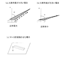
光源から再帰性反射材に光が入射する入射角度は被験者と光源との位置関係などに依存して変化し得る。図1(a)は、光の入射角度αが比較的小さい場合における、再帰性反射材で反射された反射光を模式的に示し、図1(b)は、光の入射角度αが比較的大きい場合における、再帰性反射材で反射された反射光を模式的に示し、図1(c)は、設置面(例えば胸部)に対して傾斜させて配置した単一のマーカを模式的に示している。図示するように、光の入射角度は法線nに対してなす角度である。再帰性反射材の領域で光源により近い部分では、図1(a)に示すように、再帰性反射材に対する光の入射角度αは相対的に小さく、その結果、光の反射率は高くなり、その領域では輝度を確保することができる。一方、再帰性反射材の領域で光源から遠ざかる領域では、図1(b)に示すように、再帰性反射材に対する光の入射角度αは徐々に大きくなる。例えば、光源の設置位置が低い場合には、光の入射角度αは一層大きくなると考えられる。その結果、光の反射率も徐々に低下し、その領域では輝度を確保することが困難となる。マーカの輝度が十分でない場合、後述するマーカ検出に影響が及ぶ可能性がある。 The incident angle at which light enters the retroreflecting material from the light source can vary depending on the positional relationship between the subject and the light source. FIG. 1A schematically shows the reflected light reflected by the retroreflecting material when the light incident angle α is relatively small, and FIG. 1B shows that the light incident angle α is relatively small. The reflected light reflected by the retroreflecting material in a large case is schematically shown, and FIG. 1C schematically shows a single marker arranged to be inclined with respect to the installation surface (for example, the chest). ing. As shown in the figure, the incident angle of light is an angle formed with respect to the normal line n. In the portion of the retroreflective material that is closer to the light source, as shown in FIG. 1A, the incident angle α of the light with respect to the retroreflective material is relatively small, and as a result, the reflectance of the light is high, Luminance can be ensured in that region. On the other hand, in the region of the retroreflective material that is away from the light source, the incident angle α of light with respect to the retroreflective material gradually increases as shown in FIG. For example, when the installation position of the light source is low, it is considered that the light incident angle α is further increased. As a result, the reflectance of light gradually decreases, and it is difficult to ensure luminance in that region. When the brightness of the marker is not sufficient, there is a possibility of affecting marker detection described later.
特許文献3が、複数の傾斜面を含む再帰性反射材と、光源およびラインセンサが一体となって構成された2つのセンサユニットとを備えた座標入力装置を開示している。複数の傾斜面の傾斜角度は、光源からの光の入射角度を考慮して決定される。特許文献3によれば、道路標識等の用途で市販されている再帰性反射材の中で、再帰反射効率が比較的高いとされ、かつ、最も広角な特性を有する再帰性反射材でも、光の入射角度が30°〜45°以上では再帰反射効率が急激に低下するとされている。 Patent Document 3 discloses a coordinate input device including a retroreflecting material including a plurality of inclined surfaces and two sensor units in which a light source and a line sensor are integrated. The inclination angles of the plurality of inclined surfaces are determined in consideration of the incident angle of light from the light source. According to Patent Document 3, among retroreflective materials marketed for applications such as road signs, the retroreflective efficiency is relatively high, and even with the most wide-angle characteristics, When the incident angle is 30 ° to 45 ° or more, the retroreflection efficiency is drastically reduced.
このような課題を解決するために、例えば図1(c)に示すように、マーカ自体を傾斜させて配置することにより、再帰性反射材に対する光の入射角度を相対的に小さくして輝度を確保することが考えられる。しかしながら、このような構成によると、マーカの高さが高くなることにより、マーカの取扱いが不便になるばかりでなく、マーカと被験者とは密着せず、それらの接触面積が小さくなることによって、マーカは生体活動に起因して発生する体動を拾うことができない恐れがある。このことは、呼吸に起因する生体活動を正確に計測できないことに繋がる。 In order to solve such a problem, for example, as shown in FIG. 1 (c), by arranging the marker itself to be inclined, the incident angle of the light with respect to the retroreflecting material is relatively reduced, thereby increasing the luminance. It is conceivable to secure. However, according to such a configuration, the height of the marker is not only inconvenient to handle the marker, but the marker and the subject are not in close contact with each other, and the contact area thereof is reduced. May not be able to pick up body movements caused by biological activity. This leads to a failure to accurately measure the biological activity resulting from respiration.
本願発明者は、上記の知見に基づいて、新規な構造を備えた反射マーカを見出し、本発明に至った。本明細書では、再帰性反射マーカを計測用マーカとして主に利用する計測システムを例に実施の形態1から3を説明する。ただし、後述するように、所定の条件下では、計測用マーカは、必ずしも再帰性反射マーカでなくてもよい。
Based on the above findings, the inventor of the present application has found a reflective marker having a novel structure, and has reached the present invention. In the present specification,
以下、添付の図面を参照しながら、本発明の実施形態による計測システムを説明する。以下の説明において、同一または類似する構成要素については同一の参照符号を付している。なお、本発明の実施の形態による計測システムは、以下で例示するものに限られない。例えば、一の実施の形態と、他の実施の形態とを組み合わせることも可能である。 Hereinafter, a measurement system according to an embodiment of the present invention will be described with reference to the accompanying drawings. In the following description, the same reference numerals are assigned to the same or similar components. In addition, the measurement system by embodiment of this invention is not restricted to what is illustrated below. For example, it is possible to combine one embodiment with another embodiment.
(実施の形態1)
図2は、本実施の形態による計測システム100の構成を示す。計測システム100は、カメラ10と、光源20と、情報処理装置30と、再帰性反射マーカ40とを含む。計測システム100は、被験者1の生体活動を観察するために利用される。本実施の形態では、生体活動は被験者1の呼吸であるとし、計測システム100は所定時間内の呼吸数を計測する。図2には被験者1が示されているが、被験者1は計測システム100に含まれない。
(Embodiment 1)
FIG. 2 shows a configuration of the
カメラ10は、イメージセンサおよびレンズ光学系を含む、いわゆる撮像装置であり、被験者1を撮影して動画像を生成する。カメラ10は、有線または無線で動画像のデータを情報処理装置30に送る。
The
光源20は光20aを放射する光源である。光は可視光であってもよく、不可視光(たとえば赤外光)であってもよい。本実施の形態では、赤外光を例に挙げて説明する。以下では、光20aを「赤外光20a」と記述する。
The
情報処理装置30は、カメラ10が撮影した動画像のデータを受け取り、動画像を構成する複数のフレーム画像間の画像の変化を利用して被験者1の呼吸数を計測する。情報処理装置30の動作の詳細は後述する。
The
図3は、再帰性反射マーカ40の斜視図である。図4は、再帰性反射マーカ40の上面図である。図5は、カバー43を備えた再帰性反射マーカ40の分解斜視図である。図6は、カバー43を備えた再帰性反射マーカ40の平面図である。図7は、カバー43の開口44によってひし形に形成された再帰性反射材42に光源20からの赤外光20aを照射している状態を示す。
FIG. 3 is a perspective view of the
再帰性反射マーカ40は、平坦な支持面41aを有するベース41と、各々が同一の傾斜方向(図3のY方向)を向いて支持面41aに対して所定の傾斜角度で傾斜し、支持面41aによって支持された複数の再帰性反射材42と、を有する。なお、支持面41aは、再帰性反射マーカ40が被験者1に配置されたとき、被験者1に接触する面である。本実施の形態では、再帰性反射材42の傾斜角度は、全て等しくなるように設定されている。ただし、傾斜角度は、それぞれの再帰性反射材42に入射する光の入射角度が最適になるように独立して設定され得る。また、再帰性反射材42の使用枚数は、カメラ10が配置される位置や被験者1の大きさなどを考慮し、製品仕様などによって適宜決定され得る。
The
再帰性反射材42の形状は、図示するように典型的には略矩形であり得るが、例えば円形や楕円形であってもよい。図3のZ方向から見た再帰性反射マーカ40の側面は、複数の再帰性反射材42に対応した複数の鋸歯を含む鋸歯状の構造を含んでいる。本実施の形態では、製造のし易さなどを考慮して、再帰性反射材42の高さh、つまり鋸歯の高さh(支持面41aから鋸歯の頂点までの距離)を全て等しくしている。ただし、再帰性反射材42の高さhは、全て等しくなくても構わない。
The shape of the
再帰性反射材42は、入射してきた光を、その入射方向に向けて反射する光学特性を有する反射材である。つまり、再帰性反射材42に入射する光の入射角度と、再帰性反射材42によって反射された光の出射角度とは等しい。ただしこの性質は理想的であり、実際には一部の入射方向とは異なる方向に反射され得る。本実施の形態では、光源20の光軸とカメラ10の光軸とを近接して配置させている。これにより、光源20から放射された赤外光20aは再帰性反射材42に反射され、その多くが赤外光20bとしてカメラ10に入射する。よって、カメラ10は十分な光量で被験者1を撮影することができる。再帰性反射材42として、例えばガラスビーズを塗布した布を用いることができる。
The
傾斜した複数の再帰性反射材42を含む再帰性反射マーカ40を用いることにより、カメラ10から離れて配置された再帰性反射材42に入射する光の入射角度をも小さくすることが可能となり、その再帰性反射材42の領域の輝度の低下は抑制され得る。また、図示するような、再帰性反射材42の鋸歯状の構造、つまり段差の構造を採用することで、図1(c)に示したような単純にマーカ自体を傾斜させる場合と比べて、再帰性反射マーカ40の高さを抑制することができる。その結果、再帰性反射マーカ40の取扱いが不便になることも解消され、かつ、再帰性反射マーカ40を被験者1に密着させることが可能になる。
By using the
図4に示すように、複数の再帰性反射材42を傾斜させて配置すると、複数の再帰性反射材42の輪郭が鋸歯状に乱れてしまう。その輪郭が、再帰性反射マーカ40のマーカ形状となり、後述するパターン認識におけるパターンとして認識される。そのため、その乱れに起因して、フレーム画像において再帰性反射マーカ40の位置が、パターン認識を用いて正確に特定されなくなるおそれがある。特に、パターンのエッジ情報を用いた検出手法を考慮すると、その影響を極力排除することが好ましい。以下で説明するように、本願発明者は、輪郭の乱れによる影響を考慮して、再帰性反射マーカ40に改良を施した。
As shown in FIG. 4, when the plurality of
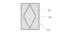
図5に示すように再帰性反射マーカ40は、開口44を有するカバー43をさらに有していていることが好ましい。開口44の形状は例えばひし形であり得るが、三角形や矩形であっても構わない。開口44の形状がそのまま、マーカ形状になる。換言すると、開口44の形状は、再帰性反射マーカ40に特定の反射パターンを与える。複数の再帰性反射材42を覆うようにカバー43を設けることにより、図6に示すように、複数の再帰性反射材42の輪郭は鋸歯状に乱れることはなく、その輪郭を開口44の形状にすることができる。図示する例では、ひし形の形状を有する開口44を含むカバー43を利用することにより、反射パターンの形状をひし形とすることができる。
As shown in FIG. 5, the
図7に示すように、カバー43を備えた再帰性反射マーカ40を用いることで、情報処理装置30はマーカ形状を的確に捉えることができる。その結果、フレーム画像において再帰性反射マーカ40の位置は正確に特定される。なお、フレーム画像において、隣接する2つの再帰性反射材42の間には、段差の影響により影(輝度が低い部分)が生じる可能性がある。ただし、再帰性反射材42の輝度が高いので、イメージセンサに投影される影の幅を抑えることで、影を目立たなくすることができる。
As illustrated in FIG. 7, by using the
なお、図2に示すように、再帰性反射材42を用いることにより、再帰性反射材42に入射した外乱光21aは、反射光21bとしてその入射方向に反射される。反射光21bは実質的にカメラ10に入射しないため、カメラ10によって撮影される動画像は外乱光の影響を受けにくくなる。
As shown in FIG. 2, by using the
計測システム100の全体の動作を概説すると以下のとおりである。
The overall operation of the
まず、観測者または被験者1が、被験者1の呼吸に伴う体動の発生位置に、特定の反射パターンの形状を有する再帰性反射マーカ40を配置する。光源20が赤外光で被験者1を照射すると、カメラ10は再帰性反射マーカ40で反射された赤外光を受けて、被験者1の動画像を撮影する。
First, the observer or the
例えば図8は、再帰性反射マーカ40を装着した被験者1を撮影したフレーム画像102を示す。画像中央部の高輝度領域(白い領域)104が、再帰性反射マーカ40からの反射光が検出された領域である。なお、所定のマーカ形状を有した再帰性反射マーカ40を用いた場合、その形状に対応した形状の高輝度領域が画像中に視認される。参考として、図9は、再帰性反射マーカ40を装着しない被験者を撮影したフレーム画像106を示す。再帰性反射マーカ40が存在しない場合には撮影されたフレーム画像内の輝度変化は非常に小さいと言える。図8および図9には、複数の縦線および横線が示されているが、これは画像処理のために仮想的に設けられた境界線である。本明細書では、境界線によって区画される画像の領域を、画像の「部分領域」と呼ぶ。図8には、部分領域Pが例示されている。なお、部分領域Pの境界線は理解の便宜のため強調して表示されている。
For example, FIG. 8 shows a
情報処理装置30は、図8に示されるような、動画像を構成する時系列の各複数のフレーム画像を解析して、複数のフレーム画像の輝度値の変化に基づいて被験者1の体動を検出する。より具体的に説明すると、情報処理装置30は、図8に示す高輝度領域104を複数のフレーム画像にわたって検出する。平静時の被験者1の体動は呼吸に起因して発生するため、高輝度領域104の位置が呼吸の周期に合わせて変化(振動)する。情報処理装置30は、高輝度領域104の振動の1周期を1呼吸周期として、所定期間にわたって呼吸周期の数をカウントすることにより、その期間における被験者1の呼吸数(bpm)を計測することができる。呼吸数(bpm)は60/呼吸周期(s)で表される。
The
本明細書においては、主として呼吸数を計測する例を説明する。しかしながら、呼吸数は被験者の呼吸に起因する生体活動の一例であり、被験者の呼吸に起因する他の生体活動を計測してもよい。本明細書では、被験者の呼吸動作を計測し、呼吸による体動から呼吸に起因する波形(呼吸波形に相当する波形)を導出する。典型的には、その波形を利用して評価可能な他の生体活動、たとえば、呼吸の深さ、乱れ、無呼吸期間、無呼吸期間が発生する頻度などの生体活動は、本明細書において、計測対象である生体活動の範疇である。 In this specification, an example in which the respiratory rate is mainly measured will be described. However, the respiratory rate is an example of a biological activity resulting from the subject's breathing, and other biological activities resulting from the subject's breathing may be measured. In this specification, a subject's breathing motion is measured, and a waveform resulting from breathing (a waveform corresponding to the breathing waveform) is derived from body motion due to breathing. Typically, other biological activities that can be evaluated using the waveform, for example, biological activities such as breathing depth, turbulence, apnea periods, frequency of occurrence of apnea periods, This is the category of the biological activity to be measured.
図10は、複数のフレーム画像の輝度値の変化に基づいて測定された、高輝度領域104の振動を示す。再帰性反射マーカ40を用いて観測される波形は暗い撮影環境下でも呼吸による体動を精度よく測定することが可能である。つまり、輝度値を利用して体動、すなわち呼吸を測定することが可能である。参考として、図11は、再帰性反射マーカを設けずに暗い撮影環境下で撮影された複数のフレーム画像の輝度値の変化を示す。再帰性反射マーカが存在しないことにより、画像内の輝度変化はもともと小さく、そのため複数のフレーム画像にわたって輝度値の変化を観測してもノイズの影響が非常に大きい。よって計測する必要がある体動の波形がノイズに埋もれている。なお、図10と図11では、縦軸のスケールは数倍程度異なっていることに留意されたい。理解の便宜のため、図11でのスケールは図10よりも大きくしている。換言すれば、再帰性反射マーカ40を用いる方(図10)が、用いない方(図11)よりも、信号対雑音比(SNR)に優れていることを意味する。
FIG. 10 shows the vibration of the high-
本実施の形態の計測方法によれば、再帰性反射マーカ40を利用することにより、赤外光の反射光量を十分確保して撮影を行うことができる。その結果、被験者1とカメラ10とを、たとえば6m程度離して設置することができる。また、計測する部屋を暗くすることができる。これにより、被験者1への圧迫感を軽減しつつ、観測場所の明るさの変化、室内光源の位置、外部からの入射光の有無の影響を受けにくい環境下、つまりノイズの影響が小さい環境下で撮影を行うことが可能になる。よって生体活動をより正確に計測することが可能になる。さらに、上述した側面が鋸歯状の再帰性反射マーカ40を利用することにより、再帰性反射材42に入射する光の入射角度を小さくすることが可能となり、再帰性反射材42の反射率を維持することができる。
According to the measurement method of the present embodiment, by using the
図12は、計測システム100の、主として情報処理装置30のハードウェア構成の例を示す。本実施の形態では、情報処理装置30はカメラ10、およびディスプレイ32と接続されている。情報処理装置30は、カメラ10から、撮影された動画像のデータを受け取る。またディスプレイ32は、処理の結果である、被験者1の生体活動である呼吸の数の計測結果を表示する。例えば、高輝度領域が検出されないことにより、カメラ10の撮影方向が適切でないと判断した場合には、情報処理装置30はディスプレイ32に警告を表示してもよい。
FIG. 12 shows an example of the hardware configuration of the
情報処理装置30は、CPU301と、ROM302と、RAM303と、ハードディスクドライブ(HDD)304と、インタフェース(I/F)305と、画像処理回路306とを有する。CPU301は情報処理装置30の動作を制御する。ROM302は、コンピュータプログラムを格納している。コンピュータプログラムは、たとえば後述するフローチャートによって示される処理をCPU301または画像処理回路306に行わせるための命令群である。RAM303は、CPU301による実行にあたって、コンピュータプログラムを展開するためのワークメモリである。HDD304は、カメラ10から受信した動画像のデータ、または計測された被験者1の呼吸数のデータを格納する記憶装置である。
The
I/F305は、情報処理装置30がカメラ10から動画像のデータを受け取るためのインタフェースである。情報処理装置30が有線のネットワーク経由で動画像のデータを受け取る場合には、I/F305はたとえばイーサネット(登録商標)端子である。情報処理装置30が無線のネットワーク経由で動画像のデータを受け取る場合には、I/F305はたとえばWi−Fi(登録商標)規格に準拠した通信を行う送受信回路である。またはI/F305は、有線の映像入力端子であってもよい。
The I /
画像処理回路306は、動画像のデータを解析する、いわゆるグラフィックスプロセッサである。画像処理回路306は、動画像の各フレーム画像の高輝度領域を検出し、高輝度領域の振動に基づいて体動を検出し、体動の振動波形に基づいて呼吸数をカウントする。
The
本実施の形態ではCPU301とは別に画像処理回路306を設けているが、これは一例である。例えば、CPU301と画像処理回路306とを統合した集積回路を用いてもよいし、後述する画像処理回路306の処理の一部を、CPU301が行ってもよい。
In this embodiment, the
図13は、計測システム100で行われる処理の手順の一例を示す。
FIG. 13 shows an example of a processing procedure performed in the
ステップS1において、カメラ10が、再帰性反射マーカ40が配置された被験者1を撮影する。撮影された動画像は情報処理装置30に送られる。
In step S1, the
ステップS2において、情報処理装置30の画像処理回路306は、撮影した動画像を構成する複数のフレーム画像の各々を、複数の部分領域に分割する。部分領域(たとえば図8の部分領域P)は、たとえば横64画素、縦64画素の大きさを有する。なお「分割する」とは、実際の動作として分割する必要はない。たとえば画像を切り出す単位または処理を行う単位として部分領域のサイズを設定する、という動作も、ここで言う「分割する」動作に含まれ得る。
In step S <b> 2, the
ステップS3において、画像処理回路306は、各部分領域の輝度値に基づいて、再帰性反射マーカ40が存在する部分領域、および生体反応による体動箇所を含む部分領域を特定する。より具体的に説明する。再帰性反射マーカ40が存在する部分領域は、各フレーム画像内で特定され得る。一方、体動箇所を含む部分領域は、複数のフレーム画像にわたって、すなわち複数のフレーム画像間で特定され得る。
In step S <b> 3, the
再帰性反射マーカ40が存在する部分領域は以下の処理によって特定される。たとえば、画像処理回路306は、再帰性反射マーカ40が存在する場合に観測される部分領域の輝度値の情報を、予めROM302に保持している。この情報を輝度値の閾値として利用し、閾値以上の輝度値を有する部分領域を、再帰性反射マーカ40が存在する部分領域として特定する。
The partial area where the
このときの輝度値は、部分領域に含まれる各画素の輝度値の積算値であってもよいし、平均値であってもよい。輝度値の積算値および平均値のいずれを採用するかに応じて、閾値もまた変化し得る。 The luminance value at this time may be an integrated value of the luminance values of the pixels included in the partial region, or may be an average value. Depending on whether the integrated value or the average value of the luminance values is adopted, the threshold value may also change.
一方、体動箇所を含む部分領域は以下の処理によって特定される。上述のように、再帰性反射マーカ40からの反射光が観測される領域は、生体反応(呼吸)による体動により変動する。いま、各フレーム画像に関して、ある共通の座標位置に存在する部分領域Qに着目する。図14(a)および(b)は、異なる時刻に撮影された2枚のフレーム画像における部分領域Qの例を示す。図14(a)および(b)に示す領域Rは、再帰性反射マーカ40からの反射光が検出されている高輝度領域であるとする。呼吸に伴う体動により、部分領域Qが、高輝度領域になったりならなかったりする。
On the other hand, the partial region including the body movement location is specified by the following process. As described above, the region where the reflected light from the
図14(c)は、このときの部分領域Qの輝度値の変化を示す。複数のフレーム画像にわたって時系列的に部分領域Qの輝度を観測すると、ある閾値Tを超えるフレーム画像群と、超えないフレーム画像群とが交互に存在する。 FIG. 14C shows a change in the luminance value of the partial region Q at this time. When the luminance of the partial area Q is observed in time series over a plurality of frame images, a group of frame images exceeding a certain threshold T and a group of frame images not exceeding exist alternately.
図13のステップS3において、体動箇所を含む部分領域は、図14(c)に示す輝度変化を示す座標位置の部分領域Qとして特定される。そして、部分領域Qに含まれる画素群を一まとまりとして、輝度値の演算(画像処理)が行われる。 In step S3 of FIG. 13, the partial area including the body movement location is specified as the partial area Q of the coordinate position indicating the luminance change shown in FIG. Then, a luminance value calculation (image processing) is performed with a group of pixels included in the partial region Q as a group.
ステップS4において、画像処理回路306は、体動箇所を含む部分領域Qの平均輝度値をフレーム画像毎に算出する。
In step S4, the
ステップS5において、画像処理回路306は、算出したフレーム画像毎の平均輝度値を利用して被験者の呼吸数をカウントする。算出した各平均輝度値は、図10に示す波形として表現される。画像処理回路306は、部分領域Qの平均輝度値が振動することによって特定される体動の1周期を1呼吸として、所定期間内の呼吸数をカウントする。
In step S5, the
以上の処理により、計測システム100において、高い精度で呼吸数の情報を取得することができる。傾斜した複数の再帰性反射材42を含む再帰性反射マーカ40から反射された赤外光の光量は、光源20から再帰性反射材42までの距離に依存せずに十分大きいので、カメラ10が撮影した動画像を用いると、画像内の再帰性反射マーカ40から呼吸による体動を含む部分領域を特定することは容易である。
Through the above process, the
上述したとおり、再帰性反射マーカ40がカバー43を含んでいる場合、再帰性反射マーカ40は特定の反射パターン(例えば、ひし形)を有したマーカとして機能する。反射パターンは、図8に示すように、フレーム画像において高輝度領域として確認される。画像処理回路306は、カメラ10から動画像を受け取り、例えば公知のパターン認識手法を用いて、各フレーム画像における再帰性反射マーカ40の座標位置を特定してもよい。その座標位置は、例えば図6に示される反射パターン(ひし形)の各頂点や重心の座標を意味する。例えば、パターンマッチング処理によって、フレーム画像中の反射パターンを特定することができる。画像処理回路306は、予め、特定の反射パターンを有する再帰性反射マーカ40が用いられること、およびその反射パターンの特徴を示す情報(例えば、テンプレート)を、たとえばROM302に保持している。画像処理回路306は、その反射パターンの特徴を利用して各フレーム画像にパターンマッチング処理を行い、再帰性反射マーカ40の座標位置を特定することができる。反射パターンを利用してより確実かつより簡易に高輝度領域を検出することができる。
As described above, when the
反射パターンはエッジ情報を含んでいるので、そのエッジ情報を積極的に利用して、フレーム画像における再帰性反射マーカ40の座標位置を特定することもできる。具体的に説明すると、画像処理回路306は、コーナ検出法およびエッジ検出法を用いて再帰性反射マーカ40の座標位置を特定してもよい。このような特定方法は、本出願人による未公開の特許出願である特願2015−102726号に記載されている。これらの開示内容の全てを参考のために本明細書に援用する。
Since the reflection pattern includes edge information, the coordinate position of the
画像処理回路306は、上述した、パターンマッチング処理およびエッジ情報を利用した処理によって特定された再帰性反射マーカ40の座標位置に基づいて部分領域(図8を参照)を指定することができる。部分領域は、体動に伴う輝度値の変化を監視するための領域であり、体動箇所を含むように設定され得る。画像処理回路306は各フレーム画像を2つ以上に分割する。このとき、画像処理回路306は反射パターンを跨ぐ位置に境界線を設定する。さらに、境界線は、体動方向とは異なる方向に設定される。たとえばフレーム画像内で体動が上下方向に認められるとする。このとき画像処理回路306は、たとえば水平方向に境界線を設定して各フレーム画像を2つ以上に分割し、部分領域を設定する。
The
部分領域の設定の一例を具体的に説明する。画像処理回路306は反射パターンに対応した高反射領域のエッジを含む部分領域を特定する。その部分領域のサイズは、上述したように例えば横64画素、縦64画素であり得る。例えば画像処理回路306は、コーナ検出の結果から反射パターンのエッジ情報を得ることができる。そして、画像処理回路306は、反射パターンのエッジを含む領域を部分領域として指定する。換言すると、画像処理回路306は、そのエッジを跨ぐように部分領域を設定する。ここで言うエッジとは、変動方向に関して対向する複数のエッジが存在する場合にはその一方のエッジを指す。
An example of setting the partial area will be specifically described. The
画像処理回路306は部分領域を特定した後、部分領域の平均輝度値をフレーム画像毎に算出する。換言すると、画像処理回路306は、フレーム画像毎の輝度値に基づいて呼吸波形を生成する。画像処理回路306は、算出したフレーム画像毎の平均輝度値(呼吸波形)を利用して被験者の呼吸数をカウントすればよい。
After specifying the partial area, the
〔カメラ10の変形例〕
図15は、可視光領域の波長を遮る光学フィルタ11を装着したカメラ10を示す。この光学フィルタ11は、一般に赤外フィルタとも呼ばれる。
[Modification of Camera 10]
FIG. 15 shows the
カメラ10は光学フィルタ11をさらに備えていてもよい。光学フィルタ11は、光源20から放射され、再帰性反射マーカ40において反射された赤外光は透過するが、可視光は遮断する。光学フィルタ11を設けることにより、赤外光以外の光、より具体的には可視光、がカメラ10に入射することを防ぎ、それにより、撮影された動画像の輝度値の変化への影響を低減できる。可視光に起因する各フレーム画像の輝度値の変動を抑制できるため、可視光のみに起因し、生体反応に起因しない外乱ノイズの発生を低減できる。
The
本願発明者は、可視光領域の波長を遮る光学フィルタ11を設けることは非常に有用であると考えている。その理由は、実際の撮影時には、完全な暗室環境を実現することが困難な場合が多いからである。たとえば病院で生体活動計測システム100を動作させる場合には、夜間であったとしても常夜灯、避難誘導灯などが院内に点灯する。そのような撮影環境では光学フィルタ11によって可視光を遮断することが好適である。
The inventor of the present application considers that it is very useful to provide the
さらに、図15に示す光学フィルタ11として、可視光のみならず不要な赤外光をも遮断する光学フィルタを設けてもよい。換言すれば、光学フィルタ11として、光源20が放射する赤外光を通過させるバンドパスフィルタを設けてもよい。
Furthermore, an optical filter that blocks not only visible light but also unnecessary infrared light may be provided as the
まず、光源20として急峻な波長特性を有するLED光源を採用する。波長は、たとえば850nmまたは940nm、およびそれらの近傍である。「急峻な波長特性」とは、ここでは放射される赤外光の波長の変動が小さいことを意味する。
First, an LED light source having a steep wavelength characteristic is adopted as the
光源20に対応させて、光学フィルタ11として、光源20から放射される赤外光を通過させるバンドパス特性を有する光学フィルタをカメラ10に設ける。たとえば、光源20から放射される赤外光の波長が850nmの場合には、850nmの波長の赤外光を透過させる光学フィルタ11を設ける。
In correspondence with the
光源20の波長と、光学フィルタ11の通過帯域とを一致させることにより、カメラ10は、光源20から放射される赤外光の波長と同じ波長の光のみに感度を持つことになる。可視光のみならず、不要な赤外光をも遮断できるため、撮影された動画像は外乱光の影響を受けない。なお、再帰性反射マーカ40を利用しているため、光源20から放射され、再帰性反射材40で反射された赤外光の光量は大きい。よって、反射光の捉え易さは先に説明した態様と同じである。
By matching the wavelength of the
本願発明者は、光学フィルタ11を有したカメラ10と、白色光源および赤外線光源と、を用いて、再帰性反射材の反射性能を計測した。再帰性反射材の反射性能(単位:cd/lx/m2)の計測結果を下記の表1に示す。
The inventor of the present application measured the reflection performance of the retroreflecting material using the

再帰性反射材に入射する光の入射角度が大きくなると、再帰性反射材の反射性能が低下することが分かる。入射角度が5°から30°に変わると、反射性能は半分以下になることが分かる。反射性能の低下は、撮影時の輝度の低下に繋がる。本実施の形態による再帰性反射マーカ40を用いることにより、撮影時の輝度の低下を抑止することができる。
It can be seen that when the incident angle of light incident on the retroreflective material increases, the reflective performance of the retroreflective material decreases. It can be seen that when the incident angle is changed from 5 ° to 30 °, the reflection performance becomes less than half. A decrease in reflection performance leads to a decrease in luminance during photographing. By using the
(実施の形態2)
図16は、実施の形態1によるカバー44を含む再帰性反射マーカ40を用いた場合のフレーム画像中の反射パターン領域の輝度分布を模式的に示している。
(Embodiment 2)
FIG. 16 schematically shows the luminance distribution of the reflection pattern area in the frame image when the
実施の形態1では、再帰性反射材42の傾斜角度は全て等しい。その場合、カメラ10の設置位置が非常に低いと、図16に示すように、再帰性反射マーカ40に入射する光の入射角度は全体的に大きく、再帰性反射材42(つまり、反射パターン)の領域のうち、カメラ10からより離れた領域では、入射角度は一層大きくなることが想定される。実施の形態1による再帰性反射マーカ40は、反射パターンの高輝度領域において均一な輝度を確保するという点で、使用される計測システムによっては若干不十分であるかもしれない。
In the first embodiment, the inclination angles of the
本実施の形態による再帰性反射材42においては、カメラ10から遠ざかるにつれて段階的にまたは徐々に傾斜角度が大きくなるように複数の再帰性反射材42を配置するように工夫している。以下、本実施の形態による再帰性反射マーカ40Aの構造を中心に説明する。
In the
図17は、本実施の形態による再帰性反射マーカ40Aの斜視図である。再帰性反射マーカ40Aは、ベース41と、複数の再帰性反射材42とを有する。実施の形態1と同様に、再帰性反射マーカ40Aは、開口を含むカバー43をさらに有していても構わない。再帰性反射マーカ40Aにおいては、複数の再帰性反射材42の各々の傾斜角度は、光源20に近い側から遠ざかるにつれて徐々にまたは段階的に大きくなる。具体的に説明すると、再帰性反射マーカ40Aは、実施の形態1と同様に、Z方向から見たとき、鋸歯状の構造を有している。再帰性反射材42(つまり、鋸歯)の高さhは全て等しく、かつ、図17に示すように、光源に最も近い再帰性反射材42を支持するベース41のY方向における長さをdとし、残りの再帰性反射材42を支持するベース41のY方向における長さをそれぞれc、bおよびaとすると、a<b<c<dが満足される。この幾何学的関係により、光源20に最も近い再帰性反射材42の傾斜角度が最も小さくなり、光源20から最も離れた再帰性反射材42の傾斜角度は最も大きくなる。長さa、b、cおよびdは、この順番で段階的または徐々に短くなるように設定され得る。換言すると、鋸歯のピッチは、光源20に近い側から遠ざかるにつれて段階的または徐々に小さくなる。具体的に説明すると、長さa、b、cおよびdの比が、それぞれの再帰性反射材42に入射する光の入射角度が略一致するように決定される。
FIG. 17 is a perspective view of a
図18を参照して、2つの再帰性反射材42を含む再帰性反射マーカ40を例に、再帰性反射材42のY方向における長さの比を具体的に説明する。
With reference to FIG. 18, the ratio of the lengths of the
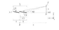
図18は、カメラ10(または光源20)と2つの再帰性反射材42との位置関係を模式的に示す。図中の点OをXYZ座標系の原点とする。カメラ10の位置を示す点CはX軸上に位置し、傾斜した再帰性反射材42の一端はY軸上に位置している。Lは、再帰性反射マーカ40のY軸方向の長さであり、hは再帰性反射材42のX軸方向の長さ、つまり、再帰性反射マーカ40の高さである。xは、X軸上において再帰性反射マーカ40の高さhの半分の位置(h/2)から点Cまでの距離であり、点Cの座標は、(h/2+x、0)である。yは、Y軸において原点Oから再帰性反射マーカ40の中心点までの距離である。その中心点は、再帰性反射マーカ40のカメラ10側の端から長さがL/2となる点に相当する。その中心点の座標は、(h/2、y)で表すことができる。
FIG. 18 schematically shows the positional relationship between the camera 10 (or the light source 20) and the two
βは、カメラ10側の再帰性反射材42のY軸方向の長さbと長さL/2との差を指している。従って、長さbは、L/2+βで表すことができ、カメラ10とは反対側の再帰性反射材42のY軸方向の長さaは、L/2−βで表すことができる。点Pは、カメラ側の再帰性反射材42の中心点を指し、その座標は、(h/2、y−L/4)で表すことができる。点Qは、カメラ10とは反対側の再帰性反射材42の中心点を指し、その座標は、(h/2、y+L/4)で表すことができる。
β indicates the difference between the length b in the Y-axis direction and the length L / 2 of the
ここで、y>>x、かつ、L>>hであると仮定し、点Pおよび点Qへの入射角度が等しくなるβを求める。ここで、上述した「再帰性反射材42に入射する光の入射角度が略一致する」とは、具体的には「再帰性反射材42の中心点に入射する光の入射角度が、複数の再帰性反射材42の間で略一致する」ことを意味する。∠QCPは式(1)で求めることができる。
∠QCP=tan-1(y/(x−L/4))−tan-1(y/(x+L/4)) 式(1)
Here, assuming that y >> x and L >> h, β at which the incident angles to the point P and the point Q are equal is obtained. Here, the above-described “incident angles of light incident on the
∠QCP = tan −1 (y / (x−L / 4)) − tan −1 (y / (x + L / 4)) Equation (1)
∠QCPは、カメラ10側の再帰性反射材42と、カメラ10とは反対側の再帰性反射材42との角度差にも相当するので、∠QCPは、式(2)によっても表すことができる。
∠QCP=tan-1(h/(L/2−β))+tan-1(h/(L/2+β)) 式(2)
∠QCP corresponds to the angle difference between the retroreflecting
QCP = tan −1 (h / (L / 2−β)) + tan −1 (h / (L / 2 + β)) Equation (2)
atan(θ)は、θが小さいとき、atan(θ)≒θと近似することがでるので、式(1)および(2)から、式(3)が得られる。
y/(x−L/4)−y/(x+L/4)=h/(L/2−β)+h/(L/2+β) 式(3)
Since atan (θ) can be approximated as atan (θ) ≈θ when θ is small, Equation (3) is obtained from Equations (1) and (2).
y / (x−L / 4) −y / (x + L / 4) = h / (L / 2−β) + h / (L / 2 + β) Equation (3)
式(3)をさらに変形すると、式(4)が得られる。
yL/(x2−L2/16)=4βh/(L2/4−β2) 式(4)
Further transforming equation (3) yields equation (4).
yL / (x 2 -L 2/ 16) = 4βh / (
x2>>L2/16、かつ、L2/4>>β2が成立するので、式(4)は、式(5)に近似されて、最終的に、式(6)が導出される。
yL/x2=4βh/(L2/4) 式(5)
β=yL3/16x2 式(6)
x 2 >> L 2/16, and, since L 2/4 >> β 2 is satisfied, the formula (4) is approximated to equation (5), and finally, the equation (6) is derived The
yL / x 2 = 4βh / (
β = yL 3 / 16x 2 formula (6)
上記では2つの再帰性反射材42が含まれる例を示したが、βはn個の再帰性反射材42が含まれる場合にも拡張することができて、隣接する2つの再帰性反射材42のY方向の長さの差βnは式(7)によって一般化される。再帰性反射材42のY方向における長さの比をβnを用いて決定することができる。
βn=yL3/(2n3x2) 式(7)
Although an example in which two
β n = yL 3 / (2n 3 x 2 ) Formula (7)
本実施の形態による再帰性反射マーカ40Aを用いることにより、光源20から離れて位置した再帰性反射材42に入射する光の入射角度を小さくすることが可能となり、反射パターン領域の全体において輝度を確保することができる。
By using the
(実施の形態3)
図19は、実施の形態2によるカバー44を含む再帰性反射マーカ40Aを用いた場合のフレーム画像中の反射パターン領域の輝度分布を模式的に示している。
(Embodiment 3)
FIG. 19 schematically shows the luminance distribution of the reflection pattern area in the frame image when the
実施の形態2では、再帰性反射材42の傾斜角度をカメラ10から遠ざかるにつれて大きくなるように設定することで、反射パターン領域の全体において輝度を確保している。ただし、傾斜角度は、隣接した2つの再帰性反射材42の間の境界、つまり、段差の位置で変わるので、図示するように、反射パターン領域の一部、つまり、各境界近傍において輝度差が生じ得る。
In the second embodiment, the brightness of the entire reflection pattern area is ensured by setting the inclination angle of the
本実施の形態においてはこれを考慮して、再帰性反射材の形状を工夫している。具体的に説明すると、本実施の形態による再帰性反射材は曲面形状の反射面を有している。曲面によって、段差近傍で発生し得る輝度差を抑制することができる。以下、本実施の形態による再帰性反射マーカ40Bの構造を中心に説明する。
In the present embodiment, the shape of the retroreflecting material is devised in consideration of this. More specifically, the retroreflecting material according to the present embodiment has a curved reflecting surface. The curved surface can suppress a luminance difference that may occur near the step. Hereinafter, the structure of the
図20は、本実施の形態による再帰性反射マーカ40Bの斜視図である。図21は、隣接した2つの再帰性反射材42の間の境界近傍に入射した光線の様子を模式的に示す。
FIG. 20 is a perspective view of a
再帰性反射マーカ40Bは、ベース41と、複数の再帰性反射材42とを有する。複数の再帰性反射材42は、曲面形状の複数の反射面42Sを有している。換言すると、各々が曲面形状の反射面42Sを有している。曲面の形状は、隣接する2つの再帰性反射材の曲面上の任意の点における法線に対する光の入射角度が全て等しくなる放物線によって規定される凹面鏡の形状に等しくなる。実施の形態1と同様に、再帰性反射マーカ40Bは、開口を含むカバー43をさらに有していても構わない。
The
図20のZ方向から見た再帰性反射マーカ40Bの側面は、複数の反射面42Sに対応した複数の鋸歯を含む鋸歯状の構造を含んでいる。XY平面に平行な面で切断した再帰性反射マーカ40の断面はいずれも、側面の形状と同一の鋸歯状の構造を含む。
The side surface of the
このような構成によると、図21に示すように、隣接した2つの再帰性反射材42の間の境界近傍において、一方の再帰性反射材42に入射する光の入射角度α1と、他方の再帰性反射材42に入射する光の入射角度α2との差を小さくすることができる。その結果、隣接する2つの再帰性反射材42における反射光の反射角度を略等しくすることができるので、反射マーカ領域の各境界近傍において輝度差を小さくすることができる。
According to such a configuration, as shown in FIG. 21, in the vicinity of the boundary between two adjacent
図22を参照して、再帰性反射材42の曲面形状を具体的に説明する。
With reference to FIG. 22, the curved surface shape of the
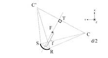
図22は、凹面鏡、凹面鏡の焦点、物点および像点を模式的に示す。XY平面における反射面42Sの断面形状は、図22に示す凹面鏡の形状に一致する。点C(カメラ位置)は物点を示し、点C’は点Cから出た光線が集光されて実像が形成される点(像点)を示し、Fは凹面鏡の焦点を示し、fは凹面鏡の焦点距離を示している。点Rは、再帰性反射材42のカメラ側の端に対応した凹面鏡上の点に相当し、点Sは、再帰性反射材42のカメラ側と反対側の端に対応した凹面鏡上の点に相当する。また、点Tは、線分SRの垂直二等分線と線分CC’との交点を示している。
FIG. 22 schematically shows the concave mirror, the focal point, the object point, and the image point of the concave mirror. The cross-sectional shape of the reflecting surface 42S in the XY plane matches the shape of the concave mirror shown in FIG. Point C (camera position) indicates an object point, point C ′ indicates a point (image point) where a light beam emitted from point C is collected to form a real image, F indicates a focal point of the concave mirror, and f indicates The focal length of the concave mirror is shown. Point R corresponds to a point on the concave mirror corresponding to the end of the
上述した凹面鏡においては、点Cからの光線は、凹面鏡によって点C’に集光される。焦点Fは線分SRの垂直二等分線上に位置し、かつ、線分SRの垂直二等分線と線分CC’とは点Tで直交し、かつ、点Tが線分CC’の中点に一致し、かつ、線分SRと線分CC’との距離が、焦点距離fの2倍(2f)に等しくなる。換言すると、線分SRの中点と点Tとを結ぶ線分の長さは、2fである。 In the concave mirror described above, the light beam from the point C is collected at the point C ′ by the concave mirror. The focal point F is located on the vertical bisector of the line segment SR, the vertical bisector of the line segment SR and the line segment CC ′ are perpendicular to each other at the point T, and the point T is the line segment CC ′. It coincides with the midpoint, and the distance between the line segment SR and the line segment CC ′ is equal to twice the focal length f (2f). In other words, the length of the line segment connecting the midpoint of the line segment SR and the point T is 2f.
本実施の形態による再帰性反射材42の曲面形状は、点Tが線分CC’の中点に一致する放物線によって決定される。この条件下では、点Cからの光線の入射角度は凹面鏡上で一定となる。そのため、複数の反射面42Sの任意の点における法線に対する光の入射角度を全て等しくすることができる。
The curved surface shape of the
実施の形態1から3では、再帰性反射マーカを利用した計測システムを主に説明した。ただし、本発明による他の実施の形態は、支持面に対して傾斜した複数の反射材から構成された反射マーカを利用した計測システムであり得る。反射材の傾斜角度が十分に大きい場合、例えば90°に近い角度であるような場合、反射材に入射する光の入射角度を十分に小さくすることが可能となる。その場合、再帰性反射材を用いなくても、被験者からの十分な反射光量を確保できる。このように、図18に示す、反射材の傾斜角度およびカメラと反射マーカとの位置関係によっては、単純な反射マーカを利用することも可能である。
In
本明細書は、以下の項目に記載の被験体の呼吸に起因する生体活動の計測システムを開示している。 The present specification discloses a measurement system for life activity resulting from respiration of a subject described in the following items.
〔項目1〕
光を放射する光源と、
前記光を受けて動画像を生成する撮像装置と、
前記動画像を利用して被験体の生体活動を計測する画像処理回路と
を備える計測システムであって、
前記被験体の呼吸に伴う体動の発生位置に反射マーカが配置され、前記光源から、前記被験体に向けて前記光が放射されたときにおいて、
前記撮像装置は、前記反射マーカで反射された前記光を複数の時刻において受けて、時系列の複数のフレーム画像から構成される前記動画像を生成し、
前記画像処理回路は、前記撮像装置から前記動画像を受け取り、前記複数のフレーム画像の輝度値の変化に基づいて前記被験体の呼吸に起因する生体活動を計測し、
前記反射マーカは、支持面を有するベースと、各々が前記支持面に対して傾斜し、前記支持面で支持された複数の反射材と、を有する、計測システム。
[Item 1]
A light source that emits light;
An imaging device that receives the light and generates a moving image;
An image processing circuit for measuring a subject's biological activity using the moving image, and a measurement system comprising:
When a reflection marker is arranged at a position where a body movement accompanying breathing of the subject is performed, and the light is emitted from the light source toward the subject,
The imaging device receives the light reflected by the reflective marker at a plurality of times, generates the moving image composed of a plurality of time-series frame images,
The image processing circuit receives the moving image from the imaging device, measures a biological activity caused by breathing of the subject based on a change in luminance value of the plurality of frame images,
The reflective marker includes a base having a support surface, and a plurality of reflectors each inclined with respect to the support surface and supported by the support surface.
項目1に記載の計測システムによると、生体活動の計測条件が周囲の環境の影響を受けにくい、呼吸に起因する生体活動の計測システムが提供される。
According to the measurement system described in
〔項目2〕
前記反射マーカは再帰性反射マーカであり、前記複数の反射材は複数の再帰性反射材である、項目1に記載の計測システム。
[Item 2]
The measurement system according to
項目2に記載の計測システムによると、光源と再帰性反射マーカとを組み合わせて使用するため、周囲が暗い場合でも明るい場合でも、かつ被験体と撮像装置との距離を十分離したとしても、呼吸等の生体活動に起因する体動を、複数のフレーム画像の変化から捉えることができる。特に、傾斜した複数の再帰性反射材を含む再帰性反射マーカを用いることにより、複数のフレーム画像中の再帰性反射マーカの領域において輝度を維持することができる。
According to the measurement system described in
〔項目3〕
前記反射マーカが前記被験体の呼吸に伴う体動の発生位置に配置されたときにおいて、
前記複数の反射材の各々の傾斜角度は前記光源に近い側から遠ざかるにつれて大きくなる、項目1または2に記載の計測システム。
[Item 3]
When the reflective marker is disposed at a position where body movement accompanying breathing of the subject occurs,
Item 3. The measurement system according to
項目3に記載の計測システムによると、光源から離れて位置した反射材に入射する光の入射角度を小さくすることが可能となり、反射パターン領域の全体において輝度を確保することができる。 According to the measurement system described in Item 3, it is possible to reduce the incident angle of the light incident on the reflective material located away from the light source, and the luminance can be ensured in the entire reflection pattern region.
〔項目4〕
前記反射マーカの側面は、前記複数の反射材に対応した複数の鋸歯を含む鋸歯状の構造を含み、前記複数の鋸歯の各々の高さは等しく、
前記反射マーカが前記被験体の呼吸に伴う体動の発生位置に配置されたときにおいて、鋸歯のピッチは、前記光源に近い側から遠ざかるにつれて小さくなる、項目3に記載の計測システム。
[Item 4]
The side surface of the reflective marker includes a sawtooth structure including a plurality of saw teeth corresponding to the plurality of reflectors, and each of the plurality of saw teeth has an equal height,
項目4に記載の計測システムによると、光源に最も近い反射材の傾斜角度を最も小さくし、光源から最も離れた反射材の傾斜角度を最も大きくすることができる。
According to the measurement system described in
〔項目5〕
前記複数の反射材の各々は、曲面形状の反射面を有している、項目4に記載の計測システム。
[Item 5]
Item 5. The measurement system according to
項目5に記載の計測システムによると、隣接する2つの反射材の段差近傍で発生し得る輝度差を抑制することができる。 According to the measurement system described in Item 5, it is possible to suppress a luminance difference that may occur in the vicinity of a step between two adjacent reflectors.
〔項目6〕
前記曲面形状は、隣接する2つの反射材の曲面上の任意の点における法線に対する前記光の入射角度が全て等しくなる放物線によって規定される凹面鏡の形状に等しく、
前記複数の反射材の配列方向に平行な第1の方向に直交し、各反射材が延伸する第2の方向および前記第1の方向の両方に直交する第3の方向と、前記第1の方向と、にそれぞれ平行な面で切断した、前記各反射材の曲面の断面において、前記各反射材の前記撮像装置側の第1の端に位置する曲面上の点を点Rとし、前記各反射材の前記撮像装置とは反対側の第2の端に位置する曲面上の点を点Sとし、前記凹面鏡の焦点距離をfとし、物点を点Cとし、像点を点C’とすると、線分RSの垂直二等分線は、線分CC’の中点で前記線分CC’と直交し、かつ、前記凹面鏡の焦点は前記線分RSの垂直二等分線上に位置し、かつ、前記線分RSと前記線分CC’との距離が2fの長さである、項目5に記載の計測システム。
[Item 6]
The curved surface shape is equal to the shape of a concave mirror defined by a parabola in which the incident angles of the light with respect to the normal at any point on the curved surface of two adjacent reflectors are all equal,
A third direction orthogonal to a first direction parallel to an arrangement direction of the plurality of reflective materials, each of the second direction in which each reflective material extends, and a third direction orthogonal to both the first directions, and the first In the cross-section of the curved surface of each of the reflecting materials cut by a plane parallel to each direction, a point on the curved surface located at the first end of each reflecting material on the imaging device side is a point R, A point on the curved surface located at the second end of the reflector opposite to the imaging device is a point S, a focal length of the concave mirror is f, an object point is a point C, and an image point is a point C ′. Then, the perpendicular bisector of the line segment RS is orthogonal to the line segment CC ′ at the midpoint of the line segment CC ′, and the focal point of the concave mirror is located on the vertical bisector of the line segment RS. And the measurement system of item 5 whose distance of said line segment RS and said line segment CC 'is the length of 2f.
項目6に記載の計測システムによると、隣接する2つの反射材の段差近傍で発生し得る輝度差を抑制することができる。 According to the measurement system described in item 6, it is possible to suppress a luminance difference that may occur in the vicinity of a step between two adjacent reflectors.
〔項目7〕
前記反射マーカは、所定のマーカ形状を有した開口を含むカバーをさらに有し、
平面視において、前記複数の反射材の形状は、前記所定のマーカ形状に一致する、項目1から6のいずれかに記載の計測システム。
[Item 7]
The reflective marker further includes a cover including an opening having a predetermined marker shape,
7. The measurement system according to any one of
項目7に記載の計測システムによると、画像中のマーカ形状を的確に捉えることができる。 According to the measurement system described in Item 7, the marker shape in the image can be accurately captured.
〔項目8〕
前記所定のマーカ形状は、三角形、ひし形または矩形である、項目7に記載の計測システム。
[Item 8]
Item 8. The measurement system according to Item 7, wherein the predetermined marker shape is a triangle, a diamond, or a rectangle.
項目8に記載の計測システムによると、マーカ形状のバリエーションが提供される。 According to the measurement system according to item 8, variations in marker shape are provided.
〔項目9〕
前記画像処理回路は、各フレーム画像を複数の部分領域に分割し、前記複数の部分領域の輝度値の変化に基づいて前記被験体の呼吸に起因する生体活動を計測する、項目1から8のいずれかに記載の計測システム。
[Item 9]
The image processing circuit divides each frame image into a plurality of partial areas, and measures a biological activity caused by respiration of the subject based on a change in luminance values of the plurality of partial areas. A measurement system according to any one of the above.
項目9に記載の計測システムによると、処理単位として部分領域を利用することで演算処理の効率化が図れる。 According to the measurement system described in item 9, the efficiency of arithmetic processing can be improved by using a partial area as a processing unit.
〔項目10〕
前記光源は、赤外光線を放射する赤外線光源であり、
前記撮像装置は、可視光領域の波長を遮る光学フィルタを含む、項目1から9のいずれかに記載の計測システム。
[Item 10]
The light source is an infrared light source that emits infrared light,
10. The measurement system according to any one of
項目10に記載の計測システムによると、可視光のみに起因し、生体反応に起因しない外乱ノイズの発生を低減できる。
According to the measurement system described in
本発明は、被験体を撮影した動画像を解析して、被験体の生体活動、特に呼吸の数を非接触で計測する計測システムとして利用することができる。 INDUSTRIAL APPLICABILITY The present invention can be used as a measurement system that analyzes a moving image obtained by photographing a subject and measures a subject's life activity, particularly the number of breaths, in a non-contact manner.
1 被験者
10 カメラ
20 光源
30 情報処理装置
32 ディスプレイ
40、40A、40B 再帰性反射マーカ
41 ベース
42 再帰性反射材
42S 曲面
43 カバー
44 開口
100 計測システム
301 CPU
302 ROM
303 RAM
304 HDD
305 I/F
306 画像処理回路
DESCRIPTION OF
302 ROM
303 RAM
304 HDD
305 I / F
306 Image processing circuit
本発明の実施形態による計測システムは、光を放射する光源と、前記光を受けて動画像を生成する撮像装置と、前記動画像を利用して被験体の生体活動を計測する画像処理回路とを備える計測システムであって、前記被験体の呼吸に伴う体動の発生位置に反射マーカが配置され、前記光源から、前記被験体に向けて前記光が放射されたときにおいて、前記撮像装置は、前記反射マーカで反射された前記光を複数の時刻において受けて、時系列の複数のフレーム画像から構成される前記動画像を生成し、前記画像処理回路は、前記撮像装置から前記動画像を受け取り、前記複数のフレーム画像の輝度値の変化に基づいて前記被験体の呼吸に起因する生体活動を計測し、前記反射マーカは、支持面を有するベースと、各々が前記支持面に対して傾斜し、前記支持面で支持された複数の反射材と、所定のマーカ形状を有した開口を含むカバーをさらに有し、平面視において、前記複数の反射材の形状は、前記所定のマーカ形状に一致する。 A measurement system according to an embodiment of the present invention includes a light source that emits light, an imaging device that receives the light and generates a moving image, and an image processing circuit that measures a biological activity of a subject using the moving image. A reflection marker is disposed at a position where body movement occurs due to breathing of the subject, and when the light is emitted from the light source toward the subject, the imaging device is Receiving the light reflected by the reflective marker at a plurality of times, generating the moving image composed of a plurality of time-series frame images, and the image processing circuit receiving the moving image from the imaging device. Receiving and measuring a biological activity caused by respiration of the subject based on a change in luminance values of the plurality of frame images, and the reflective marker includes a base having a support surface and each of which is inclined with respect to the support surface. And, wherein the support surface a plurality of reflective material supported by, further comprising a cover including an opening having a predetermined marker shape, in plan view, the shape of the plurality of reflective material, to the predetermined marker shape Match .
ある実施形態において、前記反射面を前記反射マーカの側面に平行な面で切断した第1断面の形状は凹面鏡の第2断面の形状に一致し、前記反射マーカを前記平行な面で切断した第3断面はいずれも、前記反射マーカの側面の形状と同一であることを特徴とする。 In one embodiment, the shape of the first cross section obtained by cutting the reflective surface by a plane parallel to the side surface of the reflective marker matches the shape of the second cross section of the concave mirror, and the first shape obtained by cutting the reflective marker by the parallel surface is used. All three cross sections have the same shape as the side surface of the reflective marker .
ある実施形態において、前記凹面鏡においては、前記凹面鏡の焦点は、前記光源側の前記凹面鏡の前記第2断面における第1端点と前記光源とは反対側の前記凹面鏡の前記第2断面における第2端点とを結ぶ第1線分の垂直二等分線上に位置し、前記垂直二等分線は、前記光源と前記光源から放射された光が前記凹面鏡で集光されて実像が形成される像点とを結ぶ第2線分の中点で直交し、かつ、前記第1線分と前記第2線分の距離は、前記凹面鏡の焦点距離の2倍の距離に等しくなることを特徴とする。 In one embodiment, in the concave mirror, the focal point of the concave mirror is a first end point in the second cross section of the concave mirror on the light source side and a second end point in the second cross section of the concave mirror on the side opposite to the light source. The vertical bisector is an image point where the light emitted from the light source and the light source is condensed by the concave mirror to form a real image. And the distance between the first line segment and the second line segment is equal to twice the focal length of the concave mirror .
図20のZ方向から見た再帰性反射マーカ40Bの側面は、複数の反射面42Sに対応した複数の鋸歯を含む鋸歯状の構造を含んでいる。XY平面に平行な面で切断した再帰性反射マーカ40Bの断面はいずれも、側面の形状と同一の鋸歯状の構造を含む。
The side surface of the
〔項目1〕
光を放射する光源と、
前記光を受けて動画像を生成する撮像装置と、
前記動画像を利用して被験体の生体活動を計測する画像処理回路と
を備える計測システムであって、
前記被験体の呼吸に伴う体動の発生位置に反射マーカが配置され、前記光源から、前記被験体に向けて前記光が放射されたときにおいて、
前記撮像装置は、前記反射マーカで反射された前記光を複数の時刻において受けて、時系列の複数のフレーム画像から構成される前記動画像を生成し、
前記画像処理回路は、前記撮像装置から前記動画像を受け取り、前記複数のフレーム画像の輝度値の変化に基づいて前記被験体の呼吸に起因する生体活動を計測し、
前記反射マーカは、支持面を有するベースと、各々が前記支持面に対して傾斜し、前記支持面で支持された複数の反射材と、所定のマーカ形状を有した開口を含むカバーをさらに有し、
平面視において、前記複数の反射材の形状は、前記所定のマーカ形状に一致する、計測システム。
[Item 1]
A light source that emits light;
An imaging device that receives the light and generates a moving image;
An image processing circuit for measuring a subject's biological activity using the moving image, and a measurement system comprising:
When a reflection marker is arranged at a position where a body movement accompanying breathing of the subject is performed, and the light is emitted from the light source toward the subject,
The imaging device receives the light reflected by the reflective marker at a plurality of times, generates the moving image composed of a plurality of time-series frame images,
The image processing circuit receives the moving image from the imaging device, measures a biological activity caused by breathing of the subject based on a change in luminance value of the plurality of frame images,
The reflective marker further includes a base having a support surface, a plurality of reflectors each inclined with respect to the support surface and supported by the support surface, and a cover including an opening having a predetermined marker shape. And
In a plan view, the shape of the plurality of reflectors is a measurement system that matches the predetermined marker shape .
項目1に記載の計測システムによると、生体活動の計測条件が周囲の環境の影響を受けにくい、呼吸に起因する生体活動の計測システムが提供される。
また、項目1に記載の計測システムによると、画像中のマーカ形状を的確に捉えることができる。
According to the measurement system described in
Moreover, according to the measurement system described in
〔項目6〕
前記反射面を前記反射マーカの側面に平行な面で切断した第1断面の形状は凹面鏡の第2断面の形状に一致し、
前記反射マーカを前記平行な面で切断した第3断面はいずれも、前記反射マーカの側面の形状と同一であることを特徴とする、項目5に記載の計測システム。
[Item 6]
The shape of the first cross section obtained by cutting the reflective surface with a plane parallel to the side surface of the reflective marker matches the shape of the second cross section of the concave mirror,
Item 6. The measurement system according to Item 5 , wherein any of the third cross sections obtained by cutting the reflective marker along the parallel plane has the same shape as the side surface of the reflective marker .
項目6に記載の計測システムによると、隣接する2つの反射材の間の境界近傍において、一方の反射材に入射する光の入射角と、他方の反射材に入射する光の入射角との差を小さくすることができる。その結果、隣接する2つの反射材における反射光の反射角度を略等しくすることができるので、反射マーカ領域の段差近傍で発生し得る輝度差を抑制することができる。 According to the measurement system according to item 6, in the vicinity of the boundary between two adjacent reflectors, the difference between the incident angle of light incident on one reflector and the incident angle of light incident on the other reflector Can be reduced. As a result, the reflection angle of the reflected light between the two adjacent reflectors can be made substantially equal, so that a luminance difference that can occur near the step of the reflection marker region can be suppressed.
〔項目7〕
前記凹面鏡においては、前記凹面鏡の焦点は、前記光源側の前記凹面鏡の前記第2断面における第1端点と前記光源とは反対側の前記凹面鏡の前記第2断面における第2端点とを結ぶ第1線分の垂直二等分線上に位置し、前記垂直二等分線は、前記光源と前記光源から放射された光が前記凹面鏡で集光されて実像が形成される像点とを結ぶ第2線分の中点で直交し、かつ、前記第1線分と前記第2線分の距離は、前記凹面鏡の焦点距離の2倍の距離に等しくなることを特徴とする、項目6に記載の計測システム。
[Item 7]
In the concave mirror, the focal point of the concave mirror is a first end connecting the first end point in the second cross section of the concave mirror on the light source side and the second end point in the second cross section of the concave mirror opposite to the light source. The vertical bisector is located on a vertical bisector of the line segment, and the vertical bisector connects the light source and an image point where a light emitted from the light source is collected by the concave mirror to form a real image. orthogonal at the midpoint of the line segment, and the distance of the first segment and the second segment is characterized by equal to twice the distance of the focal length of the concave mirror, according to item 6 Measurement system.
項目7に記載の計測システムによると、第1線分の垂直二等分線が第2線分の中点で直交するため、光源からの光線の入射角度は凹面鏡上で一定となる。そのため、複数の反射面の任意の点における法線に対する光の入射角度を全て等しくすることができる。 According to the measurement system described in Item 7, since the perpendicular bisector of the first line is orthogonal at the midpoint of the second line, the incident angle of the light beam from the light source is constant on the concave mirror. Therefore, all the incident angles of light with respect to the normal line at arbitrary points on the plurality of reflecting surfaces can be made equal.
Claims (8)
前記光を受けて動画像を生成する撮像装置と、
前記動画像を利用して被験体の生体活動を計測する画像処理回路と
を備える計測システムであって、
前記被験体の呼吸に伴う体動の発生位置に反射マーカが配置され、前記光源から、前記被験体に向けて前記光が放射されたときにおいて、
前記撮像装置は、前記反射マーカで反射された前記光を複数の時刻において受けて、時系列の複数のフレーム画像から構成される前記動画像を生成し、
前記画像処理回路は、前記撮像装置から前記動画像を受け取り、前記複数のフレーム画像の輝度値の変化に基づいて前記被験体の呼吸に起因する生体活動を計測し、
前記反射マーカは、支持面を有するベースと、各々が前記支持面に対して傾斜し、前記支持面で支持された複数の反射材と、を有する、計測システム。 A light source that emits light;
An imaging device that receives the light and generates a moving image;
An image processing circuit for measuring a subject's biological activity using the moving image, and a measurement system comprising:
When a reflection marker is arranged at a position where a body movement accompanying breathing of the subject is performed, and the light is emitted from the light source toward the subject,
The imaging device receives the light reflected by the reflective marker at a plurality of times, generates the moving image composed of a plurality of time-series frame images,
The image processing circuit receives the moving image from the imaging device, measures a biological activity caused by breathing of the subject based on a change in luminance value of the plurality of frame images,
The reflective marker includes a base having a support surface, and a plurality of reflectors each inclined with respect to the support surface and supported by the support surface.
前記複数の反射材の各々の傾斜角度は前記光源に近い側から遠ざかるにつれて大きくなる、請求項1または2に記載の計測システム。 When the reflective marker is disposed at a position where body movement accompanying breathing of the subject occurs,
3. The measurement system according to claim 1, wherein an inclination angle of each of the plurality of reflecting materials increases as the distance from the side closer to the light source increases.
前記反射マーカが前記被験体の呼吸に伴う体動の発生位置に配置されたときにおいて、鋸歯のピッチは、前記光源に近い側から遠ざかるにつれて小さくなる、請求項3に記載の計測システム。 The side surface of the reflective marker includes a sawtooth structure including a plurality of saw teeth corresponding to the plurality of reflectors, and each of the plurality of saw teeth has an equal height,
4. The measurement system according to claim 3, wherein when the reflection marker is disposed at a position where a movement of the subject accompanying breathing of the subject occurs, the pitch of the sawtooth decreases as the distance from the side closer to the light source decreases.
前記複数の反射材の配列方向に平行な第1の方向に直交し、各反射材が延伸する第2の方向および前記第1の方向の両方に直交する第3の方向と、前記第1の方向と、にそれぞれ平行な面で切断した、前記各反射材の曲面の断面において、前記各反射材の前記撮像装置側の第1の端に位置する曲面上の点を点Rとし、前記各反射材の前記撮像装置とは反対側の第2の端に位置する曲面上の点を点Sとし、前記凹面鏡の焦点距離をfとし、物点を点Cとし、像点を点C’とすると、線分RSの垂直二等分線は、線分CC’の中点で前記線分CC’と直交し、かつ、前記凹面鏡の焦点は前記線分RSの垂直二等分線上に位置し、かつ、前記線分RSと前記線分CC’との距離が2fの長さである、請求項5に記載の計測システム。 The curved surface shape is equal to the shape of a concave mirror defined by a parabola in which the incident angles of the light with respect to the normal at any point on the curved surface of two adjacent reflectors are all equal,
A third direction orthogonal to a first direction parallel to an arrangement direction of the plurality of reflective materials, each of the second direction in which each reflective material extends, and a third direction orthogonal to both the first directions, and the first In the cross-section of the curved surface of each of the reflecting materials cut by a plane parallel to each direction, a point on the curved surface located at the first end of each reflecting material on the imaging device side is a point R, A point on the curved surface located at the second end of the reflector opposite to the imaging device is a point S, a focal length of the concave mirror is f, an object point is a point C, and an image point is a point C ′. Then, the perpendicular bisector of the line segment RS is orthogonal to the line segment CC ′ at the midpoint of the line segment CC ′, and the focal point of the concave mirror is located on the vertical bisector of the line segment RS. The measurement system according to claim 5, wherein a distance between the line segment RS and the line segment CC ′ is 2f.
平面視において、前記複数の反射材の形状は、前記所定のマーカ形状に一致する、請求項1から6のいずれかに記載の計測システム。 The reflective marker further includes a cover including an opening having a predetermined marker shape,
7. The measurement system according to claim 1, wherein in a plan view, the shapes of the plurality of reflecting materials coincide with the predetermined marker shape.
前記撮像装置は、可視光領域の波長を遮る光学フィルタを含む、請求項1から7のいずれかに記載の計測システム。 The light source is an infrared light source that emits infrared light,
The measurement system according to claim 1, wherein the imaging device includes an optical filter that blocks a wavelength in a visible light region.
Priority Applications (2)
| Application Number | Priority Date | Filing Date | Title |
|---|---|---|---|
| JP2016002073A JP2017121383A (en) | 2016-01-07 | 2016-01-07 | Measurement system for biological activity attributed to respiration of subject |
| PCT/JP2016/086880 WO2017119238A1 (en) | 2016-01-07 | 2016-12-12 | System for measurement of bodily function caused by respipration of subject |
Applications Claiming Priority (1)
| Application Number | Priority Date | Filing Date | Title |
|---|---|---|---|
| JP2016002073A JP2017121383A (en) | 2016-01-07 | 2016-01-07 | Measurement system for biological activity attributed to respiration of subject |
Publications (1)
| Publication Number | Publication Date |
|---|---|
| JP2017121383A true JP2017121383A (en) | 2017-07-13 |
Family
ID=59273565
Family Applications (1)
| Application Number | Title | Priority Date | Filing Date |
|---|---|---|---|
| JP2016002073A Pending JP2017121383A (en) | 2016-01-07 | 2016-01-07 | Measurement system for biological activity attributed to respiration of subject |
Country Status (2)
| Country | Link |
|---|---|
| JP (1) | JP2017121383A (en) |
| WO (1) | WO2017119238A1 (en) |
Citations (11)
| Publication number | Priority date | Publication date | Assignee | Title |
|---|---|---|---|---|
| JPH01250272A (en) * | 1988-03-31 | 1989-10-05 | Nec Corp | Radiation treatment apparatus |
| JPH10111660A (en) * | 1996-10-01 | 1998-04-28 | Minnesota Mining & Mfg Co <3M> | Retroreflective sheet and its production |
| JPH11225997A (en) * | 1997-11-21 | 1999-08-24 | Toshiba Eng Co Ltd | Concerned region setting device for respiration monitoring and respiration monitoring system |
| JPH11276443A (en) * | 1998-03-27 | 1999-10-12 | Toshiba Corp | Cared person observing device and method therefor |
| JP2001075175A (en) * | 1999-09-02 | 2001-03-23 | Hitachi Ltd | Projection type display device |
| JP2002091331A (en) * | 2000-07-11 | 2002-03-27 | Yuka Denshi Co Ltd | Light reflection sheet and screen for projecting display image |
| JP2011130996A (en) * | 2009-12-25 | 2011-07-07 | Denso Corp | Biological activity measuring apparatus |
| JP2012120648A (en) * | 2010-12-07 | 2012-06-28 | Alpha Co | Posture detection apparatus |
| JP2013154670A (en) * | 2012-01-27 | 2013-08-15 | Toyoda Gosei Co Ltd | Ornament member |
| US20150160345A1 (en) * | 2012-06-30 | 2015-06-11 | Solarreserve, Llc | Position-Encoded Optical Proxy for Sensing and Pointing of Light Sources |
| JP2015523132A (en) * | 2012-06-12 | 2015-08-13 | コーニンクレッカ フィリップス エヌ ヴェ | Camera vital signs measurement system |
-
2016
- 2016-01-07 JP JP2016002073A patent/JP2017121383A/en active Pending
- 2016-12-12 WO PCT/JP2016/086880 patent/WO2017119238A1/en active Application Filing
Patent Citations (11)
| Publication number | Priority date | Publication date | Assignee | Title |
|---|---|---|---|---|
| JPH01250272A (en) * | 1988-03-31 | 1989-10-05 | Nec Corp | Radiation treatment apparatus |
| JPH10111660A (en) * | 1996-10-01 | 1998-04-28 | Minnesota Mining & Mfg Co <3M> | Retroreflective sheet and its production |
| JPH11225997A (en) * | 1997-11-21 | 1999-08-24 | Toshiba Eng Co Ltd | Concerned region setting device for respiration monitoring and respiration monitoring system |
| JPH11276443A (en) * | 1998-03-27 | 1999-10-12 | Toshiba Corp | Cared person observing device and method therefor |
| JP2001075175A (en) * | 1999-09-02 | 2001-03-23 | Hitachi Ltd | Projection type display device |
| JP2002091331A (en) * | 2000-07-11 | 2002-03-27 | Yuka Denshi Co Ltd | Light reflection sheet and screen for projecting display image |
| JP2011130996A (en) * | 2009-12-25 | 2011-07-07 | Denso Corp | Biological activity measuring apparatus |
| JP2012120648A (en) * | 2010-12-07 | 2012-06-28 | Alpha Co | Posture detection apparatus |
| JP2013154670A (en) * | 2012-01-27 | 2013-08-15 | Toyoda Gosei Co Ltd | Ornament member |
| JP2015523132A (en) * | 2012-06-12 | 2015-08-13 | コーニンクレッカ フィリップス エヌ ヴェ | Camera vital signs measurement system |
| US20150160345A1 (en) * | 2012-06-30 | 2015-06-11 | Solarreserve, Llc | Position-Encoded Optical Proxy for Sensing and Pointing of Light Sources |
Non-Patent Citations (1)
| Title |
|---|
| ASAE ORIMOTO 他3名: "Monitoring and analysis of body surface motion caused by respiration", 電子情報通信学会技術研究報告, vol. 108, no. 385, JPN6017004556, 12 January 2009 (2009-01-12), JP, pages 523 - 526, ISSN: 0003499783 * |
Also Published As
| Publication number | Publication date |
|---|---|
| WO2017119238A1 (en) | 2017-07-13 |
Similar Documents
| Publication | Publication Date | Title |
|---|---|---|
| US10987027B2 (en) | Systems and methods for dynamically identifying a patient support surface and patient monitoring | |
| US10335029B2 (en) | Opthalmoscope device | |
| US20180271378A1 (en) | Handheld skin measuring or monitoring device | |
| CN1627237A (en) | Mixed reality exhibiting method and apparatus | |
| JP2007010346A (en) | Imaging device | |
| JP2015229101A (en) | Respiratory movement measuring apparatus | |
| KR20110038568A (en) | Apparatus and mehtod for tracking eye | |
| KR101272811B1 (en) | System and method for interface | |
| JP5818233B2 (en) | Gaze measurement apparatus and method | |
| WO2017047734A1 (en) | Measurement device | |
| JP2016532217A (en) | Method and apparatus for detecting eyes with glint | |
| JP3979238B2 (en) | In-space monitoring device | |
| WO2017119238A1 (en) | System for measurement of bodily function caused by respipration of subject | |
| JP2018533240A (en) | Occupancy detection | |
| JP2016214937A (en) | Measuring system and computer program | |
| JP2012115505A (en) | Visual line detection device and visual line detection method | |
| JP6280650B2 (en) | Measuring method and measuring system of life activity caused by breathing of subject | |
| CN113273176B (en) | Automated movie production using image-based object tracking | |
| JP6002811B1 (en) | Measuring system, measuring method of biological activity resulting from breathing of subject, and computer program | |
| JP6430813B2 (en) | Position detection apparatus, position detection method, gazing point detection apparatus, and image generation apparatus | |
| JP6761488B2 (en) | 3D information detection device | |
| JP6185090B2 (en) | Measuring system | |
| JP2008132160A (en) | Pupil detecting device and pupil detecting method | |
| WO2016076009A1 (en) | System for measuring biological activity due to breathing of subject and image processing device | |
| JP2006034377A (en) | Breath measuring apparatus |
Legal Events
| Date | Code | Title | Description |
|---|---|---|---|
| A521 | Request for written amendment filed |
Free format text: JAPANESE INTERMEDIATE CODE: A523 Effective date: 20170420 |
|
| A711 | Notification of change in applicant |
Free format text: JAPANESE INTERMEDIATE CODE: A711 Effective date: 20170607 |
|
| A131 | Notification of reasons for refusal |
Free format text: JAPANESE INTERMEDIATE CODE: A131 Effective date: 20170704 |
|
| A02 | Decision of refusal |
Free format text: JAPANESE INTERMEDIATE CODE: A02 Effective date: 20180109 |